Embed Size (px)
Citation preview
Proc. R. Soc. A (2010) 466, 45–61doi:10.1098/rspa.2009.0260
Published online 30 September 2009
Constructing tensegrity structures fromone-bar elementary cells
BY YUE LI1, XI-QIAO FENG1,*, YAN-PING CAO1 AND HUAJIAN GAO2
1AML, Department of Engineering Mechanics, Tsinghua University,Beijing 100084, P.R. China
2Division of Engineering, Brown University, Providence, RI 02912, USA
This study aimed to develop a method to construct tensegrity structures from elementarycells, defined as structures consisting of only one bar connected with a few strings.Comparison of various elementary cells leads to the further selection of the so-called ‘Z-shaped’ cell, which contains one bar and three interconnected strings, as the elementarymodule to assemble the Z-based spatial tensegrity structures. The graph theory is utilizedto analyse the topology of strings required to construct this type of tensegrity structures.It is shown that ‘a string net can be used to construct a Z-based tensegrity structure ifand only if its topology is a simple and bridgeless cubic graph’. Once the topology ofstrings has been determined, one can easily design the associated tensegrity structureby adding a deterministic number of bars. Two schemes are suggested for this designstrategy. One is to enumerate all possible topologies of Z-based tensegrity for a specifiednumber of bars or cells, and the other is to determine the tensegrity structure from avertex-truncated polyhedron. The method developed in this paper allows us to constructvarious types of novel tensegrity structures.
Keywords: tensegrity; elementary cells; assembly; cubic graph
1. Introduction
The term ‘tensegrity’ was coined from the words ‘tensile’ and ‘integrity’ by Fuller(1962). In his patent, tensegrity was described as ‘Islands of compression insidean ocean of tension’. Later, Pugh (1976) proposed a widely accepted definition:‘A tensegrity system is established when a set of discontinuous compressioncomponents interacts with a set of continuous tensile components to define astable volume in space’. In practice, tensegrity structures are usually modelled asa set of weightless discontinuous bars (or struts) and continuous strings (or cables)connected by frictionless ball joints. The bars can withstand both compressionand tension, while the strings can only carry tensile forces. Both bars and stringsare pre-stressed and subjected to an axial load (Juan & Tur 2008). Over the lastfew decades, tensegrity structures have attracted considerable attention from anumber of fields, such as architecture (Fu 2005), mathematics (Connelly & Back1998), materials science (Luo & Bewley 2005), and biology (Ingber 1993, 1997).
*Author for correspondence ([email protected]).
Received 13 May 2009Accepted 1 September 2009 This journal is © 2009 The Royal Society45
on July 7, 2018http://rspa.royalsocietypublishing.org/Downloaded from
46 Y. Li et al.
Various types of tensegrity structures have been constructed using differentmethods. Most of these structures are of simple shapes and relatively smallscales. Two typical early examples are two-dimensional X-shaped tensegrity(Snelson 1965) and triplex cylindrical tensegrity (Emmerich 1965). It wouldseem natural to regard these simple structures as elementary building modulesfor more complex tensegrity structures. Along this line of development, anumber of methods have been proposed, which can be divided into the followingthree classes (Motro 2006). One class has been referred to as the node-on-node methods, which simply join the nodes of two cells together. Using suchmethods, for instance, Wang (1998a,b) constructed reciprocal prism and crystal-cell pyramid tensegrity structures. Motro (2006) designed a double-layer gridby assembling quadruplex cylindrical tensegrity modules, and Skelton (2002)presented a new tensegrity framework. This class of methods often producesbar–bar connections in the constructed structures that, strictly speaking, donot fall within the well-accepted Pugh’s definition of tensegrity. The secondclass is the node-on-cable methods, which need to break strings in one cellin order to form joint nodes of other cells. Hanaor & Liao (1991) adoptedthis approach to design double-layer domes assembled from triplex cylindricaltensegrity modules. The structures obtained from this class of methods fit Pugh’sdefinition, but so far only very limited types of tensegrity structures have beenachieved. The third class of tensegrity design methods, referred to as cable-on-cable, binds two cables of neighbouring cells by adding a new node. Thestructures created by the cable-on-cable methods are not self-equilibrated inmost cases and often need additional supports to maintain equilibrium. Thisdisadvantage limits the application of the cable-on-cable methods only to a fewspecial cases.
In the existing methods, simple self-equilibrated tensegrity structures suchas triplex and quadruplex tensegrity prisms are usually selected as theelementary cells. As a result, the module shape in the assembled tensegritystructures is relatively rigid and only limited types of structures canbe designed.
It thus seems that more universal and effective design methods are stilldesired for tensegrity structures. To this end, here we develop a new approachto assembling elementary cells into complex tensegrity structures that exactlycomply with Pugh’s definition of tensegrity. In contrast to the existing methods,we choose the elementary cell to be a very simple Z-shaped structure containingonly three strings and one bar. This method allows us to construct tensegritystructures of different shapes and relatively larger scales, and the configurationof final structures can be easily controlled and modulated by varying the originallength of the strings and bars.
The outline of the paper is as follows. In §2, we will establish a set of basicrules to define elementary cells with only one bar and explain why we choosethe Z-shaped cell as the elementary building module. In §3, we will use thegraph theory to discuss the conditions for designing the topology of Z-basedtensegrity structures. In §4, a universal design scheme of Z-based tensegritystructures will be established. In §5, an alternative approach, referred to asthe polyhedral truncation scheme, will be developed. Several novel tensegritystructures will be provided in §§3 to 5 in order to illustrate the capability of theproposed approach.
Proc. R. Soc. A (2010)
on July 7, 2018http://rspa.royalsocietypublishing.org/Downloaded from
Construction of tensegrity structures 47
2. Elementary cells
As discussed above, there exist a number of methods to assemble tensegritystructures based on elementary cells. For example, the triplex and quadruplextensegrity prisms have often been selected as the elementary cells (Hanaor & Liao1991; Motro 2006). A triplex tensegrity prism has three bars and nine strings,and a quadruplex tensegrity prism contains four bars and 12 strings. On theother hand, owing to their structural rigidity, these cells can only be used toassemble a few limited types of tensegrity structures. The goal of the presentstudy is to establish a more flexible method to assemble tensegrity structuresbased on much simpler elementary cells containing only one bar. In contrast to theexisting methods, the elementary cells adopted here are not complete tensegritystructures by themselves but they can be used to construct almost all types oftensegrity structures.
In defining the elementary cells, we will follow Pugh’s definition of tensegrityin that no connection is allowed between two bars. We will consider only thosetensegrity structures in which each node has one and only one bar. The elementarycell adopted will consist of one bar and a few strings. In such a design approach,the number of elementary cells, c, will always be equal to the total number ofbars, b, in a structure. As each bar has two nodes, the total number of nodes, n,is then twice c, i.e.
n = 2b = 2c. (2.1)
Assuming each node in the structure is shared by two elementary cells, we have
n = 〈nc〉c2, (2.2)
where nc denotes the number of nodes in each cell and 〈nc〉 is the expectation ofnc. It follows from equations (2.1) and (2.2) that 〈nc〉 = 4. If a tensegrity structureis assembled from elementary cells with the same topology, then there should befour nodes in each cell, i.e. nc = 4.
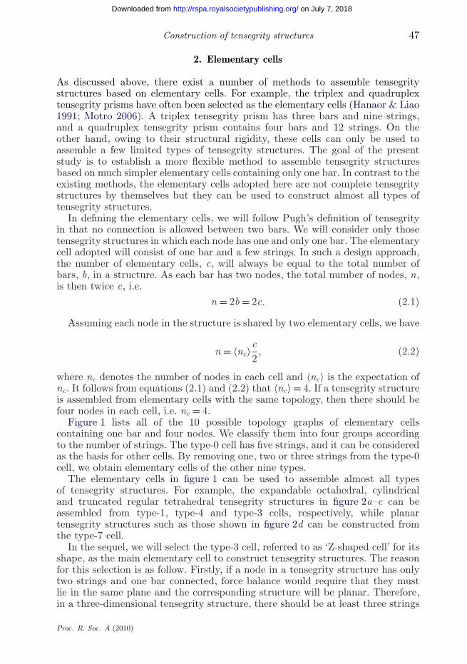
Figure 1 lists all of the 10 possible topology graphs of elementary cellscontaining one bar and four nodes. We classify them into four groups accordingto the number of strings. The type-0 cell has five strings, and it can be consideredas the basis for other cells. By removing one, two or three strings from the type-0cell, we obtain elementary cells of the other nine types.
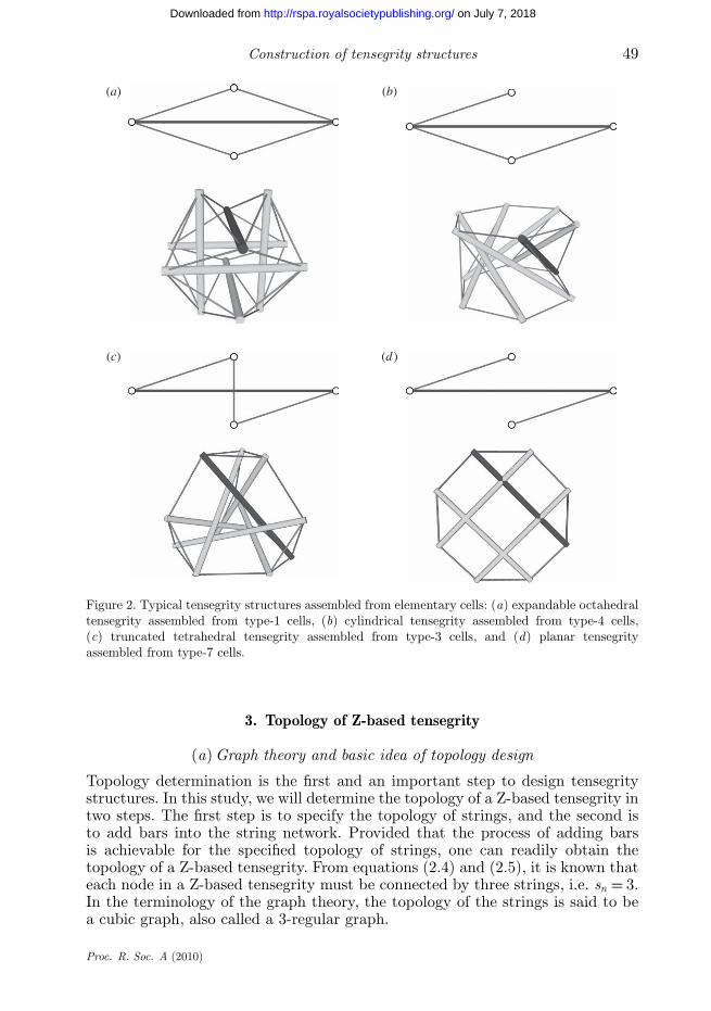
The elementary cells in figure 1 can be used to assemble almost all typesof tensegrity structures. For example, the expandable octahedral, cylindricaland truncated regular tetrahedral tensegrity structures in figure 2a–c can beassembled from type-1, type-4 and type-3 cells, respectively, while planartensegrity structures such as those shown in figure 2d can be constructed fromthe type-7 cell.
In the sequel, we will select the type-3 cell, referred to as ‘Z-shaped cell’ for itsshape, as the main elementary cell to construct tensegrity structures. The reasonfor this selection is as follow. Firstly, if a node in a tensegrity structure has onlytwo strings and one bar connected, force balance would require that they mustlie in the same plane and the corresponding structure will be planar. Therefore,in a three-dimensional tensegrity structure, there should be at least three strings
Proc. R. Soc. A (2010)
on July 7, 2018http://rspa.royalsocietypublishing.org/Downloaded from
48 Y. Li et al.
cells with fivestrings
cells with fourstrings
0
1
2
3
4
5
69
8
7
cells with threestrings
cells with twostrings
Figure 1. The topology graphs of all elementary tensegrity cells containing one bar and four nodes.The solid and grey lines stand for the bars and strings, respectively, and the empty circles denotethe nodes.
connected to a node (Motro 2006), i.e.
sn ≥ 3, (2.3)
where sn denotes the number of strings connected to each node. As each stringin the constructed structure has two nodes, it follows from equations (2.1) and(2.3) that the total number of strings must satisfy
s = nsn
2≥ 3
2n = 3c. (2.4)
If no string is shared by two cells, the number of strings, sc, in each cell of aspatial tensegrity structure should satisfy
sc = sc
≥ 3. (2.5)
The cells of types 7–9 in figure 1 contain only two strings each and cannot be usedto construct a three-dimensional tensegrity structure. Secondly, adding strings toa stable tensegrity structure will not make it unstable, while removing stringsis likely to lead to instability. Therefore, we focus on tensegrity structures inwhich the ratio between the numbers of strings and bars is as small as possible.Therefore, the cells of types 0–2 in figure 1, which contain four or five strings, willnot be considered further in this study. Thirdly, among the cells of types 3–6, eachof which contains three strings, the type-3 or Z-shaped cell can be made a pre-stressed and self-equilibrated one-dimensional structure, while the other threetypes cannot. This means that it should be easier to design a structure underpre-stress stability (Connelly & Whiteley 1996) based on the Z-shaped cell thanon the other three types. Therefore, we will focus on the tensegrity structuresassembled from the Z-shaped cell. The obtained assemblies will be referred to asthe Z-based tensegrity.
Proc. R. Soc. A (2010)
on July 7, 2018http://rspa.royalsocietypublishing.org/Downloaded from
Construction of tensegrity structures 49
(a) (b)
(c) (d)
Figure 2. Typical tensegrity structures assembled from elementary cells: (a) expandable octahedraltensegrity assembled from type-1 cells, (b) cylindrical tensegrity assembled from type-4 cells,(c) truncated tetrahedral tensegrity assembled from type-3 cells, and (d) planar tensegrityassembled from type-7 cells.
3. Topology of Z-based tensegrity
(a) Graph theory and basic idea of topology design
Topology determination is the first and an important step to design tensegritystructures. In this study, we will determine the topology of a Z-based tensegrity intwo steps. The first step is to specify the topology of strings, and the second isto add bars into the string network. Provided that the process of adding barsis achievable for the specified topology of strings, one can readily obtain thetopology of a Z-based tensegrity. From equations (2.4) and (2.5), it is known thateach node in a Z-based tensegrity must be connected by three strings, i.e. sn = 3.In the terminology of the graph theory, the topology of the strings is said to bea cubic graph, also called a 3-regular graph.
Proc. R. Soc. A (2010)
on July 7, 2018http://rspa.royalsocietypublishing.org/Downloaded from
50 Y. Li et al.
It should be noted that there are a large number of cubic graphs. The followingquestions then arise: can all the cubic graphs be used to construct Z-basedtensegrity; and if not, what are the conditions for a cubic graph to be selected?
As the three strings in a Z-shaped cell are linked end to end, their topologyconstitutes a path including three edges according to the graph theory. The twoend vertices of the string path also correspond to the two nodes of the bar in thesame cell. Therefore, once a 3-path decomposition of the cubic graph is admitted,one can easily add the bars into the topology. Here, we quote a pertinent theoremproved by Heinrich et al. (1999).
Theorem. Let G be a simple connected 3m-regular graph, which, when m is odd,has no cut edge. Then G admits a balanced 3-path decomposition.
In the case of m = 1, this theorem is reduced to the following proposition:‘Every simple bridgeless cubic graph G admits a balanced 3-path decomposition’.
Here, balanced path decomposition means that ‘each vertex of G is an endvertex of s paths of the decomposition for some fixed s’ (Heinrich et al. 1999).It is evident that s can only be equal to 1 for the 3-path decomposition of acubic graph. From the viewpoint of a tensegrity structure, this ensures that thereis no connection between bars. The balanced decomposition also excludes thesituation where the two end vertices of a path coincide. This means that thetwo nodes of an added bar must be different or, in other words, no bar of zerolength can exist in a tensegrity structure. Such a structure perfectly matchesthe tensegrity definition. Therefore, the above proposition provides a sufficientcondition for the cubic graphs, which can be used as the string topology of aZ-based tensegrity. Furthermore, we can prove that the restrictions of the cubicgraph in the proposition are also necessary for designing a practical tensegritystructure. Firstly, the topology of strings in the tensegrity structures under studyhas neither multiple edges nor self-loops or, in the terminology of the graphtheory, the corresponding cubic graph is always simple. Secondly, the topologyof strings in the tensegrity structures of interest must also be bridgeless. In thegraph theory, a bridge is defined as an edge (or a string in the tensegrity structureunder study) whose removal will disconnect the graph into two separate parts.Thus, a structure with a ‘bridge’ is unstable and impractical.
From the above proposition and discussions, we have the following corollaryfor Z-based tensegrity structures:
Corollary. A Z-based tensegrity structure can be constructed by adding barsto a string net if and only if the topology of strings is a simple and bridgelesscubic graph.
Based on this corollary, one can construct the topology of the structure froma cubic graph. Once the topology is determined, the next step is to set properoriginal lengths and stiffness of the bars and strings before using a form-findingprocedure. As the two parameters are not independent for the form-finding ofa tensegrity, for the sake of simplicity, we set the stiffness of all elements asunity. Generally, to keep a tensegrity structure in a state of pre-stress stability,its strings are all in tension and bars in compression (Connelly & Whiteley 1996).An obvious way to achieve such a pre-stressed state is to set the bar length ineach cell to be longer than the total length of its three strings.
Proc. R. Soc. A (2010)
on July 7, 2018http://rspa.royalsocietypublishing.org/Downloaded from
Construction of tensegrity structures 51
(a) (b) (c)
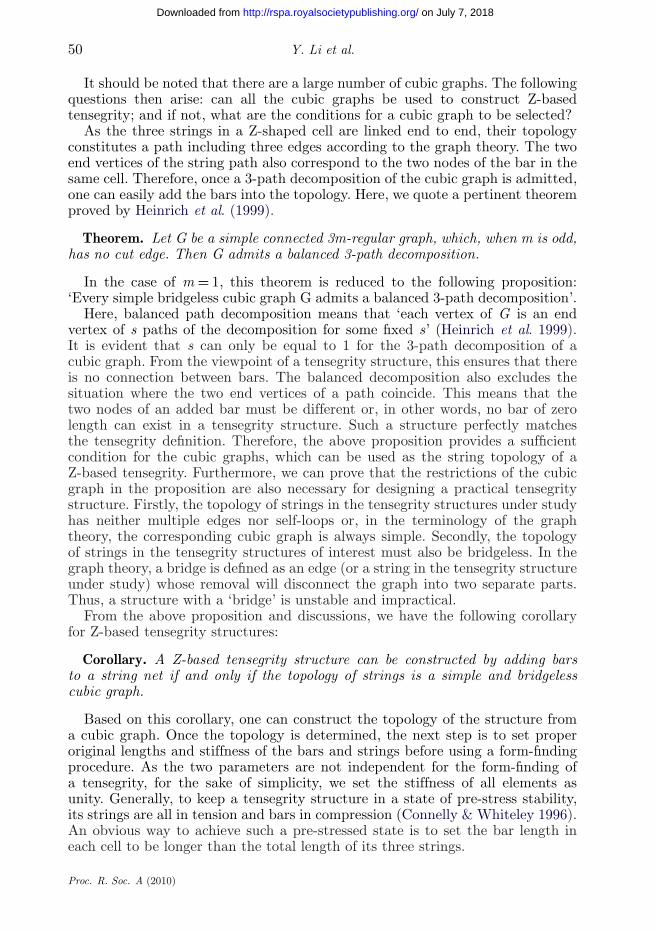
Figure 3. Construction of Z-based tensegrity based on a pentagonal prism. (a) The topology of apentagonal prism. (b) The topology of the pentaplex tensegrity prism, where the solid black linesdenote the bars and the grey lines denote the strings. (c) The form-finding result of the pentaplextensegrity prism.
As the final step of design, the equilibrium configuration of the tensegritystructure is found by using the Monte Carlo form-finding (MCFF) methodrecently developed by the authors (Li et al. submitted). The MCFF methodis based on an accept-or-reject scheme. In each iteration step, one generatesa trial configuration through random sampling and then compares it with theconfiguration of the previous step. If the trial configuration has lower energy thanthe previous one, it will be accepted; otherwise it will be rejected. The essenceof the MCFF procedure is to search for the equilibrium state of a tensegritystructure that minimizes the system energy. The iteration will be terminatedafter the equilibrium state has been reached.
(b) Examples
To illustrate some applications of the proposed topology design method, anumber of simple examples will be given in the following. It can be shownthat all polyhedra with three edges connected at each node satisfy the topologyrequirements in the corollary. This has inspired us to construct Z-based tensegritystructures following the topology of a polyhedron.
For string nets with a regular cubic graph topology, we can manually addthe needed bars for tensegrity. For instance, take the pentagonal prism as thetopology of a string net, as shown in figure 3a. The topology after adding barsis shown in figure 3b, and the final form-finding result of the tensegrity usingthe MCFF method is shown in figure 3c. The obtained structure is named asD1,2
5 prismatic tensegrity in Zhang et al. (2009), which is also a special caseof traditional cylindrical tensegrity consisting of five bars (Tibert & Pellegrino2003). As all the prisms are cubic graphs, we can construct many other cylindricaltensegrity structures in a similar way.
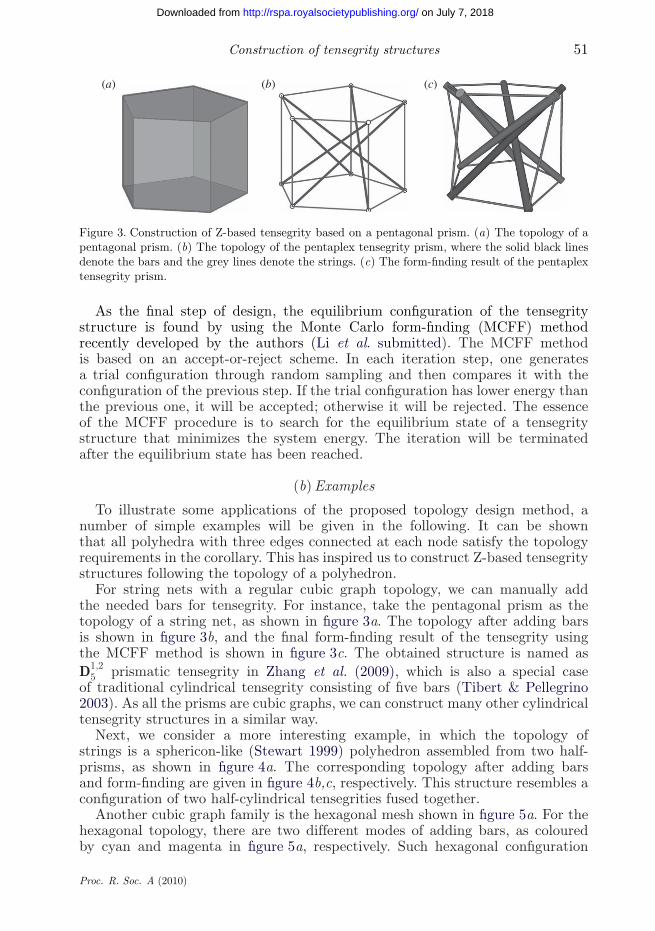
Next, we consider a more interesting example, in which the topology ofstrings is a sphericon-like (Stewart 1999) polyhedron assembled from two half-prisms, as shown in figure 4a. The corresponding topology after adding barsand form-finding are given in figure 4b,c, respectively. This structure resembles aconfiguration of two half-cylindrical tensegrities fused together.
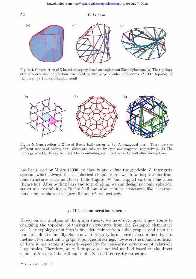
Another cubic graph family is the hexagonal mesh shown in figure 5a. For thehexagonal topology, there are two different modes of adding bars, as colouredby cyan and magenta in figure 5a, respectively. Such hexagonal configuration
Proc. R. Soc. A (2010)
on July 7, 2018http://rspa.royalsocietypublishing.org/Downloaded from
52 Y. Li et al.
(a) (b) (c)
Figure 4. Construction of Z-based tensegrity based on a sphericon-like polyhedron. (a) The topologyof a sphericon-like polyhedron assembled by two perpendicular half-prisms. (b) The topology ofthe bars. (c) The form-finding result.
(a) (b) (c)
Figure 5. Construction of Z-based Bucky ball tensegrity. (a) A hexagonal mesh. There are twodifferent modes of adding bars, which are coloured by cyan and magenta, respectively. (b) Thetopology of a C60 Bucky ball. (c) The form-finding result of the Bucky ball after adding bars.
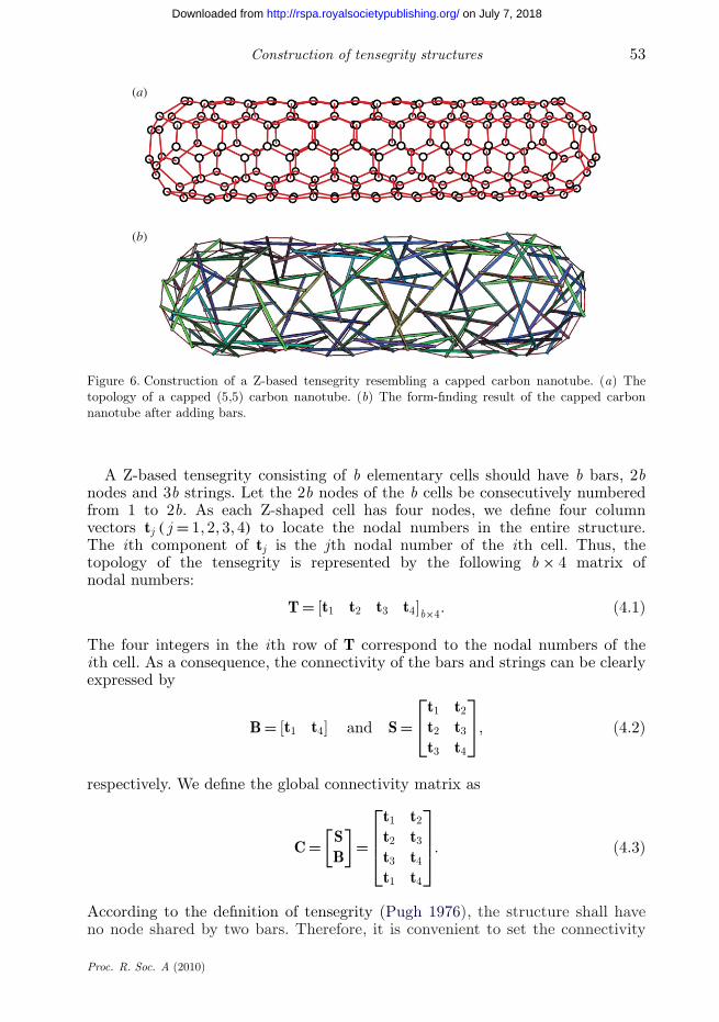
has been used by Motro (2006) to classify and define the geodesic ‘Z’ tensegritysystem, which always has a spherical shape. Here, we draw inspirations fromnanostructures such as Bucky balls (figure 5b) and capped carbon nanotubes(figure 6a). After adding bars and form-finding, we can design not only sphericalstructures resembling a Bucky ball but also tubular structures like a carbonnanotube, as shown in figures 5c and 6b, respectively.
4. Direct enumeration scheme
Based on our analysis of the graph theory, we have developed a new route todesigning the topology of tensegrity structures from the Z-shaped elementarycell. The topology of strings is first determined from cubic graphs, and then thebars are added manually. Some novel tensegrity forms have been obtained by thismethod. For most cubic graph topologies of strings, however, the manual additionof bars is not straightforward, especially for tensegrity structures of relativelylarge scales. Therefore, we will propose a canonical method based on the directenumeration of all the cell nodes of a Z-based tensegrity structure.
Proc. R. Soc. A (2010)
on July 7, 2018http://rspa.royalsocietypublishing.org/Downloaded from
Construction of tensegrity structures 53
(a)
(b)
Figure 6. Construction of a Z-based tensegrity resembling a capped carbon nanotube. (a) Thetopology of a capped (5,5) carbon nanotube. (b) The form-finding result of the capped carbonnanotube after adding bars.
A Z-based tensegrity consisting of b elementary cells should have b bars, 2bnodes and 3b strings. Let the 2b nodes of the b cells be consecutively numberedfrom 1 to 2b. As each Z-shaped cell has four nodes, we define four columnvectors tj ( j = 1, 2, 3, 4) to locate the nodal numbers in the entire structure.The ith component of tj is the jth nodal number of the ith cell. Thus, thetopology of the tensegrity is represented by the following b × 4 matrix ofnodal numbers:
T = [t1 t2 t3 t4]b×4. (4.1)
The four integers in the ith row of T correspond to the nodal numbers of theith cell. As a consequence, the connectivity of the bars and strings can be clearlyexpressed by
B = [t1 t4] and S =⎡⎣t1 t2
t2 t3
t3 t4
⎤⎦, (4.2)
respectively. We define the global connectivity matrix as
C =[SB
]=
⎡⎢⎢⎣
t1 t2
t2 t3
t3 t4
t1 t4
⎤⎥⎥⎦. (4.3)
According to the definition of tensegrity (Pugh 1976), the structure shall haveno node shared by two bars. Therefore, it is convenient to set the connectivity
Proc. R. Soc. A (2010)
on July 7, 2018http://rspa.royalsocietypublishing.org/Downloaded from
54 Y. Li et al.
1 2
3 1
44 2
3
(a) (b)
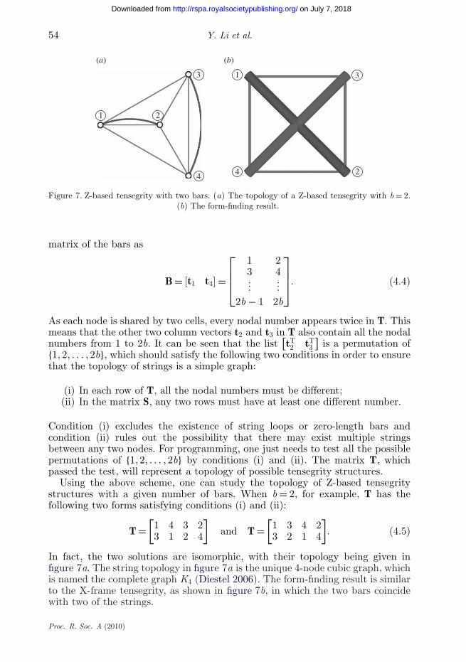
Figure 7. Z-based tensegrity with two bars. (a) The topology of a Z-based tensegrity with b = 2.(b) The form-finding result.
matrix of the bars as
B = [t1 t4] =
⎡⎢⎢⎣
1 23 4...
...2b − 1 2b
⎤⎥⎥⎦. (4.4)
As each node is shared by two cells, every nodal number appears twice in T. Thismeans that the other two column vectors t2 and t3 in T also contain all the nodalnumbers from 1 to 2b. It can be seen that the list
[tT2 tT
3
]is a permutation of
{1, 2, . . . , 2b}, which should satisfy the following two conditions in order to ensurethat the topology of strings is a simple graph:
(i) In each row of T, all the nodal numbers must be different;(ii) In the matrix S, any two rows must have at least one different number.
Condition (i) excludes the existence of string loops or zero-length bars andcondition (ii) rules out the possibility that there may exist multiple stringsbetween any two nodes. For programming, one just needs to test all the possiblepermutations of {1, 2, . . . , 2b} by conditions (i) and (ii). The matrix T, whichpassed the test, will represent a topology of possible tensegrity structures.
Using the above scheme, one can study the topology of Z-based tensegritystructures with a given number of bars. When b = 2, for example, T has thefollowing two forms satisfying conditions (i) and (ii):
T =[1 4 3 23 1 2 4
]and T =
[1 3 4 23 2 1 4
]. (4.5)
In fact, the two solutions are isomorphic, with their topology being given infigure 7a. The string topology in figure 7a is the unique 4-node cubic graph, whichis named the complete graph K4 (Diestel 2006). The form-finding result is similarto the X-frame tensegrity, as shown in figure 7b, in which the two bars coincidewith two of the strings.
Proc. R. Soc. A (2010)
on July 7, 2018http://rspa.royalsocietypublishing.org/Downloaded from
Construction of tensegrity structures 55
1 13
5
4 2
6 7
5
3
15
8
4
6
3
2
7
7
6
4
28
5
3 1
2
8
6
4(a) (b)
(c) (d )
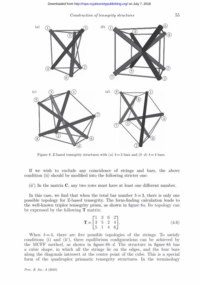
Figure 8. Z-based tensegrity structures with (a) b = 3 bars and (b–d) b = 4 bars.
If we wish to exclude any coincidence of strings and bars, the abovecondition (ii) should be modified into the following stricter one:
(ii′) In the matrix C, any two rows must have at least one different number.
In this case, we find that when the total bar number b = 3, there is only onepossible topology for Z-based tensegrity. The form-finding calculation leads tothe well-known triplex tensegrity prism, as shown in figure 8a. Its topology canbe expressed by the following T matrix:
T =[1 3 6 23 5 2 45 1 4 6
]. (4.6)
When b = 4, there are five possible topologies of the strings. To satisfyconditions (i) and (ii′), three equilibrium configurations can be achieved bythe MCFF method, as shown in figure 8b–d. The structure in figure 8b hasa cubic shape, in which all the strings lie on the edges, and the four barsalong the diagonals intersect at the centre point of the cube. This is a specialform of the quadruplex prismatic tensegrity structures. In the terminology
Proc. R. Soc. A (2010)
on July 7, 2018http://rspa.royalsocietypublishing.org/Downloaded from
56 Y. Li et al.
of Zhang et al. (2009), the topology of this structure corresponds to D1,24 .
Evidently, it is different from the conventional quadruplex (or half-cuboctahedron) tensegrity D1,1
4 , which does not belong to the family of Z-basedstructures. The two structures in figure 8c and d have the same string topologybut two different ways of adding bars. The T matrices of the structures infigure 8b–d are
T(b) =⎡⎢⎣
1 6 3 23 7 5 45 2 8 67 1 4 8
⎤⎥⎦, T(c) =
⎡⎢⎣
1 5 3 23 1 7 45 8 2 67 6 4 8
⎤⎥⎦ and T(d) =
⎡⎢⎣
1 4 6 23 7 2 45 8 3 67 5 1 8
⎤⎥⎦,
(4.7)
respectively.With increasing b, the number of possible topologies grows very rapidly.
For a specified b, one can in principle enumerate all possible topologies ofZ-based tensegrity structures, by replacing the list
[tT2 tT
3
]with all the possible
permutations of {1, 2, . . . , 2b}, followed by elimination of configurations that areisomorphic or violate condition (i) or (ii′).
5. Polyhedral truncation scheme
(a) Methodology
The direct enumeration scheme in §4 allows us to find the topologies of all theZ-based tensegrity structures for a specified number of cells, and it is also usefulto study the topology of relatively small-scale tensegrity structures. To designa tensegrity structure of a larger scale, however, the direct enumeration schemewould become time consuming. For a large value of b, the number of possibletopologies can be huge and most of them lead to impractical configurations thatare either irregular or have intersecting bars. Therefore, for designing Z-basedtensegrity structures of a larger scale, further simplification of the assemblyprocedure is necessary. To this end, we propose a much simpler scheme, referredto as the polyhedral truncation scheme, based on the graph analysis in §3. In thisscheme, we will use a polyhedron to determine the approximate configuration ofthe tensegrity structure in design and obtain the topology of strings by its vertextruncation. The polyhedron is truncated by cutting all its original vertices andcreating a new polygonal facet around each vertex. No matter how many edgesare connected at a vertex in the original polyhedron, the truncation will makeeach new vertex having just three edges connected. That is, the new polyhedron isguaranteed to be an appropriate cubic graph for the design of Z-based tensegritystructures. For instance, figure 9a shows a pyramid, which is originally not acubic graph because the vertex G has four edges. However, the polyhedron, aftertruncation, has evidently become a cubic graph with three edges at each vertex.
The truncation method is not only convenient in constructing cubic graphsto be used as the topology of strings but also in the addition of bars. We stilltake the pyramid in figure 9a as an example. The red lines denote the new edges
Proc. R. Soc. A (2010)
on July 7, 2018http://rspa.royalsocietypublishing.org/Downloaded from
Construction of tensegrity structures 57
E
K
JA
I
C
HD
F
B
G(a) (b)
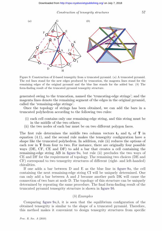
Figure 9. Construction of Z-based tensegrity from a truncated pyramid. (a) A truncated pyramid.The red lines stand for the new edges produced by truncation, the magenta lines stand for theremaining edges of the original pyramid and the blue line stands for the added bar. (b) Theform-finding result of the truncated pyramid tensegrity structure.
generated owing to the truncation, named the ‘truncating-edge strings’; and themagenta lines denote the remaining segment of the edges in the original pyramid,called the ‘remaining-edge strings’.
Once the topology of strings has been obtained, we can add the bars in atruncated polyhedron according to the following two rules:
(i) each cell contains only one remaining-edge string, and this string must bein the middle of the two others;
(ii) the two nodes of each bar must be on two different polygon faces.
The first rule determines the middle two column vectors t2 and t3 of T inequation (4.1), and the second rule makes the tensegrity configuration have ashape like the truncated polyhedron. In addition, rule (ii) reduces the options ofeach row in T from four to two. For instance, there are originally four possibleways (DE, CF, CE and DF) to add a bar that creates a cell containing theremaining-edge string AB in figure 9a, but rule (ii) precludes the two ways ofCE and DF for the requirement of topology. The remaining two choices (DE andCF) correspond to two tensegrity structures of different (right- and left-handed)chiralities.
If one adds a bar between D and E as the blue line in figure 9a, the cellcontaining the next remaining-edge string CI will be uniquely determined. Onecan only add a bar between A and J because another path DK will cause theconnection of two bars at node D. The topology of this structure can be uniquelydetermined by repeating the same procedure. The final form-finding result of thetruncated pyramid tensegrity structure is shown in figure 9b.
(b) Examples
Comparing figure 9a,b, it is seen that the equilibrium configuration of theobtained tensegrity is similar to the shape of a truncated pyramid. Therefore,this method makes it convenient to design tensegrity structures from specific
Proc. R. Soc. A (2010)
on July 7, 2018http://rspa.royalsocietypublishing.org/Downloaded from
58 Y. Li et al.
(a) (b)
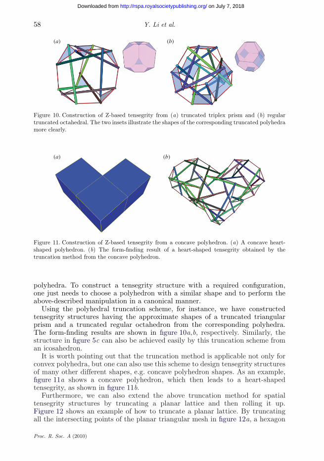
Figure 10. Construction of Z-based tensegrity from (a) truncated triplex prism and (b) regulartruncated octahedral. The two insets illustrate the shapes of the corresponding truncated polyhedramore clearly.
(a) (b)
Figure 11. Construction of Z-based tensegrity from a concave polyhedron. (a) A concave heart-shaped polyhedron. (b) The form-finding result of a heart-shaped tensegrity obtained by thetruncation method from the concave polyhedron.
polyhedra. To construct a tensegrity structure with a required configuration,one just needs to choose a polyhedron with a similar shape and to perform theabove-described manipulation in a canonical manner.
Using the polyhedral truncation scheme, for instance, we have constructedtensegrity structures having the approximate shapes of a truncated triangularprism and a truncated regular octahedron from the corresponding polyhedra.The form-finding results are shown in figure 10a,b, respectively. Similarly, thestructure in figure 5c can also be achieved easily by this truncation scheme froman icosahedron.
It is worth pointing out that the truncation method is applicable not only forconvex polyhedra, but one can also use this scheme to design tensegrity structuresof many other different shapes, e.g. concave polyhedron shapes. As an example,figure 11a shows a concave polyhedron, which then leads to a heart-shapedtensegrity, as shown in figure 11b.
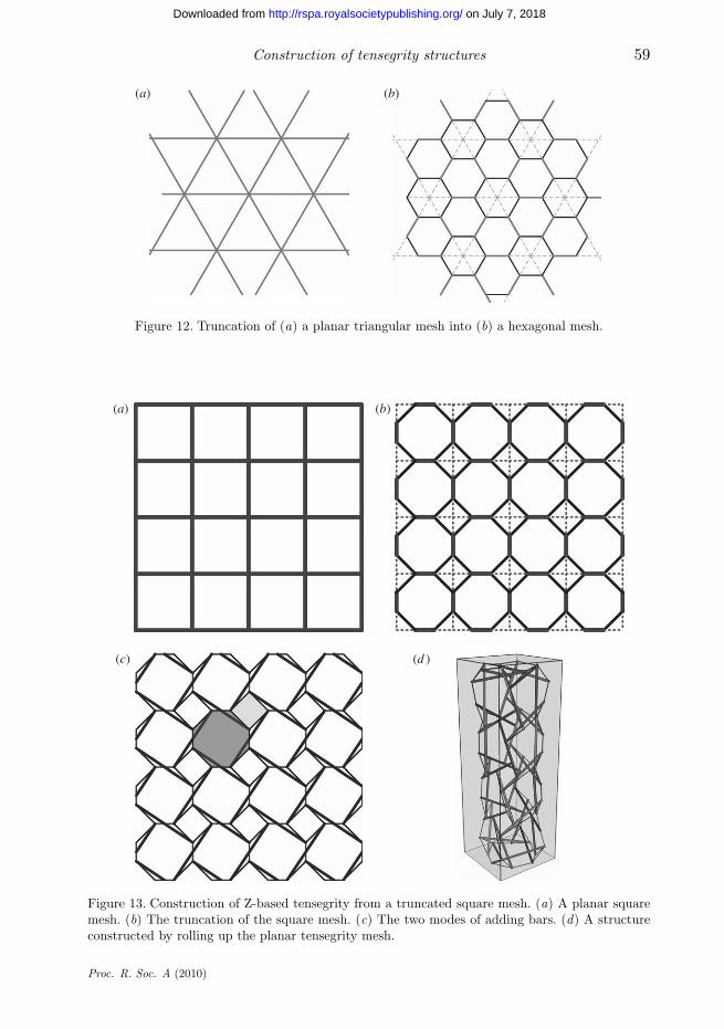
Furthermore, we can also extend the above truncation method for spatialtensegrity structures by truncating a planar lattice and then rolling it up.Figure 12 shows an example of how to truncate a planar lattice. By truncatingall the intersecting points of the planar triangular mesh in figure 12a, a hexagon
Proc. R. Soc. A (2010)
on July 7, 2018http://rspa.royalsocietypublishing.org/Downloaded from
Construction of tensegrity structures 59
(a) (b)
Figure 12. Truncation of (a) a planar triangular mesh into (b) a hexagonal mesh.
(a) (b)
(c) (d )
Figure 13. Construction of Z-based tensegrity from a truncated square mesh. (a) A planar squaremesh. (b) The truncation of the square mesh. (c) The two modes of adding bars. (d) A structureconstructed by rolling up the planar tensegrity mesh.
Proc. R. Soc. A (2010)
on July 7, 2018http://rspa.royalsocietypublishing.org/Downloaded from
60 Y. Li et al.
mesh is obtained, as shown in figure 12b. Following the two rules in §5a, the twomodes of adding bars in figure 5a can be implemented. Such graphene-like planarstructure can be rolled up into tensegrity structures having the shape of a cappedcarbon nanotube (Reich et al. 2005), as shown in figure 6b.
As another example of planner lattices, figure 13a shows a square mesh.Similarly, the truncation of this lattice and the addition of bars are shown infigure 13b,c, respectively, which leads to some new types of tensegrity, e.g. thestructure of a quadrangular prism shape in figure 13d.
The above examples demonstrate that the truncation method provides anefficient and programmable approach to designing tensegrity structures.
6. Conclusions
In the present paper, we have demonstrated a promising approach to constructingthree-dimensional tensegrity structures from elementary cells. Among all the basiccells with only one bar, we have chosen to focus in this paper upon the Z-shapedcell to assemble the so-called Z-based tensegrity structures, which are in strictcompliance with the definition of tensegrity. Our analysis based on the graphtheory of topology shows that Z-based tensegrity structures can be constructed byadding a pre-determined number of bars into string nets with a simple bridgelesscubic graph topology.
Starting from the above basic idea, we have developed two different schemesto assemble Z-based tensegrity structures. One is the direct enumeration scheme,which systematically searches for all possible topologies for Z-based tensegrity fora given number of cells and then filters out the unwanted structures among thepossible solutions. The other, named the polyhedral truncation scheme, providesa more efficient and fast way for the practical design of tensegrity structures. Toconstruct a tensegrity structure with a required configuration, one just selectsa polyhedron with a similar shape, truncates all its vertices and then adds thebars in a canonical manner. Both schemes are easily programmable, and havegenerated a number of novel tensegrity structures. Finally, it is worth mentioningthat, among all types of spatial tensegrity structures, the Z-based structures havethe smallest ratio between the numbers of strings and bars, and can be utilizedto further construct many other types of stable structures by adding additionalstrings.
The support from the National Natural Science Foundation of China (grant nos. 10525210 and10732050) and 973 Program (2010CB631005) is acknowledged.
References
Connelly, R. & Back, A. 1998 Mathematics and tensegrity. Am. Sci. 86, 142–151. (doi:10.1511/1998.2.142)
Connelly, R. & Whiteley, W. 1996 Second-order rigidity and prestress stability for tensegrityframeworks. SIAM J. Discrete Math. 9, 453–491. (doi:10.1137/S0895480192229236)
Diestel, R. 2006 Graph theory. New York, NY: Springer-Verlag.Emmerich, D. G. 1965 Construction de réseaux autotendants. French Patent 1377290.Fu, F. 2005 Structural behavior and design methods of tensegrity domes. J. Constr. Steel Res. 61,
23–35. (doi:10.1016/j.jcsr.2004.06.004)
Proc. R. Soc. A (2010)
on July 7, 2018http://rspa.royalsocietypublishing.org/Downloaded from
Construction of tensegrity structures 61
Fuller, R. B. 1962 Tensile-integrity structures. United States Patent 3063521.Hanaor, A. & Liao, M. K. 1991 Double-layer tensegrity grids—static load response 1: analytical
Study. J. Struct. Eng. 117, 1660–1674. (doi:10.1061/(ASCE)0733-9445(1991)117:6(1660))Heinrich, K., Liu, J. P. & Yu, M. L. 1999 P4-decompositions of regular graphs. J. Graph Theory
31, 135–143. (doi:10.1002/(SICI)1097-0118(199906)31:2<135::AID-JGT6>3.0.CO;2-I)Ingber, D. E. 1993 Cellular tensegrity: defining new rules of biological design that govern the
cytoskeleton. J. Cell Sci. 104, 613–627.Ingber, D. E. 1997 Tensegrity: the architectural basis of cellular mechanotransduction. Annu. Rev.
Physiol. 59, 575–599. (doi:10.1146/annurev.physiol.59.1.575)Juan, S. H. & Tur, J. M. M. 2008 Tensegrity frameworks: static analysis review. Mech. Mach.
Theory 43, 859–881. (doi:10.1016/j.mechmachtheory.2007.06.010)Li, Y., Feng, X. Q., Cao, Y. P. & Gao, H. J. Submitted. A Monte Carlo form-finding method for
large scale regular and irregular tensegrity structures. Int. J. Solids Struct.Luo, H. X. & Bewley, T. R. 2005 Accurate simulation of near-wall turbulence over a compliant
tensegrity fabric. Proc. SPIE 5757, 184–197. (doi:10.1117/12.600582)Motro, R. 2006 Tensegrity: structural systems for the future. London, UK: Butterworth-Heinemann.Pugh, A. 1976 An introduction to tensegrity. Berkeley, CA: University of California Press.Reich, S., Li, L. & Robertson, J. 2005 Structure and formation energy of carbon nanotube caps.
Phys. Rev. B 72, 165423. (doi:10.1103/Physrevb.72.165423)Skelton, R. E., Williamson, D. & Han, J. 2002 Equilibrium conditions of a class I tensegrity
structure. Adv. Astronaut. Sci. 112, 927–949.Snelson, K. D. 1965 Continuous tension, discontinuous compression structures. United States
Patent 3169611.Stewart, I. 1999 Cone with a twist. Sci. Am. 281, 116–117.Tibert, A. G. & Pellegrino, S. 2003 Review of form-finding methods for tensegrity structures. Int.
J. Space Struct. 18, 209–223. (doi:10.1260/026635103322987940)Wang, B. B. 1998a Cable-strut systems: Part I—tensegrity. J. Constr. Steel Res. 45, 281–289.
(doi:10.1016/S0143-974X(97)00075-8)Wang, B. B. 1998b Cable-strut systems: Part II—cable-strut. J. Constr. Steel Res. 45, 291–299.
(doi:10.1016/S0143-974X(97)00076-X)Zhang, J. Y., Guest, S. D. & Ohsaki, M. 2009 Symmetric prismatic tensegrity structures: Part I.
Configuration and stability. Int. J. Solids Struct. 46, 1–14. (doi:10.1016/j.ijsolstr.2008.08.032)
Proc. R. Soc. A (2010)
on July 7, 2018http://rspa.royalsocietypublishing.org/Downloaded from


![Constructing Tensegrity Frameworks[1ex] and Related … · 2019. 2. 28. · ISBN (e-book): 978-94-034-0693-0. Constructing Tensegrity Frameworks and Related Applications in Multi-Agent](https://img.dokumen.tips/doc/110x75/5fc90f3014ef0f43a247f7fb/constructing-tensegrity-frameworks1ex-and-related-2019-2-28-isbn-e-book.jpg)