Embed Size (px)
Citation preview

3
!In order to respond better to customer requirements or expectations, LPG Systems is continuously researching ways of improving the design and quality of its products. This will explain the few minor differences between your equipment and the item described in this guide. If you own a Cellu M6 Keymodule i, some chapters of this user guide do not apply as specified in this document.
Congratulations on the purchase of your Cellu M6 Keymodule [2]i. This model represents the fruits of numerous years of experience in the design and production of cutaneous tissue treatment systems. You will experience fully the technical perfection and reliability of LPG Systems, which is the leader in this sector. This operator’s manual contains the operating description, basic maintenance instructions to be performed periodically and the safety instructions. You are reminded that your device is designed for the treatment of connective tissue and that it must only be used by a professional trained by LPG Systems or an authorized distributor if you live outside France. If you have any doubts whatsoever concerning the operation or maintenance of your equipment, please do not hesitate to contact LPG the Customer Service Department of your distributor.
Please read the complete manual carefullybefore using your equipment.
© Copyright LPG Systems 2007. LPG, Cellu M6, Keymodule and Endermologie Photo Systemare registered trademarks of LPG.
Reproduction, even in part, is strictly prohibited.
GU 350
Edition A dated 03/07
O P E R A T O R ’ S M A N U A L
Registered trademark
1

! The manufacturer reserves the right to amend the product technical specifications without prior notice. Any reproduc-tion – even in part – is prohibited. All the illustrations in this operator’s manual are non-binding.
Table of contentsPackage contents
!Unpacking instructions to be retained.The package contents are identical, except for the Cellu M6 Keymodule i device, the face heads are not available on this version.
4 5
• One Cellu M6 Keymodule [2]i unit
• One main T70 head
• Three Keymodule
• One supply cable
• A set of auxiliary heads
• A set of micro-nozzles/micro-heads
• A set of lift heads
• One operator’s manual
• One maintenance kit
• Marketing environment
1 description of the unit ............................................ p. 6
2 description of the controls ...................................... p. 8
3 precautions for use .................................................. p. 9
4 maintenance ............................................................p. 11
5 operating faults .....................................................p. 21
6 technical specifications ..........................................p. 22
7 treatment heads .....................................................p. 24
8 warranty ................................................................p. 39
9 accessories .............................................................p. 42

!The unit can only operate if it is connected to the mains by its supply cable and provided the ON switch has been actuated and the green voltage light is on When the unit is switched on, the pump starts to run automatically forabout ten seconds for priming.
1d
es
cr
ipt
ion
o
f t
he
un
it
auxiliaryhead hose
access door to filters and maintenance kit
articulating arm
for main head
air inlet forventilation
protection strip
gripping areafor raising the unit
main treatment head
main head hose
drawer for storingthe auxiliary heads
keymodule
pivoting wheels
gripping area formoving the unit
connectionof auxiliary
treatment head
articulatingarm for
auxiliary head
adjustable mobilearm rods
air outlets fromventilation circuit
electrical cable support
on/off switchmain’s filterand fuse holder
access doorto technical
elementselectrical cable
data plate
BEFORE USE MAKE SURE THAT THE SUPPLY CABLE IS COMPLETELY UNWOUND
Access to the filters
auxiliary head filter
main head filter
maintenance kit
controlpanel
Cellu M6® Keymodule [2] i 1d
es
cr
ipt
ion
of
th
e u
nit
6 7
Drawer for storing theseries 600 auxiliary heads
Cellu M6 Keymodule [2]i Cellu M6 Keymodule i*
! * The auxilary heads are replaced by the 600 series auxilary heads.
monitor screen

• Check that the supply voltage of the unit indicated on the data plate complies with the mains voltage.
• The unit must be connected to a grounded outlet in accordance with current electri-cal standards.
• Never use the unit on a dusty, uneven floor, or in a moist atmosphere.
• Check that the inlet to the ventilation circuit is always unobstructed.
• Fully unwind the supply electrical from its support to ensure good ventilation of the unit.
• Switch the unit off if it is not going to be used for a long period. In this case, operate the machine for a 1/2 an hour approximately every 8 weeks.
• Do not allow solid debris or liquid to be sucked into the unit, as these could cause damage.
• Never use the auxiliary adapter as a treat-ment head or allow it to come into direct contact with the skin.
• Do not use the main head to carry out treatment on the scalp.
• Only use the treatment heads supplied with your unit or recommended by LPG.
• Only use LPG Systems treatment garments.
• Never use the unit for purposes other than those recommended by LPG Systems.
• LPG Systems will not be liable for any inappropriate use of the equipment.
• With respect to treated tissue, some parameters may cause pain or tissue lesions. The operator must be particularly attentive to the sensations felt by the person undergoing treatment where:
- the intensity is greater than 4 in continuous or sequential mode (for frequencies less than 4 Hz),
- the system has changed to reverse mode (rollers rotating in opposite direction).
• The operator must ensure that the parameters (intensity, sequentiality, differential...) are always adapted to the cutaneous tissue being treated.
• You are advised to rest the device for 10 minutes between each 35-minute treatment session when using it at a room temperature higher than 25°C (77°F).
! Where the unit has not been used for a long time, it is possible that marks may form on the ground where the wheels are. This phenomenon is the result of a chemical reaction between the components of some floorings and those of the wheels of the Cellu M6 Keymodule [2] i.
PrecautionsControl panel
Main head
2d
esc
rip
tio
n o
f th
e c
on
tro
ls
3p
re
ca
ut
ion
s
fo
r u
se
8 9
control screen
stop/start key
parameterskeys
return tomenu
escapekey
program selection keys
roller speedadjustment keys
frequencyadjustmentkeys
rollerselection key
initial rollselection key
stop/start keys
control screen

! ALL THE MAINTENANCE OPERATIONS DESCRIBED IN THIS SECTION MUST BE CARRIED OUT WITH THE UNIT SWITCHED OFF AND THE POWER CABLE DISCONNECTED.
Index
identification rating plate p. 12
time meters p. 13
cleaning the unit p. 14
replacing filter cartridges p. 15
replacing fuses p. 16
instructions for disconnecting the treatment heads p. 16
access to the technical items p. 17
replacing the filters of the vacuum generator p. 18
transport/storage p. 19
maintenance kit p. 20
maintenance file p. 20
4m
ain
te
na
nc
e
11
• Do not treat open wounds, the eyes, intra-cavity areas, mucous membranes, the genitals and breasts.
• In the event of pregnancy, do not treat the lumbar-abdominal region. Consult with the doctor with regard to this treat-ment.
• Do not treat a patient with an infectious disease, a growing tumour, phlebitis etc.
• Consult with the doctor where the subject has a case history of tumours or is in remission.
• Do not treat any swollen or inflamed areas without seeking medical advice and without training in the LPG technique in this particular area.
• Make sure that the patient does not have a peacemaker to prevent electronic inter-ferences.
Contra-indications:Because of the risk of interference, it is important that the professional ensures the patient is not equipped with a personal medical device such as a pacemaker. If this is the case, the pro-fessional should obtain details about the device in question to ensure that any interference will not affect the correct use of the equipment.
!This unit contains programs to help the operator obtain the best anticipated results for each case undergoing treat-ment. Under no circumstances may these programs be construed as a guarantee of successful treatment, which varies, depending on the morphology, physiology and eating behaviour of each patient.
Contra-indications
• Do not treat a patient suffering from inexplicable and persistent pain without seeking medical advice and without training in the LPG technique in this particular area.
• Do not treat a patient following invasive medical treatment, without seeking the medical advice of the doctor or surgeon who performed this operation and without training in the LPG technique in this par-ticular area.
For a more detailed list of the indications and contraindications of Endermologie, please refer to the training manuals.
As this list is not exhaustive, always seek out medical advice in the event of doubt.
3p
re
ca
ut
ion
s
fo
r u
se
10
4m
ain
te
na
nc
e
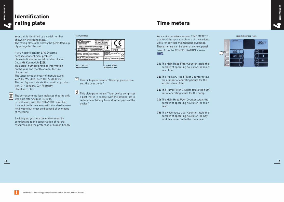
! The identification rating plate is located on the bottom, behind the unit.
Identification rating plate
Your unit is identified by a serial number shown on the rating plate.The rating plate also shows the permitted sup-ply voltage for the unit.
If you need to contact LPG Systems because of a technical problem, please indicate the serial number of your Cellu M6 Keymodule [2] i .This serial number provides information on the year and month of manufacture of your unit. The letter gives the year of manufacture: V= 2005, W= 2006, X= 2007, Y= 2008, etc.The two figures indicate the month of produc-tion: 01= January, 02= February, 03= March, etc.
The corresponding icon indicates that the unit was sold after August 13, 2006. In conformity with the 2002/96/CE directive, it cannot be thrown away with standard house-hold waste but must be disposed of by means of recycling.
By doing so, you help the environment by contributing to the conservation of natural resources and the protection of human health.
Time meters
serial number
supply voltage and frequency
year and month of manufacture
4m
ain
te
na
nc
e
12
Your unit comprises several TIME METERS that total the operating hours of the various units for periodic maintenance purposes. These meters can be seen at control panel level, from the CONFIGURATION screen
.
C1: The Main Head Filter Counter totals the number of operating hours for the main head filter.
C2: The Auxiliary Head Filter Counter totals the number of operating hours for the auxiliary head filter.
C3: The Pump Filter Counter totals the num-ber of operating hours for the pump.
C4: The Main Head User Counter totals the number of operating hours for the main head.
C5: The Keymodule User Counter totals the number of operating hours for the Key-module connected to the main head.
13
from the control panel
This pictogram means “Warning, please con-sult the user guide.”
This pictogram means “Your device comprises a part that is in contact with the patient that is isolated electrically from all other parts of the device.”

4m
ain
te
na
nc
e
Cleaning the unit4
ma
int
en
an
ce
14 15
! Do not use aggressive products, such as acetone, trichloroethylene or alcohol, or abrasive sponges.
Replacing filter cartridges
14 15
We recommend that you clean your unit as often as possible, not only for reasons of hygiene and aesthetics but also because cleaning the unit will help keep it in a good state of repair and extend its useful life.
Using a vacuum cleaner with a fine nozzle, clean the following sections: • The inside of the access drawer to
the auxiliary heads, (having already removed all the auxiliary heads).
• The inside of the access door to the filters.
Using a moist sponge, clean the following sections: • All the external hoods. • Hoses. • The power cable.
Using a cloth soaked with a little domestic cleaning product not containing alcohol, clean the following sections: • Control screen and control panel. • The inside of the access drawer to
the auxiliary heads. • The inside of the access door to the
filters.
Your unit has 2 filters. One is for filtering the circuit of the main head while the other filters the circuit of the auxiliary heads. The filter cartridge guarantees the efficiency of your unit and extends its useful life.
Remember to change the cartridge every forty hours.
A warning message on the screen indicates that a filter needs changing. Open the filter access hood. Unscrew the filter cartridge and replace the cartridge with a new one.
Remember to purchase new filter cartridges from the LPG Systems Customer Service Department so you always have a spare.
Never use your device without filter.

! If fuses with the incorrect rating are used, this could result in damage to the entire electrical system.
Replacing fuses
Your unit is protected against short-circuits by 2 ceramic 6.3 mm x 32 mm time-delay fuses.
Fuse replacement: 1. Disconnect the supply cable from
the mains.
2. Loosen one of the 2 fuse holders.
3. Remove the fuse.
4. Repeat the same operation for the second fuse holder.
Remember to purchase new fuses from LPG Systems Customer Services, so that you always have a spare on hand.
Because of its rapid-fit twist connection, the main treatment head can easily be disconnected from its hose by loosening the aluminium connection bush.
To connect the head, take hold of the hose and proceed with its electrical connection and then screw tight by tightening the aluminium bush.
Disconnecting the treatment heads and hoses is quick and easy.
1. Loosen the two screws and remove the rear screen located on the mobile arm, using the small, hex key.
2. Loosen and disconnect the electric connection.
3. Remove the plastic connection from its housing.
4. Disconnect the plastic connection.
Disconnect the supply cable. Open the rear door to gain access to the tech-nical elements using a screwdriver. Only loosen the 4 fixing screws a quarter turn.
Instructions for disconnecting the treatment heads (cont’d)
Instructions for disconnecting the treatment heads
Access to the technical items
! Connection system identical for the two circuits.
fuse holder
CERAMIC 6.3 X 32 TIME-DELAY FUSE
electrical connector
1
2.5 MM HEX KEY
2
3
4
screwdriver
electrical supply
central control
electronic
control board
vacuum generator
aluminium bush
4m
ain
te
na
nc
e
4m
ain
te
na
nc
e
16 17

!It is important to replace the filter cartridges one after the other, so that the correct cartridge is replaced in its housing. The Cellu M6 must be switched off before proceeding with a filter cartridge change. The unit must also be cold, so as to avoid any risk of burning.
Replacing the filters of the vacuum generator
The vacuum generator has two filter car-tridges: • one paper cartridge at the inlet, on the
left side, • one metal cartridge on the discharge
side, on the right side.
These two cartridges must be replaced after every 1.000 hours of operation.
No special tool is required for this operation.
1. Open the rear door to gain access to the technical elements.
2. Loosen the two knurled nuts of the va-cuum generator hood.
3. Unscrew the cover.
4. Unscrew the central knurled nut.
5. Remove the cartridge from the spring.
6. Replace with a new cartridge.
7. Repeat the same operation for the second cartridge.
8. Once the new filters are in place, validate the operation by selecting the icon repre-senting the filters you have just changed, by pressing the appropriate key and hold the VALID.
To confirm replacement, the icon depicting the filters disappears.
Where the unit is only being moved a short distance or when stored for a short while in the folded position, it is essential to insert the two shims provided for this purpose.
If you require any information on the packag-ing, shims and procedure to be adopted, please contact LPG Systems Customer Services.
1. Fix the treatment heads to their relevant support using large rubber bands.
2. Loosen the 4 screws using the large hey key.
3. Pull the top section of the unit upwards.
4. Bend while holding the unit.
5. Insert the various shims in order to protect the hoods.
Transport/Storage
! LPG Systems will not be liable for damage caused by transport or storage in the folded position, if the shims provided for this purpose, are not in place.
HEX KEY, 5
acknowledge replacement by pressing the key for a long time
2
3
4
5
8hinged system
timber shims
foam shims
4m
ain
te
na
nc
e
4m
ain
te
na
nc
e
18 19

Maintenance kit
The tools supplied with the equipment in the tool box are sufficient to carry out the maintenance operations defined in this guide.
Contents of the maintenance kit: • 4 hole covers, • 2 spare fuses, • 2 hexagonal spanners
(model: no. 2.5 and no. 5), • 1 Torx T30 key, • 1 Torx T10 key, • 1 screwdriver.
If your unit is not working properly, pro-ceed with the following checks before calling Customer Services:
• Is the unit properly connected to a mains plug?
• Is the mains plug live?
• Is the ON switch lit up?
• Are the fuses of the unit in good order?
• Are the filter cartridges clean and properly in place?
• Are the hoses free?
• Are the hoses properly connected to the mobile arms of the balancer?
• Are the sealing valves of the main head in their proper place, clean and moving?
• Is the Keymodule of the main head correctly fitted?
• When switching on, the main head screen is blocked in the MAINTE-NANCE MENU; there is a problem of compatibility between the electronic boards of the T70 and the Cellu M6 Keymodule [2] i . Please contact Cus-tomer Services of your distributor.
Once these checks have been carried out and if the malfunction persists, please contact Customer Services of LPG Sys-tems or the nearest authorized dealer, indicating the model of your unit, its serial number and operating time in hours (see access to the time meters).
A little problem! What should I do
Maintenance file
4m
ain
te
na
nc
e
5o
pe
ra
tio
nf
au
lt
s
20 21
Replacement of the filter cartridge for the main head circuit .................................................40 hoursReplacement of the filter cartridge for the auxiliary head circuit ...........................................40 hoursOverhaul of the main head ............................................................................approx. every 1.000 hoursReplacement of the vacuum generator filters .....................................................................1.000 hours
Replacing the TML10: Once the TML10 flaps no longer permit proper skin treatment, they should be replaced. Use the TML10 airtight kit. The airtight kit should be replaced at most every 100 hours’ of operation.Replacing the TML19 and TML30: Once the TML19 and TML30 flaps no longer permit proper skin treatment, they should be replaced. Use the TML19 and TM30 airtight kits. These kits should be replaced at most every 250 hours’ of operation.
date numberofhours operationscarriedout

General characteristics
127V - 60 Hz
Supply voltage ..............................................................................127V ACFrequency ........................................................................................60 HzIntensity consumed .............................................................................10APower consumed ...................................................................1.200 WattsCeramic fuses ................................................................................T12.5A
100V - 60 Hz
Supply voltage ..............................................................................100V ACFrequency ........................................................................................60 HzIntensity consumed ..........................................................................12.5APower consumede .................................................................1.250 WattsCeramic fuses ...................................................................................T20A
100V - 50 Hz
Supply voltage ..............................................................................100V ACFrequency .........................................................................................50HzIntensity consumed ..........................................................................12.5APower consumed ...................................................................1.000 WattsCeramic fuses ...................................................................................T20A
Electrical properties
Dimensions: Length x width x height ............................ 60 x 46 x 210 cmNet weight .........................................................................................90 kgMaximum set depression ............................................69 kPa (690 mbar)Fuses ........................................................................................ Time-delay.........................................................................................Size 6.3 x 32 mmCooling ....... By way of mechanical ventilation incorporated in the pumpProtection index ................................................................................ IP 20Electrical protection class .......................................................................1Operating temperature ..........................+10°C to +30°C (+50°F to +86°F)Storage temperature ............................. -20°C to +70°C (-4°F to +158°F)
Unit fitted with patented treatment heads.
The Cellu M6 Keymodule [2] i is marked as a medical device by virtue of
Annex V of regulation 93/42/EEC (standards 60601-1-1 and 60601-1-2).
! Please consult Customer Services regarding other voltages.
Electrical properties
230V - 50 Hz
Supply voltage .............................................................................230V ACFrequency ........................................................................................50 HzIntensity consumed ..............................................................................4APower consumed .....................................................................920 WattsCeramic fuses ....................................................................................T8A
220V - 60 Hz
Supply voltage ..............................................................................220V ACFrequency ........................................................................................60 HzIntensity consumed ............................................................................4.8APower consumed ...................................................................1.100 WattsCeramic fuses .....................................................................................T8A
6te
chn
ical
spec
ific
atio
ns
6te
chn
ical
spec
ific
atio
ns
22 23
0 0 8 8

Contents
7.A description of main head T70 .......................................p. 26
7.B description of keymodule ............................................p. 27
7.C functions incorporated in the main head .......................p. 30
7.D description of micro-heads/nozzles .............................p. 31
7.E description of lift heads ............................................p. 31
7.F functions incorporated in the auxiliary adapter ............p. 32
7.G description of auxiliary heads .....................................p. 32
7.H maintenance .............................................................p. 33
! The manufacturer reserves the right to amend the product technical specifications without prior notice. Any reproduc-tion, even in part, is prohibited. All the illustrations of this treatment head supplement are non-binding.
TREATMENT HEAD
Registered trademark
7t
re
at
me
nt
he
ad
s
7t
re
at
me
nt
he
ad
s
24 25
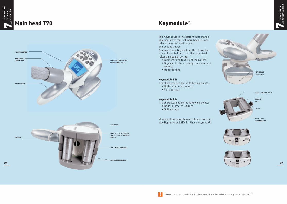
The Keymodule is the bottom interchange-able section of the T70 main head. It com-prises the motorised rollers and sealing valves. You have three Keymodule, the character-istics of which differ from the motorized rollers in several points: • Diameter and texture of the rollers. • Rigidity of return springs on motorised
rollers. • Roller lenght.
Keymodule i 1:It is characterised by the following points: • Roller diameter: 26 mm. • Hard springs.
Keymodule i 2: It is characterised by the following points: • Roller diameter: 28 mm. • Soft springs.
Movement and direction of rotation are visu-ally displayed by LEDs for these Keymodule.
! Before running your unit for the first time, ensure that a Keymodule is properly connected to the T70.
Keymodule®Main head T70
monitor screen
rapid twist connection
main handle
control panel with adjustment keys
trigger
keymodule
safety grid to prevent the ingress of foreign debris
treatment chamber
motorized rollers
electrical contacts
sealing valve
latch
keymodule disconnected
keymodule
connected
7. A d
es
cr
ipt
ion
o
f m
ain
he
ad
t7
0
7. B d
es
cr
ipt
ion
of
ke
ym
od
ul
e
26 27

7. B d
es
cr
ipt
ion
of
ke
ym
od
ul
e
InstallationKeymodule®
Every Keymodule is designed to be compatible with the main head T70.
Attach the Keymodule to the main head as shown in the photos opposite.
To remove the Keymodule release the lat-ches.
Keymodule i 50:is adaptable to the main head of the Cellu M6 Keymodule [2]i T70. It consists of two motorised rollers and airtight val-ves.
It is characterized by the following points: • Roller diameter: 26 mm. • Roller length: 50 mm. • Soft springs. • The depth of treatment can be selec-
ted by setting the rollers a distance of between 28 and 10 mm apart.
electrical contacts
sealing valve
latch
keymodule
disconnected
keymodule
connected
7. B d
es
cr
ipt
ion
of
ke
ym
od
ul
e
28 29
Setting the cursor of keymodule i 1, i 2 and i 50
The Keymodule i1, i2 and i 50 have a cur-sor, which can be adjusted to 5 positions, thereby making it possible to adjust the spacing between the motorized rollers.
When the cursor is in the bottom position (figure 1) the distance between centres of the rollers is maximum and fixed, there is no roller mobility.
When the cursor is in the top position (figure 2) the distance between centres of the rollers is variable, from a maximum position to a minimum position, which ensures maximum mobility of the rollers.
When the cursor is in one of the 3 inter-mediate positions (figure 3) the distance between centres of the rollers, as well as their mobility, are variable.
1 2 3
keymodulei1, i2
keymodulei 50

7. E d
esc
rip
tio
n o
f n
ozz
les
/ m
icr
o h
ead
&li
ft h
ead
s
7. C fu
nc
tio
ns
inc
or
po
ra
ted
in t
he
t70
Micro-nozzles and micro-heads serie 600
31
! These functions are only possible provided the main treatment head has been selected.
Functions incorporated in the main head
Apart from roller speed settings, frequency or treatment mode (Roll’in or Roll’up), the main head also incorporates the Start/Stop and reverse functions and the roller direction indicator.
Start/Stop:Once the pump has been switched on via the START button on the control screen, starting and stopping the treatment can be controlled from the main head:To start treatment, squeeze the trigger briefly.To stop treatment, squeeze the trigger for a longer period. This function can also be enabled via the START/STOP button on the head.
Direction of movement indicator (when the rollers are moving in the same direc-tion):Each squeeze of the trigger reverses the direction the head moves in.Throughout the treatment, the direction of movement of the main head is shown by flashing lights.
Reverse mode and LEDs:In reverse mode (the rollers are turning in opposite directions) the way the LEDs flash becomes more specific:
• in roll’out mode (the 2 rollers roll in the fold), the 2 LEDs are lit and flash,
• in roll’in mode (the 2 rollers roll out the fold), the 2 LEDs stay lit.
trigger support
stop key
forward movement (roll’up)
backward movement (roll’up)
mode roll’inmode roll’out
30
T7 CONVEX
T7 FLAT
T7 CONCAVE
SUPPORT (COMMON TO ALL THE MICRO-NOZZLESAND ALL MICRO-HEADS)
MICRO-NOZZLE N°1 AND 2
TML 10 WITH REMOVABLE FLAPS TML 19 WITH REMOVABLE FLAPS TML 30 WITH REMOVABLE FLAPS
Adjusting the force with which the flaps return:
To guarantee that the flaps return effectively and therefore to optimize treatment, it is important to adjust the knob in line with the intensity of the treatment and the program selected.
• Turn the knob from A to G to increase the flap’s return force.
• Turn the knob from G to A to reduce the flap’s return force.
Lift heads
. D
! This chapter does not apply to Cellu M6 Keymodule i.

7. G fu
nct
ion
s in
corp
or.
in th
e aux
. ada
pter
/ de
scri
ptio
n o
f au
x. h
eads
7. Hm
ain
te
na
nc
e
Cleaning the auxiliary heads
! All the maintenance operations described in this section must be carried out with the unit switched off and the supply cable disconnected. This chapter does not apply to Cellu M6 Keymodule i.
33
! These functions are only possible provided the auxiliary treatment head has been selected.
Functionsincorporated in the auxiliary adapter
32
control
start/stop
to reduce treatmentintensity
to increase treatmentintensity
Because the control is incorporated in the auxiliary head connection, you can start or stop your treatment by operating the START/STOP switch and adjust the treatment inten-sity using the +/- keys without having to go to the control panel of your unit.
Auxiliaryheads serie 600 - active
TYPE: 630A
TYPE: 644ATYPE: 615A
auxiliary adapter withincorporated controls
controls
twist connection
↔
↔
.F
When used for specific purposes such as the after-effects of burns or lymphoedema, the treatment heads must be thoroughly disinfected after use:
1. After following the cleaning procedure described above, soak the head (auxiliary head, micro-head and micro-nozzle) and the rollers in a disinfectant solution for 15 minutes.
2. Rinse carefully.
3. Leave to dry.
Warning: Use a non-alkaline disinfectant that complies with AFNOR standards and has the following microbiological properties: Bactericide (NF EN 1040, NF T 72-171, NF T 72-190, T 72-300/301), Fungicide (NF EN 1275, NF T 72-200).
For reasons of hygiene, the treatment heads should be cleaned before and after each use with the heads disconnected from the machine. Use antiseptic wipes and a bactericidal and fungicidal solution.
Lift head:
1. Before use, clean the flaps and the side plates.
2. After use, remove the flaps from the head for more thorough cleaning. Grasp the flaps between the thumb and index finger and pull them upwards.
3. Next clean the head’s transparent side plates with antiseptic wipes and a bacteri-cidal and fungicidal solution.
Cleaning the lift heads

7. Hm
ain
te
na
nc
e
7. Hm
ain
te
na
nc
e
3534
! Warning: Do not use aggressive products such as acetone, trichloroethylene or surgical spirit or abrasive sponges, ultrasound or UV lamps. Does not apply to the Cellu M6 Keymodule [2] i.
Cleaning the lift heads (cont’d)
4. Clean the flaps in the same way.
5. Once cleaning is complete, refit the flaps by pushing them back into their housing, holding them with the antiseptic wipe.
Removing the TML10 flaps:
The TML10 flaps can be removed and refitted using the special extractor tool.
1. To remove the flaps, hold the extractor tool’s sides in, then release them and pull out both the tool and the flaps.
2. To remove the flaps from the tool, press in on the sides of the tool.
3. Once cleaning is complete, replace the flaps as shown below.
Replacing the flaps/airtight kit
Once the flaps no longer permit proper skin treatment, they should be replaced. Use the flaps provided with the machine or order an airtight kit from the Customer Service of your distributor.
1. TML10 airtight kit.
2. TML19 and TML30 airtight kit.
3. Using the hex key provided in the kit, remove the side plates by unscrewing the two screws and replace them with the new ones.
4. Remove the sealing ring from the treat-ment head connector and replace it with the new one.
3 3
4 4
2
1

7. Hm
ain
te
na
nc
e
Cleaning the main head
Cleaning the main head7. H
ma
int
en
an
ce
3736
Cleaning the Keymodule:
1. Turn the Keymodul and clean the rollers on either side. Manually turn the rollers so as to gain access to the entire surface area.
2. Turn the Keymodule again and refit the sealing valves as shown on the photos.
3. Do not forget to clean the sealing joint between the Keymodule and head body.
4. Check that the electrical contacts are clean and dry and proceed in the reverse sequence to refit the Keymodule onto the main head.
Now check that the head is operating correctly. To do this, operate the head in the palm of your hands to ensure the correct sealing of the treatment chamber and visually inspect the movement of the valves and that of the rollers.
WARNING: if the Keymodule is not fitted to the main head, if it is incorrectly positioned or even faulty, the main head screen will display the icon alongside:
Check the assembly of the Keymodule.
electrical contacts
sealing joint between the head body and the keymodule
For hygiene reasons, the treatment heads must be cleaned after each use, using antiseptic wipes with a bactericidal and fungicidal solution.
Special attention must be paid to those parts coming into contact with the patient.
Cleaning the tightness valves:
1. Release the Keymodule as shown on the photos.
2. Make sure that the cursor is in the top position.
3. Bring the roller to the center.
4. Remove the corresponding sealing valve by handling it as shown on the photo. Repeat this operation for the other valve.
5. Then clean the valves and their location.
Replace the valves after: 100 hours’ operation.
! Do not use aggressive products, such as acetone, trichloroethylene or alcohol at 90°, or abrasive sponges.! Do not use aggressive products, such as acetone, trichloroethylene or alcohol at 90°, or abrasive sponges.

8 w
ar
ra
nt
y
General warranty conditions
39
Cleaning the auxiliary heads micro-heads and micro-nozzles
38
7. Hm
ain
te
na
nc
e
You have recently acquired an appliance dis-tributed by LPG Systems or an LPG Systems approved distributor. It is the purchaser/us-er’s responsibility to find out from the local authorities the conditions and professional qualifications that should be met before us-ing the appliance.
The purchase of this equipment implies the legal acceptance by the purchaser/ profes-sional user of these general warranty condi-tions. If the appliance was sold to you by an approved LPG Systems distributor, the purchaser/user should refer to the sup-plier’s warranty conditions. These may in no way increase the undertakings made in these present warranty conditions. The war-ranty can only be implemented and is only valid if the warranty slip has been duly filled out and returned to LPG Systems within two weeks of delivery, irrespective of the coun-try. Warranty slips that are only partially completed will be rejected.
The appliance is guaranteed against manufacturing flaws and defects in the raw materials. The warranty extends for the shorter of the following two periods: one (1) year OR two thousand (2.000) hours of use from the invoice date. During this period, LPG Systems undertakes to exchange or repair free of charge, as quickly as possible, any part that LPG Systems acknowledges as defective, however LPG Systems does not undertake to replace the entire appli-ance. Traveling and living expenses for our technicians and transportation costs of the appliance or parts to and from the after-sales service workshop are not covered by
this warranty. Replacements and repairs performed within this warranty, with or with-out immobilization of the equipment, shall not have the effect of extending the warranty period. Replaced parts become the property of LPG Systems or the approved distributor. No compensation shall be paid for loss of use. The purchaser/user is required to allow LPG Systems the necessary time and means to carry out all repairs and deliveries of replacement spare parts, Failure to comply will absolve us from our obligations under the warranty.The only courts of competent jurisdiction are those within the legal district of LPG Systems’ head office regardless of any juris-diction clauses in any other document.
Warranty exclusions:
• Damage occurring during transportation. Transportation of this equipment and/or spare parts is at the recipient’s own risk. Before taking delivery, it is the recipi-ent’s responsibility to verify the state of the goods and to make a claim against the transport company in the manner usual in the delivery country.
• Non-observance of the installation and operating instructions, failure to carry out maintenance and/or negligence in maintaining the appliance and/or its filter cartridges, connection to a faulty electricity supply or a non-earthed electricity supply or a power supply whose voltage is differ-ent to the one indicated on the appliance.
For hygiene reasons, the treatment heads must be cleaned after each use, using wipes containing an antiseptic, bactericidal and fungicidal* solution.
Cleaning the auxiliary heads:
1. Disconnect the auxiliary head of the adap-ter for cleaning purposes.
2. Remove the two head rollers to proceed with quick and efficient cleaning as shown on the photograph. For mi-cro-heads, use the micro-head tool supplied.
3. Clean the rollers and the treatment chamber.
4. Refit the rollers and check that they rotate freely.
5. For cleaning the micro-nozzles, use cot-ton swabs containing the same solution.
The Keymodule is a high-technology unit comprising numerous mobile micro-me-chanical parts. The unit must be returned to our Technical Support Center if certain wear
items require replacing.The head may start to lose some of its cha-racteristics at around 1.000 hours of operation.
micro-head tool
* Do not use aggressive products, such as acetone, trichloroethylene or alcohol at 90°, or abrasive sponges.
Overhaul of the Keymodule®
!

8 w
ar
ra
nt
y
To be filled in by the manufacturer
To be completed and return to LPG Systems
Name: ..........................................................................................................................
Adress: ........................................................................................................................
Country:.......................................................................................................................
Tel.: .............................................................................................................................
Type of establishment: ...............................................................................................
Profession: ..................................................................................................................
Type of unit: Cellu M6 Keymodule [2]i Serial number: ………….............................………….
Date: ………………………………….......
LPG SYSTEMS S.A.Technoparc de la Plaine30, rue du docteur Abel - BP n° 3526902 VALENCE Cedex - FranceRCS Romans B 335 183 836
Tel.: +33 (0)4 75 78 69 00 - Fax: +33 (0)4 75 42 80 85
Type of unit: Cellu M6 Keymodule [2]i
To validate the warranty, detach this slip and return to the address below within 15 days following use of the unit:LPG SYSTEMS S.A. - Technoparc de la Plaine
30, rue du docteur Abel - BP n° 35 - 26902 VALENCE Cedex 9 - France
✂
!
8w
ar
ra
nt
y
41
General warranty conditions (cont’d)
Non-compliance with the general guarantee conditions during the term of the warranty and following expiry of the latter, may lead to LPG Systems being exonerated of any liability in the event of damage attributed to the products supplied.
LPG Systems will not be held liable with respect to equipment/material losses or physical accidents (i), following installation that does not comply with the statutory or regulatory provisions of the country where the unit is to be used or (ii) which could
jeopardize a Cellu M6 Keymodule [2] i unit, which was the subject of intervention work not scheduled in the LPG Systems operator’s manual and/or carried out by the operator or a third party not authorized by LPG Systems.
LPG Systems will be absolved of its liability in the event of use exceeding the level of professional competence/qualification of the operator or resulting from the incorrect use of the unit.
• If an appliance is sold before the end of the warranty period, the warranty is trans-ferred to the purchaser for the remaining warranty period, on the condition:
i) that the original invoice is provided,
ii) that the initial vendor is informed of the sale.
• Modification, mounting of accessories or dismantling of the equipment.
• Any operation and/or intervention not specified in the LPG Systems Operating Instructions and performed on the equip-ment by the purchaser/user and/or any
party not approved by LPG Systems.
• Use of consumables, spare parts, inappro-priate components or parts not supplied by LPG Systems.
• Blockage of the appliance through aspira-tion of a foreign body.
• Normal wear and tear of any of the equip-ment’s parts resulting from normal usage.
• Falls, impacts, lightning, fire, force ma-jeure, water damage and natural disasters.
Limitation and exoneration of liability
40

Endermologie® Photo System 9 a
cc
es
so
rie
s
LPG advises patients to wear the “LPG Bodywear” during their treatment sessions. Apart from the advantages relating to its use (resistance, hygiene, respect of privacy, easier working conditions for the practitio-ner) this high quality garment is made of non-abrasive materials and mini-mizes damage from the Keymodule.
It is available in different sizes: - Medium (up to French size 42 or 1 m 70); - Large (over French size 42 or 1 m 70); - Men (one size).
LPG Bodywear is available from the Custo-mer Service of your distributor.
A real high-tech benchmarking and diagnosis tool, Endermologie Photo System enables practitioners to document areas to be treated or respected and to rationalize the results.
Endermologie Photo System puts patients into position in a matter of seconds, and ensures the positions used can be reproduced and compared. In this way, real comparisons can be made, before and after treatment. Digital photography facilitates storage and use of the photographs and respects privacy.
Endermologie Photo System is an essential, logical complement to the LPG Technique.
LPG® Bodywear
42