Embed Size (px)
Citation preview
Configuring ATM Interfaces on Cisco IOS XR Software
This module describes how to configure ATM on the Cisco CRS Router using Cisco IOS XR software. ATM is a cell-switching and multiplexing technology that is widely used in Wide Area Networks (WANs). ATM protocol standards enable point-to-point, point-to-multipoint, and broadcast services connections using various slow- and high-speed network media. Connectivity between two ATM permanent virtual circuits (PVCs) is established using ATM signaling mechanisms. Various ATM signaling standards are defined by these ATM forum standards:
• UNI Version 3.0, Version 3.1, and Version 4.0
• ITU
• IETF
Feature History for Configuring Bidirectional Forwarding Detection on Cisco IOS XR Software
Release Modification
Release 3.7.0 ATM Layer 2 VPN (Port Mode) and QoS was introduced on the following SPAs:
• 3-Port Clear Channel OC-3 ATM SPA
• 1-Port Clear Channel OC-12 ATM SPA
HC-9Cisco IOS XR Interface and Hardware Component Configuration Guide for the Cisco CRS Router
OL-23256-04

Configuring ATM Interfaces on Cisco IOS XR SoftwareContents
Contents• Prerequisites for Implementing ATM, page 10
• Information About ATM, page 11
• Configuring ATM Interfaces, page 18
• ATM Configuration: Examples, page 55
• Additional References, page 63
Prerequisites for Implementing ATMYou must be in a user group associated with a task group that includes the proper task IDs. The command reference guides include the task IDs required for each command. If you suspect user group assignment is preventing you from using a command, contact your AAA administrator for assistance.
Release 3.8.0 Support for ATM over MPLS was added.
Release 3.9.2 Support for ATM UNI (Layer 3 VPN) was added for the following SPAs:
• 1-Port Clear Channel OC-3 ATM SPA
• 3-Port Clear Channel OC-3 ATM SPA
• 1-Port Clear Channel OC-12 ATM SPA
The following ATM UNI features are supported in this release:
• ATM UNI L3 VC termination (UNI 3.0/3.1)
• ILMI
• Per VC QoS
• ATM COS
• MPLS L3VPN per VC sub-interface
• Support for both L2VPN and L3VPN under the same physical interface
• ATM F4/F5 OAM
• MR-APS
• IGP routing with VRF/VPN support: OSPF, BGP, EIGRP, RIP and static
• 150 VC/VP connections per port, maximum VC/VP numbering up to 1024
HC-10Cisco IOS XR Interface and Hardware Component Configuration Guide for the Cisco CRS Router
OL-23256-04

Configuring ATM Interfaces on Cisco IOS XR SoftwareInformation About ATM
Information About ATMThis section provides overviews of these features:
• VC-Class Mapping, page 12
• F5 OAM on ATM Interfaces, page 12
• ILMI on ATM Interfaces, page 13
• Layer 2 VPN on ATM Interfaces, page 13
• ATM Layer 2 QoS, page 15
Network nodes use ATM connections to transfer bits of data organized as 53-byte ATM cells. User information (such as voice, video, and data) is segmented into ATM cells on one end of the connection, and then reassembled on the other end of the connection. ATM Adaptation Layer (AAL) defines the conversion of user information into ATM cells. AAL1 and AAL2 handle isochronous traffic (such as voice and video), and are relevant to the ATM node only when it is equipped with either a CES (Circuit Emulation Service) ATM interface card, or when it has voice over AAL2 capabilities. AAL3/4 and AAL5 support data communications; that is, they segment and reassemble data packets.
The two types of devices in an ATM network are switches and routers. Typically, ATM switches do packet switching at Layer 2, while ATM routers do packet switching using Layer 3 addresses, such as IPv4 network addresses, IPv6 network addresses, and MPLS labels.
ATM is supported on the following line cards:
• Cisco 1-port Clear Channel OC-3 SPA
• Cisco 3-port Clear Channel OC-3 SPA
• Cisco 1-port Clear Channel OC-12 SPA
Cisco IOS XR software ATM interfaces can operate in the following modes:
• Point-to-point
• Layer 2 port mode
Note A single ATM interface can simultaneously support point-to-point and L2VPN subinterfaces.
In Cisco IOS XR software, ATM interface configuration is hierarchical and comprises the following elements:
1. The ATM main interface, which is the physical interface. ATM main interfaces can be configured with point-to-point subinterfaces, vp-tunnels, ILMI interfaces, or as Layer 2 port mode attachment circuits (ACs) or Layer 2 subinterface ACs.
2. ATM subinterfaces, which are configured under the ATM main interface. An ATM subinterface does not actively carry traffic until you configure a PVC or PVP under the ATM subinterface.
3. PVCs, which are configured under an ATM subinterface. A single PVC is allowed per subinterface. PVCs are supported under point-to-point and Layer 2 subinterfaces.
4. Permanent virtual paths (PVPs), which are configured under a Layer 2 ATM subinterface. A single PVP is allowed per subinterface.
HC-11Cisco IOS XR Interface and Hardware Component Configuration Guide for the Cisco CRS Router
OL-23256-04

Configuring ATM Interfaces on Cisco IOS XR SoftwareInformation About ATM
VC-Class MappingA virtual circuit (VC) class enables the configuration of VC parameters that are then mapped to a main interface, subinterface, or PVC. Without vc-classes, you must perform considerable manual configuration on each ATM main interface, subinterface, and PVC and on the router. This configuration can be time consuming and error prone. After you have created vc-class, you can apply that vc-class to as many ATM interfaces, subinterfaces, or PVCs as you want.
Vc-classes include the following types of configuration data:
• ATM encapsulation for the VC
• OAM management
• traffic shaping
The order of configuration precedence is hierarchical, as demonstrated in the following list, where configuration on the PVC takes the highest precedence, and configuration on a vc-class that is attached to the ATM main interface takes the lowest precedence:
1. Configuration on the PVC
2. Configuration on a vc-class that is attached to the PVC
3. Configuration on the subinterface
4. Configuration on a vc-class that is attached to the subinterface
5. Configuration on the ATM main interface
6. Configuration on a vc-class that is attached to the ATM main interface
For example, if the a PVC has unspecified bit rate (UBR) traffic shaping configured, but it is attached to a class map that is configure with CBR traffic shaping, the PVC maintains the UBR traffic shaping.
Note Vc-classes are not applicable to Layer 2 port mode ACs and Layer 2 PVPs. For Layer 2 VPN configurations, Vc-classes are applicable to the PVC only.
F5 OAM on ATM Interfaces The F5 Operation, Administration, and Maintenance (OAM) feature performs fault-management and performance-management functions on PVCs. If the F5 OAM feature is not enabled on a PVC, then that PVC remains up on the end device in the event of a service disruption where network connectivity is lost. The result is that routing entries that point to the connection remain in the routing table and, therefore, packets are lost. The F5 OAM feature detects such failures and brings the PVC down if there is a disruption along its path.
Use the oam-pvc manage command to enable the F5OAM feature on a PVC. After OAM is enabled on a PVC, the PVC can generate F5 loopback cells and you can configure continuity check (CC) management for the PVC. Use the oam ais-rdi and oam retry commands to configure continuity checking on a PVC.
To drop all current and future OAM cells received on an ATM interface, use the atm oam flush command in interface configuration mode.
Note The oam ais-rdi and oam retry commands take effect only after OAM management is enabled on a PVC with the oam-pvc manage command.
HC-12Cisco IOS XR Interface and Hardware Component Configuration Guide for the Cisco CRS Router
OL-23256-04

Configuring ATM Interfaces on Cisco IOS XR SoftwareInformation About ATM
ILMI on ATM InterfacesThe ILMI protocol is defined by the ATM Forum for setting and capturing physical layer, ATM layer, virtual path, and virtual circuit parameters on ATM interfaces. When two ATM interfaces run the ILMI protocol, they exchange ILMI packets across the physical connection. These packets consist of SNMP messages as large as 484 octets. ATM interfaces encapsulate these messages in an ATM adaptation layer 5 (AAL5) trailer, segment the packet into cells, and schedule the cells for transmission.
You must enable ILMI on ATM interfaces that communicate with end devices that are configured for ILMI. To enable ILMI, create a PVC with ILMI encapsulation directly under the main ATM interface by using the pvc vpi/vci ilmi command in interface configuration mode.
PVCs use ILMI encapsulation to carry ILMI messages. Use the pvc vpi/vci ilmi command in interface configuration mode to create an ILMI PVC on an ATM main interface.
Note You must use the same VPI and VCI values on both ends of the PVC that connects the end device and the router.
Note The ILMI configuration commands are available only after an ILMI PVC is created under the ATM main interface. The ILMI configuration takes effect on the ATM main interface.
Note ILMI configuration is not supported on Layer 2 port mode ACs.
Layer 2 VPN on ATM InterfacesThe Layer 2 VPN (L2VPN) feature enables the connection between different types of Layer 2 attachment circuits and pseudowires, allowing users to implement different types of end-to-end services.
Cisco IOS XR software supports a point-to-point, end-to-end service, where two ATM ACs are connected together.
Switching can take place in two ways:
• AC-to-PW—Traffic reaching the PE is tunneled over a pseudowire (and conversely, traffic arriving over the PW is sent out over the AC). This is the most common scenario.
• Local switching—Traffic arriving on one AC is immediately sent out another AC without passing through a pseudowire.
Keep the following in mind when configuring L2VPN on an ATM interface:
• Cisco IOS XR software supports up to 2000 ACs per line card.
• ATM-over-MPLS supports two types of cell encapsulation:
– AAL5 CPCS mode—Unsegmented ATM cells are transported across an MPLS backbone.
– ATM cell (AAL0) mode—Cells are segmented and then reassembled, or packed. AAL0 is supported on ATM main ports, PVCs, and PVPs. The benefits of using AAL0 mode is that groups of ATM cells share a label that maximizes bandwidth efficiencies.
Note AAL5 mode is supported on PVCs only.
HC-13Cisco IOS XR Interface and Hardware Component Configuration Guide for the Cisco CRS Router
OL-23256-04

Configuring ATM Interfaces on Cisco IOS XR SoftwareInformation About ATM
Use the following commands to display AC and pseudowire information:
• show interfaces
• show l2vpn xconnect
• show atm pvp
• show atm pvc
Note For detailed information about configuring an L2VPN network, see the Implementing MPLS Layer 2 VPNs module of Cisco IOS XR Multiprotocol Label Switching Configuration Guide.
Cell Packing on L2VPN ACs with AAL0 Mode Encapsulation
Cell packing is supported on L2VPN ATM interfaces that are configured with AAL0 mode encapsulation. Cell packing relates to the delay variations that are defined in the ATM standards. Users can specify the number of cells that can be processed by the pseudowire, and configure the maximum cell packing timeout (MCPT) timers to use in conjunction with cell packing.
The cell-packing command allows the user to perform the following tasks:
• Configure the maximum number of cells that can be transmitted in a single packet
• Attach one of the three MCPT timers to an individual Layer 2 port mode AC, PVC, or PVP.
The three MCPT timers are defined under the main ATM interface with the atm mcpt-timer command, which lets the user specify the maximum number of microseconds to wait to complete cell packing on a single packet before that packet is transmitted. If the associated MCPT timer expires before the maximum number of cells that can be packed is reached, then the packet is transmitted with the number of cells that have been packed thus far.
We recommend configuring a low, medium, and high value for the three MCPT timers to accommodate the different ATM traffic classes. Low- latency constant bit rate (CBR) traffic typically uses a low MCPT timer value, while high-latency Unspecified bit rate (UBR) traffic typically requires a high MCPT timer value. Variable bit rate real-time (VBR-rt) and variable bit rate non-real-time (VBR-nrt) traffic typically use a median MCPT timer value.
HC-14Cisco IOS XR Interface and Hardware Component Configuration Guide for the Cisco CRS Router
OL-23256-04

Configuring ATM Interfaces on Cisco IOS XR SoftwareInformation About ATM
ATM Layer 2 QoS QoS is configured on ATM interfaces primarily in the same way that it is configured on other interfaces. No new CLIs are added in this release.
For complete information on configuring QoS and QoS commands, refer to these documents:
• Cisco IOS XR Modular Quality of Service Configuration Guide for the Cisco CRS Router
• Cisco IOS XR Modular Quality of Service Command Reference for the Cisco CRS Router
This section describes the features and restrictions that apply to ATM Layer 2 QoS.
Features
These QoS features are supported:
• Layer 2 Ingress QoS – policing, marking, and queueing are supported
• Layer 2 Egress Main Interface QoS – shaping, policing, and queueing are supported. Marking is not supported. This feature works on both Layer 2 and Layer 3 PVCs independent of any subinterface QoS policies.
• The Modular QoS CLI (MQC) actions are supported for ATM traffic in the ingress direction only.
– match atm clp
– match atm oam
– set atm clp
– set mpls exp imp
– set prec tunnel (L2TPv3 only)
– set dscp tunnel (L2TPv3 only)
• Traffic is classified based on Cell Loss Priority–CLP1, CLP0, or OAM.
• OAM traffic can be excluded from policing by using the match-oam classification in a hierarchical policy map
• The following set actions are supported:
– set mpls exp imp
– set prec tunnel
– set dscp tunnel
– set qos-group
– set disc-class
– set atm-clp (exceed action only)
• Policy map counters are supported.
Matching
The following match criteria is supported on Layer 2 ATM interfaces in the ingress direction only:
• match atm clp0
• match atm clp1
• match atm oam
HC-15Cisco IOS XR Interface and Hardware Component Configuration Guide for the Cisco CRS Router
OL-23256-04

Configuring ATM Interfaces on Cisco IOS XR SoftwareInformation About ATM
The following match criteria is supported on Layer 2 ATM interfaces in the egress direction only:
• match mpls exp topmost (egress only)
• match qos-group (egress only)
Note The match-all command does not support the above match criteria.
Marking
The following marking actions are supported on Layer 2 ATM interfaces:
• set mpls exp imposition (AToM only)
• set qos-group (AToM and local switching)
• set discard-class (AToM and local switching)
• set mpls exp imposition and set atm-clp (AToM only)
• set tunnel-dscp (L2TPv3 only)
• set tunnel-prec (L2TPv3 only)
Note Packets can be matched and remarked for CLP0, CLP1, and OAM.
Policing
Policing is supported on Layer 2 ATM interfaces in the ingress direction only.
Policing is performed during segmentation and reassembly (SAR) for the following ATM traffic classes:
• CBR.1
• VBR.1
• VBR.2
• VBR.3
• UBR.1
• UBR.2
Policing is supported for VC and VP modes, but not for Port mode L2 ATM interfaces.
OAM cells are policed along with the user cells unless the QOS policy is explicitly configured to exclude OAM cells from being policed. This can be achieved using different match criteria in the policy map with class-default matching all the traffic including OAM cells.
Policing is supported for ATM AAL5SNAP, AAL5MUX and AAL5NLPID encapsulated packets.
Policing is done on AAL0 packets with the same conditions as AAL5 packets as follows:
• AAL5 packet is conforming if all the cells in the packet conform to PCR and SCR buckets.
• AAL5 packet is exceeding if at least one cell does not conform to the SCR bucket.
• AAL5 packet is violating if at least one cell does not conform to the PCR bucket.
HC-16Cisco IOS XR Interface and Hardware Component Configuration Guide for the Cisco CRS Router
OL-23256-04

Configuring ATM Interfaces on Cisco IOS XR SoftwareInformation About ATM
Note The Martini Control Word C bit is set for all exceeding AAL5 packets. All violating AAL5 packets are dropped.
The following policing options are supported for ATM TM4.0 GCRA policing:
• Rate in cellsps and percent
• Peak rate in cellsps and percent
• Delay tolerance in us
• Maximum burst size in cells
The following conform and exceed actions are supported for Layer 2 ATM interfaces in the ingress direction:
• transmit
• drop
• set mpls exp imposition (AToM only)
• set qos-group (AToM and Local switching)
• set discard-class (AToM and Local switching)
• set atm-clp (exceed action only, AToM and Local switching)
• set tunnel-prec (L2TPv3 only)
• set tunnel-dscp (L2TPv3 only)
Note The only violate action that is supported is the drop action.
The following combination of multiple policing actions is supported:
• set mpls exp imposition and set atm-clp (exceed action only, AToM only)
Hierarchical Policy Maps
For VBR.2 and VBR.3 traffic classes, 2-level hierarchical policy maps are supported in the ingress direction only. Attempts to attach hierarchical policy maps in the egress direction are denied.
The parent policy contains the policing configuration for the PCR bucket and matches on all traffic. The parent policy may exclude OAM traffic.
The child policy contains the policing configuration for the SCR bucket and typically matches on CLP0 cells.
Marking actions are supported only in child policy maps. All other policing actions are allowed in parent policy maps.
Only two policing buckets per Layer 2 circuit are allowed; one in the parent policy that defines the peak rate, and one in the child policy that defines the SCR.
Typically CLP0 cells are sent to the SCR bucket, but it is possible to send both CLP0 and CLP1 cells to the SCR bucket, using the classification criteria in the child policy.
Note For ATM Layer 2 QoS, in policy maps, the set atm-clp command is supported only as a police exceed action. It is not supported as a standalone set action.
HC-17Cisco IOS XR Interface and Hardware Component Configuration Guide for the Cisco CRS Router
OL-23256-04

Configuring ATM Interfaces on Cisco IOS XR SoftwareConfiguring ATM Interfaces
Configuring ATM InterfacesThe ATM interface configuration tasks are described in the following procedures:
• Bringing Up an ATM Interface, page 18
• Configuring Optional ATM Interface Parameters, page 20
• How to Create and Configure a Point-to-Point ATM Subinterface with a PVC, page 23
– Creating a Point-to-Point ATM Subinterface with a PVC, page 23
– Configuring Optional Point-to-Point ATM PVC Parameters, page 25
• How to Configure a Layer 2 Attachment Circuit, page 28
– Creating a Layer 2 Port Mode AC, page 28
– Configuring Optional Parameters on a Layer 2 Port Mode AC, page 30
– Creating an ATM Layer 2 Subinterface with a PVC, page 31
– Configuring Optional ATM Layer 2 PVC Parameters, page 33
– Creating an ATM Layer 2 Subinterface with a PVP, page 36
– Configuring Optional ATM Layer 2 PVP Parameters, page 37
• How to Create and Configure a VC-Class, page 39
– Creating and Configuring a VC-Class, page 40
– Attaching a VC-Class to a Point-to-Point ATM Main Interface, page 43
– Attaching a VC-Class to a Point-to-Point ATM Subinterface, page 44
– Attaching a VC-Class to a PVC on an ATM Subinterface, page 45
• How to Configure ILMI on ATM Interfaces, page 47
– Enabling ILMI on an ATM Interface, page 47
– Disabling ILMI on an ATM Interface, page 49
• Attaching a Service-Policy to an Attachment Circuit, page 52
Bringing Up an ATM InterfaceThis task describes the commands used to bring up an ATM interface.
Restrictions
The configuration on both ends of the ATM connection must match for the interface to be active.
SUMMARY STEPS
1. configure
2. interface atm interface-path-id
3. no shutdown
4. endorcommit
HC-18Cisco IOS XR Interface and Hardware Component Configuration Guide for the Cisco CRS Router
OL-23256-04

Configuring ATM Interfaces on Cisco IOS XR SoftwareConfiguring ATM Interfaces
5. exit
6. exit
7. Repeat Step 1 through Step 6 to bring up the interface at the other end of the connection.
8. show interfaces atm interface-path-id brief
DETAILED STEPSs
Command or Action Purpose
Step 1 configure
Example:RP/0/RP0/CPU0:router# configure
Enters global configuration mode.
Step 2 interface atm interface-path-id
Example:RP/0/RP0/CPU0:router (config)# interface atm 0/6/0/1
Enters ATM interface configuration mode.
Step 3 no shutdown
Example:RP/0/RP0/CPU0:router (config-if)# no shutdown
Removes the shutdown configuration.
Note Removal of the shutdown configuration eliminates the forced administrative down on the interface, enabling it to move to an up or down state.
Step 4 end
or
commit
Example:RP/0/RP0/CPU0:router (config-if)# end
or
RP/0/RP0/CPU0:router(config-if)# commit
Saves configuration changes.
• When you issue the end command, the system prompts you to commit changes:
Uncommitted changes found, commit them before exiting(yes/no/cancel)? [cancel]:
– Entering yes saves configuration changes to the running configuration file, exits the configuration session, and returns the router to EXEC mode.
– Entering no exits the configuration session and returns the router to EXEC mode without committing the configuration changes.
– Entering cancel leaves the router in the current configuration session without exiting or committing the configuration changes.
• Use the commit command to save the configuration changes to the running configuration file and remain within the configuration session.
Step 5 exit
Example:RP/0/RP0/CPU0:router (config-if)# exit
Exits interface configuration mode and enters global configuration mode.
HC-19Cisco IOS XR Interface and Hardware Component Configuration Guide for the Cisco CRS Router
OL-23256-04

Configuring ATM Interfaces on Cisco IOS XR SoftwareConfiguring ATM Interfaces
What to Do Next
• To modify the default configuration of the ATM interface you just brought up, see the “Configuring Optional ATM Interface Parameters” section on page 20.
• To configure a point-to-point subinterface on the ATM interface you just brought up, see the “How to Create and Configure a Point-to-Point ATM Subinterface with a PVC” section on page 23.
• To create a vp-tunnel on the ATM interface you just brought up, see the “How to Configure a Layer 2 Attachment Circuit” section on page 28.
• To use the interface as a Layer 2 post mode AC, see the “How to Configure a Layer 2 Attachment Circuit” section on page 28.
• To attach a Vc-class to the ATM interface you just brought up, see the “How to Create and Configure a VC-Class” section on page 39.
• To enable ILMI on the ATM interface you just brought up, see the “How to Configure ILMI on ATM Interfaces” section on page 47.
Configuring Optional ATM Interface ParametersThis task describes the commands you can use to modify the default configuration on an ATM interface.
Prerequisites
Before you modify the default ATM interface configuration, we recommend that you bring up the ATM interface and remove the shutdown configuration, as described in the “Bringing Up an ATM Interface” section on page 18.
Restrictions
The configuration on both ends of the ATM connection must match for the interface to be active.
Step 6 exit
Example:RP/0/RP0/CPU0:router (config)# exit
Exits global configuration mode and enters EXEC mode.
Step 7 Repeat Step 1 through Step 6 to bring up the interface at the other end of the connection.
Brings up the connection.
Note The configuration on both ends of the ATM connection must match.
Step 8 show interfaces atm interface-path-id brief
Example:RP/0/RP0/CPU0:router# show interfaces atm 0/6/0/1 brief
(Optional) Verifies that the interface is active and properly configured.
If you have brought up an ATM interface properly, the“Intf State” field for that interface in the show interfaces atm command output shows “up.”
Command or Action Purpose
HC-20Cisco IOS XR Interface and Hardware Component Configuration Guide for the Cisco CRS Router
OL-23256-04

Configuring ATM Interfaces on Cisco IOS XR SoftwareConfiguring ATM Interfaces
SUMMARY STEPS
1. configure
2. interface atm interface-path-id
3. atm maxvpi-bits 12
4. atm oam flush
5. atm mcpt-timers timer-1 timer-2 timer-3
6. endorcommit
7. exit
8. exit
9. show atm interface atm [interface-path-id]
10. show interfaces atm interface-path-id brief
Command or Action Purpose
Step 1 configure
Example:RP/0/RP0/CPU0:router# configure
Enters global configuration mode.
Step 2 interface atm interface-path-id
Example:RP/0/RP0/CPU0:router (config)# interface atm 0/6/0/1
Enters ATM interface configuration mode.
Step 3 atm maxvpi-bits 12
Example:RP/0/RP0/CPU0:router (config-if)# atm maxvpi-bits 12
(Optional) Enables support for the 12-bit VPI NNI cell format.
Step 4 atm oam flush
Example:RP/0/RP0/CPU0:router (config-if)# atm oam flush
(Optional) Drops all current and future OAM cells received on an ATM interface.
Step 5 atm mcpt-timers timer-1 timer-2 timer-3
Example:RP/0/RP0/CPU0:router (config-if)# atm mcpt-timers 50 100 200
(Optional) Specifies the maximum cell packing timeout values for each of the three per-interface MCPT timers, in microseconds.
Note The default value for each timer is 50 microseconds.
Note The atm mcpt-timers command is applicable to Layer 2 ATM ACs only.
HC-21Cisco IOS XR Interface and Hardware Component Configuration Guide for the Cisco CRS Router
OL-23256-04

Configuring ATM Interfaces on Cisco IOS XR SoftwareConfiguring ATM Interfaces
What to Do Next
• To configure a point-to-point subinterface on the ATM interface you just brought up, see the “How to Create and Configure a Point-to-Point ATM Subinterface with a PVC” section on page 23.
• To create a vp-tunnel on the ATM interface you just brought up, see the “How to Configure a Layer 2 Attachment Circuit” section on page 28.
• To use the interface as a Layer 2 ATM AC, see the “How to Configure a Layer 2 Attachment Circuit” section on page 28.
Step 6 end
or
commit
Example:RP/0/RP0/CPU0:router (config-if)# end
or
RP/0/RP0/CPU0:router(config-if)# commit
Saves configuration changes.
• When you issue the end command, the system prompts you to commit changes:
Uncommitted changes found, commit them before exiting(yes/no/cancel)? [cancel]:
– Entering yes saves configuration changes to the running configuration file, exits the configuration session, and returns the router to EXEC mode.
– Entering no exits the configuration session and returns the router to EXEC mode without committing the configuration changes.
– Entering cancel leaves the router in the current configuration session without exiting or committing the configuration changes.
• Use the commit command to save the configuration changes to the running configuration file and remain within the configuration session.
Step 7 exit
Example:RP/0/RP0/CPU0:router (config-if)# exit
Exits interface configuration mode and enters global configuration mode.
Step 8 exit
Example:RP/0/RP0/CPU0:router (config)# exit
Exits global configuration mode and enters EXEC mode.
Step 9 show atm interface atm [interface-path-id]
Example:RP/0/RP0/CPU0:router# show atm interface atm 0/6/0/1
(Optional) Displays ATM-specific data for the specified ATM interface.
Step 10 show interfaces atm interface-path-id
Example:RP/0/RP0/CPU0:router# show interfaces atm 0/6/0/1
(Optional) Displays general information for the specified ATM interface.
Command or Action Purpose
HC-22Cisco IOS XR Interface and Hardware Component Configuration Guide for the Cisco CRS Router
OL-23256-04

Configuring ATM Interfaces on Cisco IOS XR SoftwareConfiguring ATM Interfaces
• To attach a Vc-class to the ATM interface you just brought up, see the “How to Create and Configure a VC-Class” section on page 39.
• To enable ILMI on the ATM interface you just brought up, see the “How to Configure ILMI on ATM Interfaces” section on page 47.
How to Create and Configure a Point-to-Point ATM Subinterface with a PVCThe configuration tasks for creating and configuring a point-to-point ATM subinterface with a PVC are described in the following procedures:
• Creating a Point-to-Point ATM Subinterface with a PVC, page 23
• Configuring Optional Point-to-Point ATM PVC Parameters, page 25
Creating a Point-to-Point ATM Subinterface with a PVCThe procedure in this section creates a point-to-point ATM subinterface and configures a permanent virtual circuit (PVC) on that ATM subinterface.
Prerequisites
Before you can create an ATM subinterface on an ATM interface, you must bring up an ATM interface, as described in the “Bringing Up an ATM Interface” section on page 18.
Restrictions
Only one PVC can be configured for each point-to-point ATM subinterface.
SUMMARY STEPS
1. configure
2. interface atm interface-path-id.subinterface point-to-point
3. ipv4 address ipv4_address/prefix
4. pvc vpi/vci
5. endorcommit
6. Repeat Step 1 through Step 5 to bring up the ATM subinterface and any associated PVC at the other end of the connection.
HC-23Cisco IOS XR Interface and Hardware Component Configuration Guide for the Cisco CRS Router
OL-23256-04

Configuring ATM Interfaces on Cisco IOS XR SoftwareConfiguring ATM Interfaces
DETAILED STEPS
Command or Action Purpose
Step 1 configure
Example:RP/0/RP0/CPU0:router# configure
Enters global configuration mode.
Step 2 interface atm interface-path-id.subinterface point-to-point
Example:RP/0/RP0/CPU0:router (config)# interface atm 0/6/0/1.10
Enters ATM subinterface configuration mode.
Step 3 ipv4 address ipv4_address/prefix
Example:RP/0/RP0/CPU0:router (config-subif)#ipv4 address 10.46.8.6/24
Assigns an IP address and subnet mask to the subinterface.
Step 4 pvc vpi/vci
Example:RP/0/RP0/CPU0:router (config-subif)# pvc 5/10
(Optional) Creates an ATM permanent virtual circuit (PVC) and enters ATM PVC configuration submode.
Note Only one PVC is allowed per subinterface.
Step 5 end
or
commit
Example:RP/0/RP0/CPU0:router (config-subif)# end
or
RP/0/RP0/CPU0:router(config-subif)# commit
Saves configuration changes.
• When you issue the end command, the system prompts you to commit changes:
Uncommitted changes found, commit them before exiting(yes/no/cancel)? [cancel]:
– Entering yes saves configuration changes to the running configuration file, exits the configuration session, and returns the router to EXEC mode.
– Entering no exits the configuration session and returns the router to EXEC mode without committing the configuration changes.
– Entering cancel leaves the router in the current configuration session without exiting or committing the configuration changes.
• Use the commit command to save the configuration changes to the running configuration file and remain within the configuration session.
Step 6 Repeat Step 1 through Step 5 to bring up the ATM subinterface and any associated PVC at the other end of the connection.
Brings up the ATM connection.
Note The configuration on both ends of the subinterface connection must match.
HC-24Cisco IOS XR Interface and Hardware Component Configuration Guide for the Cisco CRS Router
OL-23256-04

Configuring ATM Interfaces on Cisco IOS XR SoftwareConfiguring ATM Interfaces
What to Do Next
• To configure optional PVC parameters, see the “Configuring Optional Point-to-Point ATM PVC Parameters” section on page 25.
• To attach Layer 3 service policies, such as Multiprotocol Label Switching (MPLS) or quality of service (QoS), to the PVC under the PVC submode, refer to the appropriate Cisco IOS XR software configuration guide.
• To configure a vc-class and apply it to an ATM subinterface or PVC, see the “Creating and Configuring a VC-Class” section on page 40.
Configuring Optional Point-to-Point ATM PVC ParametersThis task describes the commands you can use to modify the default configuration on an ATM PVC.
Prerequisites
Before you can modify the default PVC configuration, you must create the PVC on an ATM subinterface, as described in the “Creating a Point-to-Point ATM Subinterface with a PVC” section on page 23.
Restrictions
The configuration on both ends of the PVC must match for the connection to be active.
SUMMARY STEPS
1. configure
2. interface atm interface-path-id.subinterface point-to-point
3. pvc vpi/vci
4. encapsulation {aal5mux ipv4 | aal5nlpid | aal5snap}
5. oam-pvc manage [frequency] [disable] [keep-vc-up [seg-aisrdi-failure]]
6. oam ais-rdi [down-count [up-count]]
7. oam retry
8. shape [cbr peak_output_rate | ubr peak_output_rate | vbr-nrt peak_output_rate sustained_output_rate burst_size| vbr-rt peak_output_rate sustained_output_rate burst_size]
9. service-policy [input | output] policy_name
10. endorcommit
11. Repeat Step 1 through Step 10 to configure the PVC at the other end of the connection.
HC-25Cisco IOS XR Interface and Hardware Component Configuration Guide for the Cisco CRS Router
OL-23256-04

Configuring ATM Interfaces on Cisco IOS XR SoftwareConfiguring ATM Interfaces
DETAILED STEPS
Command or Action Purpose
Step 1 configure
Example:RP/0/RP0/CPU0:router# configure
Enters global configuration mode.
Step 2 interface atm interface-path-id.subinterface point-to-point
Example:RP/0/RP0/CPU0:router (config)# interface atm 0/6/0/1.10 point-to-point
Enters ATM subinterface configuration mode.
Step 3 pvc vpi/vci
Example:RP/0/RP0/CPU0:router (config-subif)# pvc 5/10
Enters subinterface configuration mode for the PVC.
Step 4 encapsulation {aal5mux ipv4 | aal5nlpid | aal5snap}
Example:RP/0/RP0/CPU0:router (config-atm-vc)# encapsulation aal5snap
Configures the ATM adaptation layer (AAL) and encapsulation type for a PVC.
Note The default encapsulation type for a vc-class is AAL5/SNAP
Step 5 oam-pvc manage [frequency] [disable] [keep-vc-up [seg-aisrdi-failure]
Example:RP/0/RP0/CPU0:router (config-atm-vc)# oam-pvc manage 200 keep-vc-up
Enable ATM OAM F5 loopback cell generation and configures continuity check (CC) management for the ATM permanent virtual circuit (PVC).
• Include the disable keyword to disable OAM management on the specified PVC.
• Include the keep-vc-up keyword specify that PVC remains in the UP state when CC cells detect connectivity failure.
• Include the seg-aisrdi-failure keyword to specify that, if segment AIS/RDI cells are received, the VC will not be brought down because of end CC failure or loopback failure.
Step 6 oam ais-rdi [down-count [up-count]]
Example:RP/0/RP0/CPU0:router (config-atm-vc)# oam ais-rdi 25 5
Configures the PVC so that it is brought down after a specified number of OAM alarm indication signal/remote defect indication (AIS/RDI) cells are received on the associated PVC.
Step 7 oam retry [up-count [down-count [retry-frequency]]]
Example:RP/0/RP0/CPU0:router (config-atm-vc)# oam retry 5 10 5
Configures parameters related to OAM management for the PVC.
If no OAM AIS/RDI cells are received within the specified interval, the PVC is brought up.
HC-26Cisco IOS XR Interface and Hardware Component Configuration Guide for the Cisco CRS Router
OL-23256-04

Configuring ATM Interfaces on Cisco IOS XR SoftwareConfiguring ATM Interfaces
What to Do Next
• To attach Layer 3 service policies, such as MPLS or QoS, to the PVC under the PVC submode, refer to the appropriate Cisco IOS XR software configuration guide.
• To configure a vc-class and apply it to an ATM subinterface or PVC, see the “Creating and Configuring a VC-Class” section on page 40.
Step 8 shape [cbr peak_output_rate | ubr peak_output_rate| vbr-nrt peak_output_rate sustained_output_rate burst_size| vbr-rt peak_output_rate sustained_output_rate burst_size]
Example:RP/0/RP0/CPU0:router (config-atm-vc)# shape vbr-nrt 100000 100000 8000
Configures ATM traffic shaping for the PVC.
You must estimate how much bandwidth is required before you configure ATM traffic shaping.
• peak_output_rate—Configures the maximum cell rate that is always available for the traffic.
• Sustained_output_rate—Sustained output rate for the bit rate.
• burst size—Burst cell size for the bit rate. Range is from 1 through 8192.
Step 9 service-policy [input | output] policy_name
Example:RP/0/RP0/CPU0:router (config-atm-vc)# service-policy input policyA
Attaches a QoS policy to an input or output PVC. Replace policy_name with the name of the service policy you want to attach to the PVC.
Note For information on creating and configuring service policies, see the Cisco IOS XR Modular Quality of Service Configuration Guide.
Step 10 end
or
commit
Example:RP/0/RP0/CPU0:router (config-subif)# end
or
RP/0/RP0/CPU0:router(config-subif)# commit
Saves configuration changes.
• When you issue the end command, the system prompts you to commit changes:
Uncommitted changes found, commit them before exiting(yes/no/cancel)? [cancel]:
– Entering yes saves configuration changes to the running configuration file, exits the configuration session, and returns the router to EXEC mode.
– Entering no exits the configuration session and returns the router to EXEC mode without committing the configuration changes.
– Entering cancel leaves the router in the current configuration session without exiting or committing the configuration changes.
Use the commit command to save the configuration changes to the running configuration file and remain within the configuration session.
Step 11 Repeat Step 1 through Step 10 to configure the PVC at the other end of the connection.
Brings up the connection.
Note The configuration on both ends of the connection must match.
Command or Action Purpose
HC-27Cisco IOS XR Interface and Hardware Component Configuration Guide for the Cisco CRS Router
OL-23256-04

Configuring ATM Interfaces on Cisco IOS XR SoftwareConfiguring ATM Interfaces
How to Configure a Layer 2 Attachment CircuitThe Layer 2 AC configuration tasks are described in the following procedures:
• Creating a Layer 2 Port Mode AC
• Configuring Optional Parameters on a Layer 2 Port Mode AC
• Creating an ATM Layer 2 Subinterface with a PVC
• Configuring Optional ATM Layer 2 PVC Parameters
• Creating an ATM Layer 2 Subinterface with a PVP
• Configuring Optional ATM Layer 2 PVP Parameters
Note After you configure an interface for Layer 2 switching, no routing commands such as ipv4 address are permissible. If any routing commands are configured on the interface, then the l2transport command is rejected.
Creating a Layer 2 Port Mode ACThe procedure in this section creates a Layer 2 port mode AC.
Prerequisites
Before you can create a Layer 2 port mode AC, you must bring up an ATM main interface, as described in the “Bringing Up an ATM Interface” section on page 18.
Restrictions
ILMI configuration is not supported on Layer 2 port mode ACs.
Restrictions
Before you can configure an Layer 2 port mode AC, you must ensure that no configuration, such as subinterfaces, already exists on that port. If any preconfiguration does exist, you must remove it.
SUMMARY STEPS
1. configure
2. interface atm interface-path-id
3. l2transport
4. endorcommit
5. Repeat Step 1 through Step 4 to bring up the ATM AC at the other end of the connection.
HC-28Cisco IOS XR Interface and Hardware Component Configuration Guide for the Cisco CRS Router
OL-23256-04

Configuring ATM Interfaces on Cisco IOS XR SoftwareConfiguring ATM Interfaces
DETAILED STEPS
What to Do Next
• To configure a point-to-point pseudowire XConnect on the Layer 2 port mode AC you just created, see the Implementing MPLS Layer 2 VPNs module of Cisco IOS XR Multiprotocol Label Switching Configuration Guide.
• To configure optional Layer 2 VPN parameters for the ATM AC, see the “Configuring Optional Parameters on a Layer 2 Port Mode AC” section on page 30.
Command or Action Purpose
Step 1 configure
Example:RP/0/RP0/CPU0:router# configure
Enters global configuration mode.
Step 2 interface atm interface-path-id
Example:RP/0/RP0/CPU0:router (config)# interface atm 0/6/0/1
Enters interface configuration mode for an ATM interface.
Step 3 l2transport
Example:RP/0/RP0/CPU0:router (config-if)# l2transport
Enters ATM Layer 2 transport configuration mode, and enables Layer 2 port mode on this ATM interface.
Step 4 end
or
commit
Example:RP/0/RP0/CPU0:router (config-if-l2)# end
or
RP/0/RP0/CPU0:router(config-if-l2)# commit
Saves configuration changes.
• When you issue the end command, the system prompts you to commit changes:
Uncommitted changes found, commit them before exiting(yes/no/cancel)? [cancel]:
– Entering yes saves configuration changes to the running configuration file, exits the configuration session, and returns the router to EXEC mode.
– Entering no exits the configuration session and returns the router to EXEC mode without committing the configuration changes.
– Entering cancel leaves the router in the current configuration session without exiting or committing the configuration changes.
• Use the commit command to save the configuration changes to the running configuration file and remain within the configuration session.
Step 5 Repeat Step 1 through Step 4 to bring up the Layer 2 port mode AC at the other end of the connection.
Brings up the Layer 2 port mode AC.
Note The configuration on both ends of the connection must match.
HC-29Cisco IOS XR Interface and Hardware Component Configuration Guide for the Cisco CRS Router
OL-23256-04

Configuring ATM Interfaces on Cisco IOS XR SoftwareConfiguring ATM Interfaces
Configuring Optional Parameters on a Layer 2 Port Mode ACThe procedure in this section configures optional Layer 2 VPN transport parameters on a Layer 2 port mode AC.
Prerequisites
Before you can configure Layer 2 VPN parameters on a Layer 2 port mode AC, you must create a Layer 2 port mode AC, as described in the “Creating a Layer 2 Port Mode AC” section on page 28.
SUMMARY STEPS
1. configure
2. interface atm interface-path-id
3. atm mcpt-timers timer-1 timer-2 timer-3
4. l2transport
5. cell-packing cells timer
6. endorcommit
7. Repeat Step 1 through Step 6 to configure the Layer 2 port mode AC at the other end of the connection.
DETAILED STEPS
Command or Action Purpose
Step 1 configure
Example:RP/0/RP0/CPU0:router# configure
Enters global configuration mode.
Step 2 interface atm interface-path-id
Example:RP/0/RP0/CPU0:router (config)# interface atm 0/6/0/1
Enters interface configuration mode for an ATM interface.
Step 3 atm mcpt-timers timer-1 timer-2 timer-3
Example:RP/0/RP0/CPU0:router (config-if)# atm mcpt-timers 50 100 200
Specifies the maximum cell packing timeout values for each of the three per-interface MCPT timers, in microseconds.
Note The default value for each timer is 50 microseconds.
Step 4 l2transport
Example:RP/0/RP0/CPU0:router (config-if)# l2transport
Enters ATM Layer 2 transport configuration mode.
HC-30Cisco IOS XR Interface and Hardware Component Configuration Guide for the Cisco CRS Router
OL-23256-04

Configuring ATM Interfaces on Cisco IOS XR SoftwareConfiguring ATM Interfaces
Creating an ATM Layer 2 Subinterface with a PVCThe procedure in this section creates a Layer 2 subinterface with a PVC.
Prerequisites
Before you can create a subinterface on an ATM interface, you must bring up an ATM interface, as described in the “Bringing Up an ATM Interface” section on page 18.
Restrictions
Only one PVC can be configured for each ATM subinterface.
Step 5 cell-packing cells timer
Example:RP/0/RP0/CPU0:router (config-if-l2)# cell-packing 6 1
Sets the maximum number of cells allowed per packet, and specifies a maximum cell packing timeout (MCPT) timer to use for cell packing.
• Replace cells with the maximum number of cells to use per packet. Range is from 2 through 86.
• Replace timer with the number that indicates the appropriate MCPT timer to use for cell packing. Can be 1, 2, or 3. You can configure up to three different MCPT values for a single main interface.
Step 6 end
or
commit
Example:RP/0/RP0/CPU0:router (config-if-l2)# end
or
RP/0/RP0/CPU0:router(config-if-l2)# commit
Saves configuration changes.
• When you issue the end command, the system prompts you to commit changes:
Uncommitted changes found, commit them before exiting(yes/no/cancel)? [cancel]:
– Entering yes saves configuration changes to the running configuration file, exits the configuration session, and returns the router to EXEC mode.
– Entering no exits the configuration session and returns the router to EXEC mode without committing the configuration changes.
– Entering cancel leaves the router in the current configuration session without exiting or committing the configuration changes.
• Use the commit command to save the configuration changes to the running configuration file and remain within the configuration session.
Step 7 Repeat Step 1 through Step 6 to configure the AC at the other end of the connection.
Brings up the Layer 2 port mode AC.
Note The configuration on both ends of the connection must match.
Command or Action Purpose
HC-31Cisco IOS XR Interface and Hardware Component Configuration Guide for the Cisco CRS Router
OL-23256-04

Configuring ATM Interfaces on Cisco IOS XR SoftwareConfiguring ATM Interfaces
SUMMARY STEPS
1. configure
2. interface atm interface-path-id.subinterface l2transport
3. pvc vpi/vci
4. endorcommit
5. Repeat Step 1 through Step 4 to bring up the ATM subinterface and any associated PVC at the other end of the AC.
DETAILED STEPS
Command or Action Purpose
Step 1 configure
Example:RP/0/RP0/CPU0:router# configure
Enters global configuration mode.
Step 2 interface atm interface-path-id.subinterface l2transport
Example:RP/0/RP0/CPU0:router(config)# interface atm 0/6/0/1.10 l2transport
Creates a subinterface and enters ATM subinterface configuration mode for that subinterface.
Step 3 pvc vpi/vci
Example:RP/0/RP0/CPU0:router(config-if)# pvc 5/20
Creates an ATM permanent virtual circuit (PVC) and enters ATM Layer 2 transport PVC configuration mode.
Note Only one PVC is allowed per subinterface.
HC-32Cisco IOS XR Interface and Hardware Component Configuration Guide for the Cisco CRS Router
OL-23256-04

Configuring ATM Interfaces on Cisco IOS XR SoftwareConfiguring ATM Interfaces
What to Do Next
• To configure optional PVC parameters, see the “Configuring Optional ATM Layer 2 PVC Parameters” section on page 33.
• To configure a vc-class and apply it to the PVC, see the“Attaching a VC-Class to a PVC on an ATM Subinterface” section on page 45.
• To configure a point-to-point pseudowire XConnect on the AC you just created, see the Implementing MPLS Layer 2 VPNs module of Cisco IOS XR Multiprotocol Label Switching Configuration Guide.
Configuring Optional ATM Layer 2 PVC ParametersThis task describes the commands you can use to modify the default configuration on an ATM Layer 2 PVC.
Prerequisites
Before you can modify the default PVC configuration, you must create the PVC on a Layer 2 ATM subinterface, as described in the “Creating an ATM Layer 2 Subinterface with a PVC” section on page 31.
Step 4 end
or
commit
Example:RP/0/RP0/CPU0:router(config-atm-l2transport-pvc)# end
or
RP/0/RP0/CPU0:router(config-atm-l2transport-pvc)# commit
Saves configuration changes.
• When you issue the end command, the system prompts you to commit changes:
Uncommitted changes found, commit them before exiting(yes/no/cancel)? [cancel]:
– Entering yes saves configuration changes to the running configuration file, exits the configuration session, and returns the router to EXEC mode.
– Entering no exits the configuration session and returns the router to EXEC mode without committing the configuration changes.
– Entering cancel leaves the router in the current configuration session without exiting or committing the configuration changes.
• Use the commit command to save the configuration changes to the running configuration file and remain within the configuration session.
Step 5 Repeat Step 1 through Step 4 to bring up the ATM subinterface and any associated PVC at the other end of the AC.
Brings up the AC.
Note The configuration on both ends of the AC must match.
Command or Action Purpose
HC-33Cisco IOS XR Interface and Hardware Component Configuration Guide for the Cisco CRS Router
OL-23256-04

Configuring ATM Interfaces on Cisco IOS XR SoftwareConfiguring ATM Interfaces
Restrictions
The configuration on both ends of the PVC must match for the connection to be active.
SUMMARY STEPS
1. configure
2. interface atm interface-path-id.subinterface l2transport
3. pvc vpi/vci
4. encapsulation {aal0 | aal5}
5. cell-packing cells timer
6. shape [cbr peak_output_rate | ubr peak_output_rate | vbr-nrt peak_output_rate sustained_output_rate burst_size| vbr-rt peak_output_rate sustained_output_rate burst_size]
7. endorcommit
8. Repeat Step 1 through Step 7 to configure the PVC at the other end of the AC.
DETAILED STEPS
Command or Action Purpose
Step 1 configure
Example:RP/0/RP0/CPU0:router# configure
Enters global configuration mode.
Step 2 interface atm interface-path-id.subinterface l2transport
Example:RP/0/RP0/CPU0:router(config-if)# interface atm 0/6/0/1.10 l2transport
Enters ATM subinterface configuration mode for a Layer 2 ATM subinterface.
Step 3 pvc vpi/vci
Example:RP/0/RP0/CPU0:router(config-atm-l2transport-pvc)# pvc 5/20
Enters ATM Layer 2 transport PVC configuration mode for the specified PVC.
Step 4 encapsulation {aal0 | aal5}
Example:RP/0/RP0/CPU0:router(config-atm-l2transport-pvc)# encapsulation aal5
Configures the ATM adaptation layer (AAL) and encapsulation type for a PVC.
Note The default encapsulation type for a PVC is AAL5.
HC-34Cisco IOS XR Interface and Hardware Component Configuration Guide for the Cisco CRS Router
OL-23256-04

Configuring ATM Interfaces on Cisco IOS XR SoftwareConfiguring ATM Interfaces
Step 5 cell-packing cells timer
Example:RP/0/RP0/CPU0:router(config-atm-l2transport-pvc)# cell-packing 5 2
Sets the maximum number of cells allowed per packet, and specifies a maximum cell packing timeout (MCPT) timer to use for cell packing.
• Replace cells with the maximum number of cells to use per packet. Range is from 2 through 86.
• Replace timer with the number that indicates the appropriate MCPT timer to use for cell packing. Can be 1, 2, or 3. You can configure up to three different MCPT values for a single main interface.
Step 6 shape [cbr peak_output_rate | ubr peak_output_rate| vbr-nrt peak_output_rate sustained_output_rate burst_size| vbr-rt peak_output_rate sustained_output_rate burst_size]
Example:RP/0/RP0/CPU0:router(config-atm-l2transport-pvc)# shape vbr-nrt 100000 100000 8000
Configures ATM traffic shaping for the PVC.
You must estimate how much bandwidth is required before you configure ATM traffic shaping.
• peak_output_rate—Configures the maximum cell rate that is always available for the traffic.
• Sustained_output_rate—Sustained output rate for the bit rate.
• burst size—Burst cell size for the bit rate. Range is from 1 through 8192.
Step 7 end
or
commit
Example:RP/0/RP0/CPU0:router(config-atm-l2transport-pvc)# end
or
RP/0/RP0/CPU0:router(config-atm-l2transport-pvc)# commit
Saves configuration changes.
• When you issue the end command, the system prompts you to commit changes:
Uncommitted changes found, commit them before exiting(yes/no/cancel)? [cancel]:
– Entering yes saves configuration changes to the running configuration file, exits the configuration session, and returns the router to EXEC mode.
– Entering no exits the configuration session and returns the router to EXEC mode without committing the configuration changes.
– Entering cancel leaves the router in the current configuration session without exiting or committing the configuration changes.
Use the commit command to save the configuration changes to the running configuration file and remain within the configuration session.
Step 8 Repeat Step 1 through Step 7 to configure the PVC at the other end of the AC.
Brings up the AC.
Note The configuration on both ends of the connection must match.
Command or Action Purpose
HC-35Cisco IOS XR Interface and Hardware Component Configuration Guide for the Cisco CRS Router
OL-23256-04

Configuring ATM Interfaces on Cisco IOS XR SoftwareConfiguring ATM Interfaces
What to Do Next
• To configure a pseudo-wire XConnect on the AC you just created, see the Implementing MPLS Layer 2 VPNs module of Cisco IOS XR Multiprotocol Label Switching Configuration Guide.
• To configure a vc-class and apply it to the PVC, see the“Attaching a VC-Class to a PVC on an ATM Subinterface” section on page 45.
Creating an ATM Layer 2 Subinterface with a PVPThe procedure in this section creates an ATM Layer 2 subinterface with a permanent virtual path (PVP) on that ATM subinterface.
Prerequisites
Before you can create a subinterface with a PVP on an ATM interface, you must bring up an ATM interface, as described in the “Bringing Up an ATM Interface” section on page 18.
Restrictions
• Only one PVP can be configured for each L2VPN ATM AC.
• F4 OAM emulation is not supported on Layer 2 PVPs.
SUMMARY STEPS
1. configure
2. interface atm interface-path-id.subinterface l2transport
3. pvp vpi
4. endorcommit
5. Repeat Step 1 through Step 4 to bring up the ATM subinterface and any associated PVP at the other end of the AC.
DETAILED STEPS
Command or Action Purpose
Step 1 configure
Example:RP/0/RP0/CPU0:router# configure
Enters global configuration mode.
Step 2 interface atm interface-path-id.subinterface l2transport
Example:RP/0/RP0/CPU0:router(config)# interface atm 0/6/0/1.10 l2transport
Creates an ATM subinterface and enters ATM layer2 transport configuration mode for that subinterface.
HC-36Cisco IOS XR Interface and Hardware Component Configuration Guide for the Cisco CRS Router
OL-23256-04

Configuring ATM Interfaces on Cisco IOS XR SoftwareConfiguring ATM Interfaces
What to Do Next
• To configure optional PVP parameters, see the “Configuring Optional ATM Layer 2 PVP Parameters” section on page 37.
• To configure a point-to-point pseudowire XConnect on the AC you just created, see the Implementing MPLS Layer 2 VPNs module of Cisco IOS XR Multiprotocol Label Switching Configuration Guide.
Configuring Optional ATM Layer 2 PVP ParametersThis task describes the commands you can use to modify the default configuration on an ATM Layer 2 PVP.
Prerequisites
Before you can modify the default PVP configuration, you must create the PVP on an ATM subinterface, as described in the “Creating an ATM Layer 2 Subinterface with a PVP” section on page 36.
Step 3 pvp vpi
Example:RP/0/RP0/CPU0:router(config-if)# pvp 100
(Optional) Creates an ATM PVP and enters ATM PVP configuration submode.
Note Only one PVP is allowed per subinterface.
Step 4 end
or
commit
Example:RP/0/RP0/CPU0:router(config-atm-l2transport-pvp)# end
or
RP/0/RP0/CPU0:router(config-atm-l2transport-pvp)# commit
Saves configuration changes.
• When you issue the end command, the system prompts you to commit changes:
Uncommitted changes found, commit them before exiting(yes/no/cancel)? [cancel]:
– Entering yes saves configuration changes to the running configuration file, exits the configuration session, and returns the router to EXEC mode.
– Entering no exits the configuration session and returns the router to EXEC mode without committing the configuration changes.
– Entering cancel leaves the router in the current configuration session without exiting or committing the configuration changes.
• Use the commit command to save the configuration changes to the running configuration file and remain within the configuration session.
Step 5 Repeat Step 1 through Step 4 to bring up the ATM subinterface and any associated PVP at the other end of the AC.
Brings up the ATM AC.
Note The configuration on both ends of the AC connection must match.
Command or Action Purpose
HC-37Cisco IOS XR Interface and Hardware Component Configuration Guide for the Cisco CRS Router
OL-23256-04

Configuring ATM Interfaces on Cisco IOS XR SoftwareConfiguring ATM Interfaces
SUMMARY STEPS
1. configure
2. interface atm interface-path-id.subinterface l2transport
3. pvp vpi
4. cell-packing cells timer
5. shape [cbr peak_output_rate | ubr peak_output_rate | vbr-nrt peak_output_rate sustained_output_rate burst_size| vbr-rt peak_output_rate sustained_output_rate burst_size]
6. endorcommit
7. Repeat Step 1 through Step 6 to configure the PVP at the other end of the connection.
DETAILED STEPS
Command or Action Purpose
Step 1 configure
Example:RP/0/RP0/CPU0:router# configure
Enters global configuration mode.
Step 2 interface atm interface-path-id.subinterface l2transport
Example:RP/0/RP0/CPU0:router(config)# interface atm 0/6/0/1.10 l2transport
Enters ATM subinterface configuration mode.
Step 3 pvp vpi
Example:RP/0/RP0/CPU0:router(config-if)# pvp 10
Enters subinterface configuration mode for the PVP.
Step 4 cell-packing cells timer
Example:RP/0/RP0/CPU0:router(config-atm-l2transport-pvp)# cell-packing 5 2
Sets the maximum number of cells allowed per packet, and specifies a maximum cell packing timeout (MCPT) timer to use for cell packing.
• Replace cells with the maximum number of cells to use per packet. Range is from 2 through 86.
• Replace timer with the number that indicates the appropriate MCPT timer to use for cell packing. Can be 1, 2, or 3. You can configure up to three different MCPT values for a single main interface.
HC-38Cisco IOS XR Interface and Hardware Component Configuration Guide for the Cisco CRS Router
OL-23256-04

Configuring ATM Interfaces on Cisco IOS XR SoftwareConfiguring ATM Interfaces
What to Do Next
• To configure a point-to-point pseudowire XConnect on the AC you just created, see the Implementing MPLS Layer 2 VPNs module of Cisco IOS XR Multiprotocol Label Switching Configuration Guide.
How to Create and Configure a VC-ClassThe configuration tasks for creating and configuring an ATM VC-Class are described in the following procedures:
• Creating and Configuring a VC-Class, page 40
• Attaching a VC-Class to a Point-to-Point ATM Main Interface, page 43
Step 5 shape [cbr peak_output_rate | ubr peak_output_rate| vbr-nrt peak_output_rate sustained_output_rate burst_size| vbr-rt peak_output_rate sustained_output_rate burst_size]
Example:RP/0/RP0/CPU0:router(config-atm-l2transport-pvp)# shape vbr-nrt 100000 100000 8000
Configures ATM traffic shaping for the PVC.
You must estimate how much bandwidth is required before you configure ATM traffic shaping.
• peak_output_rate—Configures the maximum cell rate that is always available for the traffic.
• Sustained_output_rate—Sustained output rate for the bit rate.
• burst size—Burst cell size for the bit rate. Range is from 1 through 8192.
Step 6 end
or
commit
Example:RP/0/RP0/CPU0:router(config-atm-l2transport-pvp)# end
or
RP/0/RP0/CPU0:router(config-atm-l2transport-pvp)# commit
Saves configuration changes.
• When you issue the end command, the system prompts you to commit changes:
Uncommitted changes found, commit them before exiting(yes/no/cancel)? [cancel]:
– Entering yes saves configuration changes to the running configuration file, exits the configuration session, and returns the router to EXEC mode.
– Entering no exits the configuration session and returns the router to EXEC mode without committing the configuration changes.
– Entering cancel leaves the router in the current configuration session without exiting or committing the configuration changes.
Use the commit command to save the configuration changes to the running configuration file and remain within the configuration session.
Step 7 Repeat Step 1 through Step 6 to configure the PVP at the other end of the AC.
Brings up the AC.
Note The configuration on both ends of the AC connection must match.
Command or Action Purpose
HC-39Cisco IOS XR Interface and Hardware Component Configuration Guide for the Cisco CRS Router
OL-23256-04

Configuring ATM Interfaces on Cisco IOS XR SoftwareConfiguring ATM Interfaces
• Attaching a VC-Class to a Point-to-Point ATM Subinterface, page 44
• Attaching a VC-Class to a PVC on an ATM Subinterface, page 45
Creating and Configuring a VC-ClassThis section describes the tasks and commands required to create a virtual circuit (VC) class and attach it to an ATM main interface, subinterface, or permanent virtual circuit (PVC).
Restrictions
For Layer 2 VPN AC configurations, VC-classes can be applied to PVCs only. VC-classes are not supported on Layer 2 port mode interfaces or PVPs.
SUMMARY STEPS
1. configure
2. vc-class atm name
3. encapsulation {aal5mux ipv4 | aal5nlpid | aal5snap}
4. oam ais-rdi [down-count [up-count]]
5. oam retry [up-count [down-count [retry-frequency]]]
6. oam-pvc manage seconds
7. shape [cbr peak_output_rate | ubr peak_output_rate | vbr-nrt peak_output_rate sustained_output_rate burst_size| vbr-rt peak_output_rate sustained_output_rate burst_size]
8. endorcommit
DETAILED STEPS
Command or Action Purpose
Step 1 configure
Example:RP/0/RP0/CPU0:router# configure
Enters global configuration mode.
Step 2 vc-class atm name
Example:RP/0/RP0/CPU0:router (config)# vc-class atm class1
Creates a vc-class for an ATM interface and enters vc-class configuration mode.
HC-40Cisco IOS XR Interface and Hardware Component Configuration Guide for the Cisco CRS Router
OL-23256-04

Configuring ATM Interfaces on Cisco IOS XR SoftwareConfiguring ATM Interfaces
Step 3 encapsulation {aal5mux ipv4 | aal5nlpid | aal5snap}
Example:RP/0/RP0/CPU0:router (config-vc-class-atm)# encapsulation aal5snap
Configures the ATM adaptation layer (AAL) and encapsulation type for an ATM vc-class.
Note The default encapsulation type for a vc-class is AAL5/SNAP
Note In Vc-classes, the encapsulation command applies to Layer 3 Point-to-point configurations only.
Step 4 oam ais-rdi [down-count [up-count]]
Example:RP/0/RP0/CPU0:router (config-vc-class-atm)# oam ais-rdi 25 5
Configures the vc-class so that it is brought down after a specified number of OAM alarm indication signal/remote defect indication (AIS/RDI) cells are received on the associated PVC.
Note In vc-classes, the oam ais-rdi command applies to Layer 3 Point-to-point configurations only.
Step 5 oam retry [up-count [down-count [retry-frequency]]]
Example:RP/0/RP0/CPU0:router (config-vc-class-atm)# oam retry 5 10 5
Configures parameters related to OAM management.
Note In vc-classes, the oam retry command applies to Layer 3 Point-to-point configurations only.
Step 6 oam-pvc manage seconds
Example:RP/0/RP0/CPU0:router (config-vc-class-atm)# oam-pvc manage 300
Configures the ATM OAM F5 loopback frequency.
Note In vc-classes, the oam-pvc manage command applies to Layer 3 Point-to-point configurations only.
Command or Action Purpose
HC-41Cisco IOS XR Interface and Hardware Component Configuration Guide for the Cisco CRS Router
OL-23256-04

Configuring ATM Interfaces on Cisco IOS XR SoftwareConfiguring ATM Interfaces
What to Do Next
Attach the vc-class to an ATM main interface, subinterface, or PVC.
• To attach a vc-class to an ATM main interface, see the “Attaching a VC-Class to a Point-to-Point ATM Main Interface” section on page -43.
• To attach a vc-class to an ATM subinterface, see the “Attaching a VC-Class to a Point-to-Point ATM Subinterface” section on page -44.
• To attach a vc-class to an ATM PVC, see the “Attaching a VC-Class to a PVC on an ATM Subinterface” section on page -45.
Step 7 shape [cbr peak_output_rate | ubr peak_output_rate | vbr-nrt peak_output_rate sustained_output_rate burst_size| vbr-rt peak_output_rate sustained_output_rate burst_size]
Example:RP/0/RP0/CPU0:router (config-vc-class-atm)# shape vbr-nrt 100000 100000 8000
Configures ATM traffic shaping for the PVC.
You must estimate how much bandwidth is required before you configure ATM traffic shaping.
• peak_output_rate—Configures the maximum cell rate that is always available for the traffic.
• Sustained_output_rate—Sustained output rate for the bit rate.
• burst size—Burst cell size for the bit rate. Range is from 1 through 8192.
Step 8 end
or
commit
Example:RP/0/RP0/CPU0:router (config-if)# end
or
RP/0/RP0/CPU0:router(config-if)# commit
Saves configuration changes.
• When you issue the end command, the system prompts you to commit changes:
Uncommitted changes found, commit them before exiting(yes/no/cancel)? [cancel]:
– Entering yes saves configuration changes to the running configuration file, exits the configuration session, and returns the router to EXEC mode.
– Entering no exits the configuration session and returns the router to EXEC mode without committing the configuration changes.
– Entering cancel leaves the router in the current configuration session without exiting or committing the configuration changes.
• Use the commit command to save the configuration changes to the running configuration file and remain within the configuration session.
Command or Action Purpose
HC-42Cisco IOS XR Interface and Hardware Component Configuration Guide for the Cisco CRS Router
OL-23256-04

Configuring ATM Interfaces on Cisco IOS XR SoftwareConfiguring ATM Interfaces
Attaching a VC-Class to a Point-to-Point ATM Main InterfaceThis section describes the tasks and commands required to attach a vc-class to a point-to-point ATM main interface.
Restrictions
VC-classes are not applicable to Layer 2 port mode ACs. For Layer 2 VPN configurations, Vc-classes are applicable to the PVC only.
SUMMARY STEPS
1. configure
2. interface atm interface-path-id point-to-point
3. class-int vc-class-name
4. endorcommit
DETAILED STEPS
Command or Action Purpose
Step 1 configure
Example:RP/0/RP0/CPU0:router# configure
Enters global configuration mode.
Step 2 interface atm interface-path-id point-to-point
Example:RP/0/RP0/CPU0:router (config)# interface atm 0/6/0/1 point-to-point
Enters ATM interface configuration mode.
HC-43Cisco IOS XR Interface and Hardware Component Configuration Guide for the Cisco CRS Router
OL-23256-04

Configuring ATM Interfaces on Cisco IOS XR SoftwareConfiguring ATM Interfaces
Attaching a VC-Class to a Point-to-Point ATM SubinterfaceThis section describes the tasks and commands required to attach a vc-class to an ATM subinterface.
SUMMARY STEPS
1. configure
2. interface atm interface-path-id.subinterface point-to-point
3. class-int vc-class-name
4. endorcommit
Step 3 class-int vc-class-name
Example:RP/0/RP0/CPU0:router (config-if)# class-int classA
Attaches the vc-class to an ATM main interface. Replace the vc-class-name argument with the name of the vc-class you configured in the “Creating and Configuring a VC-Class” section on page 40.
Step 4 end
or
commit
Example:RP/0/RP0/CPU0:router (config-if)# end
or
RP/0/RP0/CPU0:router(config-if)# commit
Saves configuration changes.
• When you issue the end command, the system prompts you to commit changes:
Uncommitted changes found, commit them before exiting(yes/no/cancel)? [cancel]:
– Entering yes saves configuration changes to the running configuration file, exits the configuration session, and returns the router to EXEC mode.
– Entering no exits the configuration session and returns the router to EXEC mode without committing the configuration changes.
– Entering cancel leaves the router in the current configuration session without exiting or committing the configuration changes.
• Use the commit command to save the configuration changes to the running configuration file and remain within the configuration session.
Command or Action Purpose
HC-44Cisco IOS XR Interface and Hardware Component Configuration Guide for the Cisco CRS Router
OL-23256-04

Configuring ATM Interfaces on Cisco IOS XR SoftwareConfiguring ATM Interfaces
DETAILED STEPS
Attaching a VC-Class to a PVC on an ATM SubinterfaceThis section describes the tasks and commands required to attach a vc-class to a PVC on an ATM subinterface.
Note VC-classes are supported on point-to-point and Layer 2 PVCs.
Command or Action Purpose
Step 1 configure
Example:RP/0/RP0/CPU0:router# configure
Enters global configuration mode.
Step 2 interface atm interface-path-id.subinterface point-to-point
Example:RP/0/RP0/CPU0:router (config)# interface atm 0/6/0/1.10 point-to-point
Enters ATM subinterface configuration mode.
Step 3 class-int vc-class-name
Example:RP/0/RP0/CPU0:router (config-subif)# class-int classA
Assigns the vc-class to an ATM subinterface. Replace the vc-class-name argument with the name of the vc-class you configured in the “Creating and Configuring a VC-Class” section on page -40.
Step 4 end
or
commit
Example:RP/0/RP0/CPU0:router (config-subif)# end
or
RP/0/RP0/CPU0:router(config-subif)# commit
Saves configuration changes.
• When you issue the end command, the system prompts you to commit changes:
Uncommitted changes found, commit them before exiting(yes/no/cancel)? [cancel]:
– Entering yes saves configuration changes to the running configuration file, exits the configuration session, and returns the router to EXEC mode.
– Entering no exits the configuration session and returns the router to EXEC mode without committing the configuration changes.
– Entering cancel leaves the router in the current configuration session without exiting or committing the configuration changes.
• Use the commit command to save the configuration changes to the running configuration file and remain within the configuration session.
HC-45Cisco IOS XR Interface and Hardware Component Configuration Guide for the Cisco CRS Router
OL-23256-04

Configuring ATM Interfaces on Cisco IOS XR SoftwareConfiguring ATM Interfaces
SUMMARY STEPS
1. configure
2. interface atm interface-path-id[.subinterface] [point-to-point | l2transport]
3. pvc vpi/vci
4. class vc vc-class-name
5. endorcommit
DETAILED STEPS
Command or Action Purpose
Step 1 configure
Example:RP/0/RP0/CPU0:router# configure
Enters global configuration mode.
Step 2 interface atm interface-path-id.subinterface [point-to-point | l2transport]
Example:RP/0/RP0/CPU0:router (config)# interface atm 0/6/0/1.10
Enters subinterface configuration mode and creates the ATM subinterface if it does not already exist.
Use the point-to-point keyword if you are attaching the vc-class to a point-to-point subinterface. Use the l2transport keyword if you are attaching the vc-class to a Layer 2 transport subinterface.
Note For more information on creating and configuring ATM subinterfaces, see the “Creating a Point-to-Point ATM Subinterface with a PVC” section on page 23.
Step 3 pvc vpi/vci
Example:RP/0/RP0/CPU0:router (config-if)# pvc 5/50
Enters ATM PVC configuration mode and creates the PVC if it does not already exist.
Note For more information on creating and configuring PVCs on ATM subinterfaces, see the “Creating a Point-to-Point ATM Subinterface with a PVC” section on page 23.
HC-46Cisco IOS XR Interface and Hardware Component Configuration Guide for the Cisco CRS Router
OL-23256-04

Configuring ATM Interfaces on Cisco IOS XR SoftwareConfiguring ATM Interfaces
How to Configure ILMI on ATM InterfacesThe configuration tasks for managing ILMI on ATM interfaces are described in the following procedures:
• Enabling ILMI on an ATM Interface, page 47
• Disabling ILMI on an ATM Interface, page 49
Enabling ILMI on an ATM InterfaceThis task describes the commands you can use to configure an ATM interface for ILMI.
Note For ILMI, a PVC is configured directly on the ATM main interface. Subinterface configuration is not necessary for ATM interfaces that are used for ILMI.
Prerequisites
Bring up the ATM interface and remove the shutdown configuration, as described in the “Bringing Up an ATM Interface” section on page 18.
Step 4 class-vc vc-class-name
Example:RP/0/RP0/CPU0:router (config-atm-vc)# class-vc classA
Assigns a vc-class to an ATM PVC. Replace the vc-class-name argument with the name of the vc-class you want to attach to the PVC.
Step 5 end
or
commit
Example:RP/0/RP0/CPU0:router (config-if)# end
or
RP/0/RP0/CPU0:router(config-if)# commit
Saves configuration changes.
• When you issue the end command, the system prompts you to commit changes:
Uncommitted changes found, commit them before exiting(yes/no/cancel)? [cancel]:
– Entering yes saves configuration changes to the running configuration file, exits the configuration session, and returns the router to EXEC mode.
– Entering no exits the configuration session and returns the router to EXEC mode without committing the configuration changes.
– Entering cancel leaves the router in the current configuration session without exiting or committing the configuration changes.
• Use the commit command to save the configuration changes to the running configuration file and remain within the configuration session.
Command or Action Purpose
HC-47Cisco IOS XR Interface and Hardware Component Configuration Guide for the Cisco CRS Router
OL-23256-04

Configuring ATM Interfaces on Cisco IOS XR SoftwareConfiguring ATM Interfaces
Restrictions
• The configuration on both ends of the ATM ILMI connection must match for the interface to be active.
• ILMI configuration is not supported on Layer 2 port mode ACs.
SUMMARY STEPS
1. configure
2. interface atm interface-path-id
3. atm address-registration
4. atm ilmi-keepalive [act-poll-freq frequency] [retries count] [inact-poll-freq frequency]
5. pvc vpi/vci ilmi
6. endorcommit
7. exit
8. exit
9. show atm ilmi-status [atm interface-path-id]
DETAILED STEPS
Command or Action Purpose
Step 1 configure
Example:RP/0/RP0/CPU0:router# configure
Enters global configuration mode.
Step 2 interface atm interface-path-id
Example:RP/0/RP0/CPU0:router (config)# interface atm 0/6/0/1
Enters ATM interface configuration mode.
Step 3 atm address-registration
Example:RP/0/RP0/CPU0:router (config-if)# atm address-registration
(Optional) Enables the router to engage in address registration and callback functions with the Interim Local Management Interface (ILMI).
Step 4 atm ilmi-keepalive [act-poll-freq frequency] [retries count] [inact-poll-freq frequency]
Example:RP/0/RP0/CPU0:router (config-if)# atm ilmi-keepalive
(Optional) Enables ILMI keepalives on an ATM interface.
HC-48Cisco IOS XR Interface and Hardware Component Configuration Guide for the Cisco CRS Router
OL-23256-04
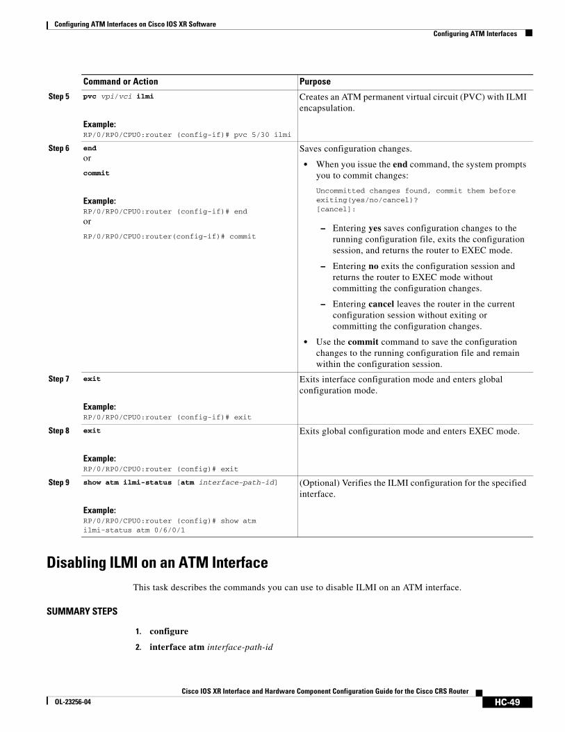
Configuring ATM Interfaces on Cisco IOS XR SoftwareConfiguring ATM Interfaces
Disabling ILMI on an ATM Interface This task describes the commands you can use to disable ILMI on an ATM interface.
SUMMARY STEPS
1. configure
2. interface atm interface-path-id
Step 5 pvc vpi/vci ilmi
Example:RP/0/RP0/CPU0:router (config-if)# pvc 5/30 ilmi
Creates an ATM permanent virtual circuit (PVC) with ILMI encapsulation.
Step 6 end
or
commit
Example:RP/0/RP0/CPU0:router (config-if)# end
or
RP/0/RP0/CPU0:router(config-if)# commit
Saves configuration changes.
• When you issue the end command, the system prompts you to commit changes:
Uncommitted changes found, commit them before exiting(yes/no/cancel)? [cancel]:
– Entering yes saves configuration changes to the running configuration file, exits the configuration session, and returns the router to EXEC mode.
– Entering no exits the configuration session and returns the router to EXEC mode without committing the configuration changes.
– Entering cancel leaves the router in the current configuration session without exiting or committing the configuration changes.
• Use the commit command to save the configuration changes to the running configuration file and remain within the configuration session.
Step 7 exit
Example:RP/0/RP0/CPU0:router (config-if)# exit
Exits interface configuration mode and enters global configuration mode.
Step 8 exit
Example:RP/0/RP0/CPU0:router (config)# exit
Exits global configuration mode and enters EXEC mode.
Step 9 show atm ilmi-status [atm interface-path-id]
Example:RP/0/RP0/CPU0:router (config)# show atm ilmi-status atm 0/6/0/1
(Optional) Verifies the ILMI configuration for the specified interface.
Command or Action Purpose
HC-49Cisco IOS XR Interface and Hardware Component Configuration Guide for the Cisco CRS Router
OL-23256-04

Configuring ATM Interfaces on Cisco IOS XR SoftwareConfiguring ATM Interfaces
3. atm ilmi-config disable
4. endorcommit
5. exit
6. exit
7. show atm ilmi-status [atm interface-path-id]
DETAILED STEPS
Command or Action Purpose
Step 1 configure
Example:RP/0/RP0/CPU0:router# configure
Enters global configuration mode.
Step 2 interface atm interface-path-id
Example:RP/0/RP0/CPU0:router (config)# interface atm 0/6/0/1
Enters ATM interface configuration mode.
Step 3 atm ilmi-config disable
Example:RP/0/RP0/CPU0:router (config-if)# atm ilmi-config disable
(Optional) Disables ILMI on the ATM interface.
To re-enable ILMI on an ATM interface, use the no atm ilmi-config disable form of this command.
Step 4 end
or
commit
Example:RP/0/RP0/CPU0:router (config-if)# end
or
RP/0/RP0/CPU0:router(config-if)# commit
Saves configuration changes.
• When you issue the end command, the system prompts you to commit changes:
Uncommitted changes found, commit them before exiting(yes/no/cancel)? [cancel]:
– Entering yes saves configuration changes to the running configuration file, exits the configuration session, and returns the router to EXEC mode.
– Entering no exits the configuration session and returns the router to EXEC mode without committing the configuration changes.
– Entering cancel leaves the router in the current configuration session without exiting or committing the configuration changes.
• Use the commit command to save the configuration changes to the running configuration file and remain within the configuration session.
HC-50Cisco IOS XR Interface and Hardware Component Configuration Guide for the Cisco CRS Router
OL-23256-04

Configuring ATM Interfaces on Cisco IOS XR SoftwareConfiguring ATM Interfaces
Step 5 exit
Example:RP/0/RP0/CPU0:router (config-if)# exit
Exits interface configuration mode and enters global configuration mode.
Step 6 exit
Example:RP/0/RP0/CPU0:router (config)# exit
Exits global configuration mode and enters EXEC mode.
Step 7 show atm ilmi-status [atm interface-path-id]
Example:RP/0/RP0/CPU0:router (config)# show atm ilmi-status atm 0/6/0/1
(Optional) Verifies the ILMI configuration for the specified interface.
Command or Action Purpose
HC-51Cisco IOS XR Interface and Hardware Component Configuration Guide for the Cisco CRS Router
OL-23256-04

Configuring ATM Interfaces on Cisco IOS XR SoftwareConfiguring ATM Interfaces
Attaching a Service-Policy to an Attachment CircuitThe QoS service-policy command can be configured for an attachment circuit in the following modes:
• PVC mode
• PVP mode
• Port mode
• Main Interface (non-port mode)
In PVC mode, PVP mode, and Port mode, the service policy is attached in the l2transport sub-interface mode. In non-port mode, the service policy is attached to the main interface.
Use the following procedures to attach a service-policy to an attachment circuit.
SUMMARY STEPS
PVC Mode
1. config
2. interface atm interface-path-id.subinterface l2transport
3. pvc vpi/vci
4. service-policy input | output policy_name
5. commit
PVP Mode
1. config
2. interface atm interface-path-id.subinterface l2transport
3. pvp vpi
4. service-policy input | output policy_name
5. commit
Port Mode
1. config
2. interface atm interface-path-id
3. l2transport
4. service-policy input | output policy_name
5. commit
Main Interface (non-port mode)
1. config
2. interface atm interface-path-id
3. service-policy input | output policy_name
4. commit
HC-52Cisco IOS XR Interface and Hardware Component Configuration Guide for the Cisco CRS Router
OL-23256-04

Configuring ATM Interfaces on Cisco IOS XR SoftwareConfiguring ATM Interfaces
DETAILED STEPS
Command or Action Purpose
PVC Mode
Step 1 config
Example:RP/0/RP0/CPU0:router# config terminal
Enters global configuration mode.
Step 2 interface atm interface-path-id.subinterface l2transport
Example:RP/0/RP0/CPU0:router(config)# interface atm 0/1/0/0.2 l2transport
Creates a subinterface and enters ATM subinterface configuration mode for that subinterface.
Step 3 interface atm interface-path-id
Example:RP/0/RP0/CPU0:router (config)# interface atm 0/1/0/1
Enters interface configuration mode for an ATM interface.
Step 4 service-policy input | output policy_name
Example:RP/0/RP0/CPU0(config-atm-l2transport-pvc)#service-policy input | output atm_policy_1
Attaches the specified service policy to the ATM PVC subinterface.
Step 5 commit
Example:RP/0/RP0/CPU0:router(config-if)# commit
Saves configuration changes.
PVP Mode
Step 1 config
Example:RP/0/RP0/CPU0:router# config terminal
Enters global configuration mode.
Step 2 interface atm interface-path-id.subinterface l2transport
Example:RP/0/RP0/CPU0:router(config)# interface atm 0/1/0/0.2 l2transport
Creates a subinterface and enters ATM subinterface configuration mode for that subinterface.
Step 3 pvp vpi
Example:RP/0/RP0/CPU0:router(config-subif)# pvp 30
(Optional) Creates an ATM PVP and enters ATM PVP configuration submode.
Note Only one PVP is allowed per subinterface.
HC-53Cisco IOS XR Interface and Hardware Component Configuration Guide for the Cisco CRS Router
OL-23256-04

Configuring ATM Interfaces on Cisco IOS XR SoftwareConfiguring ATM Interfaces
Step 4 service-policy input | output policy_name
Example:RP/0/RP0/CPU0(config-atm-l2transport-pvp)#service-policy input | output atm_policy_2
Attaches the specified service policy to the ATM PVP subinterface.
Step 5 commit
Example:RP/0/RP0/CPU0:router(config-if)# commit
Saves configuration changes.
Port Mode
Step 1 config
Example:RP/0/RP0/CPU0:router# config terminal
Enters global configuration mode.
Step 2 interface atm interface-path-id
Example:RP/0/RP0/CPU0:router (config)# interface atm 0/1/0/1
Enters interface configuration mode for an ATM interface.
Step 3 l2transport
Example:RP/0/RP0/CPU0:router (config-if)# l2transport
Enters ATM Layer 2 transport configuration mode, and enables Layer 2 port mode on this ATM interface.
Step 4 service-policy input | output policy_name
Example:RP/0/RP0/CPU0(config-if-l2)#service-policy input | output atm_policy_3
Attaches the specified service policy to the ATM Layer 2 subinterface.
Step 5 commit
Example:RP/0/RP0/CPU0:router(config-if)# commit
Saves configuration changes.
Main Interface (non-port mode)
Step 1 config
Example:RP/0/RP0/CPU0:router# config terminal
Enters global configuration mode.
Step 2 interface atm interface-path-id
Example:RP/0/RP0/CPU0:router (config)# interface atm 0/1/0/1
Enters interface configuration mode for an ATM interface.
Command or Action Purpose
HC-54Cisco IOS XR Interface and Hardware Component Configuration Guide for the Cisco CRS Router
OL-23256-04

Configuring ATM Interfaces on Cisco IOS XR SoftwareATM Configuration: Examples
ATM Configuration: ExamplesThis section provides the following configuration examples:
• ATM Interface Bring Up and Configuration: Example, page 55
• Point-To-Point ATM Subinterface Configuration: Example, page 55
• Layer 2 AC Creation and Configuration: Example, page 57
• VC-Class Creation and Configuration: Example, page 58
• ATM Layer 2 QoS Configuration: Examples, page 59
• Verifying ATM Layer 2 QoS Configuration: Examples, page 61
ATM Interface Bring Up and Configuration: ExampleThe following example shows how to bring up and configure an ATM interface:
RP/0/RP0/CPU0:router # configureRP/0/RP0/CPU0:router(config)# interface atm 0/6/0/0RP/0/RP0/CPU0:router(config-if)# atm address-registrationRP/0/RP0/CPU0:router(config-if)# no shutdownRP/0/RP0/CPU0:router(config-if)# commit
Point-To-Point ATM Subinterface Configuration: ExampleThe following example shows how to configure a point-to-point ATM subinterface on an ATM main interface:
RP/0/RP0/CPU0:router # configureRP/0/RP0/CPU0:router (config)# interface atm 0/2/0/2.1 point-to-pointRP/0/RP0/CPU0:router (config-if)# ipv4 address 10.46.8.6/24RP/0/RP0/CPU0:router (config-if)# pvc 0/200RP/0/RP0/CPU0:router (config-atm-vc)# commitRP/0/RP0/CPU0:router (config-atm-vc)# exitRP/0/RP0/CPU0:router (config-if)# exitRP/0/RP0/CPU0:router (config)# exit
RP/0/RP0/CPU0:router # show interfaces atm 0/2/0/2.1
ATM0/2/0/2.1 is up, line protocol is up Hardware is ATM network sub-interface(s)
Step 3 service-policy input | output policy_name
Example:RP/0/RP0/CPU0(config-if)#service-policy input | output atm_policy_4
Attaches the specified service policy to the main ATM interface.
Step 4 commit
Example:RP/0/RP0/CPU0:router(config-if)# commit
Saves configuration changes.
Command or Action Purpose
HC-55Cisco IOS XR Interface and Hardware Component Configuration Guide for the Cisco CRS Router
OL-23256-04

Configuring ATM Interfaces on Cisco IOS XR SoftwareATM Configuration: Examples
Description: Connect to P4_C12810 ATM 1/2.1 Internet address is 10.46.8.6/24 MTU 4470 bytes, BW 155000 Kbit reliability Unknown, txload Unknown, rxload Unknown Encapsulation AAL5/SNAP, controller loopback not set, Last clearing of "show interface" counters Unknown Datarate information unavailable. Interface counters unavailable.
RP/0/RP0/CPU0:router # show atm interface atm 0/2/0/3
Interface : ATM0/2/0/3AAL Enabled : AAL5 Max-VP : 254 Max-VC : 2046 Configured L2 PVPs : 0 Configured L2 PVCs : 0 Configured L3 VP-Tunnels : 0 Configured L3 PVCs : 1 L2 PVPs in Down State : 0 L2 PVCs in Down State : 0 L3 VP-Tunnels in Down State : 0 L3 PVCs in Down State : 0 Cell packing count : 0
Received Side Statistics: Received Cells : 0 Received Bytes : 0 Received AAL Packets : 0
Receive Side Cells Dropped: Unrecognized VPI/VCI : 0
Receive Side AAL5 Packets Dropped: Unavailable SAR Buffer : 0 Non-Resource Exhaustion : 0 Reassembly Timeout : 0 Zero Length : 0 Unavailable Host Buffer : 0 Packet size exceeds MPS : 0 AAL5 Trailer Length Errors : 0
Transmit Side Statistics: Transmitted Cells : 1899716067 Transmitted Bytes : 0 Transmitted AAL Packets : 0
Transmit Side Cells Dropped: Unrecognized VPI/VCI : 0
Transmit Side AAL5 Packets Dropped: Unavailable SAR Buffer : 0 Non-Resource Exhaustion : 0 WRED Threshold : 0 WRED Random : 0
RP/0/RP0/CPU0:router # show atm pvc 10/100
Detailed display of VC(s) with VPI/VCI = 10/100
ATM0/2/0/3.100: VPI: 10 VCI: 100UBR, PeakRate: 622000 KbpsAAL5-LLC/SNAPOAM frequency: 10 second(s), OAM retry frequency: 1 second(s),
HC-56Cisco IOS XR Interface and Hardware Component Configuration Guide for the Cisco CRS Router
OL-23256-04

Configuring ATM Interfaces on Cisco IOS XR SoftwareATM Configuration: Examples
OAM up retry count: 3, OAM down retry count: 5,OAM Keep-vc-up: False, OAM AIS-RDI failure: None,OAM AIS-RDI down count: 1, OAM AIS-RDI up time: 3 second(s),OAM Loopback status: No loopback enabled,OAM VC state: Loopback Not verified,VC is not managed by OAM,
OAM cells received: 0,F5 InEndLoop: 0, F5 InSegLoop: 0,F5 InEndAIS: 0, F5 InSegAIS: 0,F5 InEndRDI: 0, F5 InSegRDI: 0,OAM cells sent: 0,F5 OutEndLoop: 0, F5 OutSegLoop: 0,F5 OutEndAIS: 0, F5 OutSegAIS: 0,F5 OutEndRDI: 0, F5 OutSegRDI: 0,OAM cells drops: 0
InPkts: 0 OutPkts: 0 InBytes: 0 OutBytes: 0 WRED pkt drop: 0 Non WRED pkt drop: 0
Internal state: READYStatus: UP
Layer 2 AC Creation and Configuration: ExampleThe following example shows how to create and configure one endpoint of a Layer 2 port mode AC:
RP/0/RP0/CPU0:router# configureRP/0/RP0/CPU0:router (config)# interface atm 0/6/0/1RP/0/RP0/CPU0:router (config-if)# l2transportRP/0/RP0/CPU0:router (config-if-l2)# cell-packing 6 1 RP/0/RP0/CPU0:router(config-if-l2)# commit
The following example shows how to create and configure an AC on a Layer 2 subinterface with a PVC:
RP/0/RP0/CPU0:router# configureRP/0/RP0/CPU0:router(config)# interface atm 0/1/0/0.230 l2transportRP/0/RP0/CPU0:router(config-if)# pvc 15/230RP/0/RP0/CPU0:router(config-atm-l2transport-pvc)# encapsulation aal0RP/0/RP0/CPU0:router(config-atm-l2transport-pvc)# cell-packing 5 2RP/0/RP0/CPU0:router(config-atm-l2transport-pvc)# shape cbr 622000RP/0/RP0/CPU0:router(config-atm-l2transport-pvc)# commitRP/0/RP0/CPU0:router(config-atm-l2transport-pvc)# RP/0/RP0/CPU0:router(config-if)# exitRP/0/RP0/CPU0:router(config)# exitRP/0/RP0/CPU0:router# show atm pvc
Peak Avg/Min BurstInterface VPI VCI Type Encaps SC Kbps Kbps Cells StsATM0/1/0/0.230 15 230 PVC AAL0 UBR 622000 N/A N/A UPATM0/1/0/3.19 17 19 PVC SNAP UBR 622000 N/A N/A UP
HC-57Cisco IOS XR Interface and Hardware Component Configuration Guide for the Cisco CRS Router
OL-23256-04

Configuring ATM Interfaces on Cisco IOS XR SoftwareATM Configuration: Examples
The following example shows how to create and configure an AC on an ATM subinterface with a PVP:
RP/0/RP0/CPU0:router# configureRP/0/RP0/CPU0:router(config)# interface atm 0/6/0/1.10 l2transportRP/0/RP0/CPU0:router(config-if)# pvp 100RP/0/RP0/CPU0:router(config-atm-l2transport-pvp)# cell-packing 5 2RP/0/RP0/CPU0:router(config-atm-l2transport-pvp)# shape ubr 155000RP/0/RP0/CPU0:router(config-atm-l2transport-pvp)# commit
RP/0/RP0/CPU0:router# show atm pvp interface atm 0/6/0/1
Peak Avg/Min BurstInterface VPI SC Kbps Kbps Cells StsATM0/6/0/1.10 100 UBR 155000 N/A N/A UP
VC-Class Creation and Configuration: ExampleThe following example shows how to configure a vc-class:
RP/0/RP0/CPU0:router # configureRP/0/RP0/CPU0:router(config)# vc-class atm atm-class-1RP/0/RP0/CPU0:router(config-vc-class-atm)# encapsulation aal5snapRP/0/RP0/CPU0:router(config-vc-class-atm)# oam ais-rdi 25 5 RP/0/RP0/CPU0:router(config-vc-class-atm)# oam retry 5 10 5 RP/0/RP0/CPU0:router(config-vc-class-atm)# oam-pvc manage 300 RP/0/RP0/CPU0:router(config-vc-class-atm)# shape cbr 100000RP/0/RP0/CPU0:router(config-vc-class-atm)# commit
The following example shows how to attach a vc-class to an ATM main interface:
RP/0/RP0/CPU0:router # configureRP/0/RP0/CPU0:router(config)# interface ATM0/2/0/0.1 point-to-pointRP/0/RP0/CPU0:router (config-if)# class-int atm-class-1RP/0/RP0/CPU0:router (config-if)# commit
The following example shows how to attach a vc-class to an ATM subinterface:
RP/0/RP0/CPU0:router # configureRP/0/RP0/CPU0:router(config)# interface ATM0/2/0/0.1 point-to-pointRP/0/RP0/CPU0:router(config-if)# pvc 10/100RP/0/RP0/CPU0:router (config-atm-vc)# class-vc atm-class-1RP/0/RP0/CPU0:router (config-atm-vc)# commit
The following example shows how to display information about a specific ATM vc-class:
RP/0/RP0/CPU0:router # show atm vc-class atm-class-1ATM vc-class atm-class-1
encapsulation - aal5snap shape - cbr 100000 oam ais-rdi - not configured oam retry - not configured oam-pvc - manage 300
The following example shows how to display configuration information for the parameters on a virtual circuit (VC) class that is associated with a particular PVC:
RP/0/RP0/CPU0:router # show atm class-link 10/100
Detailed display of VC(s) with VPI/VCI = 10/100
Class link for VC 10/100ATM0/2/0/0.1: VPI: 10 VCI: 100
HC-58Cisco IOS XR Interface and Hardware Component Configuration Guide for the Cisco CRS Router
OL-23256-04

Configuring ATM Interfaces on Cisco IOS XR SoftwareATM Configuration: Examples
shape : cbr 100000 (VC-class configured on VC)encapsulation : aal5snap (VC-class configured on VC)oam-pvc : manage 300 (VC-class configured on VC)oam retry : 3 5 1 (Default value)oam ais-rdi : 1 3 (Default value)
ATM Layer 2 QoS Configuration: Examples The following examples show how to configure QoS for ATM. For complete information on configuring QoS and QoS commands, refer to the Cisco XR 12000 Series Router Modular Quality of Service Configuration Guide and the Cisco XR 12000 Series Router Modular Quality of Service Command Reference.
Attaching a Service-Policy to an Attachment Circuit Configuration: Example
PVC Modeconfig interface ATM 0/1/0/0.2 l2transport pvc 10/2 service-policy input | output atm_policy_o
PVP Modeconfig interface ATM 0/1/0/0.3 l2transport pvp 30 service-policy input atm_policy_i
Port Modeconfig interface ATM 0/1/0/0 l2transport service-policy input atm_policy_i
Main Interface (non-port mode)config interface ATM 0/1/0/0 service-policy input | output atm_policy_o
Policy Map Configuration for CBR/UBR: Example
For CBR.1 (real-time traffic) and UBR (best effort, non-real time traffic) you must specify the PCR and delay tolerance parameters for policing. The main difference between the configurations for UBR.1 and UBR.2 traffic is that for UBR.2 traffic, the exceed action includes the set-clp-transmit option to tag non-conforming cells. The police rate can also be expressed as a percentage.
The following example shows how to configure a QoS policy map for CBR/UBR:
policy-map CBR1 class class-default police rate pcr cellsps delay-tolerance cdvt us conform-action action exceed-action action
HC-59Cisco IOS XR Interface and Hardware Component Configuration Guide for the Cisco CRS Router
OL-23256-04

Configuring ATM Interfaces on Cisco IOS XR SoftwareATM Configuration: Examples
Policy Map Configuration for VBR.1: Example
For VBR.1 real-time and non-real time traffic you must specify the PCR, SCR, and delay tolerance parameters for for policing. The atm-mbs parameter can be specified to define the burst allowed on the SCR bucket. The police rates can also be expressed as percentages. Class atm_clp1 is allowed with police actions.
The following example shows how to configure a QoS policy map for VBR.1:
policy-map VBR1 class class-default police rate scr cellsps atm-mbs mbs cells peak-rate pcr cellsps delay-tolerance cdvt us conform-action action exceed-action action
Policy Map Configuration for VBR.2 and VBR.3: Example
For VBR.2 and VBR.3 real-time and non-real time traffic you must specify the PCR, SCR, and delay tolerance parameters for policing. The atm-mbs parameter can be specified to define the burst allowed on the SCR bucket. The main difference between VBR.1 and VBR.2/VBR.3 is that the SCR bucket is for CLP0 cells only. The police rates can be expressed as percentages. The child policy can have other set actions and can match on ATM CLP1.
The following example shows how to configure a hierarchical policy for VBR.2:
policy-map child class atm_clp0 police rate scr cellsps atm-mbs mbs cells conform-action action exceed-action action
policy-map VBR2 class class-default police rate pcr cellsps delay-tolerance cdvt us conform-action action exceed-action action service-policy child
Policy Map Configuration to Exclude OAM Cells: Example
OAM cells can be excluded from being policed by configuring the classification criteria. Since match not is not supported, the different classes must be explicitly configured:.
The following example shows how to configure a policy map to exclude OAM cells:
class-map clp-0-1 match clp 0 match clp 1
policy-map child class atm-oam set class class-default police rate scr cellsps atm-mbs mbs cells conform-action action exceed-action action
policy-map VBR2 class clp-0-1
HC-60Cisco IOS XR Interface and Hardware Component Configuration Guide for the Cisco CRS Router
OL-23256-04

Configuring ATM Interfaces on Cisco IOS XR SoftwareATM Configuration: Examples
police rate pcr cellsps delay-tolerance cdvt us conform-action action exceed-action action service-policy child
Policy Map Configuration for Dual Queue Limit: Example
Dual Queue limit configuration is supported on egress L2 ATM interfaces to differentiate between CLP0 and CLP1 cells.
Note For dual queue, only output service policies are supported. Input service policies are not supported.
The following example shows how to configure a policy map for Dual Queue Limit:
policy-map q-limit class class-default queue-limit atm-clp Threshold {[ms|us|cells]} Tail-drop-threshold {[ms|us|cells]}
Verifying ATM Layer 2 QoS Configuration: Examples The following examples show how to display policing results for an ATM interface policy map:
show policy-map interface ATM 0/3/0/0.12 input
ATM 0/3/0/0.12 input: pvc1
Class class-default Classification statistics (packets/bytes) (rate - kbps) Matched : 0/0 0 Transmitted : 0/0 0 Total Dropped : 0/0 0
show policy-map interface ATM 0/3/0/0.12 output
ATM 0/3/0/0.12 output: pvc1
Class class-default Classification statistics (packets/bytes) (rate - kbps) Matched : 0/0 0 Transmitted : 0/0 0 Total Dropped : 0/0 0
The following examples show how to display the configured QoS properties for an ATM interface policy map:
show qos interface atm 0/3/0/0.12 input
Interface ATM0_3_0_0.12 -- Direction: inputPolicy : pvc1Total number of classes: 1Cell Packing Criteria = CELL_PACK_TIMER_MTU---------------------------------------------------LEVEL1 class: classid = 0x1class name = class-defaultnew exp = 6
show qos interface atm 0/3/0/0.12 output
HC-61Cisco IOS XR Interface and Hardware Component Configuration Guide for the Cisco CRS Router
OL-23256-04

Configuring ATM Interfaces on Cisco IOS XR SoftwareATM Configuration: Examples
Interface ATM0_3_0_0.12 -- Direction: outputPolicy : pvc1Total number of classes: 1Cell Packing Criteria = CELL_PACK_TIMER_MTU---------------------------------------------------LEVEL1 class: classid = 0x1class name = class-defaultnew exp = 6
HC-62Cisco IOS XR Interface and Hardware Component Configuration Guide for the Cisco CRS Router
OL-23256-04

Configuring ATM Interfaces on Cisco IOS XR SoftwareAdditional References
Additional ReferencesThe following sections provide references related to implementing ATM for Cisco IOS XR software.
Related Documents
Standards
MIBs
RFCs
Related Topic Document Title
ATM commands: complete command syntax, command modes, command history, defaults, usage guidelines, and examples
Cisco IOS XR Interface and Hardware Command Reference
Standards Title
No new or modified standards are supported by this feature, and support for existing standards has not been modified by this feature.
—
MIBs MIBs Link
— To locate and download MIBs using Cisco IOS XR software, use the Cisco MIB Locator found at the following URL and choose a platform under the Cisco Access Products menu: http://cisco.com/public/sw-center/netmgmt/cmtk/mibs.shtml
RFCs Title
RFC 1483 Multiprotocol Encapsulation over ATM Adaptation Layer 5
RFC 1577 Classical IP and ARP over ATM.
RFC 2225 Classical IP and ARP over ATM
RFC 2255 The LDAP URL Format
RFC 2684 Multiprotocol Encapsulation over ATM Adaptation Layer 5.
RFC 4385 Pseudowire Emulation Edge-to-Edge (PWE3) Control Word for Use over an MPLS PSN
RFC 4717 Encapsulation Methods for Transport of Asynchronous Transfer Mode (ATM) over MPLS Networks
RFC 4816 Pseudowire Emulation Edge-to-Edge (PWE3) Asynchronous Transfer Mode (ATM) Transparent Cell Transport Service
HC-63Cisco IOS XR Interface and Hardware Component Configuration Guide for the Cisco CRS Router
OL-23256-04

Configuring ATM Interfaces on Cisco IOS XR SoftwareAdditional References
Technical Assistance
Description Link
The Cisco Technical Support website contains thousands of pages of searchable technical content, including links to products, technologies, solutions, technical tips, and tools. Registered Cisco.com users can log in from this page to access even more content.
http://www.cisco.com/techsupport
HC-64Cisco IOS XR Interface and Hardware Component Configuration Guide for the Cisco CRS Router
OL-23256-04