Embed Size (px)
Citation preview
HUAWEI CX600 Metro Services PlatformV600R003C00
Configuration Guide - MPLS
Issue 01
Date 2011-05-30
HUAWEI TECHNOLOGIES CO., LTD.

Copyright © Huawei Technologies Co., Ltd. 2011. All rights reserved.No part of this document may be reproduced or transmitted in any form or by any means without prior writtenconsent of Huawei Technologies Co., Ltd. Trademarks and Permissions
and other Huawei trademarks are trademarks of Huawei Technologies Co., Ltd.All other trademarks and trade names mentioned in this document are the property of their respective holders. NoticeThe purchased products, services and features are stipulated by the contract made between Huawei and thecustomer. All or part of the products, services and features described in this document may not be within thepurchase scope or the usage scope. Unless otherwise specified in the contract, all statements, information,and recommendations in this document are provided "AS IS" without warranties, guarantees or representationsof any kind, either express or implied.
The information in this document is subject to change without notice. Every effort has been made in thepreparation of this document to ensure accuracy of the contents, but all statements, information, andrecommendations in this document do not constitute the warranty of any kind, express or implied.
Huawei Technologies Co., Ltd.Address: Huawei Industrial Base
Bantian, LonggangShenzhen 518129People's Republic of China
Website: http://www.huawei.com
Email: [email protected]
Issue 01 (2011-05-30) Huawei Proprietary and ConfidentialCopyright © Huawei Technologies Co., Ltd.
i

About This Document
PurposeThis document describes related MPLS configurations supported by the CX600, including thebasic principle and configuration procedures of static LSPs, MPLS LDP, MPLS TE, MPLSfeatures, and MPLS OAM, and provides related configuration examples. The appendixes listcommon glossary, and acronyms and abbreviations of MPLS.
NOTE
l This document takes interface numbers and link types of the CX600-X8 as an example. In workingsituations, the actual interface numbers and link types may be different from those used in thisdocument.
l On CX600 series excluding CX600-X1 and CX600-X2, line processing boards are called LineProcessing Units (LPUs) and switching fabric boards are called Switching Fabric Units (SFUs). Onthe CX600-X1 and CX600-X2, there are no LPUs and SFUs, and NPUs implement the same functionsof LPUs and SFUs to exchange and forward packets.
Intended AudienceThe intended audience of this document is:
l Commissioning Engineerl Data Configuration Engineerl Network Monitoring Engineerl System Maintenance Engineer
Symbol ConventionsThe symbols that may be found in this document are defined as follows.
Symbol Description
DANGERAlerts you to a high risk hazard that could, if not avoided,result in serious injury or death.
WARNINGAlerts you to a medium or low risk hazard that could, ifnot avoided, result in moderate or minor injury.
HUAWEI CX600 Metro Services PlatformConfiguration Guide - MPLS About This Document
Issue 01 (2011-05-30) Huawei Proprietary and ConfidentialCopyright © Huawei Technologies Co., Ltd.
iii
Symbol Description
CAUTIONAlerts you to a potentially hazardous situation that could,if not avoided, result in equipment damage, data loss,performance deterioration, or unanticipated results.
TIP Provides a tip that may help you solve a problem or savetime.
NOTE Provides additional information to emphasize orsupplement important points in the main text.
Change HistoryChanges between document issues are cumulative. The latest document issue contains all thechanges made in earlier issues.
Changes in Issue 01 (2011-05-30)Initial commercial release.
About This DocumentHUAWEI CX600 Metro Services Platform
Configuration Guide - MPLS
iv Huawei Proprietary and ConfidentialCopyright © Huawei Technologies Co., Ltd.
Issue 01 (2011-05-30)
Contents
About This Document...................................................................................................................iii
1 Static LSPs Configuration........................................................................................................1-11.1 Introduction to Static LSPs.............................................................................................................................1-2
1.1.1 Overview of Static LSPs........................................................................................................................1-21.1.2 Static LSPs Features Supported by the CX600......................................................................................1-2
1.2 Configuring Static LSPs..................................................................................................................................1-21.2.1 Establishing the Configuration Task......................................................................................................1-31.2.2 Configuring the LSR ID.........................................................................................................................1-41.2.3 Enabling MPLS......................................................................................................................................1-41.2.4 Configuring the Ingress for a Static LSP...............................................................................................1-51.2.5 Configuring the Transit for a Static LSP................................................................................................1-61.2.6 Configuring the Egress for a Static LSP................................................................................................1-61.2.7 Checking the Configuration...................................................................................................................1-6
1.3 Configuring Static BFD for Static LSP...........................................................................................................1-71.3.1 Establishing the Configuration Task......................................................................................................1-81.3.2 Enable Global BFD Capability..............................................................................................................1-91.3.3 Configuring BFD with Specific Parameters on Ingress.........................................................................1-91.3.4 Configuring BFD with Specific Parameters on Egress........................................................................1-111.3.5 Checking the Configuration.................................................................................................................1-13
1.4 Maintaining Static LSPs................................................................................................................................1-131.4.1 Clearing MPLS Statistics.....................................................................................................................1-141.4.2 Checking the LSP Connectivity and Reachability...............................................................................1-141.4.3 Enabling the Trap Function of LSP......................................................................................................1-15
1.5 Configuration Examples................................................................................................................................1-151.5.1 Example for Configuring Static LSPs..................................................................................................1-151.5.2 Example for Configuring Static BFD for Static LSP...........................................................................1-22
2 MPLS LDP Configuration........................................................................................................2-12.1 Introduction to MPLS LDP.............................................................................................................................2-3
2.1.1 MPLS LDP Overview............................................................................................................................2-32.1.2 MPLS LDP Features Supported by the CX600.....................................................................................2-3
2.2 Configuring LDP Sessions..............................................................................................................................2-52.2.1 Establishing the Configuration Task......................................................................................................2-6
HUAWEI CX600 Metro Services PlatformConfiguration Guide - MPLS Contents
Issue 01 (2011-05-30) Huawei Proprietary and ConfidentialCopyright © Huawei Technologies Co., Ltd.
v
2.2.2 Configuring the LSR ID.........................................................................................................................2-82.2.3 Enabling MPLS......................................................................................................................................2-82.2.4 Enable Global MPLS LDP.....................................................................................................................2-92.2.5 (Optional) Configuring the LDP Dynamic Capability Announcement Function................................2-102.2.6 Configuring LDP Sessions...................................................................................................................2-112.2.7 (Optional) Configuring LDP Transport Addresses..............................................................................2-122.2.8 (Optional) Configuring LDP Timers....................................................................................................2-132.2.9 (Optional) Configuring LDP MD5 Authentication..............................................................................2-172.2.10 (Optional) Configuring LDP Authentication.....................................................................................2-182.2.11 Checking the Configuration...............................................................................................................2-20
2.3 Configuring LDP LSP...................................................................................................................................2-232.3.1 Establishing the Configuration Task....................................................................................................2-242.3.2 Configuring LDP LSP..........................................................................................................................2-252.3.3 (Optional) Configuring Label Advertisement Modes..........................................................................2-252.3.4 (Optional) Configuring LDP to Automatically Trigger the Request in DoD Mode............................2-262.3.5 (Optional) Configuring Loop Detection...............................................................................................2-272.3.6 (Optional) Configuring LDP MTU Signaling......................................................................................2-282.3.7 (Optional) Configuring split horizon....................................................................................................2-282.3.8 (Optional) Configuring an Inbound LDP Policy..................................................................................2-292.3.9 (Optional) Configuring an Outbound LDP Policy...............................................................................2-302.3.10 (Optional) Configuring the Policy of Triggering to Establish LSPs..................................................2-322.3.11 (Optional) Configuring the Policy of Establishing Transit LSPs.......................................................2-332.3.12 Checking the Configuration...............................................................................................................2-33
2.4 Configuring LDP Extension for Inter-Area LSP...........................................................................................2-342.4.1 Establishing the Configuration Task....................................................................................................2-352.4.2 Configuring LDP Extension for Inter-Area LSP..................................................................................2-352.4.3 Checking the Configuration.................................................................................................................2-36
2.5 Configuring the LDP Multi-Instance............................................................................................................2-362.5.1 Establishing the Configuration Task....................................................................................................2-372.5.2 Configuring the LDP Multi-Instance...................................................................................................2-372.5.3 Checking the Configuration.................................................................................................................2-38
2.6 Configuring Static BFD for LDP LSP..........................................................................................................2-392.6.1 Establishing the Configuration Task....................................................................................................2-392.6.2 Enabling Global BFD Capability.........................................................................................................2-402.6.3 Configuring BFD with Specific Parameters on Ingress.......................................................................2-402.6.4 Configuring BFD with Specific Parameters on Egress........................................................................2-422.6.5 Checking the Configuration.................................................................................................................2-44
2.7 Configuring Dynamic BFD for LDP LSP.....................................................................................................2-452.7.1 Establishing the Configuration Task....................................................................................................2-452.7.2 Enabling Global BFD Capability.........................................................................................................2-462.7.3 Enabling MPLS to Establish BFD Session Dynamically.....................................................................2-462.7.4 Configuring the Triggering Policy of Dynamic BFD for LDP LSP....................................................2-47
ContentsHUAWEI CX600 Metro Services Platform
Configuration Guide - MPLS
vi Huawei Proprietary and ConfidentialCopyright © Huawei Technologies Co., Ltd.
Issue 01 (2011-05-30)
2.7.5 (Optional) Adjusting BFD Parameters.................................................................................................2-482.7.6 Checking the Configuration.................................................................................................................2-49
2.8 Configuring Manual LDP FRR.....................................................................................................................2-512.8.1 Establishing the Configuration Task....................................................................................................2-512.8.2 Enabling Manual LDP FRR.................................................................................................................2-522.8.3 (Optional) Configuring Manual LDP FRR Protection Timer..............................................................2-532.8.4 (Optional) Allowing BFD to Modify the PST.....................................................................................2-532.8.5 Checking the Configuration.................................................................................................................2-54
2.9 Configuring LDP Auto FRR.........................................................................................................................2-542.9.1 Establishing the Configuration Task....................................................................................................2-552.9.2 Enabling LDP Auto FRR.....................................................................................................................2-552.9.3 Checking the Configuration.................................................................................................................2-56
2.10 Configuring Synchronization Between LDP and IGP................................................................................2-572.10.1 Establishing the Configuration Task..................................................................................................2-572.10.2 Enabling Synchronization Between LDP and IGP............................................................................2-582.10.3 (Optional) Setting the Hold-down Timer Value................................................................................2-592.10.4 (Optional) Setting the Hold-max-cost Timer Value...........................................................................2-602.10.5 (Optional) Setting the Delay Timer Value.........................................................................................2-612.10.6 Checking the Configuration...............................................................................................................2-61
2.11 Configuring Synchronization Between LDP and Static Routes..................................................................2-622.11.1 Establishing the Configuration Task..................................................................................................2-622.11.2 Enabling Synchronization Between LDP and Static Routes..............................................................2-642.11.3 (Optional) Setting a Hold-down Timer..............................................................................................2-652.11.4 Checking the Configuration...............................................................................................................2-66
2.12 Configuring LDP GTSM.............................................................................................................................2-662.12.1 Establishing the Configuration Task..................................................................................................2-672.12.2 Configuring LDP GTSM....................................................................................................................2-672.12.3 Checking the Configuration...............................................................................................................2-68
2.13 Configuring LDP GR..................................................................................................................................2-682.13.1 Establishing the Configuration Task..................................................................................................2-692.13.2 Enabling LDP GR..............................................................................................................................2-702.13.3 (Optional) Configuring GR Restarter Timer......................................................................................2-702.13.4 (Optional) Configuring the timer of GR Helper.................................................................................2-712.13.5 Checking the Configuration...............................................................................................................2-72
2.14 Maintaining MPLS LDP.............................................................................................................................2-722.14.1 Resetting LDP....................................................................................................................................2-732.14.2 Clearing MPLS Statistics...................................................................................................................2-732.14.3 Checking the LSP Connectivity and Reachability.............................................................................2-742.14.4 Enabling the Trap Function of LSP....................................................................................................2-74
2.15 Configuration Examples..............................................................................................................................2-742.15.1 Example for Configuring Local LDP Sessions..................................................................................2-762.15.2 Example for Configuring Remote MPLS LDP Sessions...................................................................2-79
HUAWEI CX600 Metro Services PlatformConfiguration Guide - MPLS Contents
Issue 01 (2011-05-30) Huawei Proprietary and ConfidentialCopyright © Huawei Technologies Co., Ltd.
vii
2.15.3 Example for Configuring LSPs by Using LDP..................................................................................2-832.15.4 Example for Configuring LDP to Automatically Trigger a Request in DoD Mode..........................2-862.15.5 Example for Configuring an Inbound LDP Policy.............................................................................2-932.15.6 Example for Configuring an Outbound LDP Policy..........................................................................2-982.15.7 Example for Configuring Transit LSPs Through the Prefix List.....................................................2-1032.15.8 Example for Configuring LDP Extension for Inter-Area LSP.........................................................2-1082.15.9 Example for Configuring Static BFD for LDP LSP........................................................................2-1152.15.10 Example for Configuring Dynamic BFD for LDP LSP.................................................................2-1212.15.11 Example for Configuring Manual LDP FRR.................................................................................2-1252.15.12 Example for Configuring LDP Auto FRR.....................................................................................2-1312.15.13 Example for Configuring Synchronization Between LDP and IGP...............................................2-1402.15.14 Example for Configuring Synchronization Between LDP and Static Routes................................2-1472.15.15 Example for Configuring LDP GTSM...........................................................................................2-1522.15.16 Example for Configuring LDP GR................................................................................................2-155
3 MPLS TE Configuration...........................................................................................................3-13.1 Introduction to MPLS TE................................................................................................................................3-4
3.1.1 MPLS TE Overview...............................................................................................................................3-43.1.2 MPLS TE Features Supported by the CX600........................................................................................3-4
3.2 Configuring Static CR-LSP.............................................................................................................................3-73.2.1 Establishing the Configuration Task......................................................................................................3-73.2.2 Enabling MPLS TE................................................................................................................................3-83.2.3 (Optional) Configuring Link Bandwidth................................................................................................3-93.2.4 Configuring the MPLS TE Tunnel Interface........................................................................................3-103.2.5 Configuring the Ingress of the Static CR-LSP.....................................................................................3-113.2.6 Configuring the Transit of the Static CR-LSP.....................................................................................3-123.2.7 Configuring the Egress of the Static CR-LSP......................................................................................3-133.2.8 Checking the Configuration.................................................................................................................3-13
3.3 Configuring a Static Bidirectional Co-routed LSP.......................................................................................3-143.3.1 Establishing the Configuration Task....................................................................................................3-143.3.2 Enabling MPLS TE..............................................................................................................................3-153.3.3 (Optional) Configuring Link Bandwidth..............................................................................................3-163.3.4 Configuring a Tunnel Interface on the Ingress.....................................................................................3-173.3.5 Configure the Ingress of a Static Bidirectional Co-routed LSP...........................................................3-183.3.6 Configure a Transit Node of a Static Bidirectional Co-routed LSP.....................................................3-193.3.7 Configure the Egress of a Static Bidirectional Co-routed LSP............................................................3-203.3.8 Configuring the Tunnel Interface on the Egress..................................................................................3-213.3.9 Checking the Configuration.................................................................................................................3-21
3.4 Configuring an RSVP-TE Tunnel.................................................................................................................3-223.4.1 Establishing the Configuration Task....................................................................................................3-233.4.2 Enabling MPLS TE and RSVP-TE......................................................................................................3-233.4.3 (Optional) Configuring Link Bandwidth..............................................................................................3-243.4.4 Configuring OSPF TE..........................................................................................................................3-25
ContentsHUAWEI CX600 Metro Services Platform
Configuration Guide - MPLS
viii Huawei Proprietary and ConfidentialCopyright © Huawei Technologies Co., Ltd.
Issue 01 (2011-05-30)
3.4.5 Configuring IS-IS TE...........................................................................................................................3-263.4.6 (Optional) Configuring an MPLS TE Explicit Path.............................................................................3-273.4.7 Configuring the MPLS TE Tunnel Interface........................................................................................3-283.4.8 Configuring Constraints for an MPLS TE Tunnel...............................................................................3-303.4.9 (Optional) Configuring RSVP Resource Reservation Style................................................................3-313.4.10 Configuring CSPF..............................................................................................................................3-313.4.11 Checking the Configuration...............................................................................................................3-32
3.5 Referencing the CR-LSP Attribute Template to Set Up a CR-LSP..............................................................3-343.5.1 Establishing the Configuration Task....................................................................................................3-343.5.2 Configuring a CR-LSP Attribute Template.........................................................................................3-353.5.3 Setting Up a CR-LSP by Using a CR-LSP Attribute Template...........................................................3-373.5.4 Checking the Configuration.................................................................................................................3-39
3.6 Adjusting RSVP Signaling Parameters.........................................................................................................3-393.6.1 Establishing the Configuration Task....................................................................................................3-403.6.2 Configuring RSVP Hello Extension....................................................................................................3-413.6.3 Configuring RSVP Timers...................................................................................................................3-423.6.4 Configuring RSVP Refresh Mechanism..............................................................................................3-433.6.5 Enabling Reservation Confirmation Mechanism.................................................................................3-443.6.6 Checking the Configuration.................................................................................................................3-44
3.7 Configuring RSVP Authentication................................................................................................................3-453.7.1 Establishing the Configuration Task....................................................................................................3-453.7.2 Configuring RSVP Key Authentication...............................................................................................3-463.7.3 (Optional) Configuring the RSVP Authentication Lifetime................................................................3-483.7.4 (Optional) Configuring the Handshake Function.................................................................................3-493.7.5 (Optional) Configuring the Message Window Function......................................................................3-503.7.6 Checking the Configuration.................................................................................................................3-51
3.8 Adjusting the Path of CR-LSP......................................................................................................................3-513.8.1 Establishing the Configuration Task....................................................................................................3-523.8.2 Configuring Administrative Group and Affinity Property...................................................................3-543.8.3 Configuring SRLG...............................................................................................................................3-553.8.4 Configuring CR-LSP Hop Limit..........................................................................................................3-563.8.5 Configuring Metrics for Path Calculation............................................................................................3-563.8.6 Configuring Tie-Breaking of CSPF.....................................................................................................3-573.8.7 Configuring Failed Link Timer............................................................................................................3-583.8.8 Configuring Loop Detection................................................................................................................3-593.8.9 Configuring Route Pinning..................................................................................................................3-603.8.10 Checking the Configuration...............................................................................................................3-61
3.9 Adjusting the Establishment of MPLS TE Tunnels......................................................................................3-613.9.1 Establishing the Configuration Task....................................................................................................3-623.9.2 Configuring the Tunnel Priority...........................................................................................................3-633.9.3 Configuring Re-optimization for CR-LSP...........................................................................................3-633.9.4 Configuring Tunnel Reestablishment Parameters................................................................................3-64
HUAWEI CX600 Metro Services PlatformConfiguration Guide - MPLS Contents
Issue 01 (2011-05-30) Huawei Proprietary and ConfidentialCopyright © Huawei Technologies Co., Ltd.
ix
3.9.5 Configuring Route Record and Label Record......................................................................................3-653.9.6 Configuring the RSVP Signaling Delay-Trigger Function..................................................................3-663.9.7 Checking the Configuration.................................................................................................................3-66
3.10 Adjusting the Traffic Forwarding of an MPLS TE Tunnel.........................................................................3-673.10.1 Establishing the Configuration Task..................................................................................................3-673.10.2 Configuring IGP Shortcut..................................................................................................................3-683.10.3 Configuring Forwarding Adjacency...................................................................................................3-693.10.4 Configuring Switching Delay and Deletion Delay............................................................................3-70
3.11 Adjusting Flooding Threshold of Bandwidth Change................................................................................3-713.11.1 Establishing the Configuration Task..................................................................................................3-713.11.2 Configuring Flooding Threshold........................................................................................................3-72
3.12 Configuring Automatic Adjustment of the Tunnel Bandwidth...................................................................3-733.12.1 Establishing the Configuration Task..................................................................................................3-733.12.2 Configuring Auto Bandwidth Adjustment.........................................................................................3-743.12.3 Checking the Configuration...............................................................................................................3-76
3.13 Configuring the Limit Rate of MPLS TE Traffic.......................................................................................3-763.13.1 Establishing the Configuration Task..................................................................................................3-763.13.2 Configuring the Limit Rate of MPLS TE Traffic..............................................................................3-773.13.3 Checking the Configuration...............................................................................................................3-78
3.14 Configuring DS-TE Tunnel.........................................................................................................................3-783.14.1 Establishing the Configuration Task..................................................................................................3-793.14.2 Configuring DS-TE Mode..................................................................................................................3-803.14.3 Configuring DS-TE Bandwidth Constraints Model...........................................................................3-823.14.4 (Optional) Configuring TE-Class Mapping Table.............................................................................3-823.14.5 Configuring Link Bandwidth.............................................................................................................3-843.14.6 Configuring the Tunnel Interface.......................................................................................................3-853.14.7 Configuring the Static CR-LSP and the Bandwidth...........................................................................3-873.14.8 Configuring the RSVP CR-LSP and Its Bandwidth...........................................................................3-883.14.9 Configuring Mappings Between CTs and Flow Queues....................................................................3-903.14.10 (Optional) Configuring the Interface Class Queue...........................................................................3-923.14.11 Checking the Configuration.............................................................................................................3-93
3.15 Configuring MPLS TE FRR.......................................................................................................................3-943.15.1 Establishing the Configuration Task..................................................................................................3-943.15.2 Enabling TE Fast Reroute..................................................................................................................3-963.15.3 Configuring Bypass Tunnels..............................................................................................................3-963.15.4 (Optional) Configuring the Scanning Timer for FRR........................................................................3-993.15.5 (Optional) Modifying PSB and RSB Timeout Multiplier..................................................................3-993.15.6 Checking the Configuration.............................................................................................................3-100
3.16 Configuring MPLS TE Auto FRR............................................................................................................3-1003.16.1 Establishing the Configuration Task................................................................................................3-1013.16.2 Enabling the TE Auto FRR..............................................................................................................3-1023.16.3 Enabling the TE FRR and Configuring the Auto Bypass Tunnel Attributes...................................3-103
ContentsHUAWEI CX600 Metro Services Platform
Configuration Guide - MPLS
x Huawei Proprietary and ConfidentialCopyright © Huawei Technologies Co., Ltd.
Issue 01 (2011-05-30)
3.16.4 (Optional) Configuring the Scanning Timer for FRR......................................................................3-1043.16.5 (Optional) Modifying PSB and RSB Timeout Multiplier................................................................3-1043.16.6 Checking the Configuration.............................................................................................................3-105
3.17 Configuring CR-LSP Backup....................................................................................................................3-1053.17.1 Establishing the Configuration Task................................................................................................3-1063.17.2 Configuring CR-LSP Backup...........................................................................................................3-1073.17.3 (Optional) Locking an Attribute Template for Backup CR-LSPs....................................................3-1083.17.4 (Optional) Configuring the Dynamic Bandwidth Function for a Hot-standby CR-LSP..................3-1093.17.5 (Optional) Configuring a Best-Effort LSP.......................................................................................3-1113.17.6 Checking the Configuration.............................................................................................................3-112
3.18 Configuring Synchronization of the Bypass Tunnel and the Backup CR-LSP.........................................3-1133.18.1 Establishing the Configuration Task................................................................................................3-1143.18.2 Enabling Synchronization of the Bypass Tunnel and the Backup CR-LSP.....................................3-1153.18.3 Checking the Configuration.............................................................................................................3-116
3.19 Configuring RSVP GR..............................................................................................................................3-1163.19.1 Establishing the Configuration Task................................................................................................3-1173.19.2 Enabling the RSVP Hello Extension Function................................................................................3-1173.19.3 Enabling Full GR of RSVP..............................................................................................................3-1183.19.4 (Optional) Enabling the RSVP GR Support Function.....................................................................3-1193.19.5 (Optional) Configuring Hello Sessions Between RSVP GR Nodes................................................3-1193.19.6 (Optional) Modifying Basic Time....................................................................................................3-1203.19.7 Checking the Configuration.............................................................................................................3-121
3.20 Configuring Static BFD for CR-LSP........................................................................................................3-1223.20.1 Establishing the Configuration Task................................................................................................3-1223.20.2 Enabling BFD Globally....................................................................................................................3-1233.20.3 Configuring BFD Parameters on the Ingress of the Tunnel.............................................................3-1243.20.4 Configuring BFD Parameters on the Egress of the Tunnel..............................................................3-1253.20.5 Checking the Configuration.............................................................................................................3-126
3.21 Configuring Static BFD for TE.................................................................................................................3-1283.21.1 Establishing the Configuration Task................................................................................................3-1283.21.2 Enabling BFD Globally....................................................................................................................3-1293.21.3 Configuring BFD Parameters on the Ingress of the Tunnel.............................................................3-1303.21.4 Configuring BFD Parameters on the Egress of the Tunnel..............................................................3-1313.21.5 Checking the Configuration.............................................................................................................3-132
3.22 Configuring Dynamic BFD for CR-LSP...................................................................................................3-1343.22.1 Establishing the Configuration Task................................................................................................3-1343.22.2 Enabling BFD Globally....................................................................................................................3-1353.22.3 Enabling the Capability of Dynamically Creating BFD Sessions on the Ingress............................3-1363.22.4 Enabling the Capability of Passively Creating BFD Sessions on the Egress...................................3-1373.22.5 (Optional) Adjusting BFD Parameters.............................................................................................3-1383.22.6 Checking the Configuration.............................................................................................................3-139
3.23 Configuring Dynamic BFD for RSVP......................................................................................................3-140
HUAWEI CX600 Metro Services PlatformConfiguration Guide - MPLS Contents
Issue 01 (2011-05-30) Huawei Proprietary and ConfidentialCopyright © Huawei Technologies Co., Ltd.
xi
3.23.1 Establishing the Configuration Task................................................................................................3-1403.23.2 Enabling BFD Globally....................................................................................................................3-1413.23.3 Enabling BFD for RSVP..................................................................................................................3-1423.23.4 (Optional) Adjusting BFD Parameters.............................................................................................3-1433.23.5 Checking the Configuration.............................................................................................................3-144
3.24 Configuring LDP over TE.........................................................................................................................3-1453.24.1 Establishing the Configuration Task................................................................................................3-1453.24.2 Configuring Forwarding Adjacency.................................................................................................3-1463.24.3 Establishing LDP Remote Peers on the Two Ends of the TE Tunnel..............................................3-1473.24.4 (Optional) Configuring the Policy for Triggering the Establishment of an LSP.............................3-1473.24.5 Checking the Configuration.............................................................................................................3-148
3.25 Maintaining MPLS TE..............................................................................................................................3-1483.25.1 Checking the Connectivity of the TE Tunnel...................................................................................3-1493.25.2 Checking a TE Tunnel By Using NQA............................................................................................3-1493.25.3 Checking Information About Tunnel Faults....................................................................................3-1503.25.4 Clearing the Operation Information.................................................................................................3-1503.25.5 Resetting the Tunnel Interface.........................................................................................................3-1503.25.6 Resetting the RSVP Process.............................................................................................................3-1513.25.7 Deleting or Resetting the Bypass Tunnel.........................................................................................3-1513.25.8 Enabling the Trap Function of LSP..................................................................................................3-151
3.26 Configuration Examples............................................................................................................................3-1523.26.1 Example for Establishing a Static MPLS TE Tunnel.......................................................................3-1543.26.2 Example for Configuring a Static Bidirectional Co-routed LSP......................................................3-1603.26.3 Example for Configuring a 1:1 Tunnel Protection Group Over a Bidirectional LSP......................3-1663.26.4 Example for Configuring RSVP-TE Tunnel....................................................................................3-1733.26.5 Example for Setting Up a CR-LSP by Using the CR-LSP Attribute Template...............................3-1803.26.6 Example for Configuring RSVP Authentication..............................................................................3-1893.26.7 Example for Configuring Tunnel Properties....................................................................................3-1933.26.8 Example for Configuring SRLG (TE Auto FRR)............................................................................3-2053.26.9 Example for Configuring SRLG (Hot-standby)...............................................................................3-2143.26.10 Example for Configuring the Limit Rate for TE Tunnel Traffic...................................................3-2223.26.11 Example for Configuring a DS-TE Tunnel in Non-IETF Mode (MAM)......................................3-2263.26.12 Example for Configuring a DS-TE Tunnel in IETF Mode (RDM)...............................................3-2413.26.13 Example for Switching the Non-IETF Mode to the IETF Mode...................................................3-2603.26.14 Example for Configuring MPLS TE FRR......................................................................................3-2673.26.15 Example for Configuring MPLS TE Auto FRR.............................................................................3-2783.26.16 Example for Configuring RSVP Key Authentication (RSVP-TE FRR)........................................3-2863.26.17 Example for Configuring RSVP-TE Summary Refresh (RSVP-TE FRR)....................................3-2943.26.18 Example for Configuring Board Removal Protection....................................................................3-3013.26.19 Example for Configuring CR-LSP Hot Standby............................................................................3-3093.26.20 Example for Locking an Attribute Template for Hot-standby CR-LSPs.......................................3-3163.26.21 Example for Configuring the Dynamic Bandwidth Function for a Hot-standby CR-LSP............3-325
ContentsHUAWEI CX600 Metro Services Platform
Configuration Guide - MPLS
xii Huawei Proprietary and ConfidentialCopyright © Huawei Technologies Co., Ltd.
Issue 01 (2011-05-30)
3.26.22 Example for Configuring Synchronization of the Bypass Tunnel and the Backup CR-LSP.........3-3343.26.23 Example for Configuring RSVP GR..............................................................................................3-3413.26.24 Example for Configuring Static BFD for CR-LSP........................................................................3-3483.26.25 Example for Configuring Static BFD for TE.................................................................................3-3533.26.26 Example for Configuring Dynamic BFD for CR-LSP...................................................................3-3623.26.27 Example for Configuring Dynamic BFD for RSVP......................................................................3-3673.26.28 Example for Configuring LDP over TE.........................................................................................3-3763.26.29 Example for Advertising MPLS LSR IDs to Multiple OSPF Areas..............................................3-3853.26.30 Example for Configuring an Inter-Area Tunnel.............................................................................3-389
4 MPLS Common Configuration................................................................................................4-14.1 Introduction to MPLS Common Configuration..............................................................................................4-2
4.1.1 Overview of MPLS Common Features..................................................................................................4-24.1.2 MPLS Common Features Supported by the CX600..............................................................................4-2
4.2 Configuring the Mode in Which MPLS Handles the TTL..............................................................................4-34.2.1 Establishing the Configuration Task......................................................................................................4-34.2.2 Configuring MPLS Uniform Mode........................................................................................................4-44.2.3 Configuring MPLS Pipe Mode..............................................................................................................4-54.2.4 Configuring the Path Taken by ICMP Response Packets......................................................................4-5
4.3 Configuring the Load Balancing of MPLS Layer 3 Forwarding....................................................................4-64.3.1 Establishing the Configuration Task......................................................................................................4-64.3.2 Configuring Layer 3 MPLS Forwarding in UCMP Mode.....................................................................4-7
4.4 Optimizing MPLS...........................................................................................................................................4-74.4.1 Establishing the Configuration Task......................................................................................................4-84.4.2 Configuring PHP....................................................................................................................................4-84.4.3 Configuring the MPLS MTU of the Interface........................................................................................4-94.4.4 Configuring the Interval for Collecting MPLS Statistics.....................................................................4-104.4.5 Checking the Configuration.................................................................................................................4-10
4.5 Maintaining MPLS Common Configuration.................................................................................................4-114.5.1 Clearing MPLS Statistics.....................................................................................................................4-114.5.2 Checking the LSP Connectivity and Reachability...............................................................................4-11
5 MPLS OAM Configuration......................................................................................................5-15.1 Introduction to MPLS OAM...........................................................................................................................5-2
5.1.1 MPLS OAM Overview..........................................................................................................................5-25.1.2 MPLS OAM Features Supported by the CX600....................................................................................5-2
5.2 Configuring Basic MPLS OAM Functions.....................................................................................................5-55.2.1 Establishing the Configuration Task......................................................................................................5-55.2.2 Configuring MPLS OAM on the Ingress...............................................................................................5-75.2.3 Configuring MPLS OAM on the Egress................................................................................................5-85.2.4 Checking the Configuration...................................................................................................................5-9
5.3 Configuring MPLS OAM Protection Switching...........................................................................................5-105.3.1 Establishing the Configuration Task....................................................................................................5-105.3.2 Configuring a Tunnel Protection Group...............................................................................................5-12
HUAWEI CX600 Metro Services PlatformConfiguration Guide - MPLS Contents
Issue 01 (2011-05-30) Huawei Proprietary and ConfidentialCopyright © Huawei Technologies Co., Ltd.
xiii
5.3.3 (Optional) Configuring the Protection Switching Trigger Mechanism................................................5-145.3.4 (Optional) Enabling MPLS OAM to Detect Bidirectional LSPs.........................................................5-145.3.5 Checking the Configuration.................................................................................................................5-16
5.4 Maintaining MPLS OAM..............................................................................................................................5-165.4.1 Monitoring the Running of MPLS OAM.............................................................................................5-165.4.2 Monitoring the Running of Protection Group......................................................................................5-17
5.5 Configuration Examples................................................................................................................................5-175.5.1 Example for Configuring MPLS OAM to Detect a Static LSP........................................................... 5-175.5.2 Example for Configuring MPLS OAM Protection Switching.............................................................5-25
A Glossary.....................................................................................................................................A-1
B Acronyms and Abbreviations.................................................................................................B-1
ContentsHUAWEI CX600 Metro Services Platform
Configuration Guide - MPLS
xiv Huawei Proprietary and ConfidentialCopyright © Huawei Technologies Co., Ltd.
Issue 01 (2011-05-30)
Figures
Figure 1-1 Networking diagram of configuring static LSPs..............................................................................1-16Figure 1-2 Networking diagram of configuring static BFD for static LSP........................................................1-23Figure 2-1 Networking diagram for configuring synchronization between LDP and static routes...................2-64Figure 2-2 Networking diagram of Local LDP session configuration...............................................................2-76Figure 2-3 Networking diagram of establishing a remote MPLS LDP session.................................................2-80Figure 2-4 Networking diagram of configuring the LDP LSP...........................................................................2-83Figure 2-5 Networking diagram of configuring LDP to automatically trigger the request in DoD mode.........2-87Figure 2-6 Networking diagram of an inbound LDP policy..............................................................................2-93Figure 2-7 Networking diagram of an outbound LDP policy............................................................................2-98Figure 2-8 Networking diagram of configuring transit LSPs through the prefix list.......................................2-103Figure 2-9 Networking diagram of configuring LDP Extension for Inter-Area LSP......................................2-109Figure 2-10 Networking diagram of configuring static BFD for LDP LSP.....................................................2-115Figure 2-11 Networking diagram of configuring dynamic BFD for LDP LSP...............................................2-121Figure 2-12 Networking diagram of configuring Manual LDP FRR...............................................................2-126Figure 2-13 Networking diagram of configuring LDP Auto FRR...................................................................2-132Figure 2-14 Networking diagram of configuring synchronization between LDP and IGP.............................2-141Figure 2-15 Networking diagram for configuring synchronization between LDP and static routes...............2-147Figure 2-16 Networking diagram for configuring LDP GTSM.......................................................................2-152Figure 2-17 Networking diagram of configuring LDP GR..............................................................................2-155Figure 3-1 Schematic diagram of a best-effort LSP.........................................................................................3-106Figure 3-2 Networking diagram of static CR-LSP configuration....................................................................3-154Figure 3-3 Networking diagram for a static bidirectional co-routed LSP........................................................3-161Figure 3-4 Networking diagram for a 1:1 bidirectional tunnel protection group.............................................3-166Figure 3-5 Networking diagram of the RSVP-TE tunnel.................................................................................3-173Figure 3-6 Networking diagram of setting up a CR-LSP by using a CR-LSP attribute template....................3-181Figure 3-7 Networking diagram of RSVP authentication................................................................................3-189Figure 3-8 Networking diagram of configuring tunnel properties...................................................................3-194Figure 3-9 Networking diagram of TE Auto FRR...........................................................................................3-206Figure 3-10 Networking diagram of TE FRR..................................................................................................3-215Figure 3-11 Networking diagram of an RSVP-TE tunnel................................................................................3-223Figure 3-12 Networking diagram of a DS-TE in non-IETF mode...................................................................3-227Figure 3-13 Networking diagram of a DS-TE tunnel in IETF mode...............................................................3-242Figure 3-14 Networking diagram of switching the non-IETF mode to the IETF mode..................................3-261
HUAWEI CX600 Metro Services PlatformConfiguration Guide - MPLS Figures
Issue 01 (2011-05-30) Huawei Proprietary and ConfidentialCopyright © Huawei Technologies Co., Ltd.
xv
Figure 3-15 Networking diagram of MPLS TE FRR configuration................................................................3-268Figure 3-16 Example for configuring Auto FRR.............................................................................................3-278Figure 3-17 Networking diagram of the MPLS TE FRR-based RSVP key authentication.............................3-287Figure 3-18 Networking diagram of the MPLS TE FRR-based Srefresh function..........................................3-294Figure 3-19 Networking diagram for configuring MPLS TE FRR..................................................................3-301Figure 3-20 Networking diagram of CR-LSP hot backup...............................................................................3-310Figure 3-21 Networking diagram of locking an attribute template of hot-standby CR-LSPs..........................3-317Figure 3-22 Networking diagram of the dynamic bandwidth function of a hot-standby CR-LSP..................3-326Figure 3-23 Networking diagram of configuring synchronization of the bypass tunnel and the backup CR-LSP...........................................................................................................................................................................3-335Figure 3-24 Example for Configuring RSVP-TE GR......................................................................................3-341Figure 3-25 Networking diagram of CR-LSP hot backup...............................................................................3-348Figure 3-26 Networking diagram of static BFD for TE...................................................................................3-354Figure 3-27 Networking diagram of CR-LSP hot backup...............................................................................3-363Figure 3-28 Networking diagram of configuring BFD for RSVP....................................................................3-368Figure 3-29 Networking diagram of LDP over TE configuration....................................................................3-376Figure 3-30 Networking for configuring inter-area tunnels.............................................................................3-385Figure 3-31 Networking diagram of configuring an inter-area tunnel.............................................................3-390Figure 5-1 Schematic diagram of MPLS OAM connectivity detection...............................................................5-2Figure 5-2 N:1 protection mode...........................................................................................................................5-4Figure 5-3 N:1 protection mode - working tunnel fails........................................................................................5-5Figure 5-4 Networking diagram of MPLS OAM detection...............................................................................5-18Figure 5-5 Networking diagram of configuring an MPLS OAM protection group...........................................5-26
FiguresHUAWEI CX600 Metro Services Platform
Configuration Guide - MPLS
xvi Huawei Proprietary and ConfidentialCopyright © Huawei Technologies Co., Ltd.
Issue 01 (2011-05-30)
Tables
Table 3-1 DS-TE mode switching......................................................................................................................3-81Table 3-2 Default TE-class mapping table.........................................................................................................3-84Table 5-1 Switch Request Criteria......................................................................................................................5-11
HUAWEI CX600 Metro Services PlatformConfiguration Guide - MPLS Tables
Issue 01 (2011-05-30) Huawei Proprietary and ConfidentialCopyright © Huawei Technologies Co., Ltd.
xvii

1 Static LSPs Configuration
About This Chapter
You can set up a static LSP by manually allocating labels to LSRs. The static LSP is applicableto stable and small-scale networks.
1.1 Introduction to Static LSPsYou need to allocate labels to LSRs in manual mode to set up a static LSP.
1.2 Configuring Static LSPsA static LSP can be set up only after each LSR is manually configured.
1.3 Configuring Static BFD for Static LSPBy configuring static BFD for static LSPs, you can detect connectivity of static LSPs.
1.4 Maintaining Static LSPsThe operations of static LSP maintenance include deleting MPLS statistics, detectingconnectivity or reachability of an LSP, and configuring the trap function on an LDP LSP.
1.5 Configuration ExamplesThe following sections provide several examples of the static LSP configurations. Familiarizeyourself with the configuration procedures against the networking diagram. Each configurationexample consists of the networking requirements, configuration precautions, configurationroadmap, configuration procedures, and configuration files.
HUAWEI CX600 Metro Services PlatformConfiguration Guide - MPLS 1 Static LSPs Configuration
Issue 01 (2011-05-30) Huawei Proprietary and ConfidentialCopyright © Huawei Technologies Co., Ltd.
1-1
1.1 Introduction to Static LSPsYou need to allocate labels to LSRs in manual mode to set up a static LSP.
1.1.1 Overview of Static LSPsThe static LSP cannot be set up through a label distribution protocol but can be set up by anadministrator. The static LSP is applicable to a stable and small-scaled network with the simpletopology.
1.1.2 Static LSPs Features Supported by the CX600Static LSPs features supported by the system include configuring Static LSPs and Static BFDfor Static LSP.
1.1.1 Overview of Static LSPsThe static LSP cannot be set up through a label distribution protocol but can be set up by anadministrator. The static LSP is applicable to a stable and small-scaled network with the simpletopology.
When configuring a static LSP, the administrator needs to manually allocate labels for each LSRby following the rule that the value of the outgoing label of the previous node is equal to thevalue of the incoming label of the next node. Each LSR on the static LSP cannot sense thechanges of other LSRs on the LSP. Therefore, the static LSP is a local concept.
A static LSP is set up without using label distribution protocols, and does not need to exchangecontrol packets. Thus, the static LSP consumes few resources and is applicable to small-scalenetworks with simple and stable topology. The static LSP cannot vary with the network topologydynamically. The administrator needs to adjust the static LSP according to the network topology.
1.1.2 Static LSPs Features Supported by the CX600Static LSPs features supported by the system include configuring Static LSPs and Static BFDfor Static LSP.
Static LSPsStatic LSPs need to be configured manually by the administrator. Each LSR on the static LSPcannot sense the status of the entire LSP, because the static LSP is a local concept. A static LSPcannot vary with the change of a route dynamically. The administrator then needs to adjust thestatic LSP.
Static BFD for Static LSPsThe CX600 supports static BFD for static LSPs. BFD is a bidirectional detection mechanism.When static BFD is applied to static LSPs which are unidirectional, the reverse links can beeither IP links or static LSPs.
1.2 Configuring Static LSPsA static LSP can be set up only after each LSR is manually configured.
1.2.1 Establishing the Configuration Task
1 Static LSPs ConfigurationHUAWEI CX600 Metro Services Platform
Configuration Guide - MPLS
1-2 Huawei Proprietary and ConfidentialCopyright © Huawei Technologies Co., Ltd.
Issue 01 (2011-05-30)
Before configuring a static LSP, familiarize yourself with the applicable environment, completethe pre-configuration tasks, and obtain the required data. This can help you rapidly and correctlyfinish the configuration task.
1.2.2 Configuring the LSR IDBefore enabling MPLS, you must configure LSR ID.
1.2.3 Enabling MPLSMPLS LDP can be enabled only after MPLS is enabled.
1.2.4 Configuring the Ingress for a Static LSPTo set up a static LSP, you need to configure the ingress node in manual mode.
1.2.5 Configuring the Transit for a Static LSPTo set up a static LSP, you need to configure the transit node in manual mode.
1.2.6 Configuring the Egress for a Static LSPTo set up a static LSP, you need to configure the egress node in manual mode.
1.2.7 Checking the ConfigurationAfter a static LSP is set up, you can view that the static LSP is Up and the route status is Ready.
1.2.1 Establishing the Configuration TaskBefore configuring a static LSP, familiarize yourself with the applicable environment, completethe pre-configuration tasks, and obtain the required data. This can help you rapidly and correctlyfinish the configuration task.
Applicable Environment
A static LSP works normally only after all the LSRs along the LSP are configured.
The setup of static LSPs does not require the label distribution protocol or exchange any controlpacket. Thus, the static LSPs consume little resources and are applicable to small-scale networkswith simple and stable topology. The static LSPs cannot vary with the network topologydynamically. The administrator, therefore, needs to adjust the static LSPs according to thenetwork topology.
Static LSPs and static CR-LSPs share the same label space (16 - 1023).
Static LSPs are used over the MPLS L2VPN.
For information about the MPLS L2VPN configuration, refer to the HUAWEI CX600 MetroServices Platform Configuration Guide - VPN.
Pre-configuration Tasks
Before configuring static LSPs, complete the following tasks:
l Configuring the static unicast route or an IGP to connect LSRs on the network layer
Data Preparation
To configure static LSPs, you need the following data.
HUAWEI CX600 Metro Services PlatformConfiguration Guide - MPLS 1 Static LSPs Configuration
Issue 01 (2011-05-30) Huawei Proprietary and ConfidentialCopyright © Huawei Technologies Co., Ltd.
1-3
No. Data
1 Name of the static LSP
2 Destination address and mask
3 Value of incoming label or outgoing label on each LSR
4 Next hop address or outgoing interface on the ingress
5 Incoming interface, next hop address, or outgoing interface on the transit node
6 Incoming interface on the egress
1.2.2 Configuring the LSR IDBefore enabling MPLS, you must configure LSR ID.
Context
When configuring an LSR ID, note the following:
l The LSR ID must be configured before other MPLS commands are run.
l The LSR ID does not have a default value, and must be configured manually.
l It is recommended to use the address of the loopback interface of the LSR as the LSR ID.
l To modify the configured LSR ID, you must run the undo mpls command in the systemview to delete all the MPLS configurations.
Do as follows on each LSR in an MPLS domain:
Procedure
Step 1 Run:system-view
The system view is displayed.
Step 2 Run:mpls lsr-id lsr-id
The LSR ID of the local node is configured.
----End
1.2.3 Enabling MPLSMPLS LDP can be enabled only after MPLS is enabled.
Context
Do as follows on each LSR in an MPLS domain:
1 Static LSPs ConfigurationHUAWEI CX600 Metro Services Platform
Configuration Guide - MPLS
1-4 Huawei Proprietary and ConfidentialCopyright © Huawei Technologies Co., Ltd.
Issue 01 (2011-05-30)
Procedure
Step 1 Run:system-view
The system view is displayed.
Step 2 Run:mpls
MPLS is enabled globally and the MPLS view is displayed.
Step 3 Run:quit
Return to the system view.
Step 4 Run:interface interface-type interface-number
The interface to participate in MPLS forwarding is specified.
Step 5 Run:mpls
MPLS is enabled on the interface.
----End
1.2.4 Configuring the Ingress for a Static LSPTo set up a static LSP, you need to configure the ingress node in manual mode.
Context
Do as follows on the LSR to be configured as the ingress:
Procedure
Step 1 Run:system-view
The system view is displayed.
Step 2 Run:static-lsp ingress lsp-name destination ip-address mask-length { nexthop next-hop-address | outgoing-interface interface-type interface-number } out-label out-label
The LSR is configured as the ingress on the specified LSP.
NOTE
It is recommended to set up a static LSP by specifying a next hop. In addition, ensure that the local routingtable contains the route entries, including the destination IP address and the IP address of the next hops,which exactly match the specified destination IP address and next hop address of the LSP to be set up.
----End
HUAWEI CX600 Metro Services PlatformConfiguration Guide - MPLS 1 Static LSPs Configuration
Issue 01 (2011-05-30) Huawei Proprietary and ConfidentialCopyright © Huawei Technologies Co., Ltd.
1-5
1.2.5 Configuring the Transit for a Static LSPTo set up a static LSP, you need to configure the transit node in manual mode.
Context
Do as follows on the LSR to be configured as a transit node:
Procedure
Step 1 Run:system-view
The system view is displayed.
Step 2 Run:static-lsp transit lsp-name incoming-interface interface-type interface-number in-label in-label { nexthop next-hop-address | outgoing-interface interface-type interface-number } out-label out-label
The LSR is configured as the transit node on the specified LSP.
NOTE
It is recommended to set up a static LSP by specifying a next hop. In addition, ensure that the local routingtable contains the route entries, including the destination IP address and the IP address of the next hops,which exactly match the specified destination IP address and next hop address of the LSP to be set up.
----End
1.2.6 Configuring the Egress for a Static LSPTo set up a static LSP, you need to configure the egress node in manual mode.
Context
Do as follows on the LSR to be configured as the egress:
Procedure
Step 1 Run:system-view
The system view is displayed.
Step 2 Run:static-lsp egress lsp-name incoming-interface interface-type interface-number in-label in-label [ lsrid ingress-lsr-id tunnel-id tunnel-id ]
The LSR is configured as the egress on the specified LSP.
----End
1.2.7 Checking the ConfigurationAfter a static LSP is set up, you can view that the static LSP is Up and the route status is Ready.
1 Static LSPs ConfigurationHUAWEI CX600 Metro Services Platform
Configuration Guide - MPLS
1-6 Huawei Proprietary and ConfidentialCopyright © Huawei Technologies Co., Ltd.
Issue 01 (2011-05-30)
PrerequisiteThe configurations of the static LSP function are complete.
Procedurel Run the display mpls static-lsp [ lsp-name ] [ { include | exclude } ip-address mask-
length ] [ verbose ] command to check the static LSP.l Run the display mpls route-state [ vpn-instance vpn-instance-name ] [ { exclude |
include } { idle | ready | settingup } * | destination-address mask-length ] [ verbose ]command to check the LSP route on the ingress.
----End
ExampleIf the configurations succeed, run the preceding commands, and you can view as follows:
l When the display mpls static-lsp command, information about the static LSPconfiguration is displayed, including the name of the static LSP, FEC, values of theincoming label and the outgoing label, and the incoming and outgoing interfaces. Inaddition, you can view that the status of the LSP is Up.<HUAWEI> display mpls static-lspTOTAL : 1 STATIC LSP(S)UP : 1 STATIC LSP(S)DOWN : 0 STATIC LSP(S)Name FEC I/O Label I/O If Statlsp1 3.3.3.9/32 NULL/100 -/GE1/0/0 Up
l When the display mpls route-state command is run on the ingress, routing informationabout the LSP is displayed, including the destination address, next hop IP address, outgoinginterface, and the status of MPLS routing information on the control plane. When the routeis in Ready state, this indicates that the route triggers the establishment of the LSP.<HUAWEI> disp mpls route-stateCodes: B(BGP), I(IGP), L(Public Label BGP), O(Original BGP), U(Unknow)--------------------------------------------------------------------------------Dest/Mask Next-Hop Out-Interface State LSP VRF Type--------------------------------------------------------------------------------220.1.1.0/24 20.1.13.3 Vlanif131 READY 2 0 I220.1.1.0/24 20.2.13.3 Vlanif132 READY 2 0 I220.1.2.0/24 20.1.13.3 Vlanif131 READY 2 0 I
1.3 Configuring Static BFD for Static LSPBy configuring static BFD for static LSPs, you can detect connectivity of static LSPs.
1.3.1 Establishing the Configuration TaskBefore configuring static BFD for static LSPs, familiarize yourself with the applicableenvironment, complete the pre-configuration tasks, and obtain the required data. This can helpyou rapidly and correctly finish the configuration task.
1.3.2 Enable Global BFD CapabilityYou can enable BFD globally on both ends of a link to be detected.
HUAWEI CX600 Metro Services PlatformConfiguration Guide - MPLS 1 Static LSPs Configuration
Issue 01 (2011-05-30) Huawei Proprietary and ConfidentialCopyright © Huawei Technologies Co., Ltd.
1-7
1.3.3 Configuring BFD with Specific Parameters on IngressTo detect a static LSP through a static BFD session, you need to configure BFD parameters onthe ingress node of the static LSP.
1.3.4 Configuring BFD with Specific Parameters on EgressTo detect a static LSP through a static BFD session, you need to configure BFD parameters onthe egress node of the static LSP.
1.3.5 Checking the ConfigurationAfter the configuration of detecting a static LSP through a static BFD session, you can view theBFD configuration, BFD session information, BFD statistics, and the status of the static LSP.
1.3.1 Establishing the Configuration TaskBefore configuring static BFD for static LSPs, familiarize yourself with the applicableenvironment, complete the pre-configuration tasks, and obtain the required data. This can helpyou rapidly and correctly finish the configuration task.
Applicable EnvironmentBFD is used to detect the connectivity of the static LSP that is established manually.
NOTE
When the static BFD works on the static LSP, the BFD session can be created for non-host routes.
BFD for LSP can function properly though the forward path is an LSP and the backward path is an IP link.The forward path and the backward path must be established over the same link; otherwise, if a fault occurs,BFD cannot identify the faulty path. Before deploying BFD, ensure that the forward and backward pathsare over the same link so that BFD can correctly identify the faulty path.
Pre-configuration TasksBefore configuring static BFD for static LSP, complete the following tasks:
l Configuring the static LSP
NOTE
For the static CR-LSP bound to an MPLS TE tunnel, the BFD is available after it is bound to the MPLSTE tunnel.
Data PreparationsBefore configuring static BFD for a static LSP, you need the following data.
No. Data
1 Name of static LSP
2 BFD configuration name
1 Static LSPs ConfigurationHUAWEI CX600 Metro Services Platform
Configuration Guide - MPLS
1-8 Huawei Proprietary and ConfidentialCopyright © Huawei Technologies Co., Ltd.
Issue 01 (2011-05-30)
No. Data
3 Parameters of reverse channell IP link: IP address of egress, outgoing interface (optional), and source IP address
(optional)l Dynamic LSP: IP address of egress, address of next hop in LSP, and egress
(optional)l Static LSP: LSP namel MPLS TE: number of an MPLS TE tunnel
4 Local discriminator and remote discriminator of a BFD session
1.3.2 Enable Global BFD CapabilityYou can enable BFD globally on both ends of a link to be detected.
ContextDo as follows on each LSR at both ends of the link to be detected:
Procedure
Step 1 Run:system-view
The system view is displayed.
Step 2 Run:bfd
This node is enabled with the global BFD function. The BFD global view is displayed.
----End
1.3.3 Configuring BFD with Specific Parameters on IngressTo detect a static LSP through a static BFD session, you need to configure BFD parameters onthe ingress node of the static LSP.
ContextDo as follows on the ingress of the static LSP:
Procedure
Step 1 Run:system-view
The system view is displayed.
Step 2 Run:bfd cfg-name bind static-lsp lsp-name
HUAWEI CX600 Metro Services PlatformConfiguration Guide - MPLS 1 Static LSPs Configuration
Issue 01 (2011-05-30) Huawei Proprietary and ConfidentialCopyright © Huawei Technologies Co., Ltd.
1-9
The BFD session is bound to the static LSP.
Step 3 Configure the discriminators.l Run:
discriminator local discr-valueThe local discriminator is configured.
l Or, run:discriminator remote discr-valueThe remote discriminator is configured.
Step 4 (Optional) Run the following commands to adjust the minimum interval for the local device tosend BFD packets, the minimum interval for receiving BFD packets and the local BFD detectionmultiple:1. Run the quit command to return to the system view.2. Run the mpls command to globally enable MPLS and the enter the MPLS view.3. Run the mpls bfd min-tx-interval interval command to adjust the minimum interval for
the local device to send BFD packets.
The minimum interval for the local device to send BFD packets is set.
By default, the value is 1000 milliseconds.
If the backward link is an IP link, this parameter is not applicable.
Actual interval for the local device to send BFD packets = MAX { Locally configuredinterval for sending BFD packets, Remotely configured interval for receiving BFDpackets}; Actual interval for the local to receive BFD packets = MAX {Remotelyconfigured interval for sending BFD packets, Locally configured interval for receivingBFD packets}; Local detection period = Actual interval for the local device to Receive BFDpackets x Remotely configured BFD detection multiple.
For example, assume that the values of parameters are as follows:
l On the local device, the interval for sending BFD packets is set to 200 ms, the intervalfor receiving BFD packets is set to 300 ms, and the detection multiple is set to 4.
l On the peer device, the interval for sending BFD packets is 100 ms, the interval forreceiving BFD packets is 600 ms, and the detection multiple is 5.
Then,
l On the local device, the actual interval for sending BFD packets is 600 ms calculatedby using the formula max {200 ms, 600 ms}, the interval for receiving BFD packets is300 ms calculated by using the formula max {100 ms, 300 ms}, and the detection periodis 1500 ms calculated by 300 ms multiplied by 5.
l On the peer device, the actual interval for sending local BFD packets is 300 ms obtainedby using the formula max {100 ms, 300 ms}, the interval for receiving BFD packets is600 ms obtained by using the formula max {200 ms, 600 ms}, and the detection periodis 2400 ms obtained by 600 ms multiplied by 4.
4. Run the mpls bfd min-rx-interval interval command to adjust the minimum interval forreceiving BFD packets.
The minimum interval for receiving BFD packets is adjusted on the local device.
By default, the value is 1000 milliseconds.
1 Static LSPs ConfigurationHUAWEI CX600 Metro Services Platform
Configuration Guide - MPLS
1-10 Huawei Proprietary and ConfidentialCopyright © Huawei Technologies Co., Ltd.
Issue 01 (2011-05-30)
If the backward link is an IP link, this parameter is not applicable.5. Run the mpls bfd detect-multiplier multiplier command to adjust the local BFD detection
multiple.
The default value is 3.6. Run the quit command to return to the system view.7. Run the bfd cfg-name command to enter the BFD session view.
Step 5 Run:process-pst
BFD session is configured to change the interface status table.
When the BFD session status changes, the static LSP status in the interface status table ismodified.
Step 6 Run:commit
The configuration is committed.
When configuring the BFD session of the static LSP, note the following:
l When the static LSP status goes Up, a BFD session is renewed.l When the static LSP status goes Down, the BFD session becomes Down too.l When the static LSP is deleted, the session and configuration entries of BFD are deleted.
----End
1.3.4 Configuring BFD with Specific Parameters on EgressTo detect a static LSP through a static BFD session, you need to configure BFD parameters onthe egress node of the static LSP.
ContextThe IP link, LSP, or TE tunnel can be used as the reverse tunnel to inform the ingress of a fault.To avoid affecting BFD detection, an IP link is preferentially selected to inform the ingress ofan LSP fault. The process-pst command is prohibited when a reverse tunnel is configured. Ifthe configured reverse tunnel requires BFD detection, you can configure a pair of BFD sessionsfor it.
Do as follows on the egress of the LSP:
Procedure
Step 1 Run:system-view
The system view is displayed.
Step 2 Configure BFD sessions:l For the IP link, run:
bfd cfg-name bind peer-ip peer-ip [ vpn-instance vpn-instance-name ] [ interface interface-type interface-number ] [ source-ip source-ip ]
HUAWEI CX600 Metro Services PlatformConfiguration Guide - MPLS 1 Static LSPs Configuration
Issue 01 (2011-05-30) Huawei Proprietary and ConfidentialCopyright © Huawei Technologies Co., Ltd.
1-11
l For the dynamic LSP, run:bfd cfg-name bind ldp-lsp peer-ip ip-address nexthop ip-address [ interface interface-type interface-number ]
l For the static LSP, run:bfd cfg-name bind static-lsp lsp-name
l For MPLS TE, run:bfd cfg-name bind mpls-te interface tunnel tunnel-number [ te-lsp ]
Step 3 Configure the discriminators.l Run:
discriminator local discr-value
The local discriminator is configured.l Run:
discriminator remote discr-value
The remote discriminator is configured.
Step 4 (Optional) Run the following commands to adjust the minimum interval for the local device tosend BFD packets, the minimum interval for receiving BFD packets and the local BFD detectionmultiple:1. Run the quit command to return to the system view.2. Run the mpls command to globally enable MPLS and the enter the MPLS view.3. Run the mpls bfd min-tx-interval interval command to adjust the minimum interval for
the local device to send BFD packets.
The minimum interval for the local device to send BFD packets is set.
By default, the value is 1000 milliseconds.
If the backward link is an IP link, this parameter is not applicable.
Actual interval for the local device to send BFD packets = MAX { Locally configuredinterval for sending BFD packets, Remotely configured interval for receiving BFDpackets}; Actual interval for the local to receive BFD packets = MAX {Remotelyconfigured interval for sending BFD packets, Locally configured interval for receivingBFD packets}; Local detection period = Actual interval for the local device to Receive BFDpackets x Remotely configured BFD detection multiple.
For example, assume that the values of parameters are as follows:
l On the local device, the interval for sending BFD packets is set to 200 ms, the intervalfor receiving BFD packets is set to 300 ms, and the detection multiple is set to 4.
l On the peer device, the interval for sending BFD packets is 100 ms, the interval forreceiving BFD packets is 600 ms, and the detection multiple is 5.
Then,
l On the local device, the actual interval for sending BFD packets is 600 ms calculatedby using the formula max {200 ms, 600 ms}, the interval for receiving BFD packets is300 ms calculated by using the formula max {100 ms, 300 ms}, and the detection periodis 1500 ms calculated by 300 ms multiplied by 5.
l On the peer device, the actual interval for sending local BFD packets is 300 ms obtainedby using the formula max {100 ms, 300 ms}, the interval for receiving BFD packets is
1 Static LSPs ConfigurationHUAWEI CX600 Metro Services Platform
Configuration Guide - MPLS
1-12 Huawei Proprietary and ConfidentialCopyright © Huawei Technologies Co., Ltd.
Issue 01 (2011-05-30)
600 ms obtained by using the formula max {200 ms, 600 ms}, and the detection periodis 2400 ms obtained by 600 ms multiplied by 4.
4. Run the mpls bfd min-rx-interval interval command to adjust the minimum interval forreceiving BFD packets.
The minimum interval for receiving BFD packets is adjusted on the local device.
By default, the value is 1000 milliseconds.
If the backward link is an IP link, this parameter is not applicable.5. Run the mpls bfd detect-multiplier multiplier command to adjust the local BFD detection
multiple.
The default value is 3.6. Run the quit command to return to the system view.7. Run the bfd cfg-name command to enter the BFD session view.
Step 5 Run:commit
The configuration is committed.
----End
1.3.5 Checking the ConfigurationAfter the configuration of detecting a static LSP through a static BFD session, you can view theBFD configuration, BFD session information, BFD statistics, and the status of the static LSP.
PrerequisiteThe configurations of the static BFD for static LSP function are complete.
Procedurel Run the display bfd configuration { all | static } [ for-lsp ] command to check the BFD
configuration.l Run the display bfd session { all | static } [ for-lsp ] command to check information about
the BFD session.l Run the display bfd statistics session { all | static } [ for-ip | for-lsp ] command to check
information about BFD statistics.l Run the display mpls static-lsp [ lsp-name ] [ { include | exclude } ip-address mask-
length ] [ verbose ] command to check the status of the static LSP.
----End
1.4 Maintaining Static LSPsThe operations of static LSP maintenance include deleting MPLS statistics, detectingconnectivity or reachability of an LSP, and configuring the trap function on an LDP LSP.
1.4.1 Clearing MPLS StatisticsBy running the reset command, you can delete MPLS statistics.
HUAWEI CX600 Metro Services PlatformConfiguration Guide - MPLS 1 Static LSPs Configuration
Issue 01 (2011-05-30) Huawei Proprietary and ConfidentialCopyright © Huawei Technologies Co., Ltd.
1-13
1.4.2 Checking the LSP Connectivity and ReachabilityBy running the ping or tracert command, you can detect connectivity or reachability of an LSP.
1.4.3 Enabling the Trap Function of LSPBy configuring the trap function on an LSP, you can notify the NMS of the changes of the LSPstatus.
1.4.1 Clearing MPLS StatisticsBy running the reset command, you can delete MPLS statistics.
Context
CAUTIONMPLS statistics cannot be restored after being cleared. Therefore, confirm the action before yourun the following commands.
Procedurel Run the reset mpls statistics interface { interface-type interface-number | all } command
in the user view to clear the statistics of the MPLS interface.l Run the reset mpls statistics lsp { lsp-name | all } command in the user view to clear LSP
statistics.
----End
1.4.2 Checking the LSP Connectivity and ReachabilityBy running the ping or tracert command, you can detect connectivity or reachability of an LSP.
ContextYou can run the following commands in any view to perform MPLS ping and MPLS tracert.
Procedurel Run:
ping lsp [ -a source-ip | -c count | -exp exp-value | -h ttl-value | -m interval | -r reply-mode | -s packet-size | -t time-out | -v ] * ip destination-address mask-length [ ip-address ] [ nexthop nexthop-address | draft6 ]
MPLS ping is performed.
If draft6 is specified, the command is implemented according to draft-ietf-mpls-lsp-ping-06. By default, the command is implemented according to RFC 4379.
l Run:tracert lsp [ -a source-ip | -exp exp-value | -h ttl-value | -r reply-mode | -t time-out ] * ip destination-address mask-length [ ip-address ] [ nexthop nexthop-address | draft6 ]
MPLS tracert is performed.
1 Static LSPs ConfigurationHUAWEI CX600 Metro Services Platform
Configuration Guide - MPLS
1-14 Huawei Proprietary and ConfidentialCopyright © Huawei Technologies Co., Ltd.
Issue 01 (2011-05-30)
If draft6 is specified, the command is implemented according to draft-ietf-mpls-lsp-ping-06. By default, the command is implemented according to RFC 4379.
----End
1.4.3 Enabling the Trap Function of LSPBy configuring the trap function on an LSP, you can notify the NMS of the changes of the LSPstatus.
ContextRun the following commands in the system view to notify the Network Management System(NMS) of the LSP status change.
By default, the trap function is disabled during the setup of the LDP LSP.
Procedurel Run the snmp-agent trap suppress feature-name lsp trap-name { mplsxcup |
mplsxcdown } trap-interval trap-interval [ max-trap-number max-trap-number ]command to enable the trap function for the LDP LSP and enable the debugging ofexcessive mplsxcup or mplsxcdown.
----End
1.5 Configuration ExamplesThe following sections provide several examples of the static LSP configurations. Familiarizeyourself with the configuration procedures against the networking diagram. Each configurationexample consists of the networking requirements, configuration precautions, configurationroadmap, configuration procedures, and configuration files.
Follow-up ProcedureNOTE
This document takes interface numbers and link types of the CX600-X8 as an example. In workingsituations, the actual interface numbers and link types may be different from those used in this document.
1.5.1 Example for Configuring Static LSPsThis section provides an example for configuring a static LSP.
1.5.2 Example for Configuring Static BFD for Static LSPThis section provides an example for setting up a static LSP and configuring a static BFD sessionfor detecting the static LSP.
1.5.1 Example for Configuring Static LSPsThis section provides an example for configuring a static LSP.
Networking RequirementsAs shown in Figure 1-1, the LSRs support MPLS and OSPF as an IGP running on the MPLSbackbone network.
HUAWEI CX600 Metro Services PlatformConfiguration Guide - MPLS 1 Static LSPs Configuration
Issue 01 (2011-05-30) Huawei Proprietary and ConfidentialCopyright © Huawei Technologies Co., Ltd.
1-15
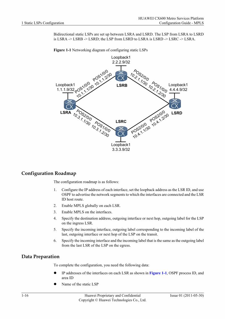
Bidirectional static LSPs are set up between LSRA and LSRD. The LSP from LSRA to LSRDis LSRA -> LSRB -> LSRD; the LSP from LSRD to LSRA is LSRD -> LSRC -> LSRA.
Figure 1-1 Networking diagram of configuring static LSPs
Loopback11.1.1.9/32
Loopback13.3.3.9/32
Loopback12.2.2.9/32
LSRA
Loopback14.4.4.9/32
LSRB
LSRC
LSRDPOS2/0/0
10.3.1.1/30
POS1/0/0
10.1.1.2/30POS2/0/0
10.2.1.1/30
POS1/0/010.3.1.2/30 POS2/0/0
10.4.1.1/30
POS1/0/010.2.1.2/30
POS2/0/0
10.4.1.2/30
POS1/0/0
10.1.1.1/30
Configuration RoadmapThe configuration roadmap is as follows:
1. Configure the IP address of each interface, set the loopback address as the LSR ID, and useOSPF to advertise the network segments to which the interfaces are connected and the LSRID host route.
2. Enable MPLS globally on each LSR.3. Enable MPLS on the interfaces.4. Specify the destination address, outgoing interface or next hop, outgoing label for the LSP
on the ingress LSR.5. Specify the incoming interface, outgoing label corresponding to the incoming label of the
last, outgoing interface or next hop of the LSP on the transit.6. Specify the incoming interface and the incoming label that is the same as the outgoing label
from the last LSR of the LSP on the egress.
Data PreparationTo complete the configuration, you need the following data:
l IP addresses of the interfaces on each LSR as shown in Figure 1-1, OSPF process ID, andarea ID
l Name of the static LSP
1 Static LSPs ConfigurationHUAWEI CX600 Metro Services Platform
Configuration Guide - MPLS
1-16 Huawei Proprietary and ConfidentialCopyright © Huawei Technologies Co., Ltd.
Issue 01 (2011-05-30)
l Outgoing label of the interfaces
Procedure
Step 1 Configure the IP address of each interface.
According to Figure 1-1, configure the IP address and the mask of the interfaces, including theloopback interface. The configuration details are not mentioned here.
Step 2 Use OSPF to advertise the network segments to which the interfaces are connected and the LSRID host route.
# Configure LSRA.
[LSRA] ospf 1[LSRA-ospf-1] area 0[LSRA-ospf-1-area-0.0.0.0] network 1.1.1.9 0.0.0.0[LSRA-ospf-1-area-0.0.0.0] network 10.1.1.0 0.0.0.3[LSRA-ospf-1-area-0.0.0.0] network 10.3.1.0 0.0.0.3[LSRA-ospf-1-area-0.0.0.0] quit[LSRA-ospf-1] quit
# Configure LSRB.
[LSRB] ospf 1[LSRB-ospf-1] area 0[LSRB-ospf-1-area-0.0.0.0] network 2.2.2.9 0.0.0.0[LSRB-ospf-1-area-0.0.0.0] network 10.1.1.0 0.0.0.3[LSRB-ospf-1-area-0.0.0.0] network 10.2.1.0 0.0.0.3[LSRB-ospf-1-area-0.0.0.0] quit[LSRB-ospf-1] quit
# Configure LSRC.
[LSRC] ospf 1[LSRC-ospf-1] area 0[LSRC-ospf-1-area-0.0.0.0] network 3.3.3.9 0.0.0.0[LSRC-ospf-1-area-0.0.0.0] network 10.3.1.0 0.0.0.3[LSRC-ospf-1-area-0.0.0.0] network 10.4.1.0 0.0.0.3[LSRC-ospf-1-area-0.0.0.0] quit[LSRC-ospf-1] quit
# Configure LSRD.
[LSRD] ospf 1[LSRD-ospf-1] area 0[LSRD-ospf-1-area-0.0.0.0] network 4.4.4.9 0.0.0.0[LSRD-ospf-1-area-0.0.0.0] network 10.2.1.0 0.0.0.3[LSRD-ospf-1-area-0.0.0.0] network 10.4.1.0 0.0.0.3[LSRD-ospf-1-area-0.0.0.0] quit[LSRD-ospf-1] quit
After the configuration, run the display ip routing-table command on the LSRs, and you canview that the LSRs already learn routes from each other.
Take the display on LSRA as an example.
[LSRA] display ip routing-tableRoute Flags: R - relay, D - download to fib------------------------------------------------------------------------------Routing Tables: Public Destinations : 14 Routes : 15Destination/Mask Proto Pre Cost Flags NextHop Interface 1.1.1.9/32 Direct 0 0 D 127.0.0.1 InLoopBack0 2.2.2.9/32 OSPF 10 2 D 10.1.1.2 Pos1/0/0 3.3.3.9/32 OSPF 10 2 D 10.3.1.2 Pos2/0/0 4.4.4.9/32 OSPF 10 3 D 10.1.1.2 Pos1/0/0
HUAWEI CX600 Metro Services PlatformConfiguration Guide - MPLS 1 Static LSPs Configuration
Issue 01 (2011-05-30) Huawei Proprietary and ConfidentialCopyright © Huawei Technologies Co., Ltd.
1-17
OSPF 10 3 D 10.3.1.2 Pos2/0/0 10.1.1.0/30 Direct 0 0 D 10.1.1.1 Pos1/0/0 10.1.1.1/32 Direct 0 0 D 127.0.0.1 InLoopBack0 10.1.1.2/32 Direct 0 0 D 10.1.1.2 Pos1/0/0 10.2.1.0/30 OSPF 10 2 D 10.1.1.2 Pos1/0/0 10.3.1.0/30 Direct 0 0 D 10.3.1.1 Pos2/0/0 10.3.1.1/32 Direct 0 0 D 127.0.0.1 InLoopBack0 10.3.1.2/32 Direct 0 0 D 10.3.1.2 Pos2/0/0 10.4.1.0/30 OSPF 10 2 D 10.3.1.2 Pos2/0/0 127.0.0.0/8 Direct 0 0 D 127.0.0.1 InLoopBack0 127.0.0.1/32 Direct 0 0 D 127.0.0.1 InLoopBack0
The next hop or outgoing interface of the static LSP on 4.4.4.9/32 from LSRA to LSRD isdetermined by the routing table. It is shown in boldface. In this example, the next hop IP addressis 10.1.1.2/30.
Take the display on LSRD as an example.
[LSRD] display ip routing-tableRoute Flags: R - relay, D - download to fib------------------------------------------------------------------------------Routing Tables: Public Destinations : 14 Routes : 15Destination/Mask Proto Pre Cost Flags NextHop Interface 1.1.1.9/32 OSPF 10 3 D 10.2.1.1 Pos1/0/0 OSPF 10 3 D 10.4.1.1 Pos2/0/0 2.2.2.9/32 OSPF 10 2 D 10.2.1.1 Pos1/0/0 3.3.3.9/32 OSPF 10 2 D 10.4.1.1 Pos2/0/0 4.4.4.9/32 Direct 0 0 D 127.0.0.1 InLoopBack0 10.1.1.0/30 OSPF 10 2 D 10.2.1.1 Pos1/0/0 10.2.1.0/30 Direct 0 0 D 10.2.1.2 Pos1/0/0 10.2.1.1/32 Direct 0 0 D 10.2.1.1 Pos1/0/0 10.2.1.2/32 Direct 0 0 D 127.0.0.1 InLoopBack0 10.3.1.0/30 OSPF 10 2 D 10.4.1.1 Pos2/0/0 10.4.1.0/30 Direct 0 0 D 10.4.1.2 Pos2/0/0 10.4.1.1/32 Direct 0 0 D 10.4.1.1 Pos2/0/0 10.4.1.2/32 Direct 0 0 D 127.0.0.1 InLoopBack0 127.0.0.0/8 Direct 0 0 D 127.0.0.1 InLoopBack0 127.0.0.1/32 Direct 0 0 D 127.0.0.1 InLoopBack0
The next hop or outgoing interface of the static LSP on 1.1.1.9/32 from LSRD to LSRA isdetermined by the routing table. It is shown in boldface. In this example, the next hop IP addressis 10.4.1.1/30.
Step 3 Configure the basic MPLS capability on each LSR.
# Configure LSRA.
[LSRA] mpls lsr-id 1.1.1.9[LSRA] mpls[LSRA-mpls] quit
# Configure LSRB.
[LSRB] mpls lsr-id 2.2.2.9[LSRB] mpls[LSRB-mpls] quit
# Configure LSRC.
[LSRC] mpls lsr-id 3.3.3.9[LSRC] mpls[LSRC-mpls] quit
# Configure LSRD.
[LSRD] mpls lsr-id 4.4.4.9[LSRD] mpls
1 Static LSPs ConfigurationHUAWEI CX600 Metro Services Platform
Configuration Guide - MPLS
1-18 Huawei Proprietary and ConfidentialCopyright © Huawei Technologies Co., Ltd.
Issue 01 (2011-05-30)
[LSRD-mpls] quit
Step 4 Configure the basic MPLS functions on each interface.
# Configure LSRA.
[LSRA] interface pos 1/0/0[LSRA-Pos1/0/0] mpls[LSRA-Pos1/0/0] quit[LSRA] interface pos 2/0/0[LSRA-Pos2/0/0] mpls[LSRA-Pos2/0/0] quit
# Configure LSRB.
[LSRB] interface pos 1/0/0[LSRB-Pos1/0/0] mpls[LSRB-Pos1/0/0] quit[LSRB] interface pos 2/0/0[LSRB-Pos2/0/0] mpls[LSRB-Pos2/0/0] quit
# Configure LSRC.
[LSRC] interface pos 1/0/0[LSRC-Pos1/0/0] mpls[LSRC-Pos1/0/0] quit[LSRC] interface pos 2/0/0[LSRC-Pos2/0/0] mpls[LSRC-Pos2/0/0] quit
# Configure LSRD.
[LSRD] interface pos 1/0/0[LSRD-Pos1/0/0] mpls[LSRD-Pos1/0/0] quit[LSRD] interface pos 2/0/0[LSRD-Pos2/0/0] mpls[LSRD-Pos2/0/0] quit
Step 5 Establish a static LSP from LSRA to LSRD.
# Configure the ingress LSRA.
[LSRA] static-lsp ingress RAtoRD destination 4.4.4.9 32 nexthop 10.1.1.2 out-label 20
# Configure the transit LSRB.
[LSRB] static-lsp transit RAtoRD incoming-interface pos 1/0/0 in-label 20 nexthop 10.2.1.2 out-label 40
# Configure the egress LSRD.
[LSRD] static-lsp egress RAtoRD incoming-interface pos 1/0/0 in-label 40
After the configuration, run the display mpls static-lsp verbose or display mpls lsp commandon the LSRs to view the status of the LSP.
Take the display on LSRA as an example.
[LSRA] display mpls static-lspTOTAL : 1 STATIC LSP(S)UP : 1 STATIC LSP(S)DOWN : 0 STATIC LSP(S)Name FEC I/O Label I/O If StatRAtoRD 4.4.4.9/32 NULL/20 -/Pos1/0/0 Up
As the LSP is unidirectional, you need to configure a static LSP from LSRD to LSRA.
HUAWEI CX600 Metro Services PlatformConfiguration Guide - MPLS 1 Static LSPs Configuration
Issue 01 (2011-05-30) Huawei Proprietary and ConfidentialCopyright © Huawei Technologies Co., Ltd.
1-19
Step 6 Establish the static LSP from LSRD to LSRA.
In the same method, configure the static LSP from LSRD to LSRA.
# Configure the ingress LSRD.
[LSRD] static-lsp ingress RDtoRA destination 1.1.1.9 32 nexthop 10.4.1.1 out-label 30
# Configure the transit LSRC.
[LSRC] static-lsp transit RDtoRA incoming-interface pos 2/0/0 in-label 30 nexthop 10.3.1.1 out-label 60
# Configure the egress LSRA.
[LSRA] static-lsp egress RDtoRA incoming-interface pos 2/0/0 in-label 60
Step 7 Verify the configuration
# After the configuration, run the ping lsp ip 1.1.1.9 32 on LSRD, and you can view that theLSP is reachable.
Run the display mpls static-lsp or display mpls static-lsp verbose command on the LSRs, andyou can view the status and the detailed information about the static LSP.
Take the output of LSRD as an example.
[LSRD] display mpls static-lspTOTAL : 2 STATIC LSP(S)UP : 2 STATIC LSP(S)DOWN : 0 STATIC LSP(S)Name FEC I/O Label I/O If StatRAtoRD -/- 40/NULL Pos1/0/0/- UpRDtoRA 1.1.1.9/32 NULL/30 -/Pos2/0/0 Up [LSRD] display mpls static-lsp verboseNo : 1LSP-Name : RAtoRDLSR-Type : EgressFEC : -/-In-Label : 40Out-Label : NULLIn-Interface : Pos1/0/0Out-Interface : -NextHop : -Static-Lsp Type: NormalLsp Status : UpNo : 2LSP-Name : RDtoRALSR-Type : IngressFEC : 1.1.1.9/32In-Label : NULLOut-Label : 30In-Interface : -Out-Interface : Pos2/0/0NextHop : 10.4.1.1Static-Lsp Type: NormalLsp Status : Up
----End
Configuration Filesl Configuration file of LSRA
# sysname LSRA#
1 Static LSPs ConfigurationHUAWEI CX600 Metro Services Platform
Configuration Guide - MPLS
1-20 Huawei Proprietary and ConfidentialCopyright © Huawei Technologies Co., Ltd.
Issue 01 (2011-05-30)
mpls lsr-id 1.1.1.9 mpls#interface Pos1/0/0 link-protocol ppp undo shutdown ip address 10.1.1.1 255.255.255.252 mpls#interface Pos2/0/0 link-protocol ppp undo shutdown ip address 10.3.1.1 255.255.255.252 mpls#interface LoopBack1 ip address 1.1.1.9 255.255.255.255#ospf 1 area 0.0.0.0 network 1.1.1.9 0.0.0.0 network 10.1.1.0 0.0.0.3 network 10.3.1.0 0.0.0.3# static-lsp ingress RAtoRD destination 4.4.4.9 32 nexthop 10.1.1.2 out-label 20 static-lsp egress RDtoRA incoming-interface Pos2/0/0 in-label 60#return
l Configuration file of LSRB# sysname LSRB# mpls lsr-id 2.2.2.9 mpls#interface Pos1/0/0 link-protocol ppp undo shutdown ip address 10.1.1.2 255.255.255.252 mpls#interface Pos2/0/0 link-protocol ppp undo shutdown ip address 10.2.1.1 255.255.255.252 mpls#interface LoopBack1 ip address 2.2.2.9 255.255.255.255#ospf 1 area 0.0.0.0 network 2.2.2.9 0.0.0.0 network 10.1.1.0 0.0.0.3 network 10.2.1.0 0.0.0.3#static-lsp transit RAtoRD incoming-interface Pos1/0/0 in-label 20 nexthop 10.2.1.2 out-label 40#return
l Configuration file of LSRC# sysname LSRC# mpls lsr-id 3.3.3.9 mpls#interface Pos1/0/0
HUAWEI CX600 Metro Services PlatformConfiguration Guide - MPLS 1 Static LSPs Configuration
Issue 01 (2011-05-30) Huawei Proprietary and ConfidentialCopyright © Huawei Technologies Co., Ltd.
1-21
link-protocol ppp undo shutdown ip address 10.3.1.2 255.255.255.252 mpls#interface Pos2/0/0 link-protocol ppp undo shutdown ip address 10.4.1.1 255.255.255.252 mpls#interface LoopBack1 ip address 3.3.3.9 255.255.255.255#ospf 1 area 0.0.0.0 network 3.3.3.9 0.0.0.0 network 10.3.1.0 0.0.0.3 network 10.4.1.0 0.0.0.3#static-lsp transit RDtoRA incoming-interface Pos2/0/0 in-label 30 nexthop 10.3.1.1 out-label 60#return
l Configuration file of LSRD# sysname LSRD# mpls lsr-id 4.4.4.9 mpls#interface Pos1/0/0 link-protocol ppp undo shutdown ip address 10.2.1.2 255.255.255.252 mpls#interface Pos2/0/0 link-protocol ppp undo shutdown ip address 10.4.1.2 255.255.255.252 mpls#interface LoopBack1 ip address 4.4.4.9 255.255.255.255#ospf 1 area 0.0.0.0 network 4.4.4.9 0.0.0.0 network 10.2.1.0 0.0.0.3 network 10.4.1.0 0.0.0.3# static-lsp egress RAtoRD incoming-interface Pos1/0/0 in-label 40 static-lsp ingress RDtoRA destination 1.1.1.9 32 nexthop 10.4.1.1 out-label 30#return
1.5.2 Example for Configuring Static BFD for Static LSPThis section provides an example for setting up a static LSP and configuring a static BFD sessionfor detecting the static LSP.
Networking Requirements
As shown in Figure 1-2:
1 Static LSPs ConfigurationHUAWEI CX600 Metro Services Platform
Configuration Guide - MPLS
1-22 Huawei Proprietary and ConfidentialCopyright © Huawei Technologies Co., Ltd.
Issue 01 (2011-05-30)
l PE1, PE2, P1, and P2 are in one MPLS domain.l A static LSP is set up along the path PE1 -> P1 ->PE2.
Without MPLS OAM, test the connectivity of the static LSP. When the static LSP fails, PE1can receive the advertisement within 50 ms.
Figure 1-2 Networking diagram of configuring static BFD for static LSP
Loopback11.1.1.1/32
Loopback13.3.3.3/32
Loopback12.2.2.2/32
PE1
Loopback14.4.4.4/32
P1
P2
PE2POS1/0/110.1.2.1/24
POS1/0/0
10.1.1.2/24POS1/0/2
10.1.5.2/24
POS1/0/010.1.2.2/24 POS1/0/2
10.1.4.2/24
POS1/0/010.1.5.1/24
POS1/0/1
10.1.4.1/24
POS1/0/0
10.1.1.1/24
Static LSP
Configuration RoadmapThe configuration roadmap is as follows:
1. The entire MPLS domain applies OSPF protocol and IP route is accessible to each LSR.2. Configure the BFD session on PE1 to detect the static LSP.3. Configure the BFD session on PE2, which advertises a failure on static LSP to PE1 (in this
direction, the link is an IP link).
Data PreparationsTo complete the configuration, you need the following data:
l IP addresses of the interfaces on each LSRl OSPF process numberl BFD session parameters, such as configuration name, minimum detection interval between
sending and receiving packets
Procedure
Step 1 Configure the IP address and the OSPF protocol for each interface.
HUAWEI CX600 Metro Services PlatformConfiguration Guide - MPLS 1 Static LSPs Configuration
Issue 01 (2011-05-30) Huawei Proprietary and ConfidentialCopyright © Huawei Technologies Co., Ltd.
1-23
Configure the IP address and mask of each interface as shown in Figure 1-2, including loopbackinterfaces.
Configure OSPF on all LSRs to advertise the host route of the loopback interface. The detailedconfiguration is not mentioned here.
After the configuration, each LSR can ping through the other LSR ID. Run the display iprouting-table command, and you can view the route table on each LSR.
<PE1> display ip routing-tableRoute Flags: R - relay, D - download to fib------------------------------------------------------------------------------Routing Tables: Public Destinations : 14 Routes : 15Destination/Mask Proto Pre Cost Flags NextHop Interface 1.1.1.1/32 Direct 0 0 127.0.0.1 InLoopBack0 2.2.2.2/32 OSPF 10 2 10.1.1.2 Pos1/0/0 3.3.3.3/32 OSPF 10 2 10.1.2.2 Pos1/0/1 4.4.4.4/32 OSPF 10 3 10.1.1.2 Pos1/0/0 OSPF 10 3 10.1.2.2 Pos1/0/1 10.1.1.0/24 Direct 0 0 10.1.1.1 Pos1/0/0 10.1.1.1/32 Direct 0 0 127.0.0.1 InLoopBack0 10.1.1.2/32 Direct 0 0 10.1.1.2 Pos1/0/0 10.1.2.0/24 Direct 0 0 10.1.2.1 Pos1/0/1 10.1.2.1/32 Direct 0 0 127.0.0.1 InLoopBack0 10.1.2.2/32 Direct 0 0 10.1.2.2 Pos1/0/1 10.1.4.0/24 OSPF 10 2 10.1.2.2 Pos1/0/1 10.1.5.0/24 OSPF 10 2 10.1.1.2 Pos1/0/0 127.0.0.0/8 Direct 0 0 127.0.0.1 InLoopBack0 127.0.0.1/32 Direct 0 0 127.0.0.1 InLoopBack0
Step 2 Enable the MPLS and BFD functions on each LSR.
# Enable MPLS on PE1 globally and enable MPLS on each interface.
<PE1> system-view[PE1] mpls lsr-id 1.1.1.1[PE1] mpls[PE1-mpls] quit[PE1] interface pos 1/0/0[PE1-Pos1/0/0] mpls[PE1-Pos1/0/0] quit[PE1] interface pos 1/0/1[PE1-Pos1/0/1] mpls[PE1-Pos1/0/1] quit
# Enable BFD on PE1 globally.
[PE1] bfd[PE1-bfd] quit
Repeat preceding steps on PE2, P1, and P2.
Step 3 Create a static LSP with PE1 being the ingress and PE2 being the egress.
# Configure a static LSP on PE1 (ingress) named 1to4.
[PE1] static-lsp ingress 1to4 destination 4.4.4.4 32 nexthop 10.1.1.2 out-label 20
# Configure a static LSP on P1 (transit).
[P1] static-lsp transit 1to4 incoming-interface pos 1/0/0 in-label 20 nexthop 10.1.5.1 out-label 30
# Configure a static LSP on PE2 (egress).
[PE2] static-lsp egress 1to4 incoming-interface pos 1/0/0 in-label 30
1 Static LSPs ConfigurationHUAWEI CX600 Metro Services Platform
Configuration Guide - MPLS
1-24 Huawei Proprietary and ConfidentialCopyright © Huawei Technologies Co., Ltd.
Issue 01 (2011-05-30)
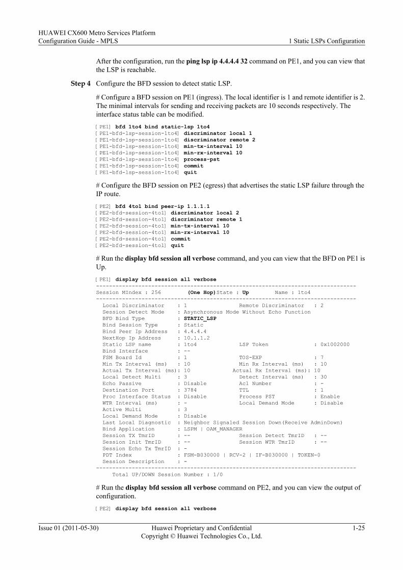
After the configuration, run the ping lsp ip 4.4.4.4 32 command on PE1, and you can view thatthe LSP is reachable.
Step 4 Configure the BFD session to detect static LSP.
# Configure a BFD session on PE1 (ingress). The local identifier is 1 and remote identifier is 2.The minimal intervals for sending and receiving packets are 10 seconds respectively. Theinterface status table can be modified.
[PE1] bfd 1to4 bind static-lsp 1to4[PE1-bfd-lsp-session-1to4] discriminator local 1[PE1-bfd-lsp-session-1to4] discriminator remote 2[PE1-bfd-lsp-session-1to4] min-tx-interval 10[PE1-bfd-lsp-session-1to4] min-rx-interval 10[PE1-bfd-lsp-session-1to4] process-pst[PE1-bfd-lsp-session-1to4] commit[PE1-bfd-lsp-session-1to4] quit
# Configure the BFD session on PE2 (egress) that advertises the static LSP failure through theIP route.
[PE2] bfd 4to1 bind peer-ip 1.1.1.1[PE2-bfd-session-4to1] discriminator local 2[PE2-bfd-session-4to1] discriminator remote 1[PE2-bfd-session-4to1] min-tx-interval 10[PE2-bfd-session-4to1] min-rx-interval 10[PE2-bfd-session-4to1] commit[PE2-bfd-session-4to1] quit
# Run the display bfd session all verbose command, and you can view that the BFD on PE1 isUp.
[PE1] display bfd session all verbose--------------------------------------------------------------------------------Session MIndex : 256 (One Hop)State : Up Name : 1to4-------------------------------------------------------------------------------- Local Discriminator : 1 Remote Discriminator : 2 Session Detect Mode : Asynchronous Mode Without Echo Function BFD Bind Type : STATIC_LSP Bind Session Type : Static Bind Peer Ip Address : 4.4.4.4 NextHop Ip Address : 10.1.1.2 Static LSP name : 1to4 LSP Token : 0x1002000 Bind Interface : -- FSM Board Id : 1 TOS-EXP : 7 Min Tx Interval (ms) : 10 Min Rx Interval (ms) : 10 Actual Tx Interval (ms): 10 Actual Rx Interval (ms): 10 Local Detect Multi : 3 Detect Interval (ms) : 30 Echo Passive : Disable Acl Number : - Destination Port : 3784 TTL : 1 Proc Interface Status : Disable Process PST : Enable WTR Interval (ms) : - Local Demand Mode : Disable Active Multi : 3 Local Demand Mode : Disable Last Local Diagnostic : Neighbor Signaled Session Down(Receive AdminDown) Bind Application : LSPM | OAM_MANAGER Session TX TmrID : -- Session Detect TmrID : -- Session Init TmrID : -- Session WTR TmrID : -- Session Echo Tx TmrID : - PDT Index : FSM-B030000 | RCV-2 | IF-B030000 | TOKEN-0 Session Description : - -------------------------------------------------------------------------------- Total UP/DOWN Session Number : 1/0
# Run the display bfd session all verbose command on PE2, and you can view the output ofconfiguration.
[PE2] display bfd session all verbose
HUAWEI CX600 Metro Services PlatformConfiguration Guide - MPLS 1 Static LSPs Configuration
Issue 01 (2011-05-30) Huawei Proprietary and ConfidentialCopyright © Huawei Technologies Co., Ltd.
1-25
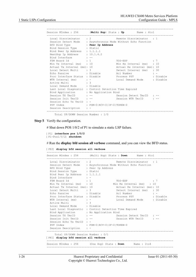
--------------------------------------------------------------------------------Session MIndex : 256 (Multi Hop) State : Up Name : 4to1-------------------------------------------------------------------------------- Local Discriminator : 2 Remote Discriminator : 1 Session Detect Mode : Asynchronous Mode Without Echo Function BFD Bind Type : Peer Ip Address Bind Session Type : Static Bind Peer Ip Address : 1.1.1.1 NextHop Ip Address : 10.1.4.2 Bind Interface : -- FSM Board Id : 1 TOS-EXP : 7 Min Tx Interval (ms) : 10 Min Rx Interval (ms) : 10 Actual Tx Interval (ms): 10 Actual Rx Interval (ms): 10 Local Detect Multi : 3 Detect Interval (ms) : 30 Echo Passive : Disable Acl Number : - Proc Interface Status : Disable Process PST : Disable WTR Interval (ms) : - Local Demand Mode : Disable Active Multi : 3 Local Demand Mode : Disable Last Local Diagnostic : Control Detection Time Expired Bind Application : No Application Bind Session TX TmrID : -- Session Detect TmrID : -- Session Init TmrID : -- Session WTR TmrID : -- Session Echo Tx TmrID : - PDT Index : FSM-0|RCV-0|IF-0|TOKEN-0 Session Description : - -------------------------------------------------------------------------------- Total UP/DOWN Session Number : 1/0
Step 5 Verify the configuration.
# Shut down POS 1/0/2 of P1 to simulate a static LSP failure.
[P1] interface pos 1/0/2[P1-Pos1/0/2] shutdown
# Run the display bfd session all verbose command, and you can view the BFD status.
[PE2] display bfd session all verbose--------------------------------------------------------------------------------Session MIndex : 256 (Multi Hop) State : Down Name : 4to1-------------------------------------------------------------------------------- Local Discriminator : 2 Remote Discriminator : 1 Session Detect Mode : Asynchronous Mode Without Echo Function BFD Bind Type : Peer Ip Address Bind Session Type : Static Bind Peer Ip Address : 1.1.1.1 Bind Interface : - FSM Board Id : 1 TOS-EXP : 7 Min Tx Interval (ms) : 10 Min Rx Interval (ms) : 10 Actual Tx Interval (ms): 10 Actual Rx Interval (ms): 10 Local Detect Multi : 3 Detect Interval (ms) : 30 Echo Passive : Disable Acl Number : - Proc Interface Status : Disable Process PST : Disable WTR Interval (ms) : - Local Demand Mode : Disable Active Multi : 3 Local Demand Mode : Disable Last Local Diagnostic : Control Detection Time Expired Bind Application : No Application Bind Session TX TmrID : -- Session Detect TmrID : -- Session Init TmrID : -- Session WTR TmrID : -- Session Echo Tx TmrID : - PDT Index : FSM-0|RCV-0|IF-0|TOKEN-0 Session Description : - -------------------------------------------------------------------------------- Total UP/DOWN Session Number : 0/1[PE1] display bfd session all verbose--------------------------------------------------------------------------------Session MIndex : 256 (One Hop) State : Down Name : 1to4--------------------------------------------------------------------------------
1 Static LSPs ConfigurationHUAWEI CX600 Metro Services Platform
Configuration Guide - MPLS
1-26 Huawei Proprietary and ConfidentialCopyright © Huawei Technologies Co., Ltd.
Issue 01 (2011-05-30)
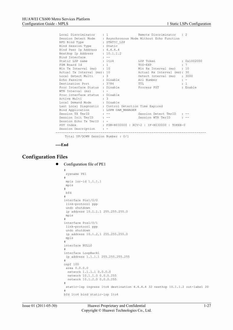
Local Discriminator : 1 Remote Discriminator : 2 Session Detect Mode : Asynchronous Mode Without Echo Function BFD Bind Type : STATIC_LSP Bind Session Type : Static Bind Peer Ip Address : 4.4.4.4 NextHop Ip Address : 10.1.1.2 Bind Interface : -- Static LSP name : 1to4 LSP Token : 0x1002000 FSM Board Id : 1 TOS-EXP : 7 Min Tx Interval (ms) : 10 Min Rx Interval (ms) : 10 Actual Tx Interval (ms): 10 Actual Rx Interval (ms): 30 Local Detect Multi : 3 Detect Interval (ms) : 3000 Echo Passive : Disable Acl Number : - Destination Port : 3784 TTL : 1 Proc Interface Status : Disable Process PST : Enable WTR Interval (ms) : - Proc interface status : Disable Active Multi : 3 Local Demand Mode : Disable Last Local Diagnostic : Control Detection Time Expired Bind Application : LSPM OAM_MANAGER Session TX TmrID : -- Session Detect TmrID : -- Session Init TmrID : -- Session WTR TmrID : -- Session Echo Tx TmrID : - PDT Index : FSM-B030000 | RCV-2 | IF-B030000 | TOKEN-0 Session Description : - -------------------------------------------------------------------------------- Total UP/DOWN Session Number : 0/1
----End
Configuration Filesl Configuration file of PE1
# sysname PE1# mpls lsr-id 1.1.1.1 mpls# bfd#interface Pos1/0/0 link-protocol ppp undo shutdown ip address 10.1.1.1 255.255.255.0 mpls#interface Pos1/0/1 link-protocol ppp undo shutdown ip address 10.1.2.1 255.255.255.0 mpls#interface NULL0#interface LoopBack1 ip address 1.1.1.1 255.255.255.255#ospf 100 area 0.0.0.0 network 1.1.1.1 0.0.0.0 network 10.1.1.0 0.0.0.255 network 10.1.2.0 0.0.0.255# static-lsp ingress 1to4 destination 4.4.4.4 32 nexthop 10.1.1.2 out-label 20#bfd 1to4 bind static-lsp 1to4
HUAWEI CX600 Metro Services PlatformConfiguration Guide - MPLS 1 Static LSPs Configuration
Issue 01 (2011-05-30) Huawei Proprietary and ConfidentialCopyright © Huawei Technologies Co., Ltd.
1-27
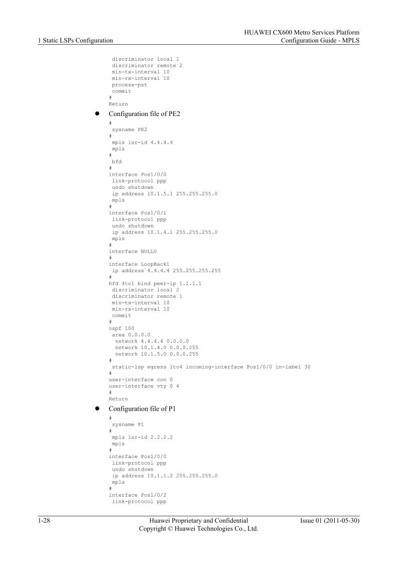
discriminator local 1 discriminator remote 2 min-tx-interval 10 min-rx-interval 10 process-pst commit#Return
l Configuration file of PE2# sysname PE2# mpls lsr-id 4.4.4.4 mpls# bfd#interface Pos1/0/0 link-protocol ppp undo shutdown ip address 10.1.5.1 255.255.255.0 mpls#interface Pos1/0/1 link-protocol ppp undo shutdown ip address 10.1.4.1 255.255.255.0 mpls#interface NULL0#interface LoopBack1 ip address 4.4.4.4 255.255.255.255#bfd 4to1 bind peer-ip 1.1.1.1 discriminator local 2 discriminator remote 1 min-tx-interval 10 min-rx-interval 10 commit#ospf 100 area 0.0.0.0 network 4.4.4.4 0.0.0.0 network 10.1.4.0 0.0.0.255 network 10.1.5.0 0.0.0.255# static-lsp egress 1to4 incoming-interface Pos1/0/0 in-label 30#user-interface con 0user-interface vty 0 4#Return
l Configuration file of P1# sysname P1# mpls lsr-id 2.2.2.2 mpls#interface Pos1/0/0 link-protocol ppp undo shutdown ip address 10.1.1.2 255.255.255.0 mpls#interface Pos1/0/2 link-protocol ppp
1 Static LSPs ConfigurationHUAWEI CX600 Metro Services Platform
Configuration Guide - MPLS
1-28 Huawei Proprietary and ConfidentialCopyright © Huawei Technologies Co., Ltd.
Issue 01 (2011-05-30)
undo shutdown ip address 10.1.5.2 255.255.255.0 mpls#interface LoopBack1 ip address 2.2.2.2 255.255.255.255#ospf 100 area 0.0.0.0 network 2.2.2.2 0.0.0.0 network 10.1.1.0 0.0.0.255 network 10.1.5.0 0.0.0.255# static-lsp transit 1to4 incoming-interface Pos1/0/0 in-label 20 nexthop 10.1.5.1 out-label 30#return
l Configuration file of P2# sysname P2# mpls lsr-id 3.3.3.3 mpls#interface Pos1/0/0 link-protocol ppp undo shutdown ip address 10.1.2.2 255.255.255.0 mpls#interface Pos1/0/2 link-protocol ppp undo shutdown ip address 10.1.4.2 255.255.255.0 mpls#interface LoopBack1 ip address 3.3.3.3 255.255.255.255#ospf 100 area 0.0.0.0 network 3.3.3.3 0.0.0.0 network 10.1.2.0 0.0.0.255 network 10.1.4.0 0.0.0.255#return
HUAWEI CX600 Metro Services PlatformConfiguration Guide - MPLS 1 Static LSPs Configuration
Issue 01 (2011-05-30) Huawei Proprietary and ConfidentialCopyright © Huawei Technologies Co., Ltd.
1-29

2 MPLS LDP Configuration
About This Chapter
MPLS LDP defines the messages during label distribution and the processing of the messagesthat are used to negotiate parameters between LSRs and allocate labels to set up an LSP.
2.1 Introduction to MPLS LDPMPLS LDP, a label distribution protocol, is used to provide VPN services. MPLS LDP simplifiesthe networking and configurations, supports the establishment of LSPs through the triggeringof routes, and supports a great number of LSPs.
2.2 Configuring LDP SessionsAn MPLS LDP session can be set up only after a device is configured with an LSR ID andenabled with MPLS LDP.
2.3 Configuring LDP LSPLDP is a label distribution protocol in an MPLS domain to distribute labels during the setup ofan LSP.
2.4 Configuring LDP Extension for Inter-Area LSPConfiguring LDP Extension for Inter-Area LSP enables LDP to search for routes according tothe longest match rule to establish inter-area LDP LSPs.
2.5 Configuring the LDP Multi-InstanceYou need to configure the LDP multi-instance when deploying the BGP/MPLS IP VPN.
2.6 Configuring Static BFD for LDP LSPBy configuring a static BFD session to detect an LDP LSP, you can detect LSP connectivityaccording to specified parameters.
2.7 Configuring Dynamic BFD for LDP LSPBy configuring a dynamic BFD session to detect an LDP LSP, you does not need to configureBFD parameters. This can speed up link fault detection and reduce workload on configurations.
2.8 Configuring Manual LDP FRRBy configuring Manual LDP FRR, you can quickly switch traffic to the backup LSP when a linkfails, which ensures uninterrupted traffic transmission.
2.9 Configuring LDP Auto FRR
HUAWEI CX600 Metro Services PlatformConfiguration Guide - MPLS 2 MPLS LDP Configuration
Issue 01 (2011-05-30) Huawei Proprietary and ConfidentialCopyright © Huawei Technologies Co., Ltd.
2-1
By configuring a policy for triggering the setup of backup LSPs, you can control the setup ofbackup LSPs.
2.10 Configuring Synchronization Between LDP and IGPBy configuring LDP and IGP synchronization, you can delay the route switchback bysuppressing the setup of IGP neighbor relationship till an LDP session is established.
2.11 Configuring Synchronization Between LDP and Static RoutesBy configuring synchronization between LDP and static routes, you can switch traffic from thefaulty primary link to the backup link by suppressing the activation of static routes and delaytraffic switchback to synchronize LDP and static routes.
2.12 Configuring LDP GTSMBy configuring LDP GTSM, you can detect TTLs to prevent attacks.
2.13 Configuring LDP GRBy configuring LDP GR, you can realize the uninterrupted forwarding during the master/slaveswitchover or the protocol restart, which can limit the protocol flapping on the control plane.
2.14 Maintaining MPLS LDPThe operations of MPLS LDP maintenance include deleting MPLS statistics, detectingconnectivity and reachability of an LSP, and configuring the trap function on an LDP LSP.
2.15 Configuration ExamplesThe following sections provide several examples for configuring MPLS LDP. Familiarizeyourself with the configuration procedures against the networking diagram. Each configurationexample consists of the networking requirements, configuration precautions, configurationroadmap, configuration procedures, and configuration files.
2 MPLS LDP ConfigurationHUAWEI CX600 Metro Services Platform
Configuration Guide - MPLS
2-2 Huawei Proprietary and ConfidentialCopyright © Huawei Technologies Co., Ltd.
Issue 01 (2011-05-30)
2.1 Introduction to MPLS LDPMPLS LDP, a label distribution protocol, is used to provide VPN services. MPLS LDP simplifiesthe networking and configurations, supports the establishment of LSPs through the triggeringof routes, and supports a great number of LSPs.
2.1.1 MPLS LDP OverviewThrough LDP, LSRs (Label Switched Router) can map the route information at the networklayer to the switched paths at the data link layer to set up network layer LSPs.
2.1.2 MPLS LDP Features Supported by the CX600MPLS LDP features supported by the system include LDP sessions, LDP LSPs, LDP multi-instance , BFD for LDP LSPs, LDP FRR, LDP GR, LDP and IGP synchronization, and LDPGTSM.
2.1.1 MPLS LDP OverviewThrough LDP, LSRs (Label Switched Router) can map the route information at the networklayer to the switched paths at the data link layer to set up network layer LSPs.
With the prevalence of the Internet early in the 1990s, the IP technology that adopts the longestmatch for search becomes a bottleneck in forwarding over networks due to limitation of thehardware technology. The ATM (Asynchronous Transfer Mode) technology uses labels withfixed lengths and maintains a label table with a size much smaller than the size of the routingtable. Therefore, compared with IP technology, the ATM technology supports better forwardingperformance.
The traditional IP technology is simple to implement but limited in performance. The ATMtechnology has better performance but is difficult to popularize because of its complex signalingand high cost in deployment. The MPLS (Multiprotocol Label Switching) technology thusemerges to combine the advantages of IP and ATM technologies.
Initially, MPLS emerges to speed up the forwarding of the device. With the development of theASIC (Application Specific Integrated Circuit) technology, the speed of routing is not thebottleneck to the network development. MPLS, however, does not feature in high-speedforwarding. As MPLS supports multi-layer labels, the connection-oriented forwarding plane,and the connectionless-oriented control plane, MPLS is widely used in VPN (Virtual PrivateNetwork), TE (Traffic Engineering), and QoS (Quality of Service).
2.1.2 MPLS LDP Features Supported by the CX600MPLS LDP features supported by the system include LDP sessions, LDP LSPs, LDP multi-instance , BFD for LDP LSPs, LDP FRR, LDP GR, LDP and IGP synchronization, and LDPGTSM.
LDP Sessions
Label Distribution Protocol (LDP) sessions are used between LSRs to swap labels.
l Local LDP session: can be set up only between adjacent LSRs.
l Remote LDP session: can be set between adjacent LSRs or non-adjacent LSRs.
HUAWEI CX600 Metro Services PlatformConfiguration Guide - MPLS 2 MPLS LDP Configuration
Issue 01 (2011-05-30) Huawei Proprietary and ConfidentialCopyright © Huawei Technologies Co., Ltd.
2-3
LDP LSPThe LDP protocol is used to create dynamic LSPs. If you need not to strictly control the setupprocess of LSPs or to deploy traffic engineering (TE) on an MPLS network, you arerecommended to use LDP to set up LSPs.
LDP Multi-InstanceLDP multi-instance is applicable to the networking of MPLS L3VPN carrier's carrier. For detailsof carrier's carrier networking, refer to the HUAWEI CX600 Metro Services Platform FeatureDescription - VPN.
BFD for LDP LSPBFD can detect faults on the data plane of the LDP LSP forwarding path. At the same time, theformat of BFD packets is constant, adaptive to implementation in hardware and traversal throughthe firewall. The advantages of BFD for the data plane of LDP LSP are as follows:
l Quick detectionl Wide range of failure detection for LSPs
At present, in the CX600, BFD can detect LSPs of the following types:
l Static LSPl LDP LSPl TE tunnel
BFD for LSP is dedicated to public bear layer of VPN/PW and provides reliability to applicationsbased on MPLS network, such as VPN FRR, TE FRR, and VLL FRR, to protect services.
When BFD works in unidirectional links, such as LSP and TE, only the IP route along thebackward link needs to be reachable. Therefore, the backward link can be IP tunnels, LSPs, orTE tunnels.
LDP FRRThe traditional IP Fast Reroute (FRR) cannot effectively protect the traffic on an MPLS network.The CX600 provides the LDP FRR function as a solution to port protection.
When the network works normally, packets are forwarded through the primary LSP. When theoutgoing interface of the primary LSP is Down, packets are forwarded through the bypass LSP.This ensures continuous traffic for a short time before network convergence completes. TheCX600 supports the LDP FRR in primary/bypass LSP mode rather than in load balancing mode.
LDP FRR supports BFD to implement quick fault detection. For details of BFD, refer to Chapter5 "BFD Configuration" in the HUAWEI CX600 Metro Services Platform Configuration Guide- Reliability.
LDP and IGP SynchronizationOn a network consisting of active and standby links, when an active link fails, traffic is switchedfrom the active link to the standby link and the traffic interruption takes about hundreds ofmilliseconds. When the active link recovers from the fault, the traffic is switched back to theactive link from the standby link and the traffic interruption takes about 5 seconds.
2 MPLS LDP ConfigurationHUAWEI CX600 Metro Services Platform
Configuration Guide - MPLS
2-4 Huawei Proprietary and ConfidentialCopyright © Huawei Technologies Co., Ltd.
Issue 01 (2011-05-30)
When LDP is synchronized with an IGP, the interruption duration when traffic is switched backto the active link is shortened to milliseconds.
The basic principle of LDP and IGP synchronization is to delay the switchback of the route byholding back the IGP neighbor establishment, and the latency depends on when the LDPconvergence completes. That is, before LSPs of the active link are established, traffic isforwarded through the standby link. After the active link is established, the standby link can bedeleted.
Synchronization Between LDP and Static RoutesOn an MPLS network with primary and backup LSPs, LSRs establish LSPs based on staticroutes. When the primary link becomes faulty, traffic is switched from the primary link to thebackup link. In this process, traffic is interrupted for about several hundred milliseconds. Afterthe primary link recovers, traffic is switched back from the backup link to the primary link. Inthis process, traffic is interrupted for about several seconds.
Configuring synchronization between LDP and static routes ensures millisecond-level trafficinterruption when traffic is switched back from the backup link to the primary link.
The basic principle of synchronization between LDP and static routes is to switch traffic fromthe faulty primary link to the backup link by suppressing the activation of static routes and delaytraffic switchback to synchronize the forwarding path of static routes with the LSP.
LDP GTSMThe Generalized TTL Security Mechanism (GTSM) protects the service above the IP layer bychecking whether the TTL value in the IP packet header is within a pre-set range. In applications,GTSM is designed to protect the TCP/IP-based control plane (like routing protocols) from CPU-usage attacks, such as CPU overload attacks.
LDP GRGraceful Restart (GR) is a key technology to HA implementation. At present, GR is widelyapplied to switchover and system upgrade.
The CX600 supports LDP GR. When the system performs the switchover, the interface boardis not reset and the LDP LSP information on the data plane is stored. In this manner, the LSPforwarding continues and the impact on forwarding the MPLS packets is minimized.
2.2 Configuring LDP SessionsAn MPLS LDP session can be set up only after a device is configured with an LSR ID andenabled with MPLS LDP.
2.2.1 Establishing the Configuration TaskBefore configuring an MPLS LDP session, familiarize yourself with the applicable environment,complete the pre-configuration tasks, and obtain the required data. This can help you rapidlyand correctly finish the configuration task.
2.2.2 Configuring the LSR IDBefore enabling MPLS, you must configure LSR ID.
2.2.3 Enabling MPLSMPLS LDP can be enabled only after MPLS is enabled.
HUAWEI CX600 Metro Services PlatformConfiguration Guide - MPLS 2 MPLS LDP Configuration
Issue 01 (2011-05-30) Huawei Proprietary and ConfidentialCopyright © Huawei Technologies Co., Ltd.
2-5

2.2.4 Enable Global MPLS LDPAn MPLS LDP session can be set up only after MPLS LDP is enabled.
2.2.5 (Optional) Configuring the LDP Dynamic Capability Announcement FunctionThe dynamic LDP negotiation capability dynamically enables or disables LDP features thatsupport dynamic negotiation without interrupting an LDP session, ensuring the stability of theLSP associated with the LDP session.
2.2.6 Configuring LDP SessionsMPLS LDP sessions are classified into the locate LDP session and the remote LDP session.
2.2.7 (Optional) Configuring LDP Transport AddressesLSRs need to confirm the transport address of the neighbor before an LDP session is set upbetween LSRs. By default, a transport address of an LSR is the LSR ID.
2.2.8 (Optional) Configuring LDP TimersLDP timers are classified into Hello hold timer, Hello send timer, Keepalive hold timer,Keepalive send timer, and the Exponential backoff timer, which can be configured as required.
2.2.9 (Optional) Configuring LDP MD5 AuthenticationYou can configure LDP MD5 authentication to improve security of the LDP session connection.
2.2.10 (Optional) Configuring LDP AuthenticationAfter LDP authentication is configured, the security of the connection of an LDP session isimproved. LDP authentication is configured on LSRs on both ends of an LDP session.
2.2.11 Checking the ConfigurationAfter an MPLS LDP session is successfully set up, you can view information about the interfaceenabled with MPLS and MPLS LDP, LDP, the LDP session status, the LDP session peers, andthe remote peer of the LDP session.
2.2.1 Establishing the Configuration TaskBefore configuring an MPLS LDP session, familiarize yourself with the applicable environment,complete the pre-configuration tasks, and obtain the required data. This can help you rapidlyand correctly finish the configuration task.
Applicable Environment
LDP sessions are classified into local LDP sessions and remote LDP sessions. These sessionsare applicable to the following scenarios:
l Setting up an LDP LSP through local LDP sessions
Before setting up an LDP LSP, you must set up LDP sessions between all directly connectedLSRs on the LSP to be set up. For details of LDP LSPs, see Configuring LDP LSP.
l Allocating inner labels for L2VPN
If a VLL or VPLS needs to be created in Martini mode between two LSRs, an LDP sessionmust be set up between the two LSRs before they assign inner labels for each other. Fordetails of L2VPN configuration, refer to the HUAWEI CX600 Metro Services PlatformConfiguration Guide - VPN.
l Configuring LDP over TE
On an MPLS network, if the core devices support TE and edge devices use LDP, you needto configure the remote LDP session between two edge LSRs. After LDP over TE is
2 MPLS LDP ConfigurationHUAWEI CX600 Metro Services Platform
Configuration Guide - MPLS
2-6 Huawei Proprietary and ConfidentialCopyright © Huawei Technologies Co., Ltd.
Issue 01 (2011-05-30)
enabled, the entire TE tunnel is regarded as a hop along the LDP LSP. For details of LDPover TE, see Configuring LDP over TE.
In addition, the CX600 also supports the following attributes:
l LDP transport addresses
LDP sessions are created on the basis of TCP connection. Before setting up an LDP session,two LSRs need to confirm the LDP transport address of each other, and then set up the TCPconnection.
Generally, it is not recommended to change the LDP transport address.
l LDP timers
– Hello hold timer
– Hello send timer
It is used together with the Hello hold timer to maintain LDP Hello adjacencies.
– Keepalive hold timer
– Keepalive send timer
It is used together with the Keepalive hold timer to maintain LDP sessions.
– Exponential backoff timer
It is used to control the interval for the active role to retry setting up an LDP session.
l MD5 authentication
It is used to improve the security of LDP sessions. A session is set up between two LSRssuccessfully only when passwords on both ends are consistent.
l Keychain authentication
Keychain, an enhanced encryption algorithm, calculates a message digest for an LDPmessage to prevent the message from being modified. The system automatically adopts anew password after the previous password expires, preventing the password from beingdecrypted.
Pre-configuration Tasks
Before configuring MPLS LDP sessions, complete the following tasks:
l Configuring a static route or IGP to connect LSRs on the network layer
Data Preparation
To configure MPLS LDP sessions, you need the following data.
No. Data
1 LSR ID of each node
2 Name and number of the interface on which an LDP session is to be set up
3 Name and IP address of the remote peer on which a remote LDP session is to beset up
4 (Optional) LDP transport address
HUAWEI CX600 Metro Services PlatformConfiguration Guide - MPLS 2 MPLS LDP Configuration
Issue 01 (2011-05-30) Huawei Proprietary and ConfidentialCopyright © Huawei Technologies Co., Ltd.
2-7
No. Data
5 l (Optional) Value of the Hello Hold timerl (Optional) Value of the Hello send timerl (Optional) Value of the Keepalive Hold timerl (Optional) Value of the Keepalive send timerl (Optional) Value of the Exponential backoff timer
6 l (Optional) Peer IP address of MD5 authenticationl (Optional) Password of MD5 authentication
2.2.2 Configuring the LSR IDBefore enabling MPLS, you must configure LSR ID.
Context
When configuring an LSR ID, note the following:
l The LSR ID must be configured before other MPLS commands are run.
l The LSR ID does not have a default value, and must be configured manually.
l It is recommended to use the address of the loopback interface of the LSR as the LSR ID.
l To modify the configured LSR ID, you must run the undo mpls command in the systemview to delete all the MPLS configurations.
Do as follows on each LSR in an MPLS domain:
Procedure
Step 1 Run:system-view
The system view is displayed.
Step 2 Run:mpls lsr-id lsr-id
The LSR ID of the local node is configured.
----End
2.2.3 Enabling MPLSMPLS LDP can be enabled only after MPLS is enabled.
Context
Do as follows on each LSR in an MPLS domain:
2 MPLS LDP ConfigurationHUAWEI CX600 Metro Services Platform
Configuration Guide - MPLS
2-8 Huawei Proprietary and ConfidentialCopyright © Huawei Technologies Co., Ltd.
Issue 01 (2011-05-30)
Procedure
Step 1 Run:system-view
The system view is displayed.
Step 2 Run:mpls
MPLS is enabled globally and the MPLS view is displayed.
Step 3 Run:quit
Return to the system view.
Step 4 Run:interface interface-type interface-number
The interface to participate in MPLS forwarding is specified.
Step 5 Run:mpls
MPLS is enabled on the interface.
----End
2.2.4 Enable Global MPLS LDPAn MPLS LDP session can be set up only after MPLS LDP is enabled.
ContextNOTE
Before enabling the global LDP functions, you must enable global MPLS functions.
Do as follows on each LSR at both ends of an LDP session:
Procedure
Step 1 Run:system-view
The system view is displayed.
Step 2 Run:mpls ldp
MPLS LDP is enabled on the local node and the MPLS LDP view is displayed.
By default, the global LDP functions are prohibited.
Step 3 (Optional) Run:lsr-id lsr-id
The LSR ID for LDP instance is configured.
HUAWEI CX600 Metro Services PlatformConfiguration Guide - MPLS 2 MPLS LDP Configuration
Issue 01 (2011-05-30) Huawei Proprietary and ConfidentialCopyright © Huawei Technologies Co., Ltd.
2-9
By default, the LSR ID of the LDP instance is the same as that set in Configuring an LSRID. You are recommended to use the default value.
Generally, LDP instances adopt default LSR IDs. In a certain networking solution where VPNinstances are adopted, such as BGP/MPLS VPN network, if the VPN address space and thepublic network address space overlap, you need to configure LSR IDs for LDP instances toensure successful setup of TCP connections.
----End
2.2.5 (Optional) Configuring the LDP Dynamic CapabilityAnnouncement Function
The dynamic LDP negotiation capability dynamically enables or disables LDP features thatsupport dynamic negotiation without interrupting an LDP session, ensuring the stability of theLSP associated with the LDP session.
ContextIf a certain LDP feature is enabled after an LDP session has been created, the LDP session andthe LSP associated with the session will be interrupted and re-negotiated when LDP dynamiccapability announcement function is not enabled.
The LDP dynamic capability announcement function dynamically enables or disables an LDPfeature that supports dynamic negotiation without interrupting an LDP session, ensuring thestability of the LSP associated with the LDP session.
NOTE
The LDP dynamic capability announcement function does not affect the existing functions and thereforeit is recommended to be enabled immediately after LDP is enabled.Before the LDP dynamic capability announcement function is enabled, MPLS and MPLS LDP must havebeen enabled globally.
ProcedureStep 1 Run:
system-view
The system view is displayed.
Step 2 Run:mpls ldp
The MPLS LDP view is displayed.
Step 3 Run:capability-announcement
The LDP dynamic capability announcement function is enabled.
By default, the LDP dynamic capability announcement function is not enabled.
NOTE
The LDP dynamic capability announcement function takes effect only on the LDP features that supportLDP dynamic capability announcement function.
----End
2 MPLS LDP ConfigurationHUAWEI CX600 Metro Services Platform
Configuration Guide - MPLS
2-10 Huawei Proprietary and ConfidentialCopyright © Huawei Technologies Co., Ltd.
Issue 01 (2011-05-30)
2.2.6 Configuring LDP SessionsMPLS LDP sessions are classified into the locate LDP session and the remote LDP session.
ContextThe MPLS LDP session is classified into the local LDP session and the remote LDP session.You can choose one of the following configurations according to your demands:
l Configure local LDP sessionl Configure remote LDP session
The remote LDP session is set up between two indirectly connected LSRs. The remote LDPsession is applied in the following situations:– Configuring a VLL or VPLS in Martini mode– Configuring LDP over TE
Procedurel Configuring a local LDP session
Do as follows on two directly connected LSRs. If an LDP session is set up between twodirectly-connected LSRs, an LDP LSP is set up between these two LSRs. For details ofLDP LSPs, see Configuring LDP LSP.
1. Run:system-view
The system view is displayed.2. Run:
interface interface-type interface-number
The view of the interface on which LDP session is to be set up is displayed.
NOTE
Before enabling the LDP function, you must enable the MPLS function on the interface.
3. Run:mpls ldp
MPLS LDP is enabled on the interface.
By default, MPLS LDP is disabled.
NOTE
Disabling LDP on the interface may interrupt all LDP sessions on the interface. In addition, allthe LSPs based on these sessions are deleted accordingly.
l Configuring a remote MPLS LDP session
Do as follows on the LSRs on both ends of a remote LDP session. The remote LDP sessionis set up between two indirectly-connected LSRs or directly-connected LSRs.
1. Run:system-view
The system view is displayed.
HUAWEI CX600 Metro Services PlatformConfiguration Guide - MPLS 2 MPLS LDP Configuration
Issue 01 (2011-05-30) Huawei Proprietary and ConfidentialCopyright © Huawei Technologies Co., Ltd.
2-11
2. Run:mpls ldp remote-peer remote-peer-name
The remote peer is created and the remote peer view is displayed.3. Run:
remote-ip ip-address
The IP address of the remote MPLS LDP peer is configured.
The LSR ID configured in Configuring an LSR ID is recommended to be the IPaddress of the remote MPLS LDP peer.
NOTE
Modifying or deleting the configured address of a remote peer leads to the deletion of the relatedremote LDP session.
----End
2.2.7 (Optional) Configuring LDP Transport AddressesLSRs need to confirm the transport address of the neighbor before an LDP session is set upbetween LSRs. By default, a transport address of an LSR is the LSR ID.
ContextLDP sessions are created on the basis of TCP connections. Before two LSRs set up an LDPsession, they need to confirm the LDP transport address of each other, and then set up a TCPconnection.
Generally, you are not recommended to modify LDP transport addresses.
To modify LDP transport addresses, do as follows on the two LSRs at both ends of an LDPsession:
Procedure
Step 1 Run:system-view
The system view is displayed.
Step 2 Run:interface interface-type interface-number
The view of the interface on which the LDP session is set up is displayed.
Step 3 Run:mpls ldp transport-address { interface-type interface-number | interface }
An LDP transport address is specified as the IP address of a specified interface.
By default, the LDP transport address in the public network is the LSR ID set in Configuringan LSR ID.
If multiple links exist between two LSRs and you intend to establish an LDP session on theselinks, the interfaces on the same side of the session must adopt the default transport address orbe configured with the same transport address; otherwise, the LDP session is established onlyon one link.
2 MPLS LDP ConfigurationHUAWEI CX600 Metro Services Platform
Configuration Guide - MPLS
2-12 Huawei Proprietary and ConfidentialCopyright © Huawei Technologies Co., Ltd.
Issue 01 (2011-05-30)
There are two methods of configuring LDP sessions on multiple links:
l Use LSR IDs to set up LDP sessions for each link.l Each link adopts the LDP transport address specified through the mpls ldp transport-
address command for the same interface.
NOTE
In the case of LDP multi-instance, each instance can have a specific TCP connection.
----End
2.2.8 (Optional) Configuring LDP TimersLDP timers are classified into Hello hold timer, Hello send timer, Keepalive hold timer,Keepalive send timer, and the Exponential backoff timer, which can be configured as required.
Context
CAUTIONYou are recommended to set the value of a timer equal to or greater than the default value. Whenmany LDP sessions are set up between LSRs or the CPU usage is high, the status of LDP sessionsmay frequently switch between Up and Down if the value of the timer is smaller than the defaultvalue. Increasing the values of timers can improve the stability of LDP sessions.
LDP timers are classified into Hello hold timer, Hello send timer, Keepalive hold timer,Keepalive send timer, and the Exponential backoff timer.
l Hello hold timers are classified into the following timers:– Link-Hello hold timer– Targeted-Hello hold timer
l Hello send timers are classified into the following timers:– Link-Hello send timer– Targeted-Hello send timer
l Keepalive hold timers are classified into the following timers:– Keepalive hold timers of local LDP session– Keepalive hold timers of remote LDP session
l Keepalive send timers are classified into the following timers:– Keepalive send timer of local LDP session– Keepalive send timer of remote LDP session
You can select the timers and configure them as required.
Procedurel Configure a link-Hello hold timer.
Do as follows on the LSRs at both ends of the local LDP session:
HUAWEI CX600 Metro Services PlatformConfiguration Guide - MPLS 2 MPLS LDP Configuration
Issue 01 (2011-05-30) Huawei Proprietary and ConfidentialCopyright © Huawei Technologies Co., Ltd.
2-13
1. Run:system-view
The system view is displayed.2. Run:
interface interface-type interface-number
The view of the interface on which the LDP session is set up is displayed.3. Run:
mpls ldp timer hello-hold interval
The link-Hello hold timer is configured.
By default, the value of the link-Hello hold timer is 15 seconds.
The value of the link-Hello hold timer configured on the LSR may be not equal to thevalue of the timer that takes effect. The value of the timer that takes effect is equal tothe smaller value of two values of the timers configured on both ends. When aninterface is connected to multiple LSRs, the value of the effective timer is equal to thesmallest value of the timers configured on all the interfaces.
l Configure a link-Hello send timer.
Do as follows on each LSR on both ends of a local LDP session:
1. Run:system-view
The system view is displayed.2. Run:
interface interface-type interface-number
The view of the interface on which the LDP session is to be set up is displayed.3. Run:
mpls ldp timer hello-send interval
A link-Hello send timer is configured.
By default, the value of a link-Hello send timer is one third the value of the link-Hellohold timer.
If the value of the link-Hello send timer is set greater than one third the value of thelink-Hello hold timer, the value of the link-Hello send timer that is equal to one thirdthe value of the link-Hello hold timer will take effect.
l Configure a targeted-Hello hold timer.
Do as follows on the each LSR of both ends of a remote LDP session:
1. Run:system-view
The system view is displayed.2. Run:
mpls ldp remote-peer remote-peer-name
The remote MPLS LDP peer view is displayed.3. Run:
mpls ldp timer hello-hold interval
2 MPLS LDP ConfigurationHUAWEI CX600 Metro Services Platform
Configuration Guide - MPLS
2-14 Huawei Proprietary and ConfidentialCopyright © Huawei Technologies Co., Ltd.
Issue 01 (2011-05-30)
The targeted-Hello hold timer is configured.
By default, the value of the targeted-Hello hold timer is 45 seconds.
The value of the target-Hello hold timer configured on the LSR may be not equal tothe value of the timer that takes effect. The value of the timer that takes effect is equalto the smaller value of two values of the timers configured on both ends.
l Configure a targeted-Hello send timer.
Do as follows on each LSR on both ends of a remote LDP session:
1. Run:system-view
The system view is displayed.2. Run:
mpls ldp remote-peer remote-peer-name
The remote MPLS LDP peer view is displayed.3. Run:
mpls ldp timer hello-send interval
A targeted-Hello send timer is configured.
By default, the value of a targeted-Hello send timer is one third the value of thetargeted-Hello hold timer.
If the value of the targeted-Hello send timer is set greater than one third the value ofthe targeted-Hello hold timer, the value of the targeted-Hello send timer that is equalto one third the value of the targeted-Hello hold timer will take effect.
l Configure a Keepalive timer for the local LDP session.
Do as follows on the LSRs on both ends of the local LDP session:
1. Run:system-view
The system view is displayed.2. Run:
interface interface-type interface-number
The view of the interface on which the LDP session is set up is displayed.3. Run:
mpls ldp timer keepalive-hold interval
The Keepalive timer is configured for the local LDP session.
By default, the value of the Keepalive timer of the local LDP session is 45 seconds.
The value of the Keepalive timer configured on the LSR may be not equal to the valueof the timer that takes effect. The value of the timer that takes effect is equal to thesmaller value of two values of the timers configured on both ends.
l Configure a Keepalive send timer for setting up a local LDP session.
Do as follows on each LSR on both ends of a local LDP session:
1. Run:system-view
HUAWEI CX600 Metro Services PlatformConfiguration Guide - MPLS 2 MPLS LDP Configuration
Issue 01 (2011-05-30) Huawei Proprietary and ConfidentialCopyright © Huawei Technologies Co., Ltd.
2-15
The system view is displayed.2. Run:
interface interface-type interface-number
The view of the interface on which the LDP session is to be set up is displayed.3. Run:
mpls ldp timer keepalive-send interval
A Keepalive send timer for setting up a local LDP session is configured.
By default, for setting up a local LDP session, the value of a Keepalive send timer isone third the value of the Keepalive hold timer.
If the value of the Keepalive send timer is set greater than one third the value of theKeepalive hold timer, the value of the Keepalive send time that is equal to one thirdthe value of the Keepalive hold timer will take effect.
l Configuring a Keepalive timer for the remote LDP session
Do as follows on the LSRs at both ends of the LDP session:
1. Run:system-view
The system view is displayed.2. Run:
mpls ldp remote-peer remote-peer-name
The remote MPLS LDP peer view is displayed.3. Run:
mpls ldp timer keepalive-hold interval
The Keepalive timer is configured for the remote LDP session.
By default, the value of the Keepalive timer of the remote LDP session is 45 seconds.
The value of the Keepalive timer configured on the LSR may be not equal to the valueof the timer that takes effect. The value of the timer that takes effect is equal to thesmaller value of two values of the timers configured on both ends.
l Configure a Keepalive send timer for setting up a remote LDP session.
Do as follows on each LSR on both ends of a remote LDP session:
1. Run:system-view
The system view is displayed.2. Run:
mpls ldp remote-peer remote-peer-name
The remote MPLS LDP peer view is displayed.3. Run:
mpls ldp timer keepalive-send interval
A Keepalive send timer for setting up a remote LDP session is configured.
By default, for setting up a remote LDP session, the value of a Keepalive send timeris one third the value of the Keepalive hold timer.
2 MPLS LDP ConfigurationHUAWEI CX600 Metro Services Platform
Configuration Guide - MPLS
2-16 Huawei Proprietary and ConfidentialCopyright © Huawei Technologies Co., Ltd.
Issue 01 (2011-05-30)
If the value of the Keepalive send timer is set greater than one third the value of theKeepalive hold timer, the value of the Keepalive send time that is equal to one thirdthe value of the Keepalive hold timer will take effect.
l Configure an Exponential backoff timer.
Do as follows on each LSR on both ends of an LDP session:
1. Run:system-view
The system view is displayed.2. Run:
mpls
The MPLS view is displayed.3. Run:
quit
Return to the system view.4. Run:
mpls ldp
The MPLS LDP view is displayed.5. Run:
backoff timer init max
An Exponential backoff timer is configured.
By default, the initial value is 15 and the maximum value is 120, in seconds.
NOTEIt is recommended that the initial value be not smaller than 15 and the maximum value be notsmaller than 120 for an Exponential backoff timer.
----End
2.2.9 (Optional) Configuring LDP MD5 AuthenticationYou can configure LDP MD5 authentication to improve security of the LDP session connection.
ContextTo enhance the security of LDP sessions, MD5 authentication is used to set up TCP connectionsused by LDP.
Both peers of the LDP session can be configured with different authentication modes, but mustbe with the same password.
Do as follows on each LSR of both ends of an LDP session:
Procedure
Step 1 Run:system-view
The system view is displayed.
HUAWEI CX600 Metro Services PlatformConfiguration Guide - MPLS 2 MPLS LDP Configuration
Issue 01 (2011-05-30) Huawei Proprietary and ConfidentialCopyright © Huawei Technologies Co., Ltd.
2-17
Step 2 Run:mpls ldp
The MPLS LDP view is displayed.
Step 3 Run:md5-password { plain | cipher } peer-lsr-id password
The LDP MD5 authentication is configured.
By default, the MD5 authentication is disabled.
NOTE
The MD5 authentication password that starts and ends with $@$@ is invalid, because $@$@ is used todistinguish old and new passwords.
----End
2.2.10 (Optional) Configuring LDP AuthenticationAfter LDP authentication is configured, the security of the connection of an LDP session isimproved. LDP authentication is configured on LSRs on both ends of an LDP session.
ContextThe CX600 supports either LDP MD5 authentication or LDP keychain authentication.l A typical application of MD5 is to calculate a message digest to prevent message spoofing.
The MD5 message digest is a unique result calculated through an irreversible characterstring conversion. If a message is modified during transmission, a different digest isgenerated. After the message arrives at the receiving end, the receiving end can determinethat the packet is modified by comparing the received digest with the pre-computed digest.MD5 authentication can be performed either in plaintext mode or in cipher text mode .During the configuration of MD5 authentication, two peers of an LDP session can beconfigured with different authentication modes and must be configured with the samepassword.
l Keychain, an enhanced encryption algorithm to MD5, calculates a message digest for anLDP message to prevent the message from being modified.During keychain authentication, a group of passwords are defined to form a passwordstring, and each password is specified with the encryption and decryption algorithms suchas MD5 algorithm and SHA-1 and configured with the validity period. When sending orreceiving a packet, the system selects a valid password based on the user's configuration.Within the validity period of the password, the system uses the encryption algorithmmatching the password to encrypt the packet before sending it out, or uses the decryptionalgorithm matching the password to decrypt the packet before accepting it. In addition, thesystem automatically adopts a new password after the previous password expires,preventing the password from being decrypted.The keychain authentication password, the encryption and decryption algorithms, and thepassword validity period that construct a keychain configuration node are configured byusing different commands. A keychain configuration node requires at least one passwordand encryption and decryption algorithms.To reference a keychain configuration node, specify the required peer and the name of thenode in the MPLS LDP view. In this manner, an LDP session is encrypted. Multiple peerscan reference the same keychain configuration node.
2 MPLS LDP ConfigurationHUAWEI CX600 Metro Services Platform
Configuration Guide - MPLS
2-18 Huawei Proprietary and ConfidentialCopyright © Huawei Technologies Co., Ltd.
Issue 01 (2011-05-30)
Before configuring LDP keychain authentication, you need to configure keychainauthentication globally.
You can configure either LDP MD5 authentication or LDP keychain authentication based ontheir separate characteristics:l The MD5 algorithm is easy to configure and generates a single password which can be
changed only manually. Therefore, MD5 authentication is applicable to the networkrequiring short-term encryption.
l Keychain authentication involves a set of passwords and adopts a new password when anold one expires. Keychain authentication is complex to configure and is thereforerecommended on a network requiring high security.
NOTE
On one LDP peer, keychain authentication and MD5 authentication cannot be configured together.
Procedurel Configure LDP MD5 authentication.
1. Run:system-view
The system view is displayed.2. Run:
mpls ldp
The MPLS LDP view is displayed.3. Run:
md5-password { plain | cipher } peer-lsr-id password
MD5 authentication is configured and the password is set.
The password can be set either in cipher text or plaintext. A plaintext password is theset character string that is directly recorded in a configuration file. A cipher textpassword is the character string that is encrypted by using a special algorithm and thenrecorded in a configuration file.
By default, LDP MD5 authentication is not performed between LDP peers.
CAUTIONConfiguring LDP MD5 authentication causes re-establishment of an LDP session anddeletes the LSP associated with the LDP session.
l Configure LDP keychain authentication.
Before configuring LDP keychain authentication, configure keychain globally. For detailedconfigurations, see the CX600 Configuration Guide - Security.
1. Run:system-view
The system view is displayed.2. Run:
HUAWEI CX600 Metro Services PlatformConfiguration Guide - MPLS 2 MPLS LDP Configuration
Issue 01 (2011-05-30) Huawei Proprietary and ConfidentialCopyright © Huawei Technologies Co., Ltd.
2-19
mpls ldp
The MPLS LDP view is displayed.3. Run:
authentication key-chain peer peer-id name keychain-name
LDP keychain is enabled and the keychain name is referenced.
By default, LDP keychain authentication is not performed between LDP peers.
CAUTIONConfiguring LDP keychain authentication causes re-establishment of an LDP sessionand deletes the LSP associated with the LDP session.
----End
2.2.11 Checking the ConfigurationAfter an MPLS LDP session is successfully set up, you can view information about the interfaceenabled with MPLS and MPLS LDP, LDP, the LDP session status, the LDP session peers, andthe remote peer of the LDP session.
PrerequisiteThe configurations of the MPLS LDP sessions function are complete.
Procedurel Run display mpls interface [ interface-type interface-number ] [ verbose ]command to
check information about an interface enabled with MPLS.l Run display mpls ldp [ all ] [ verbose ] command to check information about LDP.l Check information about the interface enabled with LDP.
– Run display mpls ldp interface [ interface-type interface-number | verbose ] commandto check information about the specified interface which is enabled with LDP.
– Run display mpls ldp interface [ all ] [ verbose ] command to check information ofall interfaces enabled with LDP.
l Check information about the LDP session status.– Run display mpls ldp session [ verbose | peer-id ] command to check information about
the specified LDP session.– Run display mpls ldp session [ all ] [ verbose ] to check information of all LDP sessions.
l Check information about the LDP peer.– Run display mpls ldp peer peer-id command to check information about the specified
LDP peer.– Run display mpls ldp peer [ all ] [ verbose ] command to check information of all LDP
peers.l Run display mpls ldp remote-peer [ remote-peer-name ] command to check information
about the LDP remote peer.
----End
2 MPLS LDP ConfigurationHUAWEI CX600 Metro Services Platform
Configuration Guide - MPLS
2-20 Huawei Proprietary and ConfidentialCopyright © Huawei Technologies Co., Ltd.
Issue 01 (2011-05-30)
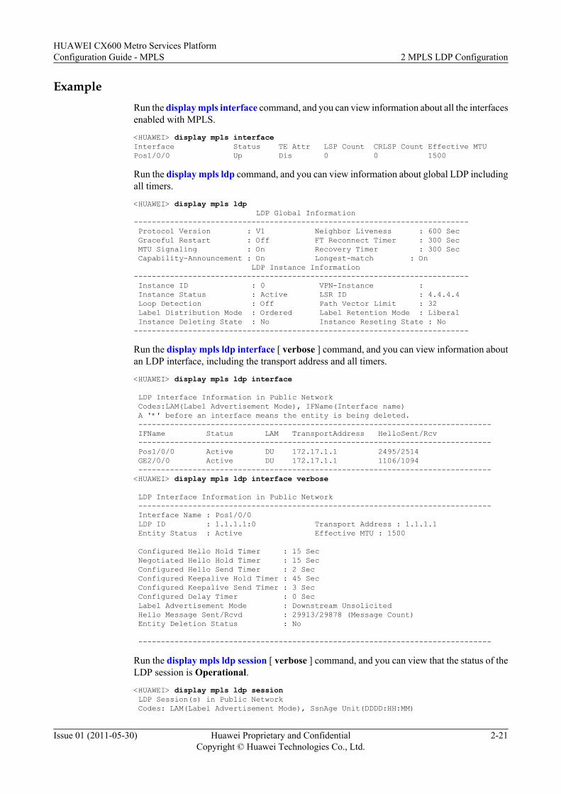
ExampleRun the display mpls interface command, and you can view information about all the interfacesenabled with MPLS.
<HUAWEI> display mpls interfaceInterface Status TE Attr LSP Count CRLSP Count Effective MTUPos1/0/0 Up Dis 0 0 1500
Run the display mpls ldp command, and you can view information about global LDP includingall timers.
<HUAWEI> display mpls ldp LDP Global Information-------------------------------------------------------------------------- Protocol Version : V1 Neighbor Liveness : 600 Sec Graceful Restart : Off FT Reconnect Timer : 300 Sec MTU Signaling : On Recovery Timer : 300 Sec Capability-Announcement : On Longest-match : On LDP Instance Information-------------------------------------------------------------------------- Instance ID : 0 VPN-Instance : Instance Status : Active LSR ID : 4.4.4.4 Loop Detection : Off Path Vector Limit : 32 Label Distribution Mode : Ordered Label Retention Mode : Liberal Instance Deleting State : No Instance Reseting State : No--------------------------------------------------------------------------
Run the display mpls ldp interface [ verbose ] command, and you can view information aboutan LDP interface, including the transport address and all timers.
<HUAWEI> display mpls ldp interface
LDP Interface Information in Public Network Codes:LAM(Label Advertisement Mode), IFName(Interface name) A '*' before an interface means the entity is being deleted. ------------------------------------------------------------------------------ IFName Status LAM TransportAddress HelloSent/Rcv ------------------------------------------------------------------------------ Pos1/0/0 Active DU 172.17.1.1 2495/2514 GE2/0/0 Active DU 172.17.1.1 1106/1094 ------------------------------------------------------------------------------<HUAWEI> display mpls ldp interface verbose
LDP Interface Information in Public Network ------------------------------------------------------------------------------ Interface Name : Pos1/0/0 LDP ID : 1.1.1.1:0 Transport Address : 1.1.1.1 Entity Status : Active Effective MTU : 1500
Configured Hello Hold Timer : 15 Sec Negotiated Hello Hold Timer : 15 Sec Configured Hello Send Timer : 2 Sec Configured Keepalive Hold Timer : 45 Sec Configured Keepalive Send Timer : 3 Sec Configured Delay Timer : 0 Sec Label Advertisement Mode : Downstream Unsolicited Hello Message Sent/Rcvd : 29913/29878 (Message Count) Entity Deletion Status : No
------------------------------------------------------------------------------
Run the display mpls ldp session [ verbose ] command, and you can view that the status of theLDP session is Operational.
<HUAWEI> display mpls ldp session LDP Session(s) in Public Network Codes: LAM(Label Advertisement Mode), SsnAge Unit(DDDD:HH:MM)
HUAWEI CX600 Metro Services PlatformConfiguration Guide - MPLS 2 MPLS LDP Configuration
Issue 01 (2011-05-30) Huawei Proprietary and ConfidentialCopyright © Huawei Technologies Co., Ltd.
2-21
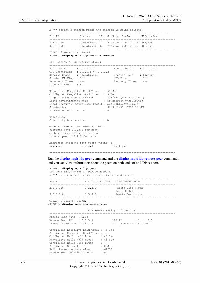
A '*' before a session means the session is being deleted. ------------------------------------------------------------------------------ PeerID Status LAM SsnRole SsnAge KASent/Rcv ------------------------------------------------------------------------------ 2.2.2.2:0 Operational DU Passive 0000:01:36 387/386 3.3.3.3:0 Operational DU Passive 0000:01:30 361/361 ------------------------------------------------------------------------------ TOTAL: 2 session(s) Found.<HUAWEI> display mpls ldp session verbose
LDP Session(s) in Public Network ------------------------------------------------------------------------------ Peer LDP ID : 2.2.2.2:0 Local LDP ID : 1.1.1.1:0 TCP Connection : 1.1.1.1 <- 2.2.2.2 Session State : Operational Session Role : Passive Session FT Flag : Off MD5 Flag : Off Reconnect Timer : --- Recovery Timer : --- Keychain Name : kc1
Negotiated Keepalive Hold Timer : 45 Sec Configured Keepalive Send Timer : 3 Sec Keepalive Message Sent/Rcvd : 438/438 (Message Count) Label Advertisement Mode : Downstream Unsolicited Label Resource Status(Peer/Local) : Available/Available Session Age : 0000:01:49 (DDDD:HH:MM) Session Deletion Status : No
Capability: Capability-Announcement : On
Outbound&Inbound Policies Applied : outbound peer 2.2.2.2 fec none outbound peer all split-horizon inbound peer 2.2.2.2 fec none
Addresses received from peer: (Count: 3) 10.1.1.2 2.2.2.2 10.1.2.1
------------------------------------------------------------------------------
Run the display mpls ldp peer command and the display mpls ldp remote-peer command,and you can view information about the peers on both ends of an LDP session.<HUAWEI> display mpls ldp peer LDP Peer Information in Public network A '*' before a peer means the peer is being deleted. ------------------------------------------------------------------------------ PeerID TransportAddress DiscoverySource ------------------------------------------------------------------------------ 2.2.2.2:0 2.2.2.2 Remote Peer : rtb Serial0/0/0 3.3.3.3:0 3.3.3.3 Remote Peer : rtc ------------------------------------------------------------------------------ TOTAL: 2 Peer(s) Found.<HUAWEI> display mpls ldp remote-peer
LDP Remote Entity Information ------------------------------------------------------------------------------ Remote Peer Name : lsrc Remote Peer IP : 3.3.3.9 LDP ID : 1.1.1.9:0 Transport Address : 1.1.1.9 Entity Status : Active
Configured Keepalive Hold Timer : 45 Sec Configured Keepalive Send Timer : --- Configured Hello Hold Timer : 45 Sec Negotiated Hello Hold Timer : 45 Sec Configured Hello Send Timer : --- Configured Delay Timer : 0 Sec Hello Packet sent/received : 61/59 Remote Peer Deletion Status : No
2 MPLS LDP ConfigurationHUAWEI CX600 Metro Services Platform
Configuration Guide - MPLS
2-22 Huawei Proprietary and ConfidentialCopyright © Huawei Technologies Co., Ltd.
Issue 01 (2011-05-30)
Auto-config : --- ------------------------------------------------------------------------------ TOTAL: 1 Peer(s) Found.
2.3 Configuring LDP LSPLDP is a label distribution protocol in an MPLS domain to distribute labels during the setup ofan LSP.
2.3.1 Establishing the Configuration TaskBefore configuring an LDP LSP, familiarize yourself with the applicable environment, completethe pre-configuration tasks, and obtain the required data. This can help you rapidly and correctlyfinish the configuration task.
2.3.2 Configuring LDP LSPAn LDP LSP can be set up only after an LDP session is set up.
2.3.3 (Optional) Configuring Label Advertisement ModesYou can control the establishment of an LSP by configuring an advertisement mode of LDPlabels.
2.3.4 (Optional) Configuring LDP to Automatically Trigger the Request in DoD ModeYou should configure a remote LDP session before configuring LDP Automatically Triggeringthe Request in DoD Mode
2.3.5 (Optional) Configuring Loop DetectionYou need to configure the LDP loop detection on each node to avoid loops.
2.3.6 (Optional) Configuring LDP MTU SignalingBy configuring the LDP MTU signaling, you can determine the size of MPLS packets to beforwarded according to an MTU.
2.3.7 (Optional) Configuring split horizonBy configuring an LDP split horizon policy, you can restrain an LSR from distributing labels tospecified downstream LDP peers.
2.3.8 (Optional) Configuring an Inbound LDP PolicyBy configuring an inbound LDP policy, you can prevent the establishment of unwanted LSPsby an LSR to save device memory.
2.3.9 (Optional) Configuring an Outbound LDP PolicyBy configuring an outbound LDP policy, you can prevent the establishment of unwanted LSPs,saving memory.
2.3.10 (Optional) Configuring the Policy of Triggering to Establish LSPsBy configuring the trigger policy of establishing LSPs, you can use eligible routes to triggerLDP to set up LSPs.
2.3.11 (Optional) Configuring the Policy of Establishing Transit LSPsBy configuring the trigger policy of establishing transit LSPs, you can use eligible routes totrigger LDP to set up transit LSPs.
2.3.12 Checking the ConfigurationAfter an LDP LSP is set up, you can view information about LDP, the establishment of LDPLSPs, and the establishment of LSPs.
HUAWEI CX600 Metro Services PlatformConfiguration Guide - MPLS 2 MPLS LDP Configuration
Issue 01 (2011-05-30) Huawei Proprietary and ConfidentialCopyright © Huawei Technologies Co., Ltd.
2-23
2.3.1 Establishing the Configuration TaskBefore configuring an LDP LSP, familiarize yourself with the applicable environment, completethe pre-configuration tasks, and obtain the required data. This can help you rapidly and correctlyfinish the configuration task.
Applicable EnvironmentIf you need not to strictly control the setup process of LSPs or deploy TE on an MPLS network,you can set up LSPs by using LDP as the label distribution protocol in an MPLS domain.
The number of LSPs that can be set up on an LSR depends on the capacity and performance ofthe LSR. Excessive LSPs, however, may lead to unstability of the LSR.
The setup of LSPs requires that proper routes exist on the LSRs and trigger policies be set onthe LSRs. Only routes that meet the trigger policy can trigger the setup of LSPs. In this manner,you can control the number of LSPs.
The CX600 provides the following types of policies for controlling the number of LSPs:
l The policies for setting up LSPs on the egress or ingress are as follows:– All static routes and IGP routes trigger the setup of LSPs.– Labeled BGP routes with 32-bit addresses of the public network trigger the setup of
LSPs. For more information, refer to the chapter "BGP/MPLS IP VPN Configuration"in the HUAWEI CX600 Metro Services Platform Configuration Guide - VPN.
– Host routes trigger the setup of LSPs.– The setup of LSPs is triggered on the basis of the IP prefix list.– All routes trigger the setup of LSPs with LDP being disabled.
l When an LSR is a transit LSR, the IP prefix list can be used to filter routes to prevent thegeneration of excessive transit LSPs. Only the routes that match the filtering policy can beused to set up the transit LSP.
As defined in RFC 5036, the label advertisement mode of LDP is classified into two modes:l Downstream Unsolicited (DU)l Downstream on Demand (DoD)
As defined in RFC 5036, the label distribution control mode of LDP is classified into two modes:l Independentl Ordered
As defined in RFC 5036, the label retention mode of LDP is classified into two modes:l Liberall Conservative
The CX600 recommends combination of DU mode + Ordered mode + Liberal mode.
To correctly implement path Maximum Transmission Unit (MTU) detection, an LSR needs toknow the MTU of each link to which the LSR is connected. Then, LDP MTU signaling isrequired.
Pre-configuration TasksBefore configuring an LDP LSP, complete the following task:
2 MPLS LDP ConfigurationHUAWEI CX600 Metro Services Platform
Configuration Guide - MPLS
2-24 Huawei Proprietary and ConfidentialCopyright © Huawei Technologies Co., Ltd.
Issue 01 (2011-05-30)
l Configure local LDP sessions
Data Preparation
To configure an LDP LSP, you need the following data.
No. Data
1 (Optional) Configuring Label Distribution and Retention Modes
2 (Optional) Maximum hops in loop detection
2.3.2 Configuring LDP LSPAn LDP LSP can be set up only after an LDP session is set up.
Prerequisite
Configuring LDP Sessions
Context
The MPLS LDP session is created on neighboring LSRs along the LSP. After the MPLS LDPsession is created, the LDP LSP starts to be set up automatically.
2.3.3 (Optional) Configuring Label Advertisement ModesYou can control the establishment of an LSP by configuring an advertisement mode of LDPlabels.
Context
Do as follows on LSR:
Procedure
Step 1 Run:system-view
The system view is displayed.
Step 2 Run:interface interface-type interface-number
The interface view is displayed.
Step 3 Run:mpls ldp advertisement { dod | du }
The label advertisement mode is configured.
HUAWEI CX600 Metro Services PlatformConfiguration Guide - MPLS 2 MPLS LDP Configuration
Issue 01 (2011-05-30) Huawei Proprietary and ConfidentialCopyright © Huawei Technologies Co., Ltd.
2-25
NOTE
l When there are multiple links between neighbors, all the interfaces must use the same labeladvertisement mode.
l Modifying the label advertisement mode causes LDP sessions to be reestablished.
----End
2.3.4 (Optional) Configuring LDP to Automatically Trigger theRequest in DoD Mode
You should configure a remote LDP session before configuring LDP Automatically Triggeringthe Request in DoD Mode
Context
On a large-scale network deployed with a large number of remote LDP peers, the DLSAMs thatare low-end devices at the edge of the network cannot ensure the network stability or preventresource wastes. In this case, you can run the remote-ip auto-dod-request command or theremote-peer auto-dod-request command to configure the function of triggering a request to adownstream node for a label mapping message associated with all remote LDP peers or a remoteLDP peer with a specified LSR ID in DoD mode, which can save system resources.
To disable the function of automatically triggering an LSR to send a request to a downstreamnode for a label mapping message associated with a specified LSR ID in DoD mode, you canrun the remote-ip auto-dod-request block command.
NOTE
l You should configure a remote LDP session before running the remote-peer auto-dod-request orremote-ip auto-dod-request command.
l You should run the longest-match command to configure LDP extension for inter-area LSP beforerunning the remote-peer auto-dod-request or remote-ip auto-dod-request command.
l The mpls ldp advertisement dod command should be run to create an LDP session with a downstreamnode in DoD mode before you run the remote-peer auto-dod-request or remote-ip auto-dod-request command.
Procedure
Step 1 Run:system-view
The system view is displayed.
Step 2 Run:mpls ldp
The MPLS LDP view is displayed.
Step 3 You can perform either of the following procedures to enable the function of triggering a requestto a downstream node for a label mapping message associated with all remote LDP peers or aremote LDP peer with a specified LSR ID in DoD mode.l To enable the function of triggering a request to a downstream node for label mapping
messages associated with all remote LDP peers in DoD mode, run:remote-peer auto-dod-request
2 MPLS LDP ConfigurationHUAWEI CX600 Metro Services Platform
Configuration Guide - MPLS
2-26 Huawei Proprietary and ConfidentialCopyright © Huawei Technologies Co., Ltd.
Issue 01 (2011-05-30)
l You can perform the following procedures to enable the function of triggering a request toa downstream node for label mapping messages associated with all remote LDP peers or aremote LDP peer with a specified LSR ID in DoD mode.
1. Run:quit
The system view is displayed.2. Run:
mpls ldp remote-peer remote-peer-name
The remote MPLS LDP peer is created and the remote MPLS LDP peer view isdisplayed.
3. Run:remote-ip ip-addressThe IP address of the remote MPLS LDP peer is configured.
NOTE
l The IP address of the remote LDP peer must be the LSR ID of the remote LDP peer. Whenan LDP LSR ID is different from an MPLS LSR ID, the LDP LSR ID must be adopted.
l Modifying or deleting the configured address of a remote peer leads to the deletion of theremote LDP session.
4. Run:remote-ip auto-dod-requestThe function of automatically triggering a request to a downstream node for a labelmapping message associated with a remote LDP peer of a specified LSR ID in DoDmode is configured.
NOTEAfter the remote-peer auto-dod-request command have been configured globally, to disablethe function of automatically triggering an LSR to send a request to a downstream node for alabel mapping message associated with a remote LDP peer of a specified LSR ID in DoD mode,you can run the remote-ip auto-dod-request block command.
----End
2.3.5 (Optional) Configuring Loop DetectionYou need to configure the LDP loop detection on each node to avoid loops.
ContextThe CX600 does not support loop detection. However, in the scenario where its neighborsupports the loop detection function and requires that the notification about whether the loopdetection function be consistent on the two ends, to ensure that the CX600 sets up an LDP sessionwith such a neighbor, do as follows:
Procedure
Step 1 Run:system-view
The system view is displayed.
Step 2 Run:mpls ldp
HUAWEI CX600 Metro Services PlatformConfiguration Guide - MPLS 2 MPLS LDP Configuration
Issue 01 (2011-05-30) Huawei Proprietary and ConfidentialCopyright © Huawei Technologies Co., Ltd.
2-27
The MPLS LDP view is displayed.
Step 3 Run:loop-detect
The device is enabled to advertise that the device has the capable of loop detection during theinitialization of an LDP session.
NOTEAfter the device is configured with the loop-detect command, the device still does not support the loopdetection function but only has the loop detection negotiation capability.
----End
2.3.6 (Optional) Configuring LDP MTU SignalingBy configuring the LDP MTU signaling, you can determine the size of MPLS packets to beforwarded according to an MTU.
Context
LDP automatically computes the minimum MTU value of all interfaces on each LSP. Based onthe minimum MTU value, MPLS determines the size of packets to be forwarded on the ingress.This prevents the forwarding failure that is caused by large packets on the transit.
Do as follows on each LSR along an LSP:
Procedure
Step 1 Run:system-view
The system view is displayed.
Step 2 Run:mpls ldp
The MPLS LDP view is displayed.
Step 3 Run:mtu-signalling [ apply-tlv ]
The system is enabled to send the MTU TLV.
By default, the system sends the private MTU TLV.
NOTE
Enabling or disabling the sending of the MTU TLV may cause the original LDP session to be re-created.
----End
2.3.7 (Optional) Configuring split horizonBy configuring an LDP split horizon policy, you can restrain an LSR from distributing labels tospecified downstream LDP peers.
2 MPLS LDP ConfigurationHUAWEI CX600 Metro Services Platform
Configuration Guide - MPLS
2-28 Huawei Proprietary and ConfidentialCopyright © Huawei Technologies Co., Ltd.
Issue 01 (2011-05-30)
ContextBy default, an LSR allocates labels to both upstream and downstream devices, which speeds upthe convergence of the LDP LSP. In the networking where the DSLAM is deployed, to savememory, it is recommended to configure the outbound peer { peer-id | all } split-horizoncommand on LSRs to enable split horizon. After that, the LSRs allocate labels only to theirupstream LDP peers.
Procedure
Step 1 Run:system-view
The system view is displayed.
Step 2 Run:mpls ldp
The MPLS LDP view is displayed.
Step 3 Run:outbound peer { peer-id | all } split-horizon
The split horizon is enabled on the LSR, that is, the LSR allocates labels only to its upstreamLDP peers.
By default, split horizon is disabled on the LDP peer, that is, an LSR allocates labels to bothupstream and downstream devices.
----End
2.3.8 (Optional) Configuring an Inbound LDP PolicyBy configuring an inbound LDP policy, you can prevent the establishment of unwanted LSPsby an LSR to save device memory.
ContextBy default, an LSR receives all label mapping messages, speeding up the convergence of LDPLSPs. This, however, results in the establishment of a large number of LSPs, wasting resources.In this case, an inbound LDP policy can be configured to reduce the number of label mappingmessages to be received, reducing the number of LSPs to be established and saving memory.
NOTE
To delete all inbound policies at a time, run the undo inbound peer all command.
Procedure
Step 1 Run:system-view
The system view is displayed.
Step 2 Run:mpls ldp
HUAWEI CX600 Metro Services PlatformConfiguration Guide - MPLS 2 MPLS LDP Configuration
Issue 01 (2011-05-30) Huawei Proprietary and ConfidentialCopyright © Huawei Technologies Co., Ltd.
2-29
MLS LDP view is displayed.
Step 3 Run:inbound peer { peer-id | peer-group peer-group-name | all } fec { none | host | ip-prefix prefix-name }
An inbound policy for allowing a specified LDP peer to receive label mapping messages for aspecified IGP route is configured.
To apply a policy associated with the same FEC range to an LDP peer group or all LDP peersreceiving label mapping messages, configure peer-group peer-group-name or all in thecommand.
NOTE
If multiple inbound policies coexist, the first configured inbound policy takes effect on a certain peer.Between the following inbound policies, as the peer group named group1 includes the peer with the IDbeing 2.2.2.2, the first inbound policy which is configured earlier takes effect on peer 2.2.2.2.inbound peer 2.2.2.2 fec hostinbound peer peer-group group1 fec noneIf two inbound policies have been configured with the same peer parameters, the latter overwrites theearlier. Between the following inbound policies, the latter overwrites the earlier configuration. That is, thesecond inbound policy which is configured later takes effect on peer 2.2.2.2.inbound peer 2.2.2.2 fec hostinbound peer 2.2.2.2 fec noneBefore configuring an inbound policy, you must enable MPLS and MPLS LDP globally.
----End
2.3.9 (Optional) Configuring an Outbound LDP PolicyBy configuring an outbound LDP policy, you can prevent the establishment of unwanted LSPs,saving memory.
Context
By default, an LSR sends label mapping messages to both upstream and downstream LDP peers,speeding up the convergence of LDP LSPs. This, however, results in the establishment of a largenumber of LSPs, wasting resources. In this case, an outbound LDP policy needs to be configuredto reduce the number of label mapping messages to be sent, reducing the number of LDP LSPsto be established and saving memory.
NOTE
If multiple outbound policies coexist, the first configured outbound policy takes effect on a certain peer.Between the following outbound policies, as the peer group named group1 includes the peer with the IDbeing 2.2.2.2, the first outbound policy which is configured earlier takes effect on peer 2.2.2.2.outbound peer 2.2.2.2 fec hostoutbound peer peer-group group1 fec noneIf two outbound policies have been configured with the same peer parameters, the latter overwrites theearlier. Between the following outbound policies, the latter overwrites the earlier configuration. That is,the second outbound policy which is configured later takes effect on peer 2.2.2.2.outbound peer 2.2.2.2 fec hostoutbound peer 2.2.2.2 fec noneBefore configuring an outbound policy, you must enable MPLS and MPLS LDP globally.
To delete all outbound policies at a time, run the undo outbound peer all command.
2 MPLS LDP ConfigurationHUAWEI CX600 Metro Services Platform
Configuration Guide - MPLS
2-30 Huawei Proprietary and ConfidentialCopyright © Huawei Technologies Co., Ltd.
Issue 01 (2011-05-30)
Procedurel Configure a split horizon policy.
1. Run:system-view
The system view is displayed.2. Run:
mpls ldp
The MPLS LDP view is displayed.3. Run:
outbound peer { peer-id | all } split-horizon
A split horizon policy is configured to restrain an LSR from distributing labels to aspecified LDP peer.
By default, no split horizon policy is configured, which allows an LSR to distributelabels to all LDP peers.
l Configure an outbound policy for allowing label mapping messages for a specified IGProute to be sent to a specified LDP peer.1. Run:
system-view
The system view is displayed.2. Run:
mpls ldp
MPLS LDP view is displayed.3. Run:
outbound peer { peer-id | peer-group peer-group-name | all } fec { none | host | ip-prefix prefix-name }
An outbound policy is configured to allow label mapping messages for a specifiedIGP route to be sent to a specified LDP peer.
To apply the policy associated with the same FEC range to an LDP peer group or allLDP peers sending label mapping messages, you can configure peer-group peer-group-name or all in the command.
l Configure an outbound policy for allowing label mapping messages for a specified labeledBGP route to be sent to a specified LDP peer.1. Run:
system-view
The system view is displayed.2. Run:
mpls ldp
MPLS LDP view is displayed.3. Run:
outbound peer { peer-id | peer-group peer-group-name | all } bgp-label-route { none | ip-prefix prefix-name }
An outbound policy is configured to allow label mapping messages for a specifiedlabeled BGP route to be sent to a specified LDP peer.
HUAWEI CX600 Metro Services PlatformConfiguration Guide - MPLS 2 MPLS LDP Configuration
Issue 01 (2011-05-30) Huawei Proprietary and ConfidentialCopyright © Huawei Technologies Co., Ltd.
2-31
To apply the policy associated with the same FEC range to an LDP peer group or allLDP peers sending label mapping messages, you can configure either peer-grouppeer-group-name or all in the command.
----End
2.3.10 (Optional) Configuring the Policy of Triggering to EstablishLSPs
By configuring the trigger policy of establishing LSPs, you can use eligible routes to triggerLDP to set up LSPs.
ContextTo set up an LSP according to LDP, you need to set the FEC.
NOTE
l The establishment of an LSP requires precisely matched routes on the LSR. If a loopback interfacewith a 32-bit mask is used, the precisely matched host route is required to trigger the establishment ofLSPs.
l Changing LSP triggering policies during the LDP graceful restart (GR) does not take effect.
Do as follows on all the LSRs along the LSP:
ProcedureStep 1 Run:
system-view
The system view is displayed.
Step 2 Run:mpls
The MPLS view is displayed.
Step 3 Run the following commands as required.l To configure the policy of triggering static routes and IGP routes to establish LSPs, run:
lsp-trigger { all | host | ip-prefix ip-prefix-name | none }l To configure the policy of triggering labeled BGP routes of the public network to establish
LSPs, run:lsp-trigger bgp-label-route
By default, the triggering policy is host, namely, the route of host IP with the 32-bit addresstriggering to establish an LSP.
l If the triggering policy is all, all static route entries and IGP route entries trigger to establishan LSP. BGP public routes cannot trigger to establish LSPs.
l If the triggering policy is ip-prefix, only the FEC entry filtered in the IP address prefix listcan trigger to establish an LSP.
l If the triggering policy is none, the LSP is not established.l If the triggering policy is bgp-label-route, the labeled BGP routes of the public network
trigger to establish an LSP.
----End
2 MPLS LDP ConfigurationHUAWEI CX600 Metro Services Platform
Configuration Guide - MPLS
2-32 Huawei Proprietary and ConfidentialCopyright © Huawei Technologies Co., Ltd.
Issue 01 (2011-05-30)
2.3.11 (Optional) Configuring the Policy of Establishing TransitLSPs
By configuring the trigger policy of establishing transit LSPs, you can use eligible routes totrigger LDP to set up transit LSPs.
ContextDo as follows on the transit node:
Procedure
Step 1 Run:system-view
The system view is displayed.
Step 2 Run:mpls ldp
The MPLS LDP view is displayed.
Step 3 Run:propagate mapping for ip-prefix ip-prefix-name
The policy of establishing transit LSPs is configured.
By default, LDP does not filter the received routing information while establishing transit LSPs.
NOTE
Modifying the policy for setting up transit LSPs does not take effect during LDP GR.
----End
2.3.12 Checking the ConfigurationAfter an LDP LSP is set up, you can view information about LDP, the establishment of LDPLSPs, and the establishment of LSPs.
PrerequisiteThe configurations of the LDP LSP function are complete.
Procedurel Run the display mpls ldp [ all ] [ verbose ] command to check all information about LDP.l Run the display mpls ldp lsp [ all ] command to check information of all LDP LSPs.l Run the display mpls lsp [ verbose ] command to check information about LSPs.
----End
ExampleIf the configurations succeed, you can view the following information:
HUAWEI CX600 Metro Services PlatformConfiguration Guide - MPLS 2 MPLS LDP Configuration
Issue 01 (2011-05-30) Huawei Proprietary and ConfidentialCopyright © Huawei Technologies Co., Ltd.
2-33
Run the display mpls ldp command, and you can view information about global LDP includingall timers.
<HUAWEI> display mpls ldp
LDP Global Information-------------------------------------------------------------------------- Protocol Version : V1 Neighbor Liveness : 600 Sec Graceful Restart : Off FT Reconnect Timer : 300 Sec MTU Signaling : On Recovery Timer : 300 Sec Capability-Announcement : Off Longest-match : Off LDP Instance Information-------------------------------------------------------------------------- Instance ID : 0 VPN-Instance : Instance Status : Active LSR ID : 4.4.4.4 Loop Detection : Off Path Vector Limit : 32 Label Distribution Mode : Ordered Label Retention Mode : Liberal Instance Deleting State : No Instance Reseting State : No --------------------------------------------------------------------------
Run the display mpls ldp lsp or the display mpls lsp command, and you can view informationabout LDP LSPs.
<HUAWEI> display mpls ldp lsp
LDP LSP Information ------------------------------------------------------------------------------- DestAddress/Mask In/OutLabel UpstreamPeer NextHop OutInterface ------------------------------------------------------------------------------- 3.3.3.9/32 NULL/1025 - 10.1.1.2 Pos1/0/0 ------------------------------------------------------------------------------- TOTAL: 1 Normal LSP(s) Found. TOTAL: 0 Liberal LSP(s) Found. TOTAL: 0 Frr LSP(s) Found. A '*' before an LSP means the LSP is not established A '*' before a Label means the USCB or DSCB is stale A '*' before a UpstreamPeer means the session is in GR state A '*' before a NextHop means the LSP is FRR LSP<HUAWEI> display mpls lsp---------------------------------------------------------------------- LSP Information: LDP LSP----------------------------------------------------------------------FEC In/Out Label In/Out IF Vrf Name1.1.1.1/32 NULL/3 -/Pos1/0/0
2.4 Configuring LDP Extension for Inter-Area LSPConfiguring LDP Extension for Inter-Area LSP enables LDP to search for routes according tothe longest match rule to establish inter-area LDP LSPs.
2.4.1 Establishing the Configuration TaskBefore configuring the LDP extension for Inter-Area LSP, familiarize yourself with theapplicable environment, complete the pre-configuration tasks, and obtain the required data. Thiscan help you rapidly and correctly finish the configuration task.
2.4.2 Configuring LDP Extension for Inter-Area LSPTo configure LDP extension for Inter-Area LSP, you need to configure the ingress or transitnode.
2.4.3 Checking the ConfigurationAfter the LDP extension for Inter-Area LSP is configured, you can view information about theestablishment of Inter-Area LSPs.
2 MPLS LDP ConfigurationHUAWEI CX600 Metro Services Platform
Configuration Guide - MPLS
2-34 Huawei Proprietary and ConfidentialCopyright © Huawei Technologies Co., Ltd.
Issue 01 (2011-05-30)
2.4.1 Establishing the Configuration TaskBefore configuring the LDP extension for Inter-Area LSP, familiarize yourself with theapplicable environment, complete the pre-configuration tasks, and obtain the required data. Thiscan help you rapidly and correctly finish the configuration task.
Applicable EnvironmentIn a large-scale network, multiple IGP areas usually need to be configured for flexible networkdeployment and fast route convergence. In this situation, when advertising routes between IGPareas, to prevent a large number of routes from consuming too many resources, an Area BorderRouter (ABR) needs to aggregate the routes in the area and then advertises the aggregated routeto the neighbor IGP areas. However, by default, when establishing LSPs, LDP searches therouting table for the route that exactly matches the forwarding equivalence class (FEC) carriedin the received Label Mapping message. For aggregated routes, only liberal LDP LSPs ratherthan inter-area LDP LSPs can be set up.
In this case, you can run the longest-match command to configure LDP to search for routesaccording to the longest match rule to establish inter-area LDP LSPs.
Pre-configuration TasksBefore configuring LDP Extension for Inter-Area LSP, complete the following tasks:
l Configuring IP addresses for interfaces to make neighboring nodes reachable at the networklayer
l Configuring an IGP to advertise the network segments connecting to interfaces on eachnode and to advertise the routes of hosts with LSR IDs
l Configure the policy for aggregating routes.l Configuring MPLS and MPLS LDP
Data PreparationTo configure LDP Extension for Inter-Area LSP, you need the following data.
No. Data
1 IS-IS area ID of each nodes and levels of each nodes and interfaces
2.4.2 Configuring LDP Extension for Inter-Area LSPTo configure LDP extension for Inter-Area LSP, you need to configure the ingress or transitnode.
Procedure
Step 1 Run:system-view
The system view is displayed.
HUAWEI CX600 Metro Services PlatformConfiguration Guide - MPLS 2 MPLS LDP Configuration
Issue 01 (2011-05-30) Huawei Proprietary and ConfidentialCopyright © Huawei Technologies Co., Ltd.
2-35
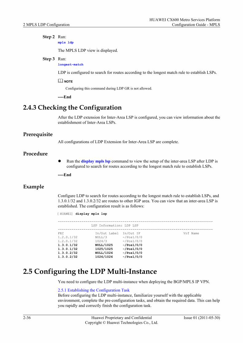
Step 2 Run:mpls ldp
The MPLS LDP view is displayed.
Step 3 Run:longest-match
LDP is configured to search for routes according to the longest match rule to establish LSPs.
NOTE
Configuring this command during LDP GR is not allowed.
----End
2.4.3 Checking the ConfigurationAfter the LDP extension for Inter-Area LSP is configured, you can view information about theestablishment of Inter-Area LSPs.
PrerequisiteAll configurations of LDP Extension for Inter-Area LSP are complete.
Procedurel Run the display mpls lsp command to view the setup of the inter-area LSP after LDP is
configured to search for routes according to the longest match rule to establish LSPs.
----End
ExampleConfigure LDP to search for routes according to the longest match rule to establish LSPs, and1.3.0.1/32 and 1.3.0.2/32 are routes to other IGP area. You can view that an inter-area LSP isestablished. The configuration result is as follows:
[HUAWEI] display mpls lsp
------------------------------------------------------------------------------- LSP Information: LDP LSP-------------------------------------------------------------------------------FEC In/Out Label In/Out IF Vrf Name1.2.0.1/32 NULL/3 -/Pos1/0/01.2.0.1/32 1024/3 -/Pos1/0/01.3.0.1/32 NULL/1025 -/Pos1/0/01.3.0.1/32 1025/1025 -/Pos1/0/01.3.0.2/32 NULL/1026 -/Pos1/0/01.3.0.2/32 1026/1026 -/Pos1/0/0
2.5 Configuring the LDP Multi-InstanceYou need to configure the LDP multi-instance when deploying the BGP/MPLS IP VPN.
2.5.1 Establishing the Configuration TaskBefore configuring the LDP multi-instance, familiarize yourself with the applicableenvironment, complete the pre-configuration tasks, and obtain the required data. This can helpyou rapidly and correctly finish the configuration task.
2 MPLS LDP ConfigurationHUAWEI CX600 Metro Services Platform
Configuration Guide - MPLS
2-36 Huawei Proprietary and ConfidentialCopyright © Huawei Technologies Co., Ltd.
Issue 01 (2011-05-30)
2.5.2 Configuring the LDP Multi-InstanceTo configure the LDP multi-instance, you need to enable LDP for the specified VPN instanceon each node.
2.5.3 Checking the ConfigurationAfter the LDP multi-instance is configured, you can view information about LDP of the specifiedVPN instance.
2.5.1 Establishing the Configuration TaskBefore configuring the LDP multi-instance, familiarize yourself with the applicableenvironment, complete the pre-configuration tasks, and obtain the required data. This can helpyou rapidly and correctly finish the configuration task.
Applicable Environment
The LDP multi-instance is used on the BGP/MPLS VPN. To configure the LDP multi-instance,you need to bind LDP to a created IP VPN instance.
Pre-configuration Tasks
Before configuring an LDP multi-instance, complete the following tasks:
l Enabling MPLS
l Enabling MPLS LDP
l Configuring the IP VPN instance
Data Preparation
To configure an LDP multi-instance, you need the following data.
No. Data
1 LSR ID of each node
2 Name of the interface that forwards MPLS packets
3 Name of the VPN instance to be enabled with LDP
4 LSR ID of the LDP instance
2.5.2 Configuring the LDP Multi-InstanceTo configure the LDP multi-instance, you need to enable LDP for the specified VPN instanceon each node.
Context
To configure the transport address for an LDP instance, you must use the IP address of theinterfaces that are bound to the same VPN instance.
HUAWEI CX600 Metro Services PlatformConfiguration Guide - MPLS 2 MPLS LDP Configuration
Issue 01 (2011-05-30) Huawei Proprietary and ConfidentialCopyright © Huawei Technologies Co., Ltd.
2-37

NOTE
In LDP multiple instances, you can adopt the interface address to establish a session.
Do as follows on each LSR in an MPLS domain:
Procedure
Step 1 Run:system-view
The system view is displayed.
Step 2 Run:mpls ldp vpn-instance vpn-instance-name
LDP for the specified VPN instance is enabled and the MPLS LDP VPN instance view isdisplayed.
Note:
l Configurations in the MPLS LDP VPN instance view have impact only on LDP-enabledinterfaces that are bound to the same VPN instance.
l Configurations in the MPLS LDP view have no impact on LDP-enabled interfaces that arebound to the VPN instance.
Step 3 (Optional) Run:lsr-id lsr-id
An LSR ID is configured for the LDP VPN instance.
By default, the LDP LSR ID is MPLS LSR ID.
NOTE
In most applications, you need not change the default LDP LSR ID. In some networking schemes that VPNinstances are used, for example, BGP or MPLS VPN, configure an LSR ID separately for LDP multi-instance to ensure normal establishment of the TCP connection, if the address space of the VPN overlapsthat of the public network.
----End
2.5.3 Checking the ConfigurationAfter the LDP multi-instance is configured, you can view information about LDP of the specifiedVPN instance.
PrerequisiteThe configurations of the LDP Multi-Instance function are complete.
Procedurel Run the display mpls ldp vpn-instance vpn-instance-name command to check information
about LDP of a specified VPN instance.
----End
2 MPLS LDP ConfigurationHUAWEI CX600 Metro Services Platform
Configuration Guide - MPLS
2-38 Huawei Proprietary and ConfidentialCopyright © Huawei Technologies Co., Ltd.
Issue 01 (2011-05-30)
ExampleAfter the configuration, run the preceding command, and you can view information about thespecified LDP VPN instance.
2.6 Configuring Static BFD for LDP LSPBy configuring a static BFD session to detect an LDP LSP, you can detect LSP connectivityaccording to specified parameters.
2.6.1 Establishing the Configuration TaskBefore configuring a static BFD session to detect an LDP LSP, familiarize yourself with theapplicable environment, complete the pre-configuration tasks, and obtain the required data. Thiscan help you rapidly and correctly finish the configuration task.
2.6.2 Enabling Global BFD CapabilityYou need to only enable BFD on both ends of the link to be detected.
2.6.3 Configuring BFD with Specific Parameters on IngressYou need to configure BFD parameters on the ingress node before configuring a static BFDsession to detect an LDP LSP.
2.6.4 Configuring BFD with Specific Parameters on EgressYou need to configure BFD parameters on the egress node before configuring a static BFDsession to detect an LDP LSP.
2.6.5 Checking the ConfigurationAfter the configuration of detecting an LDP LSP through a static BFD session, you can viewthe BFD configuration, the specified BFD session, and BFD statistics.
2.6.1 Establishing the Configuration TaskBefore configuring a static BFD session to detect an LDP LSP, familiarize yourself with theapplicable environment, complete the pre-configuration tasks, and obtain the required data. Thiscan help you rapidly and correctly finish the configuration task.
Applicable EnvironmentWhen the static BFD works in an LDP LSP, note that:
l BFD can be bound only on the ingress of LDP LSP.l One LSP can be bound to only one BFD session.l The detection only supports the LDP LSP that is triggered to establish by the host route.
NOTE
BFD for LSP can function properly though the forward path is an LSP and the backward path is an IP link.The forward path and the backward path must be established over the same link; otherwise, if a fault occurs,BFD cannot identify the faulty path. Before deploying BFD, ensure that the forward and backward pathsare over the same link so that BFD can correctly identify the faulty path.
Pre-configuration TasksBefore configuring the static BFD for LDP LSP, complete the following tasks:
l Configuring parameters of the network layer to make the network accessible
HUAWEI CX600 Metro Services PlatformConfiguration Guide - MPLS 2 MPLS LDP Configuration
Issue 01 (2011-05-30) Huawei Proprietary and ConfidentialCopyright © Huawei Technologies Co., Ltd.
2-39
l Enabling MPLS LDPs on all nodes and establishing an LDP sessionl Configuring an LDP LSP
Data PreparationsBefore configuring the static BFD for LDP LSP, you need the following data.
No. Data
1 BFD configuration name
2 LDP LSP parameters:l Next hop address of an LSPl (Optional) Type and number of interfaces
3 Local discriminator and remote discriminator of a BFD session
2.6.2 Enabling Global BFD CapabilityYou need to only enable BFD on both ends of the link to be detected.
ContextDo as follows on each LSR on both ends of a link that to be detected:
Procedure
Step 1 Run:system-view
The system view is displayed.
Step 2 Run:bfd
This node is enabled with the global BFD function. The BFD global view is displayed.
----End
2.6.3 Configuring BFD with Specific Parameters on IngressYou need to configure BFD parameters on the ingress node before configuring a static BFDsession to detect an LDP LSP.
ContextDo as follows on the ingress of an LSP:
Procedure
Step 1 Run:system-view
2 MPLS LDP ConfigurationHUAWEI CX600 Metro Services Platform
Configuration Guide - MPLS
2-40 Huawei Proprietary and ConfidentialCopyright © Huawei Technologies Co., Ltd.
Issue 01 (2011-05-30)
The system view is displayed.
Step 2 Run:bfd cfg-name bind ldp-lsp peer-ip ip-address nexthop ip-address [ interface interface-type interface-number ]
The BFD session is bound to a dynamic LSP.
When the IP address of the egress on the LSP to be detected is borrowed or lent, an interfacemust be specified.
Step 3 Configure the discriminators.l Run:
discriminator local discr-valueThe local discriminator is configured.
l Or, run:discriminator remote discr-valueThe remote discriminator is configured.
NOTE
The local identifier and remote identifier on both ends of a BFD session must accord with each other.Otherwise, the session cannot be established correctly. In addition, the local identifier and remote identifiercannot be modified after configuration.
Step 4 (Optional) Run the following commands to adjust the minimum interval for the local device tosend BFD packets, the minimum interval for receiving BFD packets and the local BFD detectionmultiple:1. Run the quit command to return to the system view.2. Run the mpls command to globally enable MPLS and the enter the MPLS view.3. Run the mpls bfd min-tx-interval interval command to adjust the minimum interval for
the local device to send BFD packets.
The minimum interval for the local device to send BFD packets is set.
By default, the value is 1000 milliseconds.
If the backward link is an IP link, this parameter is not applicable.
Actual interval for the local device to send BFD packets = MAX { Locally configuredinterval for sending BFD packets, Remotely configured interval for receiving BFDpackets}; Actual interval for the local to receive BFD packets = MAX {Remotelyconfigured interval for sending BFD packets, Locally configured interval for receivingBFD packets}; Local detection period = Actual interval for the local device to Receive BFDpackets x Remotely configured BFD detection multiple.
For example, assume that the values of parameters are as follows:
l On the local device, the interval for sending BFD packets is set to 200 ms, the intervalfor receiving BFD packets is set to 300 ms, and the detection multiple is set to 4.
l On the peer device, the interval for sending BFD packets is 100 ms, the interval forreceiving BFD packets is 600 ms, and the detection multiple is 5.
Then,
l On the local device, the actual interval for sending BFD packets is 600 ms calculatedby using the formula max {200 ms, 600 ms}, the interval for receiving BFD packets is
HUAWEI CX600 Metro Services PlatformConfiguration Guide - MPLS 2 MPLS LDP Configuration
Issue 01 (2011-05-30) Huawei Proprietary and ConfidentialCopyright © Huawei Technologies Co., Ltd.
2-41
300 ms calculated by using the formula max {100 ms, 300 ms}, and the detection periodis 1500 ms calculated by 300 ms multiplied by 5.
l On the peer device, the actual interval for sending local BFD packets is 300 ms obtainedby using the formula max {100 ms, 300 ms}, the interval for receiving BFD packets is600 ms obtained by using the formula max {200 ms, 600 ms}, and the detection periodis 2400 ms obtained by 600 ms multiplied by 4.
4. Run the mpls bfd min-rx-interval interval command to adjust the minimum interval forreceiving BFD packets.
The minimum interval for receiving BFD packets is adjusted on the local device.
By default, the value is 1000 milliseconds.
If the backward link is an IP link, this parameter is not applicable.5. Run the mpls bfd detect-multiplier multiplier command to adjust the local BFD detection
multiple.
The default value is 3.6. Run the quit command to return to the system view.7. Run the bfd cfg-name command to enter the BFD session view.
Step 5 Run:process-pst
The BFD session status changes can be advertised to the application on the upper layer.
Step 6 Run:commit
The configuration is committed.
----End
Follow-up ProcedureWhen the BFD session is established and its status is Up, the BFD starts to detect failure in anLDP LSP.
When the LDP LSP is deleted, the BFD status turns Down.
The system does not delete BFD configuration entries and session entries until the LDP sessionis deleted.
2.6.4 Configuring BFD with Specific Parameters on EgressYou need to configure BFD parameters on the egress node before configuring a static BFDsession to detect an LDP LSP.
ContextThe IP link, LSP, or TE tunnel can be used as the reverse tunnel to inform the ingress of a fault.To avoid affecting BFD detection, an IP link is preferentially selected to inform the ingress ofan LSP fault. The process-pst command is prohibited when a reverse tunnel is configured. Ifthe configured reverse tunnel requires BFD detection, you can configure a pair of BFD sessionsfor it.
2 MPLS LDP ConfigurationHUAWEI CX600 Metro Services Platform
Configuration Guide - MPLS
2-42 Huawei Proprietary and ConfidentialCopyright © Huawei Technologies Co., Ltd.
Issue 01 (2011-05-30)
Do as follows on the egress of the LSP:
ProcedureStep 1 Run:
system-view
The system view is displayed.
Step 2 Configure BFD session:l For the IP link, run:
bfd cfg-name bind peer-ip peer-ip [ vpn-instance vpn-instance-name ] [ interface interface-type interface-number ] [ source-ip source-ip ]
l For the dynamic LSP, run:bfd cfg-name bind ldp-lsp peer-ip ip-address nexthop ip-address [ interface interface-type interface-number ]
l For the static LSP, run:bfd cfg-name bind static-lsp lsp-name
l For MPLS TE, run:bfd cfg-name bind mpls-te interface tunnel tunnel-number [ te-lsp ]
Step 3 Configure the discriminators.l Run:
discriminator local discr-valueThe local discriminator is configured.
l Run:discriminator remote discr-valueThe remote discriminator is configured.NOTE
The local identifier and remote identifier on both ends of a BFD session must accord with each other. Thesession cannot be established correctly otherwise. In addition, the local identifier and remote identifiercannot be modified after configuration.
Step 4 (Optional) Run the following commands to adjust the minimum interval for the local device tosend BFD packets, the minimum interval for receiving BFD packets and the local BFD detectionmultiple:1. Run the quit command to return to the system view.2. Run the mpls command to globally enable MPLS and the enter the MPLS view.3. Run the mpls bfd min-tx-interval interval command to adjust the minimum interval for
the local device to send BFD packets.
The minimum interval for the local device to send BFD packets is set.
By default, the value is 1000 milliseconds.
If the backward link is an IP link, this parameter is not applicable.
Actual interval for the local device to send BFD packets = MAX { Locally configuredinterval for sending BFD packets, Remotely configured interval for receiving BFDpackets}; Actual interval for the local to receive BFD packets = MAX {Remotelyconfigured interval for sending BFD packets, Locally configured interval for receivingBFD packets}; Local detection period = Actual interval for the local device to Receive BFDpackets x Remotely configured BFD detection multiple.
HUAWEI CX600 Metro Services PlatformConfiguration Guide - MPLS 2 MPLS LDP Configuration
Issue 01 (2011-05-30) Huawei Proprietary and ConfidentialCopyright © Huawei Technologies Co., Ltd.
2-43
For example, assume that the values of parameters are as follows:
l On the local device, the interval for sending BFD packets is set to 200 ms, the intervalfor receiving BFD packets is set to 300 ms, and the detection multiple is set to 4.
l On the peer device, the interval for sending BFD packets is 100 ms, the interval forreceiving BFD packets is 600 ms, and the detection multiple is 5.
Then,
l On the local device, the actual interval for sending BFD packets is 600 ms calculatedby using the formula max {200 ms, 600 ms}, the interval for receiving BFD packets is300 ms calculated by using the formula max {100 ms, 300 ms}, and the detection periodis 1500 ms calculated by 300 ms multiplied by 5.
l On the peer device, the actual interval for sending local BFD packets is 300 ms obtainedby using the formula max {100 ms, 300 ms}, the interval for receiving BFD packets is600 ms obtained by using the formula max {200 ms, 600 ms}, and the detection periodis 2400 ms obtained by 600 ms multiplied by 4.
4. Run the mpls bfd min-rx-interval interval command to adjust the minimum interval forreceiving BFD packets.
The minimum interval for receiving BFD packets is adjusted on the local device.
By default, the value is 1000 milliseconds.
If the backward link is an IP link, this parameter is not applicable.5. Run the mpls bfd detect-multiplier multiplier command to adjust the local BFD detection
multiple.
The default value is 3.6. Run the quit command to return to the system view.7. Run the bfd cfg-name command to enter the BFD session view.
Step 5 Run:commit
The configuration is committed.
----End
2.6.5 Checking the ConfigurationAfter the configuration of detecting an LDP LSP through a static BFD session, you can viewthe BFD configuration, the specified BFD session, and BFD statistics.
PrerequisiteThe configurations of the static BFD for LDP LSP function are complete.
Procedurel Run the display bfd configuration { all | static } [ for-lsp ] command to check the BFD
configuration.l Run the display bfd session { all | static } [ for-lsp ] command to check information about
the BFD session.
2 MPLS LDP ConfigurationHUAWEI CX600 Metro Services Platform
Configuration Guide - MPLS
2-44 Huawei Proprietary and ConfidentialCopyright © Huawei Technologies Co., Ltd.
Issue 01 (2011-05-30)
l Run the display bfd statistics session { all | static } [ for-ip | for-lsp ] command to checkinformation about BFD statistics.
----End
2.7 Configuring Dynamic BFD for LDP LSPBy configuring a dynamic BFD session to detect an LDP LSP, you does not need to configureBFD parameters. This can speed up link fault detection and reduce workload on configurations.
2.7.1 Establishing the Configuration TaskBefore configuring a dynamic BFD session to detect an LDP LSP, familiarize yourself with theapplicable environment, complete the pre-configuration tasks, and obtain the required data. Thiscan help you complete the configuration task quickly and accurately.
2.7.2 Enabling Global BFD CapabilityYou need to enable BFD globally on only the ingress node and egress node.
2.7.3 Enabling MPLS to Establish BFD Session DynamicallyAfter enabling BFD on the ingress and egress nodes, you can enable MPLS and dynamicallycreate a BFD session.
2.7.4 Configuring the Triggering Policy of Dynamic BFD for LDP LSPThe trigger policies of configuring a dynamic BFD session to detect an LDP LSP are classifiedinto the host mode and FEC list mode, which can be configured as required.
2.7.5 (Optional) Adjusting BFD ParametersBy adjusting the BFD detection parameters, you can modify the BFD detection interval anddetection multiplier.
2.7.6 Checking the ConfigurationAfter the configuration of detecting an LDP LSP through a dynamic BFD session, you can viewthe BFD configurations and BFD sessions on the ingress node and egress node.
2.7.1 Establishing the Configuration TaskBefore configuring a dynamic BFD session to detect an LDP LSP, familiarize yourself with theapplicable environment, complete the pre-configuration tasks, and obtain the required data. Thiscan help you complete the configuration task quickly and accurately.
Applicable EnvironmentWith dynamic BFD for LDP LSP, failure detection speeds up and the workload of configuringdecreases. In addition, LDP FRR is well supported for the LSP for providing better services.
NOTE
When working in LDP LSP, the dynamic BFD supports only the LDP LSP that is created after the hostroute is triggered.BFD for LSP can function properly though the forward path is an LSP and the backward path is an IP link.The forward path and the backward path must be established over the same link; otherwise, if a fault occurs,BFD cannot identify the faulty path. Before deploying BFD, ensure that the forward and backward pathsare over the same link so that BFD can correctly identify the faulty path.
Pre-configuration TasksBefore configuring the dynamic BFD for LDP LSP, complete the following tasks:
HUAWEI CX600 Metro Services PlatformConfiguration Guide - MPLS 2 MPLS LDP Configuration
Issue 01 (2011-05-30) Huawei Proprietary and ConfidentialCopyright © Huawei Technologies Co., Ltd.
2-45
l Configuring basic MPLS functionsl Configuring MPLS LDPl (Optional) Creating the FEC list to enable BFD
Data PreparationsTo configure the dynamic BFD for LDP LSP, you need the following data.
No. Data
1 LSR ID on each node
2 BFD session trigger mode
3 (Optional) FEC list
4 (Optional) BFD parameters
2.7.2 Enabling Global BFD CapabilityYou need to enable BFD globally on only the ingress node and egress node.
ContextDo as follows on the ingress and egress nodes:
Procedure
Step 1 Run:system-view
The system view is displayed.
Step 2 Run:bfd
Enable BFD globally.
----End
2.7.3 Enabling MPLS to Establish BFD Session DynamicallyAfter enabling BFD on the ingress and egress nodes, you can enable MPLS and dynamicallycreate a BFD session.
Procedurel Do as follows on the ingress:
1. Run:system-view
The system view is displayed.
2 MPLS LDP ConfigurationHUAWEI CX600 Metro Services Platform
Configuration Guide - MPLS
2-46 Huawei Proprietary and ConfidentialCopyright © Huawei Technologies Co., Ltd.
Issue 01 (2011-05-30)
2. Run:mpls
The MPLS view is displayed.3. Run:
mpls bfd enable
An LDP LSP is enabled with the capability of creating BFD session dynamically.
The BFD session is not created after this command is run.l Do as follows on the egress:
1. Run:system-view
The system view is displayed.2. Run:
bfd
The BFD view is displayed.3. Run:
mpls-passive
The function of creating BFD session passively is enabled.
Running this command cannot create a BFD session. The BFD session is not createduntil the request packet that contains LSP ping of BFD TLV from the ingress.
----End
2.7.4 Configuring the Triggering Policy of Dynamic BFD for LDPLSP
The trigger policies of configuring a dynamic BFD session to detect an LDP LSP are classifiedinto the host mode and FEC list mode, which can be configured as required.
ContextDo as follows on the egress of an LSP to be detected:
Procedure
Step 1 Run:system-view
The system view is displayed.
Step 2 Run:mpls
The MPLS view is displayed.
Step 3 Run:mpls bfd-trigger [ host [ nexthop next-hop-address | outgoing-interface interface-type interface-number ] | fec-list list-name ]
The triggering policy to establish the session of dynamic BFD for LDP LSP is configured.
HUAWEI CX600 Metro Services PlatformConfiguration Guide - MPLS 2 MPLS LDP Configuration
Issue 01 (2011-05-30) Huawei Proprietary and ConfidentialCopyright © Huawei Technologies Co., Ltd.
2-47
After the command is run, the BFD session is started to create.
There are two triggering policies to establish the session of dynamic BFD for LDP LSP:
l Host mode: is adopted when all host addresses are required to be triggered to create BFDsession. You can specify parameters of nexthop and outgoing-interface to define LSPs thatcan create a BFD session.
l FEC list mode: is adopted when only a part of host addresses are required to be triggered tocreate a BFD session. You can use the fec-list command to specify host addresses.
----End
2.7.5 (Optional) Adjusting BFD ParametersBy adjusting the BFD detection parameters, you can modify the BFD detection interval anddetection multiplier.
ContextDo as follows on the ingress:
Procedure
Step 1 Run:system-view
The system view is displayed.
Step 2 Run:bfd
The BFD view is displayed.
Step 3 Run:mpls ping interval interval
The interval for sending LSP ping packets is adjusted.
Step 4 Run:quit
Exit from the BFD view.
Step 5 Run:mpls
The MPLS view is displayed.
Step 6 Run:mpls bfd { min-tx-interval interval | min-rx-interval interval | detect-multiplier multiplier }*
BFD time parameters are set.
By default, the minimum interval for sending BFD packets and the minimum interval forreceiving BFD packets are 1000 ms, and the detection multiple is 3.
Actual interval for the local device to send BFD packets = MAX {Locally configured intervalfor sending BFD packets, Remotely configured interval for receiving BFD packets}; Actual
2 MPLS LDP ConfigurationHUAWEI CX600 Metro Services Platform
Configuration Guide - MPLS
2-48 Huawei Proprietary and ConfidentialCopyright © Huawei Technologies Co., Ltd.
Issue 01 (2011-05-30)
interval for the local device receive BFD packets = MAX {Remotely configured interval forsending BFD packets, Locally configured interval for receiving BFD packets}; Local detectionperiod = Actual interval for receiving BFD packets x Remotely configured BFD detectionmultiple.
For example, assume that the values of parameters are as follows:
l On the local device, the interval for sending BFD packets is se to 200 ms, the interval forreceiving BFD packets is set to 300 ms, and the detection multiple is set to 4.
l On the peer device, the configured interval for sending BFD packets is 100 ms, the intervalfor receiving BFD packets is 600 ms, and the detection multiple is 5.
Then,
l On the local device, the actual interval for sending BFD packets is 600 ms calculated byusing the formula max {200 ms, 600 ms}, the interval for receiving BFD packets is 300 mscalculated by using the formula max {100 ms, 300 ms}, and the detection period is 1500 mscalculated by 300 ms multiplied by 5.
l On the peer device, the actual interval for sending BFD packets is 300 ms calculated by usingthe formula max {100 ms, 300 ms}, the interval for receiving BFD packets is 600 mscalculated by using the formula max {200 ms, 600 ms}, and the detection period is 2400 mscalculated by 600 ms multiplied by 4.
----End
2.7.6 Checking the ConfigurationAfter the configuration of detecting an LDP LSP through a dynamic BFD session, you can viewthe BFD configurations and BFD sessions on the ingress node and egress node.
PrerequisiteThe configurations of the dynamic BFD for LDP LSP function are complete.
Procedurel Run the display bfd configuration all [ verbose ] command to check the BFD
configuration (ingress).
l Run the display bfd configuration passive-dynamic [ peer-ip peer-ip remote-discriminator discriminator ] [ verbose ] command to check the BFD configuration(egress).
l Run the display bfd session all [ verbose ] command to check information about the BFDsession (ingress).
l Run the display bfd session passive-dynamic [ peer-ip peer-ip remote-discriminatordiscriminator ] [ slot slot-id ] [ verbose ] command to check information about the BFDestablished passively (egress).
l Run the display mpls bfd session [ statistics | [ protocol { ldp | cr-static | rsvp-te } ] |[ outgoing-interface interface-type interface-number ] | [ nexthop ip-address ] | [ fec fec-address ] | verbose | monitor ] command to check information about BFD session (ingress).
----End
HUAWEI CX600 Metro Services PlatformConfiguration Guide - MPLS 2 MPLS LDP Configuration
Issue 01 (2011-05-30) Huawei Proprietary and ConfidentialCopyright © Huawei Technologies Co., Ltd.
2-49
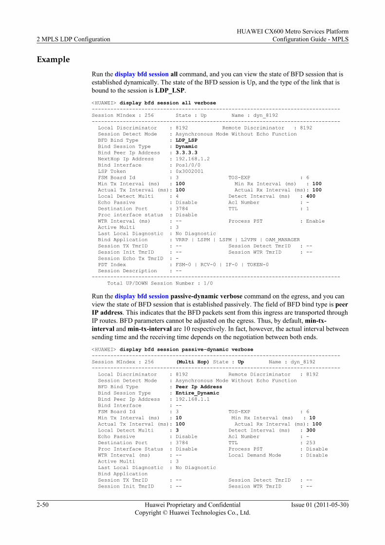
ExampleRun the display bfd session all command, and you can view the state of BFD session that isestablished dynamically. The state of the BFD session is Up, and the type of the link that isbound to the session is LDP_LSP.
<HUAWEI> display bfd session all verbose--------------------------------------------------------------------------------Session MIndex : 256 State : Up Name : dyn_8192-------------------------------------------------------------------------------- Local Discriminator : 8192 Remote Discriminator : 8192 Session Detect Mode : Asynchronous Mode Without Echo Function BFD Bind Type : LDP_LSP Bind Session Type : Dynamic Bind Peer Ip Address : 3.3.3.3 NextHop Ip Address : 192.168.1.2 Bind Interface : Pos1/0/0 LSP Token : 0x3002001 FSM Board Id : 3 TOS-EXP : 6 Min Tx Interval (ms) : 100 Min Rx Interval (ms) : 100 Actual Tx Interval (ms): 100 Actual Rx Interval (ms): 100 Local Detect Multi : 4 Detect Interval (ms) : 400 Echo Passive : Disable Acl Number : - Destination Port : 3784 TTL : 1 Proc interface status : Disable WTR Interval (ms) : -- Process PST : Enable Active Multi : 3 Last Local Diagnostic : No Diagnostic Bind Application : VRRP | LSPM | LSPM | L2VPN | OAM_MANAGER Session TX TmrID : -- Session Detect TmrID : -- Session Init TmrID : -- Session WTR TmrID : -- Session Echo Tx TmrID : - PDT Index : FSM-0 | RCV-0 | IF-0 | TOKEN-0 Session Description : ---------------------------------------------------------------------------------- Total UP/DOWN Session Number : 1/0
Run the display bfd session passive-dynamic verbose command on the egress, and you canview the state of BFD session that is established passively. The field of BFD bind type is peerIP address. This indicates that the BFD packets sent from this ingress are transported throughIP routes. BFD parameters cannot be adjusted on the egress. Thus, by default, min-tx-interval and min-tx-interval are 10 respectively. In fact, however, the actual interval betweensending time and the receiving time depends on the negotiation between both ends.
<HUAWEI> display bfd session passive-dynamic verbose--------------------------------------------------------------------------------Session MIndex : 256 (Multi Hop) State : Up Name : dyn_8192-------------------------------------------------------------------------------- Local Discriminator : 8192 Remote Discriminator : 8192 Session Detect Mode : Asynchronous Mode Without Echo Function BFD Bind Type : Peer Ip Address Bind Session Type : Entire_Dynamic Bind Peer Ip Address : 192.168.1.1 Bind Interface : -- FSM Board Id : 3 TOS-EXP : 6 Min Tx Interval (ms) : 10 Min Rx Interval (ms) : 10 Actual Tx Interval (ms): 100 Actual Rx Interval (ms): 100 Local Detect Multi : 3 Detect Interval (ms) : 300 Echo Passive : Disable Acl Number : - Destination Port : 3784 TTL : 253 Proc Interface Status : Disable Process PST : Disable WTR Interval (ms) : -- Local Demand Mode : Disable Active Multi : 3 Last Local Diagnostic : No Diagnostic Bind Application Session TX TmrID : -- Session Detect TmrID : -- Session Init TmrID : -- Session WTR TmrID : --
2 MPLS LDP ConfigurationHUAWEI CX600 Metro Services Platform
Configuration Guide - MPLS
2-50 Huawei Proprietary and ConfidentialCopyright © Huawei Technologies Co., Ltd.
Issue 01 (2011-05-30)
Session Echo Tx TmrID : - PDT Index : FSM-0 | RCV-0 | IF-0 | TOKEN-0 Session Description : ---------------------------------------------------------------------------------- Total UP/DOWN Session Number : 1/0
2.8 Configuring Manual LDP FRRBy configuring Manual LDP FRR, you can quickly switch traffic to the backup LSP when a linkfails, which ensures uninterrupted traffic transmission.
2.8.1 Establishing the Configuration TaskBefore configuring Manual LDP FRR, familiarize yourself with the applicable environment,complete the pre-configuration tasks, and obtain the required data. This can help you completethe configuration task quickly and accurately.
2.8.2 Enabling Manual LDP FRRBy configuring parameters on the ingress node, you can enable Manual LDP FRR.
2.8.3 (Optional) Configuring Manual LDP FRR Protection TimerBy configuring a Manual LDP FRR protection timer, you can ensure that the primary LDP LSPis not deleted.
2.8.4 (Optional) Allowing BFD to Modify the PSTYou need to permit the BFD session to modify the PST only when configuring BFD for ManualLDP FRR.
2.8.5 Checking the ConfigurationAfter the configuration of Manual LDP FRR, you can view information about Manual LDPFRR-LSPs and BFD-enabled interfaces.
2.8.1 Establishing the Configuration TaskBefore configuring Manual LDP FRR, familiarize yourself with the applicable environment,complete the pre-configuration tasks, and obtain the required data. This can help you completethe configuration task quickly and accurately.
Applicable EnvironmentLDP FRR provides MPLS with a fast reroute function to implement the local port-level backup.In addition, the data loss decreases.
Pre-configuration TasksBefore configuring LDP FRR, complete the following tasks:
l Configuring MPLSl Configuring MPLS LDP
If the LDP FRR is based on the BFD, you need to configure the one-hop BFD.
For details of the one-hop BFD, refer to "BFD Configuration" in the HUAWEI CX600 MetroServices Platform Configuration Guide - Reliability.
Data PreparationTo configure LDP FRR, you need the following data.
HUAWEI CX600 Metro Services PlatformConfiguration Guide - MPLS 2 MPLS LDP Configuration
Issue 01 (2011-05-30) Huawei Proprietary and ConfidentialCopyright © Huawei Technologies Co., Ltd.
2-51
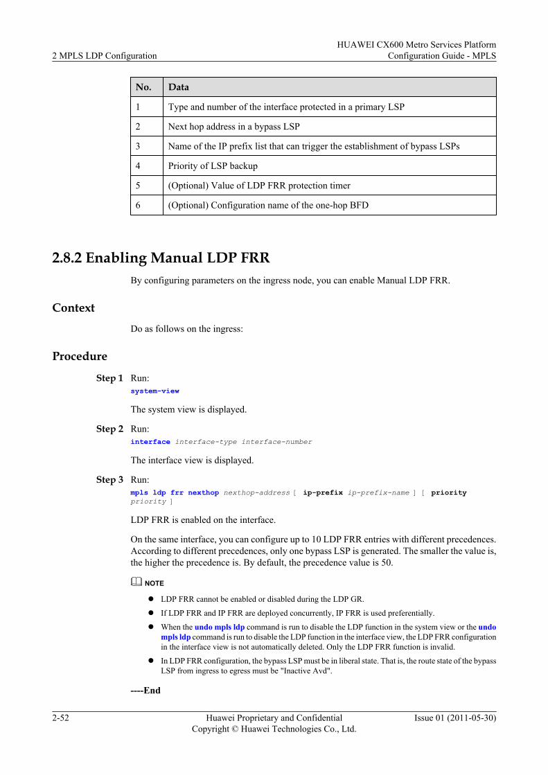
No. Data
1 Type and number of the interface protected in a primary LSP
2 Next hop address in a bypass LSP
3 Name of the IP prefix list that can trigger the establishment of bypass LSPs
4 Priority of LSP backup
5 (Optional) Value of LDP FRR protection timer
6 (Optional) Configuration name of the one-hop BFD
2.8.2 Enabling Manual LDP FRRBy configuring parameters on the ingress node, you can enable Manual LDP FRR.
ContextDo as follows on the ingress:
Procedure
Step 1 Run:system-view
The system view is displayed.
Step 2 Run:interface interface-type interface-number
The interface view is displayed.
Step 3 Run:mpls ldp frr nexthop nexthop-address [ ip-prefix ip-prefix-name ] [ priority priority ]
LDP FRR is enabled on the interface.
On the same interface, you can configure up to 10 LDP FRR entries with different precedences.According to different precedences, only one bypass LSP is generated. The smaller the value is,the higher the precedence is. By default, the precedence value is 50.
NOTE
l LDP FRR cannot be enabled or disabled during the LDP GR.
l If LDP FRR and IP FRR are deployed concurrently, IP FRR is used preferentially.
l When the undo mpls ldp command is run to disable the LDP function in the system view or the undompls ldp command is run to disable the LDP function in the interface view, the LDP FRR configurationin the interface view is not automatically deleted. Only the LDP FRR function is invalid.
l In LDP FRR configuration, the bypass LSP must be in liberal state. That is, the route state of the bypassLSP from ingress to egress must be "Inactive Avd".
----End
2 MPLS LDP ConfigurationHUAWEI CX600 Metro Services Platform
Configuration Guide - MPLS
2-52 Huawei Proprietary and ConfidentialCopyright © Huawei Technologies Co., Ltd.
Issue 01 (2011-05-30)
2.8.3 (Optional) Configuring Manual LDP FRR Protection TimerBy configuring a Manual LDP FRR protection timer, you can ensure that the primary LDP LSPis not deleted.
ContextDo as follows on the ingress:
Procedure
Step 1 Run:system-view
The system view is displayed.
Step 2 Run:interface interface-type interface-number
The interface view is displayed.
Step 3 Run:mpls ldp frr timer protect-time protect-time
The LDP FRR protection timer is configured on the interface.
----End
Follow-up ProcedureWhen the LDP FRR protection timer is enabled, and the LDP session goes Down due to an activelink failure, the LDP LSP along the active link is not deleted until one of the following conditionsis meet:
l LDP FRR protection timer expires.l The active link route is deleted.l The interface of the active link goes Down.
2.8.4 (Optional) Allowing BFD to Modify the PSTYou need to permit the BFD session to modify the PST only when configuring BFD for ManualLDP FRR.
ContextThe procedure is only applicable to configure the LDP FRR based on BFD.
Do as follows on the ingress:
Procedure
Step 1 Run:system-view
The system view is displayed.
HUAWEI CX600 Metro Services PlatformConfiguration Guide - MPLS 2 MPLS LDP Configuration
Issue 01 (2011-05-30) Huawei Proprietary and ConfidentialCopyright © Huawei Technologies Co., Ltd.
2-53
Step 2 Run:bfd cfg-name
The created BFD session view is displayed.
Step 3 Run:process-pst
BFD is allowed to modify the PST.
Step 4 Run:commit
The configuration is committed.
By default, BFD does not modify the PST.
----End
2.8.5 Checking the ConfigurationAfter the configuration of Manual LDP FRR, you can view information about Manual LDPFRR-LSPs and BFD-enabled interfaces.
PrerequisiteThe configurations of the LDP FRR function are complete.
Procedurel Run the display mpls lsp command to check information about LSPs enabled with LDP
FRR.
l Run the display bfd interface [ interface-type interface-number ] command to checkinformation about the BFD interface.
----End
2.9 Configuring LDP Auto FRRBy configuring a policy for triggering the setup of backup LSPs, you can control the setup ofbackup LSPs.
2.9.1 Establishing the Configuration TaskBefore configuring LDP Auto FRR, familiarize yourself with the applicable environment,complete the pre-configuration tasks, and obtain the required data. This can help you completethe configuration task quickly and accurately.
2.9.2 Enabling LDP Auto FRRTo configure LDP Auto FRR, you need to configure the ingress or transit node.
2.9.3 Checking the ConfigurationAfter the configuration of LDP Auto FRR, you can view information about LDP Auto FRR-LSPs.
2 MPLS LDP ConfigurationHUAWEI CX600 Metro Services Platform
Configuration Guide - MPLS
2-54 Huawei Proprietary and ConfidentialCopyright © Huawei Technologies Co., Ltd.
Issue 01 (2011-05-30)
2.9.1 Establishing the Configuration TaskBefore configuring LDP Auto FRR, familiarize yourself with the applicable environment,complete the pre-configuration tasks, and obtain the required data. This can help you completethe configuration task quickly and accurately.
Applicable EnvironmentIn a network where LDP Fast Reroute (FRR) is configured, traffic is fast switched to the backupLSP when a link becomes faulty. In this case, traffic is uninterrupted and is switched within 50ms.
There are two types of LDP FRR: manual LDP FRR and LDP Auto FRR.l In the mode of manual LDP FRR, you need to configure a backup LSP by specifying the
outbound interfaces or the next hops. The configuration procedure is complex, but thebackup LSP can be specified. Therefore, manual LDP FRR is more flexible, and isapplicable to the network with a simple structure.
l In the mode of LDP Auto FRR, a backup LSP can be automatically generated accordingto the triggering policy. The configuration procedure is more simplified. In addition, loopsthat may occur during the manual configuration can be avoided. Therefore, LDP Auto FRRis applicable to the large-scale network with a complicated structure.
Pre-configuration TasksBefore configuring LDP Auto FRR, complete the following tasks:
l Configuring IP addresses for interfaces to ensure that neighboring nodes are reachable atthe network layer
l Configuring IS-IS to advertise the network segments connecting to interfaces on each nodeand to advertise the routes of hosts with Label Switching Router (LSR) IDs
l Configuring MPLS LDPl Configuring IS-IS Auto FRR
Data PreparationTo configure LDP Auto FRR, you need the following data.
No. Data
1 Type and number of the interface where a backup LSP is set up
2 Policy for triggering LDP to set up backup LSPs
2.9.2 Enabling LDP Auto FRRTo configure LDP Auto FRR, you need to configure the ingress or transit node.
Procedure
Step 1 Run:
HUAWEI CX600 Metro Services PlatformConfiguration Guide - MPLS 2 MPLS LDP Configuration
Issue 01 (2011-05-30) Huawei Proprietary and ConfidentialCopyright © Huawei Technologies Co., Ltd.
2-55
system-view
The system view is displayed.
Step 2 Run:mpls ldp
The MPLS LDP view is displayed.
Step 3 Run:auto-frr lsp-trigger { all | host | ip-prefix ip-prefix-name | none }
The policy for triggering LDP to set up backup LSPs is configured.
By default, the backup routes with 32-bit addresses trigger LDP to setup backup LSPs.
The auto-frr lsp-trigger command is restricted by the lsp-trigger command. If both the auto-frr lsp-trigger command and the lsp-trigger command are configured, the established backupLSPs satisfy both the policy for triggering the setup of LSPs by LDP and the policy for triggeringthe setup of backup LSPs by LDP.
NOTE
During LDP GR, changing the policy for triggering the setup of backup LSPs is not allowed.
----End
2.9.3 Checking the ConfigurationAfter the configuration of LDP Auto FRR, you can view information about LDP Auto FRR-LSPs.
PrerequisiteAll LDP Auto FRR configurations are complete.
Procedurel Run the display mpls lsp command to view information about the established backup LSP
after LDP Auto FRR is enabled.
----End
ExampleEnable LDP Auto FRR. You can view that the backup LSP to the destination 2.2.2.9/32 hasalready been set up. The configuration result is as follows:
[HUAWEI] display mpls lsp
------------------------------------------------------------------------------- LSP Information: LDP LSP-------------------------------------------------------------------------------FEC In/Out Label In/Out IF Vrf Name2.2.2.9/32 NULL/3 -/Pos1/0/0**LDP FRR** /1025 /Pos1/0/12.2.2.9/32 1024/3 -/Pos1/0/0 **LDP FRR** /1025 /Pos1/0/13.3.3.9/32 NULL/3 -/Pos1/0/1 **LDP FRR** /1025 /Pos1/0/03.3.3.9/32 1025/3 -/Pos1/0/1 **LDP FRR** /1025 /Pos1/0/0
2 MPLS LDP ConfigurationHUAWEI CX600 Metro Services Platform
Configuration Guide - MPLS
2-56 Huawei Proprietary and ConfidentialCopyright © Huawei Technologies Co., Ltd.
Issue 01 (2011-05-30)
4.4.4.9/32 NULL/1026 -/Pos1/0/1 **LDP FRR** /1026 /Pos1/0/04.4.4.9/32 1026/1026 -/Pos1/0/1 **LDP FRR** /1026 /Pos1/0/010.1.3.0/24 1027/3 -/Pos1/0/110.1.4.0/24 1028/3 -/Pos1/0/1 **LDP FRR** /1027 /Pos1/0/0
2.10 Configuring Synchronization Between LDP and IGPBy configuring LDP and IGP synchronization, you can delay the route switchback bysuppressing the setup of IGP neighbor relationship till an LDP session is established.
2.10.1 Establishing the Configuration TaskBefore configuring LDP and IGP synchronization, familiarize yourself with the applicableenvironment, complete the pre-configuration tasks, and obtain the required data. This can helpyou complete the configuration task quickly and accurately.
2.10.2 Enabling Synchronization Between LDP and IGPTo enable LDP and IGP synchronization, you need to configure the interfaces of both ends ofthe link between the crossing node of active and standby links and the LDP neighboring node.
2.10.3 (Optional) Setting the Hold-down Timer ValueYou can set the value of a hold-down timer, that is, an interval during which an interface waitsfor the setup of an LDP session without setting up the OSPF neighbor relationship.
2.10.4 (Optional) Setting the Hold-max-cost Timer ValueYou can set the value of a hold-max-cost timer, that is, an interval for advertising the maximumcost through LSAs generated locally.
2.10.5 (Optional) Setting the Delay Timer ValueYou can set the value of a delay timer, that is, an period for waiting for the setup of an LSP.
2.10.6 Checking the ConfigurationAfter the configuration of LDP and IGP synchronization, you can view the synchronizationinformation and route management information on interfaces enabled with LDP and IGPsynchronization.
2.10.1 Establishing the Configuration TaskBefore configuring LDP and IGP synchronization, familiarize yourself with the applicableenvironment, complete the pre-configuration tasks, and obtain the required data. This can helpyou complete the configuration task quickly and accurately.
Applicable Environment
In the networking where primary and backup LSPs are used, synchronization between LDP andIGP is applied to avoid traffic loss in case the primary LSP fails. The situations are as follows:l When the primary LSP fails, the IGP traffic and LSP traffic are switched to the backup
LSP. When the primary LSP recovers, IGP converges faster than the creation of the LDPsession. Thus, IGP traffic is switched back to the primary LSP before the LDP session isset up. This causes the loss of LSP traffic.
l When the primary LSP runs normally whereas the LDP sessions between the nodes alongthe primary LSP fail, the LSP traffic is switched to the backup LSP. The IGP traffic,however, is still transmitted along the primary LSP. As a result, the LSP traffic is lost.
HUAWEI CX600 Metro Services PlatformConfiguration Guide - MPLS 2 MPLS LDP Configuration
Issue 01 (2011-05-30) Huawei Proprietary and ConfidentialCopyright © Huawei Technologies Co., Ltd.
2-57
Pre-configuration TasksBefore configuring synchronization between LDP and IGP, complete the following tasks:
l Configuring MPLS functionsl Configuring MPLS LDP functions globally and on all interfaces
Data PreparationTo configure synchronization between LDP and IGP, you need the following data.
No. Data
1 Type and number of the interface on which the backup LSP is set up
2 Type and number of the interface on which the timer is configured
3 Timer value
2.10.2 Enabling Synchronization Between LDP and IGPTo enable LDP and IGP synchronization, you need to configure the interfaces of both ends ofthe link between the crossing node of active and standby links and the LDP neighboring node.
Procedurel When OSPF runs as an IGP, do as follows on the interfaces of both ends of the link between
the crossing node of the active link and the standby link and the LDP neighboring node onthe active link:1. Run:
system-view
The system view is displayed.2. Run:
interface interface-type interface-number
The interface view is displayed.3. Run:
ospf ldp-sync
Synchronization between LDP and OSPF is enabled on the interface to be protected.l When IS-IS runs as an IGP, do as follows on the interfaces of both ends of the link between
the crossing node of active and standby links and the LDP neighboring node on the activelink:1. Run:
system-view
The system view is displayed.2. Run:
interface interface-type interface-number
The interface view is displayed.
2 MPLS LDP ConfigurationHUAWEI CX600 Metro Services Platform
Configuration Guide - MPLS
2-58 Huawei Proprietary and ConfidentialCopyright © Huawei Technologies Co., Ltd.
Issue 01 (2011-05-30)
3. Run:isis enable process-id
IS-IS is enabled.4. Run:
isis ldp-sync
Synchronization between LDP and IS-IS is enabled on the interface to be protected.
----End
2.10.3 (Optional) Setting the Hold-down Timer ValueYou can set the value of a hold-down timer, that is, an interval during which an interface waitsfor the setup of an LDP session without setting up the OSPF neighbor relationship.
ContextDo as follows on the interface:
Procedurel When OSPF runs as an IGP, do as follows on the interfaces of both ends of the link between
the crossing node of active and standby links and the LDP neighboring node on the activelink:1. Run:
system-view
The system view is displayed.2. Run:
interface interface-type interface-number
The interface view is displayed.3. Run:
ospf timer ldp-sync hold-down value
The interval OSPF should wait for an LDP session to be established is set.
By default, the hold-down timer value is 10 seconds.l When IS-IS runs as an IGP, do as follows on the interfaces of both ends of the link between
the crossing node of active and standby links and the LDP neighboring node on the activelink:1. Run:
system-view
The system view is displayed.2. Run:
interface interface-type interface-number
The interface view is displayed.3. Run:
isis timer ldp-sync hold-down value
The interval IS-IS should wait for an LDP session to be established is set.
HUAWEI CX600 Metro Services PlatformConfiguration Guide - MPLS 2 MPLS LDP Configuration
Issue 01 (2011-05-30) Huawei Proprietary and ConfidentialCopyright © Huawei Technologies Co., Ltd.
2-59
By default, the hold-down timer value is 10 seconds.
----End
2.10.4 (Optional) Setting the Hold-max-cost Timer ValueYou can set the value of a hold-max-cost timer, that is, an interval for advertising the maximumcost through LSAs generated locally.
ContextDo as follows on the interface:
Procedurel When OSPF runs as an IGP, do as follows on the interfaces of both ends of the link between
the crossing node of active and standby links and the LDP neighboring node on the activelink:1. Run:
system-view
The system view is displayed.2. Run:
interface interface-type interface-number
The interface view is displayed.3. Run:
ospf timer ldp-sync hold-max-cost { value | infinite }
The interval for advertising the maximum cost in the LSAs of local LSRs throughOSPF is set.
By default, the value of the hold-max-cost timer is 10 seconds.
You can choose different parameters as required.– When OSPF carries only LDP services, to ensure that the route selected by OSPF
is always the same as the LDP LSP, infinite need to be specified.– When OSPF carries multiple services including LDP services, to ensure that OSPF
route selection and other services still run normally in case the LDP session of theprimary LSP fails, value can be specified.
If this command is configured repeatedly, the latest configuration takes effect.l When IS-IS runs as an IGP, do as follows on the interfaces of both ends of the link between
the crossing node of active and standby links and the LDP neighboring node on the activelink:1. Run:
system-view
The system view is displayed.2. Run:
interface interface-type interface-number
The interface view is displayed.
2 MPLS LDP ConfigurationHUAWEI CX600 Metro Services Platform
Configuration Guide - MPLS
2-60 Huawei Proprietary and ConfidentialCopyright © Huawei Technologies Co., Ltd.
Issue 01 (2011-05-30)
3. Run:isis timer ldp-sync hold-max-cost { value | infinite }
The interval for advertising the maximum cost in the LSAs of local LSRs through IS-IS is set.
By default, the value of the hold-max-cost timer is 10 seconds.
You can choose different parameters as required.– When IS-IS carries only LDP services, to ensure that the route selected by IS-IS
is always the same as the LDP LSP, infinite need to be specified.– When IS-IS carries multiple services including LDP services, to ensure that IS-IS
route selection and other services still run normally in case the LDP session of theprimary LSP fails, value can be specified.
If this command is configured repeatedly, the latest configuration takes effect.
----End
2.10.5 (Optional) Setting the Delay Timer ValueYou can set the value of a delay timer, that is, an period for waiting for the setup of an LSP.
ContextDo as follows on the interfaces of both ends of the link between the crossing node of active andstandby links and the LDP neighboring node on the active link:
ProcedureStep 1 Run:
system-view
The system view is displayed.
Step 2 Run:interface interface-type interface-number
The interface view is displayed.
Step 3 Run:mpls ldp timer igp-sync-delay value
The period of waiting for the LSP setup after the establishment of the LDP session is set.
By default, the value of the delay timer is 10 seconds.
----End
2.10.6 Checking the ConfigurationAfter the configuration of LDP and IGP synchronization, you can view the synchronizationinformation and route management information on interfaces enabled with LDP and IGPsynchronization.
PrerequisiteThe configurations of the synchronization between LDP and IGP function are complete.
HUAWEI CX600 Metro Services PlatformConfiguration Guide - MPLS 2 MPLS LDP Configuration
Issue 01 (2011-05-30) Huawei Proprietary and ConfidentialCopyright © Huawei Technologies Co., Ltd.
2-61
Procedurel Run the display ospf ldp-sync interface { all | interface-type interface-number } command
to check information about synchronization between LDP and OSPF on the interface.
l Run the display isis [ process-id | vpn-instance vpn-instance-name ] ldp-sync interfacecommand to check information about synchronization between LDP and IS-IS on theinterface.
l Run the display rm interface [ interface-type interface-number | vpn-instance vpn-instance-name ] command to check information about the route management.
----End
Example
l If the configurations succeed, run the display ospf ldp-sync or display isis ldp-synccommand, and you can view that the status of the interface configured with synchronizationbetween LDP and IGP is Sync-Achieved.
l Run the display rm interface command, you can view that the LDP-ISIS or LDP-OSPFis enabled.
2.11 Configuring Synchronization Between LDP and StaticRoutes
By configuring synchronization between LDP and static routes, you can switch traffic from thefaulty primary link to the backup link by suppressing the activation of static routes and delaytraffic switchback to synchronize LDP and static routes.
2.11.1 Establishing the Configuration TaskBefore configuring synchronization between LDP and static routes, familiarize yourself withthe applicable environment, complete the pre-configuration tasks, and obtain the required data.This can help you complete the configuration task quickly and accurately.
2.11.2 Enabling Synchronization Between LDP and Static RoutesOn an MPLS network with primary and backup LSPs, LSRs establish LSPs based on staticroutes. By enabling synchronization between LDP and static routes on both ends of the twolinks, you can avoid MPLS traffic interruption.
2.11.3 (Optional) Setting a Hold-down TimerWhen the primary link recovers, a static route does not become active immediately. Instead, thestatic route becomes active only when an LDP session is established before the Hold-down timerexpires. Then traffic is switched back to the primary link.
2.11.4 Checking the ConfigurationAfter synchronization between LDP and static routes is configured, you can check the status ofall the interfaces configured with synchronization between LDP and static routes.
2.11.1 Establishing the Configuration TaskBefore configuring synchronization between LDP and static routes, familiarize yourself withthe applicable environment, complete the pre-configuration tasks, and obtain the required data.This can help you complete the configuration task quickly and accurately.
2 MPLS LDP ConfigurationHUAWEI CX600 Metro Services Platform
Configuration Guide - MPLS
2-62 Huawei Proprietary and ConfidentialCopyright © Huawei Technologies Co., Ltd.
Issue 01 (2011-05-30)
Applicable EnvironmentSynchronization between LDP and static routes is applicable to an MPLS network with primaryand backup LSPs. On such an MPLS network, LSRs establish LSPs based on static routes. Whenthe LDP session of the primary link becomes faulty (the fault is not caused by a link failure) orthe primary link recovers, synchronization between LDP and static routes minimizes traffic lossduring traffic switchover and switchback. As shown in Figure 2-1, there is a static route betweenLSRA and LSRD, and an LSP is established between the two devices based on the static route.Normally, the link LSRA→LSRB→LSRD is preferred.
l In a switchover scenario, when the LDP session of the primary link becomes faulty (thefault is not caused by a link failure), traffic transmitted through the static route is notswitched to the backup link. As a result, MPLS traffic on the primary link is interrupted.Normally, after an LDP session is established, MPLS traffic is forwarded along the primarylink LSRA→LSRB→LSRD. If the LDP session between LSRA and LSRB is disconnected,the LSP is immediately switched to the backup link LSRA→LSRC→LSRD. Because thelink between LSRA and LSRB works properly, traffic transmitted through the static routeis not switched to the backup link. As a result, LDP is not synchronous with the static route,and MPLS traffic is interrupted.After synchronization between LDP and static routes is enabled, when the LDP sessiongoes Down, traffic is automatically switched to the backup link, thus ensuring non-stoptraffic forwarding.
l In a switchback scenario, when the primary link recovers, traffic transmitted through astatic route is first switched back to the primary link because the static route convergesfaster than LDP. However, the backup LSP becomes unavailable, and the primary LSP hasnot been established. As a result, MPLS traffic is interrupted.When the link between LSRA and LSRB becomes faulty, traffic is immediately switchedto the backup link LSRA→LSRC→LSRD. After the link between LSRA and LSRBrecovers, traffic transmitted through the static route is immediately switched to the primarylink LSRA→LSRB→LSRD. However, the backup LSP becomes unavailable, and theprimary LSP has not recovered. Therefore, traffic is interrupted.After synchronization between LDP and static routes is enabled, when the primary LSP isestablished, traffic is switched back to the primary link, thus ensuring non-stop trafficforwarding.
HUAWEI CX600 Metro Services PlatformConfiguration Guide - MPLS 2 MPLS LDP Configuration
Issue 01 (2011-05-30) Huawei Proprietary and ConfidentialCopyright © Huawei Technologies Co., Ltd.
2-63
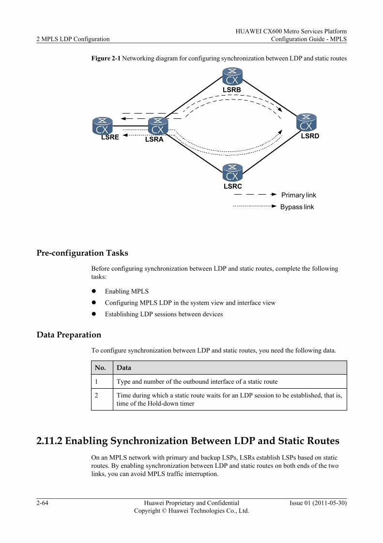
Figure 2-1 Networking diagram for configuring synchronization between LDP and static routes
LSRA
LSRB
LSRC
LSRD
Primary link
Bypass link
LSRE
Pre-configuration Tasks
Before configuring synchronization between LDP and static routes, complete the followingtasks:
l Enabling MPLS
l Configuring MPLS LDP in the system view and interface view
l Establishing LDP sessions between devices
Data Preparation
To configure synchronization between LDP and static routes, you need the following data.
No. Data
1 Type and number of the outbound interface of a static route
2 Time during which a static route waits for an LDP session to be established, that is,time of the Hold-down timer
2.11.2 Enabling Synchronization Between LDP and Static RoutesOn an MPLS network with primary and backup LSPs, LSRs establish LSPs based on staticroutes. By enabling synchronization between LDP and static routes on both ends of the twolinks, you can avoid MPLS traffic interruption.
2 MPLS LDP ConfigurationHUAWEI CX600 Metro Services Platform
Configuration Guide - MPLS
2-64 Huawei Proprietary and ConfidentialCopyright © Huawei Technologies Co., Ltd.
Issue 01 (2011-05-30)
ContextWith synchronization between LDP and static routes, you can switch traffic from the faultyprimary link to the backup link by suppressing the activation of static routes and delay trafficswitchback to the primary link, thus ensuring that LDP is synchronous with static routes.
NOTE
Only the static route with a specified outbound interface can be configured with synchronization betweenLDP and static routes.
Do as follows on devices on both ends of the primary and backup links:
Procedure
Step 1 Run:system-view
The system view is displayed.
Step 2 Run:ip route-static ip-address { mask | mask-length } interface-type interface-number [ nexthop-address ] [ preference preference | tag tag ] * ldp-sync [ description text ]
Synchronization between LDP and static routes is configured.
By default, synchronization between LDP and static routes is not enabled.
----End
2.11.3 (Optional) Setting a Hold-down TimerWhen the primary link recovers, a static route does not become active immediately. Instead, thestatic route becomes active only when an LDP session is established before the Hold-down timerexpires. Then traffic is switched back to the primary link.
ContextAfter a Hold-down timer is set on an interface, the static route enabled with synchronizationbetween LDP and static routes becomes inactive temporarily and waits for an LDP session tobe established before the Hold-down timer expires. This implements synchronization betweenLDP and static routes. If the Hold-down timer expires, the static route becomes active regardlessof whether the LDP session has been established.
NOTE
Setting a Hold-down timer on loopback interfaces or null interfaces is not allowed.
Procedure
Step 1 Run:system-view
The system view is displayed.
Step 2 Run:interface interface-type interface-number
HUAWEI CX600 Metro Services PlatformConfiguration Guide - MPLS 2 MPLS LDP Configuration
Issue 01 (2011-05-30) Huawei Proprietary and ConfidentialCopyright © Huawei Technologies Co., Ltd.
2-65
The outbound interface view of the primary link of the static route is displayed.
Step 3 Run:static-route timer ldp-sync hold-down { timer | infinite }
A Hold-down timer is set.
By default, a Hold-down timer is set to 10 seconds.
l If the Hold-down timer is set to 0 seconds, it indicates that synchronization between LDPand static routes is disabled on an interface.
l If the Hold-down timer is set to infinite, it indicates that the timer never expires. In this case,the static route becomes active and MPLS traffic is switched only after an LDP session isestablished.
----End
2.11.4 Checking the ConfigurationAfter synchronization between LDP and static routes is configured, you can check the status ofall the interfaces configured with synchronization between LDP and static routes.
PrerequisiteThe configurations of synchronization between LDP and static routes are complete.
Procedurel Run the display static-route ldp-sync [ interface interface-type interface-number ]
command to check the status of the interface configured with synchronization between LDPand static routes.
If the parameter interface interface-type interface-number is specified, only the status ofa specified interface is displayed.
----End
ExampleRun the display static-route ldp-sync command after configuring synchronization betweenLDP and static routes. If the following is displayed, it means that the configuration succeeds.
<HUAWEI> display static-route ldp-syncTotal number of routes enable LDP-sync: 1--------------------------------------------------------interface GigabitEthernet1/0/0Enable ldp-sync static routes number: 1Static-route ldp-sync holddown timer: 10sSync State: NormalDest = 1.1.1.1, Mask = 32, NextHop = 2.2.2.2---------------------------------------------------------
2.12 Configuring LDP GTSMBy configuring LDP GTSM, you can detect TTLs to prevent attacks.
2.12.1 Establishing the Configuration Task
2 MPLS LDP ConfigurationHUAWEI CX600 Metro Services Platform
Configuration Guide - MPLS
2-66 Huawei Proprietary and ConfidentialCopyright © Huawei Technologies Co., Ltd.
Issue 01 (2011-05-30)
Before configuring LDP GTSM, familiarize yourself with the applicable environment, completethe pre-configuration tasks, and obtain the required data. This can help you complete theconfiguration task quickly and accurately.
2.12.2 Configuring LDP GTSMTo configure LDP GTSM, you need to configure both LDP peers.
2.12.3 Checking the ConfigurationAfter the configuration of LDP GTSM, you can view GTSM statistics.
2.12.1 Establishing the Configuration TaskBefore configuring LDP GTSM, familiarize yourself with the applicable environment, completethe pre-configuration tasks, and obtain the required data. This can help you complete theconfiguration task quickly and accurately.
Applicable Environment
The Generalized TTL Security Mechanism (GTSM) prevents attacks by using the TTL detection.An attacker simulates real LDP unicast packets and sends the packets in a large quantity to anode. After receiving the packets, an interface of the LSR directly sends the packets to LDP ofthe control plane if the interface finds that the packets are sent by the local node, without checkingthe validity of the packets. Because the control plane of the node needs to process the "legal"packets, the system becomes abnormally busy and CPU usage is high.
GTSM protects the node by checking whether the TTL value in the IP packet header is withina pre-defined range, and thus enhances the system security.
Pre-configuration Tasks
Before configuring basic LDP GTSM functions, complete the following tasks:
l Enabling MPLS and MPLS LDP
Data Preparation
To configure the basic LDP GTSM functions, you need the following data.
No. Data
1 LSR ID of an LDP peer
2 Maximum number of valid hops permitted by GTSM
2.12.2 Configuring LDP GTSMTo configure LDP GTSM, you need to configure both LDP peers.
Context
Do as follows on the two LDP peers that need to be configured with GTSM:
HUAWEI CX600 Metro Services PlatformConfiguration Guide - MPLS 2 MPLS LDP Configuration
Issue 01 (2011-05-30) Huawei Proprietary and ConfidentialCopyright © Huawei Technologies Co., Ltd.
2-67
Procedure
Step 1 Run:system-view
The system view is displayed.
Step 2 Run:mpls ldp
The MPLS LDP view is displayed.
Step 3 Run:gtsm peer ip-address valid-ttl-hops hops
LDP GTSM is configured.
If the value of hops is set to the maximum number of valid hops permitted by GTSM, when theTTL values carried in the packets sent by an LDP peer are within the range [255 - hops + 1,255], the packets are received; otherwise, the packets are discarded.
----End
2.12.3 Checking the ConfigurationAfter the configuration of LDP GTSM, you can view GTSM statistics.
PrerequisiteThe configurations of the LDP GTSM function are complete.
Procedurel Run the display gtsm statistics { slot-id | all } command to check the GTSM statistics.
----End
ExampleRun the display gtsm statistics command, and you can view the GTSM statistics in each slot,including the total number of LDP, BGP, BGP4+, and OSPF packets and the number of packetsthat are allowed to pass through or the number of dropped packets.
<HUAWEI> display gtsm statistics allGTSM Statistics Table----------------------------------------------------------------SlotId Protocol Total Counters Drop Counters Pass Counters---------------------------------------------------------------- 6 BGP 0 0 0 6 BGPv6 0 0 0 6 OSPF 0 0 0 6 LDP 11 0 11----------------------------------------------------------------
2.13 Configuring LDP GRBy configuring LDP GR, you can realize the uninterrupted forwarding during the master/slaveswitchover or the protocol restart, which can limit the protocol flapping on the control plane.
2 MPLS LDP ConfigurationHUAWEI CX600 Metro Services Platform
Configuration Guide - MPLS
2-68 Huawei Proprietary and ConfidentialCopyright © Huawei Technologies Co., Ltd.
Issue 01 (2011-05-30)
2.13.1 Establishing the Configuration TaskBefore configuring LDP GR, familiarize yourself with the applicable environment, completethe pre-configuration tasks, and obtain the required data. This can help you complete theconfiguration task quickly and accurately.
2.13.2 Enabling LDP GRTo enable LDP GR, you need to configure both the GR Restarter and its neighbor.
2.13.3 (Optional) Configuring GR Restarter TimerYou can set the value of a GR Restarter timer, that is, the Neighbor-liveness timer.
2.13.4 (Optional) Configuring the timer of GR HelperYou can set the values of GR Helper timers, that is, the Reconnect timer for an LDP session andthe LSP Recovery timer.
2.13.5 Checking the ConfigurationAfter the configuration of LDP GR, you can view GR information about all protocols related toMPLS, LDP information, and LDP session information.
2.13.1 Establishing the Configuration TaskBefore configuring LDP GR, familiarize yourself with the applicable environment, completethe pre-configuration tasks, and obtain the required data. This can help you complete theconfiguration task quickly and accurately.
Applicable EnvironmentIt is necessary to enable LDP GR to maintain normal forwarding and resume the LDP sessionand establish LSPs after the switchover and system update.
NOTE
In practical applications, the system-level GR is usually configured in the hardware environment with dualmain control boards. In this manner, the service can be forwarded when the main control board fails.
Pre-configuration TasksBefore configuring LDP GR, complete the following tasks:
l Configuring the IGP GR functionl Configuring the local MPLS LDP session
Data PreparationTo configure LDP GR, you need the following data.
No. Data
1 MPLS LSR ID of the local node
2 Value of the Reconnect timer of the LDP session
3 Value of the LDP Neighbor-liveness timer
4 Value of the LDP Recovery timer
HUAWEI CX600 Metro Services PlatformConfiguration Guide - MPLS 2 MPLS LDP Configuration
Issue 01 (2011-05-30) Huawei Proprietary and ConfidentialCopyright © Huawei Technologies Co., Ltd.
2-69
2.13.2 Enabling LDP GRTo enable LDP GR, you need to configure both the GR Restarter and its neighbor.
Context
Do as follows on the LDP GR Restarter and its neighbor nodes:
Procedure
Step 1 Run:system-view
The system view is displayed.
Step 2 Run:mpls lsr-id lsr-id
The local LSR ID is configured.
Step 3 Run:mpls
The MPLS function is enabled on the local node and the MPLS view is displayed.
Step 4 Run:quit
Return to the system view.
Step 5 Run:mpls ldp
The LDP function is enabled on the local node and the LDP view is displayed.
Step 6 Run:graceful-restart
The GR function is enabled.
By default, the LDP GR function is disabled.
NOTE
l When the LDP GR is enabled or disabled, the LDP session is renewed.
l During the LDP GR process, the undo mpls ldp and reset mpls ldp commands are not permitted.
l During the LDP GR process, the modification of the LSP trigger policy through the lsp-trigger,propagate mapping and lsp-trigger bgp-label-route commands is invalid.
l During the LDP GR process, you are not permitted to run the mpls ldp frr nexthop command to enablethe LDP FRR. Alternatively, run the undo mpls ldp frr nexthop command to disable the LDP FRR.
----End
2.13.3 (Optional) Configuring GR Restarter TimerYou can set the value of a GR Restarter timer, that is, the Neighbor-liveness timer.
2 MPLS LDP ConfigurationHUAWEI CX600 Metro Services Platform
Configuration Guide - MPLS
2-70 Huawei Proprietary and ConfidentialCopyright © Huawei Technologies Co., Ltd.
Issue 01 (2011-05-30)
ContextDo as follows on the GR restarter:
NOTE
Modifying the values of the LDP GR timers may lead to reestablishment of LDP sessions.
Procedure
Step 1 Run:system-view
The system view is displayed.
Step 2 Run:mpls ldpThe MPLS LDP view is displayed.
Step 3 Run:graceful-restart timer neighbor-liveness time
The value of the Neighbor-liveness timer is set.
By default, the value of the Neighbor-liveness timer is 600 seconds.
----End
2.13.4 (Optional) Configuring the timer of GR HelperYou can set the values of GR Helper timers, that is, the Reconnect timer for an LDP session andthe LSP Recovery timer.
ContextDo as follows on the GR Helper:
NOTE
If any timer value related to LDP GR is modified, the LDP session is recreated.
Procedure
Step 1 Run:system-view
The system view is displayed.
Step 2 Run:mpls ldp
The MPLS LDP view is displayed.
Step 3 Run:graceful-restart timer reconnect time
The time of the Reconnect timer for the LDP session is set.
By default, the time of the Reconnect timer is set to 300 seconds.
HUAWEI CX600 Metro Services PlatformConfiguration Guide - MPLS 2 MPLS LDP Configuration
Issue 01 (2011-05-30) Huawei Proprietary and ConfidentialCopyright © Huawei Technologies Co., Ltd.
2-71
Step 4 Run:graceful-restart timer recovery time
The time of the LSP Recovery timer is set.
By default, the time of the LSP Recovery timer is set to 300 seconds.
----End
2.13.5 Checking the ConfigurationAfter the configuration of LDP GR, you can view GR information about all protocols related toMPLS, LDP information, and LDP session information.
PrerequisiteThe configurations of the LDP GR function are complete.
Procedurel Run the display mpls graceful-restart command to check information about GR of all
protocols related to MPLS.l Run the display mpls ldp [ all ] [ verbose ] command to check information about LDP.l Run the display mpls ldp session [ all ] [ verbose ] command to check information about
the LDP session.
----End
Example
l Run the display mpls ldp command, and you can view that the state of Graceful Restartis On. That is, LDP GR is enabled.
l Run the display mpls ldp command or the display mpls ldp session verbose command,and you can view the values of LDP session Reconnect timer, Neighbor-liveness timer,and LSP Recovery timer.
2.14 Maintaining MPLS LDPThe operations of MPLS LDP maintenance include deleting MPLS statistics, detectingconnectivity and reachability of an LSP, and configuring the trap function on an LDP LSP.
2.14.1 Resetting LDPResetting LDP may temporarily affect the reestablishment of the LSP. Take care to reset LDP.
2.14.2 Clearing MPLS StatisticsBy running the reset command, you can delete MPLS statistics.
2.14.3 Checking the LSP Connectivity and ReachabilityBy running the ping or tracert command, you can detect connectivity or reachability of an LSP.
2.14.4 Enabling the Trap Function of LSPBy configuring the trap function on an LSP, you can notify the NMS of the changes of the LSPstatus.
2 MPLS LDP ConfigurationHUAWEI CX600 Metro Services Platform
Configuration Guide - MPLS
2-72 Huawei Proprietary and ConfidentialCopyright © Huawei Technologies Co., Ltd.
Issue 01 (2011-05-30)
2.14.1 Resetting LDPResetting LDP may temporarily affect the reestablishment of the LSP. Take care to reset LDP.
Context
CAUTIONResetting LDP may temporarily affect the reestablishment of the LSP. Take care to reset LDP.
Resetting LDP is prohibited during the LDP GR.
After you confirm to reset LDP, run the following commands in the user view.
Procedurel Run the reset mpls ldp command to reset configurations of the global LDP instance.
l Run the reset mpls ldp vpn-instance vpn-instance-name command to reset LDPconfigurations on a specified LDP instance.
l Run the reset mpls ldp all command to reset configurations on all LDP instances.
l Run the reset mpls ldp peer peer-id command to reset a specified peer.
l Run the reset mpls ldp vpn-instance vpn-instance-name peer peer-id command to resetthe peer on a specified VPN instance.
----End
2.14.2 Clearing MPLS StatisticsBy running the reset command, you can delete MPLS statistics.
Context
CAUTIONMPLS statistics cannot be restored after being cleared. Therefore, confirm the action before yourun the following commands.
Procedurel Run the reset mpls statistics interface { interface-type interface-number | all } command
in the user view to clear the statistics of the MPLS interface.
l Run the reset mpls statistics lsp { lsp-name | all } command in the user view to clear LSPstatistics.
----End
HUAWEI CX600 Metro Services PlatformConfiguration Guide - MPLS 2 MPLS LDP Configuration
Issue 01 (2011-05-30) Huawei Proprietary and ConfidentialCopyright © Huawei Technologies Co., Ltd.
2-73
2.14.3 Checking the LSP Connectivity and ReachabilityBy running the ping or tracert command, you can detect connectivity or reachability of an LSP.
ContextYou can run the following commands in any view to perform MPLS ping and MPLS tracert.
Procedurel Run:
ping lsp [ -a source-ip | -c count | -exp exp-value | -h ttl-value | -m interval | -r reply-mode | -s packet-size | -t time-out | -v ] * ip destination-address mask-length [ ip-address ] [ nexthop nexthop-address | draft6 ]
MPLS ping is performed.
If draft6 is specified, the command is implemented according to draft-ietf-mpls-lsp-ping-06. By default, the command is implemented according to RFC 4379.
l Run:tracert lsp [ -a source-ip | -exp exp-value | -h ttl-value | -r reply-mode | -t time-out ] * ip destination-address mask-length [ ip-address ] [ nexthop nexthop-address | draft6 ]
MPLS tracert is performed.
If draft6 is specified, the command is implemented according to draft-ietf-mpls-lsp-ping-06. By default, the command is implemented according to RFC 4379.
----End
2.14.4 Enabling the Trap Function of LSPBy configuring the trap function on an LSP, you can notify the NMS of the changes of the LSPstatus.
ContextRun the following commands in the system view to notify the Network Management System(NMS) of the LSP status change.
By default, the trap function is disabled during the setup of the LDP LSP.
Procedurel Run the snmp-agent trap suppress feature-name lsp trap-name { mplsxcup |
mplsxcdown } trap-interval trap-interval [ max-trap-number max-trap-number ]command to enable the trap function for the LDP LSP and enable the debugging ofexcessive mplsxcup or mplsxcdown.
----End
2.15 Configuration ExamplesThe following sections provide several examples for configuring MPLS LDP. Familiarizeyourself with the configuration procedures against the networking diagram. Each configuration
2 MPLS LDP ConfigurationHUAWEI CX600 Metro Services Platform
Configuration Guide - MPLS
2-74 Huawei Proprietary and ConfidentialCopyright © Huawei Technologies Co., Ltd.
Issue 01 (2011-05-30)
example consists of the networking requirements, configuration precautions, configurationroadmap, configuration procedures, and configuration files.
Follow-up ProcedureNOTE
This document takes interface numbers and link types of the CX600-X8 as an example. In workingsituations, the actual interface numbers and link types may be different from those used in this document.
2.15.1 Example for Configuring Local LDP SessionsThis section provides an example for configuring a local LDP session, which consists of enablingMPLS and MPLS LDP on each device and interface.
2.15.2 Example for Configuring Remote MPLS LDP SessionsThis section provides an example for configuring a remote LDP session, which consists ofenabling MPLS and MPLS LDP on each device and interface.
2.15.3 Example for Configuring LSPs by Using LDPThis section provides an example for setting up an LSP through LDP, which consists ofestablishing a local LDP session and modifying the trigger policy of establishing LSPs on eachLSR.
2.15.4 Example for Configuring LDP to Automatically Trigger a Request in DoD ModeThis section provides an example for configuring LDP to automatically trigger a request in DoDmode, which consists of enabling global MPLS and MPLS LDP and configuring the labeladvertisement mode as DoD.
2.15.5 Example for Configuring an Inbound LDP PolicyThis section describes how to configure an inbound LDP policy, including the operations ofenabling MPLS and MPLS LDP globally.
2.15.6 Example for Configuring an Outbound LDP PolicyThis section describes how to configure an outbound LDP policy, including the operations ofenabling MPLS and MPLS LDP globally.
2.15.7 Example for Configuring Transit LSPs Through the Prefix ListThis section provides an example for configuring a transit LSP, which consists of establishinga local LDP session and configuring an IP prefix list on the transit LSP to filter routes.
2.15.8 Example for Configuring LDP Extension for Inter-Area LSPThis section provides an example for configuring LDP extension for Inter-Area LSP, whichconsists of enabling global MPLS and MPLS LDP and configuring the policy for aggregatingroutes.
2.15.9 Example for Configuring Static BFD for LDP LSPThis section provides an example for configuring a static BFD session to detect an LDP LSP,which consists of enabling MPLS and MPLS LDP on each device and interface and enablingBFD on both ends of a link to be detected.
2.15.10 Example for Configuring Dynamic BFD for LDP LSPThis section provides an example for configuring a dynamic BFD session to detect an LDP LSP,which consists of enabling MPLS and MPLS LDP on each device and interface and enablingBFD on the ingress node and egress node to be detected.
2.15.11 Example for Configuring Manual LDP FRRThis section provides an example for configuring Manual LDP FRR, which consists of enablingMPLS and MPLS LDP on each device and interface and specifying the outgoing interface andthe next hop of the specified backup LSP.
HUAWEI CX600 Metro Services PlatformConfiguration Guide - MPLS 2 MPLS LDP Configuration
Issue 01 (2011-05-30) Huawei Proprietary and ConfidentialCopyright © Huawei Technologies Co., Ltd.
2-75
2.15.12 Example for Configuring LDP Auto FRRThis section provides an example for configuring LDP Auto FRR, which consists of enablingglobal MPLS and MPLS LDP and IS-IS Auto FRR.
2.15.13 Example for Configuring Synchronization Between LDP and IGPThis section provides an example for configuring LDP and IGP synchronization, which consistsof enabling MPLS and MPLS LDP on each device and each interface and configuring theinterfaces of both ends of the link between the crossing node of active and standby links and theLDP neighboring node.
2.15.14 Example for Configuring Synchronization Between LDP and Static RoutesBy configuring synchronization between LDP and static routes, you can minimize MPLS trafficloss during traffic switchover and switchback on an MPLS network with the primary link, backuplink, and LSPs depending on static routes.
2.15.15 Example for Configuring LDP GTSMThis section provides an example for configuring LDP GTSM, which consists of enabling MPLSand MPLS LDP on each device and each interface and configuring LDP GTMP on both LDPpeers.
2.15.16 Example for Configuring LDP GRThis section provides an example for configuring LDP GR, which consists of enabling MPLSand MPLS LDP on each device and each interface and enabling LDP GR on both GR Restarterand its neighbor.
2.15.1 Example for Configuring Local LDP SessionsThis section provides an example for configuring a local LDP session, which consists of enablingMPLS and MPLS LDP on each device and interface.
Networking RequirementsAs shown in Figure 2-2, local LDP sessions are set up between LSRA and LSRB, and betweenLSRB and LSRC.
Figure 2-2 Networking diagram of Local LDP session configuration
LSRB
POS1/0/010.1.1.1/30
POS1/0/010.1.1.2/30
LSRA LSRC
POS2/0/010.2.1.1/30
POS1/0/010.2.1.2/30
Loopback11.1.1.9/32
Loopback12.2.2.9/32
Loopback13.3.3.9/32
Configuration RoadmapThe configuration roadmap is as follows:
1. Enable global MPLS functions and MPLS LDP functions on each LSR.2. Enable MPLS functions on interfaces of each LSR.3. Enable MPLS LDP on interfaces of both ends of a local LDP session.
2 MPLS LDP ConfigurationHUAWEI CX600 Metro Services Platform
Configuration Guide - MPLS
2-76 Huawei Proprietary and ConfidentialCopyright © Huawei Technologies Co., Ltd.
Issue 01 (2011-05-30)
Data PreparationTo complete the configuration, you need the following data:
l IP address of each interface on each LSR as shown in Figure 2-2, OSPF process ID, andOSPF area ID
l LSR IDs of the nodes
Procedure
Step 1 Configure IP addresses of the interfaces.
Configure IP addresses and masks for all the interfaces as shown in Figure 2-2, including theloopback interface. The detailed configuration is not mentioned here.
Step 2 Configure the basic MPLS functions and MPLS LDP functions on each LSR.
# Configure LSRA.
[LSRA] mpls lsr-id 1.1.1.9[LSRA] mpls[LSRA-mpls] quit[LSRA] mpls ldp[LSRA-mpls-ldp] quit
# Configure LSRB.
[LSRB] mpls lsr-id 2.2.2.9[LSRB] mpls[LSRB-mpls] quit[LSRB] mpls ldp[LSRB-mpls-ldp] quit
# Configure LSRC.
[LSRC] mpls lsr-id 3.3.3.9[LSRC] mpls[LSRC-mpls] quit[LSRC] mpls ldp[LSRC-mpls-ldp] quit
Step 3 Configure the basic MPLS functions on each interface.
# Configure LSRA.
[LSRA] interface pos 1/0/0[LSRA-Pos1/0/0] mpls[LSRA-Pos1/0/0] quit
# Configure LSRB.
[LSRB] interface pos 1/0/0[LSRB-Pos1/0/0] mpls[LSRB-Pos1/0/0] quit[LSRB] interface pos 2/0/0[LSRB-Pos2/0/0] mpls[LSRB-Pos2/0/0] quit
# Configure LSRC.
[LSRC] interface pos 1/0/0[LSRC-Pos1/0/0] mpls[LSRC-Pos1/0/0] quit
Step 4 Enable the MPLS LDP functions on the interfaces of both ends of the local LDP session.
HUAWEI CX600 Metro Services PlatformConfiguration Guide - MPLS 2 MPLS LDP Configuration
Issue 01 (2011-05-30) Huawei Proprietary and ConfidentialCopyright © Huawei Technologies Co., Ltd.
2-77
# Configure LSRA.
[LSRA] interface pos 1/0/0[LSRA-Pos1/0/0] mpls ldp[LSRA-Pos1/0/0] quit
# Configure LSRB.
[LSRB] interface pos 1/0/0[LSRB-Pos1/0/0] mpls ldp[LSRB-Pos1/0/0] quit[LSRB] interface pos 2/0/0[LSRB-Pos2/0/0] mpls ldp[LSRB-Pos2/0/0] quit
# Configure LSRC.
[LSRC] interface pos 1/0/0[LSRC-Pos1/0/0] mpls ldp[LSRC-Pos1/0/0] quit
Step 5 Verify the Configuration.
After the configuration of the local LDP session, run the display mpls ldp session command.
You can view that the status of the local LDP sessions between LSRA and LSRB, and betweenLSRB and LSRC is Operational.
<LSRA> display mpls ldp session LDP Session(s) in Public Network Codes: LAM(Label Advertisement Mode), SsnAge Unit(DDDD:HH:MM) A '*' before a session means the session is being deleted. ------------------------------------------------------------------------------ PeerID Status LAM SsnRole SsnAge KASent/Rcv ------------------------------------------------------------------------------ 2.2.2.9:0 Operational DU Passive 0000:00:22 91/91 ------------------------------------------------------------------------------ TOTAL: 1 session(s) Found.
----End
Configuration Filesl Configuration file of LSRA
# sysname LSRA# mpls lsr-id 1.1.1.9 mpls#mpls ldp#interface Pos1/0/0 undo shutdown link-protocol ppp ip address 10.1.1.1 255.255.255.252 mpls mpls ldp#interface LoopBack1 ip address 1.1.1.9 255.255.255.255#ospf 1 area 0.0.0.0 network 1.1.1.9 0.0.0.0 network 10.1.1.0 0.0.0.3#
2 MPLS LDP ConfigurationHUAWEI CX600 Metro Services Platform
Configuration Guide - MPLS
2-78 Huawei Proprietary and ConfidentialCopyright © Huawei Technologies Co., Ltd.
Issue 01 (2011-05-30)
returnl Configuration file of LSRB
# sysname LSRB#mpls lsr-id 2.2.2.9 mpls#mpls ldp#interface Pos1/0/0 undo shutdown link-protocol ppp ip address 10.1.1.2 255.255.255.252 mpls mpls ldp#interface Pos2/0/0 undo shutdown link-protocol ppp ip address 10.2.1.1 255.255.255.252 mpls mpls ldp#interface LoopBack1 ip address 2.2.2.9 255.255.255.255#ospf 1 area 0.0.0.0 network 2.2.2.9 0.0.0.0 network 10.1.1.0 0.0.0.3 network 10.2.1.0 0.0.0.3#return
l Configuration file of LSRC# sysname LSRC#mpls lsr-id 3.3.3.9 mpls#mpls ldp#interface Pos1/0/0 undo shutdown link-protocol ppp ip address 10.2.1.2 255.255.255.252 mpls mpls ldp#interface LoopBack1 ip address 3.3.3.9 255.255.255.255#ospf 1 area 0.0.0.0 network 3.3.3.9 0.0.0.0 network 10.2.1.0 0.0.0.3#return
2.15.2 Example for Configuring Remote MPLS LDP SessionsThis section provides an example for configuring a remote LDP session, which consists ofenabling MPLS and MPLS LDP on each device and interface.
HUAWEI CX600 Metro Services PlatformConfiguration Guide - MPLS 2 MPLS LDP Configuration
Issue 01 (2011-05-30) Huawei Proprietary and ConfidentialCopyright © Huawei Technologies Co., Ltd.
2-79
Networking RequirementsAs shown in Figure 2-3, a remote LDP session is established between LSR A and LSR C.
Figure 2-3 Networking diagram of establishing a remote MPLS LDP session
LSRB
POS1/0/010.1.1.1/30
POS1/0/010.1.1.2/30
LSRA LSRC
POS2/0/010.2.1.1/30
POS1/0/010.2.1.2/30
Loopback11.1.1.9/32
Loopback12.2.2.9/32
Loopback13.3.3.9/32
Configuration RoadmapThe configuration roadmap is as follows:
1. Enable global MPLS capabilities and MPLS LDP capabilities on each LSR.2. Specify the name and IP address of the remote peer at LSRs on both ends of a remote LDP
session.
Data PreparationTo complete the configuration, you need the following data:
l IP address of each interface such as Figure 2-3, OSPF process ID, and OSPF area IDl LSR ID of each nodel Name and IP address of the remote peer of a remote LDP session
Procedure
Step 1 Configure the IP address of each interface.
As shown in Figure 2-3, configure the IP address and mask of each interface, including theloopback interface. In addition, use OSPF to notify interfaces of the connected segments andthe routes to the host that is specified by the LSR ID. The detailed configurations are notmentioned here.
Step 2 Configure the global MPLS function and MPLS LDP function on each LSR.
# Configure LSRA.
<LSRA> system-view [LSRA] mpls lsr-id 1.1.1.9[LSRA] mpls[LSRA-mpls] quit[LSRA] mpls ldp[LSRA-mpls-ldp] quit
# Configure LSR B.
<LSRB> system-view [LSRB] mpls lsr-id 2.2.2.9[LSRB] mpls
2 MPLS LDP ConfigurationHUAWEI CX600 Metro Services Platform
Configuration Guide - MPLS
2-80 Huawei Proprietary and ConfidentialCopyright © Huawei Technologies Co., Ltd.
Issue 01 (2011-05-30)
[LSRB-mpls] quit[LSRB] mpls ldp[LSRB-mpls-ldp] quit
# Configure LSR C.
<LSRC> system-view [LSRC] mpls lsr-id 3.3.3.9[LSRC] mpls[LSRC-mpls] quit[LSRC] mpls ldp[LSRC-mpls-ldp] quit
Step 3 Specify the name and IP address of the remote peer on LSRs of both ends of a remote LDPsession.
# Configure LSR A.
[LSRA] mpls ldp remote-peer LSRC[LSRA-mpls-ldp-remote-lsrc] remote-ip 3.3.3.9[LSRA-mpls-ldp-remote-lsrc] quit
# Configure LSR C.
[LSRC] mpls ldp remote-peer LSRA[LSRC-mpls-ldp-remote-lsra] remote-ip 1.1.1.9[LSRC-mpls-ldp-remote-lsra] quit
Step 4 Verify the configuration.
After the configuration, run the display mpls ldp session command on the LSR, and you canview that the status of the remote LDP session between LSR A and LSR C is Operational.
Take the display on LSR A as an example.
<LSRA> display mpls ldp session LDP Session(s) in Public Network Codes: LAM(Label Advertisement Mode), SsnAge Unit(DDDD:HH:MM) A '*' before a session means the session is being deleted. ------------------------------------------------------------------------------ PeerID Status LAM SsnRole SsnAge KASent/Rcv ------------------------------------------------------------------------------ 3.3.3.9:0 Operational DU Passive 0000:00:01 6/6 ------------------------------------------------------------------------------ TOTAL: 1 session(s) Found.
Run the display mpls ldp remote-peer command on LSRs at both ends of the remote LDPsession, and you can view information about the remote peers of the LSRs.
Take the display on LSR A as an example.
<LSRA> display mpls ldp remote-peer
LDP Remote Entity Information ------------------------------------------------------------------------------ Remote Peer Name : LSRC Remote Peer IP : 3.3.3.9 LDP ID : 1.1.1.9:0 Transport Address : 1.1.1.9 Entity Status : Active
Configured Keepalive Hold Timer : 45 Sec Configured Keepalive Send Timer : --- Configured Hello Hold Timer : 45 Sec Negotiated Hello Hold Timer : 45 Sec Configured Hello Send Timer : --- Configured Delay Timer : 0 Sec Hello Packet sent/received : 10/7 Remote Peer Deletion Status : No Auto-config : ---
HUAWEI CX600 Metro Services PlatformConfiguration Guide - MPLS 2 MPLS LDP Configuration
Issue 01 (2011-05-30) Huawei Proprietary and ConfidentialCopyright © Huawei Technologies Co., Ltd.
2-81
------------------------------------------------------------------------------ TOTAL: 1 Peer(s) Found.
----End
Configuration Filesl Configuration file of LSR A
# sysname LSRA# mpls lsr-id 1.1.1.9 mpls#mpls ldp# mpls ldp remote-peer LSRC remote-ip 3.3.3.9#interface Pos1/0/0 undo shutdown link-protocol ppp ip address 10.1.1.1 255.255.255.252#interface LoopBack1 ip address 1.1.1.9 255.255.255.255#ospf 1 area 0.0.0.0 network 1.1.1.9 0.0.0.0 network 10.1.1.0 0.0.0.3#return
l Configuration file of LSR B# sysname LSRB#mpls lsr-id 2.2.2.9 mpls#mpls ldp#interface Pos1/0/0 undo shutdown link-protocol ppp ip address 10.1.1.2 255.255.255.252#interface Pos2/0/0 undo shutdown link-protocol ppp ip address 10.2.1.1 255.255.255.252#interface LoopBack1 ip address 2.2.2.9 255.255.255.255#ospf 1 area 0.0.0.0 network 2.2.2.9 0.0.0.0 network 10.1.1.0 0.0.0.3 network 10.2.1.0 0.0.0.3#return
l Configuration file of LSR C# sysname LSRC#
2 MPLS LDP ConfigurationHUAWEI CX600 Metro Services Platform
Configuration Guide - MPLS
2-82 Huawei Proprietary and ConfidentialCopyright © Huawei Technologies Co., Ltd.
Issue 01 (2011-05-30)
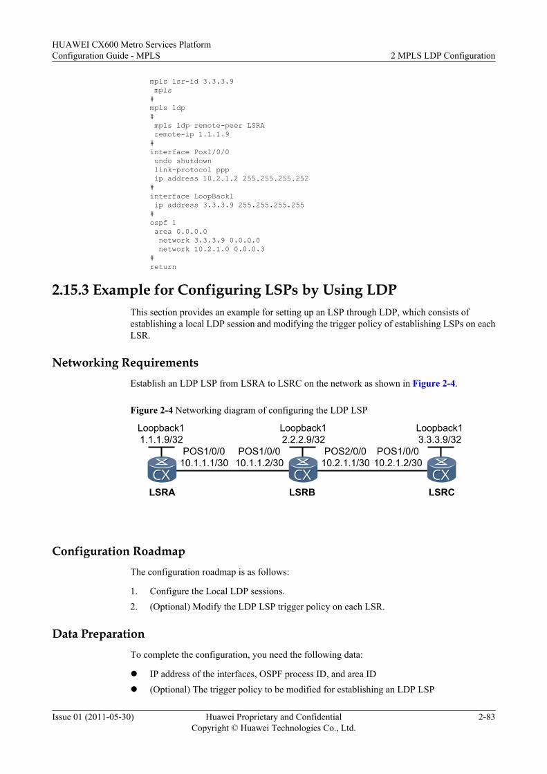
mpls lsr-id 3.3.3.9 mpls#mpls ldp# mpls ldp remote-peer LSRA remote-ip 1.1.1.9#interface Pos1/0/0 undo shutdown link-protocol ppp ip address 10.2.1.2 255.255.255.252#interface LoopBack1 ip address 3.3.3.9 255.255.255.255#ospf 1 area 0.0.0.0 network 3.3.3.9 0.0.0.0 network 10.2.1.0 0.0.0.3#return
2.15.3 Example for Configuring LSPs by Using LDPThis section provides an example for setting up an LSP through LDP, which consists ofestablishing a local LDP session and modifying the trigger policy of establishing LSPs on eachLSR.
Networking RequirementsEstablish an LDP LSP from LSRA to LSRC on the network as shown in Figure 2-4.
Figure 2-4 Networking diagram of configuring the LDP LSP
LSRB
POS1/0/010.1.1.1/30
POS1/0/010.1.1.2/30
LSRA LSRC
POS2/0/010.2.1.1/30
POS1/0/010.2.1.2/30
Loopback11.1.1.9/32
Loopback12.2.2.9/32
Loopback13.3.3.9/32
Configuration RoadmapThe configuration roadmap is as follows:
1. Configure the Local LDP sessions.2. (Optional) Modify the LDP LSP trigger policy on each LSR.
Data PreparationTo complete the configuration, you need the following data:
l IP address of the interfaces, OSPF process ID, and area IDl (Optional) The trigger policy to be modified for establishing an LDP LSP
HUAWEI CX600 Metro Services PlatformConfiguration Guide - MPLS 2 MPLS LDP Configuration
Issue 01 (2011-05-30) Huawei Proprietary and ConfidentialCopyright © Huawei Technologies Co., Ltd.
2-83
ProcedureStep 1 Configure the LDP LSP.
After the configuration in Example for Configuring LDP Sessions, all the LSRs triggers theestablishment of LDP LSPs according to the host route that is the default LDP LSP trigger policy.
Run the display mpls ldp lsp command on the LSRs, and you can view that all the host routestrigger the establishment of LDP LSPs.
Take the display on LSRA as an example.
LDP LSP Information ------------------------------------------------------------------------------- DestAddress/Mask In/OutLabel UpstreamPeer NextHop OutInterface ------------------------------------------------------------------------------- 1.1.1.9/32 3/NULL 2.2.2.9 127.0.0.1 InLoop0 *1.1.1.9/32 Liberal 2.2.2.9/32 NULL/3 - 10.1.1.2 Pos1/0/0 2.2.2.9/32 1024/3 2.2.2.9 10.1.1.2 Pos1/0/0 3.3.3.9/32 NULL/1025 - 10.1.1.2 Pos1/0/0 3.3.3.9/32 1025/1025 2.2.2.9 10.1.1.2 Pos1/0/0 ------------------------------------------------------------------------------- TOTAL: 5 Normal LSP(s) Found. TOTAL: 1 Liberal LSP(s) Found. TOTAL: 0 Frr LSP(s) Found. A '*' before an LSP means the LSP is not established A '*' before a Label means the USCB or DSCB is stale A '*' before a UpstreamPeer means the session is in GR state A '*' before a NextHop means the LSP is FRR LSP
NOTE
Usually, the default trigger policy is used. That is, the establishment of an LDP LSP is triggered by a hostroute. You can perform the following procedures to modify the LDP LSP trigger policy according to yourdemands.
Step 2 (Optional) Modify the LDP LSP trigger policy.
Configure the conditions of triggering LSPs as all on LSRs. All the static routes and IGP entriesthen can trigger the establishment of LSPs.
# Configure LSRA.
[LSRA] mpls[LSRA-mpls] lsp-trigger all[LSRA-mpls] quit
# Configure LSRB.
[LSRB] mpls[LSRB-mpls] lsp-trigger all[LSRB-mpls] quit
# Configure LSRC.
[LSRC] mpls[LSRC-mpls] lsp-trigger all[LSRC-mpls] quit
Step 3 Verify the configuration.
After the preceding configuration, run the display mpls ldp lsp command on each LSR, andyou can view information about the LDP LSP.
Take the display on LSRA as an example.
[LSRA] display mpls ldp lsp
2 MPLS LDP ConfigurationHUAWEI CX600 Metro Services Platform
Configuration Guide - MPLS
2-84 Huawei Proprietary and ConfidentialCopyright © Huawei Technologies Co., Ltd.
Issue 01 (2011-05-30)
LDP LSP Information ------------------------------------------------------------------------------- DestAddress/Mask In/OutLabel UpstreamPeer NextHop OutInterface ------------------------------------------------------------------------------- 1.1.1.9/32 3/NULL 2.2.2.9 127.0.0.1 InLoop0 *1.1.1.9/32 Liberal 2.2.2.9/32 NULL/3 - 10.1.1.2 Pos1/0/0 2.2.2.9/32 1024/3 2.2.2.9 10.1.1.2 Pos1/0/0 3.3.3.9/32 NULL/1025 - 10.1.1.2 Pos1/0/0 3.3.3.9/32 1025/1025 2.2.2.9 10.1.1.2 Pos1/0/0 10.1.1.0/30 3/NULL 2.2.2.9 10.1.1.1 Pos1/0/0 *10.1.1.0/30 Liberal 10.1.2.0/30 NULL/3 - 10.1.1.2 Pos1/0/0 10.1.2.0/30 1026/3 2.2.2.9 10.1.1.2 Pos1/0/0 ------------------------------------------------------------------------------- TOTAL: 8 Normal LSP(s) Found. TOTAL: 2 Liberal LSP(s) Found. TOTAL: 0 Frr LSP(s) Found. A '*' before an LSP means the LSP is not established A '*' before a Label means the USCB or DSCB is stale A '*' before a UpstreamPeer means the session is in GR state A '*' before a NextHop means the LSP is FRR LSP
----End
Configuration Filesl Configuration file of LSRA
# sysname LSRA# mpls lsr-id 1.1.1.9 mpls lsp-trigger all#mpls ldp#interface Pos1/0/0 undo shutdown link-protocol ppp ip address 10.1.1.1 255.255.255.252 mpls mpls ldp#interface LoopBack1 ip address 1.1.1.9 255.255.255.255#ospf 1 area 0.0.0.0 network 1.1.1.9 0.0.0.0 network 10.1.1.0 0.0.0.3#return
l Configuration file of LSRB# sysname LSRB# mpls lsr-id 2.2.2.9 mpls lsp-trigger all#mpls ldp#interface Pos1/0/0 undo shutdown link-protocol ppp ip address 10.1.1.2 255.255.255.252
HUAWEI CX600 Metro Services PlatformConfiguration Guide - MPLS 2 MPLS LDP Configuration
Issue 01 (2011-05-30) Huawei Proprietary and ConfidentialCopyright © Huawei Technologies Co., Ltd.
2-85
mpls mpls ldp#interface Pos2/0/0 undo shutdown link-protocol ppp ip address 10.2.1.1 255.255.255.252 mpls mpls ldp#interface LoopBack1 ip address 2.2.2.9 255.255.255.255#ospf 1 area 0.0.0.0 network 2.2.2.9 0.0.0.0 network 10.1.1.0 0.0.0.3 network 10.2.1.0 0.0.0.3#return
l Configuration file of LSRC# sysname LSRC# mpls lsr-id 3.3.3.9 mpls lsp-trigger all#mpls ldp#interface Pos1/0/0 undo shutdown link-protocol ppp ip address 10.2.1.2 255.255.255.252 mpls mpls ldp#interface LoopBack1 ip address 3.3.3.9 255.255.255.255#ospf 1 area 0.0.0.0 network 3.3.3.9 0.0.0.0 network 10.2.1.0 0.0.0.3#return
2.15.4 Example for Configuring LDP to Automatically Trigger aRequest in DoD Mode
This section provides an example for configuring LDP to automatically trigger a request in DoDmode, which consists of enabling global MPLS and MPLS LDP and configuring the labeladvertisement mode as DoD.
Networking Requirements
As shown in Figure 2-5, LSR A and LSR D are at the edge of a network. To set up a PW, aremote LDP session must be set up between LSR A and LSR D to set up a public network tunnel.As the network is of large scale, to save the network resources, you need to configure LDP toautomatically trigger a request to a downstream node for a label mapping message associatedwith a remote LDP peer in DoD mode. In this manner, you can reduce unnecessary IP and MPLSentries.
2 MPLS LDP ConfigurationHUAWEI CX600 Metro Services Platform
Configuration Guide - MPLS
2-86 Huawei Proprietary and ConfidentialCopyright © Huawei Technologies Co., Ltd.
Issue 01 (2011-05-30)
Figure 2-5 Networking diagram of configuring LDP to automatically trigger the request in DoDmode
LSRB
POS1/0/010.1.1.1/24
POS1/0/010.1.1.2/24LSRA LSRC
POS1/0/110.1.2.1/24
Loopback01.1.1.1/32
Loopback02.2.2.2/32
Loopback03.3.3.3/32
POS1/0/010.1.3.2/24LSRD
POS1/0/010.1.2.2/24
POS1/0/110.1.3.1/24
Loopback04.4.4.4/32
Configuration RoadmapThe configuration roadmap is as follows:
1. Assign an IP address to each interface of each node and configure the loopback addressthat is used as the LSR ID.
2. Configure basic IS-IS functions on each backbone network device and a static route to theneighbor of each edge device.
3. Enable global and interface-based MPLS and MPLS LDP on each node.4. Configure the DoD label distribution mode.5. Configure LDP extension for inter-area LSP.6. Configure a remote LDP session and enable the function of automatically triggering a
request to a downstream node for a label mapping message associated with a remote LDPpeer in DoD mode.
Data PreparationTo complete the configuration, you need the following data:
l IP address of an interface on each node as shown in Figure 2-5l IS-IS level on each node
Procedure
Step 1 Assign an IP address to each interface of each node and configure the loopback address that isused as the LSR ID.
As shown in Figure 2-5, configure an IP address and mask for each interface including theloopback interface. The configuration details are not mentioned here.
Step 2 Configure basic IS-IS functions on each backbone network device and a static route to theneighbor of each edge device.
# Configure basic IS-IS function on LSR B.
<LSRB> system-view[LSRB] isis 1[LSRB-isis-1] network-entity 10.0000.0000.0001.00[LSRB-isis-1] quit[LSRB] interface pos 1/0/1[LSRB-Pos1/0/1] isis enable 1
HUAWEI CX600 Metro Services PlatformConfiguration Guide - MPLS 2 MPLS LDP Configuration
Issue 01 (2011-05-30) Huawei Proprietary and ConfidentialCopyright © Huawei Technologies Co., Ltd.
2-87
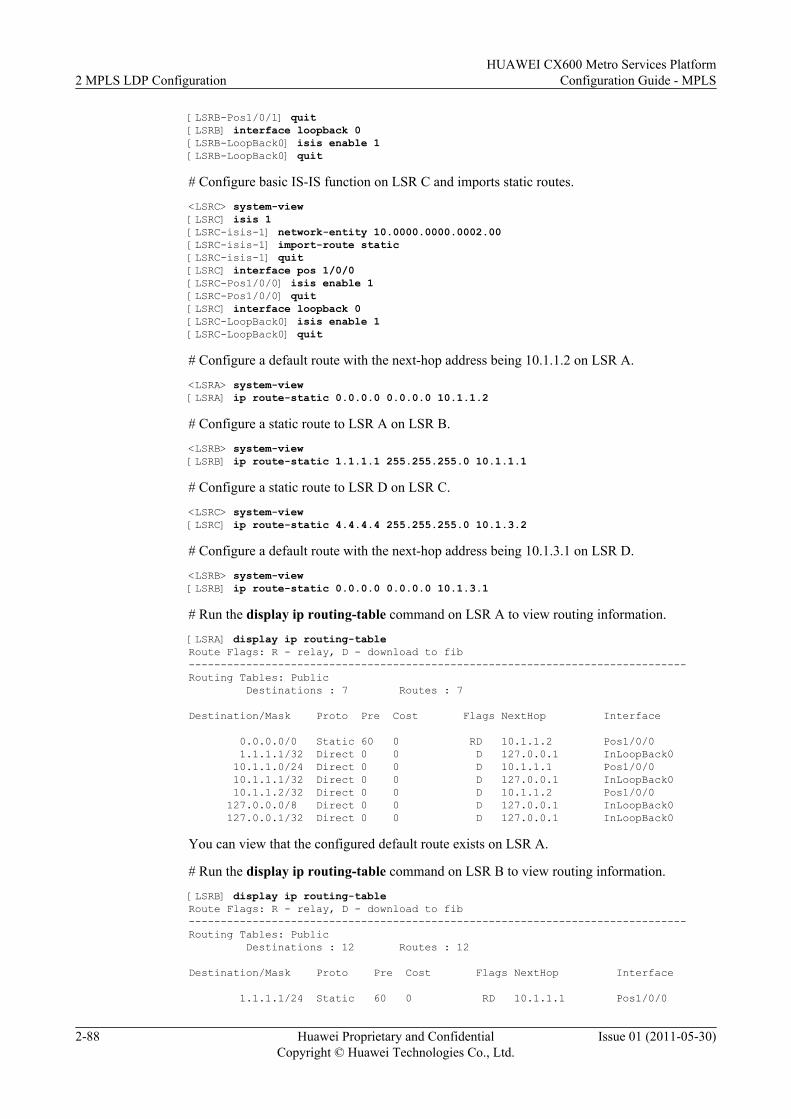
[LSRB-Pos1/0/1] quit[LSRB] interface loopback 0[LSRB-LoopBack0] isis enable 1[LSRB-LoopBack0] quit
# Configure basic IS-IS function on LSR C and imports static routes.
<LSRC> system-view[LSRC] isis 1[LSRC-isis-1] network-entity 10.0000.0000.0002.00[LSRC-isis-1] import-route static[LSRC-isis-1] quit[LSRC] interface pos 1/0/0[LSRC-Pos1/0/0] isis enable 1[LSRC-Pos1/0/0] quit[LSRC] interface loopback 0[LSRC-LoopBack0] isis enable 1[LSRC-LoopBack0] quit
# Configure a default route with the next-hop address being 10.1.1.2 on LSR A.
<LSRA> system-view[LSRA] ip route-static 0.0.0.0 0.0.0.0 10.1.1.2
# Configure a static route to LSR A on LSR B.
<LSRB> system-view[LSRB] ip route-static 1.1.1.1 255.255.255.0 10.1.1.1
# Configure a static route to LSR D on LSR C.
<LSRC> system-view[LSRC] ip route-static 4.4.4.4 255.255.255.0 10.1.3.2
# Configure a default route with the next-hop address being 10.1.3.1 on LSR D.
<LSRB> system-view[LSRB] ip route-static 0.0.0.0 0.0.0.0 10.1.3.1
# Run the display ip routing-table command on LSR A to view routing information.
[LSRA] display ip routing-tableRoute Flags: R - relay, D - download to fib------------------------------------------------------------------------------Routing Tables: Public Destinations : 7 Routes : 7
Destination/Mask Proto Pre Cost Flags NextHop Interface
0.0.0.0/0 Static 60 0 RD 10.1.1.2 Pos1/0/0 1.1.1.1/32 Direct 0 0 D 127.0.0.1 InLoopBack0 10.1.1.0/24 Direct 0 0 D 10.1.1.1 Pos1/0/0 10.1.1.1/32 Direct 0 0 D 127.0.0.1 InLoopBack0 10.1.1.2/32 Direct 0 0 D 10.1.1.2 Pos1/0/0 127.0.0.0/8 Direct 0 0 D 127.0.0.1 InLoopBack0 127.0.0.1/32 Direct 0 0 D 127.0.0.1 InLoopBack0
You can view that the configured default route exists on LSR A.
# Run the display ip routing-table command on LSR B to view routing information.
[LSRB] display ip routing-tableRoute Flags: R - relay, D - download to fib------------------------------------------------------------------------------Routing Tables: Public Destinations : 12 Routes : 12
Destination/Mask Proto Pre Cost Flags NextHop Interface
1.1.1.1/24 Static 60 0 RD 10.1.1.1 Pos1/0/0
2 MPLS LDP ConfigurationHUAWEI CX600 Metro Services Platform
Configuration Guide - MPLS
2-88 Huawei Proprietary and ConfidentialCopyright © Huawei Technologies Co., Ltd.
Issue 01 (2011-05-30)
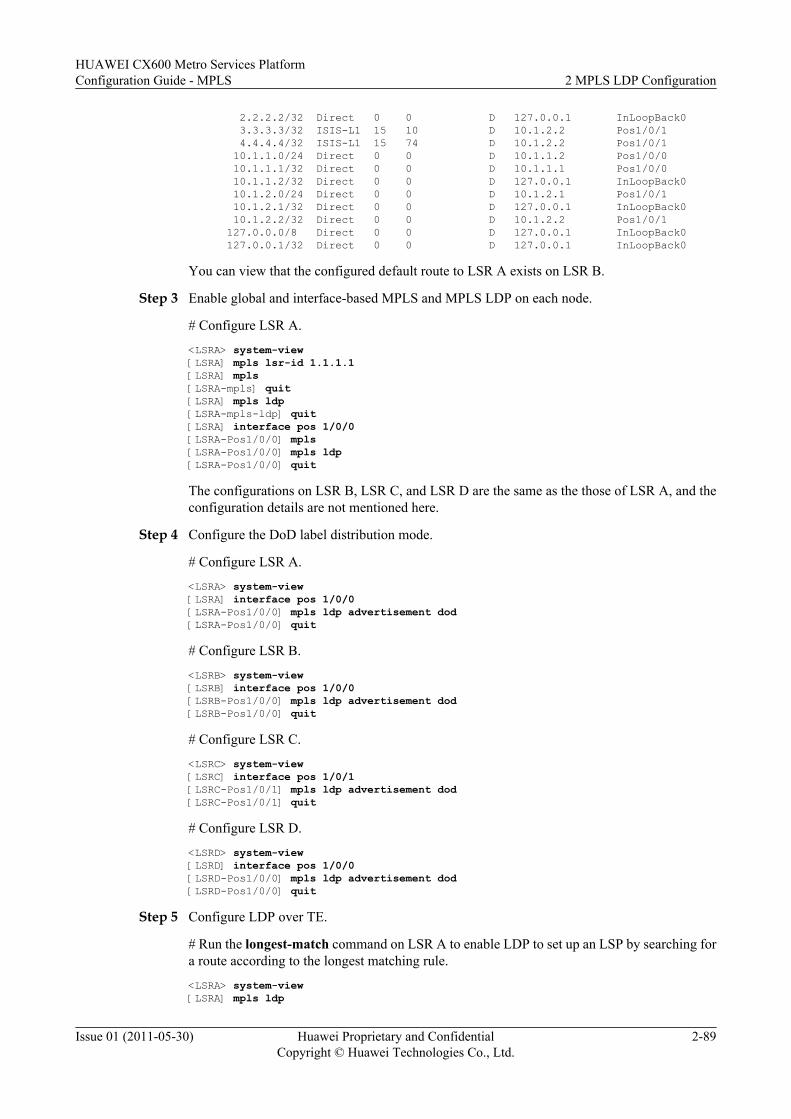
2.2.2.2/32 Direct 0 0 D 127.0.0.1 InLoopBack0 3.3.3.3/32 ISIS-L1 15 10 D 10.1.2.2 Pos1/0/1 4.4.4.4/32 ISIS-L1 15 74 D 10.1.2.2 Pos1/0/1 10.1.1.0/24 Direct 0 0 D 10.1.1.2 Pos1/0/0 10.1.1.1/32 Direct 0 0 D 10.1.1.1 Pos1/0/0 10.1.1.2/32 Direct 0 0 D 127.0.0.1 InLoopBack0 10.1.2.0/24 Direct 0 0 D 10.1.2.1 Pos1/0/1 10.1.2.1/32 Direct 0 0 D 127.0.0.1 InLoopBack0 10.1.2.2/32 Direct 0 0 D 10.1.2.2 Pos1/0/1 127.0.0.0/8 Direct 0 0 D 127.0.0.1 InLoopBack0 127.0.0.1/32 Direct 0 0 D 127.0.0.1 InLoopBack0
You can view that the configured default route to LSR A exists on LSR B.
Step 3 Enable global and interface-based MPLS and MPLS LDP on each node.
# Configure LSR A.
<LSRA> system-view[LSRA] mpls lsr-id 1.1.1.1[LSRA] mpls[LSRA-mpls] quit[LSRA] mpls ldp[LSRA-mpls-ldp] quit[LSRA] interface pos 1/0/0[LSRA-Pos1/0/0] mpls[LSRA-Pos1/0/0] mpls ldp[LSRA-Pos1/0/0] quit
The configurations on LSR B, LSR C, and LSR D are the same as the those of LSR A, and theconfiguration details are not mentioned here.
Step 4 Configure the DoD label distribution mode.
# Configure LSR A.
<LSRA> system-view[LSRA] interface pos 1/0/0[LSRA-Pos1/0/0] mpls ldp advertisement dod[LSRA-Pos1/0/0] quit
# Configure LSR B.
<LSRB> system-view[LSRB] interface pos 1/0/0[LSRB-Pos1/0/0] mpls ldp advertisement dod[LSRB-Pos1/0/0] quit
# Configure LSR C.
<LSRC> system-view[LSRC] interface pos 1/0/1[LSRC-Pos1/0/1] mpls ldp advertisement dod[LSRC-Pos1/0/1] quit
# Configure LSR D.
<LSRD> system-view[LSRD] interface pos 1/0/0[LSRD-Pos1/0/0] mpls ldp advertisement dod[LSRD-Pos1/0/0] quit
Step 5 Configure LDP over TE.
# Run the longest-match command on LSR A to enable LDP to set up an LSP by searching fora route according to the longest matching rule.
<LSRA> system-view[LSRA] mpls ldp
HUAWEI CX600 Metro Services PlatformConfiguration Guide - MPLS 2 MPLS LDP Configuration
Issue 01 (2011-05-30) Huawei Proprietary and ConfidentialCopyright © Huawei Technologies Co., Ltd.
2-89
[LSRA-mpls-ldp] longest-match[LSRA-mpls-ldp] quit
# Run the longest-match command on LSR D to enable LDP to set up an LSP by searching fora route according to the longest matching rule.
<LSRD> system-view[LSRD] mpls ldp[LSRD-mpls-ldp] longest-match[LSRD-mpls-ldp] quit
Step 6 Configure a remote LDP session and enable the function of automatically triggering a requestto a downstream node for a label mapping message associated with a remote LDP peer in DoDmode.
# Configure LSR A.
<LSRA> system-view[LSRA] mpls ldp remote-peer lsrd[LSRA-mpls-ldp-remote-lsrd] remote-ip 4.4.4.4[LSRA-mpls-ldp-remote-lsrd] remote-ip auto-dod-request[LSRA-mpls-ldp-remote-lsrd] quit
# Configure LSR D.
<LSRD> system-view[LSRD] mpls ldp remote-peer lsra[LSRD-mpls-ldp-remote-lsra] remote-ip 1.1.1.1[LSRD-mpls-ldp-remote-lsra] remote-ip auto-dod-request[LSRD-mpls-ldp-remote-lsra] quit
Step 7 Verify the configuration.
# After the preceding configuration, run the display ip routing-table 4.4.4.4 command on LSRA to view routing information.
<LSRA> display ip routing-table 4.4.4.4Route Flags: R - relay, D - download to fib------------------------------------------------------------------------------Routing Table : PublicSummary Count : 1Destination/Mask Proto Pre Cost Flags NextHop Interface
0.0.0.0/0 Static 60 0 RD 10.1.1.2 Pos1/0/0
You can view that only a default route exists and no exact route to 4.4.4.4 exists in the routingtable.
# Run the display mpls ldp lsp command on LSR A to view information about the establishedLSPs.
<LSRA> display mpls ldp lsp
LDP LSP Information ------------------------------------------------------------------------------- DestAddress/Mask In/OutLabel UpstreamPeer NextHop OutInterface ------------------------------------------------------------------------------- 4.4.4.4/32 NULL/1026 - 10.1.1.2 Pos1/0/0 ------------------------------------------------------------------------------- TOTAL: 1 Normal LSP(s) Found. TOTAL: 0 Liberal LSP(s) Found. TOTAL: 0 Frr LSP(s) Found. A '*' before an LSP means the LSP is not established A '*' before a Label means the USCB or DSCB is stale A '*' before a UpstreamPeer means the session is in GR state A '*' before a NextHop means the LSP is FRR LSP
2 MPLS LDP ConfigurationHUAWEI CX600 Metro Services Platform
Configuration Guide - MPLS
2-90 Huawei Proprietary and ConfidentialCopyright © Huawei Technologies Co., Ltd.
Issue 01 (2011-05-30)
You can view that an LSP destined for 4.4.4.4 is set up. It indicates that LSR A automaticallyrequests LSR B for a label mapping message associated with the destination 4.4.4.4 and thusLSP can be set up.
# Run the display tunnel-info all command on LSR A to view information about the establishedLSPs.
<LSRA> display tunnel-info all * -> Allocated VC TokenTunnel ID Type Destination Token----------------------------------------------------------------------0x1000 lsp 4.4.4.4 0
You can view that the LSP from LSR A to LSR D is set up.
----End
Configuration Filesl Configuration file of LSR A
# sysname LSRA# mpls lsr-id 1.1.1.1 mpls#mpls ldp longest-match## mpls ldp remote-peer lsrd remote-ip 4.4.4.4 undo remote-ip pwe3 remote-ip auto-dod-request#interface Pos1/0/0 link-protocol ppp ip address 10.1.1.1 255.255.255.0 mpls mpls ldp mpls ldp advertisement dod#interface NULL0#interface LoopBack0 ip address 1.1.1.1 255.255.255.255# ip route-static 0.0.0.0 0.0.0.0 10.1.1.2#return
l Configuration file of LSR B# sysname LSRB# mpls lsr-id 2.2.2.2 mpls#mpls ldp##isis 1 network-entity 10.0000.0000.0001.00#interface Pos1/0/0 link-protocol ppp
HUAWEI CX600 Metro Services PlatformConfiguration Guide - MPLS 2 MPLS LDP Configuration
Issue 01 (2011-05-30) Huawei Proprietary and ConfidentialCopyright © Huawei Technologies Co., Ltd.
2-91
ip address 10.1.1.2 255.255.255.0 mpls mpls ldp mpls ldp advertisement dod#interface Pos1/0/1 link-protocol ppp ip address 10.1.2.1 255.255.255.0 isis enable 1 mpls mpls ldp#interface NULL0#interface LoopBack0 ip address 2.2.2.2 255.255.255.255 isis enable 1# ip route-static 1.1.1.1 255.255.255.0 10.1.1.1#return
l Configuration file of LSR C# sysname LSRC# mpls lsr-id 3.3.3.3 mpls#mpls ldp##isis 1 network-entity 10.0000.0000.0002.00 import-route static#interface Pos1/0/0 link-protocol ppp ip address 10.1.2.2 255.255.255.0 isis enable 1 mpls mpls ldp#interface Pos1/0/1 link-protocol ppp ip address 10.1.3.1 255.255.255.0 mpls mpls ldp mpls ldp advertisement dod#interface NULL0#interface LoopBack0 ip address 3.3.3.3 255.255.255.255 isis enable 1# ip route-static 4.4.4.0 255.255.255.0 10.1.3.2#return
l Configuration file of LSR D# sysname LSRD# mpls lsr-id 4.4.4.4 mpls#mpls ldp longest-match#
2 MPLS LDP ConfigurationHUAWEI CX600 Metro Services Platform
Configuration Guide - MPLS
2-92 Huawei Proprietary and ConfidentialCopyright © Huawei Technologies Co., Ltd.
Issue 01 (2011-05-30)
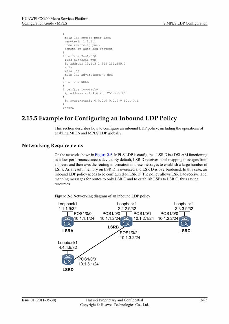
# mpls ldp remote-peer lsra remote-ip 1.1.1.1 undo remote-ip pwe3 remote-ip auto-dod-request#interface Pos1/0/0 link-protocol ppp ip address 10.1.3.2 255.255.255.0 mpls mpls ldp mpls ldp advertisement dod#interface NULL0#interface LoopBack0 ip address 4.4.4.4 255.255.255.255# ip route-static 0.0.0.0 0.0.0.0 10.1.3.1#return
2.15.5 Example for Configuring an Inbound LDP PolicyThis section describes how to configure an inbound LDP policy, including the operations ofenabling MPLS and MPLS LDP globally.
Networking Requirements
On the network shown in Figure 2-6, MPLS LDP is configured. LSR D is a DSLAM functioningas a low-performance access device. By default, LSR D receives label mapping messages fromall peers and then uses the routing information in these messages to establish a large number ofLSPs. As a result, memory on LSR D is overused and LSR D is overburdened. In this case, aninbound LDP policy needs to be configured on LSR D. The policy allows LSR D to receive labelmapping messages for routes to only LSR C and to establish LSPs to LSR C, thus savingresources.
Figure 2-6 Networking diagram of an inbound LDP policy
LSRB
POS1/0/010.1.1.1/24
POS1/0/010.1.1.2/24
LSRA LSRC
POS1/0/110.1.2.1/24
POS1/0/010.1.2.2/24
Loopback11.1.1.9/32
Loopback12.2.2.9/32
Loopback13.3.3.9/32
LSRD
Loopback14.4.4.9/32
POS1/0/010.1.3.1/24
POS1/0/210.1.3.2/24
HUAWEI CX600 Metro Services PlatformConfiguration Guide - MPLS 2 MPLS LDP Configuration
Issue 01 (2011-05-30) Huawei Proprietary and ConfidentialCopyright © Huawei Technologies Co., Ltd.
2-93
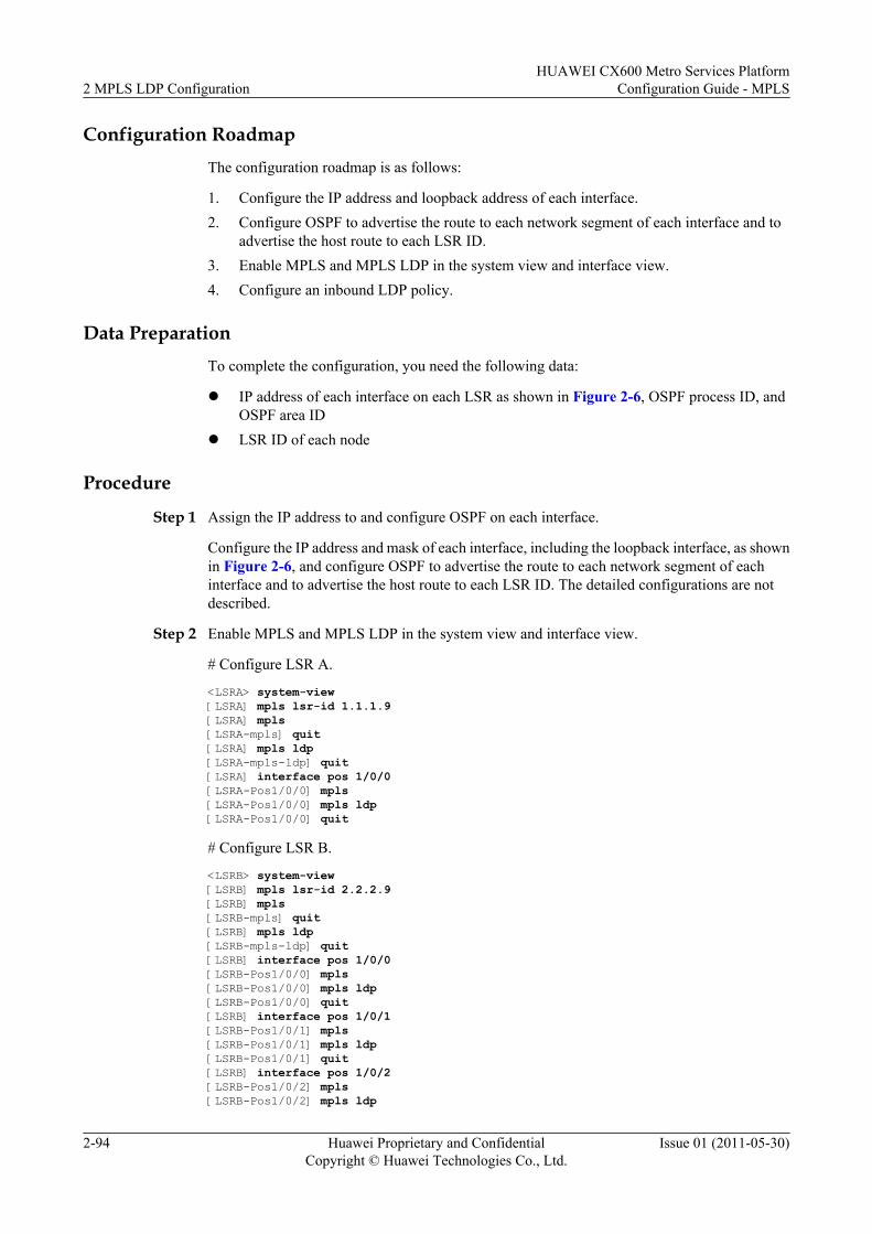
Configuration RoadmapThe configuration roadmap is as follows:
1. Configure the IP address and loopback address of each interface.2. Configure OSPF to advertise the route to each network segment of each interface and to
advertise the host route to each LSR ID.3. Enable MPLS and MPLS LDP in the system view and interface view.4. Configure an inbound LDP policy.
Data PreparationTo complete the configuration, you need the following data:
l IP address of each interface on each LSR as shown in Figure 2-6, OSPF process ID, andOSPF area ID
l LSR ID of each node
Procedure
Step 1 Assign the IP address to and configure OSPF on each interface.
Configure the IP address and mask of each interface, including the loopback interface, as shownin Figure 2-6, and configure OSPF to advertise the route to each network segment of eachinterface and to advertise the host route to each LSR ID. The detailed configurations are notdescribed.
Step 2 Enable MPLS and MPLS LDP in the system view and interface view.
# Configure LSR A.
<LSRA> system-view [LSRA] mpls lsr-id 1.1.1.9[LSRA] mpls[LSRA-mpls] quit[LSRA] mpls ldp[LSRA-mpls-ldp] quit[LSRA] interface pos 1/0/0[LSRA-Pos1/0/0] mpls[LSRA-Pos1/0/0] mpls ldp[LSRA-Pos1/0/0] quit
# Configure LSR B.
<LSRB> system-view [LSRB] mpls lsr-id 2.2.2.9[LSRB] mpls[LSRB-mpls] quit[LSRB] mpls ldp[LSRB-mpls-ldp] quit[LSRB] interface pos 1/0/0[LSRB-Pos1/0/0] mpls[LSRB-Pos1/0/0] mpls ldp[LSRB-Pos1/0/0] quit[LSRB] interface pos 1/0/1[LSRB-Pos1/0/1] mpls[LSRB-Pos1/0/1] mpls ldp[LSRB-Pos1/0/1] quit[LSRB] interface pos 1/0/2[LSRB-Pos1/0/2] mpls[LSRB-Pos1/0/2] mpls ldp
2 MPLS LDP ConfigurationHUAWEI CX600 Metro Services Platform
Configuration Guide - MPLS
2-94 Huawei Proprietary and ConfidentialCopyright © Huawei Technologies Co., Ltd.
Issue 01 (2011-05-30)
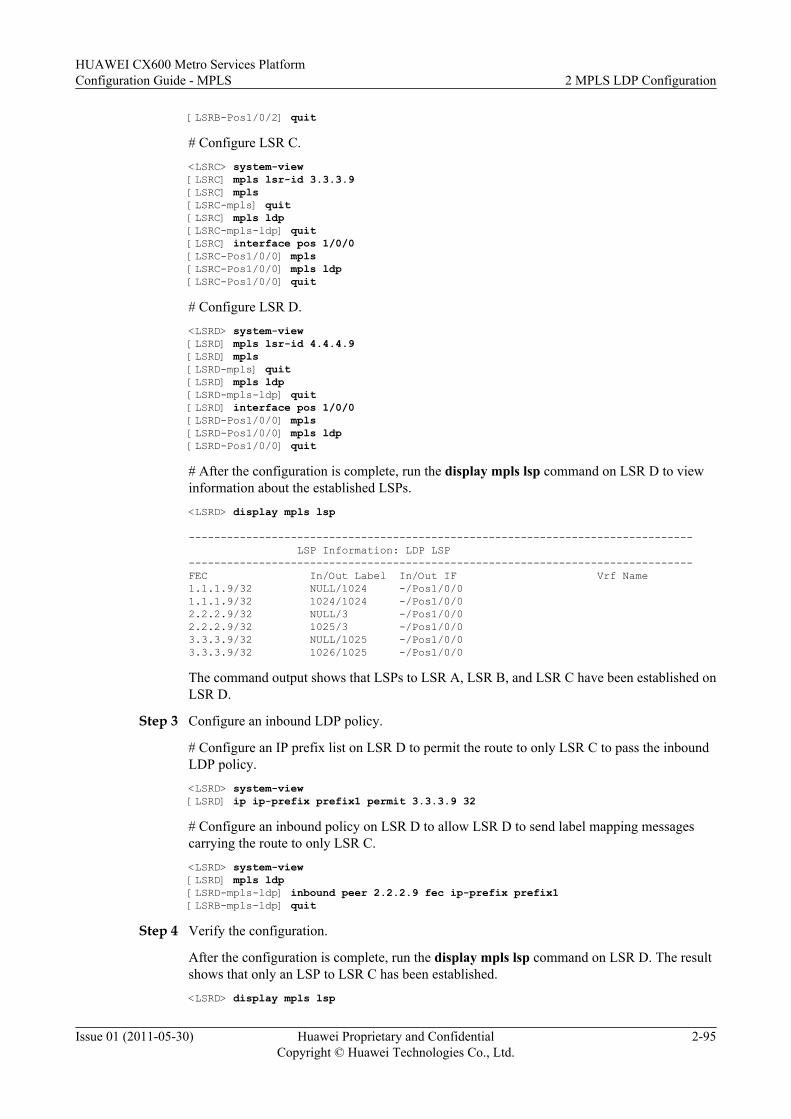
[LSRB-Pos1/0/2] quit
# Configure LSR C.<LSRC> system-view [LSRC] mpls lsr-id 3.3.3.9[LSRC] mpls[LSRC-mpls] quit[LSRC] mpls ldp[LSRC-mpls-ldp] quit[LSRC] interface pos 1/0/0[LSRC-Pos1/0/0] mpls[LSRC-Pos1/0/0] mpls ldp[LSRC-Pos1/0/0] quit
# Configure LSR D.<LSRD> system-view [LSRD] mpls lsr-id 4.4.4.9[LSRD] mpls[LSRD-mpls] quit[LSRD] mpls ldp[LSRD-mpls-ldp] quit[LSRD] interface pos 1/0/0[LSRD-Pos1/0/0] mpls[LSRD-Pos1/0/0] mpls ldp[LSRD-Pos1/0/0] quit
# After the configuration is complete, run the display mpls lsp command on LSR D to viewinformation about the established LSPs.<LSRD> display mpls lsp
------------------------------------------------------------------------------- LSP Information: LDP LSP-------------------------------------------------------------------------------FEC In/Out Label In/Out IF Vrf Name1.1.1.9/32 NULL/1024 -/Pos1/0/01.1.1.9/32 1024/1024 -/Pos1/0/02.2.2.9/32 NULL/3 -/Pos1/0/02.2.2.9/32 1025/3 -/Pos1/0/03.3.3.9/32 NULL/1025 -/Pos1/0/03.3.3.9/32 1026/1025 -/Pos1/0/0
The command output shows that LSPs to LSR A, LSR B, and LSR C have been established onLSR D.
Step 3 Configure an inbound LDP policy.
# Configure an IP prefix list on LSR D to permit the route to only LSR C to pass the inboundLDP policy.<LSRD> system-view [LSRD] ip ip-prefix prefix1 permit 3.3.3.9 32
# Configure an inbound policy on LSR D to allow LSR D to send label mapping messagescarrying the route to only LSR C.<LSRD> system-view [LSRD] mpls ldp[LSRD-mpls-ldp] inbound peer 2.2.2.9 fec ip-prefix prefix1[LSRB-mpls-ldp] quit
Step 4 Verify the configuration.
After the configuration is complete, run the display mpls lsp command on LSR D. The resultshows that only an LSP to LSR C has been established.<LSRD> display mpls lsp
HUAWEI CX600 Metro Services PlatformConfiguration Guide - MPLS 2 MPLS LDP Configuration
Issue 01 (2011-05-30) Huawei Proprietary and ConfidentialCopyright © Huawei Technologies Co., Ltd.
2-95
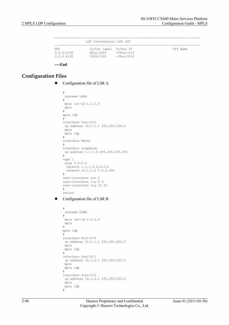
------------------------------------------------------------------------------- LSP Information: LDP LSP-------------------------------------------------------------------------------FEC In/Out Label In/Out IF Vrf Name3.3.3.9/32 NULL/1025 -/Pos1/0/03.3.3.9/32 1026/1025 -/Pos1/0/0
----End
Configuration Filesl Configuration file of LSR A
# sysname LSRA# mpls lsr-id 1.1.1.9 mpls#mpls ldp#interface Pos1/0/0 ip address 10.1.1.1 255.255.255.0 mpls mpls ldp#interface NULL0#interface LoopBack1 ip address 1.1.1.9 255.255.255.255#ospf 1 area 0.0.0.0 network 1.1.1.9 0.0.0.0 network 10.1.1.0 0.0.0.255#user-interface con 0user-interface vty 0 4user-interface vty 16 20#return
l Configuration file of LSR B
# sysname LSRB# mpls lsr-id 2.2.2.9 mpls#mpls ldp#interface Pos1/0/0 ip address 10.1.1.2 255.255.255.0 mpls mpls ldp#interface Pos1/0/1 ip address 10.1.2.1 255.255.255.0 mpls mpls ldp#interface Pos1/0/2 ip address 10.1.3.2 255.255.255.0 mpls mpls ldp#
2 MPLS LDP ConfigurationHUAWEI CX600 Metro Services Platform
Configuration Guide - MPLS
2-96 Huawei Proprietary and ConfidentialCopyright © Huawei Technologies Co., Ltd.
Issue 01 (2011-05-30)
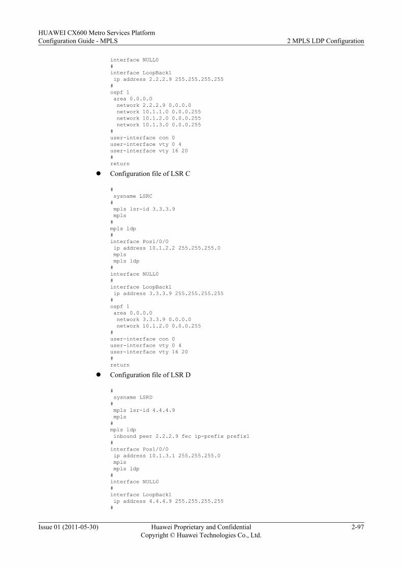
interface NULL0#interface LoopBack1 ip address 2.2.2.9 255.255.255.255#ospf 1 area 0.0.0.0 network 2.2.2.9 0.0.0.0 network 10.1.1.0 0.0.0.255 network 10.1.2.0 0.0.0.255 network 10.1.3.0 0.0.0.255#user-interface con 0user-interface vty 0 4user-interface vty 16 20#return
l Configuration file of LSR C
# sysname LSRC# mpls lsr-id 3.3.3.9 mpls#mpls ldp#interface Pos1/0/0 ip address 10.1.2.2 255.255.255.0 mpls mpls ldp#interface NULL0#interface LoopBack1 ip address 3.3.3.9 255.255.255.255#ospf 1 area 0.0.0.0 network 3.3.3.9 0.0.0.0 network 10.1.2.0 0.0.0.255#user-interface con 0user-interface vty 0 4user-interface vty 16 20#return
l Configuration file of LSR D
# sysname LSRD# mpls lsr-id 4.4.4.9 mpls#mpls ldp inbound peer 2.2.2.9 fec ip-prefix prefix1#interface Pos1/0/0 ip address 10.1.3.1 255.255.255.0 mpls mpls ldp#interface NULL0#interface LoopBack1 ip address 4.4.4.9 255.255.255.255#
HUAWEI CX600 Metro Services PlatformConfiguration Guide - MPLS 2 MPLS LDP Configuration
Issue 01 (2011-05-30) Huawei Proprietary and ConfidentialCopyright © Huawei Technologies Co., Ltd.
2-97
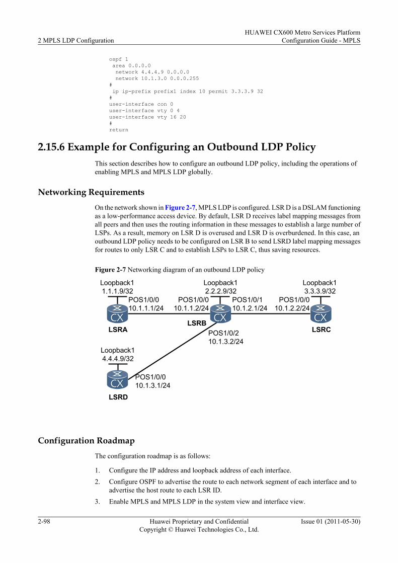
ospf 1 area 0.0.0.0 network 4.4.4.9 0.0.0.0 network 10.1.3.0 0.0.0.255# ip ip-prefix prefix1 index 10 permit 3.3.3.9 32#user-interface con 0user-interface vty 0 4user-interface vty 16 20#return
2.15.6 Example for Configuring an Outbound LDP PolicyThis section describes how to configure an outbound LDP policy, including the operations ofenabling MPLS and MPLS LDP globally.
Networking Requirements
On the network shown in Figure 2-7, MPLS LDP is configured. LSR D is a DSLAM functioningas a low-performance access device. By default, LSR D receives label mapping messages fromall peers and then uses the routing information in these messages to establish a large number ofLSPs. As a result, memory on LSR D is overused and LSR D is overburdened. In this case, anoutbound LDP policy needs to be configured on LSR B to send LSRD label mapping messagesfor routes to only LSR C and to establish LSPs to LSR C, thus saving resources.
Figure 2-7 Networking diagram of an outbound LDP policy
LSRB
POS1/0/010.1.1.1/24
POS1/0/010.1.1.2/24
LSRA LSRC
POS1/0/110.1.2.1/24
POS1/0/010.1.2.2/24
Loopback11.1.1.9/32
Loopback12.2.2.9/32
Loopback13.3.3.9/32
LSRD
Loopback14.4.4.9/32
POS1/0/010.1.3.1/24
POS1/0/210.1.3.2/24
Configuration Roadmap
The configuration roadmap is as follows:
1. Configure the IP address and loopback address of each interface.2. Configure OSPF to advertise the route to each network segment of each interface and to
advertise the host route to each LSR ID.3. Enable MPLS and MPLS LDP in the system view and interface view.
2 MPLS LDP ConfigurationHUAWEI CX600 Metro Services Platform
Configuration Guide - MPLS
2-98 Huawei Proprietary and ConfidentialCopyright © Huawei Technologies Co., Ltd.
Issue 01 (2011-05-30)
4. Configure an outbound LDP policy.
Data PreparationTo complete the configuration, you need the following data:
l IP address of each interface on each LSR as shown in Figure 2-7, OSPF process ID, andOSPF area ID
l LSR ID of each node
ProcedureStep 1 Assign the IP address to and configure OSPF on each interface.
Configure the IP address and mask of each interface, including the loopback interface, as shownin Figure 2-7, and configure OSPF to advertise the route to each network segment of eachinterface and to advertise the host route to each LSR ID. The detailed configurations are notdescribed.
Step 2 Enable MPLS and MPLS LDP in the system view and interface view.
# Configure LSR A.
<LSRA> system-view [LSRA] mpls lsr-id 1.1.1.9[LSRA] mpls[LSRA-mpls] quit[LSRA] mpls ldp[LSRA-mpls-ldp] quit[LSRA] interface pos 1/0/0[LSRA-Pos1/0/0] mpls[LSRA-Pos1/0/0] mpls ldp[LSRA-Pos1/0/0] quit
# Configure LSR B.
<LSRB> system-view [LSRB] mpls lsr-id 2.2.2.9[LSRB] mpls[LSRB-mpls] quit[LSRB] mpls ldp[LSRB-mpls-ldp] quit[LSRB] interface pos 1/0/0[LSRB-Pos1/0/0] mpls[LSRB-Pos1/0/0] mpls ldp[LSRB-Pos1/0/0] quit[LSRB] interface pos 1/0/1[LSRB-Pos1/0/1] mpls[LSRB-Pos1/0/1] mpls ldp[LSRB-Pos1/0/1] quit[LSRB] interface pos 1/0/2[LSRB-Pos1/0/2] mpls[LSRB-Pos1/0/2] mpls ldp[LSRB-Pos1/0/2] quit
# Configure LSR C.
<LSRC> system-view [LSRC] mpls lsr-id 3.3.3.9[LSRC] mpls[LSRC-mpls] quit[LSRC] mpls ldp[LSRC-mpls-ldp] quit[LSRC] interface pos 1/0/0[LSRC-Pos1/0/0] mpls
HUAWEI CX600 Metro Services PlatformConfiguration Guide - MPLS 2 MPLS LDP Configuration
Issue 01 (2011-05-30) Huawei Proprietary and ConfidentialCopyright © Huawei Technologies Co., Ltd.
2-99
[LSRC-Pos1/0/0] mpls ldp[LSRC-Pos1/0/0] quit
# Configure LSR D.
<LSRD> system-view [LSRD] mpls lsr-id 4.4.4.9[LSRD] mpls[LSRD-mpls] quit[LSRD] mpls ldp[LSRD-mpls-ldp] quit[LSRD] interface pos 1/0/0[LSRD-Pos1/0/0] mpls[LSRD-Pos1/0/0] mpls ldp[LSRD-Pos1/0/0] quit
# After the configuration is complete, run the display mpls lsp command on LSR D to viewinformation about the established LSPs.
<LSRD> display mpls lsp
------------------------------------------------------------------------------- LSP Information: LDP LSP-------------------------------------------------------------------------------FEC In/Out Label In/Out IF Vrf Name1.1.1.9/32 NULL/1024 -/Pos1/0/01.1.1.9/32 1024/1024 -/Pos1/0/02.2.2.9/32 NULL/3 -/Pos1/0/02.2.2.9/32 1025/3 -/Pos1/0/03.3.3.9/32 NULL/1025 -/Pos1/0/03.3.3.9/32 1026/1025 -/Pos1/0/0
The command output shows that LSPs to LSR A, LSR B, and LSR C have been established onLSR D.
Step 3 Configure an outbound LDP policy.
# Configure an IP prefix list on LSR B to permit the routes to LSR C to pass the outbound LDPpolicy.
<LSRB> system-view [LSRB] ip ip-prefix prefix1 permit 3.3.3.9 32
# Configure an outbound policy on LSR B to send LSR D label mapping messages carrying theroute to only LSR C.
<LSRB> system-view [LSRB] mpls ldp[LSRB-mpls-ldp] outbound peer 4.4.4.9 fec ip-prefix prefix1[LSRB-mpls-ldp] quit
Step 4 Verify the configuration.
After the configuration is complete, run the display mpls lsp command on LSR D. The resultshows that only an LSP to LSR C has been established.
<LSRD> display mpls lsp
------------------------------------------------------------------------------- LSP Information: LDP LSP-------------------------------------------------------------------------------FEC In/Out Label In/Out IF Vrf Name3.3.3.9/32 NULL/1025 -/Pos1/0/03.3.3.9/32 1026/1025 -/Pos1/0/0
----End
2 MPLS LDP ConfigurationHUAWEI CX600 Metro Services Platform
Configuration Guide - MPLS
2-100 Huawei Proprietary and ConfidentialCopyright © Huawei Technologies Co., Ltd.
Issue 01 (2011-05-30)
Configuration Filesl Configuration file of LSR A
# sysname LSRA# mpls lsr-id 1.1.1.9 mpls#mpls ldp#interface Pos1/0/0 ip address 10.1.1.1 255.255.255.0 mpls mpls ldp#interface NULL0#interface LoopBack1 ip address 1.1.1.9 255.255.255.255#ospf 1 area 0.0.0.0 network 1.1.1.9 0.0.0.0 network 10.1.1.0 0.0.0.255#user-interface con 0user-interface vty 0 4user-interface vty 16 20#return
l Configuration file of LSR B
# sysname LSRB# mpls lsr-id 2.2.2.9 mpls#mpls ldp outbound peer 4.4.4.9 fec ip-prefix prefix1#interface Pos1/0/0 ip address 10.1.1.2 255.255.255.0 mpls mpls ldp#interface Pos1/0/1 ip address 10.1.2.1 255.255.255.0 mpls mpls ldp#interface Pos1/0/2 ip address 10.1.3.2 255.255.255.0 mpls mpls ldp#interface NULL0#interface LoopBack1 ip address 2.2.2.9 255.255.255.255#ospf 1 area 0.0.0.0 network 2.2.2.9 0.0.0.0 network 10.1.1.0 0.0.0.255 network 10.1.2.0 0.0.0.255
HUAWEI CX600 Metro Services PlatformConfiguration Guide - MPLS 2 MPLS LDP Configuration
Issue 01 (2011-05-30) Huawei Proprietary and ConfidentialCopyright © Huawei Technologies Co., Ltd.
2-101
network 10.1.3.0 0.0.0.255# ip ip-prefix prefix1 index 10 permit 3.3.3.9 32#user-interface con 0user-interface vty 0 4user-interface vty 16 20#return
l Configuration file of LSR C
# sysname LSRC# mpls lsr-id 3.3.3.9 mpls#mpls ldp#interface Pos1/0/0 ip address 10.1.2.2 255.255.255.0 mpls mpls ldp#interface NULL0#interface LoopBack1 ip address 3.3.3.9 255.255.255.255#ospf 1 area 0.0.0.0 network 3.3.3.9 0.0.0.0 network 10.1.2.0 0.0.0.255#user-interface con 0user-interface vty 0 4user-interface vty 16 20#return
l Configuration file of LSR D
# sysname LSRD# mpls lsr-id 4.4.4.9 mpls#mpls ldp#interface Pos1/0/0 ip address 10.1.3.1 255.255.255.0 mpls mpls ldp#interface NULL0#interface LoopBack1 ip address 4.4.4.9 255.255.255.255#ospf 1 area 0.0.0.0 network 4.4.4.9 0.0.0.0 network 10.1.3.0 0.0.0.255#user-interface con 0user-interface vty 0 4user-interface vty 16 20
2 MPLS LDP ConfigurationHUAWEI CX600 Metro Services Platform
Configuration Guide - MPLS
2-102 Huawei Proprietary and ConfidentialCopyright © Huawei Technologies Co., Ltd.
Issue 01 (2011-05-30)
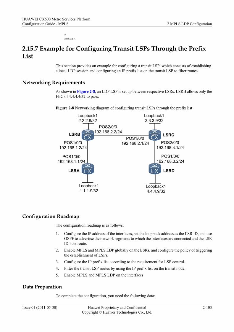
#return
2.15.7 Example for Configuring Transit LSPs Through the PrefixList
This section provides an example for configuring a transit LSP, which consists of establishinga local LDP session and configuring an IP prefix list on the transit LSP to filter routes.
Networking RequirementsAs shown in Figure 2-8, an LDP LSP is set up between respective LSRs. LSRB allows only theFEC of 4.4.4.4/32 to pass.
Figure 2-8 Networking diagram of configuring transit LSPs through the prefix list
LSRB
POS1/0/0192.168.1.1/24
POS1/0/0192.168.1.2/24
LSRA
LSRC
POS2/0/0192.168.2.2/24
Loopback11.1.1.9/32
Loopback12.2.2.9/32
Loopback13.3.3.9/32
POS1/0/0192.168.3.2/24
LSRD
POS1/0/0192.168.2.1/24 POS2/0/0
192.168.3.1/24
Loopback14.4.4.9/32
Configuration RoadmapThe configuration roadmap is as follows:
1. Configure the IP address of the interfaces, set the loopback address as the LSR ID, and useOSPF to advertise the network segments to which the interfaces are connected and the LSRID host route.
2. Enable MPLS and MPLS LDP globally on the LSRs, and configure the policy of triggeringthe establishment of LSPs.
3. Configure the IP prefix list according to the requirement for LSP control.4. Filter the transit LSP routes by using the IP prefix list on the transit node.5. Enable MPLS and MPLS LDP on the interfaces.
Data PreparationTo complete the configuration, you need the following data:
HUAWEI CX600 Metro Services PlatformConfiguration Guide - MPLS 2 MPLS LDP Configuration
Issue 01 (2011-05-30) Huawei Proprietary and ConfidentialCopyright © Huawei Technologies Co., Ltd.
2-103
l IP address of the interfaces, OSPF process ID, and area IDl Policy for triggering the establishment of LSPsl IP prefix list name, and the routes to be filtered on the transit node
Procedure
Step 1 Configure the IP address of the interfaces, and use OSPF to advertise the network segments thatthe interfaces are connected to and the LSR ID host route.
According to Figure 2-8, configure the IP address and the mask of the interfaces, including theloopback interface, and run OSPF. The configuration details are not mentioned here.
Step 2 Configure the IP prefix list on the transit.
# Configure the IP prefix list on the transit node LSRB. Only 4.4.4.4/32 of LSRD can be usedto establish the transit LSP.
[LSRB] ip ip-prefix FilterOnTransit permit 4.4.4.4 32
Step 3 Configure basic MPLS functions and MPLS LDP functions globally and on the interfaces.
# Configure LSRA.
[LSRA] mpls lsr-id 1.1.1.1[LSRA] mpls[LSRA-mpls] lsp-trigger all[LSRA-mpls] quit[LSRA] mpls ldp[LSRA-mpls-ldp] quit[LSRA] interface pos 1/0/0[LSRA-Pos1/0/0] mpls[LSRA-Pos1/0/0] mpls ldp[LSRA-Pos1/0/0] quit
# Configure LSRB.
[LSRB] mpls lsr-id 2.2.2.2[LSRB] mpls[LSRB-mpls] lsp-trigger all[LSRB-mpls] quit[LSRB] mpls ldp[LSRB-mpls-ldp] propagate mapping for ip-prefix FilterOnTransit[LSRB-mpls-ldp] quit[LSRB] interface pos 1/0/0[LSRB-Pos1/0/0] mpls[LSRB-Pos1/0/0] mpls ldp[LSRB-Pos1/0/0] quit[LSRB] interface pos 2/0/0[LSRB-Pos2/0/0] mpls[LSRB-Pos2/0/0] mpls ldp[LSRB-Pos2/0/0] quit
The configurations of LSRC and LSRD are similar to that of LSRA and LSRB, and theconfigurations are not mentioned here.
Step 4 Verify the configuration.
Run the display mpls ldp lsp command, and you can view the establishment of LSPs.
# Display the LDP LSP on LSRA.
[LSRA] display mpls ldp lsp
LDP LSP Information -------------------------------------------------------------------------------
2 MPLS LDP ConfigurationHUAWEI CX600 Metro Services Platform
Configuration Guide - MPLS
2-104 Huawei Proprietary and ConfidentialCopyright © Huawei Technologies Co., Ltd.
Issue 01 (2011-05-30)
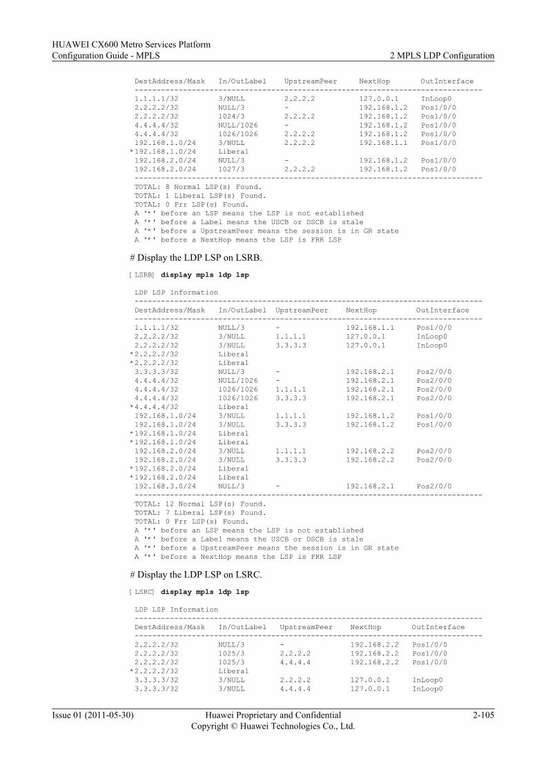
DestAddress/Mask In/OutLabel UpstreamPeer NextHop OutInterface ------------------------------------------------------------------------------- 1.1.1.1/32 3/NULL 2.2.2.2 127.0.0.1 InLoop0 2.2.2.2/32 NULL/3 - 192.168.1.2 Pos1/0/0 2.2.2.2/32 1024/3 2.2.2.2 192.168.1.2 Pos1/0/0 4.4.4.4/32 NULL/1026 - 192.168.1.2 Pos1/0/0 4.4.4.4/32 1026/1026 2.2.2.2 192.168.1.2 Pos1/0/0 192.168.1.0/24 3/NULL 2.2.2.2 192.168.1.1 Pos1/0/0 *192.168.1.0/24 Liberal 192.168.2.0/24 NULL/3 - 192.168.1.2 Pos1/0/0 192.168.2.0/24 1027/3 2.2.2.2 192.168.1.2 Pos1/0/0 ------------------------------------------------------------------------------- TOTAL: 8 Normal LSP(s) Found. TOTAL: 1 Liberal LSP(s) Found. TOTAL: 0 Frr LSP(s) Found. A '*' before an LSP means the LSP is not established A '*' before a Label means the USCB or DSCB is stale A '*' before a UpstreamPeer means the session is in GR state A '*' before a NextHop means the LSP is FRR LSP
# Display the LDP LSP on LSRB.
[LSRB] display mpls ldp lsp
LDP LSP Information ------------------------------------------------------------------------------- DestAddress/Mask In/OutLabel UpstreamPeer NextHop OutInterface ------------------------------------------------------------------------------- 1.1.1.1/32 NULL/3 - 192.168.1.1 Pos1/0/0 2.2.2.2/32 3/NULL 1.1.1.1 127.0.0.1 InLoop0 2.2.2.2/32 3/NULL 3.3.3.3 127.0.0.1 InLoop0*2.2.2.2/32 Liberal*2.2.2.2/32 Liberal 3.3.3.3/32 NULL/3 - 192.168.2.1 Pos2/0/0 4.4.4.4/32 NULL/1026 - 192.168.2.1 Pos2/0/0 4.4.4.4/32 1026/1026 1.1.1.1 192.168.2.1 Pos2/0/0 4.4.4.4/32 1026/1026 3.3.3.3 192.168.2.1 Pos2/0/0*4.4.4.4/32 Liberal 192.168.1.0/24 3/NULL 1.1.1.1 192.168.1.2 Pos1/0/0 192.168.1.0/24 3/NULL 3.3.3.3 192.168.1.2 Pos1/0/0*192.168.1.0/24 Liberal*192.168.1.0/24 Liberal 192.168.2.0/24 3/NULL 1.1.1.1 192.168.2.2 Pos2/0/0 192.168.2.0/24 3/NULL 3.3.3.3 192.168.2.2 Pos2/0/0*192.168.2.0/24 Liberal*192.168.2.0/24 Liberal 192.168.3.0/24 NULL/3 - 192.168.2.1 Pos2/0/0 ------------------------------------------------------------------------------- TOTAL: 12 Normal LSP(s) Found. TOTAL: 7 Liberal LSP(s) Found. TOTAL: 0 Frr LSP(s) Found. A '*' before an LSP means the LSP is not established A '*' before a Label means the USCB or DSCB is stale A '*' before a UpstreamPeer means the session is in GR state A '*' before a NextHop means the LSP is FRR LSP
# Display the LDP LSP on LSRC.
[LSRC] display mpls ldp lsp
LDP LSP Information ------------------------------------------------------------------------------- DestAddress/Mask In/OutLabel UpstreamPeer NextHop OutInterface ------------------------------------------------------------------------------- 2.2.2.2/32 NULL/3 - 192.168.2.2 Pos1/0/0 2.2.2.2/32 1025/3 2.2.2.2 192.168.2.2 Pos1/0/0 2.2.2.2/32 1025/3 4.4.4.4 192.168.2.2 Pos1/0/0*2.2.2.2/32 Liberal 3.3.3.3/32 3/NULL 2.2.2.2 127.0.0.1 InLoop0 3.3.3.3/32 3/NULL 4.4.4.4 127.0.0.1 InLoop0
HUAWEI CX600 Metro Services PlatformConfiguration Guide - MPLS 2 MPLS LDP Configuration
Issue 01 (2011-05-30) Huawei Proprietary and ConfidentialCopyright © Huawei Technologies Co., Ltd.
2-105
*3.3.3.3/32 Liberal 4.4.4.4/32 NULL/3 - 192.168.3.2 Pos2/0/0 4.4.4.4/32 1026/3 2.2.2.2 192.168.3.2 Pos2/0/0 4.4.4.4/32 1026/3 4.4.4.4 192.168.3.2 Pos2/0/0*4.4.4.4/32 Liberal 192.168.1.0/24 NULL/3 - 192.168.2.2 Pos1/0/0 192.168.1.0/24 1027/3 2.2.2.2 192.168.2.2 Pos1/0/0 192.168.1.0/24 1027/3 4.4.4.4 192.168.2.2 Pos1/0/0*192.168.1.0/24 Liberal 192.168.2.0/24 3/NULL 2.2.2.2 192.168.2.1 Pos1/0/0 192.168.2.0/24 3/NULL 4.4.4.4 192.168.2.1 Pos1/0/0*192.168.2.0/24 Liberal*192.168.2.0/24 Liberal 192.168.3.0/24 3/NULL 2.2.2.2 192.168.3.1 Pos2/0/0 192.168.3.0/24 3/NULL 4.4.4.4 192.168.3.1 Pos2/0/0*192.168.3.0/24 Liberal ------------------------------------------------------------------------------- TOTAL: 15 Normal LSP(s) Found. TOTAL: 7 Liberal LSP(s) Found. TOTAL: 0 Frr LSP(s) Found. A '*' before an LSP means the LSP is not established A '*' before a Label means the USCB or DSCB is stale A '*' before a UpstreamPeer means the session is in GR state A '*' before a NextHop means the LSP is FRR LSP
# Display the LDP LSP on LSRD.[LSRD] display mpls ldp lsp
LDP LSP Information ------------------------------------------------------------------------------- DestAddress/Mask In/OutLabel UpstreamPeer NextHop OutInterface ------------------------------------------------------------------------------- 2.2.2.2/32 NULL/1025 - 192.168.3.1 Pos1/0/0 2.2.2.2/32 1025/1025 3.3.3.3 192.168.3.1 Pos1/0/0 3.3.3.3/32 NULL/3 - 192.168.3.1 Pos1/0/0 3.3.3.3/32 1026/3 3.3.3.3 192.168.3.1 Pos1/0/0 4.4.4.4/32 3/NULL 3.3.3.3 127.0.0.1 InLoop0*4.4.4.4/32 Liberal 192.168.1.0/24 NULL/1027 - 192.168.3.1 Pos1/0/0 192.168.1.0/24 1027/1027 3.3.3.3 192.168.3.1 Pos1/0/0 192.168.2.0/24 NULL/3 - 192.168.3.1 Pos1/0/0 192.168.2.0/24 1028/3 3.3.3.3 192.168.3.1 Pos1/0/0 192.168.3.0/24 3/NULL 3.3.3.3 192.168.3.2 Pos1/0/0*192.168.3.0/24 Liberal ------------------------------------------------------------------------------- TOTAL: 10 Normal LSP(s) Found. TOTAL: 2 Liberal LSP(s) Found. TOTAL: 0 Frr LSP(s) Found. A '*' before an LSP means the LSP is not established A '*' before a Label means the USCB or DSCB is stale A '*' before a UpstreamPeer means the session is in GR state A '*' before a NextHop means the LSP is FRR LSP
The preceding information shows that after the configuration of the LSP control policy, eachLSR has only the LDP LSP destined for 4.4.4.4/32 passing through the transit LSRB, and otherLDP LSPs that do not take LSRB as the transit node.
----End
Configuration Filesl Configuration file of LSRA
# sysname LSRA# mpls lsr-id 1.1.1.1 mpls
2 MPLS LDP ConfigurationHUAWEI CX600 Metro Services Platform
Configuration Guide - MPLS
2-106 Huawei Proprietary and ConfidentialCopyright © Huawei Technologies Co., Ltd.
Issue 01 (2011-05-30)
lsp-trigger all#mpls ldp#interface Pos1/0/0 link-protocol ppp undo shutdown ip address 192.168.1.1 255.255.255.0 mpls mpls ldp#interface LoopBack1 ip address 1.1.1.1 255.255.255.255#ospf 1 area 0.0.0.0 network 192.168.1.0 0.0.0.255 network 1.1.1.1 0.0.0.0#return
l Configuration file of LSRB# sysname LSRB# mpls lsr-id 2.2.2.2 mpls lsp-trigger all#mpls ldp propagate mapping for ip-prefix FilterOnTransit#interface Pos1/0/0 link-protocol ppp undo shutdown ip address 192.168.1.2 255.255.255.0 mpls mpls ldp#interface Pos2/0/0 link-protocol ppp undo shutdown ip address 192.168.2.1 255.255.255.0 mpls mpls ldp#interface LoopBack1 ip address 2.2.2.2 255.255.255.255#ospf 1 area 0.0.0.0 network 192.168.1.0 0.0.0.255 network 192.168.2.0 0.0.0.255 network 2.2.2.2 0.0.0.0#ip ip-prefix FilterOnTransit index 10 permit 4.4.4.4 32#return
l Configuration file of LSRC# sysname LSRC# mpls lsr-id 3.3.3.3 mpls lsp-trigger all#mpls ldp#interface Pos1/0/0
HUAWEI CX600 Metro Services PlatformConfiguration Guide - MPLS 2 MPLS LDP Configuration
Issue 01 (2011-05-30) Huawei Proprietary and ConfidentialCopyright © Huawei Technologies Co., Ltd.
2-107
link-protocol ppp undo shutdown ip address 192.168.2.2 255.255.255.0 mpls mpls ldp#interface Pos2/0/0 link-protocol ppp undo shutdown ip address 192.168.3.1 255.255.255.0 mpls mpls ldp#interface LoopBack1 ip address 3.3.3.3 255.255.255.255#ospf 1 area 0.0.0.0 network 192.168.2.0 0.0.0.255 network 192.168.3.0 0.0.0.255 network 3.3.3.3 0.0.0.0#return
l Configuration file of LSRD# sysname LSRD# mpls lsr-id 4.4.4.4 mpls lsp-trigger all#mpls ldp#interface Pos1/0/0 link-protocol ppp undo shutdown ip address 192.168.3.2 255.255.255.0 mpls mpls ldp#interface LoopBack1 ip address 4.4.4.4 255.255.255.255#ospf 1 area 0.0.0.0 network 192.168.3.0 0.0.0.255 network 4.4.4.4 0.0.0.0#Return
2.15.8 Example for Configuring LDP Extension for Inter-Area LSPThis section provides an example for configuring LDP extension for Inter-Area LSP, whichconsists of enabling global MPLS and MPLS LDP and configuring the policy for aggregatingroutes.
Networking RequirementsAs shown in Figure 2-9, there are two IGP areas, Area 10 and Area 20. It is required to establishthe inter-area LSPs from LSRA to LSRB and from LSRA to LSRC. It is required to configureinter-area LSP on LSRA so that LSRA can search for routes according to the longest match ruleto establish LSPs.
2 MPLS LDP ConfigurationHUAWEI CX600 Metro Services Platform
Configuration Guide - MPLS
2-108 Huawei Proprietary and ConfidentialCopyright © Huawei Technologies Co., Ltd.
Issue 01 (2011-05-30)
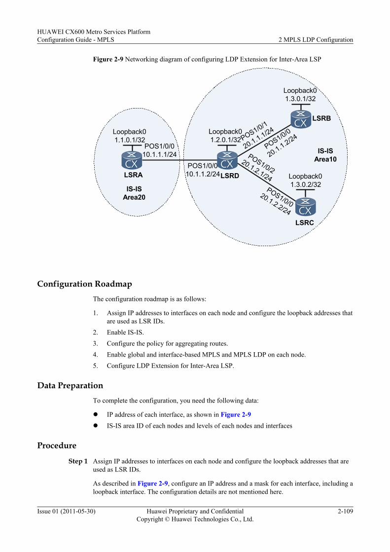
Figure 2-9 Networking diagram of configuring LDP Extension for Inter-Area LSP
POS1/0/010.1.1.1/24 IS-IS
Area10
IS-ISArea20
LSRA
LSRB
LSRC
LSRD
POS1/0/1
20.1.1.1/24
POS1/0/010.1.1.2/24
POS1/0/220.1.2.1/24
POS1/0/0
20.1.1.2/24
POS1/0/020.1.2.2/24
Loopback01.1.0.1/32
Loopback01.3.0.1/32
Loopback01.3.0.2/32
Loopback01.2.0.1/32
Configuration RoadmapThe configuration roadmap is as follows:
1. Assign IP addresses to interfaces on each node and configure the loopback addresses thatare used as LSR IDs.
2. Enable IS-IS.3. Configure the policy for aggregating routes.4. Enable global and interface-based MPLS and MPLS LDP on each node.5. Configure LDP Extension for Inter-Area LSP.
Data PreparationTo complete the configuration, you need the following data:
l IP address of each interface, as shown in Figure 2-9l IS-IS area ID of each nodes and levels of each nodes and interfaces
Procedure
Step 1 Assign IP addresses to interfaces on each node and configure the loopback addresses that areused as LSR IDs.
As described in Figure 2-9, configure an IP address and a mask for each interface, including aloopback interface. The configuration details are not mentioned here.
HUAWEI CX600 Metro Services PlatformConfiguration Guide - MPLS 2 MPLS LDP Configuration
Issue 01 (2011-05-30) Huawei Proprietary and ConfidentialCopyright © Huawei Technologies Co., Ltd.
2-109

Step 2 Enable IS-IS.
# Configure LSRA.
<LSRA> system-view[LSRA] isis 1[LSRA-isis-1] is-level level-2[LSRA-isis-1] network-entity 20.0010.0100.0001.00[LSRA-isis-1] quit[LSRA] interface pos 1/0/0[LSRA-Pos1/0/0] isis enable 1[LSRA-Pos1/0/0] quit[LSRA] interface loopback 0[LSRA-LoopBack0] isis enable 1[LSRA-LoopBack0] quit
# Configure the LSRD.
<LSRD> system-view[LSRD] isis 1[LSRD-isis-1] network-entity 10.0010.0200.0001.00[LSRD-isis-1] quit[LSRD] interface pos 1/0/0[LSRD-Pos1/0/0] isis enable 1[LSRD-Pos1/0/0] isis circuit-level level-2[LSRD-Pos1/0/0] quit[LSRD] interface pos 1/0/1[LSRD-Pos1/0/1] isis enable 1[LSRD-Pos1/0/1] isis circuit-level level-1[LSRD-Pos1/0/1] quit[LSRD] interface pos 1/0/2[LSRD-Pos1/0/2] isis enable 1[LSRD-Pos1/0/2] isis circuit-level level-1[LSRD-Pos1/0/2] quit[LSRD] interface loopback 0[LSRD-LoopBack0] isis enable 1[LSRD-LoopBack0] quit
# Configure LSRB.
<LSRB> system-view[LSRB] isis 1[LSRB-isis-1] is-level level-1[LSRB-isis-1] network-entity 10.0010.0300.0001.00[LSRB-isis-1] quit[LSRB] interface pos 1/0/0[LSRB-Pos1/0/0] isis enable 1[LSRB-Pos1/0/0] quit[LSRB] interface loopback 0[LSRB-LoopBack0] isis enable 1[LSRB-LoopBack0] quit
# Configure LSRC.
<LSRC> system-view[LSRC] isis 1[LSRC-isis-1] is-level level-1[LSRC-isis-1] network-entity 10.0010.0300.0002.00[LSRC-isis-1] quit[LSRC] interface pos 1/0/0[LSRC-Pos1/0/0] isis enable 1[LSRC-Pos1/0/0] quit[LSRC] interface loopback 0[LSRC-LoopBack0] isis enable 1[LSRC-LoopBack0] quit
# On LSRA, run the display ip routing-table command. You can view route information.
[LSRA] display ip routing-table
2 MPLS LDP ConfigurationHUAWEI CX600 Metro Services Platform
Configuration Guide - MPLS
2-110 Huawei Proprietary and ConfidentialCopyright © Huawei Technologies Co., Ltd.
Issue 01 (2011-05-30)
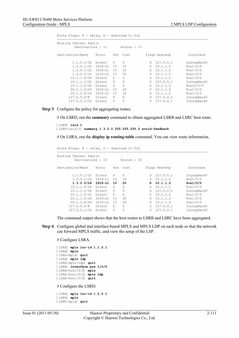
Route Flags: R - relay, D - download to fib------------------------------------------------------------------------------Routing Tables: Public Destinations : 11 Routes : 11
Destination/Mask Proto Pre Cost Flags NextHop Interface
1.1.0.1/32 Direct 0 0 D 127.0.0.1 InLoopBack0 1.2.0.1/32 ISIS-L1 15 10 D 10.1.1.2 Pos1/0/0 1.3.0.1/32 ISIS-L1 15 20 D 10.1.1.2 Pos1/0/0 1.3.0.2/32 ISIS-L1 15 20 D 10.1.1.2 Pos1/0/0 10.1.1.0/24 Direct 0 0 D 10.1.1.1 Pos1/0/0 10.1.1.1/32 Direct 0 0 D 127.0.0.1 InLoopBack0 10.1.1.2/32 Direct 0 0 D 10.1.1.2 Pos10/0/0 20.1.1.0/24 ISIS-L1 15 20 D 10.1.1.2 Pos1/0/0 20.1.2.0/24 ISIS-L1 15 20 D 10.1.1.2 Pos1/0/0 127.0.0.0/8 Direct 0 0 D 127.0.0.1 InLoopBack0 127.0.0.1/32 Direct 0 0 D 127.0.0.1 InLoopBack0
Step 3 Configure the policy for aggregating routes.
# On LSRD, run the summary command to obtain aggregated LSRB and LSRC host route.
[LSRD] isis 1[LSRD-isis-1] summary 1.3.0.0 255.255.255.0 avoid-feedback
# On LSRA, run the display ip routing-table command. You can view route information.
Route Flags: R - relay, D - download to fib------------------------------------------------------------------------------Routing Tables: Public Destinations : 10 Routes : 10
Destination/Mask Proto Pre Cost Flags NextHop Interface
1.1.0.1/32 Direct 0 0 D 127.0.0.1 InLoopBack0 1.2.0.1/32 ISIS-L1 15 10 D 10.1.1.2 Pos1/0/0 1.3.0.0/24 ISIS-L1 15 20 D 10.1.1.2 Pos1/0/0 10.1.1.0/24 Direct 0 0 D 10.1.1.1 Pos1/0/0 10.1.1.1/32 Direct 0 0 D 127.0.0.1 InLoopBack0 10.1.1.2/32 Direct 0 0 D 10.1.1.2 Pos1/0/0 20.1.1.0/24 ISIS-L1 15 20 D 10.1.1.2 Pos1/0/0 20.1.2.0/24 ISIS-L1 15 20 D 10.1.1.2 Pos1/0/0 127.0.0.0/8 Direct 0 0 D 127.0.0.1 InLoopBack0 127.0.0.1/32 Direct 0 0 D 127.0.0.1 InLoopBack0
The command output shows that the host routes to LSRB and LSRC have been aggregated.
Step 4 Configure global and interface-based MPLS and MPLS LDP on each node so that the networkcan forward MPLS traffic, and view the setup of the LSP.
# Configure LSRA.
[LSRA] mpls lsr-id 1.1.0.1[LSRA] mpls[LSRA-mpls] quit[LSRA] mpls ldp[LSRA-mpls-ldp] quit[LSRA] interface pos 1/0/0[LSRA-Pos1/0/0] mpls[LSRA-Pos1/0/0] mpls ldp[LSRA-Pos1/0/0] quit
# Configure the LSRD.
[LSRD] mpls lsr-id 1.2.0.1[LSRD] mpls[LSRD-mpls] quit
HUAWEI CX600 Metro Services PlatformConfiguration Guide - MPLS 2 MPLS LDP Configuration
Issue 01 (2011-05-30) Huawei Proprietary and ConfidentialCopyright © Huawei Technologies Co., Ltd.
2-111
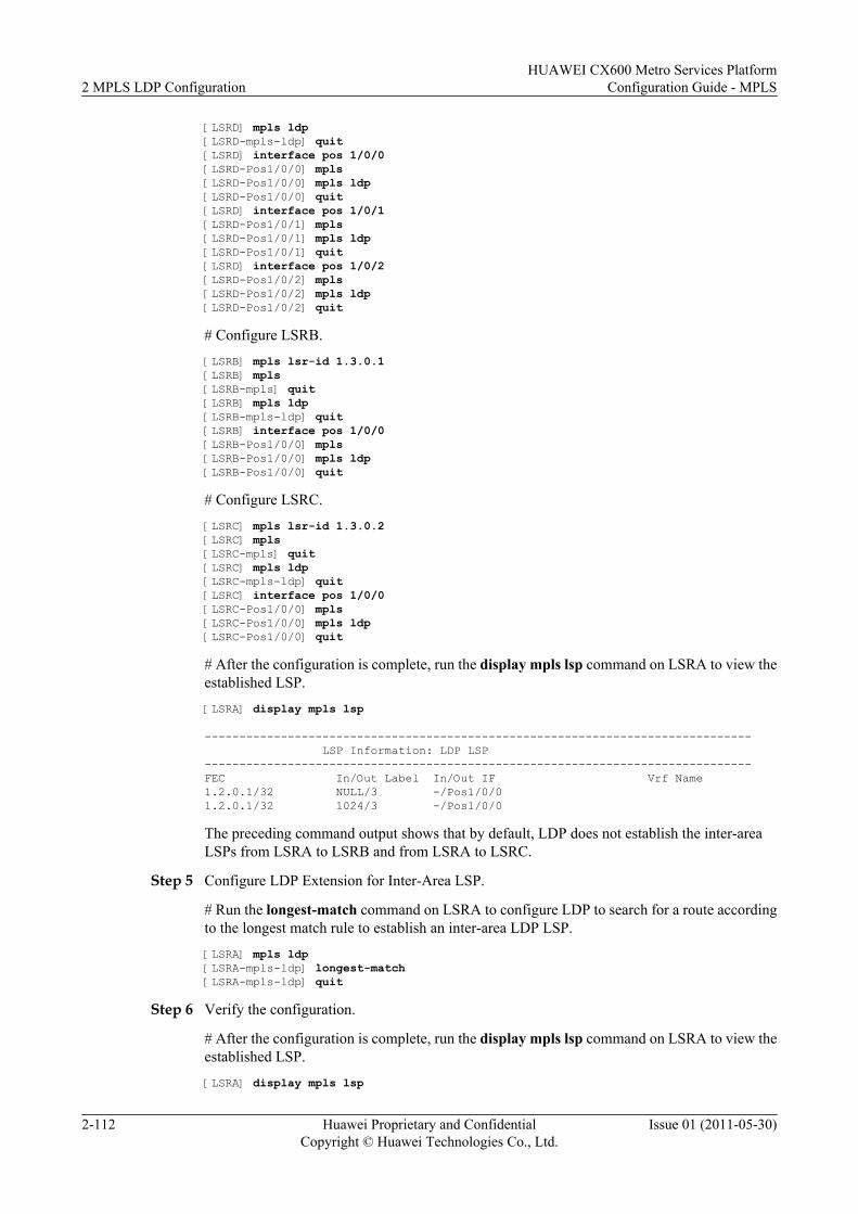
[LSRD] mpls ldp[LSRD-mpls-ldp] quit[LSRD] interface pos 1/0/0[LSRD-Pos1/0/0] mpls[LSRD-Pos1/0/0] mpls ldp[LSRD-Pos1/0/0] quit[LSRD] interface pos 1/0/1[LSRD-Pos1/0/1] mpls[LSRD-Pos1/0/1] mpls ldp[LSRD-Pos1/0/1] quit[LSRD] interface pos 1/0/2[LSRD-Pos1/0/2] mpls[LSRD-Pos1/0/2] mpls ldp[LSRD-Pos1/0/2] quit
# Configure LSRB.[LSRB] mpls lsr-id 1.3.0.1[LSRB] mpls[LSRB-mpls] quit[LSRB] mpls ldp[LSRB-mpls-ldp] quit[LSRB] interface pos 1/0/0[LSRB-Pos1/0/0] mpls[LSRB-Pos1/0/0] mpls ldp[LSRB-Pos1/0/0] quit
# Configure LSRC.[LSRC] mpls lsr-id 1.3.0.2[LSRC] mpls[LSRC-mpls] quit[LSRC] mpls ldp[LSRC-mpls-ldp] quit[LSRC] interface pos 1/0/0[LSRC-Pos1/0/0] mpls[LSRC-Pos1/0/0] mpls ldp[LSRC-Pos1/0/0] quit
# After the configuration is complete, run the display mpls lsp command on LSRA to view theestablished LSP.[LSRA] display mpls lsp
------------------------------------------------------------------------------- LSP Information: LDP LSP-------------------------------------------------------------------------------FEC In/Out Label In/Out IF Vrf Name1.2.0.1/32 NULL/3 -/Pos1/0/01.2.0.1/32 1024/3 -/Pos1/0/0
The preceding command output shows that by default, LDP does not establish the inter-areaLSPs from LSRA to LSRB and from LSRA to LSRC.
Step 5 Configure LDP Extension for Inter-Area LSP.
# Run the longest-match command on LSRA to configure LDP to search for a route accordingto the longest match rule to establish an inter-area LDP LSP.[LSRA] mpls ldp[LSRA-mpls-ldp] longest-match[LSRA-mpls-ldp] quit
Step 6 Verify the configuration.
# After the configuration is complete, run the display mpls lsp command on LSRA to view theestablished LSP.[LSRA] display mpls lsp
2 MPLS LDP ConfigurationHUAWEI CX600 Metro Services Platform
Configuration Guide - MPLS
2-112 Huawei Proprietary and ConfidentialCopyright © Huawei Technologies Co., Ltd.
Issue 01 (2011-05-30)
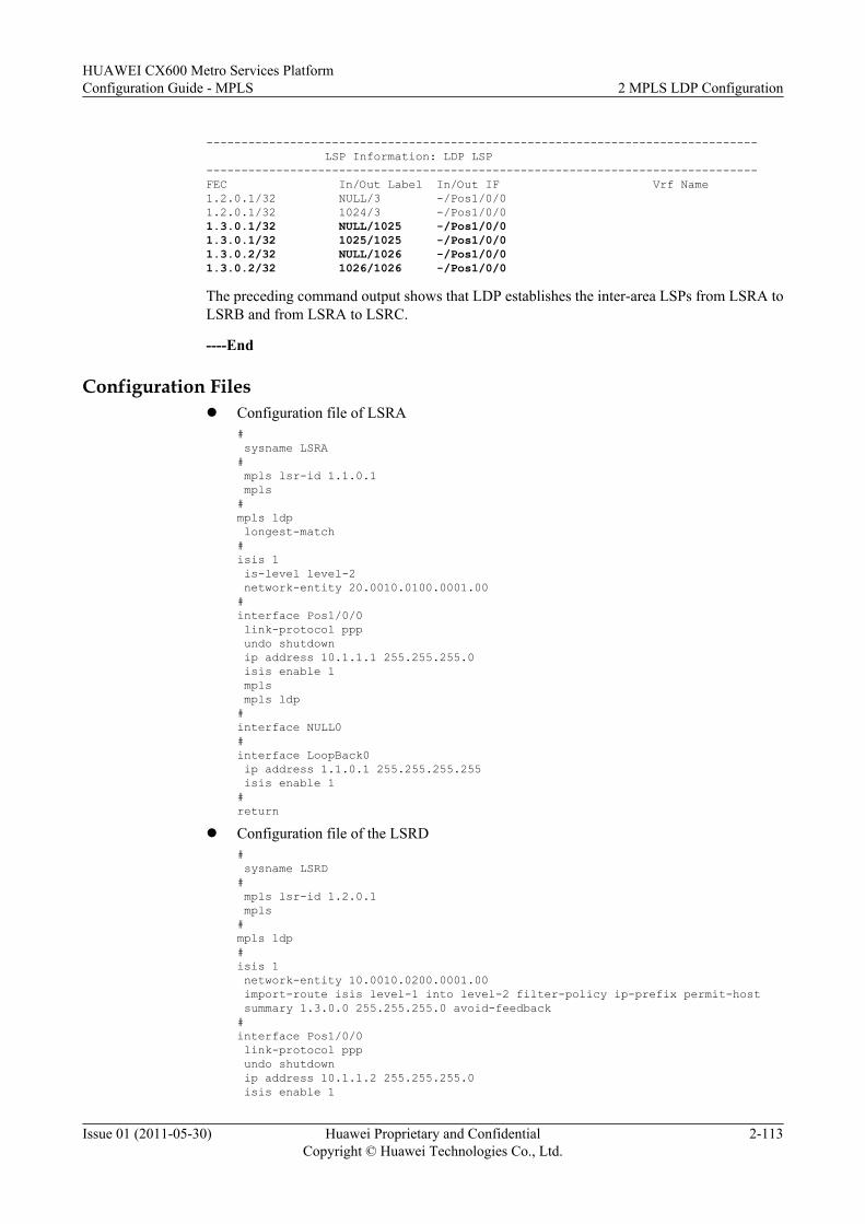
------------------------------------------------------------------------------- LSP Information: LDP LSP-------------------------------------------------------------------------------FEC In/Out Label In/Out IF Vrf Name1.2.0.1/32 NULL/3 -/Pos1/0/01.2.0.1/32 1024/3 -/Pos1/0/01.3.0.1/32 NULL/1025 -/Pos1/0/01.3.0.1/32 1025/1025 -/Pos1/0/01.3.0.2/32 NULL/1026 -/Pos1/0/01.3.0.2/32 1026/1026 -/Pos1/0/0
The preceding command output shows that LDP establishes the inter-area LSPs from LSRA toLSRB and from LSRA to LSRC.
----End
Configuration Filesl Configuration file of LSRA
# sysname LSRA# mpls lsr-id 1.1.0.1 mpls#mpls ldp longest-match#isis 1 is-level level-2 network-entity 20.0010.0100.0001.00#interface Pos1/0/0 link-protocol ppp undo shutdown ip address 10.1.1.1 255.255.255.0 isis enable 1 mpls mpls ldp#interface NULL0#interface LoopBack0 ip address 1.1.0.1 255.255.255.255 isis enable 1#return
l Configuration file of the LSRD# sysname LSRD# mpls lsr-id 1.2.0.1 mpls#mpls ldp#isis 1 network-entity 10.0010.0200.0001.00 import-route isis level-1 into level-2 filter-policy ip-prefix permit-host summary 1.3.0.0 255.255.255.0 avoid-feedback#interface Pos1/0/0 link-protocol ppp undo shutdown ip address 10.1.1.2 255.255.255.0 isis enable 1
HUAWEI CX600 Metro Services PlatformConfiguration Guide - MPLS 2 MPLS LDP Configuration
Issue 01 (2011-05-30) Huawei Proprietary and ConfidentialCopyright © Huawei Technologies Co., Ltd.
2-113
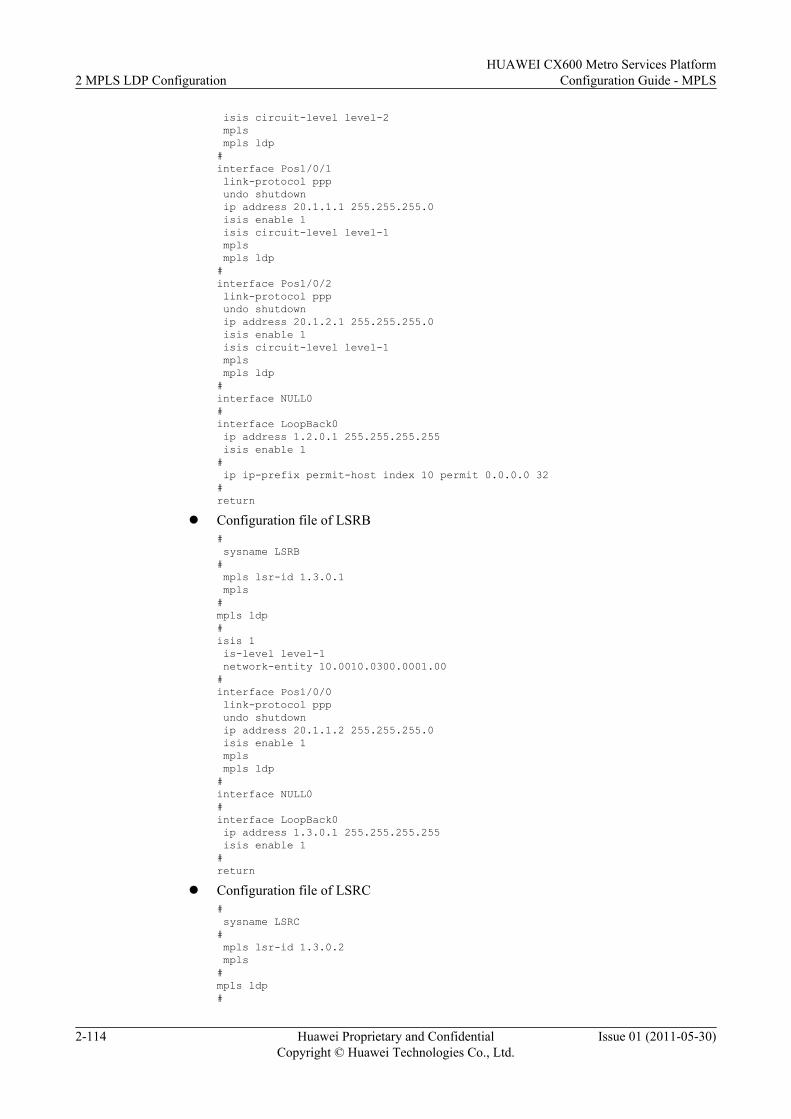
isis circuit-level level-2 mpls mpls ldp#interface Pos1/0/1 link-protocol ppp undo shutdown ip address 20.1.1.1 255.255.255.0 isis enable 1 isis circuit-level level-1 mpls mpls ldp#interface Pos1/0/2 link-protocol ppp undo shutdown ip address 20.1.2.1 255.255.255.0 isis enable 1 isis circuit-level level-1 mpls mpls ldp#interface NULL0#interface LoopBack0 ip address 1.2.0.1 255.255.255.255 isis enable 1# ip ip-prefix permit-host index 10 permit 0.0.0.0 32#return
l Configuration file of LSRB# sysname LSRB# mpls lsr-id 1.3.0.1 mpls#mpls ldp#isis 1 is-level level-1 network-entity 10.0010.0300.0001.00#interface Pos1/0/0 link-protocol ppp undo shutdown ip address 20.1.1.2 255.255.255.0 isis enable 1 mpls mpls ldp#interface NULL0#interface LoopBack0 ip address 1.3.0.1 255.255.255.255 isis enable 1#return
l Configuration file of LSRC# sysname LSRC# mpls lsr-id 1.3.0.2 mpls#mpls ldp#
2 MPLS LDP ConfigurationHUAWEI CX600 Metro Services Platform
Configuration Guide - MPLS
2-114 Huawei Proprietary and ConfidentialCopyright © Huawei Technologies Co., Ltd.
Issue 01 (2011-05-30)
isis 1 is-level level-1 network-entity 10.0010.0300.0002.00#interface Pos1/0/0 link-protocol ppp undo shutdown ip address 20.1.2.2 255.255.255.0 isis enable 1 mpls mpls ldp#interface LoopBack0 ip address 1.3.0.2 255.255.255.255 isis enable 1#return
2.15.9 Example for Configuring Static BFD for LDP LSPThis section provides an example for configuring a static BFD session to detect an LDP LSP,which consists of enabling MPLS and MPLS LDP on each device and interface and enablingBFD on both ends of a link to be detected.
Networking RequirementsAs shown in Figure 2-10, an LDP LSP is set up along the path of PE1 → P1→ PE2 and the pathof PE2 → P2 → PE1 works as an IP link. Static BFD sessions are required to detect theconnectivity of the LDP LSP.
Figure 2-10 Networking diagram of configuring static BFD for LDP LSP
Loopback11.1.1.1/32
Loopback13.3.3.3/32
Loopback12.2.2.2/32
PE1
Loopback14.4.4.4/32
P1
P2
PE2POS1/0/110.1.2.1/24
POS1/0/0
10.1.1.2/24POS1/0/1
10.1.5.2/24
POS1/0/010.1.2.2/24 POS1/0/1
10.1.4.2/24
POS1/0/010.1.5.1/24
POS1/0/1
10.1.4.1/24
POS1/0/0
10.1.1.1/24
LDP LSP
HUAWEI CX600 Metro Services PlatformConfiguration Guide - MPLS 2 MPLS LDP Configuration
Issue 01 (2011-05-30) Huawei Proprietary and ConfidentialCopyright © Huawei Technologies Co., Ltd.
2-115
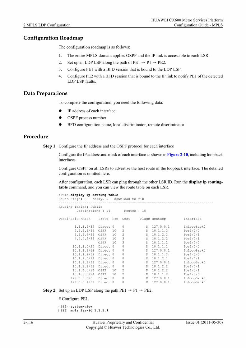
Configuration RoadmapThe configuration roadmap is as follows:
1. The entire MPLS domain applies OSPF and the IP link is accessible to each LSR.2. Set up an LDP LSP along the path of PE1 → P1 → PE2.3. Configure PE1 with a BFD session that is bound to the LDP LSP.4. Configure PE2 with a BFD session that is bound to the IP link to notify PE1 of the detected
LDP LSP faults.
Data PreparationsTo complete the configuration, you need the following data:
l IP address of each interfacel OSPF process numberl BFD configuration name, local discriminator, remote discriminator
Procedure
Step 1 Configure the IP address and the OSPF protocol for each interface
Configure the IP address and mask of each interface as shown in Figure 2-10, including loopbackinterfaces.
Configure OSPF on all LSRs to advertise the host route of the loopback interface. The detailedconfiguration is omitted here.
After configuration, each LSR can ping through the other LSR ID. Run the display ip routing-table command, and you can view the route table on each LSR.
<PE1> display ip routing-tableRoute Flags: R - relay, D - download to fib------------------------------------------------------------------------------Routing Tables: Public Destinations : 14 Routes : 15
Destination/Mask Proto Pre Cost Flags NextHop Interface
1.1.1.9/32 Direct 0 0 D 127.0.0.1 InLoopBack0 2.2.2.9/32 OSPF 10 2 D 10.1.1.2 Pos1/0/0 3.3.3.9/32 OSPF 10 2 D 10.1.2.2 Pos1/0/1 4.4.4.9/32 OSPF 10 3 D 10.1.2.2 Pos1/0/1 OSPF 10 3 D 10.1.1.2 Pos1/0/0 10.1.1.0/24 Direct 0 0 D 10.1.1.1 Pos1/0/0 10.1.1.1/32 Direct 0 0 D 127.0.0.1 InLoopBack0 10.1.1.2/32 Direct 0 0 D 10.1.1.2 Pos1/0/0 10.1.2.0/24 Direct 0 0 D 10.1.2.1 Pos1/0/1 10.1.2.1/32 Direct 0 0 D 127.0.0.1 InLoopBack0 10.1.2.2/32 Direct 0 0 D 10.1.2.2 Pos1/0/1 10.1.4.0/24 OSPF 10 2 D 10.1.2.2 Pos1/0/1 10.1.5.0/24 OSPF 10 2 D 10.1.1.2 Pos1/0/0 127.0.0.0/8 Direct 0 0 D 127.0.0.1 InLoopBack0 127.0.0.1/32 Direct 0 0 D 127.0.0.1 InLoopBack0
Step 2 Set up an LDP LSP along the path PE1 → P1 → PE2.
# Configure PE1.
<PE1> system-view[PE1] mpls lsr-id 1.1.1.9
2 MPLS LDP ConfigurationHUAWEI CX600 Metro Services Platform
Configuration Guide - MPLS
2-116 Huawei Proprietary and ConfidentialCopyright © Huawei Technologies Co., Ltd.
Issue 01 (2011-05-30)
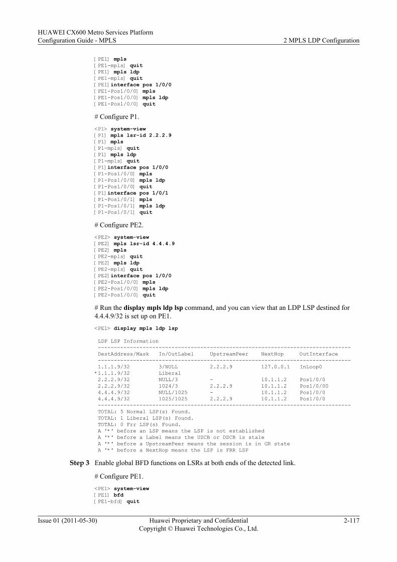
[PE1] mpls[PE1-mpls] quit[PE1] mpls ldp[PE1-mpls] quit[PE1]interface pos 1/0/0[PE1-Pos1/0/0] mpls[PE1-Pos1/0/0] mpls ldp[PE1-Pos1/0/0] quit
# Configure P1.
<P1> system-view[P1] mpls lsr-id 2.2.2.9[P1] mpls[P1-mpls] quit[P1] mpls ldp[P1-mpls] quit[P1]interface pos 1/0/0[P1-Pos1/0/0] mpls[P1-Pos1/0/0] mpls ldp[P1-Pos1/0/0] quit[P1]interface pos 1/0/1[P1-Pos1/0/1] mpls[P1-Pos1/0/1] mpls ldp[P1-Pos1/0/1] quit
# Configure PE2.
<PE2> system-view[PE2] mpls lsr-id 4.4.4.9[PE2] mpls[PE2-mpls] quit[PE2] mpls ldp[PE2-mpls] quit[PE2]interface pos 1/0/0[PE2-Pos1/0/0] mpls[PE2-Pos1/0/0] mpls ldp[PE2-Pos1/0/0] quit
# Run the display mpls ldp lsp command, and you can view that an LDP LSP destined for4.4.4.9/32 is set up on PE1.
<PE1> display mpls ldp lsp
LDP LSP Information ------------------------------------------------------------------------------- DestAddress/Mask In/OutLabel UpstreamPeer NextHop OutInterface ------------------------------------------------------------------------------- 1.1.1.9/32 3/NULL 2.2.2.9 127.0.0.1 InLoop0*1.1.1.9/32 Liberal 2.2.2.9/32 NULL/3 - 10.1.1.2 Pos1/0/0 2.2.2.9/32 1024/3 2.2.2.9 10.1.1.2 Pos1/0/00 4.4.4.9/32 NULL/1025 - 10.1.1.2 Pos1/0/0 4.4.4.9/32 1025/1025 2.2.2.9 10.1.1.2 Pos1/0/0 ------------------------------------------------------------------------------- TOTAL: 5 Normal LSP(s) Found. TOTAL: 1 Liberal LSP(s) Found. TOTAL: 0 Frr LSP(s) Found. A '*' before an LSP means the LSP is not established A '*' before a Label means the USCB or DSCB is stale A '*' before a UpstreamPeer means the session is in GR state A '*' before a NextHop means the LSP is FRR LSP
Step 3 Enable global BFD functions on LSRs at both ends of the detected link.
# Configure PE1.
<PE1> system-view[PE1] bfd[PE1-bfd] quit
HUAWEI CX600 Metro Services PlatformConfiguration Guide - MPLS 2 MPLS LDP Configuration
Issue 01 (2011-05-30) Huawei Proprietary and ConfidentialCopyright © Huawei Technologies Co., Ltd.
2-117
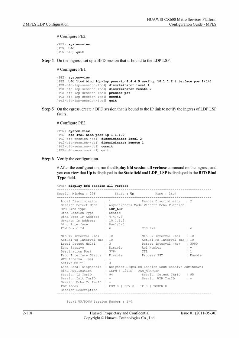
# Configure PE2.
<PE2> system-view[PE2] bfd[PE2-bfd] quit
Step 4 On the ingress, set up a BFD session that is bound to the LDP LSP.
# Configure PE1.
<PE1> system-view[PE1] bfd 1to4 bind ldp-lsp peer-ip 4.4.4.9 nexthop 10.1.1.2 interface pos 1/0/0[PE1-bfd-lsp-session-1to4] discriminator local 1[PE1-bfd-lsp-session-1to4] discriminator remote 2[PE1-bfd-lsp-session-1to4] process-pst[PE1-bfd-lsp-session-1to4] commit[PE1-bfd-lsp-session-1to4] quit
Step 5 On the egress, create a BFD session that is bound to the IP link to notify the ingress of LDP LSPfaults.
# Configure PE2.
<PE2> system-view[PE2] bfd 4to1 bind peer-ip 1.1.1.9[PE2-bfd-session-4ot1] discriminator local 2[PE2-bfd-session-4ot1] discriminator remote 1[PE2-bfd-session-4ot1] commit[PE2-bfd-session-4ot1] quit
Step 6 Verify the configuration.
# After the configuration, run the display bfd session all verbose command on the ingress, andyou can view that Up is displayed in the State field and LDP_LSP is displayed in the BFD BindType field.
<PE1> display bfd session all verbose--------------------------------------------------------------------------------Session MIndex : 256 State : Up Name : 1to4-------------------------------------------------------------------------------- Local Discriminator : 1 Remote Discriminator : 2 Session Detect Mode : Asynchronous Mode Without Echo Function BFD Bind Type : LDP_LSP Bind Session Type : Static Bind Peer IP Address : 4.4.4.9 NextHop Ip Address : 10.1.1.2 Bind Interface : Pos1/0/0 FSM Board Id : 6 TOS-EXP : 6 Min Tx Interval (ms) : 10 Min Rx Interval (ms) : 10 Actual Tx Interval (ms): 10 Actual Rx Interval (ms): 10 Local Detect Multi : 3 Detect Interval (ms) : 3000 Echo Passive : Disable Acl Number : - Destination Port : 3784 TTL : 1 Proc Interface Status : Disable Process PST : Enable WTR Interval (ms) : - Active Multi : 3 Last Local Diagnostic : Neighbor Signaled Session Down(Receive AdminDown) Bind Application : LSPM | L2VPN | OAM_MANAGER Session TX TmrID : 94 Session Detect TmrID : 95 Session Init TmrID : - Session WTR TmrID : - Session Echo Tx TmrID : - PDT Index : FSM-0 | RCV-0 | IF-0 | TOKEN-0 Session Description : ---------------------------------------------------------------------------------
Total UP/DOWN Session Number : 1/0
2 MPLS LDP ConfigurationHUAWEI CX600 Metro Services Platform
Configuration Guide - MPLS
2-118 Huawei Proprietary and ConfidentialCopyright © Huawei Technologies Co., Ltd.
Issue 01 (2011-05-30)
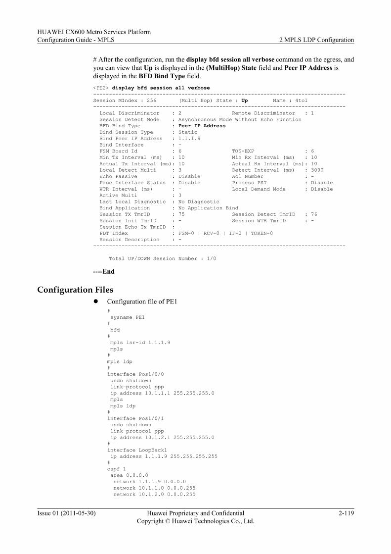
# After the configuration, run the display bfd session all verbose command on the egress, andyou can view that Up is displayed in the (MultiHop) State field and Peer IP Address isdisplayed in the BFD Bind Type field.<PE2> display bfd session all verbose--------------------------------------------------------------------------------Session MIndex : 256 (Multi Hop) State : Up Name : 4to1-------------------------------------------------------------------------------- Local Discriminator : 2 Remote Discriminator : 1 Session Detect Mode : Asynchronous Mode Without Echo Function BFD Bind Type : Peer IP Address Bind Session Type : Static Bind Peer IP Address : 1.1.1.9 Bind Interface : - FSM Board Id : 6 TOS-EXP : 6 Min Tx Interval (ms) : 10 Min Rx Interval (ms) : 10 Actual Tx Interval (ms): 10 Actual Rx Interval (ms): 10 Local Detect Multi : 3 Detect Interval (ms) : 3000 Echo Passive : Disable Acl Number : - Proc Interface Status : Disable Process PST : Disable WTR Interval (ms) : - Local Demand Mode : Disable Active Multi : 3 Last Local Diagnostic : No Diagnostic Bind Application : No Application Bind Session TX TmrID : 75 Session Detect TmrID : 76 Session Init TmrID : - Session WTR TmrID : - Session Echo Tx TmrID : - PDT Index : FSM-0 | RCV-0 | IF-0 | TOKEN-0 Session Description : ---------------------------------------------------------------------------------
Total UP/DOWN Session Number : 1/0
----End
Configuration Filesl Configuration file of PE1
# sysname PE1# bfd# mpls lsr-id 1.1.1.9 mpls#mpls ldp#interface Pos1/0/0 undo shutdown link-protocol ppp ip address 10.1.1.1 255.255.255.0 mpls mpls ldp#interface Pos1/0/1 undo shutdown link-protocol ppp ip address 10.1.2.1 255.255.255.0#interface LoopBack1 ip address 1.1.1.9 255.255.255.255#ospf 1 area 0.0.0.0 network 1.1.1.9 0.0.0.0 network 10.1.1.0 0.0.0.255 network 10.1.2.0 0.0.0.255
HUAWEI CX600 Metro Services PlatformConfiguration Guide - MPLS 2 MPLS LDP Configuration
Issue 01 (2011-05-30) Huawei Proprietary and ConfidentialCopyright © Huawei Technologies Co., Ltd.
2-119
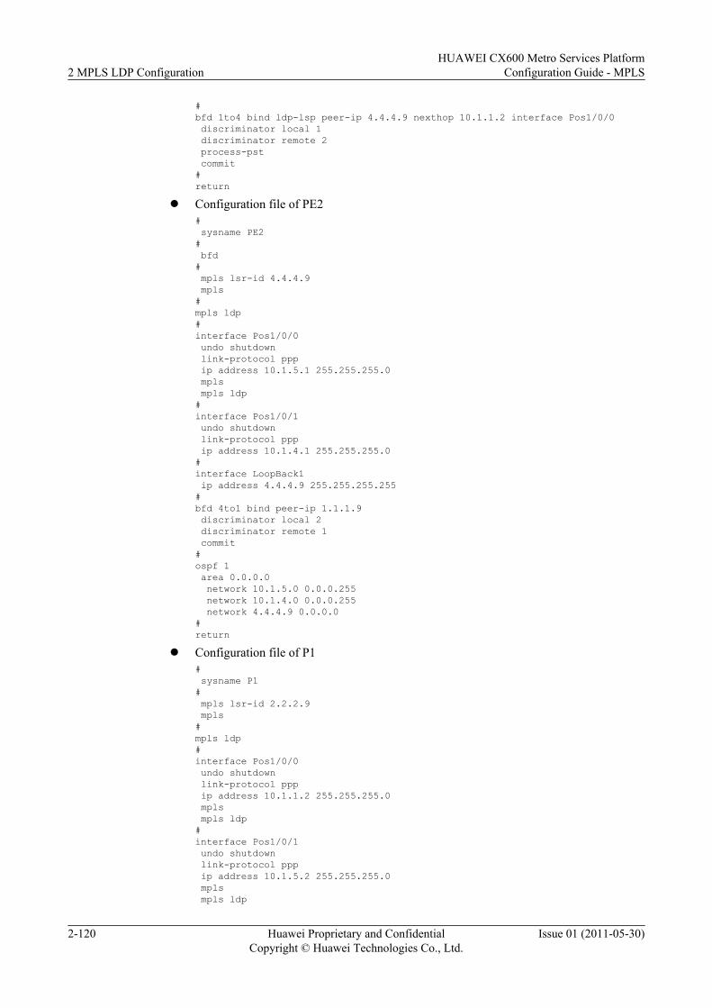
#bfd 1to4 bind ldp-lsp peer-ip 4.4.4.9 nexthop 10.1.1.2 interface Pos1/0/0 discriminator local 1 discriminator remote 2 process-pst commit#return
l Configuration file of PE2# sysname PE2# bfd# mpls lsr-id 4.4.4.9 mpls#mpls ldp#interface Pos1/0/0 undo shutdown link-protocol ppp ip address 10.1.5.1 255.255.255.0 mpls mpls ldp#interface Pos1/0/1 undo shutdown link-protocol ppp ip address 10.1.4.1 255.255.255.0#interface LoopBack1 ip address 4.4.4.9 255.255.255.255#bfd 4to1 bind peer-ip 1.1.1.9 discriminator local 2 discriminator remote 1 commit#ospf 1 area 0.0.0.0 network 10.1.5.0 0.0.0.255 network 10.1.4.0 0.0.0.255 network 4.4.4.9 0.0.0.0#return
l Configuration file of P1# sysname P1# mpls lsr-id 2.2.2.9 mpls#mpls ldp#interface Pos1/0/0 undo shutdown link-protocol ppp ip address 10.1.1.2 255.255.255.0 mpls mpls ldp#interface Pos1/0/1 undo shutdown link-protocol ppp ip address 10.1.5.2 255.255.255.0 mpls mpls ldp
2 MPLS LDP ConfigurationHUAWEI CX600 Metro Services Platform
Configuration Guide - MPLS
2-120 Huawei Proprietary and ConfidentialCopyright © Huawei Technologies Co., Ltd.
Issue 01 (2011-05-30)
#interface LoopBack1 ip address 2.2.2.9 255.255.255.255#ospf 1 area 0.0.0.0 network 2.2.2.9 0.0.0.0 network 10.1.1.0 0.0.0.255 network 10.1.5.0 0.0.0.255#return
l Configuration file of P2# sysname P2#interface Pos1/0/0 undo shutdown link-protocol ppp ip address 10.1.2.2 255.255.255.0#interface Pos1/0/1 undo shutdown link-protocol ppp ip address 10.1.4.2 255.255.255.0#interface LoopBack1 ip address 3.3.3.9 255.255.255.255#ospf 1 area 0.0.0.0 network 3.3.3.9 0.0.0.0 network 10.1.4.0 0.0.0.255 network 10.1.2.0 0.0.0.255#return
2.15.10 Example for Configuring Dynamic BFD for LDP LSPThis section provides an example for configuring a dynamic BFD session to detect an LDP LSP,which consists of enabling MPLS and MPLS LDP on each device and interface and enablingBFD on the ingress node and egress node to be detected.
Networking Requirements
As shown in Figure 2-11, LSRA, LSRB, and LSRC locates at one MPLS domain. An LDP LSPis established between LSRA and LSRC that requires dynamic BFD for LDP LSP. The time todetect a failure is within 50 ms.
Figure 2-11 Networking diagram of configuring dynamic BFD for LDP LSP
LSRB
POS1/0/0192.168.1.1/24
POS1/0/0192.168.1.2/24LSRA LSRC
POS2/0/0192.168.2.1/24
POS1/0/0192.168.2.2/24
Loopback11.1.1.9/32
Loopback12.2.2.9/32
Loopback13.3.3.9/32
HUAWEI CX600 Metro Services PlatformConfiguration Guide - MPLS 2 MPLS LDP Configuration
Issue 01 (2011-05-30) Huawei Proprietary and ConfidentialCopyright © Huawei Technologies Co., Ltd.
2-121
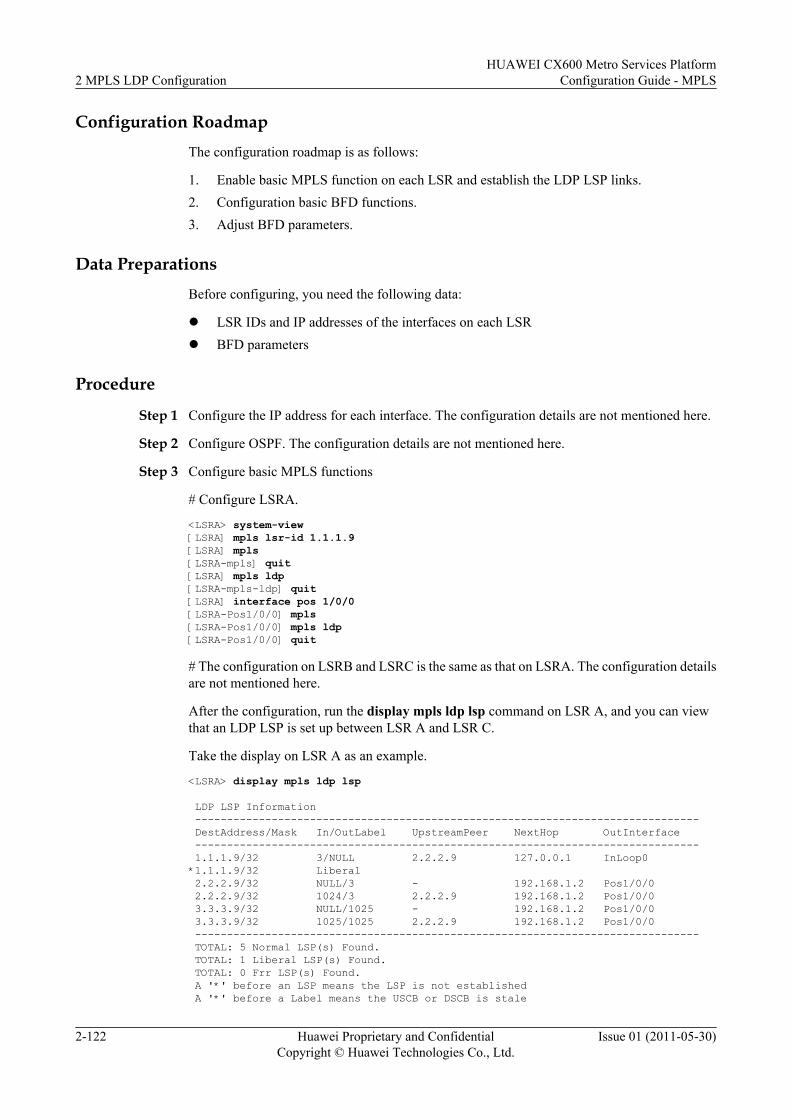
Configuration RoadmapThe configuration roadmap is as follows:
1. Enable basic MPLS function on each LSR and establish the LDP LSP links.2. Configuration basic BFD functions.3. Adjust BFD parameters.
Data PreparationsBefore configuring, you need the following data:
l LSR IDs and IP addresses of the interfaces on each LSRl BFD parameters
Procedure
Step 1 Configure the IP address for each interface. The configuration details are not mentioned here.
Step 2 Configure OSPF. The configuration details are not mentioned here.
Step 3 Configure basic MPLS functions
# Configure LSRA.
<LSRA> system-view[LSRA] mpls lsr-id 1.1.1.9[LSRA] mpls[LSRA-mpls] quit[LSRA] mpls ldp[LSRA-mpls-ldp] quit[LSRA] interface pos 1/0/0[LSRA-Pos1/0/0] mpls[LSRA-Pos1/0/0] mpls ldp[LSRA-Pos1/0/0] quit
# The configuration on LSRB and LSRC is the same as that on LSRA. The configuration detailsare not mentioned here.
After the configuration, run the display mpls ldp lsp command on LSR A, and you can viewthat an LDP LSP is set up between LSR A and LSR C.
Take the display on LSR A as an example.
<LSRA> display mpls ldp lsp
LDP LSP Information ------------------------------------------------------------------------------- DestAddress/Mask In/OutLabel UpstreamPeer NextHop OutInterface ------------------------------------------------------------------------------- 1.1.1.9/32 3/NULL 2.2.2.9 127.0.0.1 InLoop0*1.1.1.9/32 Liberal 2.2.2.9/32 NULL/3 - 192.168.1.2 Pos1/0/0 2.2.2.9/32 1024/3 2.2.2.9 192.168.1.2 Pos1/0/0 3.3.3.9/32 NULL/1025 - 192.168.1.2 Pos1/0/0 3.3.3.9/32 1025/1025 2.2.2.9 192.168.1.2 Pos1/0/0 ------------------------------------------------------------------------------- TOTAL: 5 Normal LSP(s) Found. TOTAL: 1 Liberal LSP(s) Found. TOTAL: 0 Frr LSP(s) Found. A '*' before an LSP means the LSP is not established A '*' before a Label means the USCB or DSCB is stale
2 MPLS LDP ConfigurationHUAWEI CX600 Metro Services Platform
Configuration Guide - MPLS
2-122 Huawei Proprietary and ConfidentialCopyright © Huawei Technologies Co., Ltd.
Issue 01 (2011-05-30)
A '*' before a UpstreamPeer means the session is in GR state A '*' before a NextHop means the LSP is FRR LSP
Step 4 Configure dynamic BFD for LDP LSP from LSRA to LSRC.
# Configure an FEC list on LSRA to ensure that the BFD for LDP LSP only from LSRA toLSRC is triggered.
[LSRA] fec-list tortc[LSRA-fec-list-tortc] fec-node 3.3.3.9
# Enable BFD on LSRA. Specify the FEC list that triggers a BFD session dynamically. AdjustBFD parameters.
[LSRA] bfd[LSRA-bfd] quit[LSRA] mpls[LSRA-mpls] mpls bfd-trigger fec-list tortc[LSRA-mpls] mpls bfd enable[LSRA-mpls] mpls bfd min-tx-interval 600 min-rx-interval 600 detect-multiplier 4
# Configure on LSRC with passive enabling BFD for LSP capability.
[LSRC] bfd[LSRC-bfd] mpls-passive
Step 5 Verify the configuration.
# Run the display bfd session all verbose command, and you can view the BFD session statusthat is created dynamically.
<LSRA> display bfd session all verbose-----------------------------------------------------------Session MIndex : 256 State : Up Name : dyn_8192----------------------------------------------------------- Local Discriminator: 8192 Remote Discriminator : 8193 Session Detect Mode : Asynchronous Mode Without Echo Function BFD Bind Type : LDP_LSP Bind Session Type : Dynamic Bind Peer Ip Address : 3.3.3.9 NextHop Ip Address : 192.168.1.2 Bind Interface : Pos1/0/0 FSM Board Id : 1 TOS-EXP : 6 Min Tx Interval (ms) : 100 Min Rx Interval (ms) : 600 Actual Tx Interval (ms): 100 Actual Rx Interval (ms): 600 Local Detect Multi : 4 Detect Interval (ms) : 1800 Echo Passive : Disable Acl Number : -- Destination Port : 3784 TTL : 1 Proc interface status : Disable Process PST : Enable WTR Interval (ms) : -- Active Multi : 3 Last Local Diagnostic : No Diagnostic Bind Application : LSPM | L2VPN | OAM_MANAGER Session TX TmrID : 77 Session Detect TmrID : 78 Session Init TmrID : -- Session WTR TmrID : -- Session Echo Tx TmrID : -- PDT Index : FSM-0 | RCV-0 | IF-0 | TOKEN-0 Session Description : ------------------------------------------------------------- Total UP/DOWN Session Number : 1/0
# Display the status of BFD session created dynamically on LSRC. The field of BFD bind typeis Peer IP Address. This indicates the BFD packets sent by LSRC are transported through IProute.
<LSRC> display bfd session passive-dynamic verbose-----------------------------------------------------------Session MIndex : 257 (Multi Hop) State : Up Name : dyn_8193
HUAWEI CX600 Metro Services PlatformConfiguration Guide - MPLS 2 MPLS LDP Configuration
Issue 01 (2011-05-30) Huawei Proprietary and ConfidentialCopyright © Huawei Technologies Co., Ltd.
2-123
----------------------------------------------------------- Local Discriminator : 8193 Remote Discriminator : 8192 Session Detect Mode : Asynchronous Mode Without Echo Function BFD Bind Type : Peer Ip Address Bind Session Type : Entire_Dynamic Bind Peer Ip Address : 1.1.1.9 Bind Interface : -- FSM Board Id : 1 TOS-EXP : 6 Min Tx Interval (ms) : 100 Min Rx Interval (ms) : 100 Actual Tx Interval (ms): 600 Actual Rx Interval (ms): 100 Local Detect Multi : 3 Detect Interval (ms) : 400 Echo Passive : Disabl Acl Number : -- Proc interface status : Disable Process PST : Disable WTR Interval (ms) : -- Local Demand Mode : Disable Active Multi : 4 Last Local Diagnostic : No Diagnostic Bind Application Session TX TmrID : 75 Session Detect TmrID : 76 Session Init TmrID : -- Session WTR TmrID : -- Session Echo Tx TmrID : -- PDT Index : FSM-0 | RCV-0 | IF-0 | TOKEN-0 Session Description : -------------------------------------------------------------
Total UP/DOWN Session Number : 1/0
----End
Configuration Filesl Configuration file of LSRA
# sysname LSRA# bfd# mpls lsr-id 1.1.1.9 mpls mpls bfd enable mpls bfd-trigger fec-list tortc mpls bfd min-tx-interval 600 min-rx-interval 600 detect-multiplier 4# fec-list tortc fec-node 3.3.3.9#mpls ldp#interface Pos1/0/0 link-protocol ppp undo shutdown ip address 192.168.1.1 255.255.255.0 mpls mpls ldp#interface LoopBack1 ip address 1.1.1.9 255.255.255.255#ospf 100 area 0.0.0.0 network 1.1.1.9 0.0.0.0 network 192.168.1.0 0.0.0.255#return
l Configuration file of LSRB# sysname LSRB#
2 MPLS LDP ConfigurationHUAWEI CX600 Metro Services Platform
Configuration Guide - MPLS
2-124 Huawei Proprietary and ConfidentialCopyright © Huawei Technologies Co., Ltd.
Issue 01 (2011-05-30)
mpls lsr-id 2.2.2.9 mpls#mpls ldp#interface Pos1/0/0 link-protocol ppp undo shutdown ip address 192.168.1.2 255.255.255.0 mpls mpls ldp#interface Pos2/0/0 link-protocol ppp undo shutdown ip address 192.168.2.1 255.255.255.0 mpls mpls ldp#interface LoopBack1 ip address 2.2.2.9 255.255.255.255#ospf 100 area 0.0.0.0 network 2.2.2.9 0.0.0.0 network 192.168.1.0 0.0.0.255 network 192.168.2.0 0.0.0.255#return
l Configuration file of LSRC# sysname LSRC# bfd mpls-passive# mpls lsr-id 3.3.3.9 mpls#mpls ldp#interface Pos1/0/0 link-protocol ppp undo shutdown ip address 192.168.2.2 255.255.255.0 mpls mpls ldp#interface LoopBack1 ip address 3.3.3.9 255.255.255.255#ospf 100 area 0.0.0.0 network 3.3.3.9 0.0.0.0 network 192.168.2.0 0.0.0.255#return
2.15.11 Example for Configuring Manual LDP FRRThis section provides an example for configuring Manual LDP FRR, which consists of enablingMPLS and MPLS LDP on each device and interface and specifying the outgoing interface andthe next hop of the specified backup LSP.
HUAWEI CX600 Metro Services PlatformConfiguration Guide - MPLS 2 MPLS LDP Configuration
Issue 01 (2011-05-30) Huawei Proprietary and ConfidentialCopyright © Huawei Technologies Co., Ltd.
2-125
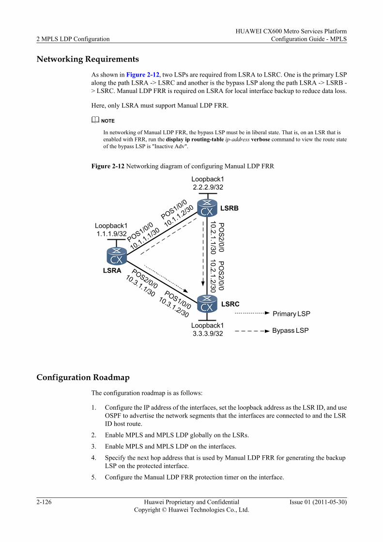
Networking Requirements
As shown in Figure 2-12, two LSPs are required from LSRA to LSRC. One is the primary LSPalong the path LSRA -> LSRC and another is the bypass LSP along the path LSRA -> LSRB -> LSRC. Manual LDP FRR is required on LSRA for local interface backup to reduce data loss.
Here, only LSRA must support Manual LDP FRR.
NOTE
In networking of Manual LDP FRR, the bypass LSP must be in liberal state. That is, on an LSR that isenabled with FRR, run the display ip routing-table ip-address verbose command to view the route stateof the bypass LSP is "Inactive Adv".
Figure 2-12 Networking diagram of configuring Manual LDP FRR
Loopback13.3.3.9/32
Loopback12.2.2.9/32
LSRA
Loopback11.1.1.9/32
LSRB
LSRC
POS2/0/010.3.1.1/30
POS1/0/0
10.1.1.2/30
PO
S2/0/0
10.2.1.1/30
POS1/0/010.3.1.2/30
PO
S2/0/0
10.2.1.2/30
POS1/0/0
10.1.1.1/30
Primary LSP
Bypass LSP
Configuration Roadmap
The configuration roadmap is as follows:
1. Configure the IP address of the interfaces, set the loopback address as the LSR ID, and useOSPF to advertise the network segments that the interfaces are connected to and the LSRID host route.
2. Enable MPLS and MPLS LDP globally on the LSRs.
3. Enable MPLS and MPLS LDP on the interfaces.
4. Specify the next hop address that is used by Manual LDP FRR for generating the backupLSP on the protected interface.
5. Configure the Manual LDP FRR protection timer on the interface.
2 MPLS LDP ConfigurationHUAWEI CX600 Metro Services Platform
Configuration Guide - MPLS
2-126 Huawei Proprietary and ConfidentialCopyright © Huawei Technologies Co., Ltd.
Issue 01 (2011-05-30)
Data PreparationTo complete the configuration, you need the following data:
l IP address of the interfaces, OSPF process ID, and area IDl Policy for triggering the establishment of LSPsl Next hop address of the backup LSPl Value of Manual LDP FRR protection timer
Procedure
Step 1 Configure the IP address for each interface.
Configure the IP address and mask for each interface, including each Loopback interface asshown in Figure 2-12. The detailed configuration is not mentioned here.
Step 2 Configure OSPF to advertise the LSR ID host route and network segments that the interfacesare connected to.
# Configure LSRA.
<LSRA> system-view[LSRA] ospf 1[LSRA-ospf-1] area 0[LSRA-ospf-1-area-0.0.0.0] network 1.1.1.9 0.0.0.0[LSRA-ospf-1-area-0.0.0.0] network 10.1.1.0 0.0.0.3[LSRA-ospf-1-area-0.0.0.0] network 10.3.1.0 0.0.0.3[LSRA-ospf-1-area-0.0.0.0] quit[LSRA-ospf-1] quit
# Configure LSRB.
<LSRB> system-view[LSRB] ospf 1[LSRB-ospf-1] area 0[LSRB-ospf-1-area-0.0.0.0] network 2.2.2.9 0.0.0.0[LSRB-ospf-1-area-0.0.0.0] network 10.1.1.0 0.0.0.3[LSRB-ospf-1-area-0.0.0.0] network 10.2.1.0 0.0.0.3[LSRB-ospf-1-area-0.0.0.0] quit[LSRB-ospf-1] quit
# Configure LSRC.
<LSRC> system-view[LSRC] ospf 1[LSRC-ospf-1] area 0[LSRC-ospf-1-area-0.0.0.0] network 3.3.3.9 0.0.0.0[LSRC-ospf-1-area-0.0.0.0] network 10.3.1.0 0.0.0.3[LSRC-ospf-1-area-0.0.0.0] network 10.2.1.0 0.0.0.3[LSRC-ospf-1-area-0.0.0.0] quit[LSRC-ospf-1] quit
After the configuration, run the display ip routing-table command on each LSR, and you canview that the LSRs learn the routes from each other.
Take the display on LSRA as an example.
<LSRA> display ip routing-tableRoute Flags: R - relay, D - download to fib------------------------------------------------------------------------------Routing Tables: Public Destinations : 12 Routes : 13Destination/Mask Proto Pre Cost Flags NextHop Interface 1.1.1.9/32 Direct 0 0 D 127.0.0.1 InLoopBack0
HUAWEI CX600 Metro Services PlatformConfiguration Guide - MPLS 2 MPLS LDP Configuration
Issue 01 (2011-05-30) Huawei Proprietary and ConfidentialCopyright © Huawei Technologies Co., Ltd.
2-127
2.2.2.9/32 OSPF 10 2 D 10.1.1.2 Pos1/0/0 3.3.3.9/32 OSPF 10 2 D 10.3.1.2 Pos2/0/0 10.1.1.0/30 Direct 0 0 D 10.1.1.1 Pos1/0/0 10.1.1.1/32 Direct 0 0 D 127.0.0.1 InLoopBack0 10.1.1.2/32 Direct 0 0 D 10.1.1.2 Pos1/0/0 10.2.1.0/30 OSPF 10 2 D 10.3.1.2 Pos2/0/0 OSPF 10 2 D 10.1.1.2 Pos1/0/0 10.3.1.0/30 Direct 0 0 D 10.3.1.1 Pos2/0/0 10.3.1.1/32 Direct 0 0 D 127.0.0.1 InLoopBack0 10.3.1.2/32 Direct 0 0 D 10.3.1.2 Pos2/0/0 127.0.0.0/8 Direct 0 0 D 127.0.0.1 InLoopBack0 127.0.0.1/32 Direct 0 0 D 127.0.0.1 InLoopBack0
Step 3 Configure the MPLS and MPLS LDP functions on the nodes globally and on the interfaces toforward the MPLS traffic over the network.
# Configure LSRA.
[LSRA] mpls lsr-id 1.1.1.9[LSRA] mpls[LSRA-mpls] quit[LSRA] mpls ldp[LSRA-mpls-ldp] quit[LSRA] interface pos 1/0/0[LSRA-Pos1/0/0] mpls[LSRA-Pos1/0/0] mpls ldp[LSRA-Pos1/0/0] quit[LSRA] interface pos 2/0/0[LSRA-Pos2/0/0] mpls[LSRA-Pos2/0/0] mpls ldp[LSRA-Pos2/0/0] quit
# Configure LSRB.
[LSRB] mpls lsr-id 2.2.2.9[LSRB] mpls[LSRB-mpls] quit[LSRB] mpls ldp[LSRB-mpls-ldp] quit[LSRB] interface pos 1/0/0[LSRB-Pos1/0/0] mpls[LSRB-Pos1/0/0] mpls ldp[LSRB-Pos1/0/0] quit[LSRB] interface pos 2/0/0[LSRB-Pos2/0/0] mpls[LSRB-Pos2/0/0] mpls ldp[LSRB-Pos2/0/0] quit
# Configure LSRC.
[LSRC] mpls lsr-id 3.3.3.9[LSRC] mpls[LSRC-mpls] quit[LSRC] mpls ldp[LSRC-mpls-ldp] quit[LSRC] interface pos 1/0/0[LSRC-Pos1/0/0] mpls[LSRC-Pos1/0/0] mpls ldp[LSRC-Pos1/0/0] quit[LSRC] interface pos 2/0/0[LSRC-Pos2/0/0] mpls[LSRC-Pos2/0/0] mpls ldp[LSRC-Pos2/0/0] quit
After the configuration, LDP sessions are established between neighboring LSRs. Run thedisplay mpls ldp session command on each LSR, and you can view that Status is displayed asOperational.
Take the display on LSRA as an example.
2 MPLS LDP ConfigurationHUAWEI CX600 Metro Services Platform
Configuration Guide - MPLS
2-128 Huawei Proprietary and ConfidentialCopyright © Huawei Technologies Co., Ltd.
Issue 01 (2011-05-30)
<LSRA> display mpls ldp session LDP Session(s) in Public Network Codes: LAM(Label Advertisement Mode), SsnAge Unit(DDDD:HH:MM) A '*' before a session means the session is being deleted. ------------------------------------------------------------------------------ PeerID Status LAM SsnRole SsnAge KASent/Rcv ------------------------------------------------------------------------------ 2.2.2.9:0 Operational DU Passive 0000:00:01 8/8 3.3.3.9:0 Operational DU Passive 0000:00:01 6/6 ------------------------------------------------------------------------------ TOTAL: 2 session(s) Found.
Step 4 Enable Manual LDP FRR on the POS 2/0/0 on LSRA, and specify the next hop address forgenerating the backup LSP.
# Configure LSRA.
[LSRA] interface pos 2/0/0[LSRA-Pos2/0/0] mpls ldp frr nexthop 10.1.1.2[LSRA-Pos2/0/0] quit
Step 5 Configure Manual LDP FRR protection timer on POS 2/0/0 of LSRA
# Configure LSRA.
[LSRA] interface pos 2/0/0[LSRA-Pos2/0/0] mpls ldp frr timer protect-time 11[LSRA-Pos2/0/0] quit
Step 6 Verify the configuration.
Run the display mpls lsp command on LSRA, and you can view that Manual LDP FRR isenabled on the LSP of LSRC.
<LSRA> display mpls lsp---------------------------------------------------------------------- LSP Information: LDP LSP----------------------------------------------------------------------FEC In/Out Label In/Out IF Vrf Name3.3.3.9/32 NULL/3 -/Pos2/0/0 **LDP FRR** /1025 /Pos1/0/03.3.3.9/32 1025/3 -/Pos2/0/0 **LDP FRR** /1025 /Pos1/0/02.2.2.9/32 NULL/3 -/Pos1/0/02.2.2.9/32 1024/3 -/Pos1/0/0
----End
Configuration Filesl Configuration file of LSRA
#sysname LSRA # mpls lsr-id 1.1.1.9 mpls#mpls ldp#interface Pos1/0/0 link-protocol ppp undo shutdown ip address 10.1.1.1 255.255.255.252mpls mpls ldp#interface Pos2/0/0
HUAWEI CX600 Metro Services PlatformConfiguration Guide - MPLS 2 MPLS LDP Configuration
Issue 01 (2011-05-30) Huawei Proprietary and ConfidentialCopyright © Huawei Technologies Co., Ltd.
2-129
link-protocol ppp undo shutdown ip address 10.3.1.1 255.255.255.252mpls mpls ldpmpls ldp frr timer protect-time 11mpls ldp frr nexthop 10.1.1.2#interface LoopBack1 ip address 1.1.1.9 255.255.255.255#ospf 1 area 0.0.0.0 network 1.1.1.9 0.0.0.0 network 10.1.1.0 0.0.0.3 network 10.3.1.0 0.0.0.3#return
l Configuration file of LSRB#sysname LSRB#mpls lsr-id 2.2.2.9 mpls#mpls ldp#interface Pos1/0/0 link-protocol ppp undo shutdown ip address 10.1.1.2 255.255.255.252mpls mpls ldp#interface Pos2/0/0 link-protocol ppp undo shutdown ip address 10.2.1.1 255.255.255.252mpls mpls ldp#interface LoopBack1 ip address 2.2.2.9 255.255.255.255#ospf 1 area 0.0.0.0 network 2.2.2.9 0.0.0.0 network 10.1.1.0 0.0.0.3 network 10.2.1.0 0.0.0.3#return
l Configuration file of LSRC#sysname LSRC#mpls lsr-id 3.3.3.9 mpls#mpls ldp#interface Pos1/0/0 link-protocol ppp undo shutdown ip address 10.3.1.2 255.255.255.252mpls mpls ldp#interface Pos2/0/0
2 MPLS LDP ConfigurationHUAWEI CX600 Metro Services Platform
Configuration Guide - MPLS
2-130 Huawei Proprietary and ConfidentialCopyright © Huawei Technologies Co., Ltd.
Issue 01 (2011-05-30)
link-protocol ppp undo shutdown ip address 10.2.1.2 255.255.255.252mpls mpls ldp#interface LoopBack1 ip address 3.3.3.9 255.255.255.255#ospf 1 area 0.0.0.0 network 3.3.3.9 0.0.0.0 network 10.3.1.0 0.0.0.3 network 10.2.1.0 0.0.0.3#Return
2.15.12 Example for Configuring LDP Auto FRRThis section provides an example for configuring LDP Auto FRR, which consists of enablingglobal MPLS and MPLS LDP and IS-IS Auto FRR.
Networking RequirementsWith the development of networks, new services that have stringent requirements for real-timetransmission are emerging, for example, Voice over IP (VoIP) and on-line video services. Alarge number of services are based on VPN. Currently, VPN services are generally implementedby using LDP tunnels. In case of data loss due to faults over the link, these services will beseriously affected.
The Manual LDP FRR is a technique that ensures that when a fault occurs, service traffic on thepublic network is forwarded along the backup LSP before routes are converged and a newprimary LSP is established. This mechanism ensures that the service interruption lasts for onlyas long as it takes the fault to be detected and traffic to be switched to the backup LSP. Therefore,packet loss lasts for less than 50 ms. But the time that is required for VPN services to be switchedto a new LSP after routes convergence is completed depends on the actual VPN implementation.This means that the speed at which VPN services are switched to the new primary LSP must beraised so as to ensure that VPN services are interrupted for less than 50 ms. This issue can besolved by configuring LDP Auto FRR.
As shown in Figure 2-13, the primary and backup LSPs are set up between LSRA and LSRC.The primary LSP is along the path from LSRA to LSRC, and the backup LSP is along the pathLSRA -> LSRB -> LSRC. When the primary LSP becomes faulty, traffic must be rapidlyswitched to the backup LSP. After LDP Auto FRR is configured on LSRA, in case of a faultover the link, a backup LSP is automatically set up to reduce traffic loss.
HUAWEI CX600 Metro Services PlatformConfiguration Guide - MPLS 2 MPLS LDP Configuration
Issue 01 (2011-05-30) Huawei Proprietary and ConfidentialCopyright © Huawei Technologies Co., Ltd.
2-131
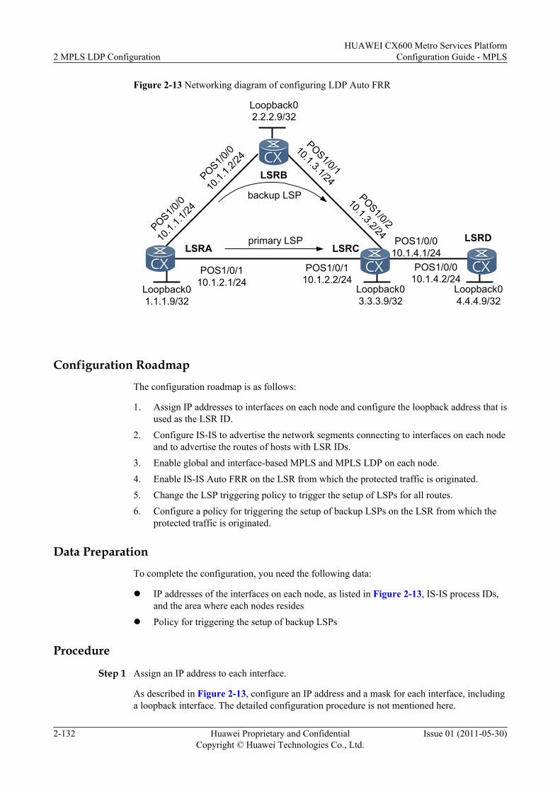
Figure 2-13 Networking diagram of configuring LDP Auto FRR
LSRC
POS1/0/110.1.2.1/24
POS1/0/110.1.2.2/24
LSRALSRDPOS1/0/0
10.1.4.1/24POS1/0/0
10.1.4.2/24Loopback01.1.1.9/32
Loopback03.3.3.9/32
Loopback04.4.4.9/32
POS1/0/0
10.1.
1.1/24
POS1/0/0
10.1.
1.2/24
POS1/0/1
10.1.3.1/24
POS1/0/2
10.1.3.2/24LSRB
Loopback02.2.2.9/32
primary LSP
backup LSP
Configuration Roadmap
The configuration roadmap is as follows:
1. Assign IP addresses to interfaces on each node and configure the loopback address that isused as the LSR ID.
2. Configure IS-IS to advertise the network segments connecting to interfaces on each nodeand to advertise the routes of hosts with LSR IDs.
3. Enable global and interface-based MPLS and MPLS LDP on each node.4. Enable IS-IS Auto FRR on the LSR from which the protected traffic is originated.5. Change the LSP triggering policy to trigger the setup of LSPs for all routes.6. Configure a policy for triggering the setup of backup LSPs on the LSR from which the
protected traffic is originated.
Data Preparation
To complete the configuration, you need the following data:
l IP addresses of the interfaces on each node, as listed in Figure 2-13, IS-IS process IDs,and the area where each nodes resides
l Policy for triggering the setup of backup LSPs
Procedure
Step 1 Assign an IP address to each interface.
As described in Figure 2-13, configure an IP address and a mask for each interface, includinga loopback interface. The detailed configuration procedure is not mentioned here.
2 MPLS LDP ConfigurationHUAWEI CX600 Metro Services Platform
Configuration Guide - MPLS
2-132 Huawei Proprietary and ConfidentialCopyright © Huawei Technologies Co., Ltd.
Issue 01 (2011-05-30)
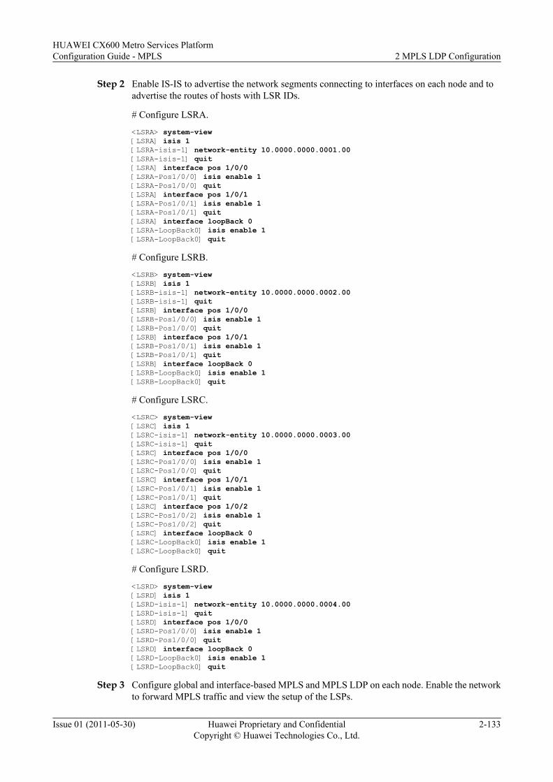
Step 2 Enable IS-IS to advertise the network segments connecting to interfaces on each node and toadvertise the routes of hosts with LSR IDs.
# Configure LSRA.
<LSRA> system-view[LSRA] isis 1[LSRA-isis-1] network-entity 10.0000.0000.0001.00[LSRA-isis-1] quit[LSRA] interface pos 1/0/0[LSRA-Pos1/0/0] isis enable 1[LSRA-Pos1/0/0] quit[LSRA] interface pos 1/0/1[LSRA-Pos1/0/1] isis enable 1[LSRA-Pos1/0/1] quit[LSRA] interface loopBack 0[LSRA-LoopBack0] isis enable 1[LSRA-LoopBack0] quit
# Configure LSRB.
<LSRB> system-view[LSRB] isis 1[LSRB-isis-1] network-entity 10.0000.0000.0002.00[LSRB-isis-1] quit[LSRB] interface pos 1/0/0[LSRB-Pos1/0/0] isis enable 1[LSRB-Pos1/0/0] quit[LSRB] interface pos 1/0/1[LSRB-Pos1/0/1] isis enable 1[LSRB-Pos1/0/1] quit[LSRB] interface loopBack 0[LSRB-LoopBack0] isis enable 1[LSRB-LoopBack0] quit
# Configure LSRC.
<LSRC> system-view[LSRC] isis 1[LSRC-isis-1] network-entity 10.0000.0000.0003.00[LSRC-isis-1] quit[LSRC] interface pos 1/0/0[LSRC-Pos1/0/0] isis enable 1[LSRC-Pos1/0/0] quit[LSRC] interface pos 1/0/1[LSRC-Pos1/0/1] isis enable 1[LSRC-Pos1/0/1] quit[LSRC] interface pos 1/0/2[LSRC-Pos1/0/2] isis enable 1[LSRC-Pos1/0/2] quit[LSRC] interface loopBack 0[LSRC-LoopBack0] isis enable 1[LSRC-LoopBack0] quit
# Configure LSRD.
<LSRD> system-view[LSRD] isis 1[LSRD-isis-1] network-entity 10.0000.0000.0004.00[LSRD-isis-1] quit[LSRD] interface pos 1/0/0[LSRD-Pos1/0/0] isis enable 1[LSRD-Pos1/0/0] quit[LSRD] interface loopBack 0[LSRD-LoopBack0] isis enable 1[LSRD-LoopBack0] quit
Step 3 Configure global and interface-based MPLS and MPLS LDP on each node. Enable the networkto forward MPLS traffic and view the setup of the LSPs.
HUAWEI CX600 Metro Services PlatformConfiguration Guide - MPLS 2 MPLS LDP Configuration
Issue 01 (2011-05-30) Huawei Proprietary and ConfidentialCopyright © Huawei Technologies Co., Ltd.
2-133
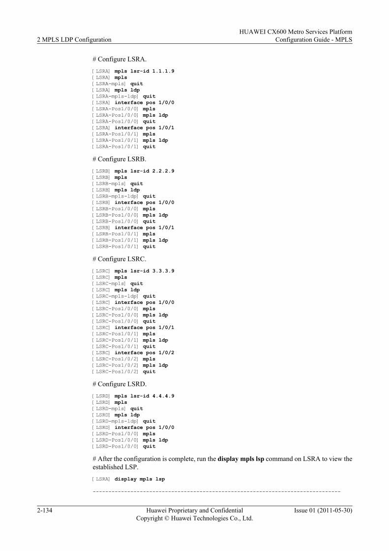
# Configure LSRA.
[LSRA] mpls lsr-id 1.1.1.9[LSRA] mpls[LSRA-mpls] quit[LSRA] mpls ldp[LSRA-mpls-ldp] quit[LSRA] interface pos 1/0/0[LSRA-Pos1/0/0] mpls[LSRA-Pos1/0/0] mpls ldp[LSRA-Pos1/0/0] quit[LSRA] interface pos 1/0/1[LSRA-Pos1/0/1] mpls[LSRA-Pos1/0/1] mpls ldp[LSRA-Pos1/0/1] quit
# Configure LSRB.
[LSRB] mpls lsr-id 2.2.2.9[LSRB] mpls[LSRB-mpls] quit[LSRB] mpls ldp[LSRB-mpls-ldp] quit[LSRB] interface pos 1/0/0[LSRB-Pos1/0/0] mpls[LSRB-Pos1/0/0] mpls ldp[LSRB-Pos1/0/0] quit[LSRB] interface pos 1/0/1[LSRB-Pos1/0/1] mpls[LSRB-Pos1/0/1] mpls ldp[LSRB-Pos1/0/1] quit
# Configure LSRC.
[LSRC] mpls lsr-id 3.3.3.9[LSRC] mpls[LSRC-mpls] quit[LSRC] mpls ldp[LSRC-mpls-ldp] quit[LSRC] interface pos 1/0/0[LSRC-Pos1/0/0] mpls[LSRC-Pos1/0/0] mpls ldp[LSRC-Pos1/0/0] quit[LSRC] interface pos 1/0/1[LSRC-Pos1/0/1] mpls[LSRC-Pos1/0/1] mpls ldp[LSRC-Pos1/0/1] quit[LSRC] interface pos 1/0/2[LSRC-Pos1/0/2] mpls[LSRC-Pos1/0/2] mpls ldp[LSRC-Pos1/0/2] quit
# Configure LSRD.
[LSRD] mpls lsr-id 4.4.4.9[LSRD] mpls[LSRD-mpls] quit[LSRD] mpls ldp[LSRD-mpls-ldp] quit[LSRD] interface pos 1/0/0[LSRD-Pos1/0/0] mpls[LSRD-Pos1/0/0] mpls ldp[LSRD-Pos1/0/0] quit
# After the configuration is complete, run the display mpls lsp command on LSRA to view theestablished LSP.
[LSRA] display mpls lsp
-------------------------------------------------------------------------------
2 MPLS LDP ConfigurationHUAWEI CX600 Metro Services Platform
Configuration Guide - MPLS
2-134 Huawei Proprietary and ConfidentialCopyright © Huawei Technologies Co., Ltd.
Issue 01 (2011-05-30)
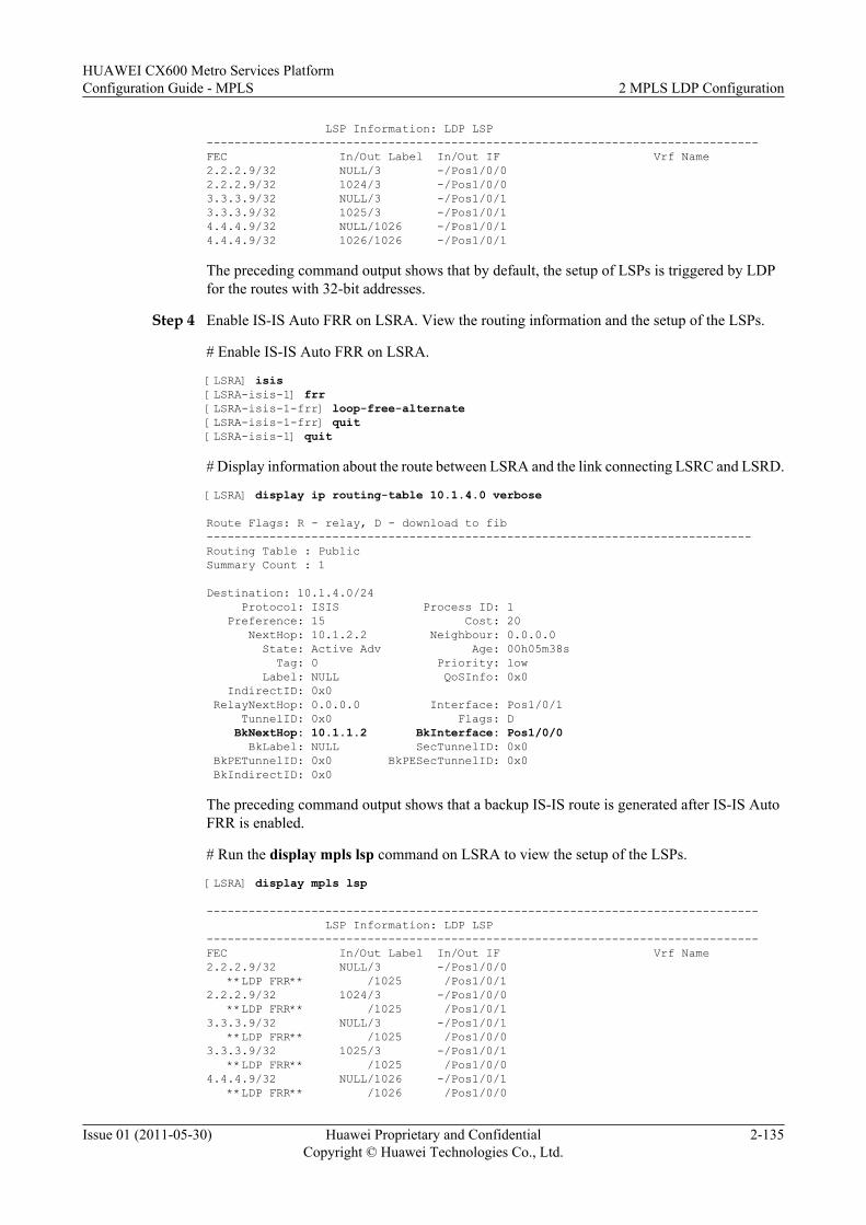
LSP Information: LDP LSP-------------------------------------------------------------------------------FEC In/Out Label In/Out IF Vrf Name2.2.2.9/32 NULL/3 -/Pos1/0/02.2.2.9/32 1024/3 -/Pos1/0/03.3.3.9/32 NULL/3 -/Pos1/0/13.3.3.9/32 1025/3 -/Pos1/0/14.4.4.9/32 NULL/1026 -/Pos1/0/14.4.4.9/32 1026/1026 -/Pos1/0/1
The preceding command output shows that by default, the setup of LSPs is triggered by LDPfor the routes with 32-bit addresses.
Step 4 Enable IS-IS Auto FRR on LSRA. View the routing information and the setup of the LSPs.
# Enable IS-IS Auto FRR on LSRA.
[LSRA] isis[LSRA-isis-1] frr[LSRA-isis-1-frr] loop-free-alternate[LSRA-isis-1-frr] quit[LSRA-isis-1] quit
# Display information about the route between LSRA and the link connecting LSRC and LSRD.
[LSRA] display ip routing-table 10.1.4.0 verbose
Route Flags: R - relay, D - download to fib------------------------------------------------------------------------------Routing Table : PublicSummary Count : 1
Destination: 10.1.4.0/24 Protocol: ISIS Process ID: 1 Preference: 15 Cost: 20 NextHop: 10.1.2.2 Neighbour: 0.0.0.0 State: Active Adv Age: 00h05m38s Tag: 0 Priority: low Label: NULL QoSInfo: 0x0 IndirectID: 0x0 RelayNextHop: 0.0.0.0 Interface: Pos1/0/1 TunnelID: 0x0 Flags: D BkNextHop: 10.1.1.2 BkInterface: Pos1/0/0 BkLabel: NULL SecTunnelID: 0x0 BkPETunnelID: 0x0 BkPESecTunnelID: 0x0 BkIndirectID: 0x0
The preceding command output shows that a backup IS-IS route is generated after IS-IS AutoFRR is enabled.
# Run the display mpls lsp command on LSRA to view the setup of the LSPs.
[LSRA] display mpls lsp
------------------------------------------------------------------------------- LSP Information: LDP LSP-------------------------------------------------------------------------------FEC In/Out Label In/Out IF Vrf Name2.2.2.9/32 NULL/3 -/Pos1/0/0 **LDP FRR** /1025 /Pos1/0/12.2.2.9/32 1024/3 -/Pos1/0/0 **LDP FRR** /1025 /Pos1/0/13.3.3.9/32 NULL/3 -/Pos1/0/1 **LDP FRR** /1025 /Pos1/0/03.3.3.9/32 1025/3 -/Pos1/0/1 **LDP FRR** /1025 /Pos1/0/04.4.4.9/32 NULL/1026 -/Pos1/0/1 **LDP FRR** /1026 /Pos1/0/0
HUAWEI CX600 Metro Services PlatformConfiguration Guide - MPLS 2 MPLS LDP Configuration
Issue 01 (2011-05-30) Huawei Proprietary and ConfidentialCopyright © Huawei Technologies Co., Ltd.
2-135
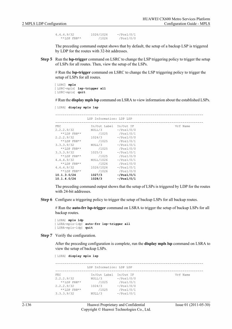
4.4.4.9/32 1026/1026 -/Pos1/0/1 **LDP FRR** /1026 /Pos1/0/0
The preceding command output shows that by default, the setup of a backup LSP is triggeredby LDP for the routes with 32-bit addresses.
Step 5 Run the lsp-trigger command on LSRC to change the LSP triggering policy to trigger the setupof LSPs for all routes. Then, view the setup of the LSPs.
# Run the lsp-trigger command on LSRC to change the LSP triggering policy to trigger thesetup of LSPs for all routes.
[LSRC] mpls[LSRC-mpls] lsp-trigger all[LSRC-mpls] quit
# Run the display mpls lsp command on LSRA to view information about the established LSPs.
[LSRA] display mpls lsp
------------------------------------------------------------------------------- LSP Information: LDP LSP-------------------------------------------------------------------------------FEC In/Out Label In/Out IF Vrf Name2.2.2.9/32 NULL/3 -/Pos1/0/0 **LDP FRR** /1025 /Pos1/0/12.2.2.9/32 1024/3 -/Pos1/0/0 **LDP FRR** /1025 /Pos1/0/13.3.3.9/32 NULL/3 -/Pos1/0/1 **LDP FRR** /1025 /Pos1/0/03.3.3.9/32 1025/3 -/Pos1/0/1 **LDP FRR** /1025 /Pos1/0/04.4.4.9/32 NULL/1026 -/Pos1/0/1 **LDP FRR** /1026 /Pos1/0/04.4.4.9/32 1026/1026 -/Pos1/0/1 **LDP FRR** /1026 /Pos1/0/010.1.3.0/24 1027/3 -/Pos1/0/110.1.4.0/24 1028/3 -/Pos1/0/1
The preceding command output shows that the setup of LSPs is triggered by LDP for the routeswith 24-bit addresses.
Step 6 Configure a triggering policy to trigger the setup of backup LSPs for all backup routes.
# Run the auto-frr lsp-trigger command on LSRA to trigger the setup of backup LSPs for allbackup routes.
[LSRA] mpls ldp[LSRA-mpls-ldp] auto-frr lsp-trigger all[LSRA-mpls-ldp] quit
Step 7 Verify the configuration.
After the preceding configuration is complete, run the display mpls lsp command on LSRA toview the setup of backup LSPs.
[LSRA] display mpls lsp
------------------------------------------------------------------------------- LSP Information: LDP LSP-------------------------------------------------------------------------------FEC In/Out Label In/Out IF Vrf Name2.2.2.9/32 NULL/3 -/Pos1/0/0 **LDP FRR** /1025 /Pos1/0/12.2.2.9/32 1024/3 -/Pos1/0/0 **LDP FRR** /1025 /Pos1/0/13.3.3.9/32 NULL/3 -/Pos1/0/1
2 MPLS LDP ConfigurationHUAWEI CX600 Metro Services Platform
Configuration Guide - MPLS
2-136 Huawei Proprietary and ConfidentialCopyright © Huawei Technologies Co., Ltd.
Issue 01 (2011-05-30)
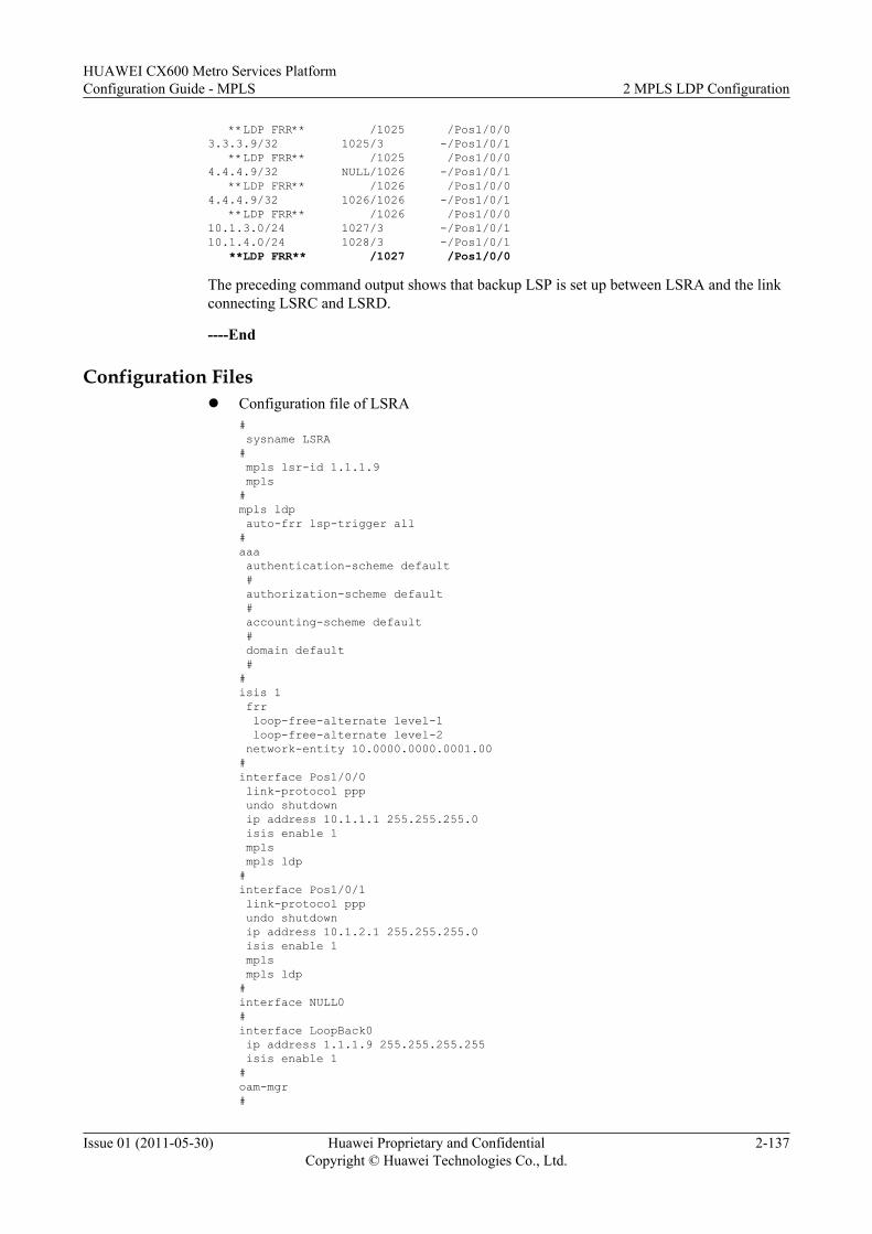
**LDP FRR** /1025 /Pos1/0/03.3.3.9/32 1025/3 -/Pos1/0/1 **LDP FRR** /1025 /Pos1/0/04.4.4.9/32 NULL/1026 -/Pos1/0/1 **LDP FRR** /1026 /Pos1/0/04.4.4.9/32 1026/1026 -/Pos1/0/1 **LDP FRR** /1026 /Pos1/0/010.1.3.0/24 1027/3 -/Pos1/0/110.1.4.0/24 1028/3 -/Pos1/0/1 **LDP FRR** /1027 /Pos1/0/0
The preceding command output shows that backup LSP is set up between LSRA and the linkconnecting LSRC and LSRD.
----End
Configuration Filesl Configuration file of LSRA
# sysname LSRA# mpls lsr-id 1.1.1.9 mpls#mpls ldp auto-frr lsp-trigger all#aaa authentication-scheme default # authorization-scheme default # accounting-scheme default # domain default ##isis 1 frr loop-free-alternate level-1 loop-free-alternate level-2 network-entity 10.0000.0000.0001.00#interface Pos1/0/0 link-protocol ppp undo shutdown ip address 10.1.1.1 255.255.255.0 isis enable 1 mpls mpls ldp#interface Pos1/0/1 link-protocol ppp undo shutdown ip address 10.1.2.1 255.255.255.0 isis enable 1 mpls mpls ldp#interface NULL0#interface LoopBack0 ip address 1.1.1.9 255.255.255.255 isis enable 1#oam-mgr#
HUAWEI CX600 Metro Services PlatformConfiguration Guide - MPLS 2 MPLS LDP Configuration
Issue 01 (2011-05-30) Huawei Proprietary and ConfidentialCopyright © Huawei Technologies Co., Ltd.
2-137
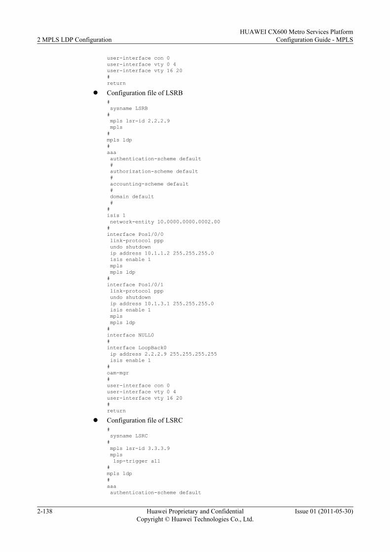
user-interface con 0user-interface vty 0 4user-interface vty 16 20#return
l Configuration file of LSRB# sysname LSRB# mpls lsr-id 2.2.2.9 mpls#mpls ldp#aaa authentication-scheme default # authorization-scheme default # accounting-scheme default # domain default ##isis 1 network-entity 10.0000.0000.0002.00#interface Pos1/0/0 link-protocol ppp undo shutdown ip address 10.1.1.2 255.255.255.0 isis enable 1 mpls mpls ldp#interface Pos1/0/1 link-protocol ppp undo shutdown ip address 10.1.3.1 255.255.255.0 isis enable 1 mpls mpls ldp#interface NULL0#interface LoopBack0 ip address 2.2.2.9 255.255.255.255 isis enable 1#oam-mgr#user-interface con 0user-interface vty 0 4user-interface vty 16 20#return
l Configuration file of LSRC# sysname LSRC# mpls lsr-id 3.3.3.9 mpls lsp-trigger all#mpls ldp#aaa authentication-scheme default
2 MPLS LDP ConfigurationHUAWEI CX600 Metro Services Platform
Configuration Guide - MPLS
2-138 Huawei Proprietary and ConfidentialCopyright © Huawei Technologies Co., Ltd.
Issue 01 (2011-05-30)
# authorization-scheme default # accounting-scheme default # domain default ##isis 1 network-entity 10.0000.0000.0003.00#interface Pos1/0/0 link-protocol ppp undo shutdown ip address 10.1.4.1 255.255.255.0 isis enable 1 mpls mpls ldp#interface Pos1/0/1 link-protocol ppp undo shutdown ip address 10.1.2.2 255.255.255.0 isis enable 1 mpls mpls ldp#interface Pos1/0/2 link-protocol ppp undo shutdown ip address 10.1.3.2 255.255.255.0 isis enable 1 mpls mpls ldp#interface NULL0#interface LoopBack0 ip address 3.3.3.9 255.255.255.255 isis enable 1#oam-mgr#user-interface con 0user-interface vty 0 4user-interface vty 16 20#return
l Configuration file of LSRD# sysname LSRD# mpls lsr-id 4.4.4.9 mpls#mpls ldp#aaa authentication-scheme default # authorization-scheme default # accounting-scheme default # domain default ##isis 1 network-entity 10.0000.0000.0004.00
HUAWEI CX600 Metro Services PlatformConfiguration Guide - MPLS 2 MPLS LDP Configuration
Issue 01 (2011-05-30) Huawei Proprietary and ConfidentialCopyright © Huawei Technologies Co., Ltd.
2-139
#interface Pos1/0/0 link-protocol ppp undo shutdown ip address 10.1.4.2 255.255.255.0 isis enable 1 mpls mpls ldp#interface NULL0#interface LoopBack0 ip address 4.4.4.9 255.255.255.255 isis enable 1#oam-mgr#user-interface con 0user-interface vty 0 4user-interface vty 16 20#return
2.15.13 Example for Configuring Synchronization Between LDPand IGP
This section provides an example for configuring LDP and IGP synchronization, which consistsof enabling MPLS and MPLS LDP on each device and each interface and configuring theinterfaces of both ends of the link between the crossing node of active and standby links and theLDP neighboring node.
Networking RequirementsAs shown in Figure 2-14, two links are established between PE1 and PE2. The link PE1 -> P1-> P2 -> PE2 is an active link and the link PE1 -> P1 -> P3 -> PE2 is a standby link.
Configure synchronization between LDP and IGP on interfaces of P1 and P2. P1 and P2 are thecrossing node of active and standby links and the LDP neighbor node of the active linkrespectively. After the active link recovers from the fault, configuring synchronization canshorten the time of traffic switch from the standby link to the active link and limit the time withinmilliseconds.
2 MPLS LDP ConfigurationHUAWEI CX600 Metro Services Platform
Configuration Guide - MPLS
2-140 Huawei Proprietary and ConfidentialCopyright © Huawei Technologies Co., Ltd.
Issue 01 (2011-05-30)
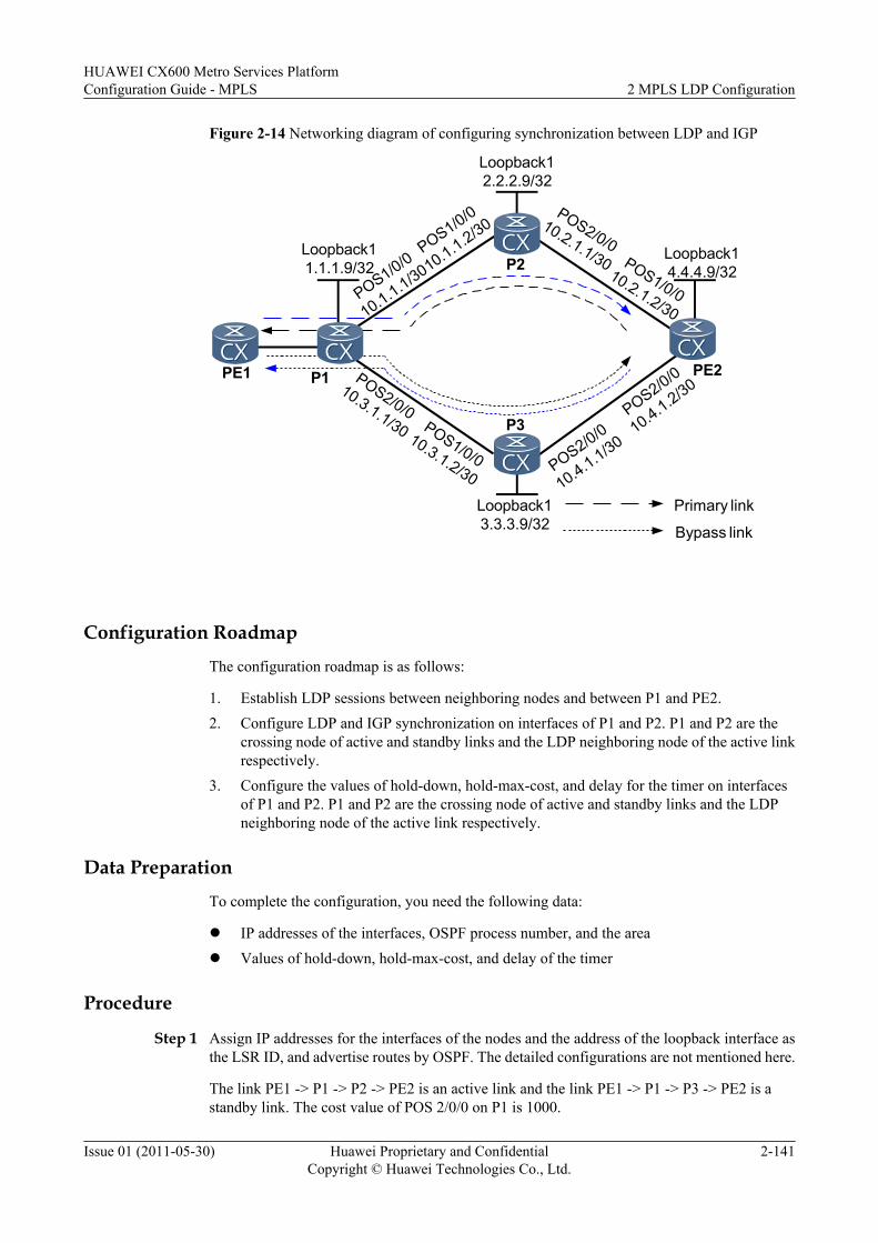
Figure 2-14 Networking diagram of configuring synchronization between LDP and IGP
Loopback13.3.3.9/32
Loopback12.2.2.9/32
P1
Loopback11.1.1.9/32
Loopback14.4.4.9/32P2
P3
PE2
POS1/0/0
10.1.1.1/30
POS2/0/010.3.1.1/30
POS1/0/0
10.1.1.2/30POS2/0/0
10.2.1.1/30
POS1/0/010.3.1.2/30 POS2/0/0
10.4.1.1/30
POS1/0/010.2.1.2/30
POS2/0/0
10.4.1.2/30
Primary link
Bypass link
PE1
Configuration Roadmap
The configuration roadmap is as follows:
1. Establish LDP sessions between neighboring nodes and between P1 and PE2.2. Configure LDP and IGP synchronization on interfaces of P1 and P2. P1 and P2 are the
crossing node of active and standby links and the LDP neighboring node of the active linkrespectively.
3. Configure the values of hold-down, hold-max-cost, and delay for the timer on interfacesof P1 and P2. P1 and P2 are the crossing node of active and standby links and the LDPneighboring node of the active link respectively.
Data Preparation
To complete the configuration, you need the following data:
l IP addresses of the interfaces, OSPF process number, and the areal Values of hold-down, hold-max-cost, and delay of the timer
Procedure
Step 1 Assign IP addresses for the interfaces of the nodes and the address of the loopback interface asthe LSR ID, and advertise routes by OSPF. The detailed configurations are not mentioned here.
The link PE1 -> P1 -> P2 -> PE2 is an active link and the link PE1 -> P1 -> P3 -> PE2 is astandby link. The cost value of POS 2/0/0 on P1 is 1000.
HUAWEI CX600 Metro Services PlatformConfiguration Guide - MPLS 2 MPLS LDP Configuration
Issue 01 (2011-05-30) Huawei Proprietary and ConfidentialCopyright © Huawei Technologies Co., Ltd.
2-141
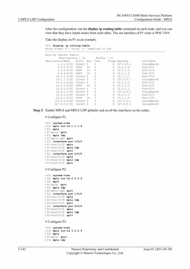
After the configuration, run the display ip routing-table command on each node, and you canview that they have learnt routes from each other. The out interface of P1 route is POS 1/0/0.
Take the display on P1 as an example.
<P1> display ip routing-tableRoute Flags: R - relay, D - download to fib------------------------------------------------------------------------------Routing Tables: Public Destinations : 14 Routes : 14Destination/Mask Proto Pre Cost Flags NextHop Interface 1.1.1.9/32 Direct 0 0 D 127.0.0.1 InLoopBack0 2.2.2.9/32 OSPF 10 2 D 10.1.1.2 Pos1/0/0 3.3.3.9/32 OSPF 10 4 D 10.1.1.2 Pos1/0/0 4.4.4.9/32 OSPF 10 3 D 10.1.1.2 Pos1/0/0 10.1.1.0/30 Direct 0 0 D 10.1.1.1 Pos1/0/0 10.1.1.1/32 Direct 0 0 D 127.0.0.1 InLoopBack0 10.1.1.2/32 Direct 0 0 D 10.1.1.2 Pos1/0/0 10.2.1.0/30 OSPF 10 2 D 10.1.1.2 Pos1/0/0 10.3.1.0/30 Direct 0 0 D 10.3.1.1 Pos2/0/0 10.3.1.1/32 Direct 0 0 D 127.0.0.1 InLoopBack0 10.3.1.2/32 Direct 0 0 D 10.3.1.2 Pos2/0/0 10.4.1.0/30 OSPF 10 3 D 10.1.1.2 Pos1/0/0 127.0.0.0/20 Direct 0 0 D 127.0.0.1 InLoopBack0 127.0.0.1/32 Direct 0 0 D 127.0.0.1 InLoopBack0
Step 2 Enable MPLS and MPLS LDP globally and on all the interfaces on the nodes.
# Configure P1.
<P1> system-view[P1] mpls lsr-id 1.1.1.9[P1] mpls[P1-mpls] quit[P1] mpls ldp[P1-mpls-ldp] quit[P1] interface pos 1/0/0[P1-Pos1/0/0] mpls[P1-Pos1/0/0] mpls ldp[P1-Pos1/0/0] quit[P1] interface pos 2/0/0[P1-Pos2/0/0] mpls[P1-Pos2/0/0] mpls ldp[P1-Pos2/0/0] quit
# Configure P2.
<P2> system-view[P2] mpls lsr-id 2.2.2.9[P2] mpls[P2-mpls] quit[P2] mpls ldp[P2-mpls-ldp] quit[P2] interface pos 1/0/0[P2-Pos1/0/0] mpls[P2-Pos1/0/0] mpls ldp[P2-Pos1/0/0] quit[P2] interface pos 2/0/0[P2-Pos2/0/0] mpls[P2-Pos2/0/0] mpls ldp[P2-Pos2/0/0] quit
# Configure P3.
<P3> system-view[P3] mpls lsr-id 3.3.3.9[P3] mpls[P3-mpls] quit[P3] mpls ldp
2 MPLS LDP ConfigurationHUAWEI CX600 Metro Services Platform
Configuration Guide - MPLS
2-142 Huawei Proprietary and ConfidentialCopyright © Huawei Technologies Co., Ltd.
Issue 01 (2011-05-30)
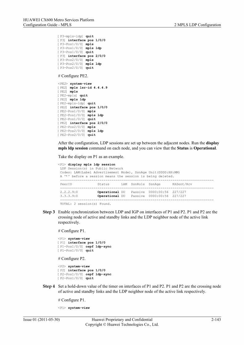
[P3-mpls-ldp] quit[P3] interface pos 1/0/0[P3-Pos1/0/0] mpls[P3-Pos1/0/0] mpls ldp[P3-Pos1/0/0] quit[P3] interface pos 2/0/0[P3-Pos2/0/0] mpls[P3-Pos2/0/0] mpls ldp[P3-Pos2/0/0] quit
# Configure PE2.
<PE2> system-view[PE2] mpls lsr-id 4.4.4.9[PE2] mpls[PE2-mpls] quit[PE2] mpls ldp[PE2-mpls-ldp] quit[PE2] interface pos 1/0/0[PE2-Pos1/0/0] mpls[PE2-Pos1/0/0] mpls ldp[PE2-Pos1/0/0] quit[PE2] interface pos 2/0/0[PE2-Pos2/0/0] mpls[PE2-Pos2/0/0] mpls ldp[PE2-Pos2/0/0] quit
After the configuration, LDP sessions are set up between the adjacent nodes. Run the displaympls ldp session command on each node, and you can view that the Status is Operational.
Take the display on P1 as an example.
<P1> display mpls ldp session LDP Session(s) in Public Network Codes: LAM(Label Advertisement Mode), SsnAge Unit(DDDD:HH:MM) A '*' before a session means the session is being deleted. ------------------------------------------------------------------------------ PeerID Status LAM SsnRole SsnAge KASent/Rcv ------------------------------------------------------------------------------ 2.2.2.9:0 Operational DU Passive 0000:00:56 227/227 3.3.3.9:0 Operational DU Passive 0000:00:56 227/227 ------------------------------------------------------------------------------ TOTAL: 2 session(s) Found.
Step 3 Enable synchronization between LDP and IGP on interfaces of P1 and P2. P1 and P2 are thecrossing node of active and standby links and the LDP neighbor node of the active linkrespectively.
# Configure P1.
<P1> system-view[P1] interface pos 1/0/0[P1-Pos1/0/0] ospf ldp-sync[P1-Pos1/0/0] quit
# Configure P2.
<P2> system-view[P2] interface pos 1/0/0[P2-Pos1/0/0] ospf ldp-sync[P2-Pos1/0/0] quit
Step 4 Set a hold-down value of the timer on interfaces of P1 and P2. P1 and P2 are the crossing nodeof active and standby links and the LDP neighbor node of the active link respectively.
# Configure P1.
<P1> system-view
HUAWEI CX600 Metro Services PlatformConfiguration Guide - MPLS 2 MPLS LDP Configuration
Issue 01 (2011-05-30) Huawei Proprietary and ConfidentialCopyright © Huawei Technologies Co., Ltd.
2-143
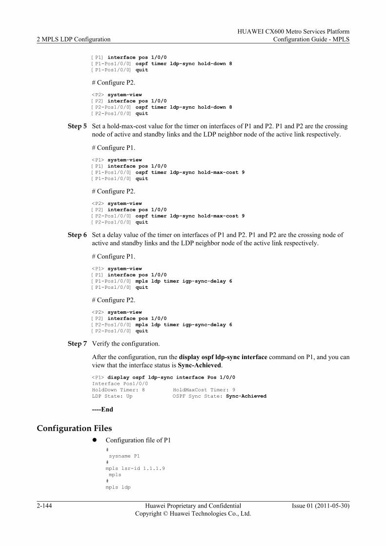
[P1] interface pos 1/0/0[P1-Pos1/0/0] ospf timer ldp-sync hold-down 8[P1-Pos1/0/0] quit
# Configure P2.
<P2> system-view[P2] interface pos 1/0/0[P2-Pos1/0/0] ospf timer ldp-sync hold-down 8[P2-Pos1/0/0] quit
Step 5 Set a hold-max-cost value for the timer on interfaces of P1 and P2. P1 and P2 are the crossingnode of active and standby links and the LDP neighbor node of the active link respectively.
# Configure P1.
<P1> system-view[P1] interface pos 1/0/0[P1-Pos1/0/0] ospf timer ldp-sync hold-max-cost 9[P1-Pos1/0/0] quit
# Configure P2.
<P2> system-view[P2] interface pos 1/0/0[P2-Pos1/0/0] ospf timer ldp-sync hold-max-cost 9[P2-Pos1/0/0] quit
Step 6 Set a delay value of the timer on interfaces of P1 and P2. P1 and P2 are the crossing node ofactive and standby links and the LDP neighbor node of the active link respectively.
# Configure P1.
<P1> system-view[P1] interface pos 1/0/0[P1-Pos1/0/0] mpls ldp timer igp-sync-delay 6[P1-Pos1/0/0] quit
# Configure P2.
<P2> system-view[P2] interface pos 1/0/0[P2-Pos1/0/0] mpls ldp timer igp-sync-delay 6[P2-Pos1/0/0] quit
Step 7 Verify the configuration.
After the configuration, run the display ospf ldp-sync interface command on P1, and you canview that the interface status is Sync-Achieved.
<P1> display ospf ldp-sync interface Pos 1/0/0Interface Pos1/0/0HoldDown Timer: 8 HoldMaxCost Timer: 9LDP State: Up OSPF Sync State: Sync-Achieved
----End
Configuration Filesl Configuration file of P1
# sysname P1#mpls lsr-id 1.1.1.9 mpls#mpls ldp
2 MPLS LDP ConfigurationHUAWEI CX600 Metro Services Platform
Configuration Guide - MPLS
2-144 Huawei Proprietary and ConfidentialCopyright © Huawei Technologies Co., Ltd.
Issue 01 (2011-05-30)
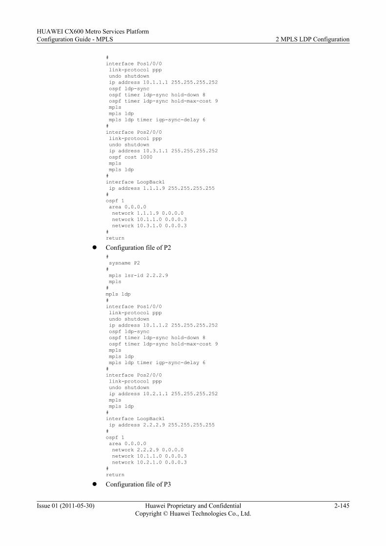
#interface Pos1/0/0 link-protocol ppp undo shutdown ip address 10.1.1.1 255.255.255.252 ospf ldp-sync ospf timer ldp-sync hold-down 8 ospf timer ldp-sync hold-max-cost 9 mpls mpls ldp mpls ldp timer igp-sync-delay 6#interface Pos2/0/0 link-protocol ppp undo shutdown ip address 10.3.1.1 255.255.255.252 ospf cost 1000 mpls mpls ldp#interface LoopBack1 ip address 1.1.1.9 255.255.255.255#ospf 1 area 0.0.0.0 network 1.1.1.9 0.0.0.0 network 10.1.1.0 0.0.0.3 network 10.3.1.0 0.0.0.3#return
l Configuration file of P2# sysname P2# mpls lsr-id 2.2.2.9 mpls#mpls ldp#interface Pos1/0/0 link-protocol ppp undo shutdown ip address 10.1.1.2 255.255.255.252 ospf ldp-sync ospf timer ldp-sync hold-down 8 ospf timer ldp-sync hold-max-cost 9 mpls mpls ldp mpls ldp timer igp-sync-delay 6#interface Pos2/0/0 link-protocol ppp undo shutdown ip address 10.2.1.1 255.255.255.252 mpls mpls ldp#interface LoopBack1 ip address 2.2.2.9 255.255.255.255#ospf 1 area 0.0.0.0 network 2.2.2.9 0.0.0.0 network 10.1.1.0 0.0.0.3 network 10.2.1.0 0.0.0.3#return
l Configuration file of P3
HUAWEI CX600 Metro Services PlatformConfiguration Guide - MPLS 2 MPLS LDP Configuration
Issue 01 (2011-05-30) Huawei Proprietary and ConfidentialCopyright © Huawei Technologies Co., Ltd.
2-145
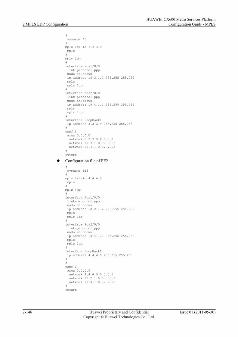
# sysname P3#mpls lsr-id 3.3.3.9 mpls#mpls ldp#interface Pos1/0/0 link-protocol ppp undo shutdown ip address 10.3.1.2 255.255.255.252 mpls mpls ldp#interface Pos2/0/0 link-protocol ppp undo shutdown ip address 10.4.1.1 255.255.255.252 mpls mpls ldp#interface LoopBack1 ip address 3.3.3.9 255.255.255.255#ospf 1 area 0.0.0.0 network 3.3.3.9 0.0.0.0 network 10.3.1.0 0.0.0.3 network 10.4.1.0 0.0.0.3#return
l Configuration file of PE2# sysname PE2#mpls lsr-id 4.4.4.9 mpls#mpls ldp#interface Pos1/0/0 link-protocol ppp undo shutdown ip address 10.2.1.2 255.255.255.252 mpls mpls ldp#interface Pos2/0/0 link-protocol ppp undo shutdown ip address 10.4.1.2 255.255.255.252 mpls mpls ldp#interface LoopBack1 ip address 4.4.4.9 255.255.255.255##ospf 1 area 0.0.0.0 network 4.4.4.9 0.0.0.0 network 10.2.1.0 0.0.0.3 network 10.4.1.0 0.0.0.3#return
2 MPLS LDP ConfigurationHUAWEI CX600 Metro Services Platform
Configuration Guide - MPLS
2-146 Huawei Proprietary and ConfidentialCopyright © Huawei Technologies Co., Ltd.
Issue 01 (2011-05-30)
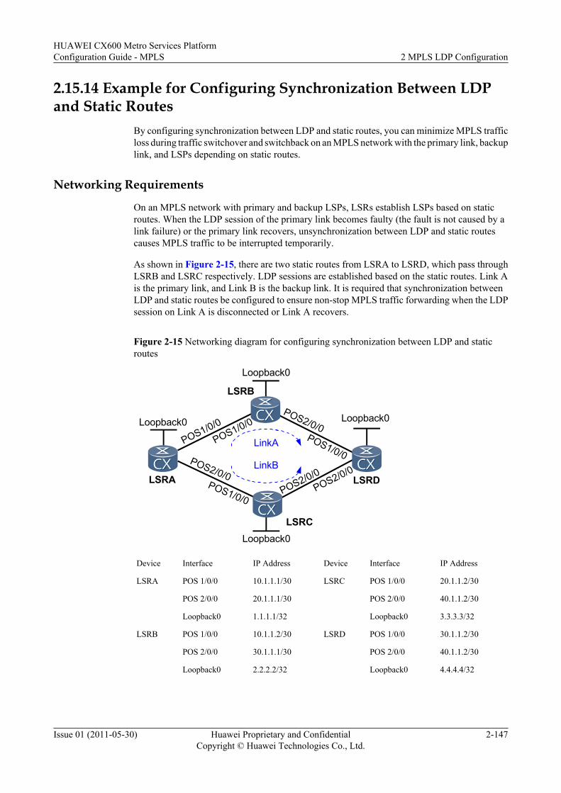
2.15.14 Example for Configuring Synchronization Between LDPand Static Routes
By configuring synchronization between LDP and static routes, you can minimize MPLS trafficloss during traffic switchover and switchback on an MPLS network with the primary link, backuplink, and LSPs depending on static routes.
Networking Requirements
On an MPLS network with primary and backup LSPs, LSRs establish LSPs based on staticroutes. When the LDP session of the primary link becomes faulty (the fault is not caused by alink failure) or the primary link recovers, unsynchronization between LDP and static routescauses MPLS traffic to be interrupted temporarily.
As shown in Figure 2-15, there are two static routes from LSRA to LSRD, which pass throughLSRB and LSRC respectively. LDP sessions are established based on the static routes. Link Ais the primary link, and Link B is the backup link. It is required that synchronization betweenLDP and static routes be configured to ensure non-stop MPLS traffic forwarding when the LDPsession on Link A is disconnected or Link A recovers.
Figure 2-15 Networking diagram for configuring synchronization between LDP and staticroutes
Loopback0
LSRA
LSRB
LSRC
LSRD
Loopback0
POS1/0/0
POS1/0/0
POS2/0/0POS1/0/0
POS2/0/0POS1/0/0
POS2/0/0POS2/0/0
Loopback0
Loopback0
LinkA
LinkB
Device Interface IP Address Device Interface IP Address
LSRA POS 1/0/0 10.1.1.1/30 LSRC POS 1/0/0 20.1.1.2/30
POS 2/0/0 20.1.1.1/30 POS 2/0/0 40.1.1.2/30
Loopback0 1.1.1.1/32 Loopback0 3.3.3.3/32
LSRB POS 1/0/0 10.1.1.2/30 LSRD POS 1/0/0 30.1.1.2/30
POS 2/0/0 30.1.1.1/30 POS 2/0/0 40.1.1.2/30
Loopback0 2.2.2.2/32 Loopback0 4.4.4.4/32
HUAWEI CX600 Metro Services PlatformConfiguration Guide - MPLS 2 MPLS LDP Configuration
Issue 01 (2011-05-30) Huawei Proprietary and ConfidentialCopyright © Huawei Technologies Co., Ltd.
2-147
Configuration RoadmapThe configuration roadmap is as follows:
1. Configure static routes between LSRs to ensure network connectivity.2. Enable MPLS and MPLS LDP in the system view and interface view.3. Configure synchronization between LDP and static routes and verify the configuration.
Data PreparationTo complete the configuration, you need the following data:
l IP addresses of all interfacesl MPLS LSR IDs of LSRsl Value of the Hold-down timer
Procedure
Step 1 Configure an IP address for each interface.
# Configure IP addresses for interfaces according to Figure 2-15. The configuration details arenot described here.
Step 2 Configure static routes on devices to ensure network connectivity.
# On LSRA, configure two static routes with different priorities to LSRD, and on LSRD,configure two static routes with different priorities to LSRA.
# Configure LSRA.
[LSRA] ip route-static 2.2.2.2 32 pos1/0/0[LSRA] ip route-static 3.3.3.3 32 pos2/0/0[LSRA] ip route-static 30.1.1.1 30 pos1/0/0[LSRA] ip route-static 40.1.1.1 30 pos2/0/0[LSRA] ip route-static 4.4.4.4 32 pos1/0/0 preference 40[LSRA] ip route-static 4.4.4.4 32 pos2/0/0 preference 60
# Configure LSRB.
[LSRB] ip route-static 1.1.1.1 32 pos1/0/0[LSRB] ip route-static 4.4.4.4 32 pos2/0/0
# Configure LSRC.
[LSRC] ip route-static 1.1.1.1 32 pos1/0/0[LSRC] ip route-static 4.4.4.4 32 pos2/0/0
# Configure LSRD.
[LSRD] ip route-static 2.2.2.2 32 pos1/0/0[LSRD] ip route-static 3.3.3.3 32 pos2/0/0[LSRD] ip route-static 10.1.1.2 30 pos1/0/0[LSRD] ip route-static 20.1.1.2 30 pos2/0/0[LSRD] ip route-static 1.1.1.1 32 pos1/0/0 preference 40[LSRD] ip route-static 1.1.1.1 32 pos2/0/0 preference 60
# After the preceding configurations, run the display ip routing-table protocol static commandon each LSR. The command output shows the configured static routes. Take the display onLSRA as an example.
[LSRA] display ip routing-table protocol static
2 MPLS LDP ConfigurationHUAWEI CX600 Metro Services Platform
Configuration Guide - MPLS
2-148 Huawei Proprietary and ConfidentialCopyright © Huawei Technologies Co., Ltd.
Issue 01 (2011-05-30)
Route Flags: R - relay, D - download to fib------------------------------------------------------------------------------Public routing table : Static Destinations : 5 Routes : 6 Configured Routes : 6
Static routing table status : <Active> Destinations : 5 Routes : 5
Destination/Mask Proto Pre Cost Flags NextHop Interface
2.2.2.2/32 Static 60 0 D 10.1.1.1 Pos1/0/0 3.3.3.3/32 Static 60 0 D 20.1.1.1 Pos2/0/0 4.4.4.4/32 Static 40 0 D 10.1.1.1 Pos1/0/0 30.1.1.0/30 Static 60 0 D 10.1.1.1 Pos1/0/0 40.1.1.0/30 Static 60 0 D 20.1.1.1 Pos2/0/0
Static routing table status : <Inactive> Destinations : 1 Routes : 1
Destination/Mask Proto Pre Cost Flags NextHop Interface
4.4.4.4/32 Static 60 0 20.1.1.1 Pos2/0/0
Step 3 Enable MPLS LDP and establish LDP LSPs on LSRs.
# Configure LSRA.
[LSRA] mpls lsr-id 1.1.1.1[LSRA] mpls[LSRA-mpls] quit[LSRA] mpls ldp[LSRA-mpls-ldp] quit[LSRA] interface pos1/0/0[LSRA-Pos1/0/0] mpls[LSRA-Pos1/0/0] mpls ldp[LSRA-Pos1/0/0] quit[LSRA] interface pos2/0/0[LSRA-Pos2/0/0] mpls[LSRA-Pos2/0/0] mpls ldp[LSRA-Pos2/0/0] quit
The configurations of LSRB, LSRC, and LSRD are similar to the configuration of LSRA, andare not described here. For configuration details, see "Configuration Files."
# Run the display mpls ldp session command on each LSR. The command output shows thatthe status of LDP sessions is Operational. This indicates that LDP sessions have beenestablished. Take the display on LSRA as an example.
[LSRA] display mpls ldp session LDP Session(s) in Public Network Codes: LAM(Label Advertisement Mode), SsnAge Unit(DDDD:HH:MM) A '*' before a session means the session is being deleted. ------------------------------------------------------------------------------ PeerID Status LAM SsnRole SsnAge KASent/Rcv ------------------------------------------------------------------------------ 2.2.2.2:0 Operational DU Passive 0000:00:00 1/1 3.3.3.3:0 Operational DU Passive 0000:00:02 12/12 ------------------------------------------------------------------------------ TOTAL: 2 session(s) Found.
Step 4 Configure synchronization between LDP and static routes on LSRA and LSRD.
# Configure LSRA.
[LSRA] ip route-static 4.4.4.4 32 pos1/0/0 ldp-sync[LSRA] interface pos1/0/0[LSRA-Pos1/0/0] static-route timer ldp-sync hold-down 20[LSRA-Pos1/0/0] quit
HUAWEI CX600 Metro Services PlatformConfiguration Guide - MPLS 2 MPLS LDP Configuration
Issue 01 (2011-05-30) Huawei Proprietary and ConfidentialCopyright © Huawei Technologies Co., Ltd.
2-149
# Configure LSRD.
[LSRD] ip route-static 1.1.1.1 32 pos1/0/0 ldp-sync[LSRD] interface pos1/0/0[LSRD-Pos1/0/0] static-route timer ldp-sync hold-down 20[LSRD-Pos1/0/0] quit
Step 5 Verify the configuration.
# On LSRA, check the status of the outbound interface of the static route configured withsynchronization between LDP and static routes.
[LSRA] display static-route ldp-syncTotal number of routes enable Ldp-Sync: 1-----------------------------------------------------Interface Pos1/0/0Enable ldp-sync static routes number: 1Static-route ldp-sync holddown timer: 20sSync state: NormalDest = 4.4.4.4, Mask = 32, NextHop = 10.1.1.1.-----------------------------------------------------
The preceding display shows that the status of synchronization between LDP and static routesis Normal. This indicates that synchronization between LDP and static routes has beenconfigured.
l If the LDP session of the primary link (Link A) is disconnected, traffic is immediatelyswitched to the backup link (Link B) to synchronize LDP and static routes. This ensures non-stop traffic forwarding.
l After the primary link recovers, the static route with the next-hop address being 10.1.1.1 isnot preferred immediately. Instead, the static route becomes active only after the LDP sessionof the primary link has been established and the Hold-down timer expires (the timeout periodof the timer is 20 seconds). This synchronizes static routes and LDP, thus ensuring non-stopMPLS traffic forwarding.
----End
Configuration Filesl Configuration file of LSRA
# sysname LSRA# mpls lsr-id 1.1.1.1 mpls#mpls ldp#interface Pos1/0/0 link-protocol ppp ip address 10.1.1.1 255.255.255.252 static-route timer ldp-sync hold-down 20 mpls mpls ldp#interface Pos2/0/0 link-protocol ppp ip address 20.1.1.1 255.255.255.252 mpls mpls ldp#interface loopback0 ip address 1.1.1.1 255.255.255.255# ip route-static 2.2.2.2 255.255.255.255 Pos1/0/0
2 MPLS LDP ConfigurationHUAWEI CX600 Metro Services Platform
Configuration Guide - MPLS
2-150 Huawei Proprietary and ConfidentialCopyright © Huawei Technologies Co., Ltd.
Issue 01 (2011-05-30)
ip route-static 3.3.3.3 255.255.255.255 Pos2/0/0 ip route-static 4.4.4.4 255.255.255.255 Pos1/0/0 preference 40 ldp-sync ip route-static 4.4.4.4 255.255.255.255 Pos2/0/0 preference 60 ip route-static 30.1.1.0 255.255.255.252 Pos1/0/0 ip route-static 40.1.1.0 255.255.255.252 Pos2/0/0#return
l Configuration file of LSRB# sysname LSRB# mpls lsr-id 2.2.2.2 mpls#mpls ldp#interface Pos1/0/0 link-protocol ppp ip address 10.1.1.2 255.255.255.252 mpls mpls ldp#interface Pos2/0/0 link-protocol ppp ip address 30.1.1.1 255.255.255.252 mpls mpls ldp#interface loopback0 ip address 2.2.2.2 255.255.255.255# ip route-static 1.1.1.1 255.255.255.255 Pos1/0/0 ip route-static 4.4.4.4 255.255.255.255 Pos2/0/0#return
l Configuration file of LSRC# sysname LSRC# mpls lsr-id 3.3.3.3 mpls#mpls ldp#interface Pos1/0/0 link-protocol ppp ip address 20.1.1.2 255.255.255.252 mpls mpls ldp#interface Pos2/0/0 link-protocol ppp ip address 40.1.1.1 255.255.255.252 mpls mpls ldp#interface loopback0 ip address 3.3.3.3 255.255.255.255# ip route-static 1.1.1.1 255.255.255.255 Pos1/0/0 ip route-static 4.4.4.4 255.255.255.255 Pos2/0/0#return
l Configuration file of LSRD# sysname LSRD# mpls lsr-id 4.4.4.4
HUAWEI CX600 Metro Services PlatformConfiguration Guide - MPLS 2 MPLS LDP Configuration
Issue 01 (2011-05-30) Huawei Proprietary and ConfidentialCopyright © Huawei Technologies Co., Ltd.
2-151
mpls#mpls ldp#interface Pos1/0/0 link-protocol ppp ip address 30.1.1.2 255.255.255.252 static-route timer ldp-sync hold-down 20 mpls mpls ldp#interface Pos2/0/0 link-protocol ppp ip address 40.1.1.2 255.255.255.252 mpls mpls ldp#interface loopback0 ip address 4.4.4.4 255.255.255.255# ip route-static 1.1.1.1 255.255.255.255 Pos1/0/0 preference 40 ldp-sync ip route-static 1.1.1.1 255.255.255.255 Pos2/0/0 preference 60 ip route-static 2.2.2.2 255.255.255.255 Pos1/0/0 ip route-static 3.3.3.3 255.255.255.255 Pos2/0/0 ip route-static 10.1.1.0 255.255.255.252 Pos1/0/0 ip route-static 20.1.1.0 255.255.255.252 Pos2/0/0#return
2.15.15 Example for Configuring LDP GTSMThis section provides an example for configuring LDP GTSM, which consists of enabling MPLSand MPLS LDP on each device and each interface and configuring LDP GTMP on both LDPpeers.
Networking Requirements
As shown in Figure 2-16, each node runs MPLS and MPLS LDP. It is required to enable GTSMon LSR B.
Figure 2-16 Networking diagram for configuring LDP GTSM
LSRB
POS1/0/010.1.1.1/30
POS1/0/010.1.1.2/30
LSRA LSRC
POS2/0/010.2.1.1/30
POS1/0/010.2.1.2/30
Loopback11.1.1.9/32
Loopback12.2.2.9/32
Loopback13.3.3.9/32
Configuration Roadmap
The configuration roadmap is as follows:
l Configure basic MPLS and MPLS LDP functions.
l Configure GTSM on the two LDP peers.
2 MPLS LDP ConfigurationHUAWEI CX600 Metro Services Platform
Configuration Guide - MPLS
2-152 Huawei Proprietary and ConfidentialCopyright © Huawei Technologies Co., Ltd.
Issue 01 (2011-05-30)
Data Preparation
To complete the configuration, you need the following data:
l LSR ID of each LDP peer
l Maximum number of valid hops permitted by GTSM
Procedure
Step 1 Configure an IP address for each interface. The configuration details are not mentioned here.
Step 2 Configure OSPF to advertise the network segments connected to the interfaces of the LSRs andhost routes of LSR IDs. The configuration details are not mentioned here.
Step 3 Configure each device with MPLS and MPLS LDP functions on each interface. Theconfiguration details are not mentioned here.
After the preceding configurations, run the display mpls ldp session command on each node,and you can view the setup of LDP sessions. Take LSR A as an example.
<LSRA> display mpls ldp session LDP Session(s) in Public Network Codes: LAM(Label Advertisement Mode), SsnAge Unit(DDDD:HH:MM) A '*' before a session means the session is being deleted. ------------------------------------------------------------------------------ PeerID Status LAM SsnRole SsnAge KASent/Rcv ------------------------------------------------------------------------------ 2.2.2.9:0 Operational DU Passive 0000:00:02 9/9 ------------------------------------------------------------------------------ TOTAL: 1 session(s) Found.
Step 4 Configure LDP GTSM.
# On LSR A, configure the range of valid TTL values carried in LDP packets received fromLSR B to be from 253 to 255.
<LSRA> system-view[LSRA] mpls ldp[LSRA-mpls-ldp] gtsm peer 2.2.2.9 valid-ttl-hops 3
# On LSR B, configure the range of valid TTL values carried in the LDP packets received fromLSR A to be from 252 to 255, and the range of valid TTL values carried in LDP packets receivedfrom LSR C to be from 251 to 255.
<LSRB> system-view[LSRB] mpls ldp[LSRB-mpls-ldp] gtsm peer 1.1.1.9 valid-ttl-hops 4[LSRB-mpls-ldp] gtsm peer 3.3.3.9 valid-ttl-hops 5
# On LSR C, configure the range of valid TTL values carried in LDP packets received from LSRB to be from 250 to 255.
<LSRC> system-view[LSRC] mpls ldp[LSRC-mpls-ldp] gtsm peer 2.2.2.9 valid-ttl-hops 6
Then, if the host PC simulates the LDP packets of LSR A to attack LSR B, LSR B discards thepackets directly because the TTL values carried in the LDP packets are not within the range of252 to 255. In the GTSM statistics on LSR B, the number of discarded packets increases.
----End
HUAWEI CX600 Metro Services PlatformConfiguration Guide - MPLS 2 MPLS LDP Configuration
Issue 01 (2011-05-30) Huawei Proprietary and ConfidentialCopyright © Huawei Technologies Co., Ltd.
2-153
Configuration Filesl Configuration file of LSR A
# sysname LSRA# mpls lsr-id 1.1.1.9 mpls#mpls ldpgtsm peer 2.2.2.9 valid-ttl-hops 3#interface Pos1/0/0 link-protocol ppp undo shutdownip address 10.1.1.1 255.255.255.252mpls mpls ldp#interface LoopBack1 ip address 1.1.1.9 255.255.255.255#ospf 1area 0.0.0.0 network 1.1.1.9 0.0.0.0 network 10.1.1.0 0.0.0.3#return
l Configuration file of LSR B# sysname LSRB# mpls lsr-id 2.2.2.9 mpls#mpls ldpgtsm peer 1.1.1.9 valid-ttl-hops 4gtsm peer 3.3.3.9 valid-ttl-hops 5#interface Pos1/0/0 link-protocol ppp undo shutdownip address 10.1.1.2 255.255.255.252mpls mpls ldp#interface Pos2/0/0 link-protocol ppp undo shutdownip address 10.2.1.1 255.255.255.252mpls mpls ldp#interface LoopBack1 ip address 2.2.2.9 255.255.255.255#ospf 1area 0.0.0.0 network 2.2.2.9 0.0.0.0 network 10.1.1.0 0.0.0.3 network 10.2.1.0 0.0.0.3#return
l Configuration file of LSR C# sysname LSRC#
2 MPLS LDP ConfigurationHUAWEI CX600 Metro Services Platform
Configuration Guide - MPLS
2-154 Huawei Proprietary and ConfidentialCopyright © Huawei Technologies Co., Ltd.
Issue 01 (2011-05-30)
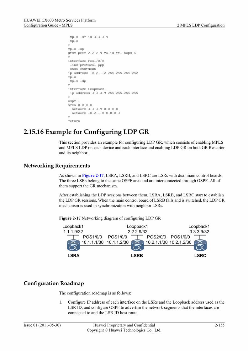
mpls lsr-id 3.3.3.9 mpls#mpls ldpgtsm peer 2.2.2.9 valid-ttl-hops 6#interface Pos1/0/0 link-protocol ppp undo shutdownip address 10.2.1.2 255.255.255.252mpls mpls ldp#interface LoopBack1 ip address 3.3.3.9 255.255.255.255#ospf 1area 0.0.0.0 network 3.3.3.9 0.0.0.0 network 10.2.1.0 0.0.0.3#return
2.15.16 Example for Configuring LDP GRThis section provides an example for configuring LDP GR, which consists of enabling MPLSand MPLS LDP on each device and each interface and enabling LDP GR on both GR Restarterand its neighbor.
Networking Requirements
As shown in Figure 2-17, LSRA, LSRB, and LSRC are LSRs with dual main control boards.The three LSRs belong to the same OSPF area and are interconnected through OSPF. All ofthem support the GR mechanism.
After establishing the LDP sessions between them, LSRA, LSRB, and LSRC start to establishthe LDP GR sessions. When the main control board of LSRB fails and is switched, the LDP GRmechanism is used in synchronization with neighbor LSRs.
Figure 2-17 Networking diagram of configuring LDP GR
LSRB
POS1/0/010.1.1.1/30
POS1/0/010.1.1.2/30
LSRA LSRC
POS2/0/010.2.1.1/30
POS1/0/010.2.1.2/30
Loopback11.1.1.9/32
Loopback12.2.2.9/32
Loopback13.3.3.9/32
Configuration Roadmap
The configuration roadmap is as follows:
1. Configure IP address of each interface on the LSRs and the Loopback address used as theLSR ID, and configure OSPF to advertise the network segments that the interfaces areconnected to and the LSR ID host route.
HUAWEI CX600 Metro Services PlatformConfiguration Guide - MPLS 2 MPLS LDP Configuration
Issue 01 (2011-05-30) Huawei Proprietary and ConfidentialCopyright © Huawei Technologies Co., Ltd.
2-155
2. Configure the OSPF GR function on each LSR.3. Enable MPLS and MPLS LDP on each LSR globally.4. Enable MPLS and MPLS LDP on each interface.5. Configure parameters during LDP session negotiation on LSRB.6. Enable the GR function of MPLS LDP on each LSR.7. Configure the GR session of MPLS LDP and neighboring parameters on LSRB.
Data PreparationTo complete the configuration, you need the following data:
l IP address of each interface, OSPF process ID, and OSPF area IDl OSPF GR intervall Time of the LDP Reconnect timer (300 seconds by default)l Time of the LDP Neighbor-liveness timer (600 seconds by default)l Time of the LDP Recovery timer (300 seconds by default)
Procedure
Step 1 Configure the IP address for each interface. The configuration details are not mentioned here.
Step 2 Configure OSPF to advertise the network segments that the interfaces are connected to and theLSR ID host route. The configuration details are not mentioned here.
Step 3 Configure the OSPF GR function.
# Configure LSRA.
<LSRA> system-view[LSRA] ospf 1[LSRA-ospf-1] opaque-capability enable[LSRA-ospf-1] graceful-restart[LSRA-ospf-1] quit
# Configure LSRB.
<LSRB> system-view[LSRB] ospf 1[LSRB-ospf-1] opaque-capability enable[LSRB-ospf-1] graceful-restart[LSRB-ospf-1] quit
# Configure LSRC.
<LSRC> system-view[LSRC] ospf 1[LSRC-ospf-1] opaque-capability enable[LSRC-ospf-1] graceful-restart[LSRC-ospf-1] quit
Step 4 Configure the MPLS and MPLS LDP functions on each node globally.
# Configure LSRA.
[LSRA] mpls lsr-id 1.1.1.9[LSRA] mpls[LSRA-mpls] quit[LSRA] mpls ldp[LSRA-mpls-ldp] quit
2 MPLS LDP ConfigurationHUAWEI CX600 Metro Services Platform
Configuration Guide - MPLS
2-156 Huawei Proprietary and ConfidentialCopyright © Huawei Technologies Co., Ltd.
Issue 01 (2011-05-30)
# Configure LSRB.
[LSRB] mpls lsr-id 2.2.2.9[LSRB] mpls[LSRB-mpls] quit[LSRB] mpls ldp[LSRB-mpls-ldp] quit
# Configure LSRC.
[LSRC] mpls lsr-id 3.3.3.9[LSRC] mpls[LSRC-mpls] quit[LSRC] mpls ldp[LSRC-mpls-ldp] quit
Step 5 Configure the MPLS and MPLS LDP functions on each interface.
# Configure LSRA.
[LSRA] interface pos 1/0/0[LSRA-Pos1/0/0] mpls[LSRA-Pos1/0/0] mpls ldp[LSRA-Pos1/0/0] quit
# Configure LSRB.
[LSRB] interface pos 1/0/0[LSRB-Pos1/0/0] mpls[LSRB-Pos1/0/0] mpls ldp[LSRB-Pos1/0/0] quit[LSRB] interface pos 2/0/0[LSRB-Pos2/0/0] mpls[LSRB-Pos2/0/0] mpls ldp[LSRB-Pos2/0/0] quit
# Configure LSRC.
[LSRC] interface pos 1/0/0[LSRC-Pos1/0/0] mpls[LSRC-Pos1/0/0] mpls ldp[LSRC-Pos1/0/0] quit
After the preceding configuration is complete, the local LDP sessions are established betweenLSRA and LSRB, and between LSRB and LSRC.
Run the display mpls ldp session command on each LSR, and you can view the establishedLDP session.
Take the display on LSRA as an example.
[LSRA] display mpls ldp session LDP Session(s) in Public Network Codes: LAM(Label Advertisement Mode), SsnAge Unit(DDDD:HH:MM) A '*' before a session means the session is being deleted. ------------------------------------------------------------------------------ PeerID Status LAM SsnRole SsnAge KASent/Rcv ------------------------------------------------------------------------------ 2.2.2.9:0 Operational DU Passive 0000:00:02 9/9 ------------------------------------------------------------------------------ TOTAL: 1 session(s) Found.
Step 6 Configure the LDP GR function.
# Configure LSRA.
[LSRA] mpls ldp[LSRA-mpls-ldp] graceful-restartWarning: All the related sessions will be deleted if the operation is performed
HUAWEI CX600 Metro Services PlatformConfiguration Guide - MPLS 2 MPLS LDP Configuration
Issue 01 (2011-05-30) Huawei Proprietary and ConfidentialCopyright © Huawei Technologies Co., Ltd.
2-157
!Continue? (y/n)y[LSRA-mpls-ldp] quit
# Configure LSRB.
[LSRB] mpls ldp[LSRB-mpls-ldp] graceful-restartWarning: All the related sessions will be deleted if the operation is performed!Continue? (y/n)y[LSRB-mpls-ldp] quit
# Configure LSRC.
[LSRC] mpls ldp[LSRC-mpls-ldp] graceful-restartWarning: All the related sessions will be deleted if the operation is performed!Continue? (y/n)y[LSRC-mpls-ldp] quit
Step 7 Configure the parameters of LDP GR on the GR Restarter.
# Configure LSRB.
[LSRB] mpls ldp[LSRB-mpls-ldp] graceful-restart timer reconnect 300Warning: All the related sessions will be deleted if the operation is performed!Continue? (y/n)y[LSRB-mpls-ldp] graceful-restart timer neighbor-liveness 600Warning: All the related sessions will be deleted if the operation is performed!Continue? (y/n)y[LSRB-mpls-ldp] graceful-restart timer recovery 300Warning: All the related sessions will be deleted if the operation is performed!Continue? (y/n)y[LSRB-mpls-ldp] quit
Step 8 Verify the configuration.
# After the configuration, run the display mpls ldp session verbose command on the LSR, andyou can view that On is displayed in the Session FT Flag field.
Take the display on LSRA as an example.
[LSRA]display mpls ldp session verbose LDP Session(s) in Public Network ------------------------------------------------------------------------------ Peer LDP ID : 2.2.2.9:0 Local LDP ID : 1.1.1.9:0 TCP Connection : 1.1.1.9 <- 2.2.2.9 Session State : Operational Session Role : Passive Session FT Flag : On MD5 Flag : Off Reconnect Timer : 300 Sec Recovery Timer : 300 Sec Keychain Name : ---
Negotiated Keepalive Hold Timer : 45 Sec Configured Keepalive Send Timer : 3 Sec Keepalive Message Sent/Rcvd : 1/1 (Message Count) Label Advertisement Mode : Downstream Unsolicited Label Resource Status(Peer/Local) : Available/Available Session Age : 0000:00:00 (DDDD:HH:MM) Session Deletion Status : No
Capability: Capability-Announcement : Off
Outbound&Inbound Policies applied : NULL
Addresses received from peer: (Count: 3) 10.1.1.2 10.2.1.1 2.2.2.9
------------------------------------------------------------------------------
2 MPLS LDP ConfigurationHUAWEI CX600 Metro Services Platform
Configuration Guide - MPLS
2-158 Huawei Proprietary and ConfidentialCopyright © Huawei Technologies Co., Ltd.
Issue 01 (2011-05-30)
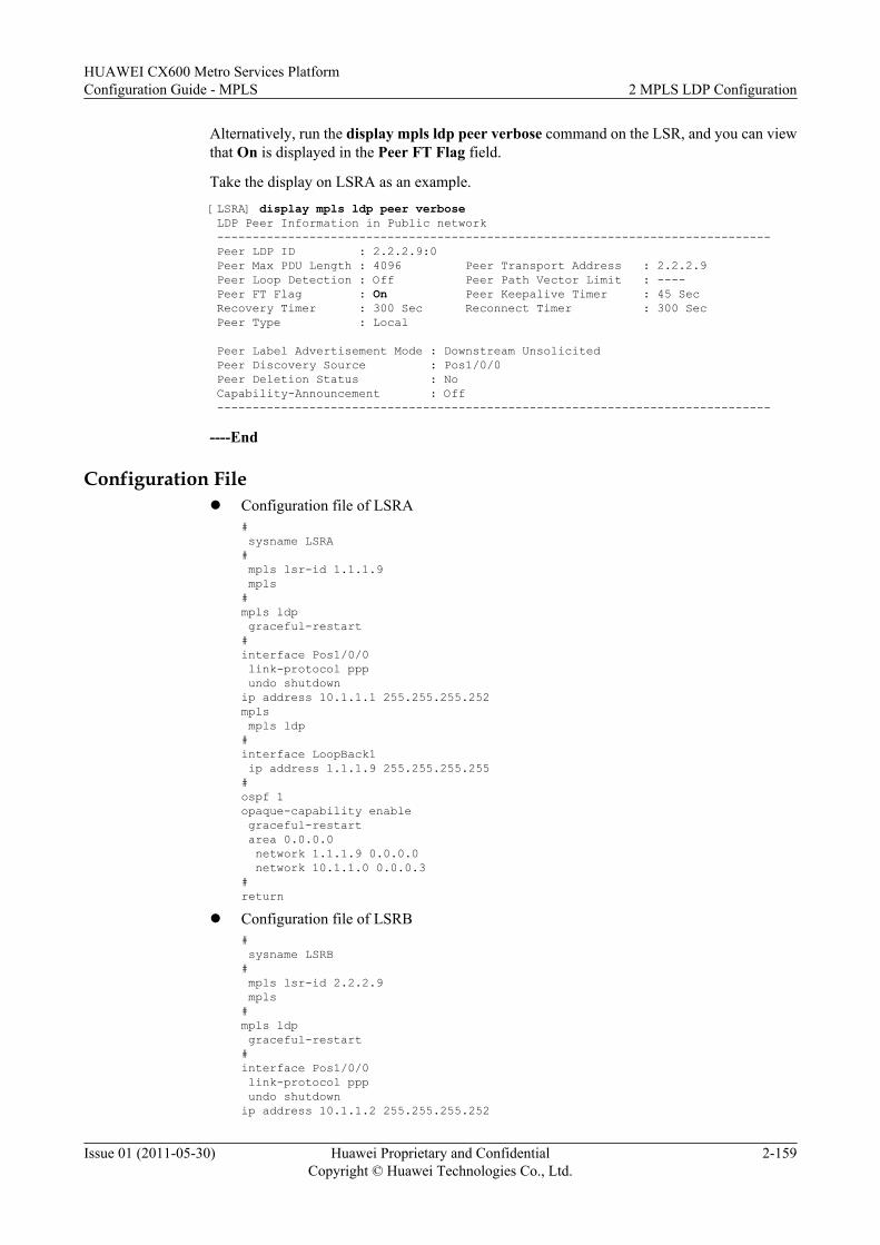
Alternatively, run the display mpls ldp peer verbose command on the LSR, and you can viewthat On is displayed in the Peer FT Flag field.
Take the display on LSRA as an example.[LSRA] display mpls ldp peer verbose LDP Peer Information in Public network ------------------------------------------------------------------------------ Peer LDP ID : 2.2.2.9:0 Peer Max PDU Length : 4096 Peer Transport Address : 2.2.2.9 Peer Loop Detection : Off Peer Path Vector Limit : ---- Peer FT Flag : On Peer Keepalive Timer : 45 Sec Recovery Timer : 300 Sec Reconnect Timer : 300 Sec Peer Type : Local
Peer Label Advertisement Mode : Downstream Unsolicited Peer Discovery Source : Pos1/0/0 Peer Deletion Status : No Capability-Announcement : Off ------------------------------------------------------------------------------
----End
Configuration Filel Configuration file of LSRA
# sysname LSRA# mpls lsr-id 1.1.1.9 mpls#mpls ldp graceful-restart#interface Pos1/0/0 link-protocol ppp undo shutdownip address 10.1.1.1 255.255.255.252mpls mpls ldp#interface LoopBack1 ip address 1.1.1.9 255.255.255.255#ospf 1opaque-capability enable graceful-restart area 0.0.0.0 network 1.1.1.9 0.0.0.0 network 10.1.1.0 0.0.0.3#return
l Configuration file of LSRB# sysname LSRB# mpls lsr-id 2.2.2.9 mpls#mpls ldp graceful-restart#interface Pos1/0/0 link-protocol ppp undo shutdownip address 10.1.1.2 255.255.255.252
HUAWEI CX600 Metro Services PlatformConfiguration Guide - MPLS 2 MPLS LDP Configuration
Issue 01 (2011-05-30) Huawei Proprietary and ConfidentialCopyright © Huawei Technologies Co., Ltd.
2-159
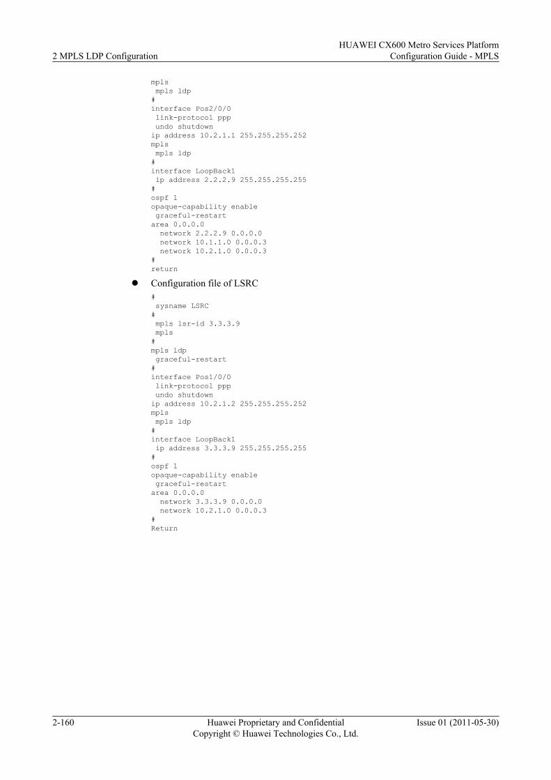
mpls mpls ldp#interface Pos2/0/0 link-protocol ppp undo shutdownip address 10.2.1.1 255.255.255.252mpls mpls ldp#interface LoopBack1 ip address 2.2.2.9 255.255.255.255#ospf 1opaque-capability enable graceful-restartarea 0.0.0.0 network 2.2.2.9 0.0.0.0 network 10.1.1.0 0.0.0.3 network 10.2.1.0 0.0.0.3#return
l Configuration file of LSRC# sysname LSRC# mpls lsr-id 3.3.3.9 mpls#mpls ldp graceful-restart#interface Pos1/0/0 link-protocol ppp undo shutdownip address 10.2.1.2 255.255.255.252mpls mpls ldp#interface LoopBack1 ip address 3.3.3.9 255.255.255.255#ospf 1opaque-capability enable graceful-restartarea 0.0.0.0 network 3.3.3.9 0.0.0.0 network 10.2.1.0 0.0.0.3#Return
2 MPLS LDP ConfigurationHUAWEI CX600 Metro Services Platform
Configuration Guide - MPLS
2-160 Huawei Proprietary and ConfidentialCopyright © Huawei Technologies Co., Ltd.
Issue 01 (2011-05-30)
3 MPLS TE Configuration
About This Chapter
MPLS TE tunnels transmit MPLS L2VPN (VLL and VPLS) services and MPLS L3VPN servicesand thus provide high security and guarantees reliable QoS for VPN services.
3.1 Introduction to MPLS TEIntegrating the Multiprotocol Label Switching (MPLS) technology with the Traffic Engineering(TE) technology, MPLS TE addresses the problem of the congestion caused by load imbalance.
3.2 Configuring Static CR-LSPThe configuration of a static CR-LSP is simple and label allocation is performed manually, ratherthan by using a signaling protocol to exchange control packets. This consumes a few resources.
3.3 Configuring a Static Bidirectional Co-routed LSPA static bidirectional co-routed label switched path (LSP) is composed of two static constraint-based routed (CR) LSPs in opposite directions. Multiprotocol Label Switching (MPLS) TrafficEngineering (TE) supports MPLS forwarding in both directions along such an LSP.
3.4 Configuring an RSVP-TE TunnelAn RSVP-TE tunnel is the prerequisite for the configuration of TE attributes.
3.5 Referencing the CR-LSP Attribute Template to Set Up a CR-LSPBy configuring a CR-LSP attribute template to set up CR-LSPs, you can simply theconfigurations and make the configurations of CR-LSPs more flexible.
3.6 Adjusting RSVP Signaling ParametersRSVP-TE provides various parameters, which meet the requirements for reliability, networkresources, and advanced MPLS features.
3.7 Configuring RSVP AuthenticationRSVP authentication prevents unauthorized nodes from setting up RSVP neighbor relationshipswith the local node and prevents spoofing of forged packets.
3.8 Adjusting the Path of CR-LSPYou can adjust and configure the method of calculating CR-LSPs.
3.9 Adjusting the Establishment of MPLS TE TunnelsBy configuring multiple attributes of an MPLS TE tunnel, you can adjust the parameters duringthe establishment of the MPLS TE tunnel.
HUAWEI CX600 Metro Services PlatformConfiguration Guide - MPLS 3 MPLS TE Configuration
Issue 01 (2011-05-30) Huawei Proprietary and ConfidentialCopyright © Huawei Technologies Co., Ltd.
3-1
3.10 Adjusting the Traffic Forwarding of an MPLS TE TunnelBy adjusting the forwarding of MPLS TE traffic, you can modify the path along which IP trafficor MPLS traffic is transmitted, or limit the types of traffic that can be transmitted along a TEtunnel.
3.11 Adjusting Flooding Threshold of Bandwidth ChangeBy adjusting the flooding threshold of the bandwidth change, you can suppress the frequencyof TEDB update and flooding, which minimizes network resource consumption.
3.12 Configuring Automatic Adjustment of the Tunnel BandwidthBy being enabled with the automatic bandwidth adjustment, the system can adjust the bandwidthof a tunnel automatically according to the actual traffic volume.
3.13 Configuring the Limit Rate of MPLS TE TrafficTo limit TE tunnel traffic within the bandwidth range that is actually configured, you need toset a rate limit for the TE tunnel traffic.
3.14 Configuring DS-TE TunnelBy integrating traditional TE tunnels with DiffServ models, DS-TE can provide QoS accordingto specific service types.
3.15 Configuring MPLS TE FRRMPLS TE FRR is a local protection technique and is used to protect a CR-LSP against link faultsand node faults. MPLS TE FRR needs to be configured manually.
3.16 Configuring MPLS TE Auto FRRMPLS TE Auto FRR is a local protection technique and is used to protect a CR-LSP against linkfaults and node faults. MPLS TE Auto FRR does not need to be configured manually.
3.17 Configuring CR-LSP BackupBy configuring CR-LSP backup, you can provide end-to-end protection for a CR-LSP.
3.18 Configuring Synchronization of the Bypass Tunnel and the Backup CR-LSPThis section describes that after the primary CR-LSP is faulty, the system starts the TE FRRbypass tunnel and tries to restore the primary CR-LSP the same time it sets up a backup CR-LSP.
3.19 Configuring RSVP GRThis section describes how to configure RSVP-TE GR so that devices along an RSVP-TE tunnelcan retain RSVP sessions during a master/slave switchover.
3.20 Configuring Static BFD for CR-LSPThis section describes how to configure a static BFD session to detect link faults in static CR-LSPs or RSVP CR-LSPs.
3.21 Configuring Static BFD for TEThis section describes how to configure a static BFD session to detect faults in a TE tunnel.
3.22 Configuring Dynamic BFD for CR-LSPThis section describes how to configure a dynamic BFD session to detect link faults in a staticCR-LSP or an RSVP CR-LSP.
3.23 Configuring Dynamic BFD for RSVPThis section describes how to configure a dynamic BFD session to detect faults in links betweenRSVP neighbors.
3.24 Configuring LDP over TEThis section describes how to configure LDP over TE.
3 MPLS TE ConfigurationHUAWEI CX600 Metro Services Platform
Configuration Guide - MPLS
3-2 Huawei Proprietary and ConfidentialCopyright © Huawei Technologies Co., Ltd.
Issue 01 (2011-05-30)
3.25 Maintaining MPLS TEThis section describes how to clear operation information about MPLS TE, and reset theautomatic bandwidth adjustment.
3.26 Configuration ExamplesThe following sections provide several examples for configuring MPLS TE.Each configurationexample consists of the networking requirements, configuration precautions, configurationroadmap, configuration procedures, and configuration files.
HUAWEI CX600 Metro Services PlatformConfiguration Guide - MPLS 3 MPLS TE Configuration
Issue 01 (2011-05-30) Huawei Proprietary and ConfidentialCopyright © Huawei Technologies Co., Ltd.
3-3
3.1 Introduction to MPLS TEIntegrating the Multiprotocol Label Switching (MPLS) technology with the Traffic Engineering(TE) technology, MPLS TE addresses the problem of the congestion caused by load imbalance.
3.1.1 MPLS TE OverviewMPLS TE reserves resources for tunnels to be set up, allowing traffic to be load-balanced amongnodes without passing through congested nodes.
3.1.2 MPLS TE Features Supported by the CX600MPLS TE features supported by the system include RSVP-TE tunnels, MPLS TE reliability,MPLS TE QoS, and MPLS TE security.
3.1.1 MPLS TE OverviewMPLS TE reserves resources for tunnels to be set up, allowing traffic to be load-balanced amongnodes without passing through congested nodes.
TENetwork resource insufficiency and load imbalance result in congestion on a network, affectingthe performance of a backbone network. TE prevents network congestion and optimizes thenetwork resources.
TE dynamically monitors traffic and load on network elements and adjusts parameters relevantto traffic control, routing, and resource constraints in real time. This optimizes utilization ofnetwork resources and prevents imbalance-triggered congestion.
MPLS TEAs a combination of MPLS and TE, MPLS TE load-balances traffic on a network by setting upan LSP over a specified path to reserve resources for traffic that will not pass through congestednodes.
An LSP with a higher priority preempts bandwidth resources of LSPs with lower priorities,providing sufficient bandwidth for services on the LSP with a higher priority in the case ofbandwidth insufficiency.
If a link fault or a node fault occurs, MPLS TE uses path backup and fast reroute (FRR) to ensureuninterrupted traffic.
Administrators use MPLS TE to create LSPs to eliminate network congestions and use specialoffline utility to analyze traffic if the number of LSPs increases to a certain extent.
3.1.2 MPLS TE Features Supported by the CX600MPLS TE features supported by the system include RSVP-TE tunnels, MPLS TE reliability,MPLS TE QoS, and MPLS TE security.
NOTEThis section describes MPLS TE features that are supported by the CX600. For details about MPLS TEfeatures, see the section "MPLS TE" in the HUAWEI CX600 Metro Services Platform Feature Description- MPLS.
3 MPLS TE ConfigurationHUAWEI CX600 Metro Services Platform
Configuration Guide - MPLS
3-4 Huawei Proprietary and ConfidentialCopyright © Huawei Technologies Co., Ltd.
Issue 01 (2011-05-30)
Static MPLS TE TunnelA static MPLS TE tunnel allows labels to be allocated manually, without signaling protocolsexchanging control packets. Static MPLS TE tunnels are established on devices of lowperformance on a stable network.
Static MPLS TE tunnels have the highest priority among tunnels and therefore their bandwidthis not preemptive. In addition, static MPLS TE tunnels do not preempt bandwidth of other typesof CR-LSPs.
RSVP-TE TunnelRSVP-TE tunnels are set up by the RSVP-TE signaling protocol and change dynamicallyaccording to the network topology.
RSVP-TE features supported by the CX600 are as follows:
l Collecting and advertising link informationRSVP-TE uses an extended IGP (OSPF-TE or ISIS-TE) to collect and advertise TE linkinformation and creates a traffic engineering database (TEDB). An extended IGP floodsthe link information periodically. If a link goes Up or Down, link attributes change, or thereservable bandwidth on the link changes to a certain extent, the extended IGP floods thelink information. The flood threshold is adjusted by using command lines.
l Path calculationOn the CX600, the path of a TE tunnel is calculated by using CSPF. When multiple pathsshare the same weights, one path is selected by using the configured tie-breaking.In addition to the reservable bandwidth and management group attributes, the followingattributes are configurable:– Tunnel bandwidth– Affinity attribute– Explicit path– Maximum hop limit– Shared Risk Link Group (SRLG)
l Establishment of an RSVP-TE tunnelIf configured, the system records routes and labels, or detects loops during the establishmentof an RSVP-TE tunnel. When the resources are insufficient, preemption is triggered basedon the setup and the holding priorities.If an RSVP-TE tunnel fails to be established, the system re-establishes the RSVP-TE tunnelperiodically.
l Signaling mechanismRSVP-TE reserves resources in either fixed filter (FF) or shared-explicit (SE) mode. Thefollowing extended RSVP mechanisms are supported by the CX600 to relieve networkburden and improve reliability:– Confirmation and retransmission for RSVP messages– Summary refreshing– Hello mechanismIn addition, RSVP authentication is supported by the CX600 to improve network security.
l Traffic forwarding
HUAWEI CX600 Metro Services PlatformConfiguration Guide - MPLS 3 MPLS TE Configuration
Issue 01 (2011-05-30) Huawei Proprietary and ConfidentialCopyright © Huawei Technologies Co., Ltd.
3-5
VPN traffic is directed to TE tunnels by using configured policy-based routes. Non-VPNtraffic is directed to TE tunnels by using static routes, policy-based routes, IGP shortcut,or forwarding adjacency.
l Tunnel optimization and adjustmentAfter tunnels are set up, the tunnels are adjusted and optimized by using the followingfeatures:– Tunnel re-optimization: A path of a CR-LSP is calculated periodically. If a better path
is discovered, a new CR-LSP is established over a better path, and traffic switches tothe new CR-LSP.
– Route pinning: The path of an established tunnel is pinned, which means that the pathof the tunnel is not optimized if a better path is discovered.
ReliabilityThe CX600 supports the following reliability features applied to MPLS TE tunnels:
l FRRFRR is a local protection mechanism in RSVP-TE. FRR protects traffic on CR-LSP linksand nodes if faults occur. FRR is classified into manual FRR and automatic FRR.
l CR-LSP backupCR-LSP backup protects traffic on an entire RSVP-TE CR-LSP from end to end. If aprimary CR-LSP fails, the system establishes a backup CR-LSP; if the backup CR-LSPfails, the system attempts to establish a best-effort path.
l BFDBFD detects a fault in a CR-LSP at millisecond level. BFD allows rapid detection,requirements for which hardware detection does not satisfy.
l RSVP GRRSVP GR is a status recovery mechanism for RSVP-TE tunnels. If a switchover on thecontrol plane triggered by a fault or an operation, RSVP GR helps the system to properlyforwarding data on the forwarding plane and restore the RSVP-TE LSP on the control plane.FRR is supported by the CX600 during the GR process.
l MPLS tunnel protection groupAn MPLS tunnel protection group provides an end-to-end mechanism applicable to MPLSTE tunnels, including but not limited to RSVP-TE tunnels. In an MPLS tunnel protectiongroup, one tunnel protects traffic on other tunnels.
NOTEFor configurations of an MPLS tunnel protection group, see the section "MPLS OAM."
l NSRIf a software or hardware fault occurs on the control plane, NSR ensures the uninterruptedforwarding and the uninterrupted connection of the control plane. In addition, the controlplane of a neighbor does not sense the fault.
DS-TEDS-TE maps different service types of traffic (such as voice, video, or data traffic) to LSPs. Thepath through which traffic passes is consistent with traffic engineering constraints of a specificservice type.
DS-TE supports either non-IETF or IETF mode on the CX600.
3 MPLS TE ConfigurationHUAWEI CX600 Metro Services Platform
Configuration Guide - MPLS
3-6 Huawei Proprietary and ConfidentialCopyright © Huawei Technologies Co., Ltd.
Issue 01 (2011-05-30)
l The non-IETF (non-standard) mode supports combinations between two CTs (CT0 andCT1) and eight priorities (0 to 7) and the Bandwidth Constraints models (RDM and MAM).
Class-Type (CT) refers to the class mapped to a service. The priority refers to the LSPpreemption priority.
l The IEFT (standard) mode supports combinations between eight CTs (CT0 to CT7) andeight priorities (0 to 7). In addition, it supports the following Bandwidth Constraintsmodels: RDM, MAM, and extended-MAM.
A DS-TE tunnel supports TE FRR, hot standby, protection group, and CT traffic statistics.
3.2 Configuring Static CR-LSPThe configuration of a static CR-LSP is simple and label allocation is performed manually, ratherthan by using a signaling protocol to exchange control packets. This consumes a few resources.
3.2.1 Establishing the Configuration TaskBefore configuring a static CR-LSP, familiarize yourself with the applicable environment,complete the pre-configuration tasks, and obtain the required data. This can help you rapidlyand correctly finish the configuration task.
3.2.2 Enabling MPLS TEBefore setting up a static CR-LSP, you must enable MPLS TE.
3.2.3 (Optional) Configuring Link BandwidthBy configuring the link bandwidth, you can set the bandwidth of a CR-LSP.
3.2.4 Configuring the MPLS TE Tunnel InterfaceBefore setting up an MPLS TE tunnel, you must create a tunnel interface.
3.2.5 Configuring the Ingress of the Static CR-LSPTo set up a static CR-LSP, you need to specify the ingress node of the CR-LSP.
3.2.6 Configuring the Transit of the Static CR-LSPTo set up a static CR-LSP, you need to specify the transit nodes of the CR-LSP. This procedureis optional because the CR-LSP can have no transit node.
3.2.7 Configuring the Egress of the Static CR-LSPTo set up a static CR-LSP, you need to specify the egress node of the CR-LSP.
3.2.8 Checking the ConfigurationAfter the configuration of a static CR-LSP, you can view the static CR-LSP status.
3.2.1 Establishing the Configuration TaskBefore configuring a static CR-LSP, familiarize yourself with the applicable environment,complete the pre-configuration tasks, and obtain the required data. This can help you rapidlyand correctly finish the configuration task.
Applicable Environment
The configuration of a static CR-LSP is a simple process. Labels are manually allocated and thesignaling protocol does not need to exchange control packets. The setup of a static CR-LSPconsumes a few resources. In addition, you need to configure neither the IGP TE nor CSPF forthe static CR-LSP.
HUAWEI CX600 Metro Services PlatformConfiguration Guide - MPLS 3 MPLS TE Configuration
Issue 01 (2011-05-30) Huawei Proprietary and ConfidentialCopyright © Huawei Technologies Co., Ltd.
3-7
The static CR-LSP cannot dynamically adapt to a changing network. Therefore, its applicationis very limited.
The static CR-LSP is a special static LSP that has the same setup constraints and uses the samelabel space ranging from 16 to 1023.
Pre-configuration TasksBefore configuring a static CR-LSP, complete the following tasks:
l Configuring the static route or IGP to ensure the reachability between LSRsl Configuring an MPLS LSR ID on each LSRl Enabling basic MPLS functions on each LSR globally and on each interface
Data PreparationTo configure a static CR-LSP, you need the following data.
No. Data
1 Physical links through which a static CR-LSP passes
2 Nodes through which the static CR-LSP passes
3 Values for outgoing labels on LSRs along the static CR-LSP
4 Number, tunnel ID, and destination address of the tunnel interface
5 Destination address of the static CR-LSP
6 Next hop address or outgoing interface on the ingress
7 Incoming interface, next hop address, or outgoing interface on each transit
8 Incoming interface on the egress
9 Bandwidth of the ingress and the transit node(s)
NOTE
l The value of the outgoing label on each node is the value of the incoming label of its next node.
l The destination address of a static CR-LSP is the destination address of the TE tunnel interface.
3.2.2 Enabling MPLS TEBefore setting up a static CR-LSP, you must enable MPLS TE.
ContextDo as follows on each node along the static CR-LSP:
Procedure
Step 1 Run:
3 MPLS TE ConfigurationHUAWEI CX600 Metro Services Platform
Configuration Guide - MPLS
3-8 Huawei Proprietary and ConfidentialCopyright © Huawei Technologies Co., Ltd.
Issue 01 (2011-05-30)
system-view
The system view is displayed.
Step 2 Run:mpls
The MPLS view is displayed.
Step 3 Run:mpls te
MPLS TE is enabled on the node globally.
To enable MPLS TE on each interface, enable MPLS TE globally in the MPLS view first.
Step 4 Run:quit
Return to the system view.
Step 5 Run:interface interface-type interface-number
The view of the interface is displayed.
Step 6 Run:mpls
The MPLS is enabled on the interface.
Step 7 Run:mpls te
The MPLS TE is enabled on the interface.
NOTE
When the MPLS TE is disabled in the interface view, all the CR-LSPs on the current interface change toDown.
When the MPLS TE is disabled in the MPLS view, the MPLS TE on each interface is disabled, and allCR-LSPs are deleted.
----End
3.2.3 (Optional) Configuring Link BandwidthBy configuring the link bandwidth, you can set the bandwidth of a CR-LSP.
ContextNOTE
To constrain the bandwidth of CR-LSPs, the procedure is mandatory. In addition, the mpls te lsp-tpoutbound command must be run on the corresponding tunnel interface.
By default, the maximum reservable bandwidth on the link is 0 bit/s. If the maximum reservable bandwidthis not configured, when the bandwidth of the CR-LSP is constrained, the bandwidth of the CR-LSP is morethan the maximum reservable bandwidth. Therefore, the CR-LSP cannot be set up.
Do as follows on each node along the CR-LSP:
HUAWEI CX600 Metro Services PlatformConfiguration Guide - MPLS 3 MPLS TE Configuration
Issue 01 (2011-05-30) Huawei Proprietary and ConfidentialCopyright © Huawei Technologies Co., Ltd.
3-9
Procedure
Step 1 Run:system-view
The system view is displayed.
Step 2 Run:interface interface-type interface-number
The MPLS-TE-enabled interface view is displayed.
Step 3 Run:mpls te bandwidth max-reservable-bandwidth bw-value
The maximum available bandwidth of the link is configured.
Step 4 Run:mpls te bandwidth { bc0 bc0-bw-value | bc1 bc1-bw-value }*
The BC bandwidth of the link is configured.
NOTE
l The maximum reservable bandwidth of a link cannot be greater than the actual bandwidth of the link.A maximum of 80% of the actual bandwidth of the link is recommended for the maximum reservablebandwidth of the link.
l Neither the BC0 bandwidth nor the BC1 bandwidth can be greater than the maximum reservablebandwidth of the link.
l If an MPLS TE tunnel to be set up requires the bandwidth that is larger than 67105 kbit/s, it isrecommended that the reserved bandwidth be one thousandth more that the bandwidth to be configured.
----End
3.2.4 Configuring the MPLS TE Tunnel InterfaceBefore setting up an MPLS TE tunnel, you must create a tunnel interface.
ContextDo as follows on the ingress node of a static CR-LSP:
Procedure
Step 1 Run:system-view
The system view is displayed.
Step 2 Run:interface tunnel tunnel-number
The tunnel interface is created and the tunnel interface view is displayed.
Step 3 To configure the IP address of the tunnel interface, select one of the following commands.l Run:
ip address ip-address { mask | mask-length } [ sub ]The IP address of the tunnel interface is configured.
3 MPLS TE ConfigurationHUAWEI CX600 Metro Services Platform
Configuration Guide - MPLS
3-10 Huawei Proprietary and ConfidentialCopyright © Huawei Technologies Co., Ltd.
Issue 01 (2011-05-30)
The secondary IP address of the tunnel interface can be configured only after the primary IPaddress is configured.
l Or, run:ip address unnumbered interface interface-type interface-numberThe tunnel interface is configured to borrow an IP address from other interfaces.
To forward traffic, the tunnel interface must have an IP address; however, because the MPLSTE tunnel is unidirectional, no peer address is needed. Therefore, it is unnecessary to configurethe IP address separately for the tunnel interface. The tunnel interface often borrows an LSR IDof the ingress node as the address.
NOTE
Because the type of the packet forwarded by the MPLS TE tunnel is MPLS, the commands, such as ipurpf commands, related to IP packet forwarding configured on this interface are invalid.
Step 4 Run:tunnel-protocol mpls te
MPLS TE is configured to be the tunnel protocol.
Step 5 Run:destination ip-address
The destination address of the tunnel is configured, which is usually the LSR ID of the egressnode.
Different types of tunnels need different destination addresses. When the tunnel protocol ischanged to MPLS TE from other different protocols, the configured destination is deletedautomatically and needs to be reconfigured.
Step 6 Run:mpls te tunnel-id tunnel-id
The tunnel ID is configured.
Step 7 Run:mpls te signal-protocol cr-static
The signal protocol of the tunnel is configured to be CR-static.
Step 8 (Optional) Run:mpls te signalled tunnel-name
The tunnel name is specified.
Step 9 Run:mpls te commit
The current tunnel configuration is committed.
NOTE
If MPLS TE parameters on a tunnel interface are modified, you need to run the mpls te commit commandto activate them.
----End
3.2.5 Configuring the Ingress of the Static CR-LSPTo set up a static CR-LSP, you need to specify the ingress node of the CR-LSP.
HUAWEI CX600 Metro Services PlatformConfiguration Guide - MPLS 3 MPLS TE Configuration
Issue 01 (2011-05-30) Huawei Proprietary and ConfidentialCopyright © Huawei Technologies Co., Ltd.
3-11
ContextDo as follows on the ingress of a static CR-LSP:
Procedure
Step 1 Run:system-view
The system view is displayed.
Step 2 Run:static-cr-lsp ingress { tunnel-interface tunnel interface-number | tunnel-name } destination destination-address { nexthop next-hop-address | outgoing-interface interface-type interface-number } out-label out-label [ bandwidth [ ct0 | ct1 ] bandwidth ]
The LSR is set as the ingress of the specified static CR-LSP.
tunnel-number specifies the MPLS TE tunnel interface that uses this static CR-LSP. By default,the Bandwidth Constraints value is ct0, and the value of bandwidth is 0. The bandwidth usedby the tunnel cannot be higher than the maximum reservable bandwidth of the link.
The value of tunnel-name cannot be spaces or abbreviations. For example, if a tunnel interfacenamed Tunnel 2/0/0 is specified in the interface tunnel 2/0/0 command, tunnel-name specifiedin the static-cr-lsp ingress command must be Tunnel2/0/0 or tunnel2/0/0; otherwise, the tunnelcannot be set up. For the transit and egress, tunnel name consistency is not required.
The next hop or outgoing interface is determined by the route from the ingress to the egress. Forthe difference between the next hop and outgoing interface, refer to "Static Route Configuration"in the HUAWEI CX600 Metro Services Platform Configuration Guide - IP Routing.
----End
3.2.6 Configuring the Transit of the Static CR-LSPTo set up a static CR-LSP, you need to specify the transit nodes of the CR-LSP. This procedureis optional because the CR-LSP can have no transit node.
ContextIf the static CR-LSP has only the ingress and egress, this configuration is not needed. If the staticCR-LSP has one or more transits, do as follows on the transit node:
Procedure
Step 1 Run:system-view
The system view is displayed.
Step 2 Run:static-cr-lsp transit lsp-name incoming-interface interface-type interface-number in-label in-label-value { nexthop next-hop-address | outgoing-interface interface-type interface-number } out-label out-label-value [ bandwidth [ ct0 | ct1 ] bandwidth ]
3 MPLS TE ConfigurationHUAWEI CX600 Metro Services Platform
Configuration Guide - MPLS
3-12 Huawei Proprietary and ConfidentialCopyright © Huawei Technologies Co., Ltd.
Issue 01 (2011-05-30)
The LSR is set as the transit node of the specified static CR-LSP.
No restriction is specified for the tunnel-name of the transit and the egress, but the tunnel-name should not be a duplicate of the existing tunnel name on the node.
----End
3.2.7 Configuring the Egress of the Static CR-LSPTo set up a static CR-LSP, you need to specify the egress node of the CR-LSP.
Context
Do as follows on the egress of the static CR-LSP:
Procedure
Step 1 Run:system-view
The system view is displayed.
Step 2 Run:static-cr-lsp egress lsp-name incoming-interface interface-type interface-number in-label in-label [ lsrid ingress-lsr-id tunnel-id tunnel-id ]
The LSR is configured as the egress of the specified static CR-LSP.
----End
3.2.8 Checking the ConfigurationAfter the configuration of a static CR-LSP, you can view the static CR-LSP status.
PrerequisiteThe configurations of the static MPLS TE tunnel function are complete.
Procedurel Run the display mpls static-cr-lsp [ lsp-name ] [ { include | exclude } ip-address mask-
length ] [ verbose ] command to check information about the static CR-LSP.
l Run the display mpls te tunnel [ destination ip-address ] [ lsp-id ingress-lsr-id session-id local-lsp-id | lsr-role { all | egress | ingress | remote | transit } ] [ name tunnel-name ][ { incoming-interface | interface | outgoing-interface } interface-type interface-number ] [ te-class0 | te-class1 | te-class2 | te-class3 | te-class4 | te-class5 | te-class6 | te-class7 ] [ verbose ] command to check information about the tunnel.
l Run the display mpls te tunnel statistics or display mpls lsp statistics command to checkthe tunnel statistics.
l Run the display mpls te tunnel-interface [ tunnel tunnel-number ] command to checkinformation about the tunnel interface on the ingress.
----End
HUAWEI CX600 Metro Services PlatformConfiguration Guide - MPLS 3 MPLS TE Configuration
Issue 01 (2011-05-30) Huawei Proprietary and ConfidentialCopyright © Huawei Technologies Co., Ltd.
3-13
Example
If the configurations succeed, run the preceding commands, and you can view the followinginformation:
l Information about the static CR-LSP name, the incoming and outgoing labels, and theincoming and outgoing interfaces. The status of CR-LSP is Up.
l Statistics of tunnel status on the LSR.
l Details of the tunnel interface, including the tunnel name, state description, and attributes.The tunnel attributes include the LSP ID, ingress, egress, and signaling protocol.
3.3 Configuring a Static Bidirectional Co-routed LSPA static bidirectional co-routed label switched path (LSP) is composed of two static constraint-based routed (CR) LSPs in opposite directions. Multiprotocol Label Switching (MPLS) TrafficEngineering (TE) supports MPLS forwarding in both directions along such an LSP.
3.3.1 Establishing the Configuration TaskBefore configuring a static bidirectional co-routed LSP, familiarize yourself with the applicableenvironment, complete the pre-configuration tasks, and obtain the data required for theconfiguration. This will help you complete the configuration task quickly and accurately.
3.3.2 Enabling MPLS TEBefore setting up a static CR-LSP, you must enable MPLS TE.
3.3.3 (Optional) Configuring Link BandwidthBy configuring the link bandwidth, you can set the bandwidth of a CR-LSP.
3.3.4 Configuring a Tunnel Interface on the IngressA tunnel interface must be created before an MPLS TE tunnel is established on an ingress.
3.3.5 Configure the Ingress of a Static Bidirectional Co-routed LSPThe ingress of a static bidirectional co-routed LSP needs to be manually specified.
3.3.6 Configure a Transit Node of a Static Bidirectional Co-routed LSPThe transit node of a static bidirectional co-routed LSP needs to be manually specified. Thisconfiguration is optional because a static bidirectional co-routed LSP may have no transit node.
3.3.7 Configure the Egress of a Static Bidirectional Co-routed LSPThe egress of a static bidirectional co-routed LSP needs to be manually specified.
3.3.8 Configuring the Tunnel Interface on the EgressThe reverse tunnel attribute is configured and the tunnel interface is bound to a static bidirectionalco-routed LSP on the egress.
3.3.9 Checking the ConfigurationAfter a static bidirectional co-routed LSP is successfully configured, you can view its status.
3.3.1 Establishing the Configuration TaskBefore configuring a static bidirectional co-routed LSP, familiarize yourself with the applicableenvironment, complete the pre-configuration tasks, and obtain the data required for theconfiguration. This will help you complete the configuration task quickly and accurately.
3 MPLS TE ConfigurationHUAWEI CX600 Metro Services Platform
Configuration Guide - MPLS
3-14 Huawei Proprietary and ConfidentialCopyright © Huawei Technologies Co., Ltd.
Issue 01 (2011-05-30)
Applicable Environment
A static bidirectional co-routed LSP is applicable to MPLS Transport Profile (TP) networks,improving network maintainability.
A static CR-LSP is easy to configure: labels are manually allocated, and no signaling protocolis used to exchange control packets. The setup of a static CR-LSP consumes only a few resources,and you do not need to configure IGP TE or CSPF for the static CR-LSP. However, static CR-LSP application is quite limited. A static CR-LSP cannot dynamically adapt to network changes,and it uses the same label range (16 to 1023) as a common static LSP.
Pre-configuration Tasks
Before configuring a static bidirectional co-routed LSP, complete the following tasks:
l Configuring unicast static routes or an IGP to ensure the reachability between LSRs
l Configuring an LSR ID for each LSR
l Enabling MPLS globally and on interfaces on all LSRs
Data Preparation
To configure a static bidirectional co-routed LSP, you need the following data.
No. Data
1 Physical link supporting MPLS TE forwarding
2 Maximum reservable bandwidth and BC bandwidth for each link
3 Tunnel interface IP address and tunnel ID
4 Next-hop address or outbound interface on the ingress
5 Inbound interface and next-hop address or outbound interface on each transit node
6 Inbound interface on the egress
NOTE
l The value of the outgoing label on each node is the value of the incoming label on its next hop.
l The destination address of a static bidirectional co-routed LSP is the destination address specifiedon the tunnel interface.
3.3.2 Enabling MPLS TEBefore setting up a static CR-LSP, you must enable MPLS TE.
Context
Do as follows on each node along the static CR-LSP:
HUAWEI CX600 Metro Services PlatformConfiguration Guide - MPLS 3 MPLS TE Configuration
Issue 01 (2011-05-30) Huawei Proprietary and ConfidentialCopyright © Huawei Technologies Co., Ltd.
3-15
Procedure
Step 1 Run:system-view
The system view is displayed.
Step 2 Run:mpls
The MPLS view is displayed.
Step 3 Run:mpls te
MPLS TE is enabled on the node globally.
To enable MPLS TE on each interface, enable MPLS TE globally in the MPLS view first.
Step 4 Run:quit
Return to the system view.
Step 5 Run:interface interface-type interface-number
The view of the interface is displayed.
Step 6 Run:mpls
The MPLS is enabled on the interface.
Step 7 Run:mpls te
The MPLS TE is enabled on the interface.
NOTE
When the MPLS TE is disabled in the interface view, all the CR-LSPs on the current interface change toDown.
When the MPLS TE is disabled in the MPLS view, the MPLS TE on each interface is disabled, and allCR-LSPs are deleted.
----End
3.3.3 (Optional) Configuring Link BandwidthBy configuring the link bandwidth, you can set the bandwidth of a CR-LSP.
ContextNOTE
To constrain the bandwidth of CR-LSPs, the procedure is mandatory. In addition, the mpls te lsp-tpoutbound command must be run on the corresponding tunnel interface.
By default, the maximum reservable bandwidth on the link is 0 bit/s. If the maximum reservable bandwidthis not configured, when the bandwidth of the CR-LSP is constrained, the bandwidth of the CR-LSP is morethan the maximum reservable bandwidth. Therefore, the CR-LSP cannot be set up.
3 MPLS TE ConfigurationHUAWEI CX600 Metro Services Platform
Configuration Guide - MPLS
3-16 Huawei Proprietary and ConfidentialCopyright © Huawei Technologies Co., Ltd.
Issue 01 (2011-05-30)
Do as follows on each node along the CR-LSP:
Procedure
Step 1 Run:system-view
The system view is displayed.
Step 2 Run:interface interface-type interface-number
The MPLS-TE-enabled interface view is displayed.
Step 3 Run:mpls te bandwidth max-reservable-bandwidth bw-value
The maximum available bandwidth of the link is configured.
Step 4 Run:mpls te bandwidth { bc0 bc0-bw-value | bc1 bc1-bw-value }*
The BC bandwidth of the link is configured.
NOTE
l The maximum reservable bandwidth of a link cannot be greater than the actual bandwidth of the link.A maximum of 80% of the actual bandwidth of the link is recommended for the maximum reservablebandwidth of the link.
l Neither the BC0 bandwidth nor the BC1 bandwidth can be greater than the maximum reservablebandwidth of the link.
l If an MPLS TE tunnel to be set up requires the bandwidth that is larger than 67105 kbit/s, it isrecommended that the reserved bandwidth be one thousandth more that the bandwidth to be configured.
----End
3.3.4 Configuring a Tunnel Interface on the IngressA tunnel interface must be created before an MPLS TE tunnel is established on an ingress.
ContextPerform the following steps on the ingress of a static bidirectional co-routed LSP:
Procedure
Step 1 Run:system-view
The system view is displayed.
Step 2 Run:interface tunnel tunnel-number
A tunnel interface is created and the tunnel interface view is displayed.
Step 3 To configure an IP address for the tunnel interface, run either of the following commands:l ip address ip-address { mask | mask-length } [ sub ]
HUAWEI CX600 Metro Services PlatformConfiguration Guide - MPLS 3 MPLS TE Configuration
Issue 01 (2011-05-30) Huawei Proprietary and ConfidentialCopyright © Huawei Technologies Co., Ltd.
3-17
The IP address of the tunnel interface is configured.The secondary IP address of the tunnel interface can be configured only after the primary IPaddress is configured.
l ip address unnumbered interface interface-type interface-numberThe unnumbered tunnel interface is configured to borrow an IP address from anotherinterface.
Although an IP address on a tunnel interface enables an MPLS TE tunnel to forward traffic, theMPLS TE tunnel does not need to be assigned a separate IP address because it is unidirectional.Therefore, a tunnel interface usually borrows a loopback address, which is the LSR ID of theingress.
Step 4 Run:tunnel-protocol mpls te
MPLS TE is configured as a tunnel protocol.
Step 5 Run:destination ip-address
The destination address is configured for the tunnel. It is usually the LSR ID of the egress.
Various types of tunnels have different requirements for destination addresses. If a tunnelprotocol is changed to MPLS TE, the destination address set using the destination command isautomatically deleted and needs to be reconfigured.
Step 6 Run:mpls te tunnel-id tunnel-id
The tunnel ID is configured.
Step 7 Run:mpls te signal-protocol cr-static
Static CR-LSP signaling is configured.
Step 8 Run:mpls te bidirectional
The bidirectional LSP attribute is configured.
Step 9 Run:mpls te commit
The configurations are committed.
NOTE
Each time an MPLS TE parameter is changed, the mpls te commit command must be run to make theconfiguration take effect.
----End
3.3.5 Configure the Ingress of a Static Bidirectional Co-routed LSPThe ingress of a static bidirectional co-routed LSP needs to be manually specified.
ContextPerform the following steps on the ingress of a static bidirectional co-routed LSP:
3 MPLS TE ConfigurationHUAWEI CX600 Metro Services Platform
Configuration Guide - MPLS
3-18 Huawei Proprietary and ConfidentialCopyright © Huawei Technologies Co., Ltd.
Issue 01 (2011-05-30)
Procedure
Step 1 Run:system-view
The system view is displayed.
Step 2 Run:bidirectional static-cr-lsp ingress tunnel-name
A static bidirectional co-routed LSP is created and the static bidirectional LSP view is displayed.
Step 3 Run:forward { nexthop next-hop-address | outgoing-interface interface-type interface-number } out-label out-label-value [ bandwidth [ channel ] bandwidth ]
A CR-LSP is configured on the ingress.
Step 4 Run:backward in-label in-label-value
A reverse CR-LSP is configured on the ingress.
tunnel-number is the tunnel interface number of the static bidirectional co-routed LSP. Thedefault class type value is ct0. The default bandwidth is 0 bit/s. The bandwidth used by the tunnelmust be no more than the maximum reservable link bandwidth.
The next hop or the outbound interface is determined by the route from the ingress to the egress.For information about differences between a next hop and an outbound interface, see the section"IP Static Route Configuration" in the HUAWEI CX600 Metro Services Platform ConfigurationGuide - IP Routing.
----End
3.3.6 Configure a Transit Node of a Static Bidirectional Co-routedLSP
The transit node of a static bidirectional co-routed LSP needs to be manually specified. Thisconfiguration is optional because a static bidirectional co-routed LSP may have no transit node.
ContextSkip this procedure if a static bidirectional co-routed LSP has only an ingress and an egress. Ifa static bidirectional co-routed LSP has a transit node, perform the following steps on this transitnode:
Procedure
Step 1 Run:system-view
The system view is displayed.
Step 2 Run:bidirectional static-cr-lsp transit tunnel-name
A static bidirectional co-routed LSP is created and the static bidirectional LSP view is displayed.
HUAWEI CX600 Metro Services PlatformConfiguration Guide - MPLS 3 MPLS TE Configuration
Issue 01 (2011-05-30) Huawei Proprietary and ConfidentialCopyright © Huawei Technologies Co., Ltd.
3-19
Step 3 Run:forward in-label in-label-value { nexthop next-hop-address | outgoing-interface interface-type interface-number } out-label out-label-value [ bandwidth [ channel ] bandwidth ]
A CR-LSP is configured on the transit node.
Step 4 Run:backward in-label in-label-value { nexthop next-hop-address | outgoing-interface interface-type interface-number } out-label out-label-value [ bandwidth [ channel ] bandwidth ]
A reverse CR-LSP is configured on the transit node.
tunnel-name specified on a transit node or an egress cannot be the same as the existing tunnelname on the transit node or the egress.
----End
3.3.7 Configure the Egress of a Static Bidirectional Co-routed LSPThe egress of a static bidirectional co-routed LSP needs to be manually specified.
ContextPerform the following steps on the egress of a static bidirectional co-routed LSP:
Procedure
Step 1 Run:system-view
The system view is displayed.
Step 2 Run:bidirectional static-cr-lsp egress tunnel-name
A static bidirectional co-routed LSP is created and the static bidirectional LSP view is displayed.
Step 3 Run:forward in-label in-label-value lsrid ingress-lsrid tunnel-id ingress-sessionid
A CR-LSP is configured on the egress.
ingress-lsrid is the ingress LSR ID. This LSR ID value is used as the FEC value for the reverseCR-LSP.
ingress-sessionid is the tunnel ID set on the ingress. The tunnel ID and LSR ID identify an egressCR-LSP in a tunnel originating from the ingress.
Step 4 Run:backward { nexthop next-hop-address | outgoing-interface interface-type interface-number } out-label out-label-value [ bandwidth [ channel ] bandwidth ]
A reverse CR-LSP is configured on the egress.
tunnel-name specified on a transit node or an egress cannot be the same as the existing tunnelname on the transit node or the egress.
----End
3 MPLS TE ConfigurationHUAWEI CX600 Metro Services Platform
Configuration Guide - MPLS
3-20 Huawei Proprietary and ConfidentialCopyright © Huawei Technologies Co., Ltd.
Issue 01 (2011-05-30)
3.3.8 Configuring the Tunnel Interface on the EgressThe reverse tunnel attribute is configured and the tunnel interface is bound to a static bidirectionalco-routed LSP on the egress.
ContextPerform the following steps on the egress of a static bidirectional co-routed LSP:
Procedure
Step 1 Run:system-view
The system view is displayed.
Step 2 Run:interface tunnel interface-number
A tunnel interface is created and the tunnel interface view is displayed.
Step 3 Run:mpls te passive-tunnel
The reverse tunnel attribute is configured.
Step 4 Run:mpls te binding bidirectional static-cr-lsp egress tunnel-name
The tunnel interface is bound to a specified static bidirectional co-routed LSP.
----End
3.3.9 Checking the ConfigurationAfter a static bidirectional co-routed LSP is successfully configured, you can view its status.
PrerequisiteThe configurations of a static bidirectional co-routed LSP are complete.
Procedurel Run the display mpls te bidirectional static-cr-lsp [ tunnel-name ] [ verbose ] to view a
static bidirectional co-routed LSP.l Run the display mpls te protection tunnel { aps | all | tunnel-id | interface { tunnel
interface-name | interface-type interface-number | interface-name } } verbose to viewinformation about a specified working tunnel and its protection tunnel.
----End
ExampleRun the display mpls te bidirectional command to view information about a static bidirectionalco-routed LSP.<HUAWEI> display mpls te bidirectional static-cr-lspTOTAL : 1 STATIC CRLSP(S)
HUAWEI CX600 Metro Services PlatformConfiguration Guide - MPLS 3 MPLS TE Configuration
Issue 01 (2011-05-30) Huawei Proprietary and ConfidentialCopyright © Huawei Technologies Co., Ltd.
3-21
UP : 1 STATIC CRLSP(S)DOWN : 0 STATIC CRLSP(S)Name FEC I/O Label I/O If StatTunnel0/0/1 2.2.2.2/32 NULL/20 -/Eth0/0/1 Up 30/NULL Eth0/0/1/-
Run the display mpls te protection tunnel command to view information about a specifiedworking tunnel and its protection tunnel in a tunnel protection group.<HUAWEI> display mpls te protection tunnel 100------------------------------------------------------------------------No. Work-tunnel status /id Protect-tunnel status /id Switch-Result------------------------------------------------------------------------1 in defect /100 non-defect /300 protect-tunnel
3.4 Configuring an RSVP-TE TunnelAn RSVP-TE tunnel is the prerequisite for the configuration of TE attributes.
3.4.1 Establishing the Configuration TaskBefore configuring an RSVP-TE tunnel, familiarize yourself with the applicable environment,complete the pre-configuration tasks, and obtain the required data. This can help you completethe configuration task quickly and efficiently.
3.4.2 Enabling MPLS TE and RSVP-TEEnabling MPLS TE and RSVP-TE is the prerequisite for configuring MPLS TE attributes.
3.4.3 (Optional) Configuring Link BandwidthBy configuring the link bandwidth, you can set the bandwidth of a CR-LSP.
3.4.4 Configuring OSPF TEA Traffic Engineering DataBase (TEDB) will be generated on a network if OSPF TE isconfigured. After OSPF TE is configured, a CR-LSP is established by using OSPF routes notthe routes calculated by CSPF.
3.4.5 Configuring IS-IS TEA TEDB will be generated on a network only if IS-IS TE is configured. After IS-IS TE isconfigured, a CR-LSP is established by using IS-IS routes not the routes calculated by CSPF.
3.4.6 (Optional) Configuring an MPLS TE Explicit PathAn explicit path is created, over which a CR-LSP is established.
3.4.7 Configuring the MPLS TE Tunnel InterfaceA tunnel interface must be created and tunnel configurations must be configured on the tunnelinterface before an RSVP-TE tunnel is established.
3.4.8 Configuring Constraints for an MPLS TE TunnelA path over which an RSVP-TE tunnel is set up is precisely controlled by configuring constraintrules such as an explicit path.
3.4.9 (Optional) Configuring RSVP Resource Reservation StyleBy configuring a resource reservation style, you can configure different LSPs over the same linkto use the same or different reserved resources.
3.4.10 Configuring CSPFAn IGP uses SPF to calculate the shortest path to each node on a network; MPLS TE uses CSPFto calculate the path to a certain node.
3.4.11 Checking the ConfigurationAfter the configuration of an RSVP-TE tunnel, you can view statistics about the RSVP-TE tunneland its status.
3 MPLS TE ConfigurationHUAWEI CX600 Metro Services Platform
Configuration Guide - MPLS
3-22 Huawei Proprietary and ConfidentialCopyright © Huawei Technologies Co., Ltd.
Issue 01 (2011-05-30)
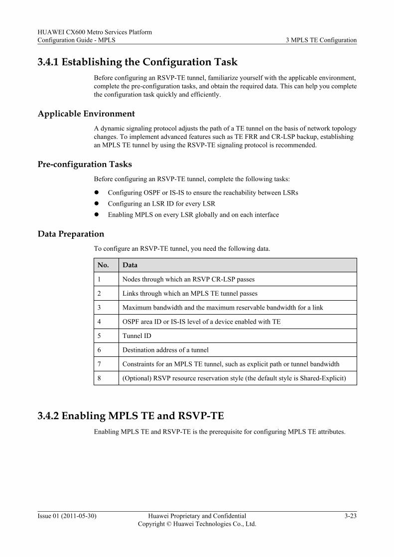
3.4.1 Establishing the Configuration TaskBefore configuring an RSVP-TE tunnel, familiarize yourself with the applicable environment,complete the pre-configuration tasks, and obtain the required data. This can help you completethe configuration task quickly and efficiently.
Applicable EnvironmentA dynamic signaling protocol adjusts the path of a TE tunnel on the basis of network topologychanges. To implement advanced features such as TE FRR and CR-LSP backup, establishingan MPLS TE tunnel by using the RSVP-TE signaling protocol is recommended.
Pre-configuration TasksBefore configuring an RSVP-TE tunnel, complete the following tasks:
l Configuring OSPF or IS-IS to ensure the reachability between LSRsl Configuring an LSR ID for every LSRl Enabling MPLS on every LSR globally and on each interface
Data PreparationTo configure an RSVP-TE tunnel, you need the following data.
No. Data
1 Nodes through which an RSVP CR-LSP passes
2 Links through which an MPLS TE tunnel passes
3 Maximum bandwidth and the maximum reservable bandwidth for a link
4 OSPF area ID or IS-IS level of a device enabled with TE
5 Tunnel ID
6 Destination address of a tunnel
7 Constraints for an MPLS TE tunnel, such as explicit path or tunnel bandwidth
8 (Optional) RSVP resource reservation style (the default style is Shared-Explicit)
3.4.2 Enabling MPLS TE and RSVP-TEEnabling MPLS TE and RSVP-TE is the prerequisite for configuring MPLS TE attributes.
HUAWEI CX600 Metro Services PlatformConfiguration Guide - MPLS 3 MPLS TE Configuration
Issue 01 (2011-05-30) Huawei Proprietary and ConfidentialCopyright © Huawei Technologies Co., Ltd.
3-23
ContextNOTE
l If MPLS TE is disabled in the interface view, all CR-LSPs on the current interface go Down.
l If MPLS TE is disabled in the MPLS view, MPLS TE on each interface is disabled and all CR-LSPsgo Down.
l If RSVP-TE on a node is disabled, RSVP-TE on all interfaces of this node is disabled.
Do as follows on each node along a TE tunnel:
Procedure
Step 1 Run:system-view
The system view is displayed.
Step 2 Run:mpls
The MPLS view is displayed.
Step 3 Run:mpls te
MPLS TE is enabled on the node globally.
Step 4 Run:mpls rsvp-te
RSVP-TE is enabled on the node globally.
Step 5 Run:quit
Return to the system view.
Step 6 Run:interface interface-type interface-number
The interface view of the MPLS-TE-enabled interface is displayed.
Step 7 Run:mpls te
MPLS TE is enabled on the interface.
Step 8 Run:mpls rsvp-te
RSVP-TE is enabled on the interface.
----End
3.4.3 (Optional) Configuring Link BandwidthBy configuring the link bandwidth, you can set the bandwidth of a CR-LSP.
3 MPLS TE ConfigurationHUAWEI CX600 Metro Services Platform
Configuration Guide - MPLS
3-24 Huawei Proprietary and ConfidentialCopyright © Huawei Technologies Co., Ltd.
Issue 01 (2011-05-30)
ContextNOTE
To constrain the bandwidth of CR-LSPs, the procedure is mandatory. In addition, the mpls te lsp-tpoutbound command must be run on the corresponding tunnel interface.
By default, the maximum reservable bandwidth on the link is 0 bit/s. If the maximum reservable bandwidthis not configured, when the bandwidth of the CR-LSP is constrained, the bandwidth of the CR-LSP is morethan the maximum reservable bandwidth. Therefore, the CR-LSP cannot be set up.
Do as follows on each node along the CR-LSP:
Procedure
Step 1 Run:system-view
The system view is displayed.
Step 2 Run:interface interface-type interface-number
The MPLS-TE-enabled interface view is displayed.
Step 3 Run:mpls te bandwidth max-reservable-bandwidth bw-value
The maximum available bandwidth of the link is configured.
Step 4 Run:mpls te bandwidth { bc0 bc0-bw-value | bc1 bc1-bw-value }*
The BC bandwidth of the link is configured.
NOTE
l The maximum reservable bandwidth of a link cannot be greater than the actual bandwidth of the link.A maximum of 80% of the actual bandwidth of the link is recommended for the maximum reservablebandwidth of the link.
l Neither the BC0 bandwidth nor the BC1 bandwidth can be greater than the maximum reservablebandwidth of the link.
l If an MPLS TE tunnel to be set up requires the bandwidth that is larger than 67105 kbit/s, it isrecommended that the reserved bandwidth be one thousandth more that the bandwidth to be configured.
----End
3.4.4 Configuring OSPF TEA Traffic Engineering DataBase (TEDB) will be generated on a network if OSPF TE isconfigured. After OSPF TE is configured, a CR-LSP is established by using OSPF routes notthe routes calculated by CSPF.
ContextBy default, an OSPF area does not support TE.
The OSPF TE extension uses Opaque Type 10 LSA to carry the TE attribute of a link. Therefore,the Opaque capability of OSPF must be enabled. TE LSAs are generated only when at least oneneighbor is in the FULL state.
HUAWEI CX600 Metro Services PlatformConfiguration Guide - MPLS 3 MPLS TE Configuration
Issue 01 (2011-05-30) Huawei Proprietary and ConfidentialCopyright © Huawei Technologies Co., Ltd.
3-25
NOTE
If OSPF TE is not configured, no TE LSA exists and thus no TEDB is generated on a network. In this case,a CR-LSP is established by using IGP routes not routes calculated by CSPF calculation.
Do as follows on each node along a TE tunnel:
Procedure
Step 1 Run:system-view
The system view is displayed.
Step 2 Run:ospf [ process-id ]
The OSPF view is displayed.
Step 3 Run:opaque-capability enable
The OSPF opaque capability is enabled.
Step 4 (Optional) Run:advertise mpls-lsr-id
The MPLS LSR ID is advertised to multiple OSPF areas. This step is necessary only on an AreaBorder Router (ABR) in multiple OSPF areas.
Step 5 Run:area area-id
The OSPF area view is displayed.
Step 6 Run:mpls-te enable [ standard-complying ]
TE is enabled in the current OSPF area.
----End
3.4.5 Configuring IS-IS TEA TEDB will be generated on a network only if IS-IS TE is configured. After IS-IS TE isconfigured, a CR-LSP is established by using IS-IS routes not the routes calculated by CSPF.
ContextDo as follows on each node along a TE tunnel:
Procedure
Step 1 Run:system-view
The system view is displayed.
Step 2 Run:
3 MPLS TE ConfigurationHUAWEI CX600 Metro Services Platform
Configuration Guide - MPLS
3-26 Huawei Proprietary and ConfidentialCopyright © Huawei Technologies Co., Ltd.
Issue 01 (2011-05-30)
isis [ process-id ]
The IS-IS view is displayed.
Step 3 Run:cost-style { compatible [ relax-spf-limit ] | wide | wide-compatible }
The IS-IS Wide Metric attribute is configured.
The IS-IS TE extension uses a sub-TLV of IS-reachable TLV (22) to carry TE attributes. TheIS-IS Wide Metric attribute configured as wide, compatible or wide-compatible. By default, IS-IS sends or receives packets that express route metric in Narrow mode.
Step 4 Run:traffic-eng [ level-1 | level-2 | level-1-2 ]
IS-IS TE is enabled.
By default, IS-IS does not support TE.
If a level is not specified after IS-IS TE is enabled, IS-IS TE is valid for both Level-1 and Level-2.
Step 5 (Optional) Run:te-set-subtlv { bw-constraint value | lo-multiplier value | unreserve-bw-sub-pool value }*
The TLV type for the sub-TLVs used to carry the DS-TE parameters is set.
By default, the BW-constraint sub-TLV is 252; the Local Overbooking Multipliers (LOM) sub-TLV is 253; the unreserve-BW-sub-pool sub-TLV is 251.
----End
3.4.6 (Optional) Configuring an MPLS TE Explicit PathAn explicit path is created, over which a CR-LSP is established.
ContextAn explicit path consists of a series of nodes. These nodes form a vector path in the sequenceof configuration.
The IP address of an explicit path is the IP address of an interface on the node. Often, the IPaddress of a loopback interface on the egress node is used as the destination address of the explicitpath.
Adjacent nodes are connected in the following modes on an explicit path:
l Strict: The two nodes are connected directly.l Loose: Other LSRs may exist between the two nodes.
The strict mode and the loose mode are used separately or together.
By default, the include strict mode is used. This means that the next hop added to the explicitpath must be directly connected to the previous node. A constraint for an explicit path is that thenodes through which traffic must pass or cannot pass are selectable.
include indicates that an established LSP must pass through the specified nodes.
exclude indicates that an established LSP cannot pass through the specified nodes.
HUAWEI CX600 Metro Services PlatformConfiguration Guide - MPLS 3 MPLS TE Configuration
Issue 01 (2011-05-30) Huawei Proprietary and ConfidentialCopyright © Huawei Technologies Co., Ltd.
3-27
TE tunnels are classified into intra-area tunnels and inter-area tunnels.
l Intra-area tunnel: indicates that TE tunnels are in a single area. An area is either an OSPFarea or an IS-IS area, not a BGP AS.
l Inter-area tunnel: indicates that TE tunnels traverse through multiple areas. Areas are OSPFareas or IS-IS areas not BGP ASs.
A loose explicit path must be used to establish an inter-area TE tunnel and the next node of theexplicit path must be an ABR or an ASBR.
Do as follows on the ingress of a TE tunnel:
ProcedureStep 1 Run:
system-view
The system view is displayed.
Step 2 Run:explicit-path path-name
The explicit path is created and the explicit path view is displayed.
Step 3 Run:next hop ip-address [ include [ strict | loose ] | exclude ]
The next IP address of the explicit path is specified.
Step 4 Run:add hop ip-address1 [ include [ strict | loose ] | exclude ] { after | before } ip-address2
A node is added to the explicit path.
Step 5 Run:modify hop ip-address1 ip-address2 [ include [ strict | loose ] | exclude ]
The address of a node on the explicit path is modified.
Step 6 Run:delete hop ip-address
A node is deleted from the explicit path.
Step 7 Run:list hop [ ip-address ]
Information about the explicit path is displayed.
----End
3.4.7 Configuring the MPLS TE Tunnel InterfaceA tunnel interface must be created and tunnel configurations must be configured on the tunnelinterface before an RSVP-TE tunnel is established.
ContextDo as follows on the ingress node of a TE tunnel:
3 MPLS TE ConfigurationHUAWEI CX600 Metro Services Platform
Configuration Guide - MPLS
3-28 Huawei Proprietary and ConfidentialCopyright © Huawei Technologies Co., Ltd.
Issue 01 (2011-05-30)
Procedure
Step 1 Run:system-view
The system view is displayed.
Step 2 Run:interface tunnel interface-number
A tunnel interface is created and the tunnel interface view is displayed.
CAUTIONConfiguring a tunnel interface on the main control board is recommended. The slot ID of themain control board is the slot ID in tunnel-number, which is usually 0. In the situation where atunnel interface is configured on an interface board, the tunnel interface will be deleted if theinterface board is restarted.
Step 3 To configure the IP address of a tunnel interface, run one of the following commands.l To assign an IP address to the tunnel interface, run:
ip address ip-address { mask | mask-length } [ sub ]
The secondary IP address of the tunnel interface is configured only after the primary IPaddress is configured.
l To use an unnumbered IP address, run:ip address unnumbered interface interface-type interface-number
A tunnel interface must have an IP address to forward traffic. It is unnecessary to configure anIP address separately for the tunnel interface as an MPLS TE tunnel is unidirectional. The tunnelinterface often borrows the LSR ID of the ingress node as the address.
NOTE
Because the type of the packet forwarded by the MPLS TE tunnel is MPLS, the commands, such as ipurpf commands, related to IP packet forwarding configured on this interface are invalid.
Step 4 Run:tunnel-protocol mpls te
MPLS TE is configured as a tunnel protocol.
Step 5 Run:destination ip-address
The destination address of a tunnel is configured, which is usually the LSR ID of the egressnode.
Different types of tunnels have different requirements for a destination address. If the tunnelprotocol is changed to MPLS TE, the configuration of the destination command is deletedautomatically and needs to be re-configured.
Step 6 Run:mpls te tunnel-id tunnel-id
The tunnel ID is configured.
HUAWEI CX600 Metro Services PlatformConfiguration Guide - MPLS 3 MPLS TE Configuration
Issue 01 (2011-05-30) Huawei Proprietary and ConfidentialCopyright © Huawei Technologies Co., Ltd.
3-29
Step 7 Run:mpls te signal-protocol rsvp-te
RSVP-TE is configured as the signaling protocol for a tunnel.
Step 8 Run:mpls te commit
The current tunnel configuration is committed.
NOTE
If MPLS TE parameters on a tunnel interface are changed, run the mpls te commit command to make themtake effect.
----End
3.4.8 Configuring Constraints for an MPLS TE TunnelA path over which an RSVP-TE tunnel is set up is precisely controlled by configuring constraintrules such as an explicit path.
ContextDo as follows on the ingress of a TE tunnel:
Procedure
Step 1 Run:system-view
The system view is displayed.
Step 2 Run:interface tunnel tunnel-number
The tunnel interface view of the MPLS TE tunnel is displayed.
Step 3 Run:mpls te bandwidth [ ct0 ct0-bw-value | ct1 ct1-bw-value ] [ flow-queue flow-queue ]
The bandwidth is configured for the tunnel.
The bandwidth used by the tunnel cannot exceed the maximum reservable bandwidth of the link.
The default bandwidth type of the tunnel is ct0.
If only a specified transmission path, not the bandwidth, needs to be configured for the TE tunnel,this step is unnecessary.
Step 4 Run:mpls te path explicit-path path-name
The explicit path used by the MPLS TE tunnel is configured.
If only the bandwidth, not the transmission path, needs to be configured for the TE tunnel, thisstep is unnecessary.
Step 5 Run:
3 MPLS TE ConfigurationHUAWEI CX600 Metro Services Platform
Configuration Guide - MPLS
3-30 Huawei Proprietary and ConfidentialCopyright © Huawei Technologies Co., Ltd.
Issue 01 (2011-05-30)
mpls te commit
The current tunnel configuration is committed.
If the bandwidth for the MPLS TE tunnel is higher than 28630 kbit/s, the assigned bandwidthof the MPLS TE tunnel may not be precise, and the MPLS TE tunnel can still be set upsuccessfully.
----End
3.4.9 (Optional) Configuring RSVP Resource Reservation StyleBy configuring a resource reservation style, you can configure different LSPs over the same linkto use the same or different reserved resources.
Context
Do as follows on the ingress of a TE tunnel:
Procedure
Step 1 Run:system-view
The system view is displayed.
Step 2 Run:interface tunnel tunnel-number
The tunnel interface view of the MPLS TE tunnel is displayed.
Step 3 Run:mpls te resv-style { ff | se }
The resource reservation style for the tunnel is specified.
By default, the resource reservation style is the Shared-Explicit (SE) style.
In TE applications, the SE style is used in the make-before-break mechanism, and the Fixed-Filter (FF) style is seldom used.
Step 4 Run:mpls te commit
The tunnel configuration is committed.
----End
3.4.10 Configuring CSPFAn IGP uses SPF to calculate the shortest path to each node on a network; MPLS TE uses CSPFto calculate the path to a certain node.
Context
Do as follows on the ingress of a TE tunnel:
HUAWEI CX600 Metro Services PlatformConfiguration Guide - MPLS 3 MPLS TE Configuration
Issue 01 (2011-05-30) Huawei Proprietary and ConfidentialCopyright © Huawei Technologies Co., Ltd.
3-31
NOTEConfiguring CSPF on all the transit nodes is recommended, preventing incomplete path computation onthe ingress.
Procedure
Step 1 Run:system-view
The system view is displayed.
Step 2 Run:mpls
The MPLS view is displayed.
Step 3 Run:mpls te cspf
CSPF on the local LSR is enabled.
Step 4 (Optional) Run:mpls te cspf preferred-igp { isis | ospf }
The preferred IGP protocol is configured.
By default, CSPF is disabled.
----End
3.4.11 Checking the ConfigurationAfter the configuration of an RSVP-TE tunnel, you can view statistics about the RSVP-TE tunneland its status.
PrerequisiteThe configurations of the RSVP-TE tunnel function are complete.
Procedurel Run the display mpls te link-administration bandwidth-allocation [ interface interface-
type interface-number ] command to check the allocation of the link bandwidth.l Run the display ospf [ process-id ] mpls-te [ area area-id ] [ self-originated ] command
to check OSPF TE information.l Run the display isis traffic-eng advertisements [ { level-1 | level-2 | level-1-2 } | { lsp-
id | local } ] * [ process-id | vpn-instance vpn-instance-name ] command to check the IS-IS TE status.
l Run the display isis traffic-eng link [ { level-1 | level-2 | level-1-2 } | verbose ] * [ process-id | vpn-instance vpn-instance-name ] command to check the IS-IS TE status.
l Run the display isis traffic-eng network [ level-1 | level-2 | level-1-2 ] [ process-id | vpn-instance vpn-instance-name ] command to check the IS-IS TE status.
l Run the display isis traffic-eng statistics [ process-id | vpn-instance vpn-instance-name ] command to check the IS-IS TE status.
3 MPLS TE ConfigurationHUAWEI CX600 Metro Services Platform
Configuration Guide - MPLS
3-32 Huawei Proprietary and ConfidentialCopyright © Huawei Technologies Co., Ltd.
Issue 01 (2011-05-30)
l Run the display isis traffic-eng sub-tlvs [ process-id | vpn-instance vpn-instance-name ] command to check the IS-IS TE status.
l Run the display explicit-path [ path-name ] [ verbose ] command to check the explicitpath.
l Run the display mpls te cspf destination ip-address [ affinity properties [ mask mask-value ] | bandwidth { ct0 ct0-bandwidth | ct1 ct1-bandwidth | ct2 ct2-bandwidth | ct3 ct3-bandwidth | ct4 ct4-bandwidth | ct5 ct5-bandwidth | ct6 ct6-bandwidth | ct7 ct7-bandwidth }* | explicit-path path-name | hop-limit hop-limit-number | metric-type{ igp | te } | priority setup-priority | srlg-strict exclude-path-name | tie-breaking{ random | most-fill | least-fill } ]* command to check path information for CSPF.
l Run the display mpls te cspf tedb { all | area area-id | interface ip-address | network-lsa | node [ router-id ] } command to check TEDB information for CSPF.
l Run the display mpls rsvp-te [ interface [ interface-type interface-number ] ] commandto check information about RSVP.
l Run the display mpls rsvp-te established [ interface interface-type interface-numberpeer-ip-address ] command to check the established RSVP-TE tunnel.
l Run the display mpls rsvp-te peer [ interface interface-type interface-number ] commandto check RSVP information of neighbors.
l Run the display mpls rsvp-te reservation [ interface interface-type interface-numberpeer-ip-address ] command to check the RSVP reserved resource.
l Run the display mpls rsvp-te request [ interface interface-type interface-number peer-ip-address ] command to check information about the resources that are requsted.
l Run the display mpls rsvp-te sender [ interface interface-type interface-number peer-ip-address ] command to check information about the RSVP sender.
l Run the display mpls rsvp-te statistics { global | interface [ interface-type interface-number ] } command to check statistics about RSVP-TE.
l Run the display mpls te link-administration admission-control [ interface interface-type interface-number | stale-interface interface-index ] command to check the tunnelpermitted by the local node.
l Run the display mpls te tunnel [ destination ip-address ] [ lsp-id ingress-lsr-id session-id local-lsp-id | lsr-role { all | egress | ingress | remote | transit } ] [ name tunnel-name ][ { incoming-interface | interface | outgoing-interface } interface-type interface-number ] [ verbose ] command to check tunnel information.
l Run the display mpls te tunnel statistics or display mpls lsp statistics command to checktunnel statistics.
l Run the display mpls te tunnel-interface [ tunnel tunnel-number ] command to check thetunnel interface on the ingress.
----End
Example
If the configurations succeed, run the preceding commands, and you can view the followinginformation:
l Information about links, including the physical bandwidth and available bandwidth of thelink
l Information about OSPF TE LSAs generated by every node
HUAWEI CX600 Metro Services PlatformConfiguration Guide - MPLS 3 MPLS TE Configuration
Issue 01 (2011-05-30) Huawei Proprietary and ConfidentialCopyright © Huawei Technologies Co., Ltd.
3-33
l Information about IS-IS TE on every node
l Information about MPLS RSVP-TE timers, the status of interfaces enabled RSVP-TE, thebandwidth, the parameters for RSVP neighbors, sender information, and statistics
l Tunnel name, incoming and outgoing labels, and incoming and outgoing interfaces.
l Tunnel status statistics on the LSR
l Detailed information about the tunnel interface on the tunnel ingress, including the tunnel'sname, status, and attributes (including the LSP ID, ingress, and egress)
3.5 Referencing the CR-LSP Attribute Template to Set Up aCR-LSP
By configuring a CR-LSP attribute template to set up CR-LSPs, you can simply theconfigurations and make the configurations of CR-LSPs more flexible.
3.5.1 Establishing the Configuration TaskBefore using a CR-LSP attribute template to set up a CR-LSP, familiarize yourself with theapplicable environment, complete the pre-configuration tasks, and obtain the data required forthe configuration. This will help you complete the configuration task quickly and accurately.
3.5.2 Configuring a CR-LSP Attribute TemplateYou need to configure a CR-LSP attribute template before using the CR-LSP attribute templateto set up a CR-LSP.
3.5.3 Setting Up a CR-LSP by Using a CR-LSP Attribute TemplateYou can use a CR-LSP attribute template to set up the primary CR-LSP, hot-standby CR-LSP,and ordinary backup CR-LSP.
3.5.4 Checking the ConfigurationAfter referencing a CR-LSP attribute template to set up CR-LSPs, you can view informationabout the established MPLS TE CR-LSPs.
3.5.1 Establishing the Configuration TaskBefore using a CR-LSP attribute template to set up a CR-LSP, familiarize yourself with theapplicable environment, complete the pre-configuration tasks, and obtain the data required forthe configuration. This will help you complete the configuration task quickly and accurately.
Applicable Environment
You can create a CR-LSP by using the following methods:
l Creating a CR-LSP without using a CR-LSP attribute template
l Creating a CR-LSP by using a CR-LSP attribute template
It is recommended to use a CR-LSP attribute template to set up a CR-LSP because thismethod has the following advantages:
– A CR-LSP attribute template can greatly simplify the configurations of CR-LSPs.
– A maximum of three CR-LSP attribute templates can be created for a hot-standby CR-LSP or an ordinary backup CR-LSP; thus, you can set up a hot-standby CR-LSP or anordinary backup CR-LSP with different path options. (Among the three attribute
3 MPLS TE ConfigurationHUAWEI CX600 Metro Services Platform
Configuration Guide - MPLS
3-34 Huawei Proprietary and ConfidentialCopyright © Huawei Technologies Co., Ltd.
Issue 01 (2011-05-30)
templates, the template with the smallest sequence number is firstly used. If the setupfails, the template with a greater sequence number is used.)
– If configurations of a CR-LSP attribute template are modified, configurations of theCR-LSPs established by using the CR-LSP attribute template are automatically updated,which makes the configurations of CR-LSPs more flexible.
NOTE
The preceding two methods can be used together. If the TE attribute configured in the tunnel interface viewand the TE attribute configured through a CR-LSP attribute template coexist, the former takes precedenceover the latter.
Pre-configuration TasksBefore using a CR-LSP attribute template to set up a CR-LSP, complete the following tasks:
l Configuring an IGP on the P and PE on the MPLS backbone network to ensure IPconnectivity
l Enable MPLS, MPLS TE, and RSVP TE on the MPLS backbone network
Data PreparationTo use a CR-LSP attribute template to set up a CR-LSP, you need the following data.
No. Data
1 Names of the primary CR-LSP attribute template, hot-standby CR-LSP attributetemplate, or ordinary backup CR-LSP attribute template
2 (Optional) Bandwidth of the CR-LSP attribute template
3 (Optional) Name of the explicit path referenced by the CR-LSP attributetemplate
4 (Optional) Affinity value and affinity mask of the CR-LSP attribute template
5 (Optional) Setup priority and hold priority of the CR-LSP attribute template
6 (Optional) Hop limit of the CR-LSP attribute template
7 Tunnel interface which will use the attribute template
8 Sequence of using the hot-standby CR-LSP attribute template and ordinarybackup CR-LSP attribute template
3.5.2 Configuring a CR-LSP Attribute TemplateYou need to configure a CR-LSP attribute template before using the CR-LSP attribute templateto set up a CR-LSP.
ContextDo as follows on the ingress of the CR-LSP:
Steps 3 to 10 are optional.
HUAWEI CX600 Metro Services PlatformConfiguration Guide - MPLS 3 MPLS TE Configuration
Issue 01 (2011-05-30) Huawei Proprietary and ConfidentialCopyright © Huawei Technologies Co., Ltd.
3-35
Procedure
Step 1 Run:system-view
The system view is displayed.
Step 2 Run:lsp-attribute lsp-attribute-name
A CR-LSP attribute template is created and the LSP attribute view is displayed.
NOTE
A CR-LSP attribute template can be deleted only when it is not used by any tunnel interface.
Step 3 (Optional) Run:bandwidth { ct0 bandwidth | ct1 bandwidth | ct2 bandwidth | ct3 bandwidth | ct4 bandwidth | ct5 bandwidth | ct6 bandwidth | ct7 bandwidth }*
The bandwidth is set for the CR-LSP attribute template. The optional bandwidth type varies withDS-TE modes. In non-DS-TE mode, only CT0 and CT1 are supported. In DS-TE mode, if noTE-Class mapping table is configured, only CT0, CT1, CT2, and CT3 are supported; if a TE-Class mapping table is configured, the CT types configured in the TE-Class mapping table areadopted.
NOTE
If an MPLS TE tunnel to be set up requires a bandwidth larger than 67105 kbit/s, it is recommended thatthe 1/1000 of the configured bandwidth to be reserved.
Step 4 (Optional) Run:explicit-path path-name
An explicit path is configured for the CR-LSP attribute template.
Step 5 (Optional) Run:affinity property affinity-value [ mask mask-value ]
The affinity attribute is set for the CR-LSP attribute template.
By default, both the affinity value and the affinity mask are 0x0.
Step 6 (Optional) Run:priority setup_priority_value [ hold_priority_value ]
The setup priority and hold priority are set for the CR-LSP attribute template.
By default, both the setup priority and the hold priority are 7.
Step 7 (Optional) Run:hop-limit hop-limit
The hop limit is set for the CR-LSP attribute template.
By default, the hop limit is 32.
Step 8 (Optional) Run:fast-reroute [ bandwidth ]
FRR is enabled for the CR-LSP attribute template.
By default, FRR is disabled.
3 MPLS TE ConfigurationHUAWEI CX600 Metro Services Platform
Configuration Guide - MPLS
3-36 Huawei Proprietary and ConfidentialCopyright © Huawei Technologies Co., Ltd.
Issue 01 (2011-05-30)
NOTE
Before enabling or disabling FRR for the CR-LSP attribute template, note the following:
l After FRR is enabled, the route recording function is automatically enabled for the CR-LSP.
l After FRR is disabled, attributes of the bypass tunnel are automatically deleted.
Step 9 (Optional) Run:record-route [ label ]
The route recording function is enabled for the CR-LSP attribute template.
By default, the route recording function is disabled.
NOTE
The undo mpls te record-route command can take effect only when FRR is disabled.
Step 10 (Optional) Run:bypass-attributes { bandwidth bandwidth | priority setup_priority_value [ hold_priority_value ] }
The bypass tunnel attributes are configured for the CR-LSP attribute template.
By default, the bypass tunnel attributes are not configured.
NOTEThis command can take effect only when the following conditions are met:
l The CR-LSP attribute template has been enabled with FRR allowing bandwidth protection.
l The bandwidth for the bypass tunnel is lower than or equal to the bandwidth for the CR-LSP attributetemplate.
l The setup priority and hold priority of the bypass tunnel are smaller than the setup priority and holdpriority of the CR-LSP attribute template.
Step 11 Run:commit
Configurations of the CR-LSP attribute template are committed.
NOTE
When the CR-LSP attribute template is used to set up a CR-LSP:
l The CR-LSP is removed and a new CR-LSP is created if the Break-Before-Make attribute (the priorityattribute) of the CR-LSP attribute template is modified.
l The CR-LSP is removed after an eligible CR-LSP is created and traffic switches to the new CR-LSPif the Make-Before-Break attribute of the CR-LSP attribute template is modified.
----End
3.5.3 Setting Up a CR-LSP by Using a CR-LSP Attribute TemplateYou can use a CR-LSP attribute template to set up the primary CR-LSP, hot-standby CR-LSP,and ordinary backup CR-LSP.
Context
Do as follows on the ingress of the CR-LSP:
HUAWEI CX600 Metro Services PlatformConfiguration Guide - MPLS 3 MPLS TE Configuration
Issue 01 (2011-05-30) Huawei Proprietary and ConfidentialCopyright © Huawei Technologies Co., Ltd.
3-37
Procedure
Step 1 Run:system-view
The system view is display.
Step 2 Run:interface tunnel tunnel-number
The tunnel interface view is displayed.
To configure the TE tunnel interface, refer to the section Configuring MPLS TE TunnelInterfaces.
Step 3 Run:mpls te primary-lsp-constraint { dynamic | lsp-attribute lsp-attribute-name }
The primary CR-LSP is set up through the specified CR-LSP attribute template.
If dynamic is used, it indicates that when a CR-LSP attribute template is used to set up a primaryCR-LSP, all attributes in the template adopt the default values.
Step 4 (Optional) Run:mpls te hotstandby-lsp-constraint number { dynamic | lsp-attribute lsp-attribute-name }
The hot-standby CR-LSP is set up by using the specified CR-LSP attribute template.
A maximum of three CR-LSP attribute templates can be used to set up a hot-standby CR-LSP.The hot-standby CR-LSP must be consistent with the primary CR-LSP in the attributes of thesetup priority, hold priority, and bandwidth type. To set up a hot-standby CR-LSP, you shouldkeep on attempting to use CR-LSP attribute templates one by one in ascending order of thenumber of the attribute templates until the hot-standby CR-LSP is set up.
If dynamic is used, it indicates that the hot-standby CR-LSP is assigned the same bandwidthand priority as the primary CR-LSP, but specified with a different path from the primary CR-LSP.
Step 5 (Optional) Run:mpls te backup hotstandby-lsp-constraint wtr interval
The Wait to Restore (WTR) time is set for the traffic to switch back from the hot-standby CR-LSP to the primary CR-LSP.
By default, the WTR time for the traffic to switch back from the hot-standby CR-LSP to theprimary CR-LSP is 10 seconds.
NOTE
The hot-standby CR-LSP specified in the mpls te backup hotstandby-lsp-constraint wtr command mustbe an existing one established by running the mpls te hotstandby-lsp-constraint command.
Step 6 (Optional) Run:mpls te ordinary-lsp-constraint number { dynamic | lsp-attribute lsp-attribute-name }
The ordinary backup CR-LSP is set up by using the specified CR-LSP attribute template.
A maximum of three CR-LSP attribute templates can be used to set up an ordinary backup CR-LSP. The ordinary backup CR-LSP must be consistent with the primary CR-LSP in the attributes
3 MPLS TE ConfigurationHUAWEI CX600 Metro Services Platform
Configuration Guide - MPLS
3-38 Huawei Proprietary and ConfidentialCopyright © Huawei Technologies Co., Ltd.
Issue 01 (2011-05-30)
of the setup priority, hold priority, and bandwidth type. To set up an ordinary backup CR-LSP,you should keep on attempting to use CR-LSP attribute templates one by one in ascending orderof the number of the attribute template until the ordinary backup CR-LSP is set up.
If dynamic is used, it indicates that the ordinary backup CR-LSP is assigned the same bandwidthand priority as the primary CR-LSP.
Step 7 Run:mpls te commit
The configurations of the CR-LSP are committed.
----End
3.5.4 Checking the ConfigurationAfter referencing a CR-LSP attribute template to set up CR-LSPs, you can view informationabout the established MPLS TE CR-LSPs.
PrerequisiteAll configurations of the CR-LSP set up by using the CR-LSP attribute template are complete.
Procedure
Step 1 Run the display explicit-path [ path-name ] [ tunnel-interface | lsp-attribute | verbose ]command to view information about the explicit path configured for the CR-LSP attributetemplate.
Step 2 Run the display mpls te tunnel-interface lsp-constraint [ tunnel tunnel-number ] commandto view information about the CR-LSP attribute template on the TE tunnel interface.
Step 3 Run the display mpls te tunnel-interface [ auto-bypass-tunnel tunnel-name | tunnel tunnel-number ] command to view information about the MPLS TE tunnel using the CR-LSP attributetemplate.
----End
Example
If the configurations succeed, you can view the following information:
l List of CR-LSP attribute templates that use the specified explicit path
l Information about the CR-LSP attribute templates on the specified TE tunnel interface
l Information about the CR-LSPs that are set up through the specified CR-LSP attributetemplate
3.6 Adjusting RSVP Signaling ParametersRSVP-TE provides various parameters, which meet the requirements for reliability, networkresources, and advanced MPLS features.
3.6.1 Establishing the Configuration Task
HUAWEI CX600 Metro Services PlatformConfiguration Guide - MPLS 3 MPLS TE Configuration
Issue 01 (2011-05-30) Huawei Proprietary and ConfidentialCopyright © Huawei Technologies Co., Ltd.
3-39
Before adjusting RSVP signaling parameters, familiarize yourself with the applicableenvironment, complete the pre-configuration tasks, and obtain the required data. This can helpyou complete the configuration task quickly and accurately.
3.6.2 Configuring RSVP Hello ExtensionThe RSVP Hello extension mechanism can detect reachability of RSVP neighbors.
3.6.3 Configuring RSVP TimersBy configuring the RSVP status timer, you can set the refresh interval of Path messages andResv messages and the timeout multiplier when RSVP is in the blocked state.
3.6.4 Configuring RSVP Refresh MechanismEnabling Srefresh on the interface that connects two neighboring devices can reduce the costand improve the performance. After Srefresh is enabled, the retransmission of Srefresh messagesis automatically enabled on the interface.
3.6.5 Enabling Reservation Confirmation MechanismReceiving an ResvConf message does not mean that the resource reservation succeeds. It meansthat resources are reserved successfully only on the farthest upstream node where this Resvmessage arrives. These resources, however, may be preempted by other applications later.
3.6.6 Checking the ConfigurationAfter adjusting RSVP signaling parameters, you can view the refresh parameters, the status ofRSVP reservation confirmation and RSVP Hello extension, and the RSVP status timerconfiguration.
3.6.1 Establishing the Configuration TaskBefore adjusting RSVP signaling parameters, familiarize yourself with the applicableenvironment, complete the pre-configuration tasks, and obtain the required data. This can helpyou complete the configuration task quickly and accurately.
Applicable Environment
RSVP TE supports diversified signaling parameters. It ensures reliability and network resourceefficiency, and offers certain MPLS TE advanced features.
Before performing the configuration tasks described in this section, you must know in detail thepurpose of each task and the influences they have on networks.
Pre-configuration Tasks
Before optimizing the RSVP-TE tunnel, complete the following task:
l Configuring RSVP-TE Tunnel
Data Preparation
To optimize the RSVP TE tunnel, you need the following data.
No. Data
1 Refresh interval of RSVP message
2 PSB, RSB, and BSB timeout multiplier of RSVP
3 MPLS TE ConfigurationHUAWEI CX600 Metro Services Platform
Configuration Guide - MPLS
3-40 Huawei Proprietary and ConfidentialCopyright © Huawei Technologies Co., Ltd.
Issue 01 (2011-05-30)
No. Data
3 Retransmission timer and increment of RSVP
4 Transmission interval and allowable maximum loss numbers of Hello messages
3.6.2 Configuring RSVP Hello ExtensionThe RSVP Hello extension mechanism can detect reachability of RSVP neighbors.
ContextDo as follows on each node along the TE tunnel:
Procedure
Step 1 Run:system-view
The system view is displayed.
Step 2 Run:mpls
The MPLS view is displayed.
Step 3 Run:mpls rsvp-te hello
RSVP Hello extension is enabled on this node.
By default, the RSVP hello extension is disabled.
Step 4 Run:mpls rsvp-te hello-lost times
The permitted maximum times of Hello message loss is set.
When the RSVP Hello extension is enabled, by default, Hello ACK messages cannot be receivedfor consecutive 3 times, exceeding which the link is regarded as faulty, and the TE tunnel is torndown.
Step 5 Run:mpls rsvp-te timer hello interval
The refresh interval of Hello messages is set.
When the RSVP Hello extension is enabled, by default, the refresh interval of Hello message is3 seconds.
If the refresh interval is modified, the modification takes effect after the timer times out.
Step 6 Run:quit
Return to the system view.
HUAWEI CX600 Metro Services PlatformConfiguration Guide - MPLS 3 MPLS TE Configuration
Issue 01 (2011-05-30) Huawei Proprietary and ConfidentialCopyright © Huawei Technologies Co., Ltd.
3-41
Step 7 Run:interface interface-type interface-number
The interface view of the RSVP-TE-enabled interface is displayed.
Step 8 Run:mpls rsvp-te hello
The RSVP Hello extension mechanism is enabled on the interface.
The RSVP Hello extension mechanism is used to detect the reachability of RSVP neighboringnodes. For details, refer to RFC 3209 and RFC 3473.
----End
3.6.3 Configuring RSVP TimersBy configuring the RSVP status timer, you can set the refresh interval of Path messages andResv messages and the timeout multiplier when RSVP is in the blocked state.
Context
Do as follows on each node along the TE tunnel:
Procedure
Step 1 Run:system-view
The system view is displayed.
Step 2 Run:mpls
The MPLS view is displayed.
Step 3 Run:mpls rsvp-te timer refresh interval
The interval for refreshing Path/Resv messages is set.
By default, the refresh interval of Path/Resv message is 30 seconds.
If the refresh interval is modified, the modification takes effect after the timer expires.
It is not recommended to set a long refresh interval or modify the refresh interval frequently.
Step 4 Run:mpls rsvp-te keep-multiplier number
The timeout multiplier of PSB and RSB is configured.
By default, the timeout multiplier of PSB and RSB is 3.
----End
3 MPLS TE ConfigurationHUAWEI CX600 Metro Services Platform
Configuration Guide - MPLS
3-42 Huawei Proprietary and ConfidentialCopyright © Huawei Technologies Co., Ltd.
Issue 01 (2011-05-30)
3.6.4 Configuring RSVP Refresh MechanismEnabling Srefresh on the interface that connects two neighboring devices can reduce the costand improve the performance. After Srefresh is enabled, the retransmission of Srefresh messagesis automatically enabled on the interface.
ContextEnabling Srefresh in the interface view or the mpls view on two nodes that are the neighbors ofeach other can reduce the cost and improve the performance of a network. In the interface view,Srefresh can be enabled only on this interface; in the MPLS view, Srefresh can be enabled onthe entire device. After Srefresh is enabled, the retransmission of Srefresh messages isautomatically enabled on the interface or the device.
Assume that a node initializes the retransmission interval as Rf seconds. If receiving no ACKmessage within Rf seconds, the node retransmits the RSVP message after (1 + Delta) x Rfseconds. The value of Delta depends on the link rate. The node retransmits the message until itreceives an ACK message or the times of retransmission reach the threshold (that is,retransmission increment value).
Procedure
Step 1 Run:system-view
The system view is displayed.
Step 2 Run one of the following commands to enter the interface view or the MPLS view.l To enter the interface view of the MPLS TE tunnel, run:
interface interface-type interface-numberThe Srefresh mechanism that is configured in the interface view takes effect only on thecurrent interface.
l To enter the MPLS view, run:mplsThe Srefresh mechanism that is configured in the MPLS view takes effect globally. TheSrefresh mechanism in MPLS view is applied to the TE FRR networking. By doing this,both the usage of network resources and the reliability of the Srefresh mechanism can beimproved.
Step 3 Run:mpls rsvp-te srefresh
Srefresh is enabled.
By default, Srefresh is disabled on the interface.
Step 4 (Optional) Run:mpls rsvp-te timer retransmission { increment-value increment | retransmit-value interval } *
The retransmission parameters are set.
By default, increment is set to 1, and interval is set to 500 milliseconds.
----End
HUAWEI CX600 Metro Services PlatformConfiguration Guide - MPLS 3 MPLS TE Configuration
Issue 01 (2011-05-30) Huawei Proprietary and ConfidentialCopyright © Huawei Technologies Co., Ltd.
3-43
3.6.5 Enabling Reservation Confirmation MechanismReceiving an ResvConf message does not mean that the resource reservation succeeds. It meansthat resources are reserved successfully only on the farthest upstream node where this Resvmessage arrives. These resources, however, may be preempted by other applications later.
ContextDo as follows on the egress of the TE tunnel:
Procedure
Step 1 Run:system-view
The system view is displayed.
Step 2 Run:mpls
The MPLS view is displayed.
Step 3 Run:mpls rsvp-te resvconfirm
The reservation confirmation mechanism is enabled.
The reservation confirmation is initiated by the receiver of Path message. An object that requiresconfirming the reservation is carried along the Resv message sent by the receiver.
NOTE
Receiving ResvConf messages does not mean that the resource reservation succeeds. It means that,however, resources are reserved successfully only on the farthest upstream node where this Resv messagearrives. These resources may be preempted by other applications later.
----End
3.6.6 Checking the ConfigurationAfter adjusting RSVP signaling parameters, you can view the refresh parameters, the status ofRSVP reservation confirmation and RSVP Hello extension, and the RSVP status timerconfiguration.
Procedurel Run the display mpls rsvp-te [ interface [ interface-type interface-number ] ] command
to check related information about RSVP-TE.l Run the display mpls rsvp-te psb-content [ ingress-lsr-id tunnel-id lsp-id ] command to
check information about RSVP-TE PSB.l Run the display mpls rsvp-te rsb-content [ ingress-lsr-id tunnel-id lsp-id ] command to
check information about RSVP-TE RSB.l Run the display mpls rsvp-te statistics { global | interface [ interface-type interface-
number ] } command to check RSVP-TE statistics.
----End
3 MPLS TE ConfigurationHUAWEI CX600 Metro Services Platform
Configuration Guide - MPLS
3-44 Huawei Proprietary and ConfidentialCopyright © Huawei Technologies Co., Ltd.
Issue 01 (2011-05-30)
ExampleIf the configurations succeed, run the preceding commands and you can view the followinginformation:
l Refresh parameters of the interfacel Confirmation of the resource reservation, the state of the Hello extension, and the
configurations of RSVP-TE status timers.
3.7 Configuring RSVP AuthenticationRSVP authentication prevents unauthorized nodes from setting up RSVP neighbor relationshipswith the local node and prevents spoofing of forged packets.
3.7.1 Establishing the Configuration TaskBefore configuring RSVP authentication, familiarize yourself with the applicable environment,complete the pre-configuration tasks, and obtain the data required for the configuration. Thiswill help you complete the configuration task quickly and accurately.
3.7.2 Configuring RSVP Key AuthenticationRSVP key authentication is performed on interfaces of two RSVP neighbors. The keysconfigured on the interfaces of the RSVP neighbors must be the same; otherwise, RSVPauthentication fails and the received RSVP packets are discarded.
3.7.3 (Optional) Configuring the RSVP Authentication LifetimeBy setting the RSVP authentication lifetime, you enable a device to retain an RSVP neighborrelationship for a specified period of time though no CR-LSP exists between the RSVPneighbors.
3.7.4 (Optional) Configuring the Handshake FunctionRSVP key authentication is the prerequisite for configuring the RSVP handshake function.
3.7.5 (Optional) Configuring the Message Window FunctionThe message window function is configured to prevent mis-sequence of RSVP messages.
3.7.6 Checking the ConfigurationAfter the configuration of RSVP key authentication, you can view information about RSVP-TEof a physical outgoing interface.
3.7.1 Establishing the Configuration TaskBefore configuring RSVP authentication, familiarize yourself with the applicable environment,complete the pre-configuration tasks, and obtain the data required for the configuration. Thiswill help you complete the configuration task quickly and accurately.
Applicable EnvironmentRSVP key authentication prevents an unauthorized node from setting up RSVP neighborrelationships with the local node or generating forged packets to attack the local node.
RSVP key authentication prevents the following unauthorized means of setting up RSVPneighbor relationships, protecting the local node from attacks (such as malicious reservation ofhigh bandwidth):
l An unauthorized node attempts to set up a neighbor relationship with the local node.
HUAWEI CX600 Metro Services PlatformConfiguration Guide - MPLS 3 MPLS TE Configuration
Issue 01 (2011-05-30) Huawei Proprietary and ConfidentialCopyright © Huawei Technologies Co., Ltd.
3-45
l A remote node generates and sends forged RSVP messages to set up a neighbor relationshipwith the local node.
The message window function and the handshake function, together with RSVP keyauthentication, prevent anti-replay attacks or authentication interruption between RSVPneighbors resulted from RSVP message mis-sequence during network congestion.
The RSVP authentication lifetime is configured, preventing unceasing RSVP authentication. Inthe situation where no CR-LSP exists between RSVP neighbors, the neighbor relationship iskept Up until the RSVP authentication lifetime expires.
Pre-configuration TasksBefore configuring RSVP authentication, complete the following task:
l Configuring an RSVP-TE Tunnel
Data PreparationTo configure RSVP authentication, you need the following data.
No. Data
1 RSVP authentication key
2 (Optional) Local password used in handshake authentication
3 (Optional) RSVP message window size (being 1 by default)
3.7.2 Configuring RSVP Key AuthenticationRSVP key authentication is performed on interfaces of two RSVP neighbors. The keysconfigured on the interfaces of the RSVP neighbors must be the same; otherwise, RSVPauthentication fails and the received RSVP packets are discarded.
ContextRSVP authentication uses authentication objects in RSVP messages to authenticate the RSVPmessages, preventing malicious attacks initiated by the modified or forged RSVP messages andimproving the network reliability and security.
The RSVP key authentication is configured either in the interface view or the MPLS RSVP-TEneighbor view:l In the interface view, RSVP key authentication configured is performed between directly-
connected nodes.l In the MPLS RSVP-TE neighbor view, the RSVP key authentication is performed between
neighboring nodes, which is recommended.
HMAC-MD5 or keychain authentication is enabled by configuring one of the following optionalparameters:l cipher: configures HMAC-MD5 authentication with keys displayed in cipher text.l plain: configures HMAC-MD5 authentication with keys displayed in plaintext.
3 MPLS TE ConfigurationHUAWEI CX600 Metro Services Platform
Configuration Guide - MPLS
3-46 Huawei Proprietary and ConfidentialCopyright © Huawei Technologies Co., Ltd.
Issue 01 (2011-05-30)
l keychain: configures keychain authentication by using a globally configured keychain.
NOTE
The MD5 authentication password that starts and ends with $@$@ is invalid, because $@$@ is used todistinguish old and new passwords.
Procedurel Configure RSVP key authentication in the interface view.
Do as follows on each interface between two directly-connected nodes:
NOTE
The configurations must be complete on either of the two directly-connected interfaces within aperiod of time three times the interval at which a Path Refresh message is sent; otherwise, the RSVPsession goes Down.
1. Run:system-view
The system view is displayed.2. Run:
interface interface-type interface-number
The view of the MPLS TE link interface is displayed.3. Run:
mpls rsvp-te authentication { { { cipher | plain } auth-key } | keychain keychain-name }
The authentication key is configured.
RSVP key authentication configured in the interface view takes effect only on thecurrent interface and has the lowest preference.
l Configure RSVP key authentication in the MPLS RSVP-TE neighbor view.
Do as follows on each neighboring node:
NOTE
The configurations must be complete on either of the two directly-connected interfaces within aperiod of time three times the interval at which a Path Refresh message is sent; otherwise, the RSVPsession goes Down.
1. Run:system-view
The system view is displayed.2. Run:
mpls rsvp-te peer ip-address
The MPLS RSVP-TE neighbor view is displayed.
– When ip-address is specified as an interface address but not the LSR ID of theRSVP neighbor, key authentication is based on this neighbor's interface address.This means that RSVP key authentication takes effect only on the specifiedinterface of the neighbor, providing high security. In this case, RSVP keyauthentication has the highest preference.
– When ip-address is specified as an address equal to the LSR ID of the RSVPneighbor, key authentication is based on the neighbor's LSR ID. This means that
HUAWEI CX600 Metro Services PlatformConfiguration Guide - MPLS 3 MPLS TE Configuration
Issue 01 (2011-05-30) Huawei Proprietary and ConfidentialCopyright © Huawei Technologies Co., Ltd.
3-47
RSVP key authentication takes effect on all interfaces of the neighbor. In this case,this RSVP key authentication has the higher preference than that configured in theinterface view, but has the lower preference than that configured based on theneighbor interface address.
3. Run:mpls rsvp-te authentication { { { cipher | plain } auth-key } | keychain keychain-name }
The authentication key is configured.
----End
3.7.3 (Optional) Configuring the RSVP Authentication LifetimeBy setting the RSVP authentication lifetime, you enable a device to retain an RSVP neighborrelationship for a specified period of time though no CR-LSP exists between the RSVPneighbors.
ContextRSVP neighbors to remain the neighbor relationship when no CR-LSP exists between them untilthe RSVP authentication lifetime expires. Configuring the RSVP authentication time does notaffect the existing CR-LSPs.
Do as follows on each node along the tunnel:
ProcedureStep 1 Run:
system-view
The system view is displayed.
Step 2 Run either of the following commands to enter the interface view or the MPLS RSVP-TEneighbor view:l To enter the interface view of an MPLS TE tunnel, run:
interface interface-type interface-numberThe RSVP authentication lifetime that is configured in the interface view takes effect onlyon the current interface.
l To enter the MPLS RSVP-TE neighbor view, run:mpls rsvp-te peer ip-address– If ip-address is specified as an interface address but not the LSR ID of the RSVP
neighbor, the RSVP authentication lifetime takes effect only on the interface.– If ip-address is specified as an address equal to the LSR ID, the RSVP authentication
lifetime takes effect on the entire device.
Step 3 Run:mpls rsvp-te authentication lifetime lifetime
The RSVP authentication lifetime is set.
lifetime is in the format of HH:MM:SS. The value ranges from 00:00:01 to 23:59:59. By default,the time is 00:30:00, that is, 30 minutes.
----End
3 MPLS TE ConfigurationHUAWEI CX600 Metro Services Platform
Configuration Guide - MPLS
3-48 Huawei Proprietary and ConfidentialCopyright © Huawei Technologies Co., Ltd.
Issue 01 (2011-05-30)
3.7.4 (Optional) Configuring the Handshake FunctionRSVP key authentication is the prerequisite for configuring the RSVP handshake function.
ContextDo as follows on each node along a tunnel:
Procedure
Step 1 Run:system-view
The system view is displayed.
Step 2 Run either of the following commands to enter the interface view or the MPLS RSVP-TEneighbor view:l To enter the interface view of the MPLS TE tunnel, run:
interface interface-type interface-numberThe handshake function that is configured in the interface view takes effect only on thecurrent interface.
l To enter the MPLS RSVP-TE neighbor view, run:mpls rsvp-te peer ip-address
– When ip-address is specified as an interface address but not the LSR ID of the RSVPneighbor, the handshake function is configured based on the neighbor interface address.In this case, the handshake function takes effect only on the interface.
– When ip-address is specified as an address equal to the LSR ID of the neighbor, thehandshake function is configured based on the neighbor LSR ID. In this case, thehandshake function takes effect on the entire device.
Step 3 Run:mpls rsvp-te authentication handshake local-secret
The handshake function is configured.
As local-secret is meaningful only on the local side, different values of local-secret can be seton a device and its neighbor.
The handshake function helps a device to establish an RSVP neighbor relationship with itsneighbor. If a device receives RSVP messages from a neighbor, with which the device has notestablished an RSVP authentication relationship, the device will send Challenge messagescarrying local-secret to this neighbor. After receiving the Challenge messages, the neighborreturns Response messages carrying local-secret the same as that in the Challenge messages.After receiving the Response messages, the local end checks local-secret carried in the Responsemessages. If local-secret in the Response messages is the same as the local set configured local-secret, the device determines to establish an RSVP authentication relationship with its neighbor.
HUAWEI CX600 Metro Services PlatformConfiguration Guide - MPLS 3 MPLS TE Configuration
Issue 01 (2011-05-30) Huawei Proprietary and ConfidentialCopyright © Huawei Technologies Co., Ltd.
3-49
NOTE
If you run the mpls rsvp-te authentication lifetime command after configuring the handshake function,note that the RSVP authentication lifetime must be greater than the interval for sending RSVP refreshmessages.If the RSVP authentication lifetime is smaller than the interval for sending RSVP refresh messages, theRSVP authentication relationship may be deleted because no RSVP refresh message is received within theRSVP authentication lifetime. In such a case, after the next RSVP refresh message is received, thehandshake operation is triggered. Repeated handshake operations may cause RSVP tunnels unable to beset up or cause RSVP tunnels to be deleted.
----End
3.7.5 (Optional) Configuring the Message Window FunctionThe message window function is configured to prevent mis-sequence of RSVP messages.
ContextThe default window size is 1, which means that a device saves only the largest sequence numberof the RSVP message from neighbors.
When window-size is larger than 1, it means that a device accepts several valid sequencenumbers.
Do as follows on each node along a tunnel:
ProcedureStep 1 Run:
system-view
The system view is displayed.
Step 2 Run either of the following commands to enter the interface view or the MPLS RSVP-TEneighbor view:l To enter the interface view of the MPLS TE tunnel, run:
interface interface-type interface-numberThe message window function that is configured in the interface view takes effect only onthe current interface.
l To enter the MPLS RSVP-TE neighbor view, run:mpls rsvp-te peer ip-address– When ip-address is specified as an interface address but not the LSR ID of an RSVP
neighbor, the message window function is configured based on the neighbor interfaceaddress. In this case, the handshake function takes effect only on the interface.
– When ip-address is specified as an address equal to the LSR ID of the RSVP neighbor,the message window function is configured based on the neighbor LSR ID. In this case,the message window function takes effect on the entire device.
Step 3 Run:mpls rsvp-te authentication window-size window-size
The message window function is configured.
window-size is the number of valid sequence numbers carried in RSVP messages that a devicecan save.
3 MPLS TE ConfigurationHUAWEI CX600 Metro Services Platform
Configuration Guide - MPLS
3-50 Huawei Proprietary and ConfidentialCopyright © Huawei Technologies Co., Ltd.
Issue 01 (2011-05-30)
RSVP Authentication must be configured before the message window function is configured.
NOTE
If RSVP is enabled on an Eth-Trunk interface or an IP-Trunk interface, only one neighbor relationship isestablished on the trunk link between RSVP neighbors. Therefore, any member interface of the trunkinterface receives RSVP messages in a random order, resulting in RSVP message mis-sequence.Configuring RSVP message window size prevents RSVP message mis-sequence.The window size larger than 32 is recommended. If the window size is set too small, the RSVP packetsare discarded because the sequence number is beyond the range of the window size, causing an RSVPneighbor relationship to be terminated.
----End
3.7.6 Checking the ConfigurationAfter the configuration of RSVP key authentication, you can view information about RSVP-TEof a physical outgoing interface.
PrerequisiteThe configurations of RSVP key authentication are complete.
ProcedureStep 1 Run the display mpls rsvp-te peer [ interface interface-type interface-number ] command to
view information about the RSVP neighbor on an RSVP-TE-enabled interface.
----End
ExampleAfter the configurations are successful, run the display mpls rsvp-te peer command on aninterface, and you can view that the number of RSBs in the RSVP-TE neighbor information isnot zero.
3.8 Adjusting the Path of CR-LSPYou can adjust and configure the method of calculating CR-LSPs.
3.8.1 Establishing the Configuration TaskBefore adjusting the path calculation method of CR-LSPs, familiarize yourself with theapplicable environment, complete the pre-configuration tasks, and obtain the required data. Thiscan help you complete the configuration task quickly and accurately.
3.8.2 Configuring Administrative Group and Affinity PropertyThe configuration of the administrative group affects only LSPs to be set up; the configurationof the affinity property affects established LSPs by recalculating the paths.
3.8.3 Configuring SRLGIn the networking scenario where the hot standby CR-LSP is set up or TE FRR is enabled, youneed to configure the SRLG attribute on the outgoing tunnel interface of the ingress and theother member links of the SRLG to which the outgoing interface belongs.
3.8.4 Configuring CR-LSP Hop LimitSimilar to the administrative group and the affinity property, the hop limit is a condition for CR-LSP path selection and is used to specify the number of hops along a CR-LSP to be set up.
HUAWEI CX600 Metro Services PlatformConfiguration Guide - MPLS 3 MPLS TE Configuration
Issue 01 (2011-05-30) Huawei Proprietary and ConfidentialCopyright © Huawei Technologies Co., Ltd.
3-51
3.8.5 Configuring Metrics for Path CalculationYou can configure the metric type that is used for setting up a tunnel.
3.8.6 Configuring Tie-Breaking of CSPFYou can configure the CSPF tie-breaking function to select a path from multiple paths with thesame weight value.
3.8.7 Configuring Failed Link TimerBy configuring a failed-link timer, you can prevent a failed link from repeatedly participatingin the CSPF calculation.
3.8.8 Configuring Loop DetectionBy configuring the loop detection function, you can prevent loops.
3.8.9 Configuring Route PinningBy configuring the route pinning function, you can use the path that is originally selected, ratherthan another eligible path, to set up a CR-LSP.
3.8.10 Checking the ConfigurationAfter the adjustment of CR-LSP path selection, you can view the status of the CSPF tie-breakingfunction, status of the route pinning function, interval for optimizing a CR-LSP, and affinityproperty and its mask.
3.8.1 Establishing the Configuration TaskBefore adjusting the path calculation method of CR-LSPs, familiarize yourself with theapplicable environment, complete the pre-configuration tasks, and obtain the required data. Thiscan help you complete the configuration task quickly and accurately.
Applicable Environment
CSPF uses the TEDB and constraints to calculate appropriate paths and establishes CR-LSPsthrough the signaling protocol. MPLS TE provides many methods to affect CSPF computationto adjust the CR-LSP path, including the following modes:
l Tie-breaking
CSPF calculates only a shortest path to reach the tunnel destination. During the pathcomputation, if there are several paths with the same metric, the device select one of them.
Tie-breaking methods for selecting the path are as follows:
– Most-fill: selects a link with the largest ratio of the used bandwidth to the maximumreservable bandwidth. This method ensures that bandwidth resources are usedeffectively.
– Least-fill: selects the link with the smallest ratio of the used bandwidth to the maximumreservable bandwidth. This method ensures that links use bandwidth resources evenly.
– Random: selects the link at random. This method can distribute LSPs evenly over linksregardless of the bandwidth.
NOTE
Tie-breaking selects the link based on bandwidth ratio. If the ratios are the same, such as no reservablebandwidth or the equal bandwidth is used, the link that is found firstly is selected, even if least-fillor most-fill is configured.
l Route pinning
3 MPLS TE ConfigurationHUAWEI CX600 Metro Services Platform
Configuration Guide - MPLS
3-52 Huawei Proprietary and ConfidentialCopyright © Huawei Technologies Co., Ltd.
Issue 01 (2011-05-30)
A successfully-established CR-LSP does not vary with the route change. This is calledroute pinning.
l Administrative group and affinity property
The affinity property of the MPLS TE tunnel determines the links used by the tunnel. Theaffinity property cooperates with link administrative group to determine which links thetunnel uses.
l SRLG
A shared risk link group (SRLG) is a set of links which are likely to fail concurrently dueto sharing a physical resource. Links in the group have a shared risk. That is, if one of thelinks fails, other links in the group may fail too.
In MPLS TE, SRLG is a feature that enhances the path reliability for hot-standby tunnelor the TE FRR tunnel. The two or more links can have a common risk when they sharecommon physical resource. For example, the sub-interfaces share the risk with their maininterface since the sub-interface definitely goes down when its main interface goes down.If the backup or bypass tunnel goes through a link which shares a same risk with the primarytunnel, the probability of backup tunnel going down along with the primary tunnel is high.
l Hop limit
Hop limit is a rule for path selection for setting up a CR-LSP. It limits the number of hopsthat a CR-LSP allows.
l Re-optimization
Dynamically optimizing a CR-LSP is to periodically recompute routes for the CR-LSP. Ifthe route in recomputation is better than the route in use, then a new CR-LSP is establishedaccording to the recomputed route. Meanwhile, services are switched from the old CR-LSPto the new CR-LSP, and the old one is deleted.
Pre-configuration Tasks
The configuration tasks described in this section are some special configurations for CSPF inMPLS TE. Before performing these configuration tasks, you need to know their influences onthe system.
Before adjusting the selection of the CR-LSP, complete the following task:
l Configuring RSVP-TE Tunnel
Data Preparation
To adjust the selection of the CR-LSP, you need the following data.
No. Data
1 Tie-breaking policy for the node and the tunnel
2 Administrative group of links and affinity property of tunnels
3 Re-optimization interval of CR-LSP
4 SRLG number, SRLG path calculation mode (preferred or strict)
HUAWEI CX600 Metro Services PlatformConfiguration Guide - MPLS 3 MPLS TE Configuration
Issue 01 (2011-05-30) Huawei Proprietary and ConfidentialCopyright © Huawei Technologies Co., Ltd.
3-53
3.8.2 Configuring Administrative Group and Affinity PropertyThe configuration of the administrative group affects only LSPs to be set up; the configurationof the affinity property affects established LSPs by recalculating the paths.
ContextDo as follows on the ingress of the CR-LSP tunnel:
Procedure
Step 1 Run:system-view
The system view is displayed.
Step 2 Run:interface interface-type interface-number
The interface view of the MPLS-TE-enabled interface is displayed.
Step 3 Run:mpls te link administrative group value
The administrative group of the MPLS TE link is configured.
Step 4 Run:quit
Return to the system view.
Step 5 Run:interface tunnel tunnel-number
The tunnel interface view of the MPLS TE tunnel is displayed.
Step 6 Run:mpls te affinity property properties [ mask mask-value ] [ best-effort | secondary ]
The affinity for the tunnel is configured.
By default, the values of administrative group, affinity property, and mask are all 0x0.
Step 7 Run:mpls te commit
The current tunnel configuration is committed.
----End
Follow-up ProcedureThe modification of administrative group takes effect only on LSPs that are established aftermodification.
After the modified affinity property is committed, the established LSP in this tunnel may beaffected and the system recalculates the path for the TE tunnel.
3 MPLS TE ConfigurationHUAWEI CX600 Metro Services Platform
Configuration Guide - MPLS
3-54 Huawei Proprietary and ConfidentialCopyright © Huawei Technologies Co., Ltd.
Issue 01 (2011-05-30)
3.8.3 Configuring SRLGIn the networking scenario where the hot standby CR-LSP is set up or TE FRR is enabled, youneed to configure the SRLG attribute on the outgoing tunnel interface of the ingress and theother member links of the SRLG to which the outgoing interface belongs.
Context
Configuring SRLG includes:
l Configuring SRLG for the link
l Configuring SRLG path calculation mode for the tunnel
Procedurel Configuring SRLG for the link
Do as follows on the links which are in the same SRLG.
1. Run:system-view
The system view is displayed.
2. Run:interface interface-type interface-number
The view of the MPLS-TE-enabled interface is displayed.
3. Run:mpls te srlg srlg-number
The interface is configured as an SRLG member.
In application scenario of the hot-standby tunnel or the TE FRR tunnel, you just needto configure SRLG on the out interface of the ingress node and on anyone out interfaceof the links which are in the same SRLG as the protected interface(s).
l Configuring SRLG path calculation mode for the tunnel
Do as follows on the ingress node of the hot-standby tunnel or the TE FRR tunnel.
1. Run:system-view
The system view is displayed.
2. Run:mpls
The MPLS view is displayed.
3. Run:mpls te srlg path-calculation [ preferred | strict ]
The SRLG path calculation mode is configured.
HUAWEI CX600 Metro Services PlatformConfiguration Guide - MPLS 3 MPLS TE Configuration
Issue 01 (2011-05-30) Huawei Proprietary and ConfidentialCopyright © Huawei Technologies Co., Ltd.
3-55
NOTE
l If you specify the strict keyword, the CSPF always considers the SRLG as a constraintwhen calculating the path for the backup CR-LSP or the hot-standby CR-LSP.
l If you specify the preferred keyword, CSPF tries to calculate the path which avoids thelinks in the same SRLG as the protected interface(s); if the calculation fails, CSPF doesnot consider the SRLG as a constraint anymore.
----End
3.8.4 Configuring CR-LSP Hop LimitSimilar to the administrative group and the affinity property, the hop limit is a condition for CR-LSP path selection and is used to specify the number of hops along a CR-LSP to be set up.
ContextDo as follows on the ingress of the CR-LSP:
Procedure
Step 1 Run:system-view
The system view is displayed.
Step 2 Run:interface tunnel tunnel-number
The tunnel interface view of the MPLS TE tunnel is displayed.
Step 3 Run:mpls te hop-limit hop-limit-value [ best-effort | secondary ]
The number of hops along the CR-LSP is set.
Step 4 Run:mpls te commit
The current tunnel configuration is committed.
----End
3.8.5 Configuring Metrics for Path CalculationYou can configure the metric type that is used for setting up a tunnel.
Procedurel Specifying the metric type used by the tunnel
Do as follows on the ingress along a CR-LSP tunnel:
1. Run:system-view
The system view is displayed.2. Run:
3 MPLS TE ConfigurationHUAWEI CX600 Metro Services Platform
Configuration Guide - MPLS
3-56 Huawei Proprietary and ConfidentialCopyright © Huawei Technologies Co., Ltd.
Issue 01 (2011-05-30)
interface tunnel tunnel-number
The tunnel interface view is displayed.3. Run:
mpls te path metric-type { igp | te }
The metric type for path computation is configured.4. Run:
mpls te commit
The current configuration of the tunnel is committed.5. Run:
quit
Return to the system view.6. (Optional) Run:
mpls
The MPLS view is displayed.7. (Optional) Run:
mpls te path metric-type { igp | te }
The path metric type used by the tunnel during route selection is specified.
If the mpls te path metric-type command is not run in the tunnel interface view, themetric type in the MPLS view is adopted; otherwise, the metric type in the tunnelinterface view is used.
By default, path metric type used by the tunnel during route selection is TE.l (Optional) Configuring the TE metric value of the path
If the metric type of a specified tunnel is TE, you can modify the TE metric value of thepath on the outgoing interface of the ingress and the transit node through the followingconfigurations:
1. Run:system-view
The system view is displayed.2. Run:
interface interface-type interface-number
The view of the MPLS-TE-enabled interface is displayed.3. Run:
mpls te metric value
The TE metric value of the path is configured.
By default, the path uses the IGP metric value as the TE metric value.
----End
3.8.6 Configuring Tie-Breaking of CSPFYou can configure the CSPF tie-breaking function to select a path from multiple paths with thesame weight value.
HUAWEI CX600 Metro Services PlatformConfiguration Guide - MPLS 3 MPLS TE Configuration
Issue 01 (2011-05-30) Huawei Proprietary and ConfidentialCopyright © Huawei Technologies Co., Ltd.
3-57
ContextDo as follows on the ingress of the CR-LSP tunnel:
Procedure
Step 1 Run:system-view
The system view is displayed.
Step 2 Run:mpls
The MPLS view is displayed.
Step 3 Run:mpls te tie-breaking { least-fill | most-fill | random }
CR-LSP tie-breaking policy for the LSR is configured.
The default tie-breaking policy is random.
Step 4 Run:quit
Return to the system view.
Step 5 Run:interface tunnel tunnel-number
The tunnel interface view of the MPLS TE tunnel is displayed.
Step 6 Run:mpls te tie-breaking { least-fill | most-fill | random }
The CR-LSP tie-breaking policy for current tunnel is configured.
Step 7 Run:mpls te commit
The current tunnel configuration is committed.
The tunnel preferentially takes the tie-breaking policy configured in its tunnel interface view. Ifthe tie-breaking policy is not configured in the tunnel interface view, the configuration in theMPLS view is adopted.
----End
3.8.7 Configuring Failed Link TimerBy configuring a failed-link timer, you can prevent a failed link from repeatedly participatingin the CSPF calculation.
ContextCSPF uses a locally-maintained traffic-engineering database (TEDB) to calculate the shortestpath to the destination address. Then, the signaling protocol applies for and reserves resourcesfor the path. In the case of a link on a network is faulty, if the routing protocol fails to notify
3 MPLS TE ConfigurationHUAWEI CX600 Metro Services Platform
Configuration Guide - MPLS
3-58 Huawei Proprietary and ConfidentialCopyright © Huawei Technologies Co., Ltd.
Issue 01 (2011-05-30)
CSPF of updating the TEDB in time, this may cause the path calculated by CSPF to contain thefaulty link.
As a result, the control packets, such as RSVP Path messages, of a signaling protocol arediscarded on the faulty link. Then, the signaling protocol returns an error message to the upstreamnode. Receiving the link error message on the upstream node triggers CSPF to recalculate a path.The path recalculated by CSPF and returned to the signaling protocol still contains the faultylink because the TEDB is not updated. The control packets of the signaling protocol are stilldiscarded and the signaling protocol returns an error message to trigger CSPF to recalculate apath. The procedure repeats until the TEDB is updated.
To avoid the preceding situation, when the signaling protocol returns an error message to notifyCSPF of a link failure, CSPF sets the status of the faulty link to INACTIVE and enables a failedlink timer. Then, CSPF does not use the faulty link in path calculation until CSPF receives aTEDB update event or the failed link timer expires.
Before the failed link timer expires, if a TEDB update event is received, CSPF deletes the failedlink timer.
Do as follows on the ingress along a CR-LSP tunnel:
Procedure
Step 1 Run:system-view
The system view is displayed.
Step 2 Run:mpls
The MPLS view is displayed.
Step 3 Run:mpls te cspf timer failed-link interval
The failed link timer is configured.
By default, the failed link timer is set to 10 seconds.
The failed link timer is a local configuration. If the failed link timers of nodes are set to differentvalues, a failed link that is in ACTIVE state on one node may be in INACTIVE state on othernodes.
----End
3.8.8 Configuring Loop DetectionBy configuring the loop detection function, you can prevent loops.
ContextIn the loop detection mechanism, a maximum number of 32 hops are allowed on an LSP. Ifinformation about the local LSR is recorded in the path information table, or the number of hopson the path exceeds 32, this indicates that a loop occurs and the LSP fails to be set up.
Do as follows on the ingress of the CR-LSP tunnel:
HUAWEI CX600 Metro Services PlatformConfiguration Guide - MPLS 3 MPLS TE Configuration
Issue 01 (2011-05-30) Huawei Proprietary and ConfidentialCopyright © Huawei Technologies Co., Ltd.
3-59
Procedure
Step 1 Run:system-view
The system view is displayed.
Step 2 Run:interface tunnel tunnel-number
The tunnel interface view of the MPLS TE tunnel is displayed.
Step 3 Run:mpls te loop-detection
The loop detection on tunnel creation is enabled.
By default, loop detection is disabled.
Step 4 Run:mpls te commit
The current tunnel configuration is committed.
----End
3.8.9 Configuring Route PinningBy configuring the route pinning function, you can use the path that is originally selected, ratherthan another eligible path, to set up a CR-LSP.
ContextBy default, route pinning is disabled.
NOTE
If route pinning is enabled, the MPLS TE re-optimization cannot be used at the same time.
Do as follows on the ingress of the CR-LSP tunnel:
Procedure
Step 1 Run:system-view
The system view is displayed.
Step 2 Run:interface tunnel tunnel-number
The tunnel interface view of the MPLS TE tunnel is displayed.
Step 3 Run:mpls te record-route [ label ]
Route record and label record are enabled.
Step 4 Run:mpls te route-pinning
3 MPLS TE ConfigurationHUAWEI CX600 Metro Services Platform
Configuration Guide - MPLS
3-60 Huawei Proprietary and ConfidentialCopyright © Huawei Technologies Co., Ltd.
Issue 01 (2011-05-30)
Route pinning is enabled.
Step 5 Run:mpls te commit
The current tunnel configuration is committed.
----End
3.8.10 Checking the ConfigurationAfter the adjustment of CR-LSP path selection, you can view the status of the CSPF tie-breakingfunction, status of the route pinning function, interval for optimizing a CR-LSP, and affinityproperty and its mask.
PrerequisiteAll configurations of adjusting the patch for CR-LSP are complete.
Procedure
Step 1 Run the display mpls te tunnel-interface [ tunnel tunnel-number ] command to checkinformation about the tunnel interface.
----End
ExampleIf the configuration is successful, run the preceding command and you can view the followingitems:
l Tie-breaking policyl If routing pinning is enabled, the status is displayed as "Enabled"l If re-optimization is enabled, the status is displayed as "Enabled" and the interval is also
displayedl Affinity property and its mask
3.9 Adjusting the Establishment of MPLS TE TunnelsBy configuring multiple attributes of an MPLS TE tunnel, you can adjust the parameters duringthe establishment of the MPLS TE tunnel.
3.9.1 Establishing the Configuration TaskBefore adjusting the establishment of an MPLS TE tunnel, familiarize yourself with theapplicable environment, complete the pre-configuration tasks, and obtain the required data. Thiscan help you complete the configuration task quickly and accurately.
3.9.2 Configuring the Tunnel PriorityIn the process of establishing a CR-LSP, if no path with the required bandwidth exists, you canperform bandwidth preemption according to setup priorities and holding priorities.
3.9.3 Configuring Re-optimization for CR-LSPBy configuring the tunnel re-optimization function, you can periodically recompute routes fora CR-LSP. If the recomputed routes are better than the routes in use, a new CR-LSP is then
HUAWEI CX600 Metro Services PlatformConfiguration Guide - MPLS 3 MPLS TE Configuration
Issue 01 (2011-05-30) Huawei Proprietary and ConfidentialCopyright © Huawei Technologies Co., Ltd.
3-61
established according to the recomputed routes. In addition, services are switched to the newCR-LSP, and the previous CR-LSP is deleted.
3.9.4 Configuring Tunnel Reestablishment ParametersBy configuring the tunnel reestablishment function, you can periodically recompute the routefor a CR-LSP. If the route in recomputation is better than the route in use, a new CR-LSP is thenestablished according to the recomputed route. In addition, services are switched to the new CR-LSP, and the previous CR-LSP is deleted.
3.9.5 Configuring Route Record and Label RecordBy configuring route record and label record, you can determine whether to record routes andlabels during the establishment of an RSVP-TE tunnel.
3.9.6 Configuring the RSVP Signaling Delay-Trigger FunctionIn the case that a fault occurs on an MPLS network, a great number of RSVP CR-LSPs need tobe reestablished. This causes consumption of a large number of system resources. By configuringthe delay for triggering the RSVP signaling, you can reduce the consumption of system resourceswhen establishing an RSVP CR-LSP.
3.9.7 Checking the ConfigurationAfter adjusting the establishment of an MPLS TE tunnel, you can view the TE tunnel attributes.
3.9.1 Establishing the Configuration TaskBefore adjusting the establishment of an MPLS TE tunnel, familiarize yourself with theapplicable environment, complete the pre-configuration tasks, and obtain the required data. Thiscan help you complete the configuration task quickly and accurately.
Applicable Environment
During the establishment of an MPLS TE tunnel, specific configurations are required in thepractical application. This section describes the special configuration.
Pre-configuration Tasks
Note that tasks introduced in this section are of special configuration in MPLS TE. Beforeperforming these configuration tasks, you must know their influences on the system.
Before adjusting the establishment of the MPLS TE tunnel, complete the following task:
l Configuring RSVP-TE Tunnel
Data Preparation
To adjust the establishment of the MPLS TE tunnel, you need the following data.
No. Data
1 Number of attempts to reestablish a tunnel and the reestablishment interval
2 Setup priority and holding priority of tunnels
3 MPLS TE ConfigurationHUAWEI CX600 Metro Services Platform
Configuration Guide - MPLS
3-62 Huawei Proprietary and ConfidentialCopyright © Huawei Technologies Co., Ltd.
Issue 01 (2011-05-30)
3.9.2 Configuring the Tunnel PriorityIn the process of establishing a CR-LSP, if no path with the required bandwidth exists, you canperform bandwidth preemption according to setup priorities and holding priorities.
ContextDo as follows on the ingress of the CR-LSP tunnel:
Procedure
Step 1 Run:system-view
The system view is displayed.
Step 2 Run:interface tunnel tunnel-number
The tunnel interface view of the MPLS TE tunnel is displayed.
Step 3 Run:mpls te priority setup-priority [ hold-priority ]
The priority for the tunnel is configured.
Both the setup priority and the holding priority range from 0 to 7. The smaller the value is, thehigher the priority is.
By default, both the setup priority and the holding priority are 7. When only the setup priorityis to be configured, ensure that the setup priority must be identical with the holding priority.
NOTE
The value of the setup priority must not be less than that of the holding priority. That is, the setup priorityshould not be higher than the holding priority.
Step 4 Run:mpls te commit
The current tunnel configuration is committed.
----End
3.9.3 Configuring Re-optimization for CR-LSPBy configuring the tunnel re-optimization function, you can periodically recompute routes fora CR-LSP. If the recomputed routes are better than the routes in use, a new CR-LSP is thenestablished according to the recomputed routes. In addition, services are switched to the newCR-LSP, and the previous CR-LSP is deleted.
ContextNOTE
l If the re-optimization is enabled, the route pinning cannot be used at the same time.
l The CR-LSP re-optimization cannot be configured when the resource reservation style is FF.
Do as follows on the ingress of the CR-LSP tunnel:
HUAWEI CX600 Metro Services PlatformConfiguration Guide - MPLS 3 MPLS TE Configuration
Issue 01 (2011-05-30) Huawei Proprietary and ConfidentialCopyright © Huawei Technologies Co., Ltd.
3-63
Procedure
Step 1 Run:system-view
The system view is displayed.
Step 2 Run:interface tunnel tunnel-number
The tunnel interface view of the MPLS TE tunnel is displayed.
Step 3 Run:mpls te reoptimization [ frequency interval ]
Periodic re-optimization is enabled.
By default, re-optimization is disabled. The default periodic re-optimization interval is 3600seconds.
Step 4 Run:mpls te commit
The current tunnel configuration is committed.
Step 5 Run:return
Back to the user view.
Step 6 (Optional) Run:mpls te reoptimization
The TE tunnel is re-optimized immediately.
After configuring the timing re-optimization in the tunnel view, return to the user view and runthe mpls te reoptimization command to re-optimize the optimized tunnels immediately. Oncethe re-optimization is performed, the timing re-optimization timer is reset and count time again.
----End
3.9.4 Configuring Tunnel Reestablishment ParametersBy configuring the tunnel reestablishment function, you can periodically recompute the routefor a CR-LSP. If the route in recomputation is better than the route in use, a new CR-LSP is thenestablished according to the recomputed route. In addition, services are switched to the new CR-LSP, and the previous CR-LSP is deleted.
ContextDo as follows on the ingress of the CR-LSP tunnel:
Procedure
Step 1 Run:system-view
The system view is displayed.
3 MPLS TE ConfigurationHUAWEI CX600 Metro Services Platform
Configuration Guide - MPLS
3-64 Huawei Proprietary and ConfidentialCopyright © Huawei Technologies Co., Ltd.
Issue 01 (2011-05-30)
Step 2 Run:interface tunnel tunnel-number
The tunnel interface view of the MPLS TE tunnel is displayed.
Step 3 Run:mpls te retry times
The number of attempts to re-establish a tunnel is specified.
By default, the creation retry times is 5.
Step 4 Run:mpls te timer retry interval
The interval for re-establishing a tunnel is specified.
By default, the interval for re-establishing a tunnel is 2 seconds.
Step 5 Run:mpls te commit
The current tunnel configuration is committed.
If the establishment of a tunnel fails, the system attempts to reestablish the tunnel within the setinterval and the maximum number of attempts is the set reestablishment times.
----End
3.9.5 Configuring Route Record and Label RecordBy configuring route record and label record, you can determine whether to record routes andlabels during the establishment of an RSVP-TE tunnel.
ContextBy default, routes and labels are not recorded.
Do as follows on the ingress of the CR-LSP tunnel:
Procedure
Step 1 Run:system-view
The system view is displayed.
Step 2 Run:interface tunnel tunnel-number
The tunnel interface view of the MPLS TE tunnel is displayed.
Step 3 Run:mpls te record-route [ label ]
The route and label are recorded when establishing the tunnel.
Step 4 Run:mpls te commit
HUAWEI CX600 Metro Services PlatformConfiguration Guide - MPLS 3 MPLS TE Configuration
Issue 01 (2011-05-30) Huawei Proprietary and ConfidentialCopyright © Huawei Technologies Co., Ltd.
3-65
The current tunnel configuration is committed.
----End
3.9.6 Configuring the RSVP Signaling Delay-Trigger FunctionIn the case that a fault occurs on an MPLS network, a great number of RSVP CR-LSPs need tobe reestablished. This causes consumption of a large number of system resources. By configuringthe delay for triggering the RSVP signaling, you can reduce the consumption of system resourceswhen establishing an RSVP CR-LSP.
Context
When there are numerous RSVP CR-LSPs to be reestablished on the MPLS network, it maytake up many system resources. In this case, if the RSVP signaling delay-trigger function isconfigured, the system resources can be efficiently used.
Do as follows on each node on which multiple RSVP CR-LSPs need to be reestablished:
Procedure
Step 1 Run:system-view
The system view is displayed.
Step 2 Run:mpls
The MPLS view is displayed.
Step 3 Run:mpls te signaling-delay-trigger enable
The RSVP signaling delay-trigger function is enabled.
By default, the RSVP signaling delay-trigger function is not enabled.
----End
3.9.7 Checking the ConfigurationAfter adjusting the establishment of an MPLS TE tunnel, you can view the TE tunnel attributes.
PrerequisiteAll configurations of adjusting the establishment of an MPLS TE tunnel are complete.
Procedure
Step 1 Run the display mpls te tunnel-interface [ tunnel tunnel-number ] command to viewinformation about the tunnel interface.
----End
3 MPLS TE ConfigurationHUAWEI CX600 Metro Services Platform
Configuration Guide - MPLS
3-66 Huawei Proprietary and ConfidentialCopyright © Huawei Technologies Co., Ltd.
Issue 01 (2011-05-30)
ExampleIf the configurations are successful, run the preceding commands, and you can view thefollowing items:
l The route record and label record of the tunnel are enabled.l The times and interval of tunnel reestablishment attempts are displayed.l The tunnel setup priority and holding priority are displayed.
3.10 Adjusting the Traffic Forwarding of an MPLS TETunnel
By adjusting the forwarding of MPLS TE traffic, you can modify the path along which IP trafficor MPLS traffic is transmitted, or limit the types of traffic that can be transmitted along a TEtunnel.
3.10.1 Establishing the Configuration TaskBefore adjusting the forwarding of MPLS TE traffic, familiarize yourself with the applicableenvironment, complete the pre-configuration tasks, and obtain the required data. This can helpyou complete the configuration task quickly and accurately.
3.10.2 Configuring IGP ShortcutBy configuring IGP shortcut, you can prevent a route to an LSP from being advertised toneighbors. In this manner, other nodes cannot use this LSP.
3.10.3 Configuring Forwarding AdjacencyBy configuring the forwarding adjacency, you can advertise a route of an LSP to neighbors. Inthis manner, other nodes can use this LSP.
3.10.4 Configuring Switching Delay and Deletion DelayTo ensure that the original CR-LSP can be deleted only after a new CR-LSP is set up, you needto configure the switching delay and the deletion delay, which avoids traffic interruption.
3.10.1 Establishing the Configuration TaskBefore adjusting the forwarding of MPLS TE traffic, familiarize yourself with the applicableenvironment, complete the pre-configuration tasks, and obtain the required data. This can helpyou complete the configuration task quickly and accurately.
Applicable EnvironmentIn MPLS TE, traffic forwarding is affected by the configurations that changes the path throughwhich IP traffic or MPLS traffic passes or the configuration that can limit traffic types of the TEtunnel.
This section describes several measures to adjust traffic forwarding in MPLS TE.
Pre-configuration TasksThe configuration described in this section should be used together with CSPF and the dynamicsignaling protocol (such as RSVP-TE).
Before adjusting the traffic forwarding, complete the following task:
HUAWEI CX600 Metro Services PlatformConfiguration Guide - MPLS 3 MPLS TE Configuration
Issue 01 (2011-05-30) Huawei Proprietary and ConfidentialCopyright © Huawei Technologies Co., Ltd.
3-67
l Configuring RSVP-TE Tunnel
Data PreparationTo adjust the traffic forwarding, you need the following data.
No. Data
1 Number for TE tunnel interface
2 TE metric of the MPLS TE link
3 IGP metric of the TE tunnel
3.10.2 Configuring IGP ShortcutBy configuring IGP shortcut, you can prevent a route to an LSP from being advertised toneighbors. In this manner, other nodes cannot use this LSP.
ContextNOTE
The IGP shortcut and the Forwarding Adjacency cannot be used together.
Do as follows on the ingress along a CR-LSP tunnel:
ProcedureStep 1 Run:
system-view
The system view is displayed.
Step 2 Run:interface tunnel tunnel-number
The interface view of the MPLS TE tunnel is displayed.
Step 3 Run:mpls te igp shortcut [ isis | ospf ]
The IGP shortcut is configured.
NOTE
By default, the IGP shortcut is not configured.If the IGP type is not specified when the IGP shortcut is configured, both IS-IS and OSPF are supportedby default.
Step 4 Run:mpls te igp metric { absolute | relative } value
The IGP metric value for the tunnel is configured.
By default, the metric value used by the TE tunnel is the same as that of the IGP.
IS-IS does not support the relative metric.
3 MPLS TE ConfigurationHUAWEI CX600 Metro Services Platform
Configuration Guide - MPLS
3-68 Huawei Proprietary and ConfidentialCopyright © Huawei Technologies Co., Ltd.
Issue 01 (2011-05-30)
You can specify a metric value used by the TE tunnel when path is calculated in the IGP shortcutfeature.l If the absolute metric is used, the TE tunnel is equal to the configured metric value.l If the relative metric is used, the TE tunnel is equal to the sum of the metric value of the
corresponding IGP path and relative metric value.
Step 5 Run:mpls te commit
The current TE tunnel configuration is committed.
Step 6 For IS-IS, run:isis enable [ process-id ]
IS-IS is enabled on the tunnel interface.
Step 7 For OSPF, run the following commands in sequence.l Run the quit command to return to the system view.l Run the ospf [ process-id ] command to enter the OSPF view.l Run the enable traffic-adjustment command to configure OSPF IGP shortcut.
----End
3.10.3 Configuring Forwarding AdjacencyBy configuring the forwarding adjacency, you can advertise a route of an LSP to neighbors. Inthis manner, other nodes can use this LSP.
ContextThe routing protocol performs bidirectional detection on a link. When using the forwardingadjacency to advertise LSP links to other nodes, configure another tunnel for transferring datapackets in the reverse direction. Then, enable the forwarding adjacency on these two tunnels.
NOTE
By default, the forwarding adjacency is disabled.
If the Forwarding Adjacency is used, then the IGP shortcut cannot be used at the same time.
Do as follows on the ingress along a CR-LSP tunnel:
Procedure
Step 1 Run:system-view
The system view is displayed.
Step 2 Run:interface tunnel tunnel-number
The tunnel interface view is displayed.
Step 3 Run:mpls te igp advertise [ hold-time interval ]
HUAWEI CX600 Metro Services PlatformConfiguration Guide - MPLS 3 MPLS TE Configuration
Issue 01 (2011-05-30) Huawei Proprietary and ConfidentialCopyright © Huawei Technologies Co., Ltd.
3-69
The forwarding adjacency is enabled.
Step 4 Run:mpls te igp metric { absolute | relative } value
The IGP metric value for the tunnel is configured.
NOTE
IS-IS does not support relative metric.
The IGP metric value should be set properly to ensure that the LSP is advertised and used correctly. Forexample, the metric of a TE tunnel should be less than that of IGP routes to ensure that the TE tunnel isused as a route link.
Step 5 Run:mpls te commit
The current tunnel configuration is committed.
Step 6 For IS-IS, run:isis enable [ process-id ]
The IS-IS process on the tunnel interface is enabled.
Step 7 For OSPF, run one of the following commands.l Run the quit command to return to the system view.l Run the ospf [ process-id ] command to enter the OSPF view.l Run the enable traffic-adjustment advertise command to enable the forwarding adjacency.
----End
3.10.4 Configuring Switching Delay and Deletion DelayTo ensure that the original CR-LSP can be deleted only after a new CR-LSP is set up, you needto configure the switching delay and the deletion delay, which avoids traffic interruption.
ContextMPLS TE adopts a make-before-break mechanism. When attributes of an MPLS TE tunnel suchas bandwidth and path change, a new CR-LSP with new attributes, also called Modified LSP,must be established. To prevent data loss during traffic switching, the new CR-LSP must beestablished before the original CR-LSP is torn down. Through the make-before-breakmechanism, the system does not need to calculate the bandwidth to be reserved for the new CR-LSP. That is, the new CR-LSP shares the bandwidth with the original CR-LSP.
In practical applications, if the upstream nodes are not as busy as the downstream nodes, theoriginal CR-LSP may be deleted in advance, causing temporary traffic interruption.
To avoid this problem, you can configure the switch delay and deletion delay on the ingress ofthe tunnel.
Do as follows on the ingress:
Procedure
Step 1 Run:system-view
3 MPLS TE ConfigurationHUAWEI CX600 Metro Services Platform
Configuration Guide - MPLS
3-70 Huawei Proprietary and ConfidentialCopyright © Huawei Technologies Co., Ltd.
Issue 01 (2011-05-30)
The system view is displayed.
Step 2 Run:mpls
The MPLS view is displayed.
Step 3 Run:mpls te switch-delay switch-time delete-delay delete-time
The switching delay and deletion delay are configured.
By default, the switching delay is 5 seconds and the deletion delay is 7 seconds.
----End
3.11 Adjusting Flooding Threshold of Bandwidth ChangeBy adjusting the flooding threshold of the bandwidth change, you can suppress the frequencyof TEDB update and flooding, which minimizes network resource consumption.
3.11.1 Establishing the Configuration TaskBefore adjusting the flooding threshold of the bandwidth change, familiarize yourself with theapplicable environment, complete the pre-configuration tasks, and obtain the required data. Thiscan help you complete the configuration task quickly and accurately.
3.11.2 Configuring Flooding ThresholdThe bandwidth flooding threshold indicates the ratio of the link bandwidth occupied or releasedby a TE tunnel to the link bandwidth remained in the TEDB.
3.11.1 Establishing the Configuration TaskBefore adjusting the flooding threshold of the bandwidth change, familiarize yourself with theapplicable environment, complete the pre-configuration tasks, and obtain the required data. Thiscan help you complete the configuration task quickly and accurately.
Applicable EnvironmentTo form a uniform TE database in an IGP domain, OSPF-TE and ISIS-TE need to be enabledto update and flood information about the traffic engineering database (TEDB) when theremaining bandwidth changes on the MPLS interface.
When a number of tunnels that need reservable bandwidth are set up on a node, the systemfrequently updates and floods information about the TEDB. For example, suppose that thebandwidth of a certain link is 100 Mbit/s. When 100 TE tunnels whose bandwidth is 1 Mbit/sare set up, the flooding is performed for 100 times.
The system provides the following mechanism to suppress the frequency of TEDB update andflooding.l When the ratio of the reserved bandwidth for an MPLS TE tunnel on a link to the remaining
bandwidth of the link in the TEDB is equal to or greater than the set threshold (that is, floodthreshold of the bandwidth), OSPF TE and IS-IS TE flood the link information to all thenodes within the domain and update the TEDB.
l When the ratio of the released bandwidth of the MPLS TE tunnel on a link to the remainingbandwidth of the link in the TEDB is equal to or greater than the set threshold, OSPF TE
HUAWEI CX600 Metro Services PlatformConfiguration Guide - MPLS 3 MPLS TE Configuration
Issue 01 (2011-05-30) Huawei Proprietary and ConfidentialCopyright © Huawei Technologies Co., Ltd.
3-71
and IS-IS TE flood the link information to all the nodes within the domain and update theTEDB.
By default, the flood threshold is 10%. Its value can be modified through command lines.
Pre-configuration TasksBefore adjusting the flood threshold of the bandwidth, complete the following task:
l Configuring RSVP-TE tunnel
Data PreparationTo adjust the flood threshold of the bandwidth, you need the following data.
No. Data
1 Flood threshold of the bandwidth
3.11.2 Configuring Flooding ThresholdThe bandwidth flooding threshold indicates the ratio of the link bandwidth occupied or releasedby a TE tunnel to the link bandwidth remained in the TEDB.
ContextThe bandwidth flooding threshold indicates the ratio of the link bandwidth occupied or releasedby a TE tunnel to the link bandwidth remained in the TEDB.
If the link bandwidth changes little, bandwidth flooding wastes network resources. For example,if link bandwidth is 100 Mbit/s and 100 TE tunnels (with bandwidth as 1 Mbit/s) are createdalong this link, bandwidth flooding need be performed for 100 times.
If the flooding threshold is set to 10%, bandwidth flooding is not performed when tunnel 1 totunnel 9 are created. When tunnel 10 is created, the bandwidth of tunnel 1 to tunnel 10 (10 Mbit/s in total) is flooded. Similarly, bandwidth flooding is not performed when tunnel 11 to tunnel18 are created. When tunnel 19 is created, the bandwidth of tunnel 11 to tunnel 19 is flooded.Therefore, configuring bandwidth flooding threshold can reduce the times of bandwidth floodingand hence ensure the efficient use of network resources.
By default, on a link, IGP flood information about this link and CSPF updates the TEDBaccordingly if one of the following conditions is met:
l The ratio of the bandwidth reserved for an MPLS TE tunnel to the bandwidth remained inthe TEDB is equal to or higher than 10%.
l The ratio of the bandwidth released by an MPLS TE tunnel to the bandwidth remained inthe TEDB is equal to or higher than 10%.
Do as follows on the ingress or transit node along a CR-LSP tunnel:
Procedure
Step 1 Run:
3 MPLS TE ConfigurationHUAWEI CX600 Metro Services Platform
Configuration Guide - MPLS
3-72 Huawei Proprietary and ConfidentialCopyright © Huawei Technologies Co., Ltd.
Issue 01 (2011-05-30)
system-view
The system view is displayed.
Step 2 Run:interface interface-type interface-number
The view of the MPLS-TE-enabled interface is displayed.
Step 3 Run:mpls te bandwidth change thresholds { down | up } percent
The threshold of bandwidth flooding is set.
The flooding threshold can be set only on the physical interface.
----End
3.12 Configuring Automatic Adjustment of the TunnelBandwidth
By being enabled with the automatic bandwidth adjustment, the system can adjust the bandwidthof a tunnel automatically according to the actual traffic volume.
3.12.1 Establishing the Configuration TaskBefore configuring the automatic bandwidth adjustment, familiarize yourself with the applicableenvironment, complete the pre-configuration tasks, and obtain the required data. This can helpyou complete the configuration task quickly and accurately.
3.12.2 Configuring Auto Bandwidth AdjustmentIf the automatic bandwidth adjustment is enabled, the CR-LSP re-optimization or route pinningcannot be configured.
3.12.3 Checking the ConfigurationAfter the configuration of the automatic bandwidth adjustment, you can view information aboutthe bandwidth of a TE tunnel.
3.12.1 Establishing the Configuration TaskBefore configuring the automatic bandwidth adjustment, familiarize yourself with the applicableenvironment, complete the pre-configuration tasks, and obtain the required data. This can helpyou complete the configuration task quickly and accurately.
Applicable Environment
When the automatic bandwidth adjustment is enabled, the bandwidth of the tunnel can beautomatically adjusted according to traffic.
The system periodically collects the traffic rates of outgoing interfaces on the tunnel andcalculates the average bandwidth of the tunnel within a period of time. The establishment of anLSP is requested according to the bandwidth constraint of the sampled maximum value ofaverage bandwidth. After the LSP is set up, the old LSP is torn down through the make-before-break feature and the traffic is switched to the new LSP.
HUAWEI CX600 Metro Services PlatformConfiguration Guide - MPLS 3 MPLS TE Configuration
Issue 01 (2011-05-30) Huawei Proprietary and ConfidentialCopyright © Huawei Technologies Co., Ltd.
3-73
Pre-configuration Tasks
Before configuring the bandwidth automatic adjustment, complete the following task:
l Configuring RSVP-TE tunnel
Data Preparation
To configure the automatic adjustment of the tunnel bandwidth, you need the following data.
No. Data
1 Sampling interval
2 Interval for automatic bandwidth adjustment
3 Allowable maximum bandwidth
4 Allowable minimum bandwidth
3.12.2 Configuring Auto Bandwidth AdjustmentIf the automatic bandwidth adjustment is enabled, the CR-LSP re-optimization or route pinningcannot be configured.
Context
By default, automatic bandwidth adjustment is disabled.
The sampling interval is configured in the MPLS view, and is valid for all MPLS TE tunnels.The rate of the outgoing interface on an MPLS TE tunnel is recorded at each sampling interval.The actual average bandwidth allocated to the MPLS TE tunnel in a sampling interval can thusbe obtained.
After automatic bandwidth adjustment is enabled, running the mpls te timer auto-bandwidthcommand to configure periodic sampling obtains the average bandwidth of the MPLS TE tunnelduring a sampling interval. The system recalculates an average bandwidth based on samplingduring a sampling interval and uses the bandwidth to establish an MPLS TE tunnel. After theMPLS TE tunnel is established, traffic switches to the new MPLS TE tunnel, and the originalMPLS TE tunnel is deleted. If the MPLS TE tunnel fails to be established, traffic is still beingtransmitted along the original MPLS TE tunnel. The bandwidth will be adjusted after the nextsampling interval expires.
Configuring the parameter threshold controls whether to adjust the bandwidth of an MPLS TEtunnel.
The system checks whether the difference between the sampled average bandwidth and the actualbandwidth, if the ratio of the difference to the actual bandwidth is larger than the value ofthreshold. If the difference is equal to or larger than the value of threshold, the systemautomatically adjusts the bandwidth.
If traffic volume changes frequently on a network but the bandwidth does not need to be adjustedaccordingly, set the value of threshold to a large value.
3 MPLS TE ConfigurationHUAWEI CX600 Metro Services Platform
Configuration Guide - MPLS
3-74 Huawei Proprietary and ConfidentialCopyright © Huawei Technologies Co., Ltd.
Issue 01 (2011-05-30)
NOTE
The mpls te auto-bandwidth command cannot be configured together with any of the following commandson one tunnel interface:l mpls te reoptimization (tunnel interface view)l mpls te route-pinningl mpls te backupl mpls te resv-style ffl mpls te bandwidth (tunnel interface view) with the multi-CT specified
Do as follows on the ingress along a CR-LSP tunnel:
Procedure
Step 1 Run:system-view
The system view is displayed.
Step 2 Run:mpls
The MPLS view is displayed.
Step 3 Run:mpls te timer auto-bandwidth [ interval ]
The automatic bandwidth adjustment is enabled and the sampling interval is specified.
By default, the system automatically adjusts bandwidth every 24 hours and bandwidth range isnot restricted unless interval is specified.
Step 4 Run:quit
Return to the system view.
Step 5 Run:interface tunnel interface-number
The tunnel interface view of the MPLS TE tunnel is displayed.
Step 6 To configure automatic bandwidth adjustment, run one of the following commands.l Run:
mpls te auto-bandwidth adjustment [ threshold percent ] [ frequency interval ] [ max-bw max-bandwidth min-bw min-bandwidth ]The frequency and allowable bandwidth range for adjustment are configured.
l Run:mpls te auto-bandwidth collect-bw [ frequency interval ] [ max-bw max-bandwidth min-bw min-bandwidth ]The frequency and allowable bandwidth range for collection are configured.
Step 7 Run:mpls te commit
The current tunnel configuration is committed.
----End
HUAWEI CX600 Metro Services PlatformConfiguration Guide - MPLS 3 MPLS TE Configuration
Issue 01 (2011-05-30) Huawei Proprietary and ConfidentialCopyright © Huawei Technologies Co., Ltd.
3-75
3.12.3 Checking the ConfigurationAfter the configuration of the automatic bandwidth adjustment, you can view information aboutthe bandwidth of a TE tunnel.
PrerequisiteAll configurations of the automatic adjustment of the tunnel bandwidth are complete.
Procedure
Step 1 Run the display current-configuration command to check configuration information aboutautomatic adjustment of the tunnel bandwidth.
----End
ExampleAfter the configuration is successful, run the display current-configuration command on theingress of the tunnel, and you can view the following configuration information about the tunnel.
l Automatically-adjusted frequencyl Minimum bandwidth that can be adjustedl Maximum bandwidth that can be adjusted
3.13 Configuring the Limit Rate of MPLS TE TrafficTo limit TE tunnel traffic within the bandwidth range that is actually configured, you need toset a rate limit for the TE tunnel traffic.
3.13.1 Establishing the Configuration TaskBefore setting a limit rate for the TE tunnel traffic, familiarize yourself with the applicableenvironment, complete the pre-configuration tasks, and obtain the required data. This can helpyou complete the configuration task quickly and accurately.
3.13.2 Configuring the Limit Rate of MPLS TE TrafficBefore setting a limit rate for the TE tunnel traffic, you must configure the bandwidth of thetunnel interfaces.
3.13.3 Checking the ConfigurationAfter the configuration of a limit rate for the TE tunnel traffic, you can view information aboutthe TE traffic policing.
3.13.1 Establishing the Configuration TaskBefore setting a limit rate for the TE tunnel traffic, familiarize yourself with the applicableenvironment, complete the pre-configuration tasks, and obtain the required data. This can helpyou complete the configuration task quickly and accurately.
Applicable EnvironmentFor a physical link of a TE tunnel, besides traffic on the TE tunnel, the physical link may bearMPLS traffic of other TE tunnels, MPLS traffic of other non-CR-LSPs, or even IP traffic
3 MPLS TE ConfigurationHUAWEI CX600 Metro Services Platform
Configuration Guide - MPLS
3-76 Huawei Proprietary and ConfidentialCopyright © Huawei Technologies Co., Ltd.
Issue 01 (2011-05-30)
simultaneously. To limit the TE tunnel traffic within a bandwidth range that is actuallyconfigured, you need to set a limit rate for TE tunnel traffic.
After the configuration of the limit rate, TE traffic is limited to a bandwidth range that is actuallyconfigured; otherwise, TE traffic of which the bandwidth is higher than the set bandwidth isdropped.
Pre-configuration TasksBefore configuring the limit rate of MPLS TE traffic, complete the following task:
l Configuring RSVP-TE Tunnel or Configuring Static MPLS TE Tunnel
Data PreparationTo configure the limit rate of MPLS TE traffic, you need the following data.
No. Data
1 Interface number of the TE tunnel on which the traffic rate is to be limited
3.13.2 Configuring the Limit Rate of MPLS TE TrafficBefore setting a limit rate for the TE tunnel traffic, you must configure the bandwidth of thetunnel interfaces.
ContextNOTE
Before configuring the limit rate of MPLS TE traffic, you need to run the mpls te bandwidth commandon a corresponding tunnel interface. Otherwise, the limit rate of TE traffic is unavailable.
Do as follows on the ingress of the tunnel:
Procedure
Step 1 Run:system-view
The system view is displayed.
Step 2 Run:interface tunnel tunnel-number
The tunnel interface view is displayed.
Step 3 Run:mpls te lsp-tp outbound
The TE traffic policing is configured.
Step 4 Run:mpls te commit
HUAWEI CX600 Metro Services PlatformConfiguration Guide - MPLS 3 MPLS TE Configuration
Issue 01 (2011-05-30) Huawei Proprietary and ConfidentialCopyright © Huawei Technologies Co., Ltd.
3-77
The configuration is committed.
----End
3.13.3 Checking the ConfigurationAfter the configuration of a limit rate for the TE tunnel traffic, you can view information aboutthe TE traffic policing.
PrerequisiteThe configurations of the limit rate of MPLS TE traffic function are complete.
Procedurel Run the display mpls te tunnel-interface [ tunnel tunnel-number ] command to check
information about the tunnel interface.
----End
ExampleRun the display mpls te tunnel-interface command, and you can view that the CAR policy isenabled.
3.14 Configuring DS-TE TunnelBy integrating traditional TE tunnels with DiffServ models, DS-TE can provide QoS accordingto specific service types.
3.14.1 Establishing the Configuration TaskBefore configuring DS-TE, familiarize yourself with the applicable environment, complete thepre-configuration tasks, and obtain the required data. This can help you complete theconfiguration task quickly and accurately.
3.14.2 Configuring DS-TE ModeYou can configure the non-IETF mode or the IETF mode for an MPLS TE tunnel.
3.14.3 Configuring DS-TE Bandwidth Constraints ModelIf preemption for CT bandwidth is enabled, you are recommended to adopt the RDM, whicheffectively uses bandwidth. If preemption for CT bandwidth is disabled on a network, you arerecommended to adopt the MAM or the extended-MAM.
3.14.4 (Optional) Configuring TE-Class Mapping TableYou are recommended to configure the same TE class mapping table in an entire DS-TE domain.Otherwise, LSPs may be incorrectly set up.
3.14.5 Configuring Link BandwidthBy configuring the link bandwidth, you can limit the bandwidth of a DS-TE tunnel.
3.14.6 Configuring the Tunnel InterfaceTo set up a DS-TE tunnel, you must create a tunnel interface and configure other tunnel attributeson the tunnel interface.
3.14.7 Configuring the Static CR-LSP and the BandwidthA static CR-LSP supports eight CTs in standard DS-TE mode and supports CT0 and CT1 innon-standard DS-TE mode.
3 MPLS TE ConfigurationHUAWEI CX600 Metro Services Platform
Configuration Guide - MPLS
3-78 Huawei Proprietary and ConfidentialCopyright © Huawei Technologies Co., Ltd.
Issue 01 (2011-05-30)
3.14.8 Configuring the RSVP CR-LSP and Its BandwidthWhen establishing an RSVP CR-LSP and specifying the bandwidth, you need to ensure that thebandwidth of LSPs of all CTs is not greater than the bandwidth of all BCs.
3.14.9 Configuring Mappings Between CTs and Flow Queues
3.14.10 (Optional) Configuring the Interface Class Queue
3.14.11 Checking the ConfigurationAfter a DS-TE tunnel is configured, you can view information about DS-TE and traffic of eachCT on the tunnel interface.
3.14.1 Establishing the Configuration TaskBefore configuring DS-TE, familiarize yourself with the applicable environment, complete thepre-configuration tasks, and obtain the required data. This can help you complete theconfiguration task quickly and accurately.
Applicable Environment
MPLS TE tunnel application may has the following four scenarios:
l One TE tunnel bears all types (such as, video, voice, and data) of non-VPN services.
l One TE tunnel bears different types of services of a VPN.
l One TE tunnel bears different types of different VPN services.
l One TE tunnel bears different types of VPN and non-VPN services.
MPLS TE tunnel without Diff-Serv (Differentiated Services) cannot provide the QoS accordingto each traffic type. For example, voice flow and video flow are transmitted over a TE tunnel.The video data frames may be transmitted more repeatedly than the voice flow. Thus, the videodata requires a higher drop precedence than the voice data. The MPLS TE tunnel, however,allocates the same drop precedence for voice and video flows irrespective of traffic types.
To prevent service interference in one tunnel, you can set up a TE tunnel for each type of eachVPN or non-VPN service. This scheme may waste resources because multiple tunnels need tobe set up if there are large numbers of VPNs bearing different types of services over the network.
In the above listed scenarios, deployment of DS-TE tunnels is the best scheme. The edge nodesin the DS-TE area divide the traffic into several classes, and add the class information into theDSCP field in packets. The internal node chooses a proper PHB (Per Hop Behavior) for thepacket according to the DSCP value.
DS-TE optimizes network resources, classify service types, and reserve resources for differenttypes of services. One DS-TE tunnel can carry up to 8 types of service.
NOTE
l To configure standard DS-TE tunnel services, you need to configure the ingress and egress to supportHQoS. This, however, is not required on the Non-standard DS-TE tunnel.
l When services of the same type of multiple VPNs are carried on the same CE of the DS-TE tunnel,you can limit the bandwidth of each type of services for each VPN on the access CE to prevent sourcecompetition among services of the same type of multiple VPNs.
l To prevent non-VPN services and VPN services from completing resources, you can configure DS-TE to carry VPN services only or configure the bandwidth for non-VPN services in DS-TE.
HUAWEI CX600 Metro Services PlatformConfiguration Guide - MPLS 3 MPLS TE Configuration
Issue 01 (2011-05-30) Huawei Proprietary and ConfidentialCopyright © Huawei Technologies Co., Ltd.
3-79
Pre-configuration TasksBefore configuring DS-TE, you need to complete the following tasks:
l Configuring unicast static routes or IGP on each LSR to guarantee the reachability betweenLSRs at the network layer
l Configuring the LSR ID on each LSRl Enabling MPLS in system view and interface view on each LSRl Enabling MPLS TE and MPLS RSVP-TE in system view and interface view on each LSRl Enabling simple traffic classification on the interfaces of each LSR.
Data PreparationTo configure DS-TE, you need the following data.
No. Data
1 DS-TE mode
2 Bandwidth constraints model
3 TE-class mapping table
4 Link bandwidth
5 Tunnel interface bandwidth
6 The flow queues bandwidth sharing mode between CTs
7 Mapping between CTs and flow queues
3.14.2 Configuring DS-TE ModeYou can configure the non-IETF mode or the IETF mode for an MPLS TE tunnel.
ContextDo as follows on each LSR in a DS-TE domain:
Procedure
Step 1 Run:system-view
The system view is displayed.
Step 2 Run:mpls
The MPLS view is displayed.
Step 3 Run:mpls te ds-te mode { ietf | non-ietf }
3 MPLS TE ConfigurationHUAWEI CX600 Metro Services Platform
Configuration Guide - MPLS
3-80 Huawei Proprietary and ConfidentialCopyright © Huawei Technologies Co., Ltd.
Issue 01 (2011-05-30)
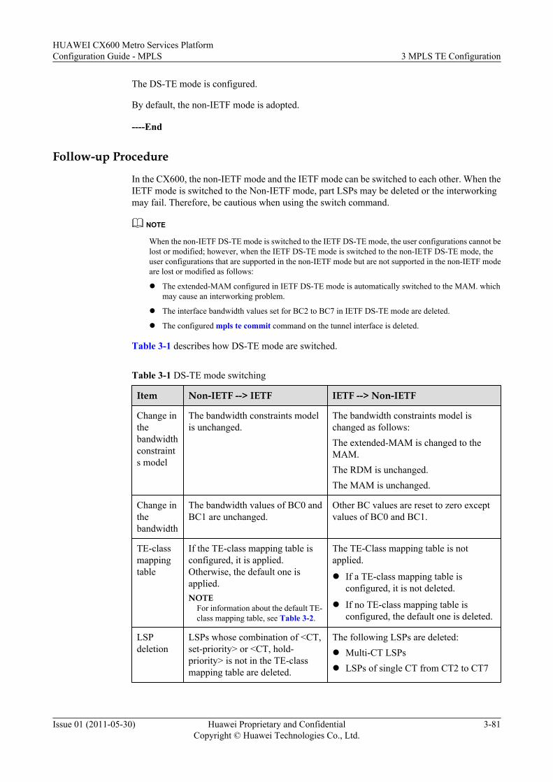
The DS-TE mode is configured.
By default, the non-IETF mode is adopted.
----End
Follow-up Procedure
In the CX600, the non-IETF mode and the IETF mode can be switched to each other. When theIETF mode is switched to the Non-IETF mode, part LSPs may be deleted or the interworkingmay fail. Therefore, be cautious when using the switch command.
NOTE
When the non-IETF DS-TE mode is switched to the IETF DS-TE mode, the user configurations cannot belost or modified; however, when the IETF DS-TE mode is switched to the non-IETF DS-TE mode, theuser configurations that are supported in the non-IETF mode but are not supported in the non-IETF modeare lost or modified as follows:
l The extended-MAM configured in IETF DS-TE mode is automatically switched to the MAM. whichmay cause an interworking problem.
l The interface bandwidth values set for BC2 to BC7 in IETF DS-TE mode are deleted.
l The configured mpls te commit command on the tunnel interface is deleted.
Table 3-1 describes how DS-TE mode are switched.
Table 3-1 DS-TE mode switching
Item Non-IETF --> IETF IETF --> Non-IETF
Change inthebandwidthconstraints model
The bandwidth constraints modelis unchanged.
The bandwidth constraints model ischanged as follows:The extended-MAM is changed to theMAM.The RDM is unchanged.The MAM is unchanged.
Change inthebandwidth
The bandwidth values of BC0 andBC1 are unchanged.
Other BC values are reset to zero exceptvalues of BC0 and BC1.
TE-classmappingtable
If the TE-class mapping table isconfigured, it is applied.Otherwise, the default one isapplied.NOTE
For information about the default TE-class mapping table, see Table 3-2.
The TE-Class mapping table is notapplied.
l If a TE-class mapping table isconfigured, it is not deleted.
l If no TE-class mapping table isconfigured, the default one is deleted.
LSPdeletion
LSPs whose combination of <CT,set-priority> or <CT, hold-priority> is not in the TE-classmapping table are deleted.
The following LSPs are deleted:l Multi-CT LSPsl LSPs of single CT from CT2 to CT7
HUAWEI CX600 Metro Services PlatformConfiguration Guide - MPLS 3 MPLS TE Configuration
Issue 01 (2011-05-30) Huawei Proprietary and ConfidentialCopyright © Huawei Technologies Co., Ltd.
3-81
3.14.3 Configuring DS-TE Bandwidth Constraints ModelIf preemption for CT bandwidth is enabled, you are recommended to adopt the RDM, whicheffectively uses bandwidth. If preemption for CT bandwidth is disabled on a network, you arerecommended to adopt the MAM or the extended-MAM.
ContextDo as follows on each LSR in a DS-TE domain:
Procedure
Step 1 Run:system-view
The system view is displayed.
Step 2 Run:mpls
The MPLS view is displayed.
Step 3 Run:mpls te ds-te bcm { extend-mam | mam | rdm }
The DS-TE bandwidth constraints model is configured.
By default, the DS-TE bandwidth constraints model is the RDM.
The DS-TE non-IETF mode does not support the extended-MAM.
----End
3.14.4 (Optional) Configuring TE-Class Mapping TableYou are recommended to configure the same TE class mapping table in an entire DS-TE domain.Otherwise, LSPs may be incorrectly set up.
ContextThis configuration procedure is unnecessary to the non-IETF DS-TE.
For IETF DS-TE, it is recommended that the TE-class mapping tables applied to the entire DS-TE domain are the same. Otherwise, Some LSPs may not be set up correctly.
Do as follows on each LSR of a DS-TE domain in DS-TE IETF mode:
Procedure
Step 1 Run:system-view
The system view is displayed.
Step 2 Run:te-class-mapping
3 MPLS TE ConfigurationHUAWEI CX600 Metro Services Platform
Configuration Guide - MPLS
3-82 Huawei Proprietary and ConfidentialCopyright © Huawei Technologies Co., Ltd.
Issue 01 (2011-05-30)
A TE-class mapping table is configured and the TE-Class mapping table view is displayed.
Step 3 Run one or multiple commands as follows to configured TE-Classes:
l To configure TE-Class0, run:te-class 0 class-type { ct0 | ct1 | ct2 | ct3 | ct4 | ct5 | ct6 | ct7 } priority priority [ description description-info ]
l To configure TE-Class1, run:te-class 1 class-type { ct0 | ct1 | ct2 | ct3 | ct4 | ct5 | ct6 | ct7 } priority priority [ description description-info ]
l To configure TE-Class2, run:te-class 2 class-type { ct0 | ct1 | ct2 | ct3 | ct4 | ct5 | ct6 | ct7 } priority priority [ description description-info ]
l To configure TE-Class3, run:te-class 3 class-type { ct0 | ct1 | ct2 | ct3 | ct4 | ct5 | ct6 | ct7 } priority priority [ description description-info ]
l To configure TE-Class4, run:te-class 4 class-type { ct0 | ct1 | ct2 | ct3 | ct4 | ct5 | ct6 | ct7 } priority priority [ description description-info ]
l To configure TE-Class5, run:te-class 5 class-type { ct0 | ct1 | ct2 | ct3 | ct4 | ct5 | ct6 | ct7 } priority priority [ description description-info ]
l To configure TE-Class6, run:te-class 6 class-type { ct0 | ct1 | ct2 | ct3 | ct4 | ct5 | ct6 | ct7 } priority priority [ description description-info ]
l To configure TE-Class7, run:te-class 7 class-type { ct0 | ct1 | ct2 | ct3 | ct4 | ct5 | ct6 | ct7 } priority priority [ description description-info ]
When configuring a TE-class mapping table, pay attention to the following information:
l Each DS-TE node has one TE-class mapping table at most.
l TE-class is a global concept, that is , TE-class is applied to all DS-TE tunnels of the LSR.
l A TE-class indicates the combination of a Class-Type (CT) and priority. The priorityindicates the priority for CR-LSP preemption rather than the value of the EXP field in theMPLS packet header. The value of the preemption priority ranges from 0 to 7. The smallerthe value is, the higher the priority is. A CR-LSP can be set up only when both the combinationof its CT and setup priority (<CT, setup-priority>) and the combination of its CT and holdingpriority (<CT, hold-priority>) exist in the TE-class mapping table. For example, suppose theTE-class mapping table of a certain node contains only TE-Class[0] = <CT0, 6> and TE-Class[1] = <CT0, 7>. Only the following types of CR-LSPs can be set up successfully:
– Class-Type = CT0, setup-priority = 6, hold-priority = 6
– Class-Type = CT0, setup-priority = 7, hold-priority = 6
– Class-Type = CT0, setup-priority = 7, hold-priority = 7
NOTEThe setup-priority cannot be higher than the hold-priority. Therefore, the LSP , whose Class-Type isCT0, setup-priority is 6, holding priority is 7, does not exist.
l In the MAM and extended-MAM, the CT of a higher priority can preempt the bandwidth ofCTs of the same type. CTs of different types do not preempt the bandwidth of each other.
l In the RDM, the preemption of bandwidth among CTs is determined by the preemptionpriority and the corresponding bandwidth constraint. Assume m and n are preemptionpriorities (0<=m<n<=7) and i and j are CT values (0<=i<j<=7).
HUAWEI CX600 Metro Services PlatformConfiguration Guide - MPLS 3 MPLS TE Configuration
Issue 01 (2011-05-30) Huawei Proprietary and ConfidentialCopyright © Huawei Technologies Co., Ltd.
3-83
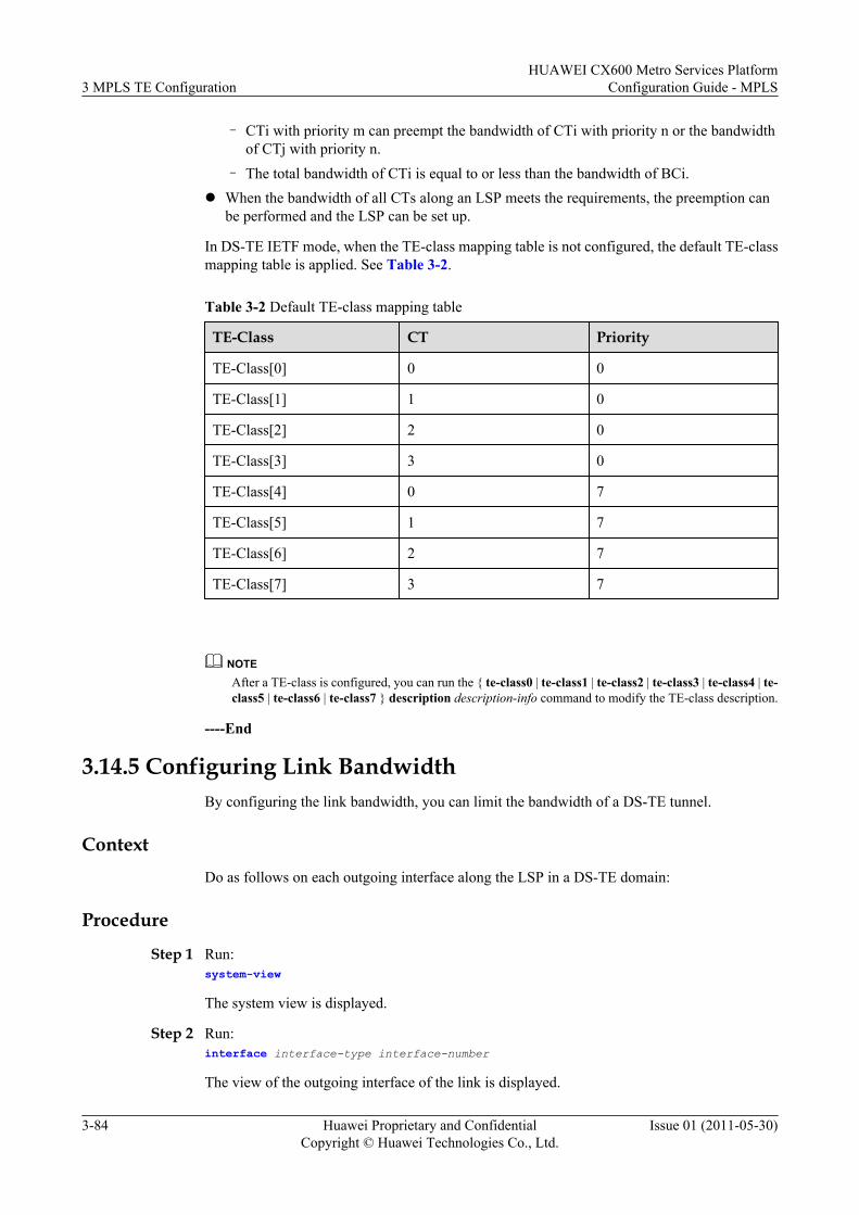
– CTi with priority m can preempt the bandwidth of CTi with priority n or the bandwidthof CTj with priority n.
– The total bandwidth of CTi is equal to or less than the bandwidth of BCi.l When the bandwidth of all CTs along an LSP meets the requirements, the preemption can
be performed and the LSP can be set up.
In DS-TE IETF mode, when the TE-class mapping table is not configured, the default TE-classmapping table is applied. See Table 3-2.
Table 3-2 Default TE-class mapping table
TE-Class CT Priority
TE-Class[0] 0 0
TE-Class[1] 1 0
TE-Class[2] 2 0
TE-Class[3] 3 0
TE-Class[4] 0 7
TE-Class[5] 1 7
TE-Class[6] 2 7
TE-Class[7] 3 7
NOTEAfter a TE-class is configured, you can run the { te-class0 | te-class1 | te-class2 | te-class3 | te-class4 | te-class5 | te-class6 | te-class7 } description description-info command to modify the TE-class description.
----End
3.14.5 Configuring Link BandwidthBy configuring the link bandwidth, you can limit the bandwidth of a DS-TE tunnel.
ContextDo as follows on each outgoing interface along the LSP in a DS-TE domain:
Procedure
Step 1 Run:system-view
The system view is displayed.
Step 2 Run:interface interface-type interface-number
The view of the outgoing interface of the link is displayed.
3 MPLS TE ConfigurationHUAWEI CX600 Metro Services Platform
Configuration Guide - MPLS
3-84 Huawei Proprietary and ConfidentialCopyright © Huawei Technologies Co., Ltd.
Issue 01 (2011-05-30)
Step 3 Run:mpls te bandwidth max-reservable-bandwidth bw-value
The maximum reservable bandwidth of the link is configured.
Step 4 Run:mpls te bandwidth { bc0 bc0-bw-value | bc1 bc1-bw-value | bc2 bc2-bw-value | bc3 bc3-bw-value | bc4 bc4-bw-value | bc5 bc5-bw-value | bc6 bc6-bw-value | bc7 bc7-bw-value }*
The BC bandwidth of the link is configured.
----End
Follow-up ProcedureIn different bandwidth constraints models, the relationships between the reservable bandwidthand the bandwidth of each BC are different.
l In the RDM: max-reservable-bandwidth >= bc0-bw-value >= bc1-bw-value >= bc2-bw-value >= bc3-bw-value >= bc4-bw-value >= bc5-bw-value >= bc6-bw-value >= bc7-bw-value
l In the MAM: max-reservable-bandwidth >= bc0-bw-value + bc1-bw-value + bc2-bw-value + bc3-bw-value + bc4-bw-value + bc5-bw-value + bc6-bw-value + bc7-bw-value
l In the extended-MAM: It is the same as the MAM.
BC is the bandwidth constraint for outgoing interface, while CT bandwidth is the bandwidth ofthe class type of DS-TE tunnel. The total bandwidth of BCi (0 <= i <= 7) of an interface is equalto or greater than the CTi bandwidth of all tunnels passing through this outgoing interface. Forexample, three LSPs of CT1 pass through a link and their bandwidth values are x, y, and zrespectively. The bandwidth of BC1 of the link should be equal to or greater than the totalbandwidth of x, y, and z.
3.14.6 Configuring the Tunnel InterfaceTo set up a DS-TE tunnel, you must create a tunnel interface and configure other tunnel attributeson the tunnel interface.
ContextDo as follows on the ingress of a TE tunnel:
Procedure
Step 1 Run:system-view
The system view is displayed.
Step 2 Run:interface tunnel interface-number
The tunnel interface is created and the tunnel interface view is displayed.
Step 3 (Optional) Run:description text
HUAWEI CX600 Metro Services PlatformConfiguration Guide - MPLS 3 MPLS TE Configuration
Issue 01 (2011-05-30) Huawei Proprietary and ConfidentialCopyright © Huawei Technologies Co., Ltd.
3-85
The tunnel description information is configured.
Step 4 Run one of the following commands to configure the IP address of the tunnel interface.
l ip address ip-address { mask | mask-length } [ sub ]
The IP address of the tunnel interface is configured.
The secondary IP address can be configured on the tunnel interface only when the primaryIP address is configured. ip_address_unnumbered
l ip address unnumbered interface interface-type interface-number
The tunnel interface borrows the IP address of another interface.
To forward traffic, the tunnel interface must be configured with an IP address. Because that anMPLS TE tunnel is unidirectional, no peer address exists. Therefore, a tunnel interface needsnot to be assigned with an IP address. Instead, the tunnel interface takes the LSR ID of the localnode as its IP address.
Step 5 Run:tunnel-protocol mpls te
MPLS TE is configured as the tunnel protocol.
Step 6 Run:destination ip-address
The LSR ID of the egress is configured as the destination address of the tunnel.
By default, the tunnel is a GRE tunnel. Different tunnels require different destination addresses.When the tunnel protocol is changed from another protocol to MPLS TE, the precedingdestination address is deleted and a new one needs to be configured.
Step 7 Run:mpls te tunnel-id tunnel-id
The tunnel ID is configured.
Step 8 Run:mpls te signal-protocol { cr-static | rsvp-te }
The signaling protocol of the tunnel is configured.
Step 9 (Optional) run:mpls te priority setup-priority [ hold-priority ]
The priority for the tunnel is configured.
By default, both the setup-priority and the hold-priority are 7. Both the setup-priority and thehold-priority range from 0 to 7. The smaller the value is, the higher the priority is.
NOTEThe setup priority should not be higher than the holding priority. When the holding priority is not specified,it is the same as the setup priority.
Step 10 Run:mpls te commit
The configuration of the tunnel is committed.
3 MPLS TE ConfigurationHUAWEI CX600 Metro Services Platform
Configuration Guide - MPLS
3-86 Huawei Proprietary and ConfidentialCopyright © Huawei Technologies Co., Ltd.
Issue 01 (2011-05-30)
When the MPLS TE parameters are modified each time, you need to run the mpls te commitcommand to commit the configuration.
----End
3.14.7 Configuring the Static CR-LSP and the BandwidthA static CR-LSP supports eight CTs in standard DS-TE mode and supports CT0 and CT1 innon-standard DS-TE mode.
Procedurel Configure the ingress of the static CR-LSP.
Do as follows on the ingress of the static CR-LSP:
1. Run:system-view
The system view is displayed.2. Run:
static-cr-lsp ingress { tunnel-interface tunnel interface-number | tunnel-name } destination destination-address { nexthop next-hop-address | outgoing-interface interface-type interface-number } out-label out-label bandwidth { ct0 | ct1 | ct2 | ct3 | ct4 | ct5 | ct6 | ct7 } bandwidth
The ingress of the static CR-LSP is configured and its CT and the bandwidth arespecified.
NOTE
l tunnel interface-number is the interface number of the MPLS TE tunnel of the static CR-LSP.
l The static CR-LSP supports eight CTs in DS-TE IETF mode and supports only CT0 andCT1 in DS-TE non-IETF mode. That is, the CT of the static CR-LSP in IETF mode can bewhichever of the CT0 to CT7; the static CR-LSP in non-IETF mode can only be CT0 orCT1.
l The tunnel bandwidth cannot exceed the max-reservable bandwidth of the link.
l tunnel-name must be the same as that in the interface tunnel tunnel-number command.The value is a case-sensitive string without blank space or abbreviation. Assume a tunnelinterface is created through the interface tunnel 2/0/0 command. The tunnel name isTunnel 2/0/0 and the parameter of the ingress of the static CR-LSP must be Tunnel 2/0/0.Otherwise, the tunnel is set up incorrectly. This rule is inapplicable to transit LSRs or theegress.
The static CR-LSP supports the single CT only in DS-TE IETF mode. The static CR-LSPhas the highest priority whose value is zero, and does not support bandwidth preemption.That is, when a static CR-LSP is being set up, it does not preempt the resources of otherLSPs regardless whether the unreserved bandwidth of its out interface is enough or not. Inaddition, after a static CR-LSP is set up, its bandwidth cannot be preempted by other LSPs.
On one node (ingress, transit LSR, or egress) in any Bandwidth Constraints model, the totalbandwidth of CTi is not more than the bandwidth of BCi (0 <= i <= 7). That is, CTi canuse only bandwidth of BCi.
For instance, the bandwidth of BC1 on PE is x. Two static CR-LSPs with the CT1 bandwidthbeing y and z respectively are set up on the PE. The total bandwidth of CT1s (y + z) is notmore than the bandwidth of BC1 (x).
HUAWEI CX600 Metro Services PlatformConfiguration Guide - MPLS 3 MPLS TE Configuration
Issue 01 (2011-05-30) Huawei Proprietary and ConfidentialCopyright © Huawei Technologies Co., Ltd.
3-87
NOTEIf the bandwidth of the MPLS TE tunnel is configured more than 28630 kbit/s, the actual bandwidthallocation on the MPLS TE tunnel may be not precise. The MPLS TE tunnel, however, can be setup successfully.
l Configure the transit LSR of the static CR-LSP.
The configuration is unnecessary if the static CR-LSP has only the ingress and egress. Whentransit LSRs reside in the static CR-LSP, do as follows on each transit LSR:
1. Run:system-view
The system view is displayed.2. Run:
static-cr-lsp transit lsp-name incoming-interface interface-type interface-number in-label in-label-value { nexthop next-hop-address | outgoing-interface interface-type interface-number } out-label out-label-value bandwidth { ct0 | ct1 | ct2 | ct3 | ct4 | ct5 | ct6 | ct7 } bandwidth
The transit LSR of the static CR-LSP is configured.
On the transit LSR and egress, tunnel-name cannot be specified as the same as thename of an existing tunnel on the node. The name of the MPLS TE tunnel interfaceassociated with the static CR-LSP can be used, such as Tunnel1/0/0.
l Configure the egress of the static CR-LSP.
Do as follows on the egress of the static CR-LSP:
1. Run:system-view
The system view is displayed.2. Run:
static-cr-lsp egress lsp-name incoming-interface interface-type interface-number in-label in-label [ lsrid ingress-lsr-id tunnel-id tunnel-id ]
The egress of the static CR-LSP is configured.
----End
3.14.8 Configuring the RSVP CR-LSP and Its BandwidthWhen establishing an RSVP CR-LSP and specifying the bandwidth, you need to ensure that thebandwidth of LSPs of all CTs is not greater than the bandwidth of all BCs.
Procedurel Configuring IGP-TE
For detailed configurations, see the section Configuring OSPF TE or Configuring IS-ISTE.
l Configuring CSPF
For detailed configurations, see the section Configuring CSPF.l Configure the bandwidth of the MPLS TE tunnel
Do as follows on the ingress of an MPLS TE tunnel:
3 MPLS TE ConfigurationHUAWEI CX600 Metro Services Platform
Configuration Guide - MPLS
3-88 Huawei Proprietary and ConfidentialCopyright © Huawei Technologies Co., Ltd.
Issue 01 (2011-05-30)
1. Run:system-view
The system view is displayed.2. Run:
interface tunnel interface-number
The MPLS TE tunnel interface view is displayed.3. Run one of the following commands to configure the bandwidth of the MPLS TE
tunnel interface.
– To configure the single CT, run:mpls te bandwidth { ct0 bw-value [ flow-queue ] | ct1 bw-value [ flow-queue ] | ct2 bw-value | ct3 bw-value | ct4 bw-value | ct5 bw-value | ct6 bw-value | ct7 bw-value }
NOTE
l If you specify the name of the flow queue template referenced by the tunnel in thiscommand, traffic over the tunnel is then scheduled and assigned bandwidth based onthe flow queue template.
l If the flow queue template referenced by the tunnel is not specified, the systemautomatically generates the flow queue template referenced by the tunnel according tothe CT and flow queue mapping configured in the ct-flow-mapping view.
– To configure the multi-CT, runmpls te bandwidth { ct0 bw-value | ct1 bw-value | ct2 bw-value | ct3 bw-value | ct4 bw-value | ct5 bw-value | ct6 bw-value | ct7 bw-value } *
NOTE
If the flow queue template needs to be referenced when the single CT is configured, configurethe flow queue template first. For detailed configurations of the flow queue template, refer tothe HUAWEI CX600 Metro Services Platform Configuration Guide - QoS.In tunnel policy, the multiple class type (multi-CT) CR-LSP supports only the VPN tunnelbinding mode rather than the select-sequence mode.
4. Run:mpls te commit
The current configuration of the tunnel is committed.
On one node in any the Bandwidth Constraints model, the total bandwidth of CTi is notmore than the bandwidth of BCi (0 <= i <= 7) irrespective of. That is, CTi can use only thebandwidth of BCi.
For instance, the bandwidth of BC1 on a PE is x and two CR-LSPs are set up on the nodewith their CT1 bandwidth being y and z respectively. The total bandwidth of CT1 (y + z)is not more than the bandwidth of BC1 (x).
NOTEIf the bandwidth of the MPLS TE tunnel is configured as more than 28630 kbit/s, the bandwidthallocation on the MPLS TE tunnel may be not precise. The MPLS TE tunnel, however, can be setup successfully.
l (Optional) Configure the explicit path of the tunnel.
To specify the path used by the tunnel, do as follows on the ingress of the tunnel:
1. Create and configure the explicit path. See Configuring MPLS-TE Explicit Path.2. Run:
quit
HUAWEI CX600 Metro Services PlatformConfiguration Guide - MPLS 3 MPLS TE Configuration
Issue 01 (2011-05-30) Huawei Proprietary and ConfidentialCopyright © Huawei Technologies Co., Ltd.
3-89
Return to the system view.3. Run:
interface tunnel interface-number
The MPLS TE tunnel interface view is displayed.4. Run:
mpls te path explicit-path path-name
The explicit path used by the tunnel is configured.5. Run:
mpls te commit
The current configuration of the tunnel is committed.
----End
3.14.9 Configuring Mappings Between CTs and Flow Queues
ContextDo as follows on the ingress of a DS-TE tunnel:
Procedure
Step 1 Run:system-view
The system view is displayed.
Step 2 Run:ct-flow-mapping template name
The template of mappings between CTs and flow queues is created and the ct-flow-mappingview is displayed.
Step 3 Run:map ct ct-number to { cs7 | cs6 | ef | af4 | af3 | af2 | af1 | be } [ pq | wfq | lpq ]
The mappings between CTs and flow queues are configured.
3 MPLS TE ConfigurationHUAWEI CX600 Metro Services Platform
Configuration Guide - MPLS
3-90 Huawei Proprietary and ConfidentialCopyright © Huawei Technologies Co., Ltd.
Issue 01 (2011-05-30)
NOTE
l Support flexible mapping between CTs and flow queues.
l The system supports eight templates of the mappings between CTs and flow queues. Seven templates canbe manually configured; one template is default and you cannot modify the configuration of this defaulttemplate.
l By default, the default template is adopted. The default template defines the mappings between CTs andflow queues as follows:
l Maps CT 0 to be lpq.
l Maps CT 1 to af1 wfq.
l Maps CT 2 to af2 wfq.
l Maps CT 3 to af3 wfq.
l Maps CT 4 to af4 wfq.
l Maps CT 5 to ef pq.
l Maps CT 6 to cs6 pq.
l Maps CT 7 to cs7 pq.
l According to the parameters of a flow queue configured through the map ct ct-number to { cs7 | cs6 | ef |af4 | af3 | af2 | af1 | be } [ pq | wfq | lpq ] command, the system automatically generates a template applicableto the DS-TE tunnel.
Step 4 Run:ct-flow-mapping commit
The mappings between CTs and flow queues defined in the template are committed. Thus, themappings can take effect.
Step 5 Run:quit
Return to the system view from the ct-flow-mapping view.
Step 6 Run:interface interface-type interface-number
The interface view is displayed.
NOTE
The interface is the physical interface that is bound to the DS-TE tunnel on the ingress.
Step 7 Run:mpls te ct-flow-mapping mapping-name
The template of mappings between CTs and flow queues is applied to the interface.
Step 8 (Optional) Run:mpls te ct-bandwidth unshared
The interface enabled with DS-TE is configured that CTs do not share the bandwidth of eachother.
HUAWEI CX600 Metro Services PlatformConfiguration Guide - MPLS 3 MPLS TE Configuration
Issue 01 (2011-05-30) Huawei Proprietary and ConfidentialCopyright © Huawei Technologies Co., Ltd.
3-91
NOTE
l When the interface enabled with DS-TE is configured to share bandwidths of CTs, it indicates that eightCTs of a DS-TE tunnel can share the bandwidth of each other. In this manner, the bandwidth of the DS-TEtunnel is efficiently used. Thus, it is recommended you to adopt the shared attribute by default.
l When CTs can share the bandwidth of each other on the interface enabled with DS-TE, the shaping parameterof the flow queue parameters is the CIR of SQ, that is, the total bandwidths of CTs.
l When CTs cannot share the bandwidth of each other on the interface enabled with DS-TE, the shapingparameter of the flow queue parameters is the bandwidth of the CT.
l When an interface supports DS-TE and is selected as the outgoing interface of a tunnel working in Up state,you need to reset the tunnel to take the modification of the shared or unshared attribute on the interface intoeffect.
----End
3.14.10 (Optional) Configuring the Interface Class Queue
ContextDo as follows on the interface at the network side on the ingress of a DS-TE tunnel:
NOTE
l The interface class queue is an interface-specific scheduling policy. You can configure according to thenetwork scheme.
l It is recommended that traffic of the same service type applies the same queue scheduling mode to the flowqueue and the class queue.
Procedure
Step 1 Run:system-view
The system view is displayed.
Step 2 Run:port-wred port-wred-name
A port WRED object is created and the port WRED view is displayed.
Step 3 Run:color { green | yellow | red } low-limit low-limit-value high-limit high-limit-value discard-percentage discard-percentage-value
A WRED object for a class queue is configured and the upper limit, the lower limit, and thediscard probability are set for packets of different colors.
NOTE
l If you do not configure a WRED object for a class queue, the system uses the default tail-drop policy.
l You can create multiple port-wred objects to be referenced by class queues as required. The systemprovides one default port-wred object. In addition, you can configure a maximum of seven port-wredobjects.
Step 4 Run:quit
You return to the system view.
3 MPLS TE ConfigurationHUAWEI CX600 Metro Services Platform
Configuration Guide - MPLS
3-92 Huawei Proprietary and ConfidentialCopyright © Huawei Technologies Co., Ltd.
Issue 01 (2011-05-30)
Step 5 Run:interface interface-type interface-number
The interface view is displayed.
Step 6 Run:port-queue cos-value { { pq | wfq weight weight-value | lpq} | shaping { shaping-value | shaping-percentage shaping-percentage-value } | port-wred wred-name } * outbound
A class queue is configured and a scheduling policy is set for queues of different priorities.
You can configure scheduling parameters for eight class queues on one interface.
If you do not configure a class queue template, the system uses the default class queue template.The default class queue template contains the following parameters:
l By default, the system performs PQ on the class queues ef, cs6, and cs7.l The system performs WFQ on the class queues be, af1, af2, af3, and af4. The scheduling
weight is 10:10:10:15:15.l The default shaping value is the maximum bandwidth of the interface.l The default discard policy is tail drop.
----End
3.14.11 Checking the ConfigurationAfter a DS-TE tunnel is configured, you can view information about DS-TE and traffic of eachCT on the tunnel interface.
PrerequisiteThe configurations of the DS-TE tunnel function are complete.
Procedurel Run the display mpls te ds-te { summary | te-class-mapping [ default | config |
verbose ] } command to check information about DS-TE.l Run display mpls te te-class-tunnel { all | { ct0 | ct1 | ct2 | ct3 | ct4 | ct5 | ct6 | ct7 }
priority priority } command to check TE tunnels associated with the TE-classes.l Run the display interface tunnel interface-number command to check information about
traffic of each CT on the tunnel interface.
NOTE
Before viewing traffic information about each CT configured for a DS-TE tunnel, run the mpls telsp-tp outbound command in the tunnel interface view to limit the rate at which TE traffic istransmitted.
----End
ExampleAfter the configuration, run the following commands, and you can view the information.
l Run the display mpls te ds-te command on the ingress of the tunnel, and you can viewinformation about DS-TE.
HUAWEI CX600 Metro Services PlatformConfiguration Guide - MPLS 3 MPLS TE Configuration
Issue 01 (2011-05-30) Huawei Proprietary and ConfidentialCopyright © Huawei Technologies Co., Ltd.
3-93
l Run the display mpls te te-class-tunnel command on the ingress of the tunnel, and youcan view TE tunnels associated with the TE-classes.
l Run the display interface tunnel interface-number command on the ingress of the tunnel,and you can view information about traffic of each CT on the tunnel.
3.15 Configuring MPLS TE FRRMPLS TE FRR is a local protection technique and is used to protect a CR-LSP against link faultsand node faults. MPLS TE FRR needs to be configured manually.
3.15.1 Establishing the Configuration TaskBefore configuring MPLS TE FRR, familiarize yourself with the applicable environment,complete the pre-configuration tasks, and obtain the required data. This can help you completethe configuration task quickly and accurately.
3.15.2 Enabling TE Fast RerouteBefore configuring manual TE FRR, you must enable TE FRR.
3.15.3 Configuring Bypass TunnelsTo configure MPLS TE FRR, you need to configure a path and the attributes for a bypass tunnel.
3.15.4 (Optional) Configuring the Scanning Timer for FRRBy configuring a TE FRR scanning timer, you can search for the eligible LSPs that can functionas bypass LSPs and then bind the optimal LSP to the primary LSP.
3.15.5 (Optional) Modifying PSB and RSB Timeout MultiplierTo perform TE FRR during the RSVP GR process, you need to modify the timeout multiplierof the PSB or RSB.
3.15.6 Checking the ConfigurationAfter the configuration of MPLS TE FRR, you can view detailed information about a bypasstunnel.
3.15.1 Establishing the Configuration TaskBefore configuring MPLS TE FRR, familiarize yourself with the applicable environment,complete the pre-configuration tasks, and obtain the required data. This can help you completethe configuration task quickly and accurately.
Applicable EnvironmentMPLS TE Fast ReRoute (FRR) is a local protection technique.
NOTE
The RSVP-TE tunnel of SE style supports FRR; the static TE tunnel does not support FRR.
Additional bandwidth is occupied because the bypass tunnel used by the FRR needs to be pre-established. When idle network bandwidth is insufficient, the FRR should be used only forimportant nodes or links.
l Supporting board hot pulling-out protectionWhen the interface board where an outgoing interface of a primary tunnel on a PLR residesis pulled out, the MPLS TE traffic is swiftly switched to the bypass tunnel. When theinterface board is re-inserted and the outgoing interface of the primary tunnel is available,MPLS TE traffic is switched back to the primary tunnel. The TE FRR with board hot
3 MPLS TE ConfigurationHUAWEI CX600 Metro Services Platform
Configuration Guide - MPLS
3-94 Huawei Proprietary and ConfidentialCopyright © Huawei Technologies Co., Ltd.
Issue 01 (2011-05-30)
pulling-out protection is used to protect the outgoing interface of the primary tunnel on aPLR.
When board hot pulling-out protection is used, note that the tunnel interface of the primarytunnel on a PLR, the tunnel interface of the bypass tunnel, and the outgoing interface ofthe bypass tunnel must not reside on the interface board to be pulled out. It is recommendedto configure the TE tunnel interfaces of a PLR on the main control board.
NOTE
When the interface where the LSP or CR-LSP resides is deleted, or when the board where the interfaceresides is pulled out, the interface goes to the Stale state and becomes a staled interface. If the numberof staled interfaces on a node reaches the maximum specified in the license, the node cannot provideFRR protection for the primary tunnel in the following cases:
l The undo mpls command is run on the outgoing interface of the primary tunnel.
l The interface board where the outgoing interface of the primary tunnel resides is pulled out orthe interface board fails.
l Supporting FRR during RSVP GR
In the CX600, the FRR can be performed to reduce the fault duration when the PLR node,PLR upstream node, MP, or MP downstream node is restarted or the switchover isperformed; meanwhile, the outgoing interface of the primary tunnel of the PLR fails.
During the RSVP GR, the Down event of the outgoing interface on the tunnel triggers FRRswitchover.
l Not supporting simultaneous failure of multiple nodes
The FRR does not take effect when multiple nodes fail simultaneously. That is, if the FRRis performed, data is switched from the primary LSP to the bypass LSP. During the periodthat data is transmitted on the bypass LSP, the bypass LSP must be in the Up state all thetime. If the bypass LSP goes Down during this period, the protected data cannot beforwarded through MPLS. Data transmission then is interrupted and the FRR function isinvalidated. Although the bypass LSP goes Up again, it cannot forward data. Data can beforwarded only after the primary LSP is restored or re-created.
When configuring a bypass LSP, you must specify the link or node protected by the bypass LSPand ensure that this bypass LSP does not pass through the link or node it protects. Otherwise,the protection does not take effect.
Pre-configuration Tasks
Before configuring MPLS TE fast reroute, complete the following tasks:
l Establishing the primary LSP by using the RSVP-TE signaling protocol
l Enabling MPLS TE and RSVP TE in the MPLS view and physical interface view of thenode along the bypass tunnel (See Enabling MPLS TE and RSVP TE.)
l (Optional) Configuring physical bandwidth of the bypass tunnel (See (Optional)Configuring Link Bandwidth.)
l Enabling CSPF on the PLR node
l (Optional) Configuring the explicit path of the bypass tunnel
Data Preparation
To configure TE FRR, you need the following data.
HUAWEI CX600 Metro Services PlatformConfiguration Guide - MPLS 3 MPLS TE Configuration
Issue 01 (2011-05-30) Huawei Proprietary and ConfidentialCopyright © Huawei Technologies Co., Ltd.
3-95
No. Data
1 Protection policy of FRR, that is, a node or a link that is the object to be protected
2 (Optional) Bandwidth of the bypass tunnel
3 (Optional) Scanning interval of TE FRR
3.15.2 Enabling TE Fast RerouteBefore configuring manual TE FRR, you must enable TE FRR.
ContextBy default, the TE FRR is disabled.
Do as follows on the ingress node along the primary LSP:
ProcedureStep 1 Run:
system-view
The system view is displayed.
Step 2 Run:interface tunnel interface-number
The tunnel interface view of the primary LSP is displayed.
Step 3 Run:mpls te fast-reroute [ bandwidth ]
FRR is enabled.
NOTE
The primary tunnel in a tunnel protection group can be configured with the TE FRR for dual protection.On the ingress, the tunnel protection group and TE FRR cannot be configured together. Otherwise, neitherthe tunnel protection group nor TE FRR takes effect. The protection tunnel in the tunnel protection group,however, cannot be configured with the TE FRR.For example, assume Tunnel 1/0/0 and Tunnel 2/0/0 are MPLS TE tunnel interfaces and the ID of Tunnel2/0/0 is 200. The mpls te protection tunnel 200 and mpls te fast-reroute commands can be run on Tunnel1/0/0. That is, Tunnel 1/0/0 can be the primary tunnel in the protection group and the TE FRR function.When the mpls te protection tunnel 200 command is run on Tunnel 1/0/0, the mpls te fast-reroutecommand cannot be run on Tunnel 2/0/0.
Step 4 Run:mpls te commit
The current tunnel configuration is committed.
----End
3.15.3 Configuring Bypass TunnelsTo configure MPLS TE FRR, you need to configure a path and the attributes for a bypass tunnel.
3 MPLS TE ConfigurationHUAWEI CX600 Metro Services Platform
Configuration Guide - MPLS
3-96 Huawei Proprietary and ConfidentialCopyright © Huawei Technologies Co., Ltd.
Issue 01 (2011-05-30)
ContextDo as follows on the PLR node:
Procedure
Step 1 Run:system-view
The system view is displayed.
Step 2 Run:interface tunnel interface-number
The interface view of the MPLS TE tunnel is displayed.
Step 3 To configure the IP address for the bypass tunnel interface, run the following commands asrequired.l Run:
ip address ip-address { mask | mask-length } [ sub ]
The IP address of the bypass tunnel interface is configured.The secondary IP address of the interface can be configured only after the primary IP addressis configured.
l Run:ip address unnumbered interface
The bypass tunnel interface borrows an IP address from another interface.
NOTE
To forward traffic, the tunnel interface must be configured with an IP address. An MPLS TE tunnel isunidirectional and no peer address exists. Therefore, a tunnel interface needs not to be assigned withan IP address. The tunnel interface borrows the loopback interface address that is used as the LSR IDof the local node.
Step 4 Run:tunnel-protocol mpls te
MPLS TE is specified as the tunneling protocol.
Step 5 Run:destination ip-address
The destination address of the bypass tunnel is configured as the LSR ID of the MP node.
Step 6 Run:mpls te tunnel-id tunnel-id
The ID of the bypass tunnel is configured.
Step 7 (Optional) Run:mpls te path explicit-path path-name
The explicit path used by the bypass tunnel is configured.
The physical link that the bypass tunnel passes through cannot overlap through which the primarytunnel passes.
HUAWEI CX600 Metro Services PlatformConfiguration Guide - MPLS 3 MPLS TE Configuration
Issue 01 (2011-05-30) Huawei Proprietary and ConfidentialCopyright © Huawei Technologies Co., Ltd.
3-97
Step 8 (Optional) Run either of the following commands as required:l mpls te bandwidth { ct0 ct0-bw-value | ct1 ct0-bw-value } [ flow-queue flow-
queue ]
l mpls te bandwidth { { ct0 ct0-bw-value | ct1 ct1-bw-value | ct2 ct2-bw-value | ct3 ct3-bw-value | ct4 ct4-bw-value | ct5 ct5-bw-value | ct6 ct6-bw-value | ct7 ct7-bw-value } *
The bandwidth of the bypass tunnel is set.
Step 9 Run:mpls te bypass-tunnel
The bypass tunnel are configured.
NOTE
One tunnel interface cannot serve as the bypass tunnel and backup tunnel at the same time, nor as the bypasstunnel and the protect tunnel in a protection group. That is, the mpls te bypass-tunnel and mpls tebackup commands cannot be configured on the same interface, and the mpls te bypass-tunnel and mplste protection tunnel commands also cannot be configured on the same interface.
Step 10 Run:mpls te protected-interface interface-type interface-number
The interface to be protected by the bypass tunnel is specified.
NOTE
The mpls te protected-interface and mpls te backup commands cannot be run on the same tunnel interfaceat the same time.
Step 11 Run:mpls te commit
The current tunnel configuration is committed.
----End
Follow-up ProcedureAfter the bypass tunnel is configured, the route record is enabled.
One bypass tunnel protects up to three physical interfaces. After a tunnel is specified to protecta physical interface, its corresponding LSP becomes the bypass LSP. The establishment of abypass LSP can be triggered when an explicit path on the PLR is configured.
During the FRR period, if the bypass LSP goes Down, the protected data cannot be forwardedover an MPLS network; thus traffic may be interrupted and the FRR fails. Even after the bypassLSP goes Up again, traffic cannot be forwarded. Traffic can be forwarded only after the primaryLSP is restored or re-established.
NOTE
l The mpls te fast-reroute command and the mpls te bypass-tunnel command cannot be configuredon the same interface.
l The mpls te reoptimization command and the mpls te bypass-tunnel command cannot be configuredon the same interface.
l If the FRR switching occurs, the data flow is switched from the primary LSP to the bypass LSP. Duringthe period when the data flow is forwarded through the bypass LSP, the bypass LSP must be in Upstate. Otherwise, the FRR fails.
3 MPLS TE ConfigurationHUAWEI CX600 Metro Services Platform
Configuration Guide - MPLS
3-98 Huawei Proprietary and ConfidentialCopyright © Huawei Technologies Co., Ltd.
Issue 01 (2011-05-30)
3.15.4 (Optional) Configuring the Scanning Timer for FRRBy configuring a TE FRR scanning timer, you can search for the eligible LSPs that can functionas bypass LSPs and then bind the optimal LSP to the primary LSP.
ContextDo as follows on the PLR node:
Procedure
Step 1 Run:system-view
The system view is displayed.
Step 2 Run:mpls
The MPLS view is displayed.
Step 3 Run:mpls te timer fast-reroute [ weight ]
The scanning timer for FRR is configured.
If weight is specified, the system can calculate the scanning interval according to the followingformula:
Scanning interval = Weight x 1000 x 200/Maximum number of RSVP LSPs
If the calculated scanning interval is greater than 1000 milliseconds, it is the actual scanninginterval; otherwise, 1000 ms is the scanning interval.
By default, the interval of the scanning timer is 1000 milliseconds.
After configuring FRR, the PLR performs scheduled scanning to search for LSPs that can serveas bypass LSPs and binds the optimal bypass LSP to the primary LSP. After the FRR switching,if the protected LSP is restored or another LSP is established, traffic is switched to the originalLSP or the newly-established LSP.
----End
3.15.5 (Optional) Modifying PSB and RSB Timeout MultiplierTo perform TE FRR during the RSVP GR process, you need to modify the timeout multiplierof the PSB or RSB.
ContextDo as follows on each node along the tunnel to support the FRR during the RSVP GR:
Procedure
Step 1 Run:system-view
HUAWEI CX600 Metro Services PlatformConfiguration Guide - MPLS 3 MPLS TE Configuration
Issue 01 (2011-05-30) Huawei Proprietary and ConfidentialCopyright © Huawei Technologies Co., Ltd.
3-99
The system view is displayed.
Step 2 Run:mpls
The MPLS view is displayed.
Step 3 Run:mpls rsvp-te keep-multiplier number
The timeout multiplier of the path state block (PSB) and reserved state block (RSB) is configured.
The timeout multiplier of the PSB and RSB is recommended to be equal to or greater than fiveto avoid the PSB and RSB loss because of large numbers of RSVP LSPs.
----End
3.15.6 Checking the ConfigurationAfter the configuration of MPLS TE FRR, you can view detailed information about a bypasstunnel.
PrerequisiteThe configurations of the MPLS TE FRR function are complete.
Procedurel Run the display mpls lsp [ lsp-id ingress-lsr-id session-id lsp-id ] [ verbose ] command
to check information about the primary LSP.l Run the display mpls lsp attribute { bypass-inuse { inuse | not-exists | exists-not-
used } | bypass-tunnel tunnel-name } command to check information about the bypassLSP or bypass tunnel.
l Run the display mpls te tunnel-interface [ tunnel tunnel-number ] command to checkdetails about interfaces on the primary tunnel or bypass tunnel.
l Run the display mpls te tunnel path [ [ tunnel-name ] [ lsp-id ingress-lsr-id session-idlocal-lsp-id ] | fast-reroute { local-protection-available | local-protection-inuse } ]command to check information about paths of the primary tunnel or bypass tunnel.
----End
3.16 Configuring MPLS TE Auto FRRMPLS TE Auto FRR is a local protection technique and is used to protect a CR-LSP against linkfaults and node faults. MPLS TE Auto FRR does not need to be configured manually.
3.16.1 Establishing the Configuration TaskBefore configuring MPLS TE Auto FRR, familiarize yourself with the applicable environment,complete the pre-configuration tasks, and obtain the required data. This can help you completethe configuration task quickly and accurately.
3.16.2 Enabling the TE Auto FRRBefore configuring TE Auto FRR, you must enable TE Auto FRR.
3.16.3 Enabling the TE FRR and Configuring the Auto Bypass Tunnel AttributesAfter TE Auto FRR is enabled, the system automatically sets up a bypass tunnel.
3 MPLS TE ConfigurationHUAWEI CX600 Metro Services Platform
Configuration Guide - MPLS
3-100 Huawei Proprietary and ConfidentialCopyright © Huawei Technologies Co., Ltd.
Issue 01 (2011-05-30)
3.16.4 (Optional) Configuring the Scanning Timer for FRRBy configuring a TE FRR scanning timer, you can search for the eligible LSPs that can functionas bypass LSPs and then bind the optimal LSP to the primary LSP.
3.16.5 (Optional) Modifying PSB and RSB Timeout MultiplierTo perform TE FRR during the RSVP GR process, you need to modify the timeout multiplierof the PSB or RSB.
3.16.6 Checking the ConfigurationAfter the configuration of MPLS TE Auto FRR, you can view detailed information about abypass tunnel.
3.16.1 Establishing the Configuration TaskBefore configuring MPLS TE Auto FRR, familiarize yourself with the applicable environment,complete the pre-configuration tasks, and obtain the required data. This can help you completethe configuration task quickly and accurately.
Applicable Environment
On the network that requires high reliability, the FRR protection is configured to improve thereliability of the network. If the network topology is complex and multiple links need to beconfigured, the configuration procedure is complicated. The Auto FRR can set up a bypass tunnelautomatically to meet the requirements to reduce the workload and improve the networkreliability.
Similar to the common MPLS TE FRR, MPLS TE Auto FRR also supports board hot pulling-out protection and FRR during RSVP GR. For details, see Configuring MPLS TE FRR.
Pre-configuration Tasks
Before configuring the Auto FRR, complete the following tasks:
l Establishing the primary LSP by using the RSVP-TE signaling protocol
l Enabling MPLS, MPLS TE and RSVP TE globally and in the physical interface view ofthe node along the bypass tunnel (See Enabling MPLS TE and RSVP TE.)
l (Optional) Configuring physical bandwidth of the bypass tunnel (See (Optional)Configuring Link Bandwidth.)
l Enabling CSPF on the ingress node and the transit node of the primary tunnel
Data Preparation
To configure the MPLS Auto FRR, you need the following data.
No. Data
1 Protection policy of the Auto FRR, that is, the link or the node to be protected
2 (Optional) Bandwidth of the bypass tunnel
3 (Optional) Scanning interval of TE FRR
HUAWEI CX600 Metro Services PlatformConfiguration Guide - MPLS 3 MPLS TE Configuration
Issue 01 (2011-05-30) Huawei Proprietary and ConfidentialCopyright © Huawei Technologies Co., Ltd.
3-101
3.16.2 Enabling the TE Auto FRRBefore configuring TE Auto FRR, you must enable TE Auto FRR.
Context
Do as follows on the ingress node of the tunnel:
Procedure
Step 1 Run:system-view
The system view is displayed.
Step 2 Run:mpls
The MPLS view is displayed.
Step 3 Run:mpls te auto-frr
The TE Auto FRR is enabled globally.
Step 4 Run:quit
Return to the system view.
Step 5 Run:interface interface-type interface-number
The interface view of the outgoing interface of the primary tunnel is displayed.
Step 6 (Optional) Run:mpls te auto-frr { link | node | default }
The TE Auto FRR is enabled on the outgoing interface on the ingress node of the primary tunnel.
By default, after Auto FRR is enabled globally, all the MPLS TE interfaces are automaticallyconfigured with the mpls te auto-frr default command. To disable Auto FRR on someinterfaces, run the undo mpls te auto-frr command on these interfaces. Then, these interfacesno longer have Auto FRR capability even if Auto FRR is enabled or is to be re-enabled globally.
By default, the TE Auto FRR is disabled.
NOTE
l If the mpls te auto-frr default command is configured in the interface view, the Auto FRR capabilityof the interface is consistent with the global Auto FRR capability.
l After the node protection is enabled, if the topology does not meet the requirement to set up an automaticbypass tunnel for node protection, the penultimate hop (but not other hops) on the primary tunnelattempts to set up an automatic bypass tunnel for link protection.
----End
3 MPLS TE ConfigurationHUAWEI CX600 Metro Services Platform
Configuration Guide - MPLS
3-102 Huawei Proprietary and ConfidentialCopyright © Huawei Technologies Co., Ltd.
Issue 01 (2011-05-30)
3.16.3 Enabling the TE FRR and Configuring the Auto BypassTunnel Attributes
After TE Auto FRR is enabled, the system automatically sets up a bypass tunnel.
Context
Do as follows on the ingress node of the primary tunnel:
Procedure
Step 1 Run:system-view
The system view is displayed.
Step 2 Run:interface tunnel tunnel-number
The tunnel interface view of the primary tunnel is displayed.
Step 3 Run:mpls te fast-reroute [ bandwidth ]
The TE FRR is enabled.
To guarantee the tunnel bandwidth, you must specify the parameter bandwidth.
Step 4 (Optional) Run:mpls te bypass-attributes bandwidth bandwidth [ priority setup-priority [ hold-priority ] ]
The attributes of the bypass tunnel are configured.
NOTE
l The bypass tunnel attributes can be configured only after the mpls te fast-reroute bandwidthcommand is run on the primary tunnel.
l The bandwidth of the bypass tunnel cannot be greater than the bandwidth of the primary tunnel.
l When the attributes of the automatic bypass tunnel are not configured, by default, the bandwidth of theautomatic bypass tunnel is the same as the bandwidth of the primary tunnel.
l The setup priority of the bypass tunnel cannot be higher than the holding priority. Both priorities cannotbe higher than the priority of the primary tunnel.
l When the bandwidth of the primary tunnel is changed or the FRR is disabled, the attributes of thebypass tunnel are cleared automatically.
l On one TE tunnel interface, the bandwidth of the bypass tunnel cannot be configured together with themulti-CT.
Step 5 Run:mpls te commit
The current configuration of the tunnel is committed.
----End
HUAWEI CX600 Metro Services PlatformConfiguration Guide - MPLS 3 MPLS TE Configuration
Issue 01 (2011-05-30) Huawei Proprietary and ConfidentialCopyright © Huawei Technologies Co., Ltd.
3-103
3.16.4 (Optional) Configuring the Scanning Timer for FRRBy configuring a TE FRR scanning timer, you can search for the eligible LSPs that can functionas bypass LSPs and then bind the optimal LSP to the primary LSP.
ContextDo as follows on the PLR node:
Procedure
Step 1 Run:system-view
The system view is displayed.
Step 2 Run:mpls
The MPLS view is displayed.
Step 3 Run:mpls te timer fast-reroute [ weight ]
The scanning timer for FRR is configured.
If weight is specified, the system can calculate the scanning interval according to the followingformula:
Scanning interval = Weight x 1000 x 200/Maximum number of RSVP LSPs
If the calculated scanning interval is greater than 1000 milliseconds, it is the actual scanninginterval; otherwise, 1000 ms is the scanning interval.
By default, the interval of the scanning timer is 1000 milliseconds.
After configuring FRR, the PLR performs scheduled scanning to search for LSPs that can serveas bypass LSPs and binds the optimal bypass LSP to the primary LSP. After the FRR switching,if the protected LSP is restored or another LSP is established, traffic is switched to the originalLSP or the newly-established LSP.
----End
3.16.5 (Optional) Modifying PSB and RSB Timeout MultiplierTo perform TE FRR during the RSVP GR process, you need to modify the timeout multiplierof the PSB or RSB.
ContextDo as follows on each node along the tunnel to support the FRR during the RSVP GR:
Procedure
Step 1 Run:system-view
3 MPLS TE ConfigurationHUAWEI CX600 Metro Services Platform
Configuration Guide - MPLS
3-104 Huawei Proprietary and ConfidentialCopyright © Huawei Technologies Co., Ltd.
Issue 01 (2011-05-30)
The system view is displayed.
Step 2 Run:mpls
The MPLS view is displayed.
Step 3 Run:mpls rsvp-te keep-multiplier number
The timeout multiplier of the path state block (PSB) and reserved state block (RSB) is configured.
The timeout multiplier of the PSB and RSB is recommended to be equal to or greater than fiveto avoid the PSB and RSB loss because of large numbers of RSVP LSPs.
----End
3.16.6 Checking the ConfigurationAfter the configuration of MPLS TE Auto FRR, you can view detailed information about abypass tunnel.
PrerequisiteThe configurations of the MPLS TE auto FRR function are complete.
Procedurel Run the display mpls te tunnel verbose command to check binding information about the
primary tunnel and the auto bypass tunnel.l Run the display mpls te tunnel-interface [ tunnel tunnel-number | auto-bypass-tunnel
tunnel-name ] command to check detailed information about the auto bypass tunnel.l Run the display mpls te tunnel path [ [ tunnel-name ] [ lsp-id ingress-lsr-id session-id
local-lsp-id ] | fast-reroute { local-protection-available | local-protection-inuse } ]command to check path information about the primary tunnel and the auto bypass tunnel.
----End
3.17 Configuring CR-LSP BackupBy configuring CR-LSP backup, you can provide end-to-end protection for a CR-LSP.
3.17.1 Establishing the Configuration TaskBefore configuring CR-LSP backup, familiarize yourself with the applicable environment,complete the pre-configuration tasks, and obtain the required data. This helps you complete theconfiguration task quickly and accurately.
3.17.2 Configuring CR-LSP BackupCR-LSP backup is configured on the ingress of a primary CR-LSP. Hot standby and ordinarybackup are mutually exclusive.
3.17.3 (Optional) Locking an Attribute Template for Backup CR-LSPsYou can configure the function of locking a CR-LSP attribute template to avoid unnecessarytraffic switchover.
3.17.4 (Optional) Configuring the Dynamic Bandwidth Function for a Hot-standby CR-LSP
HUAWEI CX600 Metro Services PlatformConfiguration Guide - MPLS 3 MPLS TE Configuration
Issue 01 (2011-05-30) Huawei Proprietary and ConfidentialCopyright © Huawei Technologies Co., Ltd.
3-105
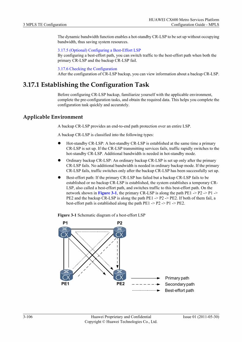
The dynamic bandwidth function enables a hot-standby CR-LSP to be set up without occupyingbandwidth, thus saving system resources.
3.17.5 (Optional) Configuring a Best-Effort LSPBy configuring a best-effort path, you can switch traffic to the best-effort path when both theprimary CR-LSP and the backup CR-LSP fail.
3.17.6 Checking the ConfigurationAfter the configuration of CR-LSP backup, you can view information about a backup CR-LSP.
3.17.1 Establishing the Configuration TaskBefore configuring CR-LSP backup, familiarize yourself with the applicable environment,complete the pre-configuration tasks, and obtain the required data. This helps you complete theconfiguration task quickly and accurately.
Applicable EnvironmentA backup CR-LSP provides an end-to-end path protection over an entire LSP.
A backup CR-LSP is classified into the following types:
l Hot-standby CR-LSP: A hot-standby CR-LSP is established at the same time a primaryCR-LSP is set up. If the CR-LSP transmitting services fails, traffic rapidly switches to thehot-standby CR-LSP. Additional bandwidth is needed in hot-standby mode.
l Ordinary backup CR-LSP: An ordinary backup CR-LSP is set up only after the primaryCR-LSP fails. No additional bandwidth is needed in ordinary backup mode. If the primaryCR-LSP fails, traffic switches only after the backup CR-LSP has been successfully set up.
l Best-effort path: If the primary CR-LSP has failed but a backup CR-LSP fails to beestablished or no backup CR-LSP is established, the system establishes a temporary CR-LSP, also called a best-effort path, and switches traffic to this best-effort path. On thenetwork shown in Figure 3-1, the primary CR-LSP is along the path PE1 -> P2 -> P1 ->PE2 and the backup CR-LSP is along the path PE1 -> P2 -> PE2. If both of them fail, abest-effort path is established along the path PE1 -> P2 -> P1 -> PE2.
Figure 3-1 Schematic diagram of a best-effort LSP
PE1 PE2
P1 P2
Primary pathSecondary pathBest-effort path
3 MPLS TE ConfigurationHUAWEI CX600 Metro Services Platform
Configuration Guide - MPLS
3-106 Huawei Proprietary and ConfidentialCopyright © Huawei Technologies Co., Ltd.
Issue 01 (2011-05-30)
Pre-configuration Tasks
Before configuring CR-LSP backup, complete the following tasks:
l Enabling MPLS, MPLS TE, and RSVP TE globally and in the interface view of each nodealong a backup CR-LSP (See Enabling MPLS TE and RSVP TE.)
Data Preparation
To configure CR-LSP backup, you need the following data.
No. Data
1 Backup mode
2 (Optional) Explicit path for the backup CR-LSP
3 (Optional) Affinity property of the backup CR-LSP
4 (Optional) Hop limit of the backup CR-LSP
3.17.2 Configuring CR-LSP BackupCR-LSP backup is configured on the ingress of a primary CR-LSP. Hot standby and ordinarybackup are mutually exclusive.
Context
By default, the CR-LSP backup is not enabled. After the CR-LSP backup is configured on theingress of a tunnel, the system automatically selects the path of the backup CR-LSP withoutmanual interruption.
NOTE
The CR-LSP backup cannot be configured with re-optimization at the same time.
Do as follows on the ingress node of the primary tunnel:
Procedure
Step 1 Run:system-view
The system view is displayed.
Step 2 Run:interface tunnel tunnel-number
The tunnel interface view of the MPLS TE tunnel is displayed.
Step 3 Run:mpls te backup { hot-standby [ wtr interval ] | ordinary }
The mode of establishing the CR-LSP backup is configured.
HUAWEI CX600 Metro Services PlatformConfiguration Guide - MPLS 3 MPLS TE Configuration
Issue 01 (2011-05-30) Huawei Proprietary and ConfidentialCopyright © Huawei Technologies Co., Ltd.
3-107
NOTE
A primary CR-LSP cannot function as a bypass tunnel or a backup CR-LSP for another CR-LSP. That is,the mpls te protected-interface or mpls te bypass-tunnel are mutually exclusive.
Step 4 (Optional) Run:mpls te path explicit-path path-name secondary
The explicit path used by the backup CR-LSP is specified.
NOTE
When an explicit path is used to set up a hot-standby CR-LSP, it cannot completely overlap the path of theprimary CR-LSP; otherwise, the hot-standby CR-LSP cannot protect the primary CR-LSP.
Step 5 (Optional) Run:mpls te affinity property properties [ mask mask-value ] secondary
The affinity property used by the backup CR-LSP is configured.
By default, the affinity property used by the backup CR-LSP is 0x0.
Step 6 (Optional) Run:mpls te hop-limit hop-limit-value secondary
The number of hops of the backup CR-LSP is limited.
By default, the hop limit of a backup CR-LSP is 32.
Step 7 Run:mpls te commit
The current tunnel configuration is committed.
----End
3.17.3 (Optional) Locking an Attribute Template for Backup CR-LSPs
You can configure the function of locking a CR-LSP attribute template to avoid unnecessarytraffic switchover.
ContextThe system provides three prioritized attribute templates for a hot-standby backup CR-LSP andthree for an ordinary backup CR-LSP. If an existing backup CR-LSP is set up using a lower-priority attribute template, the system automatically attempts to set up a new backup CR-LSPusing a higher-priority attribute template.
When a specified attribute template is locked, the system does not use a higher-priority attributetemplate to re-establish a CR-LSP even though the existing CR-LSP is set up using a lower-priority attribute template. This avoids unnecessary traffic switchover and thus saves systemresources.
Do as follows on the ingress of the primary CR-LSP:
Procedure
Step 1 Run:
3 MPLS TE ConfigurationHUAWEI CX600 Metro Services Platform
Configuration Guide - MPLS
3-108 Huawei Proprietary and ConfidentialCopyright © Huawei Technologies Co., Ltd.
Issue 01 (2011-05-30)
system-view
The system view is displayed.
Step 2 Run:interface tunnel tunnel-number
The tunnel interface view of the MPLS TE tunnel is displayed.
Step 3 Run:mpls te primary-lsp-constraint { dynamic | lsp-attribute lsp-attribute-name }
The CR-LSP attribute template is used to set up a primary CR-LSP.
Step 4 Run one of the following commands to use an attribute template to set up an ordinary backupCR-LSP or a hot-standby CR-LSP:l To set up a backup CR-LSP, run:
mpls te ordinary-lsp-constraint number { dynamic | lsp-attribute lsp-attribute-name }
l To set up a hot-standby CR-LSP, run:mpls te hotstandby-lsp-constraint number { dynamic | lsp-attribute lsp-attribute-name }
Step 5 Run one of the following commands to lock the attribute template that is used by an ordinarybackup CR-LSP or a hot-standby CR-LSP:l For the attribute template that is used to set up an ordinary backup CR-LSP, run:
mpls te backup ordinary-lsp-constraint lock
l For the attribute template that is used to set up a hot-standby CR-LSP, run:mpls te backup hotstandby-lsp-constraint lock
Step 6 Run:mpls te commit
The current tunnel configuration is committed.
----End
Follow-up Procedure
If you run the undo mpls te backup ordinary-lsp-constraint lock command or the undo mplste backup hotstandby-lsp-constraint lock command to unlock the attribute template, thesystem continues trying a higher-priority attribute template to set up a backup CR-LSP.
3.17.4 (Optional) Configuring the Dynamic Bandwidth Function fora Hot-standby CR-LSP
The dynamic bandwidth function enables a hot-standby CR-LSP to be set up without occupyingbandwidth, thus saving system resources.
Context
With the dynamic bandwidth function, a hot-standby CR-LSP occupies bandwidth resourcesonly when taking over traffic from a faulty primary CR-LSP, rather than when the primary CR-LSP works normally.
HUAWEI CX600 Metro Services PlatformConfiguration Guide - MPLS 3 MPLS TE Configuration
Issue 01 (2011-05-30) Huawei Proprietary and ConfidentialCopyright © Huawei Technologies Co., Ltd.
3-109
You can configure the dynamic bandwidth function for a hot-standby CR-LSP on the ingress ofa primary CR-LSP.
Procedurel Do as follows to configure a hot-standby CR-LSP that is set up without an attribute
template:
1. Run:system-view
The system view is displayed.
2. Run:interface tunnel tunnel-number
The tunnel interface view of the MPLS TE tunnel is displayed.
3. Run:tunnel-protocol mpls te
MPLS TE is configured as the tunneling protocol.
4. Run:mpls te backup hot-standby dynamic-bandwidth
The dynamic bandwidth function for the hot-standby CR-LSP is configured.
5. Run:mpls te commit
The configuration is committed.
l Do as follows to configure a hot-standby CR-LSP that is set up by using an attributetemplate:
1. Run:system-view
The system view is displayed.
2. Run:interface tunnel tunnel-number
The tunnel interface view of the MPLS TE tunnel is displayed.
3. Run:tunnel-protocol mpls te
MPLS TE is configured as the tunneling protocol.
4. Run:mpls te backup hotstandby-lsp-constraint dynamic-bandwidth
The dynamic bandwidth function for the hot-standby CR-LSP is configured.
5. Run:mpls te commit
The configuration is committed.
----End
3 MPLS TE ConfigurationHUAWEI CX600 Metro Services Platform
Configuration Guide - MPLS
3-110 Huawei Proprietary and ConfidentialCopyright © Huawei Technologies Co., Ltd.
Issue 01 (2011-05-30)
Follow-up Procedure
After the preceding configuration, the system can establish a new hot-standby CR-LSP usingthe required bandwidth according to the make-before-break mechanism to replace the hot-standby CR-LSP with bandwidth at 0 bit/s.
You can run the undo mpls te backup hot-standby dynamic-bandwidth command to deletethe dynamic bandwidth function for the hot-standby CR-LSP, thus allowing the hot-standby CR-LSP to re-occupy bandwidth.
3.17.5 (Optional) Configuring a Best-Effort LSPBy configuring a best-effort path, you can switch traffic to the best-effort path when both theprimary CR-LSP and the backup CR-LSP fail.
Context
In best-effort mode, do as follows on the ingress node of the TE tunnel:
Procedure
Step 1 Run:system-view
The system view is displayed.
Step 2 Run:interface tunnel tunnel-number
The tunnel interface view is displayed.
Step 3 Run:mpls te backup ordinary best-effort
A best-effort LSP is configured.
NOTE
The mpls te backup ordinary best-effort command and the mpls te backup ordinary command cannotbe configured on the same tunnel interface.
Step 4 (Optional) Run:mpls te affinity property properties [ mask mask-value ] best-effort
The affinity property used in the best-effort LSP is configured.
By default, the value of the affinity property used by the best-effort LSP is 0x0.
Step 5 (Optional) Run:mpls te hop-limit hop-limit-value best-effort
The number of hops of the best-effort LSP is limited.
By default, the hop limit of a backup CR-LSP is 32.
Step 6 Run:mpls te commit
HUAWEI CX600 Metro Services PlatformConfiguration Guide - MPLS 3 MPLS TE Configuration
Issue 01 (2011-05-30) Huawei Proprietary and ConfidentialCopyright © Huawei Technologies Co., Ltd.
3-111
The current tunnel configuration is committed.
----End
Follow-up ProcedureAfter a best-effort LSP is configured, the device triggers the setup of a best-effort LSP whenboth the primary LSP and the backup LSP fail.
3.17.6 Checking the ConfigurationAfter the configuration of CR-LSP backup, you can view information about a backup CR-LSP.
Procedurel Run the display mpls te tunnel-interface [ tunnel tunnel-number ] command to check
information about the tunnel interface.l Run the display mpls te hot-standby state { all [ verbose ] | interface tunnel interface-
number } command to check the hot standby status.l Run the display mpls te tunnel [ destination ip-address ] [ lsp-id ingress-lsr-id session-
id local-lsp-id ] [lsr-role { all | egress | ingress | remote | transit } ] [ name tunnel-name ] [ { incoming-interface | interface | outgoing-interface } interface-type interface-number ] [ te-class0 | te-class1 | te-class2 | te-class3 | te-class4 | te-class5 | te-class6 | te-class7 ] [ verbose ] command to check information about the tunnel.
----End
ExampleIn hot standby mode, after the configuration, run the display mpls te tunnel-interfacecommand, and you can view information about a backup CR-LSP.[HUAWEI] display mpls te tunnel-interface================================================================ Tunnel1/0/0 ================================================================ Tunnel State Desc : UP Active LSP : Hot-Standby LSP Session ID : 100 Ingress LSR ID : 4.4.4.4 Egress LSR ID: 3.3.3.3 Admin State : UP Oper State : UP Primary LSP State : DOWN Main LSP State : SETTING UP Hot-Standby LSP State : UP Main LSP State : READY LSP ID : 32769 Modify LSP State : SETTING UP
Run the display mpls te hot-standby state command, and you can view information about thehot standby.<HUAWEI> display mpls te hot-standby state interface Tunnel 1/0/0----------------------------------------------------------------Verbose information about the Tunnel1/0/0 hot-standby state----------------------------------------------------------------session id : 100main LSP token : 0x100201ahot-standby LSP token : 0x100201bHSB switch result : Best-Effort LSPWTR : 15s
Run the display mpls te tunnel to check information about the tunnel.
3 MPLS TE ConfigurationHUAWEI CX600 Metro Services Platform
Configuration Guide - MPLS
3-112 Huawei Proprietary and ConfidentialCopyright © Huawei Technologies Co., Ltd.
Issue 01 (2011-05-30)
<HUAWEI> display mpls te tunnel verbose No : 1 Tunnel-Name : Tunnel1/0/0 TunnelIndex : 0 LSP Index : 1024 Session ID : 100 LSP ID : 1 Lsr Role : Ingress LSP Type : Primary Ingress LSR ID : 1.1.1.1 Egress LSR ID : 2.2.2.2 In-Interface : - Out-Interface : Pos1/0/0 Sign-Protocol : Static CR Resv Style : IncludeAnyAff : 0x0 ExcludeAnyAff : 0x0 IncludeAllAff : 0x0 LspConstraint : 1 ER-Hop Table Index : - AR-Hop Table Index: - C-Hop Table Index : - PrevTunnelIndexInSession: - NextTunnelIndexInSession: - PSB Handle : 0 Created Time : 2008/04/03 19:31:14 -------------------------------- DS-TE Information -------------------------------- Bandwidth Reserved Flag : Unreserved CT0 Bandwidth(Kbit/sec) : 0 CT1 Bandwidth(Kbit/sec): 0 CT2 Bandwidth(Kbit/sec) : 0 CT3 Bandwidth(Kbit/sec): 0 CT4 Bandwidth(Kbit/sec) : 0 CT5 Bandwidth(Kbit/sec): 0 CT6 Bandwidth(Kbit/sec) : 0 CT7 Bandwidth(Kbit/sec): 0 Setup-Priority : 0 Hold-Priority : 0 -------------------------------- FRR Information -------------------------------- Primary LSP Info TE Attribute Flag : 0xe3 Protected Flag : 0x04 Bypass In Use : Not Exists Bypass Tunnel Id : - BypassTunnel : - Bypass Lsp ID : - FrrNextHop : - ReferAutoBypassHandle : - FrrPrevTunnelTableIndex : - FrrNextTunnelTableIndex: - Bypass Attribute(Not configured) Setup Priority : - Hold Priority : - HopLimit : - Bandwidth : - IncludeAnyGroup : - ExcludeAnyGroup : - IncludeAllGroup : - Bypass Unbound Bandwidth Info(Kbit/sec) CT0 Unbound Bandwidth : - CT1 Unbound Bandwidth: - CT2 Unbound Bandwidth : - CT3 Unbound Bandwidth: - CT4 Unbound Bandwidth : - CT5 Unbound Bandwidth: - CT6 Unbound Bandwidth : - CT7 Unbound Bandwidth: - -------------------------------- BFD Information -------------------------------- NextSessionTunnelIndex : - PrevSessionTunnelIndex: - NextLspId : - PrevLspId : -
3.18 Configuring Synchronization of the Bypass Tunnel andthe Backup CR-LSP
This section describes that after the primary CR-LSP is faulty, the system starts the TE FRRbypass tunnel and tries to restore the primary CR-LSP the same time it sets up a backup CR-LSP.
3.18.1 Establishing the Configuration Task
HUAWEI CX600 Metro Services PlatformConfiguration Guide - MPLS 3 MPLS TE Configuration
Issue 01 (2011-05-30) Huawei Proprietary and ConfidentialCopyright © Huawei Technologies Co., Ltd.
3-113
Before configuring synchronization of the bypass tunnel and the backup CR-LSP, familiarizeyourself with the applicable environment, complete the pre-configuration tasks, and obtain therequired data. This can help you complete the configuration task quickly and accurately.
3.18.2 Enabling Synchronization of the Bypass Tunnel and the Backup CR-LSPBy configuring synchronization of the bypass tunnel and the backup CR-LSP, you can protectthe entire CR-LSP.
3.18.3 Checking the ConfigurationAfter the configuration of synchronization of the bypass tunnel and the backup CR-LSP, youcan view information about the bypass tunnel and the backup CR-LSP.
3.18.1 Establishing the Configuration TaskBefore configuring synchronization of the bypass tunnel and the backup CR-LSP, familiarizeyourself with the applicable environment, complete the pre-configuration tasks, and obtain therequired data. This can help you complete the configuration task quickly and accurately.
Application Environment
To protect important links and nodes, you can configure the TE FRR bypass tunnel and the end-to-end backup CR-LSP together. The backup CR-LSP is more reliable than the TE FRR bypasstunnel. Therefore, to improve the security of the tunnel, you are recommended to configuresynchronization of the TE FRR bypass tunnel and the backup CR-LSP.
l In ordinary backup mode, the following situations occur:
– When the protected link or node is faulty, the system switches traffic to the TE FRRbypass tunnel and tries to restore the primary CR-LSP. At the same time, the systemtries to set up a backup CR-LSP.
– When the backup CR-LSP is set up successfully and the primary CR-LSP is not restored,traffic is switched to the backup CR-LSP.
– When the backup CR-LSP fails to be set up and the primary CR-LSP is not restored,traffic still passes through the TE FRR bypass tunnel.
l In hot standby mode, the following situations occur:
– If the backup CR-LSP is in the Up state and the protected link or node is faulty, trafficis switched to the TE FRR bypass tunnel and then immediately switched to the backupCR-LSP. At the same time, the system tries to restore the primary CR-LSP.
– If the backup CR-LSP is in the Down state, the processing of hot standby is the sameas the processing of ordinary backup.
When the primary CR-LSP is Up and the hot standby CR-LSP is also in the Up state, morebandwidth resources are needed. The ordinary CR-LSP is set up only when the primary CR-LSPis in the FRR-in-use state. That is, when the primary CR-LSP works normally, no morebandwidth resources are needed. Therefore, the ordinary backup is recommended.
Pre-configuration Tasks
Before configuring synchronization of the bypass tunnel and the backup CR-LSP, you need tocomplete the following tasks:
l Setting up the primary tunnel
3 MPLS TE ConfigurationHUAWEI CX600 Metro Services Platform
Configuration Guide - MPLS
3-114 Huawei Proprietary and ConfidentialCopyright © Huawei Technologies Co., Ltd.
Issue 01 (2011-05-30)
l Configuring manual MPLS TE FRR or MPLS TE Auto FRR (See the section ConfiguringMPLS TE FRR or the section Configuring MPLS Auto TE FRR.)
l Configuring the backup CR-LSP (except for the best-effort path) in either hot standby modeor ordinary backup mode (See the section Configuring CR-LSP Backup.)
Data PreparationTo configure synchronization of the bypass tunnel and the backup CR-LSP, you need thefollowing data.
No. Data
1 Protection policy of TE FRR, that is, to protect the link or the node
2 Backup mode
3.18.2 Enabling Synchronization of the Bypass Tunnel and theBackup CR-LSP
By configuring synchronization of the bypass tunnel and the backup CR-LSP, you can protectthe entire CR-LSP.
ContextDo as follows on the ingress LSR of the primary tunnel:
NOTE
Before the configuration, you must configure the end-to-end protection (except for the best-effort path) ineither hot standby mode or ordinary backup mode and the TE FRR partial protection.
Procedure
Step 1 Run:system-view
The system view is displayed.
Step 2 Run:interface tunnel tunnel-number
The tunnel interface view of the MPLS TE tunnel is displayed.
Step 3 Run:mpls te backup frr-in-use
When the primary CR-LSP is faulty (that is, the primary CR-LSP is in FRR-in-use state), thesystem starts the TE FRR bypass tunnel and tries to restore the primary CR-LSP. At the sametime, the system tries to set up a backup CR-LSP.
Step 4 Run:mpls te commit
The tunnel configurations are committed.
HUAWEI CX600 Metro Services PlatformConfiguration Guide - MPLS 3 MPLS TE Configuration
Issue 01 (2011-05-30) Huawei Proprietary and ConfidentialCopyright © Huawei Technologies Co., Ltd.
3-115
Step 5 Run:quit
Return to the system view.
----End
3.18.3 Checking the ConfigurationAfter the configuration of synchronization of the bypass tunnel and the backup CR-LSP, youcan view information about the bypass tunnel and the backup CR-LSP.
PrerequisiteAll configurations of synchronization of the bypass tunnel and the backup CR-LSP are complete.
Procedurel Run the display mpls te tunnel-interface [ tunnel tunnel-number | auto-bypass-tunnel
tunnel-name ] command, and you can view information about the tunnel.
----End
3.19 Configuring RSVP GRThis section describes how to configure RSVP-TE GR so that devices along an RSVP-TE tunnelcan retain RSVP sessions during a master/slave switchover.
3.19.1 Establishing the Configuration TaskBefore configuring RSVP-TE GR, familiarize yourself with the applicable environment,complete the pre-configuration tasks, and obtain the data required for the configuration. Thiswill help you complete the configuration task quickly and accurately.
3.19.2 Enabling the RSVP Hello Extension FunctionBy configuring the RSVP Hello extension, you can enable a device to quickly check reachabilitybetween RSVP nodes.
3.19.3 Enabling Full GR of RSVPBy enabling RSVP full GR, you can ensure uninterrupted data transmission on the forwardingplane.
3.19.4 (Optional) Enabling the RSVP GR Support FunctionBy being enabled with RSVP GR, a device supports the GR capability of its neighbor.
3.19.5 (Optional) Configuring Hello Sessions Between RSVP GR NodesOn a network enabled with TE FRR, a Hello session needs to be set up between a PLR and anMP.
3.19.6 (Optional) Modifying Basic TimeBy setting the basic time and the number of ingress LSPs, you can modify the restart time.
3.19.7 Checking the ConfigurationAfter the configuration of RSVP GR, you can view that the TE tunnel properly forward dataduring the GR process.
3 MPLS TE ConfigurationHUAWEI CX600 Metro Services Platform
Configuration Guide - MPLS
3-116 Huawei Proprietary and ConfidentialCopyright © Huawei Technologies Co., Ltd.
Issue 01 (2011-05-30)
3.19.1 Establishing the Configuration TaskBefore configuring RSVP-TE GR, familiarize yourself with the applicable environment,complete the pre-configuration tasks, and obtain the data required for the configuration. Thiswill help you complete the configuration task quickly and accurately.
Applicable Environment
When an RSVP node performs an active/standby switchover, an RSVP adjacency relationshipbetween the local node and its neighbor is torn down because of signaling protocol timeout,resulting in removal of a CR-LSP and a temporary traffic interruption.
RSVP GR resolves the preceding problem. The RSVP GR mechanism allows the adjacencyrelationship to be reestablished between neighbors without tearing down RSVP sessions.
On the CX600, FRR switching is performed during the RSVP GR process. FRR protects trafficif a switchover is performed on the PLR node, PLR upstream node, MP, or MP downstreamnode and the outgoing interface of the PLR primary tunnel fails, reducing the fault period.
NOTE
When FRR is performed during the RSVP GR process, setting the timeout multiplier in the PSB and RSBto a value equal to or greater than five is recommended, preventing PSB and RSB loss due to oversizeddata. For detailed configurations, see (Optional) Modifying the PSB and RSB Timeout Multiplier.
Pre-configuration Tasks
Before configuring RSVP GR, complete the following tasks:
l Configuring an RSVP-TE tunnell Enabling IS-IS GR or OSPF GR on each LSR
Data Preparation
To configure RSVP GR, you need the following data.
No. Data
1 IGP parameters:l IS-IS: IS-IS process ID, Network Entity Title (NET), and IS-IS level of each nodel OSPF: OSPF process ID and AS number
2 MPLS LSR ID of each node
3 Tunnel interface number and tunnel ID
4 (Optional) Basic RSVP GR time
3.19.2 Enabling the RSVP Hello Extension FunctionBy configuring the RSVP Hello extension, you can enable a device to quickly check reachabilitybetween RSVP nodes.
HUAWEI CX600 Metro Services PlatformConfiguration Guide - MPLS 3 MPLS TE Configuration
Issue 01 (2011-05-30) Huawei Proprietary and ConfidentialCopyright © Huawei Technologies Co., Ltd.
3-117
ContextDo as follows on a GR node and its neighboring nodes:
Procedure
Step 1 Run:system-view
The system view is displayed.
Step 2 Run:mpls
The MPLS view is displayed.
Step 3 Run:mpls rsvp-te hello
The RSVP Hello extension function is enabled globally.
Step 4 Run:quit
The system view is displayed.
Step 5 Run:interface interface-type interface-number
The RSVP interface view is displayed.
Step 6 Run:mpls rsvp-te hello
The RSVP Hello extension function is enabled on the interface.
By default, although the RSVP Hello extension function has been enabled globally, it is disabledon RSVP-enabled interfaces.
----End
3.19.3 Enabling Full GR of RSVPBy enabling RSVP full GR, you can ensure uninterrupted data transmission on the forwardingplane.
ContextDo as follows on a GR node:
Procedure
Step 1 Run:system-view
The system view is displayed.
Step 2 Run:mpls
3 MPLS TE ConfigurationHUAWEI CX600 Metro Services Platform
Configuration Guide - MPLS
3-118 Huawei Proprietary and ConfidentialCopyright © Huawei Technologies Co., Ltd.
Issue 01 (2011-05-30)
The MPLS view is displayed.
Step 3 Run:mpls rsvp-te hello full-gr
The RSVP GR function and the function of supporting RSVP GR on a neighbor are enabled.
By default, the RSVP GR function and RSVP GR support function are disabled.
----End
3.19.4 (Optional) Enabling the RSVP GR Support FunctionBy being enabled with RSVP GR, a device supports the GR capability of its neighbor.
Context
RSVP GR takes effect on the RSVP GR-enabled neighbor automatically after the neighbor isenabled with RSVP full GR. If the GR node's neighbor is a GR node, do not perform the followingsteps. If the GR node's neighbor is not a GR node, do as follows:
Procedure
Step 1 Run:system-view
The system view is displayed.
Step 2 Run:mpls
The MPLS view is displayed.
Step 3 Run:mpls rsvp-te
RSVP-TE is enabled.
Step 4 Run:mpls rsvp-te hello
The RSVP Hello function is enabled on the local node.
Step 5 Run:mpls rsvp-te hello support-peer-gr
The function of supporting RSVP GR on the neighbor is enabled.
----End
3.19.5 (Optional) Configuring Hello Sessions Between RSVP GRNodes
On a network enabled with TE FRR, a Hello session needs to be set up between a PLR and anMP.
HUAWEI CX600 Metro Services PlatformConfiguration Guide - MPLS 3 MPLS TE Configuration
Issue 01 (2011-05-30) Huawei Proprietary and ConfidentialCopyright © Huawei Technologies Co., Ltd.
3-119
Context
If TE FRR is deployed, a hello session is required between a PLR and an MP. Do as follows onthe PLR and MP:
Procedure
Step 1 Run:system-view
The system view is displayed.
Step 2 Run:mpls
The MPLS view is displayed.
Step 3 Run:mpls rsvp-te
RSVP-TE is enabled.
Step 4 Run:mpls rsvp-te hello
The RSVP Hello function is enabled on the local node.
Step 5 Run:mpls rsvp-te hello nodeid-session ip-address
A Hello session is set up between a restarting node and a neighbor node.
ip-address is the LSR ID of the RSVP neighbor.
----End
3.19.6 (Optional) Modifying Basic TimeBy setting the basic time and the number of ingress LSPs, you can modify the restart time.
Context
After an active/standby switchover starts, an RSVP GR node has an RSVP smoothing period,during which the data plane continues forwarding data if the control plane is not restored. AfterRSVP smoothing is completed, a restart timer is started.
Restart timer value = Basic time + Number of ingress LSPs x 60 ms
In this formula, the default basic time is 90 seconds and is configurable by using a commandline, and the number of LSPs is the number of LSPs with the local node being the ingress.
After the restart timer expires, the recovery timer is started.
Recovery timer = Restart time + Total number of LSPs x 40 ms
Do as follows on the GR node to modify the basic time:
3 MPLS TE ConfigurationHUAWEI CX600 Metro Services Platform
Configuration Guide - MPLS
3-120 Huawei Proprietary and ConfidentialCopyright © Huawei Technologies Co., Ltd.
Issue 01 (2011-05-30)
Procedure
Step 1 Run:system-view
The system view is displayed.
Step 2 Run:mpls
The MPLS view is displayed.
Step 3 Run:mpls rsvp-te hello basic-restart-time basic-restart-time
The RSVP GR basic time is modified.
By default, the RSVP GR basic time is 90 seconds.
----End
3.19.7 Checking the ConfigurationAfter the configuration of RSVP GR, you can view that the TE tunnel properly forward dataduring the GR process.
Procedurel Run the display mpls rsvp-te graceful-restart command to check the status of the local
RSVP GR.l Run the display mpls rsvp-te graceful-restart peer [ { interface interface-type interface-
number | node-id } [ ip-address ] ] command to check the status of RSVP GR on a neighbor.
----End
ExampleRun the display mpls rsvp-te graceful-restart command on a restarted node. If "GR-Self GR-Support" is displayed in the Graceful-Restart Capability field, it means that the local device hasthe RSVP GR function. During the GR process, in the output of the display mpls rsvp-tegraceful-restart command, "Restart time going on" or "Recovery time going on" is displayedin the GR Status field.
Run the display mpls rsvp-te graceful-restart peer command on the restarted node.
Information displayed in the Neighbor Capability field has specific meanings:
l Can Do Self GR: means that the neighbor node is enabled with the RSVP GR capability.l Can Support GR: means that the neighbor node is enabled with the RSVP GR supporting
capability.l Both "Can Do Self GR" and "Can Support GR": mean that the neighbor node is enabled
with the RSVP GR function and the RSVP GR support function.
Run the ping lsp te tunnel command on the neighbor node and immediately run the slaveswitchover command in the system view on the restarted node, and you can view that dataforwarded through the TE tunnel is not interrupted during GR.
HUAWEI CX600 Metro Services PlatformConfiguration Guide - MPLS 3 MPLS TE Configuration
Issue 01 (2011-05-30) Huawei Proprietary and ConfidentialCopyright © Huawei Technologies Co., Ltd.
3-121
3.20 Configuring Static BFD for CR-LSPThis section describes how to configure a static BFD session to detect link faults in static CR-LSPs or RSVP CR-LSPs.
3.20.1 Establishing the Configuration TaskBefore configuring static BFD for CR-LSP, familiarize yourself with the applicableenvironment, complete the pre-configuration tasks, and obtain the data required for theconfiguration. This will help you complete the configuration task quickly and accurately.
3.20.2 Enabling BFD GloballyTo configure static BFD for CR-LSP, you must enable BFD globally on the ingress node andthe egress node of a tunnel.
3.20.3 Configuring BFD Parameters on the Ingress of the TunnelThe BFD parameters configured on the ingress node include the local and remote discriminators,local minimum intervals at which BFD packets are sent and received, and BFD detectionmultiplier, which determine the establishment of a BFD session.
3.20.4 Configuring BFD Parameters on the Egress of the TunnelThe BFD parameters configured on the egress node include the local and remote discriminators,local minimum intervals at which BFD packets are sent and received, and BFD detectionmultiplier, which determine the establishment of a BFD session.
3.20.5 Checking the ConfigurationAfter the configuration of static BFD for CR-LSP, you can view that the status of a BFD sessionis Up.
3.20.1 Establishing the Configuration TaskBefore configuring static BFD for CR-LSP, familiarize yourself with the applicableenvironment, complete the pre-configuration tasks, and obtain the data required for theconfiguration. This will help you complete the configuration task quickly and accurately.
Applicable EnvironmentBFD detects the following types of CR-LSPs:l Static CR-LSPl RSVP CR-LSP
BFD for static CR-LSP and BFD for RSVP CR-LSP can be used to replace MPLS OAM todetect the MPLS TE tunnel protection groups and trigger primary/backup CR-LSP switchover.BFD for CR-LSP is applicable to the hot-standby CR-LSP. It detects the primary and backupCR-LSPs and triggers CR-LSPs switchover.
For details about MPLS OAM configuration, refer to the chapter "MPLS OAM Configuration"in the Configuration Guide - MPLS.
3 MPLS TE ConfigurationHUAWEI CX600 Metro Services Platform
Configuration Guide - MPLS
3-122 Huawei Proprietary and ConfidentialCopyright © Huawei Technologies Co., Ltd.
Issue 01 (2011-05-30)
NOTE
For the same CR-LSP, MPLS OAM and BFD cannot be configured simultaneously.
In the scenario that static BFD for CR-LSP is applied and the BFD status is Up, if the tunnel interface towhich CR-LSP belongs is shut down, the BFD status remains Up.
BFD for LSP can function properly though the forward path is an LSP and the backward path is an IP link.The forward path and the backward path must be established over the same link; otherwise, if a fault occurs,BFD cannot identify the faulty path. Before deploying BFD, ensure that the forward and backward pathsare over the same link so that BFD can correctly identify the faulty path.
Pre-configuration Tasks
Before configuring static BFD for CR-LSP, complete the following task:
l Configuring Static MPLS TE Tunnel or Configuring RSVP-TE Tunnel or MPLS TEtunnel protection group
NOTE
For details about the configuration of the MPLS TE tunnel protection group for the MPLS TE tunnel, referto the chapter "MPLS OAM Configuration" in the HUAWEI CX600 Metro Services Platform ConfigurationGuide - MPLS.
Data Preparation
To configure static BFD for CR-LSP, you need the following data.
No. Data
1 BFD session name
2 Backward channel (IP link, dynamic LSP, static LSP, or MPLS TE tunnel)
3 Local and remote discriminators of the BFD session
4 Minimum interval for sending BFD packets
5 Minimum interval for receiving BFD packets
6 Local BFD detection multiplier
3.20.2 Enabling BFD GloballyTo configure static BFD for CR-LSP, you must enable BFD globally on the ingress node andthe egress node of a tunnel.
Context
Do as follows on the ingress node and egress node of the tunnel:
Procedure
Step 1 Run:system-view
HUAWEI CX600 Metro Services PlatformConfiguration Guide - MPLS 3 MPLS TE Configuration
Issue 01 (2011-05-30) Huawei Proprietary and ConfidentialCopyright © Huawei Technologies Co., Ltd.
3-123
The system view is displayed.
Step 2 Run:bfd
BFD is enabled globally.
----End
3.20.3 Configuring BFD Parameters on the Ingress of the TunnelThe BFD parameters configured on the ingress node include the local and remote discriminators,local minimum intervals at which BFD packets are sent and received, and BFD detectionmultiplier, which determine the establishment of a BFD session.
ContextDo as follows on the ingress node of a tunnel:
Procedure
Step 1 Run:system-view
The system view is displayed.
Step 2 Run:bfd cfg-name bind mpls-te interface tunnel tunnel-number te-lsp [ backup ]
BFD is configured to detect the primary or backup CR-LSP bound to a specified tunnel.
The parameter backup means that backup CR-LSPs are to be checked.
Step 3 Run:discriminator local discr-value
The local discriminator is set.
Step 4 Run:discriminator remote discr-value
The remote discriminator is set.
Step 5 (Optional) Run:min-tx-interval interval
The local minimum interval at which BFD packets are sent is set.
The default value is specified in the license.
Step 6 (Optional) Run:min-rx-interval interval
The local minimum interval at which BFD packets are received is set.
The default value is specified in the license.
Step 7 (Optional) Run:detect-multiplier multiplier
3 MPLS TE ConfigurationHUAWEI CX600 Metro Services Platform
Configuration Guide - MPLS
3-124 Huawei Proprietary and ConfidentialCopyright © Huawei Technologies Co., Ltd.
Issue 01 (2011-05-30)
The local detection multiplier is adjusted.
By default, the local detection multiplier is 3.
Step 8 Run:process-pst
The system is enabled to change the port status table (PST) when the BFD status changes.
When the BFD status changes, BFD notifies the application of the change, triggering a fastswitchover between the primary and bypass CR-LSPs.
Step 9 Run:commit
The current configuration is committed.
NOTE
Actual local sending interval = MAX { Configured local sending interval, Configured remote receivinginterval }Actual local receiving interval = MAX { Configured remote sending interval, Configured local receivinginterval }Actual local detection interval = Actual local receiving interval x Configured remote detection multiplierFor example:
l The local sending and receiving intervals are set to 200 ms and 300 ms respectively and the detectionmultiplier is set to 4.
l The remote sending and receiving intervals are set to 100 ms and 600 ms respectively and the detectionmultiplier is set to 5.
Then,
l Actual local sending interval = MAX {200 ms, 600 ms} = 600 ms; Actual local receiving interval =MAX {100 ms, 300 ms} = 300 ms; Actual local detection interval is 300 ms x 5 = 1500 ms.
l Actual remote sending interval = MAX {100 ms, 300 ms} = 300 ms; Actual remote receiving interval= MAX {200 ms, 600 ms} = 600 ms; Actual remote detection interval is 600 ms x 4 = 2400 ms.
----End
3.20.4 Configuring BFD Parameters on the Egress of the TunnelThe BFD parameters configured on the egress node include the local and remote discriminators,local minimum intervals at which BFD packets are sent and received, and BFD detectionmultiplier, which determine the establishment of a BFD session.
ContextDo as follows on the egress node of a tunnel:
Procedure
Step 1 Run:system-view
The system view is displayed.
Step 2 Configure a reverse tunnel to inform the ingress of a fault if the fault occurs. The reverse tunnelcan be the IP link, LSP, or TE tunnel. To prevent affecting BFD detection, an IP link is usuallyselected to inform the ingress of an LSP fault. The process-pst command is not allowed if a
HUAWEI CX600 Metro Services PlatformConfiguration Guide - MPLS 3 MPLS TE Configuration
Issue 01 (2011-05-30) Huawei Proprietary and ConfidentialCopyright © Huawei Technologies Co., Ltd.
3-125
reverse tunnel is configured. If the configured reverse tunnel requires BFD detection, configurea pair of BFD sessions for it. Choose one of the following configurations as required:
l For an IP link, run:bfd cfg-name bind peer-ip ip-address [ vpn-instance vpn-name ] [ interface interface-type interface-number] [ source-ip ip-address ]
l For an LDP LSP, run:bfd cfg-name bind ldp-lsp peer-ip ip-address nexthop ip-address [ interface interface-type interface-number ]
l For a static LSP, run:bfd cfg-name bind static-lsp lsp-name
l For a CR-LSP, run:bfd cfg-name bind mpls-te interface tunnel tunnel-number te-lsp [ backup ]
l For a TE tunnel, run:bfd cfg-name bind mpls-te interface tunnel tunnel-number
Step 3 Run:discriminator local discr-value
The local discriminator is set.
Step 4 Run:discriminator remote discr-value
The remote discriminator is set.
Step 5 (Optional) Run:min-tx-interval interval
The minimum interval at which the local end sends BFD packets is set.
The default value is specified by the license.
Step 6 (Optional) Run:min-rx-interval interval
The minimum interval at which the local end receives BFD packets is set.
The default value is specified by the license.
Step 7 (Optional) Run:detect-multiplier multiplier
The local detection multiplier is set.
Step 8 Run:commit
The configuration is committed.
----End
3.20.5 Checking the ConfigurationAfter the configuration of static BFD for CR-LSP, you can view that the status of a BFD sessionis Up.
3 MPLS TE ConfigurationHUAWEI CX600 Metro Services Platform
Configuration Guide - MPLS
3-126 Huawei Proprietary and ConfidentialCopyright © Huawei Technologies Co., Ltd.
Issue 01 (2011-05-30)
Procedurel Run the display bfd configuration mpls-te interface tunnel interface-number te-lsp
[ verbose ] command to check BFD configurations on the ingress.l Run the following commands to check BFD configurations on the egress:
– Run the display bfd configuration all [ for-ip | for-lsp | for-te ] [ verbose ] commandto check all BFD configurations.
– Run the display bfd configuration static [ for-ip | for-lsp | for-te | name cfg-name ][ verbose ] command to check the static BFD configurations.
– Run the display bfd configuration peer-ip peer-ip [ vpn-instance vpn-instance-name ] [ verbose ] command to check the configurations of BFD with the reverse pathbeing an IP link.
– Run the display bfd configuration static-lsp lsp-name [ verbose ] command to checkthe configurations of BFD with the reverse path being a static LSP.
– Run the display bfd configuration ldp-lsp peer-ip peer-ip nexthop nexthop [interface interface-type interface-number ] [ verbose ] command to check theconfigurations of BFD with the backward channel being an LDP LSP.
– Run the display bfd configuration mpls-te interface tunnel interface-number te-lsp[ verbose ] command to check the configurations of BFD with the backward channelbeing a CR-LSP.
– Run the display bfd configuration mpls-te interface tunnel interface-number[ verbose ] command to check the configurations of BFD with the backward channelbeing a TE tunnel.
l Run the display bfd session mpls-te interface tunnel interface-number te-lsp[ verbose ] command to check BFD session configurations on the ingress.
l Run the following commands to check BFD session configurations on the egress:
– Run the display bfd session all [ for-ip | for-lsp | for-te ] [ slot slot-id | verbose ]command to check all the BFD configurations.
– Run the display bfd session static [ for-ip | for-lsp | for-te ] [ slot slot-id | verbose ]command to check the static BFD configurations.
– Run the display bfd session peer-ip peer-ip [ vpn-instance vpn-instance-name ][ slot slot-id | verbose ] command to check the configurations of BFD with the backwardchannel being an IP link.
– Run the display bfd session static-lsp lsp-name [ verbose ] command to check theconfigurations of BFD with the backward channel being a static LSP.
– Run the display bfd session ldp-lsp peer-ip peer-ip [ interface interface-typeinterface-number ] [ verbose ] command to check the configurations of BFD with thebackward channel being an LDP LSP.
– Run the display bfd session mpls-te interface tunnel interface-number te-lsp[ verbose ] command to check the configurations of BFD with the backward channelbeing a CR-LSP.
– Run the display bfd session mpls-te interface tunnel interface-number [ verbose ]command to check the configurations of BFD with the backward channel being a TEtunnel.
l Run the following command to check BFD statistics:
– Run the display bfd statistics [ slot slot-id ] command to check all BFD statistics.
HUAWEI CX600 Metro Services PlatformConfiguration Guide - MPLS 3 MPLS TE Configuration
Issue 01 (2011-05-30) Huawei Proprietary and ConfidentialCopyright © Huawei Technologies Co., Ltd.
3-127
– Run the display bfd statistics session all [ for-ip | for-lsp | for-te ] [ slot slot-id ]command to check all BFD session statistics.
– Run the display bfd statistics session peer-ip peer-ip [ vpn-instance vpn-instance-name ] [ slot slot-id ] command to check statistics about the BFD session that detectsfaults in the IP link.
– Run the display bfd statistics session static-lsp lsp-name command to check statisticsabout the BFD session that detects faults in the static LSP.
– Run the display bfd statistics session ldp-lsp peer-ip peer-ip [ interface interface-type interface-number ] command to check statistics of the BFD session that detectsfaults in the LDP LSP.
– Run the display bfd statistics session mpls-te interface tunnel interface-number te-lsp command to check statistics about the BFD session that detects faults in the CR-LSP.
----End
ExampleAfter the configuration, run the preceding commands to check BFD session status, and you canview that the BFD session is Up.
3.21 Configuring Static BFD for TEThis section describes how to configure a static BFD session to detect faults in a TE tunnel.
3.21.1 Establishing the Configuration TaskBefore configuring static BFD for TE, familiarize yourself with the applicable environment,complete the pre-configuration tasks, and obtain the data required for the configuration. Thiswill help you complete the configuration task quickly and accurately.
3.21.2 Enabling BFD GloballyTo configure static BFD for TE, you need to enable BFD globally on the ingress and egressnodes of a tunnel.
3.21.3 Configuring BFD Parameters on the Ingress of the TunnelThe BFD parameters configured on the ingress node include the local and remote discriminators,local minimum intervals at which BFD packets are sent and received, and BFD detectionmultiplier, which determine the establishment of a BFD session.
3.21.4 Configuring BFD Parameters on the Egress of the TunnelThe BFD parameters configured on the egress node include the local and remote discriminators,local minimum intervals at which BFD packets are sent and received, and BFD detectionmultiplier, which determine the establishment of a BFD session.
3.21.5 Checking the ConfigurationAfter the configuration of static BFD for TE, you can view that the status of a BFD session isUp.
3.21.1 Establishing the Configuration TaskBefore configuring static BFD for TE, familiarize yourself with the applicable environment,complete the pre-configuration tasks, and obtain the data required for the configuration. Thiswill help you complete the configuration task quickly and accurately.
3 MPLS TE ConfigurationHUAWEI CX600 Metro Services Platform
Configuration Guide - MPLS
3-128 Huawei Proprietary and ConfidentialCopyright © Huawei Technologies Co., Ltd.
Issue 01 (2011-05-30)
Applicable EnvironmentBFD for TE allows applications such as VPN FRR or VLL FRR to fast switch traffic if theprimary tunnel fails, preventing service interruption.
NOTE
MPLS OAM and BFD cannot be configured together on a TE tunnel.BFD for LSP can function properly though the forward path is an LSP and the backward path is an IP link.The forward path and the backward path must be established over the same link; otherwise, if a fault occurs,BFD cannot identify the faulty path. Before deploying BFD, ensure that the forward and backward pathsare over the same link so that BFD can correctly identify the faulty path.
Pre-configuration TasksBefore configuring static BFD for TE, complete the following task:
l Configuring Static MPLS TE Tunnel or Configuring RSVP-TE Tunnel
Data PreparationTo configure static BFD for TE, you need the following data.
No. Data
1 Name of the BFD session
2 Backward channel (IP link, dynamic LSP, static LSP, or MPLS TE tunnel)
3 Local and remote discriminators of the BFD session
4 (Optional) Local minimum interval at which BFD packets are sent
5 (Optional) Local minimum interval at which BFD packets are received
6 (Optional) Local detection multiplier
3.21.2 Enabling BFD GloballyTo configure static BFD for TE, you need to enable BFD globally on the ingress and egressnodes of a tunnel.
ContextDo as follows on the ingress and egress of a tunnel:
Procedure
Step 1 Run:system-view
The system view is displayed.
Step 2 Run:bfd
HUAWEI CX600 Metro Services PlatformConfiguration Guide - MPLS 3 MPLS TE Configuration
Issue 01 (2011-05-30) Huawei Proprietary and ConfidentialCopyright © Huawei Technologies Co., Ltd.
3-129
BFD is enabled globally.
----End
3.21.3 Configuring BFD Parameters on the Ingress of the TunnelThe BFD parameters configured on the ingress node include the local and remote discriminators,local minimum intervals at which BFD packets are sent and received, and BFD detectionmultiplier, which determine the establishment of a BFD session.
ContextDo as follows on the ingress of a tunnel:
Procedure
Step 1 Run:system-view
The system view is displayed.
Step 2 Run:bfd cfg-name bind mpls-te interface tunnel tunnel-number
BFD is configured to detect faults in a specified tunnel.
Step 3 Run:discriminator local discr-value
The local discriminator is configured.
Step 4 Run:discriminator remote discr-value
The remote discriminator is configured.
Step 5 (Optional) Run:min-tx-interval interval
The local minimum interval at which BFD packets are sent is set.
The default value is determined by the license.
Step 6 (Optional) Run:min-rx-interval interval
The local minimum interval at which BFD packets are received is set.
The default value is specified in the license.
Step 7 (Optional) Run:detect-multiplier multiplier
The local detection multiplier is set.
Step 8 Run:process-pst
Modifying the protection status table is enabled.
3 MPLS TE ConfigurationHUAWEI CX600 Metro Services Platform
Configuration Guide - MPLS
3-130 Huawei Proprietary and ConfidentialCopyright © Huawei Technologies Co., Ltd.
Issue 01 (2011-05-30)
This command is used to notify an application protocol of TE tunnel status changes.
Step 9 Run:commit
The BFD configuration is committed.
NOTE
If the status of the tunnel to be checked is Down, the BFD session cannot be set up.
Actual local sending interval = MAX { Configured local sending interval, Configured remote receivinginterval }
Actual local receiving interval = MAX { Configured remote sending interval, Configured local receivinginterval }
Actual local detection interval = Actual local receiving interval x Configured remote detection multiplier.
For example:
l The local sending and receiving intervals are set to 200 ms and 300 ms respectively and the detectionmultiplier is set to 4.
l The remote sending and receiving intervals are set to 100 ms and 600 ms respectively and the detectionmultiplier is set to 5.
Then,
l Actual local sending interval = MAX {200 ms, 600 ms} = 600 ms; Actual local receiving interval =MAX {100 ms, 300 ms} = 300 ms; actual local detection interval is 300 ms x 5 = 1500 ms.
l Actual remote sending interval = MAX {100 ms, 300 ms} = 300 ms; Actual remote receiving interval= MAX {200 ms, 600 ms} = 600 ms; Actual remote detection interval is 600 ms x 4 = 2400 ms.
----End
3.21.4 Configuring BFD Parameters on the Egress of the TunnelThe BFD parameters configured on the egress node include the local and remote discriminators,local minimum intervals at which BFD packets are sent and received, and BFD detectionmultiplier, which determine the establishment of a BFD session.
ContextDo as follows on the egress node of a tunnel:
Procedure
Step 1 Run:system-view
The system view is displayed.
Step 2 Configure a reverse tunnel to inform the ingress of a fault if the fault occurs. The reverse tunnelcan be the IP link, LSP, or TE tunnel. To prevent affecting BFD detection, an IP link is usuallyselected to inform the ingress of an LSP fault. The process-pst command is prohibited if a reversetunnel is configured. If the configured reverse tunnel requires BFD detection, configure a pairof BFD sessions for it. Choose one of the following configurations as required:l For an IP link, run:
bfd cfg-name bind peer-ip ip-address [ vpn-instance vpn-name ] [ interface interface-type interface-number] [ source-ip ip-address ]
l For an LDP LSP, run:
HUAWEI CX600 Metro Services PlatformConfiguration Guide - MPLS 3 MPLS TE Configuration
Issue 01 (2011-05-30) Huawei Proprietary and ConfidentialCopyright © Huawei Technologies Co., Ltd.
3-131
bfd cfg-name bind ldp-lsp peer-ip ip-address nexthop ip-address [ interface interface-type interface-number ]
l For a static LSP, run:bfd cfg-name bind static-lsp lsp-name
l For a TE tunnel, run:bfd cfg-name bind mpls-te interface tunnel tunnel-number
Step 3 Run:discriminator local discr-value
The local discriminator is configured.
Step 4 Run:discriminator remote discr-value
The remote discriminator is configured.
Step 5 (Optional) Run:min-tx-interval interval
The local minimum interval at which BFD packets are sent is set.
The default value is determined by the License.
Step 6 (Optional) Run:min-rx-interval interval
The local minimum interval at which BFD packets are received is set.
The default value is specified in the license.
Step 7 (Optional) Run:detect-multiplier multiplier
The local detection multiplier is set.
Step 8 Run:commit
The current configuration is committed.
----End
3.21.5 Checking the ConfigurationAfter the configuration of static BFD for TE, you can view that the status of a BFD session isUp.
Procedurel Run the display bfd configuration mpls-te interface tunnel interface-number
[ verbose ] command to check BFD configurations on the ingress.l Run the following commands to check BFD configurations on the egress:
– Run the display bfd configuration all [ for-ip | for-lsp | for-te ] [ verbose ] commandto check all information about BFD.
– Run the display bfd configuration static [ for-ip | for-lsp | for-te | name cfg-name ][ verbose ] command to check the static BFD configurations.
3 MPLS TE ConfigurationHUAWEI CX600 Metro Services Platform
Configuration Guide - MPLS
3-132 Huawei Proprietary and ConfidentialCopyright © Huawei Technologies Co., Ltd.
Issue 01 (2011-05-30)
– Run the display bfd configuration peer-ip peer-ip [ vpn-instance vpn-instance-name ] [ verbose ] command to check the configurations of BFD with the backwardchannel being an IP link.
– Run the display bfd configuration static-lsp lsp-name [ verbose ] command to checkthe configurations of BFD with the backward channel being a static LSP.
– Run the display bfd configuration ldp-lsp peer-ip peer-ip nexthop nexthop [interface interface-type interface-number ] [ verbose ] command to check theconfigurations of BFD with the backward channel being an LDP LSP.
– Run the display bfd configuration mpls-te interface tunnel interface-number te-lsp[ verbose ] command to check the configurations of BFD with the backward channelbeing a CR-LSP.
– Run the display bfd configuration mpls-te interface tunnel interface-number[ verbose ] command to check the configurations of BFD with the backward channelbeing a TE tunnel.
l Run the display bfd session mpls-te interface tunnel interface-number [ verbose ]command to check BFD session configurations on the ingress.
l Run the following commands to check BFD session configurations on the egress:
– Run the display bfd session all [ for-ip | for-lsp | for-te ] [ slot slot-id | verbose ]command to check all BFD configurations.
– Run the display bfd session static [ for-ip | for-lsp | for-te ] [ slot slot-id | verbose ]command to check the configurations of static BFD.
– Run the display bfd session peer-ip peer-ip [ vpn-instance vpn-instance-name ][ slot slot-id | verbose ] command to check the configurations of BFD with the backwardchannel being an IP link.
– Run the display bfd session static-lsp lsp-name [ verbose ] command to check theconfigurations of BFD with the backward channel being a static LSP.
– Run the display bfd session ldp-lsp peer-ip peer-ip [ interface interface-typeinterface-number ] [ verbose ] command to check the configurations of BFD with thebackward channel being an LDP LSP.
– Run the display bfd session mpls-te interface tunnel interface-number te-lsp[ verbose ] command to check the configurations of BFD with the backward channelbeing a CR-LSP.
– Run the display bfd session mpls-te interface tunnel interface-number [ verbose ]command to check the configurations of BFD with the backward channel being a TEtunnel.
l Run the following command to check BFD statistics:
– Run the display bfd statistics [ slot slot-id ] command to check all BFD statistics.
– Run the display bfd statistics session all [ for-ip | for-lsp | for-te ] [ slot slot-id ]command to check all BFD session statistics.
– Run the display bfd statistics session peer-ip peer-ip [ vpn-instance vpn-instance-name ] [ slot slot-id ] command to check statistics of the BFD session that detects faultsin the IP link.
– Run the display bfd statistics session static-lsp lsp-name command to check statisticsabout the BFD session that detects faults in the static LSP.
HUAWEI CX600 Metro Services PlatformConfiguration Guide - MPLS 3 MPLS TE Configuration
Issue 01 (2011-05-30) Huawei Proprietary and ConfidentialCopyright © Huawei Technologies Co., Ltd.
3-133
– Run the display bfd statistics session ldp-lsp peer-ip peer-ip [ interface interface-type interface-number ] command to check statistics of the BFD session that detectsfaults in the LDP LSP.
– Run the display bfd statistics session mpls-te interface tunnel interface-number te-lsp command to check statistics of the BFD session that detects faults in the CR-LSP.
----End
ExampleAfter the configuration, run the preceding commands to check BFD session status, and you canview that the BFD session is Up.
3.22 Configuring Dynamic BFD for CR-LSPThis section describes how to configure a dynamic BFD session to detect link faults in a staticCR-LSP or an RSVP CR-LSP.
3.22.1 Establishing the Configuration TaskBefore configuring dynamic BFD for CR-LSP, familiarize yourself with the applicableenvironment, complete the pre-configuration tasks, and obtain the data required for theconfiguration. This will help you complete the configuration task quickly and accurately.
3.22.2 Enabling BFD GloballyTo configure dynamic BFD for CR-LSP, you need to enable BFD globally on the ingress nodeand the egress node of a tunnel.
3.22.3 Enabling the Capability of Dynamically Creating BFD Sessions on the IngressYou can enable the ingress node to dynamically create BFD sessions on a TE tunnel in eitherof two modes, that is, enabling BFD globally and enabling BFD on a tunnel interface.
3.22.4 Enabling the Capability of Passively Creating BFD Sessions on the EgressOn a unidirectional LSP, creating a BFD session on the active role (ingress node) triggers thesending of LSP ping request messages to the passive role (egress node). Only after the passiverole receives the ping packets, a BFD session can be automatically set up.
3.22.5 (Optional) Adjusting BFD ParametersBFD parameters are adjusted on the ingress of a tunnel in either of two modes, that is, adjustingBFD parameters globally and on a tunnel interface.
3.22.6 Checking the ConfigurationAfter the configuration of dynamic BFD for CR-LSP, you can view that a CR-LSP is Up and aBFD session is successfully set up.
3.22.1 Establishing the Configuration TaskBefore configuring dynamic BFD for CR-LSP, familiarize yourself with the applicableenvironment, complete the pre-configuration tasks, and obtain the data required for theconfiguration. This will help you complete the configuration task quickly and accurately.
Applicable EnvironmentCompared with static BFD, dynamically creating BFD sessions simplifies configurations andreduces configuration errors.
3 MPLS TE ConfigurationHUAWEI CX600 Metro Services Platform
Configuration Guide - MPLS
3-134 Huawei Proprietary and ConfidentialCopyright © Huawei Technologies Co., Ltd.
Issue 01 (2011-05-30)
BFD detects faults in the following CR-LSPs:
l Static CR-LSPl RSVP CR-LSP
Currently, dynamic BFD for CR-LSP cannot detect faults in the entire TE tunnel.
NOTE
MPLS OAM and BFD cannot be configured together for one CR-LSP.
If a dynamic BFD session for CR-LSP is Up but the tunnel interface of the detected CR-LSP is shut down,the BFD session is still Up.
BFD for LSP can function properly though the forward path is an LSP and the backward path is an IP link.The forward path and the backward path must be established over the same link; otherwise, if a fault occurs,BFD cannot identify the faulty path. Before deploying BFD, ensure that the forward and backward pathsare over the same link so that BFD can correctly identify the faulty path.
Pre-configuration TasksBefore configuring dynamic BFD for CR-LSP, complete the following tasks:
l Configuring Static MPLS TE Tunnel or Configuring an RSVP-TE Tunnel
Data PreparationTo configure dynamic BFD for CR-LSP, you need the following data.
No. Data
1 Local minimum interval at which BFD packets are sent
2 Local minimum interval at which BFD packets are received
3 Local BFD detection multiplier
3.22.2 Enabling BFD GloballyTo configure dynamic BFD for CR-LSP, you need to enable BFD globally on the ingress nodeand the egress node of a tunnel.
ContextDo as follows on the ingress and the egress of a TE tunnel:
Procedure
Step 1 Run:system-view
The system view is displayed.
Step 2 Run:bfd
HUAWEI CX600 Metro Services PlatformConfiguration Guide - MPLS 3 MPLS TE Configuration
Issue 01 (2011-05-30) Huawei Proprietary and ConfidentialCopyright © Huawei Technologies Co., Ltd.
3-135
BFD is enabled globally.
----End
3.22.3 Enabling the Capability of Dynamically Creating BFDSessions on the Ingress
You can enable the ingress node to dynamically create BFD sessions on a TE tunnel in eitherof two modes, that is, enabling BFD globally and enabling BFD on a tunnel interface.
ContextEnabling the capability of dynamically creating BFD sessions on a TE tunnel can beimplemented in either of the following methods:
l Enabling MPLS TE BFD Globally if most TE tunnels on the ingress need to dynamicallycreate BFD sessions
l Enabling MPLS TE BFD on the Tunnel Interface if certain TE tunnels on the ingressneed to dynamically create BFD sessions
Procedurel Enable MPLS TE BFD globally.
Do as follows on the ingress:
1. Run:system-view
The system view is displayed.2. Run:
mpls
The MPLS view is displayed.3. Run:
mpls te bfd enable
The capability of dynamically creating BFD sessions is enabled on the TE tunnel.
After this command is run in the MPLS view, dynamic BFD for TE is enabled on allthe tunnel interfaces, excluding the interfaces on which dynamic BFD for TE areblocked.
4. (Optional) Block the capability of dynamically creating BFD sessions for TE on thetunnel interfaces of the TE tunnels that do not need dynamic BFD for TE.
(1) Run:interface tunnel interface-number
The TE tunnel interface view is displayed.(2) Run:
mpls te bfd block
The capability of dynamically creating BFD sessions on the tunnel interface isblocked.
(3) Run:mpls te commit
3 MPLS TE ConfigurationHUAWEI CX600 Metro Services Platform
Configuration Guide - MPLS
3-136 Huawei Proprietary and ConfidentialCopyright © Huawei Technologies Co., Ltd.
Issue 01 (2011-05-30)
The current configuration on this tunnel interface is committed.l Enable MPLS TE BFD on a tunnel interface.
Do as follows on the ingress:
1. Run:system-view
The system view is displayed.2. Run:
interface tunnel interface-number
The TE tunnel interface view is displayed.3. Run:
mpls te bfd enable
The capability of dynamically creating BFD sessions is enabled on the TE tunnel.
The command configured in the tunnel interface view takes effect only on the currenttunnel interface.
4. Run:mpls te commit
The configuration of the TE tunnel is committed.
----End
3.22.4 Enabling the Capability of Passively Creating BFD Sessionson the Egress
On a unidirectional LSP, creating a BFD session on the active role (ingress node) triggers thesending of LSP ping request messages to the passive role (egress node). Only after the passiverole receives the ping packets, a BFD session can be automatically set up.
Context
Do as follows on the egress:
Procedure
Step 1 Run:system-view
The system view is displayed.
Step 2 Run:bfd
The BFD view is displayed.
Step 3 Run:mpls-passive
The capability of passively creating BFD sessions is enabled.
HUAWEI CX600 Metro Services PlatformConfiguration Guide - MPLS 3 MPLS TE Configuration
Issue 01 (2011-05-30) Huawei Proprietary and ConfidentialCopyright © Huawei Technologies Co., Ltd.
3-137
After this command is run, a BFD session can be created only after the egress receives an LSPPing request containing a BFD TLV from the ingress.
----End
3.22.5 (Optional) Adjusting BFD ParametersBFD parameters are adjusted on the ingress of a tunnel in either of two modes, that is, adjustingBFD parameters globally and on a tunnel interface.
ContextBFD parameters are adjusted on the ingress of a TE tunnel either of the following modes:
l Adjusting Global BFD Parameters if most TE tunnels on the ingress use the same BFDparameters
l Adjusting BFD Parameters on an Interface if certain TE tunnels on the ingress needBFD parameters different from global BFD parameters
NOTE
Actual local sending interval = MAX { Configured local sending interval, Configured remote receivinginterval }Actual local receiving interval = MAX { Configured remote sending interval, Configured local receivinginterval }Actual local detection interval = Actual local receiving interval x Configured remote detection multiplierOn the egress of the TE tunnel enabled with the capability of passively creating BFD sessions, the defaultvalues of the receiving interval, sending interval and detection multiplier cannot be adjusted. The defaultvalues of these three parameters are the minimum configurable values on the ingress. Therefore, the BFDdetection interval on the ingress and that on the egress of a TE tunnel are as follows:
l Actual detection interval on the ingress = Configured receiving interval on the ingress x 3
l Actual detection interval on the egress = Configured sending interval on the ingress x Configureddetection multiplier on the ingress
Procedurel Adjust global BFD parameters.
Do as follows on the ingress of a TE tunnel:
1. Run:system-view
The system view is displayed.2. Run:
mpls
The MPLS view is displayed.3. Run:
mpls te bfd { min-tx-interval tx-interval | min-rx-interval tx-interval | detect-multiplier multiplier }*
BFD time parameters are adjusted globally.l Adjust BFD parameters on the tunnel interface.
1. Run:system-view
3 MPLS TE ConfigurationHUAWEI CX600 Metro Services Platform
Configuration Guide - MPLS
3-138 Huawei Proprietary and ConfidentialCopyright © Huawei Technologies Co., Ltd.
Issue 01 (2011-05-30)
The system view is displayed.
2. Run:interface tunnel interface-number
The TE tunnel interface view is displayed.
3. Run:mpls te bfd { min-tx-interval tx-interval | min-rx-interval rx-interval | detect-multiplier multiplier }*
BFD time parameters are adjusted.
4. Run:mpls te commit
The current configurations of the TE tunnel interface are committed.
----End
3.22.6 Checking the ConfigurationAfter the configuration of dynamic BFD for CR-LSP, you can view that a CR-LSP is Up and aBFD session is successfully set up.
Procedurel Run the display bfd configuration dynamic [ verbose ] command to check the
configuration of dynamic BFD on the ingress.
l Run the display bfd configuration passive-dynamic [ peer-ip peer-ip remote-discriminator discriminator ] [ verbose ] command to check the configuration of dynamicBFD on the egress.
l Run the display bfd session dynamic [slot slot-id ] [ verbose ] command to checkinformation about the BFD session on the ingress.
l Run the display bfd session passive-dynamic [ peer-ip peer-ip remote-discriminatordiscriminator ] [slot slot-id ] [ verbose ] command to check information about the BFDsession passively created on the egress.
l Check the BFD statistics.
– Run the display bfd statistics [slot slot-id ] command to check statistics about all BFDsessions.
– Run the display bfd statistics session dynamic [ slot slot-id ] command to checkstatistics about dynamic BFD sessions.
l Run the display mpls bfd session [ statistics | [ protocol { ldp | cr-static | rsvp-te } ] |[ outgoing-interface interface-type interface-number ] | [ nexthop ip-address ] | [ fec fec-address ] | verbose | monitor ] command to check information about the MPLS BFDsession.
----End
Example
Run the display bfd session all verbose command on the ingress, and you can view that thestatus of the BFD sessions is Up and the links bound to the sessions are TE LSPs.
HUAWEI CX600 Metro Services PlatformConfiguration Guide - MPLS 3 MPLS TE Configuration
Issue 01 (2011-05-30) Huawei Proprietary and ConfidentialCopyright © Huawei Technologies Co., Ltd.
3-139
Run the display bfd session passive-dynamic verbose command on the egress, and you canview that the BFD session created on the egress is a multi-hop BFD session bound to the peerIP address.
3.23 Configuring Dynamic BFD for RSVPThis section describes how to configure a dynamic BFD session to detect faults in links betweenRSVP neighbors.
3.23.1 Establishing the Configuration TaskBefore configuring dynamic BFD for RSVP, familiarize yourself with the applicableenvironment, complete the pre-configuration tasks, and obtain the data required for theconfiguration. This will help you complete the configuration task quickly and accurately.
3.23.2 Enabling BFD GloballyTo configure dynamic BFD for RSVP, you must enable BFD on both ends of RSVP neighbors.
3.23.3 Enabling BFD for RSVPYou can enable BFD for RSVP in either of two modes, that is, enabling BFD for RSVP globallyand enabling BFD for RSVP on RSVP interfaces.
3.23.4 (Optional) Adjusting BFD ParametersBFD parameters are adjusted on the ingress of a tunnel in either of two modes, that is, adjustingBFD parameters globally and on a tunnel interface.
3.23.5 Checking the ConfigurationAfter the configuration of dynamic BFD for RSVP, you can view that the status of a BFD sessionfor RSVP is Up.
3.23.1 Establishing the Configuration TaskBefore configuring dynamic BFD for RSVP, familiarize yourself with the applicableenvironment, complete the pre-configuration tasks, and obtain the data required for theconfiguration. This will help you complete the configuration task quickly and accurately.
Applicable EnvironmentBFD for RSVP is applied to a scenario where TE FRR is used and a Layer 2 device exists onthe primary LSP between a PLR and its downstream neighbors. On a network where GR isenabled on the PLR and MP, BFD for RSVP is also recommended.
By default, the interval at which RSVP Hello messages are sent is 3 seconds. The interval atwhich a neighbor is declared Down is three times the interval at which RSVP Hello messagesare sent. This allows devices to detect a fault in an RSVP neighbor at seconds level.
If a Layer 2 device exists on a link between RSVP neighboring nodes, the neighboring nodecannot rapidly detect the fault after the link fails, resulting in a great loss of data.
BFD detects faults at millisecond level in protected links or nodes. BFD for RSVP rapidly detectsfaults in an RSVP neighbor, allowing packets to switch to a backup LSP rapidly.
NOTE
BFD for LSP can function properly though the forward path is an LSP and the backward path is an IP link.The forward path and the backward path must be established over the same link; otherwise, if a fault occurs,BFD cannot identify the faulty path. Before deploying BFD, ensure that the forward and backward pathsare over the same link so that BFD can correctly identify the faulty path.
3 MPLS TE ConfigurationHUAWEI CX600 Metro Services Platform
Configuration Guide - MPLS
3-140 Huawei Proprietary and ConfidentialCopyright © Huawei Technologies Co., Ltd.
Issue 01 (2011-05-30)
Pre-configuration TasksBefore configuring BFD for RSVP, complete the following tasks:
l Configuring RSVP-TE Tunnel
Data PreparationTo configure BFD for RSVP, you need the following data.
No. Data
1 Local minimum interval at which BFD packets are sent
2 Local minimum interval at which BFD packets are received
3 Local BFD detection multiplier
When modifying BFD session parameters, select the parameters for the BFD sessions shared bydifferent protocols as follows:
l If the interval at which BFD packets are sent, interval at which BFD packets are received,and local detection multiplier are set globally and on the interfaces of a node, the parametersconfigured on the interfaces are used by a local RSVP protocol.
l If BFD for RSVP and other protocols share a BFD session on a node, the node selects thesmallest time parameters among all protocols as the local parameters.
l The following formulas are applied:– Actual local sending interval = MAX { Configured local sending interval, Configured
remote receiving interval }– Actual local receiving interval = MAX { Configured remote sending interval,
Configured local receiving interval }– Actual local detection interval = Actual local receiving interval x Configured remote
detection multiplier
3.23.2 Enabling BFD GloballyTo configure dynamic BFD for RSVP, you must enable BFD on both ends of RSVP neighbors.
ContextDo as follows on the two RSVP neighboring nodes between which a Layer 2 device resides:
Procedure
Step 1 Run:system-view
The system view is displayed.
Step 2 Run:bfd
HUAWEI CX600 Metro Services PlatformConfiguration Guide - MPLS 3 MPLS TE Configuration
Issue 01 (2011-05-30) Huawei Proprietary and ConfidentialCopyright © Huawei Technologies Co., Ltd.
3-141
BFD is enabled globally.
----End
3.23.3 Enabling BFD for RSVPYou can enable BFD for RSVP in either of two modes, that is, enabling BFD for RSVP globallyand enabling BFD for RSVP on RSVP interfaces.
ContextEnabling BFD for RSVP in the following manners:
l Enabling BFD for RSVP Globally if most RSVP interfaces on a node need BFD forRSVP.
l Enabling BFD for RSVP on the RSVP Interface if certain RSVP interfaces on a nodeneed BFD for RSVP.
Procedurel Enable BFD for RSVP globally.
Do as follows on both RSVP neighboring nodes between which a Layer 2 device resides:
1. Run:system-view
The system view is displayed.2. Run:
mpls
The MPLS view is displayed.3. Run:
mpls rsvp-te bfd all-interfaces enable
BFD for RSVP is enabled globally.
After this command is run in the MPLS view, BFD for RSVP is enabled on all RSVPinterfaces except the interfaces with BFD for RSVP that are blocked.
4. (Optional) Block BFD for RSVP on the RSVP interfaces that need not BFD for RSVP.
(1) Run:interface interface-type interface-number
The view of the RSVP-TE-enabled interface is displayed.(2) Run:
mpls rsvp-te bfd block
BFD for RSVP is blocked on the interface.l Enable BFD for RSVP on the RSVP interface.
Do as follows on the two RSVP neighboring nodes between which a Layer 2 device resides:
1. Run:system-view
The system view is displayed.
3 MPLS TE ConfigurationHUAWEI CX600 Metro Services Platform
Configuration Guide - MPLS
3-142 Huawei Proprietary and ConfidentialCopyright © Huawei Technologies Co., Ltd.
Issue 01 (2011-05-30)
2. Run:interface interface-type interface-number
The view of the RSVP-TE-enabled interface is displayed.3. Run:
mpls rsvp-te bfd enable
BFD for RSVP is enabled on the RSVP interface.
----End
3.23.4 (Optional) Adjusting BFD ParametersBFD parameters are adjusted on the ingress of a tunnel in either of two modes, that is, adjustingBFD parameters globally and on a tunnel interface.
ContextBFD for RSVP parameters are adjusted on the ingress of a TE tunnel either of the followingmodes:
l Adjusting Global BFD Parameters if most RSVP interfaces on a node use the same BFDparameters
l Adjusting BFD Parameters on an RSVP Interface if certain RSVP interfaces requireBFD parameters different from global BFD parameters
Procedurel Adjust global BFD parameters globally.
Do as follows on the two RSVP neighboring nodes between which a Layer 2 device resides:
1. Run:system-view
The system view is displayed.2. Run:
mpls
The MPLS view is displayed.3. Run:
mpls rsvp-te bfd all-interfaces { min-tx-interval tx-interval | min-rx-interval rx-interval | detect-multiplier multiplier }*
BFD parameters are set globally.
HUAWEI CX600 Metro Services PlatformConfiguration Guide - MPLS 3 MPLS TE Configuration
Issue 01 (2011-05-30) Huawei Proprietary and ConfidentialCopyright © Huawei Technologies Co., Ltd.
3-143
NOTE
Parameters are described as follows:
l tx-interval indicates the Desired Min Tx Interval (DMTI), that is, the desired minimuminterval for the local end sending BFD control packets.
l rx-interval indicates the Required Min Rx Interval (RMRI), that is, the supported minimuminterval for the local end receiving BFD control packets.
l multiplier indicates the BFD detection multiplier.
BFD detection parameters that take effect on the local node may be different from theconfigured parameters:
l Actual local sending interval = MAX { Locally-configured DMTI, Remotely-configuredRMRI }
l Actual local receiving interval = MAX { Remotely-configured DMTI, Locally-configuredRMRI }
l Actual local detection interval = Actual local receiving interval x Configured remotedetection multiplier
l Adjust BFD parameters on an RSVP interface.
Do as follows on the two RSVP neighboring nodes between which a Layer 2 device resides:
1. Run:system-view
The system view is displayed.2. Run:
interface interface-type interface-number
The view of the RSVP-TE-enabled interface is displayed.3. Run:
mpls rsvp-te bfd { min-tx-interval tx-interval | min-rx-interval rx-interval | detect-multiplier multiplier }*
BFD parameters on the RSVP interface are adjusted.
----End
3.23.5 Checking the ConfigurationAfter the configuration of dynamic BFD for RSVP, you can view that the status of a BFD sessionfor RSVP is Up.
Procedurel Run the display mpls rsvp-te bfd session { all | interface interface-type interface-
number | peer ip-address } [ verbose ] command to check information about the BFD forRSVP session.
l Run the display mpls rsvp-te [ interface [ interface-type interface-number ] ] commandto check the configuration of RSVP-TE.
l Run the display mpls rsvp-te peer [ interface interface-type interface-number ] commandto check information about the RSVP neighbor.
l Run the display mpls rsvp-te statistics { global | interface [ interface-type interface-number ] } command to check statistics about RSVP-TE.
----End
3 MPLS TE ConfigurationHUAWEI CX600 Metro Services Platform
Configuration Guide - MPLS
3-144 Huawei Proprietary and ConfidentialCopyright © Huawei Technologies Co., Ltd.
Issue 01 (2011-05-30)
ExampleIf the configurations are successful, you can view that the status of the BFD session for RSVPis Up.
NOTE
Information about the BFD session can be checked only after the BFD session parameters are configuredand the session is created successfully.
3.24 Configuring LDP over TEThis section describes how to configure LDP over TE.
3.24.1 Establishing the Configuration TaskBefore configuring LDP over TE, familiarize yourself with the applicable environment,complete the pre-configuration tasks, and obtain the data required for the configuration. Thiswill help you complete the configuration task quickly and accurately.
3.24.2 Configuring Forwarding AdjacencyBy configuring the forwarding adjacency, you can advertise a route of an LSP to neighbors. Inthis manner, other nodes can use this LSP.
3.24.3 Establishing LDP Remote Peers on the Two Ends of the TE TunnelTo configure LDP over TE, you need to create remote LDP peers on both ends of a TE tunnel.
3.24.4 (Optional) Configuring the Policy for Triggering the Establishment of an LSPA policy is configured to trigger the establishment of an LSP on the ingress and egress of a TEtunnel.
3.24.5 Checking the ConfigurationAfter the configuration of LDP over TE, you can view that an LDP LSP over TE is set up.
3.24.1 Establishing the Configuration TaskBefore configuring LDP over TE, familiarize yourself with the applicable environment,complete the pre-configuration tasks, and obtain the data required for the configuration. Thiswill help you complete the configuration task quickly and accurately.
Applicable EnvironmentOn an MPLS network, if LDP is enabled on the edge LSR and TE is supported only on the coreLSR, LDP over TE is recommended. In LDP over TE, a TE tunnel is considered as one hopalong the entire LDP LSP.
NOTEOn a network deployed with LDP over TE, static or dynamic BFD is used to detects faults in an LDP LSP.If the shutdown command is run on a tunnel interface through which the LDP LSP passes when the BFDstatus is Up, the BFD status remains Up.
Pre-configuration TasksBefore configuring LDP over TE, complete the following tasks:
l Configuring IGP to ensure the reachability between LSRsl Configuring basic MPLS functions of all nodes and interfaces
HUAWEI CX600 Metro Services PlatformConfiguration Guide - MPLS 3 MPLS TE Configuration
Issue 01 (2011-05-30) Huawei Proprietary and ConfidentialCopyright © Huawei Technologies Co., Ltd.
3-145
l Enabling MPLS LDP on the interface in the non-TE domain
l Configuring RSVP-TE Tunnel on the TE node
Data Preparation
To configure LDP over TE, you need the following data.
No. Data
1 IP address and loopback address of the interface on each LSR
2 Metrics and link overhead
3.24.2 Configuring Forwarding AdjacencyBy configuring the forwarding adjacency, you can advertise a route of an LSP to neighbors. Inthis manner, other nodes can use this LSP.
Context
The routing protocol performs bidirectional detection on a link. When using the forwardingadjacency to advertise LSP links to other nodes, configure another tunnel for transferring datapackets in the reverse direction. Then, enable the forwarding adjacency on these two tunnels.
NOTE
By default, the forwarding adjacency is disabled.
If the Forwarding Adjacency is used, then the IGP shortcut cannot be used at the same time.
Do as follows on the ingress along a CR-LSP tunnel:
Procedure
Step 1 Run:system-view
The system view is displayed.
Step 2 Run:interface tunnel tunnel-number
The tunnel interface view is displayed.
Step 3 Run:mpls te igp advertise [ hold-time interval ]
The forwarding adjacency is enabled.
Step 4 Run:mpls te igp metric { absolute | relative } value
The IGP metric value for the tunnel is configured.
3 MPLS TE ConfigurationHUAWEI CX600 Metro Services Platform
Configuration Guide - MPLS
3-146 Huawei Proprietary and ConfidentialCopyright © Huawei Technologies Co., Ltd.
Issue 01 (2011-05-30)
NOTE
IS-IS does not support relative metric.The IGP metric value should be set properly to ensure that the LSP is advertised and used correctly. Forexample, the metric of a TE tunnel should be less than that of IGP routes to ensure that the TE tunnel isused as a route link.
Step 5 Run:mpls te commit
The current tunnel configuration is committed.
Step 6 For IS-IS, run:isis enable [ process-id ]
The IS-IS process on the tunnel interface is enabled.
Step 7 For OSPF, run one of the following commands.l Run the quit command to return to the system view.l Run the ospf [ process-id ] command to enter the OSPF view.l Run the enable traffic-adjustment advertise command to enable the forwarding adjacency.
----End
3.24.3 Establishing LDP Remote Peers on the Two Ends of the TETunnel
To configure LDP over TE, you need to create remote LDP peers on both ends of a TE tunnel.
ContextDo as follows on the ingress and egress of a TE tunnel:
ProcedureStep 1 Run:
system-view
The system view is displayed.
Step 2 Run:mpls ldp remote-peer remote-peer-name
The view of the MPLS LDP remote peer is displayed.
Step 3 Run:remote-ip ip-address
The IP address of the remote peer is specified.
----End
3.24.4 (Optional) Configuring the Policy for Triggering theEstablishment of an LSP
A policy is configured to trigger the establishment of an LSP on the ingress and egress of a TEtunnel.
HUAWEI CX600 Metro Services PlatformConfiguration Guide - MPLS 3 MPLS TE Configuration
Issue 01 (2011-05-30) Huawei Proprietary and ConfidentialCopyright © Huawei Technologies Co., Ltd.
3-147
ContextDo as follows on the ingress and egress of a TE tunnel:
Procedure
Step 1 Run:system-view
The system view is displayed.
Step 2 Run:mpls
The MPLS view is displayed.
Step 3 Run:lsp-trigger { all | host | ip-prefix ip-prefix-name | none }
The policy for triggering the establishment of LSPs is configured.
----End
3.24.5 Checking the ConfigurationAfter the configuration of LDP over TE, you can view that an LDP LSP over TE is set up.
Procedure
Step 1 Run the display mpls ldp lsp [ all | [ vpn-instance vpn-instance-name ] destination-addressmask-length ] command to check information about the tunnel interface on the ingress of anLDP LSP.
----End
ExampleAfter the configurations are successful, run the display mpls ldp lsp command, and you canview that LDP LSP over TE is added.
3.25 Maintaining MPLS TEThis section describes how to clear operation information about MPLS TE, and reset theautomatic bandwidth adjustment.
3.25.1 Checking the Connectivity of the TE TunnelThis section describes how to check connectivity of a TE tunnel between the ingress and egress.
3.25.2 Checking a TE Tunnel By Using NQAAfter the configuration of MPLS TE, you can use NQA to detect the connectivity and jitter ofa TE tunnel.
3.25.3 Checking Information About Tunnel FaultsIf an RSVP-TE tunnel interface goes Down, you can view information about the fault.
3 MPLS TE ConfigurationHUAWEI CX600 Metro Services Platform
Configuration Guide - MPLS
3-148 Huawei Proprietary and ConfidentialCopyright © Huawei Technologies Co., Ltd.
Issue 01 (2011-05-30)
3.25.4 Clearing the Operation InformationThis section describes how to clear statistics about RSVP-TE.
3.25.5 Resetting the Tunnel InterfaceBy resetting a tunnel interface, you can activate configurations of the tunnel.
3.25.6 Resetting the RSVP ProcessBy resetting the RSVP process, you can re-establish all RSVP CR-LSPs or verify the RSVPoperation process.
3.25.7 Deleting or Resetting the Bypass TunnelIn the scenario where MPLS TE Auto FRR is enabled, you can delete or re-establish a bypasstunnel.
3.25.8 Enabling the Trap Function of LSPBy configuring the trap function on an LSP, you can notify the NMS of the changes of the LSPstatus.
3.25.1 Checking the Connectivity of the TE TunnelThis section describes how to check connectivity of a TE tunnel between the ingress and egress.
PrerequisiteThe configurations of the TE tunnel detection are complete.
Procedurel Run the ping lsp [ -a source-ip | -c count | -exp exp-value | -h ttl-value | -m interval | -r
reply-mode | -s packet-size | -t time-out | -v ] * te tunnel tunnel-number [ hot-standby ][ draft6 ] command to check the connectivity of the TE tunnel between the ingress andegress.
l Run the tracert lsp [ -a source-ip | -exp exp-value | -h ttl-value | -r reply-mode | -t time-out ] * te tunnel tunnel-number [ hot-standby ] [ draft6 ] command to trace the hops of aTE tunnel.
----End
ExampleAfter configuring MPLS TE, run the ping lsp command on the ingress of the TE tunnel, andyou can view whether or not the ingress pings the egress. If the ping fails, run the tracert lspcommand to locate the fault. If the hot-standby parameter is specified, the hot-standby CR-LSPcan be tested. If draft6 is specified, the command is implemented in compliance with draft-ietf-mpls-lsp-ping-06. By default, the command is implemented in compliance with RFC 4379.
3.25.2 Checking a TE Tunnel By Using NQAAfter the configuration of MPLS TE, you can use NQA to detect the connectivity and jitter ofa TE tunnel.
ContextAfter configuring MPLS TE, you can use NQA to check the connectivity and jitter of the TEtunnel. For detailed configurations, see the chapter "NQA Configuration" in the HUAWEICX600 Metro Services Platform Configuration Guide - System Management.
HUAWEI CX600 Metro Services PlatformConfiguration Guide - MPLS 3 MPLS TE Configuration
Issue 01 (2011-05-30) Huawei Proprietary and ConfidentialCopyright © Huawei Technologies Co., Ltd.
3-149
3.25.3 Checking Information About Tunnel FaultsIf an RSVP-TE tunnel interface goes Down, you can view information about the fault.
ContextIf an RSVP-TE tunnel interface goes Down, you can run the following command to viewinformation about tunnel faults.
Procedure
Step 1 Run display mpls te tunnel-interface last-error [ tunnel-name ] command to view informationabout tunnel faults.
----End
ExampleRun the display mpls te tunnel-interface last-error command on the ingress, and you can viewlast errors of a local node or last errors carried in a PathErr message received from thedownstream node. The errors can be as follows:l CSPF computation failuresl Errors that occur during the RSVP GR processl Errors that occur when the RSVP signaling is triggeredl Errors that are carried in the received RSVP PathErr messages
This command shows the last five recorded errors of the TE tunnel.
3.25.4 Clearing the Operation InformationThis section describes how to clear statistics about RSVP-TE.
ContextRun the reset command in the user view to clear the operation information.
Procedure
Step 1 Run the reset mpls rsvp-te statistics { global | interface [ interface-type interface-number ] }command in the user view to clear statistics about RSVP-TE.
----End
3.25.5 Resetting the Tunnel InterfaceBy resetting a tunnel interface, you can activate configurations of the tunnel.
ContextTo make the tunnel-related configuration take effect, you can run the mpls te commit commandin the tunnel interface view and run the reset command in the user view.
3 MPLS TE ConfigurationHUAWEI CX600 Metro Services Platform
Configuration Guide - MPLS
3-150 Huawei Proprietary and ConfidentialCopyright © Huawei Technologies Co., Ltd.
Issue 01 (2011-05-30)
NOTE
If the configuration is modified in the interface view of the TE tunnel but the mpls te commit commandis not configured, the system cannot execute the reset mpls te tunnel-interface tunnel command to re-establish the tunnel.
ProcedureStep 1 Run the reset mpls te tunnel-interface tunnel interface-number command to reset the tunnel
interface.
----End
3.25.6 Resetting the RSVP ProcessBy resetting the RSVP process, you can re-establish all RSVP CR-LSPs or verify the RSVPoperation process.
Context
CAUTIONResetting the RSVP process results in the release and reestablishment of all RSVP CR-LSPs.
To re-establish all RSVP CR-LSPs or verify the operation process of RSVP, run the followingreset command.
Procedurel Run the reset mpls rsvp-te command to reset the RSVP process.
----End
3.25.7 Deleting or Resetting the Bypass TunnelIn the scenario where MPLS TE Auto FRR is enabled, you can delete or re-establish a bypasstunnel.
ContextIn a scenario where MPLS TE Auto FRR is used, you can run the following reset command torelease or re-establish bypass tunnels.
Procedurel Run the reset mpls te auto-frr { lsp-id ingress-lsr-id tunnel-id | name bypass-tunnel-
name } command to delete or reset the Auto FRR bypass tunnel.
----End
3.25.8 Enabling the Trap Function of LSPBy configuring the trap function on an LSP, you can notify the NMS of the changes of the LSPstatus.
HUAWEI CX600 Metro Services PlatformConfiguration Guide - MPLS 3 MPLS TE Configuration
Issue 01 (2011-05-30) Huawei Proprietary and ConfidentialCopyright © Huawei Technologies Co., Ltd.
3-151
ContextRun the following commands in the system view to notify the Network Management System(NMS) of the LSP status change.
By default, the trap function is disabled during the setup of the LDP LSP.
Procedurel Run the snmp-agent trap suppress feature-name lsp trap-name { mplsxcup |
mplsxcdown } trap-interval trap-interval [ max-trap-number max-trap-number ]command to enable the trap function for the LDP LSP and enable the debugging ofexcessive mplsxcup or mplsxcdown.
----End
3.26 Configuration ExamplesThe following sections provide several examples for configuring MPLS TE.Each configurationexample consists of the networking requirements, configuration precautions, configurationroadmap, configuration procedures, and configuration files.
Follow-up ProcedureNOTE
This document takes interface numbers and link types of the CX600-X8 as an example. In workingsituations, the actual interface numbers and link types may be different from those used in this document.
3.26.1 Example for Establishing a Static MPLS TE TunnelThis section provides an example for configuring a static MPLS TE tunnel, including enablingMPLS TE, configuring the MPLS TE bandwidth, setting up an MPLS TE tunnel, and setting upa static CR-LSP.
3.26.2 Example for Configuring a Static Bidirectional Co-routed LSPThis section uses an example to describe the procedure for configuring a static bidirectional co-routed LSP, including how to enable MPLS TE, configure MPLS TE bandwidth attributes,configure an MPLS TE tunnel, and create a static bidirectional co-routed LSP.
3.26.3 Example for Configuring a 1:1 Tunnel Protection Group Over a Bidirectional LSPA tunnel protection group provides end to end protection for a tunnel if a network fault occurs.This example describes how to configure a 1:1 tunnel protection group.
3.26.4 Example for Configuring RSVP-TE TunnelThis section provides an example for configuring an RSVP-TE tunnel, including enablingMPLS, MPLS TE, RSVP-TE, and CSPF.
3.26.5 Example for Setting Up a CR-LSP by Using the CR-LSP Attribute TemplateThis section provides an example for setting up a CR-LSP by using a CR-LSP attribute template,including the configurations of enabling MPLS and MPLS TE, configuring a CR-LSP attributetemplate, and using the CR-LSP attribute template to set up a CR-LSP.
3.26.6 Example for Configuring RSVP AuthenticationThis section provides an example for configuring RSVP authentication, improving networksecurity.
3.26.7 Example for Configuring Tunnel Properties
3 MPLS TE ConfigurationHUAWEI CX600 Metro Services Platform
Configuration Guide - MPLS
3-152 Huawei Proprietary and ConfidentialCopyright © Huawei Technologies Co., Ltd.
Issue 01 (2011-05-30)
This section provides an example for configuring properties of an MPLS TE tunnel, includingthe maximum available bandwidth, maximum reservable bandwidth, and the Color field that isthe administrative group property of each link.
3.26.8 Example for Configuring SRLG (TE Auto FRR)This section provides an example for configuring the SRLG based on TE Auto FRR, includingconfiguring the SRLG number and configuring the SRLG path calculation mode.
3.26.9 Example for Configuring SRLG (Hot-standby)This section provides an example for configuring the SRLG based on hot standby, includingconfiguring the SRLG number and configuring SRLG path calculation mode.
3.26.10 Example for Configuring the Limit Rate for TE Tunnel Traffic
3.26.11 Example for Configuring a DS-TE Tunnel in Non-IETF Mode (MAM)This section provides an example for configuring a DS-TE tunnel in non-IETF mode, includingconfiguring the DS-TE mode, bandwidth constraint module, and mapping of CTs and servicetypes.
3.26.12 Example for Configuring a DS-TE Tunnel in IETF Mode (RDM)This section provides an example for configuring a DS-TE tunnel in IETF mode.
3.26.13 Example for Switching the Non-IETF Mode to the IETF ModeThis section provides an example for switching the non-IETF mode to the IETF mode.
3.26.14 Example for Configuring MPLS TE FRRThis section provides an example for implementing link protection by using TE FRR.
3.26.15 Example for Configuring MPLS TE Auto FRRThis section provides an example for establishing a bypass tunnel for node protection on theingress and a bypass tunnel for link protection on a transit node and providing bandwidthprotection for the primary tunnel.
3.26.16 Example for Configuring RSVP Key Authentication (RSVP-TE FRR)This section provides an example for configuring RSVP authentication in the MPLS view toimprove network security in the TE FRR networking.
3.26.17 Example for Configuring RSVP-TE Summary Refresh (RSVP-TE FRR)This section provides an example for configuring RSVP Summary Refresh (Srefresh) to improveresource usage in the TE FRR networking.
3.26.18 Example for Configuring Board Removal ProtectionThis section provides an example for implementing the switchover and switchback of TE trafficbetween the installation and removal of an interface board.
3.26.19 Example for Configuring CR-LSP Hot StandbyThis section provides an example for establishing a hot-standby CR-LSP, including configuringa hot-standby CR-LSP and a best-effort CR-LSP.
3.26.20 Example for Locking an Attribute Template for Hot-standby CR-LSPsThis section describes how to lock an attribute template for hot-standby CR-LSPs. You canconfigure an attribute template for hot-standby CR-LSPs, preventing an unwanted CR-LSPswitchover and reducing resource consumption.
3.26.21 Example for Configuring the Dynamic Bandwidth Function for a Hot-standby CR-LSPThis section describes how to configure the dynamic bandwidth function for a hot-standby CR-LSP. This function can save system resources.
HUAWEI CX600 Metro Services PlatformConfiguration Guide - MPLS 3 MPLS TE Configuration
Issue 01 (2011-05-30) Huawei Proprietary and ConfidentialCopyright © Huawei Technologies Co., Ltd.
3-153
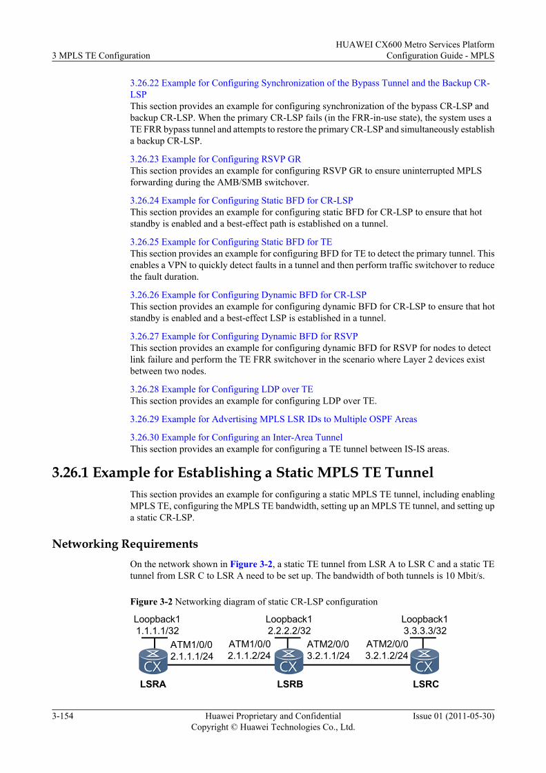
3.26.22 Example for Configuring Synchronization of the Bypass Tunnel and the Backup CR-LSPThis section provides an example for configuring synchronization of the bypass CR-LSP andbackup CR-LSP. When the primary CR-LSP fails (in the FRR-in-use state), the system uses aTE FRR bypass tunnel and attempts to restore the primary CR-LSP and simultaneously establisha backup CR-LSP.
3.26.23 Example for Configuring RSVP GRThis section provides an example for configuring RSVP GR to ensure uninterrupted MPLSforwarding during the AMB/SMB switchover.
3.26.24 Example for Configuring Static BFD for CR-LSPThis section provides an example for configuring static BFD for CR-LSP to ensure that hotstandby is enabled and a best-effect path is established on a tunnel.
3.26.25 Example for Configuring Static BFD for TEThis section provides an example for configuring BFD for TE to detect the primary tunnel. Thisenables a VPN to quickly detect faults in a tunnel and then perform traffic switchover to reducethe fault duration.
3.26.26 Example for Configuring Dynamic BFD for CR-LSPThis section provides an example for configuring dynamic BFD for CR-LSP to ensure that hotstandby is enabled and a best-effect LSP is established in a tunnel.
3.26.27 Example for Configuring Dynamic BFD for RSVPThis section provides an example for configuring dynamic BFD for RSVP for nodes to detectlink failure and perform the TE FRR switchover in the scenario where Layer 2 devices existbetween two nodes.
3.26.28 Example for Configuring LDP over TEThis section provides an example for configuring LDP over TE.
3.26.29 Example for Advertising MPLS LSR IDs to Multiple OSPF Areas
3.26.30 Example for Configuring an Inter-Area TunnelThis section provides an example for configuring a TE tunnel between IS-IS areas.
3.26.1 Example for Establishing a Static MPLS TE TunnelThis section provides an example for configuring a static MPLS TE tunnel, including enablingMPLS TE, configuring the MPLS TE bandwidth, setting up an MPLS TE tunnel, and setting upa static CR-LSP.
Networking RequirementsOn the network shown in Figure 3-2, a static TE tunnel from LSR A to LSR C and a static TEtunnel from LSR C to LSR A need to be set up. The bandwidth of both tunnels is 10 Mbit/s.
Figure 3-2 Networking diagram of static CR-LSP configuration
LSRB
ATM1/0/02.1.1.1/24
ATM1/0/02.1.1.2/24
LSRA LSRC
ATM2/0/03.2.1.1/24
ATM2/0/03.2.1.2/24
Loopback11.1.1.1/32
Loopback12.2.2.2/32
Loopback13.3.3.3/32
3 MPLS TE ConfigurationHUAWEI CX600 Metro Services Platform
Configuration Guide - MPLS
3-154 Huawei Proprietary and ConfidentialCopyright © Huawei Technologies Co., Ltd.
Issue 01 (2011-05-30)
Configuration RoadmapThe configuration roadmap is as follows:
1. Assign an IP address to each interface on each LSR, configure the loopback address as theMPLS LSR ID, and configure OSPF to advertise the route to the network segmentconnecting to each interface and LSR ID.
2. Configure the LSR ID and globally enable MPLS and MPLS TE on each node and interface.3. Set the type of the OSPF network to P2P and run the map ip default broadcast command
to configure the broadcast interface because the ATM interface is used.4. Configure the maximum reservable bandwidth and BC0 bandwidth for the link on each
outgoing interface of each LSR along the tunnel (assume the tunnel obtains bandwidth fromBC0).
5. Create a tunnel interface on the ingress and specify the IP address of the tunnel, tunnelprotocol, destination address, tunnel ID, and the signaling protocol used for establishingthe tunnel.
6. Configure a static LSP associated with the tunnel, and specify the outgoing label and next-hop address on the ingress, the incoming interface, next-hop address, and outgoing labelon the transit node, and the incoming label and incoming interface on the egress to set upthe LSP.
NOTE
l The outgoing label of each node is the incoming label of the next node.
l When running the static-cr-lsp ingress { tunnel-interface tunnel tunnel-number | tunnel-name }destination destination-address { nexthop next-hop-address | outgoing-interface interface-typeinterface-number } out-label out-label-value [ bandwidth [ ct0 | ct1 ] bandwidth ] command toconfigure the ingress of a CR-LSP, note that tunnel-name must be the same as the tunnel name createdby using the interface tunnel interface -number command. tunnel-name is a case-sensitive characterstring in which spaces are not supported. For example, the name of the tunnel created by using theinterface tunnel 2/0/0 command is Tunnel2/0/0. In this case, the parameter of the static CR-LSP onthe ingress is Tunnel2/0/0, ensuring that the tunnel is successfully created. This restriction does notapply to transit nodes or egresses.
Data PreparationTo complete the configuration, you need the following data:
l OSPF process ID and area ID of each LSRl Tunnel interface names, tunnel interface IP addresses, destination addresses, tunnel IDs,
and tunnel signaling protocol (CR-Static) on LSR A and LSR Cl The maximum reservable bandwidth and BC bandwidth of linksl Next-hop address and outgoing label of the ingress on the static CR-LSPl Incoming interface, next-hop address, and outgoing label of the transit node on the static
CR-LSPl Incoming interface of the egress on the static CR-LSP
Procedure
Step 1 Configure the IP address of each interface and a routing protocol.
HUAWEI CX600 Metro Services PlatformConfiguration Guide - MPLS 3 MPLS TE Configuration
Issue 01 (2011-05-30) Huawei Proprietary and ConfidentialCopyright © Huawei Technologies Co., Ltd.
3-155
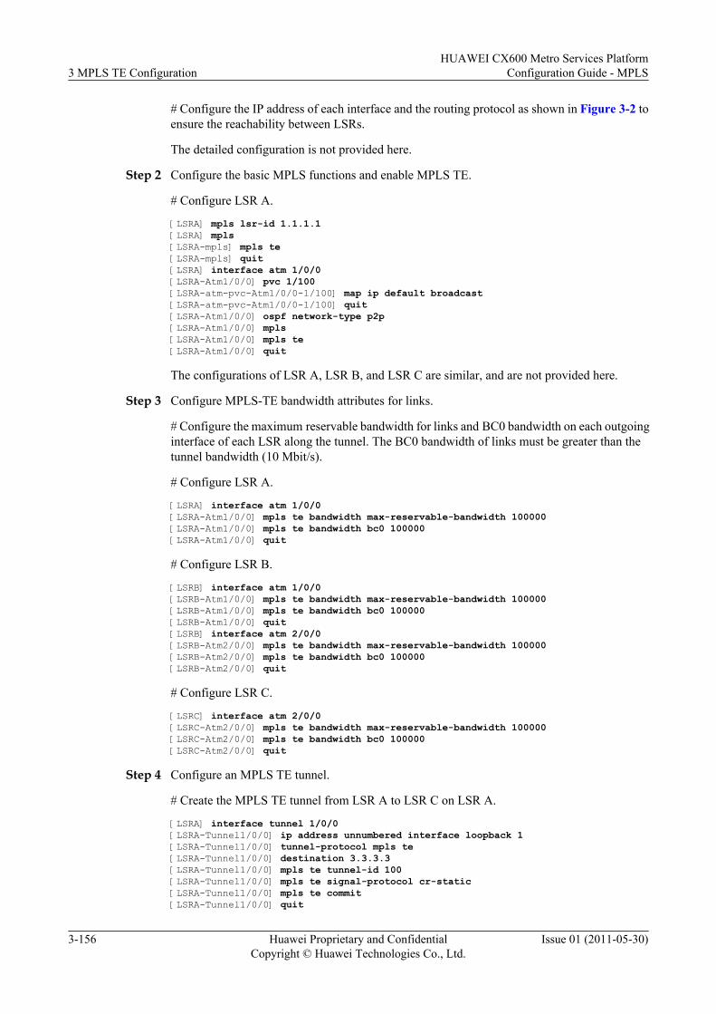
# Configure the IP address of each interface and the routing protocol as shown in Figure 3-2 toensure the reachability between LSRs.
The detailed configuration is not provided here.
Step 2 Configure the basic MPLS functions and enable MPLS TE.
# Configure LSR A.
[LSRA] mpls lsr-id 1.1.1.1[LSRA] mpls[LSRA-mpls] mpls te[LSRA-mpls] quit[LSRA] interface atm 1/0/0[LSRA-Atm1/0/0] pvc 1/100[LSRA-atm-pvc-Atm1/0/0-1/100] map ip default broadcast[LSRA-atm-pvc-Atm1/0/0-1/100] quit[LSRA-Atm1/0/0] ospf network-type p2p[LSRA-Atm1/0/0] mpls[LSRA-Atm1/0/0] mpls te[LSRA-Atm1/0/0] quit
The configurations of LSR A, LSR B, and LSR C are similar, and are not provided here.
Step 3 Configure MPLS-TE bandwidth attributes for links.
# Configure the maximum reservable bandwidth for links and BC0 bandwidth on each outgoinginterface of each LSR along the tunnel. The BC0 bandwidth of links must be greater than thetunnel bandwidth (10 Mbit/s).
# Configure LSR A.
[LSRA] interface atm 1/0/0[LSRA-Atm1/0/0] mpls te bandwidth max-reservable-bandwidth 100000[LSRA-Atm1/0/0] mpls te bandwidth bc0 100000[LSRA-Atm1/0/0] quit
# Configure LSR B.
[LSRB] interface atm 1/0/0[LSRB-Atm1/0/0] mpls te bandwidth max-reservable-bandwidth 100000[LSRB-Atm1/0/0] mpls te bandwidth bc0 100000[LSRB-Atm1/0/0] quit[LSRB] interface atm 2/0/0[LSRB-Atm2/0/0] mpls te bandwidth max-reservable-bandwidth 100000[LSRB-Atm2/0/0] mpls te bandwidth bc0 100000[LSRB-Atm2/0/0] quit
# Configure LSR C.
[LSRC] interface atm 2/0/0[LSRC-Atm2/0/0] mpls te bandwidth max-reservable-bandwidth 100000[LSRC-Atm2/0/0] mpls te bandwidth bc0 100000[LSRC-Atm2/0/0] quit
Step 4 Configure an MPLS TE tunnel.
# Create the MPLS TE tunnel from LSR A to LSR C on LSR A.
[LSRA] interface tunnel 1/0/0[LSRA-Tunnel1/0/0] ip address unnumbered interface loopback 1[LSRA-Tunnel1/0/0] tunnel-protocol mpls te[LSRA-Tunnel1/0/0] destination 3.3.3.3[LSRA-Tunnel1/0/0] mpls te tunnel-id 100[LSRA-Tunnel1/0/0] mpls te signal-protocol cr-static[LSRA-Tunnel1/0/0] mpls te commit[LSRA-Tunnel1/0/0] quit
3 MPLS TE ConfigurationHUAWEI CX600 Metro Services Platform
Configuration Guide - MPLS
3-156 Huawei Proprietary and ConfidentialCopyright © Huawei Technologies Co., Ltd.
Issue 01 (2011-05-30)
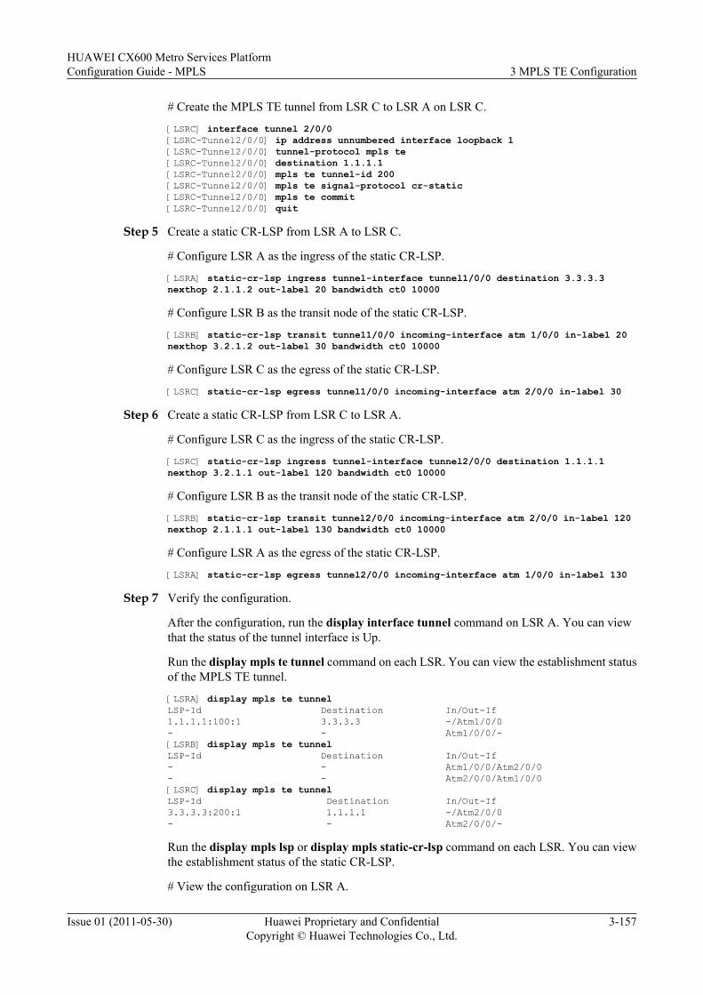
# Create the MPLS TE tunnel from LSR C to LSR A on LSR C.
[LSRC] interface tunnel 2/0/0[LSRC-Tunnel2/0/0] ip address unnumbered interface loopback 1[LSRC-Tunnel2/0/0] tunnel-protocol mpls te[LSRC-Tunnel2/0/0] destination 1.1.1.1[LSRC-Tunnel2/0/0] mpls te tunnel-id 200[LSRC-Tunnel2/0/0] mpls te signal-protocol cr-static[LSRC-Tunnel2/0/0] mpls te commit[LSRC-Tunnel2/0/0] quit
Step 5 Create a static CR-LSP from LSR A to LSR C.
# Configure LSR A as the ingress of the static CR-LSP.
[LSRA] static-cr-lsp ingress tunnel-interface tunnel1/0/0 destination 3.3.3.3 nexthop 2.1.1.2 out-label 20 bandwidth ct0 10000
# Configure LSR B as the transit node of the static CR-LSP.
[LSRB] static-cr-lsp transit tunnel1/0/0 incoming-interface atm 1/0/0 in-label 20 nexthop 3.2.1.2 out-label 30 bandwidth ct0 10000
# Configure LSR C as the egress of the static CR-LSP.
[LSRC] static-cr-lsp egress tunnel1/0/0 incoming-interface atm 2/0/0 in-label 30
Step 6 Create a static CR-LSP from LSR C to LSR A.
# Configure LSR C as the ingress of the static CR-LSP.
[LSRC] static-cr-lsp ingress tunnel-interface tunnel2/0/0 destination 1.1.1.1 nexthop 3.2.1.1 out-label 120 bandwidth ct0 10000
# Configure LSR B as the transit node of the static CR-LSP.
[LSRB] static-cr-lsp transit tunnel2/0/0 incoming-interface atm 2/0/0 in-label 120 nexthop 2.1.1.1 out-label 130 bandwidth ct0 10000
# Configure LSR A as the egress of the static CR-LSP.
[LSRA] static-cr-lsp egress tunnel2/0/0 incoming-interface atm 1/0/0 in-label 130
Step 7 Verify the configuration.
After the configuration, run the display interface tunnel command on LSR A. You can viewthat the status of the tunnel interface is Up.
Run the display mpls te tunnel command on each LSR. You can view the establishment statusof the MPLS TE tunnel.
[LSRA] display mpls te tunnelLSP-Id Destination In/Out-If1.1.1.1:100:1 3.3.3.3 -/Atm1/0/0- - Atm1/0/0/-[LSRB] display mpls te tunnelLSP-Id Destination In/Out-If- - Atm1/0/0/Atm2/0/0- - Atm2/0/0/Atm1/0/0[LSRC] display mpls te tunnelLSP-Id Destination In/Out-If3.3.3.3:200:1 1.1.1.1 -/Atm2/0/0- - Atm2/0/0/-
Run the display mpls lsp or display mpls static-cr-lsp command on each LSR. You can viewthe establishment status of the static CR-LSP.
# View the configuration on LSR A.
HUAWEI CX600 Metro Services PlatformConfiguration Guide - MPLS 3 MPLS TE Configuration
Issue 01 (2011-05-30) Huawei Proprietary and ConfidentialCopyright © Huawei Technologies Co., Ltd.
3-157
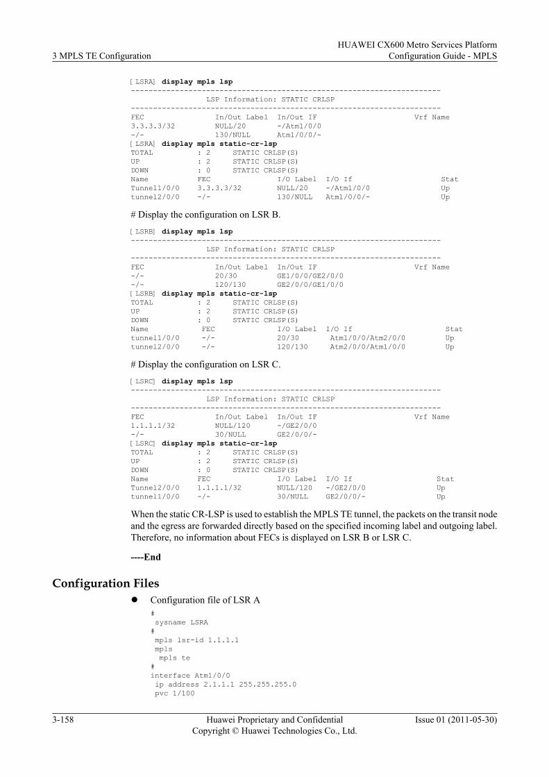
[LSRA] display mpls lsp---------------------------------------------------------------------- LSP Information: STATIC CRLSP----------------------------------------------------------------------FEC In/Out Label In/Out IF Vrf Name3.3.3.3/32 NULL/20 -/Atm1/0/0-/- 130/NULL Atm1/0/0/-[LSRA] display mpls static-cr-lspTOTAL : 2 STATIC CRLSP(S)UP : 2 STATIC CRLSP(S)DOWN : 0 STATIC CRLSP(S)Name FEC I/O Label I/O If StatTunnel1/0/0 3.3.3.3/32 NULL/20 -/Atm1/0/0 Uptunnel2/0/0 -/- 130/NULL Atm1/0/0/- Up
# Display the configuration on LSR B.
[LSRB] display mpls lsp---------------------------------------------------------------------- LSP Information: STATIC CRLSP----------------------------------------------------------------------FEC In/Out Label In/Out IF Vrf Name-/- 20/30 GE1/0/0/GE2/0/0-/- 120/130 GE2/0/0/GE1/0/0[LSRB] display mpls static-cr-lspTOTAL : 2 STATIC CRLSP(S)UP : 2 STATIC CRLSP(S)DOWN : 0 STATIC CRLSP(S)Name FEC I/O Label I/O If Stattunnel1/0/0 -/- 20/30 Atm1/0/0/Atm2/0/0 Uptunnel2/0/0 -/- 120/130 Atm2/0/0/Atm1/0/0 Up
# Display the configuration on LSR C.
[LSRC] display mpls lsp---------------------------------------------------------------------- LSP Information: STATIC CRLSP----------------------------------------------------------------------FEC In/Out Label In/Out IF Vrf Name1.1.1.1/32 NULL/120 -/GE2/0/0-/- 30/NULL GE2/0/0/-[LSRC] display mpls static-cr-lspTOTAL : 2 STATIC CRLSP(S)UP : 2 STATIC CRLSP(S)DOWN : 0 STATIC CRLSP(S)Name FEC I/O Label I/O If StatTunnel2/0/0 1.1.1.1/32 NULL/120 -/GE2/0/0 Uptunnel1/0/0 -/- 30/NULL GE2/0/0/- Up
When the static CR-LSP is used to establish the MPLS TE tunnel, the packets on the transit nodeand the egress are forwarded directly based on the specified incoming label and outgoing label.Therefore, no information about FECs is displayed on LSR B or LSR C.
----End
Configuration Filesl Configuration file of LSR A
# sysname LSRA# mpls lsr-id 1.1.1.1 mpls mpls te#interface Atm1/0/0 ip address 2.1.1.1 255.255.255.0 pvc 1/100
3 MPLS TE ConfigurationHUAWEI CX600 Metro Services Platform
Configuration Guide - MPLS
3-158 Huawei Proprietary and ConfidentialCopyright © Huawei Technologies Co., Ltd.
Issue 01 (2011-05-30)
map ip default broadcast ospf network-type p2p mpls mpls te mpls te bandwidth max-reservable-bandwidth 100000mpls te bandwidth bc0 100000#interface LoopBack1 ip address 1.1.1.1 255.255.255.255#interface Tunnel1/0/0 ip address unnumbered interface LoopBack1 tunnel-protocol mpls te destination 3.3.3.3 mpls te tunnel-id 100 mpls te signal-protocol cr-static mpls te commit#ospf 1 area 0.0.0.0 network 2.1.1.0 0.0.0.255 network 1.1.1.1 0.0.0.0#static-cr-lsp ingress tunnel-interface Tunnel1/0/0 destination 3.3.3.3 nexthop 2.1.1.2 out-label 20 bandwidth ct0 10000static-cr-lsp egress tunnel2/0/0 incoming-interface Atm1/0/0 in-label 130#return
l Configuration file of LSR B# sysname LSRB# mpls lsr-id 2.2.2.2 mpls mpls te#interface Atm1/0/0 ip address 2.1.1.2 255.255.255.0 pvc 1/100 map ip default broadcast ospf network-type p2p mpls mpls te mpls te bandwidth max-reservable-bandwidth 100000mpls te bandwidth bc0 100000#interface Atm2/0/0 ip address 3.2.1.1 255.255.255.0 pvc 1/100 map ip default broadcast ospf network-type p2p mpls mpls te mpls te bandwidth max-reservable-bandwidth 100000mpls te bandwidth bc0 100000#interface LoopBack1 ip address 2.2.2.2 255.255.255.255#ospf 1 area 0.0.0.0 network 2.1.1.0 0.0.0.255 network 3.2.1.0 0.0.0.255 network 2.2.2.2 0.0.0.0#static-cr-lsp transit tunnel1/0/0 incoming-interface Atm1/0/0 in-label 20 nexthop 3.2.1.2 out-label 30 bandwidth ct0 10000static-cr-lsp transit tunnel2/0/0 incoming-interface Atm2/0/0 in-label 120 nexthop 2.1.1.1 out-label 130 bandwidth ct0 10000
HUAWEI CX600 Metro Services PlatformConfiguration Guide - MPLS 3 MPLS TE Configuration
Issue 01 (2011-05-30) Huawei Proprietary and ConfidentialCopyright © Huawei Technologies Co., Ltd.
3-159
#return
l Configuration file of LSR C# sysname LSRC# mpls lsr-id 3.3.3.3 mpls mpls te#interface Atm2/0/0 ip address 3.2.1.2 255.255.255.0 pvc 1/100 map ip default broadcast ospf network-type p2p mpls mpls te mpls te bandwidth max-reservable-bandwidth 100000mpls te bandwidth bc0 100000#interface LoopBack1 ip address 3.3.3.3 255.255.255.255#interface Tunnel2/0/0 ip address unnumbered interface LoopBack1 tunnel-protocol mpls te destination 1.1.1.1 mpls te signal-protocol cr-static mpls te tunnel-id 200 mpls te commit#ospf 1 area 0.0.0.0 network 3.2.1.0 0.0.0.255 network 3.3.3.3 0.0.0.0#static-cr-lsp ingress tunnel-interface Tunnel2/0/0 destination 1.1.1.1 nexthop 3.2.1.1 out-label 120 bandwidth ct0 10000static-cr-lsp egress tunnel1/0/0 incoming-interface Atm2/0/0 in-label 30#return
3.26.2 Example for Configuring a Static Bidirectional Co-routed LSPThis section uses an example to describe the procedure for configuring a static bidirectional co-routed LSP, including how to enable MPLS TE, configure MPLS TE bandwidth attributes,configure an MPLS TE tunnel, and create a static bidirectional co-routed LSP.
ContextMPLS-TP is widely used on transport networks. Although MPLS-TP supports OAM, OAMitself only supports the network element-level management system, which cannot meet therequirements for network management over public telecommunication networks. MPLS-TPOAM supporting static bidirectional co-routed LSP is an effective operation and managementmethod and can detect, identify, and locate faults in the MPLS-TP user plane.
This example only describes the configuration procedure for a static bidirectional co-routed LSP.For information about MPLS-TP OAM, see the description in Configuring MPLS-TP OAM.
As shown in Figure 3-3, a static bidirectional co-routed LSP originates from LSR A andterminates on LSR C. OAM PDUs travel through this LSP and any transit node can send aresponse along the same path in the opposite direction. The links for the static bidirectional co-routed LSP between LSR A and LSR C has the bandwidth of 10 Mbit/s.
3 MPLS TE ConfigurationHUAWEI CX600 Metro Services Platform
Configuration Guide - MPLS
3-160 Huawei Proprietary and ConfidentialCopyright © Huawei Technologies Co., Ltd.
Issue 01 (2011-05-30)
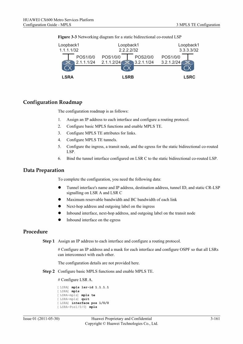
Figure 3-3 Networking diagram for a static bidirectional co-routed LSP
LSRA LSRB LSRC
Loopback11.1.1.1/32
Loopback12.2.2.2/32
Loopback13.3.3.3/32
POS1/0/02.1.1.1/24
POS1/0/02.1.1.2/24
POS2/0/03.2.1.1/24
POS1/0/03.2.1.2/24
Configuration RoadmapThe configuration roadmap is as follows:
1. Assign an IP address to each interface and configure a routing protocol.2. Configure basic MPLS functions and enable MPLS TE.3. Configure MPLS TE attributes for links.4. Configure MPLS TE tunnels.5. Configure the ingress, a transit node, and the egress for the static bidirectional co-routed
LSP.6. Bind the tunnel interface configured on LSR C to the static bidirectional co-routed LSP.
Data PreparationTo complete the configuration, you need the following data:
l Tunnel interface's name and IP address, destination address, tunnel ID, and static CR-LSPsignalling on LSR A and LSR C
l Maximum reservable bandwidth and BC bandwidth of each linkl Next-hop address and outgoing label on the ingressl Inbound interface, next-hop address, and outgoing label on the transit nodel Inbound interface on the egress
Procedure
Step 1 Assign an IP address to each interface and configure a routing protocol.
# Configure an IP address and a mask for each interface and configure OSPF so that all LSRscan interconnect with each other.
The configuration details are not provided here.
Step 2 Configure basic MPLS functions and enable MPLS TE.
# Configure LSR A.
[LSRA] mpls lsr-id 1.1.1.1[LSRA] mpls[LSRA-mpls] mpls te[LSRA-mpls] quit[LSRA] interface pos 1/0/0[LSRA-Pos1/0/0] mpls
HUAWEI CX600 Metro Services PlatformConfiguration Guide - MPLS 3 MPLS TE Configuration
Issue 01 (2011-05-30) Huawei Proprietary and ConfidentialCopyright © Huawei Technologies Co., Ltd.
3-161
[LSRA-Pos1/0/0] mpls te[LSRA-Pos1/0/0] quit
The configurations on LSR B and LSR C are similar to the configuration on LSR A.
Step 3 Configure MPLS TE attributes for links.
# Configure the maximum reservable bandwidth and BC0 bandwidth for the link on the outboundinterface of each LSR. The BC0 bandwidth of links must be greater than the tunnel bandwidth(10 Mbit/s).
# Configure LSR A.
[LSRA] interface pos 1/0/0[LSRA-Pos1/0/0] mpls te bandwidth max-reservable-bandwidth 100000[LSRA-Pos1/0/0] mpls te bandwidth bc0 100000[LSRA-Pos1/0/0] quit
# Configure LSR B.
[LSRB] interface pos 1/0/0[LSRB-Pos1/0/0] mpls te bandwidth max-reservable-bandwidth 100000[LSRB-Pos1/0/0] mpls te bandwidth bc0 100000[LSRB-Pos1/0/0] quit[LSRB] interface pos 2/0/0[LSRB-Pos2/0/0] mpls te bandwidth max-reservable-bandwidth 100000[LSRB-Pos2/0/0] mpls te bandwidth bc0 100000[LSRB-Pos2/0/0] quit
# Configure LSR C.
[LSRC] interface pos 2/0/0[LSRC-Pos2/0/0] mpls te bandwidth max-reservable-bandwidth 100000[LSRC-Pos2/0/0] mpls te bandwidth bc0 100000[LSRC-Pos2/0/0] quit
Step 4 Configure MPLS TE tunnel interfaces.
# Create an MPLS TE tunnel on LSR A to reach LSR C.
[LSRA] interface tunnel 1/0/0[LSRA-Tunnel1/0/0] ip address unnumbered interface loopback 1[LSRA-Tunnel1/0/0] tunnel-protocol mpls te[LSRA-Tunnel1/0/0] destination 3.3.3.3[LSRA-Tunnel1/0/0] mpls te tunnel-id 100[LSRA-Tunnel1/0/0] mpls te signal-protocol cr-static[LSRA-Tunnel1/0/0] mpls te bidirectional[LSRA-Tunnel1/0/0] mpls te commit[LSRA-Tunnel1/0/0] quit
# Create an MPLS TE tunnel on LSR C to reach LSR A.
[LSRC] interface tunnel 2/0/0[LSRC-Tunnel2/0/0] ip address unnumbered interface loopback 1[LSRC-Tunnel2/0/0] tunnel-protocol mpls te[LSRC-Tunnel2/0/0] destination 1.1.1.1[LSRC-Tunnel2/0/0] mpls te tunnel-id 200[LSRC-Tunnel2/0/0] mpls te signal-protocol cr-static[LSRC-Tunnel2/0/0] mpls te commit[LSRC-Tunnel2/0/0] quit
Step 5 Configure the ingress, a transit node, and the egress of the static bidirectional co-routed LSP.
# Configure LSR A as the ingress.[LSRA] bidirectional static-cr-lsp ingress Tunnel/0/0[LSRA-bi-static-ingress-Tunnel0/0/1] forward nexthop 2.1.1.2 out-label 20 bandwidth ct0 10000[LSRA-bi-static-ingress-Tunnel0/0/1] backward in-label 20
3 MPLS TE ConfigurationHUAWEI CX600 Metro Services Platform
Configuration Guide - MPLS
3-162 Huawei Proprietary and ConfidentialCopyright © Huawei Technologies Co., Ltd.
Issue 01 (2011-05-30)
# Configure LSR B as a transit node.[LSRB]bidirectional static-cr-lsp transit lsp1[LSRB-bi-static-transit-lsp1] forward in-label 20 nexthop 3.2.1.2 out-label 40 bandwidth ct0 10000[LSRB-bi-static-transit-lsp1] backward in-label 10 nexthop 2.1.1.1 out-label 20 bandwidth ct0 10000
# Configure LSR C as the egress.[LSRC] bidirectional static-cr-lsp egress lsp1[LSRC-bi-static-egress-lsp1] forward in-label 40 lsrid 1.1.1.1 tunnel-id 100[LSRC-bi-static-egress-lsp1] backward nexthop 3.2.1.1 out-label 10 bandwidth ct0 10000
Step 6 Bind the tunnel interface on LSR C to the static bidirectional co-routed LSP.
[LSRC] interface Tunnel1/0/0[LSRC-Tunnel1/0/0] mpls te passive-tunnel[LSRC-Tunnel1/0/0] mpls te binding bidirectional static-cr-lsp egress Tunnel1/0/0[LSRC-Tunnel1/0/0] mpls te commit[LSRC-Tunnel1/0/0] quit
Step 7 Verify the configuration.
After completing the configuration, run the display interface tunnel command on LSRA. Youcan see that the tunnel interface is Up.
Run the display mpls te tunnel command on each LSR to check that MPLS TE tunnels are setup.
# Check the configuration results on LSR A.
[LSRA] display mpls te tunnelLSP-Id Destination In/Out-If1.1.1.1:100:1 3.3.3.3 -/Pos1/0/0- - Pos1/0/0/-
# Check the configuration results on LSR A.
[LSRB] display mpls te tunnelLSP-Id Destination In/Out-If- - Pos1/0/0/Pos2/0/0- - Pos2/0/0/Pos1/0/0
# Check the configuration results on LSR A.
[LSRC] display mpls te tunnelLSP-Id Destination In/Out-If3.3.3.3:200:1 1.1.1.1 -/Pos2/0/0- - Pos2/0/0/-
Run the display mpls te bidirectional static-cr-lsp command on each LSR. Information aboutthe static bidirectional co-routed LSP is displayed.
# Check the configuration results on LSR A.
[LSRA] display mpls te bidirectional static-cr-lspTOTAL : 1 STATIC CRLSP(S)UP : 1 STATIC CRLSP(S)DOWN : 0 STATIC CRLSP(S)Name FEC I/O Label I/O If StatTunnel1/0/0 2.2.2.2/32 NULL/20 -/Pos1/0/0 20/NULL Pos1/0/0- Up
# Check the configuration results on LSR A.
[LSRB] display mpls te bidirectional static-cr-lspTOTAL : 1 STATIC CRLSP(S)UP : 1 STATIC CRLSP(S)
HUAWEI CX600 Metro Services PlatformConfiguration Guide - MPLS 3 MPLS TE Configuration
Issue 01 (2011-05-30) Huawei Proprietary and ConfidentialCopyright © Huawei Technologies Co., Ltd.
3-163
DOWN : 0 STATIC CRLSP(S)Name FEC I/O Label I/O If Statlsp1 -/- 20/40 -/Pos1/0/0 10/20 Pos2/0/0- Up
# Check the configuration results on LSR A.
[LSRC] display mpls te bidirectional static-cr-lspTOTAL : 1 STATIC CRLSP(S)UP : 1 STATIC CRLSP(S)DOWN : 0 STATIC CRLSP(S)Name FEC I/O Label I/O If Statlsp1 -/32 20/NULL Pos1/0/0/- NULL/20 -/Pos1/0/0 Up
When a static bidirectional co-routed LSP is established, packets on a transit node (LSR B) andthe egress (LSR C) are forwarded directly based on the incoming and outgoing labels specifiedon the nodes. Therefore, the FEC-relevant contents are empty in the display on LSR B and LSRC.
After completing the configurations, run the ping command on LSR A. The static bidirectionalco-routed LSP is reachable.[LSRA] ping lsp te Tunnel 1/0/0 LSP PING FEC: TE TUNNEL IPV4 SESSION QUERY Tunnel1/0/0 : 100 data bytes, press CTRL_C to break Reply from 3.3.3.3: bytes=100 Sequence=1 time = 110 ms Reply from 3.3.3.3: bytes=100 Sequence=2 time = 70 ms Reply from 3.3.3.3: bytes=100 Sequence=3 time = 60 ms Reply from 3.3.3.3: bytes=100 Sequence=4 time = 80 ms Reply from 3.3.3.3: bytes=100 Sequence=5 time = 60 ms
--- FEC: TE TUNNEL IPV4 SESSION QUERY Tunnel1/0/0 ping statistics --- 5 packet(s) transmitted 5 packet(s) received 0.00% packet loss round-trip min/avg/max = 60/76/110 ms
----End
Configuration Filesl Configuration file of LSR A
# sysname LSRA# mpls lsr-id 1.1.1.1 mpls mpls te# bidirectional static-cr-lsp ingress Tunnel1/0/0 forward nexthop 2.1.1.2 out-label 20 bandwidth ct0 10000 backward in-label 20#interface Pos1/0/0 undo shutdown ip address 2.1.1.1 255.255.255.0 mpls mpls te mpls te bandwidth max-reservable-bandwidth 100000 mpls te bandwidth bc0 100000#interface LoopBack1 ip address 1.1.1.1 255.255.255.255#interface Tunnel1/0/0 ip address unnumbered interface LoopBack1 tunnel-protocol mpls te
3 MPLS TE ConfigurationHUAWEI CX600 Metro Services Platform
Configuration Guide - MPLS
3-164 Huawei Proprietary and ConfidentialCopyright © Huawei Technologies Co., Ltd.
Issue 01 (2011-05-30)
destination 3.3.3.3 mpls te signal-protocol cr-static mpls te tunnel-id 100 mpls te bidirectional mpls te commit# ip route-static 2.2.2.2 255.255.255.255 2.1.1.2 ip route-static 3.3.3.3 255.255.255.255 2.1.1.2#return
l Configuration file of LSR B# sysname LSRB# mpls lsr-id 2.2.2.2 mpls mpls te# bidirectional static-cr-lsp transit lsp1 forward in-label 20 nexthop 3.2.1.2 out-label 40 bandwidth ct0 10000 backward in-label 10 nexthop 2.1.1.1 out-label 20 bandwidth ct0 10000#interface Pos1/0/0 undo shutdown ip address 2.1.1.2 255.255.255.0 mpls mpls te mpls te bandwidth max-reservable-bandwidth 100000 mpls te bandwidth bc0 100000#interface Pos2/0/0 undo shutdown ip address 3.2.1.1 255.255.255.0 mpls mpls te mpls te bandwidth max-reservable-bandwidth 100000 mpls te bandwidth bc0 100000#interface LoopBack1 ip address 2.2.2.2 255.255.255.255# ip route-static 1.1.1.1 255.255.255.255 2.1.1.1 ip route-static 3.3.3.3 255.255.255.255 3.2.1.2#return
l Configuration file of LSR C# sysname LSRC# mpls lsr-id 3.3.3.3 mpls mpls te# bidirectional static-cr-lsp egress lsp1 forward in-label 40 lsrid 1.1.1.1 tunnel-id 100 backward nexthop 3.2.1.1 out-label 10 bandwidth ct0 10000#interface Pos1/0/0 undo shutdown ip address 3.2.1.2 255.255.255.0 mpls mpls te mpls te bandwidth max-reservable-bandwidth 100000 mpls te bandwidth bc0 100000#interface LoopBack1 ip address 3.3.3.3 255.255.255.255#
HUAWEI CX600 Metro Services PlatformConfiguration Guide - MPLS 3 MPLS TE Configuration
Issue 01 (2011-05-30) Huawei Proprietary and ConfidentialCopyright © Huawei Technologies Co., Ltd.
3-165
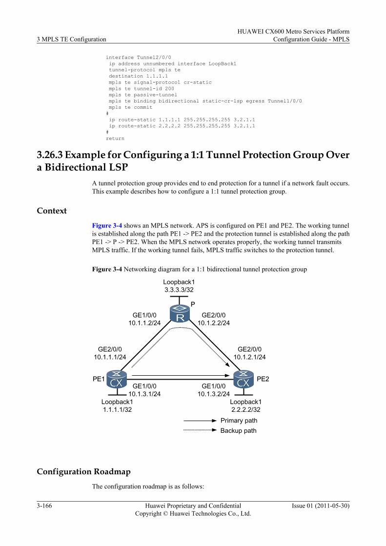
interface Tunnel2/0/0 ip address unnumbered interface LoopBack1 tunnel-protocol mpls te destination 1.1.1.1 mpls te signal-protocol cr-static mpls te tunnel-id 200 mpls te passive-tunnel mpls te binding bidirectional static-cr-lsp egress Tunnel1/0/0 mpls te commit# ip route-static 1.1.1.1 255.255.255.255 3.2.1.1 ip route-static 2.2.2.2 255.255.255.255 3.2.1.1#return
3.26.3 Example for Configuring a 1:1 Tunnel Protection Group Overa Bidirectional LSP
A tunnel protection group provides end to end protection for a tunnel if a network fault occurs.This example describes how to configure a 1:1 tunnel protection group.
ContextFigure 3-4 shows an MPLS network. APS is configured on PE1 and PE2. The working tunnelis established along the path PE1 -> PE2 and the protection tunnel is established along the pathPE1 -> P -> PE2. When the MPLS network operates properly, the working tunnel transmitsMPLS traffic. If the working tunnel fails, MPLS traffic switches to the protection tunnel.
Figure 3-4 Networking diagram for a 1:1 bidirectional tunnel protection group
PE1 PE2
P
Loopback11.1.1.1/32
Loopback12.2.2.2/32
Loopback13.3.3.3/32
GE1/0/010.1.1.2/24
GE2/0/010.1.2.2/24
GE1/0/010.1.3.1/24
GE1/0/010.1.3.2/24
GE2/0/010.1.1.1/24
GE2/0/010.1.2.1/24
Primary pathBackup path
Configuration RoadmapThe configuration roadmap is as follows:
3 MPLS TE ConfigurationHUAWEI CX600 Metro Services Platform
Configuration Guide - MPLS
3-166 Huawei Proprietary and ConfidentialCopyright © Huawei Technologies Co., Ltd.
Issue 01 (2011-05-30)
1. Assign an IP address to each interface and configure a routing protocol.2. Configure basic MPLS functions and enable MPLS TE.3. Configure MPLS TE bandwidth attributes for links.4. Configure the ingress, a transit node, and the egress for the static bidirectional co-routed
LSP of primary tunnel.5. Configure the ingress, a transit node, and the egress for the static bidirectional co-routed
LSP of protect tunnel.6. Configure MPLS TE tunnels.7. Configure APS.
Data PreparationTo complete the configuration, you need the following data:
l Tunnel interface's name and IP address, destination address, tunnel ID, and static CR-LSPsignaling on PE1 and PE2
l Maximum reservable bandwidth and BC bandwidth of each linkl Next-hop address and outgoing label on the ingressl Inbound interface, next-hop address, and outgoing label on the transit nodel Inbound interface on the egress
Procedure
Step 1 Assign an IP address to each interface and configure a routing protocol.
Configure an IP address and a mask for each interface and configure OSPF to allow all LSRs tointerconnect with each other.
The configuration details are not provided here.
Step 2 Configure basic MPLS functions and enable MPLS TE.
# Configure PE1.
[PE1] mpls lsr-id 1.1.1.1[PE1] mpls[PE1-mpls] mpls te[PE1-mpls] quit[PE1] interface GigabitEthernet 1/0/0[PE1-GigabitEthernet1/0/0] mpls[PE1-GigabitEthernet1/0/0] mpls te[PE1-GigabitEthernet1/0/0] quit[PE1] interface GigabitEthernet 2/0/0[PE1-GigabitEthernet2/0/0] mpls[PE1-GigabitEthernet2/0/0] mpls te[PE1-GigabitEthernet2/0/0] quit
The configurations on PE2 and P are similar to the configuration on PE1.
Step 3 Configure MPLS TE attributes for links.
# Configure the maximum reservable bandwidth and BC0 bandwidth for the link on the outboundinterface of each node. The BC0 bandwidth of links must be greater than the tunnel bandwidth(10 Mbit/s).
# Configure PE1.
HUAWEI CX600 Metro Services PlatformConfiguration Guide - MPLS 3 MPLS TE Configuration
Issue 01 (2011-05-30) Huawei Proprietary and ConfidentialCopyright © Huawei Technologies Co., Ltd.
3-167
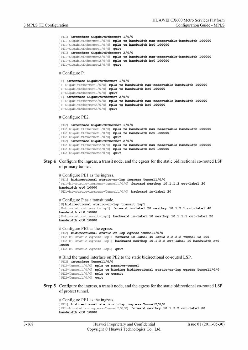
[PE1] interface GigabitEthernet 1/0/0[PE1-GigabitEthernet1/0/0] mpls te bandwidth max-reservable-bandwidth 100000[PE1-GigabitEthernet1/0/0] mpls te bandwidth bc0 100000[PE1-GigabitEthernet1/0/0] quit[PE1] interface GigabitEthernet 2/0/0[PE1-GigabitEthernet2/0/0] mpls te bandwidth max-reservable-bandwidth 100000[PE1-GigabitEthernet2/0/0] mpls te bandwidth bc0 100000[PE1-GigabitEthernet2/0/0] quit
# Configure P.
[P] interface GigabitEthernet 1/0/0[P-GigabitEthernet1/0/0] mpls te bandwidth max-reservable-bandwidth 100000[P-GigabitEthernet1/0/0] mpls te bandwidth bc0 100000[P-GigabitEthernet1/0/0] quit[P] interface GigabitEthernet 2/0/0[P-GigabitEthernet2/0/0] mpls te bandwidth max-reservable-bandwidth 100000[P-GigabitEthernet2/0/0] mpls te bandwidth bc0 100000[P-GigabitEthernet2/0/0] quit
# Configure PE2.
[PE2] interface GigabitEthernet 1/0/0[PE2-GigabitEthernet1/0/0] mpls te bandwidth max-reservable-bandwidth 100000[PE2-GigabitEthernet1/0/0] mpls te bandwidth bc0 100000[PE2-GigabitEthernet1/0/0] quit[PE2] interface GigabitEthernet 2/0/0[PE2-GigabitEthernet2/0/0] mpls te bandwidth max-reservable-bandwidth 100000[PE2-GigabitEthernet2/0/0] mpls te bandwidth bc0 100000[PE2-GigabitEthernet2/0/0] quit
Step 4 Configure the ingress, a transit node, and the egress for the static bidirectional co-routed LSPof primary tunnel.
# Configure PE1 as the ingress.[PE1] bidirectional static-cr-lsp ingress Tunnel1/0/0[PE1-bi-static-ingress-Tunnel1/0/0] forward nexthop 10.1.1.2 out-label 20 bandwidth ct0 10000[PE1-bi-static-ingress-Tunnel1/0/0] backward in-label 20
# Configure P as a transit node.[P]bidirectional static-cr-lsp transit lsp1[P-bi-static-transit-lsp1] forward in-label 20 nexthop 10.1.2.1 out-label 40 bandwidth ct0 10000[P-bi-static-transit-lsp1] backward in-label 10 nexthop 10.1.1.1 out-label 20 bandwidth ct0 10000
# Configure PE2 as the egress.[PE2] bidirectional static-cr-lsp egress Tunnel1/0/0[PE2-bi-static-egress-lsp1] forward in-label 40 lsrid 2.2.2.2 tunnel-id 100[PE2-bi-static-egress-lsp1] backward nexthop 10.1.2.2 out-label 10 bandwidth ct0 10000[PE2-bi-static-egress-lsp1] quit
# Bind the tunnel interface on PE2 to the static bidirectional co-routed LSP.[PE2] interface Tunnel1/0/0[PE2-Tunnel1/0/0] mpls te passive-tunnel[PE2-Tunnel1/0/0] mpls te binding bidirectional static-cr-lsp egress Tunnel1/0/0[PE2-Tunnel1/0/0] mpls te commit[PE2-Tunnel1/0/0] quit
Step 5 Configure the ingress, a transit node, and the egress for the static bidirectional co-routed LSPof protect tunnel.
# Configure PE1 as the ingress.[PE1] bidirectional static-cr-lsp ingress Tunnel2/0/0[PE1-bi-static-ingress-Tunnel2/0/0] forward nexthop 10.1.3.2 out-label 80 bandwidth ct0 10000
3 MPLS TE ConfigurationHUAWEI CX600 Metro Services Platform
Configuration Guide - MPLS
3-168 Huawei Proprietary and ConfidentialCopyright © Huawei Technologies Co., Ltd.
Issue 01 (2011-05-30)
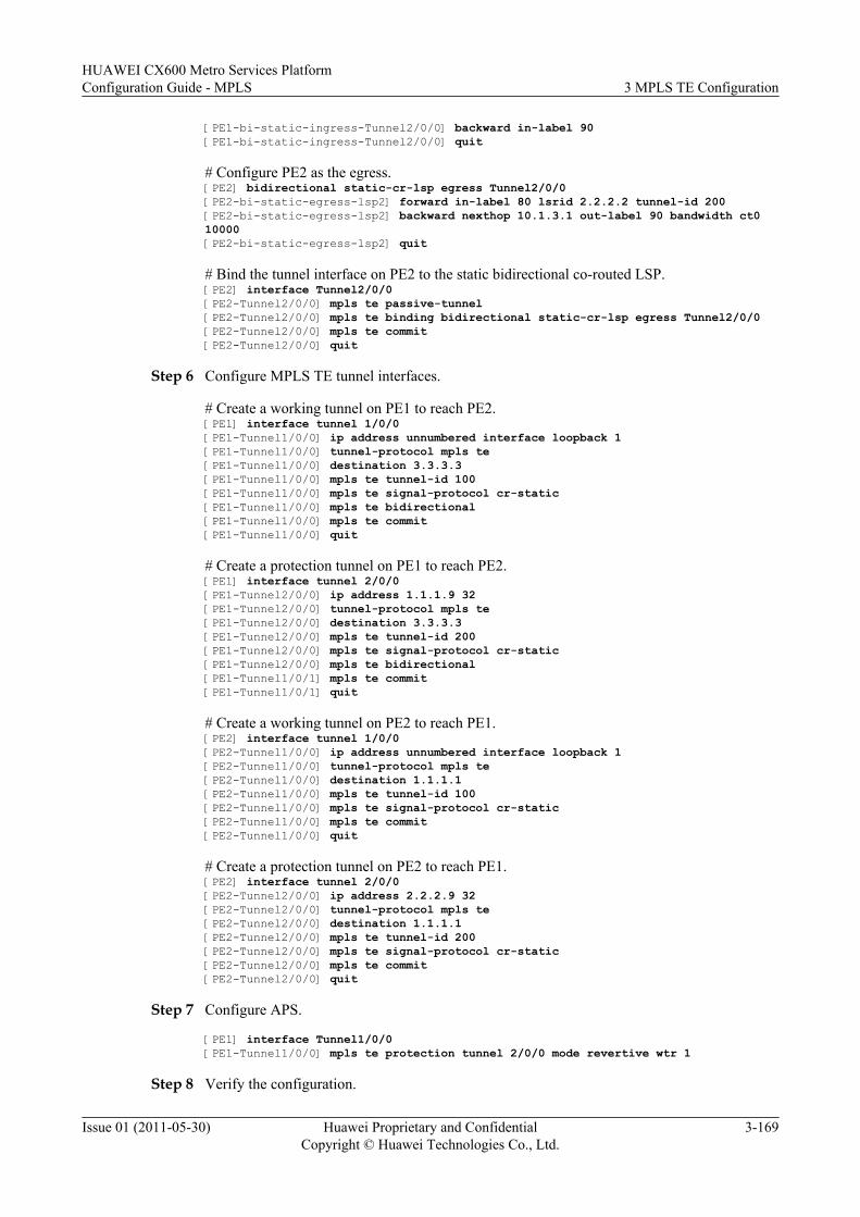
[PE1-bi-static-ingress-Tunnel2/0/0] backward in-label 90[PE1-bi-static-ingress-Tunnel2/0/0] quit
# Configure PE2 as the egress.[PE2] bidirectional static-cr-lsp egress Tunnel2/0/0[PE2-bi-static-egress-lsp2] forward in-label 80 lsrid 2.2.2.2 tunnel-id 200[PE2-bi-static-egress-lsp2] backward nexthop 10.1.3.1 out-label 90 bandwidth ct0 10000[PE2-bi-static-egress-lsp2] quit
# Bind the tunnel interface on PE2 to the static bidirectional co-routed LSP.[PE2] interface Tunnel2/0/0[PE2-Tunnel2/0/0] mpls te passive-tunnel[PE2-Tunnel2/0/0] mpls te binding bidirectional static-cr-lsp egress Tunnel2/0/0[PE2-Tunnel2/0/0] mpls te commit[PE2-Tunnel2/0/0] quit
Step 6 Configure MPLS TE tunnel interfaces.
# Create a working tunnel on PE1 to reach PE2.[PE1] interface tunnel 1/0/0[PE1-Tunnel1/0/0] ip address unnumbered interface loopback 1[PE1-Tunnel1/0/0] tunnel-protocol mpls te[PE1-Tunnel1/0/0] destination 3.3.3.3[PE1-Tunnel1/0/0] mpls te tunnel-id 100[PE1-Tunnel1/0/0] mpls te signal-protocol cr-static[PE1-Tunnel1/0/0] mpls te bidirectional[PE1-Tunnel1/0/0] mpls te commit[PE1-Tunnel1/0/0] quit
# Create a protection tunnel on PE1 to reach PE2.[PE1] interface tunnel 2/0/0[PE1-Tunnel2/0/0] ip address 1.1.1.9 32[PE1-Tunnel2/0/0] tunnel-protocol mpls te[PE1-Tunnel2/0/0] destination 3.3.3.3[PE1-Tunnel2/0/0] mpls te tunnel-id 200[PE1-Tunnel2/0/0] mpls te signal-protocol cr-static[PE1-Tunnel2/0/0] mpls te bidirectional[PE1-Tunnel1/0/1] mpls te commit[PE1-Tunnel1/0/1] quit
# Create a working tunnel on PE2 to reach PE1.[PE2] interface tunnel 1/0/0[PE2-Tunnel1/0/0] ip address unnumbered interface loopback 1[PE2-Tunnel1/0/0] tunnel-protocol mpls te[PE2-Tunnel1/0/0] destination 1.1.1.1[PE2-Tunnel1/0/0] mpls te tunnel-id 100[PE2-Tunnel1/0/0] mpls te signal-protocol cr-static[PE2-Tunnel1/0/0] mpls te commit[PE2-Tunnel1/0/0] quit
# Create a protection tunnel on PE2 to reach PE1.[PE2] interface tunnel 2/0/0[PE2-Tunnel2/0/0] ip address 2.2.2.9 32[PE2-Tunnel2/0/0] tunnel-protocol mpls te[PE2-Tunnel2/0/0] destination 1.1.1.1[PE2-Tunnel2/0/0] mpls te tunnel-id 200[PE2-Tunnel2/0/0] mpls te signal-protocol cr-static[PE2-Tunnel2/0/0] mpls te commit[PE2-Tunnel2/0/0] quit
Step 7 Configure APS.
[PE1] interface Tunnel1/0/0[PE1-Tunnel1/0/0] mpls te protection tunnel 2/0/0 mode revertive wtr 1
Step 8 Verify the configuration.
HUAWEI CX600 Metro Services PlatformConfiguration Guide - MPLS 3 MPLS TE Configuration
Issue 01 (2011-05-30) Huawei Proprietary and ConfidentialCopyright © Huawei Technologies Co., Ltd.
3-169
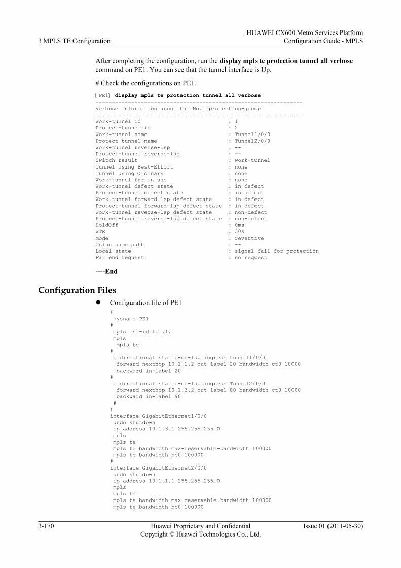
After completing the configuration, run the display mpls te protection tunnel all verbosecommand on PE1. You can see that the tunnel interface is Up.
# Check the configurations on PE1.
[PE1] display mpls te protection tunnel all verbose----------------------------------------------------------------Verbose information about the No.1 protection-group----------------------------------------------------------------Work-tunnel id : 1Protect-tunnel id : 2Work-tunnel name : Tunnel1/0/0Protect-tunnel name : Tunnel2/0/0Work-tunnel reverse-lsp : --Protect-tunnel reverse-lsp : --Switch result : work-tunnelTunnel using Best-Effort : noneTunnel using Ordinary : noneWork-tunnel frr in use : noneWork-tunnel defect state : in defectProtect-tunnel defect state : in defectWork-tunnel forward-lsp defect state : in defectProtect-tunnel forward-lsp defect state : in defectWork-tunnel reverse-lsp defect state : non-defectProtect-tunnel reverse-lsp defect state : non-defectHoldOff : 0msWTR : 30sMode : revertiveUsing same path : --Local state : signal fail for protectionFar end request : no request
----End
Configuration Filesl Configuration file of PE1
# sysname PE1# mpls lsr-id 1.1.1.1 mpls mpls te# bidirectional static-cr-lsp ingress tunnel1/0/0 forward nexthop 10.1.1.2 out-label 20 bandwidth ct0 10000 backward in-label 20# bidirectional static-cr-lsp ingress Tunnel2/0/0 forward nexthop 10.1.3.2 out-label 80 bandwidth ct0 10000 backward in-label 90 ##interface GigabitEthernet1/0/0 undo shutdown ip address 10.1.3.1 255.255.255.0 mpls mpls te mpls te bandwidth max-reservable-bandwidth 100000 mpls te bandwidth bc0 100000#interface GigabitEthernet2/0/0 undo shutdown ip address 10.1.1.1 255.255.255.0 mpls mpls te mpls te bandwidth max-reservable-bandwidth 100000 mpls te bandwidth bc0 100000
3 MPLS TE ConfigurationHUAWEI CX600 Metro Services Platform
Configuration Guide - MPLS
3-170 Huawei Proprietary and ConfidentialCopyright © Huawei Technologies Co., Ltd.
Issue 01 (2011-05-30)
#interface LoopBack1 ip address 1.1.1.1 255.255.255.255#interface Tunnel1/0/0 ip address unnumbered interface LoopBack1 tunnel-protocol mpls te destination 3.3.3.3 mpls te signal-protocol cr-static mpls te tunnel-id 100 mpls te bidirectional mpls te protection tunnel 2/0/0 mode revertive wtr 1 mpls te commit#interface Tunnel2/0/0 ip address 1.1.1.9 255.255.255.255 tunnel-protocol mpls te destination 3.3.3.3 mpls te signal-protocol cr-static mpls te tunnel-id 200 mpls te bidirectional#ospf 1 area 0.0.0.0 network 10.1.1.0 0.0.0.255 network 10.1.2.0 0.0.0.255 network 10.1.3.0 0.0.0.255 network 1.1.1.1 0.0.0.0 network 2.2.2.2 0.0.0.0 network 3.3.3.3 0.0.0.0 network 1.1.1.9 0.0.0.0 # return
l Configuration file of P# sysname P# mpls lsr-id 3.3.3.3 mpls mpls te# bidirectional static-cr-lsp transit lsp1 forward in-label 20 nexthop 10.1.2.1 out-label 40 bandwidth ct0 10000 backward in-label 10 nexthop 10.1.1.1 out-label 20 bandwidth ct0 10000#interface GigabitEthernet1/0/0 undo shutdown ip address 10.1.1.2 255.255.255.0 mpls mpls te mpls te bandwidth max-reservable-bandwidth 100000 mpls te bandwidth bc0 100000#interface GigabitEthernet2/0/0 undo shutdown ip address 10.1.2.2 255.255.255.0 mpls mpls te mpls te bandwidth max-reservable-bandwidth 100000 mpls te bandwidth bc0 100000#interface LoopBack1 ip address 3.3.3.3 255.255.255.255#ospf 1 area 0.0.0.0 network 10.1.1.0 0.0.0.255 network 10.1.2.0 0.0.0.255 network 10.1.3.0 0.0.0.255
HUAWEI CX600 Metro Services PlatformConfiguration Guide - MPLS 3 MPLS TE Configuration
Issue 01 (2011-05-30) Huawei Proprietary and ConfidentialCopyright © Huawei Technologies Co., Ltd.
3-171
network 1.1.1.1 0.0.0.0 network 2.2.2.2 0.0.0.0 network 3.3.3.3 0.0.0.0 network 1.1.1.9 0.0.0.0 # return
l Configuration file of PE2# sysname PE2# mpls lsr-id 2.2.2.2 mpls mpls te# bidirectional static-cr-lsp ingress tunnel1/0/0 forward in-label 40 lsrid 2.2.2.2 tunnel-id 100 backward nexthop 10.1.2.2 out-label 10 bandwidth ct0 10000# bidirectional static-cr-lsp ingress Tunnel2/0/0 forward in-label 80 lsrid 2.2.2.2 tunnel-id 200 backward nexthop 10.1.3.1 out-label 90 bandwidth ct0 10000 ##interface GigabitEthernet1/0/0 undo shutdown ip address 10.1.3.2 255.255.255.0 mpls mpls te mpls te bandwidth max-reservable-bandwidth 100000 mpls te bandwidth bc0 100000#interface GigabitEthernet2/0/0 undo shutdown ip address 10.1.2.1 255.255.255.0 mpls mpls te mpls te bandwidth max-reservable-bandwidth 100000 mpls te bandwidth bc0 100000#interface LoopBack1 ip address 2.2.2.2 255.255.255.255#interface Tunnel1/0/0 ip address unnumbered interface LoopBack1 tunnel-protocol mpls te destination 1.1.1.1 mpls te signal-protocol cr-static mpls te tunnel-id 100 mpls te bidirectional mpls te passive-tunnel mpls te binding bidirectional static-cr-lsp egress Tunnel1/0/0 mpls te commit#interface Tunnel2/0/0 ip address 1.1.1.9 255.255.255.255 tunnel-protocol mpls te destination 1.1.1.1 mpls te signal-protocol cr-static mpls te tunnel-id 200 mpls te bidirectional mpls te passive-tunnel mpls te binding bidirectional static-cr-lsp egress Tunnel2/0/0 mpls te commit#ospf 1 area 0.0.0.0 network 10.1.1.0 0.0.0.255 network 10.1.2.0 0.0.0.255 network 10.1.3.0 0.0.0.255
3 MPLS TE ConfigurationHUAWEI CX600 Metro Services Platform
Configuration Guide - MPLS
3-172 Huawei Proprietary and ConfidentialCopyright © Huawei Technologies Co., Ltd.
Issue 01 (2011-05-30)
network 1.1.1.1 0.0.0.0 network 2.2.2.2 0.0.0.0 network 3.3.3.3 0.0.0.0 network 1.1.1.9 0.0.0.0 # return
3.26.4 Example for Configuring RSVP-TE TunnelThis section provides an example for configuring an RSVP-TE tunnel, including enablingMPLS, MPLS TE, RSVP-TE, and CSPF.
Networking Requirements
On the network shown in Figure 3-5, IS-IS is run on LSR A, LSR B, LSR C, and LSR D. Theyare all Level 2 devices.
RSVP-TE is used to establish a TE tunnel from LSR A to LSR D. The bandwidth is 20 Mbit/s. The maximum reservable bandwidth of links along the tunnel is 100 Mbit/s. The bandwidthconstraints model is the default RDM and the bandwidth of BC0 is 100 Mbit/s.
Figure 3-5 Networking diagram of the RSVP-TE tunnel
Loopback14.4.4.9/32
Loopback13.3.3.9/32
Loopback12.2.2.9/32
LSRD
LSRC
POS2/0/020.1.1.1/24
POS2/0/020.1.1.2/24
GE1/0/030.1.1.1/24
GE1/0/030.1.1.2/24
LSRA
LSRB
GE1/0/010.1.1.1/24
GE1/0/010.1.1.2/24
Loopback11.1.1.9/32
Configuration Roadmap
The configuration roadmap is as follows:
1. Configure IP addresses for the interfaces on each LSR and configuring loopback addressas the LSR ID.
2. Enable IS-IS globally, configure the name of network entity, change cost type, enable IS-IS TE and enable IS-IS on all interfaces including loopback interfaces.
3. Configure LSR ID and enable MPLS, MPLS TE, MPLS RSVP-TE, and MPLS TE CSPFglobally.
4. Enable MPLS, MPLS TE, and MPLS RSVP-TE on each interface.5. Configure the maximum reservable bandwidth and BC bandwidth for the links on each
LSR along the tunnel.
HUAWEI CX600 Metro Services PlatformConfiguration Guide - MPLS 3 MPLS TE Configuration
Issue 01 (2011-05-30) Huawei Proprietary and ConfidentialCopyright © Huawei Technologies Co., Ltd.
3-173
6. Create the tunnel interface on the ingress and specifying the IP address, tunnel protocol,destination address, tunnel ID, dynamic signaling protocol RSVP-TE, and tunnelbandwidth.
Data PreparationTo complete the configuration, you need the following data:
l IS-IS area ID of each LSR, originating system ID, and IS-IS levell Maximum reservable bandwidth and BC bandwidth for the links along the tunnell Tunnel interface name, IP address, destination address, tunnel ID, tunnel signaling protocol
(RSVP-TE), and tunnel bandwidth
Configuration Procedure1. Configure IP addresses for interfaces.
Configure the IP address and mask on each interface as shown in Figure 3-5. The detailedconfiguration is not mentioned here.
2. Configure the IS-IS protocol to advertise routes.# Configure LSR A.[LSRA] isis 1[LSRA-isis-1] network-entity 00.0005.0000.0000.0001.00[LSRA-isis-1] is-level level-2[LSRA-isis-1] quit[LSRA] interface gigabitethernet 1/0/0[LSRA-GigabitEthernet1/0/0] isis enable 1[LSRA-GigabitEthernet1/0/0] quit[LSRA] interface loopback 1[LSRA-LoopBack1] isis enable 1[LSRA-LoopBack1] quit# Configure LSR B.[LSRB] isis 1[LSRB-isis-1] network-entity 00.0005.0000.0000.0002.00[LSRB-isis-1] is-level level-2[LSRB-isis-1] quit[LSRB] interface gigabitethernet 1/0/0[LSRB-GigabitEthernet1/0/0] isis enable 1[LSRB-GigabitEthernet1/0/0] quit[LSRB] interface pos 2/0/0[LSRB-Pos2/0/0] isis enable 1[LSRB-Pos2/0/0] quit[LSRB] interface loopback 1[LSRB-LoopBack1] isis enable 1[LSRB-LoopBack1] quit# Configure LSR C.[LSRC] isis 1[LSRC-isis-1] network-entity 00.0005.0000.0000.0003.00[LSRC-isis-1] is-level level-2[LSRC-isis-1] quit[LSRC] interface gigabitethernet 1/0/0[LSRC-GigabitEthernet1/0/0] isis enable 1[LSRC-GigabitEthernet1/0/0] quit[LSRC] interface pos 2/0/0[LSRC-Pos2/0/0] isis enable 1[LSRC-Pos2/0/0] quit[LSRC] interface loopback 1[LSRC-LoopBack1] isis enable 1[LSRC-LoopBack1] quit# Configure LSR D.
3 MPLS TE ConfigurationHUAWEI CX600 Metro Services Platform
Configuration Guide - MPLS
3-174 Huawei Proprietary and ConfidentialCopyright © Huawei Technologies Co., Ltd.
Issue 01 (2011-05-30)
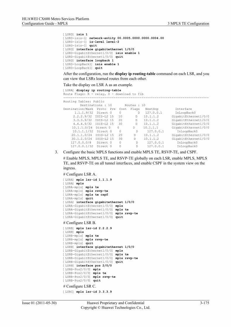
[LSRD] isis 1[LSRD-isis-1] network-entity 00.0005.0000.0000.0004.00[LSRD-isis-1] is-level level-2[LSRD-isis-1] quit[LSRD] interface gigabitethernet 1/0/0[LSRD-GigabitEthernet1/0/0] isis enable 1[LSRD-GigabitEthernet1/0/0] quit[LSRD] interface loopback 1[LSRD-LoopBack1] isis enable 1[LSRD-LoopBack1] quitAfter the configuration, run the display ip routing-table command on each LSR, and youcan view that LSRs learned routes from each other.Take the display on LSR A as an example.[LSRA] display ip routing-tableRoute Flags: R - relay, D - download to fib------------------------------------------------------------------------------Routing Tables: Public Destinations : 10 Routes : 10Destination/Mask Proto Pre Cost Flags NextHop Interface 1.1.1.9/32 Direct 0 0 D 127.0.0.1 InLoopBack0 2.2.2.9/32 ISIS-L2 15 10 D 10.1.1.2 GigabitEthernet1/0/0 3.3.3.9/32 ISIS-L2 15 20 D 10.1.1.2 GigabitEthernet1/0/0 4.4.4.9/32 ISIS-L2 15 30 D 10.1.1.2 GigabitEthernet1/0/0 10.1.1.0/24 Direct 0 0 D 10.1.1.1 GigabitEthernet1/0/0 10.1.1.1/32 Direct 0 0 D 127.0.0.1 InLoopBack0 20.1.1.0/24 ISIS-L2 15 20 D 10.1.1.2 GigabitEthernet1/0/0 30.1.1.0/24 ISIS-L2 15 30 D 10.1.1.2 GigabitEthernet1/0/0 127.0.0.0/8 Direct 0 0 D 127.0.0.1 InLoopBack0 127.0.0.1/32 Direct 0 0 D 127.0.0.1 InLoopBack0
3. Configure the basic MPLS functions and enable MPLS TE, RSVP-TE, and CSPF.# Enable MPLS, MPLS TE, and RSVP-TE globally on each LSR, enable MPLS, MPLSTE, and RSVP-TE on all tunnel interfaces, and enable CSPF in the system view on theingress.# Configure LSR A.[LSRA] mpls lsr-id 1.1.1.9[LSRA] mpls[LSRA-mpls] mpls te[LSRA-mpls] mpls rsvp-te[LSRA-mpls] mpls te cspf[LSRA-mpls] quit[LSRA] interface gigabitethernet 1/0/0[LSRA-GigabitEthernet1/0/0] mpls[LSRA-GigabitEthernet1/0/0] mpls te[LSRA-GigabitEthernet1/0/0] mpls rsvp-te[LSRA-GigabitEthernet1/0/0] quit# Configure LSR B.[LSRB] mpls lsr-id 2.2.2.9[LSRB] mpls[LSRB-mpls] mpls te[LSRB-mpls] mpls rsvp-te[LSRB-mpls] quit[LSRB] interface gigabitethernet 1/0/0[LSRB-GigabitEthernet1/0/0] mpls[LSRB-GigabitEthernet1/0/0] mpls te[LSRB-GigabitEthernet1/0/0] mpls rsvp-te[LSRB-GigabitEthernet1/0/0] quit[LSRB] interface pos 2/0/0[LSRB-Pos2/0/0] mpls[LSRB-Pos2/0/0] mpls te[LSRB-Pos2/0/0] mpls rsvp-te[LSRB-Pos2/0/0] quit# Configure LSR C.[LSRC] mpls lsr-id 3.3.3.9
HUAWEI CX600 Metro Services PlatformConfiguration Guide - MPLS 3 MPLS TE Configuration
Issue 01 (2011-05-30) Huawei Proprietary and ConfidentialCopyright © Huawei Technologies Co., Ltd.
3-175
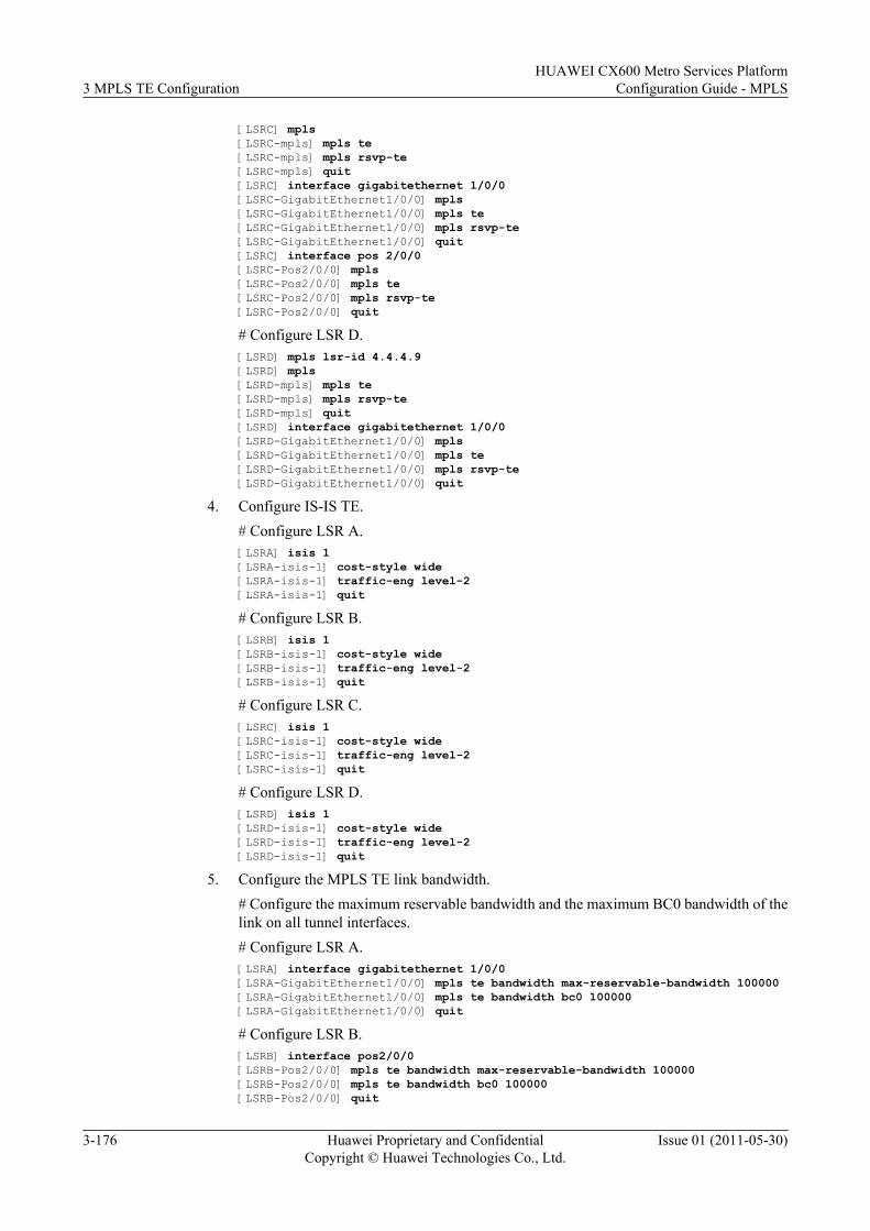
[LSRC] mpls[LSRC-mpls] mpls te[LSRC-mpls] mpls rsvp-te[LSRC-mpls] quit[LSRC] interface gigabitethernet 1/0/0[LSRC-GigabitEthernet1/0/0] mpls[LSRC-GigabitEthernet1/0/0] mpls te[LSRC-GigabitEthernet1/0/0] mpls rsvp-te[LSRC-GigabitEthernet1/0/0] quit[LSRC] interface pos 2/0/0[LSRC-Pos2/0/0] mpls[LSRC-Pos2/0/0] mpls te[LSRC-Pos2/0/0] mpls rsvp-te[LSRC-Pos2/0/0] quit
# Configure LSR D.[LSRD] mpls lsr-id 4.4.4.9[LSRD] mpls[LSRD-mpls] mpls te[LSRD-mpls] mpls rsvp-te[LSRD-mpls] quit[LSRD] interface gigabitethernet 1/0/0[LSRD-GigabitEthernet1/0/0] mpls[LSRD-GigabitEthernet1/0/0] mpls te[LSRD-GigabitEthernet1/0/0] mpls rsvp-te[LSRD-GigabitEthernet1/0/0] quit
4. Configure IS-IS TE.# Configure LSR A.[LSRA] isis 1[LSRA-isis-1] cost-style wide[LSRA-isis-1] traffic-eng level-2[LSRA-isis-1] quit
# Configure LSR B.[LSRB] isis 1[LSRB-isis-1] cost-style wide[LSRB-isis-1] traffic-eng level-2[LSRB-isis-1] quit
# Configure LSR C.[LSRC] isis 1[LSRC-isis-1] cost-style wide[LSRC-isis-1] traffic-eng level-2[LSRC-isis-1] quit
# Configure LSR D.[LSRD] isis 1[LSRD-isis-1] cost-style wide[LSRD-isis-1] traffic-eng level-2[LSRD-isis-1] quit
5. Configure the MPLS TE link bandwidth.# Configure the maximum reservable bandwidth and the maximum BC0 bandwidth of thelink on all tunnel interfaces.# Configure LSR A.[LSRA] interface gigabitethernet 1/0/0[LSRA-GigabitEthernet1/0/0] mpls te bandwidth max-reservable-bandwidth 100000[LSRA-GigabitEthernet1/0/0] mpls te bandwidth bc0 100000[LSRA-GigabitEthernet1/0/0] quit
# Configure LSR B.[LSRB] interface pos2/0/0[LSRB-Pos2/0/0] mpls te bandwidth max-reservable-bandwidth 100000[LSRB-Pos2/0/0] mpls te bandwidth bc0 100000[LSRB-Pos2/0/0] quit
3 MPLS TE ConfigurationHUAWEI CX600 Metro Services Platform
Configuration Guide - MPLS
3-176 Huawei Proprietary and ConfidentialCopyright © Huawei Technologies Co., Ltd.
Issue 01 (2011-05-30)
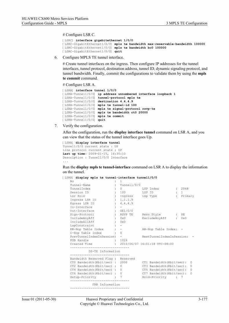
# Configure LSR C.[LSRC] interface gigabitethernet 1/0/0[LSRC-GigabitEthernet1/0/0] mpls te bandwidth max-reservable-bandwidth 100000[LSRC-GigabitEthernet1/0/0] mpls te bandwidth bc0 100000[LSRC-GigabitEthernet1/0/0] quit
6. Configure MPLS TE tunnel interface.# Create tunnel interfaces on the ingress. Then configure IP addresses for the tunnelinterfaces, tunnel protocol, destination address, tunnel ID, dynamic signaling protocol, andtunnel bandwidth. Finally, commit the configurations to validate them by using the mplste commit command.# Configure LSR A.[LSRA] interface tunnel 1/0/0[LSRA-Tunnel1/0/0] ip address unnumbered interface loopback 1[LSRA-Tunnel1/0/0] tunnel-protocol mpls te[LSRA-Tunnel1/0/0] destination 4.4.4.9[LSRA-Tunnel1/0/0] mpls te tunnel-id 100[LSRA-Tunnel1/0/0] mpls te signal-protocol rsvp-te[LSRA-Tunnel1/0/0] mpls te bandwidth ct0 20000[LSRA-Tunnel1/0/0] mpls te commit[LSRA-Tunnel1/0/0] quit
7. Verify the configuration.After the configuration, run the display interface tunnel command on LSR A, and youcan view that the status of the tunnel interface goes Up.[LSRA] display interface tunnelTunnel1/0/0 current state : UPLine protocol current state : UPLast up time: 2009-01-15, 16:35:10Description : Tunnel1/0/0 Interface...Run the display mpls te tunnel-interface command on LSR A to display the informationon the tunnel.[LSRA] display mpls te tunnel-interface tunnel1/0/0 No : 1 Tunnel-Name : Tunnel1/0/0 TunnelIndex : 0 LSP Index : 2048 Session ID : 100 LSP ID : 1 Lsr Role : Ingress Lsp Type : Primary Ingress LSR ID : 1.1.1.9 Egress LSR ID : 4.4.4.9 In-Interface : - Out-Interface : GE1/0/0 Sign-Protocol : RSVP TE Resv Style : SE IncludeAnyAff : 0x0 ExcludeAnyAff : 0x0 IncludeAllAff : 0x0 LspConstraint : - ER-Hop Table Index : - AR-Hop Table Index: - C-Hop Table Index : 0 PrevTunnelIndexInSession: - NextTunnelIndexInSession: - PSB Handle : 1024 Created Time : 2010/06/07 16:01:18 UTC-08:00 -------------------------------- DS-TE Information -------------------------------- Bandwidth Reserved Flag : Reserved CT0 Bandwidth(Kbit/sec) : 2000 CT1 Bandwidth(Kbit/sec): 0 CT2 Bandwidth(Kbit/sec) : 0 CT3 Bandwidth(Kbit/sec): 0 CT4 Bandwidth(Kbit/sec) : 0 CT5 Bandwidth(Kbit/sec): 0 CT6 Bandwidth(Kbit/sec) : 0 CT7 Bandwidth(Kbit/sec): 0 Setup-Priority : 7 Hold-Priority : 7 -------------------------------- FRR Information --------------------------------
HUAWEI CX600 Metro Services PlatformConfiguration Guide - MPLS 3 MPLS TE Configuration
Issue 01 (2011-05-30) Huawei Proprietary and ConfidentialCopyright © Huawei Technologies Co., Ltd.
3-177
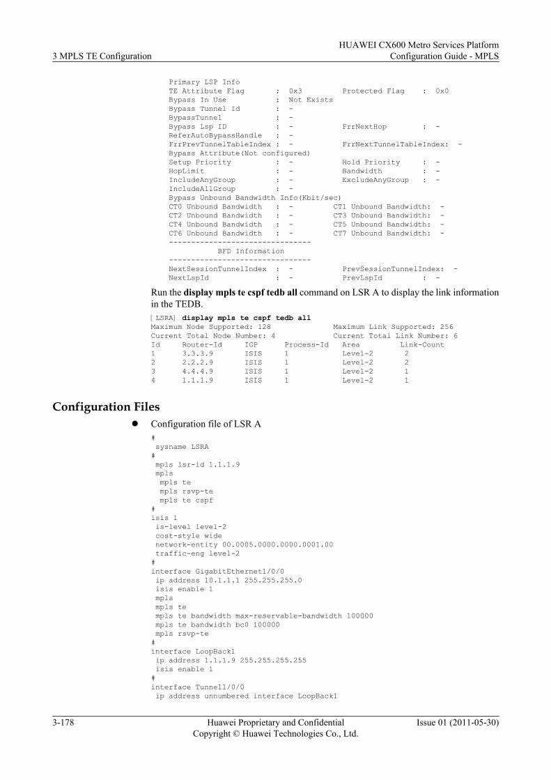
Primary LSP Info TE Attribute Flag : 0x3 Protected Flag : 0x0 Bypass In Use : Not Exists Bypass Tunnel Id : - BypassTunnel : - Bypass Lsp ID : - FrrNextHop : - ReferAutoBypassHandle : - FrrPrevTunnelTableIndex : - FrrNextTunnelTableIndex: - Bypass Attribute(Not configured) Setup Priority : - Hold Priority : - HopLimit : - Bandwidth : - IncludeAnyGroup : - ExcludeAnyGroup : - IncludeAllGroup : - Bypass Unbound Bandwidth Info(Kbit/sec) CT0 Unbound Bandwidth : - CT1 Unbound Bandwidth: - CT2 Unbound Bandwidth : - CT3 Unbound Bandwidth: - CT4 Unbound Bandwidth : - CT5 Unbound Bandwidth: - CT6 Unbound Bandwidth : - CT7 Unbound Bandwidth: - -------------------------------- BFD Information -------------------------------- NextSessionTunnelIndex : - PrevSessionTunnelIndex: - NextLspId : - PrevLspId : -
Run the display mpls te cspf tedb all command on LSR A to display the link informationin the TEDB.[LSRA] display mpls te cspf tedb allMaximum Node Supported: 128 Maximum Link Supported: 256Current Total Node Number: 4 Current Total Link Number: 6Id Router-Id IGP Process-Id Area Link-Count1 3.3.3.9 ISIS 1 Level-2 22 2.2.2.9 ISIS 1 Level-2 23 4.4.4.9 ISIS 1 Level-2 14 1.1.1.9 ISIS 1 Level-2 1
Configuration Filesl Configuration file of LSR A
# sysname LSRA# mpls lsr-id 1.1.1.9 mpls mpls te mpls rsvp-te mpls te cspf#isis 1 is-level level-2 cost-style wide network-entity 00.0005.0000.0000.0001.00 traffic-eng level-2#interface GigabitEthernet1/0/0 ip address 10.1.1.1 255.255.255.0 isis enable 1 mpls mpls te mpls te bandwidth max-reservable-bandwidth 100000 mpls te bandwidth bc0 100000 mpls rsvp-te#interface LoopBack1 ip address 1.1.1.9 255.255.255.255 isis enable 1#interface Tunnel1/0/0 ip address unnumbered interface LoopBack1
3 MPLS TE ConfigurationHUAWEI CX600 Metro Services Platform
Configuration Guide - MPLS
3-178 Huawei Proprietary and ConfidentialCopyright © Huawei Technologies Co., Ltd.
Issue 01 (2011-05-30)
tunnel-protocol mpls te destination 4.4.4.9 mpls te tunnel-id 100 mpls te bandwidth ct0 20000 mpls te commit#return
l Configuration file of LSR B# sysname LSRB# mpls lsr-id 2.2.2.9 mpls mpls te mpls rsvp-te#isis 1 is-level level-2 cost-style wide network-entity 00.0005.0000.0000.0002.00 traffic-eng level-2#interface GigabitEthernet1/0/0 ip address 10.1.1.2 255.255.255.0 isis enable 1 mpls mpls te mpls rsvp-te#interface Pos2/0/0 link-protocol ppp clock master ip address 20.1.1.1 255.255.255.0 isis enable 1 mpls mpls te mpls te bandwidth max-reservable-bandwidth 100000 mpls te bandwidth bc0 100000 mpls rsvp-te#interface LoopBack1 ip address 2.2.2.9 255.255.255.255 isis enable 1#return
l Configuration file of LSR C# sysname LSRC# mpls lsr-id 3.3.3.9 mpls mpls te mpls rsvp-te#isis 1 is-level level-2 cost-style wide network-entity 00.0005.0000.0000.0003.00 traffic-eng level-2#interface GigabitEthernet1/0/0 ip address 30.1.1.1 255.255.255.0 isis enable 1 mpls mpls te mpls te bandwidth max-reservable-bandwidth 100000 mpls te bandwidth bc0 100000 mpls rsvp-te
HUAWEI CX600 Metro Services PlatformConfiguration Guide - MPLS 3 MPLS TE Configuration
Issue 01 (2011-05-30) Huawei Proprietary and ConfidentialCopyright © Huawei Technologies Co., Ltd.
3-179
#interface Pos2/0/0 link-protocol ppp ip address 20.1.1.2 255.255.255.0 isis enable 1 mpls mpls te mpls rsvp-te#interface LoopBack1 ip address 3.3.3.9 255.255.255.255 isis enable 1#return
l Configuration file of LSR D# sysname LSRD# mpls lsr-id 4.4.4.9 mpls mpls te mpls rsvp-te#isis 1 is-level level-2 cost-style wide network-entity 00.0005.0000.0000.0004.00 traffic-eng level-2#interface GigabitEthernet1/0/0 ip address 30.1.1.2 255.255.255.0 isis enable 1 mpls mpls te mpls rsvp-te#interface LoopBack1 ip address 4.4.4.9 255.255.255.255 isis enable 1#return
3.26.5 Example for Setting Up a CR-LSP by Using the CR-LSPAttribute Template
This section provides an example for setting up a CR-LSP by using a CR-LSP attribute template,including the configurations of enabling MPLS and MPLS TE, configuring a CR-LSP attributetemplate, and using the CR-LSP attribute template to set up a CR-LSP.
Networking RequirementsOn the network shown in Figure 3-6, a primary CR-LSP is set up, with LSR A being the ingressand LSR D being the egress. The primary CR-LSP needs to be configured with a hot-standbyCR-LSP and an ordinary backup CR-LSP. In this manner, when the primary CR-LSP fails, trafficcan be switched to the hot-standby CR-LSP or ordinary backup CR-LSP.
3 MPLS TE ConfigurationHUAWEI CX600 Metro Services Platform
Configuration Guide - MPLS
3-180 Huawei Proprietary and ConfidentialCopyright © Huawei Technologies Co., Ltd.
Issue 01 (2011-05-30)
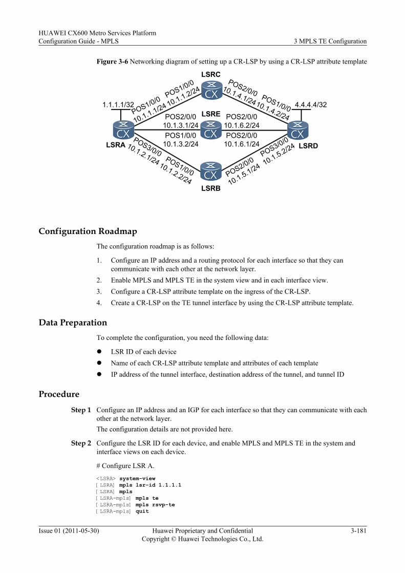
Figure 3-6 Networking diagram of setting up a CR-LSP by using a CR-LSP attribute template
POS2/0/010.1.6.2/24
1.1.1.1/32 4.4.4.4/32
POS2/0/0
10.1.5.1/24
POS1/0/0
10.1.1.1/24POS2/0/0
10.1.3.1/24
POS3/0/010.1.2.1/24 POS1/0/0
10.1.2.2/24
POS3/0/0
10.1.5.2/24POS1/0/0
10.1.3.2/24POS2/0/0
10.1.6.1/24
POS1/0/0
10.1.1.2/24POS2/0/010.1.4.1/24 POS1/0/010.1.4.2/24
LSRA
LSRC
LSRD
LSRB
LSRE
Configuration RoadmapThe configuration roadmap is as follows:
1. Configure an IP address and a routing protocol for each interface so that they cancommunicate with each other at the network layer.
2. Enable MPLS and MPLS TE in the system view and in each interface view.3. Configure a CR-LSP attribute template on the ingress of the CR-LSP.4. Create a CR-LSP on the TE tunnel interface by using the CR-LSP attribute template.
Data PreparationTo complete the configuration, you need the following data:
l LSR ID of each devicel Name of each CR-LSP attribute template and attributes of each templatel IP address of the tunnel interface, destination address of the tunnel, and tunnel ID
Procedure
Step 1 Configure an IP address and an IGP for each interface so that they can communicate with eachother at the network layer.The configuration details are not provided here.
Step 2 Configure the LSR ID for each device, and enable MPLS and MPLS TE in the system andinterface views on each device.
# Configure LSR A.
<LSRA> system-view[LSRA] mpls lsr-id 1.1.1.1[LSRA] mpls [LSRA-mpls] mpls te[LSRA-mpls] mpls rsvp-te[LSRA-mpls] quit
HUAWEI CX600 Metro Services PlatformConfiguration Guide - MPLS 3 MPLS TE Configuration
Issue 01 (2011-05-30) Huawei Proprietary and ConfidentialCopyright © Huawei Technologies Co., Ltd.
3-181
[LSRA] interface pos1/0/0[LSRA-Pos1/0/0] mpls[LSRA-Pos1/0/0] mpls te[LSRA-Pos1/0/0] mpls rsvp-te[LSRA-Pos1/0/0] quit[LSRA] interface pos2/0/0[LSRA-Pos2/0/0] mpls[LSRA-Pos2/0/0] mpls te[LSRA-Pos2/0/0] mpls rsvp-te[LSRA-Pos2/0/0] quit[LSRA] interface pos3/0/0[LSRA-Pos3/0/0] mpls[LSRA-Pos3/0/0] mpls te[LSRA-Pos3/0/0] mpls rsvp-te[LSRA-Pos3/0/0] quit
NOTE
The configurations of LSR B, LSR C, LSR D, and LSR E are similar to those of LSR A, and are not providedhere.
Step 3 Configure a CR-LSP attribute template and its explicit paths.
# On LSR A, configure the path LSR A->LSR C->LSR D as the explicit path namedup_path.
[LSRA] explicit-path up_path[LSRA-explicit-path-up_path] next hop 10.1.1.2[LSRA-explicit-path-up_path] next hop 10.1.4.2[LSRA-explicit-path-up_path] quit
# On LSR A, configure the path LSRA->LSRB->LSRD as the explicit path nameddown_path.
[LSRA] explicit-path down_path[LSRA-explicit-path-down_path] next hop 10.1.2.2[LSRA-explicit-path-down_path] next hop 10.1.5.2[LSRA-explicit-path-down_path] quit
# On LSR A, configure the path LSRA->LSRE->LSRD as the explicit path namedmiddle_path.
[LSRA] explicit-path middle_path[LSRA-explicit-path-middle_path] next hop 10.1.3.2[LSRA-explicit-path-middle_path] next hop 10.1.6.2[LSRA-explicit-path-middle_path] quit
# On LSR A, configure the CR-LSP attribute template named lsp_attribute_1.
[LSRA] lsp-attribute lsp_attribute_1[LSRA-lsp-attribuLSP_attribute_1] explicit-path up_path[LSRA-lsp-attribuLSP_attribute_1] priority 5 5[LSRA-lsp-attribuLSP_attribute_1] hop-limit 12[LSRA-lsp-attribuLSP_attribute_1] commit
# On LSR A, configure the CR-LSP attribute template named lsp_attribute_2.
[LSRA] lsp-attribute lsp_attribute_2[LSRA-lsp-attribuLSP_attribute_2] explicit-path down_path[LSRA-lsp-attribuLSP_attribute_2] priority 5 5[LSRA-lsp-attribuLSP_attribute_2] hop-limit 15[LSRA-lsp-attribuLSP_attribute_2] commit
# On LSR A, configure the CR-LSP attribute template named lsp_attribute_3.
[LSRA] lsp-attribute lsp_attribute_3[LSRA-lsp-attribuLSP_attribute_3] explicit-path middle_path[LSRA-lsp-attribuLSP_attribute_3] priority 5 5[LSRA-lsp-attribuLSP_attribute_3] commit
3 MPLS TE ConfigurationHUAWEI CX600 Metro Services Platform
Configuration Guide - MPLS
3-182 Huawei Proprietary and ConfidentialCopyright © Huawei Technologies Co., Ltd.
Issue 01 (2011-05-30)
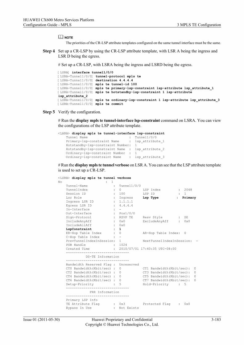
NOTEThe priorities of the CR-LSP attribute templates configured on the same tunnel interface must be the same.
Step 4 Set up a CR-LSP by using the CR-LSP attribute template, with LSR A being the ingress andLSR D being the egress.
# Set up a CR-LSP, with LSRA being the ingress and LSRD being the egress.
[LSRA] interface tunnel1/0/0[LSRA-Tunnel1/0/0] tunnel-protocol mpls te[LSRA-Tunnel1/0/0] destination 4.4.4.4[LSRA-Tunnel1/0/0] mpls te tunnel-id 100[LSRA-Tunnel1/0/0] mpls te primary-lsp-constraint lsp-attribute lsp_attribute_1[LSRA-Tunnel1/0/0] mpls te hotstandby-lsp-constraint 1 lsp-attribute lsp_attribute_2[LSRA-Tunnel1/0/0] mpls te ordinary-lsp-constraint 1 lsp-attribute lsp_attribute_3[LSRA-Tunnel1/0/0] mpls te commit
Step 5 Verify the configuration.
# Run the display mpls te tunnel-interface lsp-constraint command on LSRA. You can viewthe configurations of the LSP attribute template.
<LARA> display mpls te tunnel-interface lsp-constraint Tunnel Name : Tunnel1/0/0 Primary-lsp-constraint Name : lsp_attribute_1 Hotstandby-lsp-constraint Number: 1 Hotstandby-lsp-constraint Name : lsp_attribute_2 Ordinary-lsp-constraint Number : 1 Ordinary-lsp-constraint Name : lsp_attribute_3
# Run the display mpls te tunnel verbose on LSR A. You can see that the LSP attribute templateis used to set up a CR-LSP.
<LSRA> display mpls te tunnel verboseNo : 1 Tunnel-Name : Tunnel1/0/0 TunnelIndex : 0 LSP Index : 2048 Session ID : 100 LSP ID : 1 Lsr Role : Ingress Lsp Type : Primary Ingress LSR ID : 1.1.1.1 Egress LSR ID : 4.4.4.4 In-Interface : - Out-Interface : Pos1/0/0 Sign-Protocol : RSVP TE Resv Style : SE IncludeAnyAff : 0x0 ExcludeAnyAff : 0x0 IncludeAllAff : 0x0 LspConstraint : 1 ER-Hop Table Index : 0 AR-Hop Table Index: 0 C-Hop Table Index : - PrevTunnelIndexInSession: 1 NextTunnelIndexInSession: - PSB Handle : 1024 Created Time : 2010/07/01 17:40:35 UTC-08:00 -------------------------------- DS-TE Information -------------------------------- Bandwidth Reserved Flag : Unreserved CT0 Bandwidth(Kbit/sec) : 0 CT1 Bandwidth(Kbit/sec): 0 CT2 Bandwidth(Kbit/sec) : 0 CT3 Bandwidth(Kbit/sec): 0 CT4 Bandwidth(Kbit/sec) : 0 CT5 Bandwidth(Kbit/sec): 0 CT6 Bandwidth(Kbit/sec) : 0 CT7 Bandwidth(Kbit/sec): 0 Setup-Priority : 5 Hold-Priority : 5 -------------------------------- FRR Information -------------------------------- Primary LSP Info TE Attribute Flag : 0x3 Protected Flag : 0x0 Bypass In Use : Not Exists
HUAWEI CX600 Metro Services PlatformConfiguration Guide - MPLS 3 MPLS TE Configuration
Issue 01 (2011-05-30) Huawei Proprietary and ConfidentialCopyright © Huawei Technologies Co., Ltd.
3-183
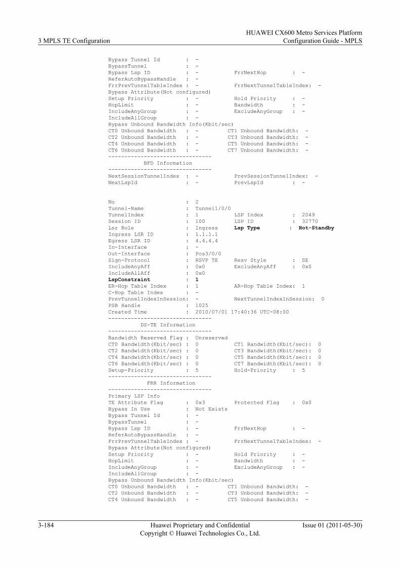
Bypass Tunnel Id : - BypassTunnel : - Bypass Lsp ID : - FrrNextHop : - ReferAutoBypassHandle : - FrrPrevTunnelTableIndex : - FrrNextTunnelTableIndex: - Bypass Attribute(Not configured) Setup Priority : - Hold Priority : - HopLimit : - Bandwidth : - IncludeAnyGroup : - ExcludeAnyGroup : - IncludeAllGroup : - Bypass Unbound Bandwidth Info(Kbit/sec) CT0 Unbound Bandwidth : - CT1 Unbound Bandwidth: - CT2 Unbound Bandwidth : - CT3 Unbound Bandwidth: - CT4 Unbound Bandwidth : - CT5 Unbound Bandwidth: - CT6 Unbound Bandwidth : - CT7 Unbound Bandwidth: - -------------------------------- BFD Information -------------------------------- NextSessionTunnelIndex : - PrevSessionTunnelIndex: - NextLspId : - PrevLspId : -
No : 2 Tunnel-Name : Tunnel1/0/0 TunnelIndex : 1 LSP Index : 2049 Session ID : 100 LSP ID : 32770 Lsr Role : Ingress Lsp Type : Hot-Standby Ingress LSR ID : 1.1.1.1 Egress LSR ID : 4.4.4.4 In-Interface : - Out-Interface : Pos3/0/0 Sign-Protocol : RSVP TE Resv Style : SE IncludeAnyAff : 0x0 ExcludeAnyAff : 0x0 IncludeAllAff : 0x0 LspConstraint : 1 ER-Hop Table Index : 1 AR-Hop Table Index: 1 C-Hop Table Index : - PrevTunnelIndexInSession: - NextTunnelIndexInSession: 0 PSB Handle : 1025 Created Time : 2010/07/01 17:40:36 UTC-08:00 -------------------------------- DS-TE Information -------------------------------- Bandwidth Reserved Flag : Unreserved CT0 Bandwidth(Kbit/sec) : 0 CT1 Bandwidth(Kbit/sec): 0 CT2 Bandwidth(Kbit/sec) : 0 CT3 Bandwidth(Kbit/sec): 0 CT4 Bandwidth(Kbit/sec) : 0 CT5 Bandwidth(Kbit/sec): 0 CT6 Bandwidth(Kbit/sec) : 0 CT7 Bandwidth(Kbit/sec): 0 Setup-Priority : 5 Hold-Priority : 5 -------------------------------- FRR Information -------------------------------- Primary LSP Info TE Attribute Flag : 0x3 Protected Flag : 0x0 Bypass In Use : Not Exists Bypass Tunnel Id : - BypassTunnel : - Bypass Lsp ID : - FrrNextHop : - ReferAutoBypassHandle : - FrrPrevTunnelTableIndex : - FrrNextTunnelTableIndex: - Bypass Attribute(Not configured) Setup Priority : - Hold Priority : - HopLimit : - Bandwidth : - IncludeAnyGroup : - ExcludeAnyGroup : - IncludeAllGroup : - Bypass Unbound Bandwidth Info(Kbit/sec) CT0 Unbound Bandwidth : - CT1 Unbound Bandwidth: - CT2 Unbound Bandwidth : - CT3 Unbound Bandwidth: - CT4 Unbound Bandwidth : - CT5 Unbound Bandwidth: -
3 MPLS TE ConfigurationHUAWEI CX600 Metro Services Platform
Configuration Guide - MPLS
3-184 Huawei Proprietary and ConfidentialCopyright © Huawei Technologies Co., Ltd.
Issue 01 (2011-05-30)
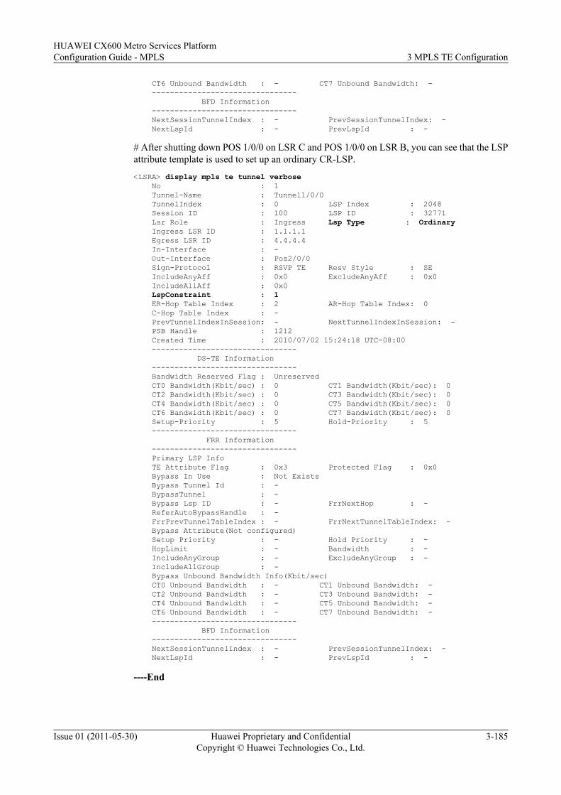
CT6 Unbound Bandwidth : - CT7 Unbound Bandwidth: - -------------------------------- BFD Information -------------------------------- NextSessionTunnelIndex : - PrevSessionTunnelIndex: - NextLspId : - PrevLspId : -
# After shutting down POS 1/0/0 on LSR C and POS 1/0/0 on LSR B, you can see that the LSPattribute template is used to set up an ordinary CR-LSP.
<LSRA> display mpls te tunnel verbose No : 1 Tunnel-Name : Tunnel1/0/0 TunnelIndex : 0 LSP Index : 2048 Session ID : 100 LSP ID : 32771 Lsr Role : Ingress Lsp Type : Ordinary Ingress LSR ID : 1.1.1.1 Egress LSR ID : 4.4.4.4 In-Interface : - Out-Interface : Pos2/0/0 Sign-Protocol : RSVP TE Resv Style : SE IncludeAnyAff : 0x0 ExcludeAnyAff : 0x0 IncludeAllAff : 0x0 LspConstraint : 1 ER-Hop Table Index : 2 AR-Hop Table Index: 0 C-Hop Table Index : - PrevTunnelIndexInSession: - NextTunnelIndexInSession: - PSB Handle : 1212 Created Time : 2010/07/02 15:24:18 UTC-08:00 -------------------------------- DS-TE Information -------------------------------- Bandwidth Reserved Flag : Unreserved CT0 Bandwidth(Kbit/sec) : 0 CT1 Bandwidth(Kbit/sec): 0 CT2 Bandwidth(Kbit/sec) : 0 CT3 Bandwidth(Kbit/sec): 0 CT4 Bandwidth(Kbit/sec) : 0 CT5 Bandwidth(Kbit/sec): 0 CT6 Bandwidth(Kbit/sec) : 0 CT7 Bandwidth(Kbit/sec): 0 Setup-Priority : 5 Hold-Priority : 5 -------------------------------- FRR Information -------------------------------- Primary LSP Info TE Attribute Flag : 0x3 Protected Flag : 0x0 Bypass In Use : Not Exists Bypass Tunnel Id : - BypassTunnel : - Bypass Lsp ID : - FrrNextHop : - ReferAutoBypassHandle : - FrrPrevTunnelTableIndex : - FrrNextTunnelTableIndex: - Bypass Attribute(Not configured) Setup Priority : - Hold Priority : - HopLimit : - Bandwidth : - IncludeAnyGroup : - ExcludeAnyGroup : - IncludeAllGroup : - Bypass Unbound Bandwidth Info(Kbit/sec) CT0 Unbound Bandwidth : - CT1 Unbound Bandwidth: - CT2 Unbound Bandwidth : - CT3 Unbound Bandwidth: - CT4 Unbound Bandwidth : - CT5 Unbound Bandwidth: - CT6 Unbound Bandwidth : - CT7 Unbound Bandwidth: - -------------------------------- BFD Information -------------------------------- NextSessionTunnelIndex : - PrevSessionTunnelIndex: - NextLspId : - PrevLspId : -
----End
HUAWEI CX600 Metro Services PlatformConfiguration Guide - MPLS 3 MPLS TE Configuration
Issue 01 (2011-05-30) Huawei Proprietary and ConfidentialCopyright © Huawei Technologies Co., Ltd.
3-185
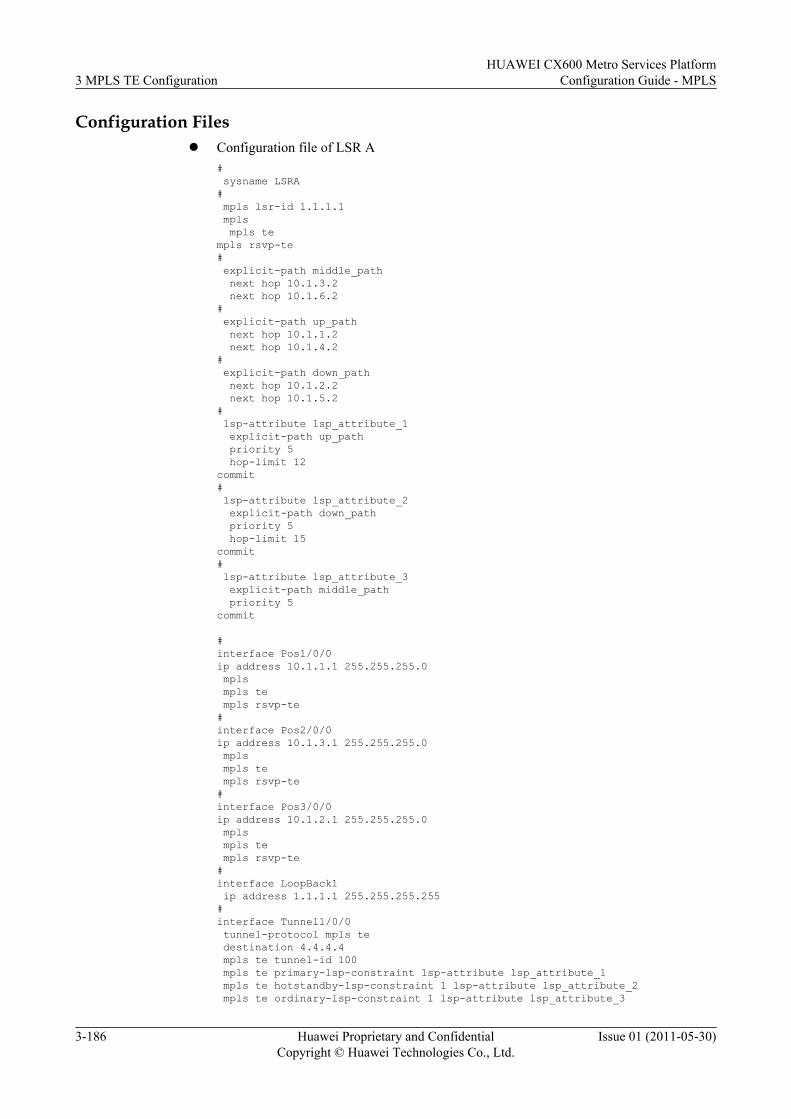
Configuration Filesl Configuration file of LSR A
# sysname LSRA# mpls lsr-id 1.1.1.1 mpls mpls templs rsvp-te# explicit-path middle_path next hop 10.1.3.2 next hop 10.1.6.2# explicit-path up_path next hop 10.1.1.2 next hop 10.1.4.2# explicit-path down_path next hop 10.1.2.2 next hop 10.1.5.2# lsp-attribute lsp_attribute_1 explicit-path up_path priority 5 hop-limit 12commit# lsp-attribute lsp_attribute_2 explicit-path down_path priority 5 hop-limit 15commit# lsp-attribute lsp_attribute_3 explicit-path middle_path priority 5commit
#interface Pos1/0/0ip address 10.1.1.1 255.255.255.0 mpls mpls te mpls rsvp-te#interface Pos2/0/0ip address 10.1.3.1 255.255.255.0 mpls mpls te mpls rsvp-te#interface Pos3/0/0ip address 10.1.2.1 255.255.255.0 mpls mpls te mpls rsvp-te#interface LoopBack1 ip address 1.1.1.1 255.255.255.255#interface Tunnel1/0/0 tunnel-protocol mpls te destination 4.4.4.4 mpls te tunnel-id 100 mpls te primary-lsp-constraint lsp-attribute lsp_attribute_1 mpls te hotstandby-lsp-constraint 1 lsp-attribute lsp_attribute_2 mpls te ordinary-lsp-constraint 1 lsp-attribute lsp_attribute_3
3 MPLS TE ConfigurationHUAWEI CX600 Metro Services Platform
Configuration Guide - MPLS
3-186 Huawei Proprietary and ConfidentialCopyright © Huawei Technologies Co., Ltd.
Issue 01 (2011-05-30)
mpls te commit#ospf 1 opaque-capability enable area 0.0.0.0 network 1.1.1.1 0.0.0.0 network 10.1.1.0 0.0.0.255 network 10.1.2.0 0.0.0.255 network 10.1.3.0 0.0.0.255 mpls-te enable#return
l Configuration file of LSR B# sysname LSRB#mpls lsr-id 10.1.5.1 mpls mpls te mpls rsvp-te#interface Pos1/0/0ip address 10.1.2.2 255.255.255.0 mpls mpls te mpls rsvp-te#interface Pos2/0/0 ip address 10.1.5.1 255.255.255.0 mpls mpls te mpls rsvp-te#ospf 1 opaque-capability enable area 0.0.0.0 network 10.1.2.0 0.0.0.255 network 10.1.5.0 0.0.0.255 mpls-te enable #return
l Configuration file of LSR C# sysname LSRC#mpls lsr-id 10.1.4.1 mpls mpls te mpls rsvp-te#interface Pos1/0/0 ip address 10.1.1.2 255.255.255.0 mpls mpls te mpls rsvp-te#interface Pos2/0/0ip address 10.1.4.1 255.255.255.0 mpls mpls te mpls rsvp-te#ospf 1 opaque-capability enable area 0.0.0.0 network 10.1.1.0 0.0.0.255 network 10.1.4.0 0.0.0.255 mpls-te enable
HUAWEI CX600 Metro Services PlatformConfiguration Guide - MPLS 3 MPLS TE Configuration
Issue 01 (2011-05-30) Huawei Proprietary and ConfidentialCopyright © Huawei Technologies Co., Ltd.
3-187
#return
l Configuration file of LSR D# sysname LSRD# mpls lsr-id 4.4.4.4 mpls mpls te mpls rsvp-te#interface Pos1/0/0ip address 10.1.4.2 255.255.255.0 mpls mpls te mpls rsvp-te#interface Pos2/0/0ip address 10.1.6.2 255.255.255.0 mpls mpls te mpls rsvp-te#interface Pos3/0/0ip address 10.1.5.2 255.255.255.0 mpls mpls te mpls rsvp-te#interface LoopBack1 ip address 4.4.4.4 255.255.255.255#ospf 1 opaque-capability enable area 0.0.0.0 network 4.4.4.4 0.0.0.0 network 10.1.4.0 0.0.0.255 network 10.1.5.0 0.0.0.255 network 10.1.6.0 0.0.0.255 mpls-te enable #return
l Configuration file of LSR E# sysname LSRE# mpls lsr-id 10.1.6.1 mpls mpls templs rsvp-te#interface Pos1/0/0ip address 10.1.3.2 255.255.255.0 mpls mpls te mpls rsvp-te#interface Pos2/0/0ip address 10.1.6.1 255.255.255.0 mpls mpls te mpls rsvp-te#ospf 1 opaque-capability enable area 0.0.0.0 network 10.1.3.0 0.0.0.255 network 10.1.6.0 0.0.0.255
3 MPLS TE ConfigurationHUAWEI CX600 Metro Services Platform
Configuration Guide - MPLS
3-188 Huawei Proprietary and ConfidentialCopyright © Huawei Technologies Co., Ltd.
Issue 01 (2011-05-30)
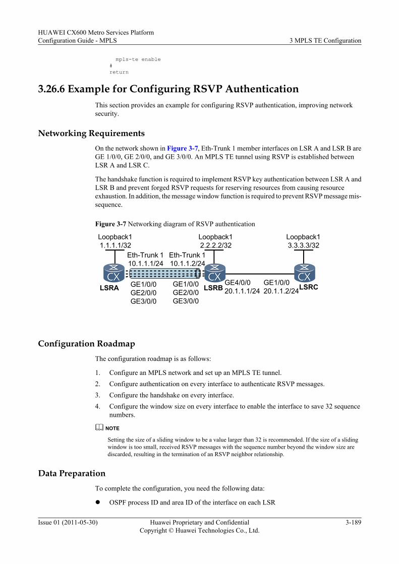
mpls-te enable#return
3.26.6 Example for Configuring RSVP AuthenticationThis section provides an example for configuring RSVP authentication, improving networksecurity.
Networking RequirementsOn the network shown in Figure 3-7, Eth-Trunk 1 member interfaces on LSR A and LSR B areGE 1/0/0, GE 2/0/0, and GE 3/0/0. An MPLS TE tunnel using RSVP is established betweenLSR A and LSR C.
The handshake function is required to implement RSVP key authentication between LSR A andLSR B and prevent forged RSVP requests for reserving resources from causing resourceexhaustion. In addition, the message window function is required to prevent RSVP message mis-sequence.
Figure 3-7 Networking diagram of RSVP authentication
Loopback11.1.1.1/32
Loopback12.2.2.2/32
Loopback13.3.3.3/32
Eth-Trunk 110.1.1.1/24
Eth-Trunk 110.1.1.2/24
GE1/0/0GE2/0/0GE3/0/0
GE1/0/0GE2/0/0GE3/0/0
GE4/0/020.1.1.1/24
GE1/0/020.1.1.2/24LSRA LSRB LSRC
Configuration RoadmapThe configuration roadmap is as follows:
1. Configure an MPLS network and set up an MPLS TE tunnel.2. Configure authentication on every interface to authenticate RSVP messages.3. Configure the handshake on every interface.4. Configure the window size on every interface to enable the interface to save 32 sequence
numbers.
NOTE
Setting the size of a sliding window to be a value larger than 32 is recommended. If the size of a slidingwindow is too small, received RSVP messages with the sequence number beyond the window size arediscarded, resulting in the termination of an RSVP neighbor relationship.
Data PreparationTo complete the configuration, you need the following data:
l OSPF process ID and area ID of the interface on each LSR
HUAWEI CX600 Metro Services PlatformConfiguration Guide - MPLS 3 MPLS TE Configuration
Issue 01 (2011-05-30) Huawei Proprietary and ConfidentialCopyright © Huawei Technologies Co., Ltd.
3-189
l RSVP authentication key and local passwordl Window size for RSVP authentication
ProcedureStep 1 Configure the IP address for each interface.
Configure the IP address and mask of each interface as shown in Figure 3-7. For detailedconfiguration, see configuration files in this example.
Step 2 Configure OSPF.
Configure OSPF on all LSRs to advertise the route to the network segment of each interface andthe host route of each LSR ID. For detailed configuration, see configuration files in this example.
After the configuration, run the display ip routing-table command on each LSR. You can viewthat the LSRs have learned routes from each other.
Step 3 Configure basic MPLS functions and enable MPLS TE, MPLS RSVP-TE, and CSPF.
# Configure LSR A.[LSRA] mpls lsr-id 1.1.1.1[LSRA] mpls[LSRA-mpls] mpls te[LSRA-mpls] mpls rsvp-te[LSRA-mpls] mpls te cspf[LSRA-mpls] quit[LSRA] interface eth-trunk 1[LSRA-Eth-Trunk1] mpls[LSRA-Eth-Trunk1] mpls te[LSRA-Eth-Trunk1] mpls rsvp-te[LSRA-Eth-Trunk1] quit
NOTE
The configurations of LSR B and LSR C are similar to that of LSR A, and are not provided here.
Step 4 Configure OSPF TE.
# Configure LSR A.[LSRA] ospf 1[LSRA-ospf-1] opaque-capability enable[LSRA-ospf-1] area 0[LSRA-ospf-1-area-0.0.0.0] mpls-te enable [LSRA-ospf-1-area-0.0.0.0] quit
# Configure LSR B.[LSRB] ospf 1[LSRB-ospf-1] opaque-capability enable[LSRB-ospf-1] area 0[LSRB-ospf-1-area-0.0.0.0] mpls-te enable [LSRB-ospf-1-area-0.0.0.0] quit
# Configure LSR C.[LSRC] ospf 1[LSRC-ospf-1] opaque-capability enable[LSRC-ospf-1] area 0[LSRC-ospf-1-area-0.0.0.0] mpls-te enable [LSRC-ospf-1-area-0.0.0.0] quit
Step 5 Configure the MPLS TE tunnel.
# Configure the MPLS TE tunnel on LSR A.
3 MPLS TE ConfigurationHUAWEI CX600 Metro Services Platform
Configuration Guide - MPLS
3-190 Huawei Proprietary and ConfidentialCopyright © Huawei Technologies Co., Ltd.
Issue 01 (2011-05-30)
[LSRA] interface tunnel 1/0/0[LSRA-Tunnel1/0/0] ip address unnumbered interface loopback 1[LSRA-Tunnel1/0/0] tunnel-protocol mpls te[LSRA-Tunnel1/0/0] destination 3.3.3.3[LSRA-Tunnel1/0/0] mpls te signal-protocol rsvp-te[LSRA-Tunnel1/0/0] mpls te tunnel-id 1[LSRA-Tunnel1/0/0] mpls te commit[LSRA-Tunnel1/0/0] quit
After the configuration, run the display interface tunnel command on LSR A. You can viewthe tunnel interface is Up.
[LSRA] display interface tunnel 1/0/0Tunnel1/0/0 current state : UPLine protocol current state : UPLast up time: 2007-9-27, 16:38:41Description : Tunnel1/0/0 Interface, Route Port...
Step 6 Configure the RSVP authentication on interfaces of the MPLS TE links on LSR A and LSR B.
# Configure LSR A.
[LSRA] interface eth-trunk 1[LSRA-Eth-Trunk1] mpls rsvp-te authentication plain 123456789[LSRA-Eth-Trunk1] mpls rsvp-te authentication handshake 12345678[LSRA-Eth-Trunk1] mpls rsvp-te authentication window-size 32
# Configure LSR B.
[LSRB] interface eth-trunk 1[LSRB-Eth-Trunk1] mpls rsvp-te authentication plain 123456789[LSRB-Eth-Trunk1] mpls rsvp-te authentication handshake 12345678[LSRB-Eth-Trunk1] mpls rsvp-te authentication window-size 32
Step 7 Verify the configuration.
Run the reset mpls rsvp-te command, and then run the display interface tunnel command onLSR A. You can view that the tunnel interface is Up.
Run the display mpls rsvp-te interface command on LSR A or LSR B. You can viewinformation about RSVP authentication.
[LSRA] display mpls rsvp-te interface eth-trunk 1Interface: Eth-Trunk1 Interface Address: 10.1.1.1 Interface state: UP Interface Index: 0x406 Total-BW: 0 Used-BW: 0 Hello configured: NO Num of Neighbors: 1 SRefresh feature: DISABLE SRefresh Interval: 30 sec Mpls Mtu: 1500 Retransmit Interval: 500 msec Increment Value: 1 Authentication: ENABLE Challenge: ENABLE WindowSize: 32 Next Seq # to be sent:3570642420 4 Key ID: d5d7adf41800 Bfd Enabled: DISABLE Bfd Min-Tx: 10 Bfd Min-Rx: 10 Bfd Detect-Multi: 3
----End
Configuration Filesl Configuration file of LSR A
# sysname LSRA# mpls lsr-id 1.1.1.1
HUAWEI CX600 Metro Services PlatformConfiguration Guide - MPLS 3 MPLS TE Configuration
Issue 01 (2011-05-30) Huawei Proprietary and ConfidentialCopyright © Huawei Technologies Co., Ltd.
3-191
mpls mpls te mpls rsvp-te mpls te cspf#interface Eth-Trunk1 ip address 10.1.1.1 255.255.255.0 mpls mpls te mpls rsvp-te mpls rsvp-te authentication plain 123456789 mpls rsvp-te authentication handshake 12345678 mpls rsvp-te authentication window-size 32#interface GigabitEthernet1/0/0 undo shutdown eth-trunk 1#interface GigabitEthernet2/0/0 undo shutdown eth-trunk 1#interface GigabitEthernet3/0/0 undo shutdown eth-trunk 1#interface LoopBack1 ip address 1.1.1.1 255.255.255.255#interface Tunnel1/0/0 ip address unnumbered interface LoopBack1 tunnel-protocol mpls te destination 3.3.3.3 mpls te tunnel-id 1 mpls te commit#ospf 1 opaque-capability enable area 0.0.0.0 network 10.1.1.0 0.0.0.255 network 1.1.1.1 0.0.0.0 mpls-te enable#return
l Configuration file of LSR B# sysname LSRB# mpls lsr-id 2.2.2.2 mpls mpls te mpls rsvp-te#interface Eth-Trunk1 ip address 10.1.1.2 255.255.255.0 mpls mpls te mpls rsvp-te mpls rsvp-te authentication plain 123456789 mpls rsvp-te authentication handshake 12345678 mpls rsvp-te authentication window-size 32#interface GigabitEthernet1/0/0 undo shutdown eth-trunk 1#interface GigabitEthernet2/0/0 undo shutdown eth-trunk 1
3 MPLS TE ConfigurationHUAWEI CX600 Metro Services Platform
Configuration Guide - MPLS
3-192 Huawei Proprietary and ConfidentialCopyright © Huawei Technologies Co., Ltd.
Issue 01 (2011-05-30)
#interface GigabitEthernet3/0/0 undo shutdown eth-trunk 1#interface GigabitEthernet4/0/0 ip address 20.1.1.1 255.255.255.0 mpls mpls te mpls rsvp-te#interface LoopBack1 ip address 2.2.2.2 255.255.255.255#ospf 1 opaque-capability enable area 0.0.0.0 network 10.1.1.0 0.0.0.255 network 20.1.1.0 0.0.0.255 network 2.2.2.2 0.0.0.0 mpls-te enable#return
l Configuration file of LSR C# sysname LSRC# mpls lsr-id 3.3.3.3 mpls mpls te mpls rsvp-te#interface GigabiEthernet1/0/0 ip address 20.1.1.2 255.255.255.0 mpls mpls te mpls rsvp-te#interface LoopBack1 ip address 3.3.3.3 255.255.255.255#ospf 1 opaque-capability enable area 0.0.0.0 network 20.1.1.0 0.0.0.255 network 3.3.3.3 0.0.0.0 mpls-te enable#Return
3.26.7 Example for Configuring Tunnel PropertiesThis section provides an example for configuring properties of an MPLS TE tunnel, includingthe maximum available bandwidth, maximum reservable bandwidth, and the Color field that isthe administrative group property of each link.
HUAWEI CX600 Metro Services PlatformConfiguration Guide - MPLS 3 MPLS TE Configuration
Issue 01 (2011-05-30) Huawei Proprietary and ConfidentialCopyright © Huawei Technologies Co., Ltd.
3-193
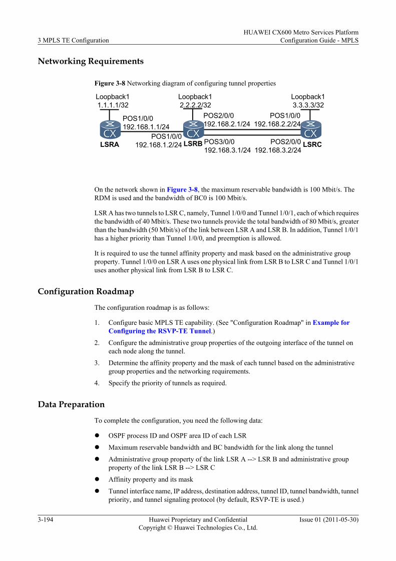
Networking Requirements
Figure 3-8 Networking diagram of configuring tunnel properties
Loopback13.3.3.3/32
Loopback11.1.1.1/32
LSRB
POS1/0/0192.168.1.1/24
POS1/0/0192.168.1.2/24
POS2/0/0192.168.2.1/24
LSRA
Loopback12.2.2.2/32
LSRCPOS2/0/0192.168.3.2/24
POS1/0/0192.168.2.2/24
POS3/0/0192.168.3.1/24
On the network shown in Figure 3-8, the maximum reservable bandwidth is 100 Mbit/s. TheRDM is used and the bandwidth of BC0 is 100 Mbit/s.
LSR A has two tunnels to LSR C, namely, Tunnel 1/0/0 and Tunnel 1/0/1, each of which requiresthe bandwidth of 40 Mbit/s. These two tunnels provide the total bandwidth of 80 Mbit/s, greaterthan the bandwidth (50 Mbit/s) of the link between LSR A and LSR B. In addition, Tunnel 1/0/1has a higher priority than Tunnel 1/0/0, and preemption is allowed.
It is required to use the tunnel affinity property and mask based on the administrative groupproperty. Tunnel 1/0/0 on LSR A uses one physical link from LSR B to LSR C and Tunnel 1/0/1uses another physical link from LSR B to LSR C.
Configuration Roadmap
The configuration roadmap is as follows:
1. Configure basic MPLS TE capability. (See "Configuration Roadmap" in Example forConfiguring the RSVP-TE Tunnel.)
2. Configure the administrative group properties of the outgoing interface of the tunnel oneach node along the tunnel.
3. Determine the affinity property and the mask of each tunnel based on the administrativegroup properties and the networking requirements.
4. Specify the priority of tunnels as required.
Data Preparation
To complete the configuration, you need the following data:
l OSPF process ID and OSPF area ID of each LSR
l Maximum reservable bandwidth and BC bandwidth for the link along the tunnel
l Administrative group property of the link LSR A --> LSR B and administrative groupproperty of the link LSR B --> LSR C
l Affinity property and its mask
l Tunnel interface name, IP address, destination address, tunnel ID, tunnel bandwidth, tunnelpriority, and tunnel signaling protocol (by default, RSVP-TE is used.)
3 MPLS TE ConfigurationHUAWEI CX600 Metro Services Platform
Configuration Guide - MPLS
3-194 Huawei Proprietary and ConfidentialCopyright © Huawei Technologies Co., Ltd.
Issue 01 (2011-05-30)
ProcedureStep 1 Configure IP addresses for the interfaces.
On the network shown in Figure 3-8, configure the IP address and mask for interfaces, includingthe loopback interface.
The detailed configuration is not provided here.
Step 2 Configure the IGP protocol.
Configure OSPF on all LSRs to advertise the route to network segment of each interface andLSR ID.
The detailed configuration is not provided here.
Step 3 Configure the basic MPLS functions, and enable MPLS TE, RSVP-TE, and OSPF TE. EnableCSPF on the ingress.
# Configure the basic MPLS functions, and enable MPLS TE and RSVP-TE on LSR A, LSR B,and LSR C.
Take LSR A as an example.
[LSRA] mpls lsr-id 1.1.1.1[LSRA] mpls[LSRA-mpls] mpls te[LSRA-mpls] mpls rsvp-te[LSRA-mpls] quit[LSRA] interface pos 1/0/0[LSRA-Pos1/0/0] mpls[LSRA-Pos1/0/0] mpls te[LSRA-Pos1/0/0] mpls rsvp-te[LSRA-Pos1/0/0] quit
# Configure OSPF TE on LSR A, LSR B, and LSR C. Use the display on LSR A as an example.
[LSRA] ospf[LSRA-ospf-1] opaque-capability enable[LSRA-ospf-1] area 0[LSRA-ospf-1-area-0.0.0.0] mpls-te enable[LSRA-ospf-1-area-0.0.0.0] quit[LSRA-ospf-1] quit
The configurations of LSR B and LSR C are similar to that of LSR A, and are not provided here.
# Enable CSPF on LSR A, the ingress node.
[LSRA] mpls[LSRA-mpls] mpls te cspf[LSRA-mpls] quit
Step 4 Configure MPLS TE properties for the links.
# Set the maximum reservable bandwidth to 100 Mbit/s, and the BC0 bandwidth to 100 Mbit/s.
[LSRA] interface pos 1/0/0[LSRA-Pos1/0/0] mpls te bandwidth max-reservable-bandwidth 100000[LSRA-Pos1/0/0] mpls te bandwidth bc0 100000
# Set the administrative group property to 0x10001 for the link on LSR A.
[LSRA-Pos1/0/0] mpls te link administrative group 10001[LSRA-Pos1/0/0] quit
# Set the MPLS TE properties for the links on LSR B.
HUAWEI CX600 Metro Services PlatformConfiguration Guide - MPLS 3 MPLS TE Configuration
Issue 01 (2011-05-30) Huawei Proprietary and ConfidentialCopyright © Huawei Technologies Co., Ltd.
3-195
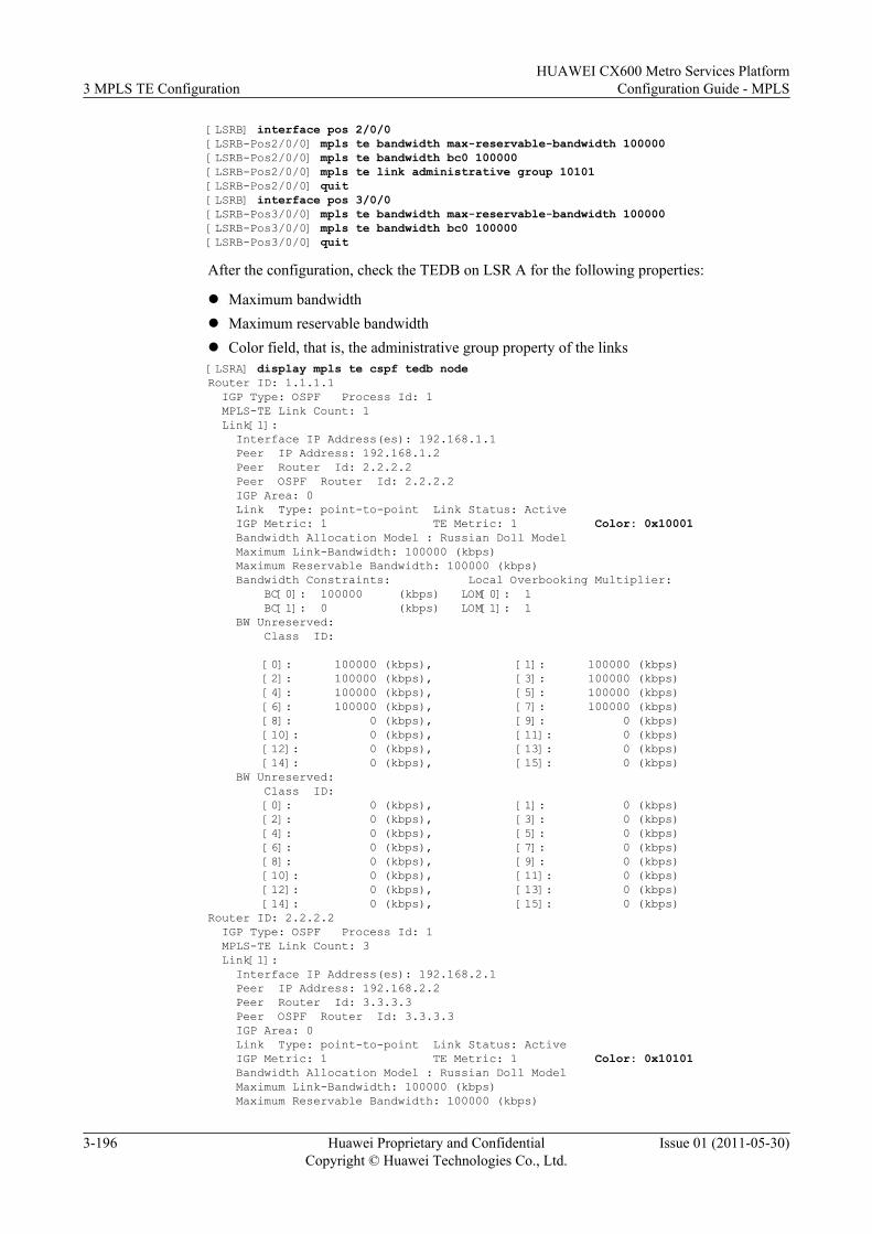
[LSRB] interface pos 2/0/0[LSRB-Pos2/0/0] mpls te bandwidth max-reservable-bandwidth 100000[LSRB-Pos2/0/0] mpls te bandwidth bc0 100000[LSRB-Pos2/0/0] mpls te link administrative group 10101[LSRB-Pos2/0/0] quit[LSRB] interface pos 3/0/0[LSRB-Pos3/0/0] mpls te bandwidth max-reservable-bandwidth 100000[LSRB-Pos3/0/0] mpls te bandwidth bc0 100000[LSRB-Pos3/0/0] quit
After the configuration, check the TEDB on LSR A for the following properties:
l Maximum bandwidthl Maximum reservable bandwidthl Color field, that is, the administrative group property of the links[LSRA] display mpls te cspf tedb nodeRouter ID: 1.1.1.1 IGP Type: OSPF Process Id: 1 MPLS-TE Link Count: 1 Link[1]: Interface IP Address(es): 192.168.1.1 Peer IP Address: 192.168.1.2 Peer Router Id: 2.2.2.2 Peer OSPF Router Id: 2.2.2.2 IGP Area: 0 Link Type: point-to-point Link Status: Active IGP Metric: 1 TE Metric: 1 Color: 0x10001 Bandwidth Allocation Model : Russian Doll Model Maximum Link-Bandwidth: 100000 (kbps) Maximum Reservable Bandwidth: 100000 (kbps) Bandwidth Constraints: Local Overbooking Multiplier: BC[0]: 100000 (kbps) LOM[0]: 1 BC[1]: 0 (kbps) LOM[1]: 1 BW Unreserved: Class ID:
[0]: 100000 (kbps), [1]: 100000 (kbps) [2]: 100000 (kbps), [3]: 100000 (kbps) [4]: 100000 (kbps), [5]: 100000 (kbps) [6]: 100000 (kbps), [7]: 100000 (kbps) [8]: 0 (kbps), [9]: 0 (kbps) [10]: 0 (kbps), [11]: 0 (kbps) [12]: 0 (kbps), [13]: 0 (kbps) [14]: 0 (kbps), [15]: 0 (kbps) BW Unreserved: Class ID: [0]: 0 (kbps), [1]: 0 (kbps) [2]: 0 (kbps), [3]: 0 (kbps) [4]: 0 (kbps), [5]: 0 (kbps) [6]: 0 (kbps), [7]: 0 (kbps) [8]: 0 (kbps), [9]: 0 (kbps) [10]: 0 (kbps), [11]: 0 (kbps) [12]: 0 (kbps), [13]: 0 (kbps) [14]: 0 (kbps), [15]: 0 (kbps)Router ID: 2.2.2.2 IGP Type: OSPF Process Id: 1 MPLS-TE Link Count: 3 Link[1]: Interface IP Address(es): 192.168.2.1 Peer IP Address: 192.168.2.2 Peer Router Id: 3.3.3.3 Peer OSPF Router Id: 3.3.3.3 IGP Area: 0 Link Type: point-to-point Link Status: Active IGP Metric: 1 TE Metric: 1 Color: 0x10101 Bandwidth Allocation Model : Russian Doll Model Maximum Link-Bandwidth: 100000 (kbps) Maximum Reservable Bandwidth: 100000 (kbps)
3 MPLS TE ConfigurationHUAWEI CX600 Metro Services Platform
Configuration Guide - MPLS
3-196 Huawei Proprietary and ConfidentialCopyright © Huawei Technologies Co., Ltd.
Issue 01 (2011-05-30)
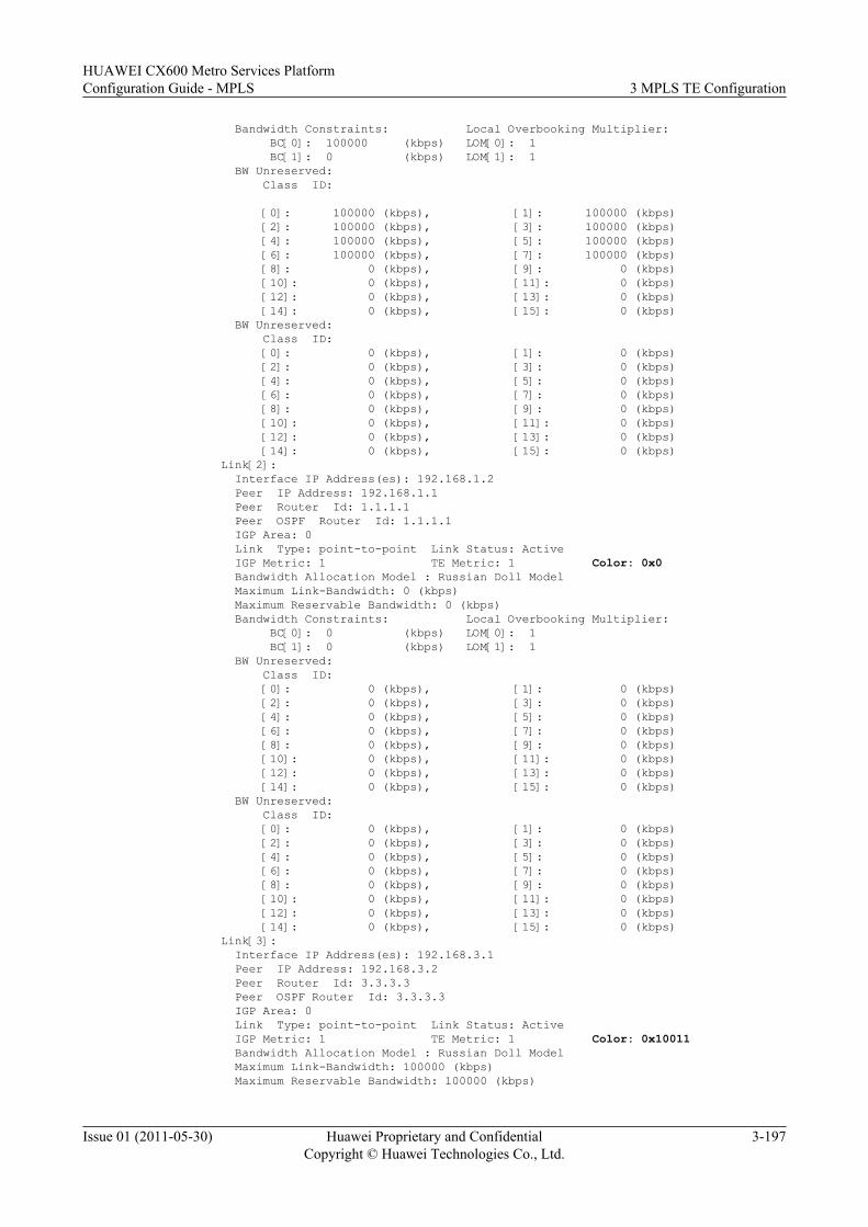
Bandwidth Constraints: Local Overbooking Multiplier: BC[0]: 100000 (kbps) LOM[0]: 1 BC[1]: 0 (kbps) LOM[1]: 1 BW Unreserved: Class ID:
[0]: 100000 (kbps), [1]: 100000 (kbps) [2]: 100000 (kbps), [3]: 100000 (kbps) [4]: 100000 (kbps), [5]: 100000 (kbps) [6]: 100000 (kbps), [7]: 100000 (kbps) [8]: 0 (kbps), [9]: 0 (kbps) [10]: 0 (kbps), [11]: 0 (kbps) [12]: 0 (kbps), [13]: 0 (kbps) [14]: 0 (kbps), [15]: 0 (kbps) BW Unreserved: Class ID: [0]: 0 (kbps), [1]: 0 (kbps) [2]: 0 (kbps), [3]: 0 (kbps) [4]: 0 (kbps), [5]: 0 (kbps) [6]: 0 (kbps), [7]: 0 (kbps) [8]: 0 (kbps), [9]: 0 (kbps) [10]: 0 (kbps), [11]: 0 (kbps) [12]: 0 (kbps), [13]: 0 (kbps) [14]: 0 (kbps), [15]: 0 (kbps) Link[2]: Interface IP Address(es): 192.168.1.2 Peer IP Address: 192.168.1.1 Peer Router Id: 1.1.1.1 Peer OSPF Router Id: 1.1.1.1 IGP Area: 0 Link Type: point-to-point Link Status: Active IGP Metric: 1 TE Metric: 1 Color: 0x0 Bandwidth Allocation Model : Russian Doll Model Maximum Link-Bandwidth: 0 (kbps) Maximum Reservable Bandwidth: 0 (kbps) Bandwidth Constraints: Local Overbooking Multiplier: BC[0]: 0 (kbps) LOM[0]: 1 BC[1]: 0 (kbps) LOM[1]: 1 BW Unreserved: Class ID: [0]: 0 (kbps), [1]: 0 (kbps) [2]: 0 (kbps), [3]: 0 (kbps) [4]: 0 (kbps), [5]: 0 (kbps) [6]: 0 (kbps), [7]: 0 (kbps) [8]: 0 (kbps), [9]: 0 (kbps) [10]: 0 (kbps), [11]: 0 (kbps) [12]: 0 (kbps), [13]: 0 (kbps) [14]: 0 (kbps), [15]: 0 (kbps) BW Unreserved: Class ID: [0]: 0 (kbps), [1]: 0 (kbps) [2]: 0 (kbps), [3]: 0 (kbps) [4]: 0 (kbps), [5]: 0 (kbps) [6]: 0 (kbps), [7]: 0 (kbps) [8]: 0 (kbps), [9]: 0 (kbps) [10]: 0 (kbps), [11]: 0 (kbps) [12]: 0 (kbps), [13]: 0 (kbps) [14]: 0 (kbps), [15]: 0 (kbps) Link[3]: Interface IP Address(es): 192.168.3.1 Peer IP Address: 192.168.3.2 Peer Router Id: 3.3.3.3 Peer OSPF Router Id: 3.3.3.3 IGP Area: 0 Link Type: point-to-point Link Status: Active IGP Metric: 1 TE Metric: 1 Color: 0x10011 Bandwidth Allocation Model : Russian Doll Model Maximum Link-Bandwidth: 100000 (kbps) Maximum Reservable Bandwidth: 100000 (kbps)
HUAWEI CX600 Metro Services PlatformConfiguration Guide - MPLS 3 MPLS TE Configuration
Issue 01 (2011-05-30) Huawei Proprietary and ConfidentialCopyright © Huawei Technologies Co., Ltd.
3-197
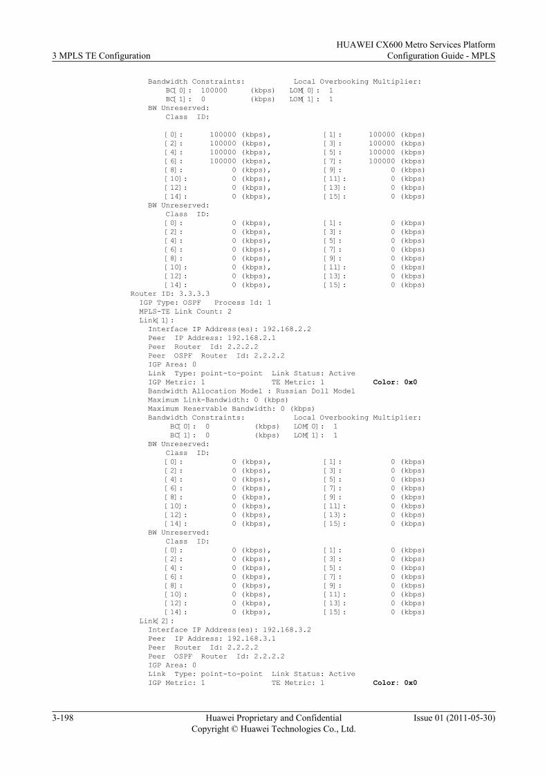
Bandwidth Constraints: Local Overbooking Multiplier: BC[0]: 100000 (kbps) LOM[0]: 1 BC[1]: 0 (kbps) LOM[1]: 1 BW Unreserved: Class ID:
[0]: 100000 (kbps), [1]: 100000 (kbps) [2]: 100000 (kbps), [3]: 100000 (kbps) [4]: 100000 (kbps), [5]: 100000 (kbps) [6]: 100000 (kbps), [7]: 100000 (kbps) [8]: 0 (kbps), [9]: 0 (kbps) [10]: 0 (kbps), [11]: 0 (kbps) [12]: 0 (kbps), [13]: 0 (kbps) [14]: 0 (kbps), [15]: 0 (kbps) BW Unreserved: Class ID: [0]: 0 (kbps), [1]: 0 (kbps) [2]: 0 (kbps), [3]: 0 (kbps) [4]: 0 (kbps), [5]: 0 (kbps) [6]: 0 (kbps), [7]: 0 (kbps) [8]: 0 (kbps), [9]: 0 (kbps) [10]: 0 (kbps), [11]: 0 (kbps) [12]: 0 (kbps), [13]: 0 (kbps) [14]: 0 (kbps), [15]: 0 (kbps)Router ID: 3.3.3.3 IGP Type: OSPF Process Id: 1 MPLS-TE Link Count: 2 Link[1]: Interface IP Address(es): 192.168.2.2 Peer IP Address: 192.168.2.1 Peer Router Id: 2.2.2.2 Peer OSPF Router Id: 2.2.2.2 IGP Area: 0 Link Type: point-to-point Link Status: Active IGP Metric: 1 TE Metric: 1 Color: 0x0 Bandwidth Allocation Model : Russian Doll Model Maximum Link-Bandwidth: 0 (kbps) Maximum Reservable Bandwidth: 0 (kbps) Bandwidth Constraints: Local Overbooking Multiplier: BC[0]: 0 (kbps) LOM[0]: 1 BC[1]: 0 (kbps) LOM[1]: 1 BW Unreserved: Class ID: [0]: 0 (kbps), [1]: 0 (kbps) [2]: 0 (kbps), [3]: 0 (kbps) [4]: 0 (kbps), [5]: 0 (kbps) [6]: 0 (kbps), [7]: 0 (kbps) [8]: 0 (kbps), [9]: 0 (kbps) [10]: 0 (kbps), [11]: 0 (kbps) [12]: 0 (kbps), [13]: 0 (kbps) [14]: 0 (kbps), [15]: 0 (kbps) BW Unreserved: Class ID: [0]: 0 (kbps), [1]: 0 (kbps) [2]: 0 (kbps), [3]: 0 (kbps) [4]: 0 (kbps), [5]: 0 (kbps) [6]: 0 (kbps), [7]: 0 (kbps) [8]: 0 (kbps), [9]: 0 (kbps) [10]: 0 (kbps), [11]: 0 (kbps) [12]: 0 (kbps), [13]: 0 (kbps) [14]: 0 (kbps), [15]: 0 (kbps) Link[2]: Interface IP Address(es): 192.168.3.2 Peer IP Address: 192.168.3.1 Peer Router Id: 2.2.2.2 Peer OSPF Router Id: 2.2.2.2 IGP Area: 0 Link Type: point-to-point Link Status: Active IGP Metric: 1 TE Metric: 1 Color: 0x0
3 MPLS TE ConfigurationHUAWEI CX600 Metro Services Platform
Configuration Guide - MPLS
3-198 Huawei Proprietary and ConfidentialCopyright © Huawei Technologies Co., Ltd.
Issue 01 (2011-05-30)
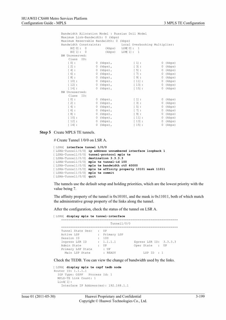
Bandwidth Allocation Model : Russian Doll Model Maximum Link-Bandwidth: 0 (kbps) Maximum Reservable Bandwidth: 0 (kbps) Bandwidth Constraints: Local Overbooking Multiplier: BC[0]: 0 (kbps) LOM[0]: 1 BC[1]: 0 (kbps) LOM[1]: 1 BW Unreserved: Class ID: [0]: 0 (kbps), [1]: 0 (kbps) [2]: 0 (kbps), [3]: 0 (kbps) [4]: 0 (kbps), [5]: 0 (kbps) [6]: 0 (kbps), [7]: 0 (kbps) [8]: 0 (kbps), [9]: 0 (kbps) [10]: 0 (kbps), [11]: 0 (kbps) [12]: 0 (kbps), [13]: 0 (kbps) [14]: 0 (kbps), [15]: 0 (kbps) BW Unreserved: Class ID: [0]: 0 (kbps), [1]: 0 (kbps) [2]: 0 (kbps), [3]: 0 (kbps) [4]: 0 (kbps), [5]: 0 (kbps) [6]: 0 (kbps), [7]: 0 (kbps) [8]: 0 (kbps), [9]: 0 (kbps) [10]: 0 (kbps), [11]: 0 (kbps) [12]: 0 (kbps), [13]: 0 (kbps) [14]: 0 (kbps), [15]: 0 (kbps)
Step 5 Create MPLS TE tunnels.
# Create Tunnel 1/0/0 on LSR A.
[LSRA] interface tunnel 1/0/0[LSRA-Tunnel1/0/0] ip address unnumbered interface loopback 1[LSRA-Tunnel1/0/0] tunnel-protocol mpls te[LSRA-Tunnel1/0/0] destination 3.3.3.3[LSRA-Tunnel1/0/0] mpls te tunnel-id 100[LSRA-Tunnel1/0/0] mpls te bandwidth ct0 40000[LSRA-Tunnel1/0/0] mpls te affinity property 10101 mask 11011[LSRA-Tunnel1/0/0] mpls te commit[LSRA-Tunnel1/0/0] quit
The tunnels use the default setup and holding priorities, which are the lowest priority with thevalue being 7.
The affinity property of the tunnel is 0x10101, and the mask is 0x11011, both of which matchthe administrative group property of the links along the tunnel.
After the configuration, check the status of the tunnel on LSR A.
[LSRA] display mpls te tunnel-interface ================================================================ Tunnel1/0/0 ================================================================ Tunnel State Desc : UP Active LSP : Primary LSP Session ID : 100 Ingress LSR ID : 1.1.1.1 Egress LSR ID: 3.3.3.3 Admin State : UP Oper State : UP Primary LSP State : UP Main LSP State : READY LSP ID : 1
Check the TEDB. You can view the change of bandwidth used by the links.
[LSRA] display mpls te cspf tedb nodeRouter ID: 1.1.1.1 IGP Type: OSPF Process Id: 1 MPLS-TE Link Count: 1 Link[1]: Interface IP Address(es): 192.168.1.1
HUAWEI CX600 Metro Services PlatformConfiguration Guide - MPLS 3 MPLS TE Configuration
Issue 01 (2011-05-30) Huawei Proprietary and ConfidentialCopyright © Huawei Technologies Co., Ltd.
3-199
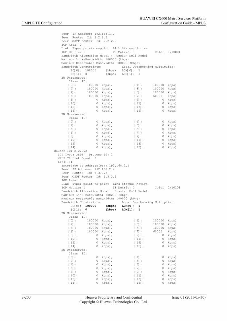
Peer IP Address: 192.168.1.2 Peer Router Id: 2.2.2.2 Peer OSPF Router Id: 2.2.2.2 IGP Area: 0 Link Type: point-to-point Link Status: Active IGP Metric: 1 TE Metric: 1 Color: 0x10001 Bandwidth Allocation Model : Russian Doll Model Maximum Link-Bandwidth: 100000 (kbps) Maximum Reservable Bandwidth: 100000 (kbps) Bandwidth Constraints: Local Overbooking Multiplier: BC[0]: 100000 (kbps) LOM[0]: 1 BC[1]: 0 (kbps) LOM[1]: 1 BW Unreserved: Class ID: [0]: 100000 (kbps), [1]: 100000 (kbps) [2]: 100000 (kbps), [3]: 100000 (kbps) [4]: 100000 (kbps), [5]: 100000 (kbps) [6]: 100000 (kbps), [7]: 60000 (kbps) [8]: 0 (kbps), [9]: 0 (kbps) [10]: 0 (kbps), [11]: 0 (kbps) [12]: 0 (kbps), [13]: 0 (kbps) [14]: 0 (kbps), [15]: 0 (kbps) BW Unreserved: Class ID: [0]: 0 (kbps), [1]: 0 (kbps) [2]: 0 (kbps), [3]: 0 (kbps) [4]: 0 (kbps), [5]: 0 (kbps) [6]: 0 (kbps), [7]: 0 (kbps) [8]: 0 (kbps), [9]: 0 (kbps) [10]: 0 (kbps), [11]: 0 (kbps) [12]: 0 (kbps), [13]: 0 (kbps) [14]: 0 (kbps), [15]: 0 (kbps)Router ID: 2.2.2.2 IGP Type: OSPF Process Id: 1 MPLS-TE Link Count: 3 Link[1]: Interface IP Address(es): 192.168.2.1 Peer IP Address: 192.168.2.2 Peer Router Id: 3.3.3.3 Peer OSPF Router Id: 3.3.3.3 IGP Area: 0 Link Type: point-to-point Link Status: Active IGP Metric: 1 TE Metric: 1 Color: 0x10101 Bandwidth Allocation Model : Russian Doll Model Maximum Link-Bandwidth: 100000 (kbps) Maximum Reservable Bandwidth: 100000 (kbps) Bandwidth Constraints: Local Overbooking Multiplier: BC[0]: 100000 (kbps) LOM[0]: 1 BC[1]: 0 (kbps) LOM[1]: 1 BW Unreserved: Class ID: [0]: 100000 (kbps), [1]: 100000 (kbps) [2]: 100000 (kbps), [3]: 100000 (kbps) [4]: 100000 (kbps), [5]: 100000 (kbps) [6]: 100000 (kbps), [7]: 60000 (kbps) [8]: 0 (kbps), [9]: 0 (kbps) [10]: 0 (kbps), [11]: 0 (kbps) [12]: 0 (kbps), [13]: 0 (kbps) [14]: 0 (kbps), [15]: 0 (kbps) BW Unreserved: Class ID: [0]: 0 (kbps), [1]: 0 (kbps) [2]: 0 (kbps), [3]: 0 (kbps) [4]: 0 (kbps), [5]: 0 (kbps) [6]: 0 (kbps), [7]: 0 (kbps) [8]: 0 (kbps), [9]: 0 (kbps) [10]: 0 (kbps), [11]: 0 (kbps) [12]: 0 (kbps), [13]: 0 (kbps) [14]: 0 (kbps), [15]: 0 (kbps)
3 MPLS TE ConfigurationHUAWEI CX600 Metro Services Platform
Configuration Guide - MPLS
3-200 Huawei Proprietary and ConfidentialCopyright © Huawei Technologies Co., Ltd.
Issue 01 (2011-05-30)
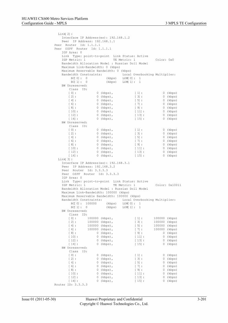
Link[2]: Interface IP Address(es): 192.168.1.2 Peer IP Address: 192.168.1.1Peer Router Id: 1.1.1.1Peer OSPF Router Id: 1.1.1.1 IGP Area: 0 Link Type: point-to-point Link Status: Active IGP Metric: 1 TE Metric: 1 Color: 0x0 Bandwidth Allocation Model : Russian Doll Model Maximum Link-Bandwidth: 0 (kbps) Maximum Reservable Bandwidth: 0 (kbps) Bandwidth Constraints: Local Overbooking Multiplier: BC[0]: 0 (kbps) LOM[0]: 1 BC[1]: 0 (kbps) LOM[1]: 1 BW Unreserved: Class ID: [0]: 0 (kbps), [1]: 0 (kbps) [2]: 0 (kbps), [3]: 0 (kbps) [4]: 0 (kbps), [5]: 0 (kbps) [6]: 0 (kbps), [7]: 0 (kbps) [8]: 0 (kbps), [9]: 0 (kbps) [10]: 0 (kbps), [11]: 0 (kbps) [12]: 0 (kbps), [13]: 0 (kbps) [14]: 0 (kbps), [15]: 0 (kbps) BW Unreserved: Class ID: [0]: 0 (kbps), [1]: 0 (kbps) [2]: 0 (kbps), [3]: 0 (kbps) [4]: 0 (kbps), [5]: 0 (kbps) [6]: 0 (kbps), [7]: 0 (kbps) [8]: 0 (kbps), [9]: 0 (kbps) [10]: 0 (kbps), [11]: 0 (kbps) [12]: 0 (kbps), [13]: 0 (kbps) [14]: 0 (kbps), [15]: 0 (kbps) Link[3]: Interface IP Address(es): 192.168.3.1 Peer IP Address: 192.168.3.2 Peer Router Id: 3.3.3.3 Peer OSPF Router Id: 3.3.3.3 IGP Area: 0 Link Type: point-to-point Link Status: Active IGP Metric: 1 TE Metric: 1 Color: 0x10011 Bandwidth Allocation Model : Russian Doll Model Maximum Link-Bandwidth: 100000 (kbps) Maximum Reservable Bandwidth: 100000 (kbps) Bandwidth Constraints: Local Overbooking Multiplier: BC[0]: 100000 (kbps) LOM[0]: 1 BC[1]: 0 (kbps) LOM[1]: 1 BW Unreserved: Class ID: [0]: 100000 (kbps), [1]: 100000 (kbps) [2]: 100000 (kbps), [3]: 100000 (kbps) [4]: 100000 (kbps), [5]: 100000 (kbps) [6]: 100000 (kbps), [7]: 100000 (kbps) [8]: 0 (kbps), [9]: 0 (kbps) [10]: 0 (kbps), [11]: 0 (kbps) [12]: 0 (kbps), [13]: 0 (kbps) [14]: 0 (kbps), [15]: 0 (kbps) BW Unreserved: Class ID: [0]: 0 (kbps), [1]: 0 (kbps) [2]: 0 (kbps), [3]: 0 (kbps) [4]: 0 (kbps), [5]: 0 (kbps) [6]: 0 (kbps), [7]: 0 (kbps) [8]: 0 (kbps), [9]: 0 (kbps) [10]: 0 (kbps), [11]: 0 (kbps) [12]: 0 (kbps), [13]: 0 (kbps) [14]: 0 (kbps), [15]: 0 (kbps)Router ID: 3.3.3.3
HUAWEI CX600 Metro Services PlatformConfiguration Guide - MPLS 3 MPLS TE Configuration
Issue 01 (2011-05-30) Huawei Proprietary and ConfidentialCopyright © Huawei Technologies Co., Ltd.
3-201
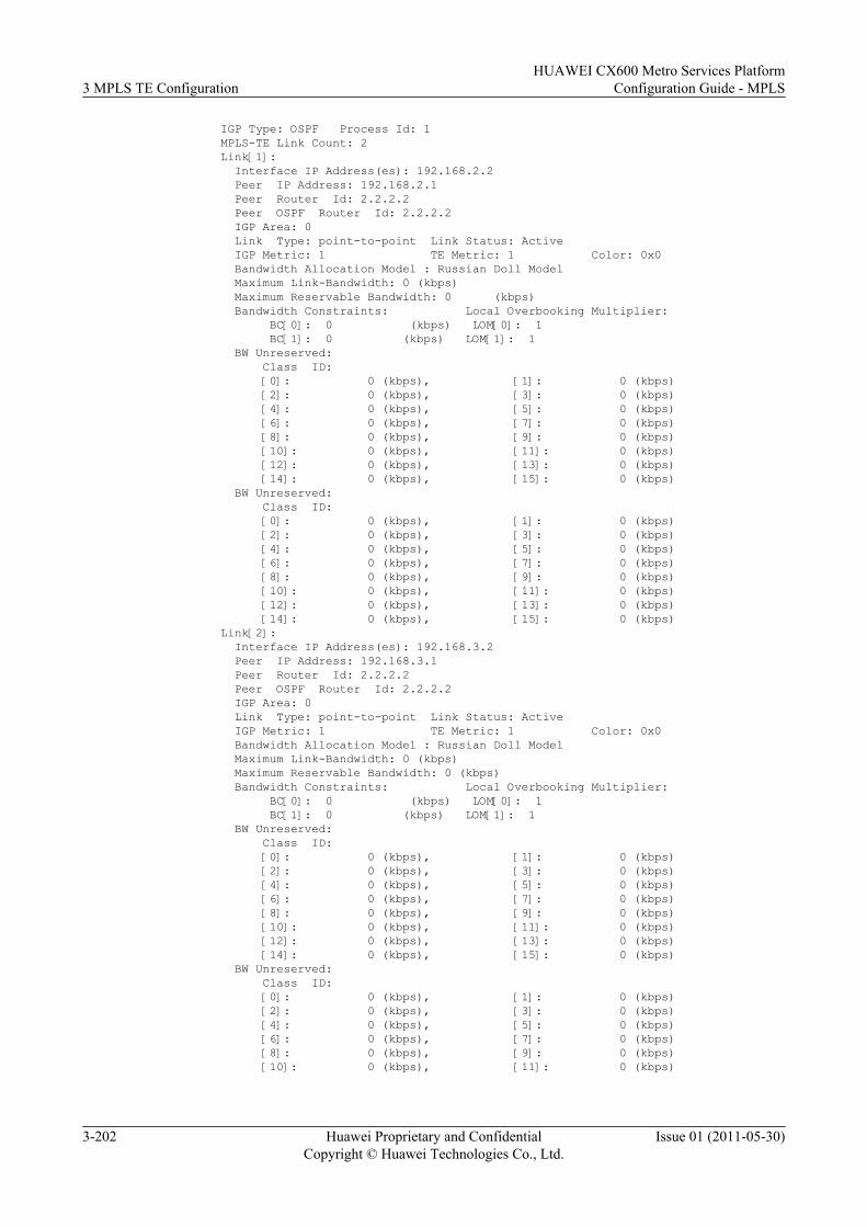
IGP Type: OSPF Process Id: 1 MPLS-TE Link Count: 2 Link[1]: Interface IP Address(es): 192.168.2.2 Peer IP Address: 192.168.2.1 Peer Router Id: 2.2.2.2 Peer OSPF Router Id: 2.2.2.2 IGP Area: 0 Link Type: point-to-point Link Status: Active IGP Metric: 1 TE Metric: 1 Color: 0x0 Bandwidth Allocation Model : Russian Doll Model Maximum Link-Bandwidth: 0 (kbps) Maximum Reservable Bandwidth: 0 (kbps) Bandwidth Constraints: Local Overbooking Multiplier: BC[0]: 0 (kbps) LOM[0]: 1 BC[1]: 0 (kbps) LOM[1]: 1 BW Unreserved: Class ID: [0]: 0 (kbps), [1]: 0 (kbps) [2]: 0 (kbps), [3]: 0 (kbps) [4]: 0 (kbps), [5]: 0 (kbps) [6]: 0 (kbps), [7]: 0 (kbps) [8]: 0 (kbps), [9]: 0 (kbps) [10]: 0 (kbps), [11]: 0 (kbps) [12]: 0 (kbps), [13]: 0 (kbps) [14]: 0 (kbps), [15]: 0 (kbps) BW Unreserved: Class ID: [0]: 0 (kbps), [1]: 0 (kbps) [2]: 0 (kbps), [3]: 0 (kbps) [4]: 0 (kbps), [5]: 0 (kbps) [6]: 0 (kbps), [7]: 0 (kbps) [8]: 0 (kbps), [9]: 0 (kbps) [10]: 0 (kbps), [11]: 0 (kbps) [12]: 0 (kbps), [13]: 0 (kbps) [14]: 0 (kbps), [15]: 0 (kbps) Link[2]: Interface IP Address(es): 192.168.3.2 Peer IP Address: 192.168.3.1 Peer Router Id: 2.2.2.2 Peer OSPF Router Id: 2.2.2.2 IGP Area: 0 Link Type: point-to-point Link Status: Active IGP Metric: 1 TE Metric: 1 Color: 0x0 Bandwidth Allocation Model : Russian Doll Model Maximum Link-Bandwidth: 0 (kbps) Maximum Reservable Bandwidth: 0 (kbps) Bandwidth Constraints: Local Overbooking Multiplier: BC[0]: 0 (kbps) LOM[0]: 1 BC[1]: 0 (kbps) LOM[1]: 1 BW Unreserved: Class ID: [0]: 0 (kbps), [1]: 0 (kbps) [2]: 0 (kbps), [3]: 0 (kbps) [4]: 0 (kbps), [5]: 0 (kbps) [6]: 0 (kbps), [7]: 0 (kbps) [8]: 0 (kbps), [9]: 0 (kbps) [10]: 0 (kbps), [11]: 0 (kbps) [12]: 0 (kbps), [13]: 0 (kbps) [14]: 0 (kbps), [15]: 0 (kbps) BW Unreserved: Class ID: [0]: 0 (kbps), [1]: 0 (kbps) [2]: 0 (kbps), [3]: 0 (kbps) [4]: 0 (kbps), [5]: 0 (kbps) [6]: 0 (kbps), [7]: 0 (kbps) [8]: 0 (kbps), [9]: 0 (kbps) [10]: 0 (kbps), [11]: 0 (kbps)
3 MPLS TE ConfigurationHUAWEI CX600 Metro Services Platform
Configuration Guide - MPLS
3-202 Huawei Proprietary and ConfidentialCopyright © Huawei Technologies Co., Ltd.
Issue 01 (2011-05-30)
[12]: 0 (kbps), [13]: 0 (kbps) [14]: 0 (kbps), [15]: 0 (kbps)
BW Unreserved for Class type 0 indicates the available bandwidth from the maximumreservable bandwidth for various priorities. The command output shows that the unreservedbandwidth changes for CT 7 on the outgoing interfaces on each LSR along the tunnel. Thismeans that some tunnels succeed in reserving 40 Mbit/s bandwidth with the priority being 7.The bandwidth allocation also shows the path that the tunnel uses. This indicates that the affinityproperty and the mask of the tunnel must match the administrative group property of the links.
Run the display mpls te tunnel command on LSR B. You can view the outgoing interface ofthe tunnel.
[LSRB] display mpls te tunnelLSP-Id Destination In/Out-If1.1.1.1:100:1 3.3.3.3 Pos1/0/0/Pos2/0/0
# Create Tunnel 1/0/1 on LSR A.
[LSRA] interface tunnel 1/0/1[LSRA-Tunnel1/0/1] ip address unnumbered interface loopback 1[LSRA-Tunnel1/0/1] tunnel-protocol mpls te[LSRA-Tunnel1/0/1] destination 3.3.3.3[LSRA-Tunnel1/0/1] mpls te tunnel-id 101[LSRA-Tunnel1/0/1] mpls te bandwidth ct0 40000[LSRA-Tunnel1/0/1] mpls te affinity property 10011 mask 11101[LSRA-Tunnel1/0/1] mpls te priority 6[LSRA-Tunnel1/0/1] mpls te commit[LSRA-Tunnel1/0/1] quit
Step 6 Verify the configuration.
After the configuration, run the display interface Tunnel or display mpls te tunnel-interface command to check the status of the tunnel on LSR A. You can view that the status ofTunnel 1/0/0 is Down. This is because the maximum reservable bandwidth of the physical link(LSR A --> LSR B) is not enough, and the bandwidth of Tunnel 1/0/0 is preempted by Tunnel1/0/1 with a higher priority.
Run the display mpls te cspf tedb node command to check the TEDB and the changes ofbandwidth used on the links. The command output proves that Tunnel 1/0/1 passes by POS 3/0/0on LSR B.
Run the display mpls te tunnel command on LSR B. You can view the outgoing interface ofthe tunnel.
[LSRB] display mpls te tunnelLSP-Id Destination In/Out-If1.1.1.1:101:1 3.3.3.3 Pos1/0/0/Pos3/0/0
----End
Configuration Filesl Configuration file of LSR A
# sysname LSRA# mpls lsr-id 1.1.1.1 mpls mpls te mpls rsvp-te mpls te cspf#interface Pos1/0/0
HUAWEI CX600 Metro Services PlatformConfiguration Guide - MPLS 3 MPLS TE Configuration
Issue 01 (2011-05-30) Huawei Proprietary and ConfidentialCopyright © Huawei Technologies Co., Ltd.
3-203
link-protocol ppp ip address 192.168.1.1 255.255.255.0 mpls mpls te mpls te link administrative group 10001 mpls te bandwidth max-reservable-bandwidth 100000 mpls te bandwidth bc0 100000 mpls rsvp-te#interface LoopBack1 ip address 1.1.1.1 255.255.255.255#interface Tunnel1/0/0 ip address unnumbered interface LoopBack1 tunnel-protocol mpls te destination 3.3.3.3 mpls te tunnel-id 100 mpls te bandwidth ct0 40000 mpls te affinity property 10101 mask 11011 mpls te commit#interface Tunnel1/0/1 ip address unnumbered interface LoopBack1 tunnel-protocol mpls te destination 3.3.3.3 mpls te tunnel-id 101 mpls te bandwidth ct0 40000 mpls te priority 6 mpls te affinity property 10001 mask 11101 mpls te commit#ospf 1 opaque-capability enable area 0.0.0.0 network 1.1.1.1 0.0.0.0 network 192.168.1.0 0.0.0.255 mpls-te enable#return
l Configuration file of LSR B# sysname LSRB# mpls lsr-id 2.2.2.2 mpls mpls te mpls rsvp-te#interface Pos1/0/0 link-protocol ppp ip address 192.168.1.2 255.255.255.0 mpls mpls te mpls rsvp-te#interface Pos2/0/0 link-protocol ppp ip address 192.168.2.1 255.255.255.0 mpls mpls te mpls te link administrative group 10101 mpls te bandwidth max-reservable-bandwidth 100000 mpls te bandwidth bc0 100000 mpls rsvp-te#interface Pos3/0/0 link-protocol ppp ip address 192.168.3.1 255.255.255.0 mpls
3 MPLS TE ConfigurationHUAWEI CX600 Metro Services Platform
Configuration Guide - MPLS
3-204 Huawei Proprietary and ConfidentialCopyright © Huawei Technologies Co., Ltd.
Issue 01 (2011-05-30)
mpls te mpls te link administrative group 10011 mpls te bandwidth max-reservable-bandwidth 100000 mpls te bandwidth bc0 100000 mpls rsvp-te#interface LoopBack1 ip address 2.2.2.2 255.255.255.255#ospf 1 opaque-capability enable area 0.0.0.0 network 2.2.2.2 0.0.0.0 network 192.168.1.0 0.0.0.255 network 192.168.2.0 0.0.0.255 network 192.168.3.0 0.0.0.255 mpls-te enable#return
l Configuration file of LSR C# sysname LSRC# mpls lsr-id 3.3.3.3 mpls mpls te mpls rsvp-te#interface Pos1/0/0 link-protocol ppp ip address 192.168.2.2 255.255.255.0 mpls mpls te mpls rsvp-te#interface Pos2/0/0 link-protocol ppp ip address 192.168.3.2 255.255.255.0 mpls mpls te mpls rsvp-te#interface LoopBack1 ip address 3.3.3.3 255.255.255.255#ospf 1 opaque-capability enable area 0.0.0.0 network 3.3.3.3 0.0.0.0 network 192.168.2.0 0.0.0.255 network 192.168.3.0 0.0.0.255 mpls-te enable#return
3.26.8 Example for Configuring SRLG (TE Auto FRR)This section provides an example for configuring the SRLG based on TE Auto FRR, includingconfiguring the SRLG number and configuring the SRLG path calculation mode.
Networking RequirementsFigure 3-9 shows a networking diagram of an MPLS network. An RSVP-TE tunnel has beenset up between PE1 and PE2, the path of the tunnel is PE1 --> P1 --> PE2, and the outboundinterface of the tunnel on P1 is GE 2/0/0.
HUAWEI CX600 Metro Services PlatformConfiguration Guide - MPLS 3 MPLS TE Configuration
Issue 01 (2011-05-30) Huawei Proprietary and ConfidentialCopyright © Huawei Technologies Co., Ltd.
3-205
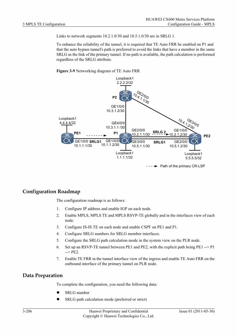
Links to network segments 10.2.1.0/30 and 10.5.1.0/30 are in SRLG 1.
To enhance the reliability of the tunnel, it is required that TE Auto FRR be enabled on P1 andthat the auto bypass tunnel's path is preferred to avoid the links that have a member in the sameSRLG as the link of the primary tunnel. If no path is available, the path calculation is performedregardless of the SRLG attribute.
Figure 3-9 Networking diagram of TE Auto FRR
Loopback12.2.2.2/32
Loopback14.4.4.4/32
Loopback11.1.1.1/32
GE2/0/0
GE1/0/010.3.1.2/30
GE4/0/010.3.1.1 /30
GE1/0/0
GE3/0/0
10.1.1.1/30
10.4.1.1/30
10.4.1.2/30PE1 P1
PE2
P2
Path of the primary CR-LSP
GE3/0/010.5.1.1/30
GE2/0/010.5.1.2/30
Loopback15.5.5.5/32
GE2/0/010.2.1.1/30
SRLG1GE1/0/010.1.1.2/30
SRLG1
SRLG 2 GE1/0/010.2.1.2/30
Configuration RoadmapThe configuration roadmap is as follows:
1. Configure IP address and enable IGP on each node.2. Enable MPLS, MPLS TE and MPLS RSVP-TE globally and in the interfaces view of each
node.3. Configure IS-IS TE on each node and enable CSPF on PE1 and P1.4. Configure SRLG numbers for SRLG member interfaces.5. Configure the SRLG path calculation mode in the system view on the PLR node.6. Set up an RSVP-TE tunnel between PE1 and PE2, with the explicit path being PE1 --> P1
--> PE2.7. Enable TE FRR in the tunnel interface view of the ingress and enable TE Auto FRR on the
outbound interface of the primary tunnel on PLR node.
Data PreparationTo complete the configuration, you need the following data:
l SRLG numberl SRLG path calculation mode (preferred or strict)
3 MPLS TE ConfigurationHUAWEI CX600 Metro Services Platform
Configuration Guide - MPLS
3-206 Huawei Proprietary and ConfidentialCopyright © Huawei Technologies Co., Ltd.
Issue 01 (2011-05-30)
Procedure
Step 1 Configure an IP address for each interface.
As shown in Figure 3-9, configure an IP address for each interface, create loopback interfaceon each node, and then configure the IP address of the loopback interface as the MPLS LSR ID.For configuration details, see the configuration file of this example, and are not provided here.
Step 2 Configure an IGP.
Configure OSPF or IS-IS on each node to ensure that nodes can communicate with each other.The example in this document use IS-IS. For configuration details, see the configuration file ofthis example.
Step 3 Configure basic MPLS functions.
On each node, configure an LSR ID and enable MPLS in the system view. Enable MPLS in theinterface view. For configuration details, see the configuration file of this example.
Step 4 Configure basic MPLS TE functions.
On each node, enable MPLS-TE and MPLS RSVP-TE in the MPLS view and in the interfaceview. Configure the maximum bandwidth and maximum reservable bandwidth for eachinterface. For configuration details, see the configuration file of this example.
Step 5 Configure IS-IS TE and CSPF.
Configure IS-IS TE on each node and CSPF on PE1 and P1. For configuration details, see theconfiguration file of this example.
Step 6 Configure SRLG
# On P1, add links to network segments 10.2.1.0/30 10.5.1.0/30 to SRLG 1.
[P1] interface gigabitethernet 2/0/0[P1-GigabitEthernet2/0/0] mpls te srlg 1[P1-GigabitEthernet2/0/0] quit[P1] interface gigabitethernet 3/0/0[P1-GigabitEthernet3/0/0] mpls te srlg 1[P1-GigabitEthernet3/0/0] quit
# Configure the SRLG path calculation mode on the PLR node.
[P1] mpls[P1-mpls] mpls te srlg path-calculation preferred
# Run the display mpls te srlg command on P1, and you can view information about the SRLGand the interfaces that belong to the SRLG.
[P1] display mpls te srlg allTotal SRLG supported : 512Total SRLG configured : 2
SRLG 1: GE2/0/0 GE3/0/0
# Run the display mpls te link-administration srlg-information command on P1, and you canview information about the SRLG memberships of the interfaces.
[P1] display mpls te link-administration srlg-information
SRLGs on GigabitEthernet2/0/0: 1
HUAWEI CX600 Metro Services PlatformConfiguration Guide - MPLS 3 MPLS TE Configuration
Issue 01 (2011-05-30) Huawei Proprietary and ConfidentialCopyright © Huawei Technologies Co., Ltd.
3-207
SRLGs on GigabitEthernet3/0/0: 1
# Run the display mpls te cspf tedb srlg command on P1, and you can view TEDB informationof the specified SRLG.
[P1] display mpls te cspf tedb srlg 1Interface-Address IGP-Type Area10.2.1.1 ISIS 110.5.1.1 ISIS 110.2.1.1 ISIS 210.5.1.1 ISIS 2
Step 7 Configure the explicit path of the primary tunnel.
# Configure the explicit path of the primary tunnel on PE1.
<PE1> system-view[PE1] explicit-path main[PE1-explicit-path-main] next hop 10.1.1.2[PE1-explicit-path-main] next hop 10.2.1.2[PE1-explicit-path-main] next hop 5.5.5.5[PE1-explicit-path-main] quit
# Display information about the explicit path on PE1.
[PE1] display explicit-path mainPath Name : main Path Status : Enabled 1 10.1.1.2 Strict Include 2 10.2.1.2 Strict Include 3 5.5.5.5 Strict Include
Step 8 Configure the tunnel interfaces for the primary tunnel.
# Create a tunnel interface on PE1, specify an explicit path, and configure the tunnel bandwidth.
[PE1] interface tunnel 1/0/0[PE1-Tunnel1/0/0] ip address unnumbered interface loopback 1[PE1-Tunnel1/0/0] tunnel-protocol mpls te[PE1-Tunnel1/0/0] destination 5.5.5.5[PE1-Tunnel1/0/0] mpls te tunnel-id 100[PE1-Tunnel1/0/0] mpls te path explicit-path main[PE1-Tunnel1/0/0] mpls te bandwidth ct0 10000[PE1-Tunnel1/0/0] mpls te commit
# Run the display interface tunnel 1/0/0 command on PE1, and you can see that the status ofthe tunnel is Up.
[PE1] display interface tunnel 1/0/0Tunnel1/0/0 current state : UPLine protocol current state : UP...
NOTE
Take note of the preceding items that appear in the display interface tunnel 1/0/0 command output.Information in "..." can be ignored.
Step 9 Configure TE Auto FRR.
# Enable TE auto FRR on the GE2/0/0 of P1.
[P1] interface gigabitethernet 2/0/0[P1-GigabitEthernet2/0/0] mpls te auto-frr link[P1-GigabitEthernet2/0/0] quit
# Enable TE FRR in the tunnel interface view of PE1.
3 MPLS TE ConfigurationHUAWEI CX600 Metro Services Platform
Configuration Guide - MPLS
3-208 Huawei Proprietary and ConfidentialCopyright © Huawei Technologies Co., Ltd.
Issue 01 (2011-05-30)
[PE1] interface tunnel 1/0/0[PE1-Tunnel1/0/0] mpls te fast-reroute[PE1-Tunnel1/0/0] mpls te commit
Run the display mpls te tunnel path Tunnel1/0/0 command on PE1, and you can see that thelocal protection is available on the outbound interface (10.2.1.1) of the primary tunnel on P1.
[PE1] display mpls te tunnel path Tunnel1/0/0 Tunnel Interface Name : Tunnel1/0/0 Lsp ID : 5.5.5.5 :1 Hop Information Hop 0 10.1.1.1 Hop 1 10.1.1.2 Label 65536 Hop 2 1.1.1.1 Label 65536 Hop 3 10.2.1.1 Local-Protection available Hop 4 10.2.1.2 Label 3 Hop 5 5.5.5.5 Label 3
Step 10 Verify the configuration.
# Run the display mpls te tunnel name Tunnel1/0/0 verbose command on P1, and you cansee that the primary tunnel is bound with a bypass tunnel, tunnel 0/0/2048. The FRR next hopis 10.4.1.2.
[P1] display mpls te tunnel name Tunnel1/0/0 verbose No : 1 Tunnel-Name : Tunnel1/0/0 TunnelIndex : 1 LSP Index : 3072 Session ID : 100 LSP ID : 1 Lsr Role : Transit LSP Type : Primary Ingress LSR ID : 4.4.4.4 Egress LSR ID : 5.5.5.5 In-Interface : GE1/0/0 Out-Interface : GE2/0/0 Sign-Protocol : RSVP TE Resv Style : SE IncludeAnyAff : 0x0 ExcludeAnyAff : 0x0 IncludeAllAff : 0x0 LspConstraint : -
ER-Hop Table Index : - AR-Hop Table Index: 2 C-Hop Table Index : - PrevTunnelIndexInSession: - NextTunnelIndexInSession: - PSB Handle : 65546 Created Time : 2009/03/30 09:52:03 -------------------------------- DS-TE Information -------------------------------- Bandwidth Reserved Flag : Reserved CT0 Bandwidth(Kbit/sec) : 10000 CT1 Bandwidth(Kbit/sec): 0 CT2 Bandwidth(Kbit/sec) : 0 CT3 Bandwidth(Kbit/sec): 0 CT4 Bandwidth(Kbit/sec) : 0 CT5 Bandwidth(Kbit/sec): 0 CT6 Bandwidth(Kbit/sec) : 0 CT7 Bandwidth(Kbit/sec): 0 Setup-Priority : 7 Hold-Priority : 7 -------------------------------- FRR Information -------------------------------- Primary LSP Info TE Attribute Flag : 0x63 Protected Flag : 0x1 Bypass In Use : Not Used Bypass Tunnel Id : 67141670 BypassTunnel : Tunnel Index[Tunnel0/0/2048], InnerLabel[3] Bypass Lsp ID : - FrrNextHop : 10.4.1.2 ReferAutoBypassHandle : 2049 FrrPrevTunnelTableIndex : - FrrNextTunnelTableIndex: - Bypass Attribute(Not configured) Setup Priority : - Hold Priority : - HopLimit : - Bandwidth : - IncludeAnyGroup : - ExcludeAnyGroup : - IncludeAllGroup : -
HUAWEI CX600 Metro Services PlatformConfiguration Guide - MPLS 3 MPLS TE Configuration
Issue 01 (2011-05-30) Huawei Proprietary and ConfidentialCopyright © Huawei Technologies Co., Ltd.
3-209
Bypass Unbound Bandwidth Info(Kbit/sec) CT0 Unbound Bandwidth : - CT1 Unbound Bandwidth: - CT2 Unbound Bandwidth : - CT3 Unbound Bandwidth: - CT4 Unbound Bandwidth : - CT5 Unbound Bandwidth: - CT6 Unbound Bandwidth : - CT7 Unbound Bandwidth: - -------------------------------- BFD Information -------------------------------- NextSessionTunnelIndex : - PrevSessionTunnelIndex: - NextLspId : - PrevLspId : -
# Run the display mpls te tunnel path Tunnel0/0/2048 command on the P1 to check the pathof the bypass tunnel, you can see that the path of the bypass tunnel is P1-->P2-->PE2.
[P1] display mpls te tunnel path Tunnel0/0/2048 Tunnel Interface Name : Tunnel0/0/2048 Lsp ID : 1.1.1.1 :2049 :1 Hop Information Hop 0 10.3.1.1 Hop 1 10.3.1.2 Hop 2 2.2.2.2 Hop 3 10.4.1.1 Hop 4 10.4.1.2 Hop 5 5.5.5.5
# Run the shutdown command on GE 4/0/0 of P1.
[P1] interface gigabitethernet4/0/0[P1-GigabitEthernet4/0/0] shutdown[P1-GigabitEthernet4/0/0] return
# Run the display interface tunnel 1/0/0 command on PE1, and you can see that the status ofthe primary tunnel is Up.
[PE1] display interface tunnel 1/0/0Tunnel1/0/0 current state : UPLine protocol current state : UP...
NOTE
Take note of the preceding items that appear in the display interface tunnel 1/0/0 command output.Information in "..." can be ignored.
# Run the display mpls te tunnel name Tunnel1/0/0 verbose command on P1, and you cansee that the primary tunnel is still bound with the tunnel 0/0/2048 and the FRR next hop is10.5.1.2.
<P1> display mpls te tunnel name Tunnel1/0/0 verbose No : 1 Tunnel-Name : Tunnel1/0/0 TunnelIndex : 1 LSP Index : 2048 Session ID : 100 LSP ID : 1 Lsr Role : Transit Ingress LSR ID : 4.4.4.4 Egress LSR ID : 5.5.5.5 In-Interface : GE1/0/0 Out-Interface : GE2/0/0 Sign-Protocol : RSVP TE Resv Style : SE IncludeAnyAff : 0x0 ExcludeAnyAff : 0x0 IncludeAllAff : 0x0 ER-Hop Table Index : - AR-Hop Table Index: 5 C-Hop Table Index : - PrevTunnelIndexInSession: - NextTunnelIndexInSession: - PSB Handle : 65547 Created Time : 2009/03/30 09:52:03 -------------------------------- DS-TE Information --------------------------------
3 MPLS TE ConfigurationHUAWEI CX600 Metro Services Platform
Configuration Guide - MPLS
3-210 Huawei Proprietary and ConfidentialCopyright © Huawei Technologies Co., Ltd.
Issue 01 (2011-05-30)
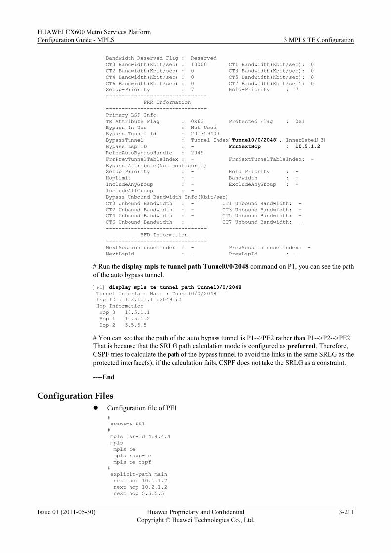
Bandwidth Reserved Flag : Reserved CT0 Bandwidth(Kbit/sec) : 10000 CT1 Bandwidth(Kbit/sec): 0 CT2 Bandwidth(Kbit/sec) : 0 CT3 Bandwidth(Kbit/sec): 0 CT4 Bandwidth(Kbit/sec) : 0 CT5 Bandwidth(Kbit/sec): 0 CT6 Bandwidth(Kbit/sec) : 0 CT7 Bandwidth(Kbit/sec): 0 Setup-Priority : 7 Hold-Priority : 7 -------------------------------- FRR Information -------------------------------- Primary LSP Info TE Attribute Flag : 0x63 Protected Flag : 0x1 Bypass In Use : Not Used Bypass Tunnel Id : 201359400 BypassTunnel : Tunnel Index[Tunnel0/0/2048], InnerLabel[3] Bypass Lsp ID : - FrrNextHop : 10.5.1.2 ReferAutoBypassHandle : 2049 FrrPrevTunnelTableIndex : - FrrNextTunnelTableIndex: - Bypass Attribute(Not configured) Setup Priority : - Hold Priority : - HopLimit : - Bandwidth : - IncludeAnyGroup : - ExcludeAnyGroup : - IncludeAllGroup : - Bypass Unbound Bandwidth Info(Kbit/sec) CT0 Unbound Bandwidth : - CT1 Unbound Bandwidth: - CT2 Unbound Bandwidth : - CT3 Unbound Bandwidth: - CT4 Unbound Bandwidth : - CT5 Unbound Bandwidth: - CT6 Unbound Bandwidth : - CT7 Unbound Bandwidth: - -------------------------------- BFD Information -------------------------------- NextSessionTunnelIndex : - PrevSessionTunnelIndex: - NextLspId : - PrevLspId : -
# Run the display mpls te tunnel path Tunnel0/0/2048 command on P1, you can see the pathof the auto bypass tunnel.
[P1] display mpls te tunnel path Tunnel0/0/2048 Tunnel Interface Name : Tunnel0/0/2048 Lsp ID : 123.1.1.1 :2049 :2 Hop Information Hop 0 10.5.1.1 Hop 1 10.5.1.2 Hop 2 5.5.5.5
# You can see that the path of the auto bypass tunnel is P1-->PE2 rather than P1-->P2-->PE2.That is because that the SRLG path calculation mode is configured as preferred. Therefore,CSPF tries to calculate the path of the bypass tunnel to avoid the links in the same SRLG as theprotected interface(s); if the calculation fails, CSPF does not take the SRLG as a constraint.
----End
Configuration Filesl Configuration file of PE1
# sysname PE1# mpls lsr-id 4.4.4.4 mpls mpls te mpls rsvp-te mpls te cspf# explicit-path main next hop 10.1.1.2 next hop 10.2.1.2 next hop 5.5.5.5
HUAWEI CX600 Metro Services PlatformConfiguration Guide - MPLS 3 MPLS TE Configuration
Issue 01 (2011-05-30) Huawei Proprietary and ConfidentialCopyright © Huawei Technologies Co., Ltd.
3-211
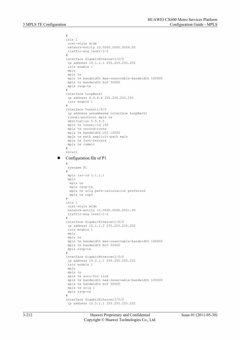
#isis 1 cost-style wide network-entity 10.0000.0000.0004.00 traffic-eng level-1-2#interface GigabitEthernet1/0/0 ip address 10.1.1.1 255.255.255.252 isis enable 1 mpls mpls te mpls te bandwidth max-reservable-bandwidth 100000 mpls te bandwidth bc0 50000 mpls rsvp-te#interface LoopBack1 ip address 4.4.4.4 255.255.255.255 isis enable 1#interface Tunnel1/0/0 ip address unnumbered interface LoopBack1 tunnel-protocol mpls te destination 5.5.5.5 mpls te tunnel-id 100 mpls te record-route mpls te bandwidth ct0 10000 mpls te path explicit-path main mpls te fast-reroute mpls te commit#return
l Configuration file of P1# sysname P1# mpls lsr-id 1.1.1.1 mpls mpls te mpls rsvp-te mpls te srlg path-calculation preferred mpls te cspf#isis 1 cost-style wide network-entity 10.0000.0000.0001.00 traffic-eng level-1-2#interface GigabitEthernet1/0/0 ip address 10.1.1.2 255.255.255.252 isis enable 1 mpls mpls te mpls te bandwidth max-reservable-bandwidth 100000 mpls te bandwidth bc0 50000 mpls rsvp-te#interface GigabitEthernet2/0/0 ip address 10.2.1.1 255.255.255.252 isis enable 1 mpls mpls te mpls te auto-frr link mpls te bandwidth max-reservable-bandwidth 100000 mpls te bandwidth bc0 50000 mpls te srlg 1 mpls rsvp-te#interface GigabitEthernet3/0/0 ip address 10.5.1.1 255.255.255.252
3 MPLS TE ConfigurationHUAWEI CX600 Metro Services Platform
Configuration Guide - MPLS
3-212 Huawei Proprietary and ConfidentialCopyright © Huawei Technologies Co., Ltd.
Issue 01 (2011-05-30)
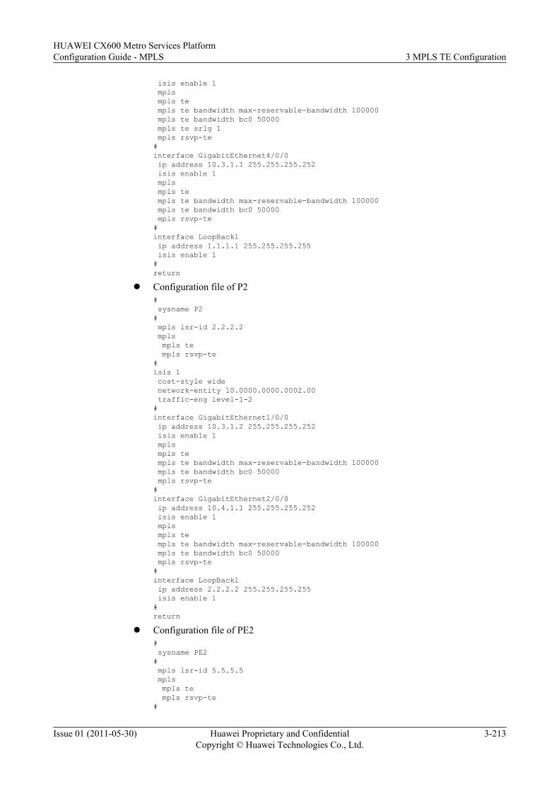
isis enable 1 mpls mpls te mpls te bandwidth max-reservable-bandwidth 100000 mpls te bandwidth bc0 50000 mpls te srlg 1 mpls rsvp-te#interface GigabitEthernet4/0/0 ip address 10.3.1.1 255.255.255.252 isis enable 1 mpls mpls te mpls te bandwidth max-reservable-bandwidth 100000 mpls te bandwidth bc0 50000 mpls rsvp-te#interface LoopBack1 ip address 1.1.1.1 255.255.255.255 isis enable 1#return
l Configuration file of P2# sysname P2# mpls lsr-id 2.2.2.2 mpls mpls te mpls rsvp-te#isis 1 cost-style wide network-entity 10.0000.0000.0002.00 traffic-eng level-1-2#interface GigabitEthernet1/0/0 ip address 10.3.1.2 255.255.255.252 isis enable 1 mpls mpls te mpls te bandwidth max-reservable-bandwidth 100000 mpls te bandwidth bc0 50000 mpls rsvp-te#interface GigabitEthernet2/0/0 ip address 10.4.1.1 255.255.255.252 isis enable 1 mpls mpls te mpls te bandwidth max-reservable-bandwidth 100000 mpls te bandwidth bc0 50000 mpls rsvp-te#interface LoopBack1 ip address 2.2.2.2 255.255.255.255 isis enable 1#return
l Configuration file of PE2# sysname PE2# mpls lsr-id 5.5.5.5 mpls mpls te mpls rsvp-te#
HUAWEI CX600 Metro Services PlatformConfiguration Guide - MPLS 3 MPLS TE Configuration
Issue 01 (2011-05-30) Huawei Proprietary and ConfidentialCopyright © Huawei Technologies Co., Ltd.
3-213
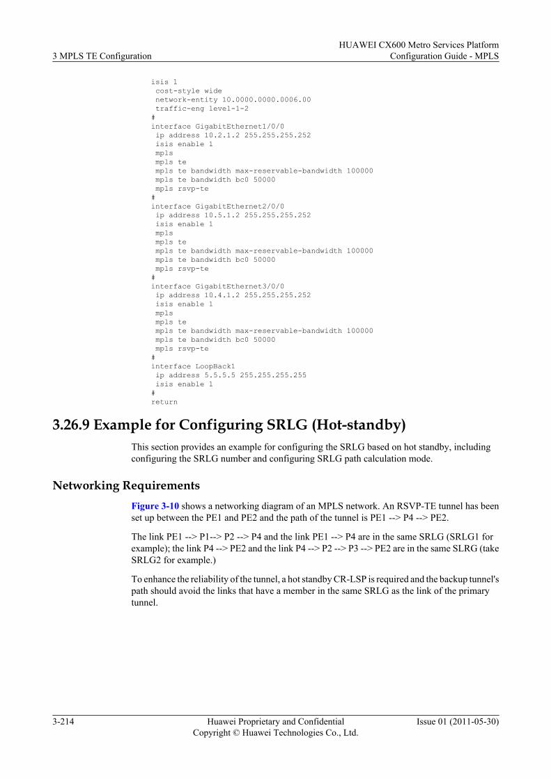
isis 1 cost-style wide network-entity 10.0000.0000.0006.00 traffic-eng level-1-2#interface GigabitEthernet1/0/0 ip address 10.2.1.2 255.255.255.252 isis enable 1 mpls mpls te mpls te bandwidth max-reservable-bandwidth 100000 mpls te bandwidth bc0 50000 mpls rsvp-te#interface GigabitEthernet2/0/0 ip address 10.5.1.2 255.255.255.252 isis enable 1 mpls mpls te mpls te bandwidth max-reservable-bandwidth 100000 mpls te bandwidth bc0 50000 mpls rsvp-te#interface GigabitEthernet3/0/0 ip address 10.4.1.2 255.255.255.252 isis enable 1 mpls mpls te mpls te bandwidth max-reservable-bandwidth 100000 mpls te bandwidth bc0 50000 mpls rsvp-te#interface LoopBack1 ip address 5.5.5.5 255.255.255.255 isis enable 1#return
3.26.9 Example for Configuring SRLG (Hot-standby)This section provides an example for configuring the SRLG based on hot standby, includingconfiguring the SRLG number and configuring SRLG path calculation mode.
Networking RequirementsFigure 3-10 shows a networking diagram of an MPLS network. An RSVP-TE tunnel has beenset up between the PE1 and PE2 and the path of the tunnel is PE1 --> P4 --> PE2.
The link PE1 --> P1--> P2 --> P4 and the link PE1 --> P4 are in the same SRLG (SRLG1 forexample); the link P4 --> PE2 and the link P4 --> P2 --> P3 --> PE2 are in the same SLRG (takeSRLG2 for example.)
To enhance the reliability of the tunnel, a hot standby CR-LSP is required and the backup tunnel'spath should avoid the links that have a member in the same SRLG as the link of the primarytunnel.
3 MPLS TE ConfigurationHUAWEI CX600 Metro Services Platform
Configuration Guide - MPLS
3-214 Huawei Proprietary and ConfidentialCopyright © Huawei Technologies Co., Ltd.
Issue 01 (2011-05-30)
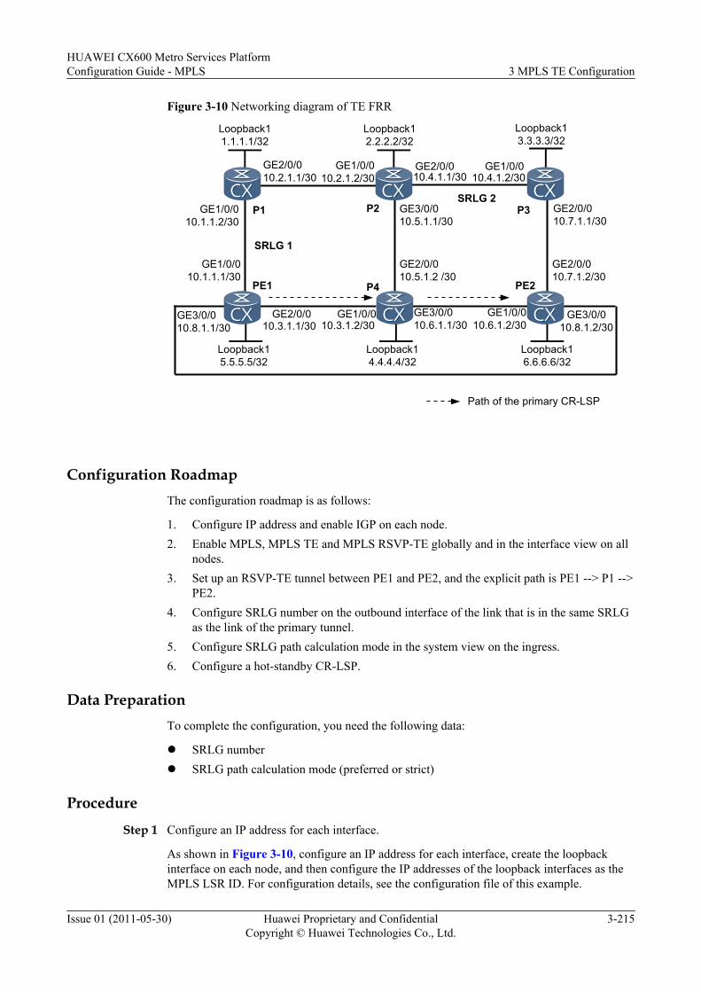
Figure 3-10 Networking diagram of TE FRR
Loopback11.1.1.1/32
Loopback12.2.2.2/32
Loopback15.5.5.5/32
Loopback14.4.4.4/32
GE1/0/010.1.1.1/30
GE1/0/010.1.1.2/30
GE2/0/010.2.1.1/30
GE1/0/010.2.1.2/30
GE2/0/0
GE3/0/010.5.1.1/30
GE2/0/010.5.1.2 /30
GE1/0/0GE2/0/0
GE1/0/0
10.3.1.2/3010.3.1.1/30
10.4.1.1/30 10.4.1.2/30
PE1 P4 PE2
P2
Path of the primary CR-LSP
SRLG 1
P3 GE2/0/010.7.1.1/30
GE3/0/010.6.1.1/30
GE2/0/010.7.1.2/30
GE1/0/010.6.1.2/30
P1
Loopback16.6.6.6/32
GE3/0/010.8.1.1/30
GE3/0/010.8.1.2/30
Loopback13.3.3.3/32
SRLG 2
Configuration RoadmapThe configuration roadmap is as follows:
1. Configure IP address and enable IGP on each node.2. Enable MPLS, MPLS TE and MPLS RSVP-TE globally and in the interface view on all
nodes.3. Set up an RSVP-TE tunnel between PE1 and PE2, and the explicit path is PE1 --> P1 -->
PE2.4. Configure SRLG number on the outbound interface of the link that is in the same SRLG
as the link of the primary tunnel.5. Configure SRLG path calculation mode in the system view on the ingress.6. Configure a hot-standby CR-LSP.
Data PreparationTo complete the configuration, you need the following data:
l SRLG numberl SRLG path calculation mode (preferred or strict)
ProcedureStep 1 Configure an IP address for each interface.
As shown in Figure 3-10, configure an IP address for each interface, create the loopbackinterface on each node, and then configure the IP addresses of the loopback interfaces as theMPLS LSR ID. For configuration details, see the configuration file of this example.
HUAWEI CX600 Metro Services PlatformConfiguration Guide - MPLS 3 MPLS TE Configuration
Issue 01 (2011-05-30) Huawei Proprietary and ConfidentialCopyright © Huawei Technologies Co., Ltd.
3-215
The detailed configuration is not provided here.
Step 2 Configure IGP.
Configure OSPF or IS-IS on each node to ensure that nodes can communicate with each other.The example in this document use IS-IS. For configuration details, see the configuration file ofthis example.
Step 3 Configure basic MPLS functions.
On each node, configure an LSR ID and enable MPLS in the system view. Enable MPLS in theinterface view. For configuration details, see the configuration file of this example.
Step 4 Configure basic MPLS TE functions and enable MPLS RSVP-TE.
On each node, enable MPLS-TE and MPLS RSVP-TE in the system view and in the interfaceview. Configure the maximum bandwidth and maximum reservable bandwidth for eachinterface. For configuration details, see the configuration file of this example.
Step 5 Configure IS-IS TE and CSPF.
Configure IS-IS TE on each node and CSPF on PE1. For configuration details, see theconfiguration file of this example.
Step 6 Configure the explicit path of the primary CR-LSP.
# Configure the explicit path of the primary CR-LSP on PE1.
<PE1> system-view[PE1] explicit-path main[PE1-explicit-path-main] next hop 10.3.1.2[PE1-explicit-path-main] next hop 10.6.1.2[PE1-explicit-path-main] next hop 6.6.6.6[PE1-explicit-path-main] quit
# Display information about the explicit path on PE1.
[PE1] display explicit-path mainPath Name : main Path Status : Enabled 1 10.1.1.2 Strict Include 2 10.2.1.2 Strict Include 3 5.5.5.5 Strict Include
Step 7 Configure the tunnel interfaces for the primary tunnel.
# Create a tunnel interface on PE1, specify an explicit path, and configure the tunnel bandwidth.
[PE1] interface tunnel 1/0/0[PE1-Tunnel1/0/0] ip address unnumbered interface loopback 1[PE1-Tunnel1/0/0] tunnel-protocol mpls te[PE1-Tunnel1/0/0] destination 6.6.6.6[PE1-Tunnel1/0/0] mpls te tunnel-id 100[PE1-Tunnel1/0/0] mpls te path explicit-path main[PE1-Tunnel1/0/0] mpls te bandwidth ct0 10000[PE1-Tunnel1/0/0] mpls te commit
Run the display interface tunnel 1/0/0 command on PE1, and you can see that the status of thetunnel is Up.
[PE1] display interface tunnel 1/0/0Tunnel1/0/0 current state : UPLine protocol current state : UP...
3 MPLS TE ConfigurationHUAWEI CX600 Metro Services Platform
Configuration Guide - MPLS
3-216 Huawei Proprietary and ConfidentialCopyright © Huawei Technologies Co., Ltd.
Issue 01 (2011-05-30)
Take note of the preceding items that appear in the display interface tunnel 1/0/0 commandoutput. Information in "..." can be ignored.
Step 8 Configure SRLG
# Configure SRLG1 for the link PE1 --> P1 and the link PE1 --> P4.
[PE1] interface gigabitethernet 1/0/0[PE1-GigabitEthernet1/0/0] mpls te srlg 1[PE1-GigabitEthernet1/0/0] quit[PE1] interface gigabitethernet 2/0/0[PE1-GigabitEthernet2/0/0] mpls te srlg 1[PE1-GigabitEthernet2/0/0] mpls te srlg 2
# Configure SRLG 2 for the link P2 --> P3.
[P2] interface gigabitethernet 2/0/0[P2-GigabitEthernet2/0/0] mpls te srlg 2[P2-GigabitEthernet2/0/0] quit
# Configure the SRLG path calculation mode on the ingress.
[PE1] mpls[PE1-mpls] mpls te srlg path-calculation strict[PE1-mpls] quit
Run the display mpls te srlg command, and you can view information about the SRLG and theinterfaces that belong to that SRLG.
[P1] display mpls te srlg allTotal SRLG supported : 512Total SRLG configured : 2
SRLG 1: GE1/0/0 GE2/0/0
SRLG 2: GE2/0/0
Run the display mpls te link-administration srlg-information command, and you can viewinformation about the memberships on the interface.
[PE1] display mpls te link-administration srlg-information
SRLGs on GigabitEthernet1/0/0: 1
SRLGs on GigabitEthernet2/0/0: 1 2
Run the display mpls te cspf tedb srlg command, and you can view TEDB information of thespecified SRLG.
Take the display on PE1 as an example.
[PE1] display mpls te cspf tedb srlg 1Interface-Address IGP-Type Area10.1.1.1 ISIS 110.1.1.1 ISIS 210.3.1.1 ISIS 110.3.1.1 ISIS 2[PE1] display mpls te cspf tedb srlg 2Interface-Address IGP-Type Area10.3.1.1 ISIS 110.3.1.1 ISIS 210.4.1.1 ISIS 110.4.1.1 ISIS 2
Step 9 Configure a hot-standby CR-LSP on the ingress.
# Configure PE1.
HUAWEI CX600 Metro Services PlatformConfiguration Guide - MPLS 3 MPLS TE Configuration
Issue 01 (2011-05-30) Huawei Proprietary and ConfidentialCopyright © Huawei Technologies Co., Ltd.
3-217
[PE1] interface tunnel 1/0/0[PE1-Tunnel1/0/0] mpls te backup hot-standby[PE1-Tunnel1/0/0] mpls te commit
Run the display mpls te hot-standby state interface tunnel 1/0/0 command on PE1, and youcan view information about the hot standby.
[PE1] display mpls te hot-standby state interface tunnel 1/0/0----------------------------------------------------------------Verbose information about the Tunnel1/0/0 hot-standby state----------------------------------------------------------------
session id : 100main LSP token : 0x100201ahot-standby LSP token : 0x100201bHSB switch result : Primary LSPWTR : 10susing same path : --
Step 10 Verify the configuration.
# Run the shutdown command on GE 3/0/0 of PE1.
[PE1] interface gigabitethernet3/0/0[PE1-GigabitEthernet3/0/0] shutdown[PE1-GigabitEthernet3/0/0] quit
# Run the display mpls te hot-standby state interface tunnel 1/0/0 command on PE1 again,and you can see that the hot-standby LSP token is 0x0. This means that the hot-standby LSP isnot set up even though there are paths for setting up the hot-standby LSP.
[PE1] display mpls te hot-standby state interface tunnel 1/0/0----------------------------------------------------------------Verbose information about the Tunnel1/0/0 hot-standby state----------------------------------------------------------------
session id : 100main LSP token : 0x100201chot-standby LSP token : 0x0HSB switch result : Primary LSPWTR : 10susing same path : --
----End
Configuration Filesl Configuration file of PE1
# sysname PE1# mpls lsr-id 5.5.5.5 mpls mpls te mpls rsvp-te mpls te srlg path-calculation strict mpls te cspf# explicit-path main next hop 10.3.1.2 next hop 10.6.1.2 next hop 6.6.6.6#isis 1 cost-style wide network-entity 10.0000.0000.0005.00 traffic-eng level-1-2
3 MPLS TE ConfigurationHUAWEI CX600 Metro Services Platform
Configuration Guide - MPLS
3-218 Huawei Proprietary and ConfidentialCopyright © Huawei Technologies Co., Ltd.
Issue 01 (2011-05-30)
#interface GigabitEthernet1/0/0 ip address 10.1.1.1 255.255.255.252 isis enable 1 mpls mpls te mpls te bandwidth max-reservable-bandwidth 100000 mpls te bandwidth bc0 50000 mpls te srlg 1 mpls rsvp-te#interface GigabitEthernet2/0/0 ip address 10.2.1.1 255.255.255.252 isis enable 1 mpls mpls te mpls te bandwidth max-reservable-bandwidth 100000 mpls te bandwidth bc0 50000 mpls te srlg 1 mpls te srlg 2 mpls rsvp-te#interface GigabitEthernet3/0/0 ip address 10.8.1.1 255.255.255.252 isis enable 1 mpls mpls te mpls te bandwidth max-reservable-bandwidth 100000 mpls te bandwidth bc0 50000 mpls rsvp-te#interface LoopBack1 ip address 5.5.5.5 255.255.255.255 isis enable 1#interface Tunnel1/0/0 ip address unnumbered interface LoopBack1 tunnel-protocol mpls te destination 6.6.6.6 mpls te tunnel-id 100 mpls te record-route mpls te bandwidth ct0 10000 mpls te path explicit-path main mpls te backup hot-standby mpls te commit#return
l Configuration file of P1# sysname P1# mpls lsr-id 1.1.1.1 mpls mpls te mpls rsvp-te#isis 1 cost-style wide network-entity 10.0000.0000.0001.00 traffic-eng level-1-2#interface GigabitEthernet1/0/0 ip address 10.1.1.2 255.255.255.252 isis enable 1 mpls mpls te mpls te bandwidth max-reservable-bandwidth 100000 mpls te bandwidth bc0 50000 mpls rsvp-te
HUAWEI CX600 Metro Services PlatformConfiguration Guide - MPLS 3 MPLS TE Configuration
Issue 01 (2011-05-30) Huawei Proprietary and ConfidentialCopyright © Huawei Technologies Co., Ltd.
3-219
#interface GigabitEthernet2/0/0 ip address 10.2.1.1 255.255.255.252 isis enable 1 mpls mpls te mpls te bandwidth max-reservable-bandwidth 100000 mpls te bandwidth bc0 50000 mpls rsvp-te#interface LoopBack1 ip address 1.1.1.1 255.255.255.255 isis enable 1#return?
l Configuration file of P2# sysname P2# mpls lsr-id 2.2.2.2 mpls mpls te mpls rsvp-te#isis 1 cost-style wide network-entity 10.0000.0000.0002.00 traffic-eng level-1-2#interface GigabitEthernet1/0/0 ip address 10.2.1.2 255.255.255.252 isis enable 1 mpls mpls te mpls te bandwidth max-reservable-bandwidth 100000 mpls te bandwidth bc0 50000 mpls rsvp-te#interface GigabitEthernet2/0/0 ip address 10.4.1.1 255.255.255.252 isis enable 1 mpls mpls te mpls te bandwidth max-reservable-bandwidth 100000 mpls te bandwidth bc0 50000 mpls te srlg 2 mpls rsvp-te#interface GigabitEthernet3/0/0 ip address 10.5.1.1 255.255.255.252 isis enable 1 mpls mpls te mpls te bandwidth max-reservable-bandwidth 100000 mpls te bandwidth bc0 50000 mpls rsvp-te#interface LoopBack1 ip address 2.2.2.2 255.255.255.255 isis enable 1#return
l Configuration file of P3# sysname P3# mpls lsr-id 3.3.3.3 mpls
3 MPLS TE ConfigurationHUAWEI CX600 Metro Services Platform
Configuration Guide - MPLS
3-220 Huawei Proprietary and ConfidentialCopyright © Huawei Technologies Co., Ltd.
Issue 01 (2011-05-30)
mpls te mpls rsvp-te#isis 1 cost-style wide network-entity 10.0000.0000.0003.00 traffic-eng level-1-2#interface GigabitEthernet1/0/0 ip address 10.4.1.2 255.255.255.252 isis enable 1 mpls mpls te mpls te bandwidth max-reservable-bandwidth 100000 mpls te bandwidth bc0 50000 mpls rsvp-te#interface GigabitEthernet2/0/0 ip address 10.7.1.1 255.255.255.252 isis enable 1 mpls mpls te mpls te bandwidth max-reservable-bandwidth 100000 mpls te bandwidth bc0 50000 mpls rsvp-te#interface LoopBack1 ip address 3.3.3.3 255.255.255.255 isis enable 1#return
l Configuration file of P4# sysname P4# mpls lsr-id 4.4.4.4 mpls mpls te mpls rsvp-te#isis 1 cost-style wide network-entity 10.0000.0000.0004.00 traffic-eng level-1-2#interface GigabitEthernet1/0/0 ip address 10.3.1.2 255.255.255.252 isis enable 1 mpls mpls te mpls te bandwidth max-reservable-bandwidth 100000 mpls te bandwidth bc0 50000 mpls rsvp-te#interface GigabitEthernet2/0/0 ip address 10.5.1.2 255.255.255.252 isis enable 1 mpls mpls te mpls te bandwidth max-reservable-bandwidth 100000 mpls te bandwidth bc0 50000 mpls rsvp-te#interface GigabitEthernet3/0/0 ip address 10.6.1.1 255.255.255.252 isis enable 1 mpls mpls te mpls te bandwidth max-reservable-bandwidth 100000
HUAWEI CX600 Metro Services PlatformConfiguration Guide - MPLS 3 MPLS TE Configuration
Issue 01 (2011-05-30) Huawei Proprietary and ConfidentialCopyright © Huawei Technologies Co., Ltd.
3-221
mpls te bandwidth bc0 50000 mpls rsvp-te#interface LoopBack1 ip address 4.4.4.4 255.255.255.255 isis enable 1#return
l Configuration file of PE2# sysname PE2# mpls lsr-id 6.6.6.6 mpls mpls te mpls rsvp-te#isis 1 cost-style wide network-entity 10.0000.0000.0006.00 traffic-eng level-1-2#interface GigabitEthernet1/0/0 ip address 10.6.1.2 255.255.255.252 isis enable 1 mpls mpls te mpls te bandwidth max-reservable-bandwidth 100000 mpls te bandwidth bc0 50000 mpls rsvp-te#interface GigabitEthernet2/0/0 ip address 10.7.1.2 255.255.255.252 isis enable 1 mpls mpls te mpls te bandwidth max-reservable-bandwidth 100000 mpls te bandwidth bc0 50000 mpls rsvp-te#interface GigabitEthernet3/0/0 ip address 10.8.1.2 255.255.255.252 isis enable 1 mpls mpls te mpls te bandwidth max-reservable-bandwidth 100000 mpls te bandwidth bc0 50000 mpls rsvp-te#interface LoopBack1 ip address 6.6.6.6 255.255.255.255 isis enable 1#Return
3.26.10 Example for Configuring the Limit Rate for TE TunnelTraffic
Networking RequirementsAs shown in Figure 3-11, IS-IS is run on LSR A, LSR B, LSR C, and LSR D. An RSVP-TEtunnel is established from LSR A to LSR D and the BC0 bandwidth of the TE tunnel is 20 Mbit/s. The maximum reservable bandwidth of the link along the tunnel is 100 Mbit/s and thebandwidth constraints model is RDM, and BC0 bandwidth is 100 Mbit/s.
3 MPLS TE ConfigurationHUAWEI CX600 Metro Services Platform
Configuration Guide - MPLS
3-222 Huawei Proprietary and ConfidentialCopyright © Huawei Technologies Co., Ltd.
Issue 01 (2011-05-30)
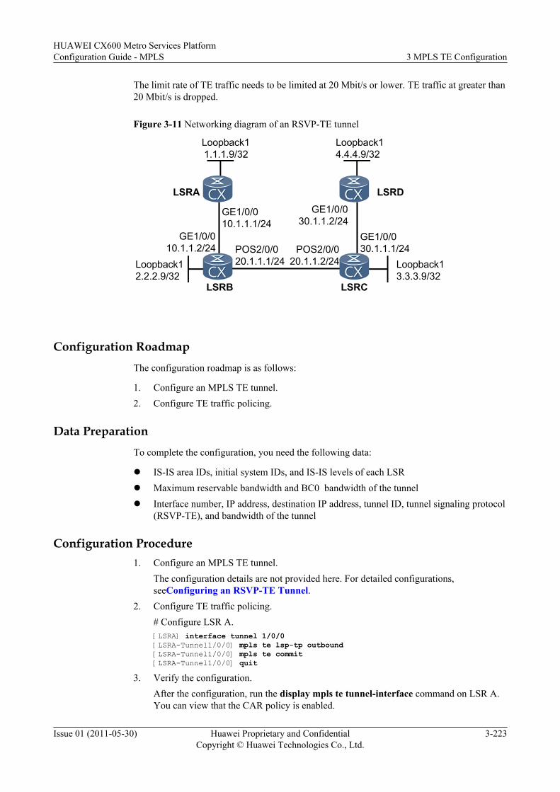
The limit rate of TE traffic needs to be limited at 20 Mbit/s or lower. TE traffic at greater than20 Mbit/s is dropped.
Figure 3-11 Networking diagram of an RSVP-TE tunnel
Loopback14.4.4.9/32
Loopback13.3.3.9/32
Loopback12.2.2.9/32
LSRD
LSRC
POS2/0/020.1.1.1/24
POS2/0/020.1.1.2/24
GE1/0/030.1.1.1/24
GE1/0/030.1.1.2/24
LSRA
LSRB
GE1/0/010.1.1.1/24
GE1/0/010.1.1.2/24
Loopback11.1.1.9/32
Configuration RoadmapThe configuration roadmap is as follows:
1. Configure an MPLS TE tunnel.2. Configure TE traffic policing.
Data PreparationTo complete the configuration, you need the following data:
l IS-IS area IDs, initial system IDs, and IS-IS levels of each LSRl Maximum reservable bandwidth and BC0 bandwidth of the tunnell Interface number, IP address, destination IP address, tunnel ID, tunnel signaling protocol
(RSVP-TE), and bandwidth of the tunnel
Configuration Procedure1. Configure an MPLS TE tunnel.
The configuration details are not provided here. For detailed configurations,seeConfiguring an RSVP-TE Tunnel.
2. Configure TE traffic policing.# Configure LSR A.[LSRA] interface tunnel 1/0/0[LSRA-Tunnel1/0/0] mpls te lsp-tp outbound[LSRA-Tunnel1/0/0] mpls te commit[LSRA-Tunnel1/0/0] quit
3. Verify the configuration.After the configuration, run the display mpls te tunnel-interface command on LSR A.You can view that the CAR policy is enabled.
HUAWEI CX600 Metro Services PlatformConfiguration Guide - MPLS 3 MPLS TE Configuration
Issue 01 (2011-05-30) Huawei Proprietary and ConfidentialCopyright © Huawei Technologies Co., Ltd.
3-223
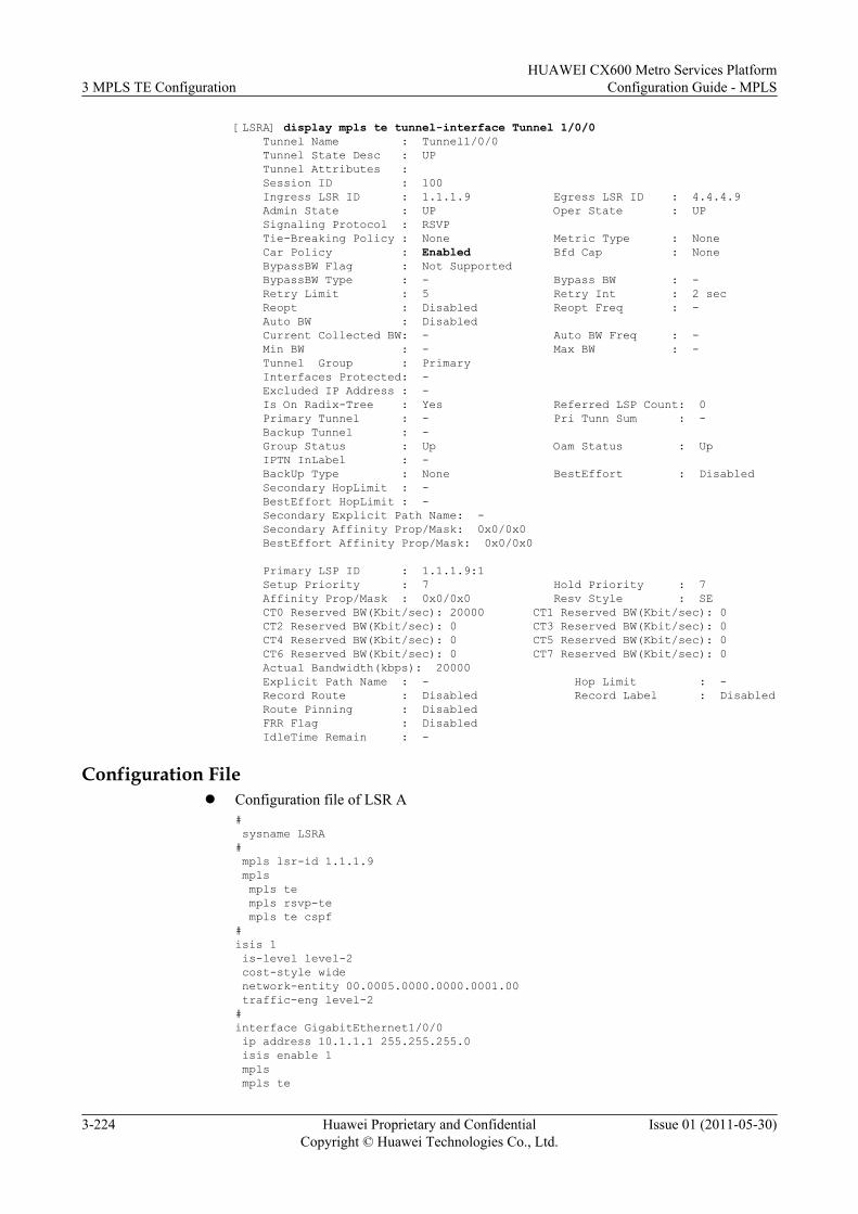
[LSRA] display mpls te tunnel-interface Tunnel 1/0/0 Tunnel Name : Tunnel1/0/0 Tunnel State Desc : UP Tunnel Attributes : Session ID : 100 Ingress LSR ID : 1.1.1.9 Egress LSR ID : 4.4.4.9 Admin State : UP Oper State : UP Signaling Protocol : RSVP Tie-Breaking Policy : None Metric Type : None Car Policy : Enabled Bfd Cap : None BypassBW Flag : Not Supported BypassBW Type : - Bypass BW : - Retry Limit : 5 Retry Int : 2 sec Reopt : Disabled Reopt Freq : - Auto BW : Disabled Current Collected BW: - Auto BW Freq : - Min BW : - Max BW : - Tunnel Group : Primary Interfaces Protected: - Excluded IP Address : - Is On Radix-Tree : Yes Referred LSP Count: 0 Primary Tunnel : - Pri Tunn Sum : - Backup Tunnel : - Group Status : Up Oam Status : Up IPTN InLabel : - BackUp Type : None BestEffort : Disabled Secondary HopLimit : - BestEffort HopLimit : - Secondary Explicit Path Name: - Secondary Affinity Prop/Mask: 0x0/0x0 BestEffort Affinity Prop/Mask: 0x0/0x0
Primary LSP ID : 1.1.1.9:1 Setup Priority : 7 Hold Priority : 7 Affinity Prop/Mask : 0x0/0x0 Resv Style : SE CT0 Reserved BW(Kbit/sec): 20000 CT1 Reserved BW(Kbit/sec): 0 CT2 Reserved BW(Kbit/sec): 0 CT3 Reserved BW(Kbit/sec): 0 CT4 Reserved BW(Kbit/sec): 0 CT5 Reserved BW(Kbit/sec): 0 CT6 Reserved BW(Kbit/sec): 0 CT7 Reserved BW(Kbit/sec): 0 Actual Bandwidth(kbps): 20000 Explicit Path Name : - Hop Limit : - Record Route : Disabled Record Label : Disabled Route Pinning : Disabled FRR Flag : Disabled IdleTime Remain : -
Configuration Filel Configuration file of LSR A
# sysname LSRA# mpls lsr-id 1.1.1.9 mpls mpls te mpls rsvp-te mpls te cspf#isis 1 is-level level-2 cost-style wide network-entity 00.0005.0000.0000.0001.00 traffic-eng level-2#interface GigabitEthernet1/0/0 ip address 10.1.1.1 255.255.255.0 isis enable 1 mpls mpls te
3 MPLS TE ConfigurationHUAWEI CX600 Metro Services Platform
Configuration Guide - MPLS
3-224 Huawei Proprietary and ConfidentialCopyright © Huawei Technologies Co., Ltd.
Issue 01 (2011-05-30)
mpls te bandwidth max-reservable-bandwidth 100000 mpls te bandwidth bc0 100000 mpls rsvp-te#interface LoopBack1 ip address 1.1.1.9 255.255.255.255 isis enable 1#interface Tunnel1/0/0 ip address unnumbered interface LoopBack1 tunnel-protocol mpls te destination 4.4.4.9 mpls te tunnel-id 100 mpls te bandwidth ct0 20000 mpls te lsp-tp outbound mpls te commit#return
l Configuration file of LSR B# sysname LSRB# mpls lsr-id 2.2.2.9 mpls mpls te mpls rsvp-te#isis 1 is-level level-2 cost-style wide network-entity 00.0005.0000.0000.0002.00 traffic-eng level-2#interface GigabitEthernet1/0/0 ip address 10.1.1.2 255.255.255.0 isis enable 1 mpls mpls te mpls rsvp-te#interface Pos2/0/0 link-protocol ppp clock master ip address 20.1.1.1 255.255.255.0 isis enable 1 mpls mpls te mpls te bandwidth max-reservable-bandwidth 100000 mpls te bandwidth bc0 100000 mpls rsvp-te#interface LoopBack1 ip address 2.2.2.9 255.255.255.255 isis enable 1#return
l Configuration file of LSR C# sysname LSRC# mpls lsr-id 3.3.3.9 mpls mpls te mpls rsvp-te#isis 1 is-level level-2 cost-style wide
HUAWEI CX600 Metro Services PlatformConfiguration Guide - MPLS 3 MPLS TE Configuration
Issue 01 (2011-05-30) Huawei Proprietary and ConfidentialCopyright © Huawei Technologies Co., Ltd.
3-225
network-entity 00.0005.0000.0000.0003.00 traffic-eng level-2#interface GigabitEthernet1/0/0 ip address 30.1.1.1 255.255.255.0 isis enable 1 mpls mpls te mpls te bandwidth max-reservable-bandwidth 100000 mpls te bandwidth bc0 100000 mpls rsvp-te#interface Pos2/0/0 link-protocol ppp ip address 20.1.1.2 255.255.255.0 isis enable 1 mpls mpls te mpls rsvp-te#interface LoopBack1 ip address 3.3.3.9 255.255.255.255 isis enable 1#return
l Configuration file of LSR D# sysname LSRD# mpls lsr-id 4.4.4.9 mpls mpls te mpls rsvp-te#isis 1 is-level level-2 cost-style wide network-entity 00.0005.0000.0000.0004.00 traffic-eng level-2#interface GigabitEthernet1/0/0 ip address 30.1.1.2 255.255.255.0 isis enable 1 mpls mpls te mpls rsvp-te#interface LoopBack1 ip address 4.4.4.9 255.255.255.255 isis enable 1#return
3.26.11 Example for Configuring a DS-TE Tunnel in Non-IETFMode (MAM)
This section provides an example for configuring a DS-TE tunnel in non-IETF mode, includingconfiguring the DS-TE mode, bandwidth constraint module, and mapping of CTs and servicetypes.
Networking RequirementsAs shown in Figure 3-12, PEs and P on the MPLS backbone network are enabled with OSPFto interwork with each other. PE1 accesses VPN-A and PE2 accesses VPN-B. VPN-A transmits
3 MPLS TE ConfigurationHUAWEI CX600 Metro Services Platform
Configuration Guide - MPLS
3-226 Huawei Proprietary and ConfidentialCopyright © Huawei Technologies Co., Ltd.
Issue 01 (2011-05-30)
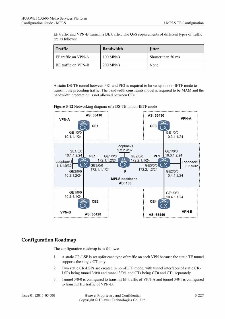
EF traffic and VPN-B transmits BE traffic. The QoS requirements of different types of trafficare as follows:
Traffic Bandwidth Jitter
EF traffic on VPN-A 100 Mbit/s Shorter than 50 ms
BE traffic on VPN-B 200 Mbit/s None
A static DS-TE tunnel between PE1 and PE2 is required to be set up in non-IETF mode totransmit the preceding traffic. The bandwidth constraints model is required to be MAM and thebandwidth preemption is not allowed between CTs.
Figure 3-12 Networking diagram of a DS-TE in non-IETF mode
AS: 65440VPN-B
CE4
PE1
P
AS: 65430VPN-A
CE3
GE1/0/010.3.1.1/24
GE1/0/010.3.1.2/24
AS: 65420VPN-B
CE2
AS: 65410VPN-A
CE1
GE1/0/010.1.1.1/24
GE1/0/010.1.1.2/24
GE3/0/0172.1.1.1/24
GE2/0/0172.2.1.1/24
AS: 100
PE2Loopback11.1.1.9/32
Loopback13.3.3.9/32
GE1/0/010.4.1.1/24
GE1/0/010.2.1.1/24
GE2/0/010.4.1.2/24
GE2/0/010.2.1.2/24
GE1/0/0172.1.1.2/24
GE3/0/0172.2.1.2/24
MPLS backbone
Loopback12.2.2.9/32
Configuration Roadmap
The configuration roadmap is as follows:
1. A static CR-LSP is set upfor each type of traffic on each VPN because the static TE tunnelsupports the single CT only.
2. Two static CR-LSPs are created in non-IETF mode, with tunnel interfaces of static CR-LSPs being tunnel 3/0/0 and tunnel 3/0/1 and CTs being CT0 and CT1 separately.
3. Tunnel 3/0/0 is configured to transmit EF traffic of VPN-A and tunnel 3/0/1 is configuredto transmit BE traffic of VPN-B.
HUAWEI CX600 Metro Services PlatformConfiguration Guide - MPLS 3 MPLS TE Configuration
Issue 01 (2011-05-30) Huawei Proprietary and ConfidentialCopyright © Huawei Technologies Co., Ltd.
3-227
4. The reservable bandwidth of the link should be equal to or greater than the total bandwidthof BCs. Thus, the reservable bandwidth of the link is equal to or greater than 300 Mbit/s.
Data PreparationTo configure DS-TE in MAM, you need the following data.
l LSR IDs of PEs and Pl Interface number of the TE tunnell Values of the maximum reservable bandwidth and bandwidth values for BCs on each linkl VPN instance name, Route-Distinguisher (RD), VPN target, and name of the tunnel policy
of VPN-A and VPN-B
Procedure
Step 1 Configure IP addresses for interfaces on the PEs and P. Enable OSPF to ensure that the PEs andP can communicate with each other.
Configuration details are not provided here.
After the configurations, OSPF adjacencies can be created between PE1, P, and PE2. By usingthe display ospf peer command, you can see that the status of the adjacency is Full. By usingthe display ip routing-table command, you can see that PEs can learn the route to Loopback1from each other.
Step 2 Configure LSR ID and enable MPLS and MPLS-TE on each PE and P.
# Configuration PE1.
<PE1> system-view[PE1] mpls lsr-id 1.1.1.9[PE1] mpls[PE1-mpls] mpls te[PE1-mpls] quit[PE1] interface gigabitethernet 3/0/0[PE1-GigabitEthernet3/0/0] mpls[PE1-GigabitEthernet3/0/0] mpls te[PE1-GigabitEthernet3/0/0] quit
# Configure P.
<P> system-view[P] mpls lsr-id 2.2.2.9[P] mpls[P-mpls] mpls te[P-mpls] quit[P] interface gigabitethernet 1/0/0[P-GigabitEthernet1/0/0] mpls[P-GigabitEthernet1/0/0] mpls te[P-GigabitEthernet1/0/0] quit[P] interface gigabitethernet 2/0/0[P-GigabitEthernet2/0/0] mpls[P-GigabitEthernet2/0/0] mpls te[P-GigabitEthernet2/0/0] quit
# Configure PE2.
<PE2> system-view[PE2] mpls lsr-id 3.3.3.9[PE2] mpls[PE2-mpls] mpls te[PE2-mpls] quit
3 MPLS TE ConfigurationHUAWEI CX600 Metro Services Platform
Configuration Guide - MPLS
3-228 Huawei Proprietary and ConfidentialCopyright © Huawei Technologies Co., Ltd.
Issue 01 (2011-05-30)
[PE2] interface gigabitethernet 3/0/0[PE2-GigabitEthernet3/0/0] mpls[PE2-GigabitEthernet3/0/0] mpls te[PE2-GigabitEthernet3/0/0] quit
Step 3 Configure the DS-TE mode and the bandwidth constraints model on each PE and P.
# Configure PE1.
[PE1] mpls[PE1-mpls] mpls te ds-te mode non-ietf[PE1-mpls] mpls te ds-te bcm mam[PE1-mpls] quit
# Configure P.
[P] mpls[P-mpls] mpls te ds-te mode non-ietf[P-mpls] mpls te ds-te bcm mam[P-mpls] quit
# Configure PE2.
[PE2] mpls[PE2-mpls] mpls te ds-te mode non-ietf[PE2-mpls] mpls te ds-te bcm mam[PE2-mpls] quit
After the configuration, run the display mpls te ds-te summary command on a PE or P, andyou can view information about DS-TE configuration.
Take the display on PE1 as an example.
[PE1] display mpls te ds-te summaryDS-TE IETF Supported :YESDS-TE MODE :NON-IETFBandwidth Constraint Model :MAM
Step 4 Configure link bandwidth on each PE and P.
# Configure PE1.
[PE1] interface gigabitethernet 3/0/0[PE1-GigabitEthernet3/0/0] mpls te bandwidth max-reservable-bandwidth 300000[PE1-GigabitEthernet3/0/0] mpls te bandwidth bc0 100000 bc1 200000[PE1-GigabitEthernet3/0/0] quit
# Configure P.
[P] interface gigabitethernet 1/0/0[P-GigabitEthernet1/0/0] mpls te bandwidth max-reservable-bandwidth 300000[P-GigabitEthernet1/0/0] mpls te bandwidth bc0 100000 bc1 200000[P-GigabitEthernet1/0/0] quit[P] interface gigabitethernet 2/0/0[P-GigabitEthernet2/0/0] mpls te bandwidth max-reservable-bandwidth 300000[P-GigabitEthernet2/0/0] mpls te bandwidth bc0 100000 bc1 200000[P-GigabitEthernet2/0/0] quit
# Configure PE2.
[PE2] interface gigabitethernet 3/0/0[PE2-GigabitEthernet3/0/0] mpls te bandwidth max-reservable-bandwidth 300000[PE2-GigabitEthernet3/0/0] mpls te bandwidth bc0 100000 bc1 200000[PE2-GigabitEthernet3/0/0] quit
After the configuration, run the display mpls te link-administration bandwidth-allocationcommand on the PE, and you can view information about BC bandwidth allocation for interfaces.
Take the display on PE1 as an example.
HUAWEI CX600 Metro Services PlatformConfiguration Guide - MPLS 3 MPLS TE Configuration
Issue 01 (2011-05-30) Huawei Proprietary and ConfidentialCopyright © Huawei Technologies Co., Ltd.
3-229
[PE1] display mpls te link-administration bandwidth-allocation interface gigabitethernet 3/0/0 Link ID: GigabitEthernet3/0/0 Bandwidth Constraint Model : Maximum Allocation Model (MAM) Maximum Link Reservable Bandwidth(Kbit/sec): 300000 Reservable Bandwidth BC0(Kbit/sec) : 100000 Reservable Bandwidth BC1(Kbit/sec) : 200000 Downstream Bandwidth (Kbit/sec) : 0 IPUpdown Link Status : UP PhysicalUpdown Link Status : UP ---------------------------------------------------------------------- TE-CLASS CT PRIORITY BW RESERVED BW AVAILABLE DOWNSTREAM (Kbit/sec) (Kbit/sec) RSVPLSPNODE COUNT ---------------------------------------------------------------------- 0 0 0 0 100000 0 1 0 1 0 100000 0 2 0 2 0 100000 0 3 0 3 0 100000 0 4 0 4 0 100000 0 5 0 5 0 100000 0 6 0 6 0 100000 0 7 0 7 0 100000 0 8 1 0 0 200000 0 9 1 1 0 200000 0 10 1 2 0 200000 0 11 1 3 0 200000 0 12 1 4 0 200000 0 13 1 5 0 200000 0 14 1 6 0 200000 0 15 1 7 0 200000 0 ----------------------------------------------------------------------
Step 5 Configure tunnel interfaces on PEs.
# Configure PE1.
[PE1] interface tunnel3/0/0[PE1-Tunnel3/0/0] description For VPN-A_EF[PE1-Tunnel3/0/0] ip address unnumbered interface loopback 1[PE1-Tunnel3/0/0] tunnel-protocol mpls te[PE1-Tunnel3/0/0] destination 3.3.3.9[PE1-Tunnel3/0/0] mpls te tunnel-id 300[PE1-Tunnel3/0/0] mpls te signal-protocol cr-static[PE1-Tunnel3/0/0] mpls te commit[PE1-Tunnel3/0/0] quit[PE1] interface tunnel3/0/1[PE1-Tunnel3/0/1] description For VPN-B_BE[PE1-Tunnel3/0/1] ip address unnumbered interface loopback 1[PE1-Tunnel3/0/1] tunnel-protocol mpls te[PE1-Tunnel3/0/1] destination 3.3.3.9[PE1-Tunnel3/0/1] mpls te tunnel-id 301[PE1-Tunnel3/0/1] mpls te signal-protocol cr-static[PE1-Tunnel3/0/1] mpls te commit
# Configure PE2.
[PE2] interface tunnel3/0/0[PE2-Tunnel3/0/0] description For VPN-A_EF[PE2-Tunnel3/0/0] ip address unnumbered interface loopback 1[PE2-Tunnel3/0/0] tunnel-protocol mpls te[PE2-Tunnel3/0/0] destination 1.1.1.9[PE2-Tunnel3/0/0] mpls te tunnel-id 300[PE2-Tunnel3/0/0] mpls te signal-protocol cr-static[PE2-Tunnel3/0/0] mpls te commit[PE2-Tunnel3/0/0] quit[PE2] interface tunnel3/0/1[PE2-Tunnel3/0/1] description For VPN-B_BE[PE2-Tunnel3/0/1] ip address unnumbered interface loopback 1[PE2-Tunnel3/0/1] tunnel-protocol mpls te[PE2-Tunnel3/0/1] destination 1.1.1.9
3 MPLS TE ConfigurationHUAWEI CX600 Metro Services Platform
Configuration Guide - MPLS
3-230 Huawei Proprietary and ConfidentialCopyright © Huawei Technologies Co., Ltd.
Issue 01 (2011-05-30)
[PE2-Tunnel3/0/1] mpls te tunnel-id 301[PE2-Tunnel3/0/1] mpls te signal-protocol cr-static[PE2-Tunnel3/0/1] mpls te commit
Step 6 Configure a static CR-LSP on each PE and P.
# Configure PE1.
[PE1] static-cr-lsp ingress tunnel-interface tunnel 3/0/0 destination 3.3.3.9 nexthop 172.1.1.2 out-label 100 bandwidth ct0 100000[PE1] static-cr-lsp ingress tunnel-interface tunnel 3/0/1 destination 3.3.3.9 nexthop 172.1.1.2 out-label 200 bandwidth ct1 200000[PE1] static-cr-lsp egress VPN-A_EF incoming-interface gigabitethernet 3/0/0 in-label 101[PE1] static-cr-lsp egress VPN-B_BE incoming-interface gigabitethernet 3/0/0 in-label 201
# Configure P.
[P] static-cr-lsp transit VPN-A_EF-1to2 incoming-interface gigabitethernet1/0/0 in-label 100 nexthop 172.2.1.2 out-label 100 bandwidth ct0 100000[P] static-cr-lsp transit VPN-B_BE-1to2 incoming-interface gigabitethernet1/0/0 in-label 200 nexthop 172.2.1.2 out-label 200 bandwidth ct1 200000[P] static-cr-lsp transit VPN-A_EF-2to1 incoming-interface gigabitethernet2/0/0 in-label 101 nexthop 172.1.1.1 out-label 101 bandwidth ct0 100000[P] static-cr-lsp transit VPN-B_BE-2to1 incoming-interface gigabitethernet2/0/0 in-label 201 nexthop 172.1.1.1 out-label 201 bandwidth ct1 200000
Configure PE2.
[PE2] static-cr-lsp egress VPN-A_EF incoming-interface gigabitethernet 3/0/0 in-label 100[PE2] static-cr-lsp egress VPN-B_BE incoming-interface gigabitethernet 3/0/0 in-label 200[PE2] static-cr-lsp ingress tunnel-interface tunnel 3/0/0 destination 1.1.1.9 nexthop 172.2.1.1 out-label 101 bandwidth ct0 100000[PE2] static-cr-lsp ingress tunnel-interface tunnel 3/0/1 destination 1.1.1.9 nexthop 172.2.1.1 out-label 201 bandwidth ct1 200000
After the configuration, run the display mpls static-cr-lsp command on a PE, and you can seethat the static CR-LSP goes Up.
Take tunnel 3/0/0 on PE1 as an example.
[PE1] display mpls static-cr-lsp Tunnel3/0/0TOTAL : 1 STATIC CRLSP(S)UP : 1 STATIC CRLSP(S)DOWN : 0 STATIC CRLSP(S)Name FEC I/O Label I/O If StatTunnel3/0/0 3.3.3.9/32 NULL/100 -/S1/0/1 Up
Run the display interface tunnel interface-number command on a PE, and you can see that thetunnel interface goes Up.
Take tunnel 3/0/0 on PE1 as an example.
[PE1] display interface tunnel 3/0/0Tunnel3/0/0 current state : UPLine protocol current state : UPLast up time: 2008-05-23, 10:03:07Description :For VPN-A_EFRoute Port,The Maximum Transmit Unit is 1500Internet Address is unnumbered, using address of LoopBack1(1.1.1.9/32)Encapsulation is TUNNEL, loopback not setTunnel destination 3.3.3.9Tunnel up/down statistics 1Tunnel protocol/transport MPLS/MPLS, ILM is available,primary tunnel id is 0x8201002c, secondary tunnel id is 0x0...
HUAWEI CX600 Metro Services PlatformConfiguration Guide - MPLS 3 MPLS TE Configuration
Issue 01 (2011-05-30) Huawei Proprietary and ConfidentialCopyright © Huawei Technologies Co., Ltd.
3-231
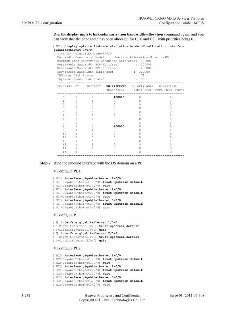
Run the display mpls te link-administration bandwidth-allocation command again, and youcan view that the bandwidth has been allocated for CT0 and CT1 with priorities being 0.
[PE1] display mpls te link-administration bandwidth-allocation interface gigabitethernet 3/0/0 Link ID: GigabitEthernet3/0/0 Bandwidth Constraint Model : Maximum Allocation Model (MAM) Maximum Link Reservable Bandwidth(Kbit/sec): 300000 Reservable Bandwidth BC0(Kbit/sec) : 100000 Reservable Bandwidth BC1(Kbit/sec) : 200000 Downstream Bandwidth (Kbit/sec) : 300000 IPUpdown Link Status : UP PhysicalUpdown Link Status : UP ---------------------------------------------------------------------- TE-CLASS CT PRIORITY BW RESERVED BW AVAILABLE DOWNSTREAM (Kbit/sec) (Kbit/sec) RSVPLSPNODE COUNT ---------------------------------------------------------------------- 0 0 0 100000 0 0 1 0 1 0 0 0 2 0 2 0 0 0 3 0 3 0 0 0 4 0 4 0 0 0 5 0 5 0 0 0 6 0 6 0 0 0 7 0 7 0 0 0 8 1 0 200000 0 0 9 1 1 0 0 0 10 1 2 0 0 0 11 1 3 0 0 0 12 1 4 0 0 0 13 1 5 0 0 0 14 1 6 0 0 0 15 1 7 0 0 0 ----------------------------------------------------------------------
Step 7 Bind the inbound interface with the DS domain on a PE.
# Configure PE1.
[PE1] interface gigabitethernet 1/0/0[PE1-GigabitEthernet1/0/0] trust upstream default[PE1-GigabitEthernet1/0/0] quit[PE1] interface gigabitethernet 2/0/0[PE1-GigabitEthernet2/0/0] trust upstream default[PE1-GigabitEthernet2/0/0] quit[PE1] interface gigabitethernet 3/0/0[PE1-GigabitEthernet3/0/0] trust upstream default[PE1-GigabitEthernet3/0/0] quit
# Configure P.
[P] interface gigabitethernet 1/0/0[P-GigabitEthernet1/0/0] trust upstream default[P-GigabitEthernet1/0/0] quit[P] interface gigabitethernet 2/0/0[P-GigabitEthernet2/0/0] trust upstream default[P-GigabitEthernet2/0/0] quit
# Configure PE2.
[PE2] interface gigabitethernet 1/0/0[PE2-GigabitEthernet1/0/0] trust upstream default[PE2-GigabitEthernet1/0/0] quit[PE2] interface gigabitethernet 2/0/0[PE2-GigabitEthernet2/0/0] trust upstream default[PE2-GigabitEthernet2/0/0] quit[PE2] interface gigabitethernet 3/0/0[PE2-GigabitEthernet3/0/0] trust upstream default[PE2-GigabitEthernet3/0/0] quit
3 MPLS TE ConfigurationHUAWEI CX600 Metro Services Platform
Configuration Guide - MPLS
3-232 Huawei Proprietary and ConfidentialCopyright © Huawei Technologies Co., Ltd.
Issue 01 (2011-05-30)
After the configuration, run the display diffserv domain default command on a PE, and youcan view information about the default traffic policy for traffic classification in a DS domain.
Take the display on PE1 as an example.
[PE1] display diffserv domain defaultDiffserv domain name:default ... mpls-exp-inbound 0 phb be green mpls-exp-inbound 1 phb af1 green mpls-exp-inbound 2 phb af2 green mpls-exp-inbound 3 phb af3 green mpls-exp-inbound 4 phb af4 green mpls-exp-inbound 5 phb ef green mpls-exp-inbound 6 phb cs6 green mpls-exp-inbound 7 phb cs7 green mpls-exp-outbound be green map 0 mpls-exp-outbound af1 green map 1 mpls-exp-outbound af1 yellow map 1 mpls-exp-outbound af1 red map 1 mpls-exp-outbound af2 green map 2 mpls-exp-outbound af2 yellow map 2 mpls-exp-outbound af2 red map 2 mpls-exp-outbound af3 green map 3 mpls-exp-outbound af3 yellow map 3 mpls-exp-outbound af3 red map 3 mpls-exp-outbound af4 green map 4 mpls-exp-outbound af4 yellow map 4 mpls-exp-outbound af4 red map 4 mpls-exp-outbound ef green map 5 mpls-exp-outbound cs6 green map 6 mpls-exp-outbound cs7 green map 7 ...
NOTETake note of the preceding items that appear in the display diffserv domain default command output.Information in "..." can be ignored.
Step 8 Configure the mapping of the CT and service type on the PEs and P.
# Configure PE1.
[PE1] ct-flow-mapping mapping1[PE1-ct-flow-mapping-mapping1] map ct 0 to ef pq[PE1-ct-flow-mapping-mapping1] map ct 1 to be lpq[PE1-ct-flow-mapping-mapping1] ct-flow-mapping commit[PE1-ct-flow-mapping-mapping1] quit[PE1] interface gigabitethernet 3/0/0[PE1-GigabitEthernet3/0/0] mpls te ct-flow-mapping mapping1[PE1-GigabitEthernet3/0/0] mpls te ct-bandwidth unshared[PE1-GigabitEthernet3/0/0] quit
# Configure PE2.
[PE2] ct-flow-mapping mapping1[PE2-ct-flow-mapping-mapping1] map ct 0 to ef pq[PE2-ct-flow-mapping-mapping1] map ct 1 to be lpq[PE2-ct-flow-mapping-mapping1] ct-flow-mapping commit[PE2-ct-flow-mapping-mapping1] quit[PE2] interface gigabitethernet 3/0/0[PE2-GigabitEthernet3/0/0] mpls te ct-flow-mapping mapping1[PE2-GigabitEthernet3/0/0] mpls te ct-bandwidth unshared[PE2-GigabitEthernet3/0/0] quit
# After the configuration, run the display ct-flow-mapping command on PEs, and you can viewthe mapping relationship between CTs and flow queues.
Take the display on PE1 as an example.
HUAWEI CX600 Metro Services PlatformConfiguration Guide - MPLS 3 MPLS TE Configuration
Issue 01 (2011-05-30) Huawei Proprietary and ConfidentialCopyright © Huawei Technologies Co., Ltd.
3-233
[PE1] display ct-flow-mapping allTotle template: 2 template-name:defaultmap CT 0 to be lpqmap CT 1 to af1 wfqmap CT 2 to af2 wfqmap CT 3 to af3 wfqmap CT 4 to af4 wfqmap CT 5 to ef pqmap CT 6 to cs6 pqmap CT 7 to cs6 pq
template-name:mapping1map CT 0 to ef pqmap CT 1 to be lpq
Step 9 Create the MP-IBGP peer relationship between PEs, and create the EBGP peer relationshipbetween PEs and CEs.
# Configure PE1.
[PE1] bgp 100[PE1-bgp] peer 3.3.3.9 as-number 100[PE1-bgp] peer 3.3.3.9 connect-interface loopback 1[PE1-bgp] ipv4-family vpnv4[PE1-bgp-af-vpnv4] peer 3.3.3.9 enable[PE1-bgp-af-vpnv4] quit[PE1-bgp] ipv4-family vpn-instance vpna[PE1-bgp-vpna] peer 10.1.1.1 as-number 65410[PE1-bgp-vpna] import-route direct[PE1-bgp-vpna] quit[PE1-bgp] ipv4-family vpn-instance vpnb[PE1-bgp-vpnb] peer 10.2.1.1 as-number 65420[PE1-bgp-vpnb] import-route direct[PE1-bgp-vpnb] quit
NOTEThe configuration of PE2 is similar to that of PE1. The configuration detail is not provided here.
# Configure CE1.
[CE1] bgp 65410[CE1-bgp] peer 10.1.1.2 as-number 100[CE1-bgp] import-route direct
NOTEThe configuration of other CEs (CE2, CE3, and CE4) is similar to that of CE1. The configuration detailsare not provided here.
After the configuration, run the display bgp vpnv4 all peer command on the PE, and you cansee that the BGP peer relationship is created between PEs and its status is Established.
[PE1] display bgp vpnv4 all peerBGP local router ID : 1.1.1.9 Local AS number : 100 Total number of peers : 3 Peers in established state : 3Peer V AS MsgRcvd MsgSent OutQ Up/Down State PrefRcv
3.3.3.9 4 100 12 18 0 00:09:38 Established 0 Peer of vpn instance: vpn instance vpna :10.1.1.1 4 65410 25 25 0 00:17:57 Established 1 vpn instance vpnb :10.2.1.1 4 65420 21 22 0 00:17:10 Established 1
Step 10 Configure a tunnel policy on the PE.
# Configure PE1.
3 MPLS TE ConfigurationHUAWEI CX600 Metro Services Platform
Configuration Guide - MPLS
3-234 Huawei Proprietary and ConfidentialCopyright © Huawei Technologies Co., Ltd.
Issue 01 (2011-05-30)
[PE1] tunnel-policy policya[PE1-tunnel-policy-policya] tunnel binding destination 3.3.3.9 te tunnel 3/0/0[PE1-tunnel-policy-policya] quit[PE1] tunnel-policy policyb[PE1-tunnel-policy-policyb] tunnel binding destination 3.3.3.9 te tunnel 3/0/1[PE1-tunnel-policy-policyb] quit
# Configure PE2.
[PE2] tunnel-policy policya[PE2-tunnel-policy-policya] tunnel binding destination 1.1.1.9 te tunnel 3/0/0[PE2-tunnel-policy-policya] quit[PE2] tunnel-policy policyb[PE2-tunnel-policy-policyb] tunnel binding destination 1.1.1.9 te tunnel 3/0/1[PE2-tunnel-policy-policyb] quit
Step 11 Configure VPN instances on PEs and connect CEs to PEs.
# Configure PE1.
[PE1] ip vpn-instance vpna
[PE1-vpn-instance-vpna] ipv4-family[PE1-vpn-instance-vpna-af-ipv4] route-distinguisher 100:1[PE1-vpn-instance-vpna-af-ipv4] vpn-target 111:1 both[PE1-vpn-instance-vpna-af-ipv4] tnl-policy policya[PE1-vpn-instance-vpna-af-ipv] quit[PE1-vpn-instance-vpna] quit[PE1] ip vpn-instance vpnb
[PE1-vpn-instance-vpnb] ipv4-family[PE1-vpn-instance-vpnb-af-ipv4] route-distinguisher 100:2[PE1-vpn-instance-vpnb-af-ipv4] vpn-target 222:2 both[PE1-vpn-instance-vpnb-af-ipv4] tnl-policy policyb[PE1-vpn-instance-vpnb-af-ipv4] quit[PE1-vpn-instance-vpnb] quit[PE1] interface gigabitethernet 1/0/0[PE1-GigabitEthernet1/0/0] ip binding vpn-instance vpna[PE1-GigabitEthernet1/0/0] ip address 10.1.1.2 24[PE1-GigabitEthernet1/0/0] quit[PE1] interface gigabitethernet 2/0/0[PE1-GigabitEthernet2/0/0] ip binding vpn-instance vpnb[PE1-GigabitEthernet2/0/0] ip address 10.2.1.2 24[PE1-GigabitEthernet2/0/0] quit
# Configure PE2.
[PE2] ip vpn-instance vpna
[PE2-vpn-instance-vpna] ipv4-family[PE2-vpn-instance-vpna-af-ipv4] route-distinguisher 200:1[PE2-vpn-instance-vpna-af-ipv4] vpn-target 111:1 both[PE2-vpn-instance-vpna-af-ipv4] tnl-policy policya[PE2-vpn-instance-vpna-af-ipv4] quit[PE2-vpn-instance-vpna] quit[PE2] ip vpn-instance vpnb
[PE2-vpn-instance-vpnb] ipv4-family[PE2-vpn-instance-vpnb-af-ipv4] route-distinguisher 200:2[PE2-vpn-instance-vpnb-af-ipv4] vpn-target 222:2 both[PE2-vpn-instance-vpnb-af-ipv4] tnl-policy policyb[PE2-vpn-instance-vpnb-af-ipv4] quit[PE2-vpn-instance-vpnb] quit[PE2] interface gigabitethernet 1/0/0[PE2-GigabitEthernet1/0/0] ip binding vpn-instance vpna[PE2-GigabitEthernet1/0/0] ip address 10.3.1.2 24[PE2-GigabitEthernet1/0/0] quit[PE2] interface gigabitethernet 2/0/0[PE2-GigabitEthernet2/0/0] ip binding vpn-instance vpnb
HUAWEI CX600 Metro Services PlatformConfiguration Guide - MPLS 3 MPLS TE Configuration
Issue 01 (2011-05-30) Huawei Proprietary and ConfidentialCopyright © Huawei Technologies Co., Ltd.
3-235
[PE2-GigabitEthernet2/0/0] ip address 10.4.1.2 24[PE2-GigabitEthernet2/0/0] quit
# Configure IP addresses for interfaces of CEs. The configuration details are not provided here.
After the configuration, run the display ipvpn-instance verbose command on the PE, and youcan view the configuration of VPN instances. PEs can ping through the CEs connecting to thePEs.
Step 12 Verify the configuration.
After the configuration, connect CE1, CE2, CE3, and CE4 to port 1, port 2, port 3, and port 4of a tester. Inject EF traffic from port 1 and port 2 to port 2 and port 1 respectively, with thebandwidth being 100 Mbit/s. Inject BE traffic from port 3 and port 4 to port 2 and port 1respectively, with the bandwidth being 200 Mbit/s. All the packets are not discarded and thejitter of EF traffic is shorter than 50 ms.
----End
Configuration Filesl Configuration file of PE1
# sysname PE1#ip vpn-instance vpna ipv4-family route-distinguisher 100:1 tnl-policy policya vpn-target 111:1 export-extcommunity vpn-target 111:1 import-extcommunity#ip vpn-instance vpnb ipv4-family route-distinguisher 100:2 tnl-policy policyb vpn-target 222:2 export-extcommunity vpn-target 222:2 import-extcommunity# mpls lsr-id 1.1.1.9 mpls mpls te mpls te ds-te bcm mam#ct-flow-mapping mapping1 map ct 0 to ef pq map ct 1 to be lpq ct-flow-mapping commit#interface GigabitEthernet1/0/0 undo shutdown ip binding vpn-instance vpna ip address 10.1.1.2 255.255.255.0 trust upstream default#interface GigabitEthernet2/0/0 undo shutdown ip binding vpn-instance vpnb ip address 10.2.1.2 255.255.255.0 trust upstream default#interface GigabitEthernet3/0/0 undo shutdown ip address 172.1.1.1 255.255.255.0 mpls mpls te
3 MPLS TE ConfigurationHUAWEI CX600 Metro Services Platform
Configuration Guide - MPLS
3-236 Huawei Proprietary and ConfidentialCopyright © Huawei Technologies Co., Ltd.
Issue 01 (2011-05-30)
mpls te bandwidth max-reservable-bandwidth 300000 mpls te bandwidth bc0 100000 bc1 200000 trust upstream default mpls te ct-flow-mapping mapping1 mpls te ct-bandwidth unshared#interface LoopBack1 ip address 1.1.1.9 255.255.255.255#interface Tunnel3/0/0 description For VPN-A_EF ip address unnumbered interface LoopBack1 tunnel-protocol mpls te destination 3.3.3.9 mpls te tunnel-id 300 mpls te signal-protocol cr-static mpls te commit#interface Tunnel3/0/1 description For VPN-B_BE ip address unnumbered interface LoopBack1 tunnel-protocol mpls te destination 3.3.3.9 mpls te tunnel-id 301 mpls te signal-protocol cr-static mpls te commit#bgp 100 peer 3.3.3.9 as-number 100 peer 3.3.3.9 connect-interface LoopBack1 # ipv4-family unicast undo synchronization peer 3.3.3.9 enable# ipv4-family vpnv4 policy vpn-target peer 3.3.3.9 enable # ipv4-family vpn-instance vpna peer 10.1.1.1 as-number 65410 import-route direct# ipv4-family vpn-instance vpnb peer 10.2.1.1 as-number 65420 import-route direct#ospf 1 opaque-capability enable area 0.0.0.0 network 172.1.1.0 0.0.0.255 network 1.1.1.9 0.0.0.0 mpls-te enable# static-cr-lsp ingress tunnel-interface Tunnel 3/0/0 destination 3.3.3.9 nexthop 172.1.1.2 out-label 100 bandwidth ct0 100000 static-cr-lsp ingress tunnel-interface tunnel 3/0/1 destination 3.3.3.9 nexthop 172.1.1.2 out-label 200 bandwidth ct1 200000 static-cr-lsp egress VPN-A_EF incoming-interface gigabitethernet 3/0/0 in-label 101 static-cr-lsp egress VPN-B_BE incoming-interface gigabitethernet 3/0/0 in-label 201#tunnel-policy policya tunnel binding destination 3.3.3.9 te Tunnel3/0/0#tunnel-policy policyb tunnel binding destination 3.3.3.9 te Tunnel3/0/1
HUAWEI CX600 Metro Services PlatformConfiguration Guide - MPLS 3 MPLS TE Configuration
Issue 01 (2011-05-30) Huawei Proprietary and ConfidentialCopyright © Huawei Technologies Co., Ltd.
3-237
#return
l Configuration file of P# sysname P# mpls lsr-id 2.2.2.9 mpls mpls te mpls te ds-te bcm mam#interface GigabitEthernet1/0/0 undo shutdown ip address 172.1.1.2 255.255.255.0 mpls mpls te mpls te bandwidth max-reservable-bandwidth 300000 mpls te bandwidth bc0 100000 bc1 200000 trust upstream default#interface GigabitEthernet2/0/0 undo shutdown ip address 172.2.1.1 255.255.255.0 mpls mpls te mpls te bandwidth max-reservable-bandwidth 300000 mpls te bandwidth bc0 100000 bc1 200000 trust upstream default#interface LoopBack1 ip address 2.2.2.9 255.255.255.255#ospf 1 opaque-capability enable area 0.0.0.0 network 172.1.1.0 0.0.0.255 network 172.2.1.0 0.0.0.255 network 2.2.2.9 0.0.0.0 mpls-te enable# static-cr-lsp transit VPN-A_EF-1to2 incoming-interface gigabitethernet1/0/0 in-label 100 nexthop 172.2.1.2 out-label 100 bandwidth ct0 100000 static-cr-lsp transit VPN-B_BE-1to2 incoming-interface gigabitethernet1/0/0 in-label 200 nexthop 172.2.1.2 out-label 200 bandwidth ct1 200000 static-cr-lsp transit VPN-A_EF-2to1 incoming-interface gigabitethernet2/0/0 in-label 101 nexthop 172.1.1.1 out-label 101 bandwidth ct0 100000 static-cr-lsp transit VPN-B_BE-2to1 incoming-interface gigabitethernet2/0/0 in-label 201 nexthop 172.1.1.1 out-label 201 bandwidth ct1 200000#return
l Configuration file of PE2# sysname PE2#ip vpn-instance vpna ipv4-family route-distinguisher 200:1 tnl-policy policya vpn-target 111:1 export-extcommunity vpn-target 111:1 import-extcommunity#ip vpn-instance vpnb ipv4-family route-distinguisher 200:2 tnl-policy policyb vpn-target 222:2 export-extcommunity vpn-target 222:2 import-extcommunity#
3 MPLS TE ConfigurationHUAWEI CX600 Metro Services Platform
Configuration Guide - MPLS
3-238 Huawei Proprietary and ConfidentialCopyright © Huawei Technologies Co., Ltd.
Issue 01 (2011-05-30)
mpls lsr-id 3.3.3.9 mpls mpls te mpls te ds-te bcm mam#ct-flow-mapping mapping1 map ct 0 to ef pq map ct 1 to be lpq ct-flow-mapping commit#interface GigabitEthernet1/0/0 undo shutdown ip binding vpn-instance vpna ip address 10.3.1.2 255.255.255.0 trust upstream default#interface GigabitEthernet2/0/0 undo shutdown ip binding vpn-instance vpnb ip address 10.4.1.2 255.255.255.0 trust upstream default#interface GigabitEthernet3/0/0 undo shutdown ip address 172.2.1.2 255.255.255.0 mpls mpls te mpls te bandwidth max-reservable-bandwidth 300000 mpls te bandwidth bc0 100000 bc1 200000 trust upstream default mpls te ct-flow-mapping mapping1 mpls te ct-bandwidth unshared#interface LoopBack1 ip address 3.3.3.9 255.255.255.255#interface Tunnel3/0/0 description For VPN-A_EF ip address unnumbered interface LoopBack1 tunnel-protocol mpls te destination 1.1.1.9 mpls te tunnel-id 300 mpls te signal-protocol cr-static mpls te commit#interface Tunnel3/0/1 description For VPN-B_BE ip address unnumbered interface LoopBack1 tunnel-protocol mpls te destination 1.1.1.9 mpls te tunnel-id 301 mpls te signal-protocol cr-static mpls te commit#bgp 100 peer 1.1.1.9 as-number 100 peer 1.1.1.9 connect-interface LoopBack1 # ipv4-family unicast undo synchronization peer 1.1.1.9 enable # ipv4-family vpnv4 policy vpn-target peer 1.1.1.9 enable # ipv4-family vpn-instance vpna peer 10.3.1.1 as-number 65430 import-route direct
HUAWEI CX600 Metro Services PlatformConfiguration Guide - MPLS 3 MPLS TE Configuration
Issue 01 (2011-05-30) Huawei Proprietary and ConfidentialCopyright © Huawei Technologies Co., Ltd.
3-239
# ipv4-family vpn-instance vpnb peer 10.4.1.1 as-number 65440 import-route direct#ospf 1 opaque-capability enable area 0.0.0.0 network 172.2.1.0 0.0.0.255 network 3.3.3.9 0.0.0.0 mpls-te enable# static-cr-lsp egress VPN-A_EF incoming-interface gigabitethernet 3/0/0 in-label 100 static-cr-lsp egress VPN-B_BE incoming-interface gigabitethernet 3/0/0 in-label 200 static-cr-lsp ingress tunnel-interface tunnel 3/0/0 destination 1.1.1.9 nexthop 172.2.1.1 out-label 101 bandwidth ct0 100000 static-cr-lsp ingress tunnel-interface tunnel 3/0/1 destination 1.1.1.9 nexthop 172.2.1.1 out-label 201 bandwidth ct1 200000#tunnel-policy policya tunnel binding destination 1.1.1.9 te Tunnel3/0/0#tunnel-policy policyb tunnel binding destination 1.1.1.9 te Tunnel3/0/1#return
l Configuration file of CE1# sysname CE1#interface GigabitEthernet1/0/0 undo shutdown ip address 10.1.1.1 255.255.255.0#bgp 65410 peer 10.1.1.2 as-number 100 # ipv4-family unicast undo synchronization import-route direct peer 10.1.1.2 enable#return
l Configuration file of CE2# sysname CE2#interface GigabitEthernet1/0/0 undo shutdown ip address 10.2.1.1 255.255.255.0#bgp 65420 peer 10.2.1.2 as-number 100 # ipv4-family unicast undo synchronization import-route direct peer 10.2.1.2 enable#return
l Configuration file of CE3# sysname CE3#interface GigabitEthernet1/0/0
3 MPLS TE ConfigurationHUAWEI CX600 Metro Services Platform
Configuration Guide - MPLS
3-240 Huawei Proprietary and ConfidentialCopyright © Huawei Technologies Co., Ltd.
Issue 01 (2011-05-30)
undo shutdown ip address 10.3.1.1 255.255.255.0#bgp 65430 peer 10.3.1.2 as-number 100 # ipv4-family unicast undo synchronization import-route direct peer 10.3.1.2 enable#return
l Configuration file of CE4# sysname CE4#interface GigabitEthernet1/0/0 undo shutdown ip address 10.4.1.1 255.255.255.0#bgp 65440 peer 10.4.1.2 as-number 100 # ipv4-family unicast undo synchronization import-route direct peer 10.4.1.2 enable#return
3.26.12 Example for Configuring a DS-TE Tunnel in IETF Mode(RDM)
This section provides an example for configuring a DS-TE tunnel in IETF mode.
Networking RequirementsAs shown in Figure 3-13, PEs and P on the MPLS backbone network are enabled with OSPFto communicate with each other. The P, however, does not support MPLS LDP. PE1 accessesVPN-A and PE2 accesses VPN-B. An LDP LSP needs to be set up along the path PE3 --> PE1--> P --> PE2 --> PE4. As shown in Figure 3-13, VPN-A transmits EF and AF traffic; VPN-Btransmits EF, AF, and BE traffic; the LDP LSP transmits BE traffic. The QoS requirements ofdifferent types of traffic are as follows:
Traffic Bandwidth Jitter
EF traffic on VPN-A 100 Mbit/s Shorter than 50 ms
AF traffic on VPN-A 50 Mbit/s Shorter than 200 ms
EF traffic on VPN-B 100 Mbit/s Shorter than 50 ms
AF traffic on VPN-B 50 Mbit/s Shorter than 200 ms
BE traffic on VPN-B 50 Mbit/s None
BE traffic on the LDP LSP 50 Mbit/s None
The networking requires that a DS-TE tunnel be set up between PE1 and PE2 to transmit thepreceding traffic and meet different QoS requirements of different traffic types. The bandwidth
HUAWEI CX600 Metro Services PlatformConfiguration Guide - MPLS 3 MPLS TE Configuration
Issue 01 (2011-05-30) Huawei Proprietary and ConfidentialCopyright © Huawei Technologies Co., Ltd.
3-241
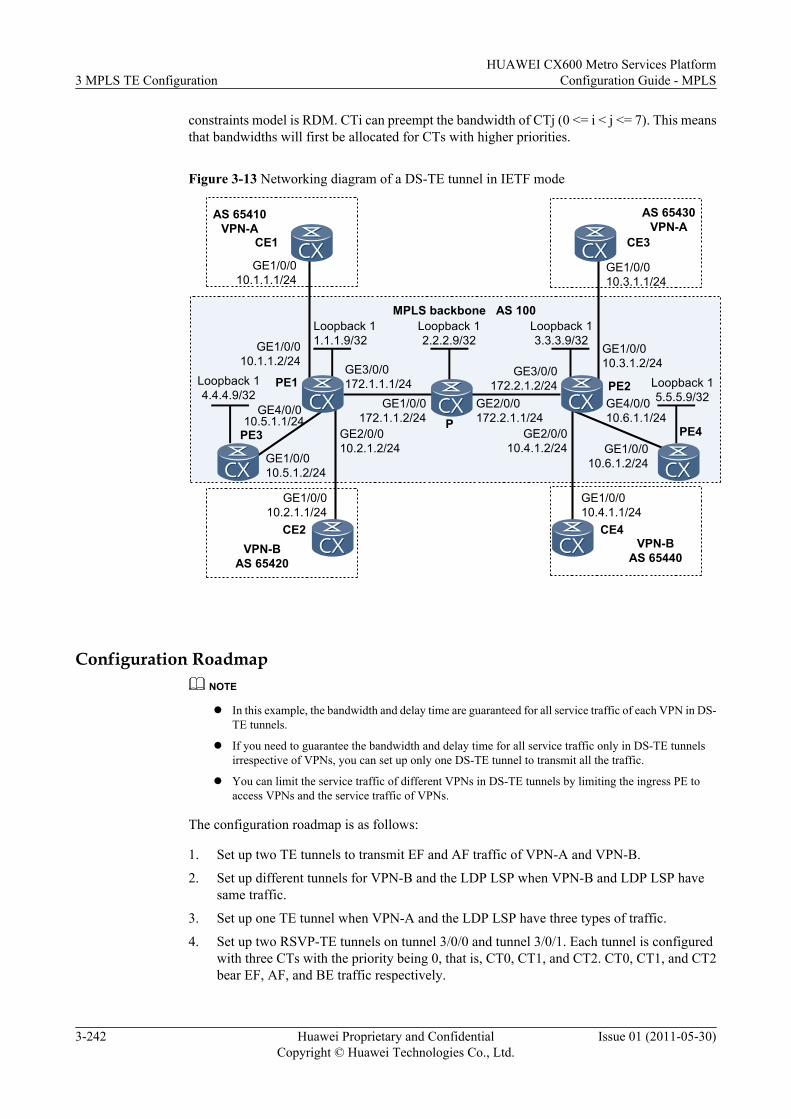
constraints model is RDM. CTi can preempt the bandwidth of CTj (0 <= i < j <= 7). This meansthat bandwidths will first be allocated for CTs with higher priorities.
Figure 3-13 Networking diagram of a DS-TE tunnel in IETF mode
AS 65410VPN-A
CE1
GE1/0/010.1.1.1/24
Loopback 11.1.1.9/32
Loopback 14.4.4.9/32
PE1
GE1/0/010.1.1.2/24
GE4/0/010.5.1.1/24
GE1/0/010.5.1.2/24
GE1/0/010.3.1.1/24
CE3
AS 65430VPN-A
MPLS backbone AS 100Loopback 12.2.2.9/32
Loopback 13.3.3.9/32
GE3/0/0172.1.1.1/24
GE2/0/010.2.1.2/24
GE1/0/0172.1.1.2/24
GE1/0/010.2.1.1/24
GE2/0/0172.2.1.1/24
GE3/0/0172.2.1.2/24
VPN-BAS 65420
VPN-BAS 65440
GE2/0/010.4.1.2/24
GE1/0/010.4.1.1/24
GE4/0/010.6.1.1/24
GE1/0/010.6.1.2/24
GE1/0/010.3.1.2/24
CE4
PE4
PE2
CE2
PPE3
Loopback 15.5.5.9/32
Configuration RoadmapNOTE
l In this example, the bandwidth and delay time are guaranteed for all service traffic of each VPN in DS-TE tunnels.
l If you need to guarantee the bandwidth and delay time for all service traffic only in DS-TE tunnelsirrespective of VPNs, you can set up only one DS-TE tunnel to transmit all the traffic.
l You can limit the service traffic of different VPNs in DS-TE tunnels by limiting the ingress PE toaccess VPNs and the service traffic of VPNs.
The configuration roadmap is as follows:
1. Set up two TE tunnels to transmit EF and AF traffic of VPN-A and VPN-B.
2. Set up different tunnels for VPN-B and the LDP LSP when VPN-B and LDP LSP havesame traffic.
3. Set up one TE tunnel when VPN-A and the LDP LSP have three types of traffic.
4. Set up two RSVP-TE tunnels on tunnel 3/0/0 and tunnel 3/0/1. Each tunnel is configuredwith three CTs with the priority being 0, that is, CT0, CT1, and CT2. CT0, CT1, and CT2bear EF, AF, and BE traffic respectively.
3 MPLS TE ConfigurationHUAWEI CX600 Metro Services Platform
Configuration Guide - MPLS
3-242 Huawei Proprietary and ConfidentialCopyright © Huawei Technologies Co., Ltd.
Issue 01 (2011-05-30)
5. CT2 and CT1 of tunnel 3/0/0 transmit EF and AF traffic of VPN-A. CT0 of tunnel 3/0/0transmits BE traffic of the LDP LSP. CT2, CT1, and CT0 of tunnel 3/0/1 transmit EF, AF,and BE traffic of VPN-B.
6. Paths of the two tunnels are the same. Thus, the BCi bandwidth should be equal to or greaterthan the total bandwidth of CTi to CT7 of all the TE tunnels. In addition, the maximumreservable bandwidth for links should be equal to or greater than the bandwidth of BC0.Therefore, the bandwidth relationships between BCi and CT1 to CT7 is as follows:Bandwidth of BC2 on the link => Bandwidth of CT2 of Tunnel 3/0/0 and Tunnel 3/0/1 =100 Mbit/sBandwidth of BC1 => Bandwidth of BC2 + CT1 of Tunnel 3/0/0 and Tunnel 3/0/1 = 200Mbit/sBandwidth of BC0 => Bandwidth of BC1 + Bandwidth of CT0 of Tunnel 3/0/0 + Bandwidthof CT0 of Tunnel 3/0/1 = 400 Mbit/sReservable bandwidth of the link = Bandwidth of BC0 = 400 Mbit/s
7. Services of the same type in two TE tunnels require the same bandwidth and jitter.Therefore, the CT template is used to configure the TE tunnel.
Data PreparationTo configure a DS-TE tunnel in IETF mode (RDM), you need the following data.
l LSR IDs of PEs and Pl Interface number of the TE tunnell TE-class mapping tablel Values of the maximum reservable bandwidth and BC bandwidth of linksl VPN-A instance name, VPN-B instance name, route-distinguisher, VPN target, and name
of the tunnel policy
ProcedureStep 1 Configure IP addresses for interfaces on PEs and the P. Enable OSPF to ensure that PEs and the
P can communicate with each other.
The configuration details are not provided here.
After the configurations, OSPF adjacencies can be created between PE1, P, and PE2. By usingthe display ospf peer command, you can view that the status of the adjacency is Full. By usingthe display ip routing-table command, you can see that PEs can learn the Loopback1 routefrom each other.
Step 2 Configure LSR ID and enable MPLS on each PE and P. Enable MPLS TE and RSVP-TE onPE1, PE2, and the P. Enable MPLS LDP on all PEs.
# Configure PE3.
<PE3> system-view[PE3] mpls lsr-id 4.4.4.9[PE3] mpls[PE3-mpls] quit[PE3] mpls ldp[PE3-mpls-ldp] quit[PE3] interface gigabitethernet 1/0/0[PE3-GigabitEthernet1/0/0] mpls[PE3-GigabitEthernet1/0/0] mpls ldp[PE3-GigabitEthernet1/0/0] quit
HUAWEI CX600 Metro Services PlatformConfiguration Guide - MPLS 3 MPLS TE Configuration
Issue 01 (2011-05-30) Huawei Proprietary and ConfidentialCopyright © Huawei Technologies Co., Ltd.
3-243
# Configure PE1.
<PE1> system-view[PE1] mpls lsr-id 1.1.1.9[PE1] mpls[PE1-mpls] mpls te[PE1-mpls] mpls rsvp-te[PE1-mpls] quit[PE1] mpls ldp[PE1-mpls-ldp] quit[PE1] interface gigabitethernet 3/0/0[PE1-GigabitEthernet3/0/0] mpls[PE1-GigabitEthernet3/0/0] mpls te[PE1-GigabitEthernet3/0/0] mpls rsvp-te[PE1-GigabitEthernet3/0/0] quit[PE1] interface gigabitethernet 4/0/0[PE1-GigabitEthernet4/0/0] mpls[PE1-GigabitEthernet4/0/0] mpls ldp[PE1-GigabitEthernet4/0/0] quit
# Configure the P.
<P> system-view[P] mpls lsr-id 2.2.2.9[P] mpls[P-mpls] mpls te[P-mpls] mpls rsvp-te[P-mpls] quit[P] interface gigabitethernet 1/0/0[P-GigabitEthernet1/0/0] mpls[P-GigabitEthernet1/0/0] mpls te[P-GigabitEthernet1/0/0] mpls rsvp-te[P-GigabitEthernet1/0/0] quit[P] interface gigabitethernet 2/0/0[P-GigabitEthernet2/0/0] mpls[P-GigabitEthernet2/0/0] mpls te[P-GigabitEthernet2/0/0] mpls rsvp-te[P-GigabitEthernet2/0/0] quit
# Configure PE2.
<PE2> system-view[PE2] mpls lsr-id 3.3.3.9[PE2] mpls[PE2-mpls] mpls te[PE2-mpls] mpls rsvp-te[PE2-mpls] quit[PE2] mpls ldp[PE2-mpls] quit[PE2] interface gigabitethernet 3/0/0[PE2-GigabitEthernet3/0/0] mpls[PE2-GigabitEthernet3/0/0] mpls te[PE2-GigabitEthernet3/0/0] mpls rsvp-te[PE2-GigabitEthernet3/0/0] quit[PE2] interface gigabitethernet 4/0/0[PE2-GigabitEthernet4/0/0] mpls[PE2-GigabitEthernet4/0/0] mpls ldp[PE2-GigabitEthernet4/0/0] quit
# Configure PE4.
<PE4> system-view[PE4] mpls lsr-id 5.5.5.9[PE4] mpls[PE4-mpls] quit[PE4] mpls ldp[PE4-mpls-ldp] quit[PE4] interface gigabitethernet 1/0/0[PE4-GigabitEthernet1/0/0] mpls
3 MPLS TE ConfigurationHUAWEI CX600 Metro Services Platform
Configuration Guide - MPLS
3-244 Huawei Proprietary and ConfidentialCopyright © Huawei Technologies Co., Ltd.
Issue 01 (2011-05-30)
[PE4-GigabitEthernet1/0/0] mpls ldp[PE4-GigabitEthernet1/0/0] quit
After the configuration, run the display mpls rsvp-te interface command on PE1, PE2, or theP, and you can view interfaces enabled with RSVP and information about RSVP. Run the displaympls ldp lsp command on PE1, PE2, PE3, or PE4, and you can see that an LDP LSP existsbetween PE3 and PE1, and between PE2 and PE4.
Step 3 Configure OSPF TE on PE1, PE2, and the P and enable CSPF.
# Configure OSPF TE on PE1, PE2, and the P and enable CSPF on the ingress of the TE tunnel.
# Configure PE1.[PE1] ospf 1[PE1-ospf-1] opaque-capability enable[PE1-ospf-1] area 0[PE1-ospf-1-area-0.0.0.0] mpls-te enable[PE1-ospf-1-area-0.0.0.0] quit[PE1-ospf-1] quit[PE1] mpls[PE1-mpls] mpls te cspf
# Configure P.[P] ospf 1[P-ospf-1] opaque-capability enable[P-ospf-1] area 0[P-ospf-1-area-0.0.0.0] mpls-te enable[P-ospf-1-area-0.0.0.0] quit[P-ospf-1] quit
# Configure PE2.[PE2] ospf 1[PE2-ospf-1] opaque-capability enable[PE2-ospf-1] area 0[PE2-ospf-1-area-0.0.0.0] mpls-te enable[PE2-ospf-1-area-0.0.0.0] quit[PE2-ospf-1] quit[PE2] mpls[PE2-mpls] mpls te cspf[PE2-mpls] quit
After the configuration, run the display ospf mpls-te command, and you can view the TE LSAinformation in the OSPF Link State Database (LSDB).
Step 4 Configure the DS-TE mode and the bandwidth constraints model on PE1, PE2, and the P.
# Configure PE1.[PE1] mpls[PE1-mpls] mpls te ds-te mode ietf[PE1-mpls] mpls te ds-te bcm rdm[PE1-mpls] quit
# Configure P.[P] mpls[P-mpls] mpls te ds-te mode ietf[P-mpls] mpls te ds-te bcm rdm[P-mpls] quit
# Configure PE2.[PE2] mpls[PE2-mpls] mpls te ds-te mode ietf[PE2-mpls] mpls te ds-te bcm rdm[PE2-mpls] quit
HUAWEI CX600 Metro Services PlatformConfiguration Guide - MPLS 3 MPLS TE Configuration
Issue 01 (2011-05-30) Huawei Proprietary and ConfidentialCopyright © Huawei Technologies Co., Ltd.
3-245
After the configuration, run the display mpls te ds-te summary command on a PE or P, andyou can view information about DS-TE configuration.
Take the display on PE1 as an example.
[PE1] display mpls te ds-te summaryDS-TE IETF Supported :YESDS-TE MODE :IETFBandwidth Constraint Model :RDMTEClass Mapping (default):TE-Class ID Class Type PriorityTE-Class 0 0 0TE-Class 1 1 0TE-Class 2 2 0TE-Class 3 3 0TE-Class 4 0 7TE-Class 5 1 7TE-Class 6 2 7TE-Class 7 3 7
Step 5 Configure link bandwidth on the PEs and P.
# Configure PE1.
[PE1] interface gigabitethernet 3/0/0[PE1-GigabitEthernet3/0/0] mpls te bandwidth max-reservable-bandwidth 400000[PE1-GigabitEthernet3/0/0] mpls te bandwidth bc0 400000 bc1 200000 bc2 100000[PE1-GigabitEthernet3/0/0] quit
# Configure the P.
[P] interface gigabitethernet 1/0/0[P-GigabitEthernet1/0/0] mpls te bandwidth max-reservable-bandwidth 400000[P-GigabitEthernet1/0/0] mpls te bandwidth bc0 400000 bc1 200000 bc2 100000[P-GigabitEthernet1/0/0] quit[P] interface gigabitethernet 2/0/0[P-GigabitEthernet2/0/0] mpls te bandwidth max-reservable-bandwidth 400000[P-GigabitEthernet2/0/0] mpls te bandwidth bc0 400000 bc1 200000 bc2 100000[P-GigabitEthernet2/0/0] quit
# Configure PE2.
[PE2] interface gigabitethernet 3/0/0[PE2-GigabitEthernet3/0/0] mpls te bandwidth max-reservable-bandwidth 400000[PE2-GigabitEthernet3/0/0] mpls te bandwidth bc0 400000 bc1 200000 bc2 100000[PE2-GigabitEthernet3/0/0] quit
After the configuration, run the display mpls te link-administration bandwidth-allocationinterface command on the PE and you can view information about BC bandwidth allocation forinterfaces.
Take the display on PE1 as an example.
[PE1] display mpls te link-administration bandwidth-allocation interface gigabitethernet 3/0/0 Link ID: GigabitEthernet3/0/0 Bandwidth Constraint Model : Russian Dolls Model (RDM) Maximum Link Reservable Bandwidth(Kbit/sec): 400000 Reservable Bandwidth BC0(Kbit/sec) : 400000 Reservable Bandwidth BC1(Kbit/sec) : 200000 Reservable Bandwidth BC2(Kbit/sec) : 100000 Reservable Bandwidth BC3(Kbit/sec) : 0 Reservable Bandwidth BC4(Kbit/sec) : 0 Reservable Bandwidth BC5(Kbit/sec) : 0 Reservable Bandwidth BC6(Kbit/sec) : 0 Reservable Bandwidth BC7(Kbit/sec) : 0 Downstream Bandwidth (Kbit/sec) : 0 IPUpdown Link Status : UP PhysicalUpdown Link Status : UP
3 MPLS TE ConfigurationHUAWEI CX600 Metro Services Platform
Configuration Guide - MPLS
3-246 Huawei Proprietary and ConfidentialCopyright © Huawei Technologies Co., Ltd.
Issue 01 (2011-05-30)
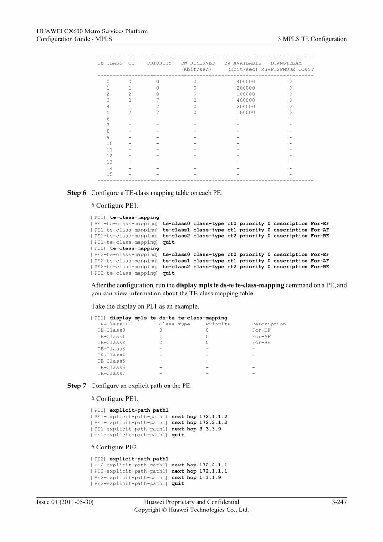
---------------------------------------------------------------------- TE-CLASS CT PRIORITY BW RESERVED BW AVAILABLE DOWNSTREAM (Kbit/sec) (Kbit/sec) RSVPLSPNODE COUNT ---------------------------------------------------------------------- 0 0 0 0 400000 0 1 1 0 0 200000 0 2 2 0 0 100000 0 3 0 7 0 400000 0 4 1 7 0 200000 0 5 2 7 0 100000 0 6 - - - - - 7 - - - - - 8 - - - - - 9 - - - - - 10 - - - - - 11 - - - - - 12 - - - - - 13 - - - - - 14 - - - - - 15 - - - - - ----------------------------------------------------------------------
Step 6 Configure a TE-class mapping table on each PE.
# Configure PE1.[PE1] te-class-mapping[PE1-te-class-mapping] te-class0 class-type ct0 priority 0 description For-EF[PE1-te-class-mapping] te-class1 class-type ct1 priority 0 description For-AF[PE1-te-class-mapping] te-class2 class-type ct2 priority 0 description For-BE[PE1-te-class-mapping] quit [PE2] te-class-mapping[PE2-te-class-mapping] te-class0 class-type ct0 priority 0 description For-EF[PE2-te-class-mapping] te-class1 class-type ct1 priority 0 description For-AF[PE2-te-class-mapping] te-class2 class-type ct2 priority 0 description For-BE[PE2-te-class-mapping] quit
After the configuration, run the display mpls te ds-te te-class-mapping command on a PE, andyou can view information about the TE-class mapping table.
Take the display on PE1 as an example.[PE1] display mpls te ds-te te-class-mapping TE-Class ID Class Type Priority Description TE-Class0 0 0 For-EF TE-Class1 1 0 For-AF TE-Class2 2 0 For-BE TE-Class3 - - - TE-Class4 - - - TE-Class5 - - - TE-Class6 - - - TE-Class7 - - -
Step 7 Configure an explicit path on the PE.
# Configure PE1.[PE1] explicit-path path1[PE1-explicit-path-path1] next hop 172.1.1.2[PE1-explicit-path-path1] next hop 172.2.1.2[PE1-explicit-path-path1] next hop 3.3.3.9[PE1-explicit-path-path1] quit
# Configure PE2.[PE2] explicit-path path1[PE2-explicit-path-path1] next hop 172.2.1.1[PE2-explicit-path-path1] next hop 172.1.1.1[PE2-explicit-path-path1] next hop 1.1.1.9[PE2-explicit-path-path1] quit
HUAWEI CX600 Metro Services PlatformConfiguration Guide - MPLS 3 MPLS TE Configuration
Issue 01 (2011-05-30) Huawei Proprietary and ConfidentialCopyright © Huawei Technologies Co., Ltd.
3-247
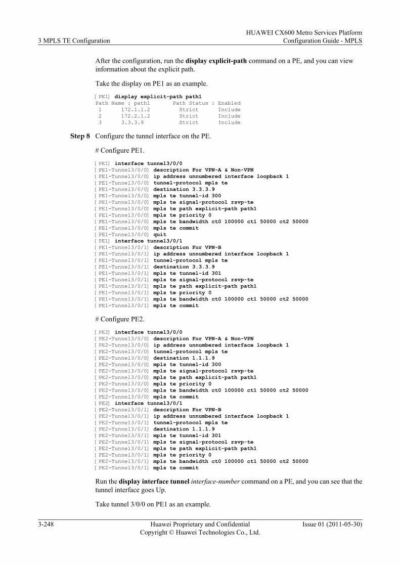
After the configuration, run the display explicit-path command on a PE, and you can viewinformation about the explicit path.
Take the display on PE1 as an example.
[PE1] display explicit-path path1Path Name : path1 Path Status : Enabled 1 172.1.1.2 Strict Include 2 172.2.1.2 Strict Include 3 3.3.3.9 Strict Include
Step 8 Configure the tunnel interface on the PE.
# Configure PE1.
[PE1] interface tunnel3/0/0[PE1-Tunnel3/0/0] description For VPN-A & Non-VPN[PE1-Tunnel3/0/0] ip address unnumbered interface loopback 1[PE1-Tunnel3/0/0] tunnel-protocol mpls te[PE1-Tunnel3/0/0] destination 3.3.3.9[PE1-Tunnel3/0/0] mpls te tunnel-id 300[PE1-Tunnel3/0/0] mpls te signal-protocol rsvp-te[PE1-Tunnel3/0/0] mpls te path explicit-path path1[PE1-Tunnel3/0/0] mpls te priority 0[PE1-Tunnel3/0/0] mpls te bandwidth ct0 100000 ct1 50000 ct2 50000[PE1-Tunnel3/0/0] mpls te commit[PE1-Tunnel3/0/0] quit[PE1] interface tunnel3/0/1[PE1-Tunnel3/0/1] description For VPN-B[PE1-Tunnel3/0/1] ip address unnumbered interface loopback 1[PE1-Tunnel3/0/1] tunnel-protocol mpls te[PE1-Tunnel3/0/1] destination 3.3.3.9[PE1-Tunnel3/0/1] mpls te tunnel-id 301[PE1-Tunnel3/0/1] mpls te signal-protocol rsvp-te[PE1-Tunnel3/0/1] mpls te path explicit-path path1[PE1-Tunnel3/0/1] mpls te priority 0[PE1-Tunnel3/0/1] mpls te bandwidth ct0 100000 ct1 50000 ct2 50000[PE1-Tunnel3/0/1] mpls te commit
# Configure PE2.
[PE2] interface tunnel3/0/0[PE2-Tunnel3/0/0] description For VPN-A & Non-VPN[PE2-Tunnel3/0/0] ip address unnumbered interface loopback 1[PE2-Tunnel3/0/0] tunnel-protocol mpls te[PE2-Tunnel3/0/0] destination 1.1.1.9[PE2-Tunnel3/0/0] mpls te tunnel-id 300[PE2-Tunnel3/0/0] mpls te signal-protocol rsvp-te[PE2-Tunnel3/0/0] mpls te path explicit-path path1[PE2-Tunnel3/0/0] mpls te priority 0[PE2-Tunnel3/0/0] mpls te bandwidth ct0 100000 ct1 50000 ct2 50000[PE2-Tunnel3/0/0] mpls te commit[PE2] interface tunnel3/0/1[PE2-Tunnel3/0/1] description For VPN-B[PE2-Tunnel3/0/1] ip address unnumbered interface loopback 1[PE2-Tunnel3/0/1] tunnel-protocol mpls te[PE2-Tunnel3/0/1] destination 1.1.1.9[PE2-Tunnel3/0/1] mpls te tunnel-id 301[PE2-Tunnel3/0/1] mpls te signal-protocol rsvp-te[PE2-Tunnel3/0/1] mpls te path explicit-path path1[PE2-Tunnel3/0/1] mpls te priority 0[PE2-Tunnel3/0/1] mpls te bandwidth ct0 100000 ct1 50000 ct2 50000[PE2-Tunnel3/0/1] mpls te commit
Run the display interface tunnel interface-number command on a PE, and you can see that thetunnel interface goes Up.
Take tunnel 3/0/0 on PE1 as an example.
3 MPLS TE ConfigurationHUAWEI CX600 Metro Services Platform
Configuration Guide - MPLS
3-248 Huawei Proprietary and ConfidentialCopyright © Huawei Technologies Co., Ltd.
Issue 01 (2011-05-30)
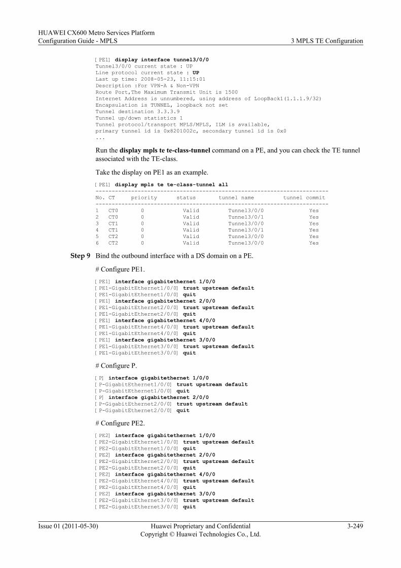
[PE1] display interface tunnel3/0/0Tunnel3/0/0 current state : UPLine protocol current state : UPLast up time: 2008-05-23, 11:15:01Description :For VPN-A & Non-VPNRoute Port,The Maximum Transmit Unit is 1500Internet Address is unnumbered, using address of LoopBack1(1.1.1.9/32)Encapsulation is TUNNEL, loopback not setTunnel destination 3.3.3.9Tunnel up/down statistics 1Tunnel protocol/transport MPLS/MPLS, ILM is available,primary tunnel id is 0x8201002c, secondary tunnel id is 0x0...
Run the display mpls te te-class-tunnel command on a PE, and you can check the TE tunnelassociated with the TE-class.
Take the display on PE1 as an example.[PE1] display mpls te te-class-tunnel all------------------------------------------------------------------------No. CT priority status tunnel name tunnel commit------------------------------------------------------------------------1 CT0 0 Valid Tunnel3/0/0 Yes2 CT0 0 Valid Tunnel3/0/1 Yes3 CT1 0 Valid Tunnel3/0/0 Yes4 CT1 0 Valid Tunnel3/0/1 Yes5 CT2 0 Valid Tunnel3/0/0 Yes6 CT2 0 Valid Tunnel3/0/0 Yes
Step 9 Bind the outbound interface with a DS domain on a PE.
# Configure PE1.[PE1] interface gigabitethernet 1/0/0[PE1-GigabitEthernet1/0/0] trust upstream default[PE1-GigabitEthernet1/0/0] quit[PE1] interface gigabitethernet 2/0/0[PE1-GigabitEthernet2/0/0] trust upstream default[PE1-GigabitEthernet2/0/0] quit[PE1] interface gigabitethernet 4/0/0[PE1-GigabitEthernet4/0/0] trust upstream default[PE1-GigabitEthernet4/0/0] quit[PE1] interface gigabitethernet 3/0/0[PE1-GigabitEthernet3/0/0] trust upstream default[PE1-GigabitEthernet3/0/0] quit
# Configure P.[P] interface gigabitethernet 1/0/0[P-GigabitEthernet1/0/0] trust upstream default[P-GigabitEthernet1/0/0] quit[P] interface gigabitethernet 2/0/0[P-GigabitEthernet2/0/0] trust upstream default[P-GigabitEthernet2/0/0] quit
# Configure PE2.[PE2] interface gigabitethernet 1/0/0[PE2-GigabitEthernet1/0/0] trust upstream default[PE2-GigabitEthernet1/0/0] quit[PE2] interface gigabitethernet 2/0/0[PE2-GigabitEthernet2/0/0] trust upstream default[PE2-GigabitEthernet2/0/0] quit[PE2] interface gigabitethernet 4/0/0[PE2-GigabitEthernet4/0/0] trust upstream default[PE2-GigabitEthernet4/0/0] quit[PE2] interface gigabitethernet 3/0/0[PE2-GigabitEthernet3/0/0] trust upstream default[PE2-GigabitEthernet3/0/0] quit
HUAWEI CX600 Metro Services PlatformConfiguration Guide - MPLS 3 MPLS TE Configuration
Issue 01 (2011-05-30) Huawei Proprietary and ConfidentialCopyright © Huawei Technologies Co., Ltd.
3-249
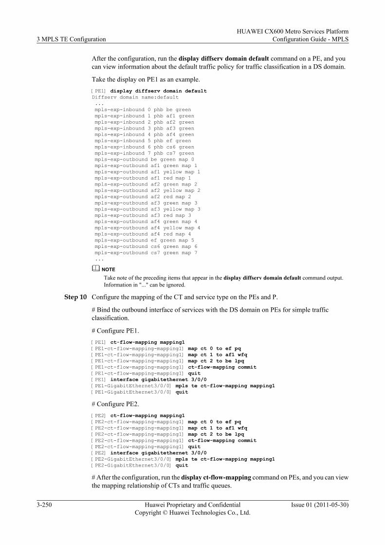
After the configuration, run the display diffserv domain default command on a PE, and youcan view information about the default traffic policy for traffic classification in a DS domain.
Take the display on PE1 as an example.[PE1] display diffserv domain defaultDiffserv domain name:default ... mpls-exp-inbound 0 phb be green mpls-exp-inbound 1 phb af1 green mpls-exp-inbound 2 phb af2 green mpls-exp-inbound 3 phb af3 green mpls-exp-inbound 4 phb af4 green mpls-exp-inbound 5 phb ef green mpls-exp-inbound 6 phb cs6 green mpls-exp-inbound 7 phb cs7 green mpls-exp-outbound be green map 0 mpls-exp-outbound af1 green map 1 mpls-exp-outbound af1 yellow map 1 mpls-exp-outbound af1 red map 1 mpls-exp-outbound af2 green map 2 mpls-exp-outbound af2 yellow map 2 mpls-exp-outbound af2 red map 2 mpls-exp-outbound af3 green map 3 mpls-exp-outbound af3 yellow map 3 mpls-exp-outbound af3 red map 3 mpls-exp-outbound af4 green map 4 mpls-exp-outbound af4 yellow map 4 mpls-exp-outbound af4 red map 4 mpls-exp-outbound ef green map 5 mpls-exp-outbound cs6 green map 6 mpls-exp-outbound cs7 green map 7 ...
NOTETake note of the preceding items that appear in the display diffserv domain default command output.Information in "..." can be ignored.
Step 10 Configure the mapping of the CT and service type on the PEs and P.
# Bind the outbound interface of services with the DS domain on PEs for simple trafficclassification.
# Configure PE1.[PE1] ct-flow-mapping mapping1[PE1-ct-flow-mapping-mapping1] map ct 0 to ef pq[PE1-ct-flow-mapping-mapping1] map ct 1 to af1 wfq[PE1-ct-flow-mapping-mapping1] map ct 2 to be lpq[PE1-ct-flow-mapping-mapping1] ct-flow-mapping commit[PE1-ct-flow-mapping-mapping1] quit[PE1] interface gigabitethernet 3/0/0[PE1-GigabitEthernet3/0/0] mpls te ct-flow-mapping mapping1[PE1-GigabitEthernet3/0/0] quit
# Configure PE2.[PE2] ct-flow-mapping mapping1[PE2-ct-flow-mapping-mapping1] map ct 0 to ef pq[PE2-ct-flow-mapping-mapping1] map ct 1 to af1 wfq[PE2-ct-flow-mapping-mapping1] map ct 2 to be lpq[PE2-ct-flow-mapping-mapping1] ct-flow-mapping commit[PE2-ct-flow-mapping-mapping1] quit[PE2] interface gigabitethernet 3/0/0[PE2-GigabitEthernet3/0/0] mpls te ct-flow-mapping mapping1[PE2-GigabitEthernet3/0/0] quit
# After the configuration, run the display ct-flow-mapping command on PEs, and you can viewthe mapping relationship of CTs and traffic queues.
3 MPLS TE ConfigurationHUAWEI CX600 Metro Services Platform
Configuration Guide - MPLS
3-250 Huawei Proprietary and ConfidentialCopyright © Huawei Technologies Co., Ltd.
Issue 01 (2011-05-30)
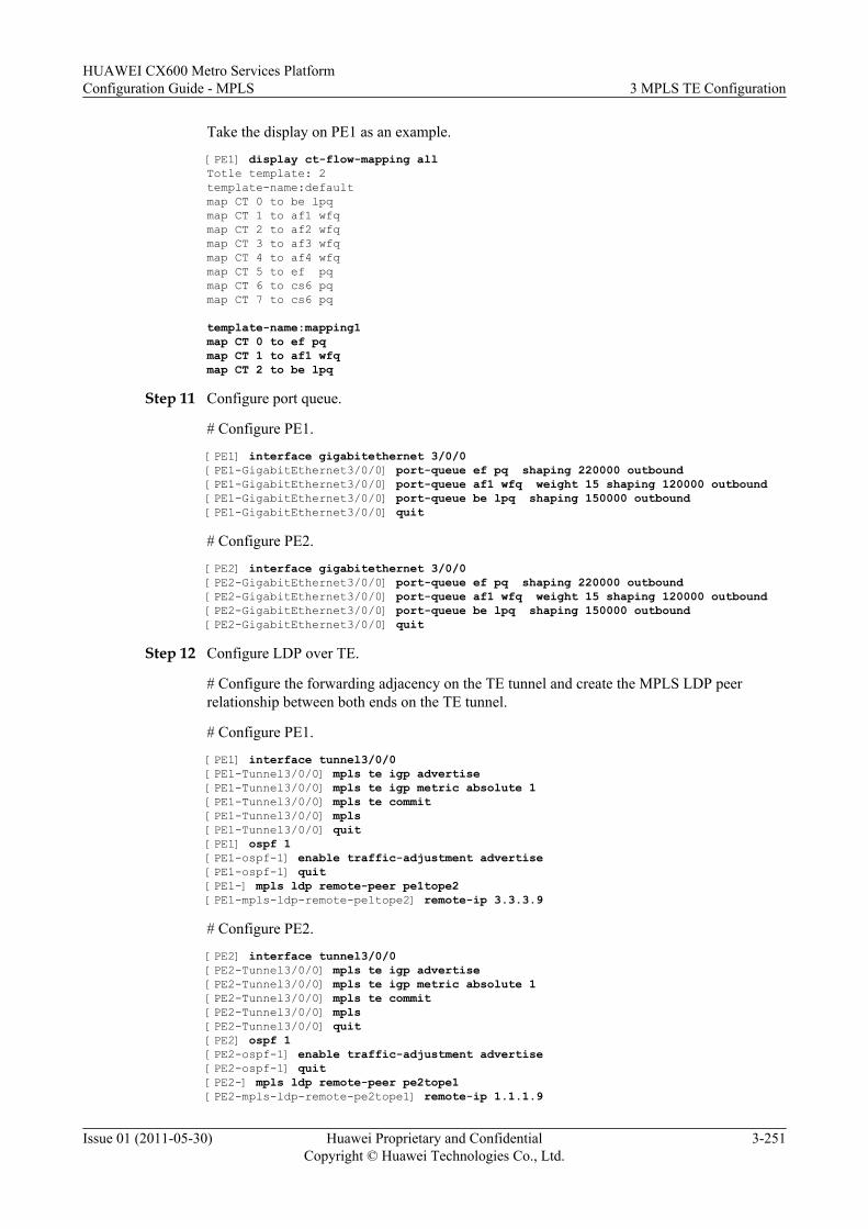
Take the display on PE1 as an example.
[PE1] display ct-flow-mapping allTotle template: 2 template-name:defaultmap CT 0 to be lpqmap CT 1 to af1 wfqmap CT 2 to af2 wfqmap CT 3 to af3 wfqmap CT 4 to af4 wfqmap CT 5 to ef pqmap CT 6 to cs6 pqmap CT 7 to cs6 pq
template-name:mapping1map CT 0 to ef pqmap CT 1 to af1 wfqmap CT 2 to be lpq
Step 11 Configure port queue.
# Configure PE1.
[PE1] interface gigabitethernet 3/0/0[PE1-GigabitEthernet3/0/0] port-queue ef pq shaping 220000 outbound[PE1-GigabitEthernet3/0/0] port-queue af1 wfq weight 15 shaping 120000 outbound[PE1-GigabitEthernet3/0/0] port-queue be lpq shaping 150000 outbound[PE1-GigabitEthernet3/0/0] quit
# Configure PE2.
[PE2] interface gigabitethernet 3/0/0[PE2-GigabitEthernet3/0/0] port-queue ef pq shaping 220000 outbound[PE2-GigabitEthernet3/0/0] port-queue af1 wfq weight 15 shaping 120000 outbound[PE2-GigabitEthernet3/0/0] port-queue be lpq shaping 150000 outbound[PE2-GigabitEthernet3/0/0] quit
Step 12 Configure LDP over TE.
# Configure the forwarding adjacency on the TE tunnel and create the MPLS LDP peerrelationship between both ends on the TE tunnel.
# Configure PE1.
[PE1] interface tunnel3/0/0[PE1-Tunnel3/0/0] mpls te igp advertise[PE1-Tunnel3/0/0] mpls te igp metric absolute 1[PE1-Tunnel3/0/0] mpls te commit[PE1-Tunnel3/0/0] mpls[PE1-Tunnel3/0/0] quit[PE1] ospf 1[PE1-ospf-1] enable traffic-adjustment advertise[PE1-ospf-1] quit[PE1-] mpls ldp remote-peer pe1tope2[PE1-mpls-ldp-remote-pe1tope2] remote-ip 3.3.3.9
# Configure PE2.
[PE2] interface tunnel3/0/0[PE2-Tunnel3/0/0] mpls te igp advertise[PE2-Tunnel3/0/0] mpls te igp metric absolute 1[PE2-Tunnel3/0/0] mpls te commit[PE2-Tunnel3/0/0] mpls[PE2-Tunnel3/0/0] quit[PE2] ospf 1[PE2-ospf-1] enable traffic-adjustment advertise[PE2-ospf-1] quit[PE2-] mpls ldp remote-peer pe2tope1[PE2-mpls-ldp-remote-pe2tope1] remote-ip 1.1.1.9
HUAWEI CX600 Metro Services PlatformConfiguration Guide - MPLS 3 MPLS TE Configuration
Issue 01 (2011-05-30) Huawei Proprietary and ConfidentialCopyright © Huawei Technologies Co., Ltd.
3-251
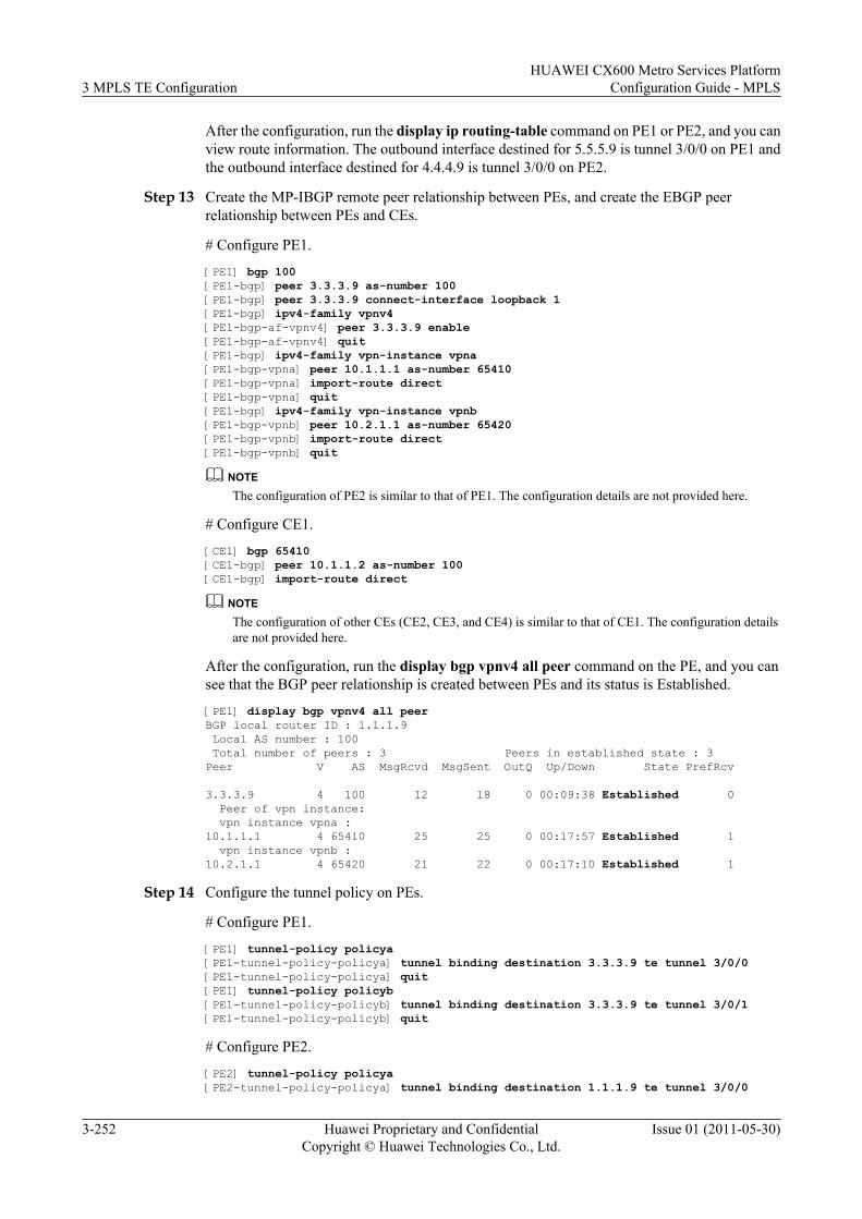
After the configuration, run the display ip routing-table command on PE1 or PE2, and you canview route information. The outbound interface destined for 5.5.5.9 is tunnel 3/0/0 on PE1 andthe outbound interface destined for 4.4.4.9 is tunnel 3/0/0 on PE2.
Step 13 Create the MP-IBGP remote peer relationship between PEs, and create the EBGP peerrelationship between PEs and CEs.
# Configure PE1.
[PE1] bgp 100[PE1-bgp] peer 3.3.3.9 as-number 100[PE1-bgp] peer 3.3.3.9 connect-interface loopback 1[PE1-bgp] ipv4-family vpnv4[PE1-bgp-af-vpnv4] peer 3.3.3.9 enable[PE1-bgp-af-vpnv4] quit[PE1-bgp] ipv4-family vpn-instance vpna[PE1-bgp-vpna] peer 10.1.1.1 as-number 65410[PE1-bgp-vpna] import-route direct[PE1-bgp-vpna] quit[PE1-bgp] ipv4-family vpn-instance vpnb[PE1-bgp-vpnb] peer 10.2.1.1 as-number 65420[PE1-bgp-vpnb] import-route direct[PE1-bgp-vpnb] quit
NOTEThe configuration of PE2 is similar to that of PE1. The configuration details are not provided here.
# Configure CE1.
[CE1] bgp 65410[CE1-bgp] peer 10.1.1.2 as-number 100[CE1-bgp] import-route direct
NOTEThe configuration of other CEs (CE2, CE3, and CE4) is similar to that of CE1. The configuration detailsare not provided here.
After the configuration, run the display bgp vpnv4 all peer command on the PE, and you cansee that the BGP peer relationship is created between PEs and its status is Established.
[PE1] display bgp vpnv4 all peerBGP local router ID : 1.1.1.9 Local AS number : 100 Total number of peers : 3 Peers in established state : 3Peer V AS MsgRcvd MsgSent OutQ Up/Down State PrefRcv
3.3.3.9 4 100 12 18 0 00:09:38 Established 0 Peer of vpn instance: vpn instance vpna :10.1.1.1 4 65410 25 25 0 00:17:57 Established 1 vpn instance vpnb :10.2.1.1 4 65420 21 22 0 00:17:10 Established 1
Step 14 Configure the tunnel policy on PEs.
# Configure PE1.
[PE1] tunnel-policy policya[PE1-tunnel-policy-policya] tunnel binding destination 3.3.3.9 te tunnel 3/0/0[PE1-tunnel-policy-policya] quit[PE1] tunnel-policy policyb[PE1-tunnel-policy-policyb] tunnel binding destination 3.3.3.9 te tunnel 3/0/1[PE1-tunnel-policy-policyb] quit
# Configure PE2.
[PE2] tunnel-policy policya[PE2-tunnel-policy-policya] tunnel binding destination 1.1.1.9 te tunnel 3/0/0
3 MPLS TE ConfigurationHUAWEI CX600 Metro Services Platform
Configuration Guide - MPLS
3-252 Huawei Proprietary and ConfidentialCopyright © Huawei Technologies Co., Ltd.
Issue 01 (2011-05-30)
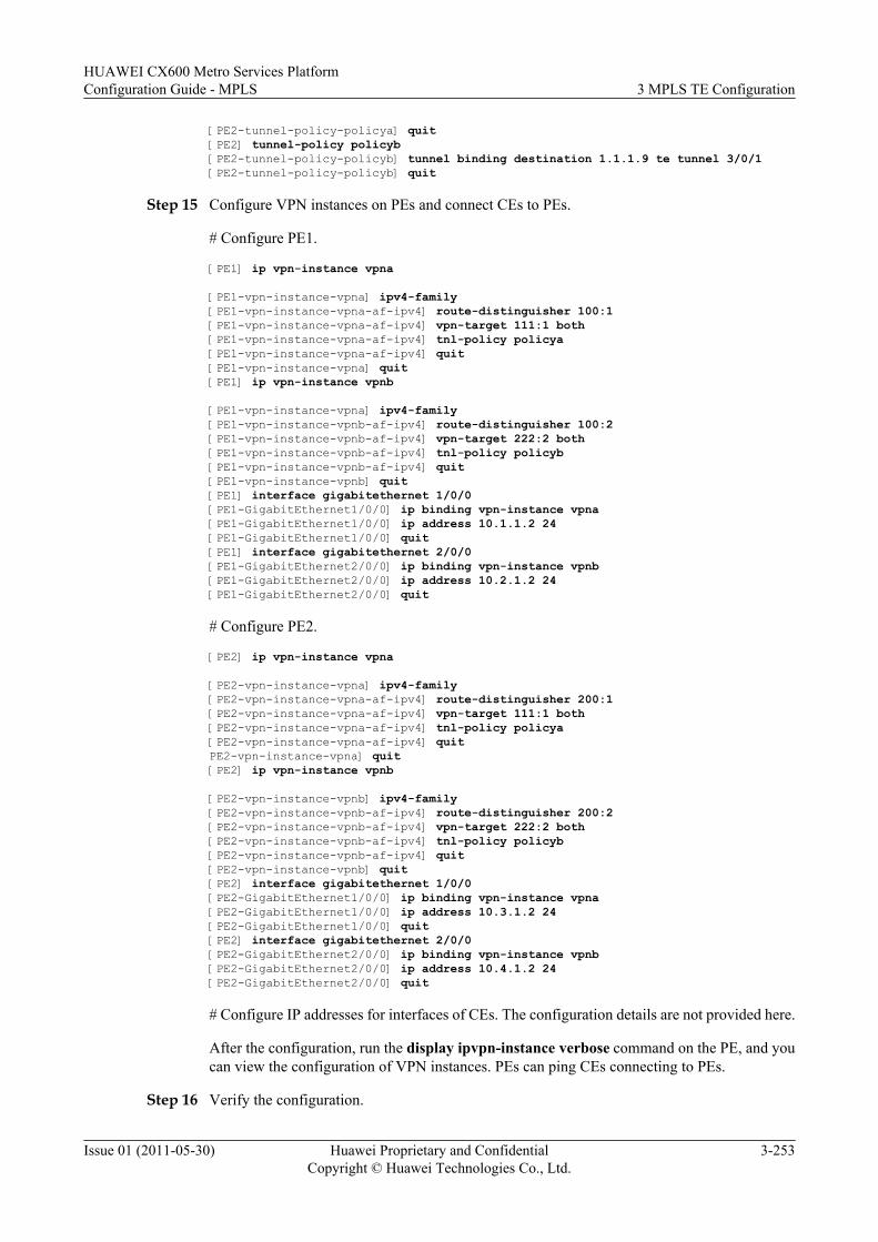
[PE2-tunnel-policy-policya] quit[PE2] tunnel-policy policyb[PE2-tunnel-policy-policyb] tunnel binding destination 1.1.1.9 te tunnel 3/0/1[PE2-tunnel-policy-policyb] quit
Step 15 Configure VPN instances on PEs and connect CEs to PEs.
# Configure PE1.
[PE1] ip vpn-instance vpna
[PE1-vpn-instance-vpna] ipv4-family[PE1-vpn-instance-vpna-af-ipv4] route-distinguisher 100:1[PE1-vpn-instance-vpna-af-ipv4] vpn-target 111:1 both[PE1-vpn-instance-vpna-af-ipv4] tnl-policy policya[PE1-vpn-instance-vpna-af-ipv4] quit[PE1-vpn-instance-vpna] quit[PE1] ip vpn-instance vpnb
[PE1-vpn-instance-vpna] ipv4-family[PE1-vpn-instance-vpnb-af-ipv4] route-distinguisher 100:2[PE1-vpn-instance-vpnb-af-ipv4] vpn-target 222:2 both[PE1-vpn-instance-vpnb-af-ipv4] tnl-policy policyb[PE1-vpn-instance-vpnb-af-ipv4] quit[PE1-vpn-instance-vpnb] quit[PE1] interface gigabitethernet 1/0/0[PE1-GigabitEthernet1/0/0] ip binding vpn-instance vpna[PE1-GigabitEthernet1/0/0] ip address 10.1.1.2 24[PE1-GigabitEthernet1/0/0] quit[PE1] interface gigabitethernet 2/0/0[PE1-GigabitEthernet2/0/0] ip binding vpn-instance vpnb[PE1-GigabitEthernet2/0/0] ip address 10.2.1.2 24[PE1-GigabitEthernet2/0/0] quit
# Configure PE2.
[PE2] ip vpn-instance vpna
[PE2-vpn-instance-vpna] ipv4-family[PE2-vpn-instance-vpna-af-ipv4] route-distinguisher 200:1[PE2-vpn-instance-vpna-af-ipv4] vpn-target 111:1 both[PE2-vpn-instance-vpna-af-ipv4] tnl-policy policya[PE2-vpn-instance-vpna-af-ipv4] quitPE2-vpn-instance-vpna] quit[PE2] ip vpn-instance vpnb
[PE2-vpn-instance-vpnb] ipv4-family[PE2-vpn-instance-vpnb-af-ipv4] route-distinguisher 200:2[PE2-vpn-instance-vpnb-af-ipv4] vpn-target 222:2 both[PE2-vpn-instance-vpnb-af-ipv4] tnl-policy policyb[PE2-vpn-instance-vpnb-af-ipv4] quit[PE2-vpn-instance-vpnb] quit[PE2] interface gigabitethernet 1/0/0[PE2-GigabitEthernet1/0/0] ip binding vpn-instance vpna[PE2-GigabitEthernet1/0/0] ip address 10.3.1.2 24[PE2-GigabitEthernet1/0/0] quit[PE2] interface gigabitethernet 2/0/0[PE2-GigabitEthernet2/0/0] ip binding vpn-instance vpnb[PE2-GigabitEthernet2/0/0] ip address 10.4.1.2 24[PE2-GigabitEthernet2/0/0] quit
# Configure IP addresses for interfaces of CEs. The configuration details are not provided here.
After the configuration, run the display ipvpn-instance verbose command on the PE, and youcan view the configuration of VPN instances. PEs can ping CEs connecting to PEs.
Step 16 Verify the configuration.
HUAWEI CX600 Metro Services PlatformConfiguration Guide - MPLS 3 MPLS TE Configuration
Issue 01 (2011-05-30) Huawei Proprietary and ConfidentialCopyright © Huawei Technologies Co., Ltd.
3-253
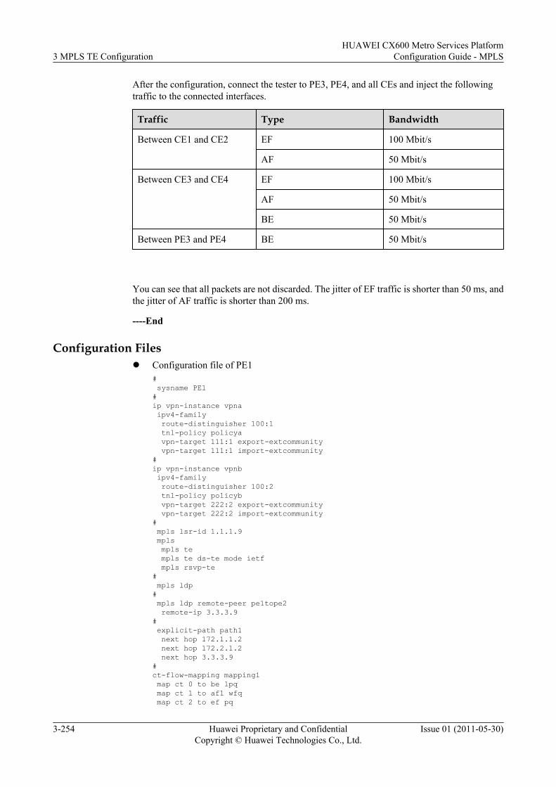
After the configuration, connect the tester to PE3, PE4, and all CEs and inject the followingtraffic to the connected interfaces.
Traffic Type Bandwidth
Between CE1 and CE2 EF 100 Mbit/s
AF 50 Mbit/s
Between CE3 and CE4 EF 100 Mbit/s
AF 50 Mbit/s
BE 50 Mbit/s
Between PE3 and PE4 BE 50 Mbit/s
You can see that all packets are not discarded. The jitter of EF traffic is shorter than 50 ms, andthe jitter of AF traffic is shorter than 200 ms.
----End
Configuration Filesl Configuration file of PE1
# sysname PE1#ip vpn-instance vpna ipv4-family route-distinguisher 100:1 tnl-policy policya vpn-target 111:1 export-extcommunity vpn-target 111:1 import-extcommunity#ip vpn-instance vpnb ipv4-family route-distinguisher 100:2 tnl-policy policyb vpn-target 222:2 export-extcommunity vpn-target 222:2 import-extcommunity# mpls lsr-id 1.1.1.9 mpls mpls te mpls te ds-te mode ietf mpls rsvp-te# mpls ldp# mpls ldp remote-peer pe1tope2 remote-ip 3.3.3.9# explicit-path path1 next hop 172.1.1.2 next hop 172.2.1.2 next hop 3.3.3.9#ct-flow-mapping mapping1 map ct 0 to be lpq map ct 1 to af1 wfq map ct 2 to ef pq
3 MPLS TE ConfigurationHUAWEI CX600 Metro Services Platform
Configuration Guide - MPLS
3-254 Huawei Proprietary and ConfidentialCopyright © Huawei Technologies Co., Ltd.
Issue 01 (2011-05-30)
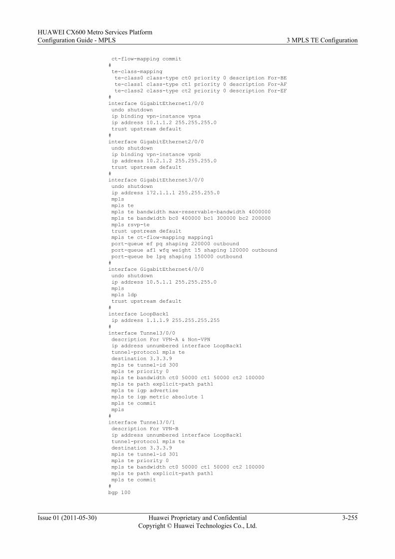
ct-flow-mapping commit# te-class-mapping te-class0 class-type ct0 priority 0 description For-BE te-class1 class-type ct1 priority 0 description For-AF te-class2 class-type ct2 priority 0 description For-EF#interface GigabitEthernet1/0/0 undo shutdown ip binding vpn-instance vpna ip address 10.1.1.2 255.255.255.0 trust upstream default#interface GigabitEthernet2/0/0 undo shutdown ip binding vpn-instance vpnb ip address 10.2.1.2 255.255.255.0 trust upstream default#interface GigabitEthernet3/0/0 undo shutdown ip address 172.1.1.1 255.255.255.0 mpls mpls te mpls te bandwidth max-reservable-bandwidth 4000000 mpls te bandwidth bc0 400000 bc1 300000 bc2 200000 mpls rsvp-te trust upstream default mpls te ct-flow-mapping mapping1 port-queue ef pq shaping 220000 outbound port-queue af1 wfq weight 15 shaping 120000 outbound port-queue be lpq shaping 150000 outbound#interface GigabitEthernet4/0/0 undo shutdown ip address 10.5.1.1 255.255.255.0 mpls mpls ldp trust upstream default#interface LoopBack1 ip address 1.1.1.9 255.255.255.255#interface Tunnel3/0/0 description For VPN-A & Non-VPN ip address unnumbered interface LoopBack1 tunnel-protocol mpls te destination 3.3.3.9 mpls te tunnel-id 300 mpls te priority 0 mpls te bandwidth ct0 50000 ct1 50000 ct2 100000 mpls te path explicit-path path1 mpls te igp advertise mpls te igp metric absolute 1 mpls te commit mpls#interface Tunnel3/0/1 description For VPN-B ip address unnumbered interface LoopBack1 tunnel-protocol mpls te destination 3.3.3.9 mpls te tunnel-id 301 mpls te priority 0 mpls te bandwidth ct0 50000 ct1 50000 ct2 100000 mpls te path explicit-path path1 mpls te commit#bgp 100
HUAWEI CX600 Metro Services PlatformConfiguration Guide - MPLS 3 MPLS TE Configuration
Issue 01 (2011-05-30) Huawei Proprietary and ConfidentialCopyright © Huawei Technologies Co., Ltd.
3-255
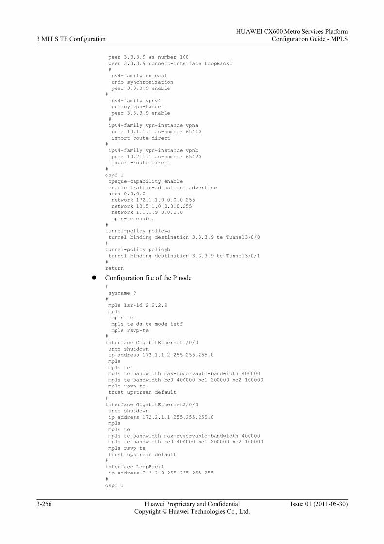
peer 3.3.3.9 as-number 100 peer 3.3.3.9 connect-interface LoopBack1 # ipv4-family unicast undo synchronization peer 3.3.3.9 enable# ipv4-family vpnv4 policy vpn-target peer 3.3.3.9 enable # ipv4-family vpn-instance vpna peer 10.1.1.1 as-number 65410 import-route direct# ipv4-family vpn-instance vpnb peer 10.2.1.1 as-number 65420 import-route direct#ospf 1 opaque-capability enable enable traffic-adjustment advertise area 0.0.0.0 network 172.1.1.0 0.0.0.255 network 10.5.1.0 0.0.0.255 network 1.1.1.9 0.0.0.0 mpls-te enable#tunnel-policy policya tunnel binding destination 3.3.3.9 te Tunnel3/0/0#tunnel-policy policyb tunnel binding destination 3.3.3.9 te Tunnel3/0/1#return
l Configuration file of the P node# sysname P# mpls lsr-id 2.2.2.9 mpls mpls te mpls te ds-te mode ietf mpls rsvp-te#interface GigabitEthernet1/0/0 undo shutdown ip address 172.1.1.2 255.255.255.0 mpls mpls te mpls te bandwidth max-reservable-bandwidth 400000 mpls te bandwidth bc0 400000 bc1 200000 bc2 100000 mpls rsvp-te trust upstream default#interface GigabitEthernet2/0/0 undo shutdown ip address 172.2.1.1 255.255.255.0 mpls mpls te mpls te bandwidth max-reservable-bandwidth 400000 mpls te bandwidth bc0 400000 bc1 200000 bc2 100000 mpls rsvp-te trust upstream default#interface LoopBack1 ip address 2.2.2.9 255.255.255.255#ospf 1
3 MPLS TE ConfigurationHUAWEI CX600 Metro Services Platform
Configuration Guide - MPLS
3-256 Huawei Proprietary and ConfidentialCopyright © Huawei Technologies Co., Ltd.
Issue 01 (2011-05-30)
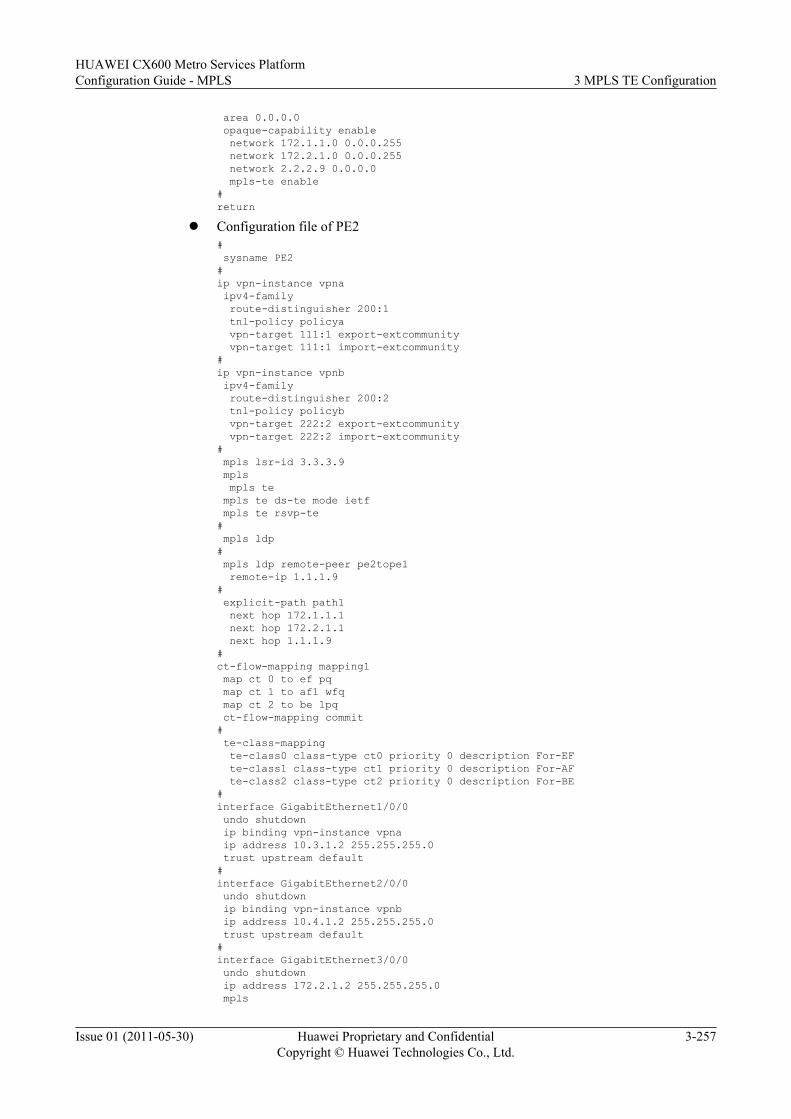
area 0.0.0.0 opaque-capability enable network 172.1.1.0 0.0.0.255 network 172.2.1.0 0.0.0.255 network 2.2.2.9 0.0.0.0 mpls-te enable#return
l Configuration file of PE2# sysname PE2#ip vpn-instance vpna ipv4-family route-distinguisher 200:1 tnl-policy policya vpn-target 111:1 export-extcommunity vpn-target 111:1 import-extcommunity#ip vpn-instance vpnb ipv4-family route-distinguisher 200:2 tnl-policy policyb vpn-target 222:2 export-extcommunity vpn-target 222:2 import-extcommunity# mpls lsr-id 3.3.3.9 mpls mpls te mpls te ds-te mode ietf mpls te rsvp-te# mpls ldp# mpls ldp remote-peer pe2tope1 remote-ip 1.1.1.9# explicit-path path1 next hop 172.1.1.1 next hop 172.2.1.1 next hop 1.1.1.9#ct-flow-mapping mapping1 map ct 0 to ef pq map ct 1 to af1 wfq map ct 2 to be lpq ct-flow-mapping commit# te-class-mapping te-class0 class-type ct0 priority 0 description For-EF te-class1 class-type ct1 priority 0 description For-AF te-class2 class-type ct2 priority 0 description For-BE#interface GigabitEthernet1/0/0 undo shutdown ip binding vpn-instance vpna ip address 10.3.1.2 255.255.255.0 trust upstream default#interface GigabitEthernet2/0/0 undo shutdown ip binding vpn-instance vpnb ip address 10.4.1.2 255.255.255.0 trust upstream default#interface GigabitEthernet3/0/0 undo shutdown ip address 172.2.1.2 255.255.255.0 mpls
HUAWEI CX600 Metro Services PlatformConfiguration Guide - MPLS 3 MPLS TE Configuration
Issue 01 (2011-05-30) Huawei Proprietary and ConfidentialCopyright © Huawei Technologies Co., Ltd.
3-257
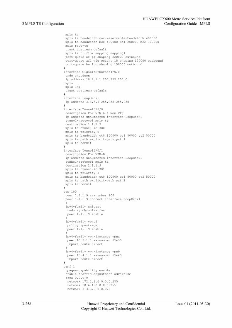
mpls te mpls te bandwidth max-reservable-bandwidth 400000 mpls te bandwidth bc0 400000 bc1 200000 bc2 100000 mpls rsvp-te trust upstream default mpls te ct-flow-mapping mapping1 port-queue ef pq shaping 220000 outbound port-queue af1 wfq weight 15 shaping 120000 outbound port-queue be lpq shaping 150000 outbound#interface GigabitEthernet4/0/0 undo shutdown ip address 10.6.1.1 255.255.255.0 mpls mpls ldp trust upstream default#interface LoopBack1 ip address 3.3.3.9 255.255.255.255#interface Tunnel3/0/0 description For VPN-A & Non-VPN ip address unnumbered interface LoopBack1 tunnel-protocol mpls te destination 1.1.1.9 mpls te tunnel-id 300 mpls te priority 0 mpls te bandwidth ct0 100000 ct1 50000 ct2 50000 mpls te path explicit-path path1 mpls te commit#interface Tunnel3/0/1 description For VPN-B ip address unnumbered interface LoopBack1 tunnel-protocol mpls te destination 1.1.1.9 mpls te tunnel-id 301 mpls te priority 0 mpls te bandwidth ct0 100000 ct1 50000 ct2 50000 mpls te path explicit-path path1 mpls te commit#bgp 100 peer 1.1.1.9 as-number 100 peer 1.1.1.9 connect-interface LoopBack1 # ipv4-family unicast undo synchronization peer 1.1.1.9 enable # ipv4-family vpnv4 policy vpn-target peer 1.1.1.9 enable # ipv4-family vpn-instance vpna peer 10.3.1.1 as-number 65430 import-route direct # ipv4-family vpn-instance vpnb peer 10.4.1.1 as-number 65440 import-route direct#ospf 1 opaque-capability enable enable traffic-adjustment advertise area 0.0.0.0 network 172.2.1.0 0.0.0.255 network 10.6.1.0 0.0.0.255 network 3.3.3.9 0.0.0.0
3 MPLS TE ConfigurationHUAWEI CX600 Metro Services Platform
Configuration Guide - MPLS
3-258 Huawei Proprietary and ConfidentialCopyright © Huawei Technologies Co., Ltd.
Issue 01 (2011-05-30)
mpls-te enable#tunnel-policy policya tunnel binding destination 1.1.1.9 te Tunnel3/0/0#tunnel-policy policyb tunnel binding destination 1.1.1.9 te Tunnel3/0/1#return
l Configuration file of PE3# sysname PE3# mpls lsr-id 4.4.4.9 mpls# mpls ldp#interface GigabitEthernet1/0/0 undo shutdown ip address 10.5.1.2 255.255.255.0 mpls mpls ldp#interface LoopBack1 ip address 4.4.4.9 255.255.255.255#ospf 1 area 0.0.0.0 network 10.5.1.0 0.0.0.255 network 4.4.4.9 0.0.0.0#return
l Configuration file of PE4# sysname PE4# mpls lsr-id 5.5.5.9 mpls# mpls ldp#interface GigabitEthernet1/0/0 undo shutdown ip address 10.6.1.2 255.255.255.0 mpls mpls ldp#interface LoopBack1 ip address 5.5.5.9 255.255.255.255#ospf 1 area 0.0.0.0 network 10.6.1.0 0.0.0.255 network 5.5.5.9 0.0.0.0#return
l Configuration file of CE1# sysname CE1#interface GigabitEthernet1/0/0 undo shutdown ip address 10.1.1.1 255.255.255.0#bgp 65410 peer 10.1.1.2 as-number 100
HUAWEI CX600 Metro Services PlatformConfiguration Guide - MPLS 3 MPLS TE Configuration
Issue 01 (2011-05-30) Huawei Proprietary and ConfidentialCopyright © Huawei Technologies Co., Ltd.
3-259
# ipv4-family unicast undo synchronization import-route direct peer 10.1.1.2 enable#return
l Configuration file of CE2# sysname CE2#interface GigabitEthernet1/0/0 undo shutdown ip address 10.2.1.1 255.255.255.0#bgp 65420 peer 10.2.1.2 as-number 100 # ipv4-family unicast undo synchronization import-route direct peer 10.2.1.2 enable#return
l Configuration file of CE3# sysname CE3#interface GigabitEthernet1/0/0 undo shutdown ip address 10.3.1.1 255.255.255.0#bgp 65430 peer 10.3.1.2 as-number 100 # ipv4-family unicast undo synchronization import-route direct peer 10.3.1.2 enable#return
l Configuration file of CE4# sysname CE4#interface GigabitEthernet1/0/0 undo shutdown ip address 10.4.1.1 255.255.255.0#bgp 65440 peer 10.4.1.2 as-number 100 # ipv4-family unicast undo synchronization import-route direct peer 10.4.1.2 enable#return
3.26.13 Example for Switching the Non-IETF Mode to the IETFMode
This section provides an example for switching the non-IETF mode to the IETF mode.
3 MPLS TE ConfigurationHUAWEI CX600 Metro Services Platform
Configuration Guide - MPLS
3-260 Huawei Proprietary and ConfidentialCopyright © Huawei Technologies Co., Ltd.
Issue 01 (2011-05-30)
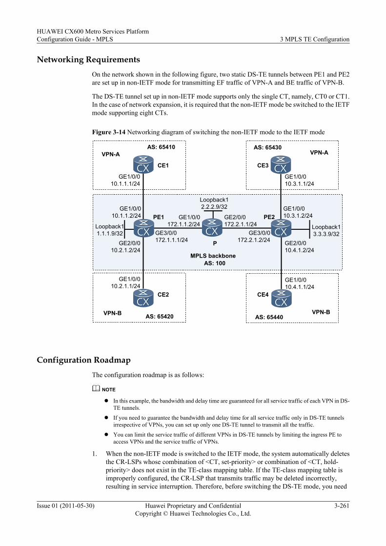
Networking Requirements
On the network shown in the following figure, two static DS-TE tunnels between PE1 and PE2are set up in non-IETF mode for transmitting EF traffic of VPN-A and BE traffic of VPN-B.
The DS-TE tunnel set up in non-IETF mode supports only the single CT, namely, CT0 or CT1.In the case of network expansion, it is required that the non-IETF mode be switched to the IETFmode supporting eight CTs.
Figure 3-14 Networking diagram of switching the non-IETF mode to the IETF mode
AS: 65440VPN-B
CE4
PE1
P
AS: 65430VPN-A
CE3
GE1/0/010.3.1.1/24
GE1/0/010.3.1.2/24
AS: 65420VPN-B
CE2
AS: 65410VPN-A
CE1
GE1/0/010.1.1.1/24
GE1/0/010.1.1.2/24
GE3/0/0172.1.1.1/24
GE2/0/0172.2.1.1/24
AS: 100
PE2Loopback11.1.1.9/32
Loopback13.3.3.9/32
GE1/0/010.4.1.1/24
GE1/0/010.2.1.1/24
GE2/0/010.4.1.2/24
GE2/0/010.2.1.2/24
GE1/0/0172.1.1.2/24
GE3/0/0172.2.1.2/24
MPLS backbone
Loopback12.2.2.9/32
Configuration Roadmap
The configuration roadmap is as follows:
NOTE
l In this example, the bandwidth and delay time are guaranteed for all service traffic of each VPN in DS-TE tunnels.
l If you need to guarantee the bandwidth and delay time for all service traffic only in DS-TE tunnelsirrespective of VPNs, you can set up only one DS-TE tunnel to transmit all the traffic.
l You can limit the service traffic of different VPNs in DS-TE tunnels by limiting the ingress PE toaccess VPNs and the service traffic of VPNs.
1. When the non-IETF mode is switched to the IETF mode, the system automatically deletesthe CR-LSPs whose combination of <CT, set-priority> or combination of <CT, hold-priority> does not exist in the TE-class mapping table. If the TE-class mapping table isimproperly configured, the CR-LSP that transmits traffic may be deleted incorrectly,resulting in service interruption. Therefore, before switching the DS-TE mode, you need
HUAWEI CX600 Metro Services PlatformConfiguration Guide - MPLS 3 MPLS TE Configuration
Issue 01 (2011-05-30) Huawei Proprietary and ConfidentialCopyright © Huawei Technologies Co., Ltd.
3-261
to check the CTs, setup priority, and holding priority of the ingress and transit CR-LSPs,and the configuration of TE-class mapping table.
2. For certain CR-LSPs, if the combination of the CT and setup priority or the combinationof the CT and holding priority does not exist in the TE-class mapping table, you need toconfigure or modify the TE-class mapping table.
3. Switch the DS-TE mode.4. Configure related DS-TE items or related services.
Data Preparation
None
Procedure
Step 1 Run the display current-configuration | include static-cr-lsp ingress and display current-configuration | include static-cr-lsp transit commands on PE1, P, and PE2, and you can viewthe CTs of the static ingress and transit CR-LSPs, and the TE-class mapping table.
NOTE
l For static CR-LSPs, both the setup priority and the holding priority are 0 and the two priorities neednot to be checked.
l For RSVP CR-LSPs, run the display current-configuration interface tunnel command, and you canview the configured mpls te bandwidth and mpls te priority commands, CTs, setup priority, andholding priority on each tunnel interface.
# Run the display current-configuration | include static-cr-lsp ingress and display current-configuration | include static-cr-lsp transit commands on the PE and P, and you can viewCTs, setup and holding priorities of the static ingress and transit CR-LSPs. Then, run the displaympls te ds-te te-class-mapping config command, and you can view the configuration of theTE-class mapping table.
# Take the display on PE1 as an example. The operation on other nodes is similar to that on PE1and therefore is not provided here.
<PE1> display current-configuration | include static-cr-lsp ingress static-cr-lsp ingress tunnel-interface Tunnel 3/0/0 destination 3.3.3.9 nexthop 172.1.1.2 out-label 100 bandwidth ct0 100000 static-cr-lsp ingress tunnel-interface tunnel 3/0/1 destination 3.3.3.9 nexthop 172.1.1.2 out-label 200 bandwidth ct1 200000<PE1> display current-configuration | include static-cr-lsp transit <PE1> display mpls te ds-te te-class-mapping config Info: Configure TE-Class first.
NOTE
The display current-configuration | include static-cr-lsp transit command output is null, indicating thatno static transit CR-LSP is set up on PE1.
The display mpls te ds-te te-class-mapping config command output shows "Info: Configure TE-Classfirst.", indicating that no TE-class mapping table is configured on PE1.
# The command output indicates that the static CR-LSPs of CT0 and CT1 are set up on PE1. Inaddition, because the setup and holding priorities of the static CR-LSPs are 0, the following TE-classes must exist in the TE-class mapping table:l <CT = CT0, Priority = 0>l <CT = CT1, Priority = 0>
Step 2 Configure TE-classes on PE1, P, and PE2.
3 MPLS TE ConfigurationHUAWEI CX600 Metro Services Platform
Configuration Guide - MPLS
3-262 Huawei Proprietary and ConfidentialCopyright © Huawei Technologies Co., Ltd.
Issue 01 (2011-05-30)
In this example, the TE-classes of <CT = CT0, Priority = 0> and <CT = CT1, Priority = 0> needto be configured. Because the two TE-classes already exist in the default TE-class mapping table,no other TE-class mapping table needs to be configured in this example. After the non-IETFmode is switched to the IETF mode, the system uses the default TE-class mapping table.
NOTEFor information about the default TE-class mapping table, see Table 3-2.
Step 3 Switch the DS-TE modes on PE1, P, and PE2.
# Configure PE1.
[PE1] mpls[PE1-mpls] mpls te ds-te mode ietf[PE1-mpls] quit
# Configure P.
[P] mpls[P-mpls] mpls te ds-te mode ietf[P-mpls] quit
# Configure PE2.
[PE2] mpls[PE2-mpls] mpls te ds-te mode ietf[PE2-mpls] quit
NOTE
After the non-IETF mode is switched to the IETF mode, the bandwidth constraints model remainsunchanged and does not need to be configured again.
In addition, related configurations of DS-TE and services accesses are required according to the service.The configurations are not provided in this example.
----End
Configuration Filesl Configuration file of PE1
# sysname PE1#ip vpn-instance vpna ipv4-family route-distinguisher 100:1 tnl-policy policya vpn-target 111:1 export-extcommunity vpn-target 111:1 import-extcommunity#ip vpn-instance vpnb ipv4-family route-distinguisher 100:2 tnl-policy policyb vpn-target 222:2 export-extcommunity vpn-target 222:2 import-extcommunity# mpls lsr-id 1.1.1.9 mpls mpls te ds-te mode ietf mpls te ds-te bcm mam#ct-flow-mapping mapping1 map ct 0 to ef pq map ct 1 to be lpq ct-flow-mapping commit
HUAWEI CX600 Metro Services PlatformConfiguration Guide - MPLS 3 MPLS TE Configuration
Issue 01 (2011-05-30) Huawei Proprietary and ConfidentialCopyright © Huawei Technologies Co., Ltd.
3-263
#interface GigabitEthernet1/0/0 undo shutdown ip binding vpn-instance vpna ip address 10.1.1.2 255.255.255.0 trust upstream default#interface GigabitEthernet2/0/0 undo shutdown ip binding vpn-instance vpnb ip address 10.2.1.2 255.255.255.0 trust upstream default#interface GigabitEthernet3/0/0 undo shutdown ip address 172.1.1.1 255.255.255.0 mpls mpls te mpls te bandwidth max-reservable-bandwidth 300000 mpls te bandwidth bc0 100000 bc1 200000 trust upstream default mpls te ct-flow-mapping mapping1 mpls te ct-bandwidth unshared#interface LoopBack1 ip address 1.1.1.9 255.255.255.255#interface Tunnel3/0/0 description For VPN-A_EF ip address unnumbered interface LoopBack1 tunnel-protocol mpls te destination 3.3.3.9 mpls te tunnel-id 300 mpls te signal-protocol cr-static mpls te commit#interface Tunnel3/0/1 description For VPN-B_BE ip address unnumbered interface LoopBack1 tunnel-protocol mpls te destination 3.3.3.9 mpls te tunnel-id 301 mpls te signal-protocol cr-static mpls te commit#bgp 100 peer 3.3.3.9 as-number 100 peer 3.3.3.9 connect-interface LoopBack1 # ipv4-family unicast undo synchronization peer 3.3.3.9 enable# ipv4-family vpnv4 policy vpn-target peer 3.3.3.9 enable # ipv4-family vpn-instance vpna peer 10.1.1.1 as-number 65410 import-route direct# ipv4-family vpn-instance vpnb peer 10.2.1.1 as-number 65420 import-route direct#ospf 1 opaque-capability enable area 0.0.0.0 network 172.1.1.0 0.0.0.255
3 MPLS TE ConfigurationHUAWEI CX600 Metro Services Platform
Configuration Guide - MPLS
3-264 Huawei Proprietary and ConfidentialCopyright © Huawei Technologies Co., Ltd.
Issue 01 (2011-05-30)

network 1.1.1.9 0.0.0.0 mpls-te enable# static-cr-lsp ingress tunnel-interface Tunnel 3/0/0 destination 3.3.3.9 nexthop 172.1.1.2 out-label 100 bandwidth ct0 100000 static-cr-lsp ingress tunnel-interface tunnel 3/0/1 destination 3.3.3.9 nexthop 172.1.1.2 out-label 200 bandwidth ct1 200000 static-cr-lsp egress VPN-A_EF incoming-interface gigabitethernet 3/0/0 in-label 101 static-cr-lsp egress VPN-B_BE incoming-interface gigabitethernet 3/0/0 in-label 201#tunnel-policy policya tunnel binding destination 3.3.3.9 te Tunnel3/0/0#tunnel-policy policyb tunnel binding destination 3.3.3.9 te Tunnel3/0/1#return
l Configuration file of the P node# sysname P# mpls lsr-id 2.2.2.9 mpls mpls te mpls te ds-te mode ietf mpls te ds-te bcm mam#interface GigabitEthernet1/0/0 undo shutdown ip address 172.1.1.2 255.255.255.0 mpls mpls te mpls te bandwidth max-reservable-bandwidth 300000 mpls te bandwidth bc0 100000 bc1 200000 trust upstream default#interface GigabitEthernet2/0/0 undo shutdown ip address 172.2.1.1 255.255.255.0 mpls mpls te mpls te bandwidth max-reservable-bandwidth 300000 mpls te bandwidth bc0 100000 bc1 200000 trust upstream default#interface LoopBack1 ip address 2.2.2.9 255.255.255.255#ospf 1 opaque-capability enable area 0.0.0.0 network 172.1.1.0 0.0.0.255 network 172.2.1.0 0.0.0.255 network 2.2.2.9 0.0.0.0 mpls-te enable# static-cr-lsp transit VPN-A_EF-1to2 incoming-interface gigabitethernet1/0/0 in-label 100 nexthop 172.2.1.2 out-label 100 bandwidth ct0 100000 static-cr-lsp transit VPN-B_BE-1to2 incoming-interface gigabitethernet1/0/0 in-label 200 nexthop 172.2.1.2 out-label 200 bandwidth ct1 200000 static-cr-lsp transit VPN-A_EF-2to1 incoming-interface gigabitethernet2/0/0 in-label 101 nexthop 172.1.1.1 out-label 101 bandwidth ct0 100000 static-cr-lsp transit VPN-B_BE-2to1 incoming-interface gigabitethernet2/0/0 in-label 201 nexthop 172.1.1.1 out-label 201 bandwidth ct1 200000#return
HUAWEI CX600 Metro Services PlatformConfiguration Guide - MPLS 3 MPLS TE Configuration
Issue 01 (2011-05-30) Huawei Proprietary and ConfidentialCopyright © Huawei Technologies Co., Ltd.
3-265
l Configuration file of PE2# sysname PE2#ip vpn-instance vpna ipv4-family route-distinguisher 200:1 tnl-policy policya vpn-target 111:1 export-extcommunity vpn-target 111:1 import-extcommunity#ip vpn-instance vpnb ipv4-family route-distinguisher 200:2 tnl-policy policyb vpn-target 222:2 export-extcommunity vpn-target 222:2 import-extcommunity# mpls lsr-id 3.3.3.9 mpls mpls te mpls te ds-te mode ietf mpls te ds-te bcm mam#ct-flow-mapping mapping1 map ct 0 to ef pq map ct 1 to be lpq ct-flow-mapping commit#interface GigabitEthernet1/0/0 undo shutdown ip binding vpn-instance vpna ip address 10.3.1.2 255.255.255.0 trust upstream default#interface GigabitEthernet2/0/0 undo shutdown ip binding vpn-instance vpnb ip address 10.4.1.2 255.255.255.0 trust upstream default#interface GigabitEthernet3/0/0 undo shutdown ip address 172.2.1.2 255.255.255.0 mpls mpls te mpls te bandwidth max-reservable-bandwidth 300000 mpls te bandwidth bc0 100000 bc1 200000 trust upstream default mpls te ct-flow-mapping mapping1 mpls te ct-bandwidth unshared#interface LoopBack1 ip address 3.3.3.9 255.255.255.255#interface Tunnel3/0/0 description For VPN-A_EF ip address unnumbered interface LoopBack1 tunnel-protocol mpls te destination 1.1.1.9 mpls te tunnel-id 300 mpls te signal-protocol cr-static mpls te commit#interface Tunnel3/0/1 description For VPN-B_BE ip address unnumbered interface LoopBack1 tunnel-protocol mpls te destination 1.1.1.9
3 MPLS TE ConfigurationHUAWEI CX600 Metro Services Platform
Configuration Guide - MPLS
3-266 Huawei Proprietary and ConfidentialCopyright © Huawei Technologies Co., Ltd.
Issue 01 (2011-05-30)
mpls te tunnel-id 301 mpls te signal-protocol cr-static mpls te commit#bgp 100 peer 1.1.1.9 as-number 100 peer 1.1.1.9 connect-interface LoopBack1 # ipv4-family unicast undo synchronization peer 1.1.1.9 enable # ipv4-family vpnv4 policy vpn-target peer 1.1.1.9 enable # ipv4-family vpn-instance vpna peer 10.3.1.1 as-number 65430 import-route direct # ipv4-family vpn-instance vpnb peer 10.4.1.1 as-number 65440 import-route direct#ospf 1 opaque-capability enable area 0.0.0.0 network 172.2.1.0 0.0.0.255 network 3.3.3.9 0.0.0.0 mpls-te enable# static-cr-lsp egress VPN-A_EF incoming-interface gigabitethernet 3/0/0 in-label 100 static-cr-lsp egress VPN-B_BE incoming-interface gigabitethernet 3/0/0 in-label 200 static-cr-lsp ingress tunnel-interface tunnel 3/0/0 destination 1.1.1.9 nexthop 172.2.1.1 out-label 101 bandwidth ct0 100000 static-cr-lsp ingress tunnel-interface tunnel 3/0/1 destination 1.1.1.9 nexthop 172.2.1.1 out-label 201 bandwidth ct1 200000#tunnel-policy policya tunnel binding destination 1.1.1.9 te Tunnel3/0/0#tunnel-policy policyb tunnel binding destination 1.1.1.9 te Tunnel3/0/1#return
3.26.14 Example for Configuring MPLS TE FRRThis section provides an example for implementing link protection by using TE FRR.
Networking RequirementsOn the network shown in Figure 3-15, the primary LSP is along the path LSR A --> LSR B --> LSR C --> LSR D, and the link from LSR B to LSR C requires a link protection by using FRR.
A bypass LSP is set up over the path LSR B --> LSR E --> LSR C. LSR B is a PLR, and LSRC is an MP.
An explicit path is used to establish the MPLS TE primary and the bypass tunnels. The RSVP-TE signaling protocol is adopted.
HUAWEI CX600 Metro Services PlatformConfiguration Guide - MPLS 3 MPLS TE Configuration
Issue 01 (2011-05-30) Huawei Proprietary and ConfidentialCopyright © Huawei Technologies Co., Ltd.
3-267
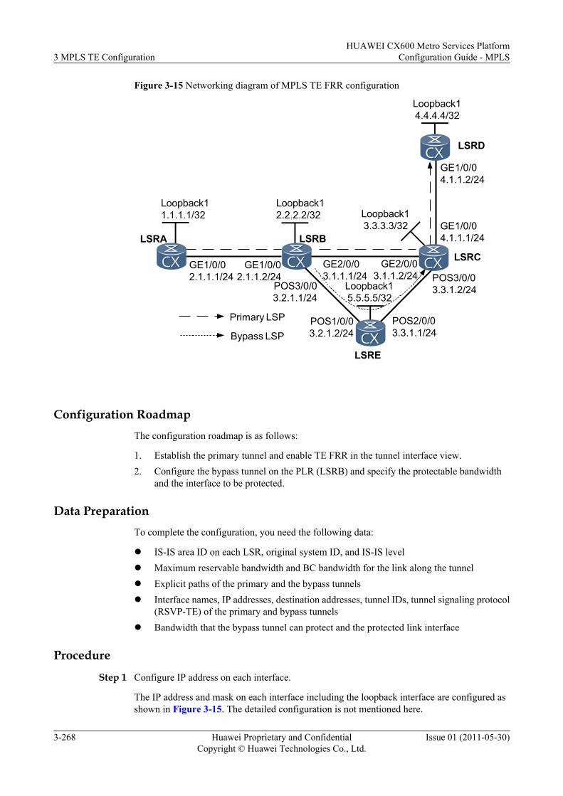
Figure 3-15 Networking diagram of MPLS TE FRR configuration
Loopback15.5.5.5/32
Loopback12.2.2.2/32
GE1/0/02.1.1.1/24
GE1/0/02.1.1.2/24
LSRA
GE2/0/03.1.1.1/24
GE2/0/03.1.1.2/24
LSRB
LSRC
LSRE
POS3/0/03.2.1.1/24
POS1/0/03.2.1.2/24
POS2/0/03.3.1.1/24
POS3/0/03.3.1.2/24
Primary LSP
Bypass LSP
LSRD
GE1/0/04.1.1.1/24
GE1/0/04.1.1.2/24
Loopback11.1.1.1/32 Loopback1
3.3.3.3/32
Loopback14.4.4.4/32
Configuration RoadmapThe configuration roadmap is as follows:
1. Establish the primary tunnel and enable TE FRR in the tunnel interface view.2. Configure the bypass tunnel on the PLR (LSRB) and specify the protectable bandwidth
and the interface to be protected.
Data PreparationTo complete the configuration, you need the following data:
l IS-IS area ID on each LSR, original system ID, and IS-IS levell Maximum reservable bandwidth and BC bandwidth for the link along the tunnell Explicit paths of the primary and the bypass tunnelsl Interface names, IP addresses, destination addresses, tunnel IDs, tunnel signaling protocol
(RSVP-TE) of the primary and bypass tunnelsl Bandwidth that the bypass tunnel can protect and the protected link interface
Procedure
Step 1 Configure IP address on each interface.
The IP address and mask on each interface including the loopback interface are configured asshown in Figure 3-15. The detailed configuration is not mentioned here.
3 MPLS TE ConfigurationHUAWEI CX600 Metro Services Platform
Configuration Guide - MPLS
3-268 Huawei Proprietary and ConfidentialCopyright © Huawei Technologies Co., Ltd.
Issue 01 (2011-05-30)
Step 2 Configure an IGP.
The IS-IS protocol is configured on all LSRs to advertise routes of LSR IDs. The detailedconfiguration is not provided here.
After the configuration, run the display ip routing-table command on each LSR and you canview that the LSRs learned routes from each other.
Step 3 Configure the basic MPLS functions and enable MPLS TE, CSPF, RSVP-TE, and IS-IS TE.
# Configure LSR A.
[LSRA] mpls lsr-id 1.1.1.1[LSRA] mpls[LSRA-mpls] mpls te[LSRA-mpls] mpls rsvp-te[LSRA-mpls] mpls te cspf[LSRA-mpls] quit[LSRA] interface gigabitethernet 1/0/0[LSRA-GigabitEthernet1/0/0] mpls[LSRA-GigabitEthernet1/0/0] mpls te[LSRA-GigabitEthernet1/0/0] mpls rsvp-te[LSRA-GigabitEthernet1/0/0] quit[LSRA] isis[LSRA-isis-1] cost-style wide[LSRA-isis-1] traffic-eng level-2
NOTE
The configurations of LSR B, LSR C, LSR D, and LSR E are similar to those of LSR A and LSR B, andare not provided here.Only LSR A and LSR B need to be enabled CSPF.
Step 4 Configuring the MPLS TE attributes of the links.
# Configure the maximum reservable link bandwidth as 100 Mbit/s and BC bandwidth as 100Mbit/s on LSR A, LSR B, LSR C, LSR D, and LSR E.
# Configure LSR A.
[LSRA] interface gigabitethernet 1/0/0[LSRA-GigabitEthernet1/0/0] mpls te bandwidth max-reservable-bandwidth 100000[LSRA-GigabitEthernet1/0/0] mpls te bandwidth bc0 100000[LSRA-GigabitEthernet1/0/0] quit
# Configure LSR B.
[LSRB] interface gigabitethernet 2/0/0[LSRB-GigabitEthernet2/0/0] mpls te bandwidth max-reservable-bandwidth 100000[LSRB-GigabitEthernet2/0/0] mpls te bandwidth bc0 100000[LSRB-GigabitEthernet2/0/0] quit[LSRB] interface pos 3/0/0[LSRB-Pos3/0/0] mpls te bandwidth max-reservable-bandwidth 100000[LSRB-Pos3/0/0] mpls te bandwidth bc0 100000[LSRB-Pos3/0/0] quit
# Configure LSR C.
[LSRC] interface gigabitethernet 1/0/0[LSRC-GigabitEthernet1/0/0] mpls te bandwidth max-reservable-bandwidth 100000[LSRC-GigabitEthernet1/0/0] mpls te bandwidth bc0 100000[LSRC-GigabitEthernet1/0/0] quit
# Configure LSR E.
[LSRE] interface pos 2/0/0[LSRE-Pos2/0/0] mpls te bandwidth max-reservable-bandwidth 100000[LSRE-Pos2/0/0] mpls te bandwidth bc0 100000
HUAWEI CX600 Metro Services PlatformConfiguration Guide - MPLS 3 MPLS TE Configuration
Issue 01 (2011-05-30) Huawei Proprietary and ConfidentialCopyright © Huawei Technologies Co., Ltd.
3-269
[LSRE-Pos2/0/0] quit
Step 5 Establish an MPLS TE tunnel as the primary LSP on LSR A.
# Configure the explicit path for the primary LSP.
[LSRA] explicit-path pri-path[LSRA-explicit-path-pri-path] next hop 2.1.1.2[LSRA-explicit-path-pri-path] next hop 3.1.1.2[LSRA-explicit-path-pri-path] next hop 4.1.1.2[LSRA-explicit-path-pri-path] next hop 4.4.4.4[LSRA-explicit-path-pri-path] quit
# Configure the MPLS TE tunnel as the primary LSP.
[LSRA] interface tunnel 1/0/0[LSRA-Tunnel1/0/0] ip address unnumbered interface loopback 1[LSRA-Tunnel1/0/0] tunnel-protocol mpls te[LSRA-Tunnel1/0/0] destination 4.4.4.4[LSRA-Tunnel1/0/0] mpls te tunnel-id 100[LSRA-Tunnel1/0/0] mpls te signal-protocol rsvp-te[LSRA-Tunnel1/0/0] mpls te bandwidth ct0 50000[LSRA-Tunnel1/0/0] mpls te path explicit-path pri-path
# Enable FRR.
[LSRA-Tunnel1/0/0] mpls te fast-reroute[LSRA-Tunnel1/0/0] mpls te commit[LSRA-Tunnel1/0/0] quit
After the configuration, run the display interface tunnel command on LSR A. The status ofTunnel 1/0/0 is Up.
[LSRA] display interface tunnel 1/0/0Tunnel1/0/0 current state : UPLine protocol current state : UPLast up time: 2009-01-12, 09:35:10Description : Tunnel1/0/0 Interface, Route Port...
Run the display mpls te tunnel verbose command on LSR A. You can view information aboutthe tunnel interface.
[LSRA] display mpls te tunnel verbose No : 1 Tunnel-Name : Tunnel1/0/0 TunnelIndex : 0 LSP Index : 2048 Session ID : 100 LSP ID : 1 Lsr Role : Ingress Lsp Type : Primary Ingress LSR ID : 1.1.1.1 Egress LSR ID : 4.4.4.4 In-Interface : - Out-Interface : GE1/0/0 Sign-Protocol : RSVP TE Resv Style : SE IncludeAnyAff : 0x0 ExcludeAnyAff : 0x0 IncludeAllAff : 0x0 LspConstraint : - ER-Hop Table Index : 0 AR-Hop Table Index: 0 C-Hop Table Index : 0 PrevTunnelIndexInSession: - NextTunnelIndexInSession: - PSB Handle : 1081 Created Time : 2010/07/01 15:02:57 UTC-08:00 -------------------------------- DS-TE Information -------------------------------- Bandwidth Reserved Flag : Reserved CT0 Bandwidth(Kbit/sec) : 50000 CT1 Bandwidth(Kbit/sec): 0 CT2 Bandwidth(Kbit/sec) : 0 CT3 Bandwidth(Kbit/sec): 0 CT4 Bandwidth(Kbit/sec) : 0 CT5 Bandwidth(Kbit/sec): 0
3 MPLS TE ConfigurationHUAWEI CX600 Metro Services Platform
Configuration Guide - MPLS
3-270 Huawei Proprietary and ConfidentialCopyright © Huawei Technologies Co., Ltd.
Issue 01 (2011-05-30)
CT6 Bandwidth(Kbit/sec) : 0 CT7 Bandwidth(Kbit/sec): 0 Setup-Priority : 7 Hold-Priority : 7 -------------------------------- FRR Information -------------------------------- Primary LSP Info TE Attribute Flag : 0x63 Protected Flag : 0x0 Bypass In Use : Not Exists Bypass Tunnel Id : - BypassTunnel : - Bypass Lsp ID : - FrrNextHop : - ReferAutoBypassHandle : - FrrPrevTunnelTableIndex : - FrrNextTunnelTableIndex: - Bypass Attribute(Not configured) Setup Priority : - Hold Priority : - HopLimit : - Bandwidth : - IncludeAnyGroup : - ExcludeAnyGroup : - IncludeAllGroup : - Bypass Unbound Bandwidth Info(Kbit/sec) CT0 Unbound Bandwidth : - CT1 Unbound Bandwidth: - CT2 Unbound Bandwidth : - CT3 Unbound Bandwidth: - CT4 Unbound Bandwidth : - CT5 Unbound Bandwidth: - CT6 Unbound Bandwidth : - CT7 Unbound Bandwidth: - -------------------------------- BFD Information -------------------------------- NextSessionTunnelIndex : - PrevSessionTunnelIndex: - NextLspId : - PrevLspId : -
Step 6 Configure the bypass tunnel on LSR B that functions as PLR.
# Configure the explicit path of the bypass LSP.
[LSRB] explicit-path by-path[LSRB-explicit-path-by-path] next hop 3.2.1.2[LSRB-explicit-path-by-path] next hop 3.3.1.2[LSRB-explicit-path-by-path] next hop 3.3.3.3[LSRB-explicit-path-by-path] quit
# Configure the bypass tunnel.
[LSRB] interface tunnel 3/0/0[LSRB-Tunnel3/0/0] ip address unnumbered interface loopback 1[LSRB-Tunnel3/0/0] tunnel-protocol mpls te[LSRB-Tunnel3/0/0] destination 3.3.3.3[LSRB-Tunnel3/0/0] mpls te tunnel-id 300[LSRB-Tunnel3/0/0] mpls te signal-protocol rsvp-te[LSRB-Tunnel3/0/0] mpls te path explicit-path by-path[LSRB-Tunnel3/0/0] mpls te bandwidth ct0 100000
# Configure bandwidth that can be protected by the bypass tunnel.
[LSRB-Tunnel3/0/0] mpls te bypass-tunnel
# Bind the bypass tunnel to the protected interface.
[LSRB-Tunnel3/0/0] mpls te protected-interface gigabitethernet 2/0/0[LSRB-Tunnel3/0/0] mpls te commit[LSRB-Tunnel3/0/0] quit
After the configuration, run the display interface tunnel command on LSR B. You can viewthat the status of the Tunnel 3/0/0 interface is Up.
Run the display mpls lsp command on all LSRs to check LSP entries. You can view that LSPspass through LSR B and LSR C.
[LSRA] display mpls lsp------------------------------------------------------------------ LSP Information: RSVP LSP
HUAWEI CX600 Metro Services PlatformConfiguration Guide - MPLS 3 MPLS TE Configuration
Issue 01 (2011-05-30) Huawei Proprietary and ConfidentialCopyright © Huawei Technologies Co., Ltd.
3-271
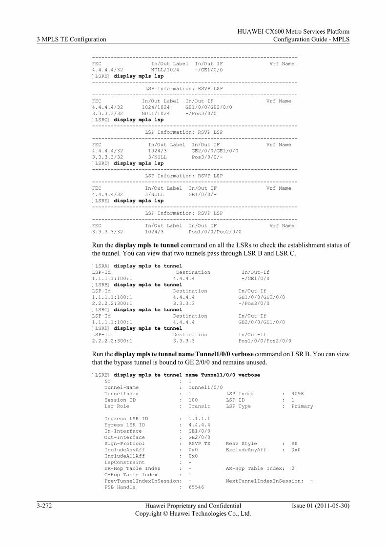
------------------------------------------------------------------FEC In/Out Label In/Out IF Vrf Name4.4.4.4/32 NULL/1024 -/GE1/0/0[LSRB] display mpls lsp------------------------------------------------------------------ LSP Information: RSVP LSP------------------------------------------------------------------FEC In/Out Label In/Out IF Vrf Name4.4.4.4/32 1024/1024 GE1/0/0/GE2/0/03.3.3.3/32 NULL/1024 -/Pos3/0/0[LSRC] display mpls lsp------------------------------------------------------------------ LSP Information: RSVP LSP------------------------------------------------------------------FEC In/Out Label In/Out IF Vrf Name4.4.4.4/32 1024/3 GE2/0/0/GE1/0/03.3.3.3/32 3/NULL Pos3/0/0/-[LSRD] display mpls lsp------------------------------------------------------------------ LSP Information: RSVP LSP------------------------------------------------------------------FEC In/Out Label In/Out IF Vrf Name4.4.4.4/32 3/NULL GE1/0/0/- [LSRE] display mpls lsp------------------------------------------------------------------ LSP Information: RSVP LSP------------------------------------------------------------------FEC In/Out Label In/Out IF Vrf Name3.3.3.3/32 1024/3 Pos1/0/0/Pos2/0/0
Run the display mpls te tunnel command on all the LSRs to check the establishment status ofthe tunnel. You can view that two tunnels pass through LSR B and LSR C.
[LSRA] display mpls te tunnelLSP-Id Destination In/Out-If1.1.1.1:100:1 4.4.4.4 -/GE1/0/0[LSRB] display mpls te tunnelLSP-Id Destination In/Out-If1.1.1.1:100:1 4.4.4.4 GE1/0/0/GE2/0/02.2.2.2:300:1 3.3.3.3 -/Pos3/0/0[LSRC] display mpls te tunnelLSP-Id Destination In/Out-If1.1.1.1:100:1 4.4.4.4 GE2/0/0/GE1/0/0[LSRE] display mpls te tunnelLSP-Id Destination In/Out-If2.2.2.2:300:1 3.3.3.3 Pos1/0/0/Pos2/0/0
Run the display mpls te tunnel name Tunnel1/0/0 verbose command on LSR B. You can viewthat the bypass tunnel is bound to GE 2/0/0 and remains unused.
[LSRB] display mpls te tunnel name Tunnel1/0/0 verbose No : 1 Tunnel-Name : Tunnel1/0/0 TunnelIndex : 1 LSP Index : 4098 Session ID : 100 LSP ID : 1 Lsr Role : Transit LSP Type : Primary
Ingress LSR ID : 1.1.1.1 Egress LSR ID : 4.4.4.4 In-Interface : GE1/0/0 Out-Interface : GE2/0/0 Sign-Protocol : RSVP TE Resv Style : SE IncludeAnyAff : 0x0 ExcludeAnyAff : 0x0 IncludeAllAff : 0x0 LspConstraint : - ER-Hop Table Index : - AR-Hop Table Index: 2 C-Hop Table Index : 1 PrevTunnelIndexInSession: - NextTunnelIndexInSession: - PSB Handle : 65546
3 MPLS TE ConfigurationHUAWEI CX600 Metro Services Platform
Configuration Guide - MPLS
3-272 Huawei Proprietary and ConfidentialCopyright © Huawei Technologies Co., Ltd.
Issue 01 (2011-05-30)
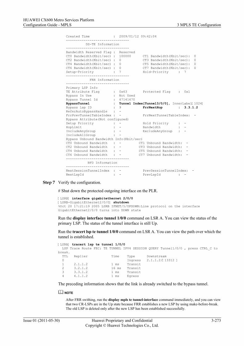
Created Time : 2009/01/12 09:42:04 -------------------------------- DS-TE Information -------------------------------- Bandwidth Reserved Flag : Reserved CT0 Bandwidth(Kbit/sec) : 100000 CT1 Bandwidth(Kbit/sec): 0 CT2 Bandwidth(Kbit/sec) : 0 CT3 Bandwidth(Kbit/sec): 0 CT4 Bandwidth(Kbit/sec) : 0 CT5 Bandwidth(Kbit/sec): 0 CT6 Bandwidth(Kbit/sec) : 0 CT7 Bandwidth(Kbit/sec): 0 Setup-Priority : 7 Hold-Priority : 7 -------------------------------- FRR Information -------------------------------- Primary LSP Info TE Attribute Flag : 0x63 Protected Flag : 0x1 Bypass In Use : Not Used Bypass Tunnel Id : 67141670 BypassTunnel : Tunnel Index[Tunnel3/0/0], InnerLabel[1024] Bypass Lsp ID : 9 FrrNextHop : 3.3.1.2 ReferAutoBypassHandle : - FrrPrevTunnelTableIndex : - FrrNextTunnelTableIndex: - Bypass Attribute(Not configured) Setup Priority : - Hold Priority : - HopLimit : - Bandwidth : - IncludeAnyGroup : - ExcludeAnyGroup : - IncludeAllGroup : - Bypass Unbound Bandwidth Info(Kbit/sec) CT0 Unbound Bandwidth : - CT1 Unbound Bandwidth: - CT2 Unbound Bandwidth : - CT3 Unbound Bandwidth: - CT4 Unbound Bandwidth : - CT5 Unbound Bandwidth: - CT6 Unbound Bandwidth : - CT7 Unbound Bandwidth: - -------------------------------- BFD Information -------------------------------- NextSessionTunnelIndex : - PrevSessionTunnelIndex: - NextLspId : - PrevLspId : -
Step 7 Verify the configuration.
# Shut down the protected outgoing interface on the PLR.
[LSRB] interface gigabitethernet 2/0/0[LSRB-GigabitEthernet2/0/0] shutdown%Oct 20 17:21:19 2005 LSRB IFNET/5/UPDOWN:Line protocol on the interface GigabitEthernet2/0/0 turns into DOWN state
Run the display interface tunnel 1/0/0 command on LSR A. You can view the status of theprimary LSP. The status of the tunnel interface is still Up.
Run the tracert lsp te tunnel 1/0/0 command on LSR A. You can view the path over which thetunnel is established.
[LSRA] tracert lsp te tunnel 1/0/0 LSP Trace Route FEC: TE TUNNEL IPV4 SESSION QUERY Tunnel1/0/0 , press CTRL_C to break. TTL Replier Time Type Downstream 0 Ingress 2.1.1.2/[13312 ] 1 2.1.1.2 1 ms Transit 2 3.2.1.2 16 ms Transit 3 3.3.1.2 1 ms Transit 4 4.1.1.2 1 ms Egress
The preceding information shows that the link is already switched to the bypass tunnel.
NOTE
After FRR swithing, run the display mpls te tunnel-interface command immediately, and you can viewthat two CR-LSPs are in the Up state because FRR establishes a new LSP by using make-before-break.The old LSP is deleted only after the new LSP has been established successfully.
HUAWEI CX600 Metro Services PlatformConfiguration Guide - MPLS 3 MPLS TE Configuration
Issue 01 (2011-05-30) Huawei Proprietary and ConfidentialCopyright © Huawei Technologies Co., Ltd.
3-273
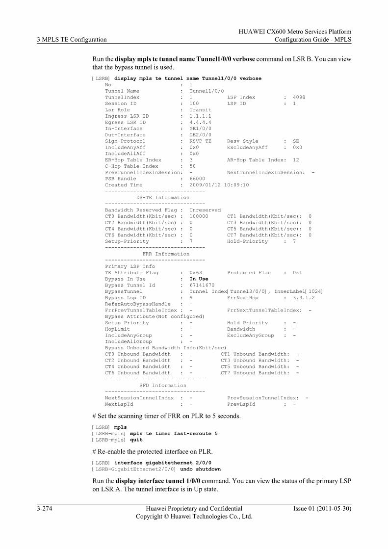
Run the display mpls te tunnel name Tunnel1/0/0 verbose command on LSR B. You can viewthat the bypass tunnel is used.[LSRB] display mpls te tunnel name Tunnel1/0/0 verbose No : 1 Tunnel-Name : Tunnel1/0/0 TunnelIndex : 1 LSP Index : 4098 Session ID : 100 LSP ID : 1 Lsr Role : Transit Ingress LSR ID : 1.1.1.1 Egress LSR ID : 4.4.4.4 In-Interface : GE1/0/0 Out-Interface : GE2/0/0 Sign-Protocol : RSVP TE Resv Style : SE IncludeAnyAff : 0x0 ExcludeAnyAff : 0x0 IncludeAllAff : 0x0 ER-Hop Table Index : 3 AR-Hop Table Index: 12 C-Hop Table Index : 50 PrevTunnelIndexInSession: - NextTunnelIndexInSession: - PSB Handle : 66000 Created Time : 2009/01/12 10:09:10 -------------------------------- DS-TE Information -------------------------------- Bandwidth Reserved Flag : Unreserved CT0 Bandwidth(Kbit/sec) : 100000 CT1 Bandwidth(Kbit/sec): 0 CT2 Bandwidth(Kbit/sec) : 0 CT3 Bandwidth(Kbit/sec): 0 CT4 Bandwidth(Kbit/sec) : 0 CT5 Bandwidth(Kbit/sec): 0 CT6 Bandwidth(Kbit/sec) : 0 CT7 Bandwidth(Kbit/sec): 0 Setup-Priority : 7 Hold-Priority : 7 -------------------------------- FRR Information -------------------------------- Primary LSP Info TE Attribute Flag : 0x63 Protected Flag : 0x1 Bypass In Use : In Use Bypass Tunnel Id : 67141670 BypassTunnel : Tunnel Index[Tunnel3/0/0], InnerLabel[1024] Bypass Lsp ID : 9 FrrNextHop : 3.3.1.2 ReferAutoBypassHandle : - FrrPrevTunnelTableIndex : - FrrNextTunnelTableIndex: - Bypass Attribute(Not configured) Setup Priority : - Hold Priority : - HopLimit : - Bandwidth : - IncludeAnyGroup : - ExcludeAnyGroup : - IncludeAllGroup : - Bypass Unbound Bandwidth Info(Kbit/sec) CT0 Unbound Bandwidth : - CT1 Unbound Bandwidth: - CT2 Unbound Bandwidth : - CT3 Unbound Bandwidth: - CT4 Unbound Bandwidth : - CT5 Unbound Bandwidth: - CT6 Unbound Bandwidth : - CT7 Unbound Bandwidth: - -------------------------------- BFD Information -------------------------------- NextSessionTunnelIndex : - PrevSessionTunnelIndex: - NextLspId : - PrevLspId : -
# Set the scanning timer of FRR on PLR to 5 seconds.[LSRB] mpls[LSRB-mpls] mpls te timer fast-reroute 5[LSRB-mpls] quit
# Re-enable the protected interface on PLR.[LSRB] interface gigabitethernet 2/0/0[LSRB-GigabitEthernet2/0/0] undo shutdown
Run the display interface tunnel 1/0/0 command. You can view the status of the primary LSPon LSR A. The tunnel interface is in Up state.
3 MPLS TE ConfigurationHUAWEI CX600 Metro Services Platform
Configuration Guide - MPLS
3-274 Huawei Proprietary and ConfidentialCopyright © Huawei Technologies Co., Ltd.
Issue 01 (2011-05-30)
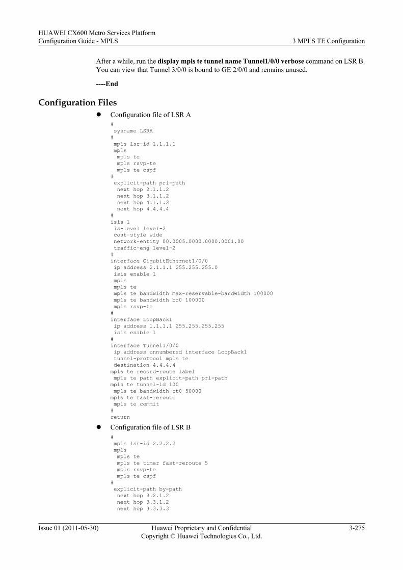
After a while, run the display mpls te tunnel name Tunnel1/0/0 verbose command on LSR B.You can view that Tunnel 3/0/0 is bound to GE 2/0/0 and remains unused.
----End
Configuration Filesl Configuration file of LSR A
# sysname LSRA# mpls lsr-id 1.1.1.1 mpls mpls te mpls rsvp-te mpls te cspf# explicit-path pri-path next hop 2.1.1.2 next hop 3.1.1.2 next hop 4.1.1.2 next hop 4.4.4.4#isis 1 is-level level-2 cost-style wide network-entity 00.0005.0000.0000.0001.00 traffic-eng level-2#interface GigabitEthernet1/0/0 ip address 2.1.1.1 255.255.255.0 isis enable 1 mpls mpls te mpls te bandwidth max-reservable-bandwidth 100000 mpls te bandwidth bc0 100000 mpls rsvp-te#interface LoopBack1 ip address 1.1.1.1 255.255.255.255 isis enable 1#interface Tunnel1/0/0 ip address unnumbered interface LoopBack1 tunnel-protocol mpls te destination 4.4.4.4mpls te record-route label mpls te path explicit-path pri-pathmpls te tunnel-id 100 mpls te bandwidth ct0 50000mpls te fast-reroute mpls te commit#return
l Configuration file of LSR B# mpls lsr-id 2.2.2.2 mpls mpls te mpls te timer fast-reroute 5 mpls rsvp-te mpls te cspf# explicit-path by-path next hop 3.2.1.2 next hop 3.3.1.2 next hop 3.3.3.3
HUAWEI CX600 Metro Services PlatformConfiguration Guide - MPLS 3 MPLS TE Configuration
Issue 01 (2011-05-30) Huawei Proprietary and ConfidentialCopyright © Huawei Technologies Co., Ltd.
3-275
#isis 1 is-level level-2 cost-style wide network-entity 00.0005.0000.0000.0002.00 traffic-eng level-2#interface GigabitEthernet1/0/0 ip address 2.1.1.2 255.255.255.0 isis enable 1 mpls mpls te mpls rsvp-te#interface GigabitEthernet2/0/0 ip address 3.1.1.1 255.255.255.0 isis enable 1 mpls mpls te mpls te bandwidth max-reservable-bandwidth 100000 mpls te bandwidth bc0 100000 mpls rsvp-te#interface Pos3/0/0 link-protocol ppp ip address 3.2.1.1 255.255.255.0 isis enable 1 mpls mpls te mpls te bandwidth max-reservable-bandwidth 100000 mpls te bandwidth bc0 100000 mpls rsvp-te#interface LoopBack1 ip address 2.2.2.2 255.255.255.255 isis enable 1#interface Tunnel3/0/0 ip address unnumbered interface LoopBack1 tunnel-protocol mpls te destination 3.3.3.3 mpls te tunnel-id 300 mpls te record-route mpls te path explicit-path by-path mpls te bandwidth ct0 100000 mpls te bypass-tunnel mpls te protected-interface GigabitEthernet 2/0/0 mpls te commit#return
l Configuration file of LSR C# sysname LSRC# mpls lsr-id 3.3.3.3 mpls mpls te mpls rsvp-te#isis 1 is-level level-2 cost-style wide network-entity 00.0005.0000.0000.0003.00 traffic-eng level-2#interface GigabitEthernet1/0/0 ip address 4.1.1.1 255.255.255.0 isis enable 1 mpls
3 MPLS TE ConfigurationHUAWEI CX600 Metro Services Platform
Configuration Guide - MPLS
3-276 Huawei Proprietary and ConfidentialCopyright © Huawei Technologies Co., Ltd.
Issue 01 (2011-05-30)
mpls te mpls te bandwidth max-reservable-bandwidth 100000 mpls te bandwidth bc0 100000 mpls rsvp-te#interface GigabitEthernet2/0/0 ip address 3.1.1.2 255.255.255.0 isis enable 1 mpls mpls te mpls rsvp-te#interface Pos3/0/0 link-protocol ppp ip address 3.3.1.2 255.255.255.0 isis enable 1 mpls mpls te mpls rsvp-te#interface LoopBack1 ip address 3.3.3.3 255.255.255.255 isis enable 1#return
l Configuration file of LSR D# sysname LSRD# mpls lsr-id 4.4.4.4 mpls mpls te mpls rsvp-te#isis 1 is-level level-2 cost-style wide network-entity 00.0005.0000.0000.0004.00 traffic-eng level-2#interface GigabitEthernet1/0/0 ip address 4.1.1.2 255.255.255.0 isis enable 1 mpls mpls te mpls rsvp-te#interface LoopBack1 ip address 4.4.4.4 255.255.255.255 isis enable 1#return
l Configuration file of LSR E# sysname LSRE# mpls lsr-id 5.5.5.5 mpls mpls te mpls rsvp-te#isis 1 is-level level-2 cost-style wide network-entity 00.0005.0000.0000.0005.00 traffic-eng level-2#interface Pos1/0/0
HUAWEI CX600 Metro Services PlatformConfiguration Guide - MPLS 3 MPLS TE Configuration
Issue 01 (2011-05-30) Huawei Proprietary and ConfidentialCopyright © Huawei Technologies Co., Ltd.
3-277
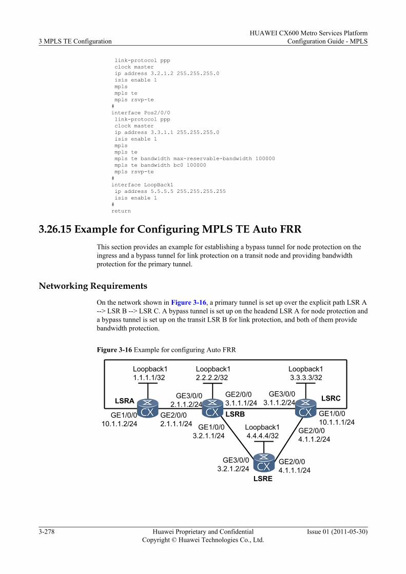
link-protocol ppp clock master ip address 3.2.1.2 255.255.255.0 isis enable 1 mpls mpls te mpls rsvp-te#interface Pos2/0/0 link-protocol ppp clock master ip address 3.3.1.1 255.255.255.0 isis enable 1 mpls mpls te mpls te bandwidth max-reservable-bandwidth 100000 mpls te bandwidth bc0 100000 mpls rsvp-te#interface LoopBack1 ip address 5.5.5.5 255.255.255.255 isis enable 1#return
3.26.15 Example for Configuring MPLS TE Auto FRRThis section provides an example for establishing a bypass tunnel for node protection on theingress and a bypass tunnel for link protection on a transit node and providing bandwidthprotection for the primary tunnel.
Networking Requirements
On the network shown in Figure 3-16, a primary tunnel is set up over the explicit path LSR A--> LSR B --> LSR C. A bypass tunnel is set up on the headend LSR A for node protection anda bypass tunnel is set up on the transit LSR B for link protection, and both of them providebandwidth protection.
Figure 3-16 Example for configuring Auto FRR
Loopback14.4.4.4/32
Loopback12.2.2.2/32
GE2/0/02.1.1.1/24
GE3/0/02.1.1.2/24LSRA
GE2/0/03.1.1.1/24
GE3/0/03.1.1.2/24
LSRB
LSRC
LSRE
GE1/0/03.2.1.1/24
GE3/0/03.2.1.2/24
GE2/0/04.1.1.1/24
GE2/0/04.1.1.2/24
GE1/0/010.1.1.1/24
Loopback11.1.1.1/32
Loopback13.3.3.3/32
GE1/0/010.1.1.2/24
3 MPLS TE ConfigurationHUAWEI CX600 Metro Services Platform
Configuration Guide - MPLS
3-278 Huawei Proprietary and ConfidentialCopyright © Huawei Technologies Co., Ltd.
Issue 01 (2011-05-30)
Configuration RoadmapThe configuration roadmap is as follows:
1. Set up a primary tunnel, enable TE FRR in the tunnel interface view, and enable TE AutoFRR in the MPLS view.
2. Specify the bandwidth that the bypass tunnel can protect and the setup and holding prioritiesof the bypass tunnel.
Data PreparationTo complete the configuration, you need the following data.
l OSPF process ID and OSPF area ID of each LSRl Maximum reservable bandwidth and BC bandwidth of the linkl Explicit path through which the primary tunnel passesl Name of the primary tunnel interface, IP address, destination address, tunnel ID, tunnel
signaling protocol (RSVP-TE), and tunnel bandwidth
Procedure
Step 1 Configure the IP address for each interface.
Configure the IP address and mask for each interface including Loopback interfaces as shownin Figure 3-16. The detailed configuration is not provided here.
Step 2 Configure OSPF on all LSRs to advertise the routes of each network segment and the host routeof each LSR ID.
Configure OSPF on all LSRs to advertise the host route of each LSR ID. The detailedconfiguration is not provided here.
After the configuration, run the display ip routing-table command on each LSR. You can viewthat the LSRs have learned the host routes of LSR IDs from each other.
Step 3 Configure the basic MPLS functions and enable MPLS TE, RSVP-TE, and CSPF.
# Configure LSR A.
[LSRA] mpls lsr-id 1.1.1.1[LSRA] mpls[LSRA-mpls] mpls te[LSRA-mpls] mpls rsvp-te[LSRA-mpls] mpls te cspf[LSRA-mpls] quit[LSRA] interface gigabitethernet 2/0/0[LSRA-GigabitEthernet2/0/0] mpls[LSRA-GigabitEthernet2/0/0] mpls te[LSRA-GigabitEthernet2/0/0] mpls rsvp-te[LSRA-GigabitEthernet2/0/0] quit[LSRA] interface gigabitethernet 1/0/0[LSRA-GigabitEthernet1/0/0] mpls[LSRA-GigabitEthernet1/0/0] mpls te[LSRA-GigabitEthernet1/0/0] mpls rsvp-te[LSRA-GigabitEthernet1/0/0] quit
NOTE
The configurations of LSR B, LSR C, and LSR D are similar to that of LSR A, and are not provided here.
CSPF is enabled only on LSR A and LSR B.
HUAWEI CX600 Metro Services PlatformConfiguration Guide - MPLS 3 MPLS TE Configuration
Issue 01 (2011-05-30) Huawei Proprietary and ConfidentialCopyright © Huawei Technologies Co., Ltd.
3-279
Step 4 Configure OSPF TE.
# Configure LSR A.
[LSRA] ospf[LSRA-ospf-1] opaque-capability enable[LSRA-ospf-1] area 0[LSRA-ospf-1-area-0.0.0.0] mpls-te enable[LSRA-ospf-1-area-0.0.0.0] quit[LSRA-ospf-1] quit
# Configure LSR B.
[LSRB] ospf[LSRB-ospf-1] opaque-capability enable[LSRB-ospf-1] area 0[LSRB-ospf-1-area-0.0.0.0] mpls-te enable[LSRB-ospf-1-area-0.0.0.0] quit[LSRB-ospf-1] quit
# Configure LSR C.
[LSRC] ospf[LSRC-ospf-1] opaque-capability enable[LSRC-ospf-1] area 0[LSRC-ospf-1-area-0.0.0.0] mpls-te enable[LSRC-ospf-1-area-0.0.0.0] quit[LSRC-ospf-1] quit
# Configure LSR D.
[LSRD] ospf[LSRD-ospf-1] opaque-capability enable[LSRD-ospf-1] area 0[LSRD-ospf-1-area-0.0.0.0] mpls-te enable[LSRD-ospf-1-area-0.0.0.0] quit[LSRD-ospf-1] quit
Step 5 Configure the MPLS TE link bandwidth.
Set the maximum reservable bandwidth for the link to 10 Mbit/s, the BC0 bandwidth to 10 Mbit/s and the BC1 bandwidth to 3 Mbit/s.
# Configure LSR A.
[LSRA] interface gigabitethernet 2/0/0[LSRA-GigabitEthernet2/0/0] mpls te bandwidth max-reservable-bandwidth 10000[LSRA-GigabitEthernet2/0/0] mpls te bandwidth bc0 10000 bc1 3000
The outgoing interfaces on the link through which the primary and bypass tunnels pass use aresimilar to these configurations, and are not provided here.
Step 6 Configure the explicit path for the primary tunnel.[LSRA] explicit-path master[LSRA-explicit-path-master] next hop 2.1.1.2[LSRA-explicit-path-master] next hop 3.1.1.2
Step 7 Enable TE Auto FRR.
# Configure LSR A.
[LSRA] mpls[LSRA-mpls] mpls te auto-frr
# Configure LSR B.
[LSRB] mpls[LSRB-mpls] mpls te auto-frr
3 MPLS TE ConfigurationHUAWEI CX600 Metro Services Platform
Configuration Guide - MPLS
3-280 Huawei Proprietary and ConfidentialCopyright © Huawei Technologies Co., Ltd.
Issue 01 (2011-05-30)
Step 8 Configure the primary tunnel.[LSRA] interface tunnel2/0/0[LSRA-Tunnel2/0/0] ip address unnumbered interface loopBack1[LSRA-Tunnel2/0/0] tunnel-protocol mpls te[LSRA-Tunnel2/0/0] destination 3.3.3.3[LSRA-Tunnel2/0/0] mpls te tunnel-id 200[LSRA-Tunnel2/0/0] mpls te record-route label[LSRA-Tunnel2/0/0] mpls te path explicit-path master[LSRA-Tunnel2/0/0] mpls te bandwidth ct0 400[LSRA-Tunnel2/0/0] mpls te priority 4 3[LSRA-Tunnel2/0/0] mpls te fast-reroute bandwidth[LSRA-Tunnel2/0/0] mpls te bypass-attributes bandwidth 200 priority 5 4[LSRA-Tunnel2/0/0] mpls te commit[LSRA-Tunnel2/0/0] quit
Step 9 Verify the configuration.
Run the display mpls te tunnel name Tunnel2/0/0 verbose command on the ingress LSR A.You can view information about the primary tunnel and the auto bypass tunnel.
[LSRA] display mpls te tunnel name Tunnel2/0/0 verbose No : 1 Tunnel-Name : Tunnel2/0/0 TunnelIndex : 1 LSP Index : 3072 Session ID : 200 LSP ID : 1 Lsr Role : Ingress LSP Type : Primary
Ingress LSR ID : 1.1.1.1 Egress LSR ID : 3.3.3.3 In-Interface : - Out-Interface : GE2/0/0 Sign-Protocol : RSVP TE Resv Style : SE IncludeAnyAff : 0x0 ExcludeAnyAff : 0x0 IncludeAllAff : 0x0 LspConstraint : - ER-Hop Table Index : - AR-Hop Table Index: 2 C-Hop Table Index : - PrevTunnelIndexInSession: - NextTunnelIndexInSession: - PSB Handle : 65546 Created Time : 2009/03/30 09:52:03 -------------------------------- DS-TE Information -------------------------------- Bandwidth Reserved Flag : Reserved CT0 Bandwidth(Kbit/sec) : 10000 CT1 Bandwidth(Kbit/sec): 0 CT2 Bandwidth(Kbit/sec) : 0 CT3 Bandwidth(Kbit/sec): 0 CT4 Bandwidth(Kbit/sec) : 0 CT5 Bandwidth(Kbit/sec): 0 CT6 Bandwidth(Kbit/sec) : 0 CT7 Bandwidth(Kbit/sec): 0 Setup-Priority : 7 Hold-Priority : 7 -------------------------------- FRR Information -------------------------------- Primary LSP Info TE Attribute Flag : 0x63 Protected Flag : 0x1 Bypass In Use : Not Used Bypass Tunnel Id : 67141670 BypassTunnel : Tunnel Index[Tunnel0/0/2048], InnerLabel[3] Bypass Lsp ID : - FrrNextHop : 10.1.1.1 ReferAutoBypassHandle : 2049 FrrPrevTunnelTableIndex : - FrrNextTunnelTableIndex: - Bypass Attribute(Not configured) Setup Priority : - Hold Priority : - HopLimit : - Bandwidth : - IncludeAnyGroup : - ExcludeAnyGroup : - IncludeAllGroup : - Bypass Unbound Bandwidth Info(Kbit/sec) CT0 Unbound Bandwidth : - CT1 Unbound Bandwidth: - CT2 Unbound Bandwidth : - CT3 Unbound Bandwidth: - CT4 Unbound Bandwidth : - CT5 Unbound Bandwidth: -
HUAWEI CX600 Metro Services PlatformConfiguration Guide - MPLS 3 MPLS TE Configuration
Issue 01 (2011-05-30) Huawei Proprietary and ConfidentialCopyright © Huawei Technologies Co., Ltd.
3-281
CT6 Unbound Bandwidth : - CT7 Unbound Bandwidth: - -------------------------------- BFD Information -------------------------------- NextSessionTunnelIndex : - PrevSessionTunnelIndex: - NextLspId : - PrevLspId : -
You can view that the primary tunnel is bound to the Auto bypass tunnel, that is, Tunnel 0/0/2048.
Run the display mpls te tunnel name Tunnel0/0/2048 verbose command. You can viewdetailed information about the Auto bypass tunnel. The bandwidth, setup priority, and holdingpriority of the Auto bypass tunnel are the same as the bypass-attributes of the primary tunnel.
[LSRA] display mpls te tunnel name Tunnel0/0/2048 verbose No : 1 Tunnel-Name : Tunnel0/0/2048 TunnelIndex : 3 LSP Index : 2051 Session ID : 1026 LSP ID : 1 Lsr Role : Ingress Lsp Type : Primary Ingress LSR ID : 1.1.1.1 Egress LSR ID : 3.3.3.3 In-Interface : - Out-Interface : GE1/0/0 Sign-Protocol : RSVP TE Resv Style : SE IncludeAnyAff : 0x0 ExcludeAnyAff : 0x0 IncludeAllAff : 0x0 LspConstraint : - ER-Hop Table Index : - AR-Hop Table Index: 3 C-Hop Table Index : 3 PrevTunnelIndexInSession: - NextTunnelIndexInSession: - PSB Handle : 1027 Created Time : 2010/07/01 13:35:53 UTC-08:00 -------------------------------- DS-TE Information -------------------------------- Bandwidth Reserved Flag : Reserved CT0 Bandwidth(Kbit/sec) : 200 CT1 Bandwidth(Kbit/sec): 0 CT2 Bandwidth(Kbit/sec) : 0 CT3 Bandwidth(Kbit/sec): 0 CT4 Bandwidth(Kbit/sec) : 0 CT5 Bandwidth(Kbit/sec): 0 CT6 Bandwidth(Kbit/sec) : 0 CT7 Bandwidth(Kbit/sec): 0 Setup-Priority : 5 Hold-Priority : 4 -------------------------------- FRR Information -------------------------------- Primary LSP Info TE Attribute Flag : 0x3 Protected Flag : 0x0 Bypass In Use : Not Exists Bypass Tunnel Id : - BypassTunnel : - Bypass Lsp ID : - FrrNextHop : - ReferAutoBypassHandle : - FrrPrevTunnelTableIndex : - FrrNextTunnelTableIndex: - Bypass Attribute(Not configured) Setup Priority : - Hold Priority : - HopLimit : - Bandwidth : - IncludeAnyGroup : - ExcludeAnyGroup : - IncludeAllGroup : - Bypass Unbound Bandwidth Info(Kbit/sec) CT0 Unbound Bandwidth : - CT1 Unbound Bandwidth: - CT2 Unbound Bandwidth : - CT3 Unbound Bandwidth: - CT4 Unbound Bandwidth : - CT5 Unbound Bandwidth: - CT6 Unbound Bandwidth : - CT7 Unbound Bandwidth: - -------------------------------- BFD Information -------------------------------- NextSessionTunnelIndex : - PrevSessionTunnelIndex: - NextLspId : - PrevLspId : -
3 MPLS TE ConfigurationHUAWEI CX600 Metro Services Platform
Configuration Guide - MPLS
3-282 Huawei Proprietary and ConfidentialCopyright © Huawei Technologies Co., Ltd.
Issue 01 (2011-05-30)
You can view that the Auto bypass tunnel protects traffic on GE 2/0/0 but not other threeinterfaces on the primary tunnel. The bandwidth of the Auto bypass tunnel is 200 kbit/s, and itssetup and holding priorities are 5 and 4 respectively.
Run the display mpls te tunnel path command on LSR A. You can view information about theprimary tunnel and the Auto bypass tunnel, and node and bandwidth protection that are providedfor the outgoing interface of the primary tunnel.
[LSRA] display mpls te tunnel pathTunnel Interface Name : Tunnel2/0/0 Lsp ID : 1.1.1.1 :200:1 Hop Information Hop 0 2.1.1.1 Local-Protection available | bandwidth | node Hop 1 2.1.1.2 Label 106497 Hop 2 2.2.2.2 Hop 3 3.1.1.1 Local-Protection available | bandwidth Hop 4 3.1.1.2 Label 3 Hop 5 3.3.3.3Tunnel Interface Name : Tunnel0/0/2048 Lsp ID : 2.2.2.2 :2049 :2 Hop Information Hop 0 2.2.2.2 Hop 1 3.2.1.1 Hop 2 3.2.1.2 Hop 3 4.4.4.4 Hop 4 4.1.1.1 Hop 5 4.1.1.2 Hop 6 3.3.3.3 Tunnel Interface Name : Tunnel0/0/2048 Lsp ID : 1.1.1.1 :2049:3 Hop Information Hop 0 10.1.1.2 Hop 1 10.1.1.1 Hop 2 3.3.3.3
----End
Configuration Filesl Configuration file of LSR A
# sysname LSRA# mpls lsr-id 1.1.1.1 mpls mpls te mpls te auto-frr mpls rsvp-te mpls te cspf# explicit-path master next hop 2.1.1.2 next hop 3.1.1.2# interface GigabitEthernet1/0/0 ip address 10.1.1.2 255.255.255.0 mpls mpls te mpls te bandwidth max-reservable-bandwidth 10000 mpls te bandwidth bc0 10000 bc1 3000 mpls rsvp-te# interface GigabitEthernet2/0/0 ip address 2.1.1.1 255.255.255.0 mpls mpls te mpls te bandwidth max-reservable-bandwidth 10000
HUAWEI CX600 Metro Services PlatformConfiguration Guide - MPLS 3 MPLS TE Configuration
Issue 01 (2011-05-30) Huawei Proprietary and ConfidentialCopyright © Huawei Technologies Co., Ltd.
3-283
mpls te bandwidth bc0 10000 bc1 3000 mpls rsvp-te#interface LoopBack1 ip address 1.1.1.1 255.255.255.255#interface Tunnel2/0/0 ip address unnumbered interface LoopBack1 tunnel-protocol mpls te destination 3.3.3.3 mpls te tunnel-id 200 mpls te record-route label mpls te bandwidth ct0 400 mpls te path explicit-path master mpls te priority 4 3 mpls te fast-reroute bandwidth mpls te bypass-attributes bandwidth 200 priority 5 4 mpls te commit#ospf 1 opaque-capability enable area 0.0.0.0 network 10.1.1.0 0.0.0.255 network 2.1.1.0 0.0.0.255 network 1.1.1.1 0.0.0.0 mpls-te enable#return
l Configuration file of LSR B# sysname LSRB# mpls lsr-id 2.2.2.2 mpls mpls te mpls te auto-frr mpls rsvp-te mpls te cspf#interface GigabitEthernet1/0/0 ip address 3.2.1.1 255.255.255.0 mpls mpls te mpls te bandwidth max-reservable-bandwidth 10000 mpls te bandwidth bc0 10000 bc1 3000 mpls rsvp-te# interface GigabitEthernet2/0/0 ip address 3.1.1.1 255.255.255.0 mpls mpls te mpls te bandwidth max-reservable-bandwidth 10000 mpls te bandwidth bc0 10000 bc1 3000 mpls rsvp-te#interface GigabitEthernet3/0/0 ip address 2.1.1.2 255.255.255.0 mpls mpls te mpls rsvp-te#interface LoopBack1 ip address 2.2.2.2 255.255.255.255# ospf 1 opaque-capability enable area 0.0.0.0 network 3.1.1.0 0.0.0.255 network 3.2.1.0 0.0.0.255
3 MPLS TE ConfigurationHUAWEI CX600 Metro Services Platform
Configuration Guide - MPLS
3-284 Huawei Proprietary and ConfidentialCopyright © Huawei Technologies Co., Ltd.
Issue 01 (2011-05-30)
network 2.1.1.0 0.0.0.255 network 2.2.2.2 0.0.0.0 mpls-te enable#return
l Configuration file of LSR C# sysname LSRC# mpls lsr-id 3.3.3.3 mpls mpls te mpls rsvp-te#interface GigabitEthernet1/0/0 ip address 10.1.1.1 255.255.255.0 mpls mpls te mpls rsvp-te#interface GigabitEthernet2/0/0 ip address 4.1.1.2 255.255.255.0 mpls mpls te mpls rsvp-te#interface GigabitEthernet3/0/0 ip address 3.1.1.2 255.255.255.0 mpls mpls te mpls rsvp-te#interface LoopBack1 ip address 3.3.3.3 255.255.255.255#ospf 1 opaque-capability enable area 0.0.0.0 network 10.1.1.0 0.0.0.255 network 3.1.1.0 0.0.0.255 network 4.1.1.0 0.0.0.255 network 3.3.3.3 0.0.0.0 mpls-te enable#return
l Configuration file of LSR D# sysname LSRD# mpls lsr-id 4.4.4.4 mpls mpls te mpls rsvp-te#interface GigabitEthernet2/0/0 ip address 4.1.1.1 255.255.255.0 mpls mpls te mpls te bandwidth max-reservable-bandwidth 10000 mpls te bandwidth bc0 10000 bc1 3000 mpls rsvp-te#interface GigabitEthernet3/0/0 ip address 3.2.1.2 255.255.255.0 mpls mpls te mpls rsvp-te#
HUAWEI CX600 Metro Services PlatformConfiguration Guide - MPLS 3 MPLS TE Configuration
Issue 01 (2011-05-30) Huawei Proprietary and ConfidentialCopyright © Huawei Technologies Co., Ltd.
3-285
interface LoopBack1 ip address 4.4.4.4 255.255.255.255#ospf 1 opaque-capability enable area 0.0.0.0 network 3.2.1.0 0.0.0.255 network 4.1.1.0 0.0.0.255 network 4.4.4.4 0.0.0.0 mpls-te enable#return
3.26.16 Example for Configuring RSVP Key Authentication (RSVP-TE FRR)
This section provides an example for configuring RSVP authentication in the MPLS view toimprove network security in the TE FRR networking.
Networking RequirementsOn the network shown in Figure 3-17, the primary tunnel is along the path LSR A -> LSR B -> LSR C -> LSR D, and FRR is required on the link between LSR B and LSR C for protection.
A bypass tunnel is set up along the path LSR B -> LSR E -> LSR C. LSR B functions as thePLR and LSR C functions as the MP.
The primary and bypass MPLS TE tunnels are set up by using explicit paths. RSVP-TE is usedas the signaling protocol.
The RSVP authentication needs to be configured on LSR B and LSR C. In this example, LSRB and LSR C are configured as neighboring nodes by using their LSR IDs, and RSVP keyauthentication is enabled to achieve higher reliability.
3 MPLS TE ConfigurationHUAWEI CX600 Metro Services Platform
Configuration Guide - MPLS
3-286 Huawei Proprietary and ConfidentialCopyright © Huawei Technologies Co., Ltd.
Issue 01 (2011-05-30)
Figure 3-17 Networking diagram of the MPLS TE FRR-based RSVP key authentication
Loopback15.5.5.5/32
Loopback12.2.2.2/32
GE1/0/02.1.1.1/24
GE1/0/02.1.1.2/24
LSRA
GE2/0/03.1.1.1/24
GE2/0/03.1.1.2/24
LSRB
LSRC
LSRE
POS3/0/03.2.1.1/24
POS1/0/03.2.1.2/24
POS2/0/03.3.1.1/24
POS3/0/03.3.1.2/24
Primary LSP
Bypass LSP
LSRD
GE1/0/04.1.1.1/24
GE1/0/04.1.1.2/24
Loopback11.1.1.1/32 Loopback1
3.3.3.3/32
Loopback14.4.4.4/32
Configuration Roadmap
The configuration roadmap is as follows:
1. Configure MPLS TE FRR based on Example for Configuring MPLS TE FRR.2. Configure RSVP key authentication on LSR B and LSR C of the tunnel, preventing forged
Resv messages from consuming network resources.
Data Preparation
To complete the configuration, you need the following data:
l MPLS LSR ID of each devicel Local password and key for RSVP authenticationl Data listed in "Data Preparation" of Example for Configuring MPLS TE FRR
Procedure
Step 1 Configure MPLS TE FRR.
Configure the primary tunnel and bypass tunnel based on Example for Configuring MPLS TEFRR and then bind the two tunnels.
HUAWEI CX600 Metro Services PlatformConfiguration Guide - MPLS 3 MPLS TE Configuration
Issue 01 (2011-05-30) Huawei Proprietary and ConfidentialCopyright © Huawei Technologies Co., Ltd.
3-287
Step 2 Configure RSVP key authentication on LSR B and LSR C to enhance security of packettransmission. In addition, check whether the RSVP key authentication is successfullyconfigured, configure the RSVP-TE handshake function, and set a local password.
# Configure RSVP key authentication on LSR B.
[LSRB] mpls rsvp-te peer 3.3.3.3[LSRB-mpls-rsvp-te-peer-3.3.3.3] mpls rsvp-te authentication plain huawei[LSRB-mpls-rsvp-te-peer-3.3.3.3] mpls rsvp-te authentication handshake beijingHW
# Configure RSVP key authentication on LSR C.
[LSRC] mpls rsvp-te peer 2.2.2.2[LSRC-mpls-rsvp-te-peer-2.2.2.2] mpls rsvp-te authentication plain huawei[LSRC-mpls-rsvp-te-peer-2.2.2.2] mpls rsvp-te authentication handshake beijingHW
Step 3 Verify the configuration.
# Run the display mpls rsvp-te statistics global command on LSR B. You can view the statusof the RSVP key authentication. If the command output shows that the values of theSendChallengeMsgCounter field, RecChallengeMsgCounter field, SendResponseMsgCounterfield, and RecResponseMsgCounter field are not zero, it indicates that the PLR and the MPsuccessfully shake hands with each other and RSVP key authentication is configuredsuccessfully.
<LSRB> display mpls rsvp-te statistics global LSR ID: 2.2.2.2 LSP Count: 2 PSB Count: 1 RSB Count: 1 RFSB Count: 0
Total Statistics Information: PSB CleanupTimeOutCounter: 0 RSB CleanupTimeOutCounter: 0 SendPacketCounter: 104 RecPacketCounter: 216 SendCreatePathCounter: 7 RecCreatePathCounter: 57 SendRefreshPathCounter: 48 RecRefreshPathCounter: 28 SendCreateResvCounter: 4 RecCreateResvCounter: 4 SendRefreshResvCounter: 26 RecRefreshResvCounter: 49 SendResvConfCounter: 0 RecResvConfCounter: 0 SendHelloCounter: 0 RecHelloCounter: 0 SendAckCounter: 0 RecAckCounter: 0 SendPathErrCounter: 1 RecPathErrCounter: 0 SendResvErrCounter: 0 RecResvErrCounter: 0 SendPathTearCounter: 0 RecPathTearCounter: 1 SendResvTearCounter: 1 RecResvTearCounter: 1 SendSrefreshCounter: 0 RecSrefreshCounter: 0 SendAckMsgCounter: 0 RecAckMsgCounter: 0 SendChallengeMsgCounter: 1 RecChallengeMsgCounter: 1 SendResponseMsgCounter: 1 RecResponseMsgCounter: 1 SendErrMsgCounter: 1 RecErrMsgCounter: 0 ResourceReqFaultCounter: 0 Bfd neighbor count: 1 Bfd session count: 0
# Shut down the protected outbound interface on the PLR.
[LSRB] interface gigabitethernet 2/0/0[LSRB-GigabitEthernet2/0/0] shutdown
# Run the display interface tunnel 1/0/0 command on LSR A to view the status of the primarytunnel. You can see that the tunnel interface is Up.
# Run the tracert lsp te tunnel 1/0/0 command on LSR A. You can view the path by which thetunnel passes.
[LSRA] tracert lsp te tunnel 1/0/0 LSP Trace Route FEC: TE TUNNEL IPV4 SESSION QUERY Tunnel1/0/0 , press CTRL_C to break. TTL Replier Time Type Downstream
3 MPLS TE ConfigurationHUAWEI CX600 Metro Services Platform
Configuration Guide - MPLS
3-288 Huawei Proprietary and ConfidentialCopyright © Huawei Technologies Co., Ltd.
Issue 01 (2011-05-30)
0 Ingress 2.1.1.2/[13312 ] 1 2.1.1.2 1 ms Transit 3.2.1.2/[13312 13312 ] 2 3.2.1.2 16 ms Transit 3.3.1.2/[3 ] 3 3.3.1.2 1 ms Transit 4.1.1.2/[3 ] 4 4.1.1.2 1 ms Egress
The command output shows that traffic is switched to the bypass tunnel.
# Run the display mpls te tunnel name tunnel1/0/0 verbose command on LSR B. You can seethat the bypass tunnel is working.[LSRB] display mpls te tunnel name tunnel1/0/0 verbose No : 1 Tunnel-Name : Tunnel1/0/0 TunnelIndex : 1 LSP Index : 4098 Session ID : 100 LSP ID : 1 Lsr Role : Transit LSP Type : Primary Ingress LSR ID : 1.1.1.1 Egress LSR ID : 4.4.4.4 In-Interface : GE1/0/0 Out-Interface : GE2/0/0 Sign-Protocol : RSVP TE Resv Style : SE IncludeAnyAff : 0x0 ExcludeAnyAff : 0x0 IncludeAllAff : 0x0 ER-Hop Table Index : 3 AR-Hop Table Index: 12 C-Hop Table Index : 50 PrevTunnelIndexInSession: - NextTunnelIndexInSession: - PSB Handle : 66000 Created Time : 2009/01/12 10:09:10 -------------------------------- DS-TE Information -------------------------------- Bandwidth Reserved Flag : Unreserved CT0 Bandwidth(Kbit/sec) : 50000 CT1 Bandwidth(Kbit/sec): 0 CT2 Bandwidth(Kbit/sec) : 0 CT3 Bandwidth(Kbit/sec): 0 CT4 Bandwidth(Kbit/sec) : 0 CT5 Bandwidth(Kbit/sec): 0 CT6 Bandwidth(Kbit/sec) : 0 CT7 Bandwidth(Kbit/sec): 0 Setup-Priority : 7 Hold-Priority : 7 -------------------------------- FRR Information -------------------------------- Primary LSP Info TE Attribute Flag : 0x63 Protected Flag : 0x1 Bypass In Use : In Use Bypass Tunnel Id : 67141670 BypassTunnel : Tunnel Index[Tunnel3/0/0], InnerLabel[1024] Bypass Lsp ID : 9 FrrNextHop : 3.3.1.2 ReferAutoBypassHandle : - FrrPrevTunnelTableIndex : - FrrNextTunnelTableIndex: - Bypass Attribute(Not configured) Setup Priority : - Hold Priority : - HopLimit : - Bandwidth : - IncludeAnyGroup : - ExcludeAnyGroup : - IncludeAllGroup : - Bypass Unbound Bandwidth Info(Kbit/sec) CT0 Unbound Bandwidth : - CT1 Unbound Bandwidth: - CT2 Unbound Bandwidth : - CT3 Unbound Bandwidth: - CT4 Unbound Bandwidth : - CT5 Unbound Bandwidth: - CT6 Unbound Bandwidth : - CT7 Unbound Bandwidth: - -------------------------------- BFD Information -------------------------------- NextSessionTunnelIndex : - PrevSessionTunnelIndex: - NextLspId : - PrevLspId : -
# Run the display mpls rsvp-te peer command. You can see whether the bypass tunnel issuccessfully set up.[LSRB] display mpls rsvp-te peerRemote Node id Neighbor
HUAWEI CX600 Metro Services PlatformConfiguration Guide - MPLS 3 MPLS TE Configuration
Issue 01 (2011-05-30) Huawei Proprietary and ConfidentialCopyright © Huawei Technologies Co., Ltd.
3-289
Neighbor Addr: ----- SrcInstance: 0xDAC29CB4 NbrSrcInstance: 0x0 PSB Count: 1 RSB Count: 0 Hello Type Sent: NONE SRefresh Enable: NO Last valid seq # rcvd: NULL
Interface: gigabitethernet1/0/0 Neighbor Addr: 2.1.1.1 SrcInstance: 0xDAC29CB4 NbrSrcInstance: 0x0 PSB Count: 1 RSB Count: 0 Hello Type Sent: NONE SRefresh Enable: NO Last valid seq # rcvd: NULL
Interface: gigabitethernet2/0/0 Neighbor Addr: 3.1.1.2 SrcInstance: 0xDAC29CB4 NbrSrcInstance: 0x0 PSB Count: 0 RSB Count: 0 Hello Type Sent: NONE SRefresh Enable: NO Last valid seq # rcvd: NULL
Interface: POS1/0/0 Neighbor Addr: 3.2.1.2 SrcInstance: 0xDAC29CB4 NbrSrcInstance: 0x0 PSB Count: 0 RSB Count: 1 Hello Type Sent: NONE SRefresh Enable: NO Last valid seq # rcvd: NULL
The command output shows that the number of RSBs on POS 1/0/0 of LSR B is not zero. Thisindicates that RSVP key authentication is successfully configured on LSR B and its neighborLSR E, and the resources are successfully reserved.
----End
Configuration Filesl Configuration file of LSR A
# sysname LSRA# mpls lsr-id 1.1.1.1 mpls mpls te mpls rsvp-te mpls te cspf# explicit-path pri-path next hop 2.1.1.2 next hop 3.1.1.2 next hop 4.1.1.2 next hop 4.4.4.4#isis 1 is-level level-2 cost-style wide network-entity 00.0005.0000.0000.0001.00 traffic-eng level-2#interface GigabitEthernet1/0/0 ip address 2.1.1.1 255.255.255.0 isis enable 1 mpls mpls te mpls te bandwidth max-reservable-bandwidth 100000 mpls te bandwidth bc0 100000
3 MPLS TE ConfigurationHUAWEI CX600 Metro Services Platform
Configuration Guide - MPLS
3-290 Huawei Proprietary and ConfidentialCopyright © Huawei Technologies Co., Ltd.
Issue 01 (2011-05-30)
mpls rsvp-te#interface LoopBack1 ip address 1.1.1.1 255.255.255.255 isis enable 1#interface Tunnel1/0/0 ip address unnumbered interface LoopBack1 tunnel-protocol mpls te destination 4.4.4.4mpls te record-route label mpls te path explicit-path pri-pathmpls te tunnel-id 100 mpls te bandwidth ct0 50000mpls te fast-reroute mpls te commit#return
l Configuration file of LSR B# mpls lsr-id 2.2.2.2 mpls mpls te mpls te timer fast-reroute 5 mpls rsvp-te mpls te cspf# explicit-path by-path next hop 3.2.1.2 next hop 3.3.1.2 next hop 3.3.3.3#isis 1 is-level level-2 cost-style wide network-entity 00.0005.0000.0000.0002.00 traffic-eng level-2#interface GigabitEthernet1/0/0 ip address 2.1.1.2 255.255.255.0 isis enable 1 mpls mpls te mpls rsvp-te#interface GigabitEthernet2/0/0 ip address 3.1.1.1 255.255.255.0 isis enable 1 mpls mpls te mpls te bandwidth max-reservable-bandwidth 100000 mpls te bandwidth bc0 100000 mpls rsvp-te#interface Pos3/0/0 link-protocol ppp ip address 3.2.1.1 255.255.255.0 isis enable 1 mpls mpls te mpls te bandwidth max-reservable-bandwidth 100000 mpls te bandwidth bc0 100000 mpls rsvp-te#interface LoopBack1 ip address 2.2.2.2 255.255.255.255 isis enable 1#interface Tunnel3/0/0
HUAWEI CX600 Metro Services PlatformConfiguration Guide - MPLS 3 MPLS TE Configuration
Issue 01 (2011-05-30) Huawei Proprietary and ConfidentialCopyright © Huawei Technologies Co., Ltd.
3-291
ip address unnumbered interface LoopBack1 tunnel-protocol mpls te destination 3.3.3.3 mpls te tunnel-id 300 mpls te record-route mpls te path explicit-path by-path mpls te bandwidth ct0 100000 mpls te bypass-tunnel mpls te protected-interface GigabitEthernet 2/0/0 mpls te commitmpls rsvp-te peer 3.3.3.3 mpls rsvp-te authentication plain huawei mpls rsvp-te authentication handshake beijingHW#return
l Configuration file of LSR C# sysname LSRC# mpls lsr-id 3.3.3.3 mpls mpls te mpls rsvp-te#isis 1 is-level level-2 cost-style wide network-entity 00.0005.0000.0000.0003.00 traffic-eng level-2#interface GigabitEthernet1/0/0 ip address 4.1.1.1 255.255.255.0 isis enable 1 mpls mpls te mpls te bandwidth max-reservable-bandwidth 100000 mpls te bandwidth bc0 100000 mpls rsvp-te#interface GigabitEthernet2/0/0 ip address 3.1.1.2 255.255.255.0 isis enable 1 mpls mpls te mpls rsvp-te#interface Pos3/0/0 link-protocol ppp ip address 3.3.1.2 255.255.255.0 isis enable 1 mpls mpls te mpls rsvp-te#interface LoopBack1 ip address 3.3.3.3 255.255.255.255 isis enable 1mpls rsvp-te peer 2.2.2.2 mpls rsvp-te authentication plain huawei mpls rsvp-te authentication handshake beijingHW#return
l Configuration file of LSR D# sysname LSRD# mpls lsr-id 4.4.4.4 mpls
3 MPLS TE ConfigurationHUAWEI CX600 Metro Services Platform
Configuration Guide - MPLS
3-292 Huawei Proprietary and ConfidentialCopyright © Huawei Technologies Co., Ltd.
Issue 01 (2011-05-30)
mpls te mpls rsvp-te#isis 1 is-level level-2 cost-style wide network-entity 00.0005.0000.0000.0004.00 traffic-eng level-2#interface GigabitEthernet1/0/0 ip address 4.1.1.2 255.255.255.0 isis enable 1 mpls mpls te mpls rsvp-te#interface LoopBack1 ip address 4.4.4.4 255.255.255.255 isis enable 1#return
l Configuration file of LSR E# sysname LSRE# mpls lsr-id 5.5.5.5 mpls mpls te mpls rsvp-te#isis 1 is-level level-2 cost-style wide network-entity 00.0005.0000.0000.0005.00 traffic-eng level-2#interface Pos1/0/0 link-protocol ppp clock master ip address 3.2.1.2 255.255.255.0 isis enable 1 mpls mpls te mpls rsvp-te#interface Pos2/0/0 link-protocol ppp clock master ip address 3.3.1.1 255.255.255.0 isis enable 1 mpls mpls te mpls te bandwidth max-reservable-bandwidth 100000 mpls te bandwidth bc0 100000 mpls rsvp-te#interface LoopBack1 ip address 5.5.5.5 255.255.255.255 isis enable 1#return
HUAWEI CX600 Metro Services PlatformConfiguration Guide - MPLS 3 MPLS TE Configuration
Issue 01 (2011-05-30) Huawei Proprietary and ConfidentialCopyright © Huawei Technologies Co., Ltd.
3-293
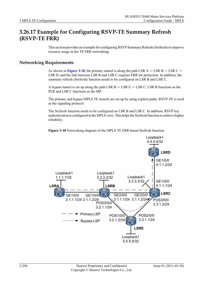
3.26.17 Example for Configuring RSVP-TE Summary Refresh(RSVP-TE FRR)
This section provides an example for configuring RSVP Summary Refresh (Srefresh) to improveresource usage in the TE FRR networking.
Networking Requirements
As shown in Figure 3-18, the primary tunnel is along the path LSR A -> LSR B -> LSR C ->LSR D, and the link between LSR B and LSR C requires FRR for protection. In addition, thesummary refresh (Srefresh) function needs to be configured on LSR B and LSR C.
A bypass tunnel is set up along the path LSR B -> LSR E -> LSR C. LSR B functions as thePLR and LSR C functions as the MP.
The primary and bypass MPLS TE tunnels are set up by using explicit paths. RSVP-TE is usedas the signaling protocol.
The Srefresh function needs to be configured on LSR B and LSR C. In addition, RSVP keyauthentication is configured in the MPLS view. This helps the Srefresh function to achieve higherreliability.
Figure 3-18 Networking diagram of the MPLS TE FRR-based Srefresh function
Loopback15.5.5.5/32
Loopback12.2.2.2/32
GE1/0/02.1.1.1/24
GE1/0/02.1.1.2/24
LSRA
GE2/0/03.1.1.1/24
GE2/0/03.1.1.2/24
LSRB
LSRC
LSRE
POS3/0/03.2.1.1/24
POS1/0/03.2.1.2/24
POS2/0/03.3.1.1/24
POS3/0/03.3.1.2/24
Primary LSP
Bypass LSP
LSRD
GE1/0/04.1.1.1/24
GE1/0/04.1.1.2/24
Loopback11.1.1.1/32 Loopback1
3.3.3.3/32
Loopback14.4.4.4/32
3 MPLS TE ConfigurationHUAWEI CX600 Metro Services Platform
Configuration Guide - MPLS
3-294 Huawei Proprietary and ConfidentialCopyright © Huawei Technologies Co., Ltd.
Issue 01 (2011-05-30)
Configuration RoadmapThe configuration roadmap is as follows:
1. Configure MPLS TE FRR based on Example for Configuring MPLS TE FRR.2. Configure the Srefresh function on the PLR and MP along a tunnel to enhance transmission
reliability of RSVP messages and improve resource usage.
Data PreparationTo complete the configuration, you need the following data:
Data listed in "Data Preparation" of Example for Configuring MPLS TE FRR
Procedure
Step 1 Configure MPLS TE FRR.
You can configure the primary and bypass MPLS TE tunnels based on Example forConfiguring MPLS TE FRR, and then bind the two tunnels.
Step 2 Configure the Srefresh function on LSR B functioning as the PLR and LSR C functioning asthe MP.
# Configure the Srefresh function on LSR B.
[LSRB] mpls[LSRB-mpls] mpls rsvp-te srefresh[LSRB-mpls] quit
# Configure the Srefresh function on LSR C.
[LSRC] mpls[LSRC-mpls] mpls rsvp-te srefresh[LSRC-mpls] quit
Step 3 Verify the configuration.
# Run the display mpls rsvp-te statistics global command on LSR B. You can view the statusof the Srefresh function. If the command output shows that the values of theSendSrefreshCounter field, RecSrefreshCounter field, SendAckMsgCounter field, andRecAckMsgCounter field are not zero, it indicates that the Srefresh packets are successfullytransmitted.
[LSRB] display mpls rsvp-te statistics global LSR ID: 2.2.2.2 LSP Count: 2 PSB Count: 1 RSB Count: 1 RFSB Count: 0
Total Statistics Information: PSB CleanupTimeOutCounter: 0 RSB CleanupTimeOutCounter: 0 SendPacketCounter: 104 RecPacketCounter: 216 SendCreatePathCounter: 7 RecCreatePathCounter: 57 SendRefreshPathCounter: 48 RecRefreshPathCounter: 28 SendCreateResvCounter: 4 RecCreateResvCounter: 4 SendRefreshResvCounter: 26 RecRefreshResvCounter: 49 SendResvConfCounter: 0 RecResvConfCounter: 0 SendHelloCounter: 0 RecHelloCounter: 0 SendAckCounter: 0 RecAckCounter: 0 SendPathErrCounter: 1 RecPathErrCounter: 0 SendResvErrCounter: 0 RecResvErrCounter: 0 SendPathTearCounter: 0 RecPathTearCounter: 1 SendResvTearCounter: 1 RecResvTearCounter: 1
HUAWEI CX600 Metro Services PlatformConfiguration Guide - MPLS 3 MPLS TE Configuration
Issue 01 (2011-05-30) Huawei Proprietary and ConfidentialCopyright © Huawei Technologies Co., Ltd.
3-295
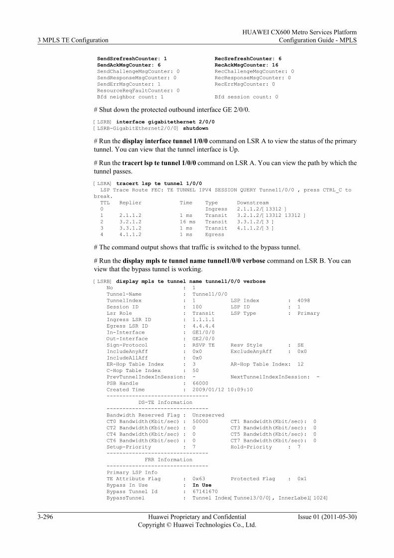
SendSrefreshCounter: 1 RecSrefreshCounter: 6 SendAckMsgCounter: 6 RecAckMsgCounter: 16 SendChallengeMsgCounter: 0 RecChallengeMsgCounter: 0 SendResponseMsgCounter: 0 RecResponseMsgCounter: 0 SendErrMsgCounter: 1 RecErrMsgCounter: 0 ResourceReqFaultCounter: 0 Bfd neighbor count: 1 Bfd session count: 0
# Shut down the protected outbound interface GE 2/0/0.
[LSRB] interface gigabitethernet 2/0/0[LSRB-GigabitEthernet2/0/0] shutdown
# Run the display interface tunnel 1/0/0 command on LSR A to view the status of the primarytunnel. You can view that the tunnel interface is Up.
# Run the tracert lsp te tunnel 1/0/0 command on LSR A. You can view the path by which thetunnel passes.
[LSRA] tracert lsp te tunnel 1/0/0 LSP Trace Route FEC: TE TUNNEL IPV4 SESSION QUERY Tunnel1/0/0 , press CTRL_C to break. TTL Replier Time Type Downstream 0 Ingress 2.1.1.2/[13312 ] 1 2.1.1.2 1 ms Transit 3.2.1.2/[13312 13312 ] 2 3.2.1.2 16 ms Transit 3.3.1.2/[3 ] 3 3.3.1.2 1 ms Transit 4.1.1.2/[3 ] 4 4.1.1.2 1 ms Egress
# The command output shows that traffic is switched to the bypass tunnel.
# Run the display mpls te tunnel name tunnel1/0/0 verbose command on LSR B. You canview that the bypass tunnel is working.
[LSRB] display mpls te tunnel name tunnel1/0/0 verbose No : 1 Tunnel-Name : Tunnel1/0/0 TunnelIndex : 1 LSP Index : 4098 Session ID : 100 LSP ID : 1 Lsr Role : Transit LSP Type : Primary Ingress LSR ID : 1.1.1.1 Egress LSR ID : 4.4.4.4 In-Interface : GE1/0/0 Out-Interface : GE2/0/0 Sign-Protocol : RSVP TE Resv Style : SE IncludeAnyAff : 0x0 ExcludeAnyAff : 0x0 IncludeAllAff : 0x0 ER-Hop Table Index : 3 AR-Hop Table Index: 12 C-Hop Table Index : 50 PrevTunnelIndexInSession: - NextTunnelIndexInSession: - PSB Handle : 66000 Created Time : 2009/01/12 10:09:10 -------------------------------- DS-TE Information -------------------------------- Bandwidth Reserved Flag : Unreserved CT0 Bandwidth(Kbit/sec) : 50000 CT1 Bandwidth(Kbit/sec): 0 CT2 Bandwidth(Kbit/sec) : 0 CT3 Bandwidth(Kbit/sec): 0 CT4 Bandwidth(Kbit/sec) : 0 CT5 Bandwidth(Kbit/sec): 0 CT6 Bandwidth(Kbit/sec) : 0 CT7 Bandwidth(Kbit/sec): 0 Setup-Priority : 7 Hold-Priority : 7 -------------------------------- FRR Information -------------------------------- Primary LSP Info TE Attribute Flag : 0x63 Protected Flag : 0x1 Bypass In Use : In Use Bypass Tunnel Id : 67141670 BypassTunnel : Tunnel Index[Tunnel3/0/0], InnerLabel[1024]
3 MPLS TE ConfigurationHUAWEI CX600 Metro Services Platform
Configuration Guide - MPLS
3-296 Huawei Proprietary and ConfidentialCopyright © Huawei Technologies Co., Ltd.
Issue 01 (2011-05-30)
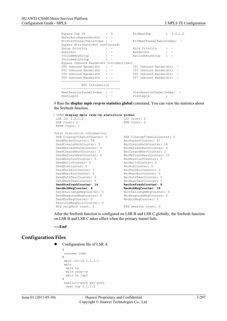
Bypass Lsp ID : 9 FrrNextHop : 3.3.1.2 ReferAutoBypassHandle : - FrrPrevTunnelTableIndex : - FrrNextTunnelTableIndex: - Bypass Attribute(Not configured) Setup Priority : - Hold Priority : - HopLimit : - Bandwidth : - IncludeAnyGroup : - ExcludeAnyGroup : - IncludeAllGroup : - Bypass Unbound Bandwidth Info(Kbit/sec) CT0 Unbound Bandwidth : - CT1 Unbound Bandwidth: - CT2 Unbound Bandwidth : - CT3 Unbound Bandwidth: - CT4 Unbound Bandwidth : - CT5 Unbound Bandwidth: - CT6 Unbound Bandwidth : - CT7 Unbound Bandwidth: - -------------------------------- BFD Information -------------------------------- NextSessionTunnelIndex : - PrevSessionTunnelIndex: - NextLspId : - PrevLspId : -
# Run the display mpls rsvp-te statistics global command. You can view the statistics aboutthe Srefresh function.[LSRB]display mpls rsvp-te statistics global LSR ID: 2.2.2.2 LSP Count: 2 PSB Count: 2 RSB Count: 2 RFSB Count: 1
Total Statistics Information: PSB CleanupTimeOutCounter: 0 RSB CleanupTimeOutCounter: 0 SendPacketCounter: 28 RecPacketCounter: 61 SendCreatePathCounter: 3 RecCreatePathCounter: 18 SendRefreshPathCounter: 9 RecRefreshPathCounter: 6 SendCreateResvCounter: 3 RecCreateResvCounter: 2 SendRefreshResvCounter: 4 RecRefreshResvCounter: 10 SendResvConfCounter: 0 RecResvConfCounter: 0 SendHelloCounter: 0 RecHelloCounter: 0 SendAckCounter: 0 RecAckCounter: 0 SendPathErrCounter: 1 RecPathErrCounter: 0 SendResvErrCounter: 0 RecResvErrCounter: 0 SendPathTearCounter: 0 RecPathTearCounter: 0 SendResvTearCounter: 0 RecResvTearCounter: 0 SendSrefreshCounter: 14 RecSrefreshCounter: 8 SendAckMsgCounter: 8 RecAckMsgCounter: 18 SendChallengeMsgCounter: 0 RecChallengeMsgCounter: 0 SendResponseMsgCounter: 0 RecResponseMsgCounter: 0 SendErrMsgCounter: 0 RecErrMsgCounter: 0 ResourceReqFaultCounter: 0 Bfd neighbor count: 2 Bfd session count: 0
After the Srefresh function is configured on LSR B and LSR C globally, the Srefresh functionon LSR B and LSR C takes effect when the primary tunnel fails.
----End
Configuration Filesl Configuration file of LSR A
# sysname LSRA# mpls lsr-id 1.1.1.1 mpls mpls te mpls rsvp-te mpls te cspf# explicit-path pri-path next hop 2.1.1.2
HUAWEI CX600 Metro Services PlatformConfiguration Guide - MPLS 3 MPLS TE Configuration
Issue 01 (2011-05-30) Huawei Proprietary and ConfidentialCopyright © Huawei Technologies Co., Ltd.
3-297
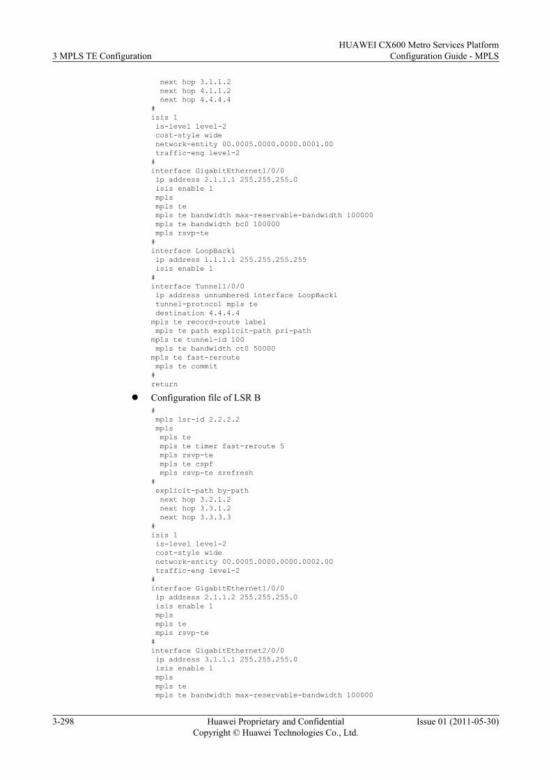
next hop 3.1.1.2 next hop 4.1.1.2 next hop 4.4.4.4#isis 1 is-level level-2 cost-style wide network-entity 00.0005.0000.0000.0001.00 traffic-eng level-2#interface GigabitEthernet1/0/0 ip address 2.1.1.1 255.255.255.0 isis enable 1 mpls mpls te mpls te bandwidth max-reservable-bandwidth 100000 mpls te bandwidth bc0 100000 mpls rsvp-te#interface LoopBack1 ip address 1.1.1.1 255.255.255.255 isis enable 1#interface Tunnel1/0/0 ip address unnumbered interface LoopBack1 tunnel-protocol mpls te destination 4.4.4.4mpls te record-route label mpls te path explicit-path pri-pathmpls te tunnel-id 100 mpls te bandwidth ct0 50000mpls te fast-reroute mpls te commit#return
l Configuration file of LSR B# mpls lsr-id 2.2.2.2 mpls mpls te mpls te timer fast-reroute 5 mpls rsvp-te mpls te cspf mpls rsvp-te srefresh# explicit-path by-path next hop 3.2.1.2 next hop 3.3.1.2 next hop 3.3.3.3#isis 1 is-level level-2 cost-style wide network-entity 00.0005.0000.0000.0002.00 traffic-eng level-2#interface GigabitEthernet1/0/0 ip address 2.1.1.2 255.255.255.0 isis enable 1 mpls mpls te mpls rsvp-te#interface GigabitEthernet2/0/0 ip address 3.1.1.1 255.255.255.0 isis enable 1 mpls mpls te mpls te bandwidth max-reservable-bandwidth 100000
3 MPLS TE ConfigurationHUAWEI CX600 Metro Services Platform
Configuration Guide - MPLS
3-298 Huawei Proprietary and ConfidentialCopyright © Huawei Technologies Co., Ltd.
Issue 01 (2011-05-30)
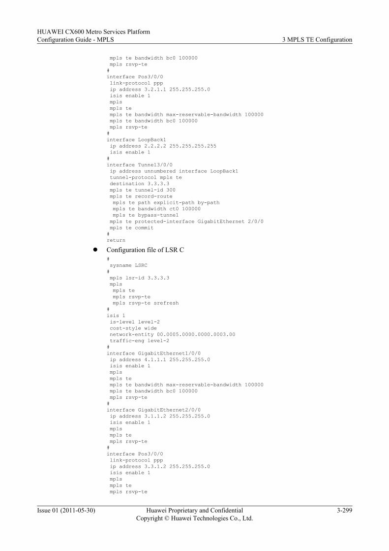
mpls te bandwidth bc0 100000 mpls rsvp-te#interface Pos3/0/0 link-protocol ppp ip address 3.2.1.1 255.255.255.0 isis enable 1 mpls mpls te mpls te bandwidth max-reservable-bandwidth 100000 mpls te bandwidth bc0 100000 mpls rsvp-te#interface LoopBack1 ip address 2.2.2.2 255.255.255.255 isis enable 1#interface Tunnel3/0/0 ip address unnumbered interface LoopBack1 tunnel-protocol mpls te destination 3.3.3.3 mpls te tunnel-id 300 mpls te record-route mpls te path explicit-path by-path mpls te bandwidth ct0 100000 mpls te bypass-tunnel mpls te protected-interface GigabitEthernet 2/0/0 mpls te commit#return
l Configuration file of LSR C# sysname LSRC# mpls lsr-id 3.3.3.3 mpls mpls te mpls rsvp-te mpls rsvp-te srefresh#isis 1 is-level level-2 cost-style wide network-entity 00.0005.0000.0000.0003.00 traffic-eng level-2#interface GigabitEthernet1/0/0 ip address 4.1.1.1 255.255.255.0 isis enable 1 mpls mpls te mpls te bandwidth max-reservable-bandwidth 100000 mpls te bandwidth bc0 100000 mpls rsvp-te#interface GigabitEthernet2/0/0 ip address 3.1.1.2 255.255.255.0 isis enable 1 mpls mpls te mpls rsvp-te#interface Pos3/0/0 link-protocol ppp ip address 3.3.1.2 255.255.255.0 isis enable 1 mpls mpls te mpls rsvp-te
HUAWEI CX600 Metro Services PlatformConfiguration Guide - MPLS 3 MPLS TE Configuration
Issue 01 (2011-05-30) Huawei Proprietary and ConfidentialCopyright © Huawei Technologies Co., Ltd.
3-299
#interface LoopBack1 ip address 3.3.3.3 255.255.255.255 isis enable 1#return
l Configuration file of LSR D# sysname LSRD# mpls lsr-id 4.4.4.4 mpls mpls te mpls rsvp-te#isis 1 is-level level-2 cost-style wide network-entity 00.0005.0000.0000.0004.00 traffic-eng level-2#interface GigabitEthernet1/0/0 ip address 4.1.1.2 255.255.255.0 isis enable 1 mpls mpls te mpls rsvp-te#interface LoopBack1 ip address 4.4.4.4 255.255.255.255 isis enable 1#return
l Configuration file of LSR E# sysname LSRE# mpls lsr-id 5.5.5.5 mpls mpls te mpls rsvp-te#isis 1 is-level level-2 cost-style wide network-entity 00.0005.0000.0000.0005.00 traffic-eng level-2#interface Pos1/0/0 link-protocol ppp clock master ip address 3.2.1.2 255.255.255.0 isis enable 1 mpls mpls te mpls rsvp-te#interface Pos2/0/0 link-protocol ppp clock master ip address 3.3.1.1 255.255.255.0 isis enable 1 mpls mpls te mpls te bandwidth max-reservable-bandwidth 100000 mpls te bandwidth bc0 100000 mpls rsvp-te#
3 MPLS TE ConfigurationHUAWEI CX600 Metro Services Platform
Configuration Guide - MPLS
3-300 Huawei Proprietary and ConfidentialCopyright © Huawei Technologies Co., Ltd.
Issue 01 (2011-05-30)
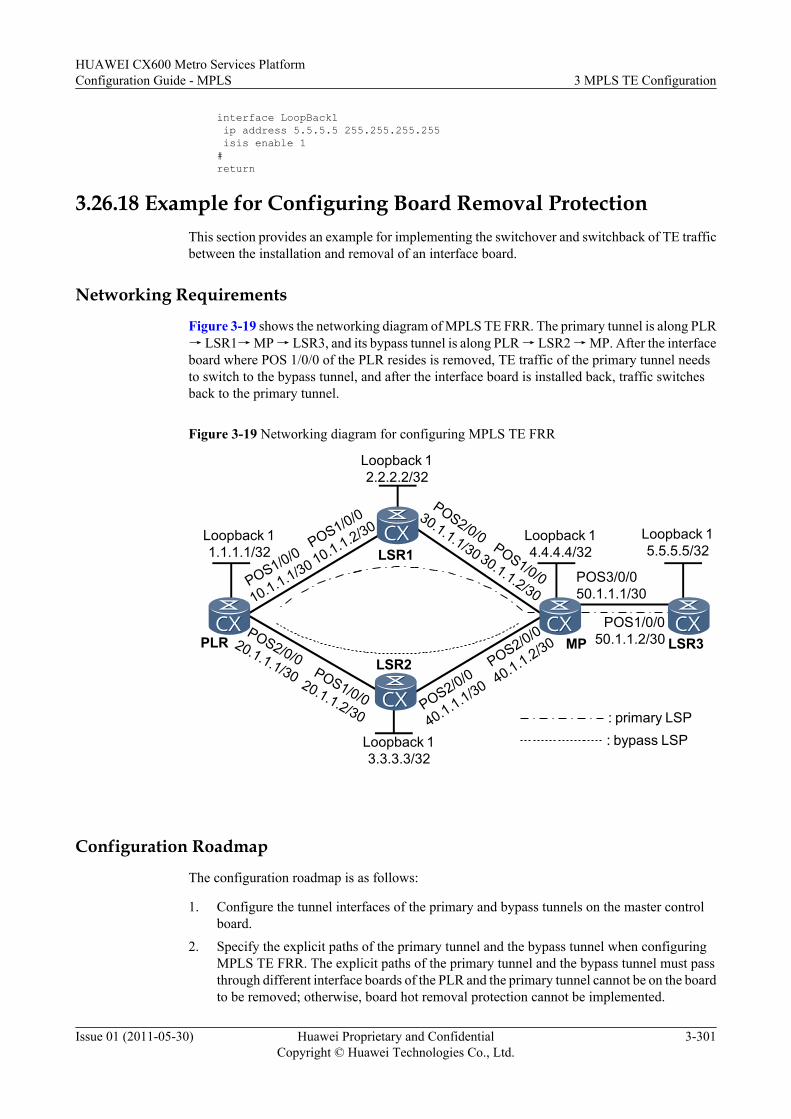
interface LoopBack1 ip address 5.5.5.5 255.255.255.255 isis enable 1#return
3.26.18 Example for Configuring Board Removal ProtectionThis section provides an example for implementing the switchover and switchback of TE trafficbetween the installation and removal of an interface board.
Networking Requirements
Figure 3-19 shows the networking diagram of MPLS TE FRR. The primary tunnel is along PLR→ LSR1→ MP → LSR3, and its bypass tunnel is along PLR → LSR2 → MP. After the interfaceboard where POS 1/0/0 of the PLR resides is removed, TE traffic of the primary tunnel needsto switch to the bypass tunnel, and after the interface board is installed back, traffic switchesback to the primary tunnel.
Figure 3-19 Networking diagram for configuring MPLS TE FRR
PLR
LSR1
MP LSR3LSR2
: primary LSP: bypass LSP
Loopback 11.1.1.1/32
POS1/0/0
10.1.1.1/30
POS2/0/020.1.1.1/30 POS1/0/0
20.1.1.2/30
POS1/0/0
10.1.1.2/30
POS2/0/0
40.1.1.1/30
POS2/0/030.1.1.1/30 POS1/0/0
30.1.1.2/30
POS2/0/0
40.1.1.2/30
POS3/0/050.1.1.1/30
POS1/0/050.1.1.2/30
Loopback 12.2.2.2/32
Loopback 14.4.4.4/32
Loopback 15.5.5.5/32
Loopback 13.3.3.3/32
Configuration Roadmap
The configuration roadmap is as follows:
1. Configure the tunnel interfaces of the primary and bypass tunnels on the master controlboard.
2. Specify the explicit paths of the primary tunnel and the bypass tunnel when configuringMPLS TE FRR. The explicit paths of the primary tunnel and the bypass tunnel must passthrough different interface boards of the PLR and the primary tunnel cannot be on the boardto be removed; otherwise, board hot removal protection cannot be implemented.
HUAWEI CX600 Metro Services PlatformConfiguration Guide - MPLS 3 MPLS TE Configuration
Issue 01 (2011-05-30) Huawei Proprietary and ConfidentialCopyright © Huawei Technologies Co., Ltd.
3-301
Data PreparationTo complete the configuration, you need the following data:
l Slot number of the main control board on the PLRl Tunnel interfaces of the primary and bypass tunnelsl Outgoing interfaces of the primary and bypass tunnelsl Explicit paths of the primary and bypass tunnels
ProcedureStep 1 Configure IP address on each interface.
The IP address and mask on each interface including the loopback interface are configured asshown in Figure 3-19. The detailed configuration is not provided here.
Step 2 Configure OSPF on all LSRs to advertise the routes of each network segment and the host routeof each LSR ID.
Configure OSPF on all LSRs to advertise the host route of each LSR ID. The detailedconfiguration is not provided here.
After the configuration, run the display ip routing-table command on each LSR. You can viewthat the LSRs learn the host route of the LSR ID from each other.
Step 3 Configure the basic MPLS functions and enable MPLS TE and RSVP-TE.
# Configure a PLR.[PLR] mpls lsr-id 1.1.1.1[PLR] mpls[PLR-mpls] mpls te[PLR-mpls] mpls rsvp-te[PLR-mpls] quit[PLR] interface pos 1/0/0[PLR-Pos1/0/0] mpls[PLR-Pos1/0/0] mpls te[PLR-Pos1/0/0] mpls rsvp-te[PLR-Pos1/0/0] quit[PLR] interface pos2/0/0[PLR-Pos2/0/0] mpls[PLR-Pos2/0/0] mpls te[PLR-Pos2/0/0] mpls rsvp-te[PLR-Pos2/0/0] quit
NOTE
The configurations on LSR1, LSR2, the MP, and LSR3 are similar to the configuration on the PLR, andare not provided here.
Step 4 Configure OSPF TE on all LSRs and enable CSPF on the ingress of the primary tunnel.
# Configure OSPF TE.[PLR] ospf[PLR-ospf-1] opaque-capability enable[PLR-ospf-1] area 0[PLR-ospf-1-area-0.0.0.0] mpls-te enable[PLR-ospf-1-area-0.0.0.0] quit[PLR-ospf-1] quit
NOTE
The configurations on LSR1, LSR2, the MP, and LSR3 are similar to the configuration on a PLR, and arenot provided here.
3 MPLS TE ConfigurationHUAWEI CX600 Metro Services Platform
Configuration Guide - MPLS
3-302 Huawei Proprietary and ConfidentialCopyright © Huawei Technologies Co., Ltd.
Issue 01 (2011-05-30)
# Enable CSPF on the ingress of the primary tunnel.
[PLR] mpls[PLR-mpls] mpls te cspf
Step 5 Configure the reservable bandwidth for the interfaces on each link.
Set the maximum reservable bandwidth of the link to 10 Mbit/s, the BC0 bandwidth to 10 Mbit/s, and the BC1 bandwidth to 3 Mbit/s.
# Configure the PLR.
[PLR] interface pos 1/0/0[PLR-Pos1/0/0] mpls te bandwidth max-reservable-bandwidth 10000[PLR-Pos1/0/0] mpls te bandwidth bc0 10000 bc1 3000[PLR-Pos1/0/0] quit[PLR] interface pos 2/0/0[PLR-Pos2/0/0] mpls te bandwidth max-reservable-bandwidth 10000[PLR-Pos2/0/0] mpls te bandwidth bc0 10000 bc1 3000[PLR-Pos2/0/0] quit
# Configure link bandwidth on all the outgoing interfaces of the link along the primary andbypass tunnels. The configurations are not provided here.
Step 6 Configure the primary tunnel.
# Configure the explicit path for the primary tunnel on the PLR.
[PLR] explicit-path master[PLR-explicit-path-master] next hop 10.1.1.2[PLR-explicit-path-master] next hop 30.1.1.2[PLR-explicit-path-master] next hop 50.1.1.2[PLR-explicit-path-master] next hop 5.5.5.5[PLR-explicit-path-master] quit
# Configure the tunnel interface of the primary tunnel.
[PLR] interface tunnel0/0/1[PLR-Tunnel0/0/1] ip address unnumbered interface loopback1[PLR-Tunnel0/0/1] tunnel-protocol mpls te[PLR-Tunnel0/0/1] destination 5.5.5.5[PLR-Tunnel0/0/1] mpls te tunnel-id 100[PLR-Tunnel0/0/1] mpls te signal-protocol rsvp-te[PLR-Tunnel0/0/1] mpls te path explicit-path master[PLR-Tunnel0/0/1] mpls te bandwidth ct0 400
# Enable MPLS TE FRR.
[PLR-Tunnel0/0/1] mpls te fast-reroute[PLR-Tunnel0/0/1] mpls te commit[PLR-Tunnel0/0/1] quit
# Run the display interface tunnel command on PLR. You can view the status of Tunnel 0/0/1of the primary tunnel is Up.
[PLR] display interface tunnel 0/0/1Tunnel0/0/1 current state : UPLine protocol current state : UPLast up time: 2009-03-29, 16:35:10Description : Tunnel0/0/1 Interface, Route Port...
Step 7 Configure the bypass tunnel.
# Configure the explicit path for the bypass tunnel on the PLR.
[PLR] explicit-path by-path[PLR-explicit-path-by-path] next hop 20.1.1.2
HUAWEI CX600 Metro Services PlatformConfiguration Guide - MPLS 3 MPLS TE Configuration
Issue 01 (2011-05-30) Huawei Proprietary and ConfidentialCopyright © Huawei Technologies Co., Ltd.
3-303
[PLR-explicit-path-by-path] next hop 40.1.1.2[PLR-explicit-path-by-path] next hop 4.4.4.4
# Configure the tunnel interface of the bypass tunnel.
[PLR] interface tunnel 0/0/2[PLR-Tunnel0/0/2] ip address unnumbered interface loopback 1[PLR-Tunnel0/0/2] tunnel-protocol mpls te[PLR-Tunnel0/0/2] destination 4.4.4.4[PLR-Tunnel0/0/2] mpls te tunnel-id 200[PLR-Tunnel0/0/2] mpls te signal-protocol rsvp-te[PLR-Tunnel0/0/2] mpls te path explicit-path by-path[PLR-Tunnel0/0/2] mpls te bypass-tunnel
# Configure the interface protected by the bypass tunnel.
[PLR-Tunnel0/0/2] mpls te protected-interface pos 1/0/0[PLR-Tunnel0/0/2] mpls te commit
# Run the display interface tunnel command on PLR. You can view the status of Tunnel 0/0/2of the bypass tunnel is Up.
<PLR> display interface tunnel 0/0/2Tunnel0/0/2 current state : UPLine protocol current state : UPLast up time: 2009-03-29, 16:43:34Description : Tunnel0/0/2 Interface, Route Port...
Step 8 Verify the configuration.
# Run the tracert lsp te tunnel command on the PLR. You can view TE traffic is transmittedthrough the primary tunnel.
<PLR> tracert lsp te tunnel 0/0/1 LSP Trace Route FEC: TE TUNNEL IPV4 SESSION QUERY Tunnel0/0/1 , press CTRL_C to break. TTL Replier Time Type Downstream 0 Ingress 10.1.1.2/[65536 ] 1 10.1.1.2 50 ms Transit 30.1.1.2/[131072 ] 2 30.1.1.2 40 ms Transit 50.1.1.2/[3 ] 3 5.5.5.5 70 ms Egress
# After the interface board where the outgoing interface of the primary tunnel (POS 1/0/0) residesis removed, run the display interface tunnel and display mpls te tunnel stale-interfaceinterface-index verbose commands. You can view that the tunnel interface of the primary tunnelremains Up.
# Run the display mpls te tunnel stale-interface command on the PLR. You can view that theoutgoing interface of the primary tunnel is in the Stale state.
<PLR> display mpls stale-interfaceStale-interface Status TE Attri LSP Count CRLSP Count Effective MTU0x018000106 Up Dis 0 1 -<PLR> display mpls te tunnel stale-interface 18000106 verbose No : 1 Tunnel-Name : Tunnel0/0/1 TunnelIndex : 0 LSP Index : 2048 Session ID : 100 LSP ID : 1 Lsr Role : Ingress LSP Type : - Ingress LSR ID : 1.1.1.1 Egress LSR ID : 5.5.5.5 In-Interface : - Out-Interface : 0x800086 Sign-Protocol : RSVP TE Resv Style : SE IncludeAnyAff : 0x0 ExcludeAnyAff : 0x0 IncludeAllAff : 0x0 LspConstraint : -
3 MPLS TE ConfigurationHUAWEI CX600 Metro Services Platform
Configuration Guide - MPLS
3-304 Huawei Proprietary and ConfidentialCopyright © Huawei Technologies Co., Ltd.
Issue 01 (2011-05-30)
ER-Hop Table Index : 0 AR-Hop Table Index: 5 C-Hop Table Index : 0 PrevTunnelIndexInSession: - NextTunnelIndexInSession: - PSB Handle : 1024 Created Time : 2009-03-29, 16:43:34 -------------------------------- DS-TE Information -------------------------------- Bandwidth Reserved Flag : Unreserved CT0 Bandwidth(Kbit/sec) : 0 CT1 Bandwidth(Kbit/sec): 0 CT2 Bandwidth(Kbit/sec) : 0 CT3 Bandwidth(Kbit/sec): 0 CT4 Bandwidth(Kbit/sec) : 0 CT5 Bandwidth(Kbit/sec): 0 CT6 Bandwidth(Kbit/sec) : 0 CT7 Bandwidth(Kbit/sec): 0 Setup-Priority : 7 Hold-Priority : 7 -------------------------------- FRR Information -------------------------------- Primary LSP Info TE Attribute Flag : 0x63 Protected Flag : 0x1 Bypass In Use : In Use Bypass Tunnel Id : 8396808 BypassTunnel : Tunnel Index[Tunnel0/0/2], InnerLabel[65536] Bypass Lsp ID : 1 FrrNextHop : 40.1.1.2 ReferAutoBypassHandle : - FrrPrevTunnelTableIndex : - FrrNextTunnelTableIndex: - Bypass Attribute(Not configured) Setup Priority : - Hold Priority : - HopLimit : - Bandwidth : - IncludeAnyGroup : - ExcludeAnyGroup : - IncludeAllGroup : - Bypass Unbound Bandwidth Info(Kbit/sec) CT0 Unbound Bandwidth : - CT1 Unbound Bandwidth: - CT2 Unbound Bandwidth : - CT3 Unbound Bandwidth: - CT4 Unbound Bandwidth : - CT5 Unbound Bandwidth: - CT6 Unbound Bandwidth : - CT7 Unbound Bandwidth: - -------------------------------- BFD Information -------------------------------- NextSessionTunnelIndex : - PrevSessionTunnelIndex: - NextLspId : - PrevLspId : -
# Run the display mpls te tunnel path command on the PLR. You can view the path informationof the primary tunnel.
<PLR> display mpls te tunnel path Tunnel0/0/1Tunnel Interface Name : Tunnel0/0/1 Lsp ID : 1.1.1.1 :100 :1 Hop Information Hop 0 20.1.1.1 Local-Protection in use Hop 1 20.1.1.2 Label 65536 Hop 2 3.3.3.3 Label 65536 Hop 3 40.1.1.1 Hop 4 40.1.1.2 Label 131072 Hop 5 4.4.4.4 Label 131072 Hop 6 50.1.1.1 Hop 7 50.1.1.2 Label 3 Hop 8 5.5.5.5 Label 3
# Run the tracert lsp te tunnel command. You can view TE traffic is transmitted through thebypass tunnel.
<PLR> tracert lsp te tunnel 0/0/1 LSP Trace Route FEC: TE TUNNEL IPV4 SESSION QUERY Tunnel0/0/1 , press CTRL_C to break. TTL Replier Time Type Downstream 0 Ingress 20.1.1.2/[65536 15360 ] 1 20.1.1.2 50 ms Transit 40.1.1.2/[131073 ] 2 40.1.1.2 50 ms Transit 30.1.1.1/[3 ] 3 30.1.1.1 4 ms Transit
HUAWEI CX600 Metro Services PlatformConfiguration Guide - MPLS 3 MPLS TE Configuration
Issue 01 (2011-05-30) Huawei Proprietary and ConfidentialCopyright © Huawei Technologies Co., Ltd.
3-305
4 30.1.1.2 15 ms Transit 50.1.1.2/[3 ] 5 11.1.1.1 6 ms Egress
# After the interface board where the outgoing interface of the primary tunnel resides is re-plugged in, run the tracert lsp te tunnel command. You can view that traffic switches back tothe primary tunnel.
<PLR> tracert lsp te tunnel 0/0/1 LSP Trace Route FEC: TE TUNNEL IPV4 SESSION QUERY Tunnel6/0/0 , press CTRL_C to break. TTL Replier Time Type Downstream 0 Ingress 10.1.1.2/[65537 ] 1 10.1.1.2 40 ms Transit 30.1.1.2/[131074 ] 2 30.1.1.2 50 ms Transit 50.1.1.2/[3 ] 3 5.5.5.5 60 ms Egress
----End
Configuration Filesl Configuration file of the PLR
# sysname PLR# mpls lsr-id 1.1.1.1 mpls mpls te mpls rsvp-te mpls te cspf# explicit-path master next hop 10.1.1.2 next hop 30.1.1.2 next hop 50.1.1.2 next hop 5.5.5.5# explicit-path by-path next hop 20.1.1.2 next hop 40.1.1.2 next hop 4.4.4.4#interface Pos1/0/0 link-protocol ppp ip address 10.1.1.1 255.255.255.252 mpls mpls te mpls te bandwidth max-reservable-bandwidth 10000 mpls te bandwidth bc0 10000 bc1 3000 mpls rsvp-te#interface Pos2/0/0 link-protocol ppp ip address 20.1.1.1 255.255.255.252 mpls mpls te mpls te bandwidth max-reservable-bandwidth 10000 mpls te bandwidth bc0 10000 bc1 3000 mpls rsvp-te#interface LoopBack1 ip address 1.1.1.1 255.255.255.255#interface Tunnel0/0/1 ip address unnumbered interface LoopBack1 tunnel-protocol mpls te destination 5.5.5.5 mpls te tunnel-id 100 mpls te bandwidth ct0 400
3 MPLS TE ConfigurationHUAWEI CX600 Metro Services Platform
Configuration Guide - MPLS
3-306 Huawei Proprietary and ConfidentialCopyright © Huawei Technologies Co., Ltd.
Issue 01 (2011-05-30)
mpls te path explicit-path master mpls te fast-reroute mpls te commit#interface Tunnel0/0/2 ip address unnumbered interface LoopBack1 tunnel-protocol mpls te destination 4.4.4.4 mpls te tunnel-id 200 mpls te record-route mpls te path explicit-path by-path mpls te bypass-tunnel mpls te protected-interface Pos1/0/0 mpls te commit#ospf 1 opaque-capability enable area 0.0.0.0 network 10.1.1.0 0.0.0.3 network 20.1.1.0 0.0.0.3 network 1.1.1.1 0.0.0.0 mpls-te enable#return
l Configuration file of LSR1# sysname LSR1# mpls lsr-id 2.2.2.2 mpls mpls te mpls rsvp-te# interface Pos1/0/0 link-protocol ppp ip address 10.1.1.2 255.255.255.252 mpls mpls te mpls rsvp-te#interface Pos2/0/0 link-protocol ppp ip address 30.1.1.1 255.255.255.252 mpls mpls te mpls te bandwidth max-reservable-bandwidth 10000 mpls te bandwidth bc0 10000 bc1 3000 mpls rsvp-te#interface LoopBack1 ip address 2.2.2.2 255.255.255.255# ospf 1 opaque-capability enable area 0.0.0.0 network 10.1.1.0 0.0.0.3 network 30.1.1.0 0.0.0.3 network 2.2.2.2 0.0.0.0 mpls-te enable#return
l Configuration file of LSR2# sysname LSR2# mpls lsr-id 3.3.3.3 mpls mpls te
HUAWEI CX600 Metro Services PlatformConfiguration Guide - MPLS 3 MPLS TE Configuration
Issue 01 (2011-05-30) Huawei Proprietary and ConfidentialCopyright © Huawei Technologies Co., Ltd.
3-307
mpls rsvp-te#interface Pos1/0/0 link-protocol ppp ip address 20.1.1.2 255.255.255.252 mpls mpls te mpls rsvp-te#interface Pos2/0/0 link-protocol ppp ip address 40.1.1.1 255.255.255.252 mpls mpls te mpls te bandwidth max-reservable-bandwidth 10000 mpls te bandwidth bc0 10000 bc1 3000 mpls rsvp-te#interface LoopBack1 ip address 3.3.3.3 255.255.255.255#ospf 1 opaque-capability enable area 0.0.0.0 network 20.1.1.0 0.0.0.3 network 30.1.1.0 0.0.0.3 network 3.3.3.3 0.0.0.0 mpls-te enable#return
l Configuration file of the MP# sysname MP# mpls lsr-id 4.4.4.4 mpls mpls te mpls rsvp-te# interface Pos1/0/0 link-protocol ppp ip address 30.1.1.2 255.255.255.252 mpls mpls te mpls rsvp-te#interface Pos2/0/0 link-protocol ppp ip address 40.1.1.2 255.255.255.252 mpls mpls te mpls rsvp-te#interface Pos3/0/0 link-protocol ppp ip address 50.1.1.1 255.255.255.252 mpls mpls te mpls te bandwidth max-reservable-bandwidth 10000 mpls te bandwidth bc0 10000 bc1 3000 mpls rsvp-te#interface LoopBack1 ip address 4.4.4.4 255.255.255.255# ospf 1 opaque-capability enable area 0.0.0.0 network 30.1.1.0 0.0.0.3
3 MPLS TE ConfigurationHUAWEI CX600 Metro Services Platform
Configuration Guide - MPLS
3-308 Huawei Proprietary and ConfidentialCopyright © Huawei Technologies Co., Ltd.
Issue 01 (2011-05-30)
network 40.1.1.0 0.0.0.3 network 50.1.1.0 0.0.0.3 network 4.4.4.4 0.0.0.0 mpls-te enable#return
l Configuration file of LSR3# sysname LSR3# mpls lsr-id 5.5.5.5 mpls mpls te mpls rsvp-te#interface Pos1/0/0 link-protocol ppp ip address 50.1.1.2 255.255.255.252 mpls mpls te mpls rsvp-te#interface LoopBack1 ip address 5.5.5.5 255.255.255.255#ospf 1 opaque-capability enable area 0.0.0.0 network 50.1.1.0 0.0.0.3 network 5.5.5.5 0.0.0.0 mpls-te enable#return
3.26.19 Example for Configuring CR-LSP Hot StandbyThis section provides an example for establishing a hot-standby CR-LSP, including configuringa hot-standby CR-LSP and a best-effort CR-LSP.
Networking RequirementsFigure 3-20 shows an MPLS VPN. A TE tunnel from PE1 functioning as the ingress to PE2functioning as the egress, CR-LSP hot backup, and best-effort LSPs need to be configured. Thefollowing LSPs need to be established:
l Primary CR-LSP along PE1 --> P1 --> PE2l Backup CR-LSP along PE1 --> P2 --> PE2l Best-effort LSP along PE1 --> P2 --> P1 --> PE2
If the primary CR-LSP fails, traffic switches to the backup CR-LSP. After the primary CR-LSPrecovers from the fault, traffic switches back to the primary CR-LSP in 15 seconds. If both theprimary CR-LSP and backup CR-LSP fail, traffic switches to the best-effort LSP.
HUAWEI CX600 Metro Services PlatformConfiguration Guide - MPLS 3 MPLS TE Configuration
Issue 01 (2011-05-30) Huawei Proprietary and ConfidentialCopyright © Huawei Technologies Co., Ltd.
3-309
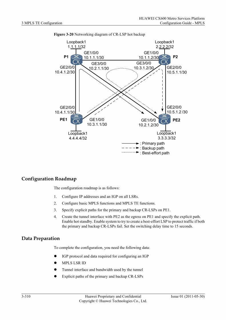
Figure 3-20 Networking diagram of CR-LSP hot backup
Loopback11.1.1.1/32
Loopback12.2.2.2/32
Loopback14.4.4.4/32
Loopback13.3.3.3/32
GE2/0/010.4.1.1/30
GE2/0/010.4.1.2/30
GE1/0/010.1.1.1/30
GE1/0/010.1.1.2/30
GE3/0/010.3.1.2/30 GE2/0/0
10.5.1.1/30
GE2/0/010.5.1.2 /30
GE1/0/010.2.1.2/30
GE3/0/010.2.1.1/30
GE1/0/010.3.1.1/30
: Primary path: Backup path: Best-effort path
PE1 PE2
P1 P2
Configuration Roadmap
The configuration roadmap is as follows:
1. Configure IP addresses and an IGP on all LSRs.
2. Configure basic MPLS functions and MPLS TE functions.
3. Specify explicit paths for the primary and backup CR-LSPs on PE1.
4. Create the tunnel interface with PE2 as the egress on PE1 and specify the explicit path.Enable hot standby. Enable system to try to create a best-effort LSP to protect traffic if boththe primary and backup CR-LSPs fail. Set the switching delay time to 15 seconds.
Data Preparation
To complete the configuration, you need the following data:
l IGP protocol and data required for configuring an IGP
l MPLS LSR ID
l Tunnel interface and bandwidth used by the tunnel
l Explicit paths of the primary and backup CR-LSPs
3 MPLS TE ConfigurationHUAWEI CX600 Metro Services Platform
Configuration Guide - MPLS
3-310 Huawei Proprietary and ConfidentialCopyright © Huawei Technologies Co., Ltd.
Issue 01 (2011-05-30)
Procedure
Step 1 Configure an IP address for each interface.
Configure an IP address for each interface, create loopback interfaces on LSRs, and thenconfigure the IP addresses of loopback interfaces as MPLS LSR IDs as shown in Figure 3-20.For detailed configuration, see configuration files in this example.
Step 2 Configure an IGP.
Configure OSPF or IS-IS on each LSR to enable communication between LSRs. In this example,IS-IS is configured. For detailed configuration, see configuration files in this example.
Step 3 Configure basic MPLS functions.
On each LSR, configure an LSR ID and enable MPLS in the system view and in the interfaceview. For detailed configuration, see configuration files in this example.
Step 4 Configure basic MPLS TE functions.
Enable MPLS-TE and MPLS RSVP-TE in the MPLS view and the interface view on each LSR.Set the maximum reservable bandwidth of links to 100 Mbit/s and the bandwidth of BC0 to 100Mbit/s. For detailed configurations, see configuration files in this example.
Step 5 Configure IS-IS TE and CSPF.
Configure IS-IS TE on each LSR and CSPF on PE1. For detailed configuration, see configurationfiles in this example.
Step 6 Configure the explicit paths for the primary and backup CR-LSPs respectively.
# Configure the explicit path for the primary CR-LSP on PE1.
<PE1> system-view[PE1] explicit-path main[PE1-explicit-path-main] next hop 10.4.1.2[PE1-explicit-path-main] next hop 10.2.1.2[PE1-explicit-path-main] next hop 3.3.3.3[PE1-explicit-path-main] quit
# Configure the explicit path for the backup CR-LSP on PE1.
[PE1] explicit-path backup[PE1-explicit-path-backup] next hop 10.3.1.2[PE1-explicit-path-backup] next hop 10.5.1.2[PE1-explicit-path-backup] next hop 3.3.3.3[PE1-explicit-path-backup] quit
# Display information about the explicit path on PE1.
[PE1] display explicit-path mainPath Name : main Path Status : Enabled 1 10.4.1.2 Strict Include 2 10.2.1.2 Strict Include 3 3.3.3.3 Strict Include[PE1] display explicit-path backupPath Name : backup Path Status : Enabled 1 10.3.1.2 Strict Include 2 10.5.1.2 Strict Include 3 3.3.3.3 Strict Include
Step 7 Configure the tunnel interfaces.
# Configure a Tunnel interface on PE1; specify the explicit path; set the tunnel bandwidth to 10Mbit/s.
HUAWEI CX600 Metro Services PlatformConfiguration Guide - MPLS 3 MPLS TE Configuration
Issue 01 (2011-05-30) Huawei Proprietary and ConfidentialCopyright © Huawei Technologies Co., Ltd.
3-311
[PE1] interface tunnel 1/0/0[PE1-Tunnel1/0/0] ip address unnumbered interface loopback 1[PE1-Tunnel1/0/0] tunnel-protocol mpls te[PE1-Tunnel1/0/0] destination 3.3.3.3[PE1-Tunnel1/0/0] mpls te tunnel-id 100[PE1-Tunnel1/0/0] mpls te path explicit-path main[PE1-Tunnel1/0/0] mpls te bandwidth ct0 10000
# Configure hot standby on the tunnel interface, configure the switch delay time to 15 seconds,specify the explicit path, and configure the best-effort LSP.
[PE1-Tunnel1/0/0] mpls te backup hot-standby wtr 15[PE1-Tunnel1/0/0] mpls te path explicit-path backup secondary[PE1-Tunnel1/0/0] mpls te backup ordinary best-effort[PE1-Tunnel1/0/0] mpls te commit[PE1-Tunnel1/0/0] quit
Run the display mpls te tunnel-interface tunnel 1/0/0 command on PE1. You can see that theprimary and backup CR-LSPs have been established.
[PE1] display mpls te tunnel-interface tunnel 1/0/0 ================================================================ Tunnel1/0/0 ================================================================ Tunnel State Desc : UP Active LSP : Primary LSP Session ID : 100 Ingress LSR ID : 4.4.4.4 Egress LSR ID: 3.3.3.3 Admin State : UP Oper State : UP Primary LSP State : UP Main LSP State : READY LSP ID : 1 Hot-Standby LSP State : UP Main LSP State : READY LSP ID : 32770
# Display information about hot backup.
[PE1] display mpls te hot-standby state interface Tunnel 1/0/0----------------------------------------------------------------Verbose information about the Tunnel1/0/0 hot-standby state----------------------------------------------------------------session id : 100main LSP token : 0x100201ahot-standby LSP token : 0x100201bHSB switch result : Primary LSPWTR : 15susing same path : no
# Run the ping lsp te command to check the connection of the backup CR-LSP.[PE1] ping lsp te tunnel 1/0/0 hot-standby LSP PING FEC: TE TUNNEL IPV4 SESSION QUERY Tunnel1/0/0 : 100 data bytes, press CTRL_C to break Reply from 3.3.3.3: bytes=100 Sequence=1 time = 380 ms Reply from 3.3.3.3: bytes=100 Sequence=2 time = 130 ms Reply from 3.3.3.3: bytes=100 Sequence=3 time = 70 ms Reply from 3.3.3.3: bytes=100 Sequence=4 time = 120 ms Reply from 3.3.3.3: bytes=100 Sequence=5 time = 120 ms
--- FEC: TE TUNNEL IPV4 SESSION QUERY Tunnel1/0/0 ping statistics --- 5 packet(s) transmitted 5 packet(s) received 0.00% packet loss round-trip min/avg/max = 70/164/380 ms
# Run the tracert lsp te command to trace the path of the backup CR-LSP.[PE1] tracert lsp te tunnel 1/0/0 hot-standby LSP Trace Route FEC: TE TUNNEL IPV4 SESSION QUERY Tunnel1/0/0 , press CTRL_C to break. TTL Replier Time Type Downstream 0 Ingress 10.3.1.2/[13313 ]
3 MPLS TE ConfigurationHUAWEI CX600 Metro Services Platform
Configuration Guide - MPLS
3-312 Huawei Proprietary and ConfidentialCopyright © Huawei Technologies Co., Ltd.
Issue 01 (2011-05-30)
1 10.3.1.2 90 ms Transit 10.5.1.2/[3 ] 2 3.3.3.3 130 ms Egress
Step 8 Verify the configuration.
Connect two interfaces, Port 1 and Port 2, on a tester to PE1 and PE2 respectively. On Port 1,inject MPLS traffic and send traffic to Port 2. After the cable attached to GE 2/0/0 on PE1 or P1is pulled out, fault recovery is performed at millisecond level. Run the display mpls te hot-standby state interface tunnel 1/0/0 command on PE1. You can see that traffic has switchedto the backup CR-LSP.
[PE1] display mpls te hot-standby state interface tunnel 1/0/0----------------------------------------------------------------Verbose information about the Tunnel1/0/0 hot-standby state----------------------------------------------------------------session id : 100main LSP token : 0x0hot-standby LSP token : 0x100201bHSB switch result : Hot-standby LSPWTR : 15susing same path : no
After attaching the cable into GE 2/0/0, you can see that traffic switches back to the primaryCR-LSP in 15 seconds.
After you remove the cable from GE 2/0/0 on PE1 or P1 and the cable from GE 2/0/0 on PE2or P2, the tunnel interface goes Down and then Up. This means that the best-effort has been setup successfully, allowing traffic to switch to the best-effort LSP.
[PE1] display mpls te tunnel-interface tunnel 1/0/0 ================================================================ Tunnel1/0/0 ================================================================ Tunnel State Desc : UP Active LSP : Best-Effort LSP Session ID : 100 Ingress LSR ID : 4.4.4.4 Egress LSR ID: 3.3.3.3 Admin State : UP Oper State : UP Primary LSP State : DOWN Main LSP State : SETTING UP Hot-Standby LSP State : DOWN Main LSP State : SETTING UP Best-Effort LSP State : UP Main LSP State : READY LSP ID : 32773[PE1] display mpls te tunnel path Tunnel Interface Name : Tunnel1/0/0 Lsp ID : 4.4.4.4 :100 :32776 Hop Information Hop 0 10.3.1.1 Hop 1 10.3.1.2 Hop 2 2.2.2.2 Hop 3 10.1.1.2 Hop 4 10.1.1.1 Hop 5 1.1.1.1 Hop 6 10.2.1.1 Hop 7 10.2.1.2 Hop 8 3.3.3.3
----End
Configuration Filesl Configuration file of PE1
# sysname PE1#
HUAWEI CX600 Metro Services PlatformConfiguration Guide - MPLS 3 MPLS TE Configuration
Issue 01 (2011-05-30) Huawei Proprietary and ConfidentialCopyright © Huawei Technologies Co., Ltd.
3-313
mpls lsr-id 4.4.4.4 mpls mpls te mpls rsvp-te mpls te cspf# explicit-path backup next hop 10.3.1.2 next hop 10.5.1.2 next hop 3.3.3.3# explicit-path main next hop 10.4.1.2 next hop 10.2.1.2 next hop 3.3.3.3#isis 1 cost-style wide network-entity 10.0000.0000.0004.00 traffic-eng level-1-2#interface GigabitEthernet1/0/0 ip address 10.3.1.1 255.255.255.252 isis enable 1 mpls mpls te mpls te bandwidth max-reservable-bandwidth 100000 mpls te bandwidth bc0 100000 bc1 50000 mpls rsvp-te#interface GigabitEthernet2/0/0 ip address 10.4.1.1 255.255.255.252 isis enable 1 mpls mpls te mpls te bandwidth max-reservable-bandwidth 100000 mpls te bandwidth bc0 100000 bc1 50000 mpls rsvp-te#interface LoopBack1 ip address 4.4.4.4 255.255.255.255 isis enable 1#interface Tunnel1/0/0 ip address unnumbered interface LoopBack1 tunnel-protocol mpls te destination 3.3.3.3 mpls te tunnel-id 100 mpls te record-route mpls te bandwidth ct0 10000 mpls te path explicit-path main mpls te path explicit-path backup secondary mpls te backup hot-standby wtr 15 mpls te backup ordinary best-effort mpls te commit#return
l Configuration file of P1# sysname P1# mpls lsr-id 1.1.1.1 mpls mpls te mpls rsvp-te#isis 1 cost-style wide network-entity 10.0000.0000.0001.00
3 MPLS TE ConfigurationHUAWEI CX600 Metro Services Platform
Configuration Guide - MPLS
3-314 Huawei Proprietary and ConfidentialCopyright © Huawei Technologies Co., Ltd.
Issue 01 (2011-05-30)
traffic-eng level-1-2#interface GigabitEthernet1/0/0 ip address 10.1.1.1 255.255.255.252 isis enable 1 mpls mpls te mpls rsvp-te#interface GigabitEthernet2/0/0 ip address 10.4.1.2 255.255.255.252 isis enable 1 mpls mpls te mpls rsvp-te#interface GigabitEthernet3/0/0 ip address 10.2.1.1 255.255.255.252 isis enable 1 mpls mpls te mpls te bandwidth max-reservable-bandwidth 100000 mpls te bandwidth bc0 100000 bc1 50000 mpls rsvp-te#interface LoopBack1 ip address 1.1.1.1 255.255.255.255 isis enable 1#return
l Configuration file of P2# sysname P2# mpls lsr-id 2.2.2.2 mpls mpls te mpls rsvp-te#isis 1 cost-style wide network-entity 10.0000.0000.0002.00 traffic-eng level-1-2#interface GigabitEthernet1/0/0 ip address 10.1.1.2 255.255.255.252 isis enable 1 mpls mpls te mpls te bandwidth max-reservable-bandwidth 100000 mpls te bandwidth bc0 100000 bc1 50000 mpls rsvp-te#interface GigabitEthernet2/0/0 ip address 10.5.1.1 255.255.255.252 isis enable 1 mpls mpls te mpls te bandwidth max-reservable-bandwidth 100000 mpls te bandwidth bc0 100000 bc1 50000 mpls rsvp-te#interface GigabitEthernet3/0/0 ip address 10.3.1.2 255.255.255.252 isis enable 1 mpls mpls te mpls rsvp-te#
HUAWEI CX600 Metro Services PlatformConfiguration Guide - MPLS 3 MPLS TE Configuration
Issue 01 (2011-05-30) Huawei Proprietary and ConfidentialCopyright © Huawei Technologies Co., Ltd.
3-315
interface LoopBack1 ip address 2.2.2.2 255.255.255.255 isis enable 1#return
l Configuration file of PE2# sysname PE2# mpls lsr-id 3.3.3.3 mpls mpls te mpls rsvp-te#isis 1 cost-style wide network-entity 10.0000.0000.0003.00 traffic-eng level-1-2#interface GigabitEthernet1/0/0 ip address 10.2.1.2 255.255.255.252 isis enable 1 mpls mpls te mpls rsvp-te#interface GigabitEthernet2/0/0 ip address 10.5.1.2 255.255.255.252 isis enable 1 mpls mpls te mpls rsvp-te#interface LoopBack1 ip address 3.3.3.3 255.255.255.255 isis enable 1#return
3.26.20 Example for Locking an Attribute Template for Hot-standbyCR-LSPs
This section describes how to lock an attribute template for hot-standby CR-LSPs. You canconfigure an attribute template for hot-standby CR-LSPs, preventing an unwanted CR-LSPswitchover and reducing resource consumption.
Networking RequirementsOn a network as shown in Figure 3-21, a primary CR-LSP needs to be set up from LSR A toLSR D, and a hot-standby CR-LSP needs to be set up for the primary CR-LSP.
A maximum of three attribute templates can be created for a backup CR-LSP. In the event thata CR-LSP established using any of the three templates is stable, you can lock a CR-LSP attributetemplate, thus avoiding unnecessary traffic switchover and reducing consumption of systemresources.
When an attribute template for hot-standby CR-LSPs is locked, the following effects can beachieved:
l If a hot-standby CR-LSP is established through a lower-priority attribute template, thesystem will not use a higher-priority attribute template to create a new hot-standby CR-LSP.
3 MPLS TE ConfigurationHUAWEI CX600 Metro Services Platform
Configuration Guide - MPLS
3-316 Huawei Proprietary and ConfidentialCopyright © Huawei Technologies Co., Ltd.
Issue 01 (2011-05-30)
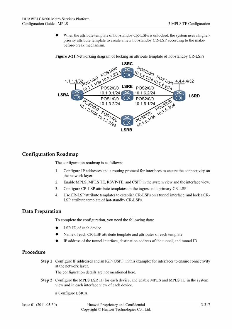
l When the attribute template of hot-standby CR-LSPs is unlocked, the system uses a higher-priority attribute template to create a new hot-standby CR-LSP according to the make-before-break mechanism.
Figure 3-21 Networking diagram of locking an attribute template of hot-standby CR-LSPs
POS2/0/010.1.6.2/24
1.1.1.1/32 4.4.4.4/32
POS2/0/0
10.1.5.1/24
POS1/0/0
10.1.1.1/24POS2/0/0
10.1.3.1/24
POS3/0/010.1.2.1/24 POS1/0/0
10.1.2.2/24
POS3/0/0
10.1.5.2/24POS1/0/0
10.1.3.2/24POS2/0/0
10.1.6.1/24
POS1/0/0
10.1.1.2/24POS2/0/010.1.4.1/24 POS1/0/010.1.4.2/24
LSRA
LSRC
LSRD
LSRB
LSRE
Configuration RoadmapThe configuration roadmap is as follows:
1. Configure IP addresses and a routing protocol for interfaces to ensure the connectivity onthe network layer.
2. Enable MPLS, MPLS TE, RSVP-TE, and CSPF in the system view and the interface view.3. Configure CR-LSP attribute templates on the ingress of a primary CR-LSP.4. Use CR-LSP attribute templates to establish CR-LSPs on a tunnel interface, and lock a CR-
LSP attribute template of hot-standby CR-LSPs.
Data PreparationTo complete the configuration, you need the following data:
l LSR ID of each devicel Name of each CR-LSP attribute template and attributes of each templatel IP address of the tunnel interface, destination address of the tunnel, and tunnel ID
Procedure
Step 1 Configure IP addresses and an IGP (OSPF, in this example) for interfaces to ensure connectivityat the network layer.The configuration details are not mentioned here.
Step 2 Configure the MPLS LSR ID for each device, and enable MPLS and MPLS TE in the systemview and in each interface view of each device.
# Configure LSR A.
HUAWEI CX600 Metro Services PlatformConfiguration Guide - MPLS 3 MPLS TE Configuration
Issue 01 (2011-05-30) Huawei Proprietary and ConfidentialCopyright © Huawei Technologies Co., Ltd.
3-317
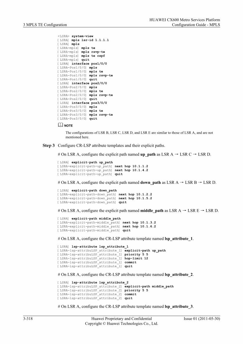
<LSRA> system-view[LSRA] mpls lsr-id 1.1.1.1[LSRA] mpls [LSRA-mpls] mpls te[LSRA-mpls] mpls rsvp-te[LSRA-mpls] mpls te cspf[LSRA-mpls] quit[LSRA] interface pos1/0/0[LSRA-Pos1/0/0] mpls[LSRA-Pos1/0/0] mpls te[LSRA-Pos1/0/0] mpls rsvp-te[LSRA-Pos1/0/0] quit[LSRA] interface pos2/0/0[LSRA-Pos2/0/0] mpls[LSRA-Pos2/0/0] mpls te[LSRA-Pos2/0/0] mpls rsvp-te[LSRA-Pos2/0/0] quit[LSRA] interface pos3/0/0[LSRA-Pos3/0/0] mpls[LSRA-Pos3/0/0] mpls te[LSRA-Pos3/0/0] mpls rsvp-te[LSRA-Pos3/0/0] quit
NOTE
The configurations of LSR B, LSR C, LSR D, and LSR E are similar to those of LSR A, and are notmentioned here.
Step 3 Configure CR-LSP attribute templates and their explicit paths.
# On LSR A, configure the explicit path named up_path as LSR A → LSR C → LSR D.
[LSRA] explicit-path up_path[LSRA-explicit-path-up_path] next hop 10.1.1.2[LSRA-explicit-path-up_path] next hop 10.1.4.2[LSRA-explicit-path-up_path] quit
# On LSR A, configure the explicit path named down_path as LSR A → LSR B → LSR D.
[LSRA] explicit-path down_path[LSRA-explicit-path-down_path] next hop 10.1.2.2[LSRA-explicit-path-down_path] next hop 10.1.5.2[LSRA-explicit-path-down_path] quit
# On LSR A, configure the explicit path named middle_path as LSR A → LSR E → LSR D.
[LSRA] explicit-path middle_path[LSRA-explicit-path-middle_path] next hop 10.1.3.2[LSRA-explicit-path-middle_path] next hop 10.1.6.2[LSRA-explicit-path-middle_path] quit
# On LSR A, configure the CR-LSP attribute template named lsp_attribute_1.
[LSRA] lsp-attribute lsp_attribute_1[LSRA-lsp-attribuLSP_attribute_1] explicit-path up_path[LSRA-lsp-attribuLSP_attribute_1] priority 5 5[LSRA-lsp-attribuLSP_attribute_1] hop-limit 12[LSRA-lsp-attribuLSP_attribute_1] commit[LSRA-lsp-attribuLSP_attribute_1] quit
# On LSR A, configure the CR-LSP attribute template named lsp_attribute_2.
[LSRA] lsp-attribute lsp_attribute_2[LSRA-lsp-attribuLSP_attribute_2] explicit-path middle_path[LSRA-lsp-attribuLSP_attribute_2] priority 5 5[LSRA-lsp-attribuLSP_attribute_2] commit[LSRA-lsp-attribuLSP_attribute_2] quit
# On LSR A, configure the CR-LSP attribute template named lsp_attribute_3.
3 MPLS TE ConfigurationHUAWEI CX600 Metro Services Platform
Configuration Guide - MPLS
3-318 Huawei Proprietary and ConfidentialCopyright © Huawei Technologies Co., Ltd.
Issue 01 (2011-05-30)
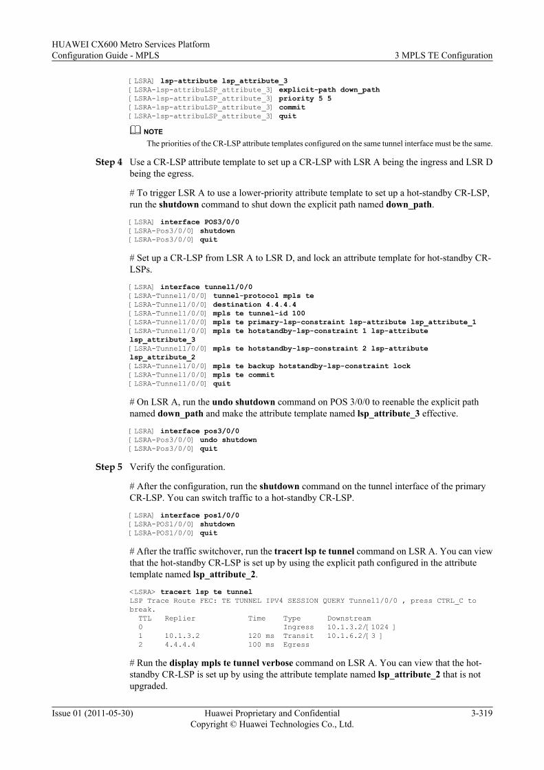
[LSRA] lsp-attribute lsp_attribute_3[LSRA-lsp-attribuLSP_attribute_3] explicit-path down_path[LSRA-lsp-attribuLSP_attribute_3] priority 5 5[LSRA-lsp-attribuLSP_attribute_3] commit[LSRA-lsp-attribuLSP_attribute_3] quit
NOTEThe priorities of the CR-LSP attribute templates configured on the same tunnel interface must be the same.
Step 4 Use a CR-LSP attribute template to set up a CR-LSP with LSR A being the ingress and LSR Dbeing the egress.
# To trigger LSR A to use a lower-priority attribute template to set up a hot-standby CR-LSP,run the shutdown command to shut down the explicit path named down_path.
[LSRA] interface POS3/0/0[LSRA-Pos3/0/0] shutdown[LSRA-Pos3/0/0] quit
# Set up a CR-LSP from LSR A to LSR D, and lock an attribute template for hot-standby CR-LSPs.
[LSRA] interface tunnel1/0/0[LSRA-Tunnel1/0/0] tunnel-protocol mpls te[LSRA-Tunnel1/0/0] destination 4.4.4.4[LSRA-Tunnel1/0/0] mpls te tunnel-id 100[LSRA-Tunnel1/0/0] mpls te primary-lsp-constraint lsp-attribute lsp_attribute_1[LSRA-Tunnel1/0/0] mpls te hotstandby-lsp-constraint 1 lsp-attribute lsp_attribute_3[LSRA-Tunnel1/0/0] mpls te hotstandby-lsp-constraint 2 lsp-attribute lsp_attribute_2[LSRA-Tunnel1/0/0] mpls te backup hotstandby-lsp-constraint lock[LSRA-Tunnel1/0/0] mpls te commit[LSRA-Tunnel1/0/0] quit
# On LSR A, run the undo shutdown command on POS 3/0/0 to reenable the explicit pathnamed down_path and make the attribute template named lsp_attribute_3 effective.
[LSRA] interface pos3/0/0[LSRA-Pos3/0/0] undo shutdown[LSRA-Pos3/0/0] quit
Step 5 Verify the configuration.
# After the configuration, run the shutdown command on the tunnel interface of the primaryCR-LSP. You can switch traffic to a hot-standby CR-LSP.
[LSRA] interface pos1/0/0[LSRA-POS1/0/0] shutdown[LSRA-POS1/0/0] quit
# After the traffic switchover, run the tracert lsp te tunnel command on LSR A. You can viewthat the hot-standby CR-LSP is set up by using the explicit path configured in the attributetemplate named lsp_attribute_2.
<LSRA> tracert lsp te tunnelLSP Trace Route FEC: TE TUNNEL IPV4 SESSION QUERY Tunnel1/0/0 , press CTRL_C to break. TTL Replier Time Type Downstream 0 Ingress 10.1.3.2/[1024 ] 1 10.1.3.2 120 ms Transit 10.1.6.2/[3 ] 2 4.4.4.4 100 ms Egress
# Run the display mpls te tunnel verbose command on LSR A. You can view that the hot-standby CR-LSP is set up by using the attribute template named lsp_attribute_2 that is notupgraded.
HUAWEI CX600 Metro Services PlatformConfiguration Guide - MPLS 3 MPLS TE Configuration
Issue 01 (2011-05-30) Huawei Proprietary and ConfidentialCopyright © Huawei Technologies Co., Ltd.
3-319
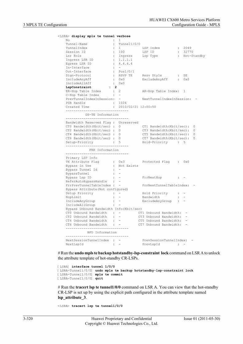
<LSRA> display mpls te tunnel verbose No : 1 Tunnel-Name : Tunnel1/0/0 TunnelIndex : 1 LSP Index : 2049 Session ID : 100 LSP ID : 32770 Lsr Role : Ingress Lsp Type : Hot-Standby Ingress LSR ID : 1.1.1.1 Egress LSR ID : 4.4.4.4 In-Interface : - Out-Interface : Pos1/0/1 Sign-Protocol : RSVP TE Resv Style : SE IncludeAnyAff : 0x0 ExcludeAnyAff : 0x0 IncludeAllAff : 0x0 LspConstraint : 2 ER-Hop Table Index : 2 AR-Hop Table Index: 1 C-Hop Table Index : - PrevTunnelIndexInSession: - NextTunnelIndexInSession: - PSB Handle : 1026 Created Time : 2010/02/21 12:00:50 -------------------------------- DS-TE Information -------------------------------- Bandwidth Reserved Flag : Unreserved CT0 Bandwidth(Kbit/sec) : 0 CT1 Bandwidth(Kbit/sec): 0 CT2 Bandwidth(Kbit/sec) : 0 CT3 Bandwidth(Kbit/sec): 0 CT4 Bandwidth(Kbit/sec) : 0 CT5 Bandwidth(Kbit/sec): 0 CT6 Bandwidth(Kbit/sec) : 0 CT7 Bandwidth(Kbit/sec): 0 Setup-Priority : 5 Hold-Priority : 5 -------------------------------- FRR Information -------------------------------- Primary LSP Info TE Attribute Flag : 0x3 Protected Flag : 0x0 Bypass In Use : Not Exists Bypass Tunnel Id : - BypassTunnel : - Bypass Lsp ID : - FrrNextHop : - ReferAutoBypassHandle : - FrrPrevTunnelTableIndex : - FrrNextTunnelTableIndex: - Bypass Attribute(Not configured) Setup Priority : - Hold Priority : - HopLimit : - Bandwidth : - IncludeAnyGroup : - ExcludeAnyGroup : - IncludeAllGroup : - Bypass Unbound Bandwidth Info(Kbit/sec) CT0 Unbound Bandwidth : - CT1 Unbound Bandwidth: - CT2 Unbound Bandwidth : - CT3 Unbound Bandwidth: - CT4 Unbound Bandwidth : - CT5 Unbound Bandwidth: - CT6 Unbound Bandwidth : - CT7 Unbound Bandwidth: - -------------------------------- BFD Information -------------------------------- NextSessionTunnelIndex : - PrevSessionTunnelIndex: - NextLspId : - PrevLspId : -
# Run the undo mpls te backup hotstandby-lsp-constraint lock command on LSR A to unlockthe attribute template of hot-standby CR-LSPs.
[LSRA] interface tunnel 1/0/0[LSRA-Tunnel1/0/0] undo mpls te backup hotstandby-lsp-constraint lock[LSRA-Tunnel1/0/0] mpls te commit[LSRA-Tunnel1/0/0] quit
# Run the tracert lsp te tunnel1/0/0 command on LSR A. You can view that the hot-standbyCR-LSP is set up by using the explicit path configured in the attribute template namedlsp_attribute_3.
<LSRA> tracert lsp te tunnel1/0/0
3 MPLS TE ConfigurationHUAWEI CX600 Metro Services Platform
Configuration Guide - MPLS
3-320 Huawei Proprietary and ConfidentialCopyright © Huawei Technologies Co., Ltd.
Issue 01 (2011-05-30)
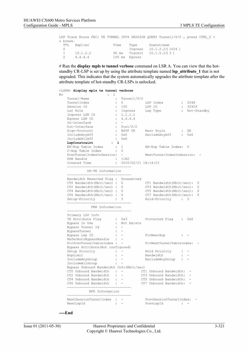
LSP Trace Route FEC: TE TUNNEL IPV4 SESSION QUERY Tunnel1/0/0 , press CTRL_C to break. TTL Replier Time Type Downstream 0 Ingress 10.1.2.2/[1024 ] 1 10.1.2.2 90 ms Transit 10.1.5.2/[3 ] 2 4.4.4.4 100 ms Egress
# Run the display mpls te tunnel verbose command on LSR A. You can view that the hot-standby CR-LSP is set up by using the attribute template named lsp_attribute_1 that is notupgraded. This indicates that the system automatically upgrades the attribute template after theattribute template of hot-standby CR-LSPs is unlocked.
<LSRA> display mpls te tunnel verboseNo : 1 Tunnel-Name : Tunnel1/0/0 TunnelIndex : 0 LSP Index : 2048 Session ID : 100 LSP ID : 32929 Lsr Role : Ingress Lsp Type : Hot-Standby Ingress LSR ID : 1.1.1.1 Egress LSR ID : 4.4.4.4 In-Interface : - Out-Interface : Pos1/0/2 Sign-Protocol : RSVP TE Resv Style : SE IncludeAnyAff : 0x0 ExcludeAnyAff : 0x0 IncludeAllAff : 0x0 LspConstraint : 1 ER-Hop Table Index : 1 AR-Hop Table Index: 0 C-Hop Table Index : 0 PrevTunnelIndexInSession: - NextTunnelIndexInSession: - PSB Handle : 1182 Created Time : 2010/02/21 18:14:23 -------------------------------- DS-TE Information -------------------------------- Bandwidth Reserved Flag : Unreserved CT0 Bandwidth(Kbit/sec) : 0 CT1 Bandwidth(Kbit/sec): 0 CT2 Bandwidth(Kbit/sec) : 0 CT3 Bandwidth(Kbit/sec): 0 CT4 Bandwidth(Kbit/sec) : 0 CT5 Bandwidth(Kbit/sec): 0 CT6 Bandwidth(Kbit/sec) : 0 CT7 Bandwidth(Kbit/sec): 0 Setup-Priority : 5 Hold-Priority : 5 -------------------------------- FRR Information -------------------------------- Primary LSP Info TE Attribute Flag : 0x3 Protected Flag : 0x0 Bypass In Use : Not Exists Bypass Tunnel Id : - BypassTunnel : - Bypass Lsp ID : - FrrNextHop : - ReferAutoBypassHandle : - FrrPrevTunnelTableIndex : - FrrNextTunnelTableIndex: - Bypass Attribute(Not configured) Setup Priority : - Hold Priority : - HopLimit : - Bandwidth : - IncludeAnyGroup : - ExcludeAnyGroup : - IncludeAllGroup : - Bypass Unbound Bandwidth Info(Kbit/sec) CT0 Unbound Bandwidth : - CT1 Unbound Bandwidth: - CT2 Unbound Bandwidth : - CT3 Unbound Bandwidth: - CT4 Unbound Bandwidth : - CT5 Unbound Bandwidth: - CT6 Unbound Bandwidth : - CT7 Unbound Bandwidth: - -------------------------------- BFD Information -------------------------------- NextSessionTunnelIndex : - PrevSessionTunnelIndex: - NextLspId : - PrevLspId : -
----End
HUAWEI CX600 Metro Services PlatformConfiguration Guide - MPLS 3 MPLS TE Configuration
Issue 01 (2011-05-30) Huawei Proprietary and ConfidentialCopyright © Huawei Technologies Co., Ltd.
3-321
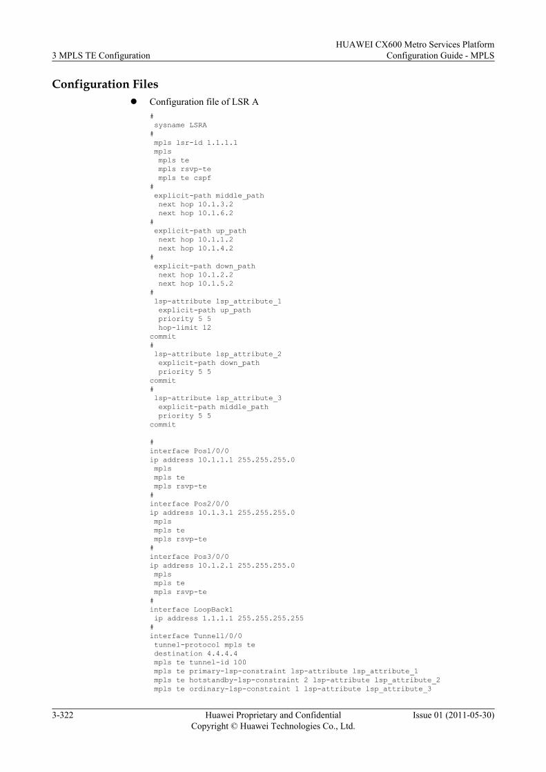
Configuration Filesl Configuration file of LSR A
# sysname LSRA# mpls lsr-id 1.1.1.1 mpls mpls te mpls rsvp-te mpls te cspf# explicit-path middle_path next hop 10.1.3.2 next hop 10.1.6.2# explicit-path up_path next hop 10.1.1.2 next hop 10.1.4.2# explicit-path down_path next hop 10.1.2.2 next hop 10.1.5.2# lsp-attribute lsp_attribute_1 explicit-path up_path priority 5 5 hop-limit 12commit# lsp-attribute lsp_attribute_2 explicit-path down_path priority 5 5commit# lsp-attribute lsp_attribute_3 explicit-path middle_path priority 5 5commit
#interface Pos1/0/0ip address 10.1.1.1 255.255.255.0 mpls mpls te mpls rsvp-te#interface Pos2/0/0ip address 10.1.3.1 255.255.255.0 mpls mpls te mpls rsvp-te#interface Pos3/0/0ip address 10.1.2.1 255.255.255.0 mpls mpls te mpls rsvp-te#interface LoopBack1 ip address 1.1.1.1 255.255.255.255#interface Tunnel1/0/0 tunnel-protocol mpls te destination 4.4.4.4 mpls te tunnel-id 100 mpls te primary-lsp-constraint lsp-attribute lsp_attribute_1 mpls te hotstandby-lsp-constraint 2 lsp-attribute lsp_attribute_2 mpls te ordinary-lsp-constraint 1 lsp-attribute lsp_attribute_3
3 MPLS TE ConfigurationHUAWEI CX600 Metro Services Platform
Configuration Guide - MPLS
3-322 Huawei Proprietary and ConfidentialCopyright © Huawei Technologies Co., Ltd.
Issue 01 (2011-05-30)
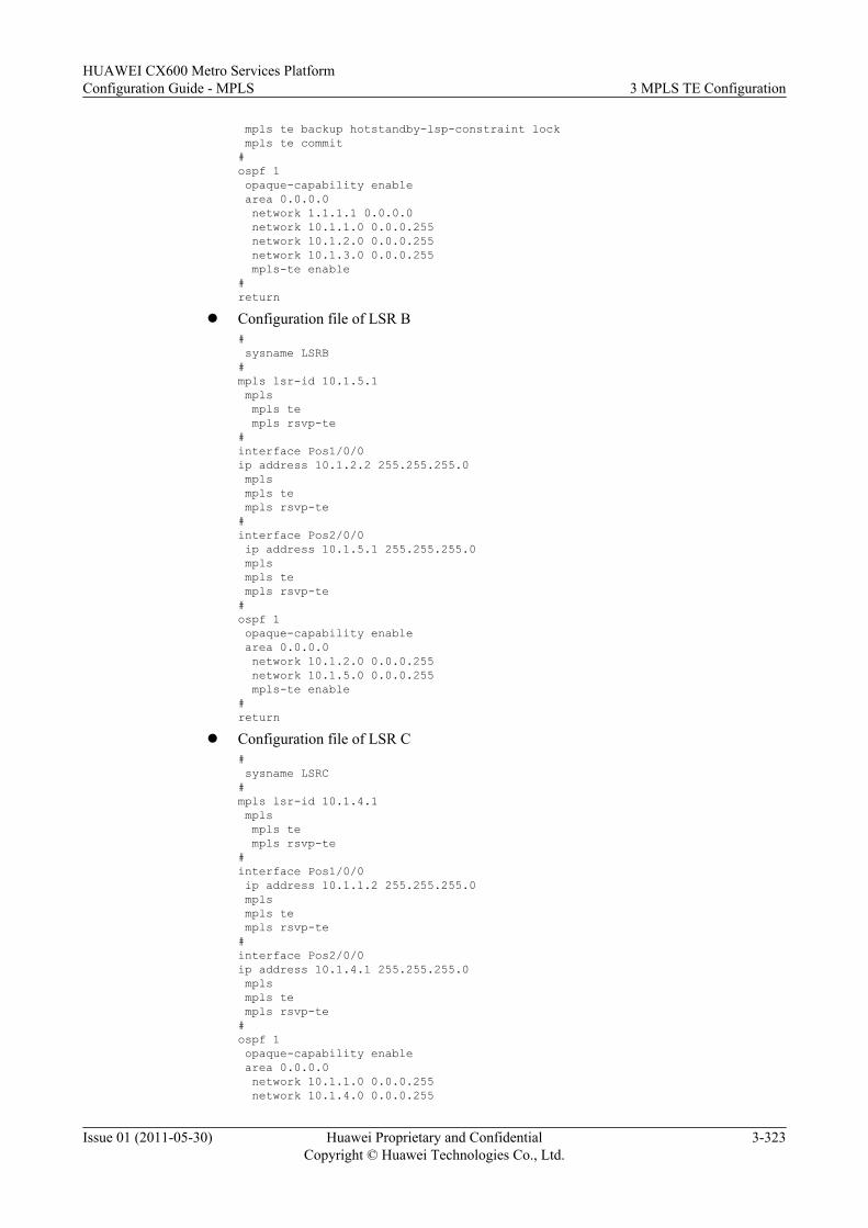
mpls te backup hotstandby-lsp-constraint lock mpls te commit#ospf 1 opaque-capability enable area 0.0.0.0 network 1.1.1.1 0.0.0.0 network 10.1.1.0 0.0.0.255 network 10.1.2.0 0.0.0.255 network 10.1.3.0 0.0.0.255 mpls-te enable#return
l Configuration file of LSR B# sysname LSRB#mpls lsr-id 10.1.5.1 mpls mpls te mpls rsvp-te#interface Pos1/0/0ip address 10.1.2.2 255.255.255.0 mpls mpls te mpls rsvp-te#interface Pos2/0/0 ip address 10.1.5.1 255.255.255.0 mpls mpls te mpls rsvp-te#ospf 1 opaque-capability enable area 0.0.0.0 network 10.1.2.0 0.0.0.255 network 10.1.5.0 0.0.0.255 mpls-te enable #return
l Configuration file of LSR C# sysname LSRC#mpls lsr-id 10.1.4.1 mpls mpls te mpls rsvp-te#interface Pos1/0/0 ip address 10.1.1.2 255.255.255.0 mpls mpls te mpls rsvp-te#interface Pos2/0/0ip address 10.1.4.1 255.255.255.0 mpls mpls te mpls rsvp-te#ospf 1 opaque-capability enable area 0.0.0.0 network 10.1.1.0 0.0.0.255 network 10.1.4.0 0.0.0.255
HUAWEI CX600 Metro Services PlatformConfiguration Guide - MPLS 3 MPLS TE Configuration
Issue 01 (2011-05-30) Huawei Proprietary and ConfidentialCopyright © Huawei Technologies Co., Ltd.
3-323
mpls-te enable #return
l Configuration file of LSR D# sysname LSRD# mpls lsr-id 4.4.4.4 mpls mpls te mpls rsvp-te#interface Pos1/0/0ip address 10.1.4.2 255.255.255.0 mpls mpls te mpls rsvp-te#interface Pos2/0/0ip address 10.1.6.2 255.255.255.0 mpls mpls te mpls rsvp-te#interface Pos3/0/0ip address 10.1.5.2 255.255.255.0 mpls mpls te mpls rsvp-te#interface LoopBack1 ip address 4.4.4.4 255.255.255.255#ospf 1 opaque-capability enable area 0.0.0.0 network 4.4.4.4 0.0.0.0 network 10.1.4.0 0.0.0.255 network 10.1.5.0 0.0.0.255 network 10.1.6.0 0.0.0.255 mpls-te enable #return
l Configuration file of LSR E# sysname LSRE# mpls lsr-id 10.1.6.1 mpls mpls te mpls rsvp-te#interface Pos1/0/0ip address 10.1.3.2 255.255.255.0 mpls mpls te mpls rsvp-te#interface Pos2/0/0ip address 10.1.6.1 255.255.255.0 mpls mpls te mpls rsvp-te#ospf 1 opaque-capability enable area 0.0.0.0 network 10.1.3.0 0.0.0.255
3 MPLS TE ConfigurationHUAWEI CX600 Metro Services Platform
Configuration Guide - MPLS
3-324 Huawei Proprietary and ConfidentialCopyright © Huawei Technologies Co., Ltd.
Issue 01 (2011-05-30)
network 10.1.6.0 0.0.0.255 mpls-te enable#return
3.26.21 Example for Configuring the Dynamic Bandwidth Functionfor a Hot-standby CR-LSP
This section describes how to configure the dynamic bandwidth function for a hot-standby CR-LSP. This function can save system resources.
Networking RequirementsFigure 3-22 is a networking diagram of CR-LSP hot standby. A TE tunnel is established fromPE1 to PE2. The tunnel is enabled with hot standby and configured with the best-effort path. Inthis manner, traffic is switched to the backup CR-LSP when the primary CR-LSP fails. If thebackup CR-LSP also fails, this triggers the establishment of a best-effort path, and then the trafficswitches to the best-effort path.
It is required that the dynamic bandwidth function for a hot-standby CR-LSP be configured onthe tunnel interface. This can achieve the following effects:
l When the primary CR-LSP works properly, the hot-standby CR-LSP does not occupybandwidth, saving bandwidth resources.
l If the primary tunnel fails, traffic switches to the hot-standby CR-LSP and then forwardedin a best-effort manner. The system then sets up a new CR-LSP with user-requestedbandwidth according to the make-before-break mechanism. After the new hot-standby CR-LSP is set up, the system switches traffic to this CR-LSP and deletes the hot-standby CR-LSP with bandwidth at 0 bit/s.
HUAWEI CX600 Metro Services PlatformConfiguration Guide - MPLS 3 MPLS TE Configuration
Issue 01 (2011-05-30) Huawei Proprietary and ConfidentialCopyright © Huawei Technologies Co., Ltd.
3-325
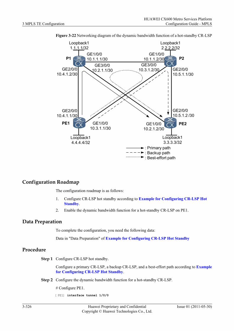
Figure 3-22 Networking diagram of the dynamic bandwidth function of a hot-standby CR-LSP
Loopback11.1.1.1/32
Loopback12.2.2.2/32
Loopback14.4.4.4/32
Loopback13.3.3.3/32
GE2/0/010.4.1.1/30
GE2/0/010.4.1.2/30
GE1/0/010.1.1.1/30
GE1/0/010.1.1.2/30
GE3/0/010.3.1.2/30 GE2/0/0
10.5.1.1/30
GE2/0/010.5.1.2 /30
GE1/0/010.2.1.2/30
GE3/0/010.2.1.1/30
GE1/0/010.3.1.1/30
: Primary path: Backup path: Best-effort path
PE1 PE2
P1 P2
Configuration RoadmapThe configuration roadmap is as follows:
1. Configure CR-LSP hot standby according to Example for Configuring CR-LSP HotStandby.
2. Enable the dynamic bandwidth function for a hot-standby CR-LSP on PE1.
Data PreparationTo complete the configuration, you need the following data:
Data in "Data Preparation" of Example for Configuring CR-LSP Hot Standby
Procedure
Step 1 Configure CR-LSP hot standby.
Configure a primary CR-LSP, a backup CR-LSP, and a best-effort path according to Examplefor Configuring CR-LSP Hot Standby.
Step 2 Configure the dynamic bandwidth function for a hot-standby CR-LSP.
# Configure PE1.
[PE1] interface tunnel 1/0/0
3 MPLS TE ConfigurationHUAWEI CX600 Metro Services Platform
Configuration Guide - MPLS
3-326 Huawei Proprietary and ConfidentialCopyright © Huawei Technologies Co., Ltd.
Issue 01 (2011-05-30)
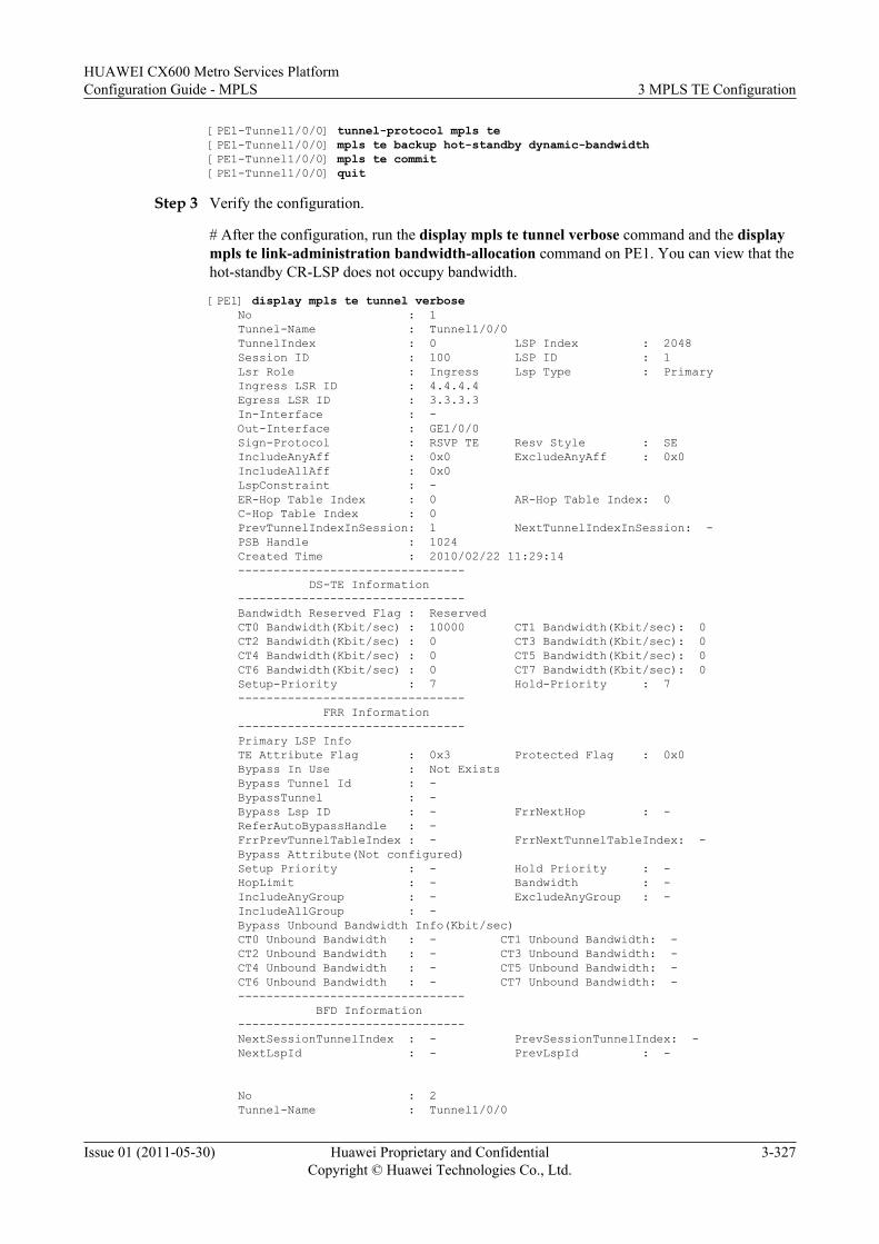
[PE1-Tunnel1/0/0] tunnel-protocol mpls te[PE1-Tunnel1/0/0] mpls te backup hot-standby dynamic-bandwidth[PE1-Tunnel1/0/0] mpls te commit[PE1-Tunnel1/0/0] quit
Step 3 Verify the configuration.
# After the configuration, run the display mpls te tunnel verbose command and the displaympls te link-administration bandwidth-allocation command on PE1. You can view that thehot-standby CR-LSP does not occupy bandwidth.
[PE1] display mpls te tunnel verbose No : 1 Tunnel-Name : Tunnel1/0/0 TunnelIndex : 0 LSP Index : 2048 Session ID : 100 LSP ID : 1 Lsr Role : Ingress Lsp Type : Primary Ingress LSR ID : 4.4.4.4 Egress LSR ID : 3.3.3.3 In-Interface : - Out-Interface : GE1/0/0 Sign-Protocol : RSVP TE Resv Style : SE IncludeAnyAff : 0x0 ExcludeAnyAff : 0x0 IncludeAllAff : 0x0 LspConstraint : - ER-Hop Table Index : 0 AR-Hop Table Index: 0 C-Hop Table Index : 0 PrevTunnelIndexInSession: 1 NextTunnelIndexInSession: - PSB Handle : 1024 Created Time : 2010/02/22 11:29:14 -------------------------------- DS-TE Information -------------------------------- Bandwidth Reserved Flag : Reserved CT0 Bandwidth(Kbit/sec) : 10000 CT1 Bandwidth(Kbit/sec): 0 CT2 Bandwidth(Kbit/sec) : 0 CT3 Bandwidth(Kbit/sec): 0 CT4 Bandwidth(Kbit/sec) : 0 CT5 Bandwidth(Kbit/sec): 0 CT6 Bandwidth(Kbit/sec) : 0 CT7 Bandwidth(Kbit/sec): 0 Setup-Priority : 7 Hold-Priority : 7 -------------------------------- FRR Information -------------------------------- Primary LSP Info TE Attribute Flag : 0x3 Protected Flag : 0x0 Bypass In Use : Not Exists Bypass Tunnel Id : - BypassTunnel : - Bypass Lsp ID : - FrrNextHop : - ReferAutoBypassHandle : - FrrPrevTunnelTableIndex : - FrrNextTunnelTableIndex: - Bypass Attribute(Not configured) Setup Priority : - Hold Priority : - HopLimit : - Bandwidth : - IncludeAnyGroup : - ExcludeAnyGroup : - IncludeAllGroup : - Bypass Unbound Bandwidth Info(Kbit/sec) CT0 Unbound Bandwidth : - CT1 Unbound Bandwidth: - CT2 Unbound Bandwidth : - CT3 Unbound Bandwidth: - CT4 Unbound Bandwidth : - CT5 Unbound Bandwidth: - CT6 Unbound Bandwidth : - CT7 Unbound Bandwidth: - -------------------------------- BFD Information -------------------------------- NextSessionTunnelIndex : - PrevSessionTunnelIndex: - NextLspId : - PrevLspId : -
No : 2 Tunnel-Name : Tunnel1/0/0
HUAWEI CX600 Metro Services PlatformConfiguration Guide - MPLS 3 MPLS TE Configuration
Issue 01 (2011-05-30) Huawei Proprietary and ConfidentialCopyright © Huawei Technologies Co., Ltd.
3-327
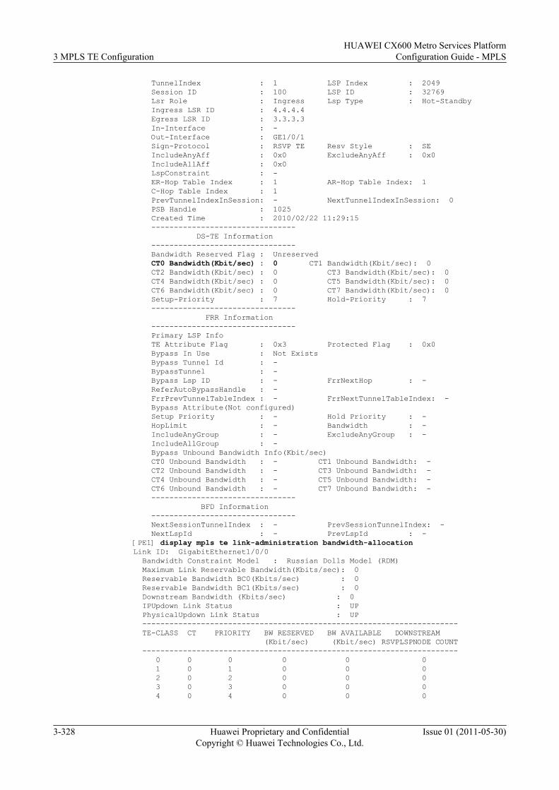
TunnelIndex : 1 LSP Index : 2049 Session ID : 100 LSP ID : 32769 Lsr Role : Ingress Lsp Type : Hot-Standby Ingress LSR ID : 4.4.4.4 Egress LSR ID : 3.3.3.3 In-Interface : - Out-Interface : GE1/0/1 Sign-Protocol : RSVP TE Resv Style : SE IncludeAnyAff : 0x0 ExcludeAnyAff : 0x0 IncludeAllAff : 0x0 LspConstraint : - ER-Hop Table Index : 1 AR-Hop Table Index: 1 C-Hop Table Index : 1 PrevTunnelIndexInSession: - NextTunnelIndexInSession: 0 PSB Handle : 1025 Created Time : 2010/02/22 11:29:15 -------------------------------- DS-TE Information -------------------------------- Bandwidth Reserved Flag : Unreserved CT0 Bandwidth(Kbit/sec) : 0 CT1 Bandwidth(Kbit/sec): 0 CT2 Bandwidth(Kbit/sec) : 0 CT3 Bandwidth(Kbit/sec): 0 CT4 Bandwidth(Kbit/sec) : 0 CT5 Bandwidth(Kbit/sec): 0 CT6 Bandwidth(Kbit/sec) : 0 CT7 Bandwidth(Kbit/sec): 0 Setup-Priority : 7 Hold-Priority : 7 -------------------------------- FRR Information -------------------------------- Primary LSP Info TE Attribute Flag : 0x3 Protected Flag : 0x0 Bypass In Use : Not Exists Bypass Tunnel Id : - BypassTunnel : - Bypass Lsp ID : - FrrNextHop : - ReferAutoBypassHandle : - FrrPrevTunnelTableIndex : - FrrNextTunnelTableIndex: - Bypass Attribute(Not configured) Setup Priority : - Hold Priority : - HopLimit : - Bandwidth : - IncludeAnyGroup : - ExcludeAnyGroup : - IncludeAllGroup : - Bypass Unbound Bandwidth Info(Kbit/sec) CT0 Unbound Bandwidth : - CT1 Unbound Bandwidth: - CT2 Unbound Bandwidth : - CT3 Unbound Bandwidth: - CT4 Unbound Bandwidth : - CT5 Unbound Bandwidth: - CT6 Unbound Bandwidth : - CT7 Unbound Bandwidth: - -------------------------------- BFD Information -------------------------------- NextSessionTunnelIndex : - PrevSessionTunnelIndex: - NextLspId : - PrevLspId : -[PE1] display mpls te link-administration bandwidth-allocationLink ID: GigabitEthernet1/0/0 Bandwidth Constraint Model : Russian Dolls Model (RDM) Maximum Link Reservable Bandwidth(Kbits/sec): 0 Reservable Bandwidth BC0(Kbits/sec) : 0 Reservable Bandwidth BC1(Kbits/sec) : 0 Downstream Bandwidth (Kbits/sec) : 0 IPUpdown Link Status : UP PhysicalUpdown Link Status : UP ---------------------------------------------------------------------- TE-CLASS CT PRIORITY BW RESERVED BW AVAILABLE DOWNSTREAM (Kbit/sec) (Kbit/sec) RSVPLSPNODE COUNT ---------------------------------------------------------------------- 0 0 0 0 0 0 1 0 1 0 0 0 2 0 2 0 0 0 3 0 3 0 0 0 4 0 4 0 0 0
3 MPLS TE ConfigurationHUAWEI CX600 Metro Services Platform
Configuration Guide - MPLS
3-328 Huawei Proprietary and ConfidentialCopyright © Huawei Technologies Co., Ltd.
Issue 01 (2011-05-30)
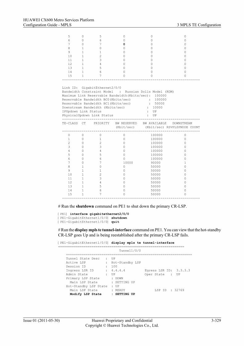
5 0 5 0 0 0 6 0 6 0 0 0 7 0 7 0 0 0 8 1 0 0 0 0 9 1 1 0 0 0 10 1 2 0 0 0 11 1 3 0 0 0 12 1 4 0 0 0 13 1 5 0 0 0 14 1 6 0 0 0 15 1 7 0 0 0 ----------------------------------------------------------------------
Link ID: GigabitEthernet2/0/0 Bandwidth Constraint Model : Russian Dolls Model (RDM) Maximum Link Reservable Bandwidth(Kbits/sec): 100000 Reservable Bandwidth BC0(Kbits/sec) : 100000 Reservable Bandwidth BC1(Kbits/sec) : 50000 Downstream Bandwidth (Kbits/sec) : 10000 IPUpdown Link Status : UP PhysicalUpdown Link Status : UP ---------------------------------------------------------------------- TE-CLASS CT PRIORITY BW RESERVED BW AVAILABLE DOWNSTREAM (Kbit/sec) (Kbit/sec) RSVPLSPNODE COUNT ---------------------------------------------------------------------- 0 0 0 0 100000 0 1 0 1 0 100000 0 2 0 2 0 100000 0 3 0 3 0 100000 0 4 0 4 0 100000 0 5 0 5 0 100000 0 6 0 6 0 100000 0 7 0 7 10000 90000 1 8 1 0 0 50000 0 9 1 1 0 50000 0 10 1 2 0 50000 0 11 1 3 0 50000 0 12 1 4 0 50000 0 13 1 5 0 50000 0 14 1 6 0 50000 0 15 1 7 0 50000 0 ----------------------------------------------------------------------
# Run the shutdown command on PE1 to shut down the primary CR-LSP.
[PE1] interface gigabitethernet2/0/0[PE1-GigabitEthernet1/0/0] shutdown[PE1-GigabitEthernet1/0/0] quit
# Run the display mpls te tunnel-interface command on PE1. You can view that the hot-standbyCR-LSP goes Up and is being reestablished after the primary CR-LSP fails.
[PE1-GigabitEthernet1/0/0] display mpls te tunnel-interface================================================================ Tunnel1/0/0 ================================================================ Tunnel State Desc : UP Active LSP : Hot-Standby LSP Session ID : 100 Ingress LSR ID : 4.4.4.4 Egress LSR ID: 3.3.3.3 Admin State : UP Oper State : UP Primary LSP State : DOWN Main LSP State : SETTING UP Hot-Standby LSP State : UP Main LSP State : READY LSP ID : 32769 Modify LSP State : SETTING UP
HUAWEI CX600 Metro Services PlatformConfiguration Guide - MPLS 3 MPLS TE Configuration
Issue 01 (2011-05-30) Huawei Proprietary and ConfidentialCopyright © Huawei Technologies Co., Ltd.
3-329
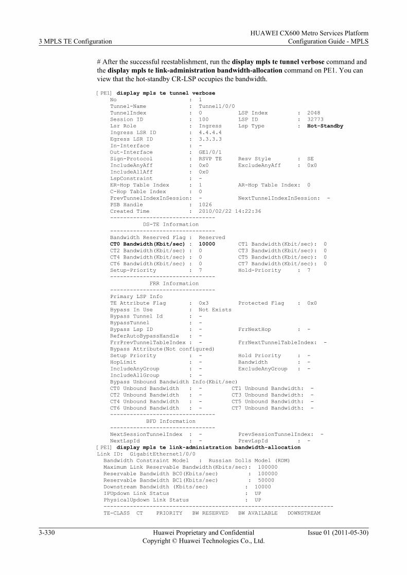
# After the successful reestablishment, run the display mpls te tunnel verbose command andthe display mpls te link-administration bandwidth-allocation command on PE1. You canview that the hot-standby CR-LSP occupies the bandwidth.
[PE1] display mpls te tunnel verbose No : 1 Tunnel-Name : Tunnel1/0/0 TunnelIndex : 0 LSP Index : 2048 Session ID : 100 LSP ID : 32773 Lsr Role : Ingress Lsp Type : Hot-Standby Ingress LSR ID : 4.4.4.4 Egress LSR ID : 3.3.3.3 In-Interface : - Out-Interface : GE1/0/1 Sign-Protocol : RSVP TE Resv Style : SE IncludeAnyAff : 0x0 ExcludeAnyAff : 0x0 IncludeAllAff : 0x0 LspConstraint : - ER-Hop Table Index : 1 AR-Hop Table Index: 0 C-Hop Table Index : 0 PrevTunnelIndexInSession: - NextTunnelIndexInSession: - PSB Handle : 1026 Created Time : 2010/02/22 14:22:36 -------------------------------- DS-TE Information -------------------------------- Bandwidth Reserved Flag : Reserved CT0 Bandwidth(Kbit/sec) : 10000 CT1 Bandwidth(Kbit/sec): 0 CT2 Bandwidth(Kbit/sec) : 0 CT3 Bandwidth(Kbit/sec): 0 CT4 Bandwidth(Kbit/sec) : 0 CT5 Bandwidth(Kbit/sec): 0 CT6 Bandwidth(Kbit/sec) : 0 CT7 Bandwidth(Kbit/sec): 0 Setup-Priority : 7 Hold-Priority : 7 -------------------------------- FRR Information -------------------------------- Primary LSP Info TE Attribute Flag : 0x3 Protected Flag : 0x0 Bypass In Use : Not Exists Bypass Tunnel Id : - BypassTunnel : - Bypass Lsp ID : - FrrNextHop : - ReferAutoBypassHandle : - FrrPrevTunnelTableIndex : - FrrNextTunnelTableIndex: - Bypass Attribute(Not configured) Setup Priority : - Hold Priority : - HopLimit : - Bandwidth : - IncludeAnyGroup : - ExcludeAnyGroup : - IncludeAllGroup : - Bypass Unbound Bandwidth Info(Kbit/sec) CT0 Unbound Bandwidth : - CT1 Unbound Bandwidth: - CT2 Unbound Bandwidth : - CT3 Unbound Bandwidth: - CT4 Unbound Bandwidth : - CT5 Unbound Bandwidth: - CT6 Unbound Bandwidth : - CT7 Unbound Bandwidth: - -------------------------------- BFD Information -------------------------------- NextSessionTunnelIndex : - PrevSessionTunnelIndex: - NextLspId : - PrevLspId : -[PE1] display mpls te link-administration bandwidth-allocationLink ID: GigabitEthernet1/0/0 Bandwidth Constraint Model : Russian Dolls Model (RDM) Maximum Link Reservable Bandwidth(Kbits/sec): 100000 Reservable Bandwidth BC0(Kbits/sec) : 100000 Reservable Bandwidth BC1(Kbits/sec) : 50000 Downstream Bandwidth (Kbits/sec) : 10000 IPUpdown Link Status : UP PhysicalUpdown Link Status : UP ---------------------------------------------------------------------- TE-CLASS CT PRIORITY BW RESERVED BW AVAILABLE DOWNSTREAM
3 MPLS TE ConfigurationHUAWEI CX600 Metro Services Platform
Configuration Guide - MPLS
3-330 Huawei Proprietary and ConfidentialCopyright © Huawei Technologies Co., Ltd.
Issue 01 (2011-05-30)
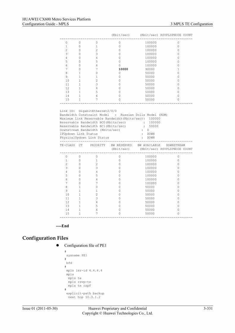
(Kbit/sec) (Kbit/sec) RSVPLSPNODE COUNT ---------------------------------------------------------------------- 0 0 0 0 100000 0 1 0 1 0 100000 0 2 0 2 0 100000 0 3 0 3 0 100000 0 4 0 4 0 100000 0 5 0 5 0 100000 0 6 0 6 0 100000 0 7 0 7 10000 90000 1 8 1 0 0 50000 0 9 1 1 0 50000 0 10 1 2 0 50000 0 11 1 3 0 50000 0 12 1 4 0 50000 0 13 1 5 0 50000 0 14 1 6 0 50000 0 15 1 7 0 50000 0 ----------------------------------------------------------------------
Link ID: GigabitEthernet2/0/0 Bandwidth Constraint Model : Russian Dolls Model (RDM) Maximum Link Reservable Bandwidth(Kbits/sec): 100000 Reservable Bandwidth BC0(Kbits/sec) : 100000 Reservable Bandwidth BC1(Kbits/sec) : 50000 Downstream Bandwidth (Kbits/sec) : 0 IPUpdown Link Status : DOWN PhysicalUpdown Link Status : DOWN ---------------------------------------------------------------------- TE-CLASS CT PRIORITY BW RESERVED BW AVAILABLE DOWNSTREAM (Kbit/sec) (Kbit/sec) RSVPLSPNODE COUNT ---------------------------------------------------------------------- 0 0 0 0 100000 0 1 0 1 0 100000 0 2 0 2 0 100000 0 3 0 3 0 100000 0 4 0 4 0 100000 0 5 0 5 0 100000 0 6 0 6 0 100000 0 7 0 7 0 100000 0 8 1 0 0 50000 0 9 1 1 0 50000 0 10 1 2 0 50000 0 11 1 3 0 50000 0 12 1 4 0 50000 0 13 1 5 0 50000 0 14 1 6 0 50000 0 15 1 7 0 50000 0 ----------------------------------------------------------------------
----End
Configuration Filesl Configuration file of PE1
# sysname PE1# bfd# mpls lsr-id 4.4.4.4 mpls mpls te mpls rsvp-te mpls te cspf# explicit-path backup next hop 10.3.1.2
HUAWEI CX600 Metro Services PlatformConfiguration Guide - MPLS 3 MPLS TE Configuration
Issue 01 (2011-05-30) Huawei Proprietary and ConfidentialCopyright © Huawei Technologies Co., Ltd.
3-331
next hop 10.5.1.2 next hop 3.3.3.3# explicit-path main next hop 10.4.1.2 next hop 10.2.1.2 next hop 3.3.3.3#isis 1 cost-style wide network-entity 10.0000.0000.0004.00 traffic-eng level-1-2#interface GigabitEthernet1/0/0 ip address 10.3.1.1 255.255.255.252 isis enable 1 mpls mpls te mpls te bandwidth max-reservable-bandwidth 100000 mpls te bandwidth bc0 50000 mpls rsvp-te#interface GigabitEthernet2/0/0 ip address 10.4.1.1 255.255.255.252 isis enable 1 mpls mpls te mpls te bandwidth max-reservable-bandwidth 100000 mpls te bandwidth bc0 100000 bc1 50000 mpls rsvp-te#interface LoopBack1 ip address 4.4.4.4 255.255.255.255 isis enable 1#interface Tunnel1/0/0 ip address unnumbered interface LoopBack1 tunnel-protocol mpls te destination 3.3.3.3 mpls te tunnel-id 100 mpls te record-route mpls te bandwidth ct0 10000 mpls te path explicit-path main mpls te path explicit-path backup secondary mpls te backup hot-standby wtr 15 mpls te backup ordinary best-effort tunnel-protocol mpls te mpls te backup hot-standby dynamic-bandwidth mpls te commit#return
l Configuration file of P1# sysname P1# mpls lsr-id 1.1.1.1 mpls mpls te mpls rsvp-te#isis 1 cost-style wide network-entity 10.0000.0000.0001.00 traffic-eng level-1-2#interface GigabitEthernet1/0/0 ip address 10.1.1.1 255.255.255.252 isis enable 1 mpls
3 MPLS TE ConfigurationHUAWEI CX600 Metro Services Platform
Configuration Guide - MPLS
3-332 Huawei Proprietary and ConfidentialCopyright © Huawei Technologies Co., Ltd.
Issue 01 (2011-05-30)
mpls te mpls rsvp-te#interface GigabitEthernet2/0/0 ip address 10.4.1.2 255.255.255.252 isis enable 1 mpls mpls te mpls rsvp-te#interface GigabitEthernet3/0/0 ip address 10.2.1.1 255.255.255.252 isis enable 1 mpls mpls te mpls te bandwidth max-reservable-bandwidth 100000 mpls te bandwidth bc0 100000 bc1 50000 mpls rsvp-te#interface LoopBack1 ip address 1.1.1.1 255.255.255.255 isis enable 1#return
l Configuration file of P2# sysname P2# mpls lsr-id 2.2.2.2 mpls mpls te mpls rsvp-te#isis 1 cost-style wide network-entity 10.0000.0000.0002.00 traffic-eng level-1-2#interface GigabitEthernet1/0/0 ip address 10.1.1.2 255.255.255.252 isis enable 1 mpls mpls te mpls te bandwidth max-reservable-bandwidth 100000 mpls te bandwidth bc0 100000 bc1 50000 mpls rsvp-te#interface GigabitEthernet2/0/0 ip address 10.5.1.1 255.255.255.252 isis enable 1 mpls mpls te mpls te bandwidth max-reservable-bandwidth 100000 mpls te bandwidth bc0 100000 bc1 50000 mpls rsvp-te#interface GigabitEthernet3/0/0 ip address 10.3.1.2 255.255.255.252 isis enable 1 mpls mpls te mpls rsvp-te#interface LoopBack1 ip address 2.2.2.2 255.255.255.255 isis enable 1#return
HUAWEI CX600 Metro Services PlatformConfiguration Guide - MPLS 3 MPLS TE Configuration
Issue 01 (2011-05-30) Huawei Proprietary and ConfidentialCopyright © Huawei Technologies Co., Ltd.
3-333
l Configuration file of PE2# sysname PE2# bfd# mpls lsr-id 3.3.3.3 mpls mpls te mpls rsvp-te#isis 1 cost-style wide network-entity 10.0000.0000.0003.00 traffic-eng level-1-2#interface GigabitEthernet1/0/0 ip address 10.2.1.2 255.255.255.252 isis enable 1 mpls mpls te mpls rsvp-te#interface GigabitEthernet2/0/0 ip address 10.5.1.2 255.255.255.252 isis enable 1 mpls mpls te mpls rsvp-te#interface LoopBack1 ip address 3.3.3.3 255.255.255.255 isis enable 1#return
3.26.22 Example for Configuring Synchronization of the BypassTunnel and the Backup CR-LSP
This section provides an example for configuring synchronization of the bypass CR-LSP andbackup CR-LSP. When the primary CR-LSP fails (in the FRR-in-use state), the system uses aTE FRR bypass tunnel and attempts to restore the primary CR-LSP and simultaneously establisha backup CR-LSP.
Networking RequirementsOn the network shown in Figure 3-23, a primary tunnel is set up by using the explicit path LSRA --> LSR B --> LSR C. A TE FRR bypass tunnel is set up on the transit LSR B along the pathLSR B --> LSR E --> LSR C; an ordinary CR-LSP is set up on the ingress LSR A along the pathLSR A --> LSR C.
After the link between LSR B and LSR C is faulty, the system starts the TE FRR bypass tunnel(the primary CR-LSP is in FRR-in-use state) and tries to restore the primary CR-LSP. At thesame time, the system tries to set up the backup CR-LSP.
3 MPLS TE ConfigurationHUAWEI CX600 Metro Services Platform
Configuration Guide - MPLS
3-334 Huawei Proprietary and ConfidentialCopyright © Huawei Technologies Co., Ltd.
Issue 01 (2011-05-30)
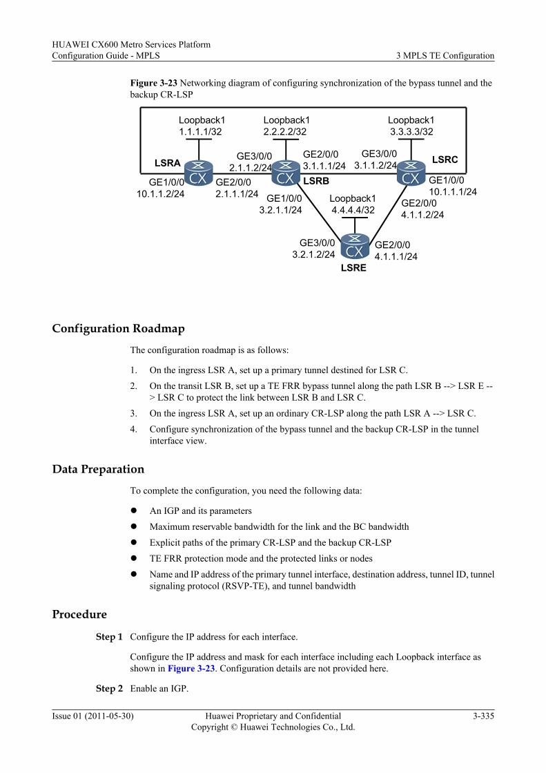
Figure 3-23 Networking diagram of configuring synchronization of the bypass tunnel and thebackup CR-LSP
Loopback14.4.4.4/32
Loopback12.2.2.2/32
GE2/0/02.1.1.1/24
GE3/0/02.1.1.2/24LSRA
GE2/0/03.1.1.1/24
GE3/0/03.1.1.2/24
LSRB
LSRC
LSRE
GE1/0/03.2.1.1/24
GE3/0/03.2.1.2/24
GE2/0/04.1.1.1/24
GE2/0/04.1.1.2/24
GE1/0/010.1.1.1/24
Loopback11.1.1.1/32
Loopback13.3.3.3/32
GE1/0/010.1.1.2/24
Configuration Roadmap
The configuration roadmap is as follows:
1. On the ingress LSR A, set up a primary tunnel destined for LSR C.2. On the transit LSR B, set up a TE FRR bypass tunnel along the path LSR B --> LSR E --
> LSR C to protect the link between LSR B and LSR C.3. On the ingress LSR A, set up an ordinary CR-LSP along the path LSR A --> LSR C.4. Configure synchronization of the bypass tunnel and the backup CR-LSP in the tunnel
interface view.
Data Preparation
To complete the configuration, you need the following data:
l An IGP and its parameters
l Maximum reservable bandwidth for the link and the BC bandwidth
l Explicit paths of the primary CR-LSP and the backup CR-LSP
l TE FRR protection mode and the protected links or nodes
l Name and IP address of the primary tunnel interface, destination address, tunnel ID, tunnelsignaling protocol (RSVP-TE), and tunnel bandwidth
Procedure
Step 1 Configure the IP address for each interface.
Configure the IP address and mask for each interface including each Loopback interface asshown in Figure 3-23. Configuration details are not provided here.
Step 2 Enable an IGP.
HUAWEI CX600 Metro Services PlatformConfiguration Guide - MPLS 3 MPLS TE Configuration
Issue 01 (2011-05-30) Huawei Proprietary and ConfidentialCopyright © Huawei Technologies Co., Ltd.
3-335
Enable OSPF or IS-IS on each LSR to ensure connectivity between devices. The example in thisdocument uses OSPF as IGP. For configuration details, see the configuration files in thisexample.
Step 3 Configure basic MPLS functions.
On each LSR, configure an LSR ID and enable MPLS in the system and interface views. Forconfiguration details, see the configuration files in this example.
Step 4 Configure basic MPLS TE functions.
On each LSR, enable MPLS-TE and MPLS RSVP-TE in the MPLS view and interface viewsof the link. Set the maximum reservable bandwidth of the link to 100 Mbit/s and the bandwidthof BC0 to 100 Mbit/s. For configuration details, see the configuration files in this example.
Step 5 Enable OSPF TE and configure the CSPF.
Enable OSPF TE on each LSR and configure the CSPF on LSR A and LSR B. For configurationdetails, see Configuring the RSVP-TE Tunnel.
Step 6 Configure the explicit paths of the primary and backup CR-LSPs.
# Configure the explicit path of the primary CR-LSP on LSR A.
[LSRA] explicit-path master[LSRA-explicit-path-master] next hop 2.1.1.2[LSRA-explicit-path-master] next hop 3.1.1.2
# Configure the explicit path of the backup CR-LSP on LSR A.
[LSRA] explicit-path backup[LSRA-explicit-path-backup] next hop 10.1.1.1
Step 7 Configure the tunnel interface.
# Create a tunnel interface on LSR A, specify an explicit path for the primary tunnel, and set thetunnel bandwidth to 20 Mbit/s.
[LSRA] interface tunnel2/0/0[LSRA-Tunnel2/0/0] ip address unnumbered interface loopback1[LSRA-Tunnel2/0/0] tunnel-protocol mpls te[LSRA-Tunnel2/0/0] destination 3.3.3.3[LSRA-Tunnel2/0/0] mpls te tunnel-id 200[LSRA-Tunnel2/0/0] mpls te record-route label[LSRA-Tunnel2/0/0] mpls te bandwidth ct0 20000[LSRA-Tunnel2/0/0] mpls te path explicit-path master[LSRA-Tunnel2/0/0] mpls te commit[LSRA-Tunnel2/0/0] quit
Step 8 Enable TE Auto FRR and configure link protection.
# Configure LSR A.
[LSRA] interface tunnel2/0/0[LSRA-Tunnel2/0/0] mpls te fast-reroute[LSRA-Tunnel2/0/0] mpls te commit[LSRA-Tunnel2/0/0] quit
# Configure LSR B.
[LSRB] interface gigabitethernet2/0/0[LSRB-GigabitEthernet2/0/0] mpls te auto-frr link[LSRB-GigabitEthernet2/0/0] quit
After the configurations, run the display mpls te tunnel path lsp-id 1.1.1.1 1 1 command onLSR A, and you can see that the bypass tunnel is set up successfully.
3 MPLS TE ConfigurationHUAWEI CX600 Metro Services Platform
Configuration Guide - MPLS
3-336 Huawei Proprietary and ConfidentialCopyright © Huawei Technologies Co., Ltd.
Issue 01 (2011-05-30)
[LSRA] display mpls te tunnel path lsp-id 1.1.1.1 1 1 Tunnel Interface Name : Tunnel2/0/0 Lsp ID : 1.1.1.1 :1 :1 Hop Information Hop 0 2.1.1.1 Hop 1 2.1.1.2 Label 11264 Hop 2 2.2.2.2 Label 11264 Hop 3 3.1.1.1 Local-Protection available Hop 4 3.1.1.2 Label 3 Hop 5 3.3.3.3 Label 3
Step 9 Configure an ordinary CR-LSP and specify its explicit path.
# Configure LSR A.
[LSRA] interface tunnel2/0/0[LSRA-Tunnel2/0/0] mpls te backup ordinary[LSRA-Tunnel2/0/0] mpls te path explicit-path backup secondary[LSRA-Tunnel2/0/0] mpls te commit[LSRA-Tunnel2/0/0] quit
Step 10 Configure synchronization of the bypass tunnel and the backup CR-LSP on the ingress LSR Aof the primary CR-LSP.
# Configure LSR A.
[LSRA] interface tunnel2/0/0[LSRA-Tunnel2/0/0] mpls te backup frr-in-use[LSRA-Tunnel2/0/0] mpls te commit[LSRA-Tunnel2/0/0] quit
Run the display mpls te tunnel-interface tunnel2/0/0 command on the ingress LSR A, and youcan view information about the primary CR-LSP.
[LSRA] display mpls te tunnel-interface tunnel2/0/0 ================================================================ Tunnel2/0/0 ================================================================ Tunnel State Desc : UP Active LSP : Primary LSP Session ID : 1 Ingress LSR ID : 1.1.1.1 Egress LSR ID: 3.3.3.3 Admin State : UP Oper State : UP Primary LSP State : UP Main LSP State : READY LSP ID : 2
Step 11 Verify the configuration.
# Disable the outbound interface that is protected on LSR B.
[LSRB] interface gigabitethernet 2/0/0[LSRB-GigabitEthernet2/0/0] shutdown
# Configure the affinity property of the tunnel on LSR A.
[LSRA] interface tunnel2/0/0[LSRA-Tunnel2/0/0] mpls te affinity property f0 mask ff secondary[LSRA-Tunnel2/0/0] mpls te commit[LSRA-Tunnel2/0/0] quit
Run the display mpls te tunnel-interface command on LSR A, and you can see that the tunnelstatus is Up. The primary tunnel is in FRR-in-use state; the ordinary CR-LSP is being set up;the primary CR-LSP is being restored.
================================================================ Tunnel2/0/0 ================================================================ Tunnel State Desc : UP
HUAWEI CX600 Metro Services PlatformConfiguration Guide - MPLS 3 MPLS TE Configuration
Issue 01 (2011-05-30) Huawei Proprietary and ConfidentialCopyright © Huawei Technologies Co., Ltd.
3-337
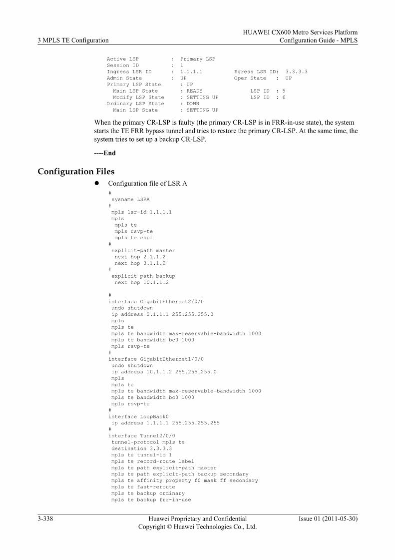
Active LSP : Primary LSP Session ID : 1 Ingress LSR ID : 1.1.1.1 Egress LSR ID: 3.3.3.3 Admin State : UP Oper State : UP Primary LSP State : UP Main LSP State : READY LSP ID : 5 Modify LSP State : SETTING UP LSP ID : 6 Ordinary LSP State : DOWN Main LSP State : SETTING UP
When the primary CR-LSP is faulty (the primary CR-LSP is in FRR-in-use state), the systemstarts the TE FRR bypass tunnel and tries to restore the primary CR-LSP. At the same time, thesystem tries to set up a backup CR-LSP.
----End
Configuration Filesl Configuration file of LSR A
# sysname LSRA# mpls lsr-id 1.1.1.1 mpls mpls te mpls rsvp-te mpls te cspf# explicit-path master next hop 2.1.1.2 next hop 3.1.1.2# explicit-path backup next hop 10.1.1.2
#interface GigabitEthernet2/0/0 undo shutdown ip address 2.1.1.1 255.255.255.0 mpls mpls te mpls te bandwidth max-reservable-bandwidth 1000 mpls te bandwidth bc0 1000 mpls rsvp-te#interface GigabitEthernet1/0/0 undo shutdown ip address 10.1.1.2 255.255.255.0 mpls mpls te mpls te bandwidth max-reservable-bandwidth 1000 mpls te bandwidth bc0 1000 mpls rsvp-te#interface LoopBack0 ip address 1.1.1.1 255.255.255.255#interface Tunnel2/0/0 tunnel-protocol mpls te destination 3.3.3.3 mpls te tunnel-id 1 mpls te record-route label mpls te path explicit-path master mpls te path explicit-path backup secondary mpls te affinity property f0 mask ff secondary mpls te fast-reroute mpls te backup ordinary mpls te backup frr-in-use
3 MPLS TE ConfigurationHUAWEI CX600 Metro Services Platform
Configuration Guide - MPLS
3-338 Huawei Proprietary and ConfidentialCopyright © Huawei Technologies Co., Ltd.
Issue 01 (2011-05-30)
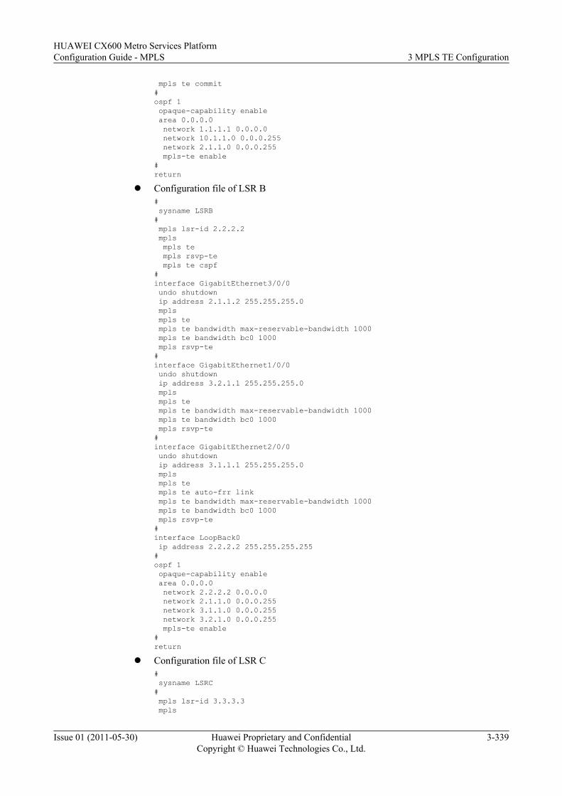
mpls te commit#ospf 1 opaque-capability enable area 0.0.0.0 network 1.1.1.1 0.0.0.0 network 10.1.1.0 0.0.0.255 network 2.1.1.0 0.0.0.255 mpls-te enable#return
l Configuration file of LSR B# sysname LSRB# mpls lsr-id 2.2.2.2 mpls mpls te mpls rsvp-te mpls te cspf#interface GigabitEthernet3/0/0 undo shutdown ip address 2.1.1.2 255.255.255.0 mpls mpls te mpls te bandwidth max-reservable-bandwidth 1000 mpls te bandwidth bc0 1000 mpls rsvp-te#interface GigabitEthernet1/0/0 undo shutdown ip address 3.2.1.1 255.255.255.0 mpls mpls te mpls te bandwidth max-reservable-bandwidth 1000 mpls te bandwidth bc0 1000 mpls rsvp-te#interface GigabitEthernet2/0/0 undo shutdown ip address 3.1.1.1 255.255.255.0 mpls mpls te mpls te auto-frr link mpls te bandwidth max-reservable-bandwidth 1000 mpls te bandwidth bc0 1000 mpls rsvp-te#interface LoopBack0 ip address 2.2.2.2 255.255.255.255#ospf 1 opaque-capability enable area 0.0.0.0 network 2.2.2.2 0.0.0.0 network 2.1.1.0 0.0.0.255 network 3.1.1.0 0.0.0.255 network 3.2.1.0 0.0.0.255 mpls-te enable#return
l Configuration file of LSR C# sysname LSRC# mpls lsr-id 3.3.3.3 mpls
HUAWEI CX600 Metro Services PlatformConfiguration Guide - MPLS 3 MPLS TE Configuration
Issue 01 (2011-05-30) Huawei Proprietary and ConfidentialCopyright © Huawei Technologies Co., Ltd.
3-339
mpls te mpls rsvp-te mpls te cspf#interface GigabitEthernet2/0/0 undo shutdown ip address 4.1.1.2 255.255.255.0 mpls mpls te mpls te bandwidth max-reservable-bandwidth 1000 mpls te bandwidth bc0 1000 mpls rsvp-te#interface GigabitEthernet1/0/0 undo shutdown ip address 10.1.1.1 255.255.255.0 mpls mpls te mpls te bandwidth max-reservable-bandwidth 1000 mpls te bandwidth bc0 1000 mpls rsvp-te#interface GigabitEthernet3/0/0 undo shutdown ip address 3.1.1.2 255.255.255.0 mpls mpls te mpls te bandwidth max-reservable-bandwidth 1000 mpls te bandwidth bc0 1000 mpls rsvp-te#interface LoopBack0 ip address 3.3.3.3 255.255.255.255#ospf 1 opaque-capability enable area 0.0.0.0 network 3.3.3.3 0.0.0.0 network 3.1.1.0 0.0.0.255 network 4.1.1.0 0.0.0.255 network 10.1.1.0 0.0.0.255 mpls-te enable#return
l Configuration file of LSR E# sysname LSRE# mpls lsr-id 4.4.4.4 mpls mpls te mpls rsvp-te mpls te cspf#interface GigabitEthernet2/0/0 undo shutdown ip address 4.1.1.1 255.255.255.0 mpls mpls te mpls te bandwidth max-reservable-bandwidth 1000 mpls te bandwidth bc0 1000 mpls rsvp-te#interface GigabitEthernet3/0/0 undo shutdown ip address 3.2.1.2 255.255.255.0 mpls mpls te mpls te bandwidth max-reservable-bandwidth 1000
3 MPLS TE ConfigurationHUAWEI CX600 Metro Services Platform
Configuration Guide - MPLS
3-340 Huawei Proprietary and ConfidentialCopyright © Huawei Technologies Co., Ltd.
Issue 01 (2011-05-30)
mpls te bandwidth bc0 1000 mpls rsvp-te#interface LoopBack0 ip address 4.4.4.4 255.255.255.255#ospf 1 opaque-capability enable area 0.0.0.0 network 4.4.4.4 0.0.0.0 network 3.2.1.0 0.0.0.255 network 4.1.1.0 0.0.0.255 mpls-te enable#return
3.26.23 Example for Configuring RSVP GRThis section provides an example for configuring RSVP GR to ensure uninterrupted MPLSforwarding during the AMB/SMB switchover.
Networking RequirementsOn the network shown in Figure 3-24, LSR A, LSR B, and LSR C are equipped with dual maincontrol boards. Three LSRs learn routes from each other through the IS-IS protocol, and thenuse the RSVP protocol to set up a TE tunnel from LSR A to LSR C.
RSVP GR is required to ensure that MPLS forwarding is not interrupted when the master/slaveswitchover of main control boards occurs on LSR A, LSR B, or LSR C.
Figure 3-24 Example for Configuring RSVP-TE GR
LSRB
GE1/0/010.1.1.1/24
GE1/0/010.1.1.2/24
LSRA LSRC
GE2/0/020.1.1.1/24
GE2/0/020.1.1.2/24
Loopback11.1.1.1/32
Loopback12.2.2.2/32
Loopback13.3.3.3/32
Configuration RoadmapThe configuration roadmap is as follows:
1. Configure IP addresses for interfaces on each LSR and loopback addresses that functionas the LSR IDs.
2. Configure the IS-IS protocol and enable IS-IS TE.3. Configure LSR IDs.4. Enable MPLS, MPLS TE, and MPLS RSVP-TE globally.5. Enable MPLS, MPLS TE, and MPLS RSVP-TE on each interface, and configure bandwidth
attributes of the MPLS TE link.6. Enable MPLS CSPF on the ingress node. Create the tunnel interface at the ingress node.
Specify the tunnel IP address, tunnel protocol, destination address, tunnel ID, and signalingprotocol.
HUAWEI CX600 Metro Services PlatformConfiguration Guide - MPLS 3 MPLS TE Configuration
Issue 01 (2011-05-30) Huawei Proprietary and ConfidentialCopyright © Huawei Technologies Co., Ltd.
3-341
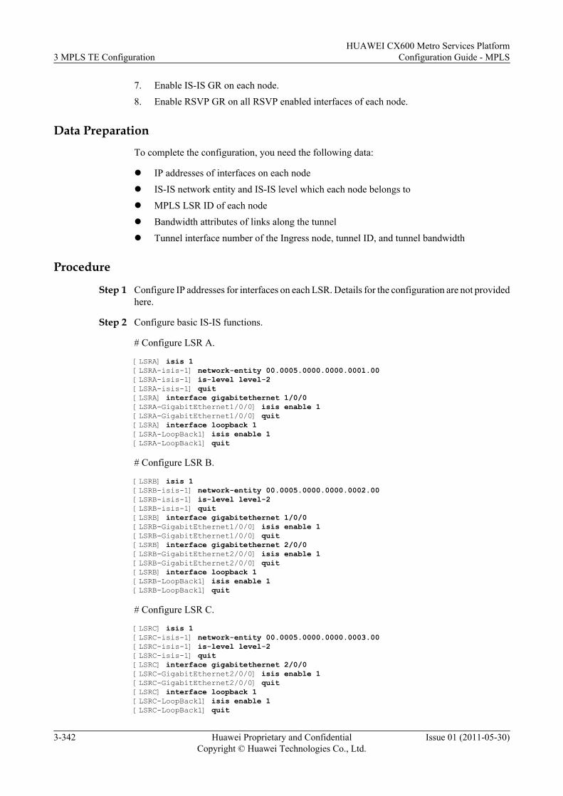
7. Enable IS-IS GR on each node.8. Enable RSVP GR on all RSVP enabled interfaces of each node.
Data Preparation
To complete the configuration, you need the following data:
l IP addresses of interfaces on each nodel IS-IS network entity and IS-IS level which each node belongs tol MPLS LSR ID of each nodel Bandwidth attributes of links along the tunnell Tunnel interface number of the Ingress node, tunnel ID, and tunnel bandwidth
Procedure
Step 1 Configure IP addresses for interfaces on each LSR. Details for the configuration are not providedhere.
Step 2 Configure basic IS-IS functions.
# Configure LSR A.
[LSRA] isis 1[LSRA-isis-1] network-entity 00.0005.0000.0000.0001.00[LSRA-isis-1] is-level level-2[LSRA-isis-1] quit[LSRA] interface gigabitethernet 1/0/0[LSRA-GigabitEthernet1/0/0] isis enable 1[LSRA-GigabitEthernet1/0/0] quit[LSRA] interface loopback 1[LSRA-LoopBack1] isis enable 1[LSRA-LoopBack1] quit
# Configure LSR B.
[LSRB] isis 1[LSRB-isis-1] network-entity 00.0005.0000.0000.0002.00[LSRB-isis-1] is-level level-2[LSRB-isis-1] quit[LSRB] interface gigabitethernet 1/0/0[LSRB-GigabitEthernet1/0/0] isis enable 1[LSRB-GigabitEthernet1/0/0] quit[LSRB] interface gigabitethernet 2/0/0[LSRB-GigabitEthernet2/0/0] isis enable 1[LSRB-GigabitEthernet2/0/0] quit[LSRB] interface loopback 1[LSRB-LoopBack1] isis enable 1[LSRB-LoopBack1] quit
# Configure LSR C.
[LSRC] isis 1[LSRC-isis-1] network-entity 00.0005.0000.0000.0003.00[LSRC-isis-1] is-level level-2[LSRC-isis-1] quit[LSRC] interface gigabitethernet 2/0/0[LSRC-GigabitEthernet2/0/0] isis enable 1[LSRC-GigabitEthernet2/0/0] quit[LSRC] interface loopback 1[LSRC-LoopBack1] isis enable 1[LSRC-LoopBack1] quit
3 MPLS TE ConfigurationHUAWEI CX600 Metro Services Platform
Configuration Guide - MPLS
3-342 Huawei Proprietary and ConfidentialCopyright © Huawei Technologies Co., Ltd.
Issue 01 (2011-05-30)
After the configuration, run the display ip routing-table command on each LSR, and you cansee that LSRs have learned routes from each other.
Step 3 Configure basic MPLS capability and enable MPLS TE, RSVP-TE, and CSPF. Configuremaximum bandwidth and maximum reservable bandwidth of interfaces.
# Configure LSR A.
[LSRA] mpls lsr-id 1.1.1.1[LSRA] mpls[LSRA-mpls] mpls te[LSRA-mpls] mpls rsvp-te[LSRA-mpls] mpls te cspf[LSRA-mpls] quit[LSRA] interface gigabitethernet 1/0/0[LSRA-GigabitEthernet1/0/0] mpls[LSRA-GigabitEthernet1/0/0] mpls te[LSRA-GigabitEthernet1/0/0] mpls rsvp-te[LSRA-GigabitEthernet1/0/0] mpls te bandwidth max-reservable-bandwidth 100000[LSRA-GigabitEthernet1/0/0] mpls te bandwidth bc0 100000[LSRA-GigabitEthernet1/0/0] quit
# Configure LSR B.
[LSRB] mpls lsr-id 2.2.2.2[LSRB] mpls[LSRB-mpls] mpls te[LSRB-mpls] mpls rsvp-te[LSRB-mpls] quit[LSRB] interface gigabitethernet 1/0/0[LSRB-GigabitEthernet1/0/0] mpls[LSRB-GigabitEthernet1/0/0] mpls te[LSRB-GigabitEthernet1/0/0] mpls rsvp-te[LSRB-GigabitEthernet1/0/0] quit[LSRB] interface gigabitethernet 2/0/0[LSRB-GigabitEthernet2/0/0] mpls[LSRB-GigabitEthernet2/0/0] mpls te[LSRB-GigabitEthernet2/0/0] mpls rsvp-te[LSRB-GigabitEthernet2/0/0] mpls te bandwidth max-reservable-bandwidth 100000[LSRB-GigabitEthernet2/0/0] mpls te bandwidth bc0 100000[LSRB-GigabitEthernet2/0/0] quit
# Configure LSR C.
[LSRC] mpls lsr-id 3.3.3.3[LSRC] mpls[LSRC-mpls] mpls te[LSRC-mpls] mpls rsvp-te[LSRC-mpls] quit[LSRC] interface gigabitethernet 2/0/0[LSRC-GigabitEthernet2/0/0] mpls[LSRC-GigabitEthernet2/0/0] mpls te[LSRC-GigabitEthernet2/0/0] mpls rsvp-te[LSRC-GigabitEthernet2/0/0] quit
Step 4 Configure IS-IS TE and enable IS-IS GR.
# Configure LSR A.
[LSRA] isis 1[LSRA-isis-1] cost-style wide[LSRA-isis-1] is-name LSRA[LSRA-isis-1] traffic-eng level-2[LSRA-isis-1] graceful-restart[LSRA-isis-1] quit
# Configure LSR B.
[LSRB] isis 1
HUAWEI CX600 Metro Services PlatformConfiguration Guide - MPLS 3 MPLS TE Configuration
Issue 01 (2011-05-30) Huawei Proprietary and ConfidentialCopyright © Huawei Technologies Co., Ltd.
3-343
[LSRB-isis-1] cost-style wide[LSRB-isis-1] is-name LSRB[LSRB-isis-1] traffic-eng level-2[LSRB-isis-1] graceful-restart[LSRB-isis-1] quit
# Configure LSR C.
[LSRC] isis 1[LSRC-isis-1] cost-style wide[LSRC-isis-1] is-name LSRC[LSRC-isis-1] traffic-eng level-2[LSRC-isis-1] graceful-restart[LSRC-isis-1] quit
Step 5 Configure an MPLS TE tunnel.
# Configure an MPLS TE tunnel on LSR A.
[LSRA] interface tunnel 1/0/0[LSRA-Tunnel1/0/0] ip address unnumbered interface loopback 1[LSRA-Tunnel1/0/0] tunnel-protocol mpls te[LSRA-Tunnel1/0/0] destination 3.3.3.3[LSRA-Tunnel1/0/0] mpls te tunnel-id 100[LSRA-Tunnel1/0/0] mpls te signal-protocol rsvp-te[LSRA-Tunnel1/0/0] mpls te bandwidth ct0 20000[LSRA-Tunnel1/0/0] mpls te commit[LSRA-Tunnel1/0/0] quit
After the configuration, run the display interface tunnel command on LSR A, and you can seethat the interface status of the MPLS TE tunnel is Up.
[LSRA] display interface tunnelTunnel1/0/0 current state : UPLine protocol current state : UPLast up time: 2007-10-29, 16:35:10Description : Tunnel1/0/0 Interface...
Step 6 Enable RSVP GR.
# Configure LSR A.
[LSRA] mpls[LSRA-mpls] mpls rsvp-te hello[LSRA-mpls] mpls rsvp-te hello full-gr[LSRA-mpls] quit[LSRA] interface gigabitethernet 1/0/0[LSRA-GigabitEthernet1/0/0] mpls rsvp-te hello
# Configure LSR B.
[LSRB] mpls[LSRB-mpls] mpls rsvp-te hello[LSRB-mpls] mpls rsvp-te hello full-gr[LSRB-mpls] quit[LSRB] interface gigabitethernet 1/0/0[LSRB-GigabitEthernet1/0/0] mpls rsvp-te hello[LSRB] interface gigabitethernet 2/0/0[LSRB-GigabitEthernet2/0/0] mpls rsvp-te hello
# Configure LSR C.
[LSRC] mpls[LSRC-mpls] mpls rsvp-te hello[LSRC-mpls] mpls rsvp-te hello full-gr[LSRC-mpls] quit[LSRC] interface gigabitethernet 2/0/0[LSRC-GigabitEthernet2/0/0] mpls rsvp-te hello
3 MPLS TE ConfigurationHUAWEI CX600 Metro Services Platform
Configuration Guide - MPLS
3-344 Huawei Proprietary and ConfidentialCopyright © Huawei Technologies Co., Ltd.
Issue 01 (2011-05-30)
Step 7 Verify the configuration.
After the configuration, run the display mpls rsvp-te graceful-restart command on LSR B,and you can view the local GR status, restart time, and recovery time.
[LSRB] display mpls rsvp-te graceful-restartDisplay Mpls Rsvp te graceful restart information LSR ID: 2.2.2.2 Graceful-Restart Capability: GR-Self GR-Support Restart Time: 90060 Milli Second Recovery Time: 0 Milli Second GR Status: Gracefully Restart Not going on Number of Restarting neighbors: 0 Number of LSPs recovered: 0 Received Gr Path message count: 0 Send Gr Path message count: 0 Received RecoveryPath message count: 0 Send RecoveryPath message count: 0
Run the display mpls rsvp-te graceful-restart peer command on LSR B, and you can viewthe GR status of the neighboring LSR.
[LSRB] display mpls rsvp-te graceful-restart peerNeighbor on Interface GigabitEthernet1/0/0 Neighbor Addr: 10.1.1.1 SrcInstance: 47860 NbrSrcInstance: 49409 Neighbor Capability: Can Do Self GR Can Support GR GR Status: Normal Restart Time: 90060 Milli Second Recovery Time: 0 Milli Second Stored GR message number: 0
If the master/slave switchover is performed, you can see that during the graceful-restart Tunnel1/0/0 keeps up.
Run the display this interface command on LSR A, and you can view that the value of Tunnelup/down statistics is 0, indicating that the tunnel has never flapped.
[LSRA] display this interfaceTunnel1/0/0 current state : UPLine protocol current state : UPLast line protocol up time : 2010-07-13 16:10:09Description: Tunnel1/0/0 InterfaceRoute Port,The Maximum Transmit Unit is 1500Internet protocol processing : disabledEncapsulation is TUNNEL, loopback not setTunnel destination 3.3.3.3Tunnel up/down statistics 0Tunnel protocol/transport MPLS/MPLS, ILM is available,...
# Run the slave switchover command on LSR B to forcibly perform the master/slave switchoverof main control boards.
[LSRB] slave switchover enable[LSRB] slave switchoverCaution!!! Confirm switch slave to master[Y/N] ?[LSRB] y
Run the display this interface command on LSR A again, and you can view that the value ofTunnel up/down statistics is still 0, indicating that the tunnel did not flap after the master/slaveswitchover of main control boards on LSR B. This means that RSVP GR has been configuredsuccessfully.
[LSRA] display this interface
HUAWEI CX600 Metro Services PlatformConfiguration Guide - MPLS 3 MPLS TE Configuration
Issue 01 (2011-05-30) Huawei Proprietary and ConfidentialCopyright © Huawei Technologies Co., Ltd.
3-345
Tunnel1/0/0 current state : UPLine protocol current state : UPLast line protocol up time : 2010-07-13 16:13:53Description: Tunnel1/0/0 InterfaceRoute Port,The Maximum Transmit Unit is 1500Internet protocol processing : disabledEncapsulation is TUNNEL, loopback not setTunnel destination 3.3.3.3Tunnel up/down statistics 0Tunnel protocol/transport MPLS/MPLS, ILM is available,...
----End
Configuration Filesl Configuration file of LSR A
# sysname LSRA# mpls lsr-id 1.1.1.1 mpls mpls te mpls rsvp-te mpls te cspf mpls rsvp-te hello mpls rsvp-te hello full-gr#isis 1 graceful-restart is-level level-2 cost-style wide is-name LSRA network-entity 00.0005.0000.0000.0001.00 traffic-eng level-2#interface GigabitEthernet1/0/0 ip address 10.1.1.1 255.255.255.0 isis enable 1 mpls mpls te mpls te bandwidth max-reservable-bandwidth 100000 mpls te bandwidth bc0 100000 mpls rsvp-te mpls rsvp-te hello#interface LoopBack1 ip address 1.1.1.1 255.255.255.255 isis enable 1#interface Tunnel1/0/0 ip address unnumbered interface LoopBack1 tunnel-protocol mpls te destination 3.3.3.3 mpls te tunnel-id 100 mpls te bandwidth ct0 20000 mpls te commit#return
l Configuration file of LSR B# sysname LSRB#slave switchover enableslave switchover# mpls lsr-id 2.2.2.2
3 MPLS TE ConfigurationHUAWEI CX600 Metro Services Platform
Configuration Guide - MPLS
3-346 Huawei Proprietary and ConfidentialCopyright © Huawei Technologies Co., Ltd.
Issue 01 (2011-05-30)
mpls mpls te mpls rsvp-te mpls rsvp-te hello mpls rsvp-te hello full-gr#isis 1 graceful-restart is-level level-2 cost-style wide is-name LSRB network-entity 00.0005.0000.0000.0002.00 traffic-eng level-2#interface GigabitEthernet1/0/0 ip address 10.1.1.2 255.255.255.0 isis enable 1 mpls mpls te mpls rsvp-te mpls rsvp-te hello#interface GigabitEthernet2/0/0ip address 20.1.1.1 255.255.255.0 isis enable 1 mpls mpls te mpls te bandwidth max-reservable-bandwidth 100000 mpls te bandwidth bc0 100000 mpls rsvp-te mpls rsvp-te hello#interface LoopBack1 ip address 2.2.2.2 255.255.255.255 isis enable 1#return
l Configuration file of LSR C# sysname LSRC# mpls lsr-id 3.3.3.3 mpls mpls te mpls rsvp-te mpls rsvp-te hello mpls rsvp-te hello full-gr#isis 1 graceful-restart is-level level-2 cost-style wide is-name LSRC network-entity 00.0005.0000.0000.0003.00 traffic-eng level-2#interface GigabitEthernet1/0/0 ip address 20.1.1.2 255.255.255.0 isis enable 1 mpls mpls te mpls rsvp-te mpls rsvp-te hello#interface LoopBack1 ip address 3.3.3.3 255.255.255.255 isis enable 1#
HUAWEI CX600 Metro Services PlatformConfiguration Guide - MPLS 3 MPLS TE Configuration
Issue 01 (2011-05-30) Huawei Proprietary and ConfidentialCopyright © Huawei Technologies Co., Ltd.
3-347
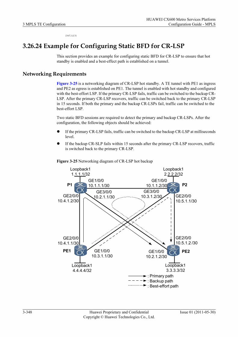
return
3.26.24 Example for Configuring Static BFD for CR-LSPThis section provides an example for configuring static BFD for CR-LSP to ensure that hotstandby is enabled and a best-effect path is established on a tunnel.
Networking Requirements
Figure 3-25 is a networking diagram of CR-LSP hot standby. A TE tunnel with PE1 as ingressand PE2 as egress is established on PE1. The tunnel is enabled with hot standby and configuredwith the best-effort LSP. If the primary CR-LSP fails, traffic can be switched to the backup CR-LSP. After the primary CR-LSP recovers, traffic can be switched back to the primary CR-LSPin 15 seconds. If both the primary and the backup CR-LSPs fail, traffic can be switched to thebest-effort LSP.
Two static BFD sessions are required to detect the primary and backup CR-LSPs. After theconfiguration, the following objects should be achieved:
l If the primary CR-LSP fails, traffic can be switched to the backup CR-LSP at millisecondslevel.
l If the backup CR-SLP fails within 15 seconds after the primary CR-LSP recovers, trafficis switched back to the primary CR-LSP.
Figure 3-25 Networking diagram of CR-LSP hot backup
Loopback11.1.1.1/32
Loopback12.2.2.2/32
Loopback14.4.4.4/32
Loopback13.3.3.3/32
GE2/0/010.4.1.1/30
GE2/0/010.4.1.2/30
GE1/0/010.1.1.1/30
GE1/0/010.1.1.2/30
GE3/0/010.3.1.2/30 GE2/0/0
10.5.1.1/30
GE2/0/010.5.1.2 /30
GE1/0/010.2.1.2/30
GE3/0/010.2.1.1/30
GE1/0/010.3.1.1/30
: Primary path: Backup path: Best-effort path
PE1 PE2
P1 P2
3 MPLS TE ConfigurationHUAWEI CX600 Metro Services Platform
Configuration Guide - MPLS
3-348 Huawei Proprietary and ConfidentialCopyright © Huawei Technologies Co., Ltd.
Issue 01 (2011-05-30)
Configuration RoadmapThe configuration roadmap is as follows:
1. Configure CR-LSP hot standby based on Example for Configuring CR-LSP Hot.2. On PE1, create two BFD sessions and bind the two sessions to the primary and backup CR-
LSPs respectively; on PE2, create two BFD sessions and bind the two sessions to the IPlink (PE2 --> PE1).
Data PreparationTo complete the configuration, you need the following data:
l BFD session name, local discriminator, and remote discriminatorl Maximum intervals at which BFD packets are sent and receivedl Local BFD detection multiplierl For other data, see Example for Configuring CR-LSP Hot Standby
Procedure
Step 1 Configure CR-LSP hot standby.
Configure the primary CR-LSP, backup CR-LSP, and best-effort LSP based on Example forConfiguring CR-LSP Hot Standby.
Step 2 Configuring BFD for CR-LSP.
# Create BFD sessions on PE1 and PE2 to detect the primary and backup CR-LSPs respectively.Bind the BFD session on PE1 to the primary CR-LSP and the backup CR-LSP respectively; bindthe BFD session on PE2 to the IP link. Set the minimum intervals at at which BFD packets aresent and received to 100 milliseconds and the local BFD detection multiplier to 3.
# Configure PE1.
[PE1] bfd[PE1-bfd] quit[PE1] bfd mainlsptope2 bind mpls-te interface tunnel1/0/0 te-lsp[PE1-bfd-lsp-session-mainlsptope2] discriminator local 413[PE1-bfd-lsp-session-mainlsptope2] discriminator remote 314[PE1-bfd-lsp-session-mainlsptope2] min-tx-interval 100[PE1-bfd-lsp-session-mainlsptope2] min-rx-interval 100[PE1-bfd-lsp-session-mainlsptope2] detect-multiplier 3[PE1-bfd-lsp-session-mainlsptope2] process-pst[PE1-bfd-lsp-session-mainlsptope2] commit[PE1-bfd-lsp-session-mainlsptope2] quit[PE1] bfd backuplsptope2 bind mpls-te interface tunnel1/0/0 te-lsp backup[PE1-bfd-lsp-session-backuplsptope2] discriminator local 423[PE1-bfd-lsp-session-backuplsptope2] discriminator remote 324[PE1-bfd-lsp-session-backuplsptope2] min-tx-interval 100[PE1-bfd-lsp-session-backuplsptope2] min-rx-interval 100[PE1-bfd-lsp-session-backuplsptope2] detect-multiplier 3[PE1-bfd-lsp-session-backuplsptope2] process-pst[PE1-bfd-lsp-session-backuplsptope2] commit[PE1-bfd-lsp-session-backuplsptope2] quit
# Configure PE2.
[PE2] bfd[PE2-bfd] quit[PE2] bfd mainlsptope2 bind peer-ip 4.4.4.4[PE2-bfd-lsp-session-mainlsptope2] discriminator local 314
HUAWEI CX600 Metro Services PlatformConfiguration Guide - MPLS 3 MPLS TE Configuration
Issue 01 (2011-05-30) Huawei Proprietary and ConfidentialCopyright © Huawei Technologies Co., Ltd.
3-349
[PE2-bfd-lsp-session-mainlsptope2] discriminator remote 413[PE2-bfd-lsp-session-mainlsptope2] min-tx-interval 100[PE2-bfd-lsp-session-mainlsptope2] min-rx-interval 100[PE2-bfd-lsp-session-mainlsptope2] detect-multiplier 3[PE2-bfd-lsp-session-mainlsptope2] commit[PE2-bfd-lsp-session-mainlsptope2] quit[PE2] bfd backuplsptope2 bind peer-ip 4.4.4.4[PE2-bfd-lsp-session-backuplsptope2] discriminator local 324[PE2-bfd-lsp-session-backuplsptope2] discriminator remote 423[PE2-bfd-lsp-session-backuplsptope2] min-tx-interval 100[PE2-bfd-lsp-session-backuplsptope2] min-rx-interval 100[PE2-bfd-lsp-session-backuplsptope2] detect-multiplier 3[PE2-bfd-lsp-session-backuplsptope2] commit[PE2-bfd-lsp-session-backuplsptope2] quit
# Run the display bfd session discriminator local-discriminator-value command on PE1 andPE2. The command output shows that the status of BFD sessions is Up.
Take the command output on PE1 as an example:
[PE1] display bfd session discriminator 413--------------------------------------------------------------------------------Local Remote PeerIpAddr InterfaceName State Type--------------------------------------------------------------------------------413 314 3.3.3.3 Tunnel1/0/0 Up S_TE_LSP--------------------------------------------------------------------------------[PE1] display bfd session discriminator 423--------------------------------------------------------------------------------Local Remote PeerIpAddr InterfaceName State Type--------------------------------------------------------------------------------423 324 3.3.3.3 Tunnel1/0/0 Up S_TE_LSP--------------------------------------------------------------------------------
Step 3 Verify the configuration.
Connect port 1 and port 2 on a tester to PE1 and PE2 respectively. Inject MPLS traffic from port1 to port 2. After the cable is removed from GE 2/0/0 on PE1 or P1, the fault recovers at themillisecond level.
After the cable is inserted into GE 2/0/0 and the cable is removed from GE 1/0/0 on PE1 within15 seconds, the recovers at the millisecond level.
----End
Configuration Filesl Configuration file of PE1
# sysname PE1# bfd# mpls lsr-id 4.4.4.4 mpls lsp-trigger all mpls te mpls rsvp-te mpls te cspf# explicit-path backup next hop 10.3.1.2 next hop 10.5.1.2 next hop 3.3.3.3# explicit-path main next hop 10.4.1.2 next hop 10.2.1.2
3 MPLS TE ConfigurationHUAWEI CX600 Metro Services Platform
Configuration Guide - MPLS
3-350 Huawei Proprietary and ConfidentialCopyright © Huawei Technologies Co., Ltd.
Issue 01 (2011-05-30)
next hop 3.3.3.3#isis 1 cost-style wide network-entity 10.0000.0000.0004.00 traffic-eng level-1-2#interface GigabitEthernet1/0/0 ip address 10.3.1.1 255.255.255.252 isis enable 1 mpls mpls te mpls te bandwidth max-reservable-bandwidth 100000 mpls te bandwidth bc0 100000 mpls rsvp-te#interface GigabitEthernet2/0/0 ip address 10.4.1.1 255.255.255.252 isis enable 1 mpls mpls te mpls te bandwidth max-reservable-bandwidth 100000 mpls te bandwidth bc0 100000 mpls rsvp-te#interface LoopBack1 ip address 4.4.4.4 255.255.255.255 isis enable 1#interface Tunnel1/0/0 ip address unnumbered interface LoopBack1 tunnel-protocol mpls te destination 3.3.3.3 mpls te tunnel-id 100 mpls te record-route mpls te bandwidth ct0 10000 mpls te path explicit-path main mpls te path explicit-path backup secondary mpls te backup hot-standby wtr 15 mpls te backup ordinary best-effort mpls te commit#bfd backuplsptope2 bind mpls-te interface Tunnel1/0/0 te-lsp backup discriminator local 423 discriminator remote 324 min-tx-interval 100 min-rx-interval 100 process-pst commit#bfd mainlsptope2 bind mpls-te interface Tunnel1/0/0 te-lsp discriminator local 413 discriminator remote 314 min-tx-interval 100 min-rx-interval 100 process-pst commit#return
l Configuration file of P1# sysname P1# mpls lsr-id 1.1.1.1 mpls mpls te mpls rsvp-te#isis 1
HUAWEI CX600 Metro Services PlatformConfiguration Guide - MPLS 3 MPLS TE Configuration
Issue 01 (2011-05-30) Huawei Proprietary and ConfidentialCopyright © Huawei Technologies Co., Ltd.
3-351
cost-style wide network-entity 10.0000.0000.0001.00 traffic-eng level-1-2#interface GigabitEthernet1/0/0 ip address 10.1.1.1 255.255.255.252 isis enable 1 mpls mpls te mpls rsvp-te#interface GigabitEthernet2/0/0 ip address 10.4.1.2 255.255.255.252 isis enable 1 mpls mpls te mpls rsvp-te#interface GigabitEthernet3/0/0 ip address 10.2.1.1 255.255.255.252 isis enable 1 mpls mpls te mpls te bandwidth max-reservable-bandwidth 100000 mpls te bandwidth bc0 100000 mpls rsvp-te#interface LoopBack1 ip address 1.1.1.1 255.255.255.255 isis enable 1#return
l Configuration file of P2# sysname P2# mpls lsr-id 2.2.2.2 mpls mpls te mpls rsvp-te#isis 1 cost-style wide network-entity 10.0000.0000.0002.00 traffic-eng level-1-2#interface GigabitEthernet1/0/0 ip address 10.1.1.2 255.255.255.252 isis enable 1 mpls mpls te mpls te bandwidth max-reservable-bandwidth 100000 mpls te bandwidth bc0 100000 mpls rsvp-te#interface GigabitEthernet2/0/0 ip address 10.5.1.1 255.255.255.252 isis enable 1 mpls mpls te mpls te bandwidth max-reservable-bandwidth 100000 mpls te bandwidth bc0 100000 mpls rsvp-te#interface GigabitEthernet3/0/0 ip address 10.3.1.2 255.255.255.252 isis enable 1 mpls mpls te
3 MPLS TE ConfigurationHUAWEI CX600 Metro Services Platform
Configuration Guide - MPLS
3-352 Huawei Proprietary and ConfidentialCopyright © Huawei Technologies Co., Ltd.
Issue 01 (2011-05-30)
mpls rsvp-te#interface LoopBack1 ip address 2.2.2.2 255.255.255.255 isis enable 1#return
l Configuration file of PE2# sysname PE2# bfd# mpls lsr-id 3.3.3.3 mpls lsp-trigger all mpls te mpls rsvp-te#isis 1 cost-style wide network-entity 10.0000.0000.0003.00 traffic-eng level-1-2#interface GigabitEthernet1/0/0 ip address 10.2.1.2 255.255.255.252 isis enable 1 mpls mpls te mpls rsvp-te#interface GigabitEthernet2/0/0 ip address 10.5.1.2 255.255.255.252 isis enable 1 mpls mpls te mpls rsvp-te#interface LoopBack1 ip address 3.3.3.3 255.255.255.255 isis enable 1#bfd backuplsptope2 bind peer-ip 4.4.4.4 discriminator local 324 discriminator remote 423 min-tx-interval 100 min-rx-interval 100 commit#bfd mainlsptope2 bind peer-ip 4.4.4.4 discriminator local 314 discriminator remote 413 min-tx-interval 100 min-rx-interval 100 commit#return
3.26.25 Example for Configuring Static BFD for TEThis section provides an example for configuring BFD for TE to detect the primary tunnel. Thisenables a VPN to quickly detect faults in a tunnel and then perform traffic switchover to reducethe fault duration.
HUAWEI CX600 Metro Services PlatformConfiguration Guide - MPLS 3 MPLS TE Configuration
Issue 01 (2011-05-30) Huawei Proprietary and ConfidentialCopyright © Huawei Technologies Co., Ltd.
3-353
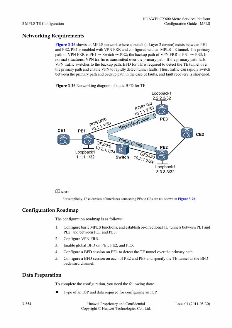
Networking RequirementsFigure 3-26 shows an MPLS network where a switch (a Layer 2 device) exists between PE1and PE2. PE1 is enabled with VPN FRR and configured with an MPLS TE tunnel. The primarypath of VPN FRR is PE1 → Switch → PE2; the backup path of VPN FRR is PE1 → PE3. Innormal situations, VPN traffic is transmitted over the primary path. If the primary path fails,VPN traffic switches to the backup path. BFD for TE is required to detect the TE tunnel overthe primary path and enable VPN to rapidly detect tunnel faults. Thus, traffic can rapidly switchbetween the primary path and backup path in the case of faults, and fault recovery is shortened.
Figure 3-26 Networking diagram of static BFD for TE
PE1
PE3
PE2
SwitchLoopback11.1.1.1/32
Loopback12.2.2.2/32
Loopback13.3.3.3/32
POS1/0/0
10.1.1.1/30
POS1/0/0
10.1.1.2/30
GE2/0/010.2.1.1/24 GE2/0/010.2.1.2/24
Primary tunnel
Secondary tunnel
CE2CE1
NOTE
For simplicity, IP addresses of interfaces connecting PEs to CEs are not shown in Figure 3-26.
Configuration RoadmapThe configuration roadmap is as follows:
1. Configure basic MPLS functions, and establish bi-directional TE tunnels between PE1 andPE2, and between PE1 and PE3.
2. Configure VPN FRR.3. Enable global BFD on PE1, PE2, and PE3.4. Configure a BFD session on PE1 to detect the TE tunnel over the primary path.5. Configure a BFD session on each of PE2 and PE3 and specify the TE tunnel as the BFD
backward channel.
Data PreparationTo complete the configuration, you need the following data:
l Type of an IGP and data required for configuring an IGP
3 MPLS TE ConfigurationHUAWEI CX600 Metro Services Platform
Configuration Guide - MPLS
3-354 Huawei Proprietary and ConfidentialCopyright © Huawei Technologies Co., Ltd.
Issue 01 (2011-05-30)
l BGP AS number and interfaces for BGP sessionsl MPLS LSR IDl Maximum reservable bandwidth and BC bandwidth of the outbound interfaces of links
along the tunnell Tunnel interface number, bandwidth for the tunnel, and explicit pathsl VPN instance name, RD, and route target (RT)l Tunnel policy namel Data required for configuring VPN FRR, such as IP prefix name and routing policy namel BFD name, local discriminator, and remote discriminator
Procedure
Step 1 Configure an IP address for each interface.
Configure an IP address for each interface as shown in Figure 3-26, create loopback interfaceson LSRs, and configure IP addresses of the loopback interfaces as MPLS LSR IDs, . Forconfiguration details, see the configuration file of this example.
Step 2 Configure the switch.
Configure the switch so that PE1 and PE2 can communicate with each other. Details for thisconfiguration procedure are not provided here.
Step 3 Configure an IGP.
Configure OSPF or IS-IS on each LSR so that PE1 and PE2, and PE1 and PE3 can communicatewith each other. Examples in this document use OSPF. For configuration details, see theconfiguration file of this example.
Step 4 Configure basic MPLS functions.
Configure the LSR ID and enable MPLS in the system view on each LSR, and enable MPLS inthe interface view. For configuration details, see the configuration file of this example.
Step 5 Configure basic MPLS TE functions.
Enable MPLS-TE and MPLS RSVP-TE in the MPLS and interface views on each LSR. Set themaximum reservable bandwidth for the MPLS TE on outbound interfaces of links along thetunnel to 100 Mbit/s and the BC bandwidth to 100 Mbit/s. For configuration details, see theconfiguration file of this example.
Step 6 Configure OSPF TE and CSPF.
Configure OSPF TE on each LSR and CSPF on PE1. For configuration details, see theconfiguration file of this example.
Step 7 Configure the tunnel interface.
# Specify explicit paths on PE1, PE2, and PE3. Two explicit paths are required on PE1.
# Configure PE1.
<PE1> system-view[PE1] explicit-path tope2[PE1-explicit-path-tope2] next hop 10.2.1.2[PE1-explicit-path-tope2] next hop 3.3.3.3[PE1-explicit-path-tope2] quit[PE1] explicit-path tope3
HUAWEI CX600 Metro Services PlatformConfiguration Guide - MPLS 3 MPLS TE Configuration
Issue 01 (2011-05-30) Huawei Proprietary and ConfidentialCopyright © Huawei Technologies Co., Ltd.
3-355
[PE1-explicit-path-tope3] next hop 10.1.1.2[PE1-explicit-path-tope3] next hop 2.2.2.2[PE1-explicit-path-tope3] quit
# Configure PE2.
<PE2> system-view[PE2] explicit-path tope1[PE2-explicit-path-tope1] next hop 10.2.1.1[PE2-explicit-path-tope1] next hop 1.1.1.1[PE2-explicit-path-tope1] quit
# Configure PE3.
<PE3> system-view[PE3] explicit-path tope1[PE3-explicit-path-tope1] next hop 10.1.1.1[PE3-explicit-path-tope1] next hop 1.1.1.1[PE3-explicit-path-tope1] quit
# Create tunnel interfaces on PE1, PE2, and PE3, specify explicit paths, and configure the tunnelbandwidth to 10 Mbit/s. Bind the tunnel to the specified VPN. Two tunnel interfaces must becreated on PE1.
# Configure PE1.
[PE1] interface tunnel 2/0/0[PE1-Tunnel2/0/0] ip address unnumbered interface loopback 1[PE1-Tunnel2/0/0] tunnel-protocol mpls te[PE1-Tunnel2/0/0] destination 3.3.3.3[PE1-Tunnel2/0/0] mpls te tunnel-id 200[PE1-Tunnel2/0/0] mpls te path explicit-path tope2[PE1-Tunnel2/0/0] mpls te bandwidth ct0 10000[PE1-Tunnel2/0/0] mpls te reserved-for-binding[PE1-Tunnel2/0/0] mpls te commit[PE1-Tunnel2/0/0] quit[PE1] interface tunnel 1/0/0[PE1-Tunnel1/0/0] ip address unnumbered interface loopback 1[PE1-Tunnel1/0/0] tunnel-protocol mpls te[PE1-Tunnel1/0/0] destination 2.2.2.2[PE1-Tunnel1/0/0] mpls te tunnel-id 100[PE1-Tunnel1/0/0] mpls te path explicit-path tope3[PE1-Tunnel1/0/0] mpls te bandwidth ct0 10000[PE1-Tunnel1/0/0] mpls te reserved-for-binding[PE1-Tunnel1/0/0] mpls te commit[PE1-Tunnel1/0/0] quit
# Configure PE2.
[PE2] interface tunnel 2/0/0[PE2-Tunnel2/0/0] ip address unnumbered interface loopback 1[PE2-Tunnel2/0/0] tunnel-protocol mpls te[PE2-Tunnel2/0/0] destination 1.1.1.1[PE2-Tunnel2/0/0] mpls te tunnel-id 200[PE2-Tunnel2/0/0] mpls te path explicit-path tope1[PE2-Tunnel2/0/0] mpls te bandwidth ct0 10000[PE2-Tunnel2/0/0] mpls te reserved-for-binding[PE2-Tunnel2/0/0] mpls te commit[PE2-Tunnel2/0/0] quit
# Configure PE3.
[PE3] interface tunnel 1/0/0[PE3-Tunnel1/0/0] ip address unnumbered interface loopback 1[PE3-Tunnel1/0/0] tunnel-protocol mpls te[PE3-Tunnel1/0/0] destination 1.1.1.1[PE3-Tunnel1/0/0] mpls te tunnel-id 100[PE3-Tunnel1/0/0] mpls te path explicit-path tope1[PE3-Tunnel1/0/0] mpls te bandwidth ct0 10000
3 MPLS TE ConfigurationHUAWEI CX600 Metro Services Platform
Configuration Guide - MPLS
3-356 Huawei Proprietary and ConfidentialCopyright © Huawei Technologies Co., Ltd.
Issue 01 (2011-05-30)
[PE3-Tunnel1/0/0] mpls te reserved-for-binding[PE3-Tunnel1/0/0] mpls te commit[PE3-Tunnel1/0/0] quit
# Run the display mpls te tunnel-interface tunnel interface-number command on PEs, andyou can see that the status of Tunnel 1/0/0 and Tunnel 2/0/0 on PE1, Tunnel 2/0/0 on PE2, andTunnel 1/0/0 on PE3 is "Up."
Step 8 Configure VPN FRR.
# Create VPN instances on PE1, PE2, and PE3 separately. Configure all VPN instance namesto vpn1, RDs to 100:1, 100:2, and 100:3 separately, and all RTs to 100:1. Configure CEs toaccess PEs. The configuration details are not provided here.
# Establish MP IBGP peer relationship between PE1 and PE2, and between PE1 and PE3. TheBGP AS number of PE1, PE2, and PE3 are 100. The loopback interface Loopback1 is used asthe interface to set up BGP sessions. The configuration details are not provided here.
# Configure tunnel policies for PE1, PE2, and PE3 and apply the policies to the VPN instances.
# Configure PE1.
[PE1] tunnel-policy policy1[PE1-tunnel-policy-policy1] tunnel binding destination 3.3.3.3 te tunnel 2/0/0[PE1-tunnel-policy-policy1] tunnel binding destination 2.2.2.2 te tunnel 1/0/0[PE1-tunnel-policy-policy1] quit[PE1] ip vpn-instance vpn1[PE1-ip-vpn-instance-vpn1] ipv4-family[PE1-ip-vpn-instance-vpn1-af-ipv4] tnl-policy policy1[PE1-ip-vpn-instance-vpn1-af-ipv4] quit[PE1-ip-vpn-instance-vpn1] quit
# Configure PE2.
[PE2] tunnel-policy policy1[PE2-tunnel-policy-policy1] tunnel binding destination 1.1.1.1 te tunnel 2/0/0[PE2-tunnel-policy-policy1] quit[PE2] ip vpn-instance vpn1[PE2-ip-vpn-instance-vpn1] ipv4-family[PE2-ip-vpn-instance-vpn1-af-ipv4] tnl-policy policy1[PE2-ip-vpn-instance-vpn1-af-ipv4] quit[PE2-ip-vpn-instance-vpn1] quit
# Configure PE3.
[PE3] tunnel-policy policy1[PE3-tunnel-policy-policy1] tunnel binding destination 1.1.1.1 te tunnel 1/0/0[PE3-tunnel-policy-policy1] quit[PE3] ip vpn-instance vpn1[PE3-ip-vpn-instance-vpn1] ipv4-family[PE3-ip-vpn-instance-vpn1-af-ipv4] tnl-policy policy1[PE3-ip-vpn-instance-vpn1-af-ipv4] quit[PE3-ip-vpn-instance-vpn1] quit
# Configure VPN FRR on PE1.
[PE1] ip ip-prefix vpn_frr_list permit 3.3.3.3 32[PE1] route-policy vpn_frr_rp permit node 10 [PE1-route-policy] if-match ip next-hop ip-prefix vpn_frr_list[PE1-route-policy] apply backup-nexthop 2.2.2.2[PE1-route-policy] quit[PE1] ip vpn-instance vpn1[PE1-vpn-instance-vpn1] ipv4-family[PE1-vpn-instance-vpn1-af-ipv4] vpn frr route-policy vpn_frr_rp[PE1-vpn-instance-vpn1-af-ipv4] quit[PE1-vpn-instance-vpn1] quit
HUAWEI CX600 Metro Services PlatformConfiguration Guide - MPLS 3 MPLS TE Configuration
Issue 01 (2011-05-30) Huawei Proprietary and ConfidentialCopyright © Huawei Technologies Co., Ltd.
3-357
# After the configuration, CEs can communicate with each other, and traffic passes through PE1,switch, and PE2. After the cable of any interface connecting PE1 and PE2 is plugged out, or theswitch or PE2 fails, VPN traffic switches to the backup path PE1 → PE3. Time taken in faultrecovery is close to the IGP convergence time.
Step 9 Configure BFD for TE.
# Configure a BFD session on PE1 to detect the TE tunnel of the primary path. Set the minimuminterval at which BFD packets are sent and received to 100 milliseconds and the local BFDdetection multiplier to 3.
[PE1] bfd[PE1-bfd] quit[PE1] bfd test bind mpls-te interface tunnel2/0/0[PE1-bfd-lsp-session-test] discriminator local 12[PE1-bfd-lsp-session-test] discriminator remote 21[PE1-bfd-lsp-session-test] min-tx-interval 100[PE1-bfd-lsp-session-test] min-rx-interval 100[PE1-bfd-lsp-session-test] detect-multiplier 3[PE1-bfd-lsp-session-test] process-pst[PE1-bfd-lsp-session-test] commit
# Configure a BFD session on PE2 and specify the TE tunnel as the BFD backward channel. Setthe minimum interval at which BFD packets are sent and received to 100 milliseconds and thelocal BFD detection multiplier to 3.
[PE2] bfd[PE2-bfd] quit[PE2] bfd test bind mpls-te interface tunnel2/0/0[PE2-bfd-lsp-session-test] discriminator local 21[PE2-bfd-lsp-session-test] discriminator remote 12[PE2-bfd-lsp-session-test] min-tx-interval 100[PE2-bfd-lsp-session-test] min-rx-interval 100[PE2-bfd-lsp-session-test] detect-multiplier 3[PE2-bfd-lsp-session-test] commit
# Run the display bfd session { all | discriminator discr-value | mpls-te | [ slot slot-id ][ verbose ] command on PE1 and PE2, and you can see that the status of the BFD sessions isUp.
Step 10 Verify the configuration.
Connect port 1 and port 2 on a tester to CE1 and CE2 respectively. Inject traffic from port 1 toport 2, and you can see that a fault can be recovered at milliseconds level.
----End
Configuration FilesNOTE
Configuration files of CE1, CE2, and switch are not listed here. Configurations related to CE accessing PEare also not listed.
l Configuration file of PE1# sysname PE1#ip vpn-instance vpn1 ipv4-family route-distinguisher 100:1 vpn frr route-policy vpn_frr_rp tnl-policy policy1 vpn-target 100:1 export-extcommunity vpn-target 100:1 import-extcommunity
3 MPLS TE ConfigurationHUAWEI CX600 Metro Services Platform
Configuration Guide - MPLS
3-358 Huawei Proprietary and ConfidentialCopyright © Huawei Technologies Co., Ltd.
Issue 01 (2011-05-30)
# bfd# mpls lsr-id 1.1.1.1 mpls mpls te mpls rsvp-te mpls te cspf# explicit-path tope2 next hop 10.2.1.2 next hop 3.3.3.3# explicit-path tope3 next hop 10.1.1.2 next hop 2.2.2.2#interface GigabitEthernet2/0/0 undo shutdown ip address 10.2.1.1 255.255.255.0 mpls mpls te mpls te bandwidth max-reservable-bandwidth 100000 mpls te bandwidth bc0 100000 mpls rsvp-te#interface Pos1/0/0 undo shutdown link-protocol ppp ip address 10.1.1.1 255.255.255.252 mpls mpls te mpls te bandwidth max-reservable-bandwidth 100000 mpls te bandwidth bc0 100000 mpls rsvp-te#interface LoopBack1 ip address 1.1.1.1 255.255.255.255#interface Tunnel1/0/0 ip address unnumbered interface LoopBack1 tunnel-protocol mpls te destination 2.2.2.2 mpls te tunnel-id 100 mpls te bandwidth ct0 10000 mpls te path explicit-path tope3 mpls te reserved-for-binding mpls te commit#interface Tunnel2/0/0 ip address unnumbered interface LoopBack1 tunnel-protocol mpls te destination 3.3.3.3 mpls te tunnel-id 200 mpls te bandwidth ct0 10000 mpls te path explicit-path tope2 mpls te reserved-for-binding mpls te commit#bgp 100 peer 2.2.2.2 as-number 100 peer 2.2.2.2 connect-interface LoopBack1 peer 3.3.3.3 as-number 100 peer 3.3.3.3 connect-interface LoopBack1 # ipv4-family unicast undo synchronization peer 2.2.2.2 enable peer 3.3.3.3 enable
HUAWEI CX600 Metro Services PlatformConfiguration Guide - MPLS 3 MPLS TE Configuration
Issue 01 (2011-05-30) Huawei Proprietary and ConfidentialCopyright © Huawei Technologies Co., Ltd.
3-359
# ipv4-family vpnv4 policy vpn-target peer 2.2.2.2 enable peer 3.3.3.3 enable# ipv4-family vpn-instance vpn1 import-route direct#ospf 1 opaque-capability enable area 0.0.0.0 network 10.1.1.0 0.0.0.3 network 10.2.1.0 0.0.0.255 network 1.1.1.1 0.0.0.0 mpls-te enable#route-policy vpn_frr_rp permit node 10 if-match ip next-hop ip-prefix vpn_frr_list apply backup-nexthop 2.2.2.2#ip ip-prefix vpn_frr_list permit 3.3.3.3 32#tunnel-policy policy1 tunnel binding destination 3.3.3.3 te Tunnel2/0/0 tunnel binding destination 2.2.2.2 te Tunnel1/0/0#bfd test bind mpls-te interface Tunnel2/0/0 discriminator local 12 discriminator remote 21 min-tx-interval 100 min-rx-interval 100 process-pst commit##return
l Configuration file of PE2# sysname PE2#ip vpn-instance vpn1 ipv4-family route-distinguisher 100:2 tnl-policy policy1 vpn-target 100:1 export-extcommunity vpn-target 100:1 import-extcommunity# bfd# mpls lsr-id 3.3.3.3 mpls mpls te mpls rsvp-te mpls te cspf# explicit-path tope1 next hop 10.2.1.1 next hop 1.1.1.1#interface GigabitEthernet2/0/0 undo shutdown ip address 10.2.1.2 255.255.255.0 mpls mpls te mpls te bandwidth max-reservable-bandwidth 100000 mpls te bandwidth bc0 100000 mpls rsvp-te#
3 MPLS TE ConfigurationHUAWEI CX600 Metro Services Platform
Configuration Guide - MPLS
3-360 Huawei Proprietary and ConfidentialCopyright © Huawei Technologies Co., Ltd.
Issue 01 (2011-05-30)
interface LoopBack1 ip address 3.3.3.3 255.255.255.255#interface Tunnel2/0/0 ip address unnumbered interface LoopBack1 tunnel-protocol mpls te destination 1.1.1.1 mpls te tunnel-id 200 mpls te bandwidth ct0 10000 mpls te path explicit-path tope1 mpls te reserved-for-binding mpls te commit#bgp 100 peer 1.1.1.1 as-number 100 peer 1.1.1.1 connect-interface LoopBack1 # ipv4-family unicast undo synchronization peer 1.1.1.1 enable# ipv4-family vpnv4 policy vpn-target peer 1.1.1.1 enable# ipv4-family vpn-instance vpn1 import-route direct#ospf 1 opaque-capability enable area 0.0.0.0 network 10.2.1.0 0.0.0.255 network 3.3.3.3 0.0.0.0 mpls-te enable#tunnel-policy policy1 tunnel binding destination 1.1.1.1 te Tunnel2/0/0#bfd test bind mpls-te interface Tunnel2/0/0 discriminator local 21 discriminator remote 12 min-tx-interval 100 min-rx-interval 100 commit#return
l Configuration file of PE3# sysname PE3#ip vpn-instance vpn1 ipv4-family route-distinguisher 100:3 tnl-policy policy1 vpn-target 100:1 export-extcommunity vpn-target 100:1 import-extcommunity# mpls lsr-id 2.2.2.2 mpls mpls te mpls rsvp-te mpls te cspf# explicit-path tope1 next hop 10.1.1.1 next hop 1.1.1.1#interface Pos1/0/0 undo shutdown
HUAWEI CX600 Metro Services PlatformConfiguration Guide - MPLS 3 MPLS TE Configuration
Issue 01 (2011-05-30) Huawei Proprietary and ConfidentialCopyright © Huawei Technologies Co., Ltd.
3-361
link-protocol ppp ip address 10.1.1.2 255.255.255.252 mpls mpls te mpls te bandwidth max-reservable-bandwidth 100000 mpls te bandwidth bc0 100000 mpls rsvp-te#interface LoopBack1 ip address 2.2.2.2 255.255.255.255#interface Tunnel1/0/0 ip address unnumbered interface LoopBack1 tunnel-protocol mpls te destination 1.1.1.1 mpls te tunnel-id 100 mpls te bandwidth ct0 10000 mpls te path explicit-path tope1 mpls te reserved-for-binding mpls te commit#bgp 100 peer 1.1.1.1 as-number 100 peer 1.1.1.1 connect-interface LoopBack1 # ipv4-family unicast undo synchronization peer 1.1.1.1 enable# ipv4-family vpnv4 policy vpn-target peer 1.1.1.1 enable# ipv4-family vpn-instance vpn1 import-route direct#ospf 1 opaque-capability enable area 0.0.0.0 network 10.1.1.0 0.0.0.3 network 2.2.2.2 0.0.0.0 mpls-te enable#tunnel-policy policy1 tunnel binding destination 1.1.1.1 te Tunnel1/0/0#return
3.26.26 Example for Configuring Dynamic BFD for CR-LSPThis section provides an example for configuring dynamic BFD for CR-LSP to ensure that hotstandby is enabled and a best-effect LSP is established in a tunnel.
Networking RequirementsFigure 3-27 is a networking diagram of CR-LSP hot standby. A TE tunnel is established betweenPE1 and PE2. The tunnel is enabled with hot standby and configured with a best-effort LSP. Ifthe primary CR-LSP fails, traffic can be switched to the backup CR-LSP. After the primary CR-LSP recovers, traffic can be switched back to the primary CR-LSP in 15 seconds. If both theprimary and backup CR-LSPs fail, traffic can be switched to the best-effort LSP.
Dynamic BFD for CR-LSP is required to detect the primary and backup CR-LSPs. After theconfiguration, the following objects should be achieved:
3 MPLS TE ConfigurationHUAWEI CX600 Metro Services Platform
Configuration Guide - MPLS
3-362 Huawei Proprietary and ConfidentialCopyright © Huawei Technologies Co., Ltd.
Issue 01 (2011-05-30)
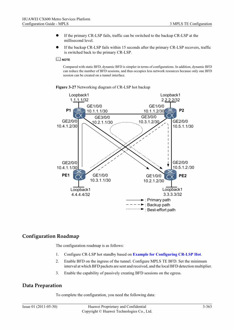
l If the primary CR-LSP fails, traffic can be switched to the backup CR-LSP at themillisecond level.
l If the backup CR-LSP fails within 15 seconds after the primary CR-LSP recovers, trafficis switched back to the primary CR-LSP.
NOTE
Compared with static BFD, dynamic BFD is simpler in terms of configurations. In addition, dynamic BFDcan reduce the number of BFD sessions, and thus occupies less network resources because only one BFDsession can be created on a tunnel interface.
Figure 3-27 Networking diagram of CR-LSP hot backup
Loopback11.1.1.1/32
Loopback12.2.2.2/32
Loopback14.4.4.4/32
Loopback13.3.3.3/32
GE2/0/010.4.1.1/30
GE2/0/010.4.1.2/30
GE1/0/010.1.1.1/30
GE1/0/010.1.1.2/30
GE3/0/010.3.1.2/30 GE2/0/0
10.5.1.1/30
GE2/0/010.5.1.2 /30
GE1/0/010.2.1.2/30
GE3/0/010.2.1.1/30
GE1/0/010.3.1.1/30
: Primary path: Backup path: Best-effort path
PE1 PE2
P1 P2
Configuration Roadmap
The configuration roadmap is as follows:
1. Configure CR-LSP hot standby based on Example for Configuring CR-LSP Hot.2. Enable BFD on the ingress of the tunnel. Configure MPLS TE BFD. Set the minimum
interval at which BFD packets are sent and received, and the local BFD detection multiplier.
3. Enable the capability of passively creating BFD sessions on the egress.
Data Preparation
To complete the configuration, you need the following data:
HUAWEI CX600 Metro Services PlatformConfiguration Guide - MPLS 3 MPLS TE Configuration
Issue 01 (2011-05-30) Huawei Proprietary and ConfidentialCopyright © Huawei Technologies Co., Ltd.
3-363
l Minimum intervals at which BFD packets are sent and received on the ingress (The defaultvalues are specified in the License.)
l Local BFD detection multiplier (The default values are specified in the License.)l For other data, see Example for Configuring CR-LSP Hot Standby
ProcedureStep 1 Configure CR-LSP hot standby.
Configure the primary CR-LSP, backup CR-LSP, and best-effort LSP based on Example forConfiguring CR-LSP Standby.
Step 2 Enable BFD on the ingress of the tunnel and configure MPLS TE BFD.
# Enable MPLS TE BFD on the tunnel interface of PE1. Set the minimum intervals at whichBFD packets are sent and received to 100 milliseconds and the local BFD detection multiplierto 3.
<PE1> system-view[PE1] bfd[PE1-bfd] quit[PE1] interface tunnel 1/0/0[PE1-Tunnel1/0/0] mpls te bfd enable[PE1-Tunenl1/0/0] mpls te bfd min-tx-interval 100 min-rx-interval 100 detect-multiplier 3[PE1-Tunenl1/0/0] mpls te commit
Step 3 Enable the capability of passively creating BFD sessions on the egress of the tunnel.<PE2> system-view[PE2] bfd[PE2-bfd] mpls-passive[PE2-bfd] quit
# Run the display bfd session discriminator local-discriminator-value command on PE1 andPE2, and you can see that the status of BFD sessions is Up.
[PE1] display bfd session mpls-te interface Tunnel 1/0/0 te-lsp--------------------------------------------------------------------------------Local Remote PeerIpAddr InterfaceName State Type--------------------------------------------------------------------------------8208 8217 3.3.3.3 Tunnel1/0/0 Up D_TE_LSP-------------------------------------------------------------------------------- Total UP/DOWN Session Number : 1/0
Step 4 Verify the configuration.
Connect port 1 and port 2 on a tester to PE1 and PE2 respectively. Inject traffic from port 1 toport 2. After the cable is removed from GE 2/0/0 on PE1 or P1, the fault recovers at themillisecond level.
After the cable is inserted into GE 2/0/0 and the cable is removed from GE 1/0/0 on PE1 in 15seconds, the fault recovers at the millisecond level.
----End
Configuration Filesl Configuration file of PE1
# sysname PE1# bfd
3 MPLS TE ConfigurationHUAWEI CX600 Metro Services Platform
Configuration Guide - MPLS
3-364 Huawei Proprietary and ConfidentialCopyright © Huawei Technologies Co., Ltd.
Issue 01 (2011-05-30)
# mpls lsr-id 4.4.4.4 mpls mpls te mpls rsvp-te mpls te cspf# explicit-path backup next hop 10.3.1.2 next hop 10.5.1.2 next hop 3.3.3.3# explicit-path main next hop 10.4.1.2 next hop 10.2.1.2 next hop 3.3.3.3#isis 1 cost-style wide network-entity 10.0000.0000.0004.00 traffic-eng level-1-2#interface GigabitEthernet1/0/0 ip address 10.3.1.1 255.255.255.252 isis enable 1 mpls mpls te mpls te bandwidth max-reservable-bandwidth 100000 mpls te bandwidth bc0 100000 mpls rsvp-te#interface GigabitEthernet2/0/0 ip address 10.4.1.1 255.255.255.252 isis enable 1 mpls mpls te mpls te bandwidth max-reservable-bandwidth 100000 mpls te bandwidth bc0 100000 mpls rsvp-te#interface LoopBack1 ip address 4.4.4.4 255.255.255.255 isis enable 1#interface Tunnel1/0/0 ip address unnumbered interface LoopBack1 tunnel-protocol mpls te destination 3.3.3.3 mpls te tunnel-id 100 mpls te bfd enable mpls te record-route mpls te bandwidth ct0 10000 mpls te path explicit-path main mpls te path explicit-path backup secondary mpls te backup hot-standby wtr 15 mpls te backup ordinary best-effort mpls te commit#return
l Configuration file of P1# sysname P1# mpls lsr-id 1.1.1.1 mpls mpls te mpls rsvp-te#isis 1
HUAWEI CX600 Metro Services PlatformConfiguration Guide - MPLS 3 MPLS TE Configuration
Issue 01 (2011-05-30) Huawei Proprietary and ConfidentialCopyright © Huawei Technologies Co., Ltd.
3-365
cost-style wide network-entity 10.0000.0000.0001.00 traffic-eng level-1-2#interface GigabitEthernet1/0/0 ip address 10.1.1.1 255.255.255.252 isis enable 1 mpls mpls te mpls rsvp-te#interface GigabitEthernet2/0/0 ip address 10.4.1.2 255.255.255.252 isis enable 1 mpls mpls te mpls rsvp-te#interface GigabitEthernet3/0/0 ip address 10.2.1.1 255.255.255.252 isis enable 1 mpls mpls te mpls te bandwidth max-reservable-bandwidth 100000 mpls te bandwidth bc0 100000 mpls rsvp-te#interface LoopBack1 ip address 1.1.1.1 255.255.255.255 isis enable 1#return
l Configuration file of P2# sysname P2# mpls lsr-id 2.2.2.2 mpls mpls te mpls rsvp-te#isis 1 cost-style wide network-entity 10.0000.0000.0002.00 traffic-eng level-1-2#interface GigabitEthernet1/0/0 ip address 10.1.1.2 255.255.255.252 isis enable 1 mpls mpls te mpls te bandwidth max-reservable-bandwidth 100000 mpls te bandwidth bc0 100000 mpls rsvp-te#interface GigabitEthernet2/0/0 ip address 10.5.1.1 255.255.255.252 isis enable 1 mpls mpls te mpls te bandwidth max-reservable-bandwidth 100000 mpls te bandwidth bc0 100000 mpls rsvp-te#interface GigabitEthernet3/0/0 ip address 10.3.1.2 255.255.255.252 isis enable 1 mpls mpls te
3 MPLS TE ConfigurationHUAWEI CX600 Metro Services Platform
Configuration Guide - MPLS
3-366 Huawei Proprietary and ConfidentialCopyright © Huawei Technologies Co., Ltd.
Issue 01 (2011-05-30)
mpls rsvp-te#interface LoopBack1 ip address 2.2.2.2 255.255.255.255 isis enable 1#return
l Configuration file of PE2# sysname PE2# bfd mpls-passive# mpls lsr-id 3.3.3.3 mpls mpls te mpls rsvp-te#isis 1 cost-style wide network-entity 10.0000.0000.0003.00 traffic-eng level-1-2#interface GigabitEthernet1/0/0 ip address 10.2.1.2 255.255.255.252 isis enable 1 mpls mpls te mpls rsvp-te#interface GigabitEthernet2/0/0 ip address 10.5.1.2 255.255.255.252 isis enable 1 mpls mpls te mpls rsvp-te#interface LoopBack1 ip address 3.3.3.3 255.255.255.255 isis enable 1#return
3.26.27 Example for Configuring Dynamic BFD for RSVPThis section provides an example for configuring dynamic BFD for RSVP for nodes to detectlink failure and perform the TE FRR switchover in the scenario where Layer 2 devices existbetween two nodes.
Networking Requirements
Figure 3-28 shows an MPLS network where a switch (a Layer 2 device) exists between P1 andP2. An MPLS TE tunnel is established between PE1 and PE2. TE FRR with P1 as PLR and PE2as MP is configured. The primary CR-LSP is PE1 --> P1 --> Switch --> P2 --> PE2; the bypassCR-LSP is P1 --> P3 --> PE2. In addition, each device is configured with RSVP GR.
GE 2/0/0 on P1 cannot receive RSVP Hello messages from its neighbors if either of the followingconditions are met:
l P2 is performing RSVP GR.
l The link or the switch between P1 and P2 fails.
HUAWEI CX600 Metro Services PlatformConfiguration Guide - MPLS 3 MPLS TE Configuration
Issue 01 (2011-05-30) Huawei Proprietary and ConfidentialCopyright © Huawei Technologies Co., Ltd.
3-367
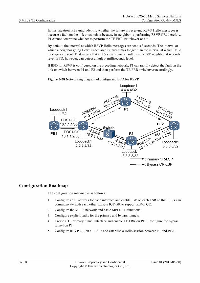
In this situation, P1 cannot identify whether the failure in receiving RSVP Hello messages isbecause a fault on the link or switch or because its neighbor is performing RSVP GR; therefore,P1 cannot determine whether to perform the TE FRR switchover or not.
By default, the interval at which RSVP Hello messages are sent is 3 seconds. The interval atwhich a neighbor going Down is declared is three times longer than the interval at which Hellomessages are sent. That means that an LSR can sense a fault on an RSVP neighbor at secondslevel. BFD, however, can detect a fault at milliseconds level.
If BFD for RSVP is configured on the preceding network, P1 can rapidly detect the fault on thelink or switch between P1 and P2 and then perform the TE FRR switchover accordingly.
Figure 3-28 Networking diagram of configuring BFD for RSVP
P1 PE2
P2
P3
Switch
Loopback12.2.2.2/32
Loopback15.5.5.5/32
Loopback14.4.4.4/32
Loopback13.3.3.3/32
POS3/0/0
10.3.1.1/30
POS1/0/0
10.3.1.2/30
GE2/0/010.2.1.1/24 GE2/0/010.2.1.2/24
POS1/0/0
10.4.1.2/30
POS1/0/0
10.4.1.1/30
POS2/0/010.5.1.2/30
POS2/0/010.5.1.1/30
: Bypass CR-LSP: Primary CR-LSP
PE1
POS1/0/010.1.1.1/30
POS1/0/010.1.1.2/30
Loopback11.1.1.1/32
Configuration RoadmapThe configuration roadmap is as follows:
1. Configure an IP address for each interface and enable IGP on each LSR so that LSRs cancommunicate with each other. Enable IGP GR to support RSVP GR.
2. Configure the MPLS network and basic MPLS TE functions.3. Configure explicit paths for the primary and bypass tunnels.4. Create a TE primary tunnel interface and enable TE FRR on PE1. Configure the bypass
tunnel on P1.5. Configure RSVP GR on all LSRs and establish a Hello session between P1 and PE2.
3 MPLS TE ConfigurationHUAWEI CX600 Metro Services Platform
Configuration Guide - MPLS
3-368 Huawei Proprietary and ConfidentialCopyright © Huawei Technologies Co., Ltd.
Issue 01 (2011-05-30)
NOTE
On a network configured with TE FRR, a Hello session is required between a PLR and an MP of thebypass tunnel if you want to configure RSVP GR. If the Hello session is not configured, when trafficswitches to the bypass tunnel because the primary tunnel fails, the primary tunnel turns Down if thePLR or MP performs RSVP GR.
6. Configure BFD for RSVP on P1 and P2.
Data Preparation
To complete the configuration, you need the following data:
l Type of an IGP and data required for configuring an IGPl MPLS LSR IDl Bandwidth attributes of the outbound interfaces of links along the tunnell Primary tunnel interface number, bandwidth for the primary tunnel, and explicit pathl Bypass tunnel interface number, bandwidth for the bypass tunnel, and explicit pathl Physical interfaces to be protected by the bypass tunnell Minimum intervals at which BFD packets are sent and received (The default values are
specified in the License.)l Local BFD detection multiplier (The default values are specified in the License.)
Procedure
Step 1 Configure an IP address for each interface.
Configure an IP address for each interface as shown in Figure 3-28, create loopback interfaceson LSRs, and then configure the IP addresses of the loopback interfaces as MPLS LSR IDs. Forconfiguration details, see the configuration file of this example.
Step 2 Configure the switch.
Configure the switch so that P1 and P2 can communicate with each other. Details for thisconfiguration procedure are not provided here.
Step 3 Configure an IGP and IGP GR.
Configure OSPF or IS-IS on each LSR so that LSRs can communicate with each other. ConfigureIGP GR to support RSVP GR. Examples in this document use OSPF. For configuration details,see the configuration file of this example.
Step 4 Configuring basic MPLS functions.
Configure the LSR ID and enable MPLS in the system view on each LSR, and enable MPLS inthe interface view. For configuration details, see the configuration file of this example.
Step 5 Configure basic MPLS TE functions.
Enable MPLS-TE and MPLS RSVP-TE in the MPLS and interface views on each LSR. Set themaximum reservable bandwidth for the outbound interfaces of links along the tunnel to 100Mbit/s and the BC0 bandwidth to 100 Mbit/s. For configuration details, see the configurationfile of this example.
Step 6 Configure OSPF TE and CSPF.
HUAWEI CX600 Metro Services PlatformConfiguration Guide - MPLS 3 MPLS TE Configuration
Issue 01 (2011-05-30) Huawei Proprietary and ConfidentialCopyright © Huawei Technologies Co., Ltd.
3-369
Enable OSPF TE on each node and configure CSPF on PE1 and PE2. For configuration details,see Configuring the RSVP-TE Tunnel.
Step 7 Configure the primary tunnel.
# Specify an explicit path for the primary tunnel on PE1.
<PE1> system-view[PE1] explicit-path tope2[PE1-explicit-path-tope2] next hop 10.1.1.2[PE1-explicit-path-tope2] next hop 10.2.1.2[PE1-explicit-path-tope2] next hop 10.4.1.2[PE1-explicit-path-tope2] next hop 5.5.5.5[PE1-explicit-path-tope2] quit
# Create a tunnel interface on PE1, specify an explicit path, set the tunnel bandwidth to 10 Mbit/s, and enable TE FRR.
[PE1] interface tunnel 1/0/0[PE1-Tunnel1/0/0] ip address unnumbered interface loopback 1[PE1-Tunnel1/0/0] tunnel-protocol mpls te[PE1-Tunnel1/0/0] destination 5.5.5.5[PE1-Tunnel1/0/0] mpls te tunnel-id 100[PE1-Tunnel1/0/0] mpls te path explicit-path tope2[PE1-Tunnel1/0/0] mpls te bandwidth ct0 10000[PE1-Tunnel1/0/0] mpls te fast-reroute[PE1-Tunnel1/0/0] mpls te commit[PE1-Tunnel1/0/0] quit
# Run the display mpls te tunnel-interface tunnel interface-number command on PE1, andyou can see that the status of tunnel 1/0/0 on PE1 is "Up."
Step 8 Configure the bypass tunnel.
# Specify the explicit path for the bypass tunnel on P1.
<P1> system-view[P1] explicit-path tope2[P1-explicit-path-tope2] next hop 10.3.1.2[P1-explicit-path-tope2] next hop 10.5.1.2[P1-explicit-path-tope2] next hop 5.5.5.5[P1-explicit-path-tope2] quit
# Configure a bypass tunnel interface and specify an explicit path for the bypass tunnel. Set thetunnel bandwidth to 20 Mbit/s and the protected bandwidth to 10 Mbit/s. Specify the physicalinterface to be protected by the bypass tunnel.
[P1] interface tunnel 3/0/0[P1-Tunnel3/0/0] ip address unnumbered interface loopback 1[P1-Tunnel3/0/0] tunnel-protocol mpls te[P1-Tunnel3/0/0] destination 5.5.5.5[P1-Tunnel3/0/0] mpls te tunnel-id 300[P1-Tunnel3/0/0] mpls te path explicit-path tope2[P1-Tunnel3/0/0] mpls te bandwidth ct0 20000[P1-Tunnel3/0/0] mpls te bypass-tunnel[P1-Tunnel3/0/0] mpls te protected-interface gigabitethernet 2/0/0[P1-Tunnel3/0/0] mpls te commit[P1-Tunnel3/0/0] quit
Step 9 Configuring RSVP GR.
# Configure RSVP GR on all LSRs and establish Hello sessions between P1 and PE2.
# Configure PE1.
[PE1] mpls[PE1-mpls] mpls rsvp-te hello
3 MPLS TE ConfigurationHUAWEI CX600 Metro Services Platform
Configuration Guide - MPLS
3-370 Huawei Proprietary and ConfidentialCopyright © Huawei Technologies Co., Ltd.
Issue 01 (2011-05-30)
[PE1-mpls] mpls rsvp-te hello full-gr[PE1-mpls] quit[PE1] interface pos1/0/0[PE1-Pos1/0/0] mpls rsvp-te hello
# Configure P1.
[P1] mpls[P1-mpls] mpls rsvp-te hello[P1-mpls] mpls rsvp-te hello full-gr[P1-mpls] mpls rsvp-te hello nodeid-session 5.5.5.5[P1-mpls] quit[P1] interface pos1/0/0[P1-Pos1/0/0] mpls rsvp-te hello[P1-Pos1/0/0] quit[P1] interface gigabitethernet 2/0/0[P1-GigabitEthernet2/0/0] mpls rsvp-te hello[P1-GigabitEthernet2/0/0] quit[P1] interface pos 3/0/0[P1-Pos3/0/0] mpls rsvp-te hello[P1-Pos3/0/0] quit
# Configure P2.
[P2] mpls[P2-mpls] mpls rsvp-te hello[P2-mpls] mpls rsvp-te hello full-gr[P2-mpls] quit[P2] interface pos1/0/0[P2-Pos1/0/0] mpls rsvp-te hello[P2-Pos1/0/0] quit[P2] interface gigabitethernet 2/0/0[P2-GigabitEthernet2/0/0] mpls rsvp-te hello[P2-GigabitEthernet2/0/0] quit
# Configure P3.
[P3] mpls[P3-mpls] mpls rsvp-te hello[P3-mpls] mpls rsvp-te hello full-gr[P3-mpls] quit[P3] interface pos1/0/0[P3-Pos1/0/0] mpls rsvp-te hello[P3-Pos1/0/0] quit[P3] interface pos 2/0/0[P3-Pos2/0/0] mpls rsvp-te hello[P3-Pos2/0/0] quit
# Configure PE2.
[PE2] mpls[PE2-mpls] mpls rsvp-te hello[PE2-mpls] mpls rsvp-te hello full-gr[PE2-mpls] mpls rsvp-te hello nodeid-session 2.2.2.2[PE2-mpls] quit[PE2] interface pos1/0/0[PE2-Pos1/0/0] mpls rsvp-te hello[PE2-Pos1/0/0] quit[PE2] interface pos 2/0/0[PE2-Pos2/0/0] mpls rsvp-te hello[PE2-Pos2/0/0] quit
Step 10 Configure BFD for RSVP.
# Enable BFD for RSVP on GE 2/0/0 on P1 and P2. Set the minimum interval at which BFDpackets are sent and received and the local BFD detection multiplier.
# Configure P1.
[P1] bfd
HUAWEI CX600 Metro Services PlatformConfiguration Guide - MPLS 3 MPLS TE Configuration
Issue 01 (2011-05-30) Huawei Proprietary and ConfidentialCopyright © Huawei Technologies Co., Ltd.
3-371
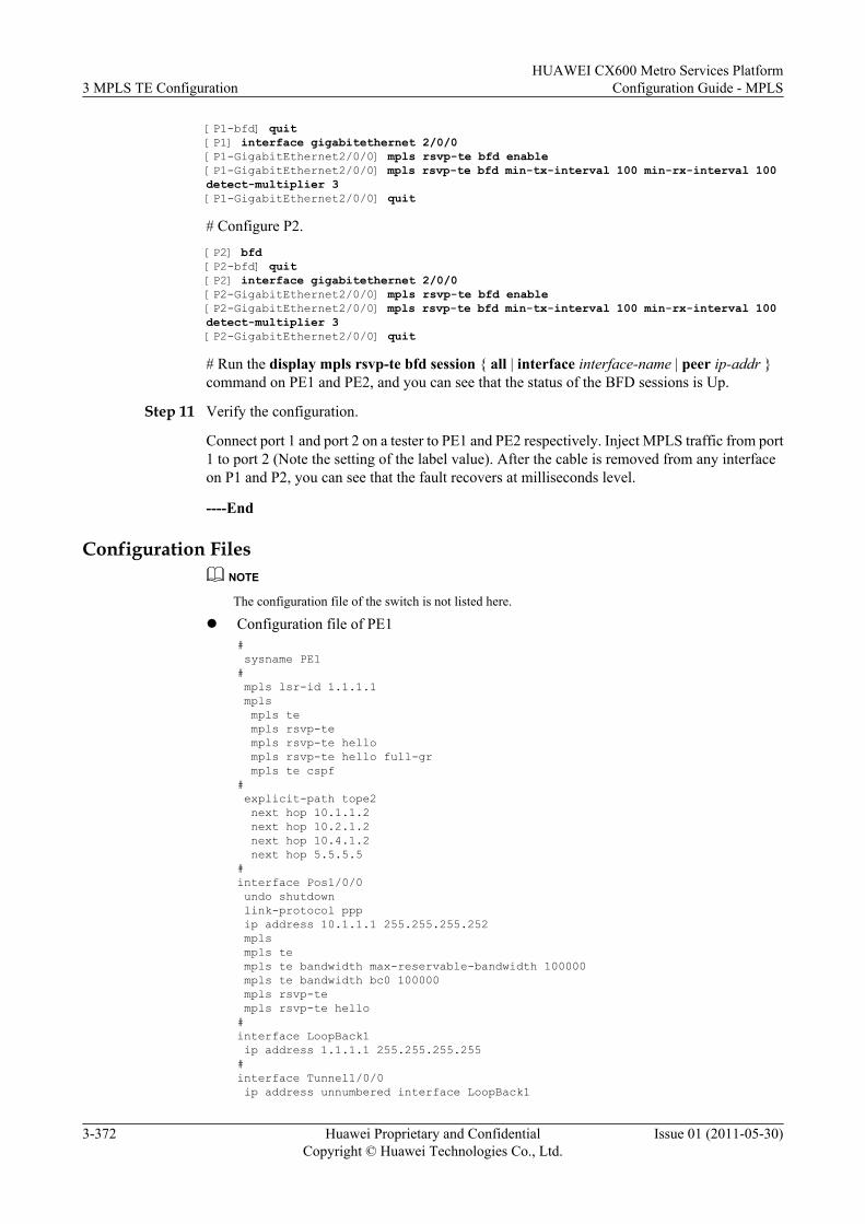
[P1-bfd] quit[P1] interface gigabitethernet 2/0/0[P1-GigabitEthernet2/0/0] mpls rsvp-te bfd enable[P1-GigabitEthernet2/0/0] mpls rsvp-te bfd min-tx-interval 100 min-rx-interval 100 detect-multiplier 3[P1-GigabitEthernet2/0/0] quit
# Configure P2.[P2] bfd[P2-bfd] quit[P2] interface gigabitethernet 2/0/0[P2-GigabitEthernet2/0/0] mpls rsvp-te bfd enable[P2-GigabitEthernet2/0/0] mpls rsvp-te bfd min-tx-interval 100 min-rx-interval 100 detect-multiplier 3[P2-GigabitEthernet2/0/0] quit
# Run the display mpls rsvp-te bfd session { all | interface interface-name | peer ip-addr }command on PE1 and PE2, and you can see that the status of the BFD sessions is Up.
Step 11 Verify the configuration.
Connect port 1 and port 2 on a tester to PE1 and PE2 respectively. Inject MPLS traffic from port1 to port 2 (Note the setting of the label value). After the cable is removed from any interfaceon P1 and P2, you can see that the fault recovers at milliseconds level.
----End
Configuration FilesNOTE
The configuration file of the switch is not listed here.
l Configuration file of PE1# sysname PE1# mpls lsr-id 1.1.1.1 mpls mpls te mpls rsvp-te mpls rsvp-te hello mpls rsvp-te hello full-gr mpls te cspf# explicit-path tope2 next hop 10.1.1.2 next hop 10.2.1.2 next hop 10.4.1.2 next hop 5.5.5.5#interface Pos1/0/0 undo shutdown link-protocol ppp ip address 10.1.1.1 255.255.255.252 mpls mpls te mpls te bandwidth max-reservable-bandwidth 100000 mpls te bandwidth bc0 100000 mpls rsvp-te mpls rsvp-te hello#interface LoopBack1 ip address 1.1.1.1 255.255.255.255#interface Tunnel1/0/0 ip address unnumbered interface LoopBack1
3 MPLS TE ConfigurationHUAWEI CX600 Metro Services Platform
Configuration Guide - MPLS
3-372 Huawei Proprietary and ConfidentialCopyright © Huawei Technologies Co., Ltd.
Issue 01 (2011-05-30)
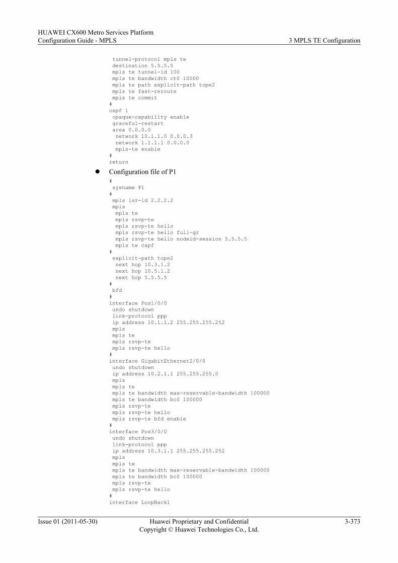
tunnel-protocol mpls te destination 5.5.5.5 mpls te tunnel-id 100 mpls te bandwidth ct0 10000 mpls te path explicit-path tope2 mpls te fast-reroute mpls te commit#ospf 1 opaque-capability enable graceful-restart area 0.0.0.0 network 10.1.1.0 0.0.0.3 network 1.1.1.1 0.0.0.0 mpls-te enable#return
l Configuration file of P1# sysname P1# mpls lsr-id 2.2.2.2 mpls mpls te mpls rsvp-te mpls rsvp-te hello mpls rsvp-te hello full-gr mpls rsvp-te hello nodeid-session 5.5.5.5 mpls te cspf# explicit-path tope2 next hop 10.3.1.2 next hop 10.5.1.2 next hop 5.5.5.5# bfd#interface Pos1/0/0 undo shutdown link-protocol ppp ip address 10.1.1.2 255.255.255.252 mpls mpls te mpls rsvp-te mpls rsvp-te hello#interface GigabitEthernet2/0/0 undo shutdown ip address 10.2.1.1 255.255.255.0 mpls mpls te mpls te bandwidth max-reservable-bandwidth 100000 mpls te bandwidth bc0 100000 mpls rsvp-te mpls rsvp-te hello mpls rsvp-te bfd enable#interface Pos3/0/0 undo shutdown link-protocol ppp ip address 10.3.1.1 255.255.255.252 mpls mpls te mpls te bandwidth max-reservable-bandwidth 100000 mpls te bandwidth bc0 100000 mpls rsvp-te mpls rsvp-te hello#interface LoopBack1
HUAWEI CX600 Metro Services PlatformConfiguration Guide - MPLS 3 MPLS TE Configuration
Issue 01 (2011-05-30) Huawei Proprietary and ConfidentialCopyright © Huawei Technologies Co., Ltd.
3-373
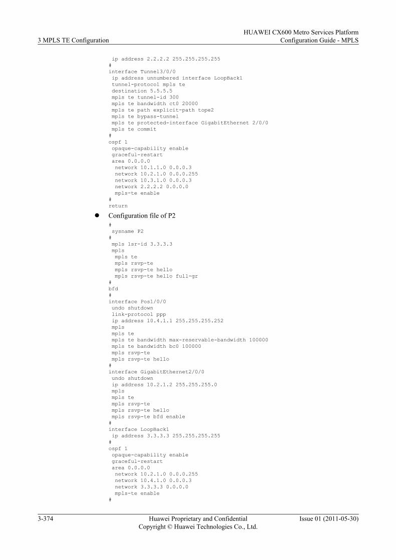
ip address 2.2.2.2 255.255.255.255#interface Tunnel3/0/0 ip address unnumbered interface LoopBack1 tunnel-protocol mpls te destination 5.5.5.5 mpls te tunnel-id 300 mpls te bandwidth ct0 20000 mpls te path explicit-path tope2 mpls te bypass-tunnel mpls te protected-interface GigabitEthernet 2/0/0 mpls te commit#ospf 1 opaque-capability enable graceful-restart area 0.0.0.0 network 10.1.1.0 0.0.0.3 network 10.2.1.0 0.0.0.255 network 10.3.1.0 0.0.0.3 network 2.2.2.2 0.0.0.0 mpls-te enable#return
l Configuration file of P2# sysname P2# mpls lsr-id 3.3.3.3 mpls mpls te mpls rsvp-te mpls rsvp-te hello mpls rsvp-te hello full-gr#bfd#interface Pos1/0/0 undo shutdown link-protocol ppp ip address 10.4.1.1 255.255.255.252 mpls mpls te mpls te bandwidth max-reservable-bandwidth 100000 mpls te bandwidth bc0 100000 mpls rsvp-te mpls rsvp-te hello#interface GigabitEthernet2/0/0 undo shutdown ip address 10.2.1.2 255.255.255.0 mpls mpls te mpls rsvp-te mpls rsvp-te hello mpls rsvp-te bfd enable#interface LoopBack1 ip address 3.3.3.3 255.255.255.255#ospf 1 opaque-capability enable graceful-restart area 0.0.0.0 network 10.2.1.0 0.0.0.255 network 10.4.1.0 0.0.0.3 network 3.3.3.3 0.0.0.0 mpls-te enable#
3 MPLS TE ConfigurationHUAWEI CX600 Metro Services Platform
Configuration Guide - MPLS
3-374 Huawei Proprietary and ConfidentialCopyright © Huawei Technologies Co., Ltd.
Issue 01 (2011-05-30)
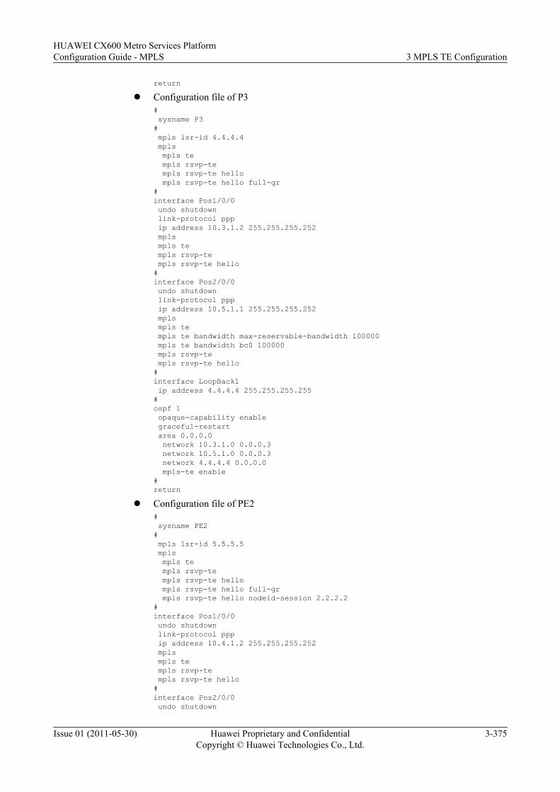
returnl Configuration file of P3
# sysname P3# mpls lsr-id 4.4.4.4 mpls mpls te mpls rsvp-te mpls rsvp-te hello mpls rsvp-te hello full-gr#interface Pos1/0/0 undo shutdown link-protocol ppp ip address 10.3.1.2 255.255.255.252 mpls mpls te mpls rsvp-te mpls rsvp-te hello#interface Pos2/0/0 undo shutdown link-protocol ppp ip address 10.5.1.1 255.255.255.252 mpls mpls te mpls te bandwidth max-reservable-bandwidth 100000 mpls te bandwidth bc0 100000 mpls rsvp-te mpls rsvp-te hello#interface LoopBack1 ip address 4.4.4.4 255.255.255.255#ospf 1 opaque-capability enable graceful-restart area 0.0.0.0 network 10.3.1.0 0.0.0.3 network 10.5.1.0 0.0.0.3 network 4.4.4.4 0.0.0.0 mpls-te enable#return
l Configuration file of PE2# sysname PE2# mpls lsr-id 5.5.5.5 mpls mpls te mpls rsvp-te mpls rsvp-te hello mpls rsvp-te hello full-gr mpls rsvp-te hello nodeid-session 2.2.2.2#interface Pos1/0/0 undo shutdown link-protocol ppp ip address 10.4.1.2 255.255.255.252 mpls mpls te mpls rsvp-te mpls rsvp-te hello#interface Pos2/0/0 undo shutdown
HUAWEI CX600 Metro Services PlatformConfiguration Guide - MPLS 3 MPLS TE Configuration
Issue 01 (2011-05-30) Huawei Proprietary and ConfidentialCopyright © Huawei Technologies Co., Ltd.
3-375
link-protocol ppp ip address 10.5.1.2 255.255.255.252 mpls mpls te mpls rsvp-te mpls rsvp-te hello#interface LoopBack1 ip address 5.5.5.5 255.255.255.255#ospf 1 opaque-capability enable graceful-restart area 0.0.0.0 network 10.4.1.0 0.0.0.3 network 10.5.1.0 0.0.0.3 network 5.5.5.5 0.0.0.0 mpls-te enable#return
3.26.28 Example for Configuring LDP over TEThis section provides an example for configuring LDP over TE.
Networking RequirementsOn the network shown in Figure 3-29, LDP is run between LSR A and LSR B, and betweenLSR D and LSR E. LDP does not run between LSR B, LSR C and LSR D. RSVP tunnels fromLSR B to LSR D and from LSR D to LSR B are established. It is required that traffic betweenLSR A and LSR E pass transmitted over tunnels.
LDP is not run between LSR B, LSR C, and LSR D.
Figure 3-29 Networking diagram of LDP over TE configuration
Loopback15.5.5.5/32
Loopback14.4.4.4/32
Loopback12.2.2.2/32
LSRE
LSRC
POS2/0/020.1.1.1/24
POS1/0/020.1.1.2/24
POS2/0/030.1.1.1/24
LSRA
LSRB
POS1/0/010.1.1.1/24
POS1/0/010.1.1.2/24
Loopback11.1.1.1/32
Loopback13.3.3.3/32
LSRDPOS1/0/0
30.1.1.2/24 POS2/0/040.1.1.2/24
POS1/0/040.1.1.1/24
Configuration RoadmapThe configuration roadmap is as follows:
1. Configure IP addresses for interfaces on each LSR, configure loopback address as the LSRIDs, and enable IGP.
3 MPLS TE ConfigurationHUAWEI CX600 Metro Services Platform
Configuration Guide - MPLS
3-376 Huawei Proprietary and ConfidentialCopyright © Huawei Technologies Co., Ltd.
Issue 01 (2011-05-30)
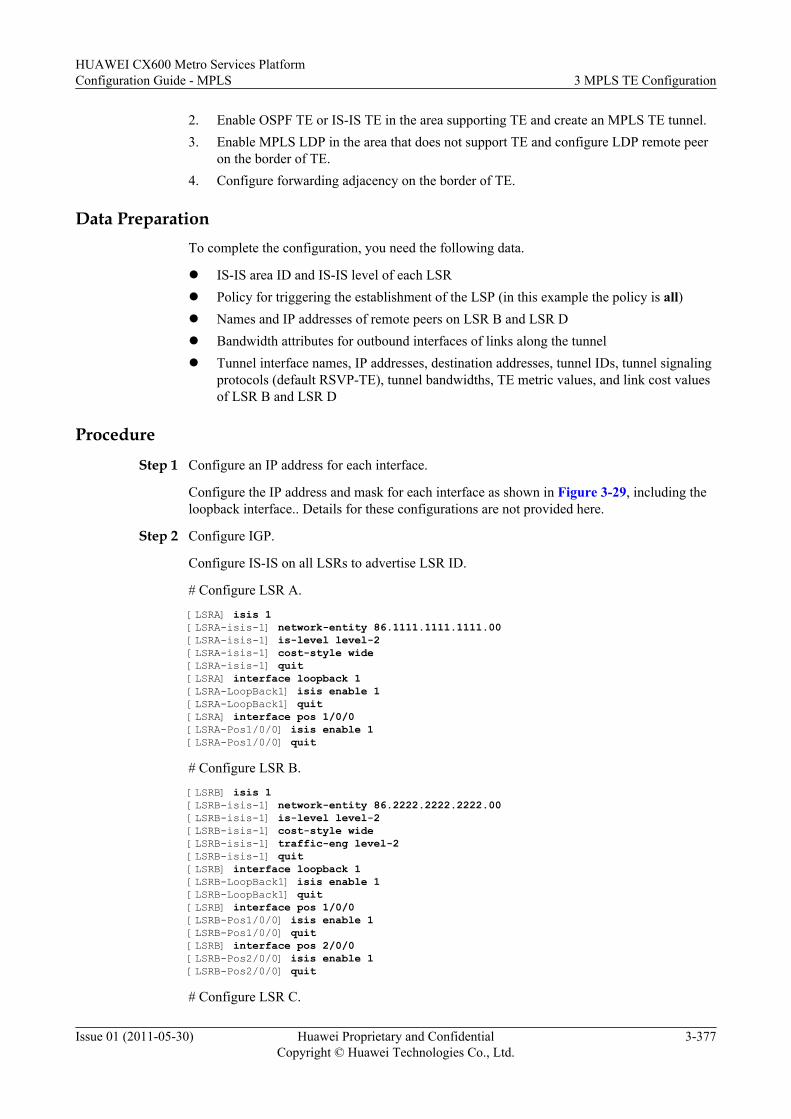
2. Enable OSPF TE or IS-IS TE in the area supporting TE and create an MPLS TE tunnel.3. Enable MPLS LDP in the area that does not support TE and configure LDP remote peer
on the border of TE.4. Configure forwarding adjacency on the border of TE.
Data PreparationTo complete the configuration, you need the following data.
l IS-IS area ID and IS-IS level of each LSRl Policy for triggering the establishment of the LSP (in this example the policy is all)l Names and IP addresses of remote peers on LSR B and LSR Dl Bandwidth attributes for outbound interfaces of links along the tunnell Tunnel interface names, IP addresses, destination addresses, tunnel IDs, tunnel signaling
protocols (default RSVP-TE), tunnel bandwidths, TE metric values, and link cost valuesof LSR B and LSR D
Procedure
Step 1 Configure an IP address for each interface.
Configure the IP address and mask for each interface as shown in Figure 3-29, including theloopback interface.. Details for these configurations are not provided here.
Step 2 Configure IGP.
Configure IS-IS on all LSRs to advertise LSR ID.
# Configure LSR A.
[LSRA] isis 1[LSRA-isis-1] network-entity 86.1111.1111.1111.00[LSRA-isis-1] is-level level-2[LSRA-isis-1] cost-style wide[LSRA-isis-1] quit[LSRA] interface loopback 1[LSRA-LoopBack1] isis enable 1[LSRA-LoopBack1] quit[LSRA] interface pos 1/0/0[LSRA-Pos1/0/0] isis enable 1[LSRA-Pos1/0/0] quit
# Configure LSR B.
[LSRB] isis 1[LSRB-isis-1] network-entity 86.2222.2222.2222.00[LSRB-isis-1] is-level level-2[LSRB-isis-1] cost-style wide[LSRB-isis-1] traffic-eng level-2[LSRB-isis-1] quit[LSRB] interface loopback 1[LSRB-LoopBack1] isis enable 1[LSRB-LoopBack1] quit[LSRB] interface pos 1/0/0[LSRB-Pos1/0/0] isis enable 1[LSRB-Pos1/0/0] quit[LSRB] interface pos 2/0/0[LSRB-Pos2/0/0] isis enable 1[LSRB-Pos2/0/0] quit
# Configure LSR C.
HUAWEI CX600 Metro Services PlatformConfiguration Guide - MPLS 3 MPLS TE Configuration
Issue 01 (2011-05-30) Huawei Proprietary and ConfidentialCopyright © Huawei Technologies Co., Ltd.
3-377
[LSRC] isis 1[LSRC-isis-1] network-entity 86.3333.3333.3333.00[LSRC-isis-1] is-level level-2[LSRC-isis-1] cost-style wide[LSRC-isis-1] traffic-eng level-2[LSRC-isis-1] quit[LSRC] interface loopback 1[LSRC-LoopBack1] isis enable 1[LSRC-LoopBack1] quit[LSRC] interface pos 1/0/0[LSRC-Pos1/0/0] isis enable 1[LSRC-Pos1/0/0] quit[LSRC] interface pos 2/0/0[LSRC-Pos2/0/0] isis enable 1[LSRC-Pos2/0/0] quit
# Configure LSR D.
[LSRD] isis 1[LSRD-isis-1] network-entity 86.4444.4444.4444.00[LSRD-isis-1] is-level level-2[LSRD-isis-1] cost-style wide[LSRD-isis-1] traffic-eng level-2[LSRD-isis-1] quit[LSRD] interface loopback 1[LSRD-LoopBack1] isis enable 1[LSRD-LoopBack1] quit[LSRD] interface pos 1/0/0[LSRD-Pos1/0/0] isis enable 1[LSRD-Pos1/0/0] quit[LSRD] interface pos 2/0/0[LSRD-Pos2/0/0] isis enable 1[LSRD-Pos2/0/0] quit
# Configure LSR E.
[LSRE] isis 1[LSRE-isis-1] network-entity 86.5555.5555.5555.00[LSRE-isis-1] is-level level-2[LSRE-isis-1] cost-style wide[LSRE-isis-1] quit[LSRE] interface loopback 1[LSRE-LoopBack1] isis enable 1[LSRE-LoopBack1] quit[LSRE] interface pos 1/0/0[LSRE-Pos1/0/0] isis enable 1[LSRE-Pos1/0/0] quit
Step 3 Configure basic MPLS functions on all LSRs, enable LDP on LSR A, LSR B, LSR D, and LSRE, and enable RSVP on LSR B, LSR C, and LSR D.
# Configure LSR A.
[LSRA] mpls lsr-id 1.1.1.1[LSRA] mpls[LSRA-mpls] quit[LSRA] mpls ldp[LSRA-mpls-ldp] quit[LSRA] interface pos 1/0/0[LSRA-Pos1/0/0] mpls[LSRA-Pos1/0/0] mpls ldp[LSRA-Pos1/0/0] quit
# Configure LSR B.
[LSRB] mpls lsr-id 2.2.2.2[LSRB] mpls[LSRB-mpls] mpls te[LSRB-mpls] mpls rsvp-te[LSRB-mpls] mpls te cspf
3 MPLS TE ConfigurationHUAWEI CX600 Metro Services Platform
Configuration Guide - MPLS
3-378 Huawei Proprietary and ConfidentialCopyright © Huawei Technologies Co., Ltd.
Issue 01 (2011-05-30)
[LSRB-mpls] quit[LSRB] mpls ldp[LSRB-mpls-ldp] quit[LSRB] interface pos 1/0/0[LSRB-Pos1/0/0] mpls[LSRB-Pos1/0/0] mpls ldp[LSRB-Pos1/0/0] quit[LSRB] interface pos 2/0/0[LSRB-Pos2/0/0] mpls[LSRB-Pos2/0/0] mpls te[LSRB-Pos2/0/0] mpls rsvp-te[LSRB-Pos2/0/0] quit
# Configure LSR C.
[LSRC] mpls lsr-id 3.3.3.3[LSRC] mpls[LSRC-mpls] mpls te[LSRC-mpls] mpls rsvp-te[LSRC-mpls] quit[LSRC] interface pos 1/0/0[LSRC-Pos1/0/0] mpls[LSRC-Pos1/0/0] mpls te[LSRC-Pos1/0/0] mpls rsvp-te[LSRC-Pos1/0/0] quit[LSRC] interface pos 2/0/0[LSRC-Pos2/0/0] mpls[LSRC-Pos2/0/0] mpls te[LSRC-Pos2/0/0] mpls rsvp-te[LSRC-Pos2/0/0] quit
# Configure LSR D.
[LSRD] mpls lsr-id 4.4.4.4[LSRD] mpls[LSRD-mpls] mpls te[LSRD-mpls] mpls rsvp-te[LSRD-mpls] mpls te cspf[LSRD-mpls] quit[LSRD] mpls ldp[LSRD-mpls-ldp] quit[LSRD] interface pos 1/0/0[LSRD-Pos1/0/0] mpls[LSRD-Pos1/0/0] mpls te[LSRD-Pos1/0/0] mpls rsvp-te[LSRD-Pos1/0/0] quit[LSRD] interface pos 2/0/0[LSRD-Pos2/0/0] mpls[LSRD-Pos2/0/0] mpls ldp[LSRD-Pos2/0/0] quit
# Configure LSR E.
[LSRE] mpls lsr-id 5.5.5.5[LSRE] mpls[LSRE-mpls] quit[LSRE] mpls ldp[LSRE-mpls-ldp] quit[LSRE] interface pos 1/0/0[LSRE-Pos1/0/0] mpls[LSRE-Pos1/0/0] mpls ldp[LSRE-Pos1/0/0] quit
After the configuration, the LDP session is established successfully between LSR A and LSRB, and between LSR D and LSR E.
Run the display mpls ldp session command on LSR A, LSR B, LSR D, and LSR E, and youcan view whether LDP sessions are established.
HUAWEI CX600 Metro Services PlatformConfiguration Guide - MPLS 3 MPLS TE Configuration
Issue 01 (2011-05-30) Huawei Proprietary and ConfidentialCopyright © Huawei Technologies Co., Ltd.
3-379
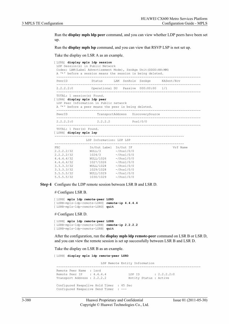
Run the display mpls ldp peer command, and you can view whether LDP peers have been setup.
Run the display mpls lsp command, and you can view that RSVP LSP is not set up.
Take the display on LSR A as an example.
[LSRA] display mpls ldp session LDP Session(s) in Public Network Codes: LAM(Label Advertisement Mode), SsnAge Unit(DDDD:HH:MM) A '*' before a session means the session is being deleted. ------------------------------------------------------------------------------ PeerID Status LAM SsnRole SsnAge KASent/Rcv ------------------------------------------------------------------------------ 2.2.2.2:0 Operational DU Passive 000:00:00 1/1 ------------------------------------------------------------------------------ TOTAL: 1 session(s) Found.[LSRA] display mpls ldp peer LDP Peer Information in Public network A '*' before a peer means the peer is being deleted. ------------------------------------------------------------------------------ PeerID TransportAddress DiscoverySource ------------------------------------------------------------------------------ 2.2.2.2:0 2.2.2.2 Pos1/0/0 ------------------------------------------------------------------------------ TOTAL: 1 Peer(s) Found.[LSRA] display mpls lsp---------------------------------------------------------------------- LSP Information: LDP LSP----------------------------------------------------------------------FEC In/Out Label In/Out IF Vrf Name2.2.2.2/32 NULL/3 -/Pos1/0/02.2.2.2/32 1024/3 -/Pos1/0/04.4.4.4/32 NULL/1026 -/Pos1/0/04.4.4.4/32 1027/1026 -/Pos1/0/03.3.3.3/32 NULL/1028 -/Pos1/0/03.3.3.3/32 1029/1028 -/Pos1/0/05.5.5.5/32 NULL/1029 -/Pos1/0/05.5.5.5/32 1030/1029 -/Pos1/0/0
Step 4 Configure the LDP remote session between LSR B and LSR D.
# Configure LSR B.
[LSRB] mpls ldp remote-peer LSRD[LSRB-mpls-ldp-remote-LSRD] remote-ip 4.4.4.4[LSRB-mpls-ldp-remote-LSRD] quit
# Configure LSR D.
[LSRB] mpls ldp remote-peer LSRB[LSRB-mpls-ldp-remote-LSRB] remote-ip 2.2.2.2[LSRB-mpls-ldp-remote-LSRB] quit
After the configuration, run the display mpls ldp remote-peer command on LSR B or LSR D,and you can view the remote session is set up successfully between LSR B and LSR D.
Take the display on LSR B as an example.
[LSRB] display mpls ldp remote-peer LSRD
LDP Remote Entity Information ------------------------------------------------------------------------------ Remote Peer Name : lsrd Remote Peer IP : 4.4.4.4 LDP ID : 2.2.2.2:0 Transport Address : 2.2.2.2 Entity Status : Active
Configured Keepalive Hold Timer : 45 Sec Configured Keepalive Send Timer : ---
3 MPLS TE ConfigurationHUAWEI CX600 Metro Services Platform
Configuration Guide - MPLS
3-380 Huawei Proprietary and ConfidentialCopyright © Huawei Technologies Co., Ltd.
Issue 01 (2011-05-30)
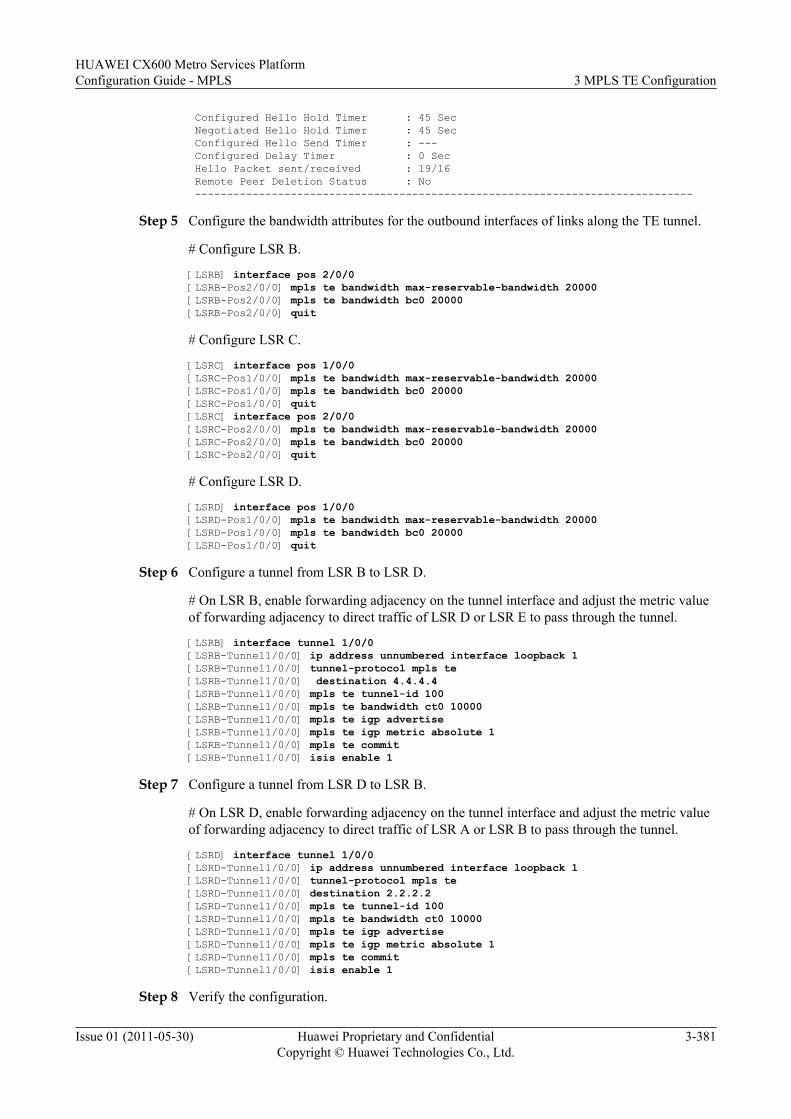
Configured Hello Hold Timer : 45 Sec Negotiated Hello Hold Timer : 45 Sec Configured Hello Send Timer : --- Configured Delay Timer : 0 Sec Hello Packet sent/received : 19/16 Remote Peer Deletion Status : No ------------------------------------------------------------------------------
Step 5 Configure the bandwidth attributes for the outbound interfaces of links along the TE tunnel.
# Configure LSR B.
[LSRB] interface pos 2/0/0[LSRB-Pos2/0/0] mpls te bandwidth max-reservable-bandwidth 20000[LSRB-Pos2/0/0] mpls te bandwidth bc0 20000[LSRB-Pos2/0/0] quit
# Configure LSR C.
[LSRC] interface pos 1/0/0[LSRC-Pos1/0/0] mpls te bandwidth max-reservable-bandwidth 20000[LSRC-Pos1/0/0] mpls te bandwidth bc0 20000[LSRC-Pos1/0/0] quit[LSRC] interface pos 2/0/0[LSRC-Pos2/0/0] mpls te bandwidth max-reservable-bandwidth 20000[LSRC-Pos2/0/0] mpls te bandwidth bc0 20000[LSRC-Pos2/0/0] quit
# Configure LSR D.
[LSRD] interface pos 1/0/0[LSRD-Pos1/0/0] mpls te bandwidth max-reservable-bandwidth 20000[LSRD-Pos1/0/0] mpls te bandwidth bc0 20000[LSRD-Pos1/0/0] quit
Step 6 Configure a tunnel from LSR B to LSR D.
# On LSR B, enable forwarding adjacency on the tunnel interface and adjust the metric valueof forwarding adjacency to direct traffic of LSR D or LSR E to pass through the tunnel.
[LSRB] interface tunnel 1/0/0[LSRB-Tunnel1/0/0] ip address unnumbered interface loopback 1[LSRB-Tunnel1/0/0] tunnel-protocol mpls te[LSRB-Tunnel1/0/0] destination 4.4.4.4[LSRB-Tunnel1/0/0] mpls te tunnel-id 100[LSRB-Tunnel1/0/0] mpls te bandwidth ct0 10000[LSRB-Tunnel1/0/0] mpls te igp advertise[LSRB-Tunnel1/0/0] mpls te igp metric absolute 1[LSRB-Tunnel1/0/0] mpls te commit[LSRB-Tunnel1/0/0] isis enable 1
Step 7 Configure a tunnel from LSR D to LSR B.
# On LSR D, enable forwarding adjacency on the tunnel interface and adjust the metric valueof forwarding adjacency to direct traffic of LSR A or LSR B to pass through the tunnel.
[LSRD] interface tunnel 1/0/0[LSRD-Tunnel1/0/0] ip address unnumbered interface loopback 1[LSRD-Tunnel1/0/0] tunnel-protocol mpls te[LSRD-Tunnel1/0/0] destination 2.2.2.2[LSRD-Tunnel1/0/0] mpls te tunnel-id 100[LSRD-Tunnel1/0/0] mpls te bandwidth ct0 10000[LSRD-Tunnel1/0/0] mpls te igp advertise[LSRD-Tunnel1/0/0] mpls te igp metric absolute 1[LSRD-Tunnel1/0/0] mpls te commit[LSRD-Tunnel1/0/0] isis enable 1
Step 8 Verify the configuration.
HUAWEI CX600 Metro Services PlatformConfiguration Guide - MPLS 3 MPLS TE Configuration
Issue 01 (2011-05-30) Huawei Proprietary and ConfidentialCopyright © Huawei Technologies Co., Ltd.
3-381
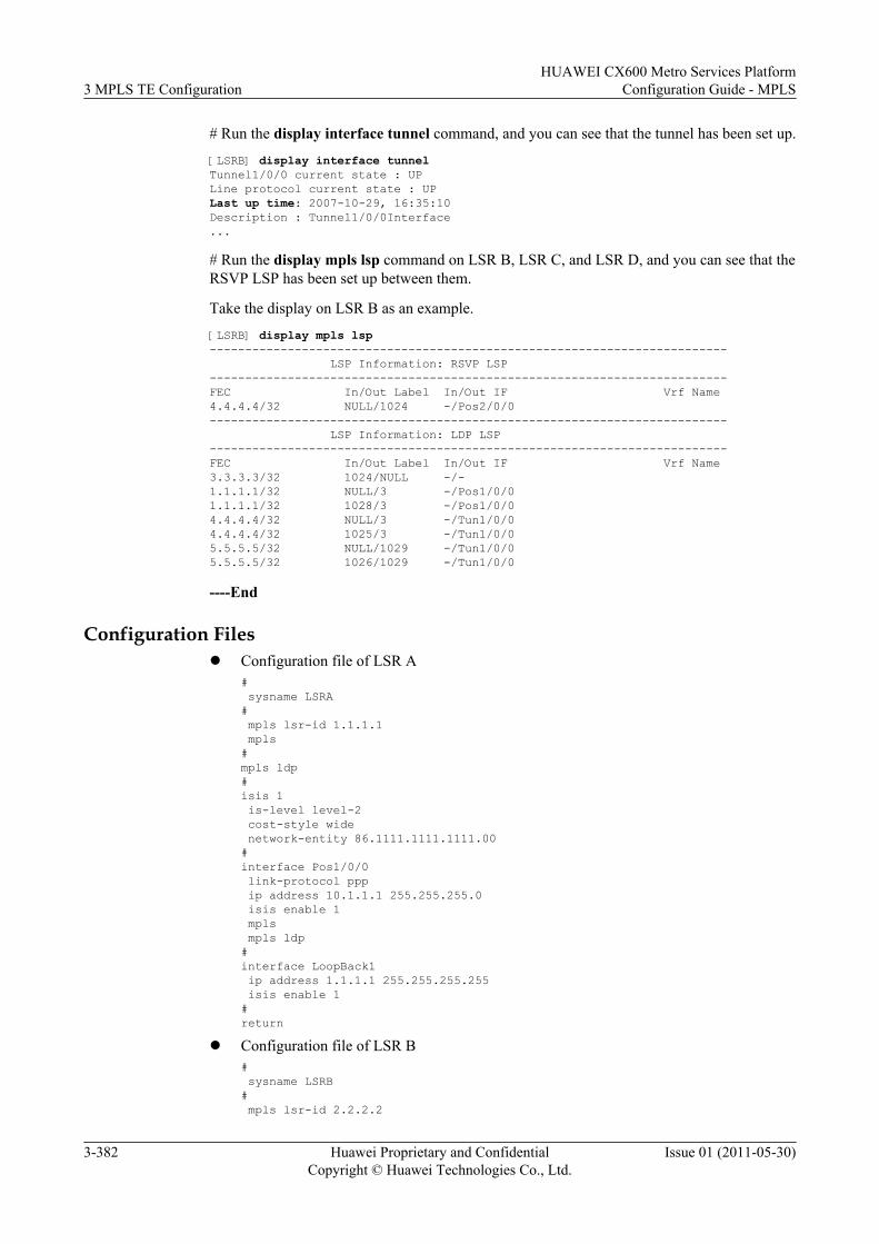
# Run the display interface tunnel command, and you can see that the tunnel has been set up.
[LSRB] display interface tunnelTunnel1/0/0 current state : UPLine protocol current state : UPLast up time: 2007-10-29, 16:35:10Description : Tunnel1/0/0Interface...
# Run the display mpls lsp command on LSR B, LSR C, and LSR D, and you can see that theRSVP LSP has been set up between them.
Take the display on LSR B as an example.
[LSRB] display mpls lsp------------------------------------------------------------------------- LSP Information: RSVP LSP-------------------------------------------------------------------------FEC In/Out Label In/Out IF Vrf Name4.4.4.4/32 NULL/1024 -/Pos2/0/0------------------------------------------------------------------------- LSP Information: LDP LSP-------------------------------------------------------------------------FEC In/Out Label In/Out IF Vrf Name3.3.3.3/32 1024/NULL -/-1.1.1.1/32 NULL/3 -/Pos1/0/01.1.1.1/32 1028/3 -/Pos1/0/0 4.4.4.4/32 NULL/3 -/Tun1/0/04.4.4.4/32 1025/3 -/Tun1/0/05.5.5.5/32 NULL/1029 -/Tun1/0/05.5.5.5/32 1026/1029 -/Tun1/0/0
----End
Configuration Filesl Configuration file of LSR A
# sysname LSRA# mpls lsr-id 1.1.1.1 mpls#mpls ldp#isis 1 is-level level-2 cost-style wide network-entity 86.1111.1111.1111.00#interface Pos1/0/0 link-protocol ppp ip address 10.1.1.1 255.255.255.0 isis enable 1 mpls mpls ldp#interface LoopBack1 ip address 1.1.1.1 255.255.255.255 isis enable 1#return
l Configuration file of LSR B# sysname LSRB# mpls lsr-id 2.2.2.2
3 MPLS TE ConfigurationHUAWEI CX600 Metro Services Platform
Configuration Guide - MPLS
3-382 Huawei Proprietary and ConfidentialCopyright © Huawei Technologies Co., Ltd.
Issue 01 (2011-05-30)
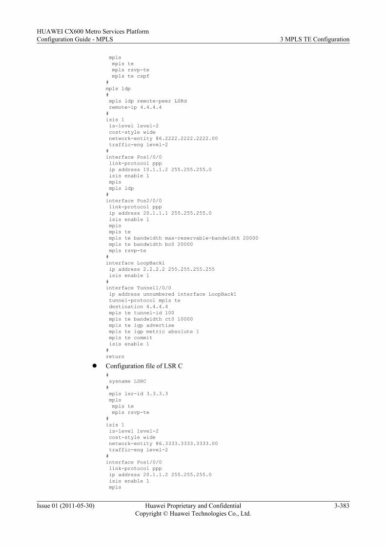
mpls mpls te mpls rsvp-te mpls te cspf#mpls ldp# mpls ldp remote-peer LSRd remote-ip 4.4.4.4#isis 1 is-level level-2 cost-style wide network-entity 86.2222.2222.2222.00 traffic-eng level-2#interface Pos1/0/0 link-protocol ppp ip address 10.1.1.2 255.255.255.0 isis enable 1 mpls mpls ldp#interface Pos2/0/0 link-protocol ppp ip address 20.1.1.1 255.255.255.0 isis enable 1 mpls mpls te mpls te bandwidth max-reservable-bandwidth 20000 mpls te bandwidth bc0 20000 mpls rsvp-te#interface LoopBack1 ip address 2.2.2.2 255.255.255.255 isis enable 1#interface Tunnel1/0/0 ip address unnumbered interface LoopBack1 tunnel-protocol mpls te destination 4.4.4.4 mpls te tunnel-id 100 mpls te bandwidth ct0 10000 mpls te igp advertise mpls te igp metric absolute 1 mpls te commit isis enable 1#return
l Configuration file of LSR C# sysname LSRC# mpls lsr-id 3.3.3.3 mpls mpls te mpls rsvp-te#isis 1 is-level level-2 cost-style wide network-entity 86.3333.3333.3333.00 traffic-eng level-2#interface Pos1/0/0 link-protocol ppp ip address 20.1.1.2 255.255.255.0 isis enable 1 mpls
HUAWEI CX600 Metro Services PlatformConfiguration Guide - MPLS 3 MPLS TE Configuration
Issue 01 (2011-05-30) Huawei Proprietary and ConfidentialCopyright © Huawei Technologies Co., Ltd.
3-383
mpls te mpls te bandwidth max-reservable-bandwidth 20000 mpls te bandwidth bc0 20000 mpls rsvp-te#interface Pos2/0/0 link-protocol ppp ip address 30.1.1.1 255.255.255.0 isis enable 1 mpls mpls te mpls te bandwidth max-reservable-bandwidth 20000 mpls te bandwidth bc0 20000 mpls rsvp-te#interface LoopBack1 ip address 3.3.3.3 255.255.255.255 isis enable 1#return
l Configuration file of LSR D# sysname LSRD# mpls lsr-id 4.4.4.4 mpls mpls te mpls rsvp-te mpls te cspf#mpls ldp# mpls ldp remote-peer LSRd remote-ip 2.2.2.2#isis 1 is-level level-2 cost-style wide network-entity 86.4444.4444.4444.00 traffic-eng level-2#interface Pos1/0/0 link-protocol ppp ip address 30.1.1.2 255.255.255.0 isis enable 1 mpls mpls te mpls te bandwidth max-reservable-bandwidth 20000 mpls te bandwidth bc0 20000 mpls rsvp-te#interface Pos2/0/0 link-protocol ppp ip address 40.1.1.1 255.255.255.0 isis enable 1 mpls mpls ldp#interface LoopBack1 ip address 4.4.4.4 255.255.255.255 isis enable 1#interface Tunnel1/0/0 ip address unnumbered interface LoopBack1 tunnel-protocol mpls te destination 2.2.2.2 mpls te tunnel-id 100 mpls te bandwidth ct0 10000 mpls te igp advertise
3 MPLS TE ConfigurationHUAWEI CX600 Metro Services Platform
Configuration Guide - MPLS
3-384 Huawei Proprietary and ConfidentialCopyright © Huawei Technologies Co., Ltd.
Issue 01 (2011-05-30)
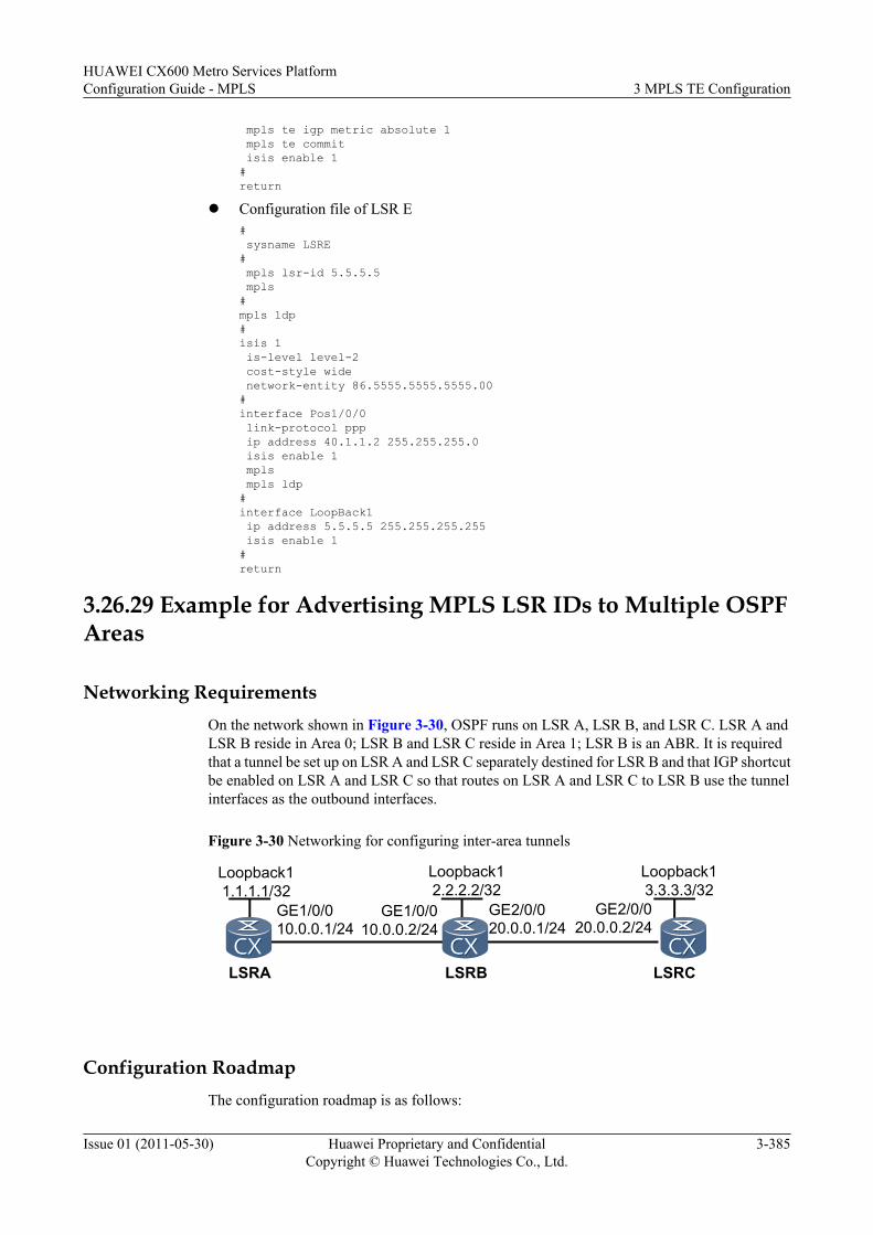
mpls te igp metric absolute 1 mpls te commit isis enable 1#return
l Configuration file of LSR E# sysname LSRE# mpls lsr-id 5.5.5.5 mpls#mpls ldp#isis 1 is-level level-2 cost-style wide network-entity 86.5555.5555.5555.00#interface Pos1/0/0 link-protocol ppp ip address 40.1.1.2 255.255.255.0 isis enable 1 mpls mpls ldp#interface LoopBack1 ip address 5.5.5.5 255.255.255.255 isis enable 1#return
3.26.29 Example for Advertising MPLS LSR IDs to Multiple OSPFAreas
Networking RequirementsOn the network shown in Figure 3-30, OSPF runs on LSR A, LSR B, and LSR C. LSR A andLSR B reside in Area 0; LSR B and LSR C reside in Area 1; LSR B is an ABR. It is requiredthat a tunnel be set up on LSR A and LSR C separately destined for LSR B and that IGP shortcutbe enabled on LSR A and LSR C so that routes on LSR A and LSR C to LSR B use the tunnelinterfaces as the outbound interfaces.
Figure 3-30 Networking for configuring inter-area tunnels
LSRB
GE1/0/010.0.0.1/24
GE1/0/010.0.0.2/24
LSRA LSRC
GE2/0/020.0.0.1/24
GE2/0/020.0.0.2/24
Loopback11.1.1.1/32
Loopback12.2.2.2/32
Loopback13.3.3.3/32
Configuration RoadmapThe configuration roadmap is as follows:
HUAWEI CX600 Metro Services PlatformConfiguration Guide - MPLS 3 MPLS TE Configuration
Issue 01 (2011-05-30) Huawei Proprietary and ConfidentialCopyright © Huawei Technologies Co., Ltd.
3-385
1. Configure an IP address for each interface on the LSRs and the loopback interface addressused as the LSR ID, and configure OSPF to advertise the network segments connected tothe interfaces on the LSRs and host routes of LSR IDs.
2. Configure the LSR ID of each LSR and enable MPLS, MPLS TE, and MPLS RSVP-TEon each LSR and interface.
3. Set up a tunnel destined to LSR B on LSR A and LSR C separately and enable IGP shortcuton LSR A and LSR C.
4. Run the advertise mpls-lsr-id command on LSR B so that the host route 2.2.2.2, an inter-area route, is advertised to both Area 0 and Area 1.
Data PreparationTo complete the configuration, you need the following data:
l OSPF process ID and area ID of each LSRl Interface number, IP address, destination address, and tunnel ID of each tunnel interface
on LSR A and LSR C
Procedure
Step 1 Configure an IP address for each interface on the LSRs and configure OSPF.
Configure an IP address and a mask for each interface and configure OSPF so that all LSRs cancommunicate with each other.
The configuration details are not provided here.
Step 2 Configure basic MPLS functions and enable MPLS TE and MPLS RSVP-TE.
# Configure LSR A.
[LSRA] mpls lsr-id 1.1.1.1[LSRA] mpls[LSRA-mpls] mpls te[LSRA-mpls] mpls rsvp-te[LSRA-mpls] quit[LSRA] interface gigabitethernet 1/0/0[LSRA-GigabitEthernet1/0/0] ospf network-type p2p[LSRA-GigabitEthernet1/0/0] mpls[LSRA-GigabitEthernet1/0/0] mpls te[LSRA-GigabitEthernet1/0/0] mpls rsvp-te[LSRA-GigabitEthernet1/0/0] quit
The configuration performed on LSR B and LSR C is similar to that on LSR A, and thus are notprovided here.
Step 3 Configure an MPLS TE tunnel and IGP shortcut.
# Set up an MPLS TE tunnel from LSR A to LSR B and configure IGP shortcut. The OSPF costof the tunnel is smaller than that of the physical link.
[LSRA] interface tunnel 1/0/0[LSRA-Tunnel1/0/0] ip address unnumbered interface loopback 1[LSRA-Tunnel1/0/0] tunnel-protocol mpls te[LSRA-Tunnel1/0/0] destination 2.2.2.2[LSRA-Tunnel1/0/0] mpls te tunnel-id 100[LSRA-Tunnel1/0/0] mpls te igp shortcut ospf[LSRA-Tunnel1/0/0] mpls te igp metric absolute 1[LSRA-Tunnel1/0/0] mpls te commit[LSRA-Tunnel1/0/0] quit
3 MPLS TE ConfigurationHUAWEI CX600 Metro Services Platform
Configuration Guide - MPLS
3-386 Huawei Proprietary and ConfidentialCopyright © Huawei Technologies Co., Ltd.
Issue 01 (2011-05-30)
# Set up an MPLS TE tunnel from LSR C to LSR B and configure IGP shortcut. The OSPF costof the tunnel is smaller than that of the physical link.[LSRC] interface tunnel 2/0/0[LSRC-Tunnel2/0/0] ip address unnumbered interface loopback 1[LSRC-Tunnel2/0/0] tunnel-protocol mpls te[LSRC-Tunnel2/0/0] destination 2.2.2.2[LSRC-Tunnel2/0/0] mpls te tunnel-id 200[LSRC-Tunnel2/0/0] mpls te igp shortcut ospf[LSRC-Tunnel2/0/0] mpls te igp metric absolute 1[LSRC-Tunnel2/0/0] mpls te commit[LSRC-Tunnel2/0/0] quit
After the configurations are complete, run the display interface tunnel command on LSR A.You can see that the tunnel interface is Up.
# Run the display mpls te tunnel command on LSR A and LSR C. You can view informationabout each MPLS TE tunnel.<LSRA> display mpls te tunnelLSP-Id Destination In/Out-If1.1.1.1:100:1 2.2.2.2 -/GE1/0/0
<LSRC> display mpls te tunnelLSP-Id Destination In/Out-If3.3.3.3:200:1 2.2.2.2 -/GE2/0/0
Step 4 Configure the ABR so that LSR B can advertise MPLS LSR IDs to multiple OSPF areas.[LSRB] ospf 1[LSRB-ospf-1] advertise mpls-lsr-id
Step 5 Verify the configuration.
# Run the display ospf peer brief command on LSR B. You can see that each Area 0 and Area1 has a neighbor in the Full state.[LSRB] display ospf peer brief
OSPF Process 1 with Router ID 2.2.2.2 Peer Statistic Informations------------------------------------------------------------------------Area Id Interface Neighbor id State0.0.0.0 GigabitEthernet1/0/0 1.1.1.1 Full0.0.0.1 GigabitEthernet2/0/0 3.3.3.3 Full------------------------------------------------------------------------
# Run the display ip routing-table 2.2.2.2 command on LSR A. You can see that in the routingtable, the outbound interface of the route to 2.2.2.2 is a tunnel interface.<LSRA> display ip routing-table 2.2.2.2Route Flags: R - relay, D - download to fib------------------------------------------------------------------------------Routing Table : PublicSummary Count : 1Destination/Mask Proto Pre Cost Flags NextHop Interface
2.2.2.2/32 OSPF 10 1 D 1.1.1.1 Tunnel1/0/0
<LSRC> display ip routing-table 2.2.2.2Route Flags: R - relay, D - download to fib------------------------------------------------------------------------------Routing Table : PublicSummary Count : 1Destination/Mask Proto Pre Cost Flags NextHop Interface
2.2.2.2/32 OSPF 10 1 D 3.3.3.3 Tunnel2/0/0
----End
HUAWEI CX600 Metro Services PlatformConfiguration Guide - MPLS 3 MPLS TE Configuration
Issue 01 (2011-05-30) Huawei Proprietary and ConfidentialCopyright © Huawei Technologies Co., Ltd.
3-387
Configuration Filesl Configuration file of LSR A
# sysname LSRA# mpls lsr-id 1.1.1.1 mpls mpls te mpls rsvp-te#interface GigabitEthernet1/0/0 undo shutdown ip address 10.0.0.1 255.255.255.0 ospf cost 10 mpls mpls te mpls rsvp-te#interface LoopBack1 ip address 1.1.1.1 255.255.255.255#interface Tunnel1/0/0 ip address unnumbered interface LoopBack1 tunnel-protocol mpls te destination 2.2.2.2 mpls te tunnel-id 100 mpls te igp shortcut ospf mpls te igp metric absolute 1 mpls te commit#ospf 1 router-id 1.1.1.1 opaque-capability enable enable traffic-adjustment area 0.0.0.0 network 10.0.0.0 0.0.0.255 network 1.1.1.1 0.0.0.0 mpls-te enable#return
l Configuration file of LSR B# sysname LSRB# mpls lsr-id 2.2.2.2 mpls mpls te mpls rsvp-te#interface GigabitEthernet1/0/0 undo shutdown ip address 10.0.0.2 255.255.255.0 mpls mpls te mpls rsvp-te#interface GigabitEthernet2/0/0 undo shutdown ip address 20.0.0.1 255.255.255.0 mpls mpls te mpls rsvp-te#interface LoopBack0 ip address 2.2.2.2 255.255.255.255#ospf 1 router-id 2.2.2.2 opaque-capability enable
3 MPLS TE ConfigurationHUAWEI CX600 Metro Services Platform
Configuration Guide - MPLS
3-388 Huawei Proprietary and ConfidentialCopyright © Huawei Technologies Co., Ltd.
Issue 01 (2011-05-30)
enable traffic-adjustment advertise mpls-lsr-id area 0.0.0.0 network 10.0.0.0 0.0.0.255 mpls-te enable area 0.0.0.1 network 20.0.0.0 0.0.0.255 mpls-te enable#return
l Configuration file of LSR C# sysname LSRC# mpls lsr-id 3.3.3.3 mpls mpls te mpls rsvp-te#interface GigabitEthernet2/0/0 undo shutdown ip address 20.0.0.2 255.255.255.0 ospf cost 10 mpls mpls te mpls rsvp-te#interface NULL0#interface LoopBack0 ip address 3.3.3.3 255.255.255.255#interface Tunnel2/0/0 ip address unnumbered interface LoopBack0 tunnel-protocol mpls te destination 2.2.2.2 mpls te tunnel-id 200 mpls te igp shortcut ospf mpls te igp metric absolute 1 mpls te commit#ospf 1 router-id 3.3.3.3 opaque-capability enable enable traffic-adjustment area 0.0.0.1 network 20.0.0.0 0.0.0.255 network 3.3.3.3 0.0.0.0 mpls-te enable#return
3.26.30 Example for Configuring an Inter-Area TunnelThis section provides an example for configuring a TE tunnel between IS-IS areas.
Networking Requirements
On the network shown in Figure 3-31,
l IS-IS is run on LSR A, LSR B, LSR C, LSR D, and LSR E.
– LSR A and LSR E are Level-1 devices.
– LSR B and LSR D are Level-1-2 devices.
– LSR C is Level-2 devices.
HUAWEI CX600 Metro Services PlatformConfiguration Guide - MPLS 3 MPLS TE Configuration
Issue 01 (2011-05-30) Huawei Proprietary and ConfidentialCopyright © Huawei Technologies Co., Ltd.
3-389
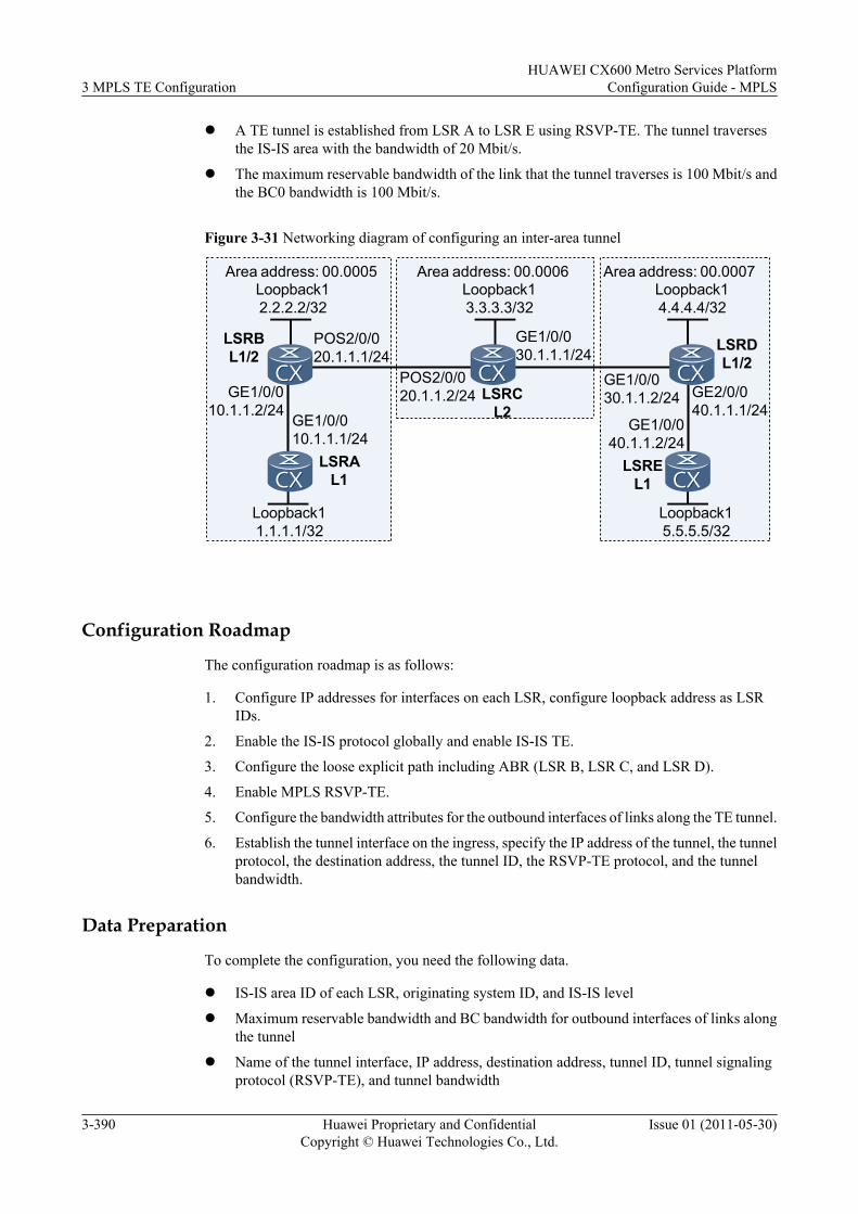
l A TE tunnel is established from LSR A to LSR E using RSVP-TE. The tunnel traversesthe IS-IS area with the bandwidth of 20 Mbit/s.
l The maximum reservable bandwidth of the link that the tunnel traverses is 100 Mbit/s andthe BC0 bandwidth is 100 Mbit/s.
Figure 3-31 Networking diagram of configuring an inter-area tunnel
Loopback11.1.1.1/32
Loopback12.2.2.2/32
Loopback13.3.3.3/32
Loopback14.4.4.4/32
LSRAL1
LSRBL1/2
LSRCL2
LSRDL1/2
GE1/0/010.1.1.1/24
GE1/0/010.1.1.2/24
POS2/0/020.1.1.1/24
POS2/0/020.1.1.2/24
GE1/0/030.1.1.1/24
GE1/0/030.1.1.2/24
LSREL1
Loopback15.5.5.5/32
GE1/0/040.1.1.2/24
GE2/0/040.1.1.1/24
Area address: 00.0005 Area address: 00.0006 Area address: 00.0007
Configuration Roadmap
The configuration roadmap is as follows:
1. Configure IP addresses for interfaces on each LSR, configure loopback address as LSRIDs.
2. Enable the IS-IS protocol globally and enable IS-IS TE.
3. Configure the loose explicit path including ABR (LSR B, LSR C, and LSR D).
4. Enable MPLS RSVP-TE.
5. Configure the bandwidth attributes for the outbound interfaces of links along the TE tunnel.
6. Establish the tunnel interface on the ingress, specify the IP address of the tunnel, the tunnelprotocol, the destination address, the tunnel ID, the RSVP-TE protocol, and the tunnelbandwidth.
Data Preparation
To complete the configuration, you need the following data.
l IS-IS area ID of each LSR, originating system ID, and IS-IS level
l Maximum reservable bandwidth and BC bandwidth for outbound interfaces of links alongthe tunnel
l Name of the tunnel interface, IP address, destination address, tunnel ID, tunnel signalingprotocol (RSVP-TE), and tunnel bandwidth
3 MPLS TE ConfigurationHUAWEI CX600 Metro Services Platform
Configuration Guide - MPLS
3-390 Huawei Proprietary and ConfidentialCopyright © Huawei Technologies Co., Ltd.
Issue 01 (2011-05-30)
Procedure
Step 1 Configure an IP address for each interface.
Configure the IP address and mask for each interface, including the loopback interface as shownin Figure 3-31.
The configuration details are not provided here.
Step 2 Configure the IS-IS protocol to advertise routes.
# Configure LSR A.
[LSRA] isis 1[LSRA-isis-1] network-entity 00.0005.0000.0000.0001.00[LSRA-isis-1] is-level level-1[LSRA-isis-1] quit[LSRA] interface gigabitethernet 1/0/0[LSRA-GigabitEthernet1/0/0] isis enable 1[LSRA-GigabitEthernet1/0/0] quit[LSRA] interface loopback 1[LSRA-LoopBack1] isis enable 1[LSRA-LoopBack1] quit
# Configure LSR B.
[LSRB] isis 1[LSRB-isis-1] network-entity 00.0005.0000.0000.0002.00[LSRB-isis-1] is-level level-1-2[LSRB-isis-1] import-route isis level-2 into level-1[LSRB-isis-1] quit[LSRB] interface gigabitethernet 1/0/0[LSRB-GigabitEthernet1/0/0] isis enable 1[LSRB-GigabitEthernet1/0/0] quit[LSRB] interface pos 2/0/0[LSRB-Pos2/0/0] isis enable 1[LSRB-Pos2/0/0] quit[LSRB] interface loopback 1[LSRB-LoopBack1] isis enable 1[LSRB-LoopBack1] quit
# Configure LSR C.
[LSRC] isis 1[LSRC-isis-1] network-entity 00.0006.0000.0000.0003.00[LSRC-isis-1] is-level level-2[LSRC-isis-1] quit[LSRC] interface gigabitethernet 1/0/0[LSRC-GigabitEthernet1/0/0] isis enable 1[LSRC-GigabitEthernet1/0/0] quit[LSRC] interface pos 2/0/0[LSRC-Pos2/0/0] isis enable 1[LSRC-Pos2/0/0] quit[LSRC] interface loopback 1[LSRC-LoopBack1] isis enable 1[LSRC-LoopBack1] quit
# Configure LSR D.
[LSRD] isis 1[LSRD-isis-1] network-entity 00.0007.0000.0000.0004.00[LSRD-isis-1] is-level level-1-2[LSRD-isis-1] import-route isis level-2 into level-1[LSRD-isis-1] quit[LSRD] interface gigabitethernet 1/0/0[LSRD-GigabitEthernet1/0/0] isis enable 1[LSRD-GigabitEthernet1/0/0] quit[LSRD] interface gigabitethernet 2/0/0
HUAWEI CX600 Metro Services PlatformConfiguration Guide - MPLS 3 MPLS TE Configuration
Issue 01 (2011-05-30) Huawei Proprietary and ConfidentialCopyright © Huawei Technologies Co., Ltd.
3-391
[LSRD-GigabitEthernet2/0/0] isis enable 1[LSRD-GigabitEthernet2/0/0] quit[LSRD] interface loopback 1[LSRD-LoopBack1] isis enable 1[LSRD-LoopBack1] quit
# Configure LSR E.
[LSRE] isis 1[LSRE-isis-1] network-entity 00.0007.0000.0000.0005.00[LSRE-isis-1] is-level level-1[LSRE-isis-1] quit[LSRE] interface gigabitethernet 1/0/0[LSRE-GigabitEthernet1/0/0] isis enable 1[LSRE-GigabitEthernet1/0/0] quit[LSRE] interface loopback 1[LSRE-LoopBack1] isis enable 1[LSRE-LoopBack1] quit
Step 3 Configure basic MPLS functions, enable MPLS TE, RSVP-TE, and enable CSPF on the ingressof the tunnel.
# Configure LSR A.
[LSRA] mpls lsr-id 1.1.1.1[LSRA] mpls[LSRA-mpls] mpls te[LSRA-mpls] mpls rsvp-te[LSRA-mpls] mpls te cspf[LSRA-mpls] quit[LSRA] interface gigabitethernet 1/0/0[LSRA-GigabitEthernet1/0/0] mpls[LSRA-GigabitEthernet1/0/0] mpls te[LSRA-GigabitEthernet1/0/0] mpls rsvp-te[LSRA-GigabitEthernet1/0/0] quit
# Configure LSR B.
[LSRB] mpls lsr-id 2.2.2.2[LSRB] mpls[LSRB-mpls] mpls te[LSRB-mpls] mpls rsvp-te[LSRB-mpls] quit[LSRB] interface gigabitethernet 1/0/0[LSRB-GigabitEthernet1/0/0] mpls[LSRB-GigabitEthernet1/0/0] mpls te[LSRB-GigabitEthernet1/0/0] mpls rsvp-te[LSRB-GigabitEthernet1/0/0] quit[LSRB] interface pos 2/0/0[LSRB-Pos2/0/0] mpls[LSRB-Pos2/0/0] mpls te[LSRB-Pos2/0/0] mpls rsvp-te[LSRB-Pos2/0/0] quit
# Configure LSR C.
[LSRC] mpls lsr-id 3.3.3.3[LSRC] mpls[LSRC-mpls] mpls te[LSRC-mpls] mpls rsvp-te[LSRC-mpls] quit[LSRC] interface gigabitethernet 1/0/0[LSRC-GigabitEthernet1/0/0] mpls[LSRC-GigabitEthernet1/0/0] mpls te[LSRC-GigabitEthernet1/0/0] mpls rsvp-te[LSRC-GigabitEthernet1/0/0] quit[LSRC] interface pos 2/0/0[LSRC-Pos2/0/0] mpls[LSRC-Pos2/0/0] mpls te[LSRC-Pos2/0/0] mpls rsvp-te
3 MPLS TE ConfigurationHUAWEI CX600 Metro Services Platform
Configuration Guide - MPLS
3-392 Huawei Proprietary and ConfidentialCopyright © Huawei Technologies Co., Ltd.
Issue 01 (2011-05-30)
[LSRC-Pos2/0/0] quit
# Configure LSR D.
[LSRD] mpls lsr-id 4.4.4.4[LSRD] mpls[LSRD-mpls] mpls te[LSRD-mpls] mpls rsvp-te[LSRD-mpls] quit[LSRD] interface gigabitethernet 1/0/0[LSRD-GigabitEthernet1/0/0] mpls[LSRD-GigabitEthernet1/0/0] mpls te[LSRD-GigabitEthernet1/0/0] mpls rsvp-te[LSRD-GigabitEthernet1/0/0] quit[LSRD] interface gigabitethernet 2/0/0[LSRD-GigabitEthernet2/0/0] mpls[LSRD-GigabitEthernet2/0/0] mpls te[LSRD-GigabitEthernet2/0/0] mpls rsvp-te[LSRD-GigabitEthernet2/0/0] quit
# Configure LSR E.
[LSRE] mpls lsr-id 5.5.5.5[LSRE] mpls[LSRE-mpls] mpls te[LSRE-mpls] mpls rsvp-te[LSRE-mpls] quit[LSRE] interface gigabitethernet 1/0/0[LSRE-GigabitEthernet1/0/0] mpls[LSRE-GigabitEthernet1/0/0] mpls te[LSRE-GigabitEthernet1/0/0] mpls rsvp-te[LSRE-GigabitEthernet1/0/0] quit
Step 4 Configure IS-IS TE.
# Configure LSR A.
[LSRA] isis 1[LSRA-isis-1] cost-style wide[LSRA-isis-1] traffic-eng level-1[LSRA-isis-1] quit
# Configure LSR B.
[LSRB] isis 1[LSRB-isis-1] cost-style wide[LSRB-isis-1] traffic-eng level-1-2[LSRB-isis-1] quit
# Configure LSR C.
[LSRC] isis 1[LSRC-isis-1] cost-style wide[LSRC-isis-1] traffic-eng level-2[LSRC-isis-1] quit
# Configure LSR D.
[LSRD] isis 1[LSRD-isis-1] cost-style wide[LSRD-isis-1] traffic-eng level-1-2[LSRD-isis-1] quit
# Configure LSR E.
[LSRE] isis 1[LSRE-isis-1] cost-style wide[LSRE-isis-1] traffic-eng level-1[LSRE-isis-1] quit
HUAWEI CX600 Metro Services PlatformConfiguration Guide - MPLS 3 MPLS TE Configuration
Issue 01 (2011-05-30) Huawei Proprietary and ConfidentialCopyright © Huawei Technologies Co., Ltd.
3-393
Step 5 Configure the loose explicit path.[LSRA] explicit-path atoe[LSRA-explicit-path-atoe] next hop 10.1.1.2 include loose[LSRA-explicit-path-atoe] next hop 20.1.1.2 include loose[LSRA-explicit-path-atoe] next hop 30.1.1.2 include loose[LSRA-explicit-path-atoe] next hop 40.1.1.2 include loose
Step 6 Configure MPLS TE attributes for the link.
# Configure the maximum reservable bandwidth and the BC0 bandwidth for the link on LSR A.
[LSRA] interface gigabitethernet 1/0/0[LSRA-GigabitEthernet1/0/0] mpls te bandwidth max-reservable-bandwidth 100000[LSRA-GigabitEthernet1/0/0] mpls te bandwidth bc0 100000[LSRA-GigabitEthernet1/0/0] quit
# Configure the maximum bandwidth and the maximum reservable bandwidth for the link onLSR B.
[LSRB] interface pos 2/0/0[LSRB-Pos2/0/0] mpls te bandwidth max-reservable-bandwidth 100000[LSRB-Pos2/0/0] mpls te bandwidth bc0 100000[LSRB-Pos2/0/0] quit
# Configure the maximum bandwidth and the maximum reservable bandwidth for the link onLSR C.
[LSRC] interface gigabitethernet 1/0/0[LSRC-GigabitEthernet1/0/0] mpls te bandwidth max-reservable-bandwidth 100000[LSRC-GigabitEthernet1/0/0] mpls te bandwidth bc0 100000[LSRC-GigabitEthernet1/0/0] quit
# Configure the maximum bandwidth and the maximum reservable bandwidth for the link onLSR D.
[LSRD] interface gigabitethernet 2/0/0[LSRD-GigabitEthernet2/0/0] mpls te bandwidth max-reservable-bandwidth 100000[LSRD-GigabitEthernet2/0/0] mpls te bandwidth bc0 100000[LSRD-GigabitEthernet2/0/0] quit
Step 7 Configure an MPLS TE tunnel.
# Configure an MPLS TE tunnel on LSR A.
[LSRA] interface tunnel 1/0/0[LSRA-Tunnel1/0/0] ip address unnumbered interface loopback 1[LSRA-Tunnel1/0/0] tunnel-protocol mpls te[LSRA-Tunnel1/0/0] destination 5.5.5.5[LSRA-Tunnel1/0/0] mpls te tunnel-id 100[LSRA-Tunnel1/0/0] mpls te signal-protocol rsvp-te[LSRA-Tunnel1/0/0] mpls te bandwidth ct0 20000[LSRA-Tunnel1/0/0] mpls te path explicit-path atoe[LSRA-Tunnel1/0/0] mpls te commit[LSRA-Tunnel1/0/0] quit
Step 8 Verify the configuration.
After the configuration, run the display interface tunnel command on LSR A, and you can seethat the status of the tunnel interface is Up.
[LSRA] display interface TunnelTunnel1/0/0 current state : UPLine protocol current state : UPLast up time: 2009-01-16, 10:36:20Description : Tunnel1/0/0 Interface, Route Port...
3 MPLS TE ConfigurationHUAWEI CX600 Metro Services Platform
Configuration Guide - MPLS
3-394 Huawei Proprietary and ConfidentialCopyright © Huawei Technologies Co., Ltd.
Issue 01 (2011-05-30)
# Run the display mpls te tunnel verbose command on LSR A to display information aboutthe tunnel.
[LSRA] display mpls te tunnel verbose No : 1 Tunnel-Name : Tunnel1/0/0 TunnelIndex : 0 LSP Index : 2048 Session ID : 100 LSP ID : 1 Lsr Role : Ingress Lsp Type : Primary Ingress LSR ID : 1.1.1.1 Egress LSR ID : 5.5.5.5 In-Interface : - Out-Interface : GE1/0/0 Sign-Protocol : RSVP TE Resv Style : SE IncludeAnyAff : 0x0 ExcludeAnyAff : 0x0 IncludeAllAff : 0x0 LspConstraint : - ER-Hop Table Index : 0 AR-Hop Table Index: - C-Hop Table Index : 0 PrevTunnelIndexInSession: - NextTunnelIndexInSession: - PSB Handle : 1024 Created Time : 2010/09/09 16:40:44 UTC-08:00 -------------------------------- DS-TE Information -------------------------------- Bandwidth Reserved Flag : Reserved CT0 Bandwidth(Kbit/sec) : 20000 CT1 Bandwidth(Kbit/sec): 0 CT2 Bandwidth(Kbit/sec) : 0 CT3 Bandwidth(Kbit/sec): 0 CT4 Bandwidth(Kbit/sec) : 0 CT5 Bandwidth(Kbit/sec): 0 CT6 Bandwidth(Kbit/sec) : 0 CT7 Bandwidth(Kbit/sec): 0 Setup-Priority : 7 Hold-Priority : 7 -------------------------------- FRR Information -------------------------------- Primary LSP Info TE Attribute Flag : 0x3 Protected Flag : 0x0 Bypass In Use : Not Exists Bypass Tunnel Id : - BypassTunnel : - Bypass Lsp ID : - FrrNextHop : - ReferAutoBypassHandle : - FrrPrevTunnelTableIndex : - FrrNextTunnelTableIndex: - Bypass Attribute(Not configured) Setup Priority : - Hold Priority : - HopLimit : - Bandwidth : - IncludeAnyGroup : - ExcludeAnyGroup : - IncludeAllGroup : - Bypass Unbound Bandwidth Info(Kbit/sec) CT0 Unbound Bandwidth : - CT1 Unbound Bandwidth: - CT2 Unbound Bandwidth : - CT3 Unbound Bandwidth: - CT4 Unbound Bandwidth : - CT5 Unbound Bandwidth: - CT6 Unbound Bandwidth : - CT7 Unbound Bandwidth: - -------------------------------- BFD Information -------------------------------- NextSessionTunnelIndex : - PrevSessionTunnelIndex: - NextLspId : - PrevLspId : -
----End
Configuration Filesl Configuration file of LSR A
# sysname LSRA# mpls lsr-id 1.1.1.1 mpls
HUAWEI CX600 Metro Services PlatformConfiguration Guide - MPLS 3 MPLS TE Configuration
Issue 01 (2011-05-30) Huawei Proprietary and ConfidentialCopyright © Huawei Technologies Co., Ltd.
3-395
mpls te mpls rsvp-te mpls te cspf# explicit-path atoe next hop 10.1.1.2 include loose next hop 20.1.1.2 include loose next hop 30.1.1.2 include loose next hop 40.1.1.2 include loose# isis 1 is-level level-1 cost-style wide network-entity 00.0005.0000.0000.0001.00 traffic-eng level-1#interface GigabitEthernet1/0/0 ip address 10.1.1.1 255.255.255.0 isis enable 1 mpls mpls te mpls te bandwidth max-reservable-bandwidth 100000 mpls te bandwidth bc0 100000 mpls rsvp-te#interface LoopBack1 ip address 1.1.1.1 255.255.255.255 isis enable 1#interface Tunnel1/0/0 ip address unnumbered interface LoopBack1 tunnel-protocol mpls te destination 5.5.5.5 mpls te tunnel-id 100 mpls te bandwidth ct0 20000mpls te path explicit-path atoe mpls te commit#return
l Configuration file of LSR B# sysname LSRB# mpls lsr-id 2.2.2.2 mpls mpls te mpls rsvp-te#isis 1 is-level level-1-2 cost-style wideimport-route isis level-2 into level-1 network-entity 00.0005.0000.0000.0002.00 traffic-eng level-1-2#interface GigabitEthernet1/0/0 ip address 10.1.1.2 255.255.255.0 isis enable 1 mpls mpls te mpls rsvp-te#interface Pos2/0/0 link-protocol ppp clock master ip address 20.1.1.1 255.255.255.0 isis enable 1 mpls mpls te
3 MPLS TE ConfigurationHUAWEI CX600 Metro Services Platform
Configuration Guide - MPLS
3-396 Huawei Proprietary and ConfidentialCopyright © Huawei Technologies Co., Ltd.
Issue 01 (2011-05-30)
mpls te bandwidth max-reservable-bandwidth 100000 mpls te bandwidth bc0 100000 mpls rsvp-te#interface LoopBack1 ip address 2.2.2.2 255.255.255.255 isis enable 1#return
l Configuration file of LSR C# sysname LSRC# mpls lsr-id 3.3.3.3 mpls mpls te mpls rsvp-te#isis 1 is-level level-2 cost-style wide network-entity 00.0006.0000.0000.0003.00 traffic-eng level-2#interface GigabitEthernet1/0/0 ip address 30.1.1.1 255.255.255.0 isis enable 1 mpls mpls te mpls te bandwidth max-reservable-bandwidth 100000 mpls te bandwidth bc0 100000 mpls rsvp-te#interface Pos2/0/0 link-protocol ppp ip address 20.1.1.2 255.255.255.0 isis enable 1 mpls mpls te mpls rsvp-te#interface LoopBack1 ip address 3.3.3.3 255.255.255.255 isis enable 1#return
l Configuration file of LSR D# sysname LSRD# mpls lsr-id 4.4.4.4 mpls mpls te mpls rsvp-te#isis 1 is-level level-1-2 cost-style wide network-entity 00.0007.0000.0000.0004.00import-route isis level-2 into level-1 traffic-eng level-1-2#interface GigabitEthernet1/0/0 ip address 30.1.1.2 255.255.255.0 isis enable 1 mpls mpls te mpls rsvp-te
HUAWEI CX600 Metro Services PlatformConfiguration Guide - MPLS 3 MPLS TE Configuration
Issue 01 (2011-05-30) Huawei Proprietary and ConfidentialCopyright © Huawei Technologies Co., Ltd.
3-397
#interface GigabitEthernet2/0/0 ip address 40.1.1.1 255.255.255.0 isis enable 1 mpls mpls te mpls te bandwidth max-reservable-bandwidth 100000 mpls te bandwidth bc0 100000 mpls rsvp-te#interface LoopBack1 ip address 4.4.4.4 255.255.255.255 isis enable 1#return
l Configuration file of LSR E# sysname LSRE# mpls lsr-id 5.5.5.5 mpls mpls te mpls rsvp-te#isis 1 is-level level-1 cost-style wide network-entity 00.0007.0000.0000.0005.00 traffic-eng level-1#interface GigabitEthernet1/0/0 ip address 40.1.1.2 255.255.255.0 isis enable 1 mpls mpls te mpls rsvp-te#interface LoopBack1 ip address 5.5.5.5 255.255.255.255 isis enable 1#return
3 MPLS TE ConfigurationHUAWEI CX600 Metro Services Platform
Configuration Guide - MPLS
3-398 Huawei Proprietary and ConfidentialCopyright © Huawei Technologies Co., Ltd.
Issue 01 (2011-05-30)
4 MPLS Common Configuration
About This Chapter
MPLS common configurations include the MPLS TTL handling mode, Layer 3 MPLS loadbalancing, PBR to the LSP on the public network, and MPLS optimization.
4.1 Introduction to MPLS Common ConfigurationMPLS supports multiple labels and the MPLS forwarding plane is connection-oriented, whichenables MPLS to be of well expansibility. With these features, MPLS can provide variousservices based on the fundamental MPLS and IP-integrated network architecture.
4.2 Configuring the Mode in Which MPLS Handles the TTLYou can configure an MPLS TTL handling mode only after enabling MPLS or configuring theMPLS VPN.
4.3 Configuring the Load Balancing of MPLS Layer 3 ForwardingYou can configure the MPLS load balancing function in per-flow forwarding mode or in per-packet load forwarding mode.
4.4 Optimizing MPLSTo optimize MPLS, you can adjust parameters of the PHP function, MPLS MTU on an interface,and Layer 3 MPLS load balancing function.
4.5 Maintaining MPLS Common ConfigurationThe operations of the MPLS common configurations include deleting MPLS statistics, detectingconnectivity and reachability of an LSP, and maintaining the PBR to an LSP.
HUAWEI CX600 Metro Services PlatformConfiguration Guide - MPLS 4 MPLS Common Configuration
Issue 01 (2011-05-30) Huawei Proprietary and ConfidentialCopyright © Huawei Technologies Co., Ltd.
4-1
4.1 Introduction to MPLS Common ConfigurationMPLS supports multiple labels and the MPLS forwarding plane is connection-oriented, whichenables MPLS to be of well expansibility. With these features, MPLS can provide variousservices based on the fundamental MPLS and IP-integrated network architecture.
4.1.1 Overview of MPLS Common FeaturesMPLS speeds up the forwarding of networks and can provide various new services.
4.1.2 MPLS Common Features Supported by the CX600The system supports the MPLS common features, including the MPLS TTL handling mode,PBR to the LSP, and MPLS ping and traceroute.
4.1.1 Overview of MPLS Common FeaturesMPLS speeds up the forwarding of networks and can provide various new services.
Originally, MPLS is set forth for improving the forwarding rate of the device, but this meanslittle now with the improvement of hardware technology. After all, MPLS is connection-orientedwith well expansibility and supports multiple-layer label. With these features, MPLS can providevarious services based on fundamental MPLS and IP-integrated network architecture. Thus,MPLS gradually becomes a basic technology applicable to large-scale networks.
MPLS VPN is highly evaluated by the IP network carrier in providing value-added services.With MPLS VPN technology, the current IP network is divided into logically-isolated networks.This technology is applicable to interconnection among companies and various new services.For example, despite lacking of IP network addresses, a VPN can be established especially forIP telephone services to provide QoS and new services.
4.1.2 MPLS Common Features Supported by the CX600The system supports the MPLS common features, including the MPLS TTL handling mode,PBR to the LSP, and MPLS ping and traceroute.
Processing Modes of MPLS TTL
The MPLS label contains an 8-bit TTL field. The meaning of the TTL field is similar to that ofthe TTL field in an IP header. The TTL can be used to prevent routing loops and to implementthe traceroute function.
In the CX600, you can set different TTL processing modes for VPN packets and public networkpackets. This implements that the Traceroute operations have different results.
MPLS Ping/Traceroute
The MPLS Ping and Traceroute help to detect LSP faults and locate the faulty nodes.
Similar to IP Ping and Traceroute, MPLS Ping and Traceroute use the echo request and echoreply messages to detect the availability of the LSP. Echo request and echo reply messages aretransferred in User Datagram Protocol (UDP) datagram with the port number being 3503.
4 MPLS Common ConfigurationHUAWEI CX600 Metro Services Platform
Configuration Guide - MPLS
4-2 Huawei Proprietary and ConfidentialCopyright © Huawei Technologies Co., Ltd.
Issue 01 (2011-05-30)
4.2 Configuring the Mode in Which MPLS Handles the TTLYou can configure an MPLS TTL handling mode only after enabling MPLS or configuring theMPLS VPN.
4.2.1 Establishing the Configuration TaskBefore configuring an MPLS TTL handling mode, familiarize yourself with the applicableenvironment, complete the pre-configuration tasks, and obtain the required data. This can helpyou complete the configuration task quickly and accurately.
4.2.2 Configuring MPLS Uniform ModeMPLS handles TTLs in Uniform mode.
4.2.3 Configuring MPLS Pipe ModeMPLS handles TTLs in Pipe mode.
4.2.4 Configuring the Path Taken by ICMP Response PacketsTo set up the path for ICMP Response messages, you need to configure the ingress node andegress node.
4.2.1 Establishing the Configuration TaskBefore configuring an MPLS TTL handling mode, familiarize yourself with the applicableenvironment, complete the pre-configuration tasks, and obtain the required data. This can helpyou complete the configuration task quickly and accurately.
Applicable EnvironmentMPLS TTL process is related to the following aspects:
l MPLS TTL process mode– If the ingress is configured with the Uniform mode or enabled with the IP TTL
propagation function, the IP TTL decreases by one at each hop. Therefore, the outputof the traceroute test reflects the actual path traversed by the packet.
– If the ingress is configured with the Pipe mode or the IP TTL copy function is disabledon the ingress, the IP TTL value does not decrease by one at each hop. The output ofthe traceroute test does not reflect all the hops in the MPLS backbone network, as if theingress is directly connected to the egress.
When using MPLS IP TTL propagation, note that:– Multi-level labels of MPLS packets mutually propagate their TTLs within an MPLS
domain.– The MPLS IP TTL propagation function is not valid for packets originating from the
local LSR. The TTLs of all local packets are propagated. In this manner, the localadministrators can analyze the network through the tracert command.
In the MPLS VPN application, the MPLS backbone network structure can be hidden forsecurity purposes. In this case, the ingress cannot use the TTL propagation function forprivate network packets.
l ICMP response packetsFor the MPLS packets with only one layer of label, you can configure MPLS to send backthe ICMP response packet only based on IP routes instead of the LSP when the TTL expires.
HUAWEI CX600 Metro Services PlatformConfiguration Guide - MPLS 4 MPLS Common Configuration
Issue 01 (2011-05-30) Huawei Proprietary and ConfidentialCopyright © Huawei Technologies Co., Ltd.
4-3
Generally, in the MPLS domain, the P device maintains public network routes only, andMPLS packets with one layer label carry public network payload.
NOTE
For details information about HoVPN and SPE, refer to the HUAWEI CX600 Metro Services PlatformConfiguration Guide - VPN.
Pre-configuration TasksBefore configuring the MPLS TTL process mode, complete the following task:l Enabling MPLS or MPLS VPN
Data PreparationTo configure the MPLS TTL process mode, you need the following data.
No. Data
1 MPLS TTL process mode
2 Path for the ICMP Echo Reply packet to pass through
4.2.2 Configuring MPLS Uniform ModeMPLS handles TTLs in Uniform mode.
ContextThe effect of configuring the MPLS uniform mode and that of configuring the IP TTL copyfunction are the same. The TTL of a packet transmitted in an MPLS network decreases by oneat each hop.
Procedurel Configuring MPLS Uniform mode
Do as follows on the ingress PE:
1. Run:system-view
The system view is displayed.2. Run:
ip vpn-instance vpn-instance-name
The VPN instance view is displayed.3. Run:
ttl-mode uniform
MPLS Uniform mode is configured.
By default, the MPLS Pipe mode is adopted.
----End
4 MPLS Common ConfigurationHUAWEI CX600 Metro Services Platform
Configuration Guide - MPLS
4-4 Huawei Proprietary and ConfidentialCopyright © Huawei Technologies Co., Ltd.
Issue 01 (2011-05-30)
4.2.3 Configuring MPLS Pipe ModeMPLS handles TTLs in Pipe mode.
ContextThe effect of configuring the MPLS Pipe mode and that of disabling the MPLS IP TTLpropagation function are the same. That is, when packets pass through an MPLS network, theingress and egress are perceived as directly connected. The IP TTL decreases by one only onthe ingress and the egress respectively.
Do as follows on the ingress PE:
Procedure
Step 1 Run:system-view
The system view is displayed.
Step 2 Run:ip vpn-instance vpn-instance-name
The VPN instance view is displayed.
Step 3 Run:ttl-mode pipe
The MPLS Pipe mode is configured.
By default, the MPLS Pipe mode is adopted.
----End
4.2.4 Configuring the Path Taken by ICMP Response PacketsTo set up the path for ICMP Response messages, you need to configure the ingress node andegress node.
ContextDo as follows on the ingress PE and the egress PE:
Procedure
Step 1 Run:system-view
The system view is displayed.
Step 2 Run:mpls
The MPLS view is displayed.
Step 3 Run:ttl expiration pop
HUAWEI CX600 Metro Services PlatformConfiguration Guide - MPLS 4 MPLS Common Configuration
Issue 01 (2011-05-30) Huawei Proprietary and ConfidentialCopyright © Huawei Technologies Co., Ltd.
4-5
The ICMP response packet is configured to take the IP route.
Or, run:
undo ttl expiration pop
The ICMP response packet is configured to take the LSP.
For the MPLS packet with one layer of a label, the ICMP response packet is sent back along thelocal IP route by default.
----End
4.3 Configuring the Load Balancing of MPLS Layer 3Forwarding
You can configure the MPLS load balancing function in per-flow forwarding mode or in per-packet load forwarding mode.
4.3.1 Establishing the Configuration TaskBefore configuring the MPLS load balancing function, familiarize yourself with the applicableenvironment, complete the pre-configuration tasks, and obtain the required data. This can helpyou complete the configuration task quickly and accurately.
4.3.2 Configuring Layer 3 MPLS Forwarding in UCMP ModeTo configure the MPLS load balancing function in UMP Mode, you need to configure the transitnode.
4.3.1 Establishing the Configuration TaskBefore configuring the MPLS load balancing function, familiarize yourself with the applicableenvironment, complete the pre-configuration tasks, and obtain the required data. This can helpyou complete the configuration task quickly and accurately.
Applicable Environment
On an existing MPLS network, devices in the core area support TE and devices in other areasuse LDP. LDP over TE is applied and allows a TE tunnel to function as a hop of an entire LDPLSP. On MPLS VPNs where LDP is widely used, LDP over TE is used to prevent VPN trafficcongestion on some nodes. If multiple tunnels on a transit node have the same downstream node,load balancing can be configured on the transit node. This allows each link to carry traffic basedon the proportion of the specific weight to the total weight.
Pre-configuration Tasks
Before configuring load balancing of MPLS Layer 3 forwarding, complete the following tasks:
l Configuring LSR IDsl Enabling MPLS
Data Preparation
None.
4 MPLS Common ConfigurationHUAWEI CX600 Metro Services Platform
Configuration Guide - MPLS
4-6 Huawei Proprietary and ConfidentialCopyright © Huawei Technologies Co., Ltd.
Issue 01 (2011-05-30)
4.3.2 Configuring Layer 3 MPLS Forwarding in UCMP ModeTo configure the MPLS load balancing function in UMP Mode, you need to configure the transitnode.
ContextDo as follows on the transit:
Procedure
Step 1 Run:system-view
The system view is displayed.
Step 2 Run:load-balance unequal-cost enable
Unequal-cost load balancing is enabled.
If multiple equal-cost links of different bandwidths exist, traffic can be proportionally balancedover these links. In this manner, all links can transmit traffic in proportion to their bandwidths,realizing more reasonable load balancing.
Step 3 Run:load-balance unequal-cost weight
Unequal-cost load balancing is enabled.
If multiple equal-cost links of different bandwidths exist, traffic can be proportionally balancedover these links. In this manner, all links can transmit traffic in proportion to their bandwidths,realizing more reasonable load balancing.
Note the following issues when configuring UCMP weights:l If only some links are configured with weights, the system carries out load balancing based
on bandwidth. This means that the set weights do not take effect.l If all links are configured with weights, UCMP is carried out among links. This means that
each link carries traffic based on a specified percent calculated using the following formula:Traffic percent on a specified link = 32/Sum of weights x Weight of a specified linkAs the sum of weights may not divide 32 exactly, the traffic volume of each link may deviatefrom the calculated result but the sum of weights remains 32.
----End
4.4 Optimizing MPLSTo optimize MPLS, you can adjust parameters of the PHP function, MPLS MTU on an interface,and Layer 3 MPLS load balancing function.
4.4.1 Establishing the Configuration TaskBefore optimizing MPLS, familiarize yourself with the applicable environment, complete thepre-configuration tasks, and obtain the required data. This can help you complete theconfiguration task quickly and accurately.
HUAWEI CX600 Metro Services PlatformConfiguration Guide - MPLS 4 MPLS Common Configuration
Issue 01 (2011-05-30) Huawei Proprietary and ConfidentialCopyright © Huawei Technologies Co., Ltd.
4-7
4.4.2 Configuring PHPTo configure the PHP function, you need to configure labels to be allocated to the penultimatepop.
4.4.3 Configuring the MPLS MTU of the InterfaceBy configuring the LDP MTU signaling, you can determine the size of MPLS packets to beforwarded.
4.4.4 Configuring the Interval for Collecting MPLS StatisticsTo configure an interval for collecting MPLS statistics, you need to configure each node.
4.4.5 Checking the ConfigurationAfter the configurations of optimizing MPLS, you can view information about the interfaceenabled with MPLS.
4.4.1 Establishing the Configuration TaskBefore optimizing MPLS, familiarize yourself with the applicable environment, complete thepre-configuration tasks, and obtain the required data. This can help you complete theconfiguration task quickly and accurately.
Applicable EnvironmentMPLS has many basic parameters that can be adjusted in different environments:
l PHPThe Penultimate Hop Popping (PHP) is configured on the egress. The label is distributedaccording to the PHP features that the PHP node supports.
l MPLS MTU of the interfaceBefore sending the packet on the LSP, the MPLS interface checks the packet size anddetermines whether to fragment the packet according to its MPLS MTU. Generally, theMPLS MTU of the interface is the default MTU in the IP packet.
Pre-configuration TasksBefore adjusting the MPLS parameters, complete the following task:
l Configuring MPLS functions
Data PreparationTo adjust the MPLS parameters, you need the following data.
No. Data
1 MTU of the interface
2 Interval for collecting MPLS statistics
4.4.2 Configuring PHPTo configure the PHP function, you need to configure labels to be allocated to the penultimatepop.
4 MPLS Common ConfigurationHUAWEI CX600 Metro Services Platform
Configuration Guide - MPLS
4-8 Huawei Proprietary and ConfidentialCopyright © Huawei Technologies Co., Ltd.
Issue 01 (2011-05-30)
ContextDo as follows on the egress:
Procedure
Step 1 Run:system-view
The system view is displayed.
Step 2 Run:mpls
The MPLS view is displayed.
Step 3 Run:label advertise { explicit-null | implicit-null | non-null }
The label of the penultimate hop on the egress node is configured.
l By default, implicit-null is set for supporting PHP. The egress allocates an empty label tothe PHP node. The value of the label is 3.
l If explicit-null is specified, the PHP is not supported. The egress allocates an empty labelto the PHP node. The value of the label is 0.
l If non-null is specified, the PHP is not supported. The egress allocates a label to PHP nodenormally. That is, the value of the label is not less than 16.
NOTE
The modification of the PHP feature takes effect only on the LSP that is set up later than the modification.
----End
4.4.3 Configuring the MPLS MTU of the InterfaceBy configuring the LDP MTU signaling, you can determine the size of MPLS packets to beforwarded.
ContextThe relationship between the MPLS MTU and the MTU of an interface is as follows:
l By default, if the MPLS MTU value is not set, the value of the MPLS MTU is that of theinterface MTU.
l If the MPLS MTU value is set, the smaller one between the MPLS MTU value and theinterface MTU value is adopted. If not, the interface MTU value is adopted.
Procedure
Step 1 Run:system-view
The system view is displayed.
HUAWEI CX600 Metro Services PlatformConfiguration Guide - MPLS 4 MPLS Common Configuration
Issue 01 (2011-05-30) Huawei Proprietary and ConfidentialCopyright © Huawei Technologies Co., Ltd.
4-9
Step 2 Run:interface interface-type interface-number
The MPLS-enabled interface view is displayed.
Step 3 Run:mpls mtu mtu
The MPLS MTU of the interface is configured.
The MPLS MTU configured for the interface takes effect without the interface being restarted.
----End
4.4.4 Configuring the Interval for Collecting MPLS StatisticsTo configure an interval for collecting MPLS statistics, you need to configure each node.
Context
Do as follows on each LSR in an MPLS domain:
Procedure
Step 1 Run:system-view
The system view is displayed.
Step 2 Run:mpls
The MPLS view is displayed.
Step 3 Run:statistics interval interval-time
The interval for collecting MPLS statistics is configured.
By default, the interval for collecting MPLS statistics is 0. That is, the statistics function isdisabled.
----End
4.4.5 Checking the ConfigurationAfter the configurations of optimizing MPLS, you can view information about the interfaceenabled with MPLS.
PrerequisiteThe configurations of the optimizing MPLS function are complete.
4 MPLS Common ConfigurationHUAWEI CX600 Metro Services Platform
Configuration Guide - MPLS
4-10 Huawei Proprietary and ConfidentialCopyright © Huawei Technologies Co., Ltd.
Issue 01 (2011-05-30)
Procedure
Step 1 Run the display mpls interface [ interface-type interface-number ] [ verbose ] command tocheck information about the interface enabled with MPLS.
----End
Example
If the configurations are successful, you can view the following information:
<HUAWEI> display mpls interfaceInterface Status TE Attr LSP Count CRLSP Count Effective MTUGE1/0/0 Up Dis 0 0 1500
4.5 Maintaining MPLS Common ConfigurationThe operations of the MPLS common configurations include deleting MPLS statistics, detectingconnectivity and reachability of an LSP, and maintaining the PBR to an LSP.
4.5.1 Clearing MPLS StatisticsBy running the reset command, you can delete MPLS statistics.
4.5.2 Checking the LSP Connectivity and ReachabilityBy running the ping or tracert command, you can detect connectivity or reachability of an LSP.
4.5.1 Clearing MPLS StatisticsBy running the reset command, you can delete MPLS statistics.
Context
Run the following reset commands in the user view to clear the running information.
Procedurel Run reset mpls statistics interface { interface-type interface-number | all } command to
clear MPLS statistics.l Run reset mpls statistics lsp { lsp-name | all } command to clear LSP statistics.
----End
4.5.2 Checking the LSP Connectivity and ReachabilityBy running the ping or tracert command, you can detect connectivity or reachability of an LSP.
Context
You can run the following commands in any view to perform MPLS ping and MPLS tracert.
Procedurel Run:
HUAWEI CX600 Metro Services PlatformConfiguration Guide - MPLS 4 MPLS Common Configuration
Issue 01 (2011-05-30) Huawei Proprietary and ConfidentialCopyright © Huawei Technologies Co., Ltd.
4-11
ping lsp [ -a source-ip | -c count | -exp exp-value | -h ttl-value | -m interval | -r reply-mode | -s packet-size | -t time-out | -v ] * ip destination-address mask-length [ ip-address ] [ nexthop nexthop-address | draft6 ]
MPLS ping is performed.
If draft6 is specified, the command is implemented according to draft-ietf-mpls-lsp-ping-06. By default, the command is implemented according to RFC 4379.
l Run:tracert lsp [ -a source-ip | -exp exp-value | -h ttl-value | -r reply-mode | -t time-out ] * ip destination-address mask-length [ ip-address ] [ nexthop nexthop-address | draft6 ]
MPLS tracert is performed.
If draft6 is specified, the command is implemented according to draft-ietf-mpls-lsp-ping-06. By default, the command is implemented according to RFC 4379.
----End
4 MPLS Common ConfigurationHUAWEI CX600 Metro Services Platform
Configuration Guide - MPLS
4-12 Huawei Proprietary and ConfidentialCopyright © Huawei Technologies Co., Ltd.
Issue 01 (2011-05-30)
5 MPLS OAM Configuration
About This Chapter
This chapter describes the principles of Multiprotocol Label Switching Operation,Administration and Maintenance (MPLS OAM), procedures of configuring protection switchingand remote advertisement of the link status, and provides configuration examples.
5.1 Introduction to MPLS OAMMPLS OAM is applied to the MPLS layer for operation, maintenance, and management.
5.2 Configuring Basic MPLS OAM FunctionsMPLS OAM is configured on the ingress and egress of an LSP to detect connectivity of the LSP.MPLS OAM can also detect the connectivity of a TE LSP.
5.3 Configuring MPLS OAM Protection SwitchingMPLS OAM protection switching enables a tunnel to protect one or more tunnels. The tunnelunder protection is a working tunnel, and the tunnel providing protection is a protection tunnel.When a protection tunnel protects one working tunnel, it indicates that tunnel protection is in1:1 mode.
5.4 Maintaining MPLS OAMYou can use display commands to monitor MPLS OAM and the tunnel protection group.
5.5 Configuration ExamplesThe following sections provide several examples for configuring MPLS OAM to detect LSPsand configuring the association between MPLS OAM and a protection group for performingprotection switching.
HUAWEI CX600 Metro Services PlatformConfiguration Guide - MPLS 5 MPLS OAM Configuration
Issue 01 (2011-05-30) Huawei Proprietary and ConfidentialCopyright © Huawei Technologies Co., Ltd.
5-1
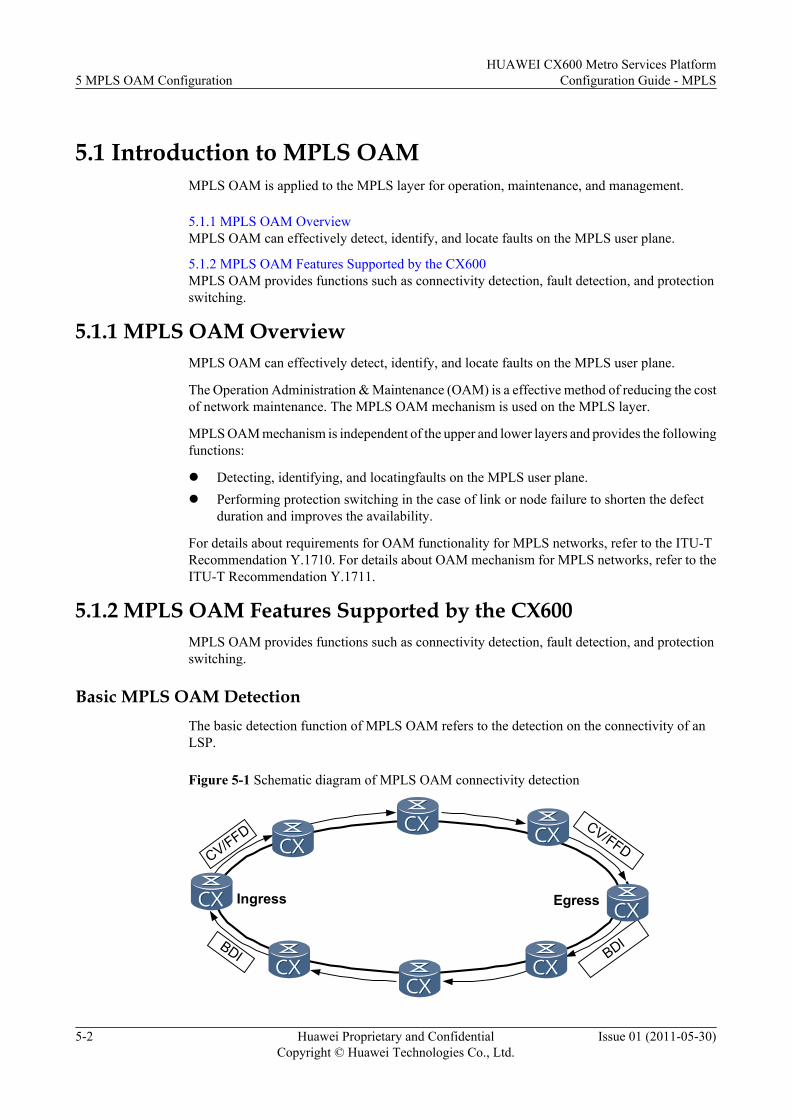
5.1 Introduction to MPLS OAMMPLS OAM is applied to the MPLS layer for operation, maintenance, and management.
5.1.1 MPLS OAM OverviewMPLS OAM can effectively detect, identify, and locate faults on the MPLS user plane.
5.1.2 MPLS OAM Features Supported by the CX600MPLS OAM provides functions such as connectivity detection, fault detection, and protectionswitching.
5.1.1 MPLS OAM OverviewMPLS OAM can effectively detect, identify, and locate faults on the MPLS user plane.
The Operation Administration & Maintenance (OAM) is a effective method of reducing the costof network maintenance. The MPLS OAM mechanism is used on the MPLS layer.
MPLS OAM mechanism is independent of the upper and lower layers and provides the followingfunctions:
l Detecting, identifying, and locatingfaults on the MPLS user plane.l Performing protection switching in the case of link or node failure to shorten the defect
duration and improves the availability.
For details about requirements for OAM functionality for MPLS networks, refer to the ITU-TRecommendation Y.1710. For details about OAM mechanism for MPLS networks, refer to theITU-T Recommendation Y.1711.
5.1.2 MPLS OAM Features Supported by the CX600MPLS OAM provides functions such as connectivity detection, fault detection, and protectionswitching.
Basic MPLS OAM DetectionThe basic detection function of MPLS OAM refers to the detection on the connectivity of anLSP.
Figure 5-1 Schematic diagram of MPLS OAM connectivity detection
Ingress Egress
CV/FFD
BDI
CV/FFD
BDI
5 MPLS OAM ConfigurationHUAWEI CX600 Metro Services Platform
Configuration Guide - MPLS
5-2 Huawei Proprietary and ConfidentialCopyright © Huawei Technologies Co., Ltd.
Issue 01 (2011-05-30)
As shown in Figure 5-1, procedures of MPLS OAM connectivity detection are as follows:
1. The ingress sends a CV or an FFD detection packet to the egress along the LSP to bedetected.
2. The egress judges whether the received packet is correct by comparing the packet type,frequency, and TTSI in the received packet with expected values recorded on the egress.It counts the number of the correct packets and the error packets received within a certainperiod, and thus monitors the LSP connectivity.
3. When the egress detects a defect on the LSP, it analyzes the defect type and sends aBackward Defect Indication (BDI) () packet carrying the defect information to the ingressthrough the backward tunnel. This enables the ingress to know the defect status in real time.If a protection group has been configured in the correct manner, the correspondingswitching is triggered.
Backward Tunnel
When configuring the basic OAM detection function, bind a backward tunnel to the detectedLSP.
A backward tunnel is an LSP with its ingress and egress being converse to the ingress and egressof the detected LSP. It also can be a non-MPLS path connected to the ingress and egress of thedetected LSP.
There are three types of backward tunnels:
l Private backward LSPl Shared backward LSPl A non-MPLS backward path
NOTE
At current, only LSPs can function as backward tunnels on the CX600l.
Auto-protocol Function of MPLS OAM
The ITU-T Y.1710 protocol has the following drawbacks:
l If the OAM function on the LSP ingress starts later than that on the LSP egress, or theegress is enabled with the OAM function but the ingress is not, the egress generates a Lossof Connectivity Verification defect (dLOCV) alarm.
l If the OAM function is disabled on the ingress whereas is enabled on the egress, the egressgenerates a dLOCV alarm .
l To modify the type of the detection packet or the frequency at which detection packets aresent, you must disable the OAM function on the egress and the ingress separately.
l OAM parameters need to be configured separately on the ingress and egress. This maycause the detection packet type and the frequency at which detection packets are sent to bedifferent on the ingress and egress.
The CX600 uses the OAM auto-protocol to solve problems existing in the ITU-T Y.1710.
The OAM auto-protocol is configured on the egress. It provides functions of initial packettriggering and dynamic enabling or disabling.
HUAWEI CX600 Metro Services PlatformConfiguration Guide - MPLS 5 MPLS OAM Configuration
Issue 01 (2011-05-30) Huawei Proprietary and ConfidentialCopyright © Huawei Technologies Co., Ltd.
5-3
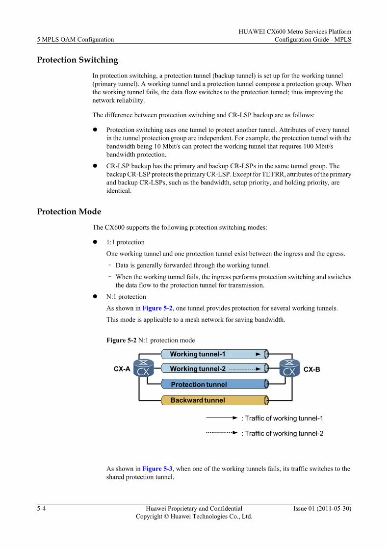
Protection Switching
In protection switching, a protection tunnel (backup tunnel) is set up for the working tunnel(primary tunnel). A working tunnel and a protection tunnel compose a protection group. Whenthe working tunnel fails, the data flow switches to the protection tunnel; thus improving thenetwork reliability.
The difference between protection switching and CR-LSP backup are as follows:
l Protection switching uses one tunnel to protect another tunnel. Attributes of every tunnelin the tunnel protection group are independent. For example, the protection tunnel with thebandwidth being 10 Mbit/s can protect the working tunnel that requires 100 Mbit/sbandwidth protection.
l CR-LSP backup has the primary and backup CR-LSPs in the same tunnel group. Thebackup CR-LSP protects the primary CR-LSP. Except for TE FRR, attributes of the primaryand backup CR-LSPs, such as the bandwidth, setup priority, and holding priority, areidentical.
Protection Mode
The CX600 supports the following protection switching modes:
l 1:1 protection
One working tunnel and one protection tunnel exist between the ingress and the egress.
– Data is generally forwarded through the working tunnel.
– When the working tunnel fails, the ingress performs protection switching and switchesthe data flow to the protection tunnel for transmission.
l N:1 protection
As shown in Figure 5-2, one tunnel provides protection for several working tunnels.
This mode is applicable to a mesh network for saving bandwidth.
Figure 5-2 N:1 protection mode
CX-A CX-B
Working tunnel-1
Working tunnel-2
Protection tunnel
Backward tunnel
: Traffic of working tunnel-1
: Traffic of working tunnel-2
As shown in Figure 5-3, when one of the working tunnels fails, its traffic switches to theshared protection tunnel.
5 MPLS OAM ConfigurationHUAWEI CX600 Metro Services Platform
Configuration Guide - MPLS
5-4 Huawei Proprietary and ConfidentialCopyright © Huawei Technologies Co., Ltd.
Issue 01 (2011-05-30)
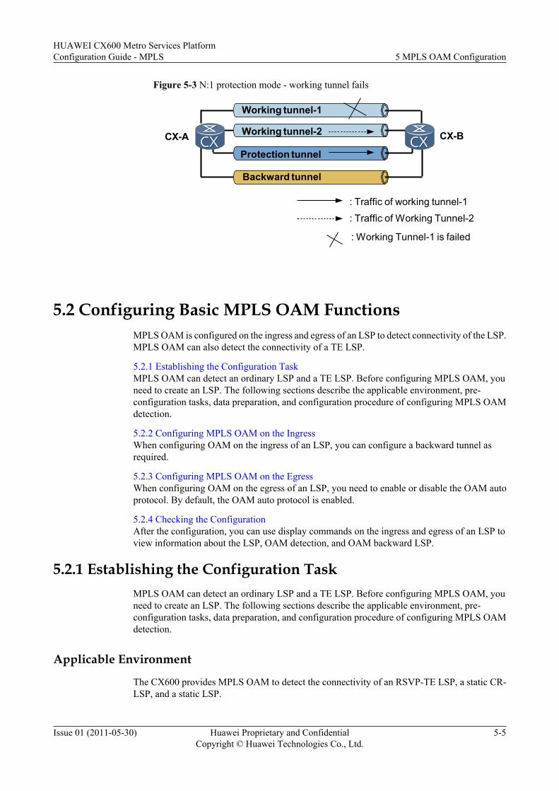
Figure 5-3 N:1 protection mode - working tunnel fails
CX-A CX-B
Working tunnel-1
Working tunnel-2
Protection tunnel
Backward tunnel
: Traffic of working tunnel-1: Traffic of Working Tunnel-2
: Working Tunnel-1 is failed
5.2 Configuring Basic MPLS OAM FunctionsMPLS OAM is configured on the ingress and egress of an LSP to detect connectivity of the LSP.MPLS OAM can also detect the connectivity of a TE LSP.
5.2.1 Establishing the Configuration TaskMPLS OAM can detect an ordinary LSP and a TE LSP. Before configuring MPLS OAM, youneed to create an LSP. The following sections describe the applicable environment, pre-configuration tasks, data preparation, and configuration procedure of configuring MPLS OAMdetection.
5.2.2 Configuring MPLS OAM on the IngressWhen configuring OAM on the ingress of an LSP, you can configure a backward tunnel asrequired.
5.2.3 Configuring MPLS OAM on the EgressWhen configuring OAM on the egress of an LSP, you need to enable or disable the OAM autoprotocol. By default, the OAM auto protocol is enabled.
5.2.4 Checking the ConfigurationAfter the configuration, you can use display commands on the ingress and egress of an LSP toview information about the LSP, OAM detection, and OAM backward LSP.
5.2.1 Establishing the Configuration TaskMPLS OAM can detect an ordinary LSP and a TE LSP. Before configuring MPLS OAM, youneed to create an LSP. The following sections describe the applicable environment, pre-configuration tasks, data preparation, and configuration procedure of configuring MPLS OAMdetection.
Applicable Environment
The CX600 provides MPLS OAM to detect the connectivity of an RSVP-TE LSP, a static CR-LSP, and a static LSP.
HUAWEI CX600 Metro Services PlatformConfiguration Guide - MPLS 5 MPLS OAM Configuration
Issue 01 (2011-05-30) Huawei Proprietary and ConfidentialCopyright © Huawei Technologies Co., Ltd.
5-5
To implement MPLS OAM functions, you need to create a backward LSP for bearing BDIpackets. The type of the backward LSP can be different from that of the tested LSP, but thebackward LSP must be bound to a TE tunnel.
Pre-configuration TasksBefore configuring basic MPLS OAM functions, complete the following tasks:
l Configuring basic MPLS functionsl Creating a forward LSP, the LSP to be detected by OAM and is bound to the TE tunnell Creating a backward LSP
NOTE
If the forward LSP is static and the backward LSP is dynamic, and the backward LSP is in the shared mode,you must specify lsrid ingress-lsr-id and tunnel-id tunnel-id when running the static-lsp egress commandor the static-cr-lsp egress command to create a forward LSP. For creating the LSP bound to a TE tunnel,refer to the chapter "MPLS TE Configuration."
Data PreparationTo configure basic MPLS OAM functions, you need the following data.
No. Data
1 Ingress: Number of tunnel interfaces bound to the detected LSP
2 (Optional) Ingress: backward tunnell If a static LSP or a static CR-LSP acts as the backward tunnel, the name of the
static LSP or the static CR-LSP is required.l If a dynamic LSP (RSVP-TE LSP) acts as the backward tunnel, the LSP ID and
tunnel ID are required .
3 Egress: Number of the tunnel interface that is bound to the backward LSP and theprotection mode
4 Egress: detected LSPl If a static LSP or a static CR-LSP is to be detected, the name of the LSP, LSR ID,
and tunnel ID are required.l If a dynamic LSP (RSVP-TE LSP) is to be detected, the LSR ID and the tunnel
ID are required.
5 (Optional) MPLS OAM parametersl Parameters for the ingress: detection type, frequency at which FFD packets are
sent, and priority of the detection packet.l Parameters for the egress: detection type, frequency at which FFD packets are
sent, status of the auto-protocol (enabled or disabled), timeout period of the auto-protocol, and frequency at which BDI packets are sent.
5 MPLS OAM ConfigurationHUAWEI CX600 Metro Services Platform
Configuration Guide - MPLS
5-6 Huawei Proprietary and ConfidentialCopyright © Huawei Technologies Co., Ltd.
Issue 01 (2011-05-30)
NOTE
l The backward LSP must be specified on the egress; otherwise, BDI packets cannot be correctly sentto the source end.
l If a shared backward LSP is used, you do not need to specify the backward LSP on the ingress.
5.2.2 Configuring MPLS OAM on the IngressWhen configuring OAM on the ingress of an LSP, you can configure a backward tunnel asrequired.
ContextDo as follows on the ingress of the LSP:
Procedure
Step 1 Run:system-view
The system view is displayed.
Step 2 Run:mpls
The MPLS view is displayed.
Step 3 Run:mpls oam
MPLS OAM is enabled globally.
By default, MPLS OAM is disabled globally.
Step 4 Run:quit
Return to the system view.
Step 5 Configure MPLS OAM parameters for the ingress.
If the PHP function is not configured when a backward LSP is set up, you must specify thebackward LSP when configuring parameters for the MPLS OAM ingress.
l If no backward LSP is specified, run:mpls oam ingress tunnel tunnel-number [ type { cv | ffd frequency ffd-fre } ] [ backward-lsp share ]
NOTE
Parameters of the backward LSP depend on the configuration of the egress.
l If a backward LSP is specified, run:mpls oam ingress tunnel tunnel-number [ type { cv | ffd frequency ffd-fre } ] backward-lsp { lsp-name lsp-name | lsr-id rev-ingress-lsr-id tunnel-id rev-tunnel-id } If the backward LSP is a static LSP or a static CR-LSP, you cannot configure it in privatemode.If lsrid ingress-lsr-id and tunnel-id tunnel-id are specified when you run the static-lspegress lsp-name incoming-interface interface-type interface-number in-label in-label
HUAWEI CX600 Metro Services PlatformConfiguration Guide - MPLS 5 MPLS OAM Configuration
Issue 01 (2011-05-30) Huawei Proprietary and ConfidentialCopyright © Huawei Technologies Co., Ltd.
5-7
[ lsrid ingress-lsr-id tunnel-id tunnel-id ] command or the static-cr-lsp egress lsp-nameincoming-interface interface-type interface-number in-label in-label [ lsrid ingress-lsr-idtunnel-id tunnel-id ] command to create a backward LSP, you can use these twoparametersspecify parameters in this step; otherwise, you can specifyonly the parameter lsp-name lsp-name.By default, the type of the detection packet is CV. The frequency at which CV packets aresent is one second.
Step 6 Run:mpls oam ingress enable { all | tunnel tunnel-number }
OAM is enabled on the ingress.
----End
5.2.3 Configuring MPLS OAM on the EgressWhen configuring OAM on the egress of an LSP, you need to enable or disable the OAM autoprotocol. By default, the OAM auto protocol is enabled.
ContextDo as follows on the egress of the LSP:
Procedure
Step 1 Run:system-view
The system view is displayed.
Step 2 Run:mpls
The MPLS view is displayed.
Step 3 Run:mpls oam
MPLS OAM is enabled globally.
Step 4 Run:quit
Return to the system view.
Step 5 Configure OAM parameters for the egress.l Run:
mpls oam egress { lsp-name lsp-name | lsr-id ingress-lsr-id tunnel-id tunnel-id } [ auto-protocol [ overtime over-time ] ] [ backward-lsp tunnel tunnel-number [ private | share ] [ bdi-frequency { detect-freq | per-second } ] ]
The auto-protocol extension of OAM is enabled.l Run:
mpls oam egress { lsp-name lsp-name | lsr-id ingress-lsr-id tunnel-id tunnel-id } type { cv | ffd frequency ffd-fre } [ backward-lsp tunnel tunnel-number [ private | share ] [ bdi-frequency { detect-freq | per-second } ] ]
5 MPLS OAM ConfigurationHUAWEI CX600 Metro Services Platform
Configuration Guide - MPLS
5-8 Huawei Proprietary and ConfidentialCopyright © Huawei Technologies Co., Ltd.
Issue 01 (2011-05-30)
OAM parameters is configured for the egress when the auto-protocol extension of OAM isdisabled.
If lsrid ingress-lsr-id and tunnel-id tunnel-id are specified when you run the static-lsp egresslsp-name incoming-interface interface-type interface-number in-label in-label [ lsrid ingress-lsr-id tunnel-id tunnel-id ] command or the static-cr-lsp egress lsp-name incoming-interface interface-type interface-number in-label in-label [ lsrid ingress-lsr-id tunnel-idtunnel-id ] command to create a forward tunnel, you can use these two parameters in this step;otherwise, you can specify only the parameter lsp-name lsp-name.
By default, the auto-protocol function of OAM is enabled. The timeout period for the first packetto wait for response is five minutes.
By default, the backward LSP is in the shared mode. When the backward LSP is a static LSP ora CR-LSP, it is in the private mode.
By default, the frequency at which BDI packets are sent through the backward LSP is detect-freq.
NOTE
If a shared backward LSP is used to enable the OAM auto-protocol extension in Step 5, Step 6 is notnecessary. When the egress receives the first CV/FFD packet, it automatically records the packet type andthe frequency at which CV/FFD packets are sent, and starts to detect the connectivity.
Step 6 Run:mpls oam egress enable { all | lsp-name lsp-name | lsr-id ingress-lsr-id tunnel-id tunnel-id }
OAM is enabled on the egress.
----End
5.2.4 Checking the ConfigurationAfter the configuration, you can use display commands on the ingress and egress of an LSP toview information about the LSP, OAM detection, and OAM backward LSP.
PrerequisiteThe configurations of basic MPLS OAM functions are complete.
Procedurel Run display mpls oam ingress { all | tunnel interface-number } [ slot slot-id | verbose ]
command to view MPLS OAM information on the ingress.
l Run display mpls oam egress { all | lsp-name lsp-name | lsr-id ingress-lsr-id tunnel-idtunnel-id } [ slot slot-id | verbose ] command to view MPLS OAM information on theegress.
----End
Example
If the configurations succeed, run the commands mentioned above and you can view thefollowing results:
HUAWEI CX600 Metro Services PlatformConfiguration Guide - MPLS 5 MPLS OAM Configuration
Issue 01 (2011-05-30) Huawei Proprietary and ConfidentialCopyright © Huawei Technologies Co., Ltd.
5-9
l Basic information about the LSP, including the tunnel name, LSP type, LSP ingress LSRID, and LSP tunnel ID
l Basic information about OAM, including the tunnel name, TTSI, packet type, andfrequency
l OAM detection information, including the packet type, frequency at which detectionpackets are sent, detection status, and defect status. If the link works properly, the detectionstatus is Start and the defect status is non-defect
l Information about backward LSP, including the sharing mode and configurations of thebackward LSP
5.3 Configuring MPLS OAM Protection SwitchingMPLS OAM protection switching enables a tunnel to protect one or more tunnels. The tunnelunder protection is a working tunnel, and the tunnel providing protection is a protection tunnel.When a protection tunnel protects one working tunnel, it indicates that tunnel protection is in1:1 mode.
5.3.1 Establishing the Configuration TaskMPLS OAM protection switching is a high-reliability technology applicable to tunnel protection.After one or more working tunnels and a protection tunnel are configured, the protection tunnelcan protect the working tunnel(s), which improves reliability of the working tunnel(s). Thefollowing sections describe the applicable environment, pre-configuration tasks, datapreparation, and configuration procedure of configuring MPLS OAM protection switching.
5.3.2 Configuring a Tunnel Protection GroupYou can configure a tunnel protection group for the primary tunnel on the ingress of a tunnel.In addition, you can configure the switchback delay time and the switchback mode. Theswitchback mode can be classified into the revertive mode and non-revertive mode. By default,revertive mode is used. In revertive mode, you can set the switchback delay time .
5.3.3 (Optional) Configuring the Protection Switching Trigger MechanismAfter configuring a tunnel protection group, you can configure a trigger mechanism of protectionswitching to force traffic to switch to the primary LSP or the backup LSP. Alternatively, youcan perform switchover manually.
5.3.4 (Optional) Enabling MPLS OAM to Detect Bidirectional LSPsWhen the working and the protection tunnels have backward LSPs, you can enable MPLS OAM.MPLS OAM to detect bidirectional LSPs.
5.3.5 Checking the ConfigurationAfter the configurations, you can use the display commands to view information about the tunnelprotection group and tunnel bindings.
5.3.1 Establishing the Configuration TaskMPLS OAM protection switching is a high-reliability technology applicable to tunnel protection.After one or more working tunnels and a protection tunnel are configured, the protection tunnelcan protect the working tunnel(s), which improves reliability of the working tunnel(s). Thefollowing sections describe the applicable environment, pre-configuration tasks, datapreparation, and configuration procedure of configuring MPLS OAM protection switching.
5 MPLS OAM ConfigurationHUAWEI CX600 Metro Services Platform
Configuration Guide - MPLS
5-10 Huawei Proprietary and ConfidentialCopyright © Huawei Technologies Co., Ltd.
Issue 01 (2011-05-30)
Applicable Environment
If the tunnel requires high availability, you can configure the MPLS OAM protection switchingto protect the tunnel.
MPLS OAM protection switching enables one tunnel to protect one or multiple tunnels. Thetunnel under protection is a working tunnel, and the tunnel providing protection is a protectiontunnel. A working tunnel and a protection tunnel compose a protection group.
One protection tunnel can protect one or more working tunnels. The protection mechanism inwhich one protection tunnel protects only one working tunnel is called 1:1 protection; oneprotection tunnel protects two or more working tunnel is called N:1 protection. "N" indicatesthe number of the working tunnels in the same protection group. Working tunnels in the sameprotection group use the same ingress and egress.
The CX600 supports 1:1 protection and N:1 protection.
l Working tunnel and protection tunnel
Attributes of every tunnel in the tunnel protection group are not related. For example, theprotection tunnel with the bandwidth being 50 Mbit/s can protect the working tunnel withthe bandwidth being 100 Mbit/s.
You can configure TE FRR on the working tunnel in the protection group to provide dualprotection for the working tunnel. The protection tunnel cannot serve as the TE FRRprimary tunnel to be protected by other tunnels. In addition, the protection tunnel cannotbe enabled with TE FRR.
l Protection switching trigger mechanism
The CX600 complies the following switch request criteria to initiate (or prevent) aprotection switching.
Table 5-1 Switch Request Criteria
Switch Request Order of Priority Description
Clear Highest Clears all switching requestsinitiated through commands,including forced switching andmanual switching. Traffic switchingis not performed in the case of signalfailure.
Signal Fail ↑ Automatically triggers the protectionswitching between the workingtunnel and the protection tunnel inthe case of a signal failure.
Manual Switch ↑ Switches traffic from the workingtunnel to the protection tunnel onlywhen the protection tunnel functionsproperly or switches traffic from theprotection tunnel to the workingtunnel only when the working tunnelfunctions properly.
HUAWEI CX600 Metro Services PlatformConfiguration Guide - MPLS 5 MPLS OAM Configuration
Issue 01 (2011-05-30) Huawei Proprietary and ConfidentialCopyright © Huawei Technologies Co., Ltd.
5-11
Switch Request Order of Priority Description
Wait To Restore ↑ Switches traffic from the protectiontunnel to the working tunnel after theworking tunnel recovers for a certainperiod specified by the wait-to-restore (WTR) timer.
No Request Lowest Indicates that there is no switchingrequest.
Pre-configuration Tasks
Before configuring MPLS OAM protection switching, complete the following tasks:
l Creating the working tunnel and protection tunnell Configuring basic MPLS OAM functions
Data Preparation
To configure MPLS OAM protection switching, you need the following data.
No. Data
1 Number of the working tunnel in the protection groupNOTE
The maximum number of working tunnels in a protection group is equal to or smaller than 16depending on the License.
2 Tunnel ID of the protection tunnel in the protection group
3 Parameters for the protection group, such as the hold off time, revertive mode, andWTR time
5.3.2 Configuring a Tunnel Protection GroupYou can configure a tunnel protection group for the primary tunnel on the ingress of a tunnel.In addition, you can configure the switchback delay time and the switchback mode. Theswitchback mode can be classified into the revertive mode and non-revertive mode. By default,revertive mode is used. In revertive mode, you can set the switchback delay time .
Context
Do as follows on the ingress of the tunnel:
Procedure
Step 1 Run:system-view
5 MPLS OAM ConfigurationHUAWEI CX600 Metro Services Platform
Configuration Guide - MPLS
5-12 Huawei Proprietary and ConfidentialCopyright © Huawei Technologies Co., Ltd.
Issue 01 (2011-05-30)
The system view is displayed.
Step 2 Run:interface tunnel tunnel-number
The tunnel interface view is displayed.
Step 3 Run:mpls te protection tunnel tunnel-id [ holdoff holdoff-time ] [ mode { non-revertive | revertive [ wtr wtr-time ] } ]
The working tunnel is added to the protection group.
Note the following parameters or concepts before perform this step:
l The tunnel-id indicates the tunnel ID of the protection tunnel.
l The hold-off time indicates the time between declaration of signal failure and the initializationof the protection switching algorithm. The hold-off time ranges from 0 to 10. By default, thehold-off time is 0. holdoff-time specifies the number of steps for the hold-off time. The valueof each step is 100, in milliseconds.
NOTE
Multiplying 100 milliseconds by holdoff-time, you can get the hold-off time.
l Non-revertive mode indicates that traffic does not switch back to the working tunnel eventhough the working tunnel recovers.
l Revertive mode indicates that traffic switches back to the working tunnel when the workingtunnel recovers.
By default, the protection group is in revertive mode.
l Wait to Restore time (WTR time) indicates the time to be waited before traffic switching.The WTR time ranges from 0 to 30 minutes. The default value is 12. The parameter wtr-time indicates the number of steps. The value of each step is 30, in seconds.
NOTEMultiplying 30 seconds by wtr-time, you can get the value of WTR time.
NOTEIf the number of the working tunnels in the same protection group is N, perform Step 2 and Step 3 for Ntimes by using different tunnel-number.
Step 4 Run:mpls te commit
The current configuration of the tunnel protection group is committed.
----End
Follow-up Procedure
Configurations described in this section are also applicable in modifying the configuration ofthe tunnel protection group.
Besides configuring a tunnel protection group to protect the working tunnel, you can configureTE FRR on the working tunnel in the protection group to provide dual protection for the workingtunnel. The protection tunnel cannot serve as the working tunnel to be protected by other tunnels.In addition, the protection tunnel cannot be enabled with TE FRR.
HUAWEI CX600 Metro Services PlatformConfiguration Guide - MPLS 5 MPLS OAM Configuration
Issue 01 (2011-05-30) Huawei Proprietary and ConfidentialCopyright © Huawei Technologies Co., Ltd.
5-13
5.3.3 (Optional) Configuring the Protection Switching TriggerMechanism
After configuring a tunnel protection group, you can configure a trigger mechanism of protectionswitching to force traffic to switch to the primary LSP or the backup LSP. Alternatively, youcan perform switchover manually.
Context
Pay attention to the switch request criteria before configuring the protection switching triggermechanism.
Do as follows on the ingress of the tunnel protection group as required:
Procedure
Step 1 Run:system-view
The system view is displayed.
Step 2 Run:interface tunnel tunnel-number
The tunnel interface view is displayed.
Step 3 Select one of the following protection switching trigger methods as required:
l To switch traffic to the working tunnel, run:mpls te protect-switch manual protect-lsp
l To switch traffic to the protection tunnel, run:mpls te protect-switch manual work-lsp
l To cancel the configuration of the protection switching trigger mechanism, run:mpls te protect-switch clear
Step 4 Run:mpls te commit
The current configuration is committed.
----End
5.3.4 (Optional) Enabling MPLS OAM to Detect Bidirectional LSPsWhen the working and the protection tunnels have backward LSPs, you can enable MPLS OAM.MPLS OAM to detect bidirectional LSPs.
Context
Before performing the following configurations, configure backward LSPs for the working andprotection tunnels. The working LSP and protection LSP, and their reverse LSPs composebidirectional LSPa.
5 MPLS OAM ConfigurationHUAWEI CX600 Metro Services Platform
Configuration Guide - MPLS
5-14 Huawei Proprietary and ConfidentialCopyright © Huawei Technologies Co., Ltd.
Issue 01 (2011-05-30)
NOTE
The backward LSP must be a static LSP or static CR-LSP. The working LSP and protection LSP can be astatic LSP, static CR-LSP, or RSVP LSP.
It is recommended that the LSP and the backward LSP of a bidirectional LSP be both static LSPs or bothstatic CR-LSPs; the protection LSP and the backward LSP are all static LSPs or all static CR-LSPs.
On the ingress, the inbound interface of the backward LSP and the outbound interface of the working LSPor the protection LSP must be the same.
Procedurel Enable MPLS OAM to detect the bidirectional LSP of the working tunnel.
Do as follows on the ingress of the working tunnel:
1. Run:system-view
The system view is displayed.
2. Run:interface tunnel tunnel-number
The tunnel interface view of the working tunnel is displayed.
3. Run:mpls te reverse-lsp lsp-name lsp-name
The backward LSP of the working tunnel is specified.
4. Run:mpls te commit
The current configuration of the working tunnel is committed.
l Enable MPLS OAM to detect the bidirectional LSP of the protection tunnel.
Do as follows on the ingress of the protection tunnel:
1. Run:system-view
The system view is displayed.
2. Run:interface tunnel tunnel-number
The tunnel interface view of the protection tunnel is displayed.
3. Run:mpls te reverse-lsp lsp-name lsp-name
The backward LSP of the protection tunnel is specified.
4. Run:mpls te commit
The current configuration of the protection tunnel is committed.
----End
HUAWEI CX600 Metro Services PlatformConfiguration Guide - MPLS 5 MPLS OAM Configuration
Issue 01 (2011-05-30) Huawei Proprietary and ConfidentialCopyright © Huawei Technologies Co., Ltd.
5-15
5.3.5 Checking the ConfigurationAfter the configurations, you can use the display commands to view information about the tunnelprotection group and tunnel bindings.
PrerequisiteThe configurations of the MPLS OAM protection switching function are complete.
Procedurel Run display mpls te protection tunnel { all | tunnel-id | interface tunnel interface-
number } [ verbose ] command to check information about a tunnel protection group.l Run display mpls te protection binding protect-tunnel { tunnel-id | interface tunnel
interface-number } command to check the protection relationship of the tunnel.
----End
ExampleAfter the configuration succeeds, run the preceding commands to view information about theprotection group.
5.4 Maintaining MPLS OAMYou can use display commands to monitor MPLS OAM and the tunnel protection group.
5.4.1 Monitoring the Running of MPLS OAMYou can use display commands to view the MPLS OAM operation status including the statusof OAM-enabled LSPs on the ingress and egress.
5.4.2 Monitoring the Running of Protection GroupYou can use display commands to view the operation of a tunnel protection group andinformation about tunnels in the tunnel protection group.
5.4.1 Monitoring the Running of MPLS OAMYou can use display commands to view the MPLS OAM operation status including the statusof OAM-enabled LSPs on the ingress and egress.
ContextIn routine maintenance, you can run the following commands in any view to check the MPLSOAM operation status.
Procedurel Run the display mpls oam egress { all | lsp-name lsp-name | lsr-id ingress-lsr-id tunnel-
id tunnel-id } [ slot slot-id | verbose ] command to view information about the currentstatus and configuration of the OAM-enabled LSP on the egress.
l Run the display mpls oam ingress { all | tunnel tunnel-number } [ slot slot-id |verbose ] command to view information about the MPLS OAM parameters and status ofthe LSP on the ingress.
5 MPLS OAM ConfigurationHUAWEI CX600 Metro Services Platform
Configuration Guide - MPLS
5-16 Huawei Proprietary and ConfidentialCopyright © Huawei Technologies Co., Ltd.
Issue 01 (2011-05-30)
l Run the display mpls oam oam-index index-value [ slot slot-id ] command to viewinformation about parameters and status of MPLS OAM.
----End
5.4.2 Monitoring the Running of Protection GroupYou can use display commands to view the operation of a tunnel protection group andinformation about tunnels in the tunnel protection group.
ContextIn routine maintenance, you can run the following commands in any view to check the operatingstatus of the protection group.
Procedurel Run the display mpls te protection tunnel { all | tunnel-id | interface tunnel interface-
number } [ verbose ] command to view information about the tunnel protection group.l Run the display mpls te protection binding protect-tunnel { tunnel-id | interface
tunnel interface-number } command to view information about tunnels in the tunnelprotection group.
----End
5.5 Configuration ExamplesThe following sections provide several examples for configuring MPLS OAM to detect LSPsand configuring the association between MPLS OAM and a protection group for performingprotection switching.
Follow-up ProcedureNOTE
This document takes interface numbers and link types of the CX600-X8 as an example. In applications,the actual interface numbers and link types may be different from those used in this document.
5.5.1 Example for Configuring MPLS OAM to Detect a Static LSPThe section provides an example for creating a static LSP and configuring MPLS OAM to detectconnectivity of the static LSP.
5.5.2 Example for Configuring MPLS OAM Protection SwitchingThis section provides an example for creating a working tunnel and a protection tunnel, andconfiguring MPLS OAM protection switching.
5.5.1 Example for Configuring MPLS OAM to Detect a Static LSPThe section provides an example for creating a static LSP and configuring MPLS OAM to detectconnectivity of the static LSP.
Networking RequirementsAs shown in Figure 5-4, on an MPLS network, a static LSP along LSR A -> LSR B -> LSR Cis set up.
HUAWEI CX600 Metro Services PlatformConfiguration Guide - MPLS 5 MPLS OAM Configuration
Issue 01 (2011-05-30) Huawei Proprietary and ConfidentialCopyright © Huawei Technologies Co., Ltd.
5-17
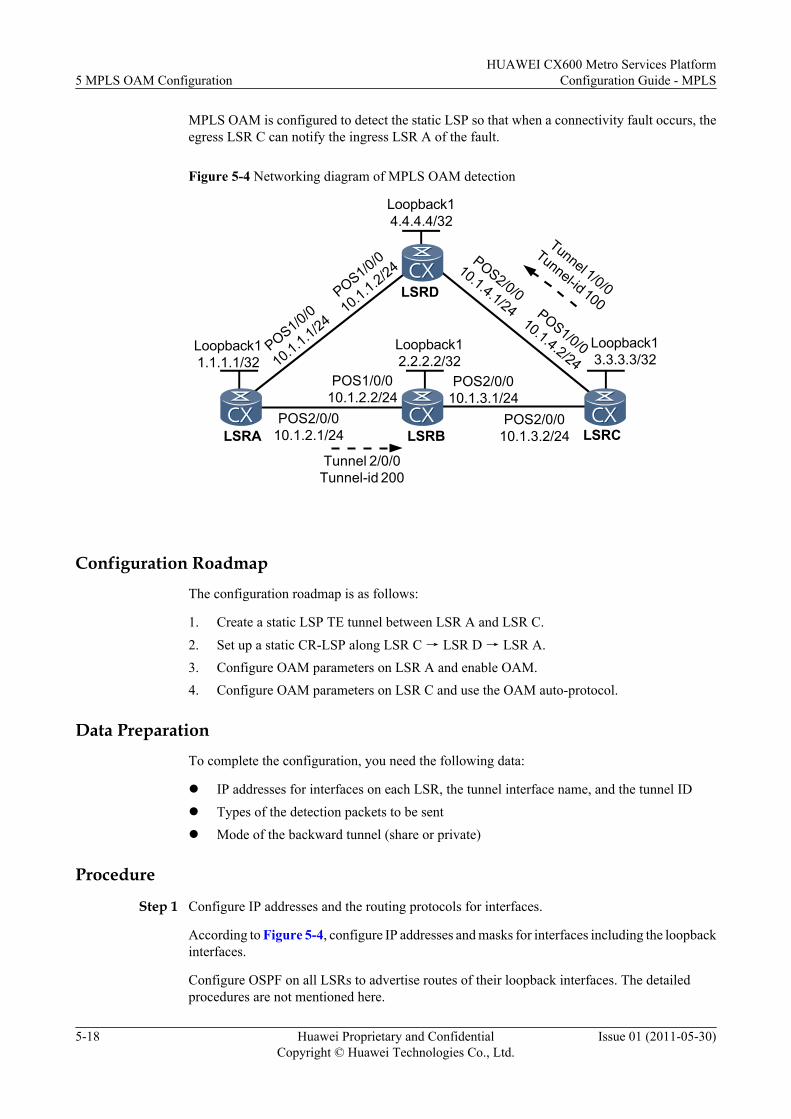
MPLS OAM is configured to detect the static LSP so that when a connectivity fault occurs, theegress LSR C can notify the ingress LSR A of the fault.
Figure 5-4 Networking diagram of MPLS OAM detection
POS2/0/010.1.2.1/24
POS1/0/010.1.2.2/24
POS2/0/010.1.3.2/24
POS2/0/010.1.3.1/24
LSRA LSRC
POS1/0/0
10.1.4.2/24POS1/0/0
10.1.1.1/24
POS1/0/0
10.1.1.2/24POS2/0/0
10.1.4.1/24
Tunnel 2/0/0Tunnel-id 200
Loopback11.1.1.1/32
Loopback14.4.4.4/32
Loopback13.3.3.3/32
Loopback12.2.2.2/32
LSRD
LSRB
Tunnel 1/0/0
Tunnel-id 100
Configuration Roadmap
The configuration roadmap is as follows:
1. Create a static LSP TE tunnel between LSR A and LSR C.2. Set up a static CR-LSP along LSR C → LSR D → LSR A.3. Configure OAM parameters on LSR A and enable OAM.4. Configure OAM parameters on LSR C and use the OAM auto-protocol.
Data Preparation
To complete the configuration, you need the following data:
l IP addresses for interfaces on each LSR, the tunnel interface name, and the tunnel IDl Types of the detection packets to be sentl Mode of the backward tunnel (share or private)
Procedure
Step 1 Configure IP addresses and the routing protocols for interfaces.
According to Figure 5-4, configure IP addresses and masks for interfaces including the loopbackinterfaces.
Configure OSPF on all LSRs to advertise routes of their loopback interfaces. The detailedprocedures are not mentioned here.
5 MPLS OAM ConfigurationHUAWEI CX600 Metro Services Platform
Configuration Guide - MPLS
5-18 Huawei Proprietary and ConfidentialCopyright © Huawei Technologies Co., Ltd.
Issue 01 (2011-05-30)
After the configuration, LSRs can ping each other. Run the display ip routing-table commandon each LSR to display routes to each LSR-ID.
Take the display on LSR A as an example.<LSRA> display ip routing-tableRoute Flags: R - relay, D - download to fib------------------------------------------------------------------------------Routing Tables: Public Destinations : 14 Routes : 15Destination/Mask Proto Pre Cost Flags NextHop Interface 1.1.1.1/32 Direct 0 0 D 127.0.0.1 InLoopBack0 2.2.2.2/32 OSPF 10 2 D 10.1.2.2 Pos2/0/0 3.3.3.3/32 OSPF 10 3 D 10.1.1.2 Pos1/0/0 OSPF 10 3 D 10.1.2.2 Pos2/0/0 4.4.4.4/32 OSPF 10 2 D 10.1.1.2 Pos1/0/0 10.1.1.0/24 Direct 0 0 D 10.1.1.1 Pos1/0/0 10.1.1.1/32 Direct 0 0 D 127.0.0.1 InLoopBack0 10.1.1.2/32 Direct 0 0 D 10.1.1.2 Pos1/0/0 10.1.2.0/24 Direct 0 0 D 10.1.2.1 Pos2/0/0 10.1.2.1/32 Direct 0 0 D 127.0.0.1 InLoopBack0 10.1.2.2/32 Direct 0 0 D 10.1.2.2 Pos2/0/0 10.1.3.0/24 OSPF 10 2 D 10.1.2.2 Pos2/0/0 10.1.4.0/24 OSPF 10 2 D 10.1.1.2 Pos1/0/0 127.0.0.0/8 Direct 0 0 D 127.0.0.1 InLoopBack0 127.0.0.1/32 Direct 0 0 D 127.0.0.1 InLoopBack0
Step 2 Set up a static LSP to be detected.
# Configure basic MPLS and MPLS TE functions on LSR A.<LSRA> system-view[LSRA] mpls lsr-id 1.1.1.1[LSRA] mpls[LSRA-mpls] mpls te[LSRA-mpls] quit[LSRA] interface pos 1/0/0[LSRA-Pos1/0/0] mpls[LSRA-Pos1/0/0] mpls te[LSRA-Pos1/0/0] quit[LSRA] interface pos 2/0/0[LSRA-Pos2/0/0] mpls[LSRA-Pos2/0/0] mpls te[LSRA-Pos2/0/0] quit
Other LSRs have the same configuration as LSR A.
# Create an MPLS TE tunnel that is based on the static LSP from LSR A to LSR C.[LSRA] interface tunnel 2/0/0[LSRA-Tunnel2/0/0] ip address unnumbered interface loopback 1[LSRA-Tunnel2/0/0] tunnel-protocol mpls te[LSRA-Tunnel2/0/0] destination 3.3.3.3[LSRA-Tunnel2/0/0] mpls te tunnel-id 200[LSRA-Tunnel2/0/0] mpls te signal-protocol static[LSRA-Tunnel2/0/0] mpls te commit[LSRA-Tunnel2/0/0] quit
# Configure LSR A to be the ingress of the static LSP and enable the TE tunnel.[LSRA] static-lsp ingress tunnel-interface tunnel 2/0/0 destination 3.3.3.3 nexthop 10.1.2.2 out-label 20
# Configure LSR B to be the transit node of the static LSP.<LSRB> system-view[LSRB] static-lsp transit oamlsp incoming-interface pos 1/0/0 in-label 20 nexthop 10.1.3.2 out-label 30
# Configure LSR C to be the egress of the static LSP and specify lsr-id and tunnel-id.
HUAWEI CX600 Metro Services PlatformConfiguration Guide - MPLS 5 MPLS OAM Configuration
Issue 01 (2011-05-30) Huawei Proprietary and ConfidentialCopyright © Huawei Technologies Co., Ltd.
5-19
<LSRC> system-view[LSRC] static-lsp egress oamlsp incoming-interface pos 2/0/0 in-label 30 lsrid 1.1.1.1 tunnel-id 200
After the configuration, run the display mpls te tunnel-interface command on LSR A, and youcan view that the TE tunnel is Up.
[LSRA] display mpls te tunnel-interface================================================================ Tunnel2/0/0 ================================================================Tunnel State Desc : UP Active LSP : Primary LSP Session ID : 200 Ingress LSR ID : 1.1.1.1 Egress LSR ID: 3.3.3.3 Admin State : UP Oper State : UP Primary LSP State : UP Main LSP State : READY LSP ID : 1
Run the display mpls static-lsp command on LSR A, and you can view that the static LSPcorresponding to Tunnel 2/0/0 is Up.
[LSRA] display mpls static-lspTOTAL : 1 STATIC LSP(S)UP : 1 STATIC LSP(S)DOWN : 0 STATIC LSP(S) Name FEC I/O Label I/O If StatTunnel2/0/0 3.3.3.3/32 NULL/20 -/Pos2/0/0 Up
Step 3 Set up a backward tunnel.
# Create an MPLS TE tunnel that is based on the static CR-LSP from LSR C to LSR A.
[LSRC] interface Tunnel 1/0/0[LSRC-Tunnel1/0/0] ip address unnumbered interface loopback 1[LSRC-Tunnel1/0/0] tunnel-protocol mpls te[LSRC-Tunnel1/0/0] destination 1.1.1.1[LSRC-Tunnel1/0/0] mpls te tunnel-id 100[LSRC-Tunnel1/0/0] mpls te signal-protocol cr-static[LSRC-Tunnel1/0/0] mpls te commit[LSRC-Tunnel1/0/0] quit
# Configure LSR C to be the ingress of the static CR-LSP.
[LSRC] static-cr-lsp ingress tunnel-interface tunnel1/0/0 destination 1.1.1.1 nexthop 10.1.4.1 out-label 70
# Configure LSR D to be the transit node of the CR-LSP.
<LSRD> system-view[LSRD] static-cr-lsp transit tunnel1/0/0 incoming-interface pos 2/0/0 in-label 70 nexthop 10.1.1.1 out-label 80
# Configure LSR A to be the egress of the static CR-LSP and specify lsr-id and tunnel-id.
[LSRA] static-cr-lsp egress Tunnel1/0/0 incoming-interface pos 1/0/0 in-label 80 lsrid 3.3.3.3 tunnel-id 100
After the configuration, run the display mpls te tunnel-interface command on LSR C, and youcan view that the backward tunnel is Up.
[LSRC] display mpls te tunnel-interface================================================================ Tunnel1/0/0 ================================================================Tunnel State Desc : UP Active LSP : Primary LSP Session ID : 100 Ingress LSR ID : 3.3.3.3 Egress LSR ID: 1.1.1.1
5 MPLS OAM ConfigurationHUAWEI CX600 Metro Services Platform
Configuration Guide - MPLS
5-20 Huawei Proprietary and ConfidentialCopyright © Huawei Technologies Co., Ltd.
Issue 01 (2011-05-30)
Admin State : UP Oper State : UP Primary LSP State : UP Main LSP State : READY LSP ID : 1
Run the display mpls static-cr-lsp command on LSR C, and you can view that the static CR-LSR is Up.
[LSRC] display mpls static-cr-lspTOTAL : 1 STATIC CRLSP(S)UP : 1 STATIC CRLSP(S)DOWN : 0 STATIC CRLSP(S)Name FEC I/O Label I/O If StatTunnel1/0/0 1.1.1.1/32 NULL/70 -/Pos1/0/0 Up
Step 4 Configure MPLS OAM.
# Configure MPLS OAM for the ingress on LSR A. By default, sending CV packets is enabled.Parameters for the backward tunnel depend on the configuration of the egress.
[LSRA] mpls[LSRA-mpls] mpls oam[LSRA-mpls] quit[LSRA] mpls oam ingress Tunnel 2/0/0[LSRA] mpls oam ingress enable all
# Configure MPLS OAM on LSR C.
[LSRC] mpls[LSRC-mpls] mpls oam[LSRC-mpls] quit
# Configure the OAM auto-protocol on LSR C to detect the LSP named oamlsp. The backwardtunnel is the LSP bound to tunnel 1/0/0. It is in the private mode.
[LSRC] mpls oam egress lsp-name oamlsp auto-protocol backward-lsp tunnel 1/0/0 private
After the OAM auto-protocol is configured on the egress, OAM is enabled automatically whenthe egress receives the first correct detention packet.
After the configuration, check the MPLS OAM parameters and status of LSPs on LSR A andLSR C. You can view that both ingress and egress are active in normal detection status.
[LSRA] display mpls oam ingress all verbose-------------------------------------------------------------------------Verbose information about the 1th oam at the ingress-------------------------------------------------------------------------lsp basic information: oam basic information:----------------------------------- -----------------------------------Tunnel-name : Tunnel2/0/0 Oam-Index : 256Lsp signal status : Up Oam select board : 1Lsp establish type : Static lsp Enable-state : Manual enableLsp ingress lsr-id : 1.1.1.1 Ttsi/lsr-id : 1.1.1.1Lsp tnl-id/Lsp-id : 200/1 Ttsi/tunnel-id : 200oam detect information: oam backward information:----------------------------------- -----------------------------------Type : CV Share attribute : PrivateFrequency : 1 s Lsp-name : Tunnel1/0/0Detect-state : Start Lsp ingress lsr-id : 3.3.3.3Defect-state : Non-defect Lsp tnl-id/lsp id : 100/1Available-state : available Lsp-inLabel : 80Unavailable time (s): 0 Lsp signal status : Up-------------------------------------------------------------------------Total Oam Num: 1Total Start Oam Num: 1Total Defect Oam Num: 0Total Unavaliable Oam Num: 0[LSRC] display mpls oam egress all verbose
HUAWEI CX600 Metro Services PlatformConfiguration Guide - MPLS 5 MPLS OAM Configuration
Issue 01 (2011-05-30) Huawei Proprietary and ConfidentialCopyright © Huawei Technologies Co., Ltd.
5-21
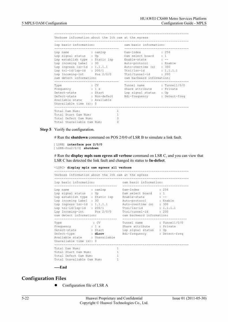
-------------------------------------------------------------------------Verbose information about the 1th oam at the egress-------------------------------------------------------------------------lsp basic information: oam basic information:----------------------------------- -----------------------------------Lsp name : oamlsp Oam-Index : 256Lsp signal status : Up Oam select board : 1Lsp establish type : Static lsp Enable-state : --Lsp incoming Label : 30 Auto-protocol : EnableLsp ingress lsr-id : 1.1.1.1 Auto-overtime (s) : 300Lsp tnl-id/lsp-id : 200/1 Ttsi/lsr-id : 1.1.1.1Lsp Incoming-int Pos 2/0/0 Ttsi/tunnel-id : 200oam detect information: oam backward information:----------------------------------- -----------------------------------Type : CV Tunnel name : Tunnel1/0/0Frequency : 1 s Share attribute : PrivateDetect-state : Start Lsp signal status : UpDefect-state : Non-defect Bdi-frequency : Detect-freqAvailable state : AvailableUnavailable time (s): 0-------------------------------------------------------------------------Total Oam Num: 1Total Start Oam Num: 1Total Defect Oam Num: 0Total Unavaliable Oam Num: 0
Step 5 Verify the configuration.
# Run the shutdown command on POS 2/0/0 of LSR B to simulate a link fault.
[LSRB] interface pos 2/0/0[LSRB-Pos2/0/0] shutdown
# Run the display mpls oam egress all verbose command on LSR C, and you can view thatLSR C has detected the link fault and changed its status to In-defect.
<LSRC> display mpls oam egress all verbose-------------------------------------------------------------------------Verbose information about the 1th oam at the egress-------------------------------------------------------------------------lsp basic information: oam basic information:---------------------------------- ------------------------------------Lsp name : oamlsp Oam-Index : 256Lsp signal status : Up Oam select board : 1Lsp establish type : Static lsp Enable-state : --Lsp incoming Label : 30 Auto-protocol : EnableLsp ingress lsr-id : 1.1.1.1 Auto-overtime (s) : 300Lsp tnl-id/lsp-id : 200/1 Ttsi/lsr-id : 1.1.1.1Lsp Incoming-int Pos 2/0/0 Ttsi/tunnel-id : 200oam detect information: oam backward information:---------------------------------- -----------------------------------Type : CV Tunnel name : Tunnel1/0/0Frequency : 1 s Share attribute : PrivateDetect-state : Start Lsp signal status : UpDefect-type : dLocv Bdi-frequency : Detect-freqAvailable state : UnavailableUnavailable time (s): 0-------------------------------------------------------------------------Total Oam Num: 1Total Start Oam Num: 1Total Defect Oam Num: 1Total Unavaliable Oam Num: 1
----End
Configuration Filesl Configuration file of LSR A
5 MPLS OAM ConfigurationHUAWEI CX600 Metro Services Platform
Configuration Guide - MPLS
5-22 Huawei Proprietary and ConfidentialCopyright © Huawei Technologies Co., Ltd.
Issue 01 (2011-05-30)
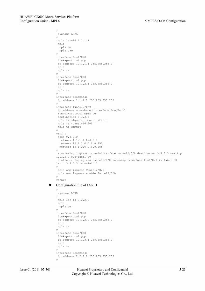
# sysname LSRA# mpls lsr-id 1.1.1.1 mpls mpls te mpls oam#interface Pos1/0/0 link-protocol ppp ip address 10.1.1.1 255.255.255.0 mpls mpls te#interface Pos2/0/0 link-protocol ppp ip address 10.1.2.1 255.255.255.0 mpls mpls te#interface LoopBack1 ip address 1.1.1.1 255.255.255.255#interface Tunnel2/0/0 ip address unnumbered interface LoopBack1 tunnel-protocol mpls te destination 3.3.3.3 mpls te signal-protocol static mpls te tunnel-id 200 mpls te commit#ospf 1 area 0.0.0.0 network 1.1.1.1 0.0.0.0 network 10.1.1.0 0.0.0.255 network 10.1.2.0 0.0.0.255# static-lsp ingress tunnel-interface Tunnel2/0/0 destination 3.3.3.3 nexthop 10.1.2.2 out-label 20 static-cr-lsp egress tunnel1/0/0 incoming-interface Pos1/0/0 in-label 80 lsrid 3.3.3.3 tunnel-id 1# mpls oam ingress Tunnel2/0/0 mpls oam ingress enable Tunnel2/0/0#return
l Configuration file of LSR B# sysname LSRB# mpls lsr-id 2.2.2.2 mpls mpls te#interface Pos1/0/0 link-protocol ppp ip address 10.1.2.2 255.255.255.0 mpls mpls te#interface Pos2/0/0 link-protocol ppp ip address 10.1.3.1 255.255.255.0 mpls mpls te#interface LoopBack1 ip address 2.2.2.2 255.255.255.255#
HUAWEI CX600 Metro Services PlatformConfiguration Guide - MPLS 5 MPLS OAM Configuration
Issue 01 (2011-05-30) Huawei Proprietary and ConfidentialCopyright © Huawei Technologies Co., Ltd.
5-23
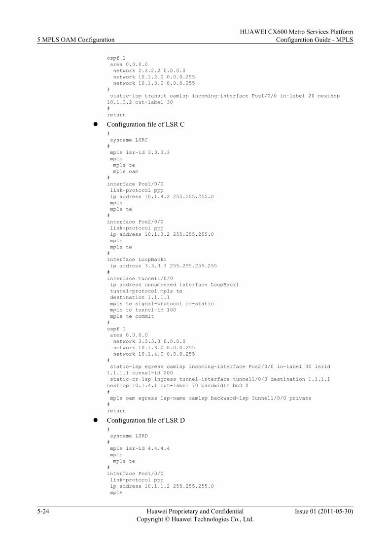
ospf 1 area 0.0.0.0 network 2.2.2.2 0.0.0.0 network 10.1.2.0 0.0.0.255 network 10.1.3.0 0.0.0.255# static-lsp transit oamlsp incoming-interface Pos1/0/0 in-label 20 nexthop 10.1.3.2 out-label 30#return
l Configuration file of LSR C# sysname LSRC# mpls lsr-id 3.3.3.3 mpls mpls te mpls oam#interface Pos1/0/0 link-protocol ppp ip address 10.1.4.2 255.255.255.0 mpls mpls te#interface Pos2/0/0 link-protocol ppp ip address 10.1.3.2 255.255.255.0 mpls mpls te#interface LoopBack1 ip address 3.3.3.3 255.255.255.255#interface Tunnel1/0/0 ip address unnumbered interface LoopBack1 tunnel-protocol mpls te destination 1.1.1.1 mpls te signal-protocol cr-static mpls te tunnel-id 100 mpls te commit#ospf 1 area 0.0.0.0 network 3.3.3.3 0.0.0.0 network 10.1.3.0 0.0.0.255 network 10.1.4.0 0.0.0.255# static-lsp egress oamlsp incoming-interface Pos2/0/0 in-label 30 lsrid 1.1.1.1 tunnel-id 200 static-cr-lsp ingress tunnel-interface tunnel1/0/0 destination 1.1.1.1 nexthop 10.1.4.1 out-label 70 bandwidth bc0 0# mpls oam egress lsp-name oamlsp backward-lsp Tunnel1/0/0 private#return
l Configuration file of LSR D# sysname LSRD# mpls lsr-id 4.4.4.4 mpls mpls te#interface Pos1/0/0 link-protocol ppp ip address 10.1.1.2 255.255.255.0 mpls
5 MPLS OAM ConfigurationHUAWEI CX600 Metro Services Platform
Configuration Guide - MPLS
5-24 Huawei Proprietary and ConfidentialCopyright © Huawei Technologies Co., Ltd.
Issue 01 (2011-05-30)
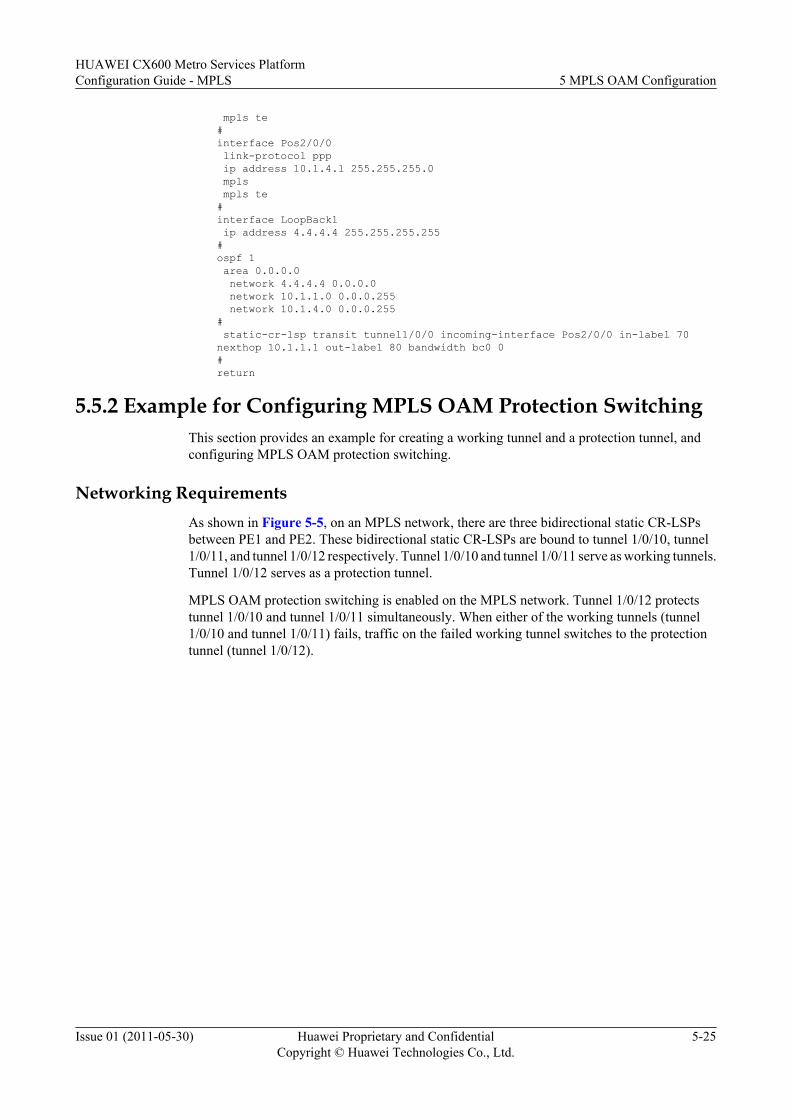
mpls te#interface Pos2/0/0 link-protocol ppp ip address 10.1.4.1 255.255.255.0 mpls mpls te#interface LoopBack1 ip address 4.4.4.4 255.255.255.255#ospf 1 area 0.0.0.0 network 4.4.4.4 0.0.0.0 network 10.1.1.0 0.0.0.255 network 10.1.4.0 0.0.0.255# static-cr-lsp transit tunnel1/0/0 incoming-interface Pos2/0/0 in-label 70 nexthop 10.1.1.1 out-label 80 bandwidth bc0 0#return
5.5.2 Example for Configuring MPLS OAM Protection SwitchingThis section provides an example for creating a working tunnel and a protection tunnel, andconfiguring MPLS OAM protection switching.
Networking RequirementsAs shown in Figure 5-5, on an MPLS network, there are three bidirectional static CR-LSPsbetween PE1 and PE2. These bidirectional static CR-LSPs are bound to tunnel 1/0/10, tunnel1/0/11, and tunnel 1/0/12 respectively. Tunnel 1/0/10 and tunnel 1/0/11 serve as working tunnels.Tunnel 1/0/12 serves as a protection tunnel.
MPLS OAM protection switching is enabled on the MPLS network. Tunnel 1/0/12 protectstunnel 1/0/10 and tunnel 1/0/11 simultaneously. When either of the working tunnels (tunnel1/0/10 and tunnel 1/0/11) fails, traffic on the failed working tunnel switches to the protectiontunnel (tunnel 1/0/12).
HUAWEI CX600 Metro Services PlatformConfiguration Guide - MPLS 5 MPLS OAM Configuration
Issue 01 (2011-05-30) Huawei Proprietary and ConfidentialCopyright © Huawei Technologies Co., Ltd.
5-25
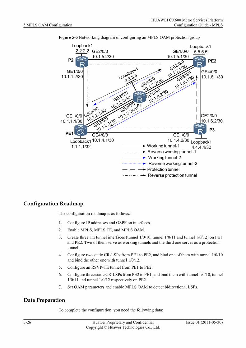
Figure 5-5 Networking diagram of configuring an MPLS OAM protection group
GE1/0/010.1.1.1/30
GE1/0/010.1.1.2/30
GE1/0/010.1.4.2/30
GE4/0/010.1.4.1/30
GE2/0/010.1.5.2/30
GE1/0/010.1.5.1/30
GE4/0/010.1.6.1/30
GE2/0/010.1.6.2/30
PE1
PE2
P1
P2
P3
Loopback12.2.2.2
Loopback15.5.5.5
Loopback11.1.1.1/32
Loopback14.4.4.4/32
Loopback1
3.3.3.3
Working tunnel-1Reverse working tunnel-1Working tunnel-2Reverse working tunnel-2
Protection tunnelReverse protection tunnel
GE2/0/0
10.1.2.1/30
GE2/0/0
10.1.2.2/30
GE3/0/0
10.1.3.1/30
GE3/0/0
10.1.3.2/30
GE1/0/0
10.1.8.2/30
GE3/0/0
10.1.8.1/30
GE4/0/0
10.1.7.2/30
GE2/0/0
10.1.7.1/30
Configuration Roadmap
The configuration roadmap is as follows:
1. Configure IP addresses and OSPF on interfaces
2. Enable MPLS, MPLS TE, and MPLS OAM.
3. Create three TE tunnel interfaces (tunnel 1/0/10, tunnel 1/0/11 and tunnel 1/0/12) on PE1and PE2. Two of them serve as working tunnels and the third one serves as a protectiontunnel.
4. Configure two static CR-LSPs from PE1 to PE2, and bind one of them with tunnel 1/0/10and bind the other one with tunnel 1/0/12.
5. Configure an RSVP-TE tunnel from PE1 to PE2.
6. Configure three static CR-LSPs from PE2 to PE1, and bind them with tunnel 1/0/10, tunnel1/0/11 and tunnel 1/0/12 respectively on PE2.
7. Set OAM parameters and enable MPLS OAM to detect bidirectional LSPs.
Data Preparation
To complete the configuration, you need the following data:
5 MPLS OAM ConfigurationHUAWEI CX600 Metro Services Platform
Configuration Guide - MPLS
5-26 Huawei Proprietary and ConfidentialCopyright © Huawei Technologies Co., Ltd.
Issue 01 (2011-05-30)
l IP addresses of interfaces, tunnel interface names, and tunnel IDsl Types of packets to be detected by MPLS OAMl Parameters for a protection group, including the delay of the protection switching, revertive
mode, and WTR time
Procedure
Step 1 Configure IP addresses and routing protocols on interfaces.
As shown in Figure 5-5, configure IP addresses and masks for interfaces, including loopbackinterfaces.
Configure the OSPF protocol on all LSRs to advertise host routes of their loopback interfaces.The detailed configuration is not mentioned here.
After the configuration, LSRs can ping the LSR ID of each other.
Step 2 Enable MPLS and MPLS TE globally and on the physical interfaces.
The detailed configuration is not mentioned here.
Step 3 Configure TE tunnel interfaces.
# On PE1 and PE2, configure tunnel 1/0/10 and tunnel 1/0/11 as working tunnels and tunnel1/0/12 as a protection tunnel. Tunnel 1/0/12 protects tunnel 1/0/10 and tunnel 1/0/11simultaneously. The signaling protocol of tunnel 1/0/11 is RSVP-TE and the signaling protocolof tunnel 1/0/10 and tunnel 1/0/12 is CR-Static.
# Configure PE1.
<PE1> system-view[PE1] interface tunnel1/0/10[PE1-Tunnel1/0/10] description Working tunnel-1 to PE2[PE1-Tunnel1/0/10] ip address unnumbered interface loopback 1[PE1-Tunnel1/0/10] tunnel-protocol mpls te[PE1-Tunnel1/0/10] destination 5.5.5.5[PE1-Tunnel1/0/10] mpls te signal-protocol cr-static[PE1-Tunnel1/0/10] mpls te tunnel-id 1010[PE1-Tunnel1/0/10] mpls te commit[PE1-Tunnel1/0/10] quit[PE1] interface tunnel1/0/11[PE1-Tunnel1/0/11] description Working tunnel-2 to PE2[PE1-Tunnel1/0/11] ip address unnumbered interface loopback 1[PE1-Tunnel1/0/11] tunnel-protocol mpls te[PE1-Tunnel1/0/11] destination 5.5.5.5[PE1-Tunnel1/0/11] mpls te signal-protocol rsvp-te[PE1-Tunnel1/0/11] mpls te tunnel-id 1011[PE1-Tunnel1/0/11] mpls te commit[PE1-Tunnel1/0/11] quit[PE1] interface tunnel1/0/12[PE1-Tunnel1/0/12] description Protection tunnel to PE2[PE1-Tunnel1/0/12] ip address unnumbered interface loopback 1[PE1-Tunnel1/0/12] tunnel-protocol mpls te[PE1-Tunnel1/0/12] destination 5.5.5.5[PE1-Tunnel1/0/12] mpls te signal-protocol cr-static[PE1-Tunnel1/0/12] mpls te tunnel-id 1012[PE1-Tunnel1/0/12] mpls te commit[PE1-Tunnel1/0/12] quit
# Configure PE2.
<PE2> system-view[PE2] interface tunnel1/0/10[PE2-Tunnel1/0/10] description Working tunnel-1 to PE1
HUAWEI CX600 Metro Services PlatformConfiguration Guide - MPLS 5 MPLS OAM Configuration
Issue 01 (2011-05-30) Huawei Proprietary and ConfidentialCopyright © Huawei Technologies Co., Ltd.
5-27
[PE2-Tunnel1/0/10] ip address unnumbered interface loopback 1[PE2-Tunnel1/0/10] tunnel-protocol mpls te[PE2-Tunnel1/0/10] destination 1.1.1.1[PE2-Tunnel1/0/10] mpls te signal-protocol cr-static[PE2-Tunnel1/0/10] mpls te tunnel-id 1010[PE2-Tunnel1/0/10] mpls te commit[PE2-Tunnel1/0/10] quit[PE2] interface tunnel1/0/11[PE2-Tunnel1/0/11] description Working tunnel-2 to PE1[PE2-Tunnel1/0/11] ip address unnumbered interface loopback 1[PE2-Tunnel1/0/11] tunnel-protocol mpls te[PE2-Tunnel1/0/11] destination 1.1.1.1[PE2-Tunnel1/0/11] mpls te signal-protocol cr-static[PE2-Tunnel1/0/11] mpls te tunnel-id 1011[PE2-Tunnel1/0/11] mpls te commit[PE2-Tunnel1/0/11] quit[PE2] interface tunnel1/0/12[PE2-Tunnel1/0/12] description Protection tunnel to PE1[PE2-Tunnel1/0/12] ip address unnumbered interface loopback 1[PE2-Tunnel1/0/12] tunnel-protocol mpls te[PE2-Tunnel1/0/12] destination 1.1.1.1[PE2-Tunnel1/0/12] mpls te signal-protocol cr-static[PE2-Tunnel1/0/12] mpls te tunnel-id 1012[PE2-Tunnel1/0/12] mpls te commit[PE2-Tunnel1/0/12] quit
Step 4 Configure three static CR-LSPs from PE1 to PE2, and bind them to the tunnel interfaces on PE1.
# Configure PE1.
[PE1] static-cr-lsp ingress tunnel-interface Tunnel1/0/10 destination 5.5.5.5 nexthop 10.1.2.2 out-label 10[PE1] static-cr-lsp ingress tunnel-interface Tunnel1/0/12 destination 5.5.5.5 nexthop 10.1.4.2 out-label 30
# Configure P1.
<P1> system-view[P1] static-cr-lsp transit PE1toPE2-2 incoming-interface gigabitethernet2/0/0 in-label 10 nexthop 10.1.7.1 out-label 11
# Configure P3.
<P3> system-view[P3] static-cr-lsp transit PE1toPE2-3 incoming-interface gigabitethernet1/0/0 in-label 30 nexthop 10.1.6.1 out-label 31
# Configure PE2.
[PE2] static-cr-lsp egress PE1toPE2-2 incoming-interface gigabitethernet2/0/0 in-label 11 lsrid 1.1.1.1 tunnel-id 1010[PE2] static-cr-lsp egress PE1toPE2-3 incoming-interface gigabitethernet4/0/0 in-label 31 lsrid 1.1.1.1 tunnel-id 1012
After the configuration, run the display mpls te tunnel command on PE1 and PE2, and you canview the created TE tunnel.
Take the display on PE1 as an example.
[PE1] display mpls te tunnelLSP-Id Destination In/Out-If1.1.1.1:1012:1 5.5.5.5 -/GE4/0/01.1.1.1:1010:1 5.5.5.5 -/GE2/0/0
Step 5 Configure an RSVP-TE tunnel.
# Configure PE1.
[PE1] mpls[PE1-mpls] mpls rsvp-te
5 MPLS OAM ConfigurationHUAWEI CX600 Metro Services Platform
Configuration Guide - MPLS
5-28 Huawei Proprietary and ConfidentialCopyright © Huawei Technologies Co., Ltd.
Issue 01 (2011-05-30)
[PE1-mpls] mpls te cspf[PE1-mpls] quit[PE1] interface gigabitethernet3/0/0[PE1-GigabitEthernet3/0/0] mpls rsvp-te[PE1-GigabitEthernet3/0/0] quit[PE1] ospf 1[PE1-ospf-1] opaque-capability enable[PE1-ospf-1] area 0[PE1-ospf-1-area-0.0.0.0] mpls-te enable[PE1-ospf-1-area-0.0.0.0] quit[PE1-ospf-1] quit
# Configure P1.
[P1] mpls[P1-mpls] mpls rsvp-te[P1-mpls] mpls te cspf[P1-mpls] quit[P1] interface gigabitethernet3/0/0[P1-GigabitEthernet3/0/0] mpls rsvp-te[P1-GigabitEthernet3/0/0] quit[P1] interface gigabitethernet1/0/0[P1-GigabitEthernet1/0/0] mpls rsvp-te[P1-GigabitEthernet1/0/0] quit[P1] ospf 1[P1-ospf-1] opaque-capability enable[P1-ospf-1] area 0[P1-ospf-1-area-0.0.0.0] mpls-te enable[P1-ospf-1-area-0.0.0.0] quit[P1-ospf-1] quit
# Configure PE2.
[PE2] mpls[PE2-mpls] mpls rsvp-te[PE2-mpls] mpls te cspf[PE2-mpls] quit[PE2] interface gigabitethernet3/0/0[PE2-GigabitEthernet3/0/0] mpls rsvp-te[PE2-GigabitEthernet3/0/0] quit[PE2] ospf 1[PE2-ospf-1] opaque-capability enable[PE2-ospf-1] area 0[PE2-ospf-1-area-0.0.0.0] mpls-te enable[PE2-ospf-1-area-0.0.0.0] quit[PE2-ospf-1] quit
Run the display mpls te tunnel-interface command to view information oabout tunnel 1/0/11.
[PE1] display mpls te tunnel-interface tunnel1/0/11================================================================ Tunnel1/0/11 ================================================================Tunnel State Desc : UP Active LSP : Primary LSP Session ID : 1011 Ingress LSR ID : 1.1.1.1 Egress LSR ID: 5.5.5.5 Admin State : UP Oper State : UP Primary LSP State : UP Main LSP State : READY LSP ID : 1
Step 6 Configure three static CR-LSPs from PE2 to PE1, and bind them to the tunnel interfaces on PE2.
# Configure PE2.
[PE2] static-cr-lsp ingress tunnel-interface Tunnel1/0/10 destination 1.1.1.1 nexthop 10.1.7.2 out-label 11[PE2] static-cr-lsp ingress tunnel-interface Tunnel1/0/11 destination 1.1.1.1 nexthop 10.1.8.2 out-label 21
HUAWEI CX600 Metro Services PlatformConfiguration Guide - MPLS 5 MPLS OAM Configuration
Issue 01 (2011-05-30) Huawei Proprietary and ConfidentialCopyright © Huawei Technologies Co., Ltd.
5-29
[PE2] static-cr-lsp ingress tunnel-interface Tunnel1/0/12 destination 1.1.1.1 nexthop 10.1.5.2 out-label 31
# Configure P1.
[P1] static-cr-lsp transit PE2toPE1-2 incoming-interface gigabitethernet4/0/0 in-label 11 nexthop 10.1.2.1 out-label 10[P1] static-cr-lsp transit PE2toPE1-1 incoming-interface gigabitethernet1/0/0 in-label 21 nexthop 10.1.3.1 out-label 20
# Configure P2.
<P2> system-view[P2] static-cr-lsp transit PE2toPE1-3 incoming-interface gigabitethernet2/0/0 in-label 31 nexthop 10.1.1.1 out-label 30
# Configure PE1.
[PE1] static-cr-lsp egress PE2toPE1-2 incoming-interface gigabitethernet2/0/0 in-label 10 lsrid 1.1.1.1 tunnel-id 1010[PE1] static-cr-lsp egress PE2toPE1-1 incoming-interface gigabitethernet3/0/0 in-label 20 lsrid 1.1.1.1 tunnel-id 1011[PE1] static-cr-lsp egress PE2toPE1-3 incoming-interface gigabitethernet1/0/0 in-label 30 lsrid 1.1.1.1 tunnel-id 1012
Step 7 Bind the backward LSPs to the tunnel interfaces.
# Configure PE1.
[PE1] interface tunnel1/0/10[PE1-Tunnel1/0/10] mpls te reverse-lsp lsp-name PE2toPE1-1[PE1-Tunnel1/0/10] mpls te commit[PE1-Tunnel1/0/10] quit[PE1] interface tunnel1/0/11[PE1-Tunnel1/0/11] mpls te reverse-lsp lsp-name PE2toPE1-2[PE1-Tunnel1/0/11] mpls te commit[PE1-Tunnel1/0/11] quit[PE1] interface tunnel1/0/12[PE1-Tunnel1/0/12] mpls te reverse-lsp lsp-name PE2toPE1-3[PE1-Tunnel1/0/12] mpls te commit[PE1-Tunnel1/0/12] quit
# Configure PE2.
[PE2] interface tunnel1/0/10[PE2-Tunnel1/0/10] mpls te reverse-lsp lsp-name PE1toPE2-1[PE2-Tunnel1/0/10] mpls te commit[PE2-Tunnel1/0/10] quit[PE2] interface tunnel1/0/11[PE2-Tunnel1/0/11] mpls te reverse-lsp lsp-name PE1toPE2-2[PE2-Tunnel1/0/11] mpls te commit[PE2-Tunnel1/0/11] quit[PE2] interface tunnel1/0/12[PE2-Tunnel1/0/12] mpls te reverse-lsp lsp-name PE1toPE2-3[PE2-Tunnel1/0/12] mpls te commit[PE2-Tunnel1/0/12] quit
Step 8 Enable MPLS OAM to detect the static CR-LSPs.
# Configure PE1.
[PE1] mpls[PE1-mpls] mpls oam[PE1-mpls] quit[PE1] mpls oam ingress Tunnel1/0/10[PE1] mpls oam ingress Tunnel1/0/11[PE1] mpls oam ingress Tunnel1/0/12[PE1] mpls oam ingress enable all[PE1] mpls oam egress lsp-name PE2toPE1-1[PE1] mpls oam egress lsp-name PE2toPE1-2
5 MPLS OAM ConfigurationHUAWEI CX600 Metro Services Platform
Configuration Guide - MPLS
5-30 Huawei Proprietary and ConfidentialCopyright © Huawei Technologies Co., Ltd.
Issue 01 (2011-05-30)
[PE1] mpls oam egress lsp-name PE2toPE1-3[PE1] mpls oam egress enable all
# Configure PE2.
[PE2] mpls[PE2-mpls] mpls oam[PE2-mpls] quit[PE2] mpls oam ingress Tunnel1/0/10[PE2] mpls oam ingress Tunnel1/0/11[PE2] mpls oam ingress Tunnel1/0/12[PE2] mpls oam ingress enable all[PE2] mpls oam egress lsp-name PE1toPE2-1[PE2] mpls oam egress lsp-name PE1toPE2-2[PE2] mpls oam egress lsp-name PE1toPE2-3[PE2] mpls oam egress enable all
After the configuration, run the display mpls oam ingress all verbose command to view theMPLS OAM parameters and status of LSPs on PE1 and PE2. You can view that the LSP to bedetected is in the "Non-Defect" state.
Take the display on PE1 as an example.
[PE1] display mpls oam ingress all verbose--------------------------------------------------------------------------------
Verbose information about NO.1 oam at the ingress--------------------------------------------------------------------------------
lsp basic information: oam basic information:--------------------------------------- --------------------------------------Tunnel-name : Tunnel1/0/10 Oam-Index : 512Lsp signal status : Up Oam select board : 2Lsp establish type : Static lsp Enable-state : Manual disableLsp ingress lsr-id : 1.1.1.1 Ttsi/lsr-id : 1.1.1.1Lsp tnl-id/Lsp-id : 1010/1 Ttsi/tunnel-id : 1010
oam detect information: oam backward information:--------------------------------------- --------------------------------------Type : CV Share attribute : ShareFrequency : 1 s Lsp-name : --Detect-state : Start Lsp ingress lsr-id : --Defect-state : Non-defect Lsp tnl-id/lsp id : --/--Available-state : Available Lsp-inLabel : --Unavailable time (s): 0 Lsp signal status : --
--------------------------------------------------------------------------------
Verbose information about NO.2 oam at the ingress--------------------------------------------------------------------------------
lsp basic information: oam basic information:--------------------------------------- --------------------------------------Tunnel-name : Tunnel1/0/11 Oam-Index : 513Lsp signal status : Up Oam select board : 3Lsp establish type : RSVP-TE Enable-state : Manual disableLsp ingress lsr-id : 1.1.1.1 Ttsi/lsr-id : 1.1.1.1Lsp tnl-id/Lsp-id : 1011/1 Ttsi/tunnel-id : 1011
oam detect information: oam backward information:--------------------------------------- --------------------------------------Type : CV Share attribute : ShareFrequency : 1 s Lsp-name : --Detect-state : Start Lsp ingress lsr-id : --Defect-type : Non-defect Lsp tnl-id/lsp id : --/--Available-state : Available Lsp-inLabel : --Unavailable time (s): 0 Lsp signal status : --
HUAWEI CX600 Metro Services PlatformConfiguration Guide - MPLS 5 MPLS OAM Configuration
Issue 01 (2011-05-30) Huawei Proprietary and ConfidentialCopyright © Huawei Technologies Co., Ltd.
5-31
--------------------------------------------------------------------------------
Verbose information about NO.3 oam at the ingress--------------------------------------------------------------------------------
lsp basic information: oam basic information:--------------------------------------- --------------------------------------Tunnel-name : Tunnel1/0/12 Oam-Index : 514Lsp signal status : Up Oam select board : 4Lsp establish type : Static lsp Enable-state : Manual disableLsp ingress lsr-id : 1.1.1.1 Ttsi/lsr-id : 1.1.1.1Lsp tnl-id/Lsp-id : 1012/1 Ttsi/tunnel-id : 1012
oam detect information: oam backward information:--------------------------------------- --------------------------------------Type : CV Share attribute : ShareFrequency : 1 s Lsp-name : --Detect-state : Start Lsp ingress lsr-id : --Defect-type : Non-defect Lsp tnl-id/lsp id : --/--Available-state : Available Lsp-inLabel : --Unavailable time (s): 0 Lsp signal status : --
--------------------------------------------------------------------------------
Total Oam Num: 3Total Start Oam Num: 3Total Defect Oam Num: 0Total Unavailable Oam Num: 0
Step 9 Configure a tunnel protection group.
# On PE1, configure tunnel 1/0/10 and tunnel 1/0/11 as working tunnels and tunnel 1/0/12 as aprotection tunnel. Use therevertive mode and set the WTR time to 2 minutes.
[PE1] interface tunnel 1/0/10[PE1-Tunnel1/0/10] mpls te protection tunnel 1/0/12 mode revertive wtr 4[PE1-Tunnel1/0/10] mpls te commit[PE1-Tunnel1/0/10] quit[PE1] interface tunnel 1/0/11[PE1-Tunnel1/0/11] mpls te protection tunnel 1/0/12 mode revertive wtr 4[PE1-Tunnel1/0/11] mpls te commit[PE1-Tunnel1/0/11] quit
# After the configuration, run the display mpls te protection tunnel all command on PEs, andyou can view that interfaces of all tunnels are in the Non-defect state and traffic is forwardedthrough the working tunnel.
Take the display on PE1 as an example.
[PE1] display mpls te protection tunnel all------------------------------------------------------------------------No. Work-tunnel status /id Protect-tunnel status /id Switch-Result------------------------------------------------------------------------1 non-defect /1010 non-defect /1012 work-tunnel2 non-defect /1011 non-defect /1012 work-tunnel
# Run the display mpls te protection binding protect-tunnel command on PEs, and you canview that tunnel 1/0/12 protects tunnel 1/0/10 and tunnel 1/0/11 simultaneously.
Take the display on PE1 as an example.
[PE1] display mpls te protection binding protect-tunnel 1012------------------------------------------------------------------------Binding information of( tunnel id: 1012 )------------------------------------------------------------------------ Protect-tunnel id :1012
5 MPLS OAM ConfigurationHUAWEI CX600 Metro Services Platform
Configuration Guide - MPLS
5-32 Huawei Proprietary and ConfidentialCopyright © Huawei Technologies Co., Ltd.
Issue 01 (2011-05-30)
Protect-tunnel name :Tunnel1/0/12 Maximum number of bound work-tunnels :8 Currently bound work-tunnels :Total( 2 ) :Tunnel1/0/10 :Tunnel1/0/11
Step 10 Verify the configuration.
Run the display mpls te protection tunnel interface tunnel interface-number verbosecommand on PEs, and you can view details about the specified tunnel protection group. Takethe display of the tunnel 1/0/10 of PE1 as an example.[PE1] display mpls te protection tunnel interface tunnel 1010 verbose----------------------------------------------------------------Verbose information about the 1th proteciton-group----------------------------------------------------------------Work-tunnel id : 1010Protect-tunnel id : 1012Work-tunnel name : Tunnel1/0/10Protect-tunnel name : Tunnel1/0/12Work-tunnel reverse-lsp name : PE2toPE1-1Protect-tunnel reverse-lsp name : PE2toPE1-3switch result : work-tunnelTunnel using Best-Effort : noneTunnel using Ordinary : nonework-tunnel defect state : non-defectprotect-tunnel defect state : non-defectwork-tunnel reverse-lsp defect state : non-defectprotect-tunnel reverse-lsp defect state : non-defectHoldOff : 0ms WTR : 120s Mode : revertive Using same path : --
# Run the mpls te protect-switch manual work-lsp command on tunnel 1/0/10 of PE1 toperform traffic switching.
[PE1] interface tunnel1/0/10[PE1] mpls te protect-switch manual work-lsp
# Run the display mpls te protection tunnel allcommand on PE1, and you can view that theSwitch-Result of tunnel 1/0/10 is protect-tunnel.
[PE1] display mpls te protection tunnel all------------------------------------------------------------------------No. Work-tunnel status /id Protect-tunnel status /id Switch-Result------------------------------------------------------------------------1 non-defect /1010 non-defect /1012 protect-tunnel2 non-defect /1011 non-defect /1012 work-tunnel
# Run the shutdown command on the GE 4/0/0 on PE1 to simulate the physical link failure onthe protection tunnel.
[PE1] interface gigabitethernet4/0/0[PE1-GigabitEthernet4/0/0] shutdown[PE1-GigabitEthernet4/0/0] quit
# Run the display mpls te protection tunnel all command on PE1, and you can view that theProtect-tunnel status of tunnel 1/0/10 is in-defect, and the Switch-Result is work-tunnel.
[PE1] display mpls te protection tunnel all------------------------------------------------------------------------No. Work-tunnel status /id Protect-tunnel status /id Switch-Result------------------------------------------------------------------------1 non-defect /1010 in-defect /1012 work-tunnel2 non-defect /1011 non-defect /1012 work-tunnel
HUAWEI CX600 Metro Services PlatformConfiguration Guide - MPLS 5 MPLS OAM Configuration
Issue 01 (2011-05-30) Huawei Proprietary and ConfidentialCopyright © Huawei Technologies Co., Ltd.
5-33
NOTEWhen all tunnels work properly, and the mpls te protect-switch manual work-lsp command is configuredon the tunnel interface view of the working tunnel, traffic switches to the protection tunnel. In this case, ifthe link of the protection tunnel fails, traffic switches back to the working tunnel and the mpls te protect-switch manual work-lsp command on the tunnel interface view of the working tunnel is deleted. That isbecause the link failure belongs to signaling failure and the priority of signaling failure is higher than thatof manual switching.
----End
Configuration Filesl Configuration file of PE1
# sysname PE1# mpls lsr-id 1.1.1.1 mpls mpls te mpls rsvp-te mpls te cspf mpls oam#interface GigabitEthernet1/0/0 ip address 10.1.1.1 255.255.255.0 mpls mpls te#interface GigabitEthernet2/0/0 ip address 10.1.2.1 255.255.255.0 mpls mpls te#interface GigabitEthernet3/0/0 ip address 10.1.3.1 255.255.255.0 mpls mpls te mpls te rsvp-te#interface GigabitEthernet4/0/0 ip address 10.1.4.1 255.255.255.0 mpls mpls te#interface LoopBack1 ip address 1.1.1.1 255.255.255.255#interface Tunnel1/0/10 description Working tunnel-1 to PE2 ip address unnumbered interface LoopBack1 tunnel-protocol mpls te destination 5.5.5.5 mpls te signal-protocol cr-static mpls te tunnel-id 1010 mpls te protection tunnel 1/0/12 mode revertive wtr 4 mpls te reverse-lsp lsp-name PE2toPE1-1 mpls te commit#interface Tunnel1/0/11 description Working tunnel-2 to PE2 ip address unnumbered interface LoopBack1 tunnel-protocol mpls te destination 5.5.5.5 mpls te tunnel-id 1011 mpls te protection tunnel 1/0/12 mode revertive wtr 4 mpls te reverse-lsp lsp-name PE2toPE1-2 mpls te commit
5 MPLS OAM ConfigurationHUAWEI CX600 Metro Services Platform
Configuration Guide - MPLS
5-34 Huawei Proprietary and ConfidentialCopyright © Huawei Technologies Co., Ltd.
Issue 01 (2011-05-30)
#interface Tunnel1/0/12 description Protection tunnel to PE2 ip address unnumbered interface LoopBack1 tunnel-protocol mpls te destination 5.5.5.5 mpls te signal-protocol cr-static mpls te tunnel-id 1012 mpls te reverse-lsp lsp-name PE2toPE1-3 mpls te commit#ospf 100 opaque-capability enable area 0.0.0.0 network 1.1.1.1 0.0.0.0 network 10.1.1.0 0.0.0.255 network 10.1.2.0 0.0.0.255 network 10.1.3.0 0.0.0.255 network 10.1.4.0 0.0.0.255 mpls-te enable# static-cr-lsp ingress tunnel-interface Tunnel1/0/10 destination 5.5.5.5 nexthop 10.1.2.2 out-label 10 static-cr-lsp ingress tunnel-interface Tunnel1/0/12 destination 5.5.5.5 nexthop 10.1.4.2 out-label 30 static-cr-lsp egress PE2toPE1-2 incoming-interface gigabitethernet2/0/0 in-label 10 lsrid 1.1.1.1 tunnel-id 1010 static-cr-lsp egress PE2toPE1-1 incoming-interface gigabitethernet3/0/0 in-label 20 lsrid 1.1.1.1 tunnel-id 1011 static-cr-lsp egress PE2toPE1-3 incoming-interface gigabitethernet1/0/0 in-label 30 lsrid 1.1.1.1 tunnel-id 1012# mpls oam ingress Tunnel1/0/10 mpls oam ingress Tunnel1/0/11 mpls oam ingress Tunnel1/0/12 mpls oam ingress enable all mpls oam egress lsp-name PE2toPE1-1 mpls oam egress lsp-name PE2toPE1-2 mpls oam egress lsp-name PE2toPE1-3 mpls oam egress enable all#return
l Configuration file of P2# sysname P2# mpls lsr-id 2.2.2.2 mpls mpls te#interface GigabitEthernet1/0/0 ip address 10.1.1.2 255.255.255.0 mpls mpls te#interface GigabitEthernet2/0/0 ip address 10.1.5.2 255.255.255.0 mpls mpls te#interface LoopBack1 ip address 2.2.2.2 255.255.255.255#ospf 100 area 0.0.0.0 network 2.2.2.2 0.0.0.0 network 10.1.1.0 0.0.0.255 network 10.1.5.0 0.0.0.255#
HUAWEI CX600 Metro Services PlatformConfiguration Guide - MPLS 5 MPLS OAM Configuration
Issue 01 (2011-05-30) Huawei Proprietary and ConfidentialCopyright © Huawei Technologies Co., Ltd.
5-35
static-cr-lsp transit PE2toPE1-3 incoming-interface gigabitethernet2/0/0 in-label 31 nexthop 10.1.1.1 out-label 30#return
l Configuration file of P1# sysname P1# mpls lsr-id 3.3.3.3 mpls mpls te mpls rsvp-te mpls te cspf#interface GigabitEthernet1/0/0 ip address 10.1.8.2 255.255.255.0 mpls mpls te mpls rsvp-te#interface GigabitEthernet2/0/0 ip address 10.1.2.2 255.255.255.0 mpls mpls te#interface GigabitEthernet3/0/0 ip address 10.1.3.2 255.255.255.0 mpls mpls te mpls rsvp-te#interface GigabitEthernet4/0/0 ip address 10.1.7.2 255.255.255.0 mpls mpls te#interface LoopBack1 ip address 3.3.3.3 255.255.255.255#ospf 100 opaque-capability enable area 0.0.0.0 network 3.3.3.3 0.0.0.0 network 10.1.1.0 0.0.0.255 network 10.1.2.0 0.0.0.255 network 10.1.7.0 0.0.0.255 network 10.1.8.0 0.0.0.255 mpls-te enable# static-cr-lsp transit PE1toPE2-2 incoming-interface gigabitethernet2/0/0 in-label 10 nexthop 10.1.7.1 out-label 11 static-cr-lsp transit PE2toPE1-2 incoming-interface gigabitethernet4/0/0 in-label 11 nexthop 10.1.2.1 out-label 10 static-cr-lsp transit PE2toPE1-1 incoming-interface gigabitethernet1/0/0 in-label 21 nexthop 10.1.3.1 out-label 20#return
l Configuration file of P3# sysname P3# mpls lsr-id 4.4.4.4 mpls mpls te#interface GigabitEthernet1/0/0 ip address 10.1.4.2 255.255.255.0 mpls
5 MPLS OAM ConfigurationHUAWEI CX600 Metro Services Platform
Configuration Guide - MPLS
5-36 Huawei Proprietary and ConfidentialCopyright © Huawei Technologies Co., Ltd.
Issue 01 (2011-05-30)
mpls te#interface GigabitEthernet2/0/0 ip address 10.1.6.2 255.255.255.0 mpls mpls te#interface LoopBack1 ip address 4.4.4.4 255.255.255.255#ospf 100 area 0.0.0.0 network 4.4.4.4 0.0.0.0 network 10.1.4.0 0.0.0.255 network 10.1.6.0 0.0.0.255# static-cr-lsp transit PE1toPE2-3 incoming-interface gigabitethernet1/0/0 in-label 30 nexthop 10.1.6.1 out-label 31#return
l Configuration file of PE2# sysname PE2# mpls lsr-id 5.5.5.5 mpls mpls te mpls rsvp-te mpls te cspf mpls oam#interface GigabitEthernet1/0/0 ip address 10.1.5.1 255.255.255.0 mpls mpls te#interface GigabitEthernet2/0/0 ip address 10.1.7.1 255.255.255.0 mpls mpls te#interface GigabitEthernet3/0/0 ip address 10.1.8.1 255.255.255.0 mpls mpls te mpls rsvp-te#interface GigabitEthernet4/0/0 ip address 10.1.6.1 255.255.255.0 mpls mpls te#interface LoopBack1 ip address 5.5.5.5 255.255.255.255#interface Tunnel1/0/10 description Working tunnel-1 to PE1 ip address unnumbered interface LoopBack1 tunnel-protocol mpls te destination 1.1.1.1 mpls te signal-protocol cr-static mpls te tunnel-id 1010 mpls te protection tunnel 1/0/12 mode revertive wtr 4 mpls te commit#interface Tunnel1/0/11 description Working tunnel-2 to PE1 ip address unnumbered interface LoopBack1 tunnel-protocol mpls te
HUAWEI CX600 Metro Services PlatformConfiguration Guide - MPLS 5 MPLS OAM Configuration
Issue 01 (2011-05-30) Huawei Proprietary and ConfidentialCopyright © Huawei Technologies Co., Ltd.
5-37
destination 1.1.1.1 mpls te signal-protocol cr-static mpls te tunnel-id 1011 mpls te protection tunnel 1/0/12 mode revertive wtr 4 mpls te commit#interface Tunnel1/0/12 description Protection tunnel to PE1 ip address unnumbered interface LoopBack1 tunnel-protocol mpls te destination 1.1.1.1 mpls te signal-protocol cr-static mpls te tunnel-id 1012 mpls te reverse-lsp lsp-name PE1toPE2-3 mpls te commit#ospf 100 opaque-capability enable area 0.0.0.0 network 5.5.5.5 0.0.0.0 network 10.1.5.0 0.0.0.255 network 10.1.6.0 0.0.0.255 network 10.1.7.0 0.0.0.255 network 10.1.8.0 0.0.0.255 mpls-te enable# static-cr-lsp ingress tunnel-interface Tunnel1/0/10 destination 1.1.1.1 nexthop 10.1.7.2 out-label 11 static-cr-lsp ingress tunnel-interface Tunnel1/0/11 destination 1.1.1.1 nexthop 10.1.8.2 out-label 21 static-cr-lsp ingress tunnel-interface Tunnel1/0/12 destination 1.1.1.1 nexthop 10.1.5.2 out-label 31 static-cr-lsp egress PE1toPE2-2 incoming-interface gigabitethernet2/0/0 in-label 11 lsrid 1.1.1.1 tunnel-id 1010 static-cr-lsp egress PE1toPE2-3 incoming-interface gigabitethernet4/0/0 in-label 31 lsrid 1.1.1.1 tunnel-id 1012# mpls oam ingress Tunnel1/0/10 mpls oam ingress Tunnel1/0/11 mpls oam ingress Tunnel1/0/12 mpls oam ingress enable allmpls oam egress lsr-id 1.1.1.1 tunnel-id 1011 mpls oam egress lsp-name PE1toPE2-2 mpls oam egress lsp-name PE1toPE2-3 mpls oam egress enable all#return
5 MPLS OAM ConfigurationHUAWEI CX600 Metro Services Platform
Configuration Guide - MPLS
5-38 Huawei Proprietary and ConfidentialCopyright © Huawei Technologies Co., Ltd.
Issue 01 (2011-05-30)
A Glossary
This appendix collates frequently used glossaries in this document.
A
Administrative group An administrative group is a 32-bit vector representing a set oflink attributes. In RFC 3209, administrative groups are calledlink-attributes.
B
Bandwidth protection Bandwidth protection indicates that the bypass tunnel reservessufficient bandwidth to protect the traffic of the protected tunnel.
Best-effort path When both primary and backup CR-LSPs fail, a temporary CR-LSP, also called a best-effort path, is set up to protect the traffic.
Bidirectional ForwardingDetection
Bidirectional Forwarding Detection (BFD) is a fast fault detectionmechanism at the millisecond level. It can be used in the case thatthere is no hardware detection mechanism, to shorten the faultperiod.
Bypass tunnel An Label Switched Path that protects the protected LSP.
C
Constraint-based RoutedLabel Switched Path
An Label Switched Path set up based on certain constraints iscalled Constraint-based Routed Label Switched Path (CR-LSP).
D
Dynamic BidirectionalForwarding Detection
Local and remote discriminators are allocated automatically bythe system. Bidirectional Forwarding Detection sessions are setup dynamically.
Dynamic Label SwitchedPath
An Label Switched Path set up by signaling protocolautomatically.
HUAWEI CX600 Metro Services PlatformConfiguration Guide - MPLS A Glossary
Issue 01 (2011-05-30) Huawei Proprietary and ConfidentialCopyright © Huawei Technologies Co., Ltd.
A-1
E
Explicit path A Constraint-based Routed Label Switched Path that can beestablished according to the specified path. This specified path iscalled an explicit path, which is classified into the strict explicitpath and the loose explicit path.
Egress The end node of an Label Switched Path.
F
Facility backup Protects one or more Label Switched Paths through one bypasstunnel.
Flooding threshold The ratio of the changed bandwidth to the reservable bandwidthof the link where no flooding occurs. A flooding threshold is setto avoid consuming excessive resources due to flooding that iscaused by the change in the link bandwidth.
FTN FTN indicates the mapping between an FEC and a set of NHLFEs.
G
Graceful Restart In IETF, protocols related to Internet Protocol/MultiprotocolLabel Switching (IP/MPLS) such as Open Shortest Path First(OSPF), Intermediate System-Intermediate System (IS-IS),Border Gateway Protocol (BGP), Label Distribution Protocol(LDP), and Resource Reservation Protocol (RSVP) are extendedto ensure that the forwarding is not interrupted when the systemis restarted. This reduces the flapping of the protocols at thecontrol plane when the system performs the active/standbyswitchover. This series of standards is called Graceful Restart.
Graceful Restart restarter A node enabled Graceful Restart. Graceful Restart Restarter hasdual main boards, and is capable of notifying the neighbor tomaintain the adjacency during active/standby switchover.
Graceful Restart helper The neighbor of the Graceful Restart Restarter. The GracefulRestart Helper should be able to identify the Graceful Restartsignalling, maintain the adjacency with the Graceful RestartRestarter during the active/standby switchover, and help theGraceful Restart Restarter to restore the network topology.
H
Hot standby When the primary CR-LSP is established, a backup CR-LSP isset up.
I
A GlossaryHUAWEI CX600 Metro Services Platform
Configuration Guide - MPLS
A-2 Huawei Proprietary and ConfidentialCopyright © Huawei Technologies Co., Ltd.
Issue 01 (2011-05-30)
Incoming Label Map The mapping between an incoming label and a set of NHLFEs.
Ingress The beginning of an Label Switched Path. The ingress pushes alabel to the packet and encapsulates the packet as an MPLS packetto forward.
L
Label A label is a short identifier of fixed length with only localsignificance. It is used to uniquely identify an FEC to which apacket belongs.
Label distribution Packets with the same destination address belong to an FEC. Alabel out of an MPLS label resource pool is allocated to the FEC.LSRs record the relationship of the label and the FEC. Then, LSRssends a message and advertises to upstream LSRs about the labeland FEC relationship in message. The process is called labeldistribution.
Label Edge Router An Label Edge Router is the LSR that resides in the edge of anMPLS domain. When an LSR connects to one node that runsMPLS, the LSR acts as the Label Edge Router.
Label space Value range of the label allocated to peers.
Label Switched Path The path that an FEC passes through in the MPLS network iscalled the Label Switched Path.
Label Switching Router A Label Switching Router (LSR) refers to CX devices that canswap and forward MPLS labels. It is also called the MPLS node.
LDP identifier The value that is used to identify a specified LSR label space.
LDP peer Two LSRs that use LDP to exchange labels or FEC mappings.LDP sessions exist between them.
Link color An administrative group property of the link that is used to selecta link. A link can support up to 32 colors. When specifying a CR-LSP, you can add constraints to the color field to require that thepassed path is of some color.
Link protection Link protection indicates that there is a direct link between thePLR and the MP.
Loose explicit path An explicit path in which the LSRs on the LSP are specified.Other CX devices can exist between an LSR and the last hop.
LSP tunnel Label switched path tunnel. A configured connection betweentwo nodes that uses MPLS to carry the packets. For an LSP, if alabel is allocated to the packet, the traffic forwarding isdetermined by the label. The traffic is transparent to the transit.In this sense, an LSP is considered as an LSP tunnel.
M
HUAWEI CX600 Metro Services PlatformConfiguration Guide - MPLS A Glossary
Issue 01 (2011-05-30) Huawei Proprietary and ConfidentialCopyright © Huawei Technologies Co., Ltd.
A-3
Make-before-break A mechanism that changes the MPLS TE to update the CR-LSP.That is, a new CR-LSP is established before the original one isremoved. It can ensure that the service flow on the CR-LSP is notbroken during updating.
Merge point The egress of the bypass tunnel.
N
NHLFE Next hop label forwarding entry (NHLFE) is used to guide theMPLS packet forwarding. An NHLFE contains information aboutthe tunnel ID, outgoing interface, next hop, outgoing label, andlabel operation.
Node protection Node protection indicates that there is an LSR between the PLRand the MP and the protected LSP passes through this LSR.
N:1 protection mode In N:1 protection mode, a tunnel serves as a protection tunnel forseveral primary tunnels. When one of the primary tunnels fails,its traffic is switched to the shared protection tunnel.
O
Ordinary backup Still the ingress LSR is informed that the primary LSP failed, abackup LSP starts to be established.
P
Point of Local Repair The ingress node of the bypass tunnel.
Pre-emption A processing mode in which a new CR-LSP occupies thebandwidth of an existing path. When establishing a CR-LSP, ifyou cannot find the path meeting the bandwidth requirement, youcan remove the other established path and occupy the bandwidthresource assigned to that path.
Protected Label SwitchedPath
An Label Switched Path that is protected.
Protection Switching Flow switching or copy between the primary tunnel and thebackup tunnel in MPLS OAM.
R
Re-optimization Re-optimization refers to the dynamic optimization of CR-LSPs,namely, the periodic calculation of CR-LSP routes. If therecalculated route is better than the current route, a new CR-LSPis created. Traffic switches from the original CR-LSP to the newCR-LSP, and then the original CR-LSP is deleted.
A GlossaryHUAWEI CX600 Metro Services Platform
Configuration Guide - MPLS
A-4 Huawei Proprietary and ConfidentialCopyright © Huawei Technologies Co., Ltd.
Issue 01 (2011-05-30)
Route pinning An attribute of the link. When the network topology changes, theestablished CR-LSP does not vary with the change of routes. Thisattribute is used to ensure that the traffic is not broken and improvethe security.
RSVP The Resource Reservation Protocol (RSVP) is designed forIntegrated Service and is used to reserve resources on every nodealong a path. RSVP operates on the transport layer; however,RSVP does not transport application data. RSVP is a networkcontrol protocol like Internet Control Message Protocol (ICMP).
RSVP-TE To set up CR-LSPs, RSVP is extended. The extended RSVP iscalled RSVP Traffic Engineering (RSVP-TE).
S
Soft State RSVP sends its messages as IP datagrams with no reliabilityenhancement. RSVP nodes periodically send RSVP Refreshmessages to synchronize statuses of RSVP neighboring nodes(including PSB and RSB) and restore the lost RSVP messages.This is called RSVP soft state mechanism.
Static BidirectionalForwarding Detection
Local and remote discriminators are configured manually andBidirectional Forwarding Detection sessions are set up throughthe Bidirectional Forwarding Detection negotiation mechanism.
Static Label SwitchedPath
An Label Switched Path whose labels are allocated manually.
Strict explicit path An explicit path in which the last hop and the next hop are directlyconnected. It can precisely specify the LSRs on the LSP.
Summary Refresh The summary refresh enables the refreshing of RSVP statewithout the transmission of standard Path or Resv messages. Thebenefits of the summary refresh are that it reduces the amount ofinformation that must be transmitted.
T
TE FRR TE Fast Reroute (FRR) is a local protection mechanism to protectTraffic Engineering LSPs from link or node failure. In TE FRR,bypass tunnels that detour the failed link or node are pre-established to protect the primary LSP. When the LSP or the nodefails, traffic is transmitted through the bypass tunnel and theIngress node can simultaneously initiate the setup of the primaryLSP without interrupting data transmission.
Tie-breaking During the CSPF path computation, if there are several paths withthe same metric, CSPF selects one of them. This process is calledtie-breaking.
Traffic trunk A collection of traffic that belongs to the same service type anduses the same LSP.
HUAWEI CX600 Metro Services PlatformConfiguration Guide - MPLS A Glossary
Issue 01 (2011-05-30) Huawei Proprietary and ConfidentialCopyright © Huawei Technologies Co., Ltd.
A-5
Tunnel interface An point-to-point virtual interface for encapsulating data overtunnel.
A GlossaryHUAWEI CX600 Metro Services Platform
Configuration Guide - MPLS
A-6 Huawei Proprietary and ConfidentialCopyright © Huawei Technologies Co., Ltd.
Issue 01 (2011-05-30)
B Acronyms and Abbreviations
This appendix collates frequently used acronyms and abbreviations in this document.
A
AF Assured Forwarding
AS Autonomous System
ASIC Application Specific Integrated Circuit
ATM Asynchronous Transfer Mode
B
BC Bandwidth Constraint
BDI Backward Defect Indication
BFD Bidirectional Forwarding Detection
BGP Border Gateway Protocol
C
CE Customer Edge
CLNP Connectionless Network Protocol
CMD Core Management Device
CR Constraint-based Routing
CSPF Constraint Shortest Path First
CT Class Type
CV Connectivity Verification
D
HUAWEI CX600 Metro Services PlatformConfiguration Guide - MPLS B Acronyms and Abbreviations
Issue 01 (2011-05-30) Huawei Proprietary and ConfidentialCopyright © Huawei Technologies Co., Ltd.
B-1
DoD Downstream-on-Demand
DU Downstream Unsolicited
E
EF Expedited Forwarding
ER Explicit Route
ERO Explicit Route Object
F
FDI Forward Defect Indication
FEC Forwarding Equivalence Class
FF Fixed-Filter
FFD Fast Failure Detection
FIB Forward Information Base
FR Frame Relay
FRR Fast ReRoute
FS Forced Switch
FTN FEC to NHLFE
G
GR Graceful Restart
GRE Generic Routing Encapsulation
H
HA High Availability
HoVPN Hierarchy of VPN
I
ICMP Internet Control Message Protocol
IGP Interior Gateway Protocol
ILM Incoming Label Map
IPTN IP Telecommunication Network
IPX Internet Packet Exchange
B Acronyms and AbbreviationsHUAWEI CX600 Metro Services Platform
Configuration Guide - MPLS
B-2 Huawei Proprietary and ConfidentialCopyright © Huawei Technologies Co., Ltd.
Issue 01 (2011-05-30)
IS-IS Intermediate System-Intermediate System
L
L2TP Layer 2 Tunneling Protocol
LAM Label Advertisement Mode
LDP Label Distribution Protocol
LER Label Edge Router
LFIB Label Forward Information Base
LOM Local Overbooking Multipliers
LoP Lockout of Protection
LSA Link State Advertisement
LSP Label Switched Path
LSR Label Switching Router
M
MA Management Area
MAM Maximum Allocation Model
MD5 Message Digest 5
MP Merge Point
MPLS Multiprotocol Label Switching
MS Manual Switch
MTU Maximum Transmission Unit
N
NHLFE Next Hop Label Forwarding Entry
O
OAM Operation, Administration and Maintenance
OSPF Open Shortest Path First
P
PDU Protocol Data Unit
HUAWEI CX600 Metro Services PlatformConfiguration Guide - MPLS B Acronyms and Abbreviations
Issue 01 (2011-05-30) Huawei Proprietary and ConfidentialCopyright © Huawei Technologies Co., Ltd.
B-3
PE Provider Edge
PHP Penultimate Hop Popping
PLR Point of Local Repair
PSB Path State Block
Q
QoS Quality of Service
R
RDM Russian Dolls Model
RLSN Remote Link Status Notification
RM Resource Management
RRO Record Route Object
RSB Reservation State Block
RSVP Resource Reservation Protocol
RSVP-TE RSVP-Traffic Engineering
S
SDH Synchronous Digital Hierarchy
SE Shared-Explicit
SF Signal Fail
SLA Service Level Agreement
SPF Shortest Path First
SPE Superstratum PE: Service provider-end PE
T
TCP Transmission Control Protocol
TE Traffic Engineering
TEDB Traffic Engineering Database
TLV Type-Length-Value
ToS Type of Service
TTL Time To Live
TTSI Trail Termination Source Identifier
B Acronyms and AbbreviationsHUAWEI CX600 Metro Services Platform
Configuration Guide - MPLS
B-4 Huawei Proprietary and ConfidentialCopyright © Huawei Technologies Co., Ltd.
Issue 01 (2011-05-30)
U
UDP User Datagram Protocol
V
VCI Virtual Channel Identifier
VLL Virtual Leased Line
VPI Virtual Path Identifier
VPN Virtual Private Network
W
WTR Wait To Restore
HUAWEI CX600 Metro Services PlatformConfiguration Guide - MPLS B Acronyms and Abbreviations
Issue 01 (2011-05-30) Huawei Proprietary and ConfidentialCopyright © Huawei Technologies Co., Ltd.
B-5


![MPLS VPN Configuration on IOS Platforms[1]](https://img.dokumen.tips/doc/110x75/5500c63e4a7959995f8b4d29/mpls-vpn-configuration-on-ios-platforms1.jpg)