Embed Size (px)
Citation preview

Introduction
Aggregates containing certain constituents can react with alkalihydroxides in concrete. The reactivity is potentially harmful only whenit produces significant expansion (Mather 1975). This alkali-aggre-gate reactivity (AAR) has two forms—alkali-silica reaction (ASR) andalkali-carbonate reaction (ACR, sometimes called alkali-carbonaterock reaction, or ACRR). ASR is more often a concern than ACRbecause the occurrence of aggregates containing reactive silica min-erals is more common. Alkali-reactive carbonate aggregates have aspecific composition that is not very common.
Alkali-silica reactivity has been recognized as a potential source ofdistress in concrete since the late 1930s (Stanton 1940 and PCA1940). Even though potentially reactive aggregates exist throughoutNorth America, ASR distress in structural concrete is not common.There are a number of reasons for this:
• Most aggregates are chemically stable in hydraulic-cement concrete.
• Aggregates with good service records are abundant in many areas.
• The concrete in service is dry enough to inhibit ASR.
• The use of certain pozzolans or ground granulated blast-furnace slagscontrols ASR.
• In many concrete mixtures, the alkali content of the concrete is lowenough to control harmful ASR.
• Some forms of ASR do not produce significant deleterious expansion.
To reduce ASR potential requires understanding the ASR mechanism;properly using tests to identify potentially reactive aggregates; and, ifneeded, taking steps to minimize the potential for expansion andrelated cracking.
Alkali-carbonate reaction in concrete was not documented until1957. Although ACR is much less common, this report also brieflyreviews the mechanism, visual distress symptoms, identification tests,and control measures.
* Program Manager, Masonry and Special Products and Program Manager, Cement andConcrete Technology, respectively, Portland Cement Association.
C O N C R E T E T E C H N O L O G Y
by James A. Farny and Beatrix Kerkhoff*
Alkali-Silica Reaction
MECHANISM OF ASR Concrete consists of aggregates—stone or gravel and sand, in amatrix of cement paste. The cement paste contains interconnectedmicroscopic pores through which water or ions in solution canmigrate. The pore water in concrete is an alkaline solution; the mea-sure of alkalinity is pH.†
The alkali-silica reaction forms a gel that swells as it draws water fromthe surrounding cement paste. Reaction products from ASR have a greataffinity for moisture. In absorbing water, these gels can induce pressure,expansion, and cracking of the aggregate and surrounding paste. Thereaction can be visualized as a two-step process:††
1. Alkali + reactive silicapalkali-silica gel2. Alkali-silica gel + moisturepexpansion
The presence of gel does not necessarily indicate destructive ASR.Some gels expand very little or not at all. If a gel is low swelling, itwill not create problems. High-swelling gel may cause pressuresexceeding the tensile strength of concrete, which results in crackingof the concrete. Rate of migration of pore fluids to the reaction siteand temperature also influence swelling pressures (Diamond,Barneyback, and Struble 1981). Consequently, the presence of gelmust be linked to destructive cracking for a positive identification ofharmfully expansive ASR.
† pH is approximately calculated from the concentration of hydroxide ions (OH-) in the solution.The pH of concrete pore solution is at least 12.5, at which point the solution is in equilibriumwith calcium hydroxide (Ca(OH)
2), an abundant hydration product present in concrete. The pH
of the concrete pore solution increases as the alkali content of the cement increases. Alkalies,sodium (Na) and potassium (K), in concrete are primarily derived from cementitious materials.The alkali salts dissolve in the pore solution and increase its alkalinity.†† Hydroxide, alkali, and calcium ions react with silica in the aggregate particle to form a gel.Reactive silica dissolves in the high-pH solution. The dissolved silica reacts with alkalies andcalcium to form a calcium-alkali-silicate-hydrate gel. The gel has a tendency to swell byabsorbing water from the surrounding paste. The swelling gel forms the initial cracks in theaggregate and cement paste. Microcracks form near the reaction sites, which propagate andjoin to form large cracks and an overall expansion of the concrete. ASR gels of certain charac-teristic composition and viscosity have swelling properties. The characteristic composition hasnot been accurately established. Initially, gel containing less calcium, however, will swell to agreater extent. As the gel moves through concrete, it picks up more calcium, which reduces itsswelling potential.
Diagnosis and Control of Alkali-AggregateReactions in Concrete

Factors Affecting ASR For alkali-silica reaction to occur, three conditions must be present:
• reactive forms of silica in the aggregate
• high-alkali (pH) pore solution
• sufficient moisture
The amount of gel formed in the concrete depends on the amount andtype of reactive silica, and the alkali hydroxide concentration in the con-crete pore solution. Natural aggregates contain various forms of silicaminerals, which have varying reactivities—measures of the readiness ofthe silica to react with alkali. Internal sources of alkali (sodium and potas-sium) can come from the cement, pozzolans, aggregates, admixtures, andmix water. When the alkali and silica react, they form the gel reactionproduct. External alkalies can come from a number of sources, but thepredominant source is anti-icing or deicing chemicals. Exact compositionwill vary, but the gel always contains alkali, calcium, silica, and water (Xu 1987).
Reactive silica in the aggregate. Reactivity is a function of the type andform of constituents composing the aggregate.** Silica minerals in aggre-gates are generally stable if crystalline and reactive if amorphous, but thereare exceptions. For instance, there are a few common crystalline forms of sil-icon dioxide: quartz, tridymite, and cristobalite. Quartz, unless it is microcrys-talline or highly strained, is stable. Tridymite and cristobalite are crystallinealso, but are low density, porous materials, and are susceptible to attackfrom alkali hydroxides.An aggregate that presents a large surface area forreaction—poorly crystalline, many lattice defects, amorphous, glassy, micro-porous—is susceptible to reaction (Poole 1992).
The constituent minerals of an aggregate are obtained from a petrographicanalysis. The following rock types contain critical amounts of potentiallyreactive forms of silica: chert and flint containing chalcedony; acidic andintermediate volcanic rocks, such as rhyolite, dacite, latite, and andesite,and the associated porphyries and tuffs; shale and slate; sandstone, silt-stone, and quartzite; siliceous carbonate rocks; graywackes; argillites;phyllites; granites and grano-diorites; granite and grano-diorite gneisses.The list is not all inclusive, and many aggregates listed will perform adequately in concrete that contains more than enough alkali to promote ASR. Fine and coarse aggregate containing more than the following quantities of constituents are considered potentially reactive(adapted from NRMCA 1993):
• opal—more than 0.5% by mass
• chert or chalcedony—more than 3.0%
• tridymite or cristobalite—more than 1.0%
• optically strained or microcrystalline quartz— more than 5.0% (asfound in granites, granite gneiss, graywackes, argillites, phyllites, silt-stones, and some natural sands and gravels)
• natural volcanic glasses—more than 3.0%
See also ASTM C 33 (AASHTO M 6/M 80), C 294, C 295, and Table 1 ofthis document.
High-alkali-content pore solution. Alkali hydroxides in solution willreact readily with reactive forms of silica in aggregate.As the aggregate
2
reactivity increases, gel reaction products can be formed with lesser concen-trations of alkali. That is why use of low-alkali cements alone may not besufficient to control ASR with highly reactive aggregates.
As the pH, or alkalinity, of the pore solution increases, potential forthe alkali-silica reaction increases. At higher concentrations of alkalihydroxides, even the more stable forms of silica are susceptible toattack (Xu 1987). If the alkali concentration is great enough, thealkali hydroxides break stronger silicon bonds found in less reactiveaggregates to form the gel reaction product. This explains whyaggregates thought to be nonreactive sometimes exhibit ASR.
Repeated cycles of wetting and drying can create high localized con-centrations of alkalies. As moisture travels through concrete, dis-solved alkalies move in solution, remaining when the moistureevaporates from the concrete surface. This process, known as alkalimigration, can cause high alkali concentrations at an evaporative sur-face even when the overall concrete alkali content is low.
Sufficient moisture. Moisture allows migration of alkali ions to reactionsites, and the resulting gel absorbs moisture, leading to expansion. For thisreason, deleterious ASR does not occur in concretes that are dry in service.Research has shown that expansive ASR can occur in concrete having a rel-ative humidity above 80% (Stark 1991). However, it is possible for wellcured concrete in arid regions to have a relative humidity constantly at orabove 80% just beneath its surface, even after several decades (see Fig. 1).
Any reduction in permeability, by using a low water-cement ratio, supple-mentary cementitious materials (SCMs), or other means, reduces movementof moisture and alkalies into and within the concrete. Stark found thatsealed lower water-cement ratio (0.35) concretes expanded less than higherwater-cement ratio concretes at ages up to 19 months (Stark 1995a).
Concrete alkali content. The potential for ASR increases as thealkali content of concrete increases. For example, a concept used inCanada addresses the total alkali “loading” in concrete. Using field perfor-mance as a guide, alkali limits are established in concrete to control ASR.The approach is most applicable with concretes using portland cement asthe sole cementitious material. However, it can also be applicable, withrefinement, to concrete containing supplementary cementitious materials.
** Reactive minerals: Silica, SiO2, can exist in a variety of textures and crystalline structures.
Forms of silica are generally related to the rate at which volcanic magma cooled during forma-tion of the rock. Forms of siliceous minerals in aggregates range from amorphous or glassy(non-crystalline) to cryptocrystalline, microcrystalline, and crystalline, listed in order of decreas-ing cooling rate. During the formation of quartz crystals, some strain may be introduced. Thisstrain can be seen under a microscope under polarized light. Aggregate containing strainedquartz tends to be reactive. Cristobalite and tridymite are crystal forms of silica that exist athigher temperatures and are “frozen” as such due to rapid cooling. These crystal forms areunstable (metastable) at normal temperatures, and rocks containing them are reactive. Opal isan amorphous form of silica with a variable amount of water in its structure. It is a very reac-tive form of silica. ASTM C 294 contains a description of silica minerals.
The reactivity of silica is related to the degree of order in the crystal structure. The forms varyfrom very reactive silica glass or opal to nonreactive unstrained quartz. One of the convenientways of classifying silica minerals is as follows:• metastable group: opal, tridymite, cristobalite, intermediate glass (52%-66% SiO
2), acid glass
(more than 66% SiO2)
• quartz: cryptocrystalline quartz; microcrystalline quartz; chalcedony group, which includeschalcedony, agate, chert, flint, and jasper; and optically strained or fractured quartz.Aggregates containing silica minerals in the metastable group typically react more rapidly than those in the quartz group.

3
Ideally, the concept of total alkali loading should include the alkalies from all of theconcrete ingredients. However, it is common to include only the alkalies from thecement, and sometimes other cementitious materials, in the determination becausealkali contribution from other ingredients is usually small. Therefore, total alkali contentof concrete is calculated as follows:
(kg cement/m3) x (% Na2O equivalent†† in cement)/100 = kg alkali/m3
(lb cement per yd3) x (% Na2O equivalent in cement)/100 = lb alkali/yd3
Note: If supplementary cementitious materials are present, a portion of their alkalies may be
added to this equation. In certain European countries, such as the United Kingdom, the effec-
tive alkali content is the summation of the total sodium oxide equivalent for portland cement,
natural pozzolan, and silica fume, and a percentage of the total sodium oxide equivalent for fly
ash and slag (17% for fly ash and 50% for slag). Other countries, such as Canada, do not
include the alkalies in supplementary cementitious materials in the calculation. See also the
section on limiting concrete alkalies.
When potential for ASR exists, the accepted allowable limits for alkali content of concreteused in Canada range between 1.8 kg/m3 and 3.0 kg/m3 (3.0 lb/yd3 and 5.0 lb/yd3),based on aggregate reactivity, size of concrete element, and environment (CSA-A23.12004). Fig. 2 shows the total alkali content of concrete for various cement alkali levelsand cement contents, along with a 3.0 kg/m3 (5.0 lb/yd3) limit.
In the United States, the method often used to control the concrete alkali content is tospecify a low-alkali cement (defined in ASTM C 150 [AASHTO M 85] as having an equivalentsodium oxide content of no more than 0.60%). However, concrete made with low-alkalicement can still exhibit expansive ASR if moisture movement concentrates the alkaliesin one location (Perenchio, Kaufman, and Krause 1991); if the aggregate is extremelyreactive; if alkalies are provided by certain supplementary cementitious materials andchemical admixtures, as well as from the aggregates and mixing water; or if total alkalicontent of concrete is high due to a high cement content. Alkalies from external sources(discussed below) can also contribute significantly to the concrete alkali content.
External alkalies. External alkalies may increase expansion due to ASR, especiallywhen concrete is cracked or is highly permeable (Grattan-Bellew 1992). Commonsources of external alkalies are deicing salts, seawater, groundwater, and water fromindustrial processes. In particular, use of pavement deicers can contribute significantlyto alkalies. Sodium chloride deicing salt solutions and seawater can provide virtuallyunlimited amounts of alkali (Helmuth 1993). Immersing concrete prisms containingreactive aggregates in a sodium chloride solution has demonstrated increases inexpansion and deterioration of the concrete, especially at elevated temperatures(Swamy and Al-Asali 1987, and Stark 1995). Certain nonchloride anti-icers anddeicers, such as potassium acetate or sodium formate, are currently being investigat-ed regarding their effect on ASR.
There are ways to reduce the ingress of external alkalies. In addition to proper handling,placing, and curing of concrete, the use of supplementary cementitious materials and alow water-cementitious materials ratio will reduce concrete permeability, slow theentrance of external alkalies, and reduce potential ASR expansion. Protective coatingsand sealers provide a barrier to seawater, deicing salts, and other alkali sources. Insome cases, regular cleaning of the structure might be worthwhile so that unwanted
†† The total (acid soluble) alkali content of portland cement includes both sodium oxide (Na2O) and potassium oxide (K
2O),
but is conventionally expressed as equivalent sodium oxide as follows: Na2O equivalent = Na
2O + 0.658(K
2O). Sodium and
potassium oxides may be determined as part of chemical tests by methods in ASTM C 114. The Na2O equivalent is typically
reported on a mill test report.
Figure 1. Relative humidity versus depth of concretefor pavement in various climates. (Stark 1993).
BB
BB
BB
BB
JJ
JJ
JJ
HH
HH
HH
HH
FF
FF
FF
FF
160
140
120
100
80
60
40
20
0
0 10 20 30 40 50 60 70 80 90 100
Dep
thin
topa
vem
ent,
mm
Relative humidity, percent
BB California
JJ Georgia
HH New Mexico
FF South Dakota
Pavement wearing surface
1
2
3
4
5
6
0
Dep
thin
topa
vem
ent,
in.
0
1
2
3
4
5
6
7
0.0 0.2 0.4 0.6 0.8 1.0 1.2 1.4 1.6
Alk
alie
s,ki
logr
ams
per
cubi
cm
eter
ofco
ncre
te
Cement alkalies(Na O equivalent), percent
350 kg/ m
400 kg/ m
300 kg/ m
250 kg/ m
3 kg/m
Alk
alie
s,po
unds
per
cubi
cya
rdof
conc
rete
0
2
4
6
8
10
12
(700 lb/yd
(600 lb/yd
(500 lb/yd
(400 lb/yd
3
(5 lb/yd
3
33
3
3
33
33
2
)
)
)
)
)
Cement content
Figure 2. Alkalies (as Na2O equivalent) per cubic meter
(cubic yard) of concrete as a function of cement alkaliand cement content.
Diagnosis and Control of Alkali-Aggregate Reactions in Concrete
Figure 3. This parapet wall has been severelyaffected by ASR. Notice the cracking, joint closing,spalling of concrete surfaces, and lateral offsetthat have developed. (IMG12295)

salts are carried away before they have a chance to enter the con-crete and contribute to reaction. Unfortunately, some of these maynot be practical solutions for structures such as pavements.
Wetting and drying. Dry exposures reduce potential for expansivecracking due to alkali-silica reactivity. Indoor concrete is usually drierthan exterior concrete. Concrete that has high initial water content,however, may maintain a high internal relative humidity if not permit-ted to dry. High humidities can sustain the ASR reaction. It’s unknownwhether continuous saturation or cycles of wetting and drying causemore damage (Palmer 1992). It is known, however, that alkali migra-tion can occur with alternate wetting and drying, concentrating alkaliesnear the drying zone and inducing reaction there (Perenchio, Kaufman,and Krause 1991). It is desirable to minimize both available moistureand wet-dry cycles by providing good drainage.
Temperature. Structures in warmer exposures are more susceptibleto ASR than those in colder exposures because the ASR rate usuallyincreases with increasing temperature (Perenchio, Kaufman, andKrause 1991). For the majority of aggregates, higher temperaturesalso mean larger ultimate expansions. However, there are studiesshowing that lower temperatures, 13°C and 20°C (55°F and 68°F)compared to 38°C (100°F), resulted in significantly larger ultimateexpansions with certain aggregates (Wood, Young, and Ward 1987,and Jones and Poole 1987). The effect of high or low temperatureson ultimate expansion is aggregate dependent, with most aggregatesreacting more at higher temperatures.
Visual Symptoms of Expansive ASR
Harmful ASR expansion does not occur without reaction products. Butreaction products can occur without harmful ASR expansion. Since ASRproducts have been observed in good quality undamaged concrete andthe presence of reaction products does not necessarily indicate thatdestructive ASR is occurring, a cause-and-effect relationship must linkthe presence of reaction products to harmful expansion.
The British Cement Association outlines a procedure for diagnosingASR and assessing its impact on a structure. The procedure includesthe following steps: (1) site inspection and testing, (2) sampling,(3) laboratory investigation, (4) evaluation, and (5) risk assessment offuture reaction (Palmer 1992). Visual observation of the structure is amajor component of this program.
ExpansionTypical indicators of ASR presence are longitudinal cracks, map (ran-dom pattern) cracking, and in advanced cases, closed joints, spalledconcrete surfaces, or relative displacements of different portions of astructure (see Fig. 3). Because ASR deterioration is slow, the risk ofcatastrophic failure is low. ASR can cause serviceability problems andcan exacerbate other deterioration mechanisms such as those thatoccur in freeze-thaw, deicer, or sulfate exposures. For instance, a con-crete pavement might experience map cracking, and with subsequentfreeze-thaw damage, begin to break apart. Likewise, cracking fromother mechanisms can allow an ingress of alkalies and/or moisture,
which then exacerbates ASR. Some of the more serious concernsregarding in-service concrete expansion relate to hydro-electric dams.High-speed rotating equipment requires that strict tolerances bemaintained between the machinery and the concrete to which it isanchored (Danay 1994 and U.S. Committee on Large Dams 1995).
CrackingConcrete deleteriously affected by expansive ASR is characterized bya network of cracks (see Figs. 4 and 5). A visual inspection shouldnote the location, length, width, apparent depth, and continuity ofcracks, and whether the cracks go through or around the aggregate.Any other associations with stress directions, reinforcement, restraintconditions, or discolorations should also be made in order to accu-rately describe the cracking. Stark (1991a) has numerous illustrationsof ASR in highway structures.
Wide cracks are easy to see. Fine cracks aren’t always visible, butthey may be easier to see on a wet concrete surface that is begin-ning to dry. Drying occurs unevenly and provides a contrast thatmakes fine cracks more prominent (see Fig. 6). For this reason, someinspectors prefer to examine a concrete structure as it is drying, such asafter a rainfall.
4
Figure 5. Close-up view of well developed cracking in a pavement, a typ-ical pattern associated with ASR. The prominent cracks are in a longitu-dinal direction as there is less restraint to lateral expansion. (IMG13049)
Figure 4. Longitudinal cracks induced by ASR in a concrete pave-ment. (IMG21371)

Expansive ASR begins with theformation of gel either in or on a reactive aggregate particlewithin the concrete. As the gelabsorbs water, it can exert afairly uniform pressure up to 10MPa (1450 psi) or more in alldirections (Figg 1987). Thispressure exceeds the tensilestrength of conventional con-cretes, which is generally about10% of compressive strength.The concrete cracks in a 3- or 4-pronged star pattern. This crack-ing is usually enough to relievethe pressure and accommodatethe resulting volume increase(see Fig. 7) (Figg 1987). Asmore particles react, cracks radi-ating from these “stars” joinwith others to form a patternresembling a map (see Fig. 8) (Poole 1992). ASR is not the onlymechanism to cause map cracking; cycles of freeze-thaw or othermechanisms causing shrinking or swelling of the concrete mass cancause similar patterns.
Pavement and slabs on grade. Inpavements and slabs on grade,
cracking from expansive ASRoften begins near free edgesand joints where moisture isabundant (Figg 1987). The ASRcracks are usually perpendicularto transverse joints, and parallelto free edges along the road-side, and against asphalt pave-ment, where there is less
restraint. These cracks often progress to a map pattern. Continuouslyreinforced pavements will typically have ASR cracks parallel to thereinforcement. Traffic loads aggravate crack formation. Fig. 9 illus-trates the progression of ASR cracking in concrete pavements(Helmuth 1993). Though this model is developed specifically forpavements, the sequence of events is similar in other structures.These cracks should be differentiated from D-cracks (typically associ-ated with freeze-thaw distress). Freeze-thaw damage usually resultsin cracks parallel to transverse joints and free edges.
Stark (1991a) illustrates the difference between cracking caused byASR versus freeze-thaw damage in pavements. In the first stage,moisture is lost at the top surface of the slab. This results in a slightdrying shrinkage and some very fine cracking at the concrete surface.At this point, there is no appreciable alkali-silica reaction or expan-sion. Concrete can remain in this stage indefinitely.
Stage two might begin only months after concrete placement ormany years later. Reactive aggregates and high-pH pore solutionsspeed progress to stage two, the onset of which is marked by gel for-mation and subsequent swelling. Usually, gel forms in cracks insidethe aggregate particle, but sometimes it forms on the rim of the par-ticle. Formation of the gel may represent an initial reduction in vol-ume, but as the gel absorbs moisture, it swells and exerts a force on
5
Diagnosis and Control of Alkali-Aggregate Reactions in Concrete
Figure 6. Cracks can be more easilyseen when the concrete has beenwetted and is starting to dry.(Stark 1991a). (IMG12986)
Figure 7 . ASR often induces three or more cracks at each reactedaggregate particle location to relieve pressure caused by expan-sive forces (Figg 1987).
Figure 8. Cracks caused by areacted particle will oftenjoin other cracks of nearbyreacted particles. This leadseventually to a pattern ofcracks resembling lines on amap (Stark 1991a). (IMG13068)
Figure 9. Model for ASR cracking in unrestrained slabs on ground.Drying shrinkage occurs in Stage One, reaction and expansion ofthe interior concrete in Stage Two, and continued drying at thesurface accompanied by continued reaction in the interior duringStage Three. Relative humidity vs. depth is shown on the left(Helmuth 1993).

the surrounding concrete. The unrestrained concrete surface has noway of resisting the swelling, so the surface cracks begin separating.Widening cracks are an indication that ASR is occurring. The widenedcracks then allow easier moisture access to the concrete interior, sus-taining additional gel formation and swelling. During this phase, gelmay exude from the widening cracks.
In stage three, continued drying slows reaction in the zone near thesurface. But reaction continues in the moist interior concrete, con-tributing to formation and expansion of gel, exerting pressure on thesurface, and widening the surface cracks.
ASR continues until the silica is depleted, until the alkali ion concen-tration or pH is sufficiently reduced, or until sufficient drying occursto stem the formation and swelling of gel. The process representedby this three-step model can be temporarily or indefinitely interrupted,for instance, during periods of dry weather. However, if conditionsagain become conducive to ASR, the reaction will resume.
Other structures. Observed cracking is usually most strongly devel-oped in areas of structures where the concrete has a constantlyrenewable supply of moisture, such as close to the waterline in piers,from the ground behind retaining walls, beneath pavement slabs, orby wick action in piers or columns (Liu 1981).
Surface Deposits (Efflorescence) Deposits of ASR gel or calcium carbonate (from carbonated pore solu-tion) can be found along cracks in concrete, leaving a deposit on thesurface ranging in color from white to dark gray. These deposits aresometimes called efflorescence or exudations. The material exudingfrom the cracks can be white, yellowish, or colorless, and viscous, fluid,waxy, rubbery, or hard. Surface deposits may or may not accompanyexpansive ASR. However, their presence is not indicative of ASR, asother mechanisms (such as frost action) or the transmission of waterthrough concrete can also cause efflorescence (without the presence ofASR gel). It is good investigative practice during a site survey, however,to record the extent and location of surface deposits along with theircolor, texture, dampness, and hardness. A chemical analysis is alsohelpful to determine if ASR gel is present in the deposit.
PopoutsA popout is caused by a fragment breaking out of the surface of theconcrete, leaving a hole that may vary in size, but is usually 25 mmto 50 mm (1 in. to 2 in.) wide. Popouts caused by sand-sized parti-cles can be much smaller (see Fig. 11). A fractured aggregate particlecan be found at the bottom of the hole.
The number, size, and location of popouts provide valuable informa-tion about the quality of aggregates in a concrete. Most commonly apopout is caused by the expansion and contraction of porous aggre-gate during freezing and thawing cycles. Another cause of popouts isexpansive ASR: popouts occur to relieve pressure created by gelformed just beneath the concrete surface. Locating gel at the site ofa popout is a strong indication of ASR.
Floor coverings may play a role in development of ASR popouts atlater ages. Especially on slabs placed over wet cohesive soils,condensation can occur under the covering to develop popouts.Examination of the aggregate at the bottom of the resulting pit canusually explain the cause of the popout.
6
In the absence of directional restraint, concrete cracks in a randompattern when ASR damage occurs. If the concrete is restrained, asmost concrete structures are, cracks will be oriented along the stressdirection (Poole 1992): for example, vertical cracks form in piers (Fig. 10).Since reinforcement parallels the major stress direction, linear ASRcracks occur roughly parallel to the steel bars. Unlike steel corrosioncracks that appear directly over the bars, linear ASR cracks commonlyappear between the bars. A roughly rectangular cracking patternresults when the reinforcement is configured fairly evenly in twodirections (Figg 1987).
In unreinforced concrete, external restraint influences the orientationof major cracks. In gravity dams, expansion is less restrained in anupward direction and cracking is thus predominantly horizontal.
Figure 11. Popouts caused by sand-sized particles. Inset showsclose-up of such a popout. (IMG12318, IMG12983)
Figure 10. Cracking associated with stress directions. Predominantcracks are oriented longitudinally in this column. (IMG12421)

Popouts are a cosmetic nuisance and usually do not affect the serviceability or durability of the concrete. Still, there are ways tominimize their occurrence from ASR (Landgren and Hadley 2002):
• Do not use hard steel troweled surfaces where not needed,such as on most exterior slabs.
• Choose wet curing methods, such as continuous sprinklingwith water, fogging, or covering with wet burlap instead ofpoly films, curing papers, or curing compounds. Flush the sur-face with water before final drying.
• Use blended cement or a supplementary cementitious materialsuch as fly ash that has been demonstrated to control ASR.
The presence of ASR-induced popouts is not necessarily an indicationthat the concrete structure will expand and have map cracking orother signs of ASR distress.
Popouts can also be caused without ASR by freezing and thawing oflow-density porous aggregate at or near the concrete surface. Forexample, porous chert can absorb water and upon freezing, expandand form a popout.
Color Change Surface discoloration is common in conjunction with cracking (Poole1992). Darkened or blotchy areas are often associated with ASR.Areas along cracks may be bleached, pinkish, or brownish in color,extending several millimeters (tenths of an inch) from the crack.
Methods For Identifying ASR Distress
It is important to distinguish between the ASR reaction and damageresulting from the reaction. In the diagnosis of concrete deteriora-tion, it is most likely that a gel product will be identified. In somecases, significant amounts of gel are formed without causing dam-age to concrete. It is therefore important that in analysis of deterio-rated concrete, signs of distress, such as microcracks and separationof aggregate from the paste, be accurately attributed to ASR gel for-mation if the damage is to be associated with ASR. Other causes ofdistress should not be precluded.
To pinpoint ASR as the cause of damage, the presence of ASR gelmust be verified. However, other characteristics of the concreteshould be studied, as ASR may only be a result of other concrete dis-tress. A site of expansive reaction can be defined as an aggregateparticle that is recognizably reactive or potentially reactive and is atleast partially replaced by gel (see Fig. 12). ASR-affected coarseaggregates usually exhibit internal fracturing, with cracks extendinginto the surrounding concrete matrix. If only fine aggregate is react-ing, cracks can form in the matrix without affecting coarse aggregateparticles. Gel can be present in cracks and voids and may also bepresent in the area around aggregate particle edges. A network ofinternal cracks connecting reacted aggregate particles is a strongindication that ASR is responsible for cracking.
A petrographic examination (ASTM C 856 or AASHTO T 299) is themost positive method for identifying ASR distress in concrete. Preparedsections of concrete are examined under a microscope by an experi-enced petrographer to determine the presence and location of reac-tive aggregates and gel. Silica gel appears as a darkened area in theaggregate particle or around its edges. Petrography, when used tostudy a known reacted concrete, can confirm the presence of reactionproducts and verify ASR as an underlying cause of deterioration.
A second method for detecting alkali-silica gel in concrete is theuranyl-acetate treatment procedure, discussed in the Annex to ASTM C 856 (AASHTO T 299). A freshly exposed concrete surface issprayed with a solution of uranyl acetate, rinsed with water, and thenviewed under ultraviolet light (Stark 1991a and Natesaiyer and Hover1992). Reacted particles and gel appear as bright yellow or green areas.
The uranyl-acetate treatment procedure requires experienced techniciansfor correct interpretation. The test does not differentiate between a harm-less presence of gel or reactivity and that which is detrimental. Not all fluorescence is an indication of ASR gel. For instance, some aggregatesfluoresce naturally. Also, uranyl ions can be absorbed on cement hydra-tion products and appear as broad, faint areas of fluorescence. Neither ofthese conditions is an indication of ASR gel. The uranyl-acetate solution isslightly radioactive. While the level of radioactivity presents minimal risk,its use is regulated and care must be taken in removing all materials thathave been in contact with the uranium.
The third and newest procedure for detecting gel in concrete is the LosAlamos staining method, which is used in the field as well as the labora-tory. It is a modified staining procedure traditionally used to identifypotassium feldspar in rocks using a solution of sodium cobaltinitrite. Inthis method, the reagent is applied to a fresh concrete surface andviewed for yellow staining, which indicates gel containing potassium. Asecond reagent, rhodamine B, provides contrast for the yellow stain. The
7
Diagnosis and Control of Alkali-Aggregate Reactions in Concrete
Figure 12. Reacted particles are identified by dark areas that indi-cate ASR gel (either inside the particle, or along edges of particles),cracks extending from aggregate particles into the surroundingpaste, and ASR gel reaction products. (IMG13650)

rhodamine B solution is applied to the rinsed surface and allowed toreact. The surface is again rinsed with water. The rhodamine B stainproduces a pink background with darker pink stain in the vicinity of theyellow stain. The darker pink stain corresponds to calcium-rich ASR gel.According to test developers, the dark pink stain indicates an advancedor advancing state of degradation (Powers 1999).
A positive identification of gel by both the uranyl-acetate treatment and theLos Alamos staining procedure does not necessarily mean that destructiveASR has occurred. Both tests are ancillary to more definitive petrographicexaminations and physical tests for determining concrete expansion.Theuranyl-acetate treatment procedure and the Los Alamos staining methodmust not be used alone to diagnose ASR (Powers 1999).
Control of ASR in New Concrete
The best way to avoid ASR is to take appropriate precautions beforeconcrete is placed. Standard concrete specifications may requiremodification to address ASR. These modifications should be carefullytailored to avoid unnecessarily limiting specifiers’ options. Thisrequires careful analysis of cementitious materials and aggregatesand choosing a control strategy that optimizes effectiveness and eco-nomic selection of materials.
Because different geographic regions have different needs and materialsavailable, PCA developed a guide specification for concrete subject toalkali-silica reactions (PCA 2007). It is based on a document (NRMCA1993) written for a region on the East Coast of the United States. Fig. 13illustrates a guide specification process in determining if potential reactiv-ity exists and in selecting materials to control ASR.
AASHTO Guide Specification. The American Association of StateHighway and Transportation Officials (AASHTO) has also developed guidelines and technologies for treating and preventing ASR.Available is a Transition Plan (http://leadstates.transportation.org/asr/transition/), whichincludes: (1) A survey of State Highway Agencies to assess the extent of ASR;(2) an updated Handbook for the Identification of ASR in Highway Structures,SHRP-C-315 (http://leadstates.transportation.org/asr/library/C315/); and(3) an AASHTO Guide Specification on ASR-Resistant Concrete(http://leadstates.transportation.org/asr/library/gspec.stm).
The Guide Specification on ASR-Resistant Concrete proposes the following tests for aggregates: AASHTO T 303 [ASTM C 1260](expansion limit of 0.08% at 14 days for metamorphic aggregatesand 0.1% for all others), and ASTM C 1293 (expansion limit of0.04% at 1 year) and ASTM C 295, petrographic examination.Suggested materials to prevent ASR in new concrete include: (1) lowalkali and/or blended cements; (2) minimum 15% Class F fly ash,30% Class C ash, 25% slag, or 5% silica fume cement replacement;and (3) lithium admixtures.
Methods to demonstrate prevention of deleterious ASR using projectmaterials include: (1) ASTM C 441 (expansion limit of 0.10% at 56 daysor 0.15% at 56 days, when AASHTO T 303 aggregate test result was less
than 0.50%; or, when SCMs are used, expansion is less than that of acontrol with low-alkali cement [between 0.40% and 0.60%]; or, whenlow-alkali cements are used, expansion at 14 days is at least 55% lowerthan a control mixture with high-alkali cement [1.00% ± 0.05%]); (2)AASHTO T 303 [ASTM C 1260] (expansion limit of 0.08% at 14 days formetamorphic aggregates and 0.10% for all others); or (3) ASTM C 1293(expansion limit of 0.04% at 2 years).
Identification of Potentially ReactiveAggregate
Field performance history is the best method of evaluating the sus-ceptibility of an aggregate to ASR. When evaluating past field perfor-mance, the following should be determined: (1) are the cementcontent of the concrete, the alkali content of the cement, and thewater-cement ratio of the concrete similar to that proposed for futureuse, (2) is the field concrete at least 15 years old, (3) are the expo-sure conditions for the field concrete at least as severe as anticipatedfor new construction, and (4) are pozzolans or slags used in the fieldconcrete and are content and properties similar to those proposed forfuture use? In addition, the current aggregate supply should be exam-ined petrographically to be sure that it is representative of that used inthe field concrete. When field history is not available, laboratory testscan be used to evaluate the potential reactivity of aggregate. Fig. 13illustrates the process of evaluating an aggregate.
Several tests to identify potentially reactive cement-aggregate combina-tions were developed in the 1940s and 1950s, while newer tests weredeveloped in the 1990s. Each test has advantages and disadvantages, aswell as limitations, that are outlined below. A description of each test fol-lows. See Table 1 at the end of this document for details of test condi-tions, required samples, and measurement criteria.
Mortar-Bar Method (ASTM C 227)The Test Method for Potential Alkali Reactivity of Cement-AggregateCombinations (Mortar-Bar Method), ASTM C 227, measures theexpansion of mortars made with the test aggregate. The aggregateshould conform to a standard grading, and may require crushing tomeet the grading. Either a job cement or reference cement may beused. Alkali content of the reference cement should be at least 0.6%Na
2O
eq, and, preferably, have the highest alkali content representative
of the cement use intended. At least four mortar bars, two from eachof two batches using this aggregate and cement are prepared tostandard dimensions: 25x25x285 mm (1x1x111/4 in.).
The bars are stored over water at 100% RH at 37.8°C (100°F). Lengthmeasurements are taken periodically beginning at 14 days and extendingto 12 months or longer. According to ASTM C 33 (AASHTO M 6 / M 80),the maximum allowable expansion for an aggregate to be consideredpotentially nonreactive is 0.10% at six months, or 0.05% at three monthsif longer testing periods aren’t feasible. Longer test periods are preferredfor differentiating the reactivity of an aggregate. The method is usually notapplicable for testing carbonate aggregates.
8

9
Diagnosis and Control of Alkali-Aggregate Reactions in Concrete
Is therean adequate
field performancehistory for theaggregate?
Basedon field history,is the aggregate
potentiallyreactive?
Will newconcrete contain
materials similar tothose used in
the field?
Will theenvironment be
more severe thanthat in the field
history?
No specialrequirements
Does testingindicate reactive
aggregate?
Does testingindicate reactive
aggregate?
Concrete-prism testASTM C 1293
Petrography ASTM C 295 and Mortar-bar test ASTM C 1260 (AASHTO T 303)
Test the aggregate
Use special requirements
Prove effectiveness usingASTM C 1567
Does testingindicate successful ASR
mitigation?
Arepozzolans, slags,
or blended cementsavailable?
2-yearConcrete-prism test
ASTM C 1293
Does testingindicate successful ASR
mitigation?
Use mitigationoption
Limit concrete alkalies toa level determined to
control ASR
OPTIONAL
NO
NO
NO
NO
NO
NO
NO
NO
NO
OPTIONAL
YES
YES
YES
YES
YES
YES
YES
YES
YES
Figure 13. Flow chart listing steps to be taken to control ASR.

One positive aspect of this test is that it measures the ASR susceptibili-ty of cement-aggregate combinations. Unless very reactive materialsare being tested, though, obtaining meaningful results may require ayear or more (Stark 2006). It is frequently impractical to wait a year fortest results. Lack of time to run an adequate test is one of the majordrawbacks associated with C 227. Even after long test periods, not alldeleterious aggregates will exhibit expansive behavior. Sometimes, theC 227 test fails to distinguish between slowly reacting aggregates andinnocuous ones because the test conditions aren’t severe enough orthe test would have to be run for several years (Stark 1993). A petro-graphic analysis of the aggregate is helpful in determining if this test issuitable for testing particularly slowly reactive aggregates. Problemswith the test setup have also been identified. The test method requiresthe inside of the container to be lined with wicks to maintain a highrelative humidity. The wicks cause water to condense on the bars thusleaching alkalies from the mortar. Reduced expansions have beenobserved in some containers using wicks. Although not a perfect test, itis a useful method for studying the ASR susceptibility of cement-aggre-gate combinations.
Chemical Method (ASTM C 289)The Test Method for Potential Reactivity of Aggregates (ChemicalMethod), ASTM C 289, commonly called the quick chemical test,estimates the potential reactivity of siliceous aggregate. An aggregate iscrushed and sieved to yield three samples of 25 grams each. This materialis then reacted with an alkaline solution (1 N sodium hydroxide) at 80°C(176°F). At 24 hours, the amount of dissolved silica from the aggregateand the reduction in alkalinity of the solution are measured. By plottingthese data against a provided curve, it’s possible to estimate reactionpotential. The aggregate falls into one of three ranges: innocuous, delete-rious, or potentially deleterious.
ASTM C 289 identifies highly reactive aggregates fairly reliably; how-ever, it fails to identify slowly reactive aggregates. Also, certainaggregates have high amounts of soluble silica present, but produceonly small expansions in service. Thus, the test does not always givereliable results (Stark 1993 and 1994). The method also is usually notapplicable for testing carbonate aggregates. This test is a helpfulresearch tool and may be useful for initial screening of aggregate;however, other tests should be relied upon to better define whichaggregates are potentially reactive.
Petrographic Examination (ASTM C 295)Mineral composition is a good indicator of potential aggregate reac-tivity. The Guide for Petrographic Examination of Aggregates forConcrete, ASTM C 295, is used to determine mineral compositionand form (page 2 of this document discusses aggregate sources andmineral compositions that are prone to ASR). Petrographic examina-tion should be used as a screening method for aggregates. It givesquick results to help predict possible aggregate reactivity but can’tgive quantitative information about the aggregate’s actual behaviorin concrete.
A petrographic evaluation of an aggregate sample, by an experiencedpetrographer, will identify potentially reactive minerals in an aggre-
gate sample. The ASTM practice provides guidance on megascopicand microscopic methods of analyzing an aggregate sample.Descriptive nomenclature for minerals is found in ASTM C 294.
In a megascopic analysis, the aggregate sample is separated intogroups of similar rock types. Potentially reactive rock types are quan-tified on the basis of the total aggregate sample.
A microscopic analysis is a more involved and time-consuming procedure. Hence this analysis will typically use a smaller aggregatesample. A petrographic microscope is most commonly used, and thinsections of aggregates are evaluated under polarized light. Refractiveindex and specific gravity of powdered aggregate samples are alsoevaluated. More exotic types of electron microscopes, such as atransmission electron microscope (TEM) and scanning electron micro-scope (SEM), can also be used to characterize the mineral compositionof an aggregate sample. Analytical techniques, like X-ray diffractionand infrared spectroscopy, may be used to characterize the crystallineform of silica in the aggregate particles.
A petrographic analysis of aggregates can be time consuming. Since smallsamples are evaluated, precautions must be taken to ensure the sample isrepresentative of the product source. Correlating the results of a petro-graphic analysis with service record of the aggregate in concrete is veryuseful. The results of a petrographic analysis will not reveal whether anaggregate will cause deleterious expansion in concrete; this needs to beevaluated using other test methods (see below).
Rapid Mortar-Bar Test (ASTM C 1260 or AASHTO T 303) Assessing aggregate reactivity by accelerated methods is increasinglycommon. The shortcomings of ASTM C 227 and C 289 prompteddevelopment of a rapid test method for assessing potential reactivity ofaggregate. ASTM C 1260 (AASHTO T 303), Test Method for PotentialAlkali Reactivity of Aggregates (Mortar-Bar Method), offers a relativelyrapid test to supplement lengthier test methods. It involves measuringthe length change of mortar bars made with the sample aggregatestored in a strongly alkaline solution at an elevated temperature.
This test measures potential aggregate reactivity, not reactivity ofspecific cement-aggregate combinations. A nonmandatory appendixto C 1260 (AASHTO T 303) classifies an expansion of 0.10% or lessat 14 days as innocuous behavior. Expansions of more than 0.20%are indicative of potentially deleterious expansion. Between 0.10%and 0.20%, aggregates may exhibit either innocuous or deleteriousbehavior in field performance. Various organizations use different cri-teria depending on local experience; however, unless testing and fieldexperience demonstrate that modifications to the procedure are justi-fied for local materials, the standard test conditions and criteriashould be used to provide the most meaningful results (Thomas et al.2005). The expansion level of the aggregate may determine whatmaterials are used in concrete.
ASTM C 1260 (AASHTO T 303) should be used as a screening test in conjunction with other tests to determine the potential reactivityof an aggregate. Due to the severe test conditions, aggregates with
10

good field performance and no history of ASR can sometimes test to be reactive. This is because aggregates in field concrete are rarelyexposed to the severe alkali and temperature conditions of the test method. Thus, aggregates identified as potentially reactive byASTM C 1260 (AASHTO T 303) may perform well in practice whenexposed to more reasonable alkali levels and temperature conditions.ASTM C 1260’s (AASHTO T 303’s) severity makes it useful for identi-fying slowly reacting aggregates, which may not be identified byASTM C 227.
A variation of ASTM C 1260 (AASHTO T 303) evaluates the effective-ness of supplementary cementitious materials. This procedure has beenstandardized as ASTM C 1567 (see below). Thomas et al. (2005) showa good relationship between rapid mortar-bar testing at 14 days andexpansion of outdoor specimens. They note a marked increase in falsepositives and false negatives (compared to concrete testing) with a 28-day version of the test (42%), compared to the standard 14-daytest (23%).
Concrete Prism Test (ASTM C 1293)The Standard Test Method for Concrete Aggregates by Determinationof Length Change of Concrete Due to Alkali-Silica Reaction,ASTM C 1293, measures the expansion of concrete prisms made withthe fine or coarse aggregate in question and a Type I high-alkali(0.90%±0.10% Na
2O-equivalent) cement plus added NaOH to simu-
late a 1.25% Na2O equivalent cement. Concrete proportions are
strictly defined, including a water-cement ratio of 0.42 to 0.45. Atthese proportions, concrete has an alkali content of 5.25 kg/m3
(8.85 lb/yd3). At least three concrete prisms are prepared to standarddimensions: 75x75x285 mm (3x3x111/4 in.). An additional prism canbe made for petrographic examination. All prisms are stored in asealed container over water at 100% RH at 38°C (100°F). Lengthchange measurements are compared to the reading taken at one dayand are calculated to the nearest 0.001%. Measurements are takenat 7, 28, and 56 days, and 3, 6, 9, and 12 months. Additional read-ings, if required, are at 6-month intervals. Appendix X1 of the stan-dard offers the following interpretation of results: potentiallydeleterious behavior is indicated if the one-year expansion is greaterthan or equal to 0.04%.
ASTM C 1293 is similar to C 227 in that both involve cement-aggre-gate combinations, and both can require a year or more to obtainmeaningful results. C 1293 is currently considered the most represen-tative test method when compared to structures in the field. C 1293should be used to supplement results obtained from C 227, C 295,C 289, C 1260 (AASHTO T 303), or C 1567 and has the potential toresolve uncertainties about results obtained with C 227, C 1260(AASHTO T 303), and C 1567, when no additional alkalies areexpected to become available to the system. In Canada, the equiva-lent to ASTM C 1293 is CSA A23.2-14A, Potential Expansivity ofAggregates (Procedure for Length Change Due to Alkali-AggregateReaction in Concrete Prisms). In a variation to C 1293, Touma,Fowler, and Carrasquillo (2001) suggest that the duration of the testbe shortened from 12 months to 3 months (91 days) by increasingthe storage temperature of the concrete prisms from 38°C (100°F) to
60°C (140°F). Research on this modified procedure is still inprogress. Exact test criteria have not been established.
Accelerated Mortar-Bar Test (ASTM C 1567)ASTM C 1567, Test Method for Determining the Potential Alkali-Silica Reactivity of Combinations of Cementitious Materials andAggregate (Accelerated Mortar-Bar Method), assesses expansion ofspecimens made with the aggregate in question and blended cementor cement plus pozzolan or slag under the same accelerated testconditions as ASTM C 1260 (AASHTO T 303). It tests the effective-ness of cement-pozzolan-aggregate combinations. It may be requiredto test different levels of pozzolan and ground granulated blast-fur-nace slag to determine the amount required to reduce expansion toan acceptable level. Pozzolans and ground granulated blast-furnaceslag may be tested separately or in combination. It is recommendedto test the same aggregate and hydraulic cement (without pozzolansand slag) using Test Method C 1260 (AASHTO T 303) for a compara-tive control. Results obtained using this test method may overesti-mate the reactivity of some types of aggregates if used in servicewith the same pozzolans or slag and low-alkali cement. In addition,
this test method may underestimate the expansion of cementitioussystems containing pozzolans with an alkali content > 4.0 % Na
2O
eq.
Such materials should be tested using Test Method C 1293. Similar toASTM C 1260 (AASHTO T 303), a nonmandatory appendix to C 1567classifies an expansion of 0.10% or less at 14 days (16 days aftercasting) as innocuous behavior. Thomas et al. (2005) show a goodrelationship between rapid mortar-bar testing at 14 days and expan-sion of outdoor specimens. They note a marked increase in false posi-tives and false negatives (compared to concrete testing) with a 28-dayversion of test (42%), compared to the standard 14-day test (23%).
11
0.0
0.1
0.2
0.3
0.0 0.2 0.4 0.6 0.8
ASTM C 1567, Expansion after 14 days, %
Lab A
Lab BLab C
AS
TM
C12
93,E
xpan
sion
afte
r2
year
s,%
Figure 14. Comparison of 2-year expansion of the concrete prismtest (ASTM C 1293) with expansion of the same SCM-aggregatecombinations in the accelerated mortar-bar test (ASTM C 1567) at 14 days (Thomas et al. 2005).
Diagnosis and Control of Alkali-Aggregate Reactions in Concrete

Comparison between Accelerated Mortar-Bar Test (ASTM C 1567)and Concrete Prism Test (ASTM C 1293)Thomas et al. (2005) show comparisons of the two methods for vari-ous aggregate types. Fig. 14 shows that using the 14-day expansionlimit of 0.10% in the ASTM C 1567 test to assess combinations ofreactive aggregate and supplementary cementitious materials pro-vides a reasonable prediction of the same aggregate-SCM combina-tions when tested in accordance with the 2-year ASTM C 1293 testusing a 0.04% expansion limit. The researchers found only a smallrisk associated with using the 14-day limit of 0.10% in ASTM C1567 tests to accept SCM-aggregate combinations for use in con-struction. Thirteen of the 182 combinations tested expanded by morethan 0.040% when tested in concrete, but passed the 0.10% criteri-on when tested in mortar. The (relatively low) risk of expansion asso-ciated with relying on the outcome of this test has to be balancedagainst the quicker time frame for obtaining results.
Designing Mixtures to Control ASR
Most concrete is not affected by ASR and special requirements are notneeded. However, if historical experience or the tests discussed abovedemonstrate that ASR is a potential concern, then concrete mixturesmust be specifically designed to control ASR. The concrete mixtureshould be designed with a safe and economic combination of locallyavailable materials. Historical guidance or tests must be used to estab-lish the ASR resistance of selected material combinations. Fig. 13 illus-trates what steps should be taken to assist in the mixture design.
When pozzolans, slags, or blended cements are used to control ASRexpansion, their effectiveness must be determined. The limits onexpansion referenced in ASTM C 595 (AASHTO M 240), ASTM C 989(AASHTO M 302), and ASTM C 1157 may not be applicable. Thetests do not use job aggregate, and the limits may be more restric-tive than is necessary or achievable. An alternative comparative procedure is described in ASTM C 311, where—using the ASTM C 441test procedure—expansions of fly ash and natural pozzolan are compared to a control mixture with low-alkali portland cement.
Where possible, different amounts of pozzolan or slag should be tested to determine the optimum dosage. Some materials exhibit a“pessimum” effect: dosages that are too low may actually result inhigher ASR-related expansions than if no pozzolan or slag were used(Chen et al. 1993 and Carrasquillo and Farbiarz 1989). Fig. 15 illus-trates the need for optimization of dosage of pozzolan or slag to control ASR. ASTM C 1567 results at 14 days are considered to beconservative when compared to ASTM C 1293 results at 2 years.Therefore, lower replacements may have been recommended, if the 2-year ASTM C 1293 test had been used.
ASTM C 1293 and CSA A 23.2-28A recommend a 2-year test period forthe concrete prism test to evaluate supplementary cementitious materials.Petrographic examination of the test specimens is also helpful. Althougha limit of 0.04% is used by ASTM and CSA to establish effectiveness, someresearchers suggest a comparison against a low-alkali control (Bérubé
and Duchesne 1992). This may also apply to ASTM C 227. Bérubé andDuchesne (1992) provide comparison between test methods.
Materials and Methods to Inhibit ASRA variety of locally available materials can be used to control ASR.Using the above tests where applicable to demonstrate effectivenessin controlling ASR, the supplementary cementitious materials listedbelow can be included either as a concrete ingredient added atbatching or as a component of a blended hydraulic cement, or both.Blended hydraulic cements should conform to ASTM C 595 (AASHTOM 240) or ASTM C 1157.
SCMs added directly to concrete are governed by ASTM C 618 orAASHTO M 295 (fly ash and natural pozzolans), ASTM C 989 orAASHTO M 302 (slag), or ASTM C 1240 or AASHTO M 307 (silicafume). Specifiers should invoke the optional physical and chemicalASR requirements in these standards.The following options are not list-ed in priority and can be used in combination with one another.
Fly ash. Decades of laboratory and field research demonstrate thatcertain fly ashes can control ASR. Generally, this works through one(or more) of the following three mechanisms (Detwiler 2002):
1. Reduction of concrete permeability and diffusivity due to thepozzolanic reaction of the fly ash with the calcium hydroxideproduced by the hydration of the cement
2. Removal of some of the alkalies from the pore solution bybinding them into the low CaO/SiO
2ratio hydration products
3. Dilution of the cement alkalies by a fly ash with a lower alkalicontent, or at least a lower available alkali content
The type of ash, its alkali content, chemical composition, and dosage allaffect how effectively it will control expansion. In general, Class F flyashes work better than Class C ashes. Class F ashes have higher silicondioxide contents and lower lime contents, properties that increase theability to control expansive reactivity. In general, ASR expansion decreasesas the ash content increases (see Fig.15). Ashes require different dosages
0.30
0.25
0.20
0.15
0.10
0.05
0
AS
TM
C15
67ex
pans
ion
afte
r14
days
,%
Figure 15. Influence of different amounts of fly ash, slag, and silicafume by mass of cementitious material on mortar-bar expansion(ASTM C 1567) after 14 days when using reactive aggregate(Fournier 1997).
AS
TM
C15
67ex
pans
ion
afte
r14
days
,%
12

AS
TM
C15
67ex
pans
ion
at14
days
,%
depending on their chemical composition, the alkali content of the con-crete, and the reactivity of the aggregate. Laboratory results show thatcertain high-alkali/high-calcium fly ashes are not effective at normaldosages to control ASR (see Fig. 16). Some of these materials may evenexacerbate ASR expansion when used at lower amounts (pessimumeffect) (Chen et al. 1993 and Carrasquillo and Farbiarz 1989). Generally,the amount of fly ash required to control ASR will increase as any of thefollowing parameters increase: (1) lime or alkali content of the fly ash,
13
Diagnosis and Control of Alkali-Aggregate Reactions in Concrete
Figure 16. Effect of different fly ashes and slag on alkali-silica reactivity.Note that some ashes are more effective than others in controlling thereaction and that dosage of the ash or slag is critical. A highly reactivenatural aggregate was used in this test. A less reactive aggregate wouldrequire less ash or slag to control the reaction. A common limit for eval-uating the effectiveness of pozzolans or slags is 0.10% expansion usingthis rapid mortar-bar test (Detwiler 2002).
0
0.1
0.2
0.3
0.4
0.5
0.6
0.7
10 12
Exp
ansi
on,%
Age, months
No pozzolan
20% Calcined shale
ASTM C 441Cement: 0.92% alkaliPyrex glass
HHHH HH
20% Calcined clay
60 2 84
Figure 18. ASR mortar-bar expansion versus calcined natural poz-zolan additions used with Pyrex glass aggregate (Lerch 1950).
BB
B
B
B
0.00
0.05
0.10
0.15
0.20
0.25
0.30
0.35
0.40
0 10 20 30 40 50 60 70 80
Exp
ansi
on,%
Slag content, percent
ASTM C 441Cement alkali: 1.19%14-day data
Figure 17. ASR mortar bar expansion versus slag content (Buck1987).
AS
TM
C15
67ex
pans
ion
afte
r14
days
,%
(2) reactivity of the aggregate, or (3) amount of alkali available in the concrete for reaction (Shehata and Thomas 2000).
Slag. In some parts of the country it is common to control ASR byusing slag cement (ground granulated blast-furnace slag). Slag is usu-ally used at higher dosages (25% to 50%) than fly ash to be effective(see Figs. 15 and 17) (Buck 1987). In one concrete mixture, for exam-ple, about 50% slag might be needed to control expansion in concretewith highly reactive aggregate, while only 25% to 35% slag may berequired to control expansion in concrete with moderately reactiveaggregate. Generally, the amount of slag required to control expansionincreases as either the reactivity of the aggregate or the amount ofalkali in the mixture increases (Thomas and Innis 1998).
Silica fume. Silica fume is also an effective supplementary cementi-tious material for controlling ASR. Compared to fly ash and slag, onlysmall dosages of silica fume are needed (Fig. 15) (Buck 1987). However,the amount of silica fume required to control expansion with a highlyreactive aggregate is around 10% or more. This amount of silica fume ishigher than that typically used in concrete and can lead to problemswith placing and finishing. The use of silica fume is perhaps mostbeneficial and practical when used as part of a ternary system (seepage 14).
Natural Pozzolans. Raw or calcined natural pozzolans are some-times used to control ASR (see Fig. 18) (Lerch 1950). Metakaolin, a
highly reactive calcined clay, is almost as effective as silica fume incontrolling ASR. It typically requires a replacement level of some-where between 10% to 15% to control expansion.
Ternary systems. Laboratory data (Fournier et al. 2004) show thebeneficial effect of silica fume in combination with fly ash or slag tocontrol ASR. Also, combining two or more supplementary cementitiousmaterials may reduce the quantities needed to control ASR comparedto using the materials individually. For example, 4% to 6% silica fumecombined with moderate levels of slag (20% to 35%) or fly ash (ClassF or Class C), were found to be very effective in controlling the expan-sion of highly reactive aggregates (Folliard et al. 2006).
Low-alkali portland cement. Low-alkali portland cement (ASTM C 150 or AASHTO M 85), with an alkali content not exceeding0.60% Na
2O
eq., can be used to reduce ASR. Its use has been successful
with slightly reactive to moderately reactive aggregates. Higher alkali lev-els (between 0.65% and 0.80%) also have been safely used with certainmoderately reactive aggregates. However, low-alkali cements are notavailable in all areas. Also, deleterious reactivity has been observed withcertain highly reactive glassy volcanic aggregates, especially andesite andrhyolite rocks, even when low-alkali cements (alkali contents of 0.35% to0.60%) were used (Stark 1981 and Kosmatka and Fiorato 1991). Thus,the use of locally available cements in combination with pozzolans, slags,or blended cements is preferable for controlling ASR.
Limiting concrete alkalies. Canadian experience indicates thatdeleterious expansion usually does not take place when reactiveaggregates are used in concrete containing less than 3 kg ofalkali/m3 (5 lb/yd3) in mixtures containing 100% portland cement asthe cementitious material.
In Canada, CSA Standard A23.2-27A, Alkali-Aggregate Reaction, dictatesthe requirements for supplementary cementitious materials used to con-trol ASR. A supplementary cementitious material may be used to controlASR provided it meets two criteria: (1) it must conform to certain chemicalrequirements and (2) it must be used at or above the minimum dosagespecified. If less than the required minimum amounts are to be used, theconcrete prism expansion test (CSA Test Method A23.2-14A) or the mortar-bar accelerated expansion test (CSA Test Method A23.2-25A) is conducted to verify the material’s effectiveness in controlling expansion.Per the chemical requirements, blast-furnace slag can have a maximum1.0% total alkali content (as Na
2O equivalent). Fly ash can have a maxi-
mum total alkali content of between 3.0% and 4.5%, and silica fume canhave a maximum total alkali content of 1.0%. A minimum SCM dosageis required depending on the reactivity of the aggregate, the service lifeand size of the structural element, the exposure environment, and thecomposition of the fly ash or slag. The minimum silica fume dosage is calculated based on total alkali content of the concrete.
Appendix B of CSA A23.1 (2004) cautions that restricting concretealkali content to 3 kg/m3 (5 lb/yd3) may not be an effective strategy,however, when:
• the concrete will be used in mass concrete structures that cannot tolerate even slight expansions
• the concrete will be exposed to external alkali sources
• highly reactive aggregates are used
As an alternative to the 3-kg limit, specifiers can determine the effec-tive alkali burden from tests on properly performing field structuresin a locality. Then they can specify the historically established limit fornew structures built with similar materials in a similar environment.
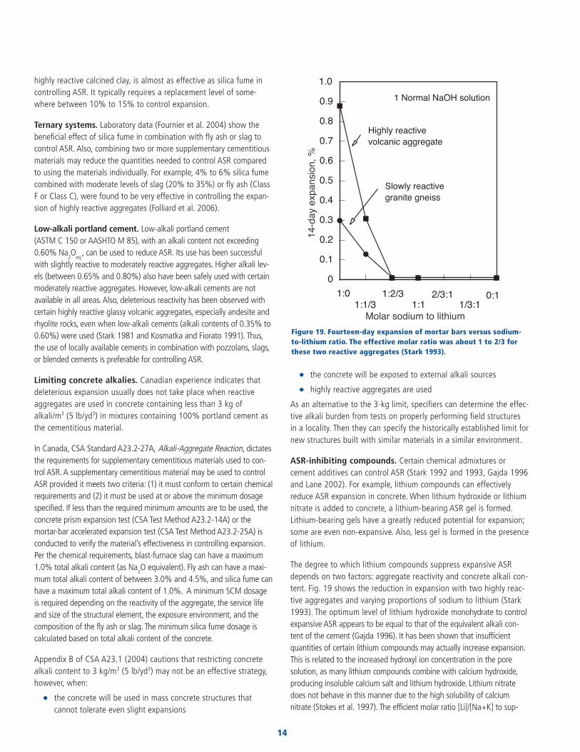
ASR-inhibiting compounds. Certain chemical admixtures orcement additives can control ASR (Stark 1992 and 1993, Gajda 1996and Lane 2002). For example, lithium compounds can effectivelyreduce ASR expansion in concrete. When lithium hydroxide or lithiumnitrate is added to concrete, a lithium-bearing ASR gel is formed.Lithium-bearing gels have a greatly reduced potential for expansion;some are even non-expansive. Also, less gel is formed in the presenceof lithium.
The degree to which lithium compounds suppress expansive ASRdepends on two factors: aggregate reactivity and concrete alkali con-tent. Fig. 19 shows the reduction in expansion with two highly reac-tive aggregates and varying proportions of sodium to lithium (Stark1993). The optimum level of lithium hydroxide monohydrate to controlexpansive ASR appears to be equal to that of the equivalent alkali con-tent of the cement (Gajda 1996). It has been shown that insufficientquantities of certain lithium compounds may actually increase expansion.This is related to the increased hydroxyl ion concentration in the poresolution, as many lithium compounds combine with calcium hydroxide,producing insoluble calcium salt and lithium hydroxide. Lithium nitratedoes not behave in this manner due to the high solubility of calciumnitrate (Stokes et al. 1997). The efficient molar ratio [Li]/[Na+K] to sup-
14
B
B
B B B
J
J
J J J0
0.1
0.2
0.3
0.4
0.5
0.6
0.7
0.8
0.9
1.0
14-d
ayex
pans
ion,
%Molar sodium to lithium
1 Normal NaOH solution
Highly reactivevolcanic aggregate
Slowly reactivegranite gneiss
1:01:1/3
1:2/31:1
2/3:11/3:1
0:1
Figure 19. Fourteen-day expansion of mortar bars versus sodium-to-lithium ratio. The effective molar ratio was about 1 to 2/3 forthese two reactive aggregates (Stark 1993).

press expansion may vary from as low as 0.56 to over 1.11 depending onthe aggregate source. The Federal Highway Administration (FHWA) haspublished Interim Recommendations for the Use of Lithium to Mitigate orPrevent Alkali-Silica Reaction (ASR) (Folliard et al. 2006), which providesinformation and guidance to test, specify, and use lithium compounds innew concrete construction.
Neither ASTM C 1260 (AASHTO T 303) nor ASTM C 1567 should beused to test the effectiveness of lithium compounds. ASTM C 1293, witha test duration of two years, should be used to assess lithium com-pounds (Folliard et al. 2006).
Aggregate selection and beneficiation. Using a nonreactive aggre-gate is ideal but not always practical. The surest way of predicting aggre-gate performance is a good service record, but this information is notalways available. Instead, it is frequently necessary to investigate aggregatequality through the tests that measure potential reactivity.
It may be possible to improve aggregate quality by selective processingknown as beneficiation. Processes that have been used are heavy mediaseparation, jigging, rising-current classification, and crushing. In some cases,one of these steps may be able to remove a large portion of the reactiveaggregate, but also may remove some of the good aggregate.
It may be possible to blend reactive aggregate with nonreactiveaggregate to mitigate the effects of ASR. This blending sometimesoccurs as part of the quarrying process, when only small amounts ofreactive aggregate are present. Nonreactive aggregates can be pur-posefully blended with known reactive aggregates. In some cases,this means of diluting aggregates can adequately control expansiveASR. An example of this method is limestone sweetening.
Limestone sweetening, or replacing up to 30% of a reactive sand-gravelaggregate with crushed limestone, is effective in preventing deterioration insome sand-gravel aggregate concretes. The resulting combination of materi-als should be tested in accordance with ASTM C 227,ASTM C 1260(AASHTO T 303),ASTM C 1567, or ASTM C 1293 to verify control of delete-rious expansion.
Controlling Existing ASRLithium salts have also been applied topically to treat ASR in existing concrete. Laboratory studies show that treating small samples with lithi-um can reduce expansion (Stokes et al. 2000). In the field however,lithium may not penetrate sufficiently into the structure to mitigate thereaction below the surface, allowing continuous deterioration (Folliard etal. 2006). Tuan (2005) found that insufficient amounts of lithium penetra-tion into hardened concrete may even enhance ASR expansion. Methodsof driving lithium ions into the concrete using electrical fields or vacuumimpregnation are being studied to improve penetration. FHWA (2006aand 2006b) has published guidance for selecting ASR-affected structuresfor lithium treatment. They identify ideal structures for lithium treatmentas those for which, (1) ASR has been confirmed as the principal cause fordeterioration; (2) the deterioration has reached a certain severity, and (3) laboratory testing or in-situ monitoring indicates a potential for signifi-cant further expansion if the structure is left untreated.
Recycled Concrete as Aggregate
When recycled concrete is used as coarse aggregate in new concrete, itshould be evaluated in the same manner as virgin aggregate (see Fig.13).
Recycling concrete for use as coarse aggregate in new constructioncan be economical, saving disposal costs of old concrete and reduc-ing the need for virgin aggregate. Increased environmental concernsand diminishing quarry resources may make recycling even more pop-ular in the future (ACPA 1993 and ECCO 1999).
There are two main uses for recycled aggregate in new pavementconstruction: as a granular subbase material and as coarse aggregatefor the new concrete pavement.
Research was undertaken to study expansion of new concrete madewith recycled ASR-affected concrete as aggregate (Stark 1996). Itwas determined that potential for ASR in the new concrete is affectedby the old concrete’s original alkali level, extent of expansion, andthe remaining potential reactivity of the aggregate. Also, the alkalicontent of new concrete had a significant effect on subsequentexpansions due to ASR. The use of a low-lime Class F fly ash greatlyreduced expansions due to ASR in new concrete.
The research demonstrated that with appropriate selection of cemen-titious materials, even recycled concrete containing highly reactiveaggregate can be used safely. The engineer must know the ASRpotential of the recycled aggregate. If information is not availableabout the cementitious materials and aggregates contained in theold concrete, even if the old concrete has not experienced ASR deteri-oration, its ASR potential should be petrographically evaluated priorto recycling. Laboratory expansion tests may also be helpful.
Alkali-Carbonate Reaction
MECHANISM OF ACR Reactions observed with certain dolomitic rocks are associated withalkali-carbonate reaction (ACR). Reactive rocks usually contain larger
15
Diagnosis and Control of Alkali-Aggregate Reactions in Concrete
Calcitegrains
Networkof clay
Channel formigration ofwater and ions(K+ and OH+) Mg(OH)2
K2CO3
CaCO3
Ratio Ca/Mgreducedgradually
Matrix
Originalsample
KOHsolution
Immersed inalkali solution
Expansionand cracking
Dolomitecrystal
Reactivecarbonaterock
Figure 20. Schematic diagram of the mechanism of alkali-carbonate reac-tion. A dolomite crystal combines with alkalies in solution to formbrucite, and potassium and calcium carbonates (Tang, Liu, and Han 1987).

crystals of dolomite scattered in and surrounded by a fine-grainedmatrix of calcite and clay. Calcite is one of the mineral forms of calci-um carbonate; dolomite is the common name for calcium-magnesiumcarbonate. ACR is relatively rare because aggregates susceptible tothis reaction are usually unsuitable for use in concrete for other rea-sons—strength potential, etc.
Argillaceous dolomitic limestone contains calcite and dolomite withappreciable amounts of clay and can contain small amounts of reactive silica. Alkali reactivity of carbonate rocks is not usuallydependent on clay mineral composition (Hadley 1961). Aggregateshave potential for expansive ACR if the following lithological charac-teristics exist (Ozol 2006 and Swenson and Gillott 1967):
• clay content, or insoluble residue content, in the range of 5% to 25%
• dolomite content (percentage in carbonate fraction) in the range of40% to 60%
• interlocking dolomite grains (late expansion)
• small size (25 to 30 µm) , discrete dolomite crystals (rhombs)suspended in a clay matrix
DedolomitizationDedolomitization, or the breaking down of dolomite, is normally associat-ed with expansive ACR (Hadley 1961). Concrete that contains dolomiteand has expanded also contains brucite (magnesium hydroxide,Mg(OH)
2), which is formed by dedolomitization. Dedolomitization pro-
ceeds according to the following equation (Hadley 1961):
CaMg(CO3)2
(dolomite) + 2MOH (alkali hydroxide solution)pMg(OH)
2(brucite) + CaCO
3(calcium carbonate) + M
2CO
3(alkali
carbonate)
where M represents an alkali element, such as potassium, sodium, orlithium.
Fig. 20 illustrates this process. Expansion may be due to a combina-tion of migration of alkali ions and water molecules into the restrict-ed space of the fine-grained matrix surrounding the dolomite rhomb,migration of these materials into the rhomb, and the growth andrearrangement of the dedolomitization products, especially brucite,which exerts pressures as it crystallizes (Tang, Liu, and Han 1987).
The dedolomitization reaction and subsequent crystallization ofbrucite may cause considerable expansion. Whether dedolomitizationcauses expansion directly or indirectly, it’s usually a prerequisite toother expansive processes (Tang, Deng, and Lon 1994). In one inves-tigation of pavement deterioration, dolomite did not appear to bealtered, as no brucite was found. Cracking was due to expansiveforces arising from a chemical reaction and expansion of the clayminerals in the aggregate matrix (Wong 1996).
Other Factors The nominal maximum size of the reactive aggregate influences theamount and extent of reaction.Testing done with a particular ACR rock andhigh-alkali cement showed that both the rate and degree of expansiondecreased with a decrease in nominal maximum aggregate size (Swenson
and Gillot 1960). Concrete can contain a certain percentage of carbonatereactive aggregates without experiencing detrimental expansion.
Alkali-carbonate reaction is also affected by pore solution alkalinity.ACR can occur in a solution with a relatively low pH. As the pH ofthe pore solution increases, potential for the alkali-carbonate reac-tion increases. During ACR, calcium hydroxide produced by portlandcement hydration can combine with the alkali carbonate produced inthe initial reaction (see equation above) to regenerate alkali hydrox-ide and calcium carbonate. This reaction not only regenerates alkali,but also reduces the concentration of carbonate ions and aggravatesthe dedolomitization reaction. Low-alkali cements and supplemen-tary cementitious materials—even at high levels—are thus ineffec-tive at reducing ACR to acceptable limits (Tang, Deng, and Lon 1994).
Visual Symptons of Expansive ACR
ACR, like ASR, is a chemical process that can induce physical dam-age—expansion and cracking of concrete (Fig. 21). Informationobtained from a site inspection should be evaluated along with test-ing to determine the destructive mechanism.
ACR-affected concrete does not exhibit telltale features to distinctlyidentify alkali-carbonate reaction as the cause of cracking. The crackpattern will be influenced by restraint conditions and moisture avail-ability. In slabs, decks, and footings, when a top-to-bottom or side-to-side moisture gradient exists, map cracking is likely to occur. Thisgrowth can cause closed joints, misalignment of adjoining members,crushed concrete, and pavement blowups (Ozol 2006). Because lowlevels of alkali can initiate ACR and higher levels can exacerbate it,the use of deicer salts that contain alkalies can increase damage.
Test Methods for Identifying ACR Distress
Brucite is usually formed during destructive ACR and is evident inexpanded concrete. Its presence must be determined through petro-
16
Figure 21. Map cracking pattern caused by ACR (IMG12982).

graphic or other analysis. The concrete and carbonate rocks must beexamined petrographically in accordance with ASTM C 856 and C 295 respectively. Physical expansion tests, such as ASTM C 586,performed in a laboratory are also helpful to verify the presence of ACR.
Test Methods for Identifying Potentially Reactive Aggregate
ACR is rather uncommon because the carbonate rocks containingproportions of dolomite, calcite, and insoluble material that will leadto dedolomitization do not often compose a major portion of theaggregate supply (Mather 1975). The three tests commonly used toidentify potentially alkali-carbonate reactive aggregate are describedbelow and in Table 2 at the end of this document.
Petrographic Examination (ASTM C 295) Petrographic examination, ASTM C 295, can be used to establish thecharacter of rock. Potentially alkali-carbonate reactive aggregateshave a characteristic lithology that makes them easy to identify. Therock is considered to be reactive if the physical make-up is a fine-grained matrix of calcite and clay surrounding rhombic crystals ofdolomite. With no known exceptions, all rocks with the characteristiclithology have expanded in an alkaline environment, and all rocks in con-crete that have expanded due to ACR exhibit the characteristic lithology(Ozol 2006). Petrographic testing identifies ACR-susceptible rocks.
Rock Cylinder Method (ASTM C 586) ASTM C 586, Test Method for Potential Alkali Reactivity ofCarbonate Rocks for Concrete Aggregates (Rock Cylinder Method),can determine the expansive characteristics of carbonate rocks. Asmall rock cylinder 35 mm long by 9 mm dia. (1.38 in. x 0.35 in.) isimmersed in an alkaline (1 N NaOH) solution at room temperature.Length change of the specimen may be monitored for up to or over ayear, but expansive tendencies are usually evident after about 1month. A 28-day expansion of 0.10% or more indicates potential fordeleterious expansion in a service environment.
This test procedure has a few disadvantages. Obtaining a representa-tive sample may be difficult and test duration may be long. Furthermore,this test is intended only as a supplement to other test procedures.Expansive behavior of aggregate can be predicted by the rock cylinder method. But since expansion of concrete depends on othervariables that include water-cement ratio, water-soluble alkalies, andthe paste-to-aggregate ratio, ASTM C 586 alone should not be usedas an acceptance test for aggregate (Ozol 2006).
Concrete Prism Tests (ASTM C 1105 and CSA A23.2-14A) ASTM C 1105, Test Method for Length Change of Concrete Due toAlkali-Carbonate Rock Reaction, is best used to verify potential reactiv-ity of an aggregate that is known to contain ACR-susceptible rock. Sixconcrete prism specimens are fabricated with the aggregate in ques-tion and the job cement. If the job cement is not known, a Type I orType II cement conforming to ASTM C 150 (AASHTO M 85) should beused. The test should preferably run for one year, but 3 or 6 monthscan be used if longer test times are not feasible. An expansion equal to
or more than 0.03% at one year, 0.025% at 6 months, or 0.015% at 3 months indicates potentially deleterious aggregate (ASTM C 1105,Appendix).
This test makes it possible to measure expansive tendencies ofcement-aggregate combinations rather than expansive characteristicsof the rock alone, but the year-long test duration is a drawback. Ifthis test has been performed on a cement-aggregate combinationinvolving an aggregate that has not been examined petrographicallyusing C 295, or has not been measured by the rock prism expansiontest (C 586), one or both of those tests should also be performed.
The Canadian Standards Association CSA A23.2-14A, PotentialExpansivity of Aggregates (Procedure for Length Change Due toAlkali-Aggregate Reaction in Concrete Prisms), is similar to C 1105,as both tests require similar specimens and storage conditions.Cement alkali levels, aggregate gradation, and limits that indicateexpansive behavior differ slightly for the two methods. The Canadianversion of the test stipulates the cement alkali level to be used, mak-ing the test more standardized and allowing comparison among testresults. The higher cement alkali content in A23.2-14A makes it amore aggressive test than C 1105, so it should identify potentiallyreactive rocks that might pass C 1105.
Control of Alkali-Carbonate Reaction
ACR-susceptible aggregate has a specific composition that is readilyidentified by petrographic testing. If a rock indicates ACR-susceptibility,preventive measures must be taken. It’s difficult to arrest alkali-car-bonate reaction once expansion has begun.
Selective QuarryingQuarries are routinely mapped and tested to define the rock group-ings and stratification. Reactive rock may be naturally isolated in layers or by other physical features. In this case, selective quarryingcan be used to completely avoid the reactive strata. Small portions ofreactive aggregate may become naturally diluted when the rock isprocessed.
Blended Aggregate Another option is blending reactive aggregate with aggregate provenby testing—and service record, if possible—to be nonreactive. Thiscan mitigate the reactive aggregate’s detrimental effects on concrete.Accordingly, the Appendix in ASTM C 1105 limits the safe proportionof reactive aggregate to 20% for either the coarse or fine sizes whenused alone, or a limit of 15% total when used in combination. Testthe resulting diluted or blended aggregate using ASTM C 1105 to becertain it is acceptable for use in portland cement concrete.
Aggregate Size Limiting the nominal maximum size of aggregate is another way tominimize expansion due to ACR. Use the smallest practical nominalmaximum size of aggregate to minimize detrimental expansion(Swenson and Gillott 1967).
17
Diagnosis and Control of Alkali-Aggregate Reactions in Concrete

Low-Alkali CementLow-alkali cement is not generally effective in controlling expansiveACR. Even cements with alkali levels as low as 0.40% can producepore solutions with sufficient alkalinity to initiate reaction. Due to thechemistry of the alkali-carbonate reactions, alkalies are regeneratedrather than consumed. They undergo a series of reactions with aggre-gates and are then available to react again with more aggregate(Hadley 1961). The cement alkali level is of less concern than thealkali content of concrete, which should be kept as low as possiblewhen using alkali-carbonate reactive aggregate.
PozzolansSupplementary cementitious materials are not very effective in controllingACR. Pozzolans tie up alkalies by reacting with them, but ACR can be ini-tiated with low levels of alkali, and pozzolans may not consume enoughalkalies to limit the reaction. Pozzolans do reduce paste porosity, whichhelps limit the moisture available for reaction. The reduced concreteporosity is beneficial, but concrete in most environments contains enoughmoisture to sustain alkali-carbonate reaction. Larger amounts of poz-zolans could possibly control ACR, but these amounts are generally toohigh to be practical. ACR is more effectively controlled by processing theaggregate to minimize particle size or the amount of reactive aggregatein the concrete.
ACR-Inhibiting CompoundsWhile some researchers have found that lithium compounds appearto control ACR (Gajda 1996), others found that lithium hydroxideand lithium carbonate increase expansion of alkali-carbonate reactiverock (Wang, Tysl, and Gillott 1994).
Common Questions about AAR
Q: If an aggregate has good field performance, why test the aggre-gate for deleterious behavior?
A: This requires a two-part answer. Field history is a valuable source ofinformation that indicates an aggregate’s behavior in service. If condi-tions of service and the ingredients, including total alkali content of theconcrete, are the same in the existing and proposed concrete structures,there is no need to test an aggregate that has a good record of service.If, however, the aggregate varies significantly within the quarry, or ifexposure conditions of the proposed structure will be more severe thanin structures exhibiting good performance, or if the concrete ingredientsare significantly different, the aggregate should be tested.
Q: If an aggregate passes ASTM C 1260 (AASHTO T 303) and otherASR requirements, should there be restrictions on cementitious mate-rials, such as limits on cement alkalies?
A: No. Nonreactive aggregate can be used without undue restrictionson cementitious materials.
Q: Should an aggregate be eliminated from use if it fails ASTM C 1260(AASHTO T 303) or other ASR tests?
A: No. First, deleterious behavior must be confirmed by field history orASTM C 1293 before an aggregate is classified as potentially reactive.Even then, aggregates that are classified as potentially reactive can besafely used with pozzolans, slags, or ASR-inhibiting compounds, blend-ed cements, or by limiting the total alkali content of the concrete.Another option would be to blend the aggregate with a nonreactiveaggregate to a level that is not harmfully reactive.
Q: Is it possible for ASTM C 1260 (AASHTO T 303) to give a false negative?A false positive?
A:Yes to each. False negatives, where a reactive aggregate is identified asnonreactive, are not common with ASTM C 1260 (AASHTO T 303).Most reactive aggregates will be identified by this test because it is sosevere. False positives, where a nonreactive aggregate is identified asbeing reactive, are more common, again because the test method is sosevere. The alkali hydroxide concentration of most field concretes ismuch lower than that of the test method and is at a level that doesnot induce harmful reactivity for many aggregates that fail C 1260 (AASHTO T 303). It cannot be stressed enough that supple-mental information should be developed to evaluate an aggregate.
Q: If a pozzolan is required in a given concrete mixture, should theaggregate be tested alone to determine its potential for ASR? Shouldall of ASTM tests C 227, C 289, C 295, C 1260 (AASHTO T 303),C 1293, and C 1567 be performed?
A: If the concrete is required to contain a pozzolan anyway, consider usingASTM C 1567 to investigate expansive tendencies of the combination ofaggregates and cementitious materials. Note that some pozzolans at somedosages can increase ASR potential, so the mixture design should be strictlydefined and adhered to in order for the combination of materials to workeffectively. It is not necessary to require every test to prove effectivenessand it’s not very efficient. Choose one test, such as C 1567, that uses theproposed cementitious materials to evaluate their effectiveness at control-ling expansion. If one or two years are available, C 227 or C 1293 can beperformed using the pozzolan.
Q: Isn’t the easiest way to control ASR to avoid using potentiallyreactive aggregate and require use of a low-alkali cement?
A: Though this can effectively control ASR, it would not be efficient.Not all geographical areas have nonreactive aggregates or low-alkalicements. Requiring these materials would probably result in extracosts and lost time. Concrete mixtures should be designed to be eco-nomical in addition to being safe from ASR potential. Local materialsusually provide the greatest availability and best economy.
Q: Are all fly ashes and slags equal at controlling expansion from ASR,and is there one single dosage that will always be effective?
A: All fly ashes and slags are not equal at controlling expansion due toASR. Class F ashes (typically low CaO) as a group are usually more effec-tive than Class C ashes. And within a group, one ash can be more effec-tive than another. Slags are generally less variable in composition than flyashes due to their origin. Also, aggregates of different degrees of
18

reactivity and different cement alkali levels require different dosages of flyash or slag. Since no one dosage is effective with all fly ashes or slags, itis necessary to investigate any fly ash’s or slag’s ability to control ASR bytesting. Concurrent testing of various dosages helps determine the appro-priate fly ash dosage. Use ASTM C 1293 or ASTM C 1567.
Q: Can I use ASTM C 1260 (AASHTO T 303) or ASTM C 1567 to testthe effectiveness of a portland cement to control ASR?
A: No. The standard tests as written are not designed to test theeffect of different portland cements on ASR. The test specimen alkalicontent rises to approach that of the solution in which it is sub-merged, regardless of the original alkali content of the cement.
Q: A pavement engineer wants to replace some of the cement in astandard mixture with fly ash to control ASR but is concerned aboutpoor strength gain in cold weather. Any solutions?
A: Yes. Use the fly ash as an addition or partial replacement to thestandard mixture instead of replacing the cement. The fly ash will stillcontrol ASR, and the mix will gain strength in cold weather similar tothat of the cement-only mixture. Chemical admixtures or Type IIIcement can also be used to accelerate strength gain.
Related Publications
The publications cited in this text, as well as other related publica-tions, are available from Portland Cement Association.The following are particularly useful:
• Guide Specification for Concrete Subject to Alkali-SilicaReactions (IS415)
• Alkali-Silica Reactivity: An Overview of Research (LT177)
• Handbook for the Identification of Alkali-Silica Reactivity(LT165)
• “Detecting and Avoiding Alkali-Aggregate Reactivity,” ConcreteTechnology Today (PL913)(http://www.cement.org/pdf_files/pl913.pdf)
• “Cornell’s Gel Fluorescence Test Identifies ASR Products inConcrete,” Concrete Technology Today (PL922)(http://www.cement.org/pdf_files/pl922.pdf)
• “Lithium-Based Admixtures—An Alternative for Preventing ExpansiveAlkali-Silica Reaction,” Concrete Technology Today (PL931)(http://www.cement.org/pdf_files/pl931.pdf)
• Design and Control of Concrete Mixtures (EB001)
• Alkali-Silica Reactivity: Some Reconsiderations (RD076)
• Lithium Salt Admixture—An Alternative Method to PreventExpansive Alkali-Silica Reactivity (RP307)
• Field and Laboratory Studies on the Reactivity of Sand-GravelAggregates (RX221)
• The Use of Recycled-Concrete Aggregate from ConcreteExhibiting Alkali-Silica Reactivity (RD114)
19
Diagnosis and Control of Alkali-Aggregate Reactions in Concrete
• Development of a Cement to Inhibit Alkali-Silica Reactivity(RD115)
• “Developments in Alkali-Silica Gel Detection,” ConcreteTechnology Today (PL991)(http://www.cement.org/pdf_files/pl991.pdf)
• Substitution of Fly Ash for Cement or Aggregate in Concrete:Strength Development and Suppression of ASR (RD127)
• Surface Popouts Caused by Alkali-Aggregate Reaction (RD121)
To order by Web site, mail, phone, or fax:
Customer ServicePortland Cement Association5420 Old Orchard RoadSkokie, IL 60077-1083Phone: 800.868.6733Fax : 847.966.9666Web site: www.cement.org/bookstore

Test
nam
ePu
rpo
seTy
pe o
f te
stTy
pe o
f sa
mp
leD
ura
tio
n o
f te
stM
easu
rem
en
tC
rite
ria
Co
mm
en
ts
Pote
ntia
l Alk
ali
To t
est
the
susc
eptib
ility
of
Mor
tar
bars
sto
red
over
At
leas
t 4
mor
tar
bars
;Va
ries:
first
Leng
th c
hang
ePe
r A
STM
C 3
3, m
axim
um 0
.10%
Test
may
not
pro
duce
sig
nific
ant
Reac
tivity
of
Cem
ent-
cem
ent-
aggr
egat
ew
ater
at
37.8
°C (1
00°F
)st
anda
rd d
imen
sions
:m
easu
rem
ent
at 1
4 da
ysex
pans
ion
at 6
mon
ths,
or if
not
expa
nsio
n, e
spec
ially
for
car
bona
teA
ggre
gate
co
mbi
natio
ns t
o ex
pans
ive
and
high
rel
ativ
e25
x25x
285
mm
then
1, 2
, 3, 4
, 5, 6
, 9, a
ndav
aila
ble
for a
6-m
onth
per
iod
aggr
egat
e Co
mbi
natio
nsre
actio
ns in
volv
ing
alka
lies
hum
idity
(1x1
x111 / 4 i
n.)
12 m
onth
s and
eve
ry 6
max
imum
of 0
.05%
at 3
mon
ths
Long
test
dur
atio
n(M
orta
r-Bar
Met
hod)
mon
ths a
fter
that
as
Expa
nsio
ns m
ay n
ot b
e fr
om A
AR
(AST
M C
227
)ne
cess
ary
Pote
ntia
l Alk
ali
To te
st th
e po
tent
ial f
orIm
mer
sion
of m
orta
rA
t lea
st 3
mor
tar b
ars
16 d
ays
Leng
th c
hang
eIf
grea
ter t
han
0.10
%, g
o to
Very
fast
alte
rnat
ive
to C
227
Reac
tivity
of A
ggre
gate
sde
lete
rious
alk
ali-s
ilica
bars
in a
lkal
ine
solu
tion
supp
lem
enta
ry te
st p
roce
dure
s; if
Use
ful f
or sl
owly
reac
ting
aggr
egat
es(M
orta
r-Bar
Met
hod)
reac
tion
of a
ggre
gate
inat
80°
C (1
76°F
)gr
eate
r tha
n 0.
20%
, ind
icat
ive
ofor
one
s tha
t pro
duce
exp
ansio
n(A
STM
C 1
260/
mor
tar b
ars
pote
ntia
lly d
elet
erio
us e
xpan
sion
late
in th
e re
actio
nA
ASH
TO T
303
)
Pote
ntia
l Alk
ali-S
ilica
To d
eter
min
e po
tent
ial
Sam
ple
reac
ted
with
3-25
gra
m sa
mpl
es o
f24
hou
rsD
rop
in a
lkal
inity
and
Poin
t plo
tted
on
grap
h fa
lls in
Qui
ck re
sults
Reac
tivity
of A
ggre
gate
s re
activ
ity o
f sili
ceou
sal
kalin
e so
lutio
n at
80°
Ccr
ushe
d an
d sie
ved
amou
nt o
f sili
cade
lete
rious
or p
oten
tially
So
me
aggr
egat
es g
ive
low
(Che
mic
al M
etho
d)ag
greg
ates
(176
°F)
aggr
egat
eso
lubi
lized
dele
terio
us a
rea
expa
nsio
ns e
ven
thou
gh th
ey h
ave
(AST
M C
289
)hi
gh si
lica
cont
ent—
Not
relia
ble
Det
erm
inat
ion
ofTo
det
erm
ine
the
pote
ntia
lCo
ncre
te p
rism
s sto
red
3 pr
isms p
er c
emen
t-Va
ries:
first
mea
sure
men
tLe
ngth
cha
nge
Per A
ppen
dix
XI, p
oten
tially
Pref
erre
d m
etho
d of
ass
essm
ent
Leng
th C
hang
e of
ASR
exp
ansio
n of
cem
ent-
over
wat
er a
t 38°
Cag
greg
ate
com
bina
tion,
at 7
day
s, th
en 2
8 an
dde
lete
rious
ly re
activ
e if
expa
nsio
nBe
st re
pres
ents
the
field
Conc
rete
Due
toag
greg
ate
com
bina
tions
(100
.4°F
)st
anda
rd d
imen
sions
:56
day
s, th
en 3
, 6, 9
, and
equa
ls or
exc
eeds
0.0
4% a
t 1 y
ear
Long
test
dur
atio
n fo
r mea
ning
ful r
esul
tsA
lkal
i-Sili
ca R
eact
ion
75x7
5x28
5mm
12 m
onth
s and
eve
ry(o
r 0.0
4% a
t 2 y
ears
if S
CMs a
re to
Use
as a
supp
lem
ent t
o C
227,
(Con
cret
e Pr
ism T
est)
(3X3
X111 / 4 i
n.)
6 m
onth
s aft
er th
at a
sbe
eva
luat
ed)
C 29
5, C
289
, C 1
260,
and
C 1
567
(AST
M C
129
3)ne
cess
ary
Sim
ilar t
o CS
A A
23.2
-14A
Pote
ntia
l Vol
ume
To d
eter
min
e th
e po
tent
ial
Mor
tar b
ars s
tore
d in
3 m
orta
r bar
s per
52 w
eeks
Leng
th c
hang
ePe
r AST
M C
33,
uns
atisf
acto
ryPr
imar
ily u
sed
for a
ggre
gate
sCh
ange
of C
emen
t-A
SR e
xpan
sion
of c
emen
t-w
ater
at 2
3°C
(73.
4°F)
cem
ent-
aggr
egat
eag
greg
ate
if ex
pans
ion
equa
ls or
from
Okl
ahom
a, K
ansa
s,A
ggre
gate
aggr
egat
e co
mbi
natio
nsco
mbi
natio
n, st
anda
rdex
ceed
s 0.2
00%
at 1
yea
rN
ebra
ska,
and
Iow
aCo
mbi
natio
nsdi
men
sions
25x
25x2
85m
m(A
STM
C 3
42)
(1x1
x111 / 4 i
n.)
Effe
ctiv
enes
s of
To d
eter
min
e ef
fect
iven
ess
Mor
tar b
ars—
usin
g Py
rex
At l
east
3 m
orta
r bar
sVa
ries:
first
Leng
th c
hang
ePe
r AST
M C
989
, min
imum
75%
Hig
hly
reac
tive
artif
icia
lPo
zzol
ans o
r GBF
S in
of p
ozzo
lans
or
glas
s as a
ggre
gate
—an
d al
so 3
mor
tar b
ars o
fm
easu
rem
ent a
t 14
days
,re
duct
ion
in e
xpan
sion
or 0
.020
%ag
greg
ate
may
not
repr
esen
tPr
even
ting
Exce
ssiv
esla
g in
con
trol
ling
stor
ed o
ver w
ater
at
cont
rol m
ixtu
reth
en 1
, 2, 3
, 4, 6
, 9, a
nd 1
2m
axim
um e
xpan
sion
or p
er C
618
,re
al a
ggre
gate
con
ditio
nsEx
pans
ion
of C
oncr
ete
expa
nsio
n fr
om A
SR37
.8°C
(100
°F) a
nd h
igh
mon
ths a
nd e
very
6
com
paris
on a
gain
st lo
w-a
lkal
iPy
rex
cont
ains
alk
alie
sD
ue to
the
Alk
ali-S
ilica
rela
tive
hum
idity
mon
ths a
fter
that
as
cont
rol
Reac
tion
nece
ssar
y(A
STM
C 4
41)
Cons
titue
nts o
fTo
giv
e de
scrip
tive
nom
en-
Visu
al Id
entif
icat
ion
Varie
s, bu
t sho
uld
beSh
ort d
urat
ion—
as lo
ngD
escr
iptio
n of
type
and
Not
app
licab
leTh
ese
desc
riptio
ns a
re u
sed
toN
atur
al M
iner
alcl
atur
e fo
r the
mor
e co
mm
onre
pres
enta
tive
of e
ntire
as it
take
s to
visu
ally
prop
ortio
n of
min
eral
sch
arac
teriz
e na
tura
lly-o
ccur
ing
Agg
rega
tes
or im
port
ant n
atur
also
urce
exam
ine
the
sam
ple
in a
ggre
gate
min
eral
s tha
t mak
e up
com
mon
(AST
M C
294
)m
iner
als—
a go
od st
artin
gag
greg
ate
sour
ces
poin
t to
pred
ict b
ehav
ior
Petr
ogra
phic
To e
valu
ate
poss
ible
agg
rega
teVi
sual
and
micr
osco
pic
Varie
s with
kno
wle
dge
ofSh
ort d
urat
ion—
visu
alPa
rticl
e ch
arac
teria
stics
,N
ot a
pplic
able
Usu
ally
inclu
des o
ptica
lEx
amin
atio
n of
reac
tivity
thro
ugh
petr
ogra
phic
exam
inat
ion
of p
repa
red
quar
ry: c
ores
53
to 1
00m
mex
amin
atio
n do
es n
otlik
e sh
ape,
size
, tex
ture
,m
icros
copy
; may
inclu
de X
RDA
ggre
gate
s for
exam
inat
ion
sam
ples
—sie
ve a
naly
sisin
dia
met
er (2
1 / 8to
4 in
.),in
volv
e lo
ng te
st p
erio
dsco
lor,
min
eral
com
posit
ion,
anal
ysis,
diff
eren
tial t
herm
alCo
ncre
tem
icros
copy
, scr
atch
or
45 k
g (1
00 lb
) or 3
00 p
iece
s,ph
ysica
l con
ditio
nan
alys
is, o
r inf
rare
d sp
ectr
osco
py—
(AST
M C
295
)ac
id te
sts
or 2
kg
(4 lb
)se
e C
294
for d
escr
iptiv
e no
men
clatu
re
Petr
ogra
phic
To o
utlin
e pe
trog
raph
icVi
sual
(unm
agni
fied)
At l
east
one
core
150
mm
Shor
t dur
atio
n—in
clude
sIs
the
aggr
egat
e kn
own
See
mea
sure
men
t—th
is ex
amin
atio
nSp
ecim
ens c
an b
e ex
amin
ed w
ithEx
amin
atio
n of
exam
inat
ion
proc
edur
es o
fan
d m
icros
copi
cdi
amet
er b
y 30
0 m
m lo
ngpr
epar
atio
n of
sam
ples
to b
e re
activ
e?de
term
ines
if A
SR re
actio
ns h
ave
ster
eom
icros
cope
s, po
lariz
ing
Har
dene
d Co
ncre
teha
rden
ed co
ncre
te—
usef
ul in
exam
inat
ion
of p
repa
red
(6 in
. dia
met
er b
y 12
in.
and
visu
al a
nd m
icros
copi
cO
rient
atio
n an
dta
ken
plac
e an
d th
eir e
ffec
ts u
pon
micr
osco
pes,
met
allo
grap
hic
(AST
M C
856
/de
term
inin
g co
nditi
on o
rsa
mpl
eslo
ng)
exam
inat
ion
geom
etry
of c
rack
sth
e co
ncre
tem
icro
scop
es, a
nd S
EMA
ASH
TO T
299
)pe
rfor
man
ceIs
ther
e an
y ge
l pre
sent
?U
sed
in c
onju
nctio
n w
ith o
ther
test
s
Ura
nyl-A
ceta
teTo
iden
tify
prod
ucts
of A
SRSt
aini
ng o
f a fr
eshl
yVa
ries:
core
, lap
ped
Imm
edia
te re
sults
Inte
nsity
of f
luor
esce
nce
Lack
of f
luor
esce
nce
Iden
tifie
s sm
all a
mou
nts o
f ASR
Trea
tmen
t Pro
cedu
rein
har
dene
d co
ncre
teex
pose
d co
ncre
tesu
rfac
e, b
roke
n su
rfac
ege
l whe
ther
they
cau
se(A
STM
C 8
56 A
nnex
)su
rfac
e an
d vi
ewin
gex
pans
ion
or n
otun
der U
V lig
htO
pal,
a na
tura
l agg
rega
te, a
ndca
rbon
ated
pas
te c
an g
low
—in
terp
ret r
esul
ts a
ccor
ding
lyT e
xt m
ust b
e su
pple
men
ted
bype
trog
raph
ic ex
amin
atio
n an
d ph
ysica
lte
sts f
or d
eter
min
ing
conc
rete
exp
ansio
n
Pote
ntia
l Alk
ali-S
ilica
To te
st th
e po
tent
ial f
orIm
mer
sion
of m
orta
rA
t lea
st 3
mor
tar b
ars
16 d
ays
Leng
th ch
ange
If gr
eate
r tha
n 0.
10%
, ind
icativ
e of
Very
fast
alte
rnat
ive
to C
129
3Re
activ
ity o
f Com
bina
tions
dele
terio
us a
lkal
i-sili
caba
rs in
alk
alin
e so
lutio
nfo
r eac
h ce
men
titio
uspo
tent
ial d
elet
erio
us e
xpan
sion;
use
Allo
ws f
or e
valu
atio
n of
supp
lem
enta
ryof
Cem
entit
ious
Mat
eria
lsre
actio
n of
cem
entit
ious
at 8
0°C
(176
°F)
mat
eria
ls an
d ag
greg
ate
C 12
93 (2
-yea
r tes
t) to
conf
irmce
men
ting
mat
eria
ls an
d de
term
inat
ion
and
Agg
rega
tem
ater
ials
and
aggr
egat
eco
mbi
natio
nof
opt
imum
dos
age
(Acc
eler
ated
Mor
tar-B
arco
mbi
natio
ns in
mor
tar b
ars
Met
hod)
bars
(AST
M C
156
7)
20
Tabl
e 1.
Test
Met
hods
for A
lkal
i-Si
lica
Reac
tivity

Test
nam
ePu
rpo
seTy
pe o
f te
stTy
pe o
f sa
mp
leD
ura
tio
n o
f te
stM
easu
rem
en
tC
rite
ria
Co
mm
en
ts
Pote
ntia
l Alk
ali
To d
eter
min
e th
e ex
pans
ive
Imm
ersio
n of
roc
kO
ne r
ock
cylin
der,
35 m
mU
p to
or
over
1 y
ear,
but
Leng
th c
hang
eN
ot a
pplic
able
Secu
ring
repr
esen
tativ
e sa
mpl
eRe
activ
ity o
f Ca
rbon
ate
char
acte
ristic
s of
car
bona
tecy
linde
rs in
alk
alin
elo
ng a
nd 9
mm
inex
pans
ive
tend
enci
esm
ay b
e di
ffic
ult
Rock
s fo
r Co
ncre
tero
cks
solu
tion
at 2
3°C
(73.
4°F)
diam
eter
(1.3
8 in
. lon
gar
e us
ually
evi
dent
aft
erCa
n be
a lo
ng t
est
perio
dA
ggre
gate
s an
d 0.
35 in
. dia
met
er)
28 d
ays
Inte
nded
as s
uppl
emen
t to
othe
r(R
ock
Cylin
der M
etho
d)te
st p
roce
dure
s(A
STM
C 5
86)
Leng
th C
hang
e of
To d
eter
min
e su
scep
tibili
tyCo
ncre
te p
rism
s sto
red
6 co
ncre
te p
rism
s1
year
Leng
th c
hang
eA
ggre
gate
is m
ost l
ikel
y re
activ
e if
Long
test
per
iod
Conc
rete
Due
toof
cem
ent-
aggr
egat
eat
23°
C (7
3.4°
F) a
nd75
x75x
285m
m (3
X3X1
11 / 4 in.
)le
ngth
cha
nge
at 1
yea
r (pr
efer
red
Best
use
d as
a v
erifi
er o
fA
lkal
i-Car
bona
teco
mbi
natio
ns to
exp
ansiv
ehi
gh re
lativ
e hu
mid
ity—
or 1
00 m
m (4
in.)
squa
rem
easu
rem
ent)
is g
reat
er th
an o
rpo
tent
ial r
eact
ivity
for a
rock
Rock
Rea
ctio
nA
CRfo
r 50
mm
(2 in
.) m
axim
umeq
ual t
o 0.
030%
(0.0
25%
at 6
mon
ths
know
n to
con
tain
a p
oten
tially
(AST
M C
110
5)siz
e ag
greg
ate
or 0
.015
% a
t 3 m
onth
s)de
lete
rious
alk
ali-c
arbo
nate
rock
—se
e A
ppen
dix
Pote
ntia
l Exp
ansiv
ityTo
eva
luat
e th
e po
tent
ial
Conc
rete
pris
ms s
tore
d3
prism
s 75x
75x2
85m
m1
year
Leng
th c
hang
eA
ggre
gate
is m
ost l
ikel
y re
activ
e if
Long
test
per
iod
of A
ggre
gate
s ex
pans
ivity
of b
oth
coar
seov
er w
ater
at 3
8°C
(3X3
X111 / 4 i
n.) a
nd a
nle
ngth
cha
nge
is gr
eate
r tha
n 0.
04%
U
se in
con
junc
tion
with
oth
er(P
roce
dure
for L
engt
han
d fin
e ag
greg
ates
(100
.4°F
)ad
ditio
nal (
four
th) p
rism
at 1
yea
rin
form
atio
n su
ch a
sCh
ange
Due
to A
lkal
im
ay b
e ca
st fo
r pe
trog
raph
ic e
xam
inat
ion
Agg
rega
te R
eact
ion
inpe
trog
raph
ic e
xam
inat
ion
Sim
ilar t
o A
STM
C 1
293
Conc
rete
Pris
ms)
(CSA
A23
.2-1
4A)
Cons
titue
nts o
fTo
giv
e de
scrip
tive
Visu
al id
entif
icat
ion
Varie
s, bu
t sho
uld
beSh
ort d
urat
ion—
as lo
ngD
escr
iptio
n of
type
and
Not
app
licab
leTh
ese
desc
riptio
ns a
re u
sed
toN
atur
al M
iner
alno
men
clat
ure
for t
he m
ore
repr
esen
tativ
e of
ent
ireas
it ta
kes t
o vi
sual
lypr
opor
tion
of m
iner
als
char
acte
rize
natu
rally
Agg
rega
tes
com
mon
or i
mpo
rtan
tso
urce
exam
ine
the
sam
ple
in a
ggre
gate
occu
rrin
g m
iner
als t
hat m
ake
(AST
M C
294
)na
tura
l min
eral
s—a
good
up co
mm
on a
ggre
gate
sour
ces
star
ting
poin
t to
pred
ictbe
havi
or
Petr
ogra
phic
To e
valu
ate
poss
ible
agg
rega
teVi
sual
and
mic
rosc
opic
Varie
s with
kno
wle
dge
ofSh
ort d
urat
ion—
visu
alPa
rtic
le c
hara
cter
istic
s,N
ot a
pplic
able
Usu
ally
incl
udes
opt
ical
Exam
inat
ion
ofre
activ
ity th
roug
h pe
trog
raph
icex
amin
atio
n of
pre
pare
dqu
arry
: cor
es 5
3 to
100
mm
exam
inat
ion
does
not
like
shap
e, si
ze, t
extu
re,
mic
rosc
opy;
may
incl
ude
XRD
Agg
rega
tes f
orex
amin
atio
nsa
mpl
es—
sieve
ana
lysis
,in
dia
met
er (2
1 / 8 to
4 in
.),in
volv
e lo
ng te
st p
erio
dsco
lor,
min
eral
com
posit
ion,
anal
ysis,
diff
eren
tial t
herm
al a
naly
sis,
Conc
rete
mic
rosc
opy,
scra
tch
or45
kg
(100
lb) o
r 300
pie
ces,
phys
ical
con
ditio
nor
infr
ared
spec
tosc
opy—
see
C 29
4 fo
r(A
STM
C 2
95)
acid
test
sor
2 k
g (4
lb)
desc
riptiv
e no
men
clat
ure
Petr
ogra
phic
To o
utlin
e pe
trog
rahi
cVi
sual
(unm
agni
fied)
At l
east
one
cor
e 15
0 m
mSh
ort d
urat
ion—
incl
udes
CaO
H c
ryst
als a
reSe
e m
easu
rem
ent—
this
exam
inat
ion
Spec
imen
s can
be
exam
ined
with
Exam
inat
ion
ofex
amin
atio
n pr
oced
ures
of
and
mic
rosc
opic
diam
eter
by
300
mm
long
prep
arat
ion
of sa
mpl
essm
alle
r tha
n in
dete
rmin
es if
ACR
reac
tions
hav
est
ereo
mic
rosc
opes
, pol
ariz
ing
Har
dene
d Co
ncre
teha
rden
ed c
oncr
ete—
usef
ul in
exam
inat
ion
of p
repa
red
(6 in
. dia
met
er b
y 12
in.
and
visu
al a
nd
unda
mag
ed c
oncr
ete
take
n pl
ace
and
thei
r eff
ects
upo
nm
icro
scop
es, m
etal
logr
aphi
c(A
STM
C 8
56)
dete
rmin
ing
cond
ition
or
sam
ples
, aci
d et
chin
glo
ng)
mic
rosc
opic
exa
min
atio
nA
re ri
ms o
r par
tial r
ims
the
conc
rete
mic
rosc
opes
, and
SEM
perf
orm
ance
depl
eted
in C
aOH
?U
sed
in c
onju
nctio
n w
ith o
ther
test
sPa
le c
olor
of r
ims m
ayin
dica
te g
el
21
Tabl
e 2.
Test
Met
hods
for A
lkal
i-Ca
rbon
ate
Reac
tivity
Diagnosis and Control of Alkali-Aggregate Reactions in Concrete

22
ASTM and AASHTO Standards
ASTM International and equivalent AASHTO documents related toalkali-aggregate reactivity that are relevant to or referred to in the textare listed as follows. The latest edition of these documents can beobtained at www.astm.org and www.aashto.org respectively. Notethat AASHTO standards may not exactly replicate ASTM standards.
ASTM C 33 Standard Specification for Concrete Aggregates(AASHTO M 6 / M 80)
ASTM C 114 Standard Test Methods for Chemical Analysis of Hydraulic Cement
ASTM C 150 Standard Specification for Portland Cement(AASHTO M 85 )
ASTM C 227 Standard Test Method for Potential Alkali Reactivity of Cement-Aggregates Combinations (Mortar-Bar Method)
ASTM C 289 Standard Test Method for Potential Alkali-Silica Reactivity of Aggregates (Chemical Method)
ASTM C 294 Standard Descriptive Nomenclature for Constituents of Concrete Aggregates
ASTM C 295 Standard Guide for Petrographic Examination of Aggregates for Concrete
ASTM C 311 Standard Test Methods for Sampling and TestingFly Ash or Natural Pozzolans for Use in Portland-Cement Concrete
ASTM C 441 Standard Test Method for Effectiveness of Pozzolans or Ground Blast Furnace Slag in Preventing Excessive Expansion of Concrete Dueto the Alkali-Silica Reaction
ASTM C 586 Standard Test Method for Potential Alkali Reactivity of Carbonate Rocks as Concrete Aggregates (Rock Cylinder Method)
ASTM C 595 Standard Specification for Blended Hydraulic(AASHTO M 240) Cements
ASTM C 618 Standard Specification for Coal Fly Ash and Raw (AASHTO M 295) or Calcined Natural Pozzolan for Use in Concrete
ASTM C 856 Standard Practice for Petrographic (AASHTO T 299) Examination of Hardened Concrete
ASTM C 989 Ground Granulated Blast Furnace Slag for (AASHTO M 302) Use in Concrete and Mortar
ASTM C 1105 Standard Test Method for Length Change of Concrete Due to Alkali-Carbonate Rock Reaction
ASTM C 1157 Standard Performance Specification for Hydraulic Cement
ASTM C 1240 Standard Specification for Silica Fume Used in (AASHTO M 307) Cementitious Mixtures
ASTM C 1260 Standard Test Method for Potential Alkali (AASHTO T 303) Reactivity of Aggregates (Mortar-Bar Method)
ASTM C 1293 Standard Test Method for Concrete Aggregates by Determination of Length Change of Concrete Due to Alkali-Silica Reaction
ASTM C 1567 Standard Test Method for Determining the Potential Alkali-Silica Reactivity of Combinationsof Cementitious Materials and Aggregate (Accelerated Mortar-Bar Method)

23
References
AASHTO, “Guide Specification for Portland Cement Concrete Resistant toExcessive Expansion Caused by Alkali-Silica Reaction,” American Associationof State Highway and Transportation Officials, 2001.http://leadstates.transportation.org/asr/library/gspec.stm
ACI Committee 234, Guide for the Use of Silica Fume in Concrete, ACI Committee234 Report, American Concrete Institute, Farmington Hills, Michigan, 1996.
ACPA, Recycling Concrete Pavement, TB014, American Concrete PavementAssociation, Skokie, Illinois, 1993.
Bérubé, M.A., and Duchesne, J., “Evaluation of Testing Methods Used for Assessingthe Effectiveness of Mineral Admixtures in Suppressing Expansion Due to Alkali-Aggregate Reaction,” Fly Ash, Silica Fume, Slag, and Natural Pozzolans in Concrete,Proceedings of the Fourth International Conference, SP132, edited by Malhotra,V. M.,American Concrete Institute, Farmington Hills, Michigan, 1992, pages 549 to 575.
BRE, Alkali-Silica Reaction in Concrete, Parts 1-4, Building ResearchEstablishment Digest 330, 2004.
Buck,A., “Use of Cementitious Materials Other Than Portland Cement,” ConcreteDurability, Katharine and Bryant Mather International Conference, SP100,AmericanConcrete Institute, Farmington Hills, Michigan, 1987, pages 1863 to 1881.
Carrasquillo, R. L., and Farbiarz, J., Alkali-Aggregate Reaction in ConcreteContaining Fly Ash: Final Report, Research Report 450-3F, Center forTransportation Research, University of Texas at Austin, Austin, Texas, October 1989.
Chen, H.; Soles, J.A.; and Malhotra, V.M., “Investigations of SupplementaryCementing Materials for Reducing Alkali-Aggregate Reactions,” Cement &Concrete Composites, Vol. 15, No. 1-2, 1993, pages 75 to 85.
CSA-A23.1, Concrete Materials and Methods of Concrete Construction,Appendix B, Alkali-Aggregate Reaction, CAN/CSA-A23.1, Canadian StandardsAssociation, Toronto, Canada, 2004.
CSA A23.2, Methods of Test and Standard Practices for Concrete, CAN/CSA-A23.2, Canadian Standards Association, Toronto, Canada, 2004.
Danay, A., “Structural Mechanics Methodology in Diagnosing and AssessingLong-Term Effects of Alkali-Aggregate Reactivity in Reinforced ConcreteStructures,” ACI Materials Journal, American Concrete Institute, FarmingtonHills, Michigan, January–February 1994, pages 54 to 62.
Detwiler, R. J., Substitution of Fly Ash for Cement or Aggregate in Concrete:Strength Development and Suppression of ASR, RD127, Portland CementAssociation, Skokie, Illinois, 2002, 28 pages.
Diamond, S., Barneyback, R. S. Jr., and Struble, L. J., “On the Physics andChemistry of Alkali-Silica Reactions,” Proceedings of the Fifth Conference onAlkali-Aggregate Reaction in Concrete, National Building Research Institute,Pretoria, South Africa, 1981, pages 1 to 11.
ECCO (Environmental Council of Concrete Organizations), Recycling Concrete andMasonry, EV 22, Skokie, Illinois, 1999, 12 pages.
FHWA, Protocol for Selecting ASR-Affected Structures for Lithium Treatment,Publication No. FHWA-HRT-06-071, Federal Highway Administration, McLean,Virginia,2006a.
FHWA, Selecting Candidate Structures for Lithium Treatment: What to Provide thePetrographer Along with Concrete Specimens, Publication No. FHWA-HRT-06-069,Federal Highway Administration, McLean,Virginia, 2006b.
Figg, J., “ASR—Inside Phenomena and Outside Effects (Crack Origin and Pattern),”Concrete Alkali-Aggregate Reactions, Proceedings of the 7th InternationalConference, edited by Grattan-Bellew, Patrick E., Noyes Publications, Park Ridge,New Jersey, 1987, pages 152 to 156.
Folliard, K. J.;Thomas, M. D.A.; and Kurtis, K. E., Interim Recommendations for the Useof Lithium to Mitigate or Prevent Alkali-Silica Reaction (ASR), FHWA-HRT-06-073,Federal Highway Administration, McLean, Virginia, 2006, 94 pages.
Fournier, B., CANMET/Industry Joint Research Program on Alkali-AggregateReaction—Fourth Progress Report, Canada Centre for Mineral and EnergyTechnology, Ottawa, Canada, 1997.
Fournier, B.; Nkinamubanzi, P. C.; Ferro,A.; Chevier, R., Feasibility of Ternary Blendswith Class C Fly Ash for High Performance Concrete, EPRI, Palo Alto, CA, ICON/CAN-MET, Ottawa, ON, Canada, the International Center for Aggregate Research (ICAR),Austin ,TX, Minnesota Department of Transportation, Maplewood, MN, and thePortland Cement Association, Skokie, Illinois, 2004.
Fournier, B., and Malhotra, V. M., “Reducing Expansion Due to Alkali-SilicaReactivity,” Concrete International, American Concrete Institute, Farmington Hills,Michigan, March 1996, pages 55 to 59.
Gajda, John, Development of a Cement to Inhibit Alkali-Silica Reactivity,Research and Development Bulletin RD115, Portland Cement Association,Skokie, Illinois, 1996.
Grattan-Bellew, P. E., “Alkali-Silica Reaction— Canadian Experience,” in TheAlkali-Silica Reaction in Concrete, edited by Swamy, R.N., Van NostrandReinhold, New York, 1992, pages 223 to 248.
Hadley, D.W., Alkali Reactivity of Carbonate Rocks— Expansion andDedolomitization, Research Department Bulletin RX139, Portland CementAssociation, Skokie, Illinois, 1961.
Hadley, D. W., Field and Laboratory Studies on the Reactivity of Sand-GravelAggregates, Research Department Bulletin RX221, Portland CementAssociation, Skokie, Illinois, 1968.
Hawkins, M. R., Alkali-Aggregate Reaction: Minimising the Risk of Alkali-SilicaReaction, Guidance Notes, Report of a Working Party, Ref. 97-304, Cement andConcrete Association,Wexham Springs, Slough, UK, 1983.
Helmuth, R., Alkali-Silica Reactivity: An Overview of Research, SHRP-C-342,Strategic Highway Research Program, Washington, D. C., 1993. Also PCAPublication LT177.
Hobbs, D.W., “Effect of Mineral and Chemical Admixtures on Alkali-AggregateReaction,” Eighth International Conference on Alkali-Aggregate Reaction, BritishCement Association,Wexham Springs, Slough, UK, 1989.
Johnston, C. D.,“Alkali-Silica Reactivity in Concrete—Importance of Cement Contentand Alkali Equivalent,” in Concrete Alkali-Aggregate Reactions,” Proceedings of the 7thInternational Conference, edited by Grattan-Bellew, Patrick E., Noyes Publications, ParkRidge, New Jersey, 1987, pages 477 to 482.
Jones, T. N., and Poole,A. B., “Alkali-Silica Reaction in Several U. K. Concretes: TheEffect of Temperature and Humidity on Expansion, and the Significance of EttringiteDevelopment,” in Concrete Alkali-Aggregate Reactions, Proceedings of the 7thInternational Conference, edited by Grattan-Bellew, Patrick E., Noyes Publications,Park Ridge, New Jersey, 1987, pages 446 to 450.
Kosmatka, S. H., and Fiorato, A. E., “Detecting and Avoiding Alkali-AggregateReactivity,” Concrete Technology Today, PL913, Portland Cement Association,Skokie, Illinois, November 1991.
Landgren, R., and Hadley, D. W., Surface Popouts Caused by Alkali-AggregateReactions, RD121, Portland Cement Association, Skokie, Illinois, 2002,20 pages.
Lane, D.S., Laboratory Investigation of Lithium-Bearing Compounds for Use inConcrete, VTRC 02-R16, Virginia Transportation Research Council,Charlottesville, Virginia, 2002, 18 pages.
Lane, D.S., and Ozyildirim, C., Combinations of Pozzolans and Ground, Granulated,Blastfurnace Slag for Durable Hydraulic Cement Concrete,VTRC 00-R1,VirginiaTransportation Research Council, Charlottesville,Virginia, 1999.http://www.virginiadot.org/vtrc/main/online_reports/pdf/00-r1.pdf
Lerch,W., Studies of Some Methods of Avoiding the Expansion and Pattern CrackingAssociated with the Alkali-Aggregate Reaction, Research Department BulletinRX031, Portland Cement Association, Skokie, Illinois, February, 1950.
Liu, T. C., “Causes of Deterioration,” Lesson 201, Maintenance and Repair ofConcrete Structures, U.S. Army Corps of Engineers Waterways ExperimentStation, Vicksburg, Mississippi, 1981.
Mather, B., New Concern over Alkali-Aggregate Reaction, Joint Technical Paper byNational Aggregates Association and National Ready Mixed Concrete Association, NAACircular No. 122 and NRMCA Publication No. 149, Silver Spring, Maryland, 1975.
Diagnosis and Control of Alkali-Aggregate Reactions in Concrete

24
References (continued)
Natesaiyer, K., and Hover, K., “Cornell’s Gel Fluorescence Test Identifies ASRProducts in Concrete,” Concrete Technology Today, PL922, Portland CementAssociation, Skokie, Illinois, July 1992.
Newlon, H. H. Jr., Sherwood, W. C., and Ozol, M. A., “Potentially ReactiveCarbonate Rocks,” Progress Report No. 8, A Strategy for Use and Control ofCarbonate Rocks Including an Annotated Bibliography of Virginia Research, VHRC71-R41, Virginia Highway Research Council, Charlottesville, Virginia, June 1972.
NRMCA, Guide Specifications for Concrete Subject to Alkali-Silica Reactions,Mid-Atlantic Regional Technical Committee, [Available through NRMCA,Silver Spring, Maryland], June 1993.
Ozol, M. A., “Alkali-Carbonate Rock Reaction,” Significance of Tests and Propertiesof Concrete and Concrete-Making Materials, ASTM STP 169D, edited by Lamond,J. F. and Pielert, J. H., American Society for Testing and Materials, WestConshohocken, Pennsylvania, 2006, pages 410 to 424.Also PCA publication LT205.
Palmer, D. (chairman), The Diagnosis of Alkali-Silica Reaction, Report of aWorking Party, 2nd edition, British Cement Association, Slough, Great Britain,1992. Also PCA Publication LT166.
PCA, Guide Specification for Concrete Subject to Alkali-Silica Reactions,IS415, Portland Cement Association/ American Concrete PavementAssociation/National Ready Mixed Concrete Association, Skokie, Illinois, 2007.
PCA, Tests of Concrete Road Materials from California, Major Series 285, ResearchReports, Portland Cement Association, Skokie, Illinois, April 1940.
Perenchio, W. F., Kaufman, I., and Krause, R. J., “Concrete Repair in a DesertEnvironment,” Concrete International, American Concrete Institute, FarmingtonHills, Michigan, February 1991, pages 23 to 26.
Poole, A. B., “Introduction to Alkali-Aggregate Reaction in Concrete,”TheAlkali-Silica Reaction in Concrete, edited by Swamy, R.N., Van Nostrand, R.,New York, New York, 1992.
Powers, L. J., “Developments in Alkali-Silica Gel Detection,” ConcreteTechnology Today, PL991, Portland Cement Association, Skokie, Illinois,April 1999.
Shehata, M.H. and Thomas, M.D. A. "The Effect of Fly Ash Composition onthe Expansion of Concrete Due to Alkali-Silica Reaction." Cement andConcrete Research, Vol. 30, 2000, pages 1063 to 1072.
Stanton, T. E., “Expansion of Concrete Through Reaction Between Cementand Aggregate,” Proceedings, American Society of Civil Engineers, Vol. 66,New York, 1940, pages 1781 to 1811.
Stark, D., Alkali-Silica Reactivity: Some Reconsiderations, RD076, Portland CementAssociation, Skokie, Illinois, 1981.
Stark, D., Handbook for the Identification of Alkali-Silica Reactivity in HighwayStructures, SHRP-C/FR-91-101, Strategic Highway Research Program,Washington,D.C., 1991a.Also PCA Publication LT165.
Stark, D., “The Moisture Condition of Field Concrete Exhibiting Alkali-SilicaReactivity,” CANMET/ACI Second International Conference on Durability ofConcrete, SP-126, American Concrete Institute, Farmington Hills, Michigan, 1991,pages 973 to 987.
Stark, D., “Lithium Salt Admixture—An Alternative Method to Prevent ExpansiveAlkali-Silica Reactivity,” Proceedings of the 9th International Conference on Alkali-Aggregate Reaction in Concrete, The Concrete Society, London, July, 1992. AlsoPCA Publication RP307.
Stark, D., Eliminating or Minimizing Alkali-Silica Reactivity, SHRP-C-343,Strategic Highway Research Program, Washington, D. C., 1993. Also PCAPublication LT178.
Stark, D., “Alkali-Silica Reactions in Concrete,” Significance of Tests and Propertiesof Concrete and Concrete-Making Materials, ASTM STP 169D, edited by Lamond,J. F. and Pielert, J. H., American Society for Testing and Materials, WestConshocken, Pennsylvania, 2006, pages 401 to 409. Also PCA Publication LT205.
Stark, D., “Effects of Chloride Solutions on Expansion Due to ASR,” ConcreteTechnology Today, PL953, Portland Cement Association, Skokie, Illinois,November 1995.
Stark, D., “Effects of Water-Cement Ratio on Expansion Due to ASR,”Concrete Technology Today, PL951, Portland Cement Association, Skokie,Illinois, March 1995a.
Stark, D., The Use of Recycled-Concrete Aggregate from Concrete ExhibitingAlkali-Silica Reactivity, Research and Development Bulletin RD114, PortlandCement Association, Skokie, Illinois, 1996.
Stokes, D.B.,Wang, H.H., and Diamond, S., “A Lithium Based Admixture for ASRControl That Does Not Increase the Pore Solution pH,” (ACI SP-173-42), AmericanConcrete Institute Special Publication 173, 1997, pages 855 to 868.
Swamy, R.N., and Al-Asali, M.M., “New Test Methods for Alkali-SilicaReaction,” in Concrete Alkali-Aggregate Reactions, Proceedings of the 7thInternational Conference, edited by Grattan-Bellew, Patrick E., NoyesPublications, Park Ridge, New Jersey, 1987, pages 324 to 329.
Swenson, E. G., and Gillot, J. E., “Characteristics of Kingston Carbonate RockReaction,” Concrete Quality Control, Aggregate Characteristics, and the Cement-Aggregate Reaction, Bulletin No. 275, Highway Research Board, Washington, D. C.,1960, pages 18 to 31.
Swenson, E. G., and Gillott, J. E., “Alkali Reactivity of Dolomitic LimestoneAggregate,” Magazine of Concrete Research, Vol. 19 No. 59, Cement andConcrete Association, London, June 1967, pages 95 to 104.
Tang, M.; Deng, M.; and Lon, X.; and Han, S., “Studies on Alkali-CarbonateReaction,” ACI Materials Journal,American Concrete Institute, Farmington Hills,Michigan, January–February 1994, pages 26 to 29.
Tang, M.; Liu, Z.; and Han, S. “Mechanism of Alkali-Carbonate Reaction,” in ConcreteAlkali-Aggregate Reactions, Proceedings of the 7th International Conference, editedby Grattan-Bellew, Patrick E., Noyes Publications, Park Ridge, New Jersey, 1987,pages 275 to 279.
Thomas, M. D.A.; Fournier, B.; Folliard, K.; Shehata, M.; Ideker, J.; and Rogers,C.,Performance Limits for Evaluating Supplementary Cementing Materials Using theAccelerated Mortar Bar Test, R&D Serial No. 2892, Portland Cement Association,Skokie, Illinois, 2005, 22 pages.
Thomas, M. D. A., Innis. F. A., “Use of the Accelerated Mortar Bar Test forEvaluating the Efficacy of Mineral Admixtures for Controlling Expansion due toAlkali Silica Reaction,” Cement, Concrete, and Aggregates, Vol. 21, No. 2,1999, pages 157 to 164.
Thomas, M.D.A. and Innis, F.A. "Effect of slag on expansion due to alkali-aggregatereaction in concrete" ACI Materials Journal, American Concrete Institute, FarmingtonHills, Michigan, Vol. 95, No. 6, 1998.
Touma, W.E., Fowler, D.W., and Carrasquillo, R. L., Alkali-Silica Reaction inPortland Cement Concrete: Testing Methods and Mitigation Alternatives.Research Report ICAR 301-1F, International Center for Aggregates Research,Austin, Texas, 2001.
Tuan, C.; Kelly, M.T.; Sun, H.; and Buss, M. E, “Evaluation of the Use of LithiumNitrate in Controlling Alkali-Silica Reactivity in an Existing Concrete Pavement,”Proceedings of Transportation Research Board Annual Meetings, Washington, D. C.,2005.
U.S. Committee on Large Dams, Second International Conference on Alkali-Aggregate Reactions in Hydroelectric Plants and Dams, U. S. Committee onLarge Dams, Denver, Colorado, 1995, page 8.
Wang, H.; Tysl, S.; and Gillott, J.E., “Practical Implications of Lithium Based Chemicalsand Admixtures in Controlling Alkali-Aggregate Reactions,” (ACI SP-148-20).American Concrete Institute Special Publication 148, American Concrete Institute,Farmington Hills, Michigan,1994, pages 353 to 366.
Wong, S., Investigation of Concrete from I-20 Near Monroe, Louisiana, ArmyCorps of Engineers Report to Louisiana Transportation Research Center, PCA R & D Serial No. 2059, 1996.

25
Diagnosis and Control of Alkali-Aggregate Reactions in Concrete
References (continued)
Wood, J. G. M.; Young, J. S.; and Ward, D. E., “The Structural Effects of Alkali-Aggregate Reaction on Reinforced Concrete,” in Concrete Alkali-AggregateReactions, Proceedings of the 7th International Conference, edited byGrattan-Bellew, Patrick E., Noyes Publications, Park Ridge, New Jersey,1987, pages 157 to 162.
Xu, H., “On the Alkali Content of Cement in AAR,” in Concrete Alkali-Aggregate Reactions, Proceedings of the 7th International Conference, editedby Grattan-Bellew, Patrick E., Noyes Publications, Park Ridge, New Jersey, 1987,pages 451 to 455.
Acknowledgments
Many individuals and organizations within the cement and concreteindustries have contributed to the first and second editions ofDiagnosis and Control of Alkali-Aggregate Reactions in Concrete. Weare particularly grateful for reviews by the following individuals:Greg Barger (Ash Grove), Bruce Blair (LaFarge), Rachel Detwiler(Braun Intertec Corp.), Wendell Dubberke (Iowa Department ofTransportation), Bernard Erlin (The Erlin Company), Anthony E.Fiorato (CTLGroup), Jose Garcia (Capitol Cement), Richard D. Gaynor(formerly National Ready Mixed Concrete Association), Al Innis(Holcim), Colin Lobo (National Ready Mixed Concrete Association),Ward Malisch (ACI International), Claudio Manissero (FMCCorporation), Bryant Mather (Army Corps of Engineers), Richard C.Meininger (Federal Highway Administration), Jon Mullarky (Salut),Bill O'Brien (Essroc), Nick Popoff (St. Marys), Matt Ross (Missouri/KansasACPA), Oscar Tavares (LaFarge), Paul Tennis (Consultant), Gerald Voigtand Leif Wathne (American Concrete Pavement Association). Thisacknowledgment does not necessarily imply approval of the text bythese individuals, since final editorial prerogatives have necessarilybeen exercised by the authors.
WARNING: Contact with wet (unhardened) concrete, mortar,cement, or cement mixtures can cause SKIN IRRITATION, SEVERECHEMICAL BURNS (THIRD DEGREE), OR SERIOUS EYE DAMAGE.Frequent exposure may be associated with irritant and/or allergiccontact dermatitis. Wear waterproof gloves, a long-sleeved shirt, full-length trousers and proper eye protection when working with thesematerials. If you have to stand in wet concrete, use waterproof bootsthat are high enough to keep concrete from flowing into them. Washwet concrete mortar, cement, or cement mixtures from your skinimmediately after contact. Indirect contact through clothing can beas serious as direct contact, so promptly rinse out wet concrete, mor-tar, cement, or cement mixtures from clothing. Seek immediate medi-cal attention if you have persistent or severe discomfort.
Portland Cement Association (“PCA”) is a not-for-profit organizationand provides this publication solely for the continuing education ofqualified professionals. THIS PUBLICATION SHOULD ONLY BE USEDBY QUALIFIED PROFESSIONALS who possess all required license(s),who are competent to evaluate the significance and limitations ofthe information provided herein, and who accept total responsibilityfor the application of this information. OTHER READERS SHOULDOBTAIN ASSISTANCE FROM A QUALIFIED PROFESSIONAL BEFOREPROCEEDING.
PCA and its members make no express or implied warranty in connection with this publication or any information contained herein.In particular, no warranty is made of merchantability or fitness for aparticular purpose. PCA and its members disclaim any product liability(including without limitation any strict liability in tort) in connectionwith this publication or any information contained herein.

American Concrete Pavement Association, 5420 Old Orchard Road, Suite A100, Skokie, IL 60077-1059 www.pavement.com 847.966.2272
National Ready Mixed Concrete Association, 900 Spring Street, Silver Spring, MD 20910-4015 www.nrmca.org 301.587.1400
Portland Cement Association, 5420 Old Orchard Road, Skokie, IL 60077-1083 www.cement.org 847.966.6200
A national organization with the mission to increase the use of concrete pavement inconstruction and rehabilitation of transportation facilities in North America, by continu-ally providing a quality product that is safe, cost effective, and environmentally sound.
NRMCA supports continued expansion and improvement of the ready mixed concrete industrythrough leadership, advocacy, professional development, promotion and partnering.
An organization of cement companies to improve and extend the uses of portlandcement and concrete through market development, engineering, research, education,and public affairs work.
IS413.02
PCA R&D Serial No. 2071b
ISBN 0-89312-146-0© 2007 Portland Cement Association