Embed Size (px)
Citation preview
BASEMENT DESIGN GUIDE FOR NEW ZEALAND
Cement & Concrete Association of New Zealand www.ccanz.org.nz
Cement & Concrete Association of New Zealand
1st November 2016
CCANZ BG 01
Cement & Concrete Association of New Zealand
Concrete and Concrete Masonry
Basement Design Guide
CCANZ BG 01:2016

BASEMENT DESIGN GUIDE FOR NEW ZEALAND

BASEMENT DESIGN GUIDE FOR NEW ZEALAND
1
CCANZ BG 01:2016 Concrete and Concrete Masonry Basement Design Guide
Preface
This Basement Design Guide is intended as an overview to inform the initial design process for
underground structures. It covers the use considerations for basements and its site characteristics,
describes suitable design methods, and discusses the selection of materials.
New Zealand is currently undergoing a densification process as never experienced before. This is
due to increasing numbers of immigrants, more couple and single households than in previous
times, and a lack of land to build many more standalone properties. In cities like Wellington,
Christchurch and especially Auckland, land costs have reached unprecedented heights.
Basements maximise available land space by giving us more room without increasing the building
footprint or occupying further land. Basements also create storage areas for the many bulky
items we wish to store as well as places for unappealing and possibly noisy plant equipment,
refuse collection, car and bicycle parking, workshops and even residential spaces.
Which material is better suited to basement construction than concrete or concrete masonry!
Concrete is incredibly durable, hardwearing, fireproof and structurally sound even under the
influence of water. While concrete is not generally waterproof it can be made so either by
incorporating admixtures, additional reinforcing and increased compressive strength or by the
application of membranes.
Ralf Kessel, CCANZ Architect, October 2016
BASEMENT DESIGN GUIDE FOR NEW ZEALAND
2
Acknowledgements
This Design Guide was prepared in 2016 by:
Ralf Kessel, Architect (NZIA, AK Berlin, ARB UK)
Cement & Concrete Association of New Zealand
With review assistance of:
Firth Industries,
Nuplex,
Pro Clima,
Sika,
Stratmore Construction Solutions,
Sustainable Engineering Ltd.
Copyright
© November 2016 Cement & Concrete Association of New Zealand (CCANZ)
PO Box 448, Wellington 6140, New Zealand
Phone 644 499 8820, fax 644 488 7760, website www.ccanz.org.nz
Except where the Copyright Act allows, no part of this publication may be
reproduced, stored in any retrieval system in any form, or transmitted by any
means, without the prior permission in writing of the Cement & Concrete
Association of New Zealand.
Technical Manual 41
ISBN: 978-0-908956-49-4
ISBN (online): 978-0-908956-50-0
Disclaimer
All information provided with this Basement Design Guide is guidance only and in no way replaces the services of
professional consultants. No liability can be accepted by the Cement & Concrete Association of New Zealand for its
use.
BASEMENT DESIGN GUIDE FOR NEW ZEALAND
3
Contents
REQUIREMENTS FOR BASEMENT DESIGN ............................................................................................................ 4
BASEMENT USES ................................................................................................................................................... 6
KEY STEPS ............................................................................................................................................................. 7
STEP 1: DETERMINE THE SITE CONDITIONS .......................................................................................................... 8
SOIL CHARACTERISTICS AND GROUND WATER LEVEL ............................................................................................................ 8
POISONOUS GASES AND CHEMICALS ................................................................................................................................ 8
COMMON SOIL TYPES AND THEIR DRAINAGE CHARACTERISTICS .............................................................................................. 9
STEP 2: DECIDE ON A SUITABLE STRUCTURAL DESIGN .......................................................................................11
WATERPROOFING CONSTRUCTION TYPES ........................................................................................................................ 11
Type A: Tanked/barrier protection ....................................................................................................................... 12
Type B: Structurally integral protection ................................................................................................................ 12
Type C: Drained protection .................................................................................................................................. 15
RISK MATRIX FOR SELECTING A WATERPROOFING CONSTRUCTION TYPE ................................................................................ 16
STEP 3: FINALISE THE DESIGN, WATERPROOFING AND DRAINAGE DETAILS ....................................................17
SELECTION OF WATERPROOFING MATERIALS AND ADMIXTURES ............................................................................................ 18
DRAINAGE ................................................................................................................................................................. 19
VENTILATION AND INSULATION ...................................................................................................................................... 20
Minimising condensation ...................................................................................................................................... 20
Ventilating the basement ...................................................................................................................................... 21
Thermal insulation ................................................................................................................................................ 22
FURTHER RECOMMENDATIONS ....................................................................................................................................... 22
FUTURE REPAIRS .......................................................................................................................................................... 22
GENERIC DESIGN DETAILS ............................................................................................................................................. 23
Detail 101: Type A Basement Wall/ Foundation .................................................................................................. 24
Detail 102: Type A Basement Wall/ Foundation .................................................................................................. 25
Detail 103: Type C Drained Basement Wall/ Foundation ..................................................................................... 25
STEP 4: CONSTRUCTION AND QUALITY CONTROL ............................................................................................27
RESOURCES .........................................................................................................................................................28
RELEVANT STANDARDS, CODES AND SPECIFICATIONS ......................................................................................................... 28
RECOMMENDED PUBLICATIONS ...................................................................................................................................... 28
GLOSSARY ...........................................................................................................................................................30

BASEMENT DESIGN GUIDE FOR NEW ZEALAND
4
Requirements for basement design
Basement design in New Zealand is a specialised task. Basements are subject to Specific
Engineering Design (SED). There are no Acceptable Solutions supporting their design so they will
always be alternative solutions with respect to the New Zealand Building Code. Accordingly,
Building Consent Authorities will require substantial evidence that a basement structure will
withstand all forces and remain waterproof.
The design of a basement structure requires solving many technical issues up front. Many
problems can occur if detailing has been neglected and the construction has been executed
incorrectly. For example, most legal cases in Germany’s building sector are in relation to
basements; and this is in a country known for its high level of standards. This may be an indication
of how complicated it is to make underground structures watertight.
There are relevant New Zealand Standards and Building Code clauses dealing with concrete
specification, workmanship and general design: these must be considered for Code compliance in
the first instance. A further requirement is for close collaboration between the structural engineer
and a waterproofing specialist, such as the technical expert of a membrane manufacturer or a
material specialist, from day one.
Note: The Resources section on page 28 contains a list of relevant standards, codes and specifications as
well as some recommended publications. A Glossary of terms is on page 30.
The only New Zealand Standard dealing with in-ground structures is NZS 42291, in which
masonry retaining walls are covered. However, the content only extends to structures partially in-
ground such as houses built on a slope. The construction principles underlying partially in-ground
structures can not be applied to fully in-ground structures, although the reverse can apply.
The absence of any New Zealand Standards dealing specifically with fully in-ground basements
or in-ground construction makes a reliance on overseas standards a necessity. Accordingly, this
guide references British Standards and European Norms.
Watertight basements should be designed in accordance with BS 8102:2009A. The concrete used
must comply with NZS 3104. Additional construction standards are described in NZS 3101
and NZS 3109, while further information can be found in BS EN 1992-3:2006.
BS 8102 covers three basement waterproofing construction types, Type A which relies on
membranes, Type B on waterproof concrete and Type C on a drained cavity.
1 NZS 4229:2013 - Concrete masonry buildings not requiring specific engineering design
BASEMENT DESIGN GUIDE FOR NEW ZEALAND
5
A BS 8102:2009 provides recommendations and guidance on methods of dealing with and preventing the
entry of water from surrounding ground into a structure below ground level.
It covers:
waterproofing barrier materials applied to the structure,
structurally integral watertight construction,
drained cavity construction,
the evaluation of groundwater conditions,
risk assessment,
options for drainage outside the structure.
It applies to structures which extend below ground level and those on sloping sites.
The principle of “Watertight Concrete” (Type B) follows the rationale of BS 8500-1:2015 2 and
BS EN 1992-3:2006, where:
the appropriate cement is chosen for the conditions.
the water/cement ratio is 0.45 or below to ensure the minimum residual capillaries within
the hardened concrete, and
the level of consistency chosen fits with the method of placement chosen by the contractor.
high strength concrete is used to enhance watertightness.
reinforcement is placed to limit crack widthsB.
waterproofing admixtures may be added to induce self healing that seals cracks.
However, most reliable outcomes are achieved with membrane (Type A) and cavity wall (Type C)
systems. Solutions relying on “Watertight Concrete” only are bearing a higher risk of failure when
under strain.
B
Walls shall be monitored and every crack observed shall be repaired with appropriate methods, such as
epoxy or polyethurane injections, as soon as discovered. Undesired water carried into the wall by cracks
may cause corrosion of reinforcement over the long term which potentially compromises the structural
integrity.
BASEMENT DESIGN GUIDE FOR NEW ZEALAND
6
Basement uses
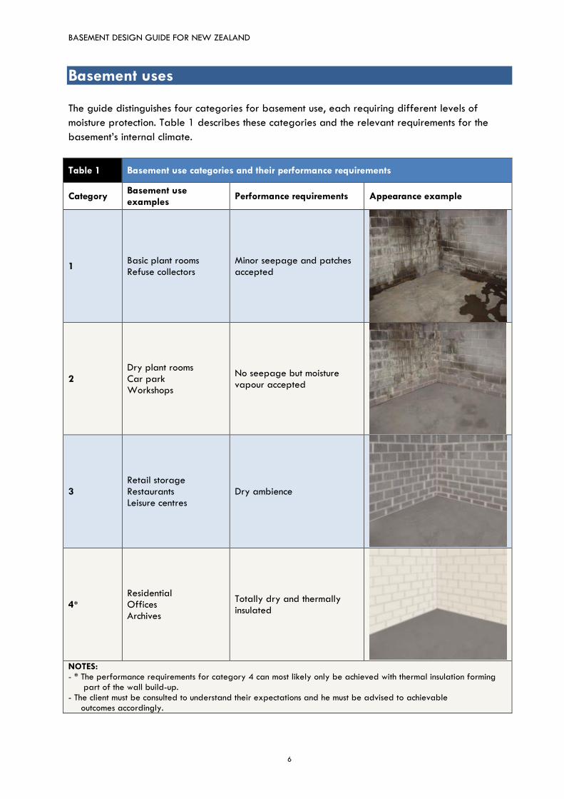
The guide distinguishes four categories for basement use, each requiring different levels of
moisture protection. Table 1 describes these categories and the relevant requirements for the
basement’s internal climate.
Table 1 Basement use categories and their performance requirements
Category Basement use examples
Performance requirements Appearance example
1 Basic plant rooms Refuse collectors
Minor seepage and patches accepted
2 Dry plant rooms Car park Workshops
No seepage but moisture vapour accepted
3 Retail storage Restaurants Leisure centres
Dry ambience
4* Residential Offices Archives
Totally dry and thermally insulated
NOTES: - * The performance requirements for category 4 can most likely only be achieved with thermal insulation forming part of the wall build-up. - The client must be consulted to understand their expectations and he must be advised to achievable outcomes accordingly.
BASEMENT DESIGN GUIDE FOR NEW ZEALAND
7
Key steps
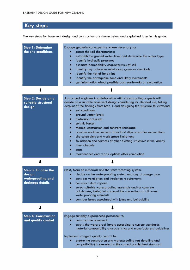
The key steps for basement design and construction are shown below and explained later in this guide.
Step 1: Determine the site conditions
Engage geotechnical expertise where necessary to:
assess the soil characteristics
establish the ground water level and determine the water type
identify hydraulic pressures
estimate permeability characteristics of soil
identify any poisonous substances, gases or chemicals
identify the risk of land slips
identify the earthquake zone and likely movements
get information about possible past earthworks or excavation
Step 2: Decide on a suitable structural design
A structural engineer in collaboration with waterproofing experts will decide on a suitable basement design considering its intended use, taking account of the findings from Step 1 and designing the structure to withstand:
soil conditions
ground water levels
hydraulic pressures
seismic forces
thermal contraction and concrete shrinkage
possible earth movements from land slips or earlier excavations
site constraints and work space limitations
foundation and services of other existing structures in the vicinity
time schedule
costs
maintenance and repair options after completion
Step 3: Finalise the design, waterproofing and drainage details
Next, focus on materials and the waterproofing system:
decide on the waterproofing system and any drainage plan
consider ventilation and insulation requirements
consider future repairs
select suitable waterproofing materials and/or concrete admixtures, taking into account the connections of different waterproofing elements
consider issues associated with joints and buildability
Step 4: Construction and quality control
Engage suitably experienced personnel to:
construct the basement
apply the waterproof layers according to current standards, material compatibility characteristics and manufacturers’ guidelines
Implement stringent quality control to:
ensure the construction and waterproofing (eg detailing and compatibility) is executed to the correct and highest standard
BASEMENT DESIGN GUIDE FOR NEW ZEALAND
8
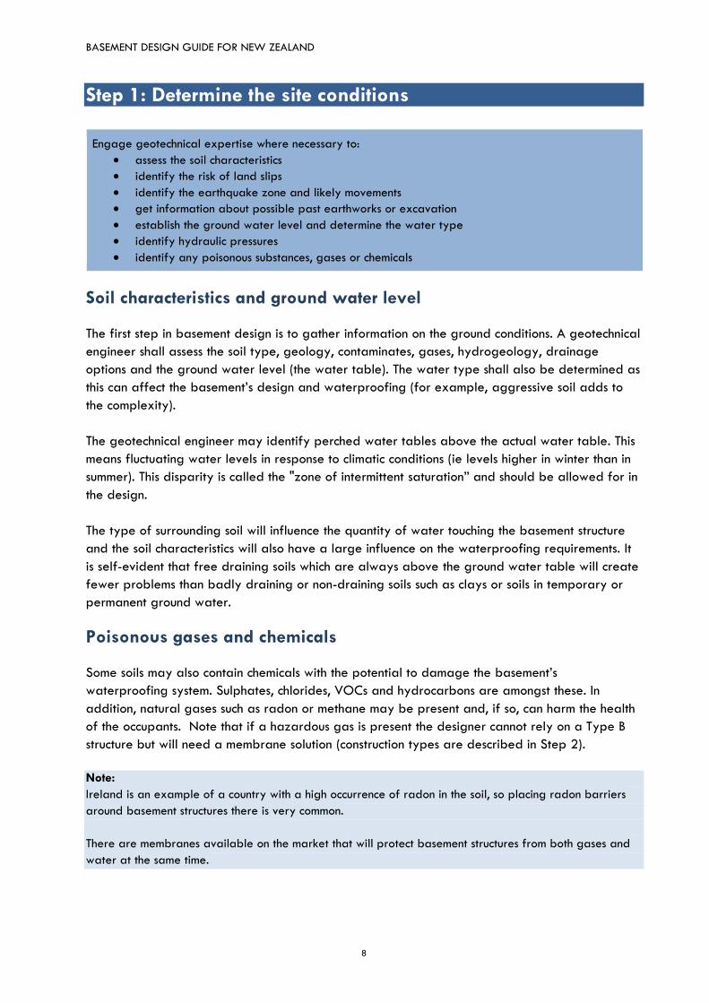
Step 1: Determine the site conditions
Engage geotechnical expertise where necessary to:
assess the soil characteristics
identify the risk of land slips
identify the earthquake zone and likely movements
get information about possible past earthworks or excavation
establish the ground water level and determine the water type
identify hydraulic pressures
identify any poisonous substances, gases or chemicals
Soil characteristics and ground water level
The first step in basement design is to gather information on the ground conditions. A geotechnical
engineer shall assess the soil type, geology, contaminates, gases, hydrogeology, drainage
options and the ground water level (the water table). The water type shall also be determined as
this can affect the basement’s design and waterproofing (for example, aggressive soil adds to
the complexity).
The geotechnical engineer may identify perched water tables above the actual water table. This
means fluctuating water levels in response to climatic conditions (ie levels higher in winter than in
summer). This disparity is called the "zone of intermittent saturation” and should be allowed for in
the design.
The type of surrounding soil will influence the quantity of water touching the basement structure
and the soil characteristics will also have a large influence on the waterproofing requirements. It
is self-evident that free draining soils which are always above the ground water table will create
fewer problems than badly draining or non-draining soils such as clays or soils in temporary or
permanent ground water.
Poisonous gases and chemicals
Some soils may also contain chemicals with the potential to damage the basement’s
waterproofing system. Sulphates, chlorides, VOCs and hydrocarbons are amongst these. In
addition, natural gases such as radon or methane may be present and, if so, can harm the health
of the occupants. Note that if a hazardous gas is present the designer cannot rely on a Type B
structure but will need a membrane solution (construction types are described in Step 2).
Note:
Ireland is an example of a country with a high occurrence of radon in the soil, so placing radon barriers
around basement structures there is very common.
There are membranes available on the market that will protect basement structures from both gases and
water at the same time.

BASEMENT DESIGN GUIDE FOR NEW ZEALAND
9
Common soil types and their drainage characteristics
Tables 3a and 3b are based on Arthur Casagrande’s classification system2 and provide
generalised drainage characteristics of the most common soil types. These tables can help
determine the ability of the soil to retain water and develop water pressure, which is important to
know before deciding on the waterproofing systems as shown in Table 4.
Note that the soil around a basement may consist of various materials and may not be uniform.
Probes should be taken at least from all perimeter sides of the structure before assessing the soil’s
overall characteristics. A geotechnical engineer or someone of similar expertise shall conduct the
assessment.
Table 3a Characteristics of well-draining soils
Symbol Soil Identification Drainage characteristics
GW Well-graded gravels & gravel-sand mixtures, little or no fines
Wide range in grain sizes & substantial amounts of all intermediate particle sizes. Over 50 % > sieve 0.074 mm. Over 50 % of gravel > sieve 4.75 mm.
Extremely good
GP Poorly-graded gravels & gravel-sand mixtures, little or no fines
Predominantly one size or a range of sizes with some intermediate sizes missing. Over 50 % > sieve 0.074 mm. Over 50 % of gravel > sieve 4.75 mm.
Extremely good
GM Silty gravels, gravel-sand-silt mixtures
Non-plastic fines or fines with low plasticity Over 50 % > sieve 0.074 mm. Over 50 % of gravel > sieve 4.75 mm.
Very good
GC Clayey gravels, gravel-sand-clay mixtures
Plastic fines. Over 50 % > sieve 0.074 mm. Over 50 % of gravel > sieve 4.75 mm.
Very good
SW Well-graded sands & gravelly sands, little or no fines
Wide range in grain sizes & substantial amounts of all intermediate particle sizes. Over 50 % > sieve 0.074 mm. Over 50 % of coarse < sieve 4.75 mm.
Good
SP Poorly-graded sands & gravelly sands, little or no fines
Predominantly one size or a range of sizes with some intermediate sizes missing. Over 50 % > sieve 0.074 mm. Over 50 % of coarse < sieve 4.75 mm.
Good
SM Silty sand, sand-silt mixtures
Non-plastic fines or fines with low plasticity. Over 50 % > sieve 0.074 mm. Over 50 % of coarse < sieve 4.75 mm.
Medium
SC Clayey sands, sand-clay mixtures
Plastic fines. Over 50 % > sieve 0.074 mm. Over 50 % of coarse < sieve 4.75 mm.
Medium
2 Arthur Casagrande - The Unified Soil Classification System, 1948

BASEMENT DESIGN GUIDE FOR NEW ZEALAND
10
Table 3b Characteristic of poorly draining soils
Symbol Soil Identification Drainage characteristics
Soils listed below are fine grained soils where over 50 % < sieve 0.074 mm
Dry strength (crushing character)
Dilatancy (reaction to shaking)
Toughness (consistency near plastic limit)
ML Inorganic silts, very fine sands, rock flour, silt or clayey fine sands
Slight to none
Quick to slow
None Poor
CL Inorganic clays of low to medium plasticity, gravely clays, sandy clays, silty clays, lean clays
Medium to high
None to very slow
Medium Poor
OL Organic silts and organic silty clays of low plasticity
Slight to medium
Slow Slight Poor
MH Inorganic silts, micaceous or diatomaceous fine sands or silts, elastic silts
Slight to medium
None to slow
Slight to medium
Very poor
CH Inorganic clays of high plasticity, fat clays
High to very high
None High Very poor
OH Organic clays of medium to high plasticity, organic silts
Medium to high
None to very slow
Slight to medium
Very poor
PT Peat and other highly organic soils
Readily identified by colour, odour and spongy feel and frequently by fibrous texture
None
BASEMENT DESIGN GUIDE FOR NEW ZEALAND
11
Step 2: Decide on a suitable structural design
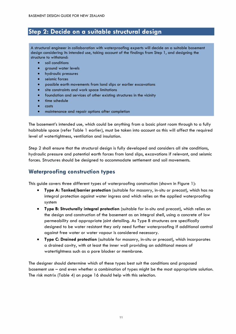
A structural engineer in collaboration with waterproofing experts will decide on a suitable basement design considering its intended use, taking account of the findings from Step 1, and designing the structure to withstand:
soil conditions
ground water levels
hydraulic pressures
seismic forces
possible earth movements from land slips or earlier excavations
site constraints and work space limitations
foundation and services of other existing structures in the vicinity
time schedule
costs
maintenance and repair options after completion
The basement’s intended use, which could be anything from a basic plant room through to a fully
habitable space (refer Table 1 earlier), must be taken into account as this will affect the required
level of watertightness, ventilation and insulation.
Step 2 shall ensure that the structural design is fully developed and considers all site conditions,
hydraulic pressure and potential earth forces from land slips, excavations if relevant, and seismic
forces. Structures should be designed to accommodate settlement and soil movements.
Waterproofing construction types
This guide covers three different types of waterproofing construction (shown in Figure 1):
Type A: Tanked/barrier protection (suitable for masonry, in-situ or precast), which has no
integral protection against water ingress and which relies on the applied waterproofing
system
Type B: Structurally integral protection (suitable for in-situ and precast), which relies on
the design and construction of the basement as an integral shell, using a concrete of low
permeability and appropriate joint detailing. As Type B structures are specifically
designed to be water resistant they only need further waterproofing if additional control
against free water or water vapour is considered necessary.
Type C: Drained protection (suitable for masonry, in-situ or precast), which incorporates
a drained cavity, with at least the inner wall providing an additional means of
watertightness such as a pore blocker or membrane.
The designer should determine which of these types best suit the conditions and proposed
basement use – and even whether a combination of types might be the most appropriate solution.
The risk matrix (Table 4) on page 16 should help with this selection.
BASEMENT DESIGN GUIDE FOR NEW ZEALAND
12
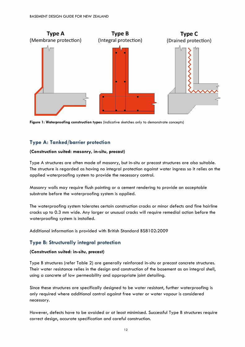
Figure 1: Waterproofing construction types (indicative sketches only to demonstrate concepts)
Type A: Tanked/barrier protection
(Construction suited: masonry, in-situ, precast)
Type A structures are often made of masonry, but in-situ or precast structures are also suitable.
The structure is regarded as having no integral protection against water ingress so it relies on the
applied waterproofing system to provide the necessary control.
Masonry walls may require flush pointing or a cement rendering to provide an acceptable
substrate before the waterproofing system is applied.
The waterproofing system tolerates certain construction cracks or minor defects and fine hairline
cracks up to 0.3 mm wide. Any larger or unusual cracks will require remedial action before the
waterproofing system is installed.
Additional information is provided with British Standard BS8102:2009
Type B: Structurally integral protection
(Construction suited: in-situ, precast)
Type B structures (refer Table 2) are generally reinforced in-situ or precast concrete structures.
Their water resistance relies in the design and construction of the basement as an integral shell,
using a concrete of low permeability and appropriate joint detailing.
Since these structures are specifically designed to be water resistant, further waterproofing is
only required where additional control against free water or water vapour is considered
necessary.
However, defects have to be avoided or at least minimised. Successful Type B structures require
correct design, accurate specification and careful construction.
BASEMENT DESIGN GUIDE FOR NEW ZEALAND
13
Adding a crystalliser admixture in the ratio of 1-2 to 100 kg cement can help to minimise cracks
and in addition provide the concrete with a ‘self healing’ property. Any noticeable cracking or
defect should be brought to the designer’s attention.
Additional protection may be used to safeguard Type B structures from aggressive chemicals.
Table 2 Details for Type B structures
Features Comments
Design – general
Waterproof concrete basements should be designed in accordance with EN 1992-3:20063 to waterproof but not vapour proof.
Additional construction information is described in NZS 3109. Also refer BSI British Standards BS8102:2009 and EN 1992-3:2006.
Reinforcement should be designed to limit crack widths. If no self-healing admixtures are used, any crack which passes through section may lead to leakage, regardless of the crack width.
Waterproofing admixtures such as crystalline mineral additives to limit crack widths and to enhance self-healing of cracks may be added in which case the admix supplier shall communicate and agree the final design with the structural engineer.
A minimum section thickness of 250 mm when no waterproofing admixtures are used and 175 mm if waterproofing admixtures are used is recommended4.
Note: Type B concrete structures are to be constructed as integral water resistant shells. Accordingly, all floors, ceilings and walls below external ground level, including the junctions between them, should be designed to resist the passage of water and moisture to the internal surface.
Design – joints
Control and construction joints, and especially penetrations are potential problem areas and require additional sealing. Water stops should be used to provide enhanced resistance to water transmission at any joints. Water stop options include:
Rubber or PVC extruded profiles cast into the concrete either on both sides of the joint or mid-depth
Metal bar strips placed mid-depth
Hydrophilic strips or crystallisation slurries forming a monolithic, waterproof compound with the concrete structure (these are applied to the joint at depth before the second cast)
Permeable hose or other sections fixed to the construction joint surface before casting the second pour, to facilitate the injection of a specialist sealing resin into the joint.
Movement joints should be avoided. If this is not possible, they shall be accessible for maintenance and specialist advice should always be sought. There are many types and materials used for waterproofing movement and expansion joints, including mechanical steel and rubber, asphalt, pitch mastic, elastomeric polyurethanes, polyurethane epoxies and hypalon strips bonded with adhesives.
3 EN 1992-3:2006 - Euro Code 2. Design of concrete structures. Liquid retaining and containing structures.
4 Recommended by National House-Building Council UK, CH 5.4, Waterproofing of basements and other below
ground structures.
BASEMENT DESIGN GUIDE FOR NEW ZEALAND
14
Table 2 Details for Type B structures
Features Comments
Design – joints (continued)
Note: The selection and type of material/fabrication of the joint will depend on the anticipated/calculated movement and also the exposure of the joint (eg will it be exposed to traffic or chemicals?) The individual application MUST be addressed by the design team. Appropriate selection is important and the manufacturer’s advice should be sought when specifying.
Selection of suitable concrete and admixtures
The principle of “Waterproof Concrete” follows the logic behind BS 8500-1:20155, where the appropriate cement is chosen for the conditions; the water/cement ratio is 0.45 or below to ensure the minimum residual capillaries within the hardened concrete; and the level of consistency chosen fits with the method of placement the contractor has decided to use. Considerations include:
Required structural strength according to the basement’s structural design
Soil, water table and possible contaminants the structure will be exposed to, and
Performance requirements depending on the basement use (refer Table 1). Requirements include:
The concrete mix specification depends on the above but shall have a maximum water/cement ratio of 0.45.
The contractor shall specify the consistency in line with his or her proposed method of placement: this is usually no less than class S36.
The admixture supplier shall recommend admixtures to waterproof the concrete, based on all the above information.
The concrete supplier shall hold a current audit certificate from the NZRMCA plant audit scheme. He or she shall receive all the above information. The concrete used shall comply with NZS 3104.
Construction
Work shall be executed by educated and trained personnel.
The construction and its system have to be fully understood by the site personnel. Meetings shall be held up front to ensure that all staff has understood the system and its outcome.
For control purposes the materials and systems used, quantities, executing personnel, time and weather conditions of the construction period shall be recorded. This shall include photo documentation, mix design certificates, test cylinders and test results for all individual pours.
Sufficient and careful vibration (and potentially re-vibration) is essential to achieve required densities and consistencies.
Early age shrinkage control by understanding ways to prevent rapid loss of moisture from the surface of the concrete and the influence of the climate conditions at the time of the pour.
5 BS 8500-1:2015 – Concrete. Complementary British Standard to BS EN 206 – Concrete specification,
performance, production and conformity 6 S3 - Concrete slump class to BS EN 12350-2. Concrete slump of range between 100 - 150 mm with
tolerances of ± 20 mm.
BASEMENT DESIGN GUIDE FOR NEW ZEALAND
15
Note: Typical reasons why Type B structures could fail are:
- permeable concrete
- honeycombing through lack of compaction
- contamination of cold joints
- cracks due to thermal contraction, shrinkage and ground movements
- poor and inadequate placement of waterbars, hydrophilic strips and joints.
Type C: Drained protection
(Construction suited: in-situ, precast, masonry)
Type C structures incorporate a drained cavity to manage any water that enters the structure. The
drainage channels must be properly formed and positioned, free from obstructions and free
flowing. It is good practice to flood test the system prior to installing the floor membrane.
For cavity construction this requires at least the inner wall providing an additional means of
watertightness, such as a pore blocker or a membrane. If the outer layer allows seepage there
will always be the drained cavity and a pump to drain any unwanted water.
As flooding could be the consequence of system failure, Type C systems shall come with a
maintenance plan.
Note:
While pore blockers provide a means of watertightness, a wall or slab may experience some form of
seepage over the long term. One example is a basement carpark underneath a garden area: seepage
through the ceiling slabs could damage the cars below.
BASEMENT DESIGN GUIDE FOR NEW ZEALAND
16
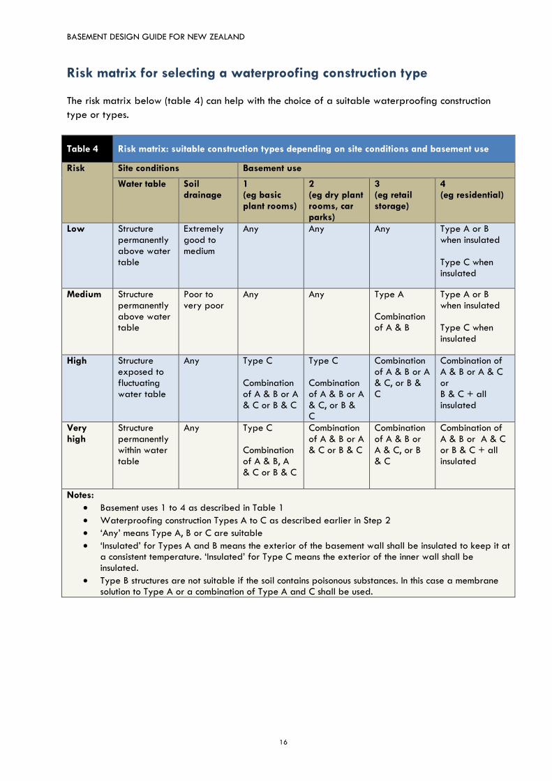
Risk matrix for selecting a waterproofing construction type
The risk matrix below (table 4) can help with the choice of a suitable waterproofing construction
type or types.
Table 4 Risk matrix: suitable construction types depending on site conditions and basement use
Risk Site conditions Basement use
Water table Soil drainage
1 (eg basic plant rooms)
2 (eg dry plant rooms, car parks)
3 (eg retail storage)
4 (eg residential)
Low Structure permanently above water table
Extremely good to medium
Any Any Any Type A or B when insulated Type C when insulated
Medium Structure permanently above water table
Poor to very poor
Any Any Type A Combination of A & B
Type A or B when insulated Type C when insulated
High Structure exposed to fluctuating water table
Any Type C Combination of A & B or A & C or B & C
Type C Combination of A & B or A & C, or B & C
Combination of A & B or A & C, or B & C
Combination of A & B or A & C or B & C + all insulated
Very high
Structure permanently within water table
Any Type C Combination of A & B, A & C or B & C
Combination of A & B or A & C or B & C
Combination of A & B or A & C, or B & C
Combination of A & B or A & C or B & C + all insulated
Notes:
Basement uses 1 to 4 as described in Table 1
Waterproofing construction Types A to C as described earlier in Step 2
‘Any’ means Type A, B or C are suitable
‘Insulated’ for Types A and B means the exterior of the basement wall shall be insulated to keep it at a consistent temperature. ‘Insulated’ for Type C means the exterior of the inner wall shall be insulated.
Type B structures are not suitable if the soil contains poisonous substances. In this case a membrane solution to Type A or a combination of Type A and C shall be used.
BASEMENT DESIGN GUIDE FOR NEW ZEALAND
17
Step 3: Finalise the design, waterproofing and drainage details
Next, focus on materials and the waterproofing system:
decide on the waterproofing system and any drainage plan
consider ventilation and insulation requirements
consider future repairs
select suitable waterproofing materials and/or concrete admixtures, taking into account the connections of different waterproofing elements
Waterproofing considerations As specifying waterproofing systems is a specialised task, a suitably qualified and experienced
person or company should be consulted for advice at the early stages. The entire waterproofing
system must be flexible so it can cope with movement arising from settlement and seismic forces
as considered by SLS7 design.
Note:
BS 8102:2009 (Code of practice for protection of below ground structures against water from the
ground) is an exemplary standard providing detailed guidance.
The connections of different waterproofing elements (eg the underslab and wall membranes) must
be considered. Using appropriate materials and wall build-ups is essential. This includes a fully
developed drainage system as well as an understanding that access around basement walls is
almost impossible post-completion. Later defects and the possibility of repairs or any back-up
system must be considered as part of the overall water-resisting design for the structure.
Basement waterproofing should not allow any water to pass through and consideration must be
given to the worst case scenario when a defect in the waterproofing system may allow seepage.
Having said this, Type B basements may allow some minor seepage, which can be acceptable for
basement uses in category 1 (refer Table 1); eg for basements used as basic plant rooms.
Any possible damage to the construction/ waterproofing in well-draining sites will not be as
severe as compared to poorly drained sites. While good draining soils will not enable the build-
up of hydrostatic water pressure, poorly drained soils carry this risk if there is heavy and/or
lengthy rainfall.
Basements constructed in poorly drained soils may require a back barrier in addition to the initial
waterproofing system. This barrier is also required for basements set below the ground water
table.
7 SLS - Serviceability Limit State to NZS 1170. Level of Strain to a building which after exposure can
continue to be used for its intended purpose without the need for repair.
BASEMENT DESIGN GUIDE FOR NEW ZEALAND
18
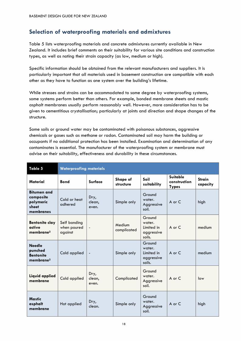
Selection of waterproofing materials and admixtures
Table 5 lists waterproofing materials and concrete admixtures currently available in New
Zealand. It includes brief comments on their suitability for various site conditions and construction
types, as well as noting their strain capacity (as low, medium or high).
Specific information should be obtained from the relevant manufacturers and suppliers. It is
particularly important that all materials used in basement construction are compatible with each
other as they have to function as one system over the building’s lifetime.
While stresses and strains can be accommodated to some degree by waterproofing systems,
some systems perform better than others. For example, bonded membrane sheets and mastic
asphalt membranes usually perform reasonably well. However, more consideration has to be
given to cementitious crystallisation; particularly at joints and direction and shape changes of the
structure.
Some soils or ground water may be contaminated with poisonous substances, aggressive
chemicals or gases such as methane or radon. Contaminated soil may harm the building or
occupants if no additional protection has been installed. Examination and determination of any
contaminates is essential. The manufacturer of the waterproofing system or membrane must
advise on their suitability, effectiveness and durability in these circumstances.
Table 5 Waterproofing materials
Material Bond Surface Shape of structure
Soil suitability
Suitable construction Types
Strain capacity
Bitumen and composite polymeric sheet membranes
Cold or heat adhered
Dry, clean, even.
Simple only
Ground water. Aggressive soil.
A or C high
Bentonite clay active membrane2
Self bonding when poured against
- Medium complicated
Ground water. Limited in aggressive soils.
A or C medium
Needle punched Bentonite membrane2
Cold applied - Simple only
Ground water. Limited in aggressive soils.
A or C medium
Liquid applied membrane
Cold applied Dry, clean, even.
Complicated
Ground water. Aggressive soil.
A or C low
Mastic asphalt membrane
Hot applied Dry, clean.
Simple only
Ground water. Aggressive soil.
A or C high
BASEMENT DESIGN GUIDE FOR NEW ZEALAND
19
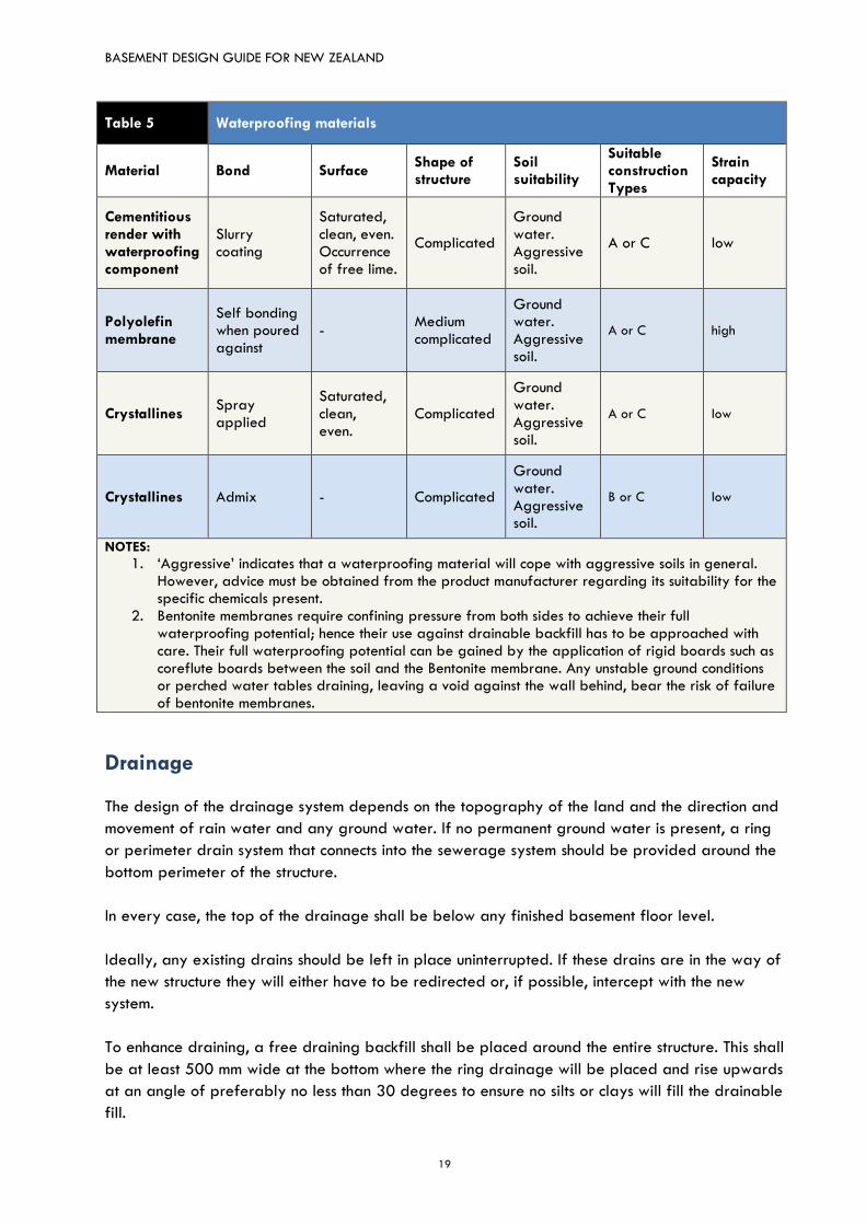
Table 5 Waterproofing materials
Material Bond Surface Shape of structure
Soil suitability
Suitable construction Types
Strain capacity
Cementitious render with waterproofing component
Slurry coating
Saturated, clean, even. Occurrence of free lime.
Complicated
Ground water. Aggressive soil.
A or C low
Polyolefin membrane
Self bonding when poured against
- Medium complicated
Ground water. Aggressive soil.
A or C high
Crystallines Spray applied
Saturated, clean, even.
Complicated
Ground water. Aggressive soil.
A or C low
Crystallines Admix - Complicated
Ground water. Aggressive soil.
B or C low
NOTES:
1. ‘Aggressive’ indicates that a waterproofing material will cope with aggressive soils in general. However, advice must be obtained from the product manufacturer regarding its suitability for the specific chemicals present.
2. Bentonite membranes require confining pressure from both sides to achieve their full waterproofing potential; hence their use against drainable backfill has to be approached with care. Their full waterproofing potential can be gained by the application of rigid boards such as coreflute boards between the soil and the Bentonite membrane. Any unstable ground conditions or perched water tables draining, leaving a void against the wall behind, bear the risk of failure of bentonite membranes.
Drainage
The design of the drainage system depends on the topography of the land and the direction and
movement of rain water and any ground water. If no permanent ground water is present, a ring
or perimeter drain system that connects into the sewerage system should be provided around the
bottom perimeter of the structure.
In every case, the top of the drainage shall be below any finished basement floor level.
Ideally, any existing drains should be left in place uninterrupted. If these drains are in the way of
the new structure they will either have to be redirected or, if possible, intercept with the new
system.
To enhance draining, a free draining backfill shall be placed around the entire structure. This shall
be at least 500 mm wide at the bottom where the ring drainage will be placed and rise upwards
at an angle of preferably no less than 30 degrees to ensure no silts or clays will fill the drainable
fill.
BASEMENT DESIGN GUIDE FOR NEW ZEALAND
20
The ring drainage system shall be covered with at least 500 mm x 500 mm permanent gravel.
This gravel shall be surrounded with a woven filter medium to assure no non-draining material will
come near the drainage system and cause congestion.
Where no external drain can be installed and the wall sits immediately against the soil (for
example, for in-ground ‘excavated and cast’ wall construction systems such as diaphragm walls) a
Type C wall with a drained cavity wall system is recommended. The outer wall shall be
reinforced to achieve waterproofing and shall have a concrete with no more than 0.45 w/c ratio.
The cavity bottom in Type C walls is at the same time the drain channel and sits at least 150 mm
below any internal floor level. The drain channel shall be built with collection dents and a pump
system to remove any water that passes into the cavity.
For basements in permanent ground water, the floor shall also be drained. A double floor system
allows for water collection below the finished floor and a pump system will remove any water
passing through the walls or the floor.
Ventilation and insulation
While the main aspects of basement design relate to its structure and protection against any
ground or drain water, it is also important that no internally generated moisture or condensation
shall harm the building, its kept goods or occupants.
Ventilation/ air exchange and/or thermal insulation may be necessary:
to minimise or prevent condensation
for reasons of health and hygiene, and
to meet performance requirements for the basement’s proposed use (refer Table 1).
Minimising condensation
Relative humidity levels in many parts of New Zealand are such that at 12.5°C the air is
saturated and condensation will form on surfaces (this is known as the dew point). According to
NIWA8, the mean earth temperature at 10 cm depth will drop below this level during the four
months from June to September.
Considering that in-ground structures can contain greater humidity, condensation may form even
at higher temperatures. Frequent surface condensation can cause mould which affect’s people’s
respiratory health and can damage interior artefacts such as carpets, furniture or stored items.
Bearing in mind that basement walls are made waterproof and therefore do not allow
permeability to the exterior as above ground walls do, designers must take steps either to guide
any surplus moisture out of the basement or to ensure the ambient temperature is always above
dew point.
8 National Institute of Water and Atmospheric Research
BASEMENT DESIGN GUIDE FOR NEW ZEALAND
21
There are several useful online dew point calculators9 available providing mould risk and
preservation evaluations based on the project’s specific ground and ambient temperatures and
occurrence of relative humidity.
Professional and accurate measurements of the hydrothermal behaviour can be obtained by
using a dynamic building simulation tool such as WUFI®10.
Ventilating the basement
Ventilation is important to help address condensation, moisture to escape and also to provide
suitable air quality for the basement’s intended use. Ventilation can either be provided naturally,
through windows or louvres, or mechanically. As mechanical ventilation is rather expensive this
should be an incentive to find a natural ventilated solution.
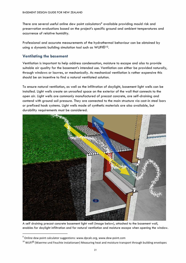
To ensure natural ventilation, as well as the infiltration of daylight, basement light wells can be
installed. Light wells create an unroofed space on the exterior of the wall that connects to the
open air. Light wells are commonly manufactured of precast concrete, are self-draining and
contend with ground soil pressure. They are connected to the main structure via cast-in steel bars
or prefixed hook systems. Light wells made of synthetic materials are also available, but
durability requirements must be considered.
A self draining precast concrete basement light well (image below), attached to the basement wall,
enables for daylight infiltration and for natural ventilation and moisture escape when opening the window.
9 Online dew point calculator suggestions: www.dpcalc.org, www.dew-point.com
10 WUFI® (Waerme und Feuchte instationaer) Measuring heat and moisture transport through building envelopes
BASEMENT DESIGN GUIDE FOR NEW ZEALAND
22
Thermal insulation
Thermal insulation of the wall and the floor may also be required to help prevent condensation
and so the basement is suitable for its intended use. To avoid surface condensation, thermal
insulation has to be installed to move the dew point away from the inner surface. This shall be
installed at the exterior and must be moisture resistant (eg XPS or foamglass). Thermal insulation
should also be provided around any windows where the temperature, especially in winter, drops
below the dew point.
Exterior insulation protects the structure and waterproofing membrane from the extremes of the
soil and from climate swings. The wall and floor maintain a stable temperature and thus thermally
induced expansion and contraction is reduced to a minimum. This minimises the risk of cracks. The
temperature of externally insulated walls and floors will always be near the indoor temperature
and, therefore, humid interior air is unlikely to condense on the inner basement surfaces.
Note:
Internal insulation risks the accumulation of condensation moisture within itself. If this moisture is not
removed it can lead to fungal growth and a mouldy environment.
Exterior basement insulation shall be moisture proof and able to keep its volume under hydraulic
and soil pressure so its thermal performance is not compromised. Ideally, the exterior side of this
insulation should have a drain dimple sheet applied to enhance drainage down the wall.
Further recommendations
It is not recommended to line basement walls with any material that is likely to promote mould
growth.
Prior to the installation of any wall lining, the concrete must first dry fully. The average time for
25 mm thick concrete to dry is about one month. As such, a 200 mm wall requires at least 8
months to dry. Due to the impermeability of the external water proofing membrane the concrete
will only dry to the inside.
Avoid using vinyl or paper based wallpaper and vapour barrier paints. It is not recommended to
line the walls with plaster boards as its paper layer is prone to mould growth. Emulsion paints
and lime plaster are acceptable coatings. Lime plaster in particular has extremely good mould
resisting properties.
Future repairs
As any watertightness system could fail and result in flooding it is important at the design stage to
consider either installing back-up protection installed or specifying a repair regime. Note that
Type C walls always have the advantage that the cavity will function as back up, whereas failure
of a Type A or B wall is likely to require excavation to repair the exterior protection.
If excavation is not feasible for some reason, the design should provide for a process of remedial
works to reseal from the inside. Internal membrane and waterproofing solutions are possible if
BASEMENT DESIGN GUIDE FOR NEW ZEALAND
23
they are compatible with the initial system. Particular attention is required at all joint, junctions
and penetrations.
Generic design details
Examples of design details for Types A and C construction systems are provided on the following
pages.
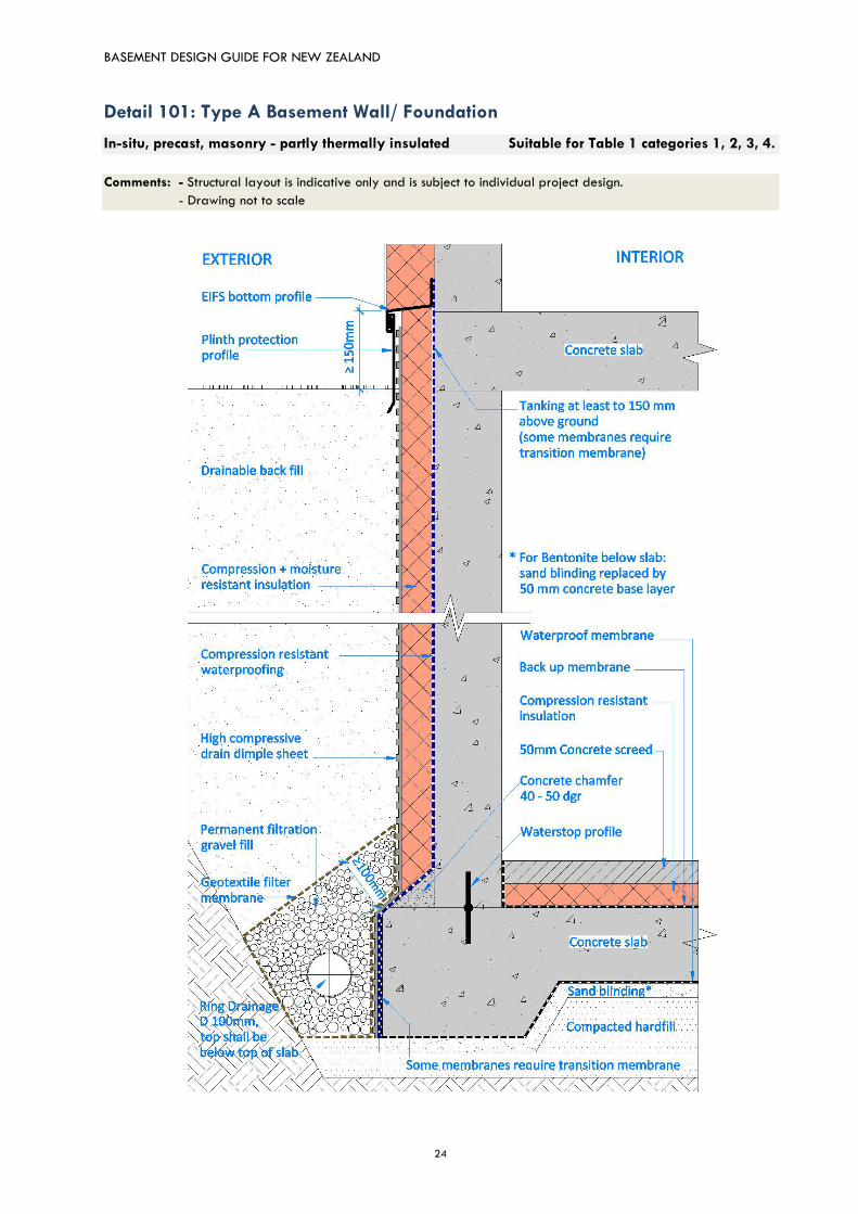
Details 101, 102 and 103 are suitable for all Table 1 categories including ‘Residential’. Thermal
insulation ensures the wall and floor dries consistently to the interior, while also managing ground
moisture, ground source vapour drive, interior condensation and construction moisture effectively.
However, Detail 101 has the potential to retain sufficient moisture that enables the development
of mould when the room is not heated and ventilated11. The inner wall to floor section is
particularly at risk, where the lack of insulation creates cold bridging. This detail is only suitable
for Table 1, Category 4 if the space is heated to a consistent temperature of at least 18°C and
ventilated properly at all times.
It is recommended that all below ground residential spaces are maintained at temperatures
between 18°C and 24°C and are regularly ventilated, natural or mechanical.
Note:
At intersections of waterproofing membranes, eg floor to wall, ensure membranes are compatible and
bond so the waterproofing is not compromised. Some membranes require a transition membrane.
11
CCANZ Foundation Detail WUFI® 2D modelling by Sustainable Engineering Ltd. 10 Oct 2016
BASEMENT DESIGN GUIDE FOR NEW ZEALAND
24
Detail 101: Type A Basement Wall/ Foundation
In-situ, precast, masonry - partly thermally insulated Suitable for Table 1 categories 1, 2, 3, 4.
Comments: - Structural layout is indicative only and is subject to individual project design.
- Drawing not to scale

BASEMENT DESIGN GUIDE FOR NEW ZEALAND
25
Detail 102: Type A Basement Wall/ Foundation
In-situ, precast, masonry - thermally insulated Suitable for Table 1 categories 1, 2, 3, 4.
Comments: - Structural layout is indicative only and is subject to individual project design.
- Drawing not to scale
BASEMENT DESIGN GUIDE FOR NEW ZEALAND
26
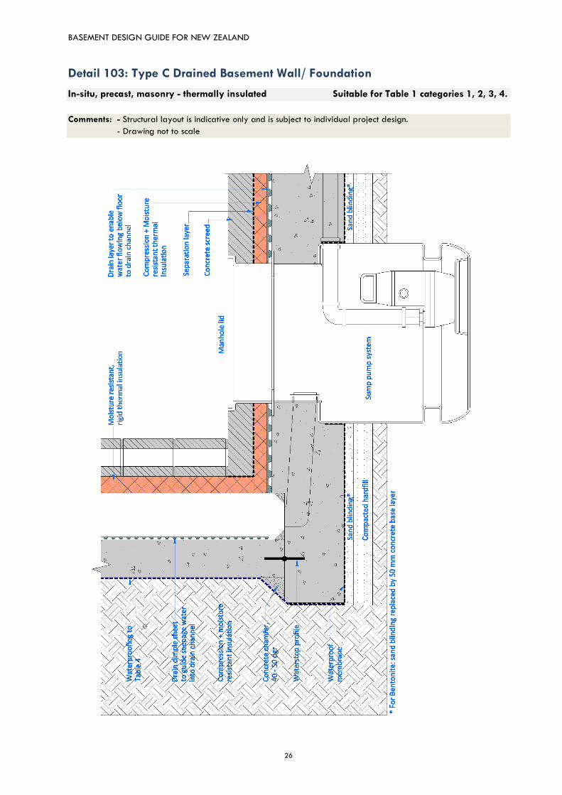
Detail 103: Type C Drained Basement Wall/ Foundation
In-situ, precast, masonry - thermally insulated Suitable for Table 1 categories 1, 2, 3, 4.
Comments: - Structural layout is indicative only and is subject to individual project design.
- Drawing not to scale
BASEMENT DESIGN GUIDE FOR NEW ZEALAND
27
Step 4: Construction and quality control
Engage suitably experienced personnel to:
construct the basement
apply the waterproof layers according to current standards, material compatibility characteristics and manufacturers’ guidelines
Implement stringent quality control to:
ensure the construction and waterproofing application (eg detailing and compatibility) is executed to the correct and highest standard
Step 4 of the process includes constructing the basement, installing any associated drainage and
applying any waterproofing that is required.
It is essential that this step is carried out by experienced personnel and that the waterproof
layers are applied according to current standards, material compatibility characteristics and
manufacturers’ guidelines. As noted earlier, all materials must be compatible with each other as
they have to function as one system over the building’s lifetime.
For all basement types counts, any joints and especially penetrations are potential problem areas
and require additional sealing. Water stops should be used to provide enhanced resistance to
water transmission at any joints.
Water stop options include:
rubber or PVC extruded profiles cast into the concrete either on both sides of the joint or
mid-depth
metal bar strips placed mid-depth
hydrophilic strips or crystallisation slurries forming a monolithic, waterproof compound
with the concrete structure (these are applied to the joint at depth before the second
cast)
permeable hose or other sections fixed to the construction joint surface before casting the
second pour, to facilitate the injection of a specialist sealing resin into the joint.
Step 4 also requires stringent quality control. This not only includes material and system checks but
also observation of the works to ensure that the construction and waterproofing application (eg
detailing and compatibility) is executed to the correct and highest standard.
It should be self-explanatory that a functioning drainage system is one of the first steps after
excavation works have been accomplished. Installing a perimeter footing drainage system that
connects into the sewerage will relieve hydrostatic pressure from surface water and table water
in any drainable soil. The larger the slab, the more susceptible it will be to pressure from the
water table. Accordingly, for larger slabs consider having a minimum 100 mm layer of rounded
gravel distributed evenly below the slab area for drainage.
Install drainable backfill when all construction is completed. However, delay backfilling until all
concrete has gained the full target strength. Early backfilling against green (non-cured) concrete
puts huge pressure on the walls - cracking and failure is the usual outcome.
BASEMENT DESIGN GUIDE FOR NEW ZEALAND
28
Resources
Relevant standards, codes and specifications
- New Zealand Building Code, Schedule 1 to the Building Regulations 1992
- NZS 3101:2006, Concrete structures standard - The design of concrete structures
- NZS 3104:2003, Specification for concrete production
- NZS 3109:1997, Concrete construction
- NZS 3106:2009, Design of concrete structures for the storage of liquids
- NZS 3122:2015, Specification for Portland and blended cements (General and special purpose)
- NZS 3121:1986, Specification for water and aggregate for concrete
- BS EN 1992-3:2006 Eurocode 2: design of concrete structures, liquid retaining and containing
structures
- BS 8102:2009 Code of practice for protection of below ground structures against water from ground
- BS EN 12970:2000, Mastic asphalt for waterproofing - Definitions, requirements and test methods
- DIN EN 18195:2011-12 (Part 1-10), Waterproofing of buildings
- BS EN 13969:2004, Flexible sheets for waterproofing. Bitumen damp proof sheets including bitumen
basement tanking sheets. Definitions and characteristics.
- BS EN 13967:2012, Flexible sheets for waterproofing. Plastic and rubber damp proof sheets including
plastic and rubber basement tanking sheet. Definitions and characteristics.
Recommended publications
- Association of Specialist Underpinning Contractors (ASUC): Guidelines on safe and efficient
basement construction directly below or near to existing structures 2013.
- British Cement Association (BCA): Basement Waterproofing Design Guide 1994
- British Cement Association (BCA): Basement Waterproofing Site Guide 1994
- Building Research Establishment (BRE), Special Digest 1:2005 - Concrete in aggressive ground
- BS EN 1992-1-1:2014+A1:2014, Eurocode2: Design of concrete structures, part 1-1 general
rules and rules for buildings
- BS EN 206:2013, Concrete, part 1: Specification, performance, production and conformity
- BS 5454:2012, Recommendation for the storage and exhibition of archival documents BSI 2000
- BS 8002:2015, Code of practice for earth retaining structures
- BS 8500:2015, Parts 1&2, Concrete - Complementary British Standard to BS EN 206-1
- British Structural Waterproofing Association (BSWA), Waterproofing Existing Basements 2005

BASEMENT DESIGN GUIDE FOR NEW ZEALAND
29
- Construction Industry Research and Information Association (CIRIA), Report C660, Early - age
thermal crack control in concrete 2007
- Construction Industry Research and Information Association (CIRIA) Report R140, Water resisting
basements 1995
- Mineral Products Association (MPA), Concrete Basements: Guidance on design and construction
of in-situ concrete basement structures 2012
- National House-Building Council (NHBC), Waterproofing of basements and other below ground
structures 2015
- AS/NZS 4058, 2007 Precast concrete pipes (pressure and non-pressure)
- The Basement Information Centre (TBIC), The Building Regulations 2010 - Basements for
Dwellings Guidance Document 2014
- The Basement Information Centre (TBIC): Basements: Waterproofing - General Guidance to BS
8102: 2009 (Design Guide)
BASEMENT DESIGN GUIDE FOR NEW ZEALAND
30
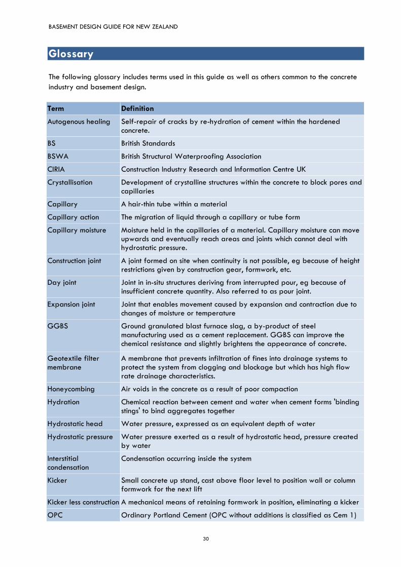
Glossary
The following glossary includes terms used in this guide as well as others common to the concrete
industry and basement design.
Term Definition
Autogenous healing Self-repair of cracks by re-hydration of cement within the hardened concrete.
BS British Standards
BSWA British Structural Waterproofing Association
CIRIA Construction Industry Research and Information Centre UK
Crystallisation Development of crystalline structures within the concrete to block pores and capillaries
Capillary A hair-thin tube within a material
Capillary action The migration of liquid through a capillary or tube form
Capillary moisture Moisture held in the capillaries of a material. Capillary moisture can move upwards and eventually reach areas and joints which cannot deal with hydrostatic pressure.
Construction joint A joint formed on site when continuity is not possible, eg because of height restrictions given by construction gear, formwork, etc.
Day joint Joint in in-situ structures deriving from interrupted pour, eg because of insufficient concrete quantity. Also referred to as pour joint.
Expansion joint Joint that enables movement caused by expansion and contraction due to changes of moisture or temperature
GGBS Ground granulated blast furnace slag, a by-product of steel manufacturing used as a cement replacement. GGBS can improve the chemical resistance and slightly brightens the appearance of concrete.
Geotextile filter membrane
A membrane that prevents infiltration of fines into drainage systems to protect the system from clogging and blockage but which has high flow rate drainage characteristics.
Honeycombing Air voids in the concrete as a result of poor compaction
Hydration Chemical reaction between cement and water when cement forms 'binding stings' to bind aggregates together
Hydrostatic head Water pressure, expressed as an equivalent depth of water
Hydrostatic pressure Water pressure exerted as a result of hydrostatic head, pressure created by water
Interstitial condensation
Condensation occurring inside the system
Kicker Small concrete up stand, cast above floor level to position wall or column formwork for the next lift
Kicker less construction A mechanical means of retaining formwork in position, eliminating a kicker
OPC Ordinary Portland Cement (OPC without additions is classified as Cem 1)
BASEMENT DESIGN GUIDE FOR NEW ZEALAND
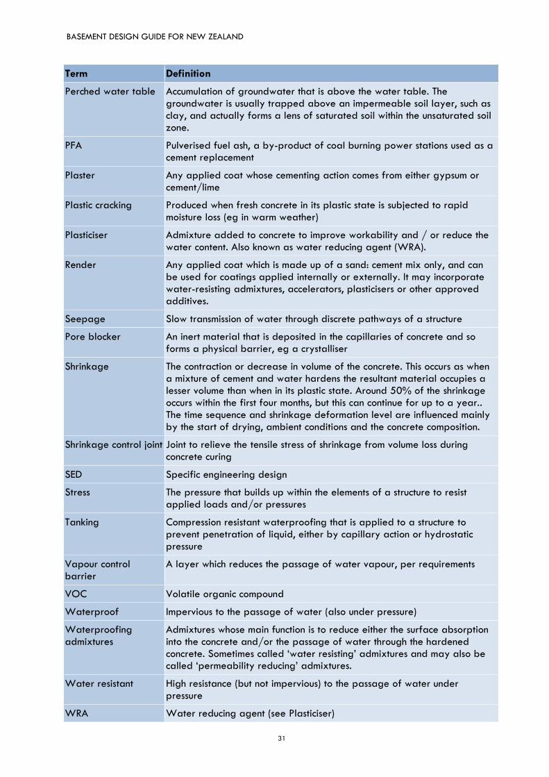
31
Term Definition
Perched water table Accumulation of groundwater that is above the water table. The groundwater is usually trapped above an impermeable soil layer, such as clay, and actually forms a lens of saturated soil within the unsaturated soil zone.
PFA Pulverised fuel ash, a by-product of coal burning power stations used as a cement replacement
Plaster Any applied coat whose cementing action comes from either gypsum or cement/lime
Plastic cracking Produced when fresh concrete in its plastic state is subjected to rapid moisture loss (eg in warm weather)
Plasticiser Admixture added to concrete to improve workability and / or reduce the water content. Also known as water reducing agent (WRA).
Render Any applied coat which is made up of a sand: cement mix only, and can be used for coatings applied internally or externally. It may incorporate water-resisting admixtures, accelerators, plasticisers or other approved additives.
Seepage Slow transmission of water through discrete pathways of a structure
Pore blocker An inert material that is deposited in the capillaries of concrete and so forms a physical barrier, eg a crystalliser
Shrinkage The contraction or decrease in volume of the concrete. This occurs as when a mixture of cement and water hardens the resultant material occupies a lesser volume than when in its plastic state. Around 50% of the shrinkage occurs within the first four months, but this can continue for up to a year.. The time sequence and shrinkage deformation level are influenced mainly by the start of drying, ambient conditions and the concrete composition.
Shrinkage control joint Joint to relieve the tensile stress of shrinkage from volume loss during concrete curing
SED Specific engineering design
Stress The pressure that builds up within the elements of a structure to resist applied loads and/or pressures
Tanking Compression resistant waterproofing that is applied to a structure to prevent penetration of liquid, either by capillary action or hydrostatic pressure
Vapour control barrier
A layer which reduces the passage of water vapour, per requirements
VOC Volatile organic compound
Waterproof Impervious to the passage of water (also under pressure)
Waterproofing admixtures
Admixtures whose main function is to reduce either the surface absorption into the concrete and/or the passage of water through the hardened concrete. Sometimes called ‘water resisting’ admixtures and may also be called ‘permeability reducing’ admixtures.
Water resistant High resistance (but not impervious) to the passage of water under pressure
WRA Water reducing agent (see Plasticiser)

BASEMENT DESIGN GUIDE FOR NEW ZEALAND
32

BASEMENT DESIGN GUIDE FOR NEW ZEALAND
33
BASEMENT DESIGN GUIDE FOR NEW ZEALAND
34
CCANZ BG 01
Cement & Concrete Association of New Zealand www.ccanz.org.nz


![Eec 0verview 2009a[1]](https://img.dokumen.tips/doc/110x75/546d5161b4af9f662c8b5402/eec-0verview-2009a1.jpg)