Embed Size (px)
DESCRIPTION
fa
Citation preview

LSP COMPLEX PROJECT
Package A – Olefins and Central Utility Plant ITB Volume I – Annex C
Rev.: 0 Long Son Petrochemicals Co., Ltd
Document No.: CON - 006 Sheet: 1 of 64
________________________________________________________________________________________________
Confidential : This document is confidential and must not be copied or reproduced except with the express
permission of Long Son Petrochemicals Co., Ltd.
PROJECT TECHNICAL SPECIFICATION
CON – 006
SITE INSPECTION AND TESTING
0 15/09/2009 ISSUE FOR LSP PROJECT HHM PCS
REV. DATE DESCRIPTION PREPARED CHECKED APPROVED
LSP COMPLEX PROJECT
Package A – Olefins and Central Utility Plant ITB Volume I – Annex C
Rev.: 0 Long Son Petrochemicals Co., Ltd
Document No.: CON - 006 Sheet: 2 of 64
TABLE OF CONTENTS
1. SCOPE .................................................................................................... 4
1.1. PURPOSE .............................................................................................................. 4
1.2. RESPONSIBILITY .................................................................................................. 4
1.3. CONTRACTOR’s SCOPE OF SERVICE ............................................................... 4
1.4. RELATED ENGINEERING SPECIFICATIONS...................................................... 4
2. GENERAL ............................................ ................................................... 4
2.1. INSPECTION PERSONNEL................................................................................... 4
2.2. WELDING INSPECTION ........................................................................................ 4
2.3. WELDING PROCEDURE ....................................................................................... 4
2.4. TESTING ON SITE................................................................................................. 4
2.5. TESTS OUTSIDE THE SITE .................................................................................. 4
2.6. SCOPE OF TESTING............................................................................................. 4
2.7. ACCEPTANCE STANDARD................................................................................... 4
2.8. OWNER INSPECTION ........................................................................................... 4
2.9. DOCUMENTATION ................................................................................................ 4
3. PRESSURE VESSELS, HEAT EXCHANGER, AIR COOLERS ...... ....... 4
3.1. GENERAL............................................................................................................... 4
3.2. FIELD WELDS ........................................................................................................ 4
3.3. TESTING OF FIELD WELD.................................................................................... 4
3.4. PRESSURE TESTING............................................................................................ 4
3.5. DOCUMENTATION ................................................................................................ 4
3.6. STORAGE TANKS ................................................................................................. 4
4. MECHANICAL EQUIPMENTS.............................. .................................. 4
4.1. GENERAL............................................................................................................... 4
4.2. PUMPS (CENTRIFUGAL, RECIPROCATING, METERING, POSITIVE DIPLACEMENT PUMPS, EXCLUDING FIRE WATER PUMPS)..................................................... 4
4.3. FIRE WATER PUMPS, INCLUDING DIESEL ENGINES....................................... 4
4.4. CENTRIFUGAL COMPRESSORS AND DRIVERS, EXCEPT INSTRUMENT AIR COMPRESSORS................................................................................................... 4
4.5. INSTRUMENT AIR COMPRESSORS, INCLUDING DRYERS.............................. 4
4.6. RECIPROCATING OXYGEN COMPRESSORS.................................................... 4
4.7. GENERAL AND SPECIAL PURPOSE STEAM TURBINES .................................. 4

LSP COMPLEX PROJECT
Package A – Olefins and Central Utility Plant ITB Volume I – Annex C
Rev.: 0 Long Son Petrochemicals Co., Ltd
Document No.: CON - 006 Sheet: 3 of 64
4.8. INDUSTRIAL COMBUSTION GAS TURBINES ..................................................... 4
4.9. CENTRIFUGAL FANS ............................................................................................ 4
4.10. LUBE OIL AND SEAL OIL SYSTEM ...................................................................... 4
5. PIPING .................................................................................................... 4
5.1. GENERAL............................................................................................................... 4
5.2. ORGANIZATION AND RESPONSIBILITY ............................................................. 4
5.3. CHECK OF MATERIALS RECEIVED .................................................................... 4
5.4. PREFABRICATION ................................................................................................ 4
5.5. WELDING ............................................................................................................... 4
5.6. TESTS AND EXAMINATIONS ............................................................................... 4
5.7. SCOPE OF “RT” TESTING..................................................................................... 4
5.8. EVALUATION CRITERIA ....................................................................................... 4
5.9. REPAIRS ................................................................................................................ 4
5.10. CHECK OF PIPING COMPONENTS ..................................................................... 4
5.11. PRESSURE AND LEAK TESTS............................................................................. 4
5.12. FLUSHING, PICKLING, DRYING........................................................................... 4
5.13. PAINTING AND INSULATION................................................................................ 4
5.14. MECHANICAL COMPLETION ............................................................................... 4
6. INSTRUMENTATION .............................................................................. 4
6.1. GENERAL............................................................................................................... 4
6.2. DEFINITIONS ......................................................................................................... 4
6.3. INSPECTION AND TESTING DOCUMENTS ........................................................ 4
6.4. INSPECTION AND TESTING REQUIREMENTS .................................................. 4
6.5. INSPECTION AND TESTING BEFORE INSTALLATION COMMENCEMENT ..... 4
6.6. INSPECTION AFTER INSTALLATION COMMENCEMENT.................................. 4
6.7. TESTING AFTER INSTALLATION COMMENCEMENT ........................................ 4
6.8. INSPECTION FOR INSTRUMENT SUPPLIED WITHIN PACKAGE UNIT............ 4
6.9. INSPECTION REPORTS........................................................................................ 4
6.10. TEST RESULTS ..................................................................................................... 4
6.11. OVERALL INSTALLATION CERTIFICATE............................................................ 4
6.12. STARTUP PERSONNEL........................................................................................ 4
7. ELECTRICAL AND COMMUNICATION FACILITIES............ ................. 4
7.1. SCOPE.................................................................................................................... 4
7.2. GENERAL............................................................................................................... 4

LSP COMPLEX PROJECT
Package A – Olefins and Central Utility Plant ITB Volume I – Annex C
Rev.: 0 Long Son Petrochemicals Co., Ltd
Document No.: CON - 006 Sheet: 4 of 64
7.3. REASONS, TYPES AND PREREQUISITES OF SITE INSPECTION AND TESTS
............................................................................................................................... 4
7.4. AS AN INTEGRAL PART OF ALL PARTICULAR SITE INSPECTIONS AND TESTS, CONTRACTOR SHALL BE RESPONSIBLE FOR THE FOLLOWING: ................ 4
7.5. SPECIFIC REQUIREMENTS FOR FIELD INSPECTIONS AND TESTS OF ELECTRICAL AND COMMUNICATION EQUIPMENT ......................................... 4
8. MISCELLANEOUS ITEMS................................ ...................................... 4

LSP COMPLEX PROJECT
Package A – Olefins and Central Utility Plant ITB Volume I – Annex C
Rev.: 0 Long Son Petrochemicals Co., Ltd
Document No.: CON - 006 Sheet: 5 of 64
1. SCOPE
This Specification stipulates the basic scope of inspection activities for construction work on the
site, irrespective of whether the plant components to be erected arrives on the site as complete,
pre- assembled or semi-finished unit.
1.1. PURPOSE
This specification shall enable the Contractor to incorporate the tests and inspections required
by the OWN E R or the Project Specifications in his scope of services and guarantee.
1.2. RESPONSIBILITY
1.2.1. Compliance by the Contractor with this specification does not relieve him from his responsibility
to determine and include in his services any test activities exceeding the minimum requirements
which, in his opinion, are necessary to fulfill guarantee and prove the quality of construction
work on the site.
1.2.2. The scope makes no claims to completeness. The Contractor is responsible to cover in his
detailed site inspection procedure and/or specifications all necessary test requirements
considering all requirements of this Project Specification, covering also those
equipment/material items which are not specifically mentioned herein.
1.2.3. The Contractor shall guarantee that all equipment/material is of first class quality and
successfully inspected and tested.
1.3. CONTRACTOR'S SCOPE OF SERVICE
The Contractor shall include in his scope of services detailed inspection and test procedures to
be approved by the Owner incorporating also requirements mentioned herein before starting the
construction work. The inspection and test procedures shall include hold points for Owner
inspection.
1.4. RELATED ENGINEERING SPECIFICATIONS
• Project Specification SP-010 Equipment Preservation
• Project Specification SP-009 Painting
• Project Specification SP-006 Thermo Insulation Design

LSP COMPLEX PROJECT
Package A – Olefins and Central Utility Plant ITB Volume I – Annex C
Rev.: 0 Long Son Petrochemicals Co., Ltd
Document No.: CON - 006 Sheet: 6 of 64
• ME-002 Storage Tank
• CON-010 Fabrication and Field Works of Piping
• EE-001 General Electrical Design Specification

LSP COMPLEX PROJECT
Package A – Olefins and Central Utility Plant ITB Volume I – Annex C
Rev.: 0 Long Son Petrochemicals Co., Ltd
Document No.: CON - 006 Sheet: 7 of 64
2. GENERAL
2.1. INSPECTION PERSONNEL
2.1.1. The Contractor shall prepare organization schedules showing the responsibilities of the
inspection personnel. An assigned chief inspector is fully responsible for the following tasks
independently of the Site Management.
• The inspection personnel shall be trained and qualified for the work to be performed by
them.
• All necessary specifications and applicable Codes shall be made available by Contractor
on site.
• Tests and inspections shall be carried out in conformation with their Codes and
Standards and related specifications.
• The test equipments to be used shall meet the local laws and regulations. (Evaluate test
results are a prerequisite for the selection of the test equipments)
• Scope and sequence of testing shall be adhered to.
2.1.2. The Contractor is responsible for inviting the Third Party inspector to the test and assuring the
proper performance of the testing activities.
2.1.3. Owner shall always have the right to approve or reject inspection personnel of Contractor
without clarification.
2.2. WELDING INSPECTION
2.2.1. The Contractor shall assign a weld inspection group to report to the chief inspector. The weld
inspection group has the right to give instructions regarding:
• Storage and selection of the welding filler metals and auxiliaries
• Pre- and post- weld heat treatment
• Welders’ performance qualifications
• Assignment of welders

LSP COMPLEX PROJECT
Package A – Olefins and Central Utility Plant ITB Volume I – Annex C
Rev.: 0 Long Son Petrochemicals Co., Ltd
Document No.: CON - 006 Sheet: 8 of 64
• Welding equipments
• Checking the repair procedure and repair work
• Welding documentation
2.2.2. All reports carried by chief inspector shall be also available to Owner representation.
2.3. WELDING PROCEDURE
2.3.1. The Contractor shall supply and prepare welding procedures for field welding showing the:
• Welding method
• Welding filler metals
• Qualification of the welders (including welding test specimens)
• Weld shape
• Welding sequence and position
• Pre- and post- weld heat treatment
• Weld examination and evaluation criteria
• Scope of weld examination
2.3.2. The welding inspector shall check that the welding data sheets are adhered to during welding
regarding the welders, welding procedures, filler metals and weld tests, the requirements of the
Project Specification for Welding.
2.3.3. For materials which are not covered by ASTM, the Contractor shall furnish material specific
processing documentation from the Vendor for Owner approval prior to use.
2.4. TESTING ON SITE
Unless otherwise stipulated in the Project Specifications or Vendor instructions, the following
test shall be made:
2.4.1. Destructive tests shall be made in accordance with the requirements specified in ASTM A to G.

LSP COMPLEX PROJECT
Package A – Olefins and Central Utility Plant ITB Volume I – Annex C
Rev.: 0 Long Son Petrochemicals Co., Ltd
Document No.: CON - 006 Sheet: 9 of 64
2.4.2. Non-destructive tests shall be made in accordance with the requirements specified in ASME
Section V.
2.5. TESTS OUTSIDE THE SITE
If tests which have been specified cannot be performed on the Site, they shall be made in
accordance with Paragraph 2.4 by a test institute approved by the chief inspector without
additional cost to the Owner.
2.6. SCOPE OF TESTING
2.6.1. The scope of testing is taken from the Project Specifications, Codes and Standards or this
Specification.
2.6.2. The scope of testing may be extended if it is required more by quality assurance. The new
scope of testing shall then be established jointly by the chief inspector and the weld inspection
group.
2.6.3. The Owner shall be informed thereof in writing.
2.7. ACCEPTANCE STANDARD
2.7.1. The acceptance standard is laid down in the Project Specifications, Codes and Standards and
shall be strictly adhered to.
2.7.2. In case of doubt, the requirements of the Codes and Standards shall apply Paragraph 2.8
Owner INSPECTION.
2.8. OWNER INSPECTION
2.8.1. The Owner and/or its representative may witness the tests and inspections at their own
discretion.
2.8.2. The Contractor shall submit FIELD INSPECTION NOTICE (FIN) to the Owner by daily basis for
field inspection. Other than field inspection, FIN shall be submitted to the Owner not later than 5
working days prior to scheduled inspection date.
2.8.3. The Owner has the right to have tests repeated on Contractor’s cost if FIN is not submitted in
time.

LSP COMPLEX PROJECT
Package A – Olefins and Central Utility Plant ITB Volume I – Annex C
Rev.: 0 Long Son Petrochemicals Co., Ltd
Document No.: CON - 006 Sheet: 10 of 64
2.9. DOCUMENTATION
2.9.1. All test results shall be entered in forms issued for the particular tests. The forms shall be
signed by the authorized person.
2.9.2. The test reports shall clearly refer to the object tested.
LSP COMPLEX PROJECT
Package A – Olefins and Central Utility Plant ITB Volume I – Annex C
Rev.: 0 Long Son Petrochemicals Co., Ltd
Document No.: CON - 006 Sheet: 11 of 64
3. PRESSURE VESSELS, HEAT EXCHANGER, AIR COOLERS
3.1. GENERAL
3.1.1. This chapter applies to tests and inspections of field welds on pressure vessels.
3.1.2. Generally, these plant components except storage tanks are delivered completely to the Site.
For the usual piping connection work, the requirements given in Paragraph 5 of this
Specification shall be observed.
3.2. FIELD WELDS
3.2.1. If field welds are necessary, the Vendor’s instructions and the Project Specifications shall be
complied with.
3.2.2. The weld inspection group shall check the work documentation and supervises welding and any
possible heat treatments and testing.
3.2.3. If any subsequent repairs to plant components are required on site, the repair procedure is part
of the Vendor’s scope. The weld inspection group shall check the Vendor’s repair instructions
for suitably supervise the repair work and report the results to Owner.
3.2.4. Auxiliary structures and transport devices which are welded directly to pressure walls of the
plant component and must be removed shall not be knocked off. They shall be removed
mechanically and the connection points on the pressure wall shall be ground flushed and
checked for cracks. Repair welding requires the procedure approved by Owner prior to start of
the work.
3.2.5. Welding on plant components subjected to final heat treatment at the Vendor’s works is not
permitted in any case.
3.3. TESTING OF FIELD WELD
3.3.1. SCOPE OF TESTING
• Generally, all field welds of pressure parts shall be 100 % tested. Butt welds shall be
radiographic tested as per codes and standards. Fillet welds of austenitic and non-
magnetic materials shall be liquid penetrant tested.
LSP COMPLEX PROJECT
Package A – Olefins and Central Utility Plant ITB Volume I – Annex C
Rev.: 0 Long Son Petrochemicals Co., Ltd
Document No.: CON - 006 Sheet: 12 of 64
• Carbon steel fillet welds shall be subjected to a magnetic particle examination.
3.3.2. ACCEPTANCE STANDARD
The ASME Code shall be the basis for evaluating the welds to be examined.
3.4. PRESSURE TESTING
If pressure testing after welding is required, Paragraph 7.4 of the Project Specification shall be
applied.
3.5. DOCUMENTATION
All test activities and results shall be documented. The activities prior to mechanical completion
shall be included.
3.6. STORAGE TANKS
3.6.1. Delivery, fabrication and testing on the site shall be accordance with the requirements of Project
Specification. The Contractor’s weld inspection group shall assure that the instructions from the
tank Vendor are complied with.
3.6.2. The tank Vendor shall advise the Contractor’s weld inspection group all of tests to be made in
the course of fabrication. If the test results do not meet the specified quality standard, the scope
of testing shall be taken by the Contractor’s chief inspector after consultation with the welding
supervisors and weld inspection group.
3.6.3. All test results and dimensional checks shall be recorded according to Paragraph 2.9 and 3.5.
3.6.4. Spherical tanks containing liquefied hydrocarbon and / or substances governed by local laws
and regulations shall be performed the inspection and test as required by the regulations or the
project specification ME-002 Storage Tank whichever is more stringent. The Contractor shall be
responsible for all works and cooperating with government's inspector as his satisfaction to
achieve government approval and certificate for such storage tanks.

LSP COMPLEX PROJECT
Package A – Olefins and Central Utility Plant ITB Volume I – Annex C
Rev.: 0 Long Son Petrochemicals Co., Ltd
Document No.: CON - 006 Sheet: 13 of 64
4. MECHANICAL EQUIPMENTS
4.1. GENERAL
This chapter applies to the field tests and inspections for the mechanical equipments.
4.1.1. Detailed test procedures shall be prepared by the Contractor and submitted to the Owner for
review prior to start the construction work.
4.1.2. Prior to the test runs for each machine the Contractor shall submit to the Owner the following
certificates:
• Alignment protocol
• Protocol of stress-free pipe connection
• Internal inspection report (cleaning, clearance check etc.)
If applicable, in addition, the Contractor has to deliver certificates for hydrostatic pressure test,
radiographic examination of welds, liquid penetrant examination, etc.
4.1.3. A detailed check list has to be prepared by Contractor for the individual steps from the
beginning of the erection up to the tests under operating conditions. The check list shall also
contain information about the function and tightness of the mechanical seal, vibration of the
machine for the specified operating range, etc.
4.1.4. Detailed records of the test runs containing capacity, pressures, temperatures, vibrations,
electric current consumption, steam consumption, cooling water consumption, etc. shall be
prepared by the Contractor during the individual tests of the equipment and submitted to the
Owner for approval.
4.1.5. Prior to test run of the machinery, the interlocking control electrical safety protection system,
and observation system shall be checked for function and used during the test runs of the
machinery.
• If machines are tested with fluid other than the operating product, some functions of the
interlocking system which can't be used have to be bridged.
• Before carrying out tests on the machines with the original media/gases all functions of
the interlocking system shall be checked for function and used.

LSP COMPLEX PROJECT
Package A – Olefins and Central Utility Plant ITB Volume I – Annex C
Rev.: 0 Long Son Petrochemicals Co., Ltd
Document No.: CON - 006 Sheet: 14 of 64
4.1.6. If during the specified test duration the test has to be stopped due to machinery failures, the test
run has to be repeated after all causes have been corrected.
4.1.7. If there is any deviations in this specification due to operation condition and a circumstance.
Contractor shall inform to Owner and shall then discuss with Owner regarding correct action
such as test duration, test method, etc. for Owner approval.
4.2. PUMPS (CENTRIFUGAL, RECIPROCATING, METERING, P OSITIVE DIPLACEMENT PUMPS, EXCLUDING FIRE WATER PUMPS)
4.2.1. All pumps shall be mechanically tested with water or suitable fluids specified by the Contractor
for at least 4 hours of continuous operation. Every hour bearing temperature and vibration shall
be recorded.
4.2.2. All pumps shall be subjected to a performance test of at least 14 days of continuous operation
under operating conditions. If one operating and one stand-by pump are installed they are
required to change over from operating to standby after two weeks.
4.3. FIRE WATER PUMPS, INCLUDING DIESEL ENGINES
4.3.1. A mechanical test run of at least 4 hours shall be performed with the diesel engine according to
ISO 3046. For the diesel engine of the fire pump system, a mechanical test run of at least 4
hours shall be performed, according to ISO 3046.
4.3.2. Complete fire water pumps with diesel engine shall be tested under operating conditions for at
least 14 days, according to NFPA 20.
4.4. CENTRIFUGAL COMPRESSORS AND DRIVERS, EXCEPT IN STRUMENT AIR COMPRESSORS
4.4.1. The mechanical test run for all centrifugal compressor units shall be carried out with air or any
other suitable fluid specified by the Contractor for at least 48 hours of continuous operation.
When abnormal condition is found, during the mechanical test run, detailed check shall be
carried out for corrective action.
4.4.2. All centrifugal compressor units shall be tested with the original gas under operating conditions
for at least 14 days of continuous operation.
LSP COMPLEX PROJECT
Package A – Olefins and Central Utility Plant ITB Volume I – Annex C
Rev.: 0 Long Son Petrochemicals Co., Ltd
Document No.: CON - 006 Sheet: 15 of 64
4.5. INSTRUMENT AIR COMPRESSORS, INCLUDING DRYERS
Each instrument air compressor unit including dryer shall be tested for at least 14 days of
continuous operation under operating conditions.
4.6. RECIPROCATING OXYGEN COMPRESSORS
4.6.1. Mechanical test runs and initial oxygen runs shall be performed in according with IGC-Standard
10/81 section 6.2 and instructions from machine Vendor.
4.6.2. The following additions shall apply to IGC-Standard 10/81, section 6.2 Site work:
• (Clarification)
A mechanical test run of at least 48 hours continuous operation shall be performed. After
the 48-hour test run, the valves, piston and bearings of the machine shall be visually
inspected.
• (Clarification)
The oxygen test run shall be performed for at least 14 days continuous operation.
4.7. GENERAL AND SPECIAL PURPOSE STEAM TURBINES
4.7.1. All general-purpose steam turbines shall be mechanically tested for at least 4 hours of
continuous operation.
• Every hour bearing temperature and vibration shall be recorded.
• Before mechanical test, the trip speed of the turbine shall be tested at least 3 times.
4.7.2. General purpose steam turbines and special-purpose steam turbines equipped with oil systems
which is according to API 614 excluding gear type turbines shall be mechanically tested for at
least 6 hours' continuous operation. Every hour bearing temperature and vibration shall be
recorded.
When abnormal condition is found, during the mechanical test run, the bearings and blades of
all steam turbines shall be visually inspected.
4.7.3. All general and special-purpose steam turbines shall be tested for at least 14 days of
continuous operation under operating conditions together with the driven machine.
LSP COMPLEX PROJECT
Package A – Olefins and Central Utility Plant ITB Volume I – Annex C
Rev.: 0 Long Son Petrochemicals Co., Ltd
Document No.: CON - 006 Sheet: 16 of 64
4.8. INDUSTRIAL COMBUSTION GAS TURBINES
4.8.1. Each gas turbine shall be mechanically tested with the driven machine for at least 48 hours of
continuous operation. Before this test run, the trip speed must be tested.
After the mechanical test run, bearings of the turbine and the gear shall be visually inspected.
4.8.2. Each gas turbine shall be tested for at least 14 days continuous operation under operating
conditions together with the driven machine.
4.9. CENTRIFUGAL FANS
4.9.1. All centrifugal fans shall be mechanically tested for at least 4 hours of continuous operation with
all its auxiliaries. Every hour bearing temperature and vibration shall be recorded.
4.9.2. When abnormal condition is found, during the mechanical test run, the bearings of centrifugal
fan shall be visually inspected.
4.9.3. Each centrifugal fan shall be tested for at least 14 days of continuous operation under operating
conditions.
4.10. LUBE OIL AND SEAL OIL SYSTEM
4.10.1. The complete oil unit shall be flushed and cleaned with oil till clear of dirt and debris as specified
by the Contractor/Vendor.
4.10.2. After carrying out the functional tests of the oil system, a test run of at least 14 days continuous
operation shall be performed for the original system using the specified oil.
• The test run to the oil unit shall be carried out in accordance with API 614.
• While the oil unit is flushed the bearing and shaft seals of the lubricated machinery shall
be by-passed.

LSP COMPLEX PROJECT
Package A – Olefins and Central Utility Plant ITB Volume I – Annex C
Rev.: 0 Long Son Petrochemicals Co., Ltd
Document No.: CON - 006 Sheet: 17 of 64
5. PIPING
5.1. GENERAL
This chapter applies to the tests and inspections of piping.
5.2. ORGANIZATION AND RESPONSIBILITY
5.2.1. The Contractor shall prepare pertinent organization schedules to guarantee the quality
assurance for prefabrication and final installation of piping. The organization schedules shall
also determine the technical responsibilities.
5.2.2. Regarding the quality assurance of piping installation, the warehouse, prefabrication areas and
other piping assembly areas shall be organized so that quality assurance is guaranteed. For
this, the Contractor shall prepare a detailed procedure.
5.3. CHECK OF MATERIALS RECEIVED
5.3.1. All piping components received shall be checked. The quality and compliance with the Codes
and Standards of all structural parts shall be proved by certificates. Structural parts which do not
meet these requirements must be rejected. Random check for the material specification shall be
done against certificates by Contractor’s cost.
5.3.2. Re-stamping of pipes and elbows shall be done by the pertinent field inspectors.
5.4. PREFABRICATION
5.4.1. Systematic process of parts withdrawn from the site warehouse for prefabrication or final
installation shall be properly handled, protected, stored before their final use.
5.4.2. All piping components shall be preserved. The Contractor shall make appropriate rooms for
prefabrication available. Piping components of carbon steel and of austenitic steel shall be kept
separately in the prefabrication area. The prefabricated piping sections shall be properly stored
such as capping, marking, grouping, etc. before further use.
5.5. WELDING

LSP COMPLEX PROJECT
Package A – Olefins and Central Utility Plant ITB Volume I – Annex C
Rev.: 0 Long Son Petrochemicals Co., Ltd
Document No.: CON - 006 Sheet: 18 of 64
5.5.1. The Contractor shall prepare welding data sheets for the basic material combinations to be
welded. These data sheets shall be based on the Codes and Standards given in the Project
Specifications for welding.
5.5.2. Before starting the welding work, all data sheets, PQR and welders' certificates shall be
submitted to the weld inspection group. If there are any doubts, the weld inspection group shall
check the welder's quality standard by welding test specimens. Wherever possible, welding
shall be limited to prefabrication work.
5.6. TESTS AND EXAMINATIONS
The weld examinations shall be made after the last heat treatment based on the data sheets
and on a test schedule. The examinations shall be performed using test equipment from which
optimal test results for the welds to be examined can be expected. Random test to piping welds
must include all weld joints.
5.6.1. VISUAL CHECK OF WELDS
The examination shall be 100% for all types of welds. The examination shall be carried out
according to ASME Boiler and Pressure Vessel Code (BPVC) Section V, Article 9.
5.6.2. BUTT WELDS
• Radiographic examination shall be performed in accordance with:
• ASME Section V, Article 2
• Paragraph 341.3.2 and Paragraph 344.5 of ASME B31.3
• Paragraph 136.4.5 of ASME B31.1.
• The scope of the random test has to be extended by Contractor as per ASME B31.3,
Paragraph 341.3.4 if the test results show that the welds are not free of unacceptable
defects.
5.6.3. EXAMINATION OF FILLET WELDS
• The fillet welds shall be subjected to a magnetic particle or liquid penetrant examination.
The liquid penetrant method is being used for nonmagnetic materials. The examination is
made as per Boiler and Pressure Vessel Code.
• Article 7, Section V for Magnetic Particle method

LSP COMPLEX PROJECT
Package A – Olefins and Central Utility Plant ITB Volume I – Annex C
Rev.: 0 Long Son Petrochemicals Co., Ltd
Document No.: CON - 006 Sheet: 19 of 64
• Article 6, Section V for Liquid Penetrant method.
• Welds subjected to heat treatment, may be radio-graphed prior to the last heat treatment,
if after the heat treatment an additional liquid penetrant examination is made.
5.6.4. HARDNESS TEST
If a heat treatment is required by ANSI/ASME B 31.3 Chapter V, 331.1.1 and Table 331.1.1, the
hardness of the weld shall be verified. If piping material and weldment to be expanded to sour
environment, hardness shall be verified as requirement of NACE standard MR0175-94.
5.7. SCOPE OF “RT” TESTING
The scope of testing for the materials/combination used shall be determined by the Contractor
appropriate to the stress to which the material is exposed. The scope of testing in general shall
be conformed to CON-010 Fabrication and Field Works of Piping.
5.8. EVALUATION CRITERIA
5.8.1. For all welds, the error limits as per ANSI/ASME B 31.3, Chapter V, 328; ANSI/ASME Chapter
VI, 341,344 shall be adhered to.
5.8.2. The maximum hardness values are to be taken from the ASME 31.3, Table 331.1.1 and NACE
standard MR0175-94.
5.9. REPAIRS
The repairs shall be made in accordance with ASME B31.3, Chapter V, 328.6.
5.10. CHECK OF PIPING COMPONENTS
The Contractor’s piping specialists shall check the installed piping components for compliance
with the P & I diagrams, piping drawings, isometric drawings and bills of materials. If any
doubts, material mix up test shall be made.
5.11. PRESSURE AND LEAK TESTS
5.11.1. The Contractor’s piping specialists shall compile pressure test systems before starting the
pressure tests. After completion of all welding, heat treatment and testing of the systems to be
pressure-tested, the weld inspection group shall give the approval for pressure testing. The
pressure testing shall be made according to ASME B31.3, Chapter VI, 345.

LSP COMPLEX PROJECT
Package A – Olefins and Central Utility Plant ITB Volume I – Annex C
Rev.: 0 Long Son Petrochemicals Co., Ltd
Document No.: CON - 006 Sheet: 20 of 64
5.11.2. The water to be used for the hydrostatic test shall be specified by the Contractor. If different
materials are used in the hydrostatic test system, such as piping of carbon steel/heat exchanger
tubes of stainless steel, water with a limited chloride (less than 10 PPM) content shall be used
for this system.
5.11.3. The butt welds of pipes which cannot be subjected to a hydrostatic test shall be 100% radio-
graphed. Subsequently, a leakage test is made. This examination is also performed, for all
separable connections.
5.11.4. For the leakage test with air or nitrogen, appropriate safety measures shall be taken considering
the local requirements.
5.12. FLUSHING, PICKLING, DRYING
For piping systems to be pickled and/or flushed and dried, the requirements of Project
Specification SP-010 Equipment Preservation shall be complied with.
5.13. PAINTING AND INSULATION
5.13.1. After completion of the test described in Paragraph 5.10 and 5.11, approval for painting and
insulation shall be given. The requirements of Project Specifications for painting (SP-009
Painting) and insulation (SP-006 Thermo Insulation Design) shall be complied with.
5.13.2. Insulation has to be inspected, in particular, for conformation with the specified insulation
thickness, numbers of spacers, metal thickness of the weather jacket and proper installation of
the jackets (appropriate overlap, tightness to water) and the inspection results have to be
recorded.
5.13.3. Thermal conductivity coefficients, apparent densities and the required sound insulation figures
of the insulating materials have to be verified.
5.13.4. Surface preparation (degree of rust removal), reference surfaces, workability of the insulating
materials shall conform with the manufacturer's handling instructions. For instance regarding
humidity, application of insulating materials and thickness per insulation layer shall be inspected
/ supervised and the inspection results shall be recorded.
5.14. MECHANICAL COMPLETION
After completion of all work on the piping systems and compilation of the drawings and test
documentation, the Contractor shall notify the Owner of mechanical completion.

LSP COMPLEX PROJECT
Package A – Olefins and Central Utility Plant ITB Volume I – Annex C
Rev.: 0 Long Son Petrochemicals Co., Ltd
Document No.: CON - 006 Sheet: 21 of 64
6. INSTRUMENTATION
6.1. GENERAL
6.1.1. This standard should be used for the inspection and testing of all instrumentation and
monitoring equipment for all plant components before and after installation on Site.
6.1.2. The contractor's personnel shall be competent, qualified and fully conversant with the types of
equipment to be tested and where necessary the contractor shall arrange for his personnel to
attend relevant training course.
6.1.3. A critical path analysis network shall be provided by the contractor and agreed by Owner. This
shall define the overall sequence of the testing on the project. Any subsequent deviation from
this program shall be agreed in writing.
6.1.4. The contractor shall, at all items, observe and comply with Vietnam and international safety
regulation.
6.1.5. The contractor shall set up and maintain a quality assurance system to ensure that all work is
carried out in full accordance with the requirements of the relevant parts of BS 5750: 1987 / ISO
9000 - quality system.
6.1.6. The contractor shall set up and maintain a quality assurance system to ensure that all work is
carried out in accordance with the relevant specification.
6.1.7. The contractor shall obtain approval from owner before power or pneumatic supplies are
switched on to any instrument, panel, and control system of plant.
6.2. DEFINITIONS
Terms used in this specification are defined as follows:
6.2.1. Maximum working pressure means the set pressure of safety valves for process piping and
equipments.
6.2.2. Design pressure of instruments means the maximum pressure guaranteed by the
manufacturer to which the pressurized parts of the instruments may be subjected without
affecting the performance of the instruments.

LSP COMPLEX PROJECT
Package A – Olefins and Central Utility Plant ITB Volume I – Annex C
Rev.: 0 Long Son Petrochemicals Co., Ltd
Document No.: CON - 006 Sheet: 22 of 64
6.3. INSPECTION AND TESTING DOCUMENTS
Contractor shall provide the documents listed below to perform site inspection and testing
activities as minimum.
• Instrument list
• Technical data sheets
• Installation drawings
• Hook-up drawings
• Loop diagrams
• Circuit diagrams
• Wiring diagrams
• Terminal connection diagrams
• Interlock logic and sequence diagrams
• Manufacturer's recommended inspection and testing procedures
• Installation check sheets
• Testing reports
• Calibration reports
• Etc.
Format of installation check sheets, testing reports, and calibration reports shall be prepared by
Contractor and approved by Owner.
6.4. INSPECTION AND TESTING REQUIREMENTS
6.4.1. INSPECTORS FOR INSPECTION AND TESTING
The inspectors must be familiar with the necessary inspection, testing, and adjustment works for
the installed instrumentation.
6.4.2. CALIBRATION FACILITIES

LSP COMPLEX PROJECT
Package A – Olefins and Central Utility Plant ITB Volume I – Annex C
Rev.: 0 Long Son Petrochemicals Co., Ltd
Document No.: CON - 006 Sheet: 23 of 64
Contractor shall provide the dedicated calibration workshop in the site or nearby which meets
the requirements of the international standard.
Contractor shall not use the calibration workshop for any other activity.
Entry inside the calibration workshop shall be permitted only to calibration technicians and
inspectors from Contractor’s and owner's side.
The calibration room shall be an air conditioner room. The temperature, humidity, and the
quality of air inside shall be controlled suitably for the requirement of calibration room according
to the international standard. A thermometer shall be installed inside the room and the set
temperature shall be noted down in testing and calibration reports.
The test equipment and the instruments to be calibrated shall be handled and maintained in
suitable manner in order to maintain their guaranteed accuracy. Contractor shall maintain test
certificates for the calibration of all test equipment by a third party and the calibration procedure
shall be traceable to international standards.
Contractor shall also have standard procedures for regular calibration of the test equipment.
6.4.3. INSPECTION AND TESTING ACTIVITIES
The inspection and testing activities shall be included, but not limit to, the followings.
• Inspection and testing before installation commencement
- Factory Acceptance Test (FAT)
- Visual inspection
- Calibration
- Etc.
• Inspection and testing after installation commencement
- Visual inspection
- Leakage test and pressure test in pneumatic lines and impulse lines
- Inspection of the cables, screening, and protective system for proper connection
- Functional test

LSP COMPLEX PROJECT
Package A – Olefins and Central Utility Plant ITB Volume I – Annex C
Rev.: 0 Long Son Petrochemicals Co., Ltd
Document No.: CON - 006 Sheet: 24 of 64
- Loop test
- Interlock logic and sequence test
- Performance test
- Site Acceptance Test (SAT)
- Etc.
6.4.4. OTHER REQUIREMENTS
The inspection and testing plan including date, procedure, etc. shall be specified by the
Contractor and agreed with the Owner. Owner shall have the rights to witness all the
inspections and tests. All test equipment and consumables shall be provided by the Contractor.
The contractor shall submit list of all test equipment to be used. This shall be revised and
agreed with the Owner before testing is commenced. The list shall contain, but not limit to, the
following.
• Manufacturer
• Instrument Type
• Type Number
• Quality Class
• Instrument Test & Calibration certificate from approved authorities
6.5. INSPECTION AND TESTING BEFORE INSTALLATION COM MENCEMENT
6.5.1. The Factory Acceptance Test (FAT) of the following instrument systems shall be performed by
Contractor at Manufacturer’s or Vendor’s workshop and approved by Owner prior to delivery.
The inspection and test procedure shall be sent to Owner for approval at least 1 week prior to
the test. The tested systems shall include, but not limit to, the followings.
• DCS system
• ESD system
• F&G system

LSP COMPLEX PROJECT
Package A – Olefins and Central Utility Plant ITB Volume I – Annex C
Rev.: 0 Long Son Petrochemicals Co., Ltd
Document No.: CON - 006 Sheet: 25 of 64
• GC system and Analyzer House
• Continuous Emission Monitoring System (CEMS)
• COD Analyzer System
• Other analyzer systems
• Custody Transfer meter system
• Truck loading meter system
• Pelletizing system
• Etc.
6.5.2. All instruments shall be visually inspected by the instrument subcontractor prior to issue from
Contractor’s stores and any discrepancies shall be reported in writing to the contractor
immediately.
6.5.3. Scale design, instrumentation symbols and texturing shall be checked at this stage.
6.5.4. Prior to installation, all instruments shall be calibrated by the Contractor in the site workshop.
Calibration method and procedure shall be sent to Owner for approval at least 1 week prior to
the calibration. The calibration process shall be traceable to international standards. The
calibrated instruments shall include, but not limit to, the followings.
6.5.5. Contractor shall use the following inspection and test items of each instrument as a guideline.
The inspection and test of equipment which are not listed below shall be proposed by
Contractor and approved by Owner.
• TRANSMITTERS, GAUGE, AND SIGNAL CONVERTERS:
Calibrate at 0, 25, 50, 75, and 100% of measurement range
• CONTROL VALVES:
Each control valve shall be checked against the data sheets
Check to the linearity of the valve lift as against control signal: 0, 25, 50, 75, 100 % direct
and reverse

LSP COMPLEX PROJECT
Package A – Olefins and Central Utility Plant ITB Volume I – Annex C
Rev.: 0 Long Son Petrochemicals Co., Ltd
Document No.: CON - 006 Sheet: 26 of 64
Behavior on control air failure
• SWITCHES: (INCLUDE TEMPERATURE SWITCH, PRESSURE SWITCH, FLOW
SWITCH, LEVEL SWITCH, ETC.)
Checking the switch function (NC or NO)
Adjustment of the necessary switch points
Checking the switch hysteresis
• SAFETY VALVES
Each safety valve shall be checked against the data sheets.
Bench test for all safety valves by applying pressure to the design level shall be carried
out no earlier than 90 days prior to Mechanical Completion.
Lead seal shall be replaced and certified by Vendor’s representative at site if the
adjustment of spring is requested.
6.5.6. A pre printed calibration sticker showing the tag no, manufacturer's serial number, date of
calibration, calibration report serial number and initials of the person who has done the
calibration shall be put on the instrument immediately after calibration.
6.6. INSPECTION AFTER INSTALLATION COMMENCEMENT
6.6.1. Contractor shall use the following inspection and test items of each instrument as a guideline.
The inspection and test of equipment which are not listed below shall be proposed by
Contractor and approved by Owner.
• PANELS
Panels are held in place and are fixed firmly in accordance with the related drawings.
Panels are correctly mounted vertically.
The surface of panels is cleaned and has not been dented or scratched.
• INSTRUMENT CABLE DUCTS
Instrument cable ducts are laid in according to the routes shown in the drawings using the
material specified for the construction and sizes.

LSP COMPLEX PROJECT
Package A – Olefins and Central Utility Plant ITB Volume I – Annex C
Rev.: 0 Long Son Petrochemicals Co., Ltd
Document No.: CON - 006 Sheet: 27 of 64
Instrument cable ducts are fixed by the procedure shown in the drawings.
The inside of instrument cable ducts has no projection which may damage cables or
wires.
The worked parts of the galvanized steel plates fabricated or welded at construction site
are repaired according to the specified procedure.
Instrument cable ducts are certainly fitted with all cover plates.
6.6.2. IMPULSE PIPING / TUBING
• VISUAL INSPECTION
Impulse piping/tubing is laid in accordance with the route shown in the drawings.
The materials specified for standards, sizes and quality are used.
The relative elevation and direction of pressure taps and instrument are as shown in the
drawing.
Seal pots, condensate pots, etc. are assembled in the same or specified elevation.
Impulse piping/tubing is sloped as specified.
The division of high and low pressure connection of differential pressure instruments is
correct.
• PRESSURE TESTS AND LEAK TESTS
Those tests shall generally be performed without disconnection of impulse piping/tubing
and the test pressure shall be limited to the design pressure of the instrument.
Pressure tests and leak tests shall be carried out simultaneously in accordance with the
following procedure (except for 900 # rating and over).
Nitrogen or air shall be used for the pressurization of impulse piping/tubing.
The test pressure shall be 1.25 times the maximum working pressure.
No change on the impulse piping/tubing is confirmed after pressurized at least five
minutes at the test pressure.
During the test, no leakage from impulse piping/tubing is checked by soapy water.

LSP COMPLEX PROJECT
Package A – Olefins and Central Utility Plant ITB Volume I – Annex C
Rev.: 0 Long Son Petrochemicals Co., Ltd
Document No.: CON - 006 Sheet: 28 of 64
Remarks: The pressurization must be done slowly to maintain the safety.
For 900 # rating and over, pressure tests and leak tests shall be carried out individually.
Fluid, pressure and duration is as follows
• PRESSURE TESTS
Fluid: water
Pressure: 1.5 times the maximum working pressure
Duration: 5 minutes
• LEAK TESTS
Fluid: Air
Pressure: 1.1 times the maximum working pressure
Duration: 3 minutes
6.6.3. SUPPLY AIR PIPING /TUBING
• VISUAL INSPECTION
Supply air piping/tubing is arranged as shown in the drawings.
The materials specified for standards, sizes and quality are used.
The piping/tubing method around instruments is correct.
The piping/tubing is routed avoiding an adverse effect from a heat source and is not
under the hot or cold insulation materials of process piping and equipments.
The piping/tubing is arranged or supported avoiding the vibration and thermal expansion
of process piping or of equipments.
• LEAK TESTS
Leak tests shall be performed after cleaning check and the procedure shall be as follows:
Instrument air is used for leak tests.
The pressure of instrument air shall be of the working pressure.

LSP COMPLEX PROJECT
Package A – Olefins and Central Utility Plant ITB Volume I – Annex C
Rev.: 0 Long Son Petrochemicals Co., Ltd
Document No.: CON - 006 Sheet: 29 of 64
No leakage from supply air piping/tubing is confirmed by soapy water after pressurized at
the test pressure. Leakage is checked after 3 minutes passed.
6.6.4. SIGNAL AIR PIPING / TUBING
• VISUAL INSPECTION
Signal air piping/tubing is arranged as shown in the drawings.
The materials specified for standards, sizes and quality are used.
The piping/tubing method around instruments is correct.
The piping/tubing is routed avoiding an adverse effect from a heat source and is not
under the hot or cold insulation materials of process piping and equipments.
The piping/tubing is arranged or supported avoiding the vibration and thermal expansion
of process piping or of equipments.
• CONTINUITY TESTS
Instrument air is used for continuity tests.
The pressure of Instrument air shall be 1 kg / cm2 G or the maximum signal pressure of
the system concerned.
Confirm the continuity by checking the air blown through piping. Blow shall be carried out
sufficiently.
Confirm the identification of multi-cored signal tube is as shown in the drawings.
• LEAK TESTS
Leak tests shall be performed after continuity tests with all joints reconnected.
Instrument air is used.
The pressure of instrument air shall be 1 kg / cm2 G or the maximum signal pressure of
the system concerned.
No leakage from signal air piping/tubing shall be confirmed by soapy water after
pressurized at the test pressure. Leakage is checked after 3 minutes passed.
6.6.5. WIRING
LSP COMPLEX PROJECT
Package A – Olefins and Central Utility Plant ITB Volume I – Annex C
Rev.: 0 Long Son Petrochemicals Co., Ltd
Document No.: CON - 006 Sheet: 30 of 64
• VISUAL INSPECTION
Conduit piping is arranged as shown in the drawings.
The materials specified for standards, sizes and quality are used.
The wiring method around instruments is correct.
Wiring is routed avoiding an adverse effect from a heat source and is not under the hot or
cold insulation materials of process piping and equipments.
Wiring is arranged or supported avoiding the vibration and thermal expansion of process
piping or of equipments.
Wiring is laid avoiding an adverse effect from power cables.
Sealing method is as specified in the drawings
Grounding method is as specified in the drawings.
• CONTINUITY TESTS
Use low voltage apparatus such as testers, buzzers or telephones.
Disconnect the compression fittings from terminal blocks to avoid excessive voltage to
the instruments and to prevent the by-pass circuits.
Confirm the continuity of wiring.
Confirm the identification of cables and wiring is as shown in the drawings.
Insulation resistance tests
Insulation resistance tests shall be performed after the said continuity tests and the
procedure shall be as follows
Use "Megger" (insulation resistance tester) of rated voltage 500V or higher as a tester.
Measure the insulation resistance between wires and between a wire and earth,
disconnecting the compression fittings from terminal blocks after continuity tests.
Check the measured values are greater than 100 M compensation lead wire for
thermocouples as 5 M. When specified by the manufacturer of apparatuses, the value
shall govern.

LSP COMPLEX PROJECT
Package A – Olefins and Central Utility Plant ITB Volume I – Annex C
Rev.: 0 Long Son Petrochemicals Co., Ltd
Document No.: CON - 006 Sheet: 31 of 64
Reconnect the compression fittings to terminal blocks after the charged current in the
wire of cable through those tests is discharged to ground.
Grounding resistance tests
Grounding resistance meters shall be used for those tests.
The measured value shall be less than those shown in the following table:
Classification of grounding Grounding resistance (OHMS)
Frame earthling 5 or less
System earthling 1 or less
Shield wire earthling 5 or less
Grounding resistance requirements for special circuits such as PLC, DCS & other
computers shall be as per manufacturer’s recommendation.
6.6.6. HEAT TRACING PIPING
• VISUAL INSPECTION
Heat tracing piping is arranged as shown in the drawings.
The materials specified for standards, sizes and quality are used.
The method of the piping (rough coiling, tight coiling or a combination) is correct.
No extremely crushed parts by bending works or the like shall be found on the heat
tracing piping.
• PRESSURE TESTS AND LEAK TESTS
The procedure of those shall conform to the clause 7.5.2.2 in principle.
For steam tracing, steam practically provided with shall be used for pressure tests and
leak tests which are carried out simultaneously.
No change on the heat tracing piping shall be confirmed.
6.6.7. INSTRUMENTS

LSP COMPLEX PROJECT
Package A – Olefins and Central Utility Plant ITB Volume I – Annex C
Rev.: 0 Long Son Petrochemicals Co., Ltd
Document No.: CON - 006 Sheet: 32 of 64
VISUAL INSPECTION
Instruments are not placed at the location that might interfere with their function, operation,
maintenance, etc.
Instruments are not installed on the surface which may cause vibration on the instruments.
Instruments are installed by the specified way using the materials shown in the related
drawings.
Instruments are correctly mounted horizontally, vertically or at the specified angle.
Instruments are cleaned and have not been damaged.
6.7. TESTING AFTER INSTALLATION COMMENCEMENT
6.7.1. SITE ACCEPTANCE TEST (SAT)
The Site Acceptance Test (SAT) of the following instrument systems shall be performed by
Contractor at site after installation and approved by Owner. The inspection and test procedure
shall be sent to Owner for approval at least 1 week prior to the test. The tested systems shall
include, but not limit to, the followings.
• DCS system
• ESD system
• F&G system
• GC system and Analyzer House
• Continuous Emission Monitoring System (CEMS)
• COD Analyzer System
• Other analyzer systems
• Custody Transfer meter system
• Truck loading meter system
• Tank Gauge System
• Pelletizing system
LSP COMPLEX PROJECT
Package A – Olefins and Central Utility Plant ITB Volume I – Annex C
Rev.: 0 Long Son Petrochemicals Co., Ltd
Document No.: CON - 006 Sheet: 33 of 64
• Auto feeder system
• Etc.
6.7.2. INSTRUMENT SYSTEMS
All instrumentation loops shall be subjected to an overall functional test which the measuring
ranges for 0, 25, 50, 75 and 100 are simulated from the process side with air or N2. All indicated
values are read off and reported. Readjustment is necessary if deviations beyond the allowable
accuracies occur.
In regard to controllers, the control characteristic (direct/reverse) shall be checked and adjusted
if necessary.
Displacement-type level instruments shall be tested with clean water or suitable liquids.
The control signals to the pertinent control valves shall be pre-selected from the appropriate
manual loading station with the values 0, 50 and 100 %.
The bolts for stuffing box packing shall be tensioned as per the manufacturer's instructions.
6.7.3. ALARM, SEQUENCE CONTROL AND SAFETY SYSTEMS
Checks shall include correct function and identification of all parts. Functions shall be checked
step-by-step using the process function charts and circuit diagrams including the P & I diagram.
For this purpose, the switching ranges shall be simulated with air or N2 on the process side at
the limit switches.
The resulting function indication/control function of solenoid valves and pumps shall be checked
and entered in reports.
The sequence controls and safety systems shall then be operated by the startup personnel and,
if necessary, the pertinent inspection authorities.
6.7.4. ELECTRICAL THERMOMETERS
Thermocouples to test the temperature measuring loops for correct poling of the extension wire,
correct calibration of the instrument and pertinent measuring point, a suitable measuring voltage
shall be supplied to the head of each thermocouple and compared on the instrumentation
receiver.

LSP COMPLEX PROJECT
Package A – Olefins and Central Utility Plant ITB Volume I – Annex C
Rev.: 0 Long Son Petrochemicals Co., Ltd
Document No.: CON - 006 Sheet: 34 of 64
Resistance thermometers to check the temperature measuring loops, a precision resistor of
suitable range shall be connected to the head of each resistance thermometer and the pertinent
temperature compared on the instrumentation receiver. If necessary, the lines shall be balanced
as per the manufacturer's instructions.
6.7.5. ANALYZERS AND SPECIAL INSTRUMENTS
All analyzer probes shall be checked against sample probe drawing for correct direction and
installation.
The wake frequency calculation report for all probes shall be provided.
All sampling systems shall be checked for correct installation and tightness.
All analyzers shall be calibrated using the procedure recommended by the manufacturer
applying the sample gases and liquids supplied.
All Analyzer houses shall be checked to overall safety function test.
Special instruments shall be checked as per the manufacturer's instructions.
6.7.6. POWER SUPPLIES
The central instrument power supply shall be checked against the terminal layout drawings for
correct connection, fuses and texturing.
Automatic changeovers in this area shall be tested by simulation.
The outgoing feeders shall be put into operation one after the other.
6.8. INSPECTION FOR INSTRUMENT SUPPLIED WITHIN PACK AGE UNIT
All instruments supplied within package units shall be accurately checked and shall be
subjected to the same preliminary inspection as stated above.
6.9. INSPECTION REPORTS
6.9.1. For each instrument, inspection certificate shall be generated by the contractor. The certificate
shall contain all inspection done on a particular instrument including pressure test, Flushing,
calibration, loop check etc. The certificate shall be jointly approved by contractor's authorized
inspector and Owners inspector. This shall be generated in an electronic file format and handed
over to the owner in a electronic media in addition to the approved hard copy.

LSP COMPLEX PROJECT
Package A – Olefins and Central Utility Plant ITB Volume I – Annex C
Rev.: 0 Long Son Petrochemicals Co., Ltd
Document No.: CON - 006 Sheet: 35 of 64
6.9.2. Inspection reports will be filled up by the inspector and signed by the inspector of both parties.
6.10. TEST RESULTS
6.10.1. SUCCESS OF INSPECTION
The inspection is considered successful when this is expressly stated in the report and the
tested object is approved for use jointly by the contractor’s inspectors and owner’s inspections.
Faults not requiring re-inspection and having no influence on the use of the test object in
respect of its function and safety shall be appropriately entered in the report. An inspection
passed sticker shall be put on the instrument after every stage of inspection is successful.
6.10.2. UNSUCCESSFUL TEST
The test is considered unsuccessful when the type and number of defects do not permit the
targets of the inspection to be reached or do not allow the inspected object to be used.
Further re-inspections necessitated by the requirements not being met or the tested object
being defective have to be done by the Contractor without any cost to the Owner.
6.10.3. CHECK TO ELIMINATE REMAINING DEFECTS
Defects remaining from the above inspections shall be eliminated before a stipulated date.
6.10.4. INSPECTIONS WITH THE Owner AND AUTHORITIES
In accordance with the contract and irrespective of the above inspections, other inspections
may be required by the authorities and the Owner to take over the plant.
In such cases, the Contractor shall provide the same personnel and technical prerequisites as
for the foregoing inspections.
6.11. OVERALL INSTALLATION CERTIFICATE
After completion of the inspecting, the Contractor shall provide an inspection certificate
confirming that the instruments have been installed in conformity with the requirements for
hazardous areas.
6.12. STARTUP PERSONNEL

LSP COMPLEX PROJECT
Package A – Olefins and Central Utility Plant ITB Volume I – Annex C
Rev.: 0 Long Son Petrochemicals Co., Ltd
Document No.: CON - 006 Sheet: 36 of 64
The Contractor shall make the requisite number of qualified personnel available for the
inspection to support the startup personnel.
The number and selection shall be agreed with the Contractor’s site management and the
Owner.

LSP COMPLEX PROJECT
Package A – Olefins and Central Utility Plant ITB Volume I – Annex C
Rev.: 0 Long Son Petrochemicals Co., Ltd
Document No.: CON - 006 Sheet: 37 of 64
7. ELECTRICAL AND COMMUNICATION FACILITIES
7.1. SCOPE
7.1.1. This part of the specification defines Contractor’s responsibilities and procedures for the testing
of electrical and communication installations at site, prior to completely energizing an integrated
electrical and/or communication system.
7.1.2. The scope makes no claim to completeness. This Contractor is responsible for covering in his
detailed field inspection procedure and/or specifications all necessary test requirements to
guarantee that all equipment and material is of first-class quality and successfully inspected and
tested.
7.1.3. All field inspections and tests shall be carried out according to the contract requirements, the
applicable IEC-Standards-which shall have priority-followed by certain national standards as
specified in the project specification EE-001 General Electrical Design Specification.
7.1.4. Test instructions by the equipment manufacturer shall have priority. Tests which are necessary
to retain the manufacturer's guarantee shall be conducted by an authorized manufacturer's
representation.
7.2. GENERAL
7.2.1. The test methods applied and the test instruments used shall follow the most modern test
practice. In view of their great variety, no reference is made here to any specific type thereof.
7.2.2. Setting and calibrating of protective relays shall only be performed by Contractor’s personnel
especially qualified for this function.
7.2.3. Contractor shall exercise care in performing the tests specified so as not to jeopardize the
safety of personnel.
• All exposed live parts subjected to testing shall be guarded by personnel, barricades, or
other practical means to ensure against personnel being injured by coming in contact or
too close proximity to exposed parts.
• All equipment, exposed live parts, etc. shall be completely discharged by grounding or
other accepted methods so as to eliminate the possibility of injury to personnel from
electrical shock after the tests have been completed.

LSP COMPLEX PROJECT
Package A – Olefins and Central Utility Plant ITB Volume I – Annex C
Rev.: 0 Long Son Petrochemicals Co., Ltd
Document No.: CON - 006 Sheet: 38 of 64
• Equipment under test shall be isolated from remote control or feedback circuits to prevent
accidental energization by others.
7.2.4. Contractor is responsible for preparing records for all tests and inspections, with complete data
on all reading taken and incorporating these in a report for each piece of equipment or item
tested.
• Test reports shall be signed by the witness heretofore mentioned and approved by the
designated representative of Owner.
• Normally, the results of all inspections and tests or commissioning functions, such as
megger testing of motor or motor feeder and control cables, may be grouped on a single
record form.
• As a minimum, the records shall contain the following information:
• Description of the test or commissioning function, data performed and identification of
the test equipment used
• Applicable ratings, equipment numbers and location of the facilities
• Size, length and rating of cables: whether cables are shielded or unshielded; and
manufacturer's test values for medium-voltage cables
• Ambient temperature and humidity, where applicable to the particular test or
commissioning function
• Minimum test values acceptable in compliance with project specifications
• Test results, including comments where necessary for clarification
• Details of any corrective actions taken
• Results after corrective actions have been taken
• Signature of Contractor’s representative and/or Owner.
• During each of the inspections and tests, Contractor shall maintain a comprehensive set
of test reports defining the specific condition in which the apparatus is left, after it has
been given approvals for use in its intended service. The completed reports shall become
the property of Owner.

LSP COMPLEX PROJECT
Package A – Olefins and Central Utility Plant ITB Volume I – Annex C
Rev.: 0 Long Son Petrochemicals Co., Ltd
Document No.: CON - 006 Sheet: 39 of 64
• Among the specific testing requirements to determine the operational conditions of the
equipment relative to that particular apparatus, all items shall be visually inspected and
evaluated in the report as to the general exterior and interior condition.
• A checklist-type report for each major electrical equipment item should be headed with,
but not limited to the following identification data:
• Equipment name
• Tag number
• Application
• Plant location
• Voltage rating
• Date of test
• Ambient conditions
• Tester's signature
• Contractor’s witness signature
7.3. REASONS, TYPES AND PREREQUISITES OF SITE INSPECTION AND TESTS
7.3.1. INSPECTIONS AND/OR TESTS MAY BE REQUIRED FOR THE FOLLOWING REASONS:
• Interim inspection/test (depending on the object, the installation sequence or the contract)
for internal and external functions
• Check of mechanical completion (main inspection)
• Pre-commissioning tests (energizing of single or integral systems)
• Inspection together with Owner and authorities
• Inspection to ascertain that remaining defects have been corrected
• Checking document revisions.
LSP COMPLEX PROJECT
Package A – Olefins and Central Utility Plant ITB Volume I – Annex C
Rev.: 0 Long Son Petrochemicals Co., Ltd
Document No.: CON - 006 Sheet: 40 of 64
7.3.2. THE INSPECTIONS AND/OR TESTS ARE SUBDIVIDED INTO THE FOLLOWING TYPES:
• Visual inspections
• Mechanical inspections
• Electrical function tests
• Electrical operating functions
• Measurements
7.3.3. Contractor shall take all necessary measures to ensure a smooth and successful
inspection/test. The following prerequisites shall be met:
• Completeness of the object as notified
• Presentation of the relevant engineering documents
• Experienced inspection personnel commanding the specific skills required for the project
• Proper safety precautions for the test/inspection location
• Suitable testing equipment, auxiliaries and utilities
• Description of the testing procedure before the tests and undertaken
• Preparation for recording
7.4. AS AN INTEGRAL PART OF ALL PARTICULAR SITE INS PECTIONS AND TESTS, CONTRACTOR SHALL BE RESPONSIBLE FOR THE FOLL OWING:
7.4.1. VISUAL INSPECTIONS:
• Intactness from receipt of goods until the custody date as per the Contract expires
• Completeness as specified in the shipping documents and Specification
• Presentation of a coordinated Program of Tests and Inspections
• Completeness of the installation, testing and commissioning documents, including all
special provisions

LSP COMPLEX PROJECT
Package A – Olefins and Central Utility Plant ITB Volume I – Annex C
Rev.: 0 Long Son Petrochemicals Co., Ltd
Document No.: CON - 006 Sheet: 41 of 64
• Conformity of essential data and characteristics with the working documents
• Legibility of test plates and nameplates
• Correction of all defects from previous inspections on the basis of the relegate inspection
reports
• Correctness of all subsequently installed or connected items
• Checking that all unnoticeable inlets are properly closed
• Proper sealing of all cable inlets
• Completeness of all supplementary services rendered at site (finishing coat of paint,
covers, inscriptions, etc.)
• Removal of holding-down devices
• Filling of lubricating, insulating and sealing media and checking their levels
• Availability of special tools, wrenches, etc.
• Compliance with materials and manufacturer's instruction for auxiliary installation
materials
• Maintaining distances required for safety, operation and maintenance
• Proper condition and function of testing equipment
• Usability of escape routes
• Availability of first-aid facilities
7.4.2. MECHANICAL CHECKS
Checking movements as well as rigid or detachable connections, in conjunction with a previous
or simultaneous visual inspection:
• Firm installation of the fixing device and the attached parts on the base structure
• Sufficient play of flexible connections and moving parts
• Checking defined movements including intermediate and extreme positions, including
specified interlocks

LSP COMPLEX PROJECT
Package A – Olefins and Central Utility Plant ITB Volume I – Annex C
Rev.: 0 Long Son Petrochemicals Co., Ltd
Document No.: CON - 006 Sheet: 42 of 64
• Firm seating of plug-in components including check of unobstructed space to remove
these components
• Safety of operation and handling
• Adjusting zero position, readings for minimum / maximum / normal conditions according
to the specification for all instruments
• Checking of all mechanical interlocks
• Firm, secured seating of covers
• Firm re-fixing or re-closing after visual inspection of concealed components
• Conditions of conductor connections e.g. damaged conductor or conductor insulation
• Effectiveness of stress-relieving measures on cables and wiring
7.4.3. ELECTRICAL TEST FUNCTIONS
Using voltages and currents to test (cold check) individual equipment items or groups of items
for their immediate functions; such tests are normally carried out during intermediate
inspections. Previous or simultaneous visual inspections are a prerequisite.
• Defining an optimum test sequence under technical and economic aspects
• Checking safety requirements with respect to location and test instruments
• Informing or inviting the relevant installation supervisor of adjoining systems
• Checking covers and insulation of live parts, in particular, of outgoing cables
• Defining the necessary or permissible operating and test voltages/currents
• Checking function bridging for compliance with protective requirements
• Measurements and certification of electrical insulating capacity before connecting
operating and auxiliary voltage
• Performing functions according to descriptions and checking negative functions
(interlocks, etc.)

LSP COMPLEX PROJECT
Package A – Olefins and Central Utility Plant ITB Volume I – Annex C
Rev.: 0 Long Son Petrochemicals Co., Ltd
Document No.: CON - 006 Sheet: 43 of 64
• Checking indicating instruments for conformity with switching and operating conditions
• Recording modified functions or corrections at the installation
• Marking tested circuits, indicating test results, in particular, until critical functions are
eliminated
• Removing temporary test facilities (bridges, etc.) or marking these facilities
• Disconnecting current and voltages and safe-guarding the switches against unauthorized
re-connection, or marking connected currents/voltages and safeguarding them against
unauthorized disconnection
7.4.4. ELECTRICAL OPERATING FUNCTIONS
Tests under Operating Conditions ("Hot Check") in connection with preceding or subsequent
systems on the occasion of main inspections and system connections. All electrical test
functions must have been successfully completed and recorded.
• Analogous observance and application of the procedures for test functions
• Preparation of the operating circuits to be tested
• Specification of emergency measures to avoid hazards to personnel or property
• Coordination with the authorized commissioning supervisor of connected systems
• Specification of the loads and time periods for the tests (no load, partial load, rated load,
over-load, initial loading, re-loading and intervals)
• Loading of operating circuits while observing the operation and the measuring and
indicating instruments
• Optimization of set points
• Connection of individual units to systems
• Checking redundant systems
• Simulation of malfunctions, considering the functions of monitoring and signal circuits
• Testing of special measures

LSP COMPLEX PROJECT
Package A – Olefins and Central Utility Plant ITB Volume I – Annex C
Rev.: 0 Long Son Petrochemicals Co., Ltd
Document No.: CON - 006 Sheet: 44 of 64
• Shut-down of the operating circuit and safeguarding against unauthorized pre-
commissioning, or clarifying responsibilities if operation is maintained, and safeguarding
against unauthorized shut down.
7.4.5. MEASUREMENTS
Marking quality measurements in connection with test operation (guarantee run) and certifying
compliance with requirements:
• Checking the measuring set-up, the transmission ratio and the accuracy according to the
applicable test instructions and procedures
• Recording the measuring set-up and the operating conditions including ambient
conditions
• Recording the actual measured value
• Comparison between actual and specified values and evaluation of tolerances
• Checking against permissible + tolerances
• Reasons for higher but justifiable deviations
• Specifying corrective measures in case of unacceptable deviations
• Restoring the object to normal condition after the measurements has been completed
7.5. SPECIFIC REQUIREMENTS FOR FIELD INSPECTIONS AND TESTS OF ELECTRICAL AND COMMUNICATION EQUIPMENT
In the absence of specific manufacturer's instructions, the following tests and inspections shall
be performed, but not limited to:
7.5.1. POWER TRANSFORMER
• All transformers shall be inspected after installation for:
• Damage incurred in transportation
• Inspect bushings for chips or cracks
• Inspect all gaskets, fittings and radiators for leaks*

LSP COMPLEX PROJECT
Package A – Olefins and Central Utility Plant ITB Volume I – Annex C
Rev.: 0 Long Son Petrochemicals Co., Ltd
Document No.: CON - 006 Sheet: 45 of 64
• Check liquid level*
• Check mountings for cooling fan, resistor and other accessories
• Check out and test cooling fan, control wiring in accordance with applicable parts of
this specification
• Function-test cooling fan and/or circuits
• Check on-load tap changer for proper movement
• No leakage of oil
• Earthing shall be good condition
• Check operation of temperature indicator, pressure relay and other devices
• Check operation of pressure relief valve as recommended by the manufacturer*
Note: [*] For liquid-immersed transformer only
• All transformers shall be subjected to one-minute megger tests. These shall be performed
winding to winding, winding to ground, and including any taps for voltage adjustment.
• In addition to the megger tests, high-potential tests shall be performed:
The sequence of megger and high-potential tests shall be:
• Megger tests shall be made to determine the condition of the insulation.
• The high-potential tests shall be applied only if the megger test passes minimum
requirements.
• The successful high-potential test shall be followed immediately by another megger
test in order to detect any damage incurred by high-voltage stresses.
• Each secondary winding of a transformer operating at 380 volts shall be given a
megger test only. The test shall include any taps for voltage adjustment.
• Megger and high-potential tests on each transformer winding shall be applied between
all phases tied together and ground. All windings and adjacent cables or breaker
contacts not included in the test shall be grounded.

LSP COMPLEX PROJECT
Package A – Olefins and Central Utility Plant ITB Volume I – Annex C
Rev.: 0 Long Son Petrochemicals Co., Ltd
Document No.: CON - 006 Sheet: 46 of 64
• Grounding resistors, when used, shall be given megger and high-potential tests. With
the neutral grounding resistor lead disconnected from the transformer neutral and the
ground side of the resistor and cable, the resistor shall be given a megger test. The
resistor housing shall be tied to the test ground.
• All control, alarm and metering circuits shall be checked.
• The results of all tests shall be in accordance with the manufacture's
recommendations.
• Transformers larger than 2000 kVA or with windings rated 30kV and higher shall be
subjected to a polarization Index. This shall be the ratio of ten-minute to one-minute
insulation resistance readings. A 500 volt megger shall be used for windings less than
660 volts. A 2500 volts and higher shall be used for windings higher than 660 volts.
Conditions of the insulation shall be indicated as follows:
CONDITION POLARIZATION INDEX
Good 2 and greater
Questionable 1 to 2
Very poor 1 and less
Note:
Transformers that are "questionable" shall be reviewed by Contractor. Transformers rated "very poor" shall not be energized. The manufacturer shall be contacted for directions to dry out.
• Transformer shall be tested winding resistance test and shall record the values of winding
resistance. The values shall be compared with the reports of manufacture.
• All transformers shall be tested polarized index test as the following test, but not limited
to:
• A 10/1 minute polarization index shall be taken for each winding of equipment rated
more than 660 volts. If this indicates "Questionable", the cause shall be determined
and action taken as determined by Contractor of his designee. If a winding is
indicated "Poor", the equipment shall be dried out in accordance with instructions from
the manufacturer. The ratios and indicated relative conditions of the insulation are
given below.

LSP COMPLEX PROJECT
Package A – Olefins and Central Utility Plant ITB Volume I – Annex C
Rev.: 0 Long Son Petrochemicals Co., Ltd
Document No.: CON - 006 Sheet: 47 of 64
• For equipment rated 660 to 6,600 volts, both the dielectric absorption and polarization
index rations shall be taken. A polarization index shall be taken for equipment 660
volts and less with unacceptable insulation resistance.
INSULATION CONDITION 60/30 SECOND RATIO DIELECTRIC ABSORPTION
10/1 MINUTE RATIO POLARIZATION INDEX
Dangerous - Less than 1
Poor Less than 1.1 Less than 1.5
Questionable 1.1 to 1.25 1.5 to 2
Fair 1.25 to 1.4 2 to 3
Good 1.4 to 1.6 3 to 4
Excellent Above 1.6 Above 4
• Equipment rated less than 660 volts with insulation resistance less than 1 megaohms
or insulation condition less than "fair" shall be dried out. Instructions for dry-out shall
be obtained from the equipment manufacturer.
• Equipment rated more than 6,600 volts or more than 5,000 kW or more than 5,000
kVA shall be subjected to a polarization index and a high direct voltage step test. The
procedure and criteria shall be in accordance with the recommended values
suggested by the manufacturers.
• Exciting test by low voltage.
• All transformers shall tested oil test as the clause 8.5.5.
• Test and calibration temperature controller.
7.5.2. LV AND MV SWITCH GEAR AND CONTROL GEAR:
• Each lineup of switch gear, low-voltage and medium high voltage motor control centers
shall be inspected for shipping and handling damage, for mechanical completeness and
made ready for operation including the following:
• Check connections and test ground busses

LSP COMPLEX PROJECT
Package A – Olefins and Central Utility Plant ITB Volume I – Annex C
Rev.: 0 Long Son Petrochemicals Co., Ltd
Document No.: CON - 006 Sheet: 48 of 64
• Check mechanical operation of all breakers, contactors and auxiliary devices
• Check and alignment of drawout type equipment including floor steel, main and
auxiliary contactors, shutter position indicators, operating linkages, cell and removable
element alignment as necessary per manufacturer's instructions, adjust manuals and
recommendations
• Verify by test the ratio and polarity marking of all current and potential transformers,
according to item 8.5.7, for protective relaying and metering
• Protective relays such as overcurrent, differential, under-voltage relays, etc. and
meters shall be set and functionally tested as outlined in the sections on protective
relays and functional testing.
• Check selection of thermal overload elements against values shown on the drawings
and thermal overload shall be tested as the following test, but not limited to:
(1) Mechanical trip test
(2) Insulation resistance shall be one minute megger test from phase to phase and
phase to ground. Insulation resistance shall be recorded. The values of insulation
resistance shall be a minimum as per TABLE 1.
(3) Individual pole resistance shall be tested and recorded the values in each pole of
relay.
(4) Time delay over current trip shall be tested and recorded the values to compare with
standard values.
(5) Instantaneous over current trip test.
(6) Rated current hold in test shall be tested at rated current.
• Check settings of circuit breakers
• Test and set power breaker trips in accordance with the drawings.
• All LV and MV switchgears and control gear shall be tested commissioning test
according to the following mention:
(1) Function test of each relay which coordinated with circuit breaker.
(2) Primary injection.

LSP COMPLEX PROJECT
Package A – Olefins and Central Utility Plant ITB Volume I – Annex C
Rev.: 0 Long Son Petrochemicals Co., Ltd
Document No.: CON - 006 Sheet: 49 of 64
(3) Secondary injection.
• Check phasing of busses
• Function-test all control circuits, protective circuits, powered devices and powered
equipment-Ring-out all multiconductor cables and busses
• Check out all phasing where more than one supply can be connected to the
equipment
• Check all fuses.
• Testing shall be performed as follows:
• Before connecting cables or busses to the switch gear terminals, the insulation
resistance of all bus and current carrying paths shall be measured. One-minute
megger tests from phase to phase and phase to ground shall be made with a
minimum of:
Table 1
Equipment ac rating (volts) 660 and less 660 to 35,000
Megger Rating (Volts) 500 2500
Minimum Resistance (Mega-ohms)
10 400
• Before energizing, the insulation resistance of each removable element shall be
measured. The element shall be removed from the cell for this test.
Measurements shall be a minimum of the values indicate above.
• Oil-immersed equipment shall also be sampled and tested for insulating liquid in
accordance with clause 8.5.5
• Switch gear, not including motor control, rated 6,600 volts and higher shall also be
subjected to a power frequency voltage test according to IEC-298 and IEC- 694.
• Prior to energizing the switch gear bus, the following items shall be inspected and
tested for proper operation
• Control, protective and metering circuit

LSP COMPLEX PROJECT
Package A – Olefins and Central Utility Plant ITB Volume I – Annex C
Rev.: 0 Long Son Petrochemicals Co., Ltd
Document No.: CON - 006 Sheet: 50 of 64
• All current transformers shall be tested according to clause 8.5.7 and verify that relays
and meters (as applicable) operate properly.
• All potential transformers shall be tested according to clause 8.5.7 and verify that relay
and meters (as applicable) operate properly.
7.5.3. CIRCUIT BREAKER
All circuit breakers shall be tested as the following test, but not limit to:
• Insulation resistance shall be one minute megger test from phase to phase and phase to
ground. Insulation resistance shall be recorded. The values of insulation resistance shall
be a minimum as per table 1.
• Each circuit breaker shall be tested insulation power factor test before energizing.
• Moisture content test for SF6 circuit breaker.
• Contact Resistance in each phase of circuit breaker shall be tested and the resistance
shall not more than test reports from manufacturer.
• Closing and tripping time test in each phase of circuit.
• Withstand Voltage test for VCCB.
7.5.4. MOLDED CASE CIRCUIT BREAKER
All molded case circuit breakers shall be tested as the following test, but not limited to:
• Insulation resistance shall be one minute megger test from phase to phase and phase to
ground, Insulation resistance values shall be recorded the values of insulation resistance
shall be minimum as per table 1.
• Contact resistance in each phase of circuit breaker shall be tested and the resistance
shall not more than test reports from manufactory.
• Withstand Voltage test.
• All circuit breaker shall be tested open circuit at 125%, 200% and 500% rated current
test.
7.5.5. DIELECTRIC TESTS

LSP COMPLEX PROJECT
Package A – Olefins and Central Utility Plant ITB Volume I – Annex C
Rev.: 0 Long Son Petrochemicals Co., Ltd
Document No.: CON - 006 Sheet: 51 of 64
• All equipment, such as transformers, circuit breakers and switches, containing insulation
oil shall have the oil dielectrically tested. Refer to IEC-Standards (e.g. IEC-156, -296, -
422, and 474) for more specific information on insulating oil to equipment.
• Generally, the following dielectric breakdown voltage shall apply to the testing of
insulating oil:
• Oil for transformers 26 kV minimum with normally expected values of 30kV or more.
• Oil for circuit breakers and switches 24 kV minimum with normally expected values of
26kV or more.
• The following procedures and equipment shall be used in testing dielectric breakdown
voltage:
• One (1) breakdown voltage test shall be conducted on each of two (2) separate test
samples. If either of the breakdown voltages is less than the minimum acceptable, a
breakdown test shall be made on each of three (3) additional samples. The either two
or five tests, as applicable, breakdown voltage shall be as follow.
• Test voltage shall be applied and increased at the rate of 3 kV/s
• The temperature of the test sample shall not be less than 20oC or greater than 30oC
• Test electrodes shall be 1 inch diameter discs spaced at 0.1 inch.
• Insulation power factor test shall be tested and recorded the values of power factor.
• All transformers shall be tested water content & color of oil test.
• Insulating oil which breaks down under test shall be filtered by approved means or
replaced where necessary.
7.5.6. RELAY AND PROTECTIVE DEVICES
All relay and protective devices shall be tested and adjusted according to relay setting and
coordination curve as the following mention:
• Relay and Protective devices test.
Individual test and record the following information:
• Pick up time

LSP COMPLEX PROJECT
Package A – Olefins and Central Utility Plant ITB Volume I – Annex C
Rev.: 0 Long Son Petrochemicals Co., Ltd
Document No.: CON - 006 Sheet: 52 of 64
• Time curve and characteristic of each relay
• Functions of each relay such as metering, fault location, event recorder and relay fail
etc.
• Indicator.
• All relays and protective devices shall be adjusted according to relay settings and
coordination curves as described below:
• Each adjustable relay shall be set, calibrated and tested using a cycle counter, load
box, ammeter, voltmeter, or using a relay test set having good wave form
• All relays will be set in accordance with the relay tabulations furnished
• Relays with time characteristics shall be tested at three points on the item
coordination curves
• Procedure for protective relay settings and adjustments shall be made in accordance
with manufacturer's applicable instruction books.
7.5.7. CURRENT TRANSFORMER AND POTENTIAL TRANSFORME R
All current transformers and potential transformers shall be tested as the following test, but not
limit to:
• Insulation resistance of current transformer and potential transformer shall be one-minute
megger test. Insulation resistance of current and potential transformer shall be measured.
Measurements shall be a minimum of the values as per table 1.
• Rated of primary winding shall be checked matching of primary current or primary voltage
before energizing.
• Insulation power factor of each current and potential transformer shall be tested and
recorded.
• Ratio test.
• Polarity test.
• Exciting current for current transformer test.

LSP COMPLEX PROJECT
Package A – Olefins and Central Utility Plant ITB Volume I – Annex C
Rev.: 0 Long Son Petrochemicals Co., Ltd
Document No.: CON - 006 Sheet: 53 of 64
7.5.8. CONTROL SYSTEMS OF ELECTRICAL AND COMMUNICAT ION FACILITIES
• Electrical and communication controls, circuits and systems shall be tested by trial
operation of control equipment after all wiring is competed to see that each interlock and
control function operates in accordance with the contract drawings, specifications and the
description of equipment operation. Where field conditions prevent actual equipment from
functioning during testing, Contractor shall simulate the intended operating condition in
the associated control circuits.
• Contractor shall locate the cause of any malfunction and make the necessary wiring
and/or equipment changes or corrections to obtain the particular intended operation as
defined. Such changes shall be included in the test report.
• Control panels shall be operated through all design functions. This shall include remote
operation of all equipment and actuation of the alarms and indicating devices according
to design requirements.
Complete operational testes shall be made to all relays and control devices to show that
the equipment performs all design functions and meets design and procurement
specifications.
• Annunciator testing shall include the checking of each point by closing the trouble contact
and observing the panel operation. Correct functioning of all lamps, alarm cutoffs, reset
relay, etc. shall be checked.
• Ammeters shall be tested by checking the connections from current transformer for AC
(Shunts for DC) to ammeters. Ammeter scales shall be checked against current
transformer ratio for AC (shunt millivolt rating for DC) and pointers shall be set at zero
with no load.
• Communication systems only:
After installation, Contractor shall arrange for proof-operation and testing to the
satisfaction of the local Communication Authorities, where required, and of Owner.
7.5.9. ROTATING EQUIPMENT
• Preferably, an authorized manufacturer's representative should field-inspect and
commission generators and large motors.
• All rotating equipment rated 5,000 volts and less, shall be inspected after installation and
shall be checked for competence with the following:

LSP COMPLEX PROJECT
Package A – Olefins and Central Utility Plant ITB Volume I – Annex C
Rev.: 0 Long Son Petrochemicals Co., Ltd
Document No.: CON - 006 Sheet: 54 of 64
• Check bearings for free operation
• Check lubrication system
• Check that frame is grounded
• Check equipment for proper rotation
• Run motors uncoupled or per section 8.5.9.4
• Observe running equipment for proper ventilation, vibration and bearing performance
• Check coupling for proper installation
• Check accuracy of alignment with driven equipment
• Check brushes, commutation speed or voltage range, polarity and general operation
of DC equipment
• Check that all auxiliary devices and protective control systems are operative
• Check load on motor under normal operating conditions
• All rotating equipments shall be tested stator and rotor winding impedance test and
recorded the values of impedance.
• All rotating equipments shall be tested stator winding capacitance test.
• All rotating equipments shall be tested stator and rotor resistance test and recorded the
values of resistance.
• All rotating equipment rated 6,600 volts and less shall be subjected to a 30-second
megger test.
• A test shall be performed when the equipment arrives at the job site.
• A test shall be performed before connecting the conductors and immediately before
energizing.
• The megger test shall be performed on each phase winding to ground. Other winding,
as may be, shall be tied together and connected to the frame which shall be
grounded. Windings tied together internally must be tested as one component.
• The test voltage shall be:
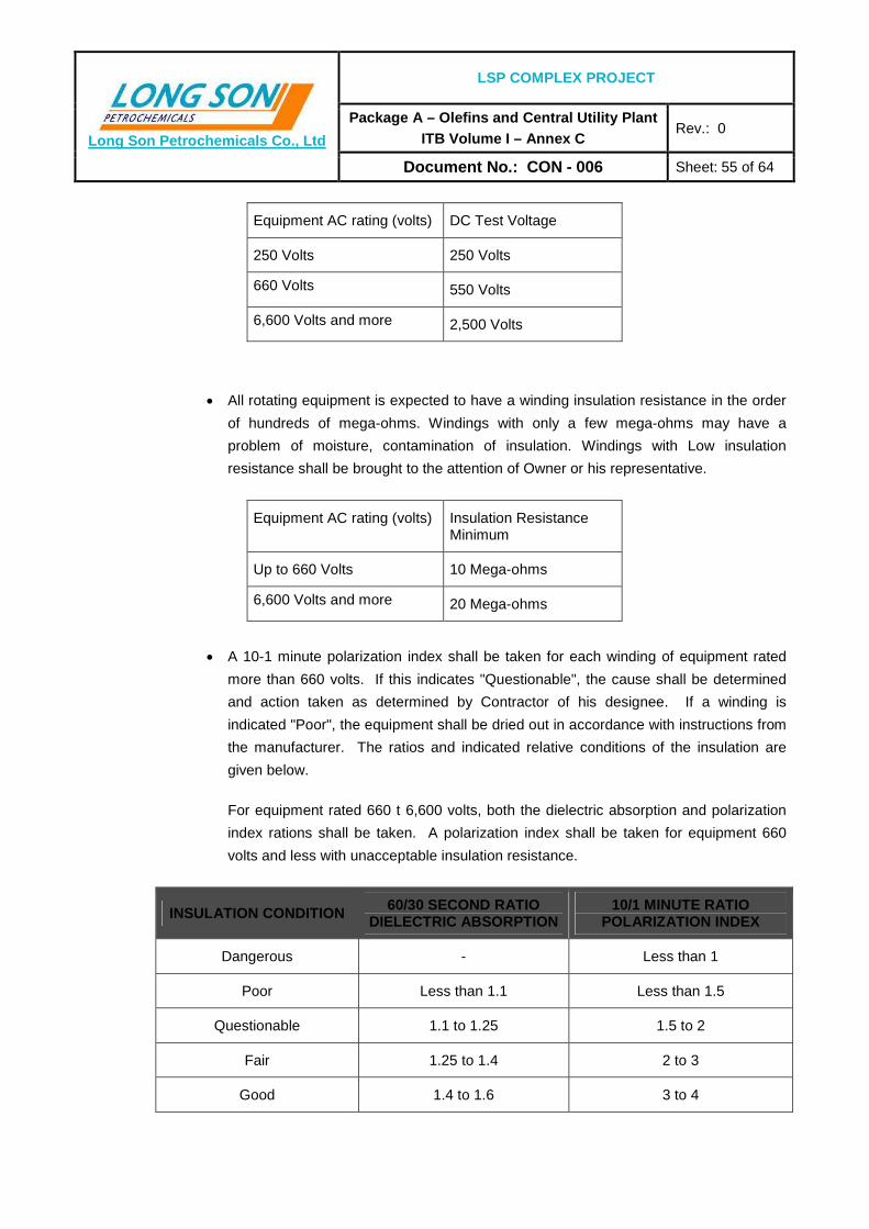
LSP COMPLEX PROJECT
Package A – Olefins and Central Utility Plant ITB Volume I – Annex C
Rev.: 0 Long Son Petrochemicals Co., Ltd
Document No.: CON - 006 Sheet: 55 of 64
Equipment AC rating (volts) DC Test Voltage
250 Volts 250 Volts
660 Volts 550 Volts
6,600 Volts and more 2,500 Volts
• All rotating equipment is expected to have a winding insulation resistance in the order
of hundreds of mega-ohms. Windings with only a few mega-ohms may have a
problem of moisture, contamination of insulation. Windings with Low insulation
resistance shall be brought to the attention of Owner or his representative.
Equipment AC rating (volts) Insulation Resistance Minimum
Up to 660 Volts 10 Mega-ohms
6,600 Volts and more 20 Mega-ohms
• A 10-1 minute polarization index shall be taken for each winding of equipment rated
more than 660 volts. If this indicates "Questionable", the cause shall be determined
and action taken as determined by Contractor of his designee. If a winding is
indicated "Poor", the equipment shall be dried out in accordance with instructions from
the manufacturer. The ratios and indicated relative conditions of the insulation are
given below.
For equipment rated 660 t 6,600 volts, both the dielectric absorption and polarization
index rations shall be taken. A polarization index shall be taken for equipment 660
volts and less with unacceptable insulation resistance.
INSULATION CONDITION 60/30 SECOND RATIO DIELECTRIC ABSORPTION
10/1 MINUTE RATIO POLARIZATION INDEX
Dangerous - Less than 1
Poor Less than 1.1 Less than 1.5
Questionable 1.1 to 1.25 1.5 to 2
Fair 1.25 to 1.4 2 to 3
Good 1.4 to 1.6 3 to 4

LSP COMPLEX PROJECT
Package A – Olefins and Central Utility Plant ITB Volume I – Annex C
Rev.: 0 Long Son Petrochemicals Co., Ltd
Document No.: CON - 006 Sheet: 56 of 64
Excellent Above 1.6 Above 4
• Equipment rated less than 660 volts with insulation resistance less than 1 mega-ohms
or insulation condition less than "fair" shall be dried out. Instructions for dry-out shall
be obtained from the equipment manufacturer.
• Equipment rated more than 6,600 volts or more than 5,000 kW or more than 5,000
kVA shall be subjected to a polarization index and a high direct voltage step test. The
procedure and criteria shall be in accordance with the recommended values
suggested by the manufacturers.
• In general, disconnect all capacitors and possible voltage sources from the
equipment. Maintenance tests can be run with the equipment feeder connected;
however, if unsatisfactory results are found, the feeder should be disconnected.
• All motors shall be run unloaded with the coupling disconnected for a period of at least 6
hours. During the running period, the motors shall be checked periodically for excessive
noise, current, speed, vibration or overheating of the bearing housing and motor frame.
• All rotating equipments shall be tested tan δ and power factor of stator winding test.
• Anti-condensation heater (if applicable) shall be tested.
• A check shall be made that space heaters are properly interlocked with the motor control
unit.
• Motors cannot be finally accepted until the equipment is energized during operational
tests.
• All motors shall be tested load run test and record the values of temperature, noise,
speed and vibration.
7.5.10. CABLES AND WIRES
• All cable connections must pass visual inspection for workmanship and conformance with
standard practices.
• All wires and cables shall be tested for continuity.
• All wires and cables shall be tested with a megger.

LSP COMPLEX PROJECT
Package A – Olefins and Central Utility Plant ITB Volume I – Annex C
Rev.: 0 Long Son Petrochemicals Co., Ltd
Document No.: CON - 006 Sheet: 57 of 64
• Lighting circuits and all general L.V. power services shall be tested during construction for
continuity, identification, and shall pass an operational test to see that the circuits perform
all functions for which they are designed.
Cables shall be visually inspected on the reels when received at the job site. Where
damage to metal-clad, metal-sheathed or shielded cables is suspected or indicated,
preliminary insulation tests shall be performed in accordance with the requirements of this
specification to determine that the cables are not less than those recommended by the
manufacturer. For nonmetallic sheathed and unshielded cables, special testing
arrangements may be necessary to proof-test cable insulation.
• Control wire and cables shall be checked by megger test, connections in accordance with
termination diagrams or tables, continuity of loops in accordance with elementary
diagrams and/or instrument loop drawings. All cables shall be identified in accordance
with appropriate tags on each end of the cable tested. The electrician shall attach a
temporary tag indicating the electrician's name and the date of testing the cable.
All solid-state devices shall be disconnected before megger tests are made.
• Test procedures - 380 volt service and less:
• Each 380 volt service cable from substations shall be meggered with the cable
connected to the open breaker in the racked position at the substation.
• Cables to individual motors shall be disconnected from motors for initial tests, and
followed by cables connected to motors.
• Cables to control centers shall be connected to the control center main breaker with
breaker in the open position during the test.
• Each phase shall be tested between conductor and ground and between phases,
except where the test includes windings, in which case the test may be applied
between all phases and ground.
• Minimum megger readings shall be:
10 mega-ohms for 380 volt services
5 mega-ohms for lower voltage services
� The megger test must be held until reading reaches a constant value. For 380 volt
cables, the megger test shall be held until three equal reading, each 1 minute apart,
are obtained.

LSP COMPLEX PROJECT
Package A – Olefins and Central Utility Plant ITB Volume I – Annex C
Rev.: 0 Long Son Petrochemicals Co., Ltd
Document No.: CON - 006 Sheet: 58 of 64
� A 1,000 volt motor-driven megger shall be used on all 380 volt cables and a 500 volt
motor driven megger shall be used on lower voltage cables.
• Test procedures for 6.6 kV cables and above:
� Each 6.6 kV cable from substations shall be tested with the cable connected to the
open breaker in the racked position at the substation.
� Cables to individual motors shall be disconnected from the motors for initial test, and
followed by tests on cables connected to motors.
� Cables to transformers shall be disconnected from transformer terminals but cable
termination shall be complete and intact. Testing shall not include any bus beyond the
pot-head or stress-cone terminations.
� All cable shall be tested between one (1) conductor and ground with the other two (2)
conductors and the metal sheath grounded to the same ground. Each conductor to be
tested in that manner.
� The dielectric absorption megger test shall be applied for duration long enough to fully
charge the cable. Megger readings shall be taken every 15 seconds during the first 3
minutes and at 1 minute intervals thereafter. The test shall continue until three equal
readings 1 minute apart are obtained. The cables should have approximately the
same megaohms reading. In the event that a cable shows an appreciably lower
resistance value than the others, it shall be brought to the attention of the Construction
Superintendent prior to application of the high-potential test.
� After an acceptable megger test, Contractor shall give the cables a high-potential test.
For metallic-armored, metallic-sheathed and metallic-shielded cables, the DC test
potential shall be 80 percent of the factory test voltage for 5 minutes. The test voltage
shall be applied gradually during the first minute, initial application being no greater
than rated. For unshielded nonmetallic jacketed cables, the test voltage shall not be
more than the rated voltage. All test values and results shall be in accordance with
IEC-Standards and the manufacturer's recommendations.
� The successful high-potential test shall be immediately followed by another megger
test as previously described.
� After completion of these tests, all conductors shall be discharged to ground.
� All cable which are pulled in duct bank or cable trench shall be tested tension during
pulling the cable and compare with the manufacture’s recommendation.

LSP COMPLEX PROJECT
Package A – Olefins and Central Utility Plant ITB Volume I – Annex C
Rev.: 0 Long Son Petrochemicals Co., Ltd
Document No.: CON - 006 Sheet: 59 of 64
7.5.11. BATTERY AND BATTERY CHARGER
• The following precautions should be taken before taking the battery in service:
� Check the battery cells for proper level of electrolyte, for specific gravity of electrolyte
by using a hydrometer, and for cracked jars.
� Check the cell connections and wiring for continuity and polarity.
� Check all protective devices for proper rating.
� Check the battery output voltage.
� All batteries shall be given a booster charge in accordance with the manufacturer's
instructions.
� Battery shall be discharged and recorded voltage, temperature, current and specific
gravity.
• Before energizing the battery charger, the battery should be connected across the output
terminal in such a manner that the positive battery terminal is connected to the positive
terminal of the charger. If the polarity of the battery terminals has been lost in a cable run,
a polarity check can be made pounding the AC supply switch to the charger and
connecting the battery leads to the output terminal of the charger. If it reads on scale, the
battery is connected correctly to the output terminal. It shall be verified that the battery
charger is delivering its maximum rated output.
• Chargers shall be tested in "Float" and “Equalizing” operation. Recorded Voltage in VDC
and Vrms at no-load and full load condition.
7.5.12. UNINTERRUPTIBLE POWER SYSTEMS (UPS)
• Preferably, an authorized manufacturer's representative should field-inspect and
commission uninterruptible power systems.
• In addition to routine inspection, the following minimum field checks and tests shall be
made:
� Adjustment of the battery charger for normal float and equalizing charge rates
including, as applicable, a check of the battery electrolyte or cell voltage.
� UPS shall be tested in “Float” and “Equalizing” operation. Record voltage and
waveform at no-load and full-load condition.

LSP COMPLEX PROJECT
Package A – Olefins and Central Utility Plant ITB Volume I – Annex C
Rev.: 0 Long Son Petrochemicals Co., Ltd
Document No.: CON - 006 Sheet: 60 of 64
� Short-circuit test to check the performance of the current-limit mode and, where
applicable, the operation of the transfer switch without loss of load.
� Transient-response tests, as applicable to the particular installation, including
measuring and recording the results.
� Simulation of all alarm conditions.
• For short-circuit and transient-response tests, equivalent test loads may be used when
the actual loads cannot be connected for test.
• Transient-response tests shall be made under the following conditions:
� Simulation of inverter failure and operation of the transfer switch without loss of load.
� Retransfer of full load to the inverter without loss of load.
� Simulation of a battery failure where facilities are provided to enable successful
inverter operation under this condition.
� Energization of the single largest inductive load or combination of loads which may be
energized simultaneously without loss of other operating loads.
7.5.13. EMERGENCY POWER
Emergency generation facilities shall be checked for automatic starting, generation and power
transfer during a simulated loss of voltage.
7.5.14. PACKAGED FACILITIES
• Where required or recommended by the manufacturer, special tests shall be performed to
confirm that equipment operation is in accordance with the intended service.
• Alarms for all electrical equipment shall be tested for proper operation by causing alarm
to sound under simulated abnormal conditions.
7.5.15. MISCELLANEOUS
• All other breakers, switches and conductor shall be given complete operational tests to
determine that all design functions are satisfactorily performed.

LSP COMPLEX PROJECT
Package A – Olefins and Central Utility Plant ITB Volume I – Annex C
Rev.: 0 Long Son Petrochemicals Co., Ltd
Document No.: CON - 006 Sheet: 61 of 64
• All switches (e.g. control, instrument, disconnect and safety), shall be inspected and
tested as to cleanliness and operation. Contacts, if so required, shall be cleaned before
operation.
• Switches shall be checked for correct sequence of operation. Fuses shall be inspected
for correct rating.
• Pressures, level, limit switches, etc. shall be inspected and tested in accordance with the
manufacture's recommendations. Adjustment shall be made so that switches will perform
the functions intended.
• Coordinate all testing of instruments for those devices.
• All bolts, which are held on bus bar, shall be measured torque. The values of torque shall
be compared with manufacture’s recommendations.
• All units, which are installed on the floor, shall be fixed with bolts in the floor.
7.5.16. EARTHING AND LIGHTNING SYSTEM
• Ground tests shall be accomplished with a proven instrument and shall include the
measurement of ground resistance at the following equipment items and structures:
� Medium high and low voltage switch gear
� All generators and motors
� Power transformer frames and neutral grounds
� Control Panels and consoles
� Panel boards
� Substation structures
� Lightning system components
� Equipotential bonding components
� Other miscellaneous grounds selected at random in a manner to be representative of
the entire installation.
• All connections shall be inspected before resistance measurement.
LSP COMPLEX PROJECT
Package A – Olefins and Central Utility Plant ITB Volume I – Annex C
Rev.: 0 Long Son Petrochemicals Co., Ltd
Document No.: CON - 006 Sheet: 62 of 64
• Ground resistivity test.
• Substation and plant ground system as a whole shall be tested using a four (4) terminal
Megger- Ground Tester on three occasions (with dry, normal, and wet ground conditions)
if possible.
• Each ground area shall measure less than 2.0 OHMS, ground resistance. Larger
substations and generating station areas shall measure resistance not to exceed 1 ohm.
Should higher resistance be obtained, existing ground rods shall be driven to a greater
depth by means of extensions or additional ground rods.
The final ground resistance measurement shall be taken with all grounds interconnected,
at which time the overall ground resistance shall be less than 2.0 ohms.
7.5.17. CAPACITOR BANK
All capacitors bank shall be tested and inspected as the following test and inspection, but not
limited to:
• All capacitors shall be inspected after installation and shall be checked for competence
with the following:
� Damage incurred in transportation.
� Check mounting for capacitors.
� Check that frame is grounded.
� No leakage of oil.
• Insulation resistance shall be one minute megger test and shall be recorded the values of
insulation resistance. The values of insulation shall be minimum as per table 1.
• In addition to the megger test, high potential test shall be performed. The sequence of
megger and high potential test shall be:
� Megger tests shall be made to determine the condition of insulation.
� The high potential test shall be applied only if the megger test passes minimum
requirements.
� The successful high potential test shall be followed immediately by another megger
test in order to detect any damage incurred by high voltage stresses.

LSP COMPLEX PROJECT
Package A – Olefins and Central Utility Plant ITB Volume I – Annex C
Rev.: 0 Long Son Petrochemicals Co., Ltd
Document No.: CON - 006 Sheet: 63 of 64
� All control, alarm and metering circuits shall be checked.
� The results of all tests shall be in accordance with the manufacture’s commendations.
� Resistor Discharge test.
7.5.18. METER AND TRANSDUCER
All meters and transducers shall be inspected before energizing and shall be calibrated after
energizing.
7.5.19. LIGHTING SYSTEM
• All lightings shall be inspected after installation and shall be checked for competence with
the following, but not limited to:
� All lighting shall be checked installation and compare with drawing.
� Damage incurred in transportation.
• In each area shall be tested illumination level. The values of illumination level shall refer
to specification.
• All lightings shall be energized for forty-eight (48) hours.

LSP COMPLEX PROJECT
Package A – Olefins and Central Utility Plant ITB Volume I – Annex C
Rev.: 0 Long Son Petrochemicals Co., Ltd
Document No.: CON - 006 Sheet: 64 of 64
8. MISCELLANEOUS ITEMS
All equipment, materials, infrastructure and other supplies not specifically mentioned in this
specification but forming part of Contractor’s Scope of Work/supply shall be tested and
inspected as follow
• Equipment, materials and supplies which can be allocated to any of the preceding shall
be tested and inspected as described therein.
• For equipment, materials and supplies, which cannot be allocated, the type and scope of
inspection and testing shall be specified by Contractor.
All above-mentioned equipment, materials and supplies shall be included in Contractor’s
Inspection Specification, without any cost to Owner.