Embed Size (px)
Citation preview

Computer Information System Department
New Jersey Institute of Technology Newark, NJ 07102
Human Machine Interface
In Partial Fulfillment of the Course Requirement for: CIS 490 – 001
Proposed to: Prof. Osama Eljabiri
Proposed by: Chang, Evelyn A.
Ding, Daniel Javier, Melissa Kim, Chiyong Pina, Glenys

Group 2
Page 2 of 94
TABLE OF CONTENTS
Page i. Title Page
ii. Table of Contents 2
1. Introduction 5
1.1 Project Initiation
1.1.1 Project Abstract 5
1.1.2 History 6
1.2 Project Planning
1.2.1 Background 7
1.2.2 Problem Statement 7
1.2.3 Previous Works 11
1.2.4 Methodologies
1.2.4.1 Waterfall Model 13
1.2.4.2 Spiral Model 15
1.2.4.3 Extreme Programming (XP) – Agile Approach 17
1.2.4.4 WINWIN Spiral Model 19
1.2.4.5 Methodology Selection Matrix 20
1.2.5 Glossary 21
2. Project Management
2.1 Project Team and Roles 27
2.2 Resources Management
2.2.1 Work Breakdown Structure (WBS) 28
2.2.2 Project Milestones 30
2.2.3 Preliminary Project Plan 31
2.2.4 Baseline Plan 32

Group 2
Page 3 of 94
2.3 Feasibility Study: Feasibility Study
2.3.1 Economic Feasibility 33
2.3.2 Feasibility Analysis 34
2.3.3 Break-Even Point Analysis 35
2.4 Risk Management 36
3. Project Analysis
3.1 Stakeholder Identification 40
3.2 Gathering Requirements 42
3.2.1 Interviewing 42
3.2.2 USE-CASE Scenarios 43
3.2.3 Brainstorming 50
3.3 Documenting Requirements
3.3.1 Functional Requirements 53
3.3.2 Non-Functional Requirements 55
3.4 Modeling Requirements
3.4.1 USE-CASE Diagram 56
3.4.2 DFD Diagrams 57
3.4.2.1 Grammatical Analysis 59
3.4.2.2 Context Diagram 59
3.4.2.3 General Context Diagram 60
3.4.2.4 Decompositions 61
3.4.3 Data Dictionary 69
4. System Specifications
4.1 Requirement Specification 72
4.1.1 Structured English 72
4.1.2 Decision Trees 74
4.1.3 Decision Tables 75

Group 2
Page 4 of 94
4.2 Functional Specification 76
4.3 Design Specification 77
5. Qualifications
5.1 Installation Qualification 78
5.2 Operational Qualification 80
5.3 Performance Qualification 81
6. System Design
6.1 Structured Chart 83
6.2 User Interface Design
6.2.1 AS-IS User Interface Design 84
6.2.2 TO-BE User Interface Design
6.4 Database Design
6.4.1 AS-IS Database Design 87
6.4.2 TO-BE Database Design 89
7. System Architectural Model
7.1 AS-IS System Architectural Model 90
7.2 TO-BE System Architectural Model 91
8. References 92
9. Extra Work 94

Group 2
Page 5 of 94
1. Introduction
1.1 Project Initiation
1.1.1 Project Abstract
This project is concerned with the new approach to developing user-interface
applications based on the cognitive aspects of human information processing. Our team
consists of five members whom will assist the engineers of ABC Laboratories in the
development of this Human Machine-Interface (HMI) with ISQL database software.
Our project will provide operators of the facility the ability to monitor and control
equipments from their personal computer platforms. The application interface animates the
manufacturing process on computer displays for engineers to facilitate the monitoring of the
drug production. Equipment operations and functions for manufacturing products are easily
controlled by the “click of a mouse.” Thus, the HMI system should be user-friendly.
This new technology offers engineers the opportunity to increase operating efficiency
and reduce operating costs by allowing the remote monitoring and control of water and
wastewater treatment plants, treatment processes, wells, ground storage tanks, and pumping
stations. Using HMI technology, one person can monitor in real time, multiple facilities located
in geographically dispersed areas. The previous database will be updated to higher version with
better performance and with advance features.

Group 2
Page 6 of 94
1.1.2 History
The Human-Machine Interface (HMI) was originated from man-machine interface (MMI)
of the 1950’s, followed by the Programmable Logic Controller (PLC) in the 1970’s. Personal
computer (PC) was developed in the early 1980’s. HMI was created from pixel graphics to
highly graphical object-oriented application. This object-oriented application animates a
production process that provides the look and feel of chart recorders and strip recorders.
The design engineers began creating software-based process visualizations that provide
much more graphical views of production processes. The production process is controlled by
the PLC. This visualization is called HMI. The HMI talks to the PLC and reads its data to
populate the highly graphical screens. The screen provides animation and colors that imitates
the process and showed the real-time data on-screen to provide better feedback to operators.
The architectural concept of HMI development is to normalize plant data into simple tag
data types and abstract graphical user interface (GUI) component. There are available I/O
driver toolkit to support multiple PLCs and provides a unified interface to connect various PLC
drivers. This actually means that HMI became independent of factory-floor devices and was
able to connect to hundreds of different devices.

Group 2
Page 7 of 94
1.2 Project Planning
1.2.1 Background
ABC Laboratories is continuously improving its manufacturing practices to meet the
stringent requirements of the FDA. In their engineering department, engineers are trying to
develop a multiple front-end interface system (HMI) and a strong back-end server with
database program (ISQL) to facilitate the manufacturing of drugs and medication. This
program, if successful, would greatly enhanced the manufacturing process by reliably
monitoring the synthesis of medications. Monitoring is an important task that is detrimental in
terms of safely producing a drug.
Dr. J.P. Gray and W.W. Fred founded P Pharma L.P. and The P. Fred Company. They
started the company on Manhattan's Lower East Side on 1892. P Pharma L.P. is one of the
fastest-growing pharmaceutical companies in the world. The company progressed and
expanded their territories to One Stamford Forum, a distinctive, tiered office tower in
Stamford, CT, 13-story, 529,000-square-foot building houses more than 1,000 employees. ABC
Laboratories is a manufacturing division that was established on 1976 in Totowa, NJ. They have
two separate research facilities in the United States that is in Ardsley, NY and Cranbury, NJ.
They have additional headquarters and manufacturing plants that are located in Secaucus, NJ,
Norwalk, CT, Wilson, NC, Garrett Mt, NJ, and Canada. P Pharma L.P., The P Fred Company, and
associated companies are part of an international group of privately held associated companies
- including Mundipharma Vertriebsgesellschaft mbH in Germany and Napp Pharmaceuticals
Limited in the U.K. - employing approximately 5,000 people in pharmaceutical research,
manufacturing, and marketing worldwide.
However, in order for them to maintain their excellent standing, they concentrate their
concerns in their manufacturing division, such as ABC Laboratories. ABC Laboratories
manufactures narcotic and non-narcotic drugs. These products include OxyContin® (oxycodone
HCl controlled-release) Tablets, MS Contin® (morphine sulfate controlled-release) Tablets,

Group 2
Page 8 of 94
Uniphyl® (theophylline, anhydrous) Tablets, Chirocaine® (levobupivacaine injection), and the
popular over-the-counter Senokot® Laxatives, Betadine® Microbicides, and Betadine® Brand
Antibiotics. In the process of making these drug products, the trained operators in the facility
has the privilege to interact with the HMI system to control and monitor the cycle of drug
productions in an equipment. The application interface animates the manufacturing process on
computer displays for operators to facilitate the monitoring of the drug production. Instead of
running the equipment manually, which is considered hazardous, the interface system is
programmed to perform an operation with the convenience of touch screen interface.
Nevertheless, the process of controlling gigantic equipment has few issues that the current
system is in deep concerns.
The most common concern is that the built-in interface of the equipment is too complex
for non-technical users. The equipment installed in the facility has its system requirements not
complying with the requirements of the ABC Laboratories. Hence, the interface of the
equipment is not a user-friendly.
Creating batch report is one of the current issues of the engineers in the ABC
Laboratories. The current version of the database, which is Industrial SQL (ISQL) Server 7.1, is
not designed to generate report. The reporting option of a standard database is not available in
the current ISQL because a standard database does not have the ability to handle massive
real-time data in every millisecond. The way the ISQL was designed is for collecting enormous
and rapid incoming data from the PLC. It also has the ability to compress Giga bytes of data in
every ~8 seconds.
The automation of equipments in the facility offers the engineers the opportunity to
increase operating efficiency and reduce operating costs by allowing the remote monitoring and
control of water and wastewater treatment plants, treatment processes, wells, ground storage
tanks, and pumping stations. Using HMI technology, one person can monitor in real-time,
multiple facilities located in geographically dispersed areas.

Group 2
Page 9 of 94
1.2.2 Problem Statement
Although the existing HMI system is functional, the current User Interface is too
complex and non-intuitive for non-technical users. These users who operate the systems don’t
understand the technical diagrams and the components in the current system. Furthermore,
they are intimidated to use the system due to this lack of understanding. More intuitive
indicators for parameters or slider bars with warning indicators will help non-technical users
monitor every component of the system and ensure that they know what the appropriate
values for each parameter are.
Current users requested more effective and user-friendly ergonomics. The clients
described that the interface should be intuitive enough even a non-technical person can
operate the system with just enough information about what each parameter should be. In the
case if a regular operator is absent for any reason his or her substitute can easily operate the
system with little training.
For any experienced software developer, the practice of using meaningful and consistent
naming conventions in their code should be second nature. It helps themselves as well as
others to better understand what was written. The current customized code written by the
vendor is too cryptic and lacks proper documentation. The system developers spent a lot of
unnecessary time trying to figure out what was written. If the code was commented properly a
lot of time could be saved for other tasks. For effective and efficient development of the current
project as well as future maintenance and upgrades, the current code has to be made more
concise and understandable. More code comments are required. Although the system is object
oriented. Some classes and modules still need to be optimized and changed in the future to
tailor to the hardware and infrastructure changes. Therefore it is important that the time is
spent right now to optimize and properly document the code so in the future time and money
can be saved when upgrades are necessary.

Group 2
Page 10 of 94
There was an instance where a local administrator of a particular HMI module was able
to delete the system administrator of the entire system. Part of the system was rendered
inoperable for that reason. A system restore had to be carried out to return the system to a
previous state. The permissions for each security role in the current system has to be checked
and reapplied carefully so that each user will have only the privileges he or she is supposed to
have.
The physical location of the hardware for the HMI system will also be a concern.
Currently some of the more sensitive hardware such as the terminals is located near potentially
hazardous production areas. Careful Analysis has to be performed to move them to a safer yet
in a strategic location.
One important business process is report generation from historical plant data. The
current HMI system does not have a dedicated reporting module. Microsoft Access is used via
open database connectivity to ISQL and ad hoc reports are then generated within Access.
Microsoft Access was designed as a single user database and does not handle large amounts of
plant data well. It takes up to two days to generate a typical report and that is not acceptable
to the clients. The request is to develop a dedicated reporting module for the HMI system so
report generation is dynamic and relatively fast.

Group 2
Page 11 of 94
1.2.3 Previous Works There are many developers of HMI application. Some developers based their application
on pixel graphics and some based on Object-Oriented programming. The graphic application is
tremendously difficult to program pixel drawings and screen diagrams. The developers soon
are trying to establish to design images and diagrams through Object-Oriented designs. In
comparison, all the interface products have similar problems:
The first system is the InTouch® produced by Wonderware Inc., the world's leading HMI
software company. InTouch® provides a single, integrated view of all control and information
resources. It enables engineers, supervisors, managers and operators to view and interact with
the workings of an entire operation through graphical representations of their production
processes. But, the User Interface is too complex and non-intuitive for non-technical users.
Information on the InTouch® may be found at the following URL:
http://www.wonderware.com/products/visualization/intouch/
Second system is the OI-2000® HMI Software produced by Software Horizons Inc. OI-
2000® is powerful, easy to use, yet cost effective HMI available for industrial monitoring and
reporting. It has fast screen creation process through support for OLE (object linking and
embedding), and has TCP/IP Connectivity enables multiple systems to be linked together and
share data. It also has macros and script programming functionalities allow data manipulation
and decision making for user’s application needs.
Information on the OI-2000® may be found at the following URL:
http://www.shorizons.com/
The last system is the Visual Tag System (VTS) produced by Trihedral Engineering. VTS
provides software tools to develop operator interfaces for Original Equipment Manufacturers
(OEMs), Systems Integrators (SIs) and advanced end users across all types of industry. It even
gives users the tools to create new tools to tackle specific situations, and create a custom
operator interface software package with its own personality.

Group 2
Page 12 of 94
Information on the VTS® may be found at the following URL:
http://www.trihedral.com/html/about_trihedral/about_trihedral.html

Group 2
Page 13 of 94
1.2.4 Methodologies
1.2.4.1 Waterfall Model
The approach we are going to use for the SDLC (Systems Development Life Cycle) of
our system is the classic waterfall model. It involves six major phases each dependant on it’s
predecessor:
Step one involves project identification and selection. Priorities for systems and
projects are identified. An overall architecture for all system components is the result of this
planning phase.
Step two involves project initiation and planning. Detailed steps and work plan for the
project is defined. Specifications for high-level system requirements and features are finalized
here. Resource planning and system justification of the business case is also completed.
Step three is the analysis phase. An overview of the current system is created and the
problem and opportunities are explored. Recommendations are made to replace, repair or
enhance the current system. Justifications are made for the intended alternative.
Step four is the Design phase. The design face itself is divided into two sub-phases.
First, the logical design phase. Functional and detailed specifications of all system components

Group 2
Page 14 of 94
are defined. This includes data, processors, inputs, and outputs. Secondly is the physical
design phase. This is where technical, detailed specifications of all system components are
specified. These include programs, files, network, system software, etc.
Step five is the implementation phase. This is the actual development phase where
code, documentation, training procedures, and support capabilities are implemented.
Step six is the maintenance phase. Bug fixes, new versions or releases of software and
associated updates to documentation, training and support are applied in this phase.
Although these major phases cannot be implemented concurrently. Sub-phases within
these major phases can occur concurrently where applicable.

Group 2
Page 15 of 94
1.2.4.2 Spiral Model
The idea of the spiral model is evolutionary development intended to help manage risks,
using the waterfall model for each step. The developers usually only define the highest priority
features first rather than the details of the entire system. Once the high priority features are
defined and implemented, feedback from the users or customers are collected. With the
knowledge collected, the developers can go back to the system to define and implement more
features in greater details. In its original form, the spiral model is consisted of four phases.
• Planning (objectives, constraints, alternatives)
• Risk Analysis
• Engineering
• Evaluation
Each phase is represented as a quadrant of the spiral model. Each phase will be
revisited and through the successive iterations of these phases, the project follows the path
of the spiral.

Group 2
Page 16 of 94
Initially the project objectives and requirements are defined, and then risk analysis is
performed to determine the volatility and level of uncertainty of the project requirements.
Prototyping is then used in the engineering phase to build a mock up version of the
application. The customer will evaluate this prototype and a more concrete requirement
can be obtained from the feedback of this evaluation.
At the conclusion of each spiral, a decision must be made as to whether it's feasible to
continue the project. If a decision were made to carry on the project, the spiral would
progress through to the next iteration, where the four phases are revisited into a more
detailed system. More and more functionality is built into the application through the
successive builds. A close to complete system should be produced by the time the spiral
has reached its third level.
Strengths of Spiral Model:
• Introduces formal risk management to the software engineering process
• Prototyping controls cost (Sorensen, Acosta), and coveys to the user the look
and feel of a system far more thoroughly than a requirements specification
(Boehm, 1996)
• Evolutionary development allows a product to be released for evaluation early,
and seeks to provide feedback and evaluation for the development team.
Weaknesses of Spiral Model:
• Lack of risk management experience (Charette)
• Lack of milestones (Microsoft, Boehm)
• Management is dubious of the spiral process, its evolutionary nature (May), and
the concept of starting a project without rigidly defined objectives (Sorensen).

Group 2
Page 17 of 94
1.2.4.3 Extreme Programming (XP) – Agile Approach
The Agile approach to software development focuses on fast delivery of quality products
through which the project life cycle can be reduced. Agile principles include but are not limited
to a) customer satisfaction through early and continuous delivery of product; b) allow
requirement changes at any stages of the development process for customer advantage; c)
provide customer with frequent working-product delivery allowing testing and viewing how the
product will perform and looks; d) developers and customers ‘must work daily through the
project’; and e) ‘working software is the primary measure of progress’.
Extreme Programming (XP) is an agile methodology which focuses in team work,
customer satisfaction and fast delivery of needed product. “XP improves a software project in
four essential ways: communication, simplicity, feedback and courage”. XP allows changing
customer requirements at any stage of the development life cycle. The product is delivered to
the customer as early as possible, making it easier to implement any changes in requirements.
The team roles in XP are Developers, Customers, and Management.
XP Practices include:
1. Planning Game: there is a close interaction between the programmers and the
customer to estimate the effort needed for implementation (programmers) and
scope and timing of releases (Customer)
2. Frequent Small Releases: release system as often as possible
3. On-site Customer: customer has to be present and available full-time for the
team
4. Testing: test and run system continuously
5. Simple Design: design simplest possible solution that is implemental at the
moment; avoid complexity, extra/duplicate code
6. Re-factoring: improve design of existing code by removing duplication, improving
communication, simplifying and adding flexibility

Group 2
Page 18 of 94
7. Pair Programming: two people get to develop all code concentrating on the same
task; one person focuses on the task at hand ‘driving’, and the other focuses on
the big picture ‘navigating’
8. Collective Code Ownership: any team member can change the code
9. Continuous Integration: code is added as soon as it is ready
10. Coding Standards: programmers must follow the coding rules; emphasizes
communication through the code
11. Metaphor: system is defined by a metaphor/set of metaphors between the
customer and programmers, which guide all development by describing how the
system works
12. 40-hour Week: a maximum of 40-hour working week. No two overtime weeks
in a row are allowed
Every development process is different from one another. When using XP methodology,
not all practices have to be selected. Practices should be tailored to suit the needs of the
individual project.

Group 2
Page 19 of 94
1.2.4.4 The WINWIN Spiral Model
The WINWIN spiral methodology expands the Boehm-Spiral methodology by adding a
priority-setting step called the WINWIN Process at the beginning of each spiral cycle and by
adding intermediate goals, called anchor points. The WINWIN spiral methodology defines a set
of negotiation activities at the beginning of each pass around the spiral.
These activities include identifying the system or subsystem’s stakeholders, determining
the stakeholders’ “win conditions” and the negotiation of the stakeholders’ win conditions to
convert them into the project’s set of win-win conditions. A ‘win condition’ implies that the
customer wins by getting the system, which satisfied his/her needs, and the developer wins by
finishing the project on time, on target, and on budget.
The three anchor points view the project progress as the project traverses through the
spiral, Life Cycle Objectives (LCO), Life Cycle Architecture (LCA), and Initial Operational
Capability (IOC). LCO, the first anchor point, defines the business case for the entire system.
It establishes the why, what, when, who, where, how, and cost of the system. LCA, the second
anchor point, defines the life cycle architecture. IOC, the third anchor point, defines the
operational capabilities of the system.

Group 2
Page 20 of 94
1.2.4.5 Methodology Selection Matrix
MODEL CRITERIA
Waterfall
Spiral
XP
WINWIN
Spiral
20 Project Integration 15 15 10 20 10 Speed 15 20 25 20 15 Quality Management 25 20 25 20 10 Risk Management 15 15 20 20 10 Focus on Avoiding Errors 15 20 20 20 10 Focus on Project Maintenance 25 20 10 20 10 Ability to Manage Change 15 20 20 20 15 Iterative Nature 20 20 25 20 100 145 150 155 160
Methodology Selection
We researched a number of methodologies that we can incorporate into our HMI
Project. After researching four various methodologies, we chose to adopt the WINWIN Spiral
as our project development methodology. We took into consideration other methodologies
including, Waterfall, Spiral, and Extreme Programming. After establishing our project criteria,
we designed a Methodology Selection Matrix system to evaluate the researched methodologies
and obtain the one that best suit our project goal. The Matrix assessed all the different
methodologies against the criteria that we provided, giving WINWIN Spiral the highest points
on the matrix.

Group 2
Page 21 of 94
1.2.5 Glossary
CFM - Cubic-foot per Minute
DFD – Data Flow Diagram
ER-D – Entity-relationship Diagram
GUI – Graphical User Interface
HMI – Human Machine Interface
IOC - Initial Operational Capability
I/O - Input/Output
IQ - Installation Qualification
ISQL – Industrial Structured Query Language
LCA - Life Cycle Architecture
LCO - Life Cycle Objectives
MMI – Man Machine Interface
OEMs - Original Equipment Manufacturers
OLE - Object Linking Embedding
OQ - Operational Qualifications
PC – Personal Computer
PLC – Programmable Logic Controller
PQ - Performance Qualification
SDLC – Systems Development Life Cycle
SI - Systems Integrators
TCP/IP – Transmission Control Protocol or Internet Protocol
VTS – Virtual Tag System
XP - Extreme Programming
Abstract - the degree to which a system or component performs only the necessary functions
relevant to a particular purpose.

Group 2
Page 22 of 94
Ad hoc - contrived purely for the purpose in hand rather than planned carefully in advance.
Analysis - a set of activities that attempt to understand and model customer needs and
constraints.
Architectural design - the process of defining a collection of hardware and software
components and their interfaces to establish the framework for the development of a
computer system.
Authentication - the verification of the identity of a person or process.
Baseline - a point at which some deliverable produced during the software engineering
process is put under formal change control.
Brainstorming - the unrestrained offering of ideas or suggestions by all members of a
committee, conference, etc. in an effort to find a solution to a problem and generate fresh
ideas
CAT 5 - Short for Category 5, network cabling that consists of four twisted pairs of copper wire
terminated by RJ45 connectors. Cat-5 cabling supports frequencies up to 100 MHz and
speeds up to 1000 Mbps. It can be used for ATM, token ring, 1000Base-T, 100Base-T, and
10Base-T networking.
Compliant - ready to conform or agree to do something.
Components - is an identifiable part of a larger program or construction. Usually, a
component provides a particular function or group of related functions.
Complexity - (Apparent) the degree to which a system or component has a design or
implementation that is difficult to understand and verify.
-(Inherent) the degree of complication of a system or system component, determined by
such factors as the number and intricacy of interfaces, the number and intricacy of
conditional branches, the degree of nesting, and the types of data structures.
Concurrent – happening together: taking place or existing at the same time, or running
parallel.
Constraints - are restrictions or limitations placed on requirements or design.

Group 2
Page 23 of 94
Context Diagram – An overview of an organizational system that shows the system
boundaries, external entities that interact, with the system, and the major information
flows between the entities and the system.
Cryptic – Having an ambiguous or hidden meaning.
Data flow diagram (DFD) - a modeling notation that represents a functional decomposition
of a system
Data Dictionary - a database that contains definitions of all data items defined during analysis
Database - a collection of logically related data stored together in one or more computerized
files.
Database Design - the process of developing a database that will meet a user's requirements.
The activity includes three separate but dependent steps: conceptual database design,
logical database design, and physical database design.
Ergonomics – The applied science of equipment design intended to reduce operator fatigue
and discomfort.
Feasibility – the degree to which something can be carried out or achieved. The analysis of a
problem to determine if it can be solved effectively. The operational (will it work?),
economical (costs and benefits) and technical (can it be built?) aspects are part of the
study.
Flexibility - the ease with which a system or component can be modified for use in
applications or environments other than those for which it was specifically designed.
Gantt Chart – A graphical representation of a project that shows each task as a horizontal bar
whose length is proportional to its time for completion.
Graphics – methods and techniques for converting data to or from graphic display via
computers.

Group 2
Page 24 of 94
Hardware - the physical, touchable, material parts of a computer or other system
Implementation - is the carrying out, execution, or practice of a plan, a method, or any
design for doing something. Implementation is the action that must follow any preliminary
thinking in order for something to actually happen.
Integration - the specific approach to integration testing
Integration testing - a testing step that constructs the software while testing it
Interface - the point of interaction or communication between a computer and another entity.
Interface design - the activity concerned with the interfaces of the software system
contained in the software requirements and software interface requirements
documentation. Consolidates the interface descriptions into a single interface description of
the software system.
Milestones - a point in time that is used to indicate progress during a project
InTouch - the first object-oriented software based on Windows for the plant floor.
Intuitive –known directly and instinctively, without being discovered or consciously perceived.
Iteration - repetition of a sequence of instructions.
Metaphor - the application of a word or phrase to somebody or something that is not meant
literally but to make a comparison.
Milestones – a point in time that is used to indicate progress during a project
Mind mapping - storing information in a pattern that one understands to separate and use
when necessary.
Mired - a troublesome or oppressive situation or state that is very difficult to escape from.
Module - An independent piece of software, which forms part of one or more larger programs.
Object-Oriented Programming - a unique instance of a data structure defined according to
the template provided by its class. Each object has its own values for the variables
belonging to its class and can respond to the messages defined by its class.
Optimize - to find the best possible solution to a technical problem in which there are a
number of competing or conflicting considerations

Group 2
Page 25 of 94
Pert Chart – A diagram that depicts project tasks and their interrelationships; PERT stands for
Program Evaluation Review Technique.
Pixel - the smallest resolvable rectangular area of an image, either on a screen or stored in
memory.
Process – the sequence of states of an executing program.
Project Manager – systems analyst with a diverse set of skills—management, leadership,
technical, conflict management, and customer relationship—which is responsible for
initiating, planning, executing, and closing down a project.
Project Plan - a description of the management approach for a project
Project risks - the set of potential project problems or occurrences that may cause the project
to fail
Project scope - a statement of basic requirements of the software to be built
Proprietary - implies a product imbued with exclusive magic by the unmatched brilliance of
the company's own hardware or software designers.
Prototyping – The creation of a model and the simulation of all aspects of a product.
Reliability - the ability of a system or component to perform its required functions under
stated conditions for a specified period of time.
Security – the ability of a system to manage, protect, and distribute sensitive information.
Specification - A document describing how some system should work.
Software – The instructions executed by a computer, as opposed to the physical device on
which they run.
System – any collection of component elements that work together to perform a task. In
computer science, system is used in a variety of contexts. A computer is hardware system
consisting of a microprocessor and allied chips and circuitry, plus an input device
(keyboard, mouse, disk drive), an output device (monitor, disk drive), and any peripheral
devices (printer, modem).

Group 2
Page 26 of 94
Traceability - the degree to which a relationship can be established between two or more
products of the development process, especially products having a predecessor-successor
or master-subordinate relationship to one another
TCP/IP - the connection-oriented protocol built on top of Internet Protocol (IP) and is nearly
always seen in the combination TCP/IP (TCP over IP).
Use Case - is a description of an interaction between an actor and a system.
Volatility - characterized by or prone to sudden change. COMPUTING - losing data when power is
off: used to describe a computer memory that does not store data when the power is
turned off. Random access memory RAM is volatile, while read-only memory ROM is not.
Work breakdown structure (WBS) - the set of work tasks required to build the software;
defined as part of the process model.

Group 2
Page 27 of 94
2. Project Management
2.1 Project Team and Roles
Member Name
Role
Responsibilities
Evelyn Chang
Project Manager,
Front-End Designer
Distributing tasks among team members Interview & Communicate with the Sponsor and
system stakeholders Designing the Front End Interface Assisting other members in their assigned tasks
Ding Daniel
Database Designer
Designing/enhancing the AS-IS system database ER-Model Problem Statement Methodologies
Melissa Javier
System Analyst
Working in gathering and modeling requirements Risk Management analysis Use Case Scenario Use Case Diagram
Chiyong Kim (John)
System Analyst
Working together with Melissa in gathering and collecting requirements
Data Flow Diagrams Data Dictionary Requirement Specifications Structured Chart
Glenys Pina
Assistant Project Manager
Assisting Project manager as well as other team members in performing their tasks
Working as a global resource within our group Feasibility Studies Resource Management Gathering and modeling requirements Methodologies

Group 2
Page 28 of 94
2.2 Resources Management
2.2.1 Work Breakdown Structure (WBS)
Work Breakdown Structure
Duration
(Days)
Start
Finish
Resources
1. Introduction 15 09/25/02 10/11/02 1.1 Project Initiation 09/25/02 09/28/02 1.1.1 Interview Sponsor 09/25/02 09/25/02 Evelyn Chang 1.1.2 Project Scope 09/25/02 09/27/02 All Members 1.1.3 History 09/25/02 09/28/02 Evelyn Chang 1.2 Project Planning 09/29/02 10/11/02 1.2.1 Background 09/29/02 10/02/02 Evelyn Chang 1.2.2 Problem Statement 09/29/02 10/03/02 Daniel Ding 1.2.3 Previous Works 09/29/02 10/04/02 Chiyong Kim
Melisa Javier 1.2.4 Methodologies 10/03/02 10/10/02 Daniel Ding
Glenys Pina 1.2.4.1 Methodology Method Selection Matrix
10/10/02 10/10/02 Daniel Ding Glenys Pina
1.2.5 Glossary 10/11/02 10/11/02 All Members 2. Project Management 10 10/12/02 10/21/02 2.1 Project Team and Roles 10/12/02 10/13/02 Evelyn Chang
Glenys Pina 2.2 Resources Management 10/13/02 10/16/02
2.2.1 Work Breakdown Structure 10/13/02 10/14/02 Evelyn Chang Glenys Pina
2.2.2 Project Milestones 10/15/02 10/16/02 Glenys Pina 2.2.3 Preliminary Project Plan (GANTT Chart)
10/16/02 10/16/02 Evelyn Chang Glenys Pina
2.2.4 Baseline Plan (PERT Chart) 10/16/02 10/16/02 Glenys Pina 2.3 Feasibility Study 10/17/02 10/19/02 Glenys Pina 2.3.1 Economic Feasibility 10/17/02 10/18/02 Glenys Pina 2.3.2 Feasibility Analysis 10/17/02 10/19/02 Glenys Pina 2.3.3 Break Even Analysis 10/19/02 10/19/02 Glenys Pina 2.4 Risk Management 10/20/02 10/21/02 Evelyn Chang
Melisa Javier 3. Analysis 30 10/22/02 11/28/02 3.1 Stakeholder Identification 10/22/02 10/23/02 Evelyn Chang 3.2 Gathering Requirements 10/24/02 11/08/02 3.2.1 Interviewing 10/24/02 11/08/02 Daniel Ding 3.2.2 USE-CASE Scenarios 10/24/02 11/08/02 Evelyn Chang
Melisa Javier Glenys Pina
3.2.3 Brainstorming 10/24/02 11/08/02 Daniel Ding 3.2.4 Mind Mapping 10/24/02 11/08/02 Daniel Ding

Group 2
Page 29 of 94
3.3 Documenting Requirements 11/09/02 11/12/02 3.3.1 Functional Requirements 11/09/02 11/12/02 Evelyn Chang 3.3.2 Non-Functional Requirements 11/09/02 11/12/02 Evelyn Chang 3.4 Modeling Requirements 11/14/02 11/28/02 3.4.1 USE-CASE Diagram
11/14/02
11/21/02
Evelyn Chang Melisa Javier Glenys Pina
3.4.2 DFD Diagram 11/14/02 11/21/02 3.4.2.1 Grammatical Analysis 11/14/02 11/21/02 Chiyong Kim 3.4.2.2 Context Diagram 11/14/02 11/21/02 Chiyong Kim 3.4.2.2.1 AS-IS Context Diagram 11/14/02 11/21/02 Chiyong Kim 3.4.2.2.2 TO-BE Context Diagram 11/14/02 11/21/02 Chiyong Kim 3.4.2.3 General Context Diagram 11/14/02 11/21/02 Chiyong Kim 3.4.2.4 Decompositions 11/14/02 11/21/02 Chiyong Kim 3.4.3 Data Dictionary 11/22/02 11/28/02 Chiyong Kim 4. Requirement Specification 12 11/14/02 11/28/02 4.1 Structured English 11/14/02 11/28/02 Chiyong Kim 4.2 Decision Trees 11/14/02 11/28/02 Chiyong Kim 4.3 Decision Tables 11/14/02 11/28/02 Chiyong Kim 5. Qualification 7 11/21/02 11/28/02 5.1 Performance Qualification 11/21/02 11/28/02 Evelyn Chang 5.2 Operational Qualification 11/21/02 11/28/02 Evelyn Chang 5.3 Installation Qualification 11/21/02 11/28/02 Evelyn Chang 6. System Design 9 11/22/02 12/03/02 6.1 ERM Model 11/22/02 12/03/02 Daniel Ding 6.2 Structured Chart 11/22/02 12/03/02 Chiyong Kim 6.3 User Interface Design 11/22/02 12/03/02 6.3.1 AS-IS User Interface Design 11/22/02 12/03/02 Evelyn Chang
Glenys Pina 6.3.2 TO-BE User Interface Design 11/22/02 12/03/02 Evelyn Chang 6.4 Database Design 11/22/02 12/03/02 6.4.1 AS-IS Database Design 11/22/02 12/03/02 Daniel Ding 6.4.2 TO-BE Database Design 11/22/02 12/03/02 Daniel Ding 7. System Architectural Model 9 11/22/02 12/03/02 7.1 AS-IS Architectural Model 11/22/02 12/03/02 Evelyn Chang 7.2 TO-BE Architectural Model 11/22/02 12/03/02 Evelyn Chang

Group 2
Page 30 of 94
2.2.2 Project Milestones
PHASE (DATE) PHASE IMPLEMENTED
START END
ALLOCATED RESOURCES
PHASE DESCRIPTION
PHASE IA– Introduction
09/25/02 09/28/02
Evelyn Chang Daniel Ding Chiyong Kim Melissa Javier Glenys Pina
The following tasks were completed during this phase, Interviewing Project Sponsor, Project Scope, and History
PHASE IB - Project Planning
09/29/02 10/11/02
Evelyn Chang Daniel Ding Chiyong Kim Melissa Javier Glenys Pina
The following tasks were completed during this phase, Background, Problem statement, Previous work, Methodologies and glossary
PHASE IIA - Project Management
10/12/02 10/21/02 Evelyn Chang Glenys Pina
The following tasks were completed during this phase, Project Team and Roles, WBS, Project Milestones, Preliminary Project Plan, Baseline Plan
PHASE IIB - Project Management
10/17/02 10/21/21 Evelyn Chang Melissa Javier Glenys Pina
The following tasks were completed during this phase, Feasibility Studies, and Risk Management
PHASE IIIA – Analysis
10/22/02 11/08/02
Evelyn Chang Daniel Ding Melissa Javier Glenys Pina
The following tasks were completed during this phase, Stakeholder Identification, and Requirements Gathering
PHASE IIIB – Analysis
11/09/02 11/28/02
Evelyn Chang Chiyong Kim Melissa Javier Glenys Pina
The following tasks were completed during this phase, Documenting and Modeling Requirements, Requirement Specification, and System Qualification
PHASE IVA - Design
11/22/02 12/03/02
Evelyn Chang Daniel Ding Chiyong Kim Glenys Pina
The following tasks were completed during this phase, ERM Model, Structure Chart, User Interface Design, Database Design, and System Architectural Models
Group 2
Page 31 of 94
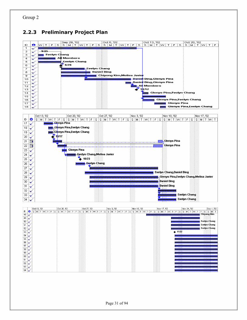
2.2.3 Preliminary Project Plan

Group 2
Page 32 of 94
2.2.4 Baseline Plan

Group 2
Page 33 of 94
2.3 Feasibility Study: Cost Benefit Analysis
2.3.1 Economic Feasibility
TANGIBLE BENEFITS WORKSHEET
HMI
Year 1 through 5
A. Cost Reduction or Avoidance $ 12,000
B. Increased Flexibility 7,000
C. Increased Speed of Activity 12,000
D. Improvement in management planning or control 18,000
TOTAL Tangible benefits $ 49,000
ONE-TIME COSTS WORKSHEET
HMI
Year 0
A. Development Costs $ 17,000
B. New Hardware 12,000
C. New Software 3,000
E. User Training 2,500
TOTAL One-Time Costs $ 34,500
RECURRING COSTS WORKSHEET
HMI
Year 1 through 5
A. System Software Maintenance $ 17,000
B. Incremental data storage required 1.500
C. Incremental Communications 2,000
D. Supplies 1,000
TOTAL Recurring Costs $ 21,500

Group 2
Page 34 of 94
2.3.2 Feasibility Analysis
Year of Project
0 1 2 3 4 5 TOTALS Net Economic Benefit $0 $49,000 $49,000 $49,000 $49,000 $49,000 Discount Rate (11%) 1.0000 0.9009 0.8116 0.7312 0.6587 0.5935 PV of Benefits $0 $44,144 $39,769 $35,828 $32,278 $29,079 NPV of all BENEFITS $0 $44,144 $83,914 $119,742 $152,020 $181,099 $181,099 One-time COSTS ($34,500) Recurring Costs $0 ($21,500) ($21,500) ($21,500) ($21,500) ($21,500) Discount Rate (11%) 1.0000 0.9009 0.8116 0.7312 0.6587 0.5935 PV of Recurring Costs $0 ($19,369) ($17,450) ($15,721) ($14,163) ($12,759) NPV of all COSTS ($34,500) ($53,869) ($71,319) ($87,040) ($101,203) ($113,962) ($113,962) Overall NPV $67,137 Overall ROI (overall NPV / NVP all COSTS) 0.5891 Break-even Analysis Yearly NPV Cash Flow ($34,500) $24,775 $22,320 $20,108 $18,115 $16,320 Overall NPV Cash Flow ($34,500) ($9,725) $12,594 $32,702 $50,817 $67,137
Project break-even occurs between years 1 and 2
Break-even fraction - ((22,320 - 12,594) / 22,320) = .4358
Actual break-even occurred at 1.44 years

Group 2
Page 35 of 94
2.3.3 Break-Even Point Analysis
-40000
-20000
0
20000
40000
60000
80000
Year0 Year1 Year2 Year3 Year4 Year5
Yearly NPV CashFlowOverall NPV Cash Flow

Group 2
Page 36 of 94
2.4 Risk Management
Project Size
The project has a budget of nearly $ 70,000.00. The number of members on the project
team is 5. The HMI for NIRO Fluid Bed Processor involves a number of parties. The basic data
for the system is readily available so the creation of the system will not be a large undertaking.
Project Structure
The project involves upgrading the HMI for NIRO Fluid Bed Processor with ISQL
database software, which is available for analysts to examine and study. Therefore, the
requirements for the project are highly structured and easily obtainable.
Time Constraints
1. The duration of this project lasts weeks, months, or even years. During such a long
period, many changes may occurs, most of which are difficult to predict. Such changes
may have a significant impact on project costs, technology, and resources. The longer
the duration of the project, the more uncertain are the execution times and costs.
2. This project is complex in nature, involving many interrelated activities and participants
from both within the organization and outside it (e.g., suppliers, subcontractor). (Our
example is highly simplified for the purpose of easier demonstration.)
3. Delays in completion time may be very costly. Penalties for delays may amount to
thousands of dollars per day. Completing projects late may result in lost opportunities
and ill will as well.
4. Project activities are sequential. Some activities cannot start until others are completed.
Systems Interdependence
The system is composed of more than 100 parts. It is mutually dependent only to its
components that made it to a system and not to any other system. In order for the NIRO Fluid
Bed Dryer to fully be functional, the components have to be commissioned upon then the

Group 2
Page 37 of 94
installations of the parts. Without these components that the system is interdependent with,
the entire system is not functional.
Quality
The quality to produce drug depends on the operations of the system. The system has
to be maintained orderly and meet all its calibration dues. For security health reasons, the
equipments have to be tested and qualified before making any processes.
Clarity
Before the processes are being executed, any confusion to the system is already been
eliminated during the validation phase of the project. The validation phase helps in eliminating
unnecessary or confusing features of the system to avoid risk to the process. Otherwise, if the
confusion is this present upon execution of a process, the operator has to re-train to fully
understand how the system works.
Efficiency
For security issues, every drug company must produce efficient quality of drug products.
Without efficiency of the system due to over due of the calibration or out of tolerance of the
equipment, the batch products are not secured to be in compliant to the FDA’s regulation.
Thus, may caused fatal results upon taken by the patients. All parts of the equipment have to
be calibrated, maintained and properly cleaned.
Traceability
It is important to have back up copies of all the history of equipment. Tracing files
manually is a tough job. The system is designed to store information that could easily be
traced.
There are some instance that when making drug batches, there are pass and reject
tablets. In case where the FDA request for a copy of the file months ago, it is easy to supply
the needs if the system can trace the procedures.
In order to track the previous document of a specific procedure, the administrator can
go back to day and time the product was made.

Group 2
Page 38 of 94
Familiarity with Technology or Application Area
The development group is familiar with the technology that will likely be used to
construct the system. However, the user group is not familiar with the application area since
they don’t understand the technical diagrams and the components in the system. Furthermore,
they are intimidated to use the system due to this lack of understanding.
Project Size
The project is huge. Since the basic data for the system is readily available, the creation of the system will not be large undertaking. Section 1.01 Risk: High
Project Structure
The requirements for the project are highly structured and obtainable. The existing HMI for NIRO Fluid Bed Processor is available for analysts to examine and study. Section 1.02 Risk: Medium High
Time Constraint
The duration of this project lasts 12 months period. During such a long period, many changes may occurs, most of which are difficult to predict. Such changes may have a significant impact on project costs, technology, and resources. The longer the duration of the project, the more uncertain are the execution times and costs. Section 1.04 Risk: High
System Interdependence
The good feature about this system is that it is not interdependent among other system but dependent to its components, such as process airflow, atomizing air, etc. Without these components that the system is interdependent with, the entire system is not functional. Section 1.05 Risk: Low
Quality
For health reasons, the quality of the product is extremely important. Section 1.08 Risk: Extremely High
Clarity
Before the processes are being executed, any confusion to the system is already been eliminated during the validation phase of the project. The validation phase helps in eliminating unnecessary or confusing features of the system to avoid risk to the process. Section 1.06 Risk: Low
Efficiency For security issues, every drug company must produce efficient

Group 2
Page 39 of 94
quality of drug products. Without efficiency of the system due to over due of the calibration or out of tolerance of the equipment, the batch products are not secured to be in compliant to the FDA’s regulation. Thus, may caused fatal results upon taken by the patients. All parts of the equipment have to be calibrated, maintained and properly cleaned. Section1.07 Risk: Extremely High
Traceability
It is important to have back up copies of all records. When making drug batches, there are pass and reject tablets. In case where the FDA request for a copy of the file months ago, it is easy to supply the needs if the system can trace the procedure. In order to track the previous document of a specific procedure, the administrator can go back to day and time the product was made. Section 1.09 Risk: Medium High
Familiarity with Technology or Application Area
The development group is familiar with the technology that will likely be used to construct the system, since they will simply upgrade current system capabilities. The user group is not familiar with the application area. The users who operate the systems slightly understand the technical diagrams and the components in the system. Section 1.03 Risk: Medium Low

Group 2
Page 40 of 94
3. Project Analysis
3.1 Stakeholder Identification
Machine Operators
Machine Operators are very important stakeholders to the system because they interact
with the system in a constant daily-basis. They interact with the system automatically by
using the different screens. They are responsible for monitoring and controlling the production
of materials. Machine operators have access to the operator’s screen, air preparation screen,
alarm screen, and trend screens.
Management Personnel (Department Supervisors and Department Managers)
Department Supervisors and Managers have access to the system according to their
department. They are responsible for monitoring and controlling the production of materials.
They have access to the operator’s screen, air preparation screen, alarm screen, and trend
screens. They are also authorized to abort and to halt batches.
Stakeholders
Maintenance Personnel
Management Personnel
Machine Operators
Electrical Engineers
Department Supervisors
Department Managers

Group 2
Page 41 of 94
Maintenance Personnel
Maintenance Personnel has the same level of interaction as the trained operator. In
addition to the automatic interaction they can manually control the system. They can start and
stop all machine motors, and open and close all valves to perform system maintenance on a
daily basis.
Electrical Engineers
Electrical Engineers have full access to the system. They have administrative access to
the system, such as the ability to create new user accounts, reset user passwords. Electrical
Engineers also troubleshoot hardware and application problems, as well as, networking
problems. They also maintain the communication between the two servers (ISQL server and
terminal server).

Group 2
Page 42 of 94
3.2 Gathering Requirements
3.2.1 Interviewing (Informal)
See Attached.

Group 2
Page 43 of 94
3.2.2 USE-CASE Scenarios
A Use Case Scenario is distinctive interaction that a user has with the system in order to
achieve a particular purpose. It provides the basis of communication between the sponsors and
the developers in planning the project. The Use Case Scenario captures some user-visible
functions. A diagram is created soon after to have better picture.
Actor: Machine Operator
HMI System: The trained operator is in front of the HMI system, which displays
different options the user can select from.
Main System Interface: After selecting the login option from the HMI System, the
HMI main system interface displays the login screen.
Login Screen: The Machine Operator uses the virtual keyboard to input his/her User-
ID and password. The User-ID and password are compared to the one stored on the database.
If the wrong user name and/or password are entered, an error message will be display, and
he/she will be asked to re-enter the information. If User-ID and password are verified, the
machine operator is logged on to the system and with his/her proper level of authorization and
security.
Logon to System: Once the machine operator is logged on to the system, he/she will
be able to select from a list of displayed options: inflation/deflation of the container and filter
gaskets, raising and lowering of the dryer filter, and spray test.
Perform Task 1: The machine operator press the INFLATE/DEFLATE FILTER
GASKET button on the screen to inflate or deflate the filter sealing gasket and the upper
container gasket and the inlet plenum gasket.
Perform Task 2: The machine operator presses the RAISE or LOWER button on the
screen to raise or lower the exhaust air filter. The operator clicks and holds the button to
actuate the cylinder. This method is useful to install the exhaust filter and the filter gasket.
Group 2
Page 44 of 94
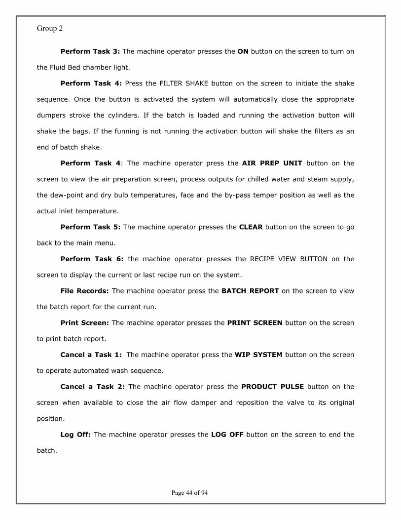
Perform Task 3: The machine operator presses the ON button on the screen to turn on
the Fluid Bed chamber light.
Perform Task 4: Press the FILTER SHAKE button on the screen to initiate the shake
sequence. Once the button is activated the system will automatically close the appropriate
dumpers stroke the cylinders. If the batch is loaded and running the activation button will
shake the bags. If the funning is not running the activation button will shake the filters as an
end of batch shake.
Perform Task 4: The machine operator press the AIR PREP UNIT button on the
screen to view the air preparation screen, process outputs for chilled water and steam supply,
the dew-point and dry bulb temperatures, face and the by-pass temper position as well as the
actual inlet temperature.
Perform Task 5: The machine operator presses the CLEAR button on the screen to go
back to the main menu.
Perform Task 6: the machine operator presses the RECIPE VIEW BUTTON on the
screen to display the current or last recipe run on the system.
File Records: The machine operator press the BATCH REPORT on the screen to view
the batch report for the current run.
Print Screen: The machine operator presses the PRINT SCREEN button on the screen
to print batch report.
Cancel a Task 1: The machine operator press the WIP SYSTEM button on the screen
to operate automated wash sequence.
Cancel a Task 2: The machine operator press the PRODUCT PULSE button on the
screen when available to close the air flow damper and reposition the valve to its original
position.
Log Off: The machine operator presses the LOG OFF button on the screen to end the
batch.

Group 2
Page 45 of 94
Actor: Maintenance Personnel
HMI System: The system administrator is in front of the HMI system, which displays
different options the user can select from.
Main System Interface: After selecting the login option from the HMI System, the
HMI main system interface displays the login screen.
Login Screen: The System Administrator uses the virtual keyboard to input his/her
User-ID and password. The User-ID and password are compared to the one stored on the
database. If the wrong user name and/or password are entered, an error message will be
display, and he/she will be asked to re-enter the information. If User-ID and password are
verified, the machine operator is logged on to the system and with his/her proper level of
authorization and security.
Logon to System: Once the system administrator is logged on to the system, he/she
will be able to select from a list of displayed options: process airflow, air prep airflow,
atomizing air, solution flow, or inlet temp on the operator’s screen.
Task 1: The system administrator presses the PROCESS AIRFLOW button on the
screen to display the controller window, then press the ENTER button when finish.
Task 2: The system administrator presses the AIRPREP AIRFLOW button on the
screen to view or change the process set point, then press the ENTER button when finish.
Task 3: The system administrator presses the ATOMIZING AIR button on the screen
to view or change the controller outputs, then press the ENTER button when finish.
Task 4: The system administrator presses the SOLUTION FLOW button on the screen
to view or change the process variables, then press the ENTER button when finish.
Task 5: The system administrator presses the SHAKEUP SETUP button to view the
several shake parameters.
Task 5: The system administrator presses the SHAKEUP TIME AND SHAKE DOWN
TIME button to control the up and down time of the shake cylinder during the shake cycle.

Group 2
Page 46 of 94
Log Off: The maintenance personnel press the LOG OFF button on the screen to end
the batch.
Actor: Management Personnel (Department Supervisors and Department Managers)
HMI System: The Management Personnel is in front of the HMI system, which displays
different options the user can select from.
Main System Interface: After selecting the login option from the HMI System, the
HMI main system interface displays the login screen.
Login Screen: The Management Personnel uses the virtual keyboard to input his/her
User-ID and password. The User-ID and password are compared to the one stored on the
database. If the wrong user name and/or password are entered, an error message will be
display, and he/she will be asked to re-enter the information. If User-ID and password are
verified, the machine operator is logged on to the system and with his/her proper level of
authorization and security.
Logon to System: Once the management personnel are logged on to the system,
he/she will be able to select from a list of displayed options: process airflow, air prep airflow,
atomizing air, solution flow, or inlet temp on the operator’s screen.
Task 1: The management personnel presses the CONFIGURE button on the screen to
display the I/O simulation switch, which allows for operator training with all processor I/O
disabled.
Task 2: The management personnel press the ABORT button on the screen to end the
batch.
Task 3: The management personnel press the RECIPE EDIT button on the screen to
edit a recipe.
Task 4: The management personnel press the EDIT FUNCTION button on the screen
to edit a value or create a recipe.

Group 2
Page 47 of 94
Log Off: The management personnel press the LOG OFF button on the screen to end
the batch.
Actor: Electrical Engineer
HMI System: The Electrical Engineer is in front of the HMI system, which displays
different options the user can select from.
Main System Interface: After selecting the login option from the HMI System, the
HMI main system interface displays the login screen.
Login Screen: The Electrical Engineer uses the virtual keyboard to input his/her User-
ID and password. The User-ID and password are compared to the one stored on the database.
If the wrong user name and/or password are entered, an error message will be display, and
he/she will be asked to re-enter the information. If User-ID and password are verified, the
machine operator is logged on to the system and with his/her proper level of authorization and
security.
Logon to System: Once the Electrical Engineer is logged on to the system, he/she will
be able to select from a list of displayed options: process airflow, air prep airflow, atomizing
air, solution flow, or inlet temp on the operator’s screen.
Task 1: The electrical engineer presses the PID tuning button on the screen to access
the control loop tuning, such as setting the control loop’s GAIN, RESET and TIME. The control
tolerance and deviation alarm time settings are also set/on these screens.
Task 2: The electrical engineer presses the CHANGE PASSWORD button on the screen
to change current users’ password for the system.
Task 3: The electrical engineer presses the WINDOWS button on the screen to retrieve
the batch files, report and the alarm files.
Log Off: The electrical engineer presses the LOG OFF button on the screen to end the
batch.

Group 2
Page 48 of 94
Actor: IT Personnel
HMI System: The IT Personnel is in front of the HMI system, which displays different
options the user can select from.
Main System Interface: After selecting the login option from the HMI System, the
HMI main system interface displays the login screen.
Login Screen: The IT Personnel uses the virtual keyboard to input his/her User-ID and
password. The User-ID and password are compared to the one stored on the database. If the
wrong user name and/or password are entered, an error message will be display, and he/she
will be asked to re-enter the information. If User-ID and password are verified, the machine
operator is logged on to the system and with his/her proper level of authorization and security.
Logon to System: Once the IT Personnel are logged on to the system, he/she will be
able to configure the network connection of the system.
Log Off: The IT Personnel presses the LOG OFF button on the screen to end the batch.
Actor: Validation Specialist
HMI System: The Validation Specialist is in front of the HMI system, which displays
different options the user can select from.
Main System Interface: After selecting the login option from the HMI System, the
HMI main system interface displays the login screen.
Login Screen: The Validation Specialist uses the virtual keyboard to input his/her
User-ID and password. The User-ID and password are compared to the one stored on the
database. If the wrong user name and/or password are entered, an error message will be
display, and he/she will be asked to re-enter the information. If User-ID and password are
verified, the machine operator is logged on to the system and with his/her proper level of
authorization and security.

Group 2
Page 49 of 94
Logon to System: Once the Validation Specialist is logged on to the system, he/she
will be able to commission the system requirements and specifications.
Log Off: The Validation Specialist presses the LOG OFF button on the screen to end the
batch.
Actor: ISQA Compliance Specialist/QA Specialist
HMI System: The ISQA Compliance Specialist/QA Specialist is in front of the HMI
system, which displays different options the user can select from.
Main System Interface: After selecting the login option from the HMI System, the
HMI main system interface displays the login screen.
Login Screen: The ISQA Compliance Specialist/QA Specialist uses the virtual keyboard
to input his/her User-ID and password. The User-ID and password are compared to the one
stored on the database. If the wrong user name and/or password are entered, an error
message will be display, and he/she will be asked to re-enter the information. If User-ID and
password are verified, the machine operator is logged on to the system and with his/her proper
level of authorization and security.
Logon to System: Once the ISQA Compliance Specialist/QA Specialist is logged on to
the system, he/she will be able to document the procedures and specifications of the system.
Log Off: The ISQA Compliance Specialist/QA Specialist presses the LOG OFF button on
the screen to end the batch.

Group 2
Page 50 of 94
3.2.3 Brainstorming
Ability to Acquire Production Data in
Full Resolution
User Friendly
Security and Authentication
Ability to Acquire Production Data in
Real Time
Application Role
Touch Screen HMI
Available 24/7 Redundancy
Ability to Raise Alarms
Can be customized for Any Assembly
Line
Reduce Expenses and Resources in Assembly
Line Control and Monitoring
Privacy of Proprietary Information
HMI Layout Design
Email Notification
Computerized Production
Line Control

Group 2
Page 51 of 94
Categorization
Speed
• HMI Layout Design • Ability to Acquire Production Data in Real Time
Convenience
• Computerized Production Line Control • User Friendly
• Email notification
• Available 24/7, Redundancy
• Touch Screen HMI
Security
• Security and Authentication
• Application Role
• Privacy of Proprietary Information
Efficiency
• Ability to Acquire Production Data in Full Resolution
• Ability to Raise Alarms
Benefits
• Reduce Expenses and Resources in Assembly Line
Control and Monitoring
Future Enhancement
• Can be Customized for Any Assembly Line
Name
Name
Name
Name
Name
Name

Group 2
Page 52 of 94
Prioritization
Convenience Security Efficiency Speed Benefits Future
Enhancement
Evelyn 15 30 30 15 5 5 100 Daniel 30 30 30 10 0 0 100 Glenys 20 20 20 20 10 10 100 John 20 20 20 20 15 5 100 Melissa 20 10 20 50 0 0 100
Total 105 110 120 115 30 20 Ranking of Priorities:
1. Efficiency
2. Speed
3. Security
4. Convenience
5. Benefits
6. Future Enhancements

Group 2
Page 53 of 94
3.3 Documenting Requirements
3.3.1 Functional Requirements
The functional requirements of the Human-Machine Interface, commonly known as the
Graphical User Interface (GUI), are concerned with the various devices representing each
physical Air Handler, Dust Collector, Temperature Transmitter, and Pressure Gauge, etc., which
makes up a system. The interface utilizes multiple colors and animation for depicting specific
components of each piece of equipment. Also, the interface is developed in a series of arranged
row placed one above another type of structured menu for easy accessing to all system
components. This makes the system a user-friendly interface.
The interface is tagged to connect to the project network. The interface is designed to
collect data from the network to the controller via the Industrial SQL Server. It is also designed
from the interface application to the primary network controller to allow inputs. On the other
side of the token, the additional feature of the interface is that it allows a system user to alter
set points within the pre-configured limits and the ability to view dynamic data only.
Depending to the level of security, the operator performs specific operations based on
role definition. The functional requirements of the security of the system should have the
logical and authority checks to ensure that only authorized individual can access to the system.
The authorized individual accessing the system can update, or modify set points. The system
has the ability to create unique user identification and passwords. This password is encrypted
when entered and stored on the system. This password expires and also protects screen
lockout.
The functional requirements of the database of the system are the ability to collect
massive data in lesser time and to generate reports. The system collects data at a rate less
than 10 minutes intervals; the system collects another data and stores at an interval of less
than an hour. A new feature that will be implemented is the built in pulse beat that notifies via

Group 2
Page 54 of 94
Alarm if there is a loss of communication between the Industrial SQL Server and the PLCs in
the field.
The reporting tool is another recurring problem of the system. A new feature is created
to have the ability to generate on screen or hard copy of batch reports. The system provides
the ability to produce a Data Report that includes time and corresponding temperature (in min,
max, avg.), humidity (in min, max, avg.) and the direction of the airflow. It also provides the
ability to show the conditions of a room by selecting a room and a day and to show the number
of alerts and alarms generated for a day by selecting the day. Also, the ability of the system is
to be able to query for minimum of 6 months per room.
The Audit Trailing is considered functional requirements for electronic records and
signatures. Its availability to retain records of history and could detect invalid or altered
records is an important aspect for the company. The system have secure computer generated
audit trails for all data that records user identification, the date and time of operator entries
and the nature of the action, e.g. creation and modification of E-records. The availability of the
electronic or hard copy of the report is important for review and reporting purposes. This
requirement is complying with the stringy rule of the FDA in the 21 CFR Part 11.
The most important of the functional requirements is saving and backing-up the data.
Losing data is the worst scenario of any company. It is a lost. The system is capable of having
the regular back up stored in a separate storage device over the network for safety
precautions. Besides from backing up the system, the system has the ability to restore
electronic records and data and generates accurate and complete copies of records in electronic
and paper forms. The backed up files are retrievable upon request.

Group 2
Page 55 of 94
3.3.2 Non-Functional Requirements
The Non-functional requirements of the system are the Hardware components, the
Operating system and the Network connections. These Non-functional requirements are used
to meet the certain requirements to install the Interface, called InTouch® and the database,
called Industrial SQL. The server used for back up and storage of multi-million dollars worth of
files has certain requirements to meet. The requirements should at least support and serve 10
concurrent users.
The requirements for the server: 1 PC with P350 processor and 256 MB of RAM;
Microsoft NT 4.0 Server (Intel) with Service Pack 5; Microsoft Transaction Server 2.0 or higher,
MTS is a component of the Windows NT 4.0 Option Pack; Microsoft Internet Explorer 4.01 or
later; SQL Server and utilizes 7.0. An additional requirement for the server for Clients for each
of the 10 PCs: Microsoft Windows NT and Microsoft SQL Server 7.0 Client connectivity utility.
The hardware components should at least meet the minimum requirements or better.
The performance of the system depends on the availability of the parts. The minimum
hardware required to run the system at average performance is: 100 MHz Pentium processor,
32 MB of RAM plus 8 MB per 5K tags, and 100 MB free hard disk space. Otherwise, a
suggested system required is 200 MHz Pentium or greater, 8 MB of RAM per 5K tags, and 500
MB free hard disk space.
The Operating system should at least meet the minimum requirements or better. The
Operating System required to function the system properly is: MS Win 95 SP1/ 98 SE/ NT 4.0
SP5 or greater. A recommended Internet Explorer 5.0 for better quality. Windows NT 4.0 is
required for the installation of the Industrial SQL Server application. Otherwise, the other non-
functional requirements are for the interface application.
For any standard Network connections, the system should support any standard
NetBIOS network: Ethernet 10/100, Novell, Token Ring, Arcnet, etc. DECnet, Serial and
TCP/IP.

Group 2
Page 56 of 94
3.4 Modeling Requirements
3.4.1 USE-CASE Diagram
O p e ra to r In te r lo c kS c re e n s
W a s h In P la c eIn te r lo c k s
T re n d M e n u a n dT re n d S c re e n s
S e le c t R e c ip eS c re e n
S o lu t io n P u m pC le a n W in d o w
P u m p T e s tW in d o w
S e c u r ity S c re e n A la rm s
R e c ip e V ie w
W a s h In P la c e
R e c ip e E d it S c re e nV ie w O N L Y
B a tc h R e p o r t V ie wS c re e n
S o lu t io n P u m pP u rg e W in d o w
P u m p M o d e S e le c tW in d o w
F lu id B e d T re n d s
A ll O p e ra to r L e v e lS c re e n s
L o o p In p u tW in d o w
L o o p T u n in gS c re e n s V ie w s
O N L Y
F ilte r S h a k eP a ra m e te rs U p /
D o w n T im e
A ll M a in te n a n c eL e v e l S c re e n s C o n f ig u re W in d o w
P L C I /O S im u la t io n
R e c ip e N a m e sE d it W in d o w
R e c ip e E d it
D ry e r B a tc h A b o r t
F il te r S h a k eP a ra m e te rs
S c re e n
R e c ip e A la rm sV ie w a n d E d it
A l l S u p e rv is o rS c re e n s
L o o p T u n in gS c re e n s
C o n f ig u reP a s s w o rd
D ry e r B a tc h A b o r t
C o n f ig u re U s e r
E x it to W in d o w s
N e tw o rk in g
C o m m is s io n in g
D o c u m e n ta t io n
O p e ra to r S c re e n(L E V E L )
M a in te n a n c eP e rs o n n e l S c re e n
S u p e rv is o r a n d /o rM a n a g e r S c re e n
E le c t r ic a l E n g in e e rS c re e n
M a c h in eO p e ra to r
IT P e rs o n n e l
V a lid a t io n S p e c ia lis t
IS Q A /Q A S p e c ia lis t
M a in te n a n c eO p e ra to r
E le c t r ic a l E n g in e e r
M a in te n a n c e P e rs o n n e l
< < E X T E N D E D > >
< < E X T E N D E D > >
<<E
XTE
ND
ED
>>
<<E
XTEN
DED
>>
<<EX
TEN
DE
D>>
<<E
XTE
ND
ED>>
M a in ta in in gD a ta b a s e
D a ta b a s e D e s ig n e r
<<E
XTE
ND
ED>>
< < IN C L U D E > >
< < IN C L U D E > >
< < IN C L U D E > >
< < IN C L U D E > >
< < IN C L U D E > >
< < IN C L U D E > >
< < IN C L U D E > >
< < IN C L U D E > >
< < IN C L U D E > >
< < IN C L U D E > >
< < IN C L U D E > >
< < IN C L U D E > >
< < IN C L U D E > >
< < IN C L U D E > >
< < IN C L U D E > >
< < IN C L U D E > >< < IN C L U D E > >

Group 2
Page 57 of 94
3.4.2 DFD Diagrams
3.4.2.1 Grammatical Analysis
The goal of designing and developing a Human-Machine Interface is to create a
convenient way for trained operators to monitor and control equipments of the facility from
their personal computers. It provides the ability to produce reports for analysis of productions
and also has functions of backing-up the critical data, and restoring for any unexpected
accidents. Our new HMI has an easy configuration and profoundly improved alarm handling
performance, will greatly improve the quality of your information while reducing the
configuration time.
Monitoring and controlling is an important task, so the operators must login with their
valid passwords to use the system. The authentication process allows the system to determine
who is using the system. This is important for the company to keep track of the operators’
history so that it could detect invalid or altered records. Old versions of HMI had similar
abilities but they just had only one login name and password, so it was not possible to find out
who logged in and when. But our new system allows multiple users and has a log-writer to
generate the electronic records and signatures. System administrators are allowed to create
new users with their level of security and passwords through User Management Panel, which
helps to maintain the users of the system. Depending on the level of security, operators
perform specific operations based on role definition. When a user logs in, one session is made.
The password is encrypted when entered and stored on the system. The session expires after
certain period of time and also protects screen lockout. The authorized individual can update,
or modify set points. The log-writer has ability to make multiple log files, which means it
maintains the log files with multiple small files instead of a big one for faster report production
and easier storage maintenance.
The operators will be trained to use the system, but untrained users may be able to
operate the system as well. So, the user interface of the system will not be complicated as old

Group 2
Page 58 of 94
versions. The interface mostly consists of physical Air Handler, Dust Collector, Temperature
Transmitter, and Pressure Gauge. The interface is designed to collect data from the network to
the controller via the Industrial SQL Server. It is also designed from the interface application to
the primary network controller to allow inputs. The additional feature of the interface is that it
allows a system user to alter set points within the pre-configured limits and the ability to view
dynamic data only. The Industrial SQL Database Server collects massive data - corresponding
temperature, humidity and the direction of the airflow - to generate reports.
The system backs up data regularly and stores a separate storage device over the
network. Besides from backing up the system, the system has the ability to restore electronic
records and data and generates hard copies of records.
BLUE: VERB RED: NOUN

Group 2
Page 59 of 94
3.4.2.2 Context Diagram AS-IS Context Diagram
0 .0H M I
O p e r a to r
M a n a g e r
M a c h in eO p e r a to r C o m m a n d s
R e s u l t s
M a n a g e m e n t R e p o r t s
C o n t r o l
TO-BE Context Diagram
0 .0H M I
O p e ra to r
M a n a g e r
M a ch in e
O p e ra to rC o m m a n d s R e s u lts
M a n a g e m e n t R e p o rts
C o n tro l
IS Q L
S a ve d D a ta
C o n tro l D a ta
C o n tro l O p e ra tio nE le c tric a lE n g in e e r

Group 2
Page 60 of 94
3.4.2.3 General DFD TO-BE System
Operator
ElectricalEngineer
Manager
MonitoringSensor Device
New User Data
Operator Command
Real-timemachine data(user format)
Request for Data
ISQL
Saved Results
1.0Translate and
Transfer OperatorCommand
MachineController
3.0Retrieve Real-
time Data Real-timeMachine Data
O.C. for R
4.0Control
Machine
O.C.for C
ControlCommand
8.0Update
Database
Request forUpdating2
Request for Updating
5.0ProduceReports
Data for Reports
Management Reports
User Log File
2.0Update User
Log File
CurrentUser Data
Formatted User Log Data
User Data File
User data
7.0Create User
Formatted New User Data
6.0Backup and
RestoreRequest for
Backup and RestoreBackup Command
DB BackupFile
Formatted DB Data
DB Raw DataData for Restore
Request for Updating M.P.
Request forUpdating C.P.

Group 2
Page 61 of 94
3.4.2.4 Decompositions TO-BE Decomposition 1.0 Translate and Transfer Operator Command
1.1Translate Operator
Commands
1.2Authentication
Process
1.3Transfer Operator
Commands
Operator CommandsLogin Data
Login Data
User Data
UpdatedUserData
OperatorCommands
Machine ControlCommands
Request for Data Commands
User Data File

Group 2
Page 62 of 94
TO-BE Decomposition 1.2 Authentication Process
1.2.1Receive Login
Data
Login Data
1.2.2Verify User
1.2.3Approve Login
User Data
Updated UserData
FormattedLogin Data
Current UserInformation
User Data File

Group 2
Page 63 of 94
TO-BE Decomposition 2.0 Update User Log File
2.1Recieve Request
for Updating
2.2Check User Log
File
2.3Create New Log File
User LogFiles
2.4Update User Log
Operation Data
User Data
Updated Data
Request for new log file
New Log File
UpdatedData
FormattedData

Group 2
Page 64 of 94
TO-BE Decomposition 3.0 Retrieve Real-time Data
3.1TranslateOperator
Commands
3.2Request for Update
3.3Receive Machine
Data
Request for Data Commands
User Data(Monitor)
Update Database
Update User Log
Request forMachine Data
Machine Data
FormattedReal-time Data
3.4Display
Real-time Data
Real-time Information
MonitoringSensorDevices

Group 2
Page 65 of 94
TO-BE Decomposition 4.0 Control Machine
4.1TranslateOperator
Commands
4.2Request for Update
4.3Transfer
Control Commands
Request forMachine Control
Commands
User Data(control)
Update Database
Update User Log
Operator Commands
Control Commands
MachineControllers

Group 2
Page 66 of 94
TO-BE Decomposition 5.0 Produce Reports
5.1Retrieve Dataand Transfer
5.2Produce User
Reports
5.3Produce Machine
Reports
5.4Generate
Management Reports
Request for Reports
UserData
MachineData
Machine Data
User Data
User Reports
Machine ReportsManagement
Reports
User DataFiles
ISQL
User LogFiles
User Log Data

Group 2
Page 67 of 94
TO-BE Decomposition 6.0 Backup and Restore
6.1TransferRequest
6.2Backup
Database
6.3Restore
Database
DB BackupFile
Text Backup Data
ISQL
DB Data
Backup Data
Request for Backup
Request forRecovery
Old DB Data
System Commands

Group 2
Page 68 of 94
TO-BE Decomposition 7.0 Create User
7.1Receive New
UserInformation
7.2Verify New
User
7.3Update User
Data File
User Data
Request forVerification
New User Information
FormattedNew User
Information
User ListUser Data
Files

Group 2
Page 69 of 94
3.4.3 Data Dictionary
Data Identifier
Description
Login Data UserName + Password
UserName {[A | B | C |…| a | b | c |…]}
Password {[A | B | C |…| a | b | c |…| 0 | 1 | 2 |…| ~ | ! | @ | # |…]}
New User Data UserName + Password + Employee ID + Name + Address + Phone Number + Email Address + Security Level
Name FirstName + LastName + (Middle Init.)
Address Street + ([“Suite #” | ”Apt #” | “Room #”]) + City + State + Zipcode
Phone Number (1) + Area Code + Number
Email Address UserName + @ + Valid Domain Name
Valid Domain Name
Host + . + Type of Domain
Type Of Domain [“com” | “org” | “edu”]
Security Level [“Machine Operator” | ”Maintenance” | ”Electrical Engineer” | “Manager” | ”Supervisor” ]
FirstName {[A | B | C |…| a | b | c |…]}
LastName {[A | B | C |…| a | b | c |…]}
Operator Command
Command + (Initial Value)

Group 2
Page 70 of 94
Data Identifier
Description
Command [“INFLATE” | “DEFLATE” | “RAISE” | “LOWER” |“ON” | “OFF” | “FILTER SHAKE” | “CLEAR” | “RECIPE VIEW” | “PRINT” | “WIP” | “LOG ON” | “LOG OFF” | “PROCESS” | “ENTER” | “CHANGE PASSWORD”]
User Log Data Time + UserName + Operation
Time Year + Month + Day + Hour + Minute + Second
Operation Operator Command + (Error)
Error Error Number + Error Message

Group 2
Page 71 of 94
4. System Specifications
4.1 Requirement Specification
The Requirement Specifications are usually developed directly by the request of the
customers. The Requirement Specification specifies the fundamental requirements of the
system in terms of WHAT the system must do. This requirement is divided into subsections:
4.1.1 Structured English
Process 1.0 Translate and Transfer Operator Command
- Receive Operator Command
- Verify Operator Commands
- If Operator Command is Login Then
Send to 1.2 Authentication Process
Else
Send to 1.3 Control Process
Process 1.2 Authentication Process
- Receive Login Data
- Verify UserName and Password from User Data File
- If UserName and Password match Then
Approve Login
Else
Deny Login
- Update User Log File
Process 2.0 Update User Log File
- Receive Updated Data
- Check if Log File available
- If Log File is not available
Create a new User Log File
- Write Updated Data to Log File

Group 2
Page 72 of 94
Process 3.0 Retrieve Real-time Data
- Receive Operator Command
- Update User Log File
- Receive Machine Data
- Display Machine Data
Process 4.0 Control Machine
- Receive Operator Command
- Update User Log File
- Send Command to Machine Controller
Process 5.0 Produce Reports
- Retrieve User Data
- Retrieve User Log Data
- Retrieve Machine Data from ISQL
- Generate Management Report
Process 6.0 Backup and Restore
- Receive System Command
- IF System Command is for Backup
Back up Database
Else IF System Command is for Restore
Restore Database from Backup File
Process 7.0 Create User
- Receive New User Data
- Verify New User
- If already exist Then
Show Error Message
Else
Update User Data File

Group 2
Page 73 of 94
4.1.2 Decision Trees
Is this aValid User?
DoUserName
andPasswordmatch?
What kind ofUser?
YES
Make a validsession
Denied Access
YES
NO
NO
Is thisControl
Command?
Is this avalid user
info?Ope
rato
r
Create
User
Manager
Create New User
Reenter validuser info.
YES
NO
Control Machine
Display MachineData
YES
NO
PrintManagement
Report
Is thisBackup?
What type ofCommand?
Engine
er Backup and
Restore Backup Data
Restore Data
YES
NO

Group 2
Page 74 of 94
4.1.3 Decision Tables
Decision Table: Login Process
Decision Table: Operation Process
Rules Conditions
1 2 3 4 Is this a valid session?
Y Y N N
Do username and password match?
Y N Y N
Actions Process Session
X X - -
Make Session
- - X -
Deny Access - X
Rules Conditions
1 2 3 4 5 6
What kind of user?
Operator Operator Manager Manager Engineer Engineer
Is this a control command?
Y N Y N Y N
Actions
Control Machine
X
Display Machine Data
X
Print Report X X
Process Engineer Commands
X X

Group 2
Page 75 of 94
Decision Table: Engineer Process
Rule Conditions
1 2 3 4 5 6 7 8 What type of command?
CU CU CU CU BR BR BR BR
Is this user info valid?
Y Y N N Y Y N N
Is this backup? Y N Y N Y N Y N
Actions
Create New User
X X
Reenter valid user info.
X X
Backup data X X
Restore data X X
CU: Create User BR: Backup and Restore

Group 2
Page 76 of 94
4.2 Functional Specification
Functional specification denotes the behavior of the system and how its components are
integrated. These specifications therefore describe HOW the system has been designed to
obtain the WHAT specified in the Requirement Specification.
Interface Requirement - The system has an interface (HMI), which would operate and
perform a process. The interface should be user-friendly and allow users to navigate various
graphical screens without interference to the process being executed. It has constant network
connectivity. It allows the Industrial SQL Server to collect data from the primary network
controller.
Database Requirement – The system database is the central storage of critical data;
the system has the support for the Universal Time Code to eliminate issues with time zones
and daylight savings; the system is capable to remote buffering data at the I/O device server,
so that the data can still be stored at a later time if connection to I/O is lost.
Back up and Support Requirement – The system is capable of having the software
and data it contains regularly backed-up to a separate storage device over the network.
Alarm Management Requirement – The alarm in the system will initiate when a
communication connection loss to any controllers. The system will automatically display new
alarms regardless of where the operator is within the interface.
Reporting Requirement – the system will provide the ability to produce a Data Report
that will include time and corresponding temperature (in Min, max, avg.), humidity (in min,
max, avg.) and/or airflow direction. The system is capable of generating screen shot reports
and hardcopy. The system has the ability to produce the history of the alarms.
Performance Requirement – The system runs on NT 4.0 and Windows 2000
operating system. The systems also automatically adjust for daylight saving time change.

Group 2
Page 77 of 94
4.3 Design Specification
The Design Specification method describes how the systems have been designed in
terms of the components that build it. It describes each single component in terms of purpose,
specific characteristics and configure for the correct functioning. One of the design functions is
how the system treats software architecture as a set of run-time entities, including tasks and
external input/output elements, which interact either via messages or shared data structures.
Every task has a single thread of execution and represents program units that may be
executed concurrently.
In this project, the interface, InTouch application, is designed to allow users to create
an application in Windows 95/98/2000 (or later) and run the application on the Windows NT
4.0 SP4 (or later) operating system or vice versa. The application is interchangeable and runs
on either platform without requiring conversions of either application. It even allows Managers
and Supervisors the ability to view a continuous HMI application process in real time.
In addition, the interface (InTouch application) is also designed to support OCX controls,
ActiveX controls and Object Linking and Embedding (OLE). This method could easily select and
add OCX and ActiveX controls to any application windows and toolbar to handle control events.
The system has an interface (HMI), which would operate and perform a process. The
interface should be user-friendly and allow users to navigate various graphical screens without
interference to the process being executed. It has constant network connectivity. It allows the
Industrial SQL Server to collect data from the primary network controller.
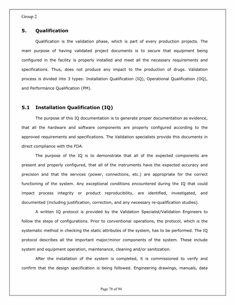
Group 2
Page 78 of 94
5. Qualification
Qualification is the validation phase, which is part of every production projects. The
main purpose of having validated project documents is to secure that equipment being
configured in the facility is properly installed and meet all the necessary requirements and
specifications. Thus, does not produce any impact to the production of drugs. Validation
process is divided into 3 types: Installation Qualification (IQ), Operational Qualification (OQ),
and Performance Qualification (PM).
5.1 Installation Qualification (IQ)
The purpose of this IQ documentation is to generate proper documentation as evidence,
that all the hardware and software components are properly configured according to the
approved requirements and specifications. The Validation specialists provide this documents in
direct compliance with the FDA.
The purpose of the IQ is to demonstrate that all of the expected components are
present and properly configured, that all of the instruments have the expected accuracy and
precision and that the services (power, connections, etc.) are appropriate for the correct
functioning of the system. Any exceptional conditions encountered during the IQ that could
impact process integrity or product reproducibility, are identified, investigated, and
documented (including justification, correction, and any necessary re-qualification studies).
A written IQ protocol is provided by the Validation Specialist/Validation Engineers to
follow the steps of configurations. Prior to conventional operations, the protocol, which is the
systematic method in checking the static attributes of the system, has to be performed. The IQ
protocol describes all the important major/minor components of the system. These include
system and equipment operation, maintenance, cleaning and/or sanitization.
After the installation of the system is completed, it is commissioned to verify and
confirm that the design specification is being followed. Engineering drawings, manuals, data

Group 2
Page 79 of 94
sheets, and purchase orders is used to document proper installation and placement. An
evaluation is confirmed for proper connection and installation of supporting services and
components, such as filters, piping, valves, gauges, controls, etc., calibration scope for control,
monitoring (HMI), and recording instruments, such as pressure gauges, temperature sensor,
timers, differential pressure transmitter, etc. that could impact the efficacy, integrity and
quality of the product, that supports the system utilities, such as water, steam, electric, etc.

Group 2
Page 80 of 94
5.2 Operational Qualification (OQ)
The purpose of the Operational Qualification (OQ) is to demonstrate that the system
behaves as specified in the expected conditions and that its components are properly
integrated. After satisfactory completion of the system and/or equipment IQ execution, OQ is
performed to check the operational tests, measurements, and control tolerances of key
parameters that are critical for the proper operation of the system.
A written OQ protocol is implemented to test objectives, methodologies, and acceptance
criteria, which it involves in testing and measuring of the system’s key operational parameters
upon the execution. The operational data obtained from the instruments, indicators, gauges,
and sensor upon testing is monitored and evaluated. “Any "worse case" challenges to the
system/equipment are defined and incorporated into the testing strategy to challenge the
system/equipment capacity (Control)”.
Prior to the protocol execution of the OQ to all critical process instrumentations, all the
process, control, monitoring and recording instruments, such as pressure gauges, temperature
sensors, timers, etc., that could impact the product integrity, quality, or effectiveness are
calibrated. The calibration of the process instrumentation that is being used to gather the
qualification data is checked at the end of the study to establish confidence in qualification. Any
equipment found out of calibration at the end of a process validation study indicates that the
process has not been operating in a state of control and cannot be considered validated. Any
exceptional conditions encountered during the OQ are to be identified, investigated, and
documented (including justification, correction, and any necessary re-qualification studies).
Group 2
Page 81 of 94
5.3 Performance Qualification (PQ)
Performance Qualification is performed after a successful completion of the Installation
and Operational Qualifications (IQ/OQ) execution. Prior to execution, the test objectives,
methodologies, and acceptance are well defined in the PQ documentation. The purpose of the
PQ is to demonstrate if the system operating with input parameters produces the results that
satisfy the pre-established specification. In providing the assurance of the process, the critical
systems or processes requiring PQ is validated. This purpose is to test the ability of the system
or process to perform the intended function (over time) within the defined upper and lower
process variable limits. It is important that if OQ could be executed for system component, PQ
always must be done for complete system (Control).
The performance of the steam sterilization, crucial utility systems (HVAC, Purified USP
Water System), and cleaning and sanitization is being studied in PQ. A sufficient number of
replicate studies are performed to demonstrate the ability of the system/equipment to achieve
reproducible results. Testing may include analysis for chemical, physical, and microbiological
constituents. Any exceptional conditions encountered during the PQ will be identified,
investigated, and documented, which includes justification, correction, and any necessary re-
qualification studies (Control).

Group 2
Page 82 of 94
6. System Design

Group 2
Page 83 of 94
6.1 Structured Chart
1.0Translate
and TransferOperator
Command
3.0RetrieveReal-time
Data
8.0Update
Database
5.0ProduceReports
2.0Update User
Log File
7.0Create User
6.0Backup and
Restore
1.1TranslateOperatorCommand
1.2Authentic
ationProcess
1.3TransferOperatorCommand
1.2.1ReceiveLoginData
1.2.2VerifyUser
1.2.3Approve
Login
2.1Recieve
Request forUpdating
2.2Check
User LogFile
2.3Create
New LogFile
2.4Update
User Log
3.1TranslateOperator
Command
3.2Request
for Update
3.3ReceiveMachine
Data
3.4Display
Real-timeData
4.0ControlMachine
4.1TranslateOperatorCommand
4.2Request for
Update
4.3TransferControl
Command
5.1Retrieve
Dataand Transfer
5.2Produce
UserReports
5.3ProduceMachineReports
5.4Generate
ManagementReports
6.1TransferRequest
6.2Backup
Database
6.3Restore
Database
7.1Receive
New UserInformation
7.2Verify New
User
7.3Update
User DataFile
Operator Commands
Request
Operator Commands
Login Data
Login Data
Login Data
User Name UserName
Current User Data
Request for Update
Current User Data
UserData Request
Formmatted User Data
Operator Commands
Operator Commands
Update DataCommands Machine Data Realtime Data
Operator Commands
Realtime Data
Operator Commands
Commands UserData
Command Request
Machine Data
User Data
User DataMachine Data
User Report MachineReport
Reports
Management Report
System Commands
System Commands
Commands RequestBackup
RequestRestore
User Data
User Data
New User Info.Request forVerification
New User Info.
User Data
Requestfor Update
USER DATAFILE ISQL
Update Info.
New User Info.
USER LOG FILE
Formmatted User Data

Group 2
Page 84 of 94
User Interface Design
6.1.1 AS-IS User Interface Design

Group 2
Page 85 of 94

Group 2
Page 86 of 94
6.3.2 TO-BE User Interface Design
See Attached

Group 2
Page 87 of 94
6.2 Database Design
6.2.1 AS-IS Database Design
The “InSQL Service Control” utility was launched to start the InSQL Server:
Pressed “GO”, and then “Yes” to confirm the start:

Group 2
Page 88 of 94
The following shows all services started up with no errors:
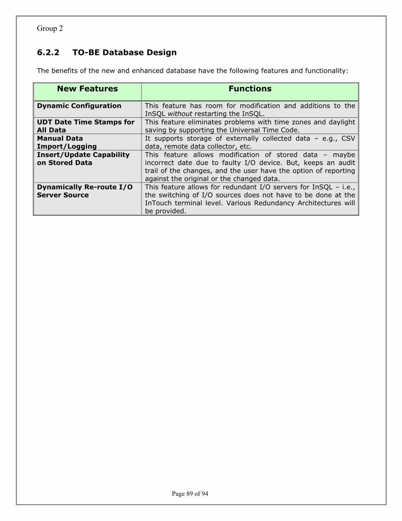
Group 2
Page 89 of 94
6.2.2 TO-BE Database Design
The benefits of the new and enhanced database have the following features and functionality:
New Features Functions
Dynamic Configuration This feature has room for modification and additions to the InSQL without restarting the InSQL.
UDT Date Time Stamps for All Data
This feature eliminates problems with time zones and daylight saving by supporting the Universal Time Code.
Manual Data Import/Logging
It supports storage of externally collected data – e.g., CSV data, remote data collector, etc.
Insert/Update Capability on Stored Data
This feature allows modification of stored data – maybe incorrect date due to faulty I/O device. But, keeps an audit trail of the changes, and the user have the option of reporting against the original or the changed data.
Dynamically Re-route I/O Server Source
This feature allows for redundant I/O servers for InSQL – i.e., the switching of I/O sources does not have to be done at the InTouch terminal level. Various Redundancy Architectures will be provided.

Group 2
Page 90 of 94
7. System Architectural Method
7.1 System Architectural Method (AS-IS Model)
New Production Network
SQL Server Workstation Industrial SQL Server Terminal Server
Router
System Architectural Design
Network Controllers(previously installed)
Network Controller(new)
Bus Hub
Field Controllers(previously installed)

Group 2
Page 91 of 94
7.2 System Architectural Method (TO-BE Model)
New Production Network
SQL Server Workstation Industrial SQL Server Terminal Server
Router
Network Controllers(previously installed)
Network Controller(new)
Bus Hub
Field Controllers(previously installed)
Bus Hub (New)
Field Controllers (New)
(Project Proposed)
HMI HMI
HMI
HMI HMIHMIHMI
HMIHMI HMI HMIHMI

Group 2
Page 92 of 94
8. References
Mody, Rashesh. From Buttons & Dials to Object-Oriented Graphics & Portals: A Short History of
the Windows-Based Human Machine Interface. IAN Instrumentation & Automation News. p.5.
(eds) October 2002
Verma, Harsh, Ph.D. Lecture on UML and Use Cases for Object-oriented Analysis. MIT E-
Commerce Architecture Project. 2002
IEEE Std 1074-1991. IEEE Standard for Developing Life Cycle Processes. New York, NY:
Institute of Electrical and Electronics Engineers, 1991.
Institute of Electrical and Electronics Engineers. IEEE Standard Computer Dictionary: A
Compilation of IEEE Standard Computer Glossaries. New York, NY: 1990.
IRIS Networks of Centres of Excellence Project Proposal. Human-Machine Interfaces Theme.
October 2000.
Caron, Richard. System Features Description v1.0 Final. Building Management Systems. 22
April 2002.
Caron, Richard. Required Specification for Purchased System v1.0 Final. Building Management
Systems. 20 May 2002.
Evans, Michael W. & Marciniak, John. Software Quality Assurance and Management. New York,
NY: John Wiley & Sons, Inc., 1987.
IRIS Networks of Centres of Excellence Project Proposal. Human-Machine Interfaces Theme.
October 2000.
Kim, Porter. Package Configuration Specification v1.0 Final. Monsen Engineering Company. 16
September 2002.
Mody, Rashesh. From Buttons & Dials to Object-Oriented Graphics & Portals: A Short History of
the Windows-Based Human Machine Interface. IAN Instrumentation & Automation News. p.5.
(eds) October 2002.

Group 2
Page 93 of 94
Povanda, Thomas, Eng. Industrial SQL Server Version 8.0. PF Laboratories BMS Upgrade
Project. 2002.
Pressman, Roger S. Software Engineering: A Practitioner’s Approach, 5th edition. 2001
Rusyniak, John M. MP-6 Fluid Bed Processor Operation and Maintenance Manual. Niro
Incorporated. Columbia, MD. September 1999. Rev. 0.
Verma, Harsh, Ph.D. Lecture on UML and Use Cases for Object-oriented Analysis. MIT E-
Commerce Architecture Project. 2002.
Wonderware FactorySuite InTouch 7.1/7.11 User Guide, Rev. C, July 1999.
Wonderware FactorySuite InTouch 7.1/7.11 Reference Guide, Rev. C, July 1999.
Wonderware FactorySuite IndustrialSQL Server Administration Guide, Rev. A, 15 May 2002.
Wonderware FactorySuite IndustrialSQL Server Database Reference, Rev. A, 15 May 2002.
Wonderware MaintenanceSuite Introduction, PN 06-2077, March 2000.
http://www.rspa.com/spi/glossary.html
http://agilemanifesto.org/principles.html
http://www.extremeprogramming.org/what.html
http://www.agilealliance.org/articles/articles/IntroToXpTomKubit.pdf
http://www.inf.vtt.fi/pdf/publications/2002/P478.pdf
http://www.db.stanford.edu/~burback/watersluice/node69.html
http://www.jodypaul.com/SWE/LCM/index.html

Group 2
Page 94 of 94
9. Extra Work
Title Quantity Page
Introduction: 1 History 6 Project Planning: 1 Previous Works 11 Methodologies: 3 Extreme Programming (XP) – Agile Approach 17 WINWIN Spiral Model 19 Methodology Selection Matrix 20 Documenting Requirements: 2 Functional Requirements 54 Non-Functional Requirements 55 System Specifications: 2 Functional Specification 77 Design Specification 78 Qualifications: 3 Installation Qualification (IQ) 79 Operational Qualification (OQ) 81 Performance Qualification (PQ) 82 System Design: 2 User Interface Design 85 Database Design 89 System Architectural Model: 2 AS-IS System Architectural Model 90 TO-BE System Architectural Model 91