Embed Size (px)
Citation preview

Lab Manual
Computer Communication
Network
Department of Electronics & Telecommunication Engineering
St. Vincent Pallotti College of Engineering & Technology

CCN Lab Manual SVPCET
1
Experiment 1
Study of CCN components
Aim: To study Network Hardware components – Cables, NIC, Repeaters, Hubs, Bridges,
Switches, Routers and Gateway.
Equipments:
1. Cables - Patch Cables, Rollover Ethernet Cable, Unshielded Twisted Pair (UTP) Cable,
Shielded Twisted Pair (STP), Serial Cable, Optical Fiber
2. NIC
3. Repeater
4. Hub
5. Bridge
6. Switch
7. Router
8. Gateway
Theory:Cables:1. Patch CablesA patch cable connects two network devices. Patch cables are typically CAT5 / CAT5e/Cat6Ethernet cables linking a computer to a nearby network hub, switch or router. The connector iscalled RJ45. Ethernet patch cables are useful to those building home computer networks and alsoto travelers who need wired access to Internet connections. They are normally manufacturedusing stranded rather than solid conductors in order to give them pliability that reduces risk ofbreakage when unplugging or carrying them.
CAT5 Standard Patch Cord

CCN Lab Manual SVPCET
2
10 BASE T represents 10 Mbps Baseband signalling Twisted pair cable. Other options are, 100BASE T, 1000 BASE T. For 10 Base T and 100 Base T only 4 pins are used. 1000 Base T uses 4pairs and uses all pins and CAT6 cable is required.2. Rollover Ethernet Cable:A crossover cable directly connects two network devices of the same type to each other overEthernet. Ethernet crossover cables are commonly used when temporarily networking twodevices in situations where a network router, switch or hub is not present.
3. Unshielded Twisted Pair (UTP) Cable:Twisted pair cabling comes in two varieties: shielded and unshielded. Unshielded twisted pair(UTP) is the most popular and is generally the best option for school networks. The quality ofUTP may vary from telephone-grade wire to extremely high-speed cable. The cable has fourpairs of wires inside the jacket. Each pair is twisted with a different number of twists per inch tohelp eliminate interference from adjacent pairs and other electrical devices. The tighter thetwisting, the higher the supported transmission rate and the greater the cost per foot. TheEIA/TIA (Electronic Industry Association/Telecommunication Industry Association) hasestablished standards of UTP and rated six categories of wire.
Unshielded Twisted Pair (UTP) Cable

CCN Lab Manual SVPCET
3
4. Shielded Twisted Pair (STP):Although UTP cable is the least expensive cable, it may be susceptible to radio and electricalfrequency interference (it should not be too close to electric motors, fluorescent lights, etc.). Ifyou must place cable in environments with lots of potential interference, or if you must placecable in extremely sensitive environments that may be susceptible to the electrical current in theUTP, shielded twisted pair may be the solution. Shielded cables can also help to extend themaximum distance of the cables. Shielded twisted pair cable is available in three differentconfigurations. Each pair of wires is individually shielded with foil. There is a foil or braid shieldinside the jacket covering all wires (as a group). There is a shield around each individual pair, aswell as around the entire group of wires (referred to as double shield twisted pair).
Shielded Twisted Pair (STP)
5. Serial Cable:This port connects a PC to an external modem, serial mouse, etc. DOS calls these ports COM1-COM4. The small version is slightly more popular than the large version. Both the small (maleDB-9) and large (male DB-25) versions are electrically identical, and can be interchanged with asimple adapter. They both speak RS-232, a relatively slow (around 105Kbps max) and error-prone protocol. The default controller is CPU-intensive and low data rate. A better UART,common on modern machines, is the 16550A, which has a 1KB buffer.
Serial Cable
6. Optical Fiber:

CCN Lab Manual SVPCET
4
Fiber optic cabling consists of a centre glass core surrounded by several layers of protectivematerials. A plastic coating then cushions the fiber centre help to strengthen the cables andprevent breakage. It transmits light rather than electronic signals eliminating the problem ofelectrical interference. This makes it ideal for certain environments that contain a large amountof electrical interference. It has also made it the standard for connecting networks. Fiber opticcables have the ability to transmit signals over much longer distances than coaxial and twistedpair. It also has the capability to carry information at vastly greater speeds. This capacitybroadens communication possibilities to include services such as video conferencing andinteractive services. The cost of fiber optic cabling is comparable to copper cabling.
Optical Fiber
NIC – Network Interface Card:
A network card, network adapter or NIC (network interface card) is a piece of computer hardwaredesigned to allow computers to communicate over a computer network. It provides physical access to anetworking medium and often provides a low-level addressing system through the use of MACaddresses. It allows users to connect to each other either by using cables or wirelessly. The NIC providesthe transfer of data in megabits. On modern PCs, NIC is integrated into the motherboard.
Repeater:

CCN Lab Manual SVPCET
5
A repeater is an electronic device that receives a signal and retransmits it at a higher power level,or to the other side of an obstruction, so that the signal can cover longer distances withoutdegradation. In most twisted pair Ethernet configurations, repeaters are required for cable runslonger than 100 meters away from the computer.
Repeater
Hub:
A hub contains multiple ports. When a packet arrives at one port, it is copied to all the ports ofthe hub for transmission. When the packets are copied, the destination address in the frame doesnot change to a broadcast address. It does this in a rudimentary way: It simply copies the data toall of the Nodes connected to the hub.
Hub
Bridge:
A network bridge connects multiple network segments at the data link layer (layer 2) of the OSIModel. Bridges do not promiscuously copy traffic to all ports, as hubs do, but learn which MACaddresses are reachable through specific ports. Once the bridge associates a port and an address,it will send traffic for that address only to that port. Bridges learn the association of ports andaddresses by examining the source address of frames that it sees on various ports. Once a framearrives through a port, its source address is stored and the bridge assumes that MAC address isassociated with that port. The first time that a previously unknown destination address is seen,the bridge will forward the frame to all ports other than the one on which the frame arrived.
Bridges come in three basic types:

CCN Lab Manual SVPCET
6
1. Local bridges: Directly connect local area networks (LANs)2. Remote bridges: Can be used to create a wide area network (WAN) link between LANs.
Remote bridges, where the connecting link is slower than the end networks, largely havebeen replaced by routers.
3. Wireless bridges: Can be used to join LANs or connect remote stations to LANs.
Bridge
Switch:
A switch is a device that forwards and filters OSI layer 2 datagram between ports based on theMAC addresses in the packets. This is distinct from a hub in that it only forwards the datagramto the ports involved in the communications rather than all ports connected. A switch is notcapable of routing traffic based on IP address (layer 3) which is necessary for communicatingbetween network segments or within a large or complex LAN. Some switches are capable ofrouting based on IP addresses but are still called switches. A switch normally has numerousports, with the intention being that most or the entire network is connected directly to the switch,or another switch that is in turn connected to a switch. Switch is a marketing term thatencompasses routers and bridges, as well as devices that may distribute traffic on load or byapplication content (e.g., a Web URL identifier). Switches may operate at one or more OSImodel layers, including physical, data link, network, or transport (i.e., end-to-end).
Switch
Router:
CCN Lab Manual SVPCET
7
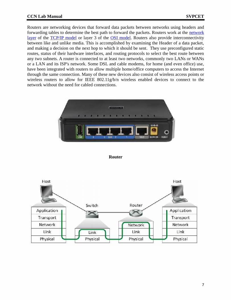
Routers are networking devices that forward data packets between networks using headers andforwarding tables to determine the best path to forward the packets. Routers work at the networklayer of the TCP/IP model or layer 3 of the OSI model. Routers also provide interconnectivitybetween like and unlike media. This is accomplished by examining the Header of a data packet,and making a decision on the next hop to which it should be sent. They use preconfigured staticroutes, status of their hardware interfaces, and routing protocols to select the best route betweenany two subnets. A router is connected to at least two networks, commonly two LANs or WANsor a LAN and its ISP's network. Some DSL and cable modems, for home (and even office) use,have been integrated with routers to allow multiple home/office computers to access the Internetthrough the same connection. Many of these new devices also consist of wireless access points orwireless routers to allow for IEEE 802.11g/b/n wireless enabled devices to connect to thenetwork without the need for cabled connections.
Router

CCN Lab Manual SVPCET
8
Gateway:
Gateway is used to connect independent networks. A gateway is a protocol convertor. It operatesin all the 7 layers of OSI Model. A gateway can accept a packet formatted for one protocol (ex:TCP/IP) and convert it to a packet formatted for another protocol (ex: Apple Talk) beforeforwarding it. The gateway must adjust the data rate, size and data format. Gateway is generallysoftware installed within a router. It also requires the establishment of mutually acceptableadministrative procedures between both networks. A protocol translation/mapping gatewayinterconnects with different network protocol technologies by performing required protocolconversions.
Result:- Thus we have studied Network Hardware components – Cables, NIC, Repeaters,Hubs, Bridges, Switches and Routers.
Conclusion: From this experiment we came to understand the use of different networkcomponents is based on the type of Network, type of applications, services beingimplemented.
CCN Lab Manual SVPCET
9
Viva Question:
1. What is the purpose of cables being shielded and having twisted pairs?
2. What advantages does optical fiber have over other media?
3. When you move the NIC cards from one PC to another PC does MAC address getstransferred as well?
4. What is the expression of potential gradient of a current carrying cable? Explain it withdetailed expression.

CCN Lab Manual SVPCET
1
Experiment 2
Command line utilities
Aim: To demonstrate data transmission using Ping protocol, tracert and examine IPconfiguration. Study of NAT and DHCP.
Equipments (Software): Command Prompt
IP Configuration:
Each host machine is identified by its IP Address on the network. To know the configuration ofmachine “ipconfig” command is used. In linux, we use "ifconfig" command or "nmcli devlist" command.Type “ipconfig” at command prompt and press Enter. The screen will show the 4 byte IPv4address, 16 byte IPv6 address, subnet mask, 6 byte MAC address and default gateway for thecomputer’s connection. Subnet mask divides the IP address into network number and a hostnumber within network. The default Gateway is a host which connects the local network to theoutside world. It should be in the same network or subnet, otherwise this host would not be ableto communicate outside the network. If the subnet mask is 255.255.255.0, it The tells us that thefirst three octets of the IP address are network number. Thus first three octets of IP address ofevery host must match the first three octets of IP address of Gateway. Subnet mask can also bewritten in CIDR notation e.g. /8 means first 8 bits are 1, i.e. 255.0.0.0.IPv6 address is written a 4 groups of 4 hex digits. The range fe80::/10 is for local link. %11 atend of IPv6 address indicates NIC id of 11.All addressing within a network is done on the basis of MAC address.
Compare your results with the results of neighboring computers in the lab.
To check more details of the configuration type:
ipconfig /all

CCN Lab Manual SVPCET
2
DHCP - Dynamic Host Configuration Protocol
The internet Service Provider gives a range of IP addresses to a customer and the customerassigns them to the individual hosts in his network. If the addresses are permanently assigned,they are called static IP addresses. To relieve the burden of manually assigning IP addresses andavoiding duplicate address problems we use a DHCP server which dynamically allots an IPaddress to a host when it logs in. This method is followed for DSL networks.
NAT - Network Address Translator
If the number of hosts in a network is much larger than the IP addresses provided by the ISP, thenwe assign local addresses in the range 192.168 range to the hosts and use a NAT to translatethese to one of the actual IP addresses when sending a message to outside world. To demonstratethis, type "whatismyip.com" in the internet browser. The website displays the actual IP address.Observe that it is different. Compare it with the result of neighboring computers in the lab.
Ping:Ping command is basically used to check whether a particular machine in the network is alive ordisconnected. Ping command basically sends ICMP ECHO REQUEST packets to the specifiedhost. If the host responds, you get an ICMP Packet back.
Procedure:
Follow these steps:1. Log on to the host computer as Administrator or as Owner.
2. Click Start, and then click Run.
3. In Run type “cmd” to invoke the command prompt.Other way is to Click Start then Programs Accessories Command Prompt
4. In Command Prompt type:ping <IP Address of the System you want to check >
Use the address of a neighboring computer in the lab as discovered with ipconfigcommand.
ex: ping 192.168.43.60

CCN Lab Manual SVPCET
3
If one wants to check continuously then following command should be used:ping 192.168.43.60 –t
To terminate the continuous ping, press “ctrl+c”.
We can ping directly to any website as well. Type ping, space and www.cisco.com, then pressEnter.ping www.cisco.com
Notice the outputs. A DNS server will resolve the name to an IP address and the ping will besuccessful only in the existence of the DNS server.

CCN Lab Manual SVPCET
4
Traceroute:
Traceroute(Tracert in windows) is a command which shows the path through which the packetwill travel from your computer system to the one you specify. It will list all the routers it passesthrough until it reaches its destination, or fails to and is discarded. In addition it will giveinformation about the number of Hops and time taken by each hop from router to router.
Algorithm:
The traceroute program sends a ping command to the destination with TTL =1. So it is rejectedby the first router in the path and it sends a failure notification using ICMP protocol. Thus we getid of first router. Then the ping command is repeated with TTL = 2. Now it is rejected by thesecond router. This process is repeated till we reach the destination or 30 hops occur.
Follow these steps for windows:1. Log on to the host computer as Administrator or as Owner.
2. Click Start, and then click Run.
3. In Run type “cmd” to invoke the command prompt.Other way is to Click Start then Programs Accessories Command Prompt
4. In Command Prompt type:tracert <IP Address of the System you want to check >
ex: tracert 192.168.43.60In linux,at command prompt, type tracerout ibm.com
This shows that the trace command will check up to 30 hops maximum for the packet to reach tothe specified machine. If the machine is on the same network then no. of hops=1. If the specifiedmachine is on other network then it will show number of hops and time taken by each hop.
If the machine is unreachable then it will try out for maximum 30 hops as shown below:

CCN Lab Manual SVPCET
5
Even we can trace route to a website as well. Type following command and observe the output.tracert www.cisco.comARP
Address Resolution Protocol is used get MAC address of a computer having a given IP address.At command prompt, typearp -aThe terminal shows pairs of IP address and MAC address.Result:- Thus we have studied the basic network commands such ping, traceroute, ipconfigand arp.
The results are as follows.
My IP Address

CCN Lab Manual SVPCET
6
My MAC addresses
My Default gateway
My Subnet mask
My IP address translated by NAT
My DNS Server IP address
Ping for destination IP addresses
Traceroute for destination IP addresses
Conclusion: From this experiment we came to understand how to check whether a node is
connected or disconnected using “ping” command, how to find the intermediate
routers and number of hops using “tracert” command and how to find out the IP
configuration of a machine using “ipconfig” command.

CCN Lab Manual SVPCET
7
Viva Question:
1. What is MAC address and IP address ? Why IP address is required?
2. What is NDP? What is the difference between ARP and NDP?
3. What is the difference between IPV4 and IPV6?
4. What is NAT? Explain with an practical example?
5. What is the peer to peer process and Round Trip Time?

CCN Lab Manual SVPCET
1
Experiment 3
NS2 introduction and creation of two node network
Aim: To study Network Simulator “ns-2” and perform simulation of 2 Nodes in “ns-2”.
Equipments (Software): ns-2, NAM
Theory:
ns-2 :
The Network Simulator version 2 (NS-2) is a deterministic discrete event network simulator,initiated at the Lawrence Berkeley National Laboratory (LBNL) through the DARPA fundedVirtual Internetwork Test bed (VINT) project. The VINT project is collaboration between theInformation Sciences Institute (ISI) at the University of Southern California (USC), Xerox's PaloAlto Research Centre (Xerox PARC), University of California at Berkeley (UCB) and LBNL.NS-2 was initially created in 1989 as an alternative to the REAL Network Simulator. Since thenthere is significant growth in uses and width of NS project. Although there are several differentnetwork simulators available today, ns-2 is one of the most common. NS-2 differs from most ofthe others by being open source software, supplying the source code for free to anyone thatwants it.
Structure of ns-2:
NS-2 is made up of hundreds of smaller programs, separated to help the user sort through andfind what he or she is looking for. Every separate protocol, as well as variations of the same,sometimes has separate files. Some are simple, but still dependent on the parental class.
C++:
C++ is the predominant programming language in ns-2. It is the language used for all the smallprograms that make up the ns-2 hierarchy. C++, being one of the most common programminglanguages and specially designed for object- oriented coding, was therefore a logical choice what

CCN Lab Manual SVPCET
2
language to be used. This helps when the user wants to either understand the code or do somealterations to the code. There are several books about C++ and hundreds, if not thousands, ofpages on the Internet about C++ simplifying the search for help or answers concerning the ns-2code.
OTcl:
Object Tcl (OTcl) is object-oriented version of the command and syntax driven programminglanguage Tool Command Language (Tcl). This is the second of the two programming languagesthat NS-2 uses. The front-end interpreter in NS-2 is OTcl which link the script type language ofTcl to the C++ backbone of NS-2. Together these two different languages create a scriptcontrolled C++ environment. This helps when creating a simulation, simply writing a script thatwill be carried out when running the simulation. These scripts will be the formula for asimulation and is needed for setting the specifications of the simulation itself. Without a scriptproperly defining a network topology as well as the data-rows, both type and location, nothingwill happen.
Nodes:
A node can be either an end connection or an intermediate point in the network. All agents andlinks must be connected to a node to work. There are also different kinds of nodes based on thekind of network that is to be simulated. The main types are node and mobile node, where node isused in most wired networks and the mobile node for wireless networks. There are severaldifferent commands for setting the node protocols to be used, for instance what kind of routing isto be used or if there is a desire to specify a route that differs from the shortest one. Most of thecommands for node and mobile node can be easily found in the ns documentation. Nodes and theclosely connected link creating commands, like simplex link and duplex link, could beconsidered to simulate the behavior of both the Link Layer.
Agents:
An agent is the collective name for most of the protocols you can find in the transport layer. Inthe ns-2 documentation agents are defined as the endpoints where packets are created andconsumed. All the agents defined in ns-2, like tcp, udp etc., are all connected to their parentclass, simply called Agent. This is where their general behavior is set and the offspring classesare mostly based on some alterations to the inherent functions in the parent class. The modifiedfunctions will overwrite the old and thereby change the performance in order to simulate thewanted protocol. The agents are attached to nodes.
Applications:
The applications in ns-2 are related to the Application Layer in the TCP/IP suite. The hierarchyhere works in the similar way as in the agent’s case. To simulate some of the most importanthigher functions in network communication, the ns-2 applications are used. Since the purpose ofns-2 is not to simulate software, the applications only represent some different aspects of thehigher functions. Only a few of the higher layer protocols has been implemented, since some arequite similar when it comes to using the lower functions of the TCP/IP stack. For instance thereis no use adding both a SMTP and a HTTP application since they both use TCP to transfer smallamounts of data in a similar way. The only applications incorporated in the release version of ns-2 are a number of different traffic generators for use with UDP and telnet and FTP for using TCP.All the applications are script controlled and when concerning the traffic generators, you set the

CCN Lab Manual SVPCET
3
interval and packet-size of the traffic. FTP can be requested to send a data packet whenever theuser wants to, or to start a transfer of a file of arbitrary size. If starting an FTP transmission andnot setting a file-size the transmission will go on until someone calls a stop.
NAM:
The Network Animator NAM is a graphic tool to use with ns-2. It requires a nam-tracefilerecorded during the simulation and will then show a visual representation of the simulation. Thiswill give the user the possibility to view the traffic packet by packet as they move along thedifferent links in the network. NAM offers the possibility of tracing a single packet during itstravel and the possibility to move the nodes around for a user to draw up his network topologyaccording to his own wishes.
Network Animator GUI
Since the simulation has already been performed there is no possibility for the user to change thelinks or any other aspect of the simulation except the representation. The existence of an X-

CCN Lab Manual SVPCET
4
server allows NAM to be able to open a graphical window. Therefore if NAM is to work, theremust be a version of X-server running.
Simulating two node system
Algorithm:
1. Create a new simulator object and open trace files.2. Define a ’finish’ procedure –to flush trace record in the trace and trace output files.3. Create 2 nodes named n0 and n1.4. Set a link between n0 and n1.5. Create a UDP agent and Null agent.6. Attach the UDP agent to n0 and Null agent to n1.7. Attach CBR type FDP agent to UDP.8. Start the bit generator at .5 sec and stop it at 2.5 Sec.9. Trace the protocols using CBR.10. Run the simulation.
Program in OTCL:
Open gedit, create following file and name it “expt3.tcl”. Comment line is indicated by # in first place.
#Define a new simulator objectset ns [new Simulator]#Open file named out.tr for writing with File handle = file1set file1 [open out.tr w]# Direct all trace output to file 1$ns trace-all $file1#Open file named out.nam for writing with File handle = file2set file2 [open out.nam w]# Direct all animator output to file 2$ns namtrace-all $file2#Define finish processproc finish {} {# Flush and close filesglobal ns file1 file2$ns flush-traceclose $file1close $file2
# Start nam for displaying data in nam.outexec nam out.nam &exit 0
}#Define nodes n0 and n1set n0 [$ns node]set n1 [$ns node]#Define a duplex link between n0 and n1 with .3 Mb bandwidth and drop trail queue$ns duplex-link $n0 $n1 0.3Mb 10ms DropTail#Define a UDP agent named udp

CCN Lab Manual SVPCET
5
set udp [new Agent/UDP]#Attach agent to n0$ns attach-agent $n0 $udp#Define a null agent named sink. It sends ACK packets to originator.set sink [new Agent/Null]#Attach agent to n0$ns attach-agent $n1 $sink#Connect the agents. They will find path automatically.$ns connect $udp $sink#Set Constant Bitrate Generator named ftpset ftp [new Application/Traffic/CBR]#Attach generator to udp agent$ftp attach-agent $udp#Start bit generator ftp at t=0$ns at 0.5 "$ftp start"#Stop bit generator ftp at t=2.5 sec$ns at 2.5 "$ftp stop"#Execute "finish" procedure at t= 3 sec$ns at 3 "finish"#Run the script$ns run
Output:
To run the above program, invoke NS2 by typing ns on a terminal. Terminal displays %. Then type,
ns expt3
The program runs simulation and then invokes NAM window.
When you click on the 'play' button in the nam window, you will see that after 0.5 simulation seconds,node 0 starts sending data packets to node 1. You might want to slow nam down then with the 'Step'slider. click on any packet in the nam window to monitor it, and you can also click directly on the link toget some graphs with statistics. Change the 'packetsize_' and 'interval_' parameters in the Tcl script withfollowing statements.
$ftp set packetSize_ 500$ftp set interval_ 0.005
Trace file
Open out.tr in editor and examine the contents. The format is as follows.
1. EVENT OR TYPE IDENTIFIER
+ :a packet enque event- :a packet deque eventr :a packet reception eventd :a packet drop (e.g., sent to dropHead_) eventc :a packet collision at the MAC level

CCN Lab Manual SVPCET
6
2. TIME : at which the packet tracing string is created.3-4. SOURCE AND DESTINATION NODE : source and destination ID's of tracing objects.5. PACKET NAME : Name of the packet type.6. PACKET SIZE : Size of packet in bytes.7. FLAGS : 7 digit flag string.(Not used)8. FLOW ID9-10. SOURCE AND DESTINATION ADDRESS : The format of these two fields is “a.b”, where “a" isthe address and "b" is the port.11. SEQUENCE NUMBER12. PACKET UNIQUE IDResult:- Thus we have studied basics and performed the simulation of 2 nodes in NetworkSimulator “ns-2”
Conclusion: From this experiment we came to understand creation of nodes, linking of nodesand assigning traffic on this link. Also we understand writing the simple oTclscript and its simulation using ns-2.

CCN Lab Manual SVPCET
7
Viva Question:
1. What protocols does NS support?
2. How do you get IP address of the node in NS2 and where is the IP address stored?
3. What is the address format in NS2?
4. What is the difference between OPNET and NS2?
CCN Lab Manual SVPCET
1
Experiment 4
Study of 4 node topology using TCP and UDP protocol.
Aim: To implement Transmission Control Protocol (TCP) and User Datagram Protocol (UDP)using NS2.
Equipments (Software): ns-2, NAM
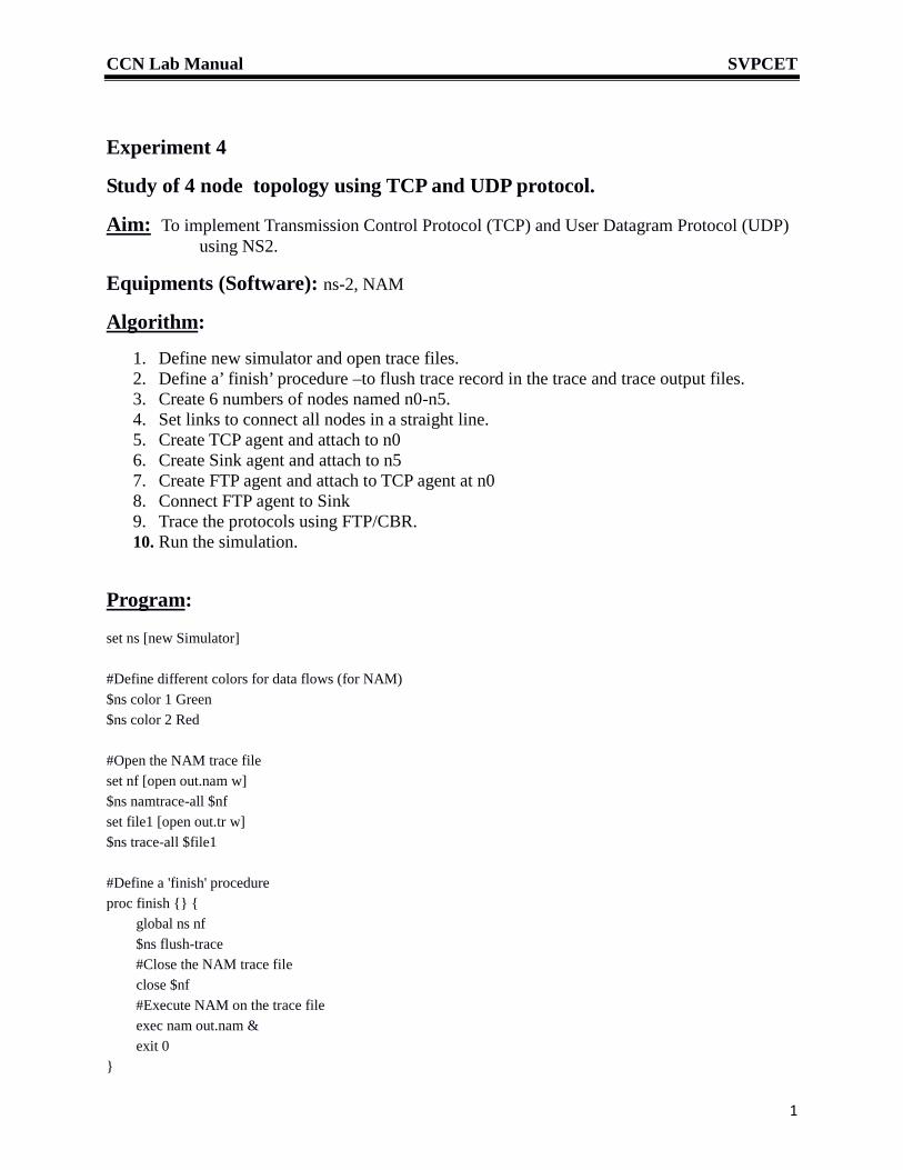
Algorithm:
1. Define new simulator and open trace files.2. Define a’ finish’ procedure –to flush trace record in the trace and trace output files.3. Create 6 numbers of nodes named n0-n5.4. Set links to connect all nodes in a straight line.5. Create TCP agent and attach to n06. Create Sink agent and attach to n57. Create FTP agent and attach to TCP agent at n08. Connect FTP agent to Sink9. Trace the protocols using FTP/CBR.10. Run the simulation.
Program:
set ns [new Simulator]
#Define different colors for data flows (for NAM)$ns color 1 Green$ns color 2 Red
#Open the NAM trace fileset nf [open out.nam w]$ns namtrace-all $nfset file1 [open out.tr w]$ns trace-all $file1
#Define a 'finish' procedureproc finish {} {
global ns nf$ns flush-trace#Close the NAM trace fileclose $nf#Execute NAM on the trace fileexec nam out.nam &exit 0
}

CCN Lab Manual SVPCET
2
#Create four nodesset n0 [$ns node]set n1 [$ns node]set n2 [$ns node]set n3 [$ns node]
#Create links between the nodes$ns duplex-link $n0 $n2 2Mb 10ms DropTail$ns duplex-link $n1 $n2 2Mb 10ms DropTail$ns duplex-link $n2 $n3 1.7Mb 20ms DropTail
#Set Queue Size of link (n2-n3) to 10$ns queue-limit $n2 $n3 10
#Give node position (for NAM)$ns duplex-link-op $n0 $n2 orient right-down$ns duplex-link-op $n1 $n2 orient right-up$ns duplex-link-op $n2 $n3 orient right
#Monitor the queue for link (n2-n3). (for NAM)$ns duplex-link-op $n2 $n3 queuePos .5
#Setup a TCP connectionset tcp [new Agent/TCP]#$tcp set class_ 2$ns attach-agent $n0 $tcpset sink [new Agent/TCPSink]$ns attach-agent $n3 $sink$ns connect $tcp $sink$tcp set fid_ 1
#Setup a FTP over TCP connectionset ftp [new Application/FTP]$ftp attach-agent $tcp#$ftp set type_ FTP
#Setup a UDP connectionset udp [new Agent/UDP]$ns attach-agent $n1 $udpset null [new Agent/Null]$ns attach-agent $n3 $null$ns connect $udp $null$udp set fid_ 2
#Setup a CBR over UDP connectionset cbr [new Application/Traffic/CBR]$cbr attach-agent $udp

CCN Lab Manual SVPCET
3
#$cbr set type_ CBR$cbr set packet_size_ 1000$cbr set rate_ 1mb#$cbr set random_ false
#Schedule events for the CBR and FTP agents$ns at 0.1 "$cbr start"$ns at 1.0 "$ftp start"$ns at 4.0 "$ftp stop"$ns at 4.5 "$cbr stop"
#Detach tcp and sink agents (not really necessary)#$ns at 4.5 "$ns detach-agent $n0 $tcp ; $ns detach-agent $n3 $sink"
#Call the finish procedure after 5 seconds of simulation time$ns at 5.0 "finish"
#Print CBR packet size and intervalputs "CBR packet size = [$cbr set packet_size_]"puts "CBR interval = [$cbr set interval_]"
#Run the simulation$ns run
Result:- Thus we have studied the Transmission Control Protocol (TCP) and User DatagramProtocol (UDP) using “NS -2”
Conclusion: From this experiment we came to understand creation of no. of nodes, creation ofTCP Agents, attaching these TCP Agents and UDP agents and its simulationusing ns-2.

CCN Lab Manual SVPCET
4
Viva Question:
1. What is droptail queue?
2. What is agent and what are types of agent?
3. What platform does NS run on and what kind of hardware do you need?
4. How to set transmission range in NS2?
5. How to get a node to sleep in NS2?
CCN Lab Manual SVPCET
1
Experiment 5
Socket programming in C
Aim: To write client and server program in C and perform data transfer between twocomputers using TCP/IP protocol.
Equipments (Software): gcc, gdb
Theory:
Sockets allow communication between two different processes on the same or
different machines. Socket consists of a pair of values: IP address and port
number. As several programs on a computer may be using a single IP address to
communicate, the port number identifies the program on a computer. To a
programmer, a socket looks and behaves much like a low-level file descriptor.
This is because commands such as read() and write() work with sockets in the
same way they do with files and pipes.
There are four types of sockets available to the users.
Stream Sockets − These sockets use TCP (Transmission Control Protocol)
for data transmission.
Datagram Sockets − They use UDP (User Datagram Protocol).
Raw Sockets − They are used by advanced level users.
Sequenced Packet Sockets − They are similar to a stream socket, withthe exception that record boundaries are preserved. They are also used
by advanced level users.
Socket library calls and data structures
The file sockets.h contains following structures.
struct sockaddr_in { //Use this for IP V4short sin_family; // e.g. AF_INET, AF_INET6unsigned short sin_port; // e.g. htons(3490)struct in_addr sin_addr; // struct in_addr is unsigned longchar sin_zero[8]; // zero this for normal use
};
struct sockaddr_storage { //Use this for IP V6 and accept functionuint8_t ss_len;sa_family_t ss_family;char ss_padding[SIZE];
}Common Functions
int socket (int family, int type, int protocol);/* Create a socket */

CCN Lab Manual SVPCET
2
int send(int sockfd, const void *msg, int len, int flags);
int recv(int sockfd, void *buf, int len, unsigned int flags);
int close( int sockfd );
htons(int a);/* Host to network byte order (short) */
Server Functions
int bind(int s, const struct sockaddr addr, socklen_t addrlen);/* bind to IP
&port*/
int listen(int s, int backlog);/* Wait for connect request from client */
int accept(int s, struct sockaddr addr, socklen_t addrlen);/ Accept client
request */
Client function
int connect(int s, const struct sockaddr *name, socklen_t namelen);
Procedure
Type client.c and server.c programs using gedit.
Compile them with
gcc -g client.c -o client.o
gcc -g server.c -o server.o
open a terminal and type
./server.out
The terminal should display
listening
Open another terminal and type
./client.out
The terminal should display
Hello world
The server terminal should display

CCN Lab Manual SVPCET
3
From client
SERVER PROGRAM
#include <stdio.h>
#include <sys/socket.h>
#include <netinet/in.h>
#include <string.h>
int main(){
int welcomeSocket, newSocket;
char buffer[1024];
struct sockaddr_in serverAddr;
struct sockaddr_storage serverStorage;
socklen_t addr_size;
/*---- Create the socket. The three arguments are: ----*/
/* 1) Internet domain 2) Stream socket 3) Default protocol (TCP in this
case) */
welcomeSocket = socket(PF_INET, SOCK_STREAM, 0);
/*---- Configure settings of the server address struct ----*/
/* Address family = Internet */
serverAddr.sin_family = AF_INET;
/* Set port number, using htons function to use proper byte order */
serverAddr.sin_port = htons(7891);
/* Set IP address to localhost */
serverAddr.sin_addr.s_addr = inet_addr("127.0.0.1");
/* Set all bits of the padding field to 0 */
memset(serverAddr.sin_zero, '\0', sizeof serverAddr.sin_zero);
CCN Lab Manual SVPCET
4
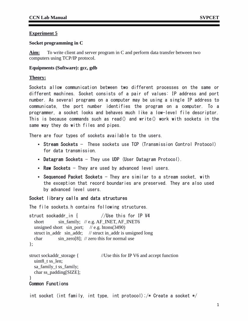
/*---- Bind the address struct to the socket ----*/
bind(welcomeSocket, (struct sockaddr *) &serverAddr, sizeof(serverAddr));
/*---- Listen on the socket, with 5 max connection requests queued ----*/
if(listen(welcomeSocket,5)==0)
printf("Listening\n");
else
printf("Error\n");
/*---- Accept call creates a new socket for the incoming connection ----*/
addr_size = sizeof serverStorage;
newSocket = accept(welcomeSocket, (struct sockaddr *) &serverStorage,
&addr_size);
/*---- Send message to the socket of the incoming connection ----*/
strcpy(buffer,"Hello World\n");
send(newSocket,buffer,13,0);
recv(newSocket, buffer, 1024, 0);
/*---- Print the received message ----*/
printf("Data received: %s",buffer);
return 0;
}
CLIENT PROGRAM
#include <stdio.h>
#include <sys/socket.h>
#include <netinet/in.h>
CCN Lab Manual SVPCET
5
#include <string.h>
int main(){
int clientSocket;
char buffer[1024];
struct sockaddr_in serverAddr;
socklen_t addr_size;
/*---- Create the socket. The three arguments are: ----*/
/* 1) Internet domain 2) Stream socket 3) Default protocol (TCP in this case) */
clientSocket = socket(PF_INET, SOCK_STREAM, 0);
/*---- Configure settings of the server address struct ----*/
/* Address family = Internet */
serverAddr.sin_family = AF_INET;
/* Set port number, using htons function to use proper byte order */serverAddr.sin_port = htons(7891);/* Set IP address to localhost */serverAddr.sin_addr.s_addr = inet_addr("127.0.0.1");/* Set all bits of the padding field to 0 */memset(serverAddr.sin_zero, '\0', sizeof serverAddr.sin_zero);/*---- Connect the socket to the server using the address struct ----*/
addr_size = sizeof serverAddr;
connect(clientSocket, (struct sockaddr *) &serverAddr, addr_size);
/*---- Read the message from the server into the buffer ----*/
recv(clientSocket, buffer, 1024, 0);
/*---- Print the received message ----*/
printf("Data received: %s",buffer);
strcpy(buffer,"From Client\r\n");
send(clientSocket,buffer,14,0);
send(clientSocket,buffer,strlen(buffer),0);
close( clientSocket);
CCN Lab Manual SVPCET
6
return 0;
}
Result:- Thus we have studied basics of TCP/IP socket programming.
Conclusion: We have successfully transmitted data between client and server.

CCN Lab Manual SVPCET
7
Viva Question:
1. What is socket?
2. HTTP is at which level in OSI model?
3. Which language is used to design webpage?
4. Mention some HTTP commands.
5. Which port is used for HTTP?

CCN Lab Manual SVPCET
8

CCN Lab Manual SVPCET
1
Experiment 6
Serial port programming in C
Aim: To write a C program to send a data stream and receive it in a terminal.
Equipments (Software): gcc, gdb, USB – TTL serial converter
Theory:
Serial ports have been traditionally used for communication between computers. Nowadays theyare replaced with USB ports. However serial port is still a very convenient device tocommunicate with embedded systems. Most modern computers do not have a serial port. So weuse a USB to TTL serial converter. If used with a modem, the port requires modem handshakesignals RTS, CTS, DTR and DSR. However these are not required for connecting an embeddedsystem using USB-serial converter. We need only 3 wires namely GND, TxD, RxD. We will dothe experiment in two stages.
1. Terminal to terminal
2 C program sends data to a terminal
The procedure is described below.
1. Terminal to terminal
We have to invoke two serial terminals from two linux terminals. Minicom is a popular terminalused in linux systems. It sends keyboard input on serial output and sends serial input to screen.Note that you must be logged in as a superuser.
Insert two USB-serial converters in a USB slots. The TxD RxD pins should be cross connected.To know that the converter is properly working, type
ls /dev | grep tty
In the list, ttyUSB0 and ttyUSB1 must be listed.
Then type minicom. It displays following message.
Welcome to minicom 2.3
OPTIONS: I18n
Compiled on Aug 19 2010, 05:48:57.

CCN Lab Manual SVPCET
2
Port /dev/ttyUSB0
Press CTRL-A Z for help on special keys
Open another terminal. By default, minicom is connected to ttyUSB0. We want the otherterminal to be connected to ttyUSB1. So invoke minicom with -s option(set up). Type :
minicom -s
The screen shows following message
+-----[configuration]------+
| Filenames and paths || File transfer protocols || Serial port setup || Modem and dialing || Screen and keyboard || Save setup as dfl || Save setup as.. || Exit || Exit from Minicom |+--------------------------+
Use down arrow keys to select Serial port setup and press ENTER
The screen now shows:
+-----------------------------------------------------------------------+
| A - Serial Device : /dev/ttyUSB0 |
| B - Lockfile Location : /var/lock |
| C - Callin Program : |
| D - Callout Program : |
| E - Bps/Par/Bits : 115200 8N1 |
| F - Hardware Flow Control : Yes |
| G - Software Flow Control : No |
| |

CCN Lab Manual SVPCET
3
| Change which setting? |
+-----------------------------------------------------------------------+
type A and change the serial device to /dev/ttyUSB1.
Press down arrow keys to select Exit.
Now both terminals are ready.
Type anything in first terminal and it will appear in the second terminal.
Now you can connect two different computers using the cross over serial cable and repeat theexperiment
2 C program sends data to a terminal
In this experiment we will write a C program to send a data stream to another terminal, eithersame computer or another computer.
Procedure and useful functions.
We need to open the serial terminal with "open" function.
fd = open("Serial port name", options);
We will use option O_RDWR for read write mode and O_NOCTTY to avoid this terminalbecoming controlling terminal of a linux process. The function returns an integer file descriptor.If fd is 1, then there is error in opening the serial port. The bytes to be sent are stored in a buffer.We use "write" function to send bytes.
int bytes written = write(fd, char* buffer, int length);
At the end, the file must be closed with close(fd) function.
The program is given below.
#include <stdio.h>#include <fcntl.h> /* File Control Definitions */#include <termios.h>/* POSIX Terminal Control Definitions*/#include <unistd.h> /* UNIX Standard Definitions */#include <errno.h> /* ERROR Number Definitions */void main(){
int fd;char write_buffer[] = "ABCDEFGH\r\n1234\r\n";int bytes_written = 0 ;fd = open("/dev/ttyUSB1",O_RDWR | O_NOCTTY);if(fd == 1)
printf("\n Error! in Opening ttyUSB0\n");else
printf("\n ttyUSB1 Opened Successfully\n");bytes_written = write(fd,write_buffer,sizeof(write_buffer));printf("%d Bytes written\r\n",bytes_written);

CCN Lab Manual SVPCET
4
close(fd);}The string ABCDEFGH1234 is displayed in the receiving terminal.
Receive program.
You may use following commands to receive data instead of using terminal.
struct termios SerialPortSettings;tcgetattr(fd, &SerialPortSettings);SerialPortSettings.c_cflag |= CREAD | CLOCAL;tcsetattr(fd,TCSANOW,&SerialPortSettings);char read_buffer[32];int bytes_read = 0;bytes_read = read(fd,&read_buffer,32);
Result:- Thus we have studied basics of serial port programming.
Conclusion: We have successfully transmitted data between sender and receiver.
CCN Lab Manual SVPCET
5
Viva Question:
1. What is the difference between UART and USART communication ?
2. Why baud rate is mentioned in serial communication?
3. What is null modem connection ?
4. ______ to increase the flexibility of the serial ports.a) The wires used for ports is changedb) The ports are made to allow different clock signals for input and outputc) The drivers are modifiedd) All of the above
5. The serial port is used to connect basically _____ and processor.a) I/O devicesb) Speakersc) Printerd) Monitor
CCN Lab Manual SVPCET
1
Experiment 7
Study of protocol analyser
Aim: To study internet traffic on a computer.
Equipments (Software): wireshark
Theory:
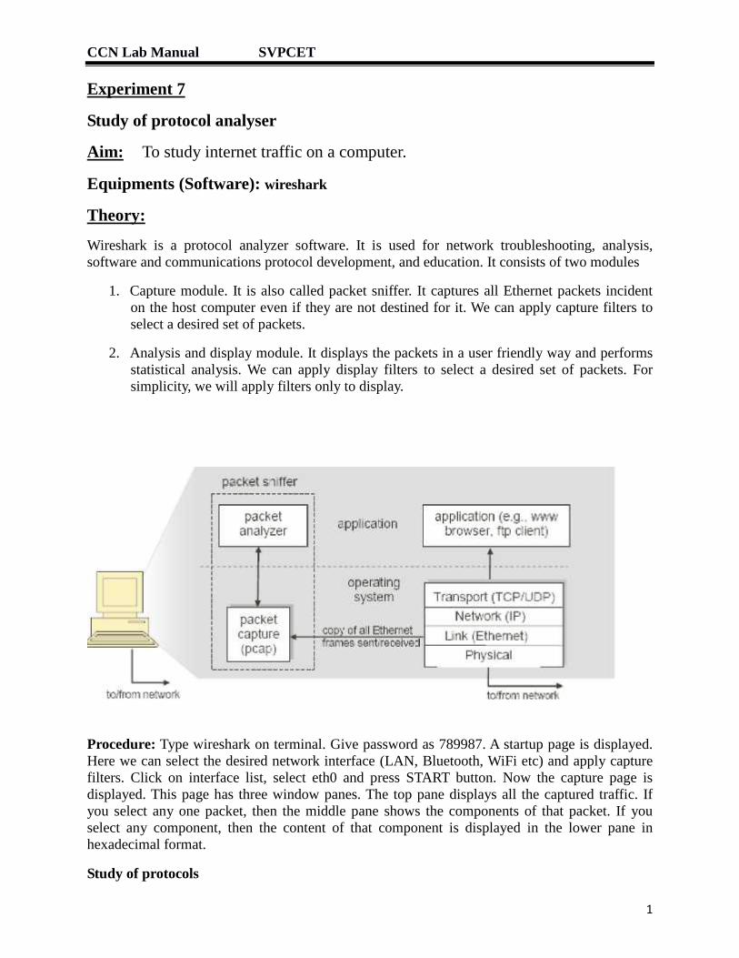
Wireshark is a protocol analyzer software. It is used for network troubleshooting, analysis,software and communications protocol development, and education. It consists of two modules
1. Capture module. It is also called packet sniffer. It captures all Ethernet packets incidenton the host computer even if they are not destined for it. We can apply capture filters toselect a desired set of packets.
2. Analysis and display module. It displays the packets in a user friendly way and performsstatistical analysis. We can apply display filters to select a desired set of packets. Forsimplicity, we will apply filters only to display.
Procedure: Type wireshark on terminal. Give password as 789987. A startup page is displayed.Here we can select the desired network interface (LAN, Bluetooth, WiFi etc) and apply capturefilters. Click on interface list, select eth0 and press START button. Now the capture page isdisplayed. This page has three window panes. The top pane displays all the captured traffic. Ifyou select any one packet, then the middle pane shows the components of that packet. If youselect any component, then the content of that component is displayed in the lower pane inhexadecimal format.
Study of protocols

CCN Lab Manual SVPCET
2
Open the browser, do some surfing and then press the button to stop capture. From menu, selectstatistics>Protocol hierarchy.
The statistics page shows percentage usage by various protocols. Since physical layer isEthernet, its usage is 100%. We can see ARP packets at Ethernet level. At IP level, we have IPV4and IPV6. Within each IP level, we have transport layer protocols TCP and UDP. We also haveICMP and IGMP at IP level. Following protocols are listed under UDP
SSDP : Simple Service Discovery Protocol (Advertize services like DNS, DHCP)
mDNS : Multicast Domain Name Server
LLMNR: Link Local Multicast Name Resolution(Used within campus)
DNS : Domain Name Server
Due to internet browsing, there are higher layer protocol packets like HTTP under TCP.
Note down the percentage traffic of main protocols and close the window.
Applying filters
The number of displayed packets is very large. We can select a desired type of packets byapplying display filters. Some useful filters are
http
tcp
udp
ip.src == 192.168.11.127
ip.dst == 192.168.11.127
ip.addr == 192.168.11.127
tcp.port == 80
eth.dst == ff:ff:ff:ff:ff:ff
We can combine filters with symbols &&, || and !.
arp && eth.addr == 00:22:FA:5A:96:1A
Study of ARP and ICMP protocols
Using ifconfig command, find your computer’s IP address and MAC address. Supposethey are 192.168.11.127 and 00:22:FA:5A:96:1A respectively. Note that the first threebytes, i.e. 00:22:FA represent NIC manufacturer, here IntelCor. Similarly find IPaddress and MAC address of your neighbor’s computer. Suppose they are192.168.11.112 and 00:17:7C:1D:2B:6C respectively. 00:17:7C represents Smartlin.Start capture. In terminal, give following command.
Ping 192.168.11.112
Abort the ping reply after 4-5 lines with ^C. Stop capture.

CCN Lab Manual SVPCET
3
Note that your computer must know the MAC address of the neighbor, so it has to sendARP request. It is broadcast on LAN. So we will apply a filter for ARP protocol and ourown MAC address as follows.
In wireshark window, apply filter as arp && eth.addr == 00:22:FA:5A:96:1A
You will find a line showing broadcast ARP request
“Who has 192.168.11.112 tell 192.168.11.127”Select this line in the top pane. Then select Ethernet II line in middle pane and observesource, destination and type ARP (0x0806).
Then select “Address resolution protocol (Request)” and observe the contents ofvarious fields in the lower pane.
There is ARP reply from 192.168.11.112 destined for IntelCor 5A:96:1A i.e.00:22:FA:5A:96:1A. This is not broadcast.
“192.168.11.112 is at 00:17:7C:1D:2B:6C”Select the line in top pane and observe the contents as explained above.
Now change the display filter to ICMP. You will observe some pairs of ping request andping reply. Select the ping request line. In middle pane select Ethernet II and observethat packet type is IPV4. In IP packet, observe that protocol is ICMP. Now select theInternet Control Message Protocol. Observe the contents of various fields in the lowerpane.
Study of TCP and HTTP protocols
Select the filter to http && ip.addr == 192.168.11.127.
Select the first entry. Usually it should be HTTP GET request. In middle pane, observe that it hasEthernet layer, IP layer, TCP layer and HTTP layer. Observe the contents of various fields.
Result:- Thus we have captured and displayed the internet traffic.
Conclusion: We have successfully decoded messages based on various protocols and observedtheir contents.

CCN Lab Manual SVPCET
4
Viva Question:
1 What are applications of protocol analyzer?
2 Which protocol is used by ping command? At which OSI layer is it situated?
3 How can you find the manufacturer of a NIC card?
4 How will you display only outgoing packets from your own terminal?
5 Explain ARP request and ARP reply.

CCN Lab Manual SVPCET
1
Experiment 8
Study of RSA encryption algorithm
Aim: To encrypt and decrypt a message using RSA algorithm.
Equipments (Software): gcc
Theory:
RSA is an algorithm used by modern computers to encrypt and decrypt messages. It is anasymmetric cryptographic algorithm. Asymmetric means that there are two different keys. This isalso called public key cryptography, because one of them can be given to everyone. The otherkey must be kept private. It is based on the fact that finding the factors of an integer is hard (thefactoring problem). RSA stands for Ron Rivest, Adi Shamir and Leonard Adleman, who firstpublicly described it in 1978. A user of RSA creates and then publishes the product of two largeprime numbers, along with an auxiliary value, as their public key. The prime factors must be keptsecret. Anyone can use the public key to encrypt a message, but with currently publishedmethods, if the public key is large enough, only someone with knowledge of the prime factorscan feasibly decode the message.
Key generation
Choose two different large random prime numbers p and q
Calculate n = pq e.g. p=61, q= 53, n=61*53=3233. Make sure that n is greaterthan the highest message value. For byte oriented message, n > 255. In practice, tis a very large value.
2. n is the modulus for the public key and the private keys.3. Calculate t= (p-1)(q-1) = 60*52=31204. Choose an integer e such that 1 < e < t , and e is coprime to e. ie: e and t share no
factors other than 1; gcd(e,t) = 1. Let e=17. e is kept as the private key exponent
5. Compute d such that de % t = 1. i.e. de = kt +1 for some integer k. try various values of d.For d=2753 and k=15, we get
2753*17 = 46801 = 15*3120 + 1. d is released as the public key exponent
Encryption
Cipher text c is created from plain text m with the formula:
c = me % n
Decryption
Plain text m is created from Cipher text c with the formula:
m = cd % n
As me is a very large number, in practice, the calculation is modified as follows. Starting withc=1, it is multiplied by m e times but after each multiplication, we replace the product with itsremainder with respect to n.

CCN Lab Manual SVPCET
2
3 way exchange scheme for safe key transfer
Suppose Bob wants to safely send public key db to Alice.
1 Bob encrypts db with his private key eb and sends to Alice on open network. m1 = dbeb
2 Alice further encrypts it with her own private key ea and sends to Bob. m2 = dbeb ea
3 Bob removes his encryption and sends message to Alice. m3 = dbea
Now Alice removes her encryption to get db.
C program
We will use p=17,q=23 for a byte long message.
n = 17*23 = 391. Note that 391 > 255.
t = (17-1)(23-1) = 352
Let e = 3.
Find d by brute force method of calculation. d is found as 235.
Check that de % t = (3*235) % 352 = 705 % 352 = 1
Note that encrypted message is calculated modulo 391, so it can be as large as 390. So we needan integer array to hold it.
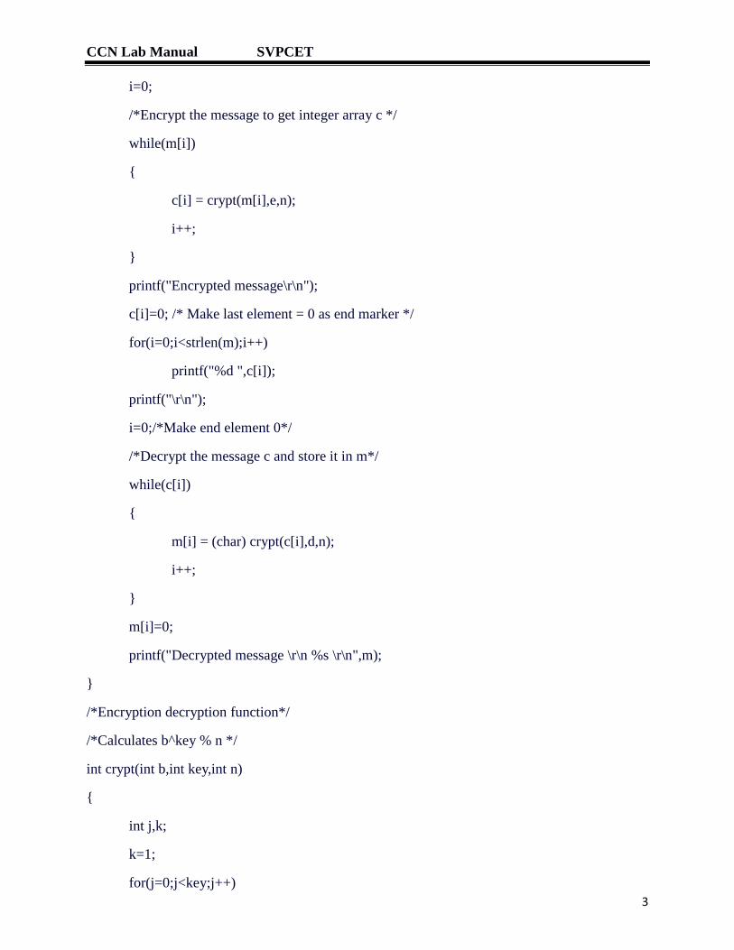
#include<stdio.h>
#include<string.h>
/* Key pair is obtained with p=17,q=23*/
/*Private key =3, public key = 235 */
int e=3,d=235,n=391;
char m[100];/*Plain text message*/
int c[100]; /*Cipher text message*/
int i;
int crypt(int b,int key,int n); /*Encrypt Decrypt function*/
int main()
{
printf("ENTER MESSAGE\r\n");
fflush(stdin);
scanf("%s",m);
CCN Lab Manual SVPCET
3
i=0;
/*Encrypt the message to get integer array c */
while(m[i])
{
c[i] = crypt(m[i],e,n);
i++;
}
printf("Encrypted message\r\n");
c[i]=0; /* Make last element = 0 as end marker */
for(i=0;i<strlen(m);i++)
printf("%d ",c[i]);
printf("\r\n");
i=0;/*Make end element 0*/
/*Decrypt the message c and store it in m*/
while(c[i])
{
m[i] = (char) crypt(c[i],d,n);
i++;
}
m[i]=0;
printf("Decrypted message \r\n %s \r\n",m);
}
/*Encryption decryption function*/
/*Calculates b^key % n */
int crypt(int b,int key,int n)
{
int j,k;
k=1;
for(j=0;j<key;j++)

CCN Lab Manual SVPCET
4
k=(k*b)%n;
return k;
}
Result:- Thus we have encrypted and decrypted a message using RSA algorithm.
Conclusion: We can use public key cryptography.
CCN Lab Manual SVPCET
5
Viva Question:
1 What are applications of RSA?
2 Out of RSA and DES, which one requires more computation?
3 What is public key cryptography?
4 Why we don't calculate me using power function?


![Gestión de incidentes - CCN-CERT · VIII JORNADAS STIC CCN-CERT Incidentes notificados [CCN-CERT#140127491] Detectado contacto DNS ciberataque BYC [CCN-CERT#140128142] Detectado](https://img.dokumen.tips/doc/110x75/5bb5751209d3f230088cd247/gestion-de-incidentes-ccn-cert-viii-jornadas-stic-ccn-cert-incidentes-notificados.jpg)