Embed Size (px)
Citation preview

1
ENGI 7704 Design of Steel Structures
Computer Analysis of Steel
Structures by S-Frame
2
S-Frame Capabilities
Automatic generation of trusses, multi-storey frames, arches, circles and spirals User friendly graphical interface International steel section and material database plus facilities to input tapered sections and custom sections using generic shape wizards or a simple graphical editor No practical limit on the size of the model Integrated Structural Steel Design (S-STEEL™) and Reinforced Concrete Design (S-CONCRETE™) Rigid and flexible diaphragm modeling Simple creation of panels (and holes) with automatic meshing and loading options Beam, truss, linear spring and inactive elements Buckling analysis Moving load analysis Staged construction Tension/compression only elements Many more advanced features
3
S-Frame Tutorial No.1
ANALYSIS & DESIGN OF STEEL TRUSS

4
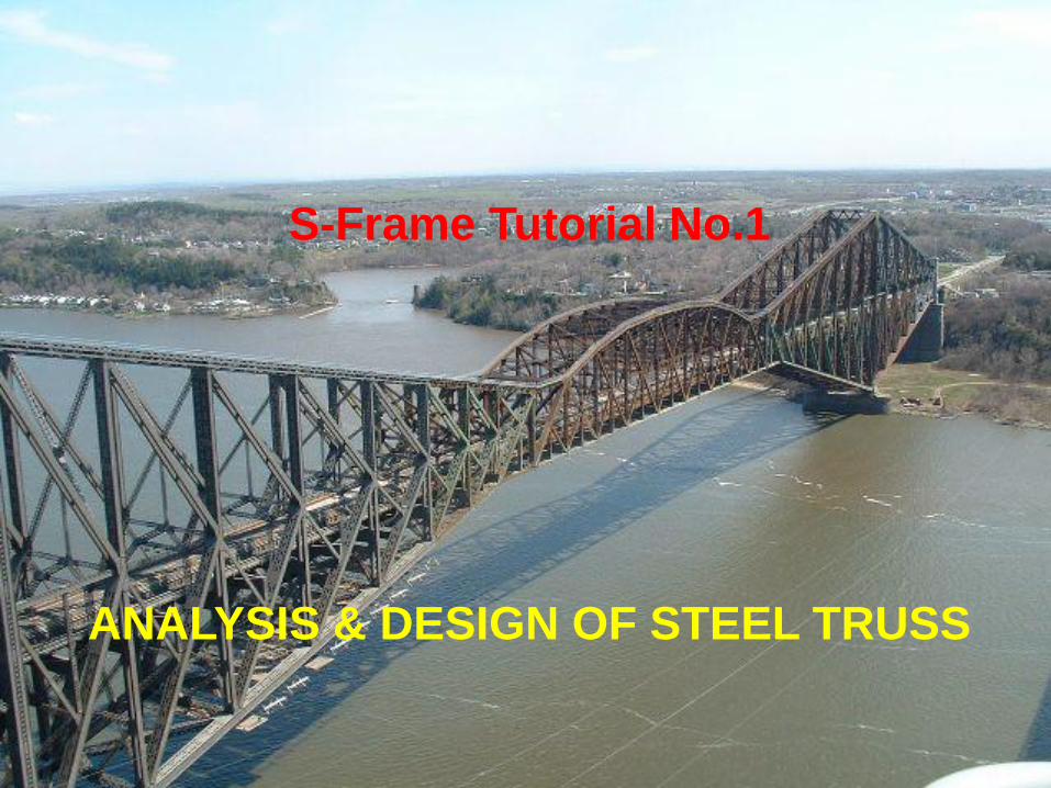
The figure above shows a steel truss from several trusses supposed to
cover a certain area. As shown, the truss has a cantilever part its span
equals 4.0m. The proposed truss depth is 3.0m.The loads as shown,
are concentrated at the truss joints. The values of its load case are
shown. The horizontal bars are L55x55x3 and the vertical and diagonal
bars are L45x45x3. Analyze this truss and investigate the if these
sections meet the design criteria.
TUTORIAL NO.1: STEEL TRUSS

5
Engineering Problems
Modeling
Geometry
Loading
Analyzing
Design

6
How to start S-Frame

7
Create New Model
Create a new 2D model

8
Setting up the model
9
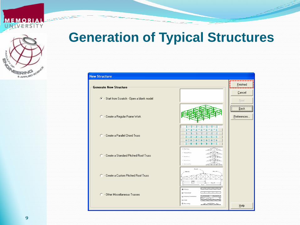
Generation of Typical Structures

10
S-Frame Interface

11
Defining the Joints
Right Click
Specify the joint
location
Specified number of joints can be automatically generated
at equal distance

12
Defining the Joints
Total of 4 joints
are generated
3 joints are added to joint 1 with horizontal spacing of 4.0 m
Joint 1

13
Defining the Joints
Total of 4 joints
are generated
3 joints are added to joint 5 with horizontal spacing of 4.0 m
Joint 5
To generate the upper
joints same procedure
should be followed.
First a joint at (0.0, 3.0)
is added and then 3
joints are copied with
horizontal distance of
4.0 m.

14
Zoom Structure Extents
To show all joints on the screen

15
The Generated Nodes
16
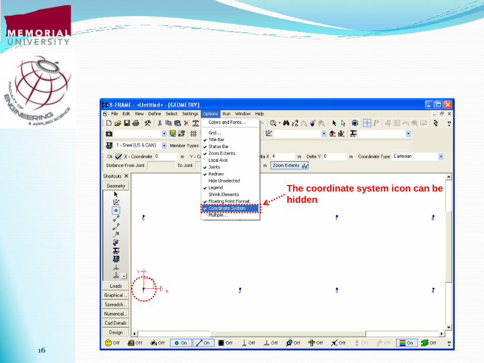
The coordinate system icon can be
hidden

17
Click here to enter member definition tool
Members are added using the joints that have
been already defined in the previous step
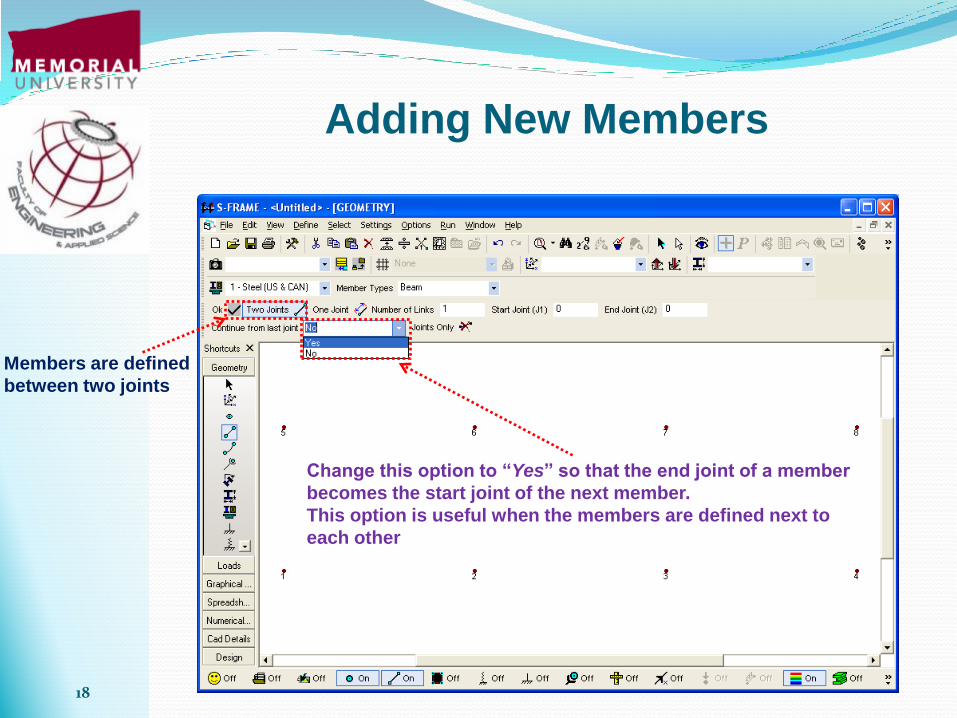
Adding New Members
18
Members are defined
between two joints
Change this option to “Yes” so that the end joint of a member
becomes the start joint of the next member.
This option is useful when the members are defined next to
each other
Adding New Members

19
Adding New Members
1: Click on first joint
2: Connect it to next joint 3: Because the “continue” option is selected
another member is automatically drawn and it
should be connected to next joint
4: When done, press ESC to cancel
defining new members
Complete the Model

20
Right click to
activate the tool Two node members can
be any of these element
types
These elements
can be shown by
different colors
Assigning member type

21
Assigning member type
Legend shows that blue members are “Beam”
elements.
They should be changed to “Truss” elements.
Select the “Truss” member type

22
Assigning member type
1. Member type is set to “Truss”
2. Using the mouse, all the structure is selected
by holding mouse left button and drawing a box
around the structure.
The members would then become red.
23
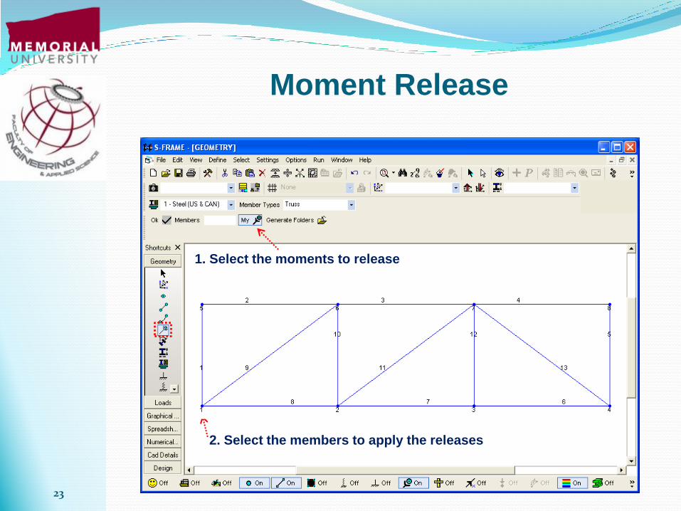
Moment Release
1. Select the moments to release
2. Select the members to apply the releases

24
Enter section
properties
Section Color
Defining Section Properties for the members Member Release
Click to access standard
sections in the database

25
Importing Standard Sections
Section
categories
Section properties
Section name

26
Importing Standard Sections
Click to select
“Angles”
Click to find
desired
sections from
drop down
menu
Select the required
section
27
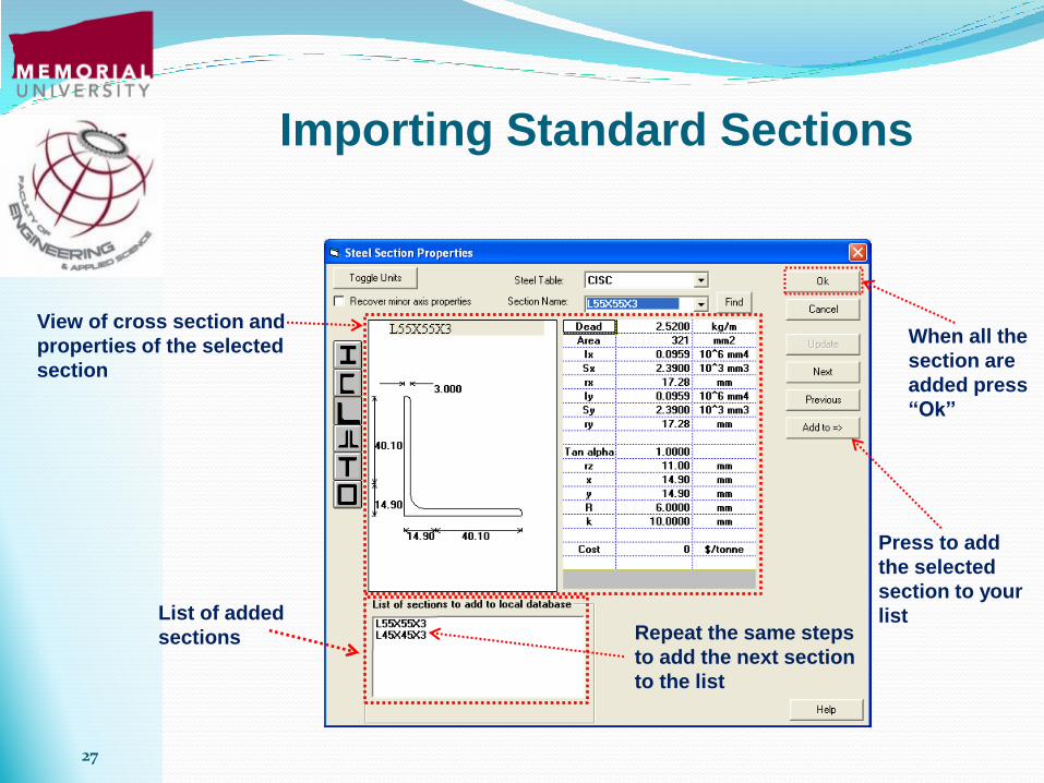
Importing Standard Sections
View of cross section and
properties of the selected
section
Press to add
the selected
section to your
list List of added
sections Repeat the same steps
to add the next section
to the list
When all the
section are
added press
“Ok”

28
Importing Standard Sections
Assign “Blue” to first
section and “Red” to the
second one

29
Assigning Section to the Members
Legend shows all the sections are automatically
assigned the first section in the list, i.e. L55x55x3
Select second section L45x45x3
Using “Shift” key draw an intersecting line to select the vertical
and diagonal members that should be assigned L45x45x3
The vertical and
diagonal members
become red to
show they are
assigned L45x45x3
section
30
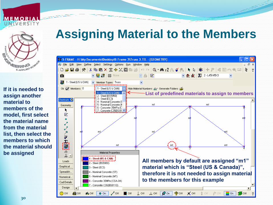
Assigning Material to the Members
All members by default are assigned “m1”
material which is “Steel (US & Canada)”,
therefore it is not needed to assign material
to the members for this example
List of predefined materials to assign to members If it is needed to
assign another
material to
members of the
model, first select
the material name
from the material
list, then select the
members to which
the material should
be assigned

31
Add New Material
2. Choose a name for the new material
3. Enter material properties
4. Press to
add the
material
1. Right Click
to open the
tool
32
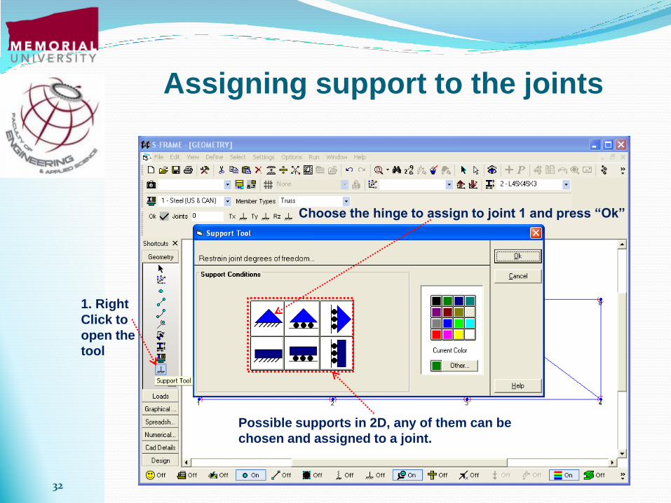
1. Right
Click to
open the
tool
Choose the hinge to assign to joint 1 and press “Ok”
Possible supports in 2D, any of them can be
chosen and assigned to a joint.
Assigning support to the joints

33
Assigning support to the joints
Hinge: movement is fixed at x and y direction
Click on joint 1 to be assigned the hinge
Activate the corresponding support (movement in y direction) to
represent the roller and then click on joint 3 to which a roller
should be assigned

34
The geometry of the
model is now complete.
In next step the model
loading should be
defined.
Remember to save your work from time to
time

35
Click to add new
Load Case
Define New Load Case

36
Choose a Load Case name,
first case is “Self-Weight”
For Self-Weight load
gravitational factor at y
direction is set to -1.0
Press “Ok” to
add the Load
Case
Define New Load Case

37
Define New Load Case
Next Case is “Dead Load”
Gravitational
factor should be
set back to 0
Press “Ok” to
add the “DL”
case to the load
cases
Repeat this step to add
other load cases:
Live Load: LL
Wind Load: WL

38
Defining New Load Combination
Click to add new Load Combination
39
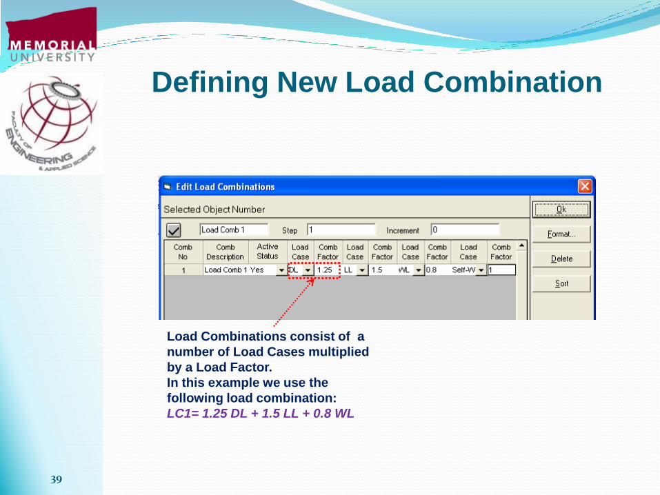
Defining New Load Combination
Load Combinations consist of a
number of Load Cases multiplied
by a Load Factor.
In this example we use the
following load combination:
LC1= 1.25 DL + 1.5 LL + 0.8 WL

40
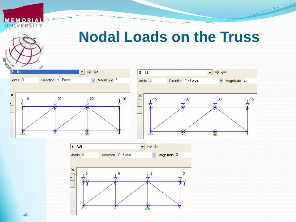
Assign Nodal Load
1. Select Load
Case from the
case list menu 2. Select the load direction 3. Enter the load magnitude
4. Click on the nodes to which the load is applied
41
Nodal Loads on the Truss

42
When the model is ready, that is the
geometry and loading is complete, it is
possible to run the analysis to obtain the
model deformations, member forces and
stresses
Analyze the Model

43
Analyze for both Load
Cases and Load
Combinations
Select the analysis type,
choose “Linear Static”
for this example
Press
“Ok” to
run the
analysis
Analyze the Model

44
Analysis Report
45
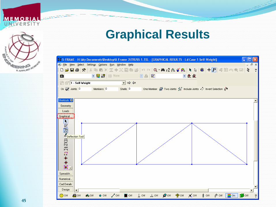
Graphical Results

46
The analysis results can be viewed under any load case
The loads of “Wind Load” case is shown
Graphical Results

47
The results of “Load Combinations”
can also be viewed
Graphical Results

48
The deformed structure under the load combination
Graphical Results

49
Graphical Results

50
Graphical Results
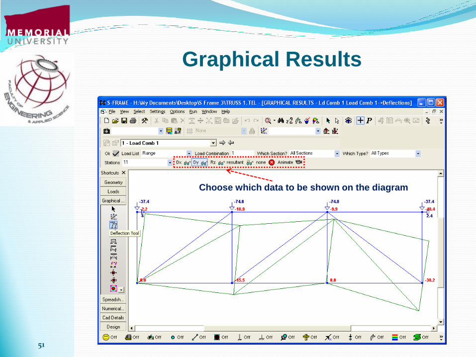
Check this box to show the numerical results on the diagrams
51
Choose which data to be shown on the diagram
Graphical Results

52
Graphical Results

53
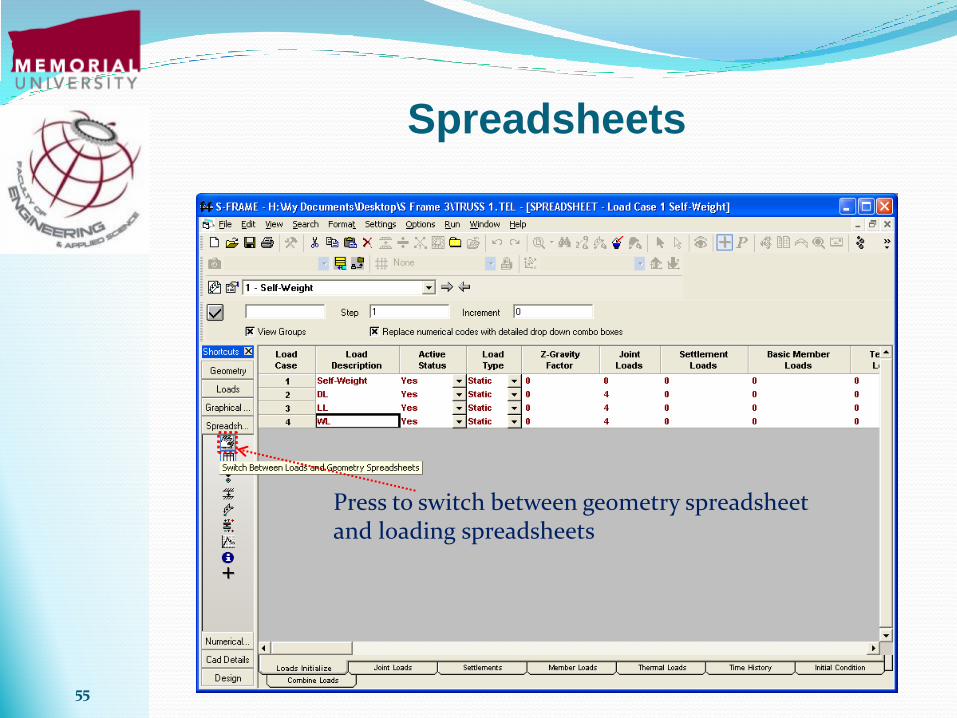
Spreadsheets
Spreadsheets provide full access to the model geometry and loading. Any data can be edited in spreadsheets.

54
Spreadsheets
55
Spreadsheets
Press to switch between geometry spreadsheet and loading spreadsheets
56
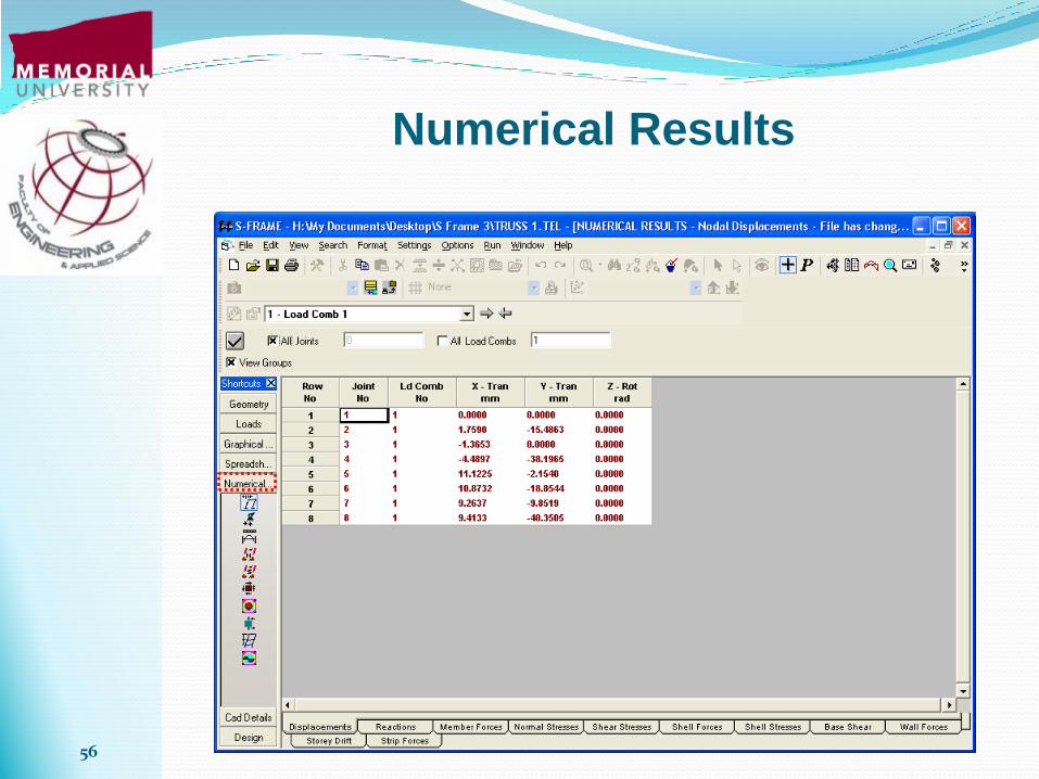
Numerical Results

57
Numerical Results
Results are shown
at different
locations of a
member.

58
Numerical Results

59
Numerical Results

60
Design

61
Design Module: S-Steel

62
Always remember to
select all the members

63
Code Check
The “Code Check” window
examines if the current sections
of the model meet the design
code provision.

64
Utilizations Ratios

65
Design Report

66
67
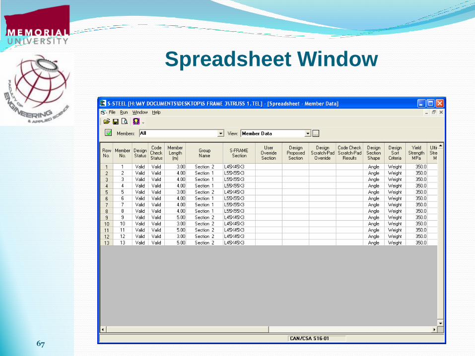
Spreadsheet Window

68
Section that can be
used in the design
Design
69
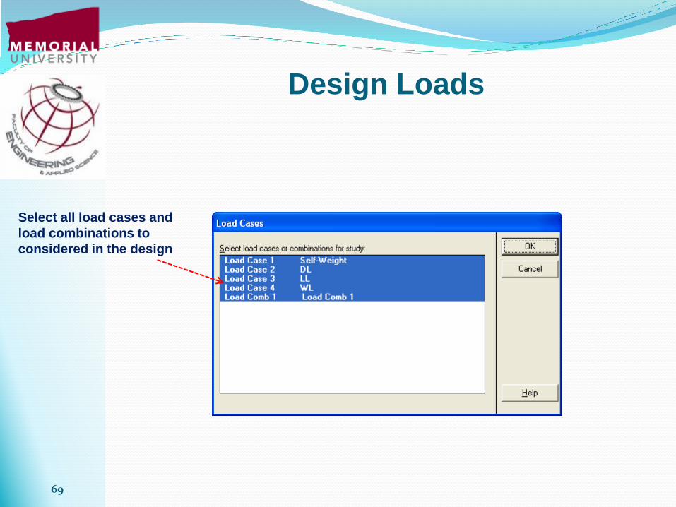
Design Loads
Select all load cases and
load combinations to
considered in the design

70
Reanalyze the model after the
“Design” as new sections are
assigned to the members.

71
All the sections pass the “Code
Check” after the design.