Embed Size (px)
Citation preview
COMPUTER AIDED COORDINATION OF DIRECTIONAL PROTECTION RELAYS: TOPOLOGICAL ANALYSIS
B D Stedall, Y Chen, R K Aggarwal, A T Johns and P J Moore School of Electronic and Electrical Engineering, University of Bath,
Bath, United Kingdom
Keywords:- Protection, Protection Coordination, Graph Theory.
Abstract:- Systematic coordination of directional protection . relays within power system networks is promoted by the utilisation of graph theory. This paper will discuss and extend the concepts associated with the enumeration of all simple loops, a necessary prerequisite in the coordination of directional protection relays. In particular, it will overcome problems associated with some present published algorithms in the enumeration of all simple loops in highly complex power system networks. An algorithm is presented and explained by use of worked examples.
1. INTRODUCTION
Historically, engineers have systematically calculated the setting of protection relays based on topology, assumed operating conditions and experience using traditional methods. This task is time consuming and tedious, resulting in the relays being set to reflect the worst case fault scenario. Under severe topological and operating condition alterations, this results in protection system performance degradation.
There has been considerable interest in software tools for protection coordination automation. Off line protection coordination applications have enabled fast and efficient protection system design. More recently the concept of adaptive protection has arisen, whereby the protection relays in the system adjust themselves, in sympathy with changing power system conditions, thus optimising the protection system performance. Realisation of such a system requires more efficient computer aided protection coordination algorithms. Research into computer aided protection coordination has included solutions utilising expert systems [1], functional dependency theory [2], optimisation theory [3] and graph theory [4,5,6,7,8,9], although only the latter is within the scope of this paper. Prior to performing relay coordination it is necessary to analy:re the topology of the network and enumerate all simple loops.
This paper seeks to review and extend the work started by Damborg et al [4,5,6,7,8] and continued by Rao et al [9] for the enumeration of all simple loops, a necessary step in the determination of the break point
1187
set and relative sequence matrix for relay coordination.
2. TOPOLOGICAL ANALYSIS
2.1 Definitions
linear graph:- a collection of edges (transmission lines/ transformers) and vertices (busbars).
loop:- a closed sequence of edges within the graph forming a path, whose starting and ending vertex are the same.
subgraph:- a subset of edges of a linear graph.
tree:- a connected subgraph of a graph containing all the vertices and no loops.
fundamental loop:- a loop formed when an edge not in · a tree of the graph (chord) is added to the tree.
simple loop:- a loop in which the degree of all vertices are two.
2.2 Structural Analysis of the Power System Network
Coordination of directional relays, for a given fault condition, requires the comparison of the performance of the primary relay to that of all relays which are backup to that relay. This requires the identification of all primary/backup pairs within the network.
In addition, the coordination requires the logical determination of a sequence by which to set the protection relays. Consider the coordination of the prqtection on radial feeders. The common approach is to start at the load and work towards the source. In networks containing loops, this approach is not applicable until a 'break' is introduced into the loop. The broken loop is coordinated as for a radial feeder, starting at the relay closest to the break, the break point relay, and working around the loop to the most upstream relay. An additional constraint now applies in that the most upstream relay must coordinate with the break point relay. Should this not occur, it is necessary to alter the break point relay setting and repeat the process. In multi-loop networks, to eQsure protection relay coordination, all loops must be broken at least once at the
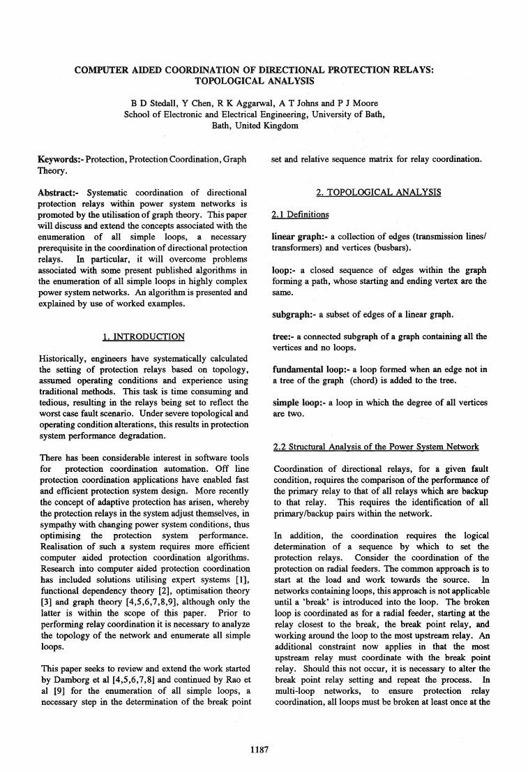
same time, the set of edges removed to break all simple loops forming a break point set (BPS) of relays. The BPS is not unique. It should be chosen such that it is minimal to avoid excessive computation, especially where loops share the same branches. The remainder of the protection relays are systematically set such that the setting value of the current relay under consideration is only dependent on those appearing before , it m the relay sequence and is given in the relative sequence matrix (RSM). To organise the relay coordination, the topology of the network must be analysed to give the primary/backup pairs, a minimal break point set and an efficient sequence by which to set the remaining relays. To enable the determination of the BPS the identification of and analysis of all simple loops, by directed, linear graphs are used. 'Qie electrical power transmission network of · Fig.1 is represented by the directed linear graph of Fig.2. The interconnection of components within the system is defined by the incident matrix, A, relating busbars (vertices) to transmission lines (edges). The corresponding directed incident matrix for this network, as shown below, describes the structure of the network and it is from this that the simple loops are enumerated to enable the analysis of the coordination requirements of directional protection relays.
A=ABCDE 1 1 0 0 0 0 2 -1 1 1 1 0 3 0 0 0 -1 1 4 0 0 0 0 0 s o -1 o ·o o
F 0 0 1 0 0
G HI J 0 0 0 0 0 0 0 0 1 0 0 0 -1 1 0 0 0 0 -1 0
k L MN 0 0 0 0 0 0 0 0 0 0 0 0 0 0 0 0 0 0 0 0
6 0 0 -1 0 -1 0 0 0 1 1 1 -1 0 0 7 0 0 0 0 0 -1 0 -1 0 0 0 1 -1 0 8 0 0 0 0 0 0 0 0 0 -1 0 0 0 1 9 0 0 0 0 0 0 0 0 0 0 -1 0 1 -1
3
Fig.1 Electrical Power Transmission Network
1188
Fig.2 Linear Graph of Network ·
9
Fig.3 Trees of Linear Graph
2.3 Review of Methodologies for the Enumeration of Simple Loops
The relationships between edges and vertices have already been specified in the incident matrix, A. Directional protection may be represented by the directed edges of the linear graph. To represent the protection in both directions, it is necessary to expand the incident matrix. For the above network graph, where A has e edges and v vertices, the corresponding expanded incident matrix, A' representing the protection has (2 x e) edges and v vertices. The components of the A' matrix from column 1 to column e are the same as those of the A matrix and from column (e+ 1) to column (2 x e) correspond to A scalar multiplied by -1.
[A ~=[[A]: -lx[A]]
As it is only within the scope of this paper to enumerate all simple loops, and to reduce the matrix size for ease of

explanation, it will be assumed that A is equal to A'. To determine the BPS and corresponding RSM it is necessary to enumerate all simple loops within the network. · The simple loops of a network may be derived from a combination of the fundamental loops which in tum may be formed by each chord and its associated directed tree of the network. By searching the A matrix, an arbitrary directed tree, as shown in fig.3, is derived comprising branches A,B,C,D,F,G,J and K. From this the directed fundamental loops may be determined. For a graph there exists t ( = e-v + 1) fundamental loops, defined in B, where e is the number of edges and v the number of vertices in the graph respectively.
B= AB CD E F G HI J KL MN L1 0 0 -1 1 1 0 0 0 0 0 0 0 0 0 L2 0 0 -1 1 0 1 0 0 0 0 0 1 0 0 L3 0 -1 1 0 0 0 0 0 1 0 0 0 0 0 IA 0 0 0 0 0 . -1 1 1 0 0 0 0 0 0 LS 0 0 1 -1 0 -1 0 0 0 0 1 0 1 0 L6 0 0 0 0 0 0 0 0 0 1 -1 0 0 1
It has been stated that the simple loops of a linear graph are a combination of some of the fundamental loops, the maximum number of simple loops being 21-1. The possible combinations may be represented in binary form:
L6 LS
0 0 0 0 0 0
1 1 1
• • • 1 1 1
IA L3
0 0 0 0 0 0
1 1 1
1 1 1
L2 L1
0 1 1 0 1 1
0 1 1
1 0 1
To determine whether the linear combinations of these circuits result in a loop or not for the example graph, with reference to fig.2, consider the combination of fundamental loops L1, L2 and IA comprising of edge sets {C,D,E}, {C,D,F,L} and {F,G,H} respectively. Previous work [9], states the necessary following condition for the determination of simple loops.
Condition 1: a simple loop is derived from a linear combination of fundamental loops, provided the fundamental loops to be combined have at least one common edge, by deleting from the union of the edge sets those members present in even numbers.
This would yield the simple loop comprising of edges {E,G,H,L}. In practice the linear combinations of
1189
fundamental loops would be placed in a matrix, say F, and in the above example L1, L2 and IA would be represented as:
F~ A B c D E F G HI J KL MN o·o -1 1 1· 0 0 0 0 0 0 0 0 0 0 0 -1 1 0 1 0 0 0 0 0 1 0 0 0 0 0 0 0 -1 1 1 0 0 0 0 0 0
From Condition 1 it is firstly necessary to determine which of these columns have even numbers of non-zero entries, and secondly select one of these columns, k, such that the entry in the first row of that column is non-zero. The rows with corresponding non-zero elements in column k are logically exclusive ored together. In the above example, columns C, D and F have even numbers of non-z.ero elements, although only columns C and D have non-zero elements in the first row. Arbitrarily choosing column D, with non-zero elements in the first two rows, enables the combination of Ll and L2 to give:
F= AB CDEF GHI J KLMN 0 0 0 0 1 1 0 0 0 0 0 1 0 0 0 0 0 0 0 -1 1 1 0 0 0 0 0 0
Applying condition 1 again, reduces F to:
F= AB CDEF GHI J KLMN 0 0 0 0 1 0 1 1 0 0 0 1 0 0
Thus the edge set {E,G,H,L} constitute a simple loop, and this may be confirmed by viewing the linear graph, fig.2.
Conversely, if the fundamental loops L1, L2 and L3 are to be combined the corresponding F matrix is:
F= AB CDE F GHI J KLMN 0 0 -1 1 1 0 0 0 0 0 0 0 0 0 0 0 -1 1 0 1 0 0 0 0 0 1 0 0 0 -1 1 0 0 0 0 0 1 0 0 0 0 0
Loops L1 and L2 are combined as shown below although further reduction is not possible as there are no remaining columns with even numbers of non-zero entries and hence this combination of fundamental loops does not result in a simple loop.
F= AB CDEF GHI J KLMN 0 0 0 0 1 1 0 0 0 0 0 1 0 0 0 -1 1 0 0 0 0 0 1 0 0 0 0 0
The conditions as stated are necessary but not sufficient. The necessity for enhancements to these conditions are outlined and illustrated in the following section.
2.4 Enhancements to the Conditions for the Correct Enumeration of all Simple Loops within the Network
The previous ~tion illustrated the enumeration of simple loops by the determination of the combination of fundamental loops in accordance with Condition 1. However, by satisfying Condition 1, it is possible for a given combination of fundamental loops to reduce the F matrix to one row, implying that the remaining row is a simple loop, when in fact it is not. This occurs when the degree of one or more nodes in a combined loop are greater than two, and is described below. Assume that four fundamental loops are to be combined with edge sets: ·
Ll = (a1,ai, ... ,8j, ••• ,11ic, ••• ,8n1) L2 = (b1,1Ji, ... ,bi, ... ,ak, ... ,bn2) L3. = (c1,ei, ... ,8j, .. ;,11ic, ••• ,cn3)
IA= (d1,d2····A·····8ic·····d,..i)
where 8i = an edge contained in two of the fundamental loops in this combination.
Ilic = an edge contained in four of the fundamental loops in this combination with vertices k1 and k2.
In addition, it is assumed that all edges, excluding 8i and Ilic• are not contained in more than one of the fundamental loop edge sets. Utilising Condition l, the coiumns containing 8i and Ilic are removed as they occur an even number of times, whilst all other edges remain. The number of rows in F has been reduced from four to one. On examination, it is found that the calculated circuit is not a simple loop, as the degree of one or both of the vertices k1 and k2 of edge ak is greater than two. In this instance, the deletion of edge a.c. appearing an even number of times in the F matrix, has resulted in the degree of edge k1 and/or k2 becoming 4. The previously stated definitions, state that the degree of any node within a simple loop is 2. Thus the combination of fundamental loops, has not resulted in a simple loop.
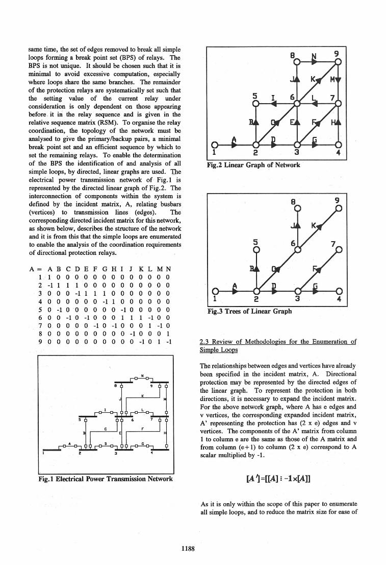
This is illustrated by considering the ·Iinear combination of fundamental loops L1, L2, L3 and L5 in the example power transmission network resulting in the F matrix below. The network is highly interconnected, on busbar 6, to illustrate problems in topological analysis that previous authors have not addressed due to them not being apparent in their simple examples.
F= A B CD E F G HI J KLMN 0 0 -1 1 1 0 0 0 0 0 0 0 0 0 0 0 -1 1 0 1 0 0 0 0 0 1 0 0 0 -1 1 0 0 0 0 0 1 0 0 0 0 0 0 0 1 -1 0 -1 0 0 0 0 1 0 1 0
By reducing this, with respect · to Condition 1, it is possible to obtain:
F= ABCDEFGHI J KLMN 0 -1 0 1 1 0 0 0 1 0 -1 -1 -1 0
The calculated simple loop formed by this combination of fundamental loops, in accordance with Condition 1, is shown in fig,4. The degree of vertex 6 is 4. Examination shows that edge C is involved in four fundamental loops, such that the resulting calculated simple loop is not a simple loop in accordance . with the previously stated definitions. The determination of the BPS and corresponding RSM is dependent on the correct enumeration of simple loops to ensure correct protection relay coordination. It is therefore necessary to add a
. further condition to check that the . degree of all nodes in a combined loop is not greater than two.
1190
Condition 2: The degree of a node or vertex m a combined loop must not be greater than two.
Should both Condition 1 and Condition 2 be satisfied, both necessary and sufficient conditions for the correct calculation of all simple loops are met. Utilising the enumerated simple loops, it is now possible to determine the correct break point set of relays and relative sequence matrix, enabling correct coordination of directional protection relays.
0 1 2 3
9
· o 4
Fig.4 Calculated Simple Loop for the combination of fundamental loops Ll, L2, L3 and LS in accordance with Condition 1.
3. THE COMPUTER ALGORITHM
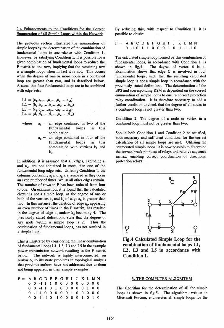
The algorithm for the determination of all the simple loops is shown in fig.5. The algorithm, written in Microsoft Fortran, enumerates all simple loops for the

Deter-Ml• dr.c:Wd tnt• llnd llll 'undcl.Plirn'tlll loo s
I • l
PlAC9 'ttw Ith col'lbino. tlon oF 511'1pl9 loops Into l'lll'trbc r ,
rind 'tt. COlUl'lftll 11'1 r With .v•n llUl'IHrS a, nan-zer"O .i ... nts llnd star• In lll"l"Cl S
le • f'lrri .i-nt 11'1 s
row = 2
rc1.0 • ra.o XDR rc1c.1>
le • rwrl ltl•Mnt In S
Tt... Ith col'lllllnlltlon lllo9s nat f'oNI ll!ll l•lo
Fig.5 Flow Diagram for Enumeration of Simple Loops
1191

above network in 1.1 seconds, on an IBM 80486-33 personal computer. The corresponding run time for the network in Rao et al's [8] paper is 0.55 seconds.
4. CONCLUSIONS
Utilisation of graph theory for the enumeration of simple loops, a necessary prerequisite for the coordination of directional protection relays has been discussed. Conditions stated by previous authors, although necessary, have been extended to make them sufficient for the correct determination of simple loops. An algorithm has been presented, and explained by the use of worked examples. This lays a strong foundation, in the computer aided protection coordination algorithm, for the determination of the break point set and relative sequence matrix, and hence the coordination of directional protection relays.
5.ACKNOWLEDGEMENTS
The'authors would like to thank the University of Bath and the National Grid pie for provision of facilities and kind permission to publish this work.
6. REFERENCES
1. A.L. Lai, "Development of an Expert System for Power System Protection Coordination", Proceedings of the Fourth International Conference on Developments in Power System Protection, IEE Conference Publication No. 302, pp. 310 - 314, April 1989.
2. L. Jenkins, H.P. Khincha, S. Shivakumar and P.K. Dash, "An Application of Functional Dependencies to the Topological Analysis of Protection Schemes", IEEE Transactions on Power Delivery, Vol. 7, No. 1, pp. 77 - 83, January 1992.
1192
3. A.J. Urdaneta and L.G. Perez Jimezez, "Optimal Coordination of Directional Overcurrent Relays in Interconnected Power Systems", IEEE Transactions on Power Delivery, Vol. 3, No. 3, pp. 903 - 911, July 1988.
4. M.J. Damborg, R. Ramaswani, J.M. Postforooshand S.S. Venkata, "Computer Aided Protection System Design - Part 1: Algorithms", IEEE Transactions on PAS, Vol. 103, No. 1, pp. 51 - 59, Jan. 1984.
5. R. Ramaswani, S.S. Venkata, M.J. Damborg and J.M. Postforoosh, "Computer Aided . Protection System Design - Part II: Implementation and Results", IEEE Transactions on PAS, Vol. 103, No. 1, pp. 60 -65, Jan. 1984, .
6. R. Ramaswani, S.S. Venkata, M.J. Damborg, A.K. Jampala and J.M. Postforoosh, "Enhanced Algorithms for Transmission Protective Relay Coordination", IEEE Transactions on Power Delivery, Vol. PWRD-1, No. 1, pp. 280 - 287, January 1986.
7. S.S. Venkata, A.K. Jampala, R. Ramaswani, M.J. Damborg. and J.M. Postforoosh, "CAE Software for Transmission Protection System: PUGET Power Experience", IEEE Transaction on Power Delivery, Vol. PWRD:-2, No. 3, pp. 691 - 698, July 1987.
8. M.J. Damborg, R. Ramaswani, A.K. Jampala and S.S. Venkata, "Application of Relationaf Database to Computer Aided Engineering of Transmission Protection Systems", IEEE Transactions on Power Systems, Vol. PWRS-1, No. 2, pp. 187 - 93, May 1986. '
9. V.V Bapeswara Rao and K. Sankara Rao, "Computer Aided Coordination of Directional Relays: Determination of Break Points", IEEE Transactions on .Power Delivery, Vol. 3, No. 2, pp. 545 - 548, April 1988.