Embed Size (px)
Citation preview
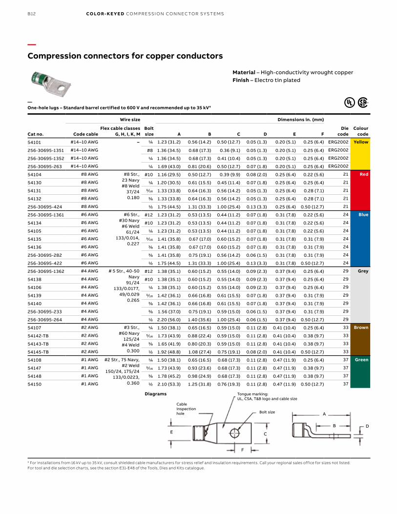
B12 CO LO R- K E Y E D CO M PR E SSI O N CO N N EC TO R S Y S TEMS
—Compression connectors for copper conductors
Material – High-conductivity wrought copperFinish – Electro tin plated
Cat no.
Wire size
Bolt size
Dimensions in. (mm)
Die code
Colour codeCode cable
Flex cable classes G, H, I, K, M A B C D E F
54101 #14–10 AWG – 1/4 1.23 (31.2) 0.56 (14.2) 0.50 (12.7) 0.05 (1.3) 0.20 (5.1) 0.25 (6.4) ERG2002 Yellow
256-30695-1351 #14–10 AWG #8 1.36 (34.5) 0.68 (17.3) 0.36 (9.1) 0.05 (1.3) 0.20 (5.1) 0.25 (6.4) ERG2002
256-30695-1352 #14–10 AWG 1/4 1.36 (34.5) 0.68 (17.3) 0.41 (10.4) 0.05 (1.3) 0.20 (5.1) 0.25 (6.4) ERG2002
256-30695-263 #14–10 AWG 1/4 1.69 (43.0) 0.81 (20.6) 0.50 (12.7) 0.07 (1.8) 0.20 (5.1) 0.25 (6.4) ERG2002
54104 #8 AWG #8 Str., 23 Navy#8 Weld
37/240.180
#10 1.16 (29.5) 0.50 (12.7) 0.39 (9.9) 0.08 (2.0) 0.25 (6.4) 0.22 (5.6) 21 Red
54130 #8 AWG 1/4 1.20 (30.5) 0.61 (15.5) 0.45 (11.4) 0.07 (1.8) 0.25 (6.4) 0.25 (6.4) 21
54131 #8 AWG 5⁄16 1.33 (33.8) 0.64 (16.3) 0.56 (14.2) 0.05 (1.3) 0.25 (6.4) 0.28 (7.1) 21
54132 #8 AWG 3/8 1.33 (33.8) 0.64 (16.3) 0.56 (14.2) 0.05 (1.3) 0.25 (6.4) 0.28 (7.1) 21
256-30695-424 #8 AWG 1/2 1.75 (44.5) 1.31 (33.3) 1.00 (25.4) 0.13 (3.3) 0.25 (6.4) 0.50 (12.7) 21
256-30695-1361 #6 AWG #6 Str., #30 Navy
#6 Weld61/24
133/0.014, 0.227
#12 1.23 (31.2) 0.53 (13.5) 0.44 (11.2) 0.07 (1.8) 0.31 (7.8) 0.22 (5.6) 24 Blue
54134 #6 AWG #10 1.23 (31.2) 0.53 (13.5) 0.44 (11.2) 0.07 (1.8) 0.31 (7.8) 0.22 (5.6) 24
54105 #6 AWG 1/4 1.23 (31.2) 0.53 (13.5) 0.44 (11.2) 0.07 (1.8) 0.31 (7.8) 0.22 (5.6) 24
54135 #6 AWG 5⁄16 1.41 (35.8) 0.67 (17.0) 0.60 (15.2) 0.07 (1.8) 0.31 (7.8) 0.31 (7.9) 24
54136 #6 AWG 3/8 1.41 (35.8) 0.67 (17.0) 0.60 (15.2) 0.07 (1.8) 0.31 (7.8) 0.31 (7.9) 24
256-30695-282 #6 AWG 3/8 1.41 (35.8) 0.75 (19.1) 0.56 (14.2) 0.06 (1.5) 0.31 (7.8) 0.31 (7.9) 24
256-30695-422 #6 AWG 1/2 1.75 (44.5) 1.31 (33.3) 1.00 (25.4) 0.13 (3.3) 0.31 (7.8) 0.50 (12.7) 24
256-30695-1362 #4 AWG # 5 Str., 40-50 Navy
91/24133/0.0177,
49/0.0290.265
#12 1.38 (35.1) 0.60 (15.2) 0.55 (14.0) 0.09 (2.3) 0.37 (9.4) 0.25 (6.4) 29 Grey
54138 #4 AWG #10 1.38 (35.1) 0.60 (15.2) 0.55 (14.0) 0.09 (2.3) 0.37 (9.4) 0.25 (6.4) 29
54106 #4 AWG 1/4 1.38 (35.1) 0.60 (15.2) 0.55 (14.0) 0.09 (2.3) 0.37 (9.4) 0.25 (6.4) 29
54139 #4 AWG 5⁄16 1.42 (36.1) 0.66 (16.8) 0.61 (15.5) 0.07 (1.8) 0.37 (9.4) 0.31 (7.9) 29
54140 #4 AWG 3/8 1.42 (36.1) 0.66 (16.8) 0.61 (15.5) 0.07 (1.8) 0.37 (9.4) 0.31 (7.9) 29
256-30695-233 #4 AWG 3/8 1.56 (37.0) 0.75 (19.1) 0.59 (15.0) 0.06 (1.5) 0.37 (9.4) 0.31 (7.9) 29
256-30695-264 #4 AWG 1/2 2.20 (56.0) 1.40 (35.6) 1.00 (25.4) 0.06 (1.5) 0.37 (9.4) 0.50 (12.7) 29
54107 #2 AWG #3 Str., #60 Navy
125/24#4 Weld
0.300
1/4 1.50 (38.1) 0.65 (16.5) 0.59 (15.0) 0.11 (2.8) 0.41 (10.4) 0.25 (6.4) 33 Brown
54142-TB #2 AWG 5⁄16 1.73 (43.9) 0.88 (22.4) 0.59 (15.0) 0.11 (2.8) 0.41 (10.4) 0.38 (9.7) 33
54143-TB #2 AWG 3/8 1.65 (41.9) 0.80 (20.3) 0.59 (15.0) 0.11 (2.8) 0.41 (10.4) 0.38 (9.7) 33
54145-TB #2 AWG 1/2 1.92 (48.8) 1.08 (27.4) 0.75 (19.1) 0.08 (2.0) 0.41 (10.4) 0.50 (12.7) 33
54108 #1 AWG #2 Str., 75 Navy, #2 Weld
150/24, 175/24133/0.0223,
0.360
1/4 1.50 (38.1) 0.65 (16.5) 0.68 (17.3) 0.11 (2.8) 0.47 (11.9) 0.25 (6.4) 37 Green
54147 #1 AWG 5⁄16 1.73 (43.9) 0.93 (23.6) 0.68 (17.3) 0.11 (2.8) 0.47 (11.9) 0.38 (9.7) 37
54148 #1 AWG 3/8 1.78 (45.2) 0.98 (24.9) 0.68 (17.3) 0.11 (2.8) 0.47 (11.9) 0.38 (9.7) 37
54150 #1 AWG 1/2 2.10 (53.3) 1.25 (31.8) 0.76 (19.3) 0.11 (2.8) 0.47 (11.9) 0.50 (12.7) 37
¥ For installations from 16 kV up to 35 kV, consult shielded cable manufacturers for stress relief and insulation requirements. Call your regional sales office for sizes not listed.For tool and die selection charts, see the section E31-E48 of the Tools, Dies and Kits catalogue.
Diagrams
—One-hole lugs – Standard barrel certified to 600 V and recommended up to 35 kV¥
E C
F
DB
A
Cableinspection hole Bolt size
Tongue marking: UL, CSA, T&B logo and cable size
B13
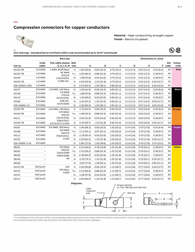
—Compression connectors for copper conductors
Cat no.
Wire size
Bolt size
Dimensions in. (mm)
Die code
Colour code
Code cable
Flex cable classes G, H, I, K, M A B C D E F
54152-TB 1/0 AWG 1 AWG, #100 Navy#1 Weld225/24
133/0.0254, 0.389 min.
1/4 1.60 (40.6) 0.65 (16.5) 0.75 (19.1) 0.13 (3.3) 0.52 (13.2) 0.25 (6.4) 42 Pink
54153-TB 1/0 AWG 5⁄16 1.83 (46.5) 0.88 (22.4) 0.75 (19.1) 0.13 (3.3) 0.52 (13.2) 0.38 (9.7) 42
54109 1/0 AWG 3/8 1.88 (47.8) 0.93 (23.6) 0.75 (19.1) 0.13 (3.3) 0.52 (13.2) 0.38 (9.7) 42
54155-TB 1/0 AWG 1/2 2.20 (55.9) 1.25 (31.8) 0.75 (19.1) 0.13 (3.3) 0.52 (13.2) 0.50 (12.7) 42
256-30695-1383 1/0 AWG 5/8 2.54 (64.5) 1.50 (38.1) 0.88 (22.4) 0.13 (3.3) 0.52 (13.2) 0.63 (16.0) 42
54157 2/0 AWG 1/0 AWG, 125 Navy1/0 Weld
275/24427/0.0155,
438 min.133/0.0282
1/4 1.65 (41.9) 0.65 (16.5) 0.83 (21.1) 0.13 (3.3) 0.57 (14.5) 0.25 (6.4) 45 Black
54158 2/0 AWG 5⁄16 1.88 (47.8) 0.88 (22.4) 0.83 (21.1) 0.13 (3.3) 0.57 (14.5) 0.38 (9.7) 45
54110 2/0 AWG 3/8 1.93 (49.0) 0.93 (23.6) 0.83 (21.1) 0.13 (3.3) 0.57 (14.5) 0.38 (9.7) 45
54160 2/0 AWG 1/2 2.25 (57.2) 1.25 (31.6) 0.83 (21.1) 0.13 (3.3) 0.57 (14.5) 0.50 (12.7) 45
256-30695-131 2/0 AWG 5/8 2.56 (65.0) 1.50 (38.1) 0.83 (21.1) 0.13 (3.3) 0.57 (14.5) 0.63 (16.0) 45
54162-TB 3/0 AWG 2/0 AWG, 150 Navy2/0 Weld,
325/24133/0.0316, 259/0.0227
427/0.0177, 0.500
1/4 1.75 (44.5) 0.65 (16.5) 0.92 (23.4) 0.13 (3.3) 0.63 (16.0) 0.25 (6.4) 50 Orange
54163-TB 3/0 AWG 5⁄16 1.98 (50.3) 0.88 (22.4) 0.92 (23.4) 0.13 (3.3) 0.63 (16.0) 0.38 (9.7) 50
54111 3/0 AWG 3/8 2.03 (51.6) 0.93 (23.6) 0.92 (23.4) 0.13 (3.3) 0.63 (16.0) 0.38 (9.7) 50
54165-TB 3/0 AWG 1/2 2.35 (59.7) 1.25 (31.8) 0.92 (23.4) 0.13 (3.3) 0.63 (16.0) 0.50 (12.7) 50
54167 4/0 AWG 3/0 AWG, 200 Navy3/0 Weld
450/24703/0.0154,
0.560
1/4 1.90 (48.3) 0.65 (16.5) 1.03 (26.2) 0.14 (3.6) 0.70 (17.8) 0.25 (6.4) 54 Purple
54168 4/0 AWG 5⁄16 2.13 (54.1) 0.87 (22.1) 1.03 (26.2) 0.14 (3.6) 0.70 (17.8) 0.38 (9.7) 54
54112 4/0 AWG 3/8 2.18 (55.4) 0.93 (23.6) 1.03 (26.2) 0.14 (3.6) 0.70 (17.8) 0.38 (9.7) 54
54170 4/0 AWG 1/2 2.50 (63.5) 1.25 (31.8) 1.03 (26.2) 0.14 (3.6) 0.70 (17.8) 0.50 (12.7) 54
256-30695-1174 4/0 AWG 3/4 2.86 (72.6) 1.56 (39.6) 1.03 (26.2) 0.14 (3.6) 0.70 (17.8) 0.75 (19.1) 54
58161 – 4/0 Weld550/24
130/0.0399259/0.0286
66
1/4 2.23 (56.6) 0.78 (19.8) 1.25 (31.8) 0.15 (3.8) 0.79 (20.1) 0.38 (9.7) 62 Yellow
58162 – 5⁄16 2.33 (59.2) 0.88 (22.4) 1.25 (31.8) 0.15 (3.8) 0.79 (20.1) 0.38 (9.7) 62
58163 – 3/8 2.38 (60.5) 0.93 (23.6) 1.25 (31.8) 0.15 (3.8) 0.79 (20.1) 0.38 (9.7) 62
58165 – 1/2 2.76 (70.1) 1.25 (31.8) 1.25 (31.8) 0.15 (3.8) 0.79 (20.1) 0.50 (12.7) 62
58166 – 5/8 3.03 (77.0) 1.58 (40.1) 1.25 (31.8) 0.15 (3.8) 0.79 (20.1) 0.83 (21.1) 62
54172-TB 250 kcmil 4/0250 Navy
0.629
1/4 2.00 (50.8) 0.65 (16.5) 1.13 (28.7) 0.14 (3.6) 0.77 (19.6) 0.50 (12.7) 62
54173 250 kcmil 5⁄16 2.23 (56.6) 0.88 (22.4) 1.13 (28.7) 0.14 (3.6) 0.77 (19.6) 0.38 (9.7) 62
54174 250 kcmil 3/8 2.28 (57.9) 0.93 (23.6) 1.13 (28.7) 0.14 (3.6) 0.77 (19.6) 0.38 (9.7) 62
54113 250 kcmil 1/2 2.60 (66.0) 1.25 (31.8) 1.13 (28.7) 0.14 (3.6) 0.77 (19.6) 0.50 (12.7) 62
—One-hole lugs – Standard barrel certified to 600 V and recommended up to 35 kV¥ (continued)
¥ For installations from 16 kV up to 35 kV, consult shielded cable manufacturers for stress relief and insulation requirements. Call your regional sales office for sizes not listed.For tool and die selection charts, see the section E31-E48 of the Tools, Dies and Kits catalogue.
Diagrams
Material – High-conductivity wrought copperFinish – Electro tin plated
E C
F
DB
A
Cableinspection hole Bolt size
Tongue marking: UL, CSA, T&B logo and cable size
CO M PR E SSI O N CO N N EC TO R S FO R CO PPER CO N D U C TO R S
B14 CO LO R- K E Y E D CO M PR E SSI O N CO N N EC TO R S Y S TEMS
Cat no.
Wire size
Bolt size
Dimensions in. (mm)
Die code
Colour code
Code cable
Flex cable classes G, H, I, K, M A B C D E F
58168 – 250 Weld650/24 = 262 kcmil
259/0.0311, 703/0.0189
1/2 2.70 (68.6) 1.25 (31.8) 1.25 (31.8) 0.15 (3.8) 0.85 (21.6) 0.50 (12.7) 66 White
54178 300 kcmil 250 kcmil300 Navy
0.660
5⁄16 2.33 (59.2) 0.88 (22.4) 1.25 (31.8) 0.15 (3.8) 0.85 (21.6) 0.38 (9.7) 66
54179 3/8 2.43 (61.7) 0.93 (23.6) 1.25 (31.8) 0.15 (3.8) 0.85 (21.6) 0.38 (9.7) 66
54114 1/2 2.70 (68.6) 1.25 (31.8) 1.25 (31.8) 0.15 (3.8) 0.85 (21.6) 0.50 (12.7) 66
54181 5/8 3.03 (77.0) 1.58 (40.1) 1.25 (31.8) 0.15 (3.8) 0.85 (21.6) 0.75 (19.1) 66
58171 – 300 Weld, 259/0.034427/0.0265, 889/0.0183
775/24 = 313 kcmil, 0.719
1/2 2.85 (72.4) 1.25 (31.8) 1.36 (34.5) 0.18 (4.6) 0.93 (23.6) 0.50 (12.7) 71 Red
256-30695-112 350 kcmil 350 Navy0.719
3/8 2.90 (73.7) 1.25 (31.8) 1.36 (34.5) 0.18 (4.6) 0.93 (23.6) 0.50 (12.7) 71
54115 350 kcmil 1/2 2.85 (72.4) 1.25 (31.8) 1.36 (34.5) 0.18 (4.6) 0.93 (23.6) 0.50 (12.7) 71
54183 350 kcmil 5/8 3.21 (81.5) 1.28 (32.5) 1.36 (34.5) 0.18 (4.6) 0.93 (23.6) 0.75 (19.1) 71
58174 – 350 Weld, 259/0.0368427/0.0285889/0.0201
1/2 3.35 (85.1) 1.25 (31.8) 1.61 (40.9) 0.22 (5.6) 1.09 (27.7) 0.50 (12.7) 76 Blue
54116 400 kcmil 300 kcmil,400 Navy, 0.757
1/2 3.20 (81.3) 1.25 (31.8) 1.41 (35.8) 0.17 (4.3) 0.96 (24.4) 0.50 (12.7) 76
54185 400 kcmil 5/8 3.53 (89.7) 1.58 (40.1) 1.41 (35.8) 0.17 (4.3) 0.96 (24.4) 0.75 (19.1) 76
58177 – 400 Weld925/24 = 373 kcmil
259/0.0393 or427/0.0306, 0.799
1/2 3.31 (84.1) 1.25 (31.8) 1.61 (40.9) 0.22 (5.6) 1.04 (26.4) 0.50 (12.7) 80 –
256-30695-1403 – 3/8 3.31 (84.1) 1.31 (33.3) 1.61 (40.9) 0.22 (5.6) 1.04 (26.4) 0.63 (16.0) 80
256-30695-339 500 kcmil 925/24500 Navy
0.850
3/8 3.10 (78.7) 1.00 (25.4) 1.61 (40.9) 0.22 (5.6) 1.10 (28.0) 0.38 (9.7) 87 Brown
54118 500 kcmil 1/2 3.30 (83.8) 1.25 (31.8) 1.61 (40.9) 0.22 (5.6) 1.10 (27.9) 0.50 (12.7) 87
54187 500 kcmil 5/8 3.63 (92.2) 1.58 (40.1) 1.61 (40.9) 0.22 (5.6) 1.10 (27.9) 0.63 (16.0) 87
58180 – 1100/24 = 444 kcmil500 Weld, 259/0.0417
427/0.0325, 703/0.0253
5/8 3.79 (96.3) 1.58 (40.1) 1.75 (44.5) 0.24 (6.1) 1.20 (30.5) 0.63 (16.0) 94 Green
256-30695-1370 600 kcmil 0.956 1/2 3.65 (92.7) 1.44 (36.6) 1.75 (44.5) 0.24 (6.1) 1.20 (30.5) 0.48 (12.2) 94
54120 600 kcmil 5/8 3.79 (96.3) 1.58 (40.1) 1.75 (44.5) 0.24 (6.1) 1.20 (30.5) 0.63 (16.0) 94
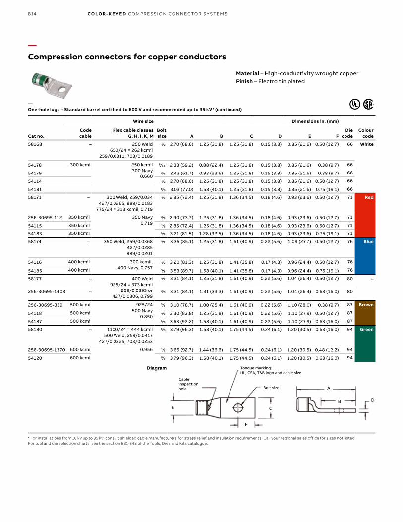
—Compression connectors for copper conductors
¥ For installations from 16 kV up to 35 kV, consult shielded cable manufacturers for stress relief and insulation requirements. Call your regional sales office for sizes not listed.For tool and die selection charts, see the section E31-E48 of the Tools, Dies and Kits catalogue.
Diagram
—One-hole lugs – Standard barrel certified to 600 V and recommended up to 35 kV¥ (continued)
Material – High-conductivity wrought copperFinish – Electro tin plated
E C
F
DB
A
Cableinspection hole Bolt size
Tongue marking: UL, CSA, T&B logo and cable size
B15
Cat no.
Wire size
Bolt size
Dimensions in. (mm)
Die code
Colour codeCode cable
Flex cable classes G, H, I, K, M A B C D E F
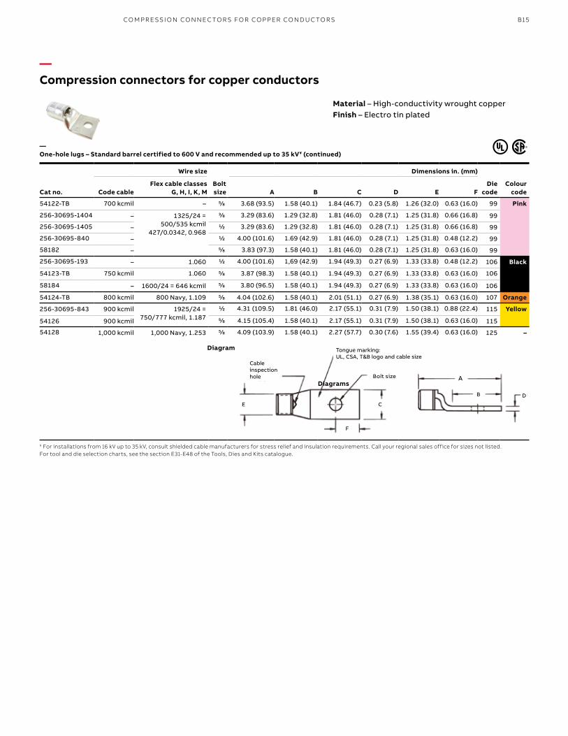
54122-TB 700 kcmil – 5/8 3.68 (93.5) 1.58 (40.1) 1.84 (46.7) 0.23 (5.8) 1.26 (32.0) 0.63 (16.0) 99 Pink
256-30695-1404 – 1325/24 = 500/535 kcmil
427/0.0342, 0.968
3/8 3.29 (83.6) 1.29 (32.8) 1.81 (46.0) 0.28 (7.1) 1.25 (31.8) 0.66 (16.8) 99
256-30695-1405 – 1/2 3.29 (83.6) 1.29 (32.8) 1.81 (46.0) 0.28 (7.1) 1.25 (31.8) 0.66 (16.8) 99
256-30695-840 – 1/2 4.00 (101.6) 1.69 (42.9) 1.81 (46.0) 0.28 (7.1) 1.25 (31.8) 0.48 (12.2) 99
58182 – 5/8 3.83 (97.3) 1.58 (40.1) 1.81 (46.0) 0.28 (7.1) 1.25 (31.8) 0.63 (16.0) 99
256-30695-193 – 1.060 1/2 4.00 (101.6) 1,69 (42.9) 1.94 (49.3) 0.27 (6.9) 1.33 (33.8) 0.48 (12.2) 106 Black
54123-TB 750 kcmil 1.060 5/8 3.87 (98.3) 1.58 (40.1) 1.94 (49.3) 0.27 (6.9) 1.33 (33.8) 0.63 (16.0) 106
58184 – 1600/24 = 646 kcmil 5/8 3.80 (96.5) 1.58 (40.1) 1.94 (49.3) 0.27 (6.9) 1.33 (33.8) 0.63 (16.0) 106
54124-TB 800 kcmil 800 Navy, 1.109 5/8 4.04 (102.6) 1.58 (40.1) 2.01 (51.1) 0.27 (6.9) 1.38 (35.1) 0.63 (16.0) 107 Orange
256-30695-843 900 kcmil 1925/24 = 750/777 kcmil, 1.187
1/2 4.31 (109.5) 1.81 (46.0) 2.17 (55.1) 0.31 (7.9) 1.50 (38.1) 0.88 (22.4) 115 Yellow
54126 900 kcmil 5/8 4.15 (105.4) 1.58 (40.1) 2.17 (55.1) 0.31 (7.9) 1.50 (38.1) 0.63 (16.0) 115
54128 1,000 kcmil 1,000 Navy, 1.253 5/8 4.09 (103.9) 1.58 (40.1) 2.27 (57.7) 0.30 (7.6) 1.55 (39.4) 0.63 (16.0) 125 –
—Compression connectors for copper conductors
¥ For installations from 16 kV up to 35 kV, consult shielded cable manufacturers for stress relief and insulation requirements. Call your regional sales office for sizes not listed.For tool and die selection charts, see the section E31-E48 of the Tools, Dies and Kits catalogue.
Diagram
—One-hole lugs – Standard barrel certified to 600 V and recommended up to 35 kV¥ (continued)
Material – High-conductivity wrought copperFinish – Electro tin plated
E C
F
DB
Bolt size A
Cableinspection hole
Tongue marking: UL, CSA, T&B logo and cable size
Diagrams
CO M PR E SSI O N CO N N EC TO R S FO R CO PPER CO N D U C TO R S
B16 CO LO R- K E Y E D CO M PR E SSI O N CO N N EC TO R S Y S TEMS
—Compression connectors for copper conductors
Material – High-conductivity wrought copperFinish – Electro tin plated
Cat no.
Wire size
Bolt size
Dimensions in. (mm)
Die code
Colour code
Code cable
Flex cable classes G, H, I, K, M B C D E F
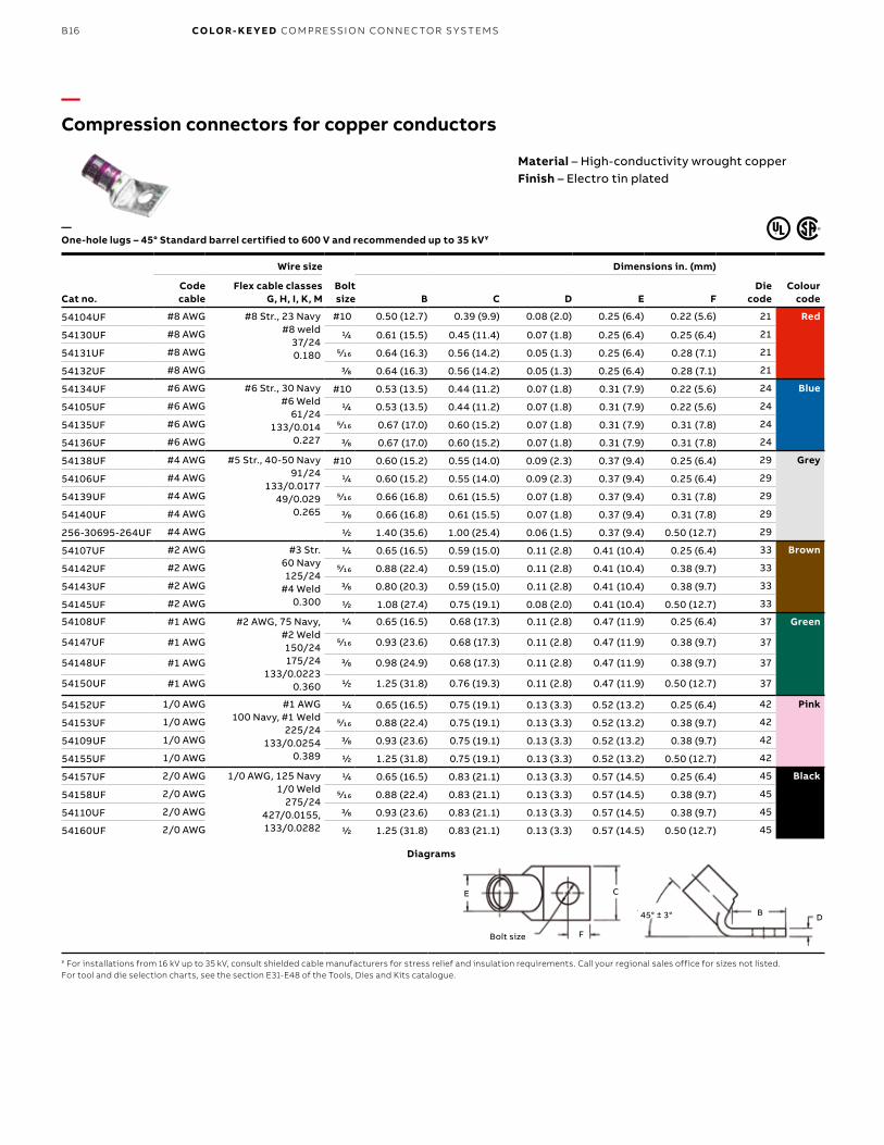
54104UF #8 AWG #8 Str., 23 Navy#8 weld
37/240.180
#10 0.50 (12.7) 0.39 (9.9) 0.08 (2.0) 0.25 (6.4) 0.22 (5.6) 21 Red
54130UF #8 AWG 1/4 0.61 (15.5) 0.45 (11.4) 0.07 (1.8) 0.25 (6.4) 0.25 (6.4) 21
54131UF #8 AWG 5⁄16 0.64 (16.3) 0.56 (14.2) 0.05 (1.3) 0.25 (6.4) 0.28 (7.1) 21
54132UF #8 AWG 3/8 0.64 (16.3) 0.56 (14.2) 0.05 (1.3) 0.25 (6.4) 0.28 (7.1) 21
54134UF #6 AWG #6 Str., 30 Navy#6 Weld
61/24133/0.014
0.227
#10 0.53 (13.5) 0.44 (11.2) 0.07 (1.8) 0.31 (7.9) 0.22 (5.6) 24 Blue
54105UF #6 AWG 1/4 0.53 (13.5) 0.44 (11.2) 0.07 (1.8) 0.31 (7.9) 0.22 (5.6) 24
54135UF #6 AWG 5⁄16 0.67 (17.0) 0.60 (15.2) 0.07 (1.8) 0.31 (7.9) 0.31 (7.8) 24
54136UF #6 AWG 3/8 0.67 (17.0) 0.60 (15.2) 0.07 (1.8) 0.31 (7.9) 0.31 (7.8) 24
54138UF #4 AWG #5 Str., 40-50 Navy91/24
133/0.017749/0.029
0.265
#10 0.60 (15.2) 0.55 (14.0) 0.09 (2.3) 0.37 (9.4) 0.25 (6.4) 29 Grey
54106UF #4 AWG 1/4 0.60 (15.2) 0.55 (14.0) 0.09 (2.3) 0.37 (9.4) 0.25 (6.4) 29
54139UF #4 AWG 5⁄16 0.66 (16.8) 0.61 (15.5) 0.07 (1.8) 0.37 (9.4) 0.31 (7.8) 29
54140UF #4 AWG 3/8 0.66 (16.8) 0.61 (15.5) 0.07 (1.8) 0.37 (9.4) 0.31 (7.8) 29
256-30695-264UF #4 AWG 1/2 1.40 (35.6) 1.00 (25.4) 0.06 (1.5) 0.37 (9.4) 0.50 (12.7) 29
54107UF #2 AWG #3 Str.60 Navy125/24
#4 Weld0.300
1/4 0.65 (16.5) 0.59 (15.0) 0.11 (2.8) 0.41 (10.4) 0.25 (6.4) 33 Brown
54142UF #2 AWG 5⁄16 0.88 (22.4) 0.59 (15.0) 0.11 (2.8) 0.41 (10.4) 0.38 (9.7) 33
54143UF #2 AWG 3/8 0.80 (20.3) 0.59 (15.0) 0.11 (2.8) 0.41 (10.4) 0.38 (9.7) 33
54145UF #2 AWG 1/2 1.08 (27.4) 0.75 (19.1) 0.08 (2.0) 0.41 (10.4) 0.50 (12.7) 33
54108UF #1 AWG #2 AWG, 75 Navy, #2 Weld150/24175/24
133/0.02230.360
1/4 0.65 (16.5) 0.68 (17.3) 0.11 (2.8) 0.47 (11.9) 0.25 (6.4) 37 Green
54147UF #1 AWG 5⁄16 0.93 (23.6) 0.68 (17.3) 0.11 (2.8) 0.47 (11.9) 0.38 (9.7) 37
54148UF #1 AWG 3/8 0.98 (24.9) 0.68 (17.3) 0.11 (2.8) 0.47 (11.9) 0.38 (9.7) 37
54150UF #1 AWG 1/2 1.25 (31.8) 0.76 (19.3) 0.11 (2.8) 0.47 (11.9) 0.50 (12.7) 37
54152UF 1/0 AWG #1 AWG100 Navy, #1 Weld
225/24133/0.0254
0.389
1/4 0.65 (16.5) 0.75 (19.1) 0.13 (3.3) 0.52 (13.2) 0.25 (6.4) 42 Pink
54153UF 1/0 AWG 5⁄16 0.88 (22.4) 0.75 (19.1) 0.13 (3.3) 0.52 (13.2) 0.38 (9.7) 42
54109UF 1/0 AWG 3/8 0.93 (23.6) 0.75 (19.1) 0.13 (3.3) 0.52 (13.2) 0.38 (9.7) 42
54155UF 1/0 AWG 1/2 1.25 (31.8) 0.75 (19.1) 0.13 (3.3) 0.52 (13.2) 0.50 (12.7) 42
54157UF 2/0 AWG 1/0 AWG, 125 Navy1/0 Weld
275/24427/0.0155, 133/0.0282
1/4 0.65 (16.5) 0.83 (21.1) 0.13 (3.3) 0.57 (14.5) 0.25 (6.4) 45 Black
54158UF 2/0 AWG 5⁄16 0.88 (22.4) 0.83 (21.1) 0.13 (3.3) 0.57 (14.5) 0.38 (9.7) 45
54110UF 2/0 AWG 3/8 0.93 (23.6) 0.83 (21.1) 0.13 (3.3) 0.57 (14.5) 0.38 (9.7) 45
54160UF 2/0 AWG 1/2 1.25 (31.8) 0.83 (21.1) 0.13 (3.3) 0.57 (14.5) 0.50 (12.7) 45
¥ For installations from 16 kV up to 35 kV, consult shielded cable manufacturers for stress relief and insulation requirements. Call your regional sales office for sizes not listed.For tool and die selection charts, see the section E31-E48 of the Tools, Dies and Kits catalogue.
—One-hole lugs – 45° Standard barrel certified to 600 V and recommended up to 35 kV¥
Diagrams
E C
F
DB45° ± 3°
Bolt size
B17
—Compression connectors for copper conductors
Cat no.
Wire size
Bolt size
Dimensions in. (mm)
Die code
Colour codeCode cable
Flex cable classes G, H, I, K, M B C D E F
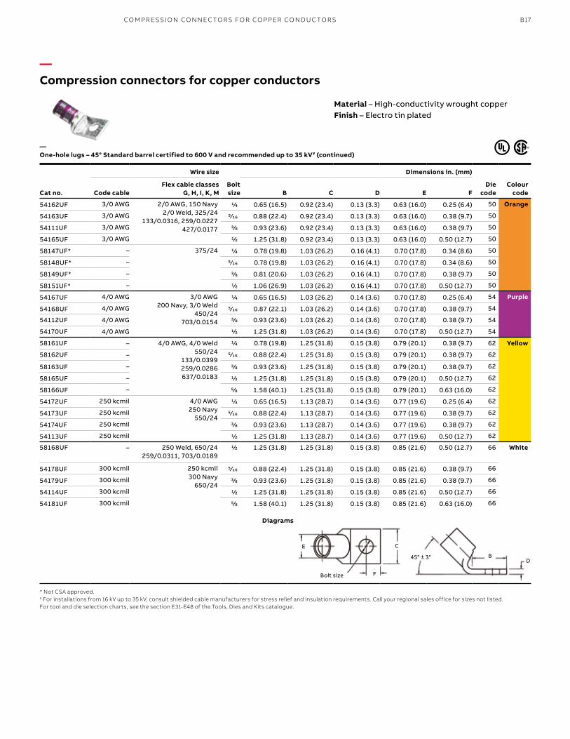
54162UF 3/0 AWG 2/0 AWG, 150 Navy2/0 Weld, 325/24
133/0.0316, 259/0.0227427/0.0177
1/4 0.65 (16.5) 0.92 (23.4) 0.13 (3.3) 0.63 (16.0) 0.25 (6.4) 50 Orange
54163UF 3/0 AWG 5⁄16 0.88 (22.4) 0.92 (23.4) 0.13 (3.3) 0.63 (16.0) 0.38 (9.7) 50
54111UF 3/0 AWG 3/8 0.93 (23.6) 0.92 (23.4) 0.13 (3.3) 0.63 (16.0) 0.38 (9.7) 50
54165UF 3/0 AWG 1/2 1.25 (31.8) 0.92 (23.4) 0.13 (3.3) 0.63 (16.0) 0.50 (12.7) 50
58147UF* – 375/24 1/4 0.78 (19.8) 1.03 (26.2) 0.16 (4.1) 0.70 (17.8) 0.34 (8.6) 50
58148UF* – 5⁄16 0.78 (19.8) 1.03 (26.2) 0.16 (4.1) 0.70 (17.8) 0.34 (8.6) 50
58149UF* – 3/8 0.81 (20.6) 1.03 (26.2) 0.16 (4.1) 0.70 (17.8) 0.38 (9.7) 50
58151UF* – 1/2 1.06 (26.9) 1.03 (26.2) 0.16 (4.1) 0.70 (17.8) 0.50 (12.7) 50
54167UF 4/0 AWG 3/0 AWG200 Navy, 3/0 Weld
450/24703/0.0154
1/4 0.65 (16.5) 1.03 (26.2) 0.14 (3.6) 0.70 (17.8) 0.25 (6.4) 54 Purple
54168UF 4/0 AWG 5⁄16 0.87 (22.1) 1.03 (26.2) 0.14 (3.6) 0.70 (17.8) 0.38 (9.7) 54
54112UF 4/0 AWG 3/8 0.93 (23.6) 1.03 (26.2) 0.14 (3.6) 0.70 (17.8) 0.38 (9.7) 54
54170UF 4/0 AWG 1/2 1.25 (31.8) 1.03 (26.2) 0.14 (3.6) 0.70 (17.8) 0.50 (12.7) 54
58161UF – 4/0 AWG, 4/0 Weld550/24
133/0.0399259/0.0286637/0.0183
1/4 0.78 (19.8) 1.25 (31.8) 0.15 (3.8) 0.79 (20.1) 0.38 (9.7) 62 Yellow
58162UF – 5⁄16 0.88 (22.4) 1.25 (31.8) 0.15 (3.8) 0.79 (20.1) 0.38 (9.7) 62
58163UF – 3/8 0.93 (23.6) 1.25 (31.8) 0.15 (3.8) 0.79 (20.1) 0.38 (9.7) 62
58165UF – 1/2 1.25 (31.8) 1.25 (31.8) 0.15 (3.8) 0.79 (20.1) 0.50 (12.7) 62
58166UF – 5/8 1.58 (40.1) 1.25 (31.8) 0.15 (3.8) 0.79 (20.1) 0.63 (16.0) 62
54172UF 250 kcmil 4/0 AWG250 Navy
550/24
1/4 0.65 (16.5) 1.13 (28.7) 0.14 (3.6) 0.77 (19.6) 0.25 (6.4) 62
54173UF 250 kcmil 5⁄16 0.88 (22.4) 1.13 (28.7) 0.14 (3.6) 0.77 (19.6) 0.38 (9.7) 62
54174UF 250 kcmil 3/8 0.93 (23.6) 1.13 (28.7) 0.14 (3.6) 0.77 (19.6) 0.38 (9.7) 62
54113UF 250 kcmil 1/2 1.25 (31.8) 1.13 (28.7) 0.14 (3.6) 0.77 (19.6) 0.50 (12.7) 62
58168UF – 250 Weld, 650/24259/0.0311, 703/0.0189
1/2 1.25 (31.8) 1.25 (31.8) 0.15 (3.8) 0.85 (21.6) 0.50 (12.7) 66 White
54178UF 300 kcmil 250 kcmil300 Navy
650/24
5⁄16 0.88 (22.4) 1.25 (31.8) 0.15 (3.8) 0.85 (21.6) 0.38 (9.7) 66
54179UF 300 kcmil 3/8 0.93 (23.6) 1.25 (31.8) 0.15 (3.8) 0.85 (21.6) 0.38 (9.7) 66
54114UF 300 kcmil 1/2 1.25 (31.8) 1.25 (31.8) 0.15 (3.8) 0.85 (21.6) 0.50 (12.7) 66
54181UF 300 kcmil 5/8 1.58 (40.1) 1.25 (31.8) 0.15 (3.8) 0.85 (21.6) 0.63 (16.0) 66
—One-hole lugs – 45° Standard barrel certified to 600 V and recommended up to 35 kV¥ (continued)
* Not CSA approved.¥ For installations from 16 kV up to 35 kV, consult shielded cable manufacturers for stress relief and insulation requirements. Call your regional sales office for sizes not listed.For tool and die selection charts, see the section E31-E48 of the Tools, Dies and Kits catalogue.
Diagrams
Material – High-conductivity wrought copperFinish – Electro tin plated
C
F
DB45° ± 3°
Bolt size
E
CO M PR E SSI O N CO N N EC TO R S FO R CO PPER CO N D U C TO R S
B18 CO LO R- K E Y E D CO M PR E SSI O N CO N N EC TO R S Y S TEMS
—Compression connectors for copper conductors
Cat no.
Wire size
Bolt size
Dimensions in. (mm)
Die code
Colour codeCode cable
Flex cable classes G, H, I, K, M B C D E F
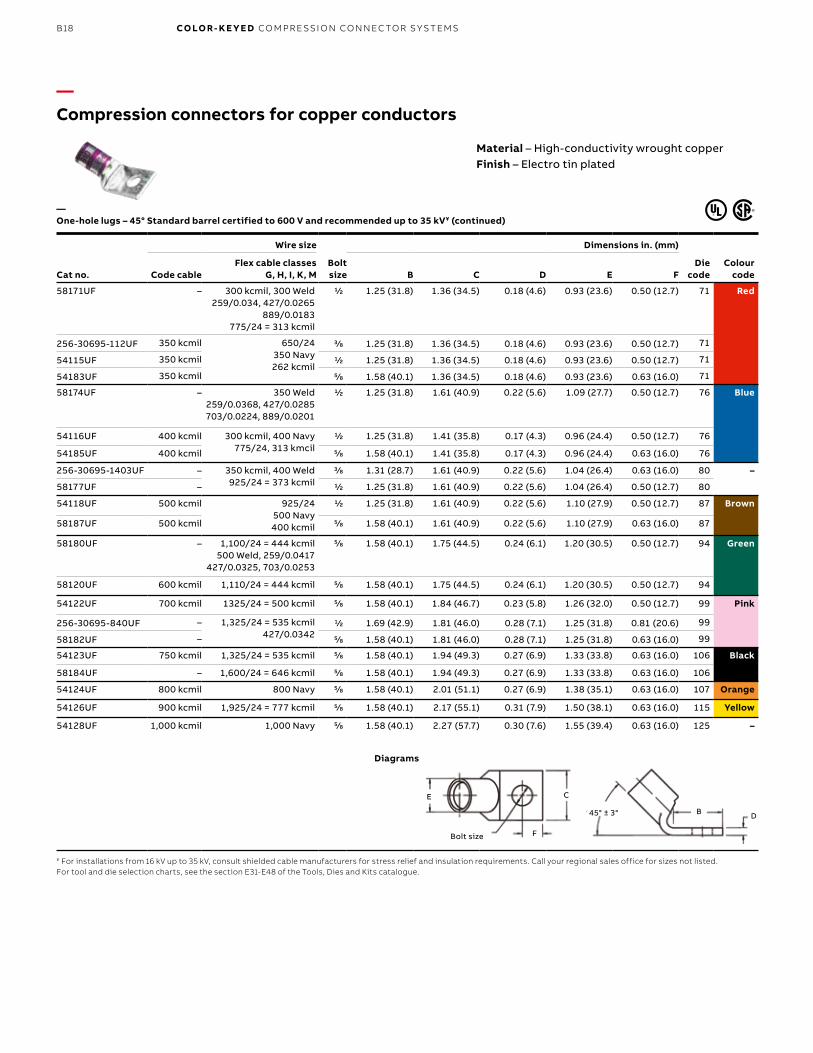
58171UF – 300 kcmil, 300 Weld259/0.034, 427/0.0265
889/0.0183775/24 = 313 kcmil
1/2 1.25 (31.8) 1.36 (34.5) 0.18 (4.6) 0.93 (23.6) 0.50 (12.7) 71 Red
256-30695-112UF 350 kcmil 650/24350 Navy262 kcmil
3/8 1.25 (31.8) 1.36 (34.5) 0.18 (4.6) 0.93 (23.6) 0.50 (12.7) 71
54115UF 350 kcmil 1/2 1.25 (31.8) 1.36 (34.5) 0.18 (4.6) 0.93 (23.6) 0.50 (12.7) 71
54183UF 350 kcmil 5/8 1.58 (40.1) 1.36 (34.5) 0.18 (4.6) 0.93 (23.6) 0.63 (16.0) 71
58174UF – 350 Weld259/0.0368, 427/0.0285703/0.0224, 889/0.0201
1/2 1.25 (31.8) 1.61 (40.9) 0.22 (5.6) 1.09 (27.7) 0.50 (12.7) 76 Blue
54116UF 400 kcmil 300 kcmil, 400 Navy775/24, 313 kmcil
1/2 1.25 (31.8) 1.41 (35.8) 0.17 (4.3) 0.96 (24.4) 0.50 (12.7) 76
54185UF 400 kcmil 5/8 1.58 (40.1) 1.41 (35.8) 0.17 (4.3) 0.96 (24.4) 0.63 (16.0) 76
256-30695-1403UF – 350 kcmil, 400 Weld925/24 = 373 kcmil
3/8 1.31 (28.7) 1.61 (40.9) 0.22 (5.6) 1.04 (26.4) 0.63 (16.0) 80 –
58177UF – 1/2 1.25 (31.8) 1.61 (40.9) 0.22 (5.6) 1.04 (26.4) 0.50 (12.7) 80
54118UF 500 kcmil 925/24500 Navy400 kcmil
1/2 1.25 (31.8) 1.61 (40.9) 0.22 (5.6) 1.10 (27.9) 0.50 (12.7) 87 Brown
58187UF 500 kcmil 5/8 1.58 (40.1) 1.61 (40.9) 0.22 (5.6) 1.10 (27.9) 0.63 (16.0) 87
58180UF – 1,100/24 = 444 kcmil500 Weld, 259/0.0417
427/0.0325, 703/0.0253
5/8 1.58 (40.1) 1.75 (44.5) 0.24 (6.1) 1.20 (30.5) 0.50 (12.7) 94 Green
58120UF 600 kcmil 1,110/24 = 444 kcmil 5/8 1.58 (40.1) 1.75 (44.5) 0.24 (6.1) 1.20 (30.5) 0.50 (12.7) 94
54122UF 700 kcmil 1325/24 = 500 kcmil 5/8 1.58 (40.1) 1.84 (46.7) 0.23 (5.8) 1.26 (32.0) 0.50 (12.7) 99 Pink
256-30695-840UF – 1,325/24 = 535 kcmil427/0.0342
1/2 1.69 (42.9) 1.81 (46.0) 0.28 (7.1) 1.25 (31.8) 0.81 (20.6) 99
58182UF – 5/8 1.58 (40.1) 1.81 (46.0) 0.28 (7.1) 1.25 (31.8) 0.63 (16.0) 99
54123UF 750 kcmil 1,325/24 = 535 kcmil 5/8 1.58 (40.1) 1.94 (49.3) 0.27 (6.9) 1.33 (33.8) 0.63 (16.0) 106 Black
58184UF – 1,600/24 = 646 kcmil 5/8 1.58 (40.1) 1.94 (49.3) 0.27 (6.9) 1.33 (33.8) 0.63 (16.0) 106
54124UF 800 kcmil 800 Navy 5/8 1.58 (40.1) 2.01 (51.1) 0.27 (6.9) 1.38 (35.1) 0.63 (16.0) 107 Orange
54126UF 900 kcmil 1,925/24 = 777 kcmil 5/8 1.58 (40.1) 2.17 (55.1) 0.31 (7.9) 1.50 (38.1) 0.63 (16.0) 115 Yellow
54128UF 1,000 kcmil 1,000 Navy 5/8 1.58 (40.1) 2.27 (57.7) 0.30 (7.6) 1.55 (39.4) 0.63 (16.0) 125 –
¥ For installations from 16 kV up to 35 kV, consult shielded cable manufacturers for stress relief and insulation requirements. Call your regional sales office for sizes not listed.For tool and die selection charts, see the section E31-E48 of the Tools, Dies and Kits catalogue.
—One-hole lugs – 45° Standard barrel certified to 600 V and recommended up to 35 kV¥ (continued)
Diagrams
Material – High-conductivity wrought copperFinish – Electro tin plated
E C
F
DB45° ± 3°
Bolt size
B19
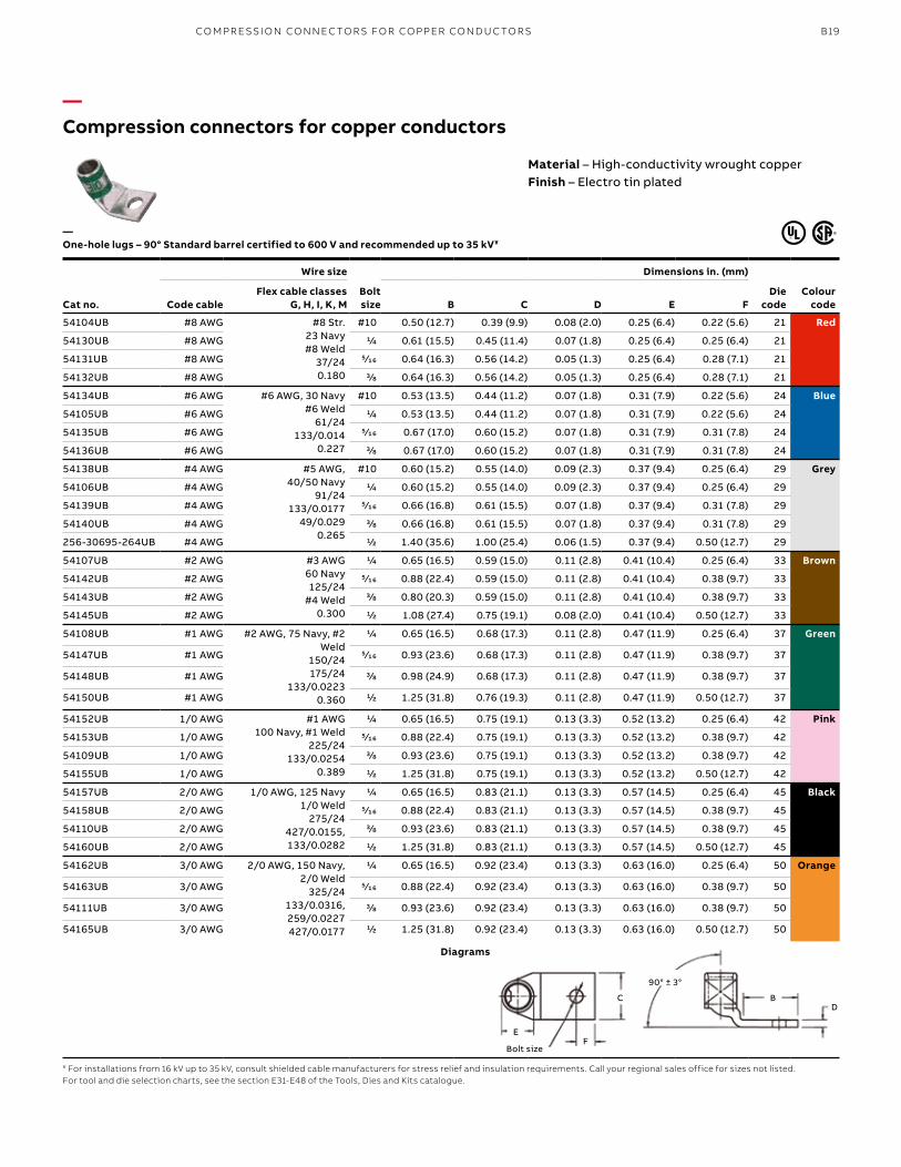
—Compression connectors for copper conductors
Material – High-conductivity wrought copperFinish – Electro tin plated
Cat no.
Wire size
Bolt size
Dimensions in. (mm)
Die code
Colour codeCode cable
Flex cable classes G, H, I, K, M B C D E F
54104UB #8 AWG #8 Str.23 Navy#8 Weld
37/240.180
#10 0.50 (12.7) 0.39 (9.9) 0.08 (2.0) 0.25 (6.4) 0.22 (5.6) 21 Red
54130UB #8 AWG 1/4 0.61 (15.5) 0.45 (11.4) 0.07 (1.8) 0.25 (6.4) 0.25 (6.4) 21
54131UB #8 AWG 5⁄16 0.64 (16.3) 0.56 (14.2) 0.05 (1.3) 0.25 (6.4) 0.28 (7.1) 21
54132UB #8 AWG 3/8 0.64 (16.3) 0.56 (14.2) 0.05 (1.3) 0.25 (6.4) 0.28 (7.1) 21
54134UB #6 AWG #6 AWG, 30 Navy#6 Weld
61/24133/0.014
0.227
#10 0.53 (13.5) 0.44 (11.2) 0.07 (1.8) 0.31 (7.9) 0.22 (5.6) 24 Blue
54105UB #6 AWG 1/4 0.53 (13.5) 0.44 (11.2) 0.07 (1.8) 0.31 (7.9) 0.22 (5.6) 24
54135UB #6 AWG 5⁄16 0.67 (17.0) 0.60 (15.2) 0.07 (1.8) 0.31 (7.9) 0.31 (7.8) 24
54136UB #6 AWG 3/8 0.67 (17.0) 0.60 (15.2) 0.07 (1.8) 0.31 (7.9) 0.31 (7.8) 24
54138UB #4 AWG #5 AWG, 40/50 Navy
91/24133/0.0177
49/0.0290.265
#10 0.60 (15.2) 0.55 (14.0) 0.09 (2.3) 0.37 (9.4) 0.25 (6.4) 29 Grey
54106UB #4 AWG 1/4 0.60 (15.2) 0.55 (14.0) 0.09 (2.3) 0.37 (9.4) 0.25 (6.4) 29
54139UB #4 AWG 5⁄16 0.66 (16.8) 0.61 (15.5) 0.07 (1.8) 0.37 (9.4) 0.31 (7.8) 29
54140UB #4 AWG 3/8 0.66 (16.8) 0.61 (15.5) 0.07 (1.8) 0.37 (9.4) 0.31 (7.8) 29
256-30695-264UB #4 AWG 1/2 1.40 (35.6) 1.00 (25.4) 0.06 (1.5) 0.37 (9.4) 0.50 (12.7) 29
54107UB #2 AWG #3 AWG60 Navy125/24
#4 Weld0.300
1/4 0.65 (16.5) 0.59 (15.0) 0.11 (2.8) 0.41 (10.4) 0.25 (6.4) 33 Brown
54142UB #2 AWG 5⁄16 0.88 (22.4) 0.59 (15.0) 0.11 (2.8) 0.41 (10.4) 0.38 (9.7) 33
54143UB #2 AWG 3/8 0.80 (20.3) 0.59 (15.0) 0.11 (2.8) 0.41 (10.4) 0.38 (9.7) 33
54145UB #2 AWG 1/2 1.08 (27.4) 0.75 (19.1) 0.08 (2.0) 0.41 (10.4) 0.50 (12.7) 33
54108UB #1 AWG #2 AWG, 75 Navy, #2 Weld
150/24175/24
133/0.02230.360
1/4 0.65 (16.5) 0.68 (17.3) 0.11 (2.8) 0.47 (11.9) 0.25 (6.4) 37 Green
54147UB #1 AWG 5⁄16 0.93 (23.6) 0.68 (17.3) 0.11 (2.8) 0.47 (11.9) 0.38 (9.7) 37
54148UB #1 AWG 3/8 0.98 (24.9) 0.68 (17.3) 0.11 (2.8) 0.47 (11.9) 0.38 (9.7) 37
54150UB #1 AWG 1/2 1.25 (31.8) 0.76 (19.3) 0.11 (2.8) 0.47 (11.9) 0.50 (12.7) 37
54152UB 1/0 AWG #1 AWG100 Navy, #1 Weld
225/24133/0.0254
0.389
1/4 0.65 (16.5) 0.75 (19.1) 0.13 (3.3) 0.52 (13.2) 0.25 (6.4) 42 Pink
54153UB 1/0 AWG 5⁄16 0.88 (22.4) 0.75 (19.1) 0.13 (3.3) 0.52 (13.2) 0.38 (9.7) 42
54109UB 1/0 AWG 3/8 0.93 (23.6) 0.75 (19.1) 0.13 (3.3) 0.52 (13.2) 0.38 (9.7) 42
54155UB 1/0 AWG 1/2 1.25 (31.8) 0.75 (19.1) 0.13 (3.3) 0.52 (13.2) 0.50 (12.7) 42
54157UB 2/0 AWG 1/0 AWG, 125 Navy1/0 Weld
275/24427/0.0155, 133/0.0282
1/4 0.65 (16.5) 0.83 (21.1) 0.13 (3.3) 0.57 (14.5) 0.25 (6.4) 45 Black
54158UB 2/0 AWG 5⁄16 0.88 (22.4) 0.83 (21.1) 0.13 (3.3) 0.57 (14.5) 0.38 (9.7) 45
54110UB 2/0 AWG 3/8 0.93 (23.6) 0.83 (21.1) 0.13 (3.3) 0.57 (14.5) 0.38 (9.7) 45
54160UB 2/0 AWG 1/2 1.25 (31.8) 0.83 (21.1) 0.13 (3.3) 0.57 (14.5) 0.50 (12.7) 45
54162UB 3/0 AWG 2/0 AWG, 150 Navy, 2/0 Weld
325/24133/0.0316, 259/0.0227427/0.0177
1/4 0.65 (16.5) 0.92 (23.4) 0.13 (3.3) 0.63 (16.0) 0.25 (6.4) 50 Orange
54163UB 3/0 AWG 5⁄16 0.88 (22.4) 0.92 (23.4) 0.13 (3.3) 0.63 (16.0) 0.38 (9.7) 50
54111UB 3/0 AWG 3/8 0.93 (23.6) 0.92 (23.4) 0.13 (3.3) 0.63 (16.0) 0.38 (9.7) 50
54165UB 3/0 AWG 1/2 1.25 (31.8) 0.92 (23.4) 0.13 (3.3) 0.63 (16.0) 0.50 (12.7) 50
—One-hole lugs – 90° Standard barrel certified to 600 V and recommended up to 35 kV¥
¥ For installations from 16 kV up to 35 kV, consult shielded cable manufacturers for stress relief and insulation requirements. Call your regional sales office for sizes not listed.For tool and die selection charts, see the section E31-E48 of the Tools, Dies and Kits catalogue.
Diagrams
E
C
F
DB
90° ± 3°
Bolt size
CO M PR E SSI O N CO N N EC TO R S FO R CO PPER CO N D U C TO R S
B20 CO LO R- K E Y E D CO M PR E SSI O N CO N N EC TO R S Y S TEMS
—Compression connectors for copper conductors
Cat no.
Wire size
Bolt size
Dimensions in. (mm)
Die code
Colour code
Code cable
Flex cable classes G, H, I, K, M B C D E F
54167UB – 3/0 AWG, 200 Navy, 3/0 Weld
450/24703/0.0154
1/4 0.65 (16.5) 1.03 (26.2) 0.14 (3.6) 0.70 (17.8) 0.34 (8.6) 54 Purple
54168UB – 5⁄16 0.87 (22.1) 1.03 (26.2) 0.14 (3.6) 0.70 (17.8) 0.34 (8.6) 54
54112UB – 3/8 0.93 (23.6) 1.03 (26.2) 0.14 (3.6) 0.70 (17.8) 0.38 (9.7) 54
54170UB – 1/2 1.25 (31.8) 1.03 (26.2) 0.14 (3.6) 0.70 (17.8) 0.50 (12.7) 54
58161UB 4/0 AWG 3/0 AWG, 4/0 Weld550/24
133/0.0399259/0.0286637/0.0183
1/4 0.78 (19.8) 1.25 (31.8) 0.15 (3.8) 0.79 (20.1) 0.38 (9.7) 62 Yellow
58162UB 4/0 AWG 5⁄16 0.88 (22.4) 1.25 (31.8) 0.15 (3.8) 0.79 (20.1) 0.38 (9.7) 62
58163UB 4/0 AWG 3/8 0.93 (23.6) 1.25 (31.8) 0.15 (3.8) 0.79 (20.1) 0.38 (9.7) 62
58165UB 4/0 AWG 1/2 1.25 (31.8) 1.25 (31.8) 0.15 (3.8) 0.79 (20.1) 0.50 (12.7) 62
58166UB 4/0 AWG 5/8 1.58 (40.1) 1.25 (31.8) 0.15 (3.8) 0.79 (20.1) 0.63 (16.0) 62
54172UB 250 kcmil 4/0 AWG250 Navy
550/24
1/4 0.65 (16.5) 1.13 (28.7) 0.14 (3.6) 0.77 (19.6) 0.25 (6.4) 62
54173UB 250 kcmil 5⁄16 0.88 (22.4) 1.13 (28.7) 0.14 (3.6) 0.77 (19.6) 0.38 (9.7) 62
54174UB 250 kcmil 3/8 0.93 (23.6) 1.13 (28.7) 0.14 (3.6) 0.77 (19.6) 0.38 (9.7) 62
54113UB 250 kcmil 1/2 1.25 (31.8) 1.13 (28.7) 0.14 (3.6) 0.77 (19.6) 0.50 (12.7) 62
58168UB – 250 Weld650/24 = 262 kcmil
259/0.0311, 703/0.0189
1/2 1.25 (31.8) 1.25 (31.8) 0.15 (3.8) 0.85 (21.6) 0.50 (12.7) 66 White
54178UB 300 kcmil 250 kcmil300 Navy
650/24
5⁄16 0.88 (22.4) 1.25 (31.8) 0.15 (3.8) 0.85 (21.6) 0.38 (9.7) 66
54179UB 300 kcmil 3/8 0.93 (23.6) 1.25 (31.8) 0.15 (3.8) 0.85 (21.6) 0.38 (9.7) 66
54114UB 300 kcmil 1/2 1.25 (31.8) 1.25 (31.8) 0.15 (3.8) 0.85 (21.6) 0.50 (12.7) 66
54181UB 300 kcmil 5/8 1.58 (40.1) 1.25 (31.8) 0.15 (3.8) 0.85 (21.6) 0.63 (16.0) 66
58171UB – 300 Weld, 259/0.034427/0.0265, 889/0.0183
775/24 = 313 kcmil
1/2 1.25 (31.8) 1.36 (34.5) 0.18 (4.6) 0.93 (23.6) 0.50 (12.7) 71 Red
256-30695-112UB 350 kcmil 650/24, 350 Navy262 kcmil
3/8 1.25 (31.8) 1.36 (34.5) 0.18 (4.6) 0.93 (23.6) 0.50 (12.7) 71
54115UB 350 kcmil 1/2 1.25 (31.8) 1.36 (34.5) 0.18 (4.6) 0.93 (23.6) 0.50 (12.7) 71
54183UB 350 kcmil 5/8 1.58 (40.1) 1.36 (34.5) 0.18 (4.6) 0.93 (23.6) 0.63 (16.0) 71
58174UB – 350 Weld259/0.0368, 427/0.0285703/0.0224, 889/0.0201
1/2 1.25 (31.8) 1.61 (40.9) 0.22 (5.6) 1.09 (27.7) 0.50 (12.7) 76 Blue
54116UB 400 kcmil 300 kcmil, 400 Navy775/24, 313 kcmil
1/2 1.25 (31.8) 1.41 (35.8) 0.17 (4.3) 0.96 (24.4) 0.50 (12.7) 76
54185UB 400 kcmil 5/8 1.58 (40.1) 1.41 (35.8) 0.17 (4.3) 0.96 (24.4) 0.63 (16.0) 76
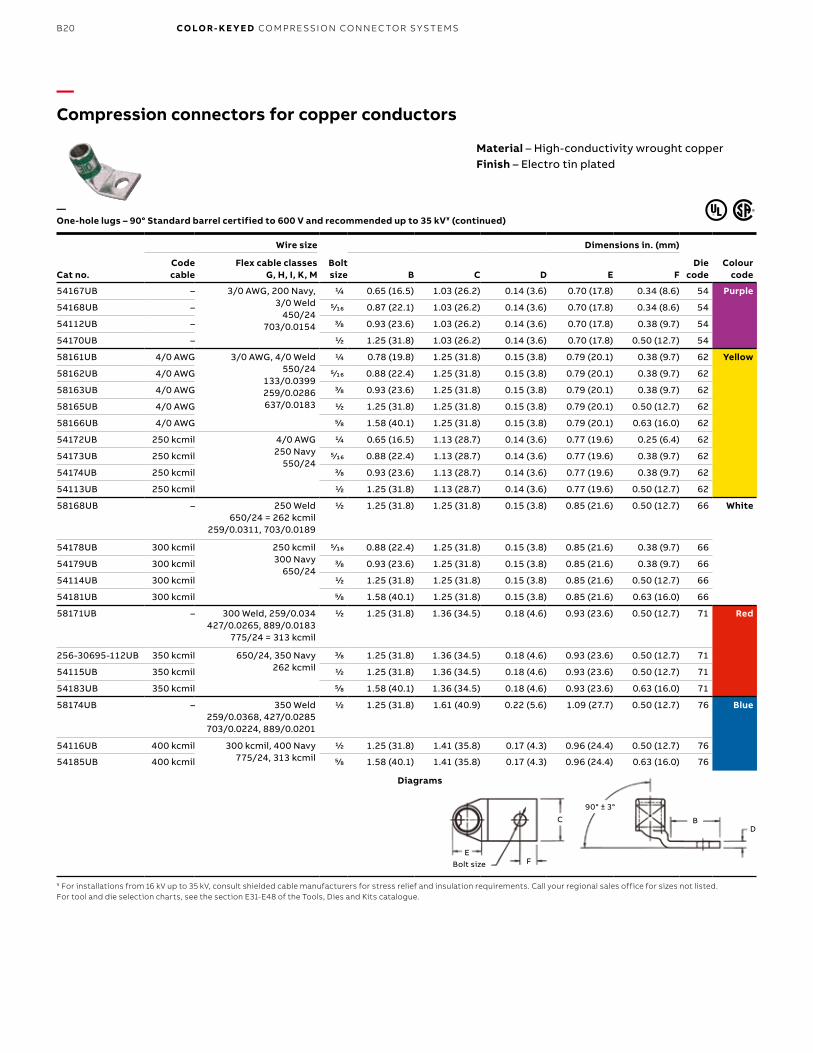
—One-hole lugs – 90° Standard barrel certified to 600 V and recommended up to 35 kV¥ (continued)
¥ For installations from 16 kV up to 35 kV, consult shielded cable manufacturers for stress relief and insulation requirements. Call your regional sales office for sizes not listed.For tool and die selection charts, see the section E31-E48 of the Tools, Dies and Kits catalogue.
Diagrams
Material – High-conductivity wrought copperFinish – Electro tin plated
C
F
DB
90° ± 3°
Bolt sizeE
B21
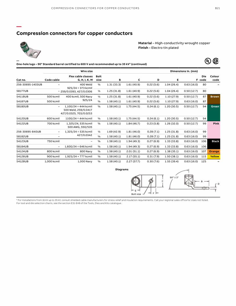
—Compression connectors for copper conductors
Cat no.
Wire size
Bolt size
Dimensions in. (mm)
Die code
Colour codeCode cable
Flex cable classes G, H, I, K, M B C D E F
256-30695-1403UB – 400 Weld925/24 = 373 kcmil
259/0.0393, 427/0.0306
3/8 1.31 (33.3) 1.61 (40.9) 0.22 (5.6) 1.04 (26.4) 0.63 (16.0) 80 –
58177UB – 1/2 1.25 (31.8) 1.61 (40.9) 0.22 (5.6) 1.04 (26.4) 0.50 (12.7) 80
54118UB 500 kcmil 400 kcmil, 500 Navy925/24
1/2 1.25 (31.8) 1.61 (40.9) 0.22 (5.6) 1.10 (27.9) 0.50 (12.7) 87 Brown
54187UB 500 kcmil 5/8 1.58 (40.1) 1.61 (40.9) 0.22 (5.6) 1.10 (27.9) 0.63 (16.0) 87
58180UB – 1,100/24 = 444 kcmil500 Weld, 259/0.0417
427/0.0325, 703/0.0253
5/8 1.58 (40.1) 1.75 (44.5) 0.24 (6.1) 1.20 (30.5) 0.50 (12.7) 94 Green
54120UB 600 kcmil 1100/24 = 444 kcmil 5/8 1.58 (40.1) 1.75 (44.5) 0.24 (6.1) 1.20 (30.5) 0.50 (12.7) 94
54122UB 700 kcmil 1,325/24, 535 kcmil500 AWG, 550/535
5/8 1.58 (40.1) 1.84 (46.7) 0.23 (5.8) 1.26 (32.0) 0.50 (12.7) 99 Pink
256-30695-840UB – 1,325/24 = 535 kcmil427/0.0342
1/2 1.69 (42.9) 1.81 (46.0) 0.28 (7.1) 1.25 (31.8) 0.63 (16.0) 99
58182UB – 5/8 1.58 (40.1) 1.81 (46.0) 0.28 (7.1) 1.25 (31.8) 0.63 (16.0) 99
54123UB 750 kcmil – 5/8 1.58 (40.1) 1.94 (49.3) 0.27 (6.9) 1.33 (33.8) 0.63 (16.0) 106 Black
58184UB – 1,600/24 = 646 kcmil 5/8 1.58 (40.1) 1.94 (49.3) 0.27 (6.9) 1.33 (33.8) 0.63 (16.0) 106
54124UB 800 kcmil 800 Navy 5/8 1.58 (40.1) 2.01 (51.1) 0.27 (6.9) 1.38 (35.1) 0.63 (16.0) 107 Orange
54126UB 900 kcmil 1,925/24 = 777 kcmil 5/8 1.58 (40.1) 2.17 (55.1) 0.31 (7.9) 1.50 (38.1) 0.63 (16.0) 115 Yellow
54128UB 1,000 kcmil 1,000 Navy 5/8 1.58 (40.1) 2.27 (57.7) 0.30 (7.6) 1.55 (39.4) 0.63 (16.0) 125 –
—One-hole lugs – 90° Standard barrel certified to 600 V and recommended up to 35 kV¥ (continued)
¥ For installations from 16 kV up to 35 kV, consult shielded cable manufacturers for stress relief and insulation requirements. Call your regional sales office for sizes not listed.For tool and die selection charts, see the section E31-E48 of the Tools, Dies and Kits catalogue.
Diagrams
Material – High-conductivity wrought copperFinish – Electro tin plated
C
F
DB
90° ± 3°
Bolt sizeE
CO M PR E SSI O N CO N N EC TO R S FO R CO PPER CO N D U C TO R S
B22 CO LO R- K E Y E D CO M PR E SSI O N CO N N EC TO R S Y S TEMS
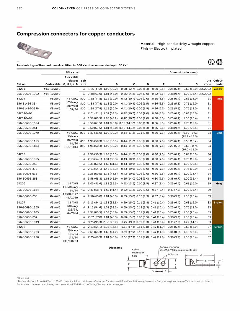
—Compression connectors for copper conductors
Material – High-conductivity wrought copperFinish – Electro tin plated
Cat no.
Wire size
Bolt size
Dimensions in. (mm)
Die code
Colour codeCode cable
Flex cable classes
G, H, I, K, M A B C D E F G
54201 #14–10 AWG – 1/4 1.86 (47.2) 1.19 (30.2) 0.50 (12.7) 0.05 (1.3) 0.20 (5.1) 0.25 (6.4) 0.63 (16.0) ERG2002 Yellow
256-30695-1302 #14–10 AWG 3/8 2.48 (63.0) 1.81 (46.0) 0.56 (14.2) 0.04 (1.0) 0.22 (5.6) 0.38 (9.7) 1.00 (25.4) ERG2002
54204 #8 AWG #8 AWG, 23 Navy#8 Weld
37/24
#10 1.88 (47.8) 1.18 (30.0) 0.42 (10.7) 0.08 (2.0) 0.26 (6.6) 0.25 (6.4) 0.63 (16.0) 21 Red
256-31426-33* #8 AWG #10 1.88 (47.8) 1.18 (30.0) 0.41 (10.4) 0.06 (1.5) 0.26 (6.6) 0.23 (5.8) 0.75 (19.0) 21
256-31426-33PH #8 AWG #10 1.88 (47.8) 1.18 (30.0) 0.41 (10.4) 0.06 (1.5) 0.26 (6.6) 0.23 (5.8) 0.75 (19.0) 21
542040410 #8 AWG 1/4 2.01 (51.1) 1.31 (33.3) 0.42 (10.7) 0.08 (2.0) 0.26 (6.6) 0.25 (6.4) 0.63 (16.0) 21
542040416 #8 AWG 1/4 2.38 (60.5) 1.68 (42.7) 0.42 (10.7) 0.08 (2.0) 0.26 (6.6) 0.25 (6.4) 1.00 (25.4) 21
256-30695-1094 #8 AWG 1/4 2.50 (63.5) 1.81 (46.0) 0.56 (14.22) 0.05 (1.3) 0.26 (6.6) 0.25 (6.4) 0.75 (19.0) 21
256-30695-251 #8 AWG 3/8 2.50 (63.5) 1.81 (46.0) 0.56 (14.22) 0.05 (1.3) 0.26 (6.6) 0.38 (9.7) 1.00 (25.4) 21
256-30695-1070 #6 AWG #6 AWG, 30 Navy#6 Weld
61/24133/0.014
#12 1.81 (46.0) 1.19 (30.2) 0.44 (11.2) 0.11 (2.8) 0.30 (7.6) 0.25 (6.4) 0.50 – 0.63 (12.7 – 16.0)
24 Blue
256-30695-1153 #6 AWG #10 1.98 (50.3) 1.28 (32.5) 0.44 (11.2) 0.08 (2.0) 0.30 (7.6) 0.25 (6.4) 0.50 (12.7) 24
256-30695-1183 #6 AWG #10 1.98 (50.3) 1.19 (30.2) 0.44 (11.2) 0.08 (2.0) 0.30 (7.6) 0.22 (5.6) 0.63 – 0.75 (16.0 – 19.0)
24
54205 #6 AWG 1/4 1.98 (50.3) 1.28 (32.5) 0.44 (11.2) 0.08 (2.0) 0.30 (7.6) 0.25 (6.4) 0.63 (16.0) 24
256-30695-1095 #6 AWG 1/4 2.13 (54.1) 1.31 (33.3) 0.43 (10.9) 0.08 (2.0) 0.30 (7.6) 0.25 (6.4) 0.75 (19.0) 24
256-30695-252 #6 AWG 1/4 2.38 (60.5) 1.63 (41.4) 0.43 (10.9) 0.08 (2.0) 0.30 (7.6) 0.25 (6.4) 1.00 (25.4) 24
256-30695-372 #6 AWG 1/4 2.13 (54.1) 1.43 (36.3) 0.43 (10.9) 0.08 (2.0) 0.30 (7.6) 0.25 (6.4) 0.75 (19.0) 24
256-30695-913 #6 AWG 1/4 2.38 (60.5) 1.75 (44.5) 0.43 (10.9) 0.08 (2.0) 0.30 (7.6) 0.25 (6.4) 1.00 (25.4) 24
256-30695-253 #6 AWG 3/8 2.58 (65.3) 1.81 (45.9) 0.55 (14.0) 0.08 (2.0) 0.30 (7.6) 0.38 (9.7) 1.00 (25.4) 24
54206 #4 AWG #5 AWG40-50 Navy
91/24133/0.0177
49/0.029
1/4 2.03 (51.6) 1.28 (32.5) 0.52 (13.2) 0.10 (2.5) 0.37 (9.4) 0.25 (6.4) 0.63 (16.0) 29 Grey
256-30695-1184 #4 AWG 5⁄16 2.31 (58.7) 1.63 (41.4) 0.52 (13.2) 0.10 (2.5) 0.37 (9.4) 0.31 (7.9) 1.00 (25.4) 29
256-30695-255 #4 AWG 3/8 2.56 (65.0) 1.81 (45.9) 0.59 (15.0) 0.09 (2.3) 0.37 (9.4) 0.38 (9.7) 1.00 (25.4) 29
54207 #2 AWG #3 AWG60 Navy125/24, #4 Weld
1/4 2.13 (54.1) 1.28 (32.5) 0.59 (15.0) 0.11 (2.8) 0.41 (10.4) 0.25 (6.4) 0.63 (16.0) 33 Brown
256-30695-1355 #2 AWG 1/4 2.15 (54.6) 1.31 (33.3) 0.59 (15.0) 0.13 (3.3) 0.41 (10.4) 0.25 (6.4) 0.75 (19.0) 33
256-30695-1185 #2 AWG 1/4 2.38 (60.5) 1.53 (38.9) 0.59 (15.0) 0.11 (2.8) 0.41 (10.4) 0.25 (6.4) 1.00 (25.4) 33
256-30695-257 #2 AWG 3/8 2.67 (67.8) 1.81 (45.9) 0.60 (15.2) 0.10 (2.5) 0.41 (10.4) 0.38 (9.7) 1.00 (25.4) 33
256-30695-1049 #2 AWG 1/2 3.75 (95.3) 2.88 (73.2) 0.75 (19.1) 0.09 (2.3) 0.41 (10.4) 0.31 (7.9) 1.75 (44.5) 33
54208 #1 AWG #2 AWG, 75 Navy150/24175/24
133/0.0223
1/4 2.13 (54.1) 1.28 (32.5) 0.68 (17.3) 0.11 (2.8) 0.47 (11.9) 0.25 (6.4) 0.63 (16.0) 37 Green
256-30695-1233 #1 AWG 5⁄16 2.69 (68.3) 1.62 (41.2) 0.69 (17.5) 0.13 (3.3) 0.47 (11.9) 0.34 (8.6) 1.00 (25.4) 37
256-30695-1236 #1 AWG 3/8 2.75 (69.9) 1.81 (45.9) 0.68 (17.3) 0.11 (2.8) 0.47 (11.9) 0.38 (9.7) 1.00 (25.4) 37
—Two-hole lugs – Standard barrel certified to 600 V and recommended up to 35 kV¥
* Blind end¥ For installations from 16 kV up to 35 kV, consult shielded cable manufacturers for stress relief and insulation requirements. Call your regional sales office for sizes not listed.For tool and die selection charts, see the section E31-E48 of the Tools, Dies and Kits catalogue.
Diagrams
E C
F
Cable inspection hole Bolt size
Tongue marking: UL, CSA, T&B logo and cable size
G
DB
A
B23
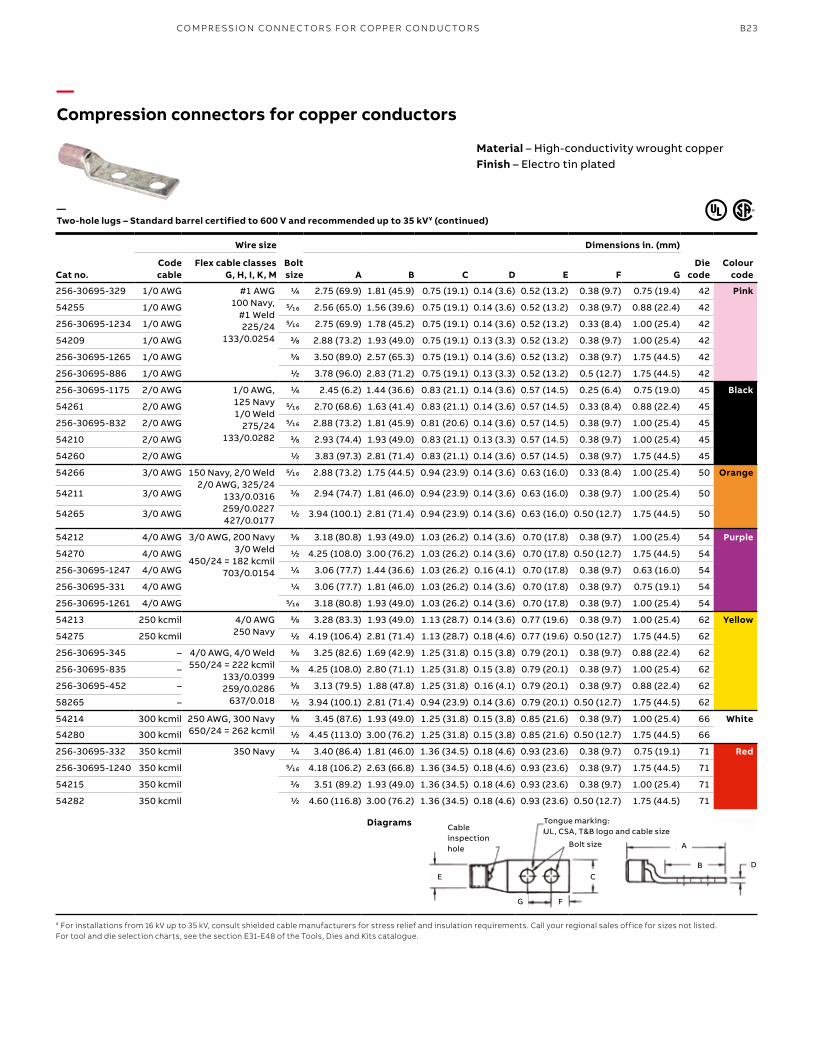
—Compression connectors for copper conductors
Cat no.
Wire size
Bolt size
Dimensions in. (mm)
Die code
Colour code
Code cable
Flex cable classes G, H, I, K, M A B C D E F G
256-30695-329 1/0 AWG #1 AWG100 Navy,
#1 Weld225/24
133/0.0254
1/4 2.75 (69.9) 1.81 (45.9) 0.75 (19.1) 0.14 (3.6) 0.52 (13.2) 0.38 (9.7) 0.75 (19.4) 42 Pink
54255 1/0 AWG 5⁄16 2.56 (65.0) 1.56 (39.6) 0.75 (19.1) 0.14 (3.6) 0.52 (13.2) 0.38 (9.7) 0.88 (22.4) 42
256-30695-1234 1/0 AWG 5⁄16 2.75 (69.9) 1.78 (45.2) 0.75 (19.1) 0.14 (3.6) 0.52 (13.2) 0.33 (8.4) 1.00 (25.4) 42
54209 1/0 AWG 3/8 2.88 (73.2) 1.93 (49.0) 0.75 (19.1) 0.13 (3.3) 0.52 (13.2) 0.38 (9.7) 1.00 (25.4) 42
256-30695-1265 1/0 AWG 3/8 3.50 (89.0) 2.57 (65.3) 0.75 (19.1) 0.14 (3.6) 0.52 (13.2) 0.38 (9.7) 1.75 (44.5) 42
256-30695-886 1/0 AWG 1/2 3.78 (96.0) 2.83 (71.2) 0.75 (19.1) 0.13 (3.3) 0.52 (13.2) 0.5 (12.7) 1.75 (44.5) 42
256-30695-1175 2/0 AWG 1/0 AWG, 125 Navy1/0 Weld
275/24133/0.0282
1/4 2.45 (6.2) 1.44 (36.6) 0.83 (21.1) 0.14 (3.6) 0.57 (14.5) 0.25 (6.4) 0.75 (19.0) 45 Black
54261 2/0 AWG 5⁄16 2.70 (68.6) 1.63 (41.4) 0.83 (21.1) 0.14 (3.6) 0.57 (14.5) 0.33 (8.4) 0.88 (22.4) 45
256-30695-832 2/0 AWG 5⁄16 2.88 (73.2) 1.81 (45.9) 0.81 (20.6) 0.14 (3.6) 0.57 (14.5) 0.38 (9.7) 1.00 (25.4) 45
54210 2/0 AWG 3/8 2.93 (74.4) 1.93 (49.0) 0.83 (21.1) 0.13 (3.3) 0.57 (14.5) 0.38 (9.7) 1.00 (25.4) 45
54260 2/0 AWG 1/2 3.83 (97.3) 2.81 (71.4) 0.83 (21.1) 0.14 (3.6) 0.57 (14.5) 0.38 (9.7) 1.75 (44.5) 45
54266 3/0 AWG 150 Navy, 2/0 Weld2/0 AWG, 325/24
133/0.0316259/0.0227427/0.0177
5⁄16 2.88 (73.2) 1.75 (44.5) 0.94 (23.9) 0.14 (3.6) 0.63 (16.0) 0.33 (8.4) 1.00 (25.4) 50 Orange
54211 3/0 AWG 3/8 2.94 (74.7) 1.81 (46.0) 0.94 (23.9) 0.14 (3.6) 0.63 (16.0) 0.38 (9.7) 1.00 (25.4) 50
54265 3/0 AWG 1/2 3.94 (100.1) 2.81 (71.4) 0.94 (23.9) 0.14 (3.6) 0.63 (16.0) 0.50 (12.7) 1.75 (44.5) 50
54212 4/0 AWG 3/0 AWG, 200 Navy3/0 Weld
450/24 = 182 kcmil703/0.0154
3/8 3.18 (80.8) 1.93 (49.0) 1.03 (26.2) 0.14 (3.6) 0.70 (17.8) 0.38 (9.7) 1.00 (25.4) 54 Purple
54270 4/0 AWG 1/2 4.25 (108.0) 3.00 (76.2) 1.03 (26.2) 0.14 (3.6) 0.70 (17.8) 0.50 (12.7) 1.75 (44.5) 54
256-30695-1247 4/0 AWG 1/4 3.06 (77.7) 1.44 (36.6) 1.03 (26.2) 0.16 (4.1) 0.70 (17.8) 0.38 (9.7) 0.63 (16.0) 54
256-30695-331 4/0 AWG 1/4 3.06 (77.7) 1.81 (46.0) 1.03 (26.2) 0.14 (3.6) 0.70 (17.8) 0.38 (9.7) 0.75 (19.1) 54
256-30695-1261 4/0 AWG 5⁄16 3.18 (80.8) 1.93 (49.0) 1.03 (26.2) 0.14 (3.6) 0.70 (17.8) 0.38 (9.7) 1.00 (25.4) 54
54213 250 kcmil 4/0 AWG250 Navy
3/8 3.28 (83.3) 1.93 (49.0) 1.13 (28.7) 0.14 (3.6) 0.77 (19.6) 0.38 (9.7) 1.00 (25.4) 62 Yellow
54275 250 kcmil 1/2 4.19 (106.4) 2.81 (71.4) 1.13 (28.7) 0.18 (4.6) 0.77 (19.6) 0.50 (12.7) 1.75 (44.5) 62
256-30695-345 – 4/0 AWG, 4/0 Weld550/24 = 222 kcmil
133/0.0399259/0.0286
637/0.018
3/8 3.25 (82.6) 1.69 (42.9) 1.25 (31.8) 0.15 (3.8) 0.79 (20.1) 0.38 (9.7) 0.88 (22.4) 62
256-30695-835 – 3/8 4.25 (108.0) 2.80 (71.1) 1.25 (31.8) 0.15 (3.8) 0.79 (20.1) 0.38 (9.7) 1.00 (25.4) 62
256-30695-452 – 3/8 3.13 (79.5) 1.88 (47.8) 1.25 (31.8) 0.16 (4.1) 0.79 (20.1) 0.38 (9.7) 0.88 (22.4) 62
58265 – 1/2 3.94 (100.1) 2.81 (71.4) 0.94 (23.9) 0.14 (3.6) 0.79 (20.1) 0.50 (12.7) 1.75 (44.5) 62
54214 300 kcmil 250 AWG, 300 Navy650/24 = 262 kcmil
3/8 3.45 (87.6) 1.93 (49.0) 1.25 (31.8) 0.15 (3.8) 0.85 (21.6) 0.38 (9.7) 1.00 (25.4) 66 White
54280 300 kcmil 1/2 4.45 (113.0) 3.00 (76.2) 1.25 (31.8) 0.15 (3.8) 0.85 (21.6) 0.50 (12.7) 1.75 (44.5) 66
256-30695-332 350 kcmil 350 Navy 1/4 3.40 (86.4) 1.81 (46.0) 1.36 (34.5) 0.18 (4.6) 0.93 (23.6) 0.38 (9.7) 0.75 (19.1) 71 Red
256-30695-1240 350 kcmil 5⁄16 4.18 (106.2) 2.63 (66.8) 1.36 (34.5) 0.18 (4.6) 0.93 (23.6) 0.38 (9.7) 1.75 (44.5) 71
54215 350 kcmil 3/8 3.51 (89.2) 1.93 (49.0) 1.36 (34.5) 0.18 (4.6) 0.93 (23.6) 0.38 (9.7) 1.00 (25.4) 71
54282 350 kcmil 1/2 4.60 (116.8) 3.00 (76.2) 1.36 (34.5) 0.18 (4.6) 0.93 (23.6) 0.50 (12.7) 1.75 (44.5) 71
—Two-hole lugs – Standard barrel certified to 600 V and recommended up to 35 kV¥ (continued)
¥ For installations from 16 kV up to 35 kV, consult shielded cable manufacturers for stress relief and insulation requirements. Call your regional sales office for sizes not listed.For tool and die selection charts, see the section E31-E48 of the Tools, Dies and Kits catalogue.
Diagrams
Material – High-conductivity wrought copperFinish – Electro tin plated
E
F
Cable inspection hole Bolt size
Tongue marking: UL, CSA, T&B logo and cable size
G
DB
A
C
CO M PR E SSI O N CO N N EC TO R S FO R CO PPER CO N D U C TO R S
B24 CO LO R- K E Y E D CO M PR E SSI O N CO N N EC TO R S Y S TEMS
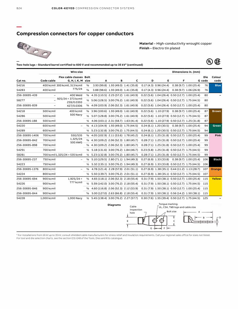
—Compression connectors for copper conductors
Cat no.
Wire size
Bolt size
Dimensions in. (mm)
Die code
Colour codeCode cable
Flex cable classes G, H, I, K, M A B C D E F G
54216 400 kcmil 300 kcmil, 313 kcmil775/24
3/8 3.93 (99.8) 1.93 (49.0) 1.41 (35.8) 0.17 (4.3) 0.96 (24.4) 0.38 (9.7) 1.00 (25.4) 76 Blue
54283 400 kcmil 3/8 3.88 (98.6) 1.93 (49.0) 1.41 (35.8) 0.17 (4.3) 0.96 (24.4) 0.38 (9.7) 1.06 (26.9) 76
256-30695-439 – 400 Weld925/24 = 373 kcmil
259/0.0393427/0.0306
3/8 4.35 (110.5) 2.25 (57.2) 1.61 (40.9) 0.22 (5.6) 1.04 (26.4) 0.50 (12.7) 1.00 (25.4) 80 –
58277 – 1/2 5.06 (128.5) 3.00 (76.2) 1.61 (40.9) 0.22 (5.6) 1.04 (26.4) 0.50 (12.7) 1.75 (44.5) 80
256-30695-839 – 3/8 4.09 (103.9) 2.06 (52.3) 1.61 (40.9) 0.22 (5.6) 1.04 (26.4) 0.50 (12.7) 1.00 (25.4) 80
54218 500 kcmil 400 kcmil500 Navy
3/8 3.96 (100.6) 1.93 (49.0) 1.61 (40.9) 0.22 (5.6) 1.10 (27.9) 0.38 (9.7) 1.00 (25.4) 87 Brown
54286 500 kcmil 1/2 5.07 (128.8) 3.00 (76.2) 1.61 (40.9) 0.22 (5.6) 1.10 (27.9) 0.50 (12.7) 1.75 (44.5) 87
256-30695-188 500 kcmil 1/2 4.06 (103.1) 2.31 (58.7) 1.63 (41.4) 0.22 (5.6) 1.10 (27.9) 0.50 (12.7) 1.25 (31.8) 87
54220 600 kcmil – 3/8 4.13 (104.9) 1.93 (49.0) 1.75 (44.5) 0.24 (6.1) 1.20 (30.5) 0.38 (9.7) 1.00 (25.4) 94 Green
54289 600 kcmil 1/2 5.23 (132.8) 3.00 (76.2) 1.75 (44.5) 0.24 (6.1) 1.20 (30.5) 0.50 (12.7) 1.75 (44.5) 94
256-30695-1406 700 kcmil 550/5351,325/24500 AWG
3/8 4.05 (102.9) 2.11 (53.6) 1.78 (45.2) 0.24 (6.1) 1.25 (31.8) 0.50 (12.7) 1.00 (25.4) 99 Pink
256-30695-842 700 kcmil 3/8 4.30 (109.2) 2.06 (52.3) 1.80 (45.7) 0.28 (7.1) 1.25 (31.8) 0.50 (12.7) 1.00 (25.4) 99
256-30695-898 700 kcmil 3/8 4.30 (109.2) 2.06 (52.3) 1.80 (45.7) 0.28 (7.1) 1.25 (31.8) 0.50 (12.7) 1.00 (25.4) 99
54291 700 kcmil 1/2 5.18 (131.6) 3.00 (76.2) 1.84 (46.7) 0.23 (5.8) 1.25 (31.8) 0.50 (12.7) 1.75 (44.5) 99
58281 700 kcmil1,325/24 = 535 kcmil 1/2 5.23 (132.8) 3.00 (76.2) 1.80 (45.7) 0.28 (7.1) 1.25 (31.8) 0.50 (12.7) 1.75 (44.5) 99
256-30695-237 750 kcmil – 3/8 5.10 (129.5) 2.80 (71.1) 1.94 (49.3) 0.27 (6.9) 1.33 (33.8) 0.38 (9.7) 1.00 (25.4) 106 Black
54223 750 kcmil 1/2 5.32 (135.1) 3.00 (76.2) 1.94 (49.3) 0.27 (6.9) 1.33 (33.8) 0.50 (12.7) 1.75 (44.5) 106
256-30695-1376 800 kcmil – 3/8 4.78 (121.4) 2.28 (57.9) 2.01 (51.1) 0.27 (6.9) 1.38 (35.1) 0.44 (11.2) 1.13 (28.7) 107 Orange
54224 800 kcmil 1/2 5.50 (139.7) 3.00 (76.2) 2.01 (51.1) 0.27 (6.9) 1.38 (35.1) 0.50 (12.7) 1.75 (44.5) 107
256-30695-694 900 kcmil 1,925/24 = 777 kcmil
3/8 4.65 (118.1) 2.06 (52.3) 2.18 (55.4) 0.31 (7.9) 1.50 (38.1) 0.50 (12.7) 1.00 (25.4) 115 Yellow
54226 900 kcmil 1/2 5.59 (142.0) 3.00 (76.2) 2.18 (55.4) 0.31 (7.9) 1.50 (38.1) 0.50 (12.7) 1.75 (44.5) 115
256-30695-846 900 kcmil 3/8 4.60 (116.8) 2.06 (52.3) 2.12 (53.9) 0.31 (7.9) 1.50 (38.1) 0.50 (12.7) 1.00 (25.4) 115
256-30695-844 900 kcmil 5/8 5.00 (127.0) 2.63 (66.8) 2.18 (55.4) 0.31 (7.9) 1.50 (38.1) 0.56 (14.2) 1.50 (38.1) 115
54228 1,000 kcmil 1,000 Navy 1/2 5.45 (138.4) 3.00 (76.2) 2.27 (57.7) 0.30 (7.6) 1.55 (39.4) 0.50 (12.7) 1.75 (44.5) 125 –
¥ For installations from 16 kV up to 35 kV, consult shielded cable manufacturers for stress relief and insulation requirements. Call your regional sales office for sizes not listed.For tool and die selection charts, see the section E31-E48 of the Tools, Dies and Kits catalogue.
Diagrams
—Two-hole lugs – Standard barrel certified to 600 V and recommended up to 35 kV¥ (continued)
Material – High-conductivity wrought copperFinish – Electro tin plated
E
F
Cable inspection hole Bolt size
Tongue marking: UL, CSA, T&B logo and cable size
G
DB
A
C
B25
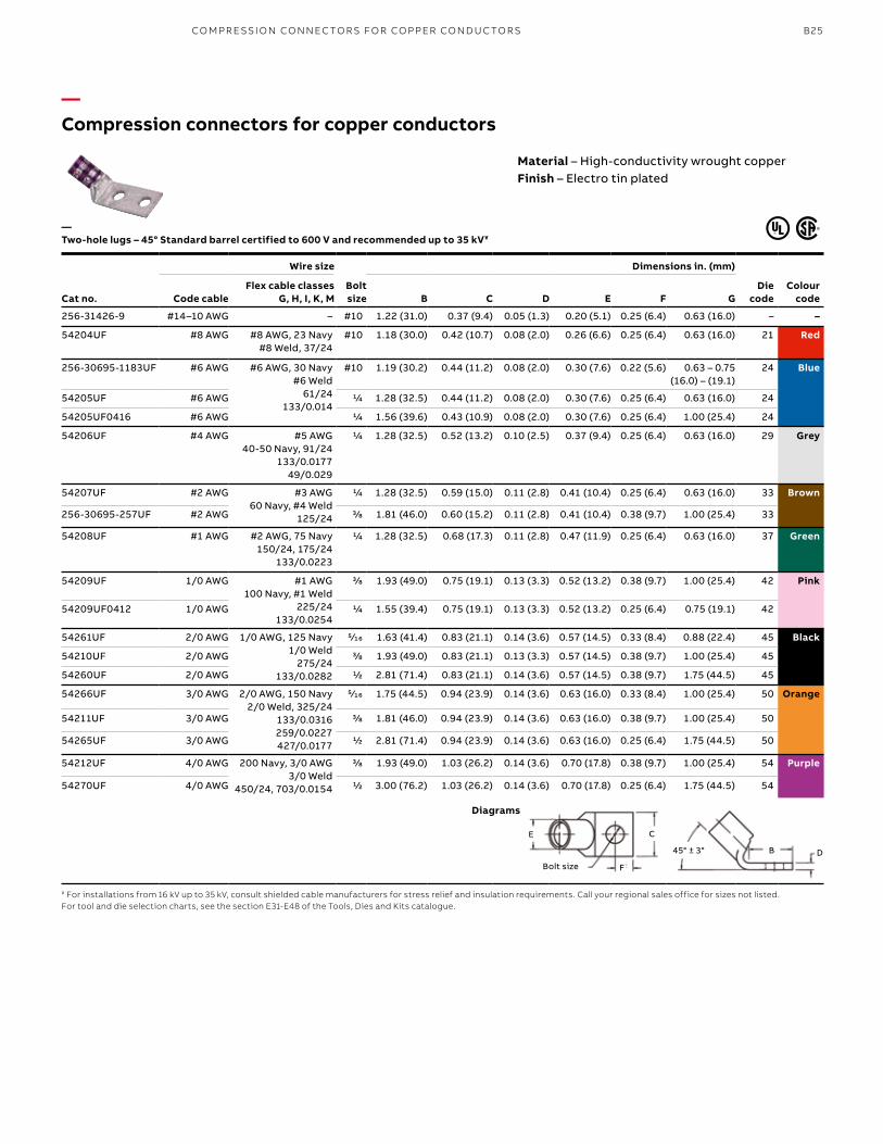
—Compression connectors for copper conductors
Material – High-conductivity wrought copperFinish – Electro tin plated
Cat no.
Wire size
Bolt size
Dimensions in. (mm)
Die code
Colour codeCode cable
Flex cable classes G, H, I, K, M B C D E F G
256-31426-9 #14–10 AWG – #10 1.22 (31.0) 0.37 (9.4) 0.05 (1.3) 0.20 (5.1) 0.25 (6.4) 0.63 (16.0) – –
54204UF #8 AWG #8 AWG, 23 Navy#8 Weld, 37/24
#10 1.18 (30.0) 0.42 (10.7) 0.08 (2.0) 0.26 (6.6) 0.25 (6.4) 0.63 (16.0) 21 Red
256-30695-1183UF #6 AWG #6 AWG, 30 Navy#6 Weld
61/24133/0.014
#10 1.19 (30.2) 0.44 (11.2) 0.08 (2.0) 0.30 (7.6) 0.22 (5.6) 0.63 – 0.75 (16.0) – (19.1)
24 Blue
54205UF #6 AWG 1/4 1.28 (32.5) 0.44 (11.2) 0.08 (2.0) 0.30 (7.6) 0.25 (6.4) 0.63 (16.0) 24
54205UF0416 #6 AWG 1/4 1.56 (39.6) 0.43 (10.9) 0.08 (2.0) 0.30 (7.6) 0.25 (6.4) 1.00 (25.4) 24
54206UF #4 AWG #5 AWG40-50 Navy, 91/24
133/0.017749/0.029
1/4 1.28 (32.5) 0.52 (13.2) 0.10 (2.5) 0.37 (9.4) 0.25 (6.4) 0.63 (16.0) 29 Grey
54207UF #2 AWG #3 AWG60 Navy, #4 Weld
125/24
1/4 1.28 (32.5) 0.59 (15.0) 0.11 (2.8) 0.41 (10.4) 0.25 (6.4) 0.63 (16.0) 33 Brown
256-30695-257UF #2 AWG 3/8 1.81 (46.0) 0.60 (15.2) 0.11 (2.8) 0.41 (10.4) 0.38 (9.7) 1.00 (25.4) 33
54208UF #1 AWG #2 AWG, 75 Navy150/24, 175/24
133/0.0223
1/4 1.28 (32.5) 0.68 (17.3) 0.11 (2.8) 0.47 (11.9) 0.25 (6.4) 0.63 (16.0) 37 Green
54209UF 1/0 AWG #1 AWG100 Navy, #1 Weld
225/24133/0.0254
3/8 1.93 (49.0) 0.75 (19.1) 0.13 (3.3) 0.52 (13.2) 0.38 (9.7) 1.00 (25.4) 42 Pink
54209UF0412 1/0 AWG 1/4 1.55 (39.4) 0.75 (19.1) 0.13 (3.3) 0.52 (13.2) 0.25 (6.4) 0.75 (19.1) 42
54261UF 2/0 AWG 1/0 AWG, 125 Navy1/0 Weld
275/24133/0.0282
5⁄16 1.63 (41.4) 0.83 (21.1) 0.14 (3.6) 0.57 (14.5) 0.33 (8.4) 0.88 (22.4) 45 Black
54210UF 2/0 AWG 3/8 1.93 (49.0) 0.83 (21.1) 0.13 (3.3) 0.57 (14.5) 0.38 (9.7) 1.00 (25.4) 45
54260UF 2/0 AWG 1/2 2.81 (71.4) 0.83 (21.1) 0.14 (3.6) 0.57 (14.5) 0.38 (9.7) 1.75 (44.5) 45
54266UF 3/0 AWG 2/0 AWG, 150 Navy2/0 Weld, 325/24
133/0.0316259/0.0227427/0.0177
5⁄16 1.75 (44.5) 0.94 (23.9) 0.14 (3.6) 0.63 (16.0) 0.33 (8.4) 1.00 (25.4) 50 Orange
54211UF 3/0 AWG 3/8 1.81 (46.0) 0.94 (23.9) 0.14 (3.6) 0.63 (16.0) 0.38 (9.7) 1.00 (25.4) 50
54265UF 3/0 AWG 1/2 2.81 (71.4) 0.94 (23.9) 0.14 (3.6) 0.63 (16.0) 0.25 (6.4) 1.75 (44.5) 50
54212UF 4/0 AWG 200 Navy, 3/0 AWG3/0 Weld
450/24, 703/0.0154
3/8 1.93 (49.0) 1.03 (26.2) 0.14 (3.6) 0.70 (17.8) 0.38 (9.7) 1.00 (25.4) 54 Purple
54270UF 4/0 AWG 1/2 3.00 (76.2) 1.03 (26.2) 0.14 (3.6) 0.70 (17.8) 0.25 (6.4) 1.75 (44.5) 54
—Two-hole lugs – 45° Standard barrel certified to 600 V and recommended up to 35 kV¥
¥ For installations from 16 kV up to 35 kV, consult shielded cable manufacturers for stress relief and insulation requirements. Call your regional sales office for sizes not listed.For tool and die selection charts, see the section E31-E48 of the Tools, Dies and Kits catalogue.
Diagrams
E C
F
DB 45° ± 3°
Bolt size
CO M PR E SSI O N CO N N EC TO R S FO R CO PPER CO N D U C TO R S
B26 CO LO R- K E Y E D CO M PR E SSI O N CO N N EC TO R S Y S TEMS
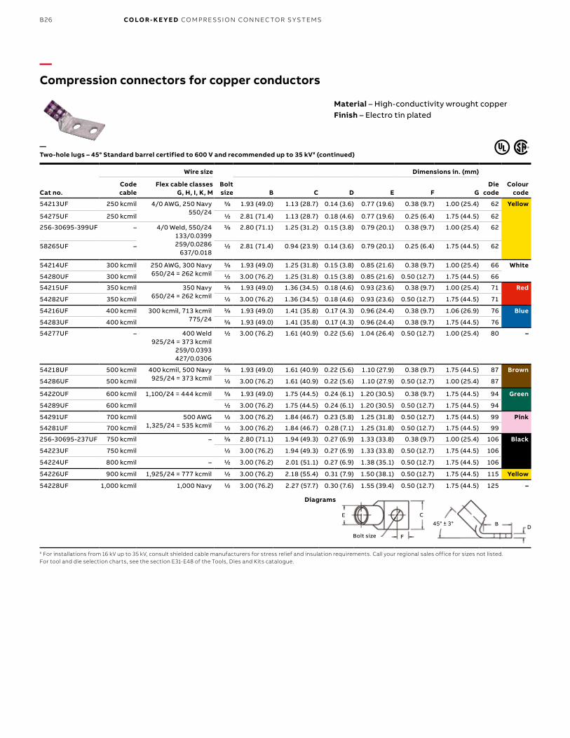
—Compression connectors for copper conductors
Cat no.
Wire size
Bolt size
Dimensions in. (mm)
Die code
Colour code
Code cable
Flex cable classes G, H, I, K, M B C D E F G
54213UF 250 kcmil 4/0 AWG, 250 Navy550/24
3/8 1.93 (49.0) 1.13 (28.7) 0.14 (3.6) 0.77 (19.6) 0.38 (9.7) 1.00 (25.4) 62 Yellow
54275UF 250 kcmil 1/2 2.81 (71.4) 1.13 (28.7) 0.18 (4.6) 0.77 (19.6) 0.25 (6.4) 1.75 (44.5) 62
256-30695-399UF – 4/0 Weld, 550/24133/0.0399259/0.0286
637/0.018
3/8 2.80 (71.1) 1.25 (31.2) 0.15 (3.8) 0.79 (20.1) 0.38 (9.7) 1.00 (25.4) 62
58265UF – 1/2 2.81 (71.4) 0.94 (23.9) 0.14 (3.6) 0.79 (20.1) 0.25 (6.4) 1.75 (44.5) 62
54214UF 300 kcmil 250 AWG, 300 Navy650/24 = 262 kcmil
3/8 1.93 (49.0) 1.25 (31.8) 0.15 (3.8) 0.85 (21.6) 0.38 (9.7) 1.00 (25.4) 66 White
54280UF 300 kcmil 1/2 3.00 (76.2) 1.25 (31.8) 0.15 (3.8) 0.85 (21.6) 0.50 (12.7) 1.75 (44.5) 66
54215UF 350 kcmil 350 Navy650/24 = 262 kcmil
3/8 1.93 (49.0) 1.36 (34.5) 0.18 (4.6) 0.93 (23.6) 0.38 (9.7) 1.00 (25.4) 71 Red
54282UF 350 kcmil 1/2 3.00 (76.2) 1.36 (34.5) 0.18 (4.6) 0.93 (23.6) 0.50 (12.7) 1.75 (44.5) 71
54216UF 400 kcmil 300 kcmil, 713 kcmil775/24
3/8 1.93 (49.0) 1.41 (35.8) 0.17 (4.3) 0.96 (24.4) 0.38 (9.7) 1.06 (26.9) 76 Blue
54283UF 400 kcmil 3/8 1.93 (49.0) 1.41 (35.8) 0.17 (4.3) 0.96 (24.4) 0.38 (9.7) 1.75 (44.5) 76
54277UF – 400 Weld925/24 = 373 kcmil
259/0.0393427/0.0306
1/2 3.00 (76.2) 1.61 (40.9) 0.22 (5.6) 1.04 (26.4) 0.50 (12.7) 1.00 (25.4) 80 –
54218UF 500 kcmil 400 kcmil, 500 Navy925/24 = 373 kcmil
3/8 1.93 (49.0) 1.61 (40.9) 0.22 (5.6) 1.10 (27.9) 0.38 (9.7) 1.75 (44.5) 87 Brown
54286UF 500 kcmil 1/2 3.00 (76.2) 1.61 (40.9) 0.22 (5.6) 1.10 (27.9) 0.50 (12.7) 1.00 (25.4) 87
54220UF 600 kcmil 1,100/24 = 444 kcmil 3/8 1.93 (49.0) 1.75 (44.5) 0.24 (6.1) 1.20 (30.5) 0.38 (9.7) 1.75 (44.5) 94 Green
54289UF 600 kcmil 1/2 3.00 (76.2) 1.75 (44.5) 0.24 (6.1) 1.20 (30.5) 0.50 (12.7) 1.75 (44.5) 94
54291UF 700 kcmil 500 AWG1,325/24 = 535 kcmil
1/2 3.00 (76.2) 1.84 (46.7) 0.23 (5.8) 1.25 (31.8) 0.50 (12.7) 1.75 (44.5) 99 Pink
54281UF 700 kcmil 1/2 3.00 (76.2) 1.84 (46.7) 0.28 (7.1) 1.25 (31.8) 0.50 (12.7) 1.75 (44.5) 99
256-30695-237UF 750 kcmil – 3/8 2.80 (71.1) 1.94 (49.3) 0.27 (6.9) 1.33 (33.8) 0.38 (9.7) 1.00 (25.4) 106 Black
54223UF 750 kcmil 1/2 3.00 (76.2) 1.94 (49.3) 0.27 (6.9) 1.33 (33.8) 0.50 (12.7) 1.75 (44.5) 106
54224UF 800 kcmil – 1/2 3.00 (76.2) 2.01 (51.1) 0.27 (6.9) 1.38 (35.1) 0.50 (12.7) 1.75 (44.5) 106
54226UF 900 kcmil 1,925/24 = 777 kcmil 1/2 3.00 (76.2) 2.18 (55.4) 0.31 (7.9) 1.50 (38.1) 0.50 (12.7) 1.75 (44.5) 115 Yellow
54228UF 1,000 kcmil 1,000 Navy 1/2 3.00 (76.2) 2.27 (57.7) 0.30 (7.6) 1.55 (39.4) 0.50 (12.7) 1.75 (44.5) 125 –
—Two-hole lugs – 45° Standard barrel certified to 600 V and recommended up to 35 kV¥ (continued)
¥ For installations from 16 kV up to 35 kV, consult shielded cable manufacturers for stress relief and insulation requirements. Call your regional sales office for sizes not listed.For tool and die selection charts, see the section E31-E48 of the Tools, Dies and Kits catalogue.
Diagrams
Material – High-conductivity wrought copperFinish – Electro tin plated
E C
F
DB 45° ± 3°
Bolt size
B27
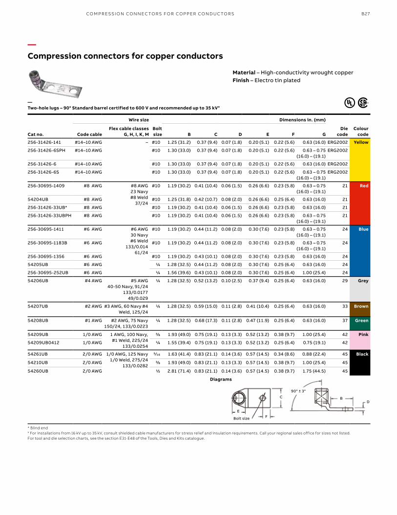
—Compression connectors for copper conductors
Cat no.
Wire size
Bolt size
Dimensions in. (mm)
Die code
Colour codeCode cable
Flex cable classes G, H, I, K, M B C D E F G
256-31426-141 #14–10 AWG – #10 1.25 (31.2) 0.37 (9.4) 0.07 (1.8) 0.20 (5.1) 0.22 (5.6) 0.63 (16.0) ERG2002 Yellow
256-31426-6SPH #14–10 AWG #10 1.30 (33.0) 0.37 (9.4) 0.07 (1.8) 0.20 (5.1) 0.22 (5.6) 0.63 – 0.75 (16.0) – (19.1)
ERG2002
256-31426-6 #14–10 AWG #10 1.30 (33.0) 0.37 (9.4) 0.07 (1.8) 0.20 (5.1) 0.22 (5.6) 0.63 (16.0) ERG2002
256-31426-6S #14–10 AWG #10 1.30 (33.0) 0.37 (9.4) 0.07 (1.8) 0.20 (5.1) 0.22 (5.6) 0.63 – 0.75 (16.0) – (19.1)
ERG2002
256-30695-1409 #8 AWG #8 AWG23 Navy#8 Weld
37/24
#10 1.19 (30.2) 0.41 (10.4) 0.06 (1.5) 0.26 (6.6) 0.23 (5.8) 0.63 – 0.75 (16.0) – (19.1)
21 Red
54204UB #8 AWG #10 1.25 (31.8) 0.42 (10.7) 0.08 (2.0) 0.26 (6.6) 0.25 (6.4) 0.63 (16.0) 21
256-31426-33UB* #8 AWG #10 1.19 (30.2) 0.41 (10.4) 0.06 (1.5) 0.26 (6.6) 0.23 (5.8) 0.63 (16.0) 21
256-31426-33UBPH #8 AWG #10 1.19 (30.2) 0.41 (10.4) 0.06 (1.5) 0.26 (6.6) 0.23 (5.8) 0.63 – 0.75 (16.0) – (19.1)
21
256-30695-1411 #6 AWG #6 AWG 30 Navy#6 Weld
133/0.01461/24
#10 1.19 (30.2) 0.44 (11.2) 0.08 (2.0) 0.30 (7.6) 0.23 (5.8) 0.63 – 0.75 (16.0) – (19.1)
24 Blue
256-30695-1183B #6 AWG #10 1.19 (30.2) 0.44 (11.2) 0.08 (2.0) 0.30 (7.6) 0.23 (5.8) 0.63 – 0.75 (16.0) – (19.1)
24
256-30695-1356 #6 AWG #10 1.19 (30.2) 0.43 (10.1) 0.08 (2.0) 0.30 (7.6) 0.23 (5.8) 0.63 (16.0) 24
54205UB #6 AWG 1/4 1.28 (32.5) 0.44 (11.2) 0.08 (2.0) 0.30 (7.6) 0.25 (6.4) 0.63 (16.0) 24
256-30695-252UB #6 AWG 1/4 1.56 (39.6) 0.43 (10.1) 0.08 (2.0) 0.30 (7.6) 0.25 (6.4) 1.00 (25.4) 24
54206UB #4 AWG #5 AWG 40-50 Navy, 91/24
133/0.017749/0.029
1/4 1.28 (32.5) 0.52 (13.2) 0.10 (2.5) 0.37 (9.4) 0.25 (6.4) 0.63 (16.0) 29 Grey
54207UB #2 AWG #3 AWG, 60 Navy #4 Weld, 125/24
1/4 1.28 (32.5) 0.59 (15.0) 0.11 (2.8) 0.41 (10.4) 0.25 (6.4) 0.63 (16.0) 33 Brown
54208UB #1 AWG #2 AWG, 75 Navy150/24, 133/0.0223
1/4 1.28 (32.5) 0.68 (17.3) 0.11 (2.8) 0.47 (11.9) 0.25 (6.4) 0.63 (16.0) 37 Green
54209UB 1/0 AWG 1 AWG, 100 Navy,#1 Weld, 225/24
133/0.0254
3/8 1.93 (49.0) 0.75 (19.1) 0.13 (3.3) 0.52 (13.2) 0.38 (9.7) 1.00 (25.4) 42 Pink
54209UB0412 1/0 AWG 1/4 1.55 (39.4) 0.75 (19.1) 0.13 (3.3) 0.52 (13.2) 0.25 (6.4) 0.75 (19.1) 42
54261UB 2/0 AWG 1/0 AWG, 125 Navy1/0 Weld, 275/24
133/0.0282
5⁄16 1.63 (41.4) 0.83 (21.1) 0.14 (3.6) 0.57 (14.5) 0.34 (8.6) 0.88 (22.4) 45 Black
54210UB 2/0 AWG 3/8 1.93 (49.0) 0.83 (21.1) 0.13 (3.3) 0.57 (14.5) 0.38 (9.7) 1.00 (25.4) 45
54260UB 2/0 AWG 1/2 2.81 (71.4) 0.83 (21.1) 0.14 (3.6) 0.57 (14.5) 0.38 (9.7) 1.75 (44.5) 45
—Two-hole lugs – 90° Standard barrel certified to 600 V and recommended up to 35 kV¥
* Blind end¥ For installations from 16 kV up to 35 kV, consult shielded cable manufacturers for stress relief and insulation requirements. Call your regional sales office for sizes not listed.For tool and die selection charts, see the section E31-E48 of the Tools, Dies and Kits catalogue.
Diagrams
Material – High-conductivity wrought copperFinish – Electro tin plated
EF
DB
90° ± 3°
Bolt size
C
CO M PR E SSI O N CO N N EC TO R S FO R CO PPER CO N D U C TO R S
B28 CO LO R- K E Y E D CO M PR E SSI O N CO N N EC TO R S Y S TEMS
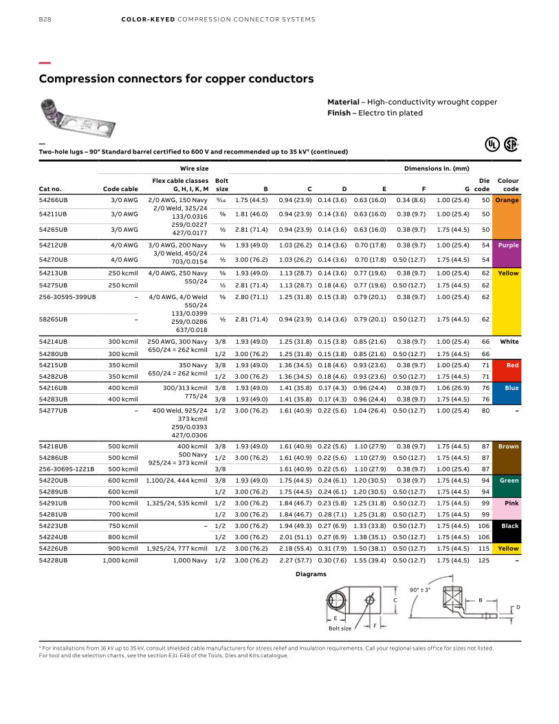
—Compression connectors for copper conductors
Cat no.
Wire size
Bolt size
Dimensions in. (mm)
Die code
Colour codeCode cable
Flex cable classes G, H, I, K, M B C D E F G
54266UB 3/0 AWG 2/0 AWG, 150 Navy2/0 Weld, 325/24
133/0.0316259/0.0227427/0.0177
5⁄16 1.75 (44.5) 0.94 (23.9) 0.14 (3.6) 0.63 (16.0) 0.34 (8.6) 1.00 (25.4) 50 Orange
54211UB 3/0 AWG 3/8 1.81 (46.0) 0.94 (23.9) 0.14 (3.6) 0.63 (16.0) 0.38 (9.7) 1.00 (25.4) 50
54265UB 3/0 AWG 1/2 2.81 (71.4) 0.94 (23.9) 0.14 (3.6) 0.63 (16.0) 0.38 (9.7) 1.75 (44.5) 50
54212UB 4/0 AWG 3/0 AWG, 200 Navy3/0 Weld, 450/24
703/0.0154
3/8 1.93 (49.0) 1.03 (26.2) 0.14 (3.6) 0.70 (17.8) 0.38 (9.7) 1.00 (25.4) 54 Purple
54270UB 4/0 AWG 1/2 3.00 (76.2) 1.03 (26.2) 0.14 (3.6) 0.70 (17.8) 0.50 (12.7) 1.75 (44.5) 54
54213UB 250 kcmil 4/0 AWG, 250 Navy550/24
3/8 1.93 (49.0) 1.13 (28.7) 0.14 (3.6) 0.77 (19.6) 0.38 (9.7) 1.00 (25.4) 62 Yellow
54275UB 250 kcmil 1/2 2.81 (71.4) 1.13 (28.7) 0.18 (4.6) 0.77 (19.6) 0.50 (12.7) 1.75 (44.5) 62
256-30595-399UB – 4/0 AWG, 4/0 Weld550/24
133/0.0399259/0.0286
637/0.018
3/8 2.80 (71.1) 1.25 (31.8) 0.15 (3.8) 0.79 (20.1) 0.38 (9.7) 1.00 (25.4) 62
58265UB – 1/2 2.81 (71.4) 0.94 (23.9) 0.14 (3.6) 0.79 (20.1) 0.50 (12.7) 1.75 (44.5) 62
54214UB 300 kcmil 250 AWG, 300 Navy650/24 = 262 kcmil
3/8 1.93 (49.0) 1.25 (31.8) 0.15 (3.8) 0.85 (21.6) 0.38 (9.7) 1.00 (25.4) 66 White
54280UB 300 kcmil 1/2 3.00 (76.2) 1.25 (31.8) 0.15 (3.8) 0.85 (21.6) 0.50 (12.7) 1.75 (44.5) 66
54215UB 350 kcmil 350 Navy650/24 = 262 kcmil
3/8 1.93 (49.0) 1.36 (34.5) 0.18 (4.6) 0.93 (23.6) 0.38 (9.7) 1.00 (25.4) 71 Red
54282UB 350 kcmil 1/2 3.00 (76.2) 1.36 (34.5) 0.18 (4.6) 0.93 (23.6) 0.50 (12.7) 1.75 (44.5) 71
54216UB 400 kcmil 300/313 kcmil775/24
3/8 1.93 (49.0) 1.41 (35.8) 0.17 (4.3) 0.96 (24.4) 0.38 (9.7) 1.06 (26.9) 76 Blue
54283UB 400 kcmil 3/8 1.93 (49.0) 1.41 (35.8) 0.17 (4.3) 0.96 (24.4) 0.38 (9.7) 1.75 (44.5) 76
54277UB – 400 Weld, 925/24373 kcmil
259/0.0393427/0.0306
1/2 3.00 (76.2) 1.61 (40.9) 0.22 (5.6) 1.04 (26.4) 0.50 (12.7) 1.00 (25.4) 80 –
54218UB 500 kcmil 400 kcmil500 Navy
925/24 = 373 kcmil
3/8 1.93 (49.0) 1.61 (40.9) 0.22 (5.6) 1.10 (27.9) 0.38 (9.7) 1.75 (44.5) 87 Brown
54286UB 500 kcmil 1/2 3.00 (76.2) 1.61 (40.9) 0.22 (5.6) 1.10 (27.9) 0.50 (12.7) 1.75 (44.5) 87
256-30695-1221B 500 kcmil 3/8 1.61 (40.9) 0.22 (5.6) 1.10 (27.9) 0.38 (9.7) 1.00 (25.4) 87
54220UB 600 kcmil 1,100/24, 444 kcmil 3/8 1.93 (49.0) 1.75 (44.5) 0.24 (6.1) 1.20 (30.5) 0.38 (9.7) 1.75 (44.5) 94 Green
54289UB 600 kcmil 1/2 3.00 (76.2) 1.75 (44.5) 0.24 (6.1) 1.20 (30.5) 0.50 (12.7) 1.75 (44.5) 94
54291UB 700 kcmil 1,325/24, 535 kcmil 1/2 3.00 (76.2) 1.84 (46.7) 0.23 (5.8) 1.25 (31.8) 0.50 (12.7) 1.75 (44.5) 99 Pink
54281UB 700 kcmil 1/2 3.00 (76.2) 1.84 (46.7) 0.28 (7.1) 1.25 (31.8) 0.50 (12.7) 1.75 (44.5) 99
54223UB 750 kcmil – 1/2 3.00 (76.2) 1.94 (49.3) 0.27 (6.9) 1.33 (33.8) 0.50 (12.7) 1.75 (44.5) 106 Black
54224UB 800 kcmil 1/2 3.00 (76.2) 2.01 (51.1) 0.27 (6.9) 1.38 (35.1) 0.50 (12.7) 1.75 (44.5) 106
54226UB 900 kcmil 1,925/24, 777 kcmil 1/2 3.00 (76.2) 2.18 (55.4) 0.31 (7.9) 1.50 (38.1) 0.50 (12.7) 1.75 (44.5) 115 Yellow
54228UB 1,000 kcmil 1,000 Navy 1/2 3.00 (76.2) 2.27 (57.7) 0.30 (7.6) 1.55 (39.4) 0.50 (12.7) 1.75 (44.5) 125 –
—Two-hole lugs – 90° Standard barrel certified to 600 V and recommended up to 35 kV¥ (continued)
¥ For installations from 16 kV up to 35 kV, consult shielded cable manufacturers for stress relief and insulation requirements. Call your regional sales office for sizes not listed.For tool and die selection charts, see the section E31-E48 of the Tools, Dies and Kits catalogue.
Diagrams
Material – High-conductivity wrought copperFinish – Electro tin plated
EF
DB
90° ± 3°
Bolt size
C
B29
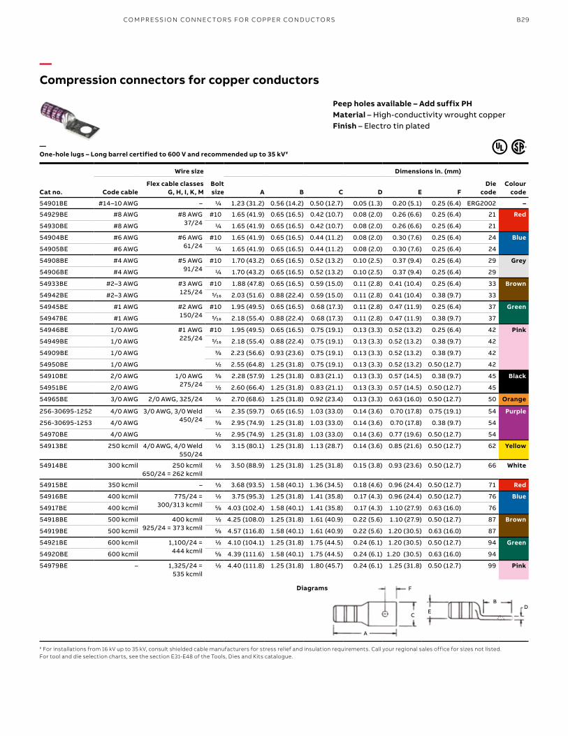
—Compression connectors for copper conductors
Cat no.
Wire size
Bolt size
Dimensions in. (mm)
Die code
Colour codeCode cable
Flex cable classes G, H, I, K, M A B C D E F
54901BE #14–10 AWG – 1/4 1.23 (31.2) 0.56 (14.2) 0.50 (12.7) 0.05 (1.3) 0.20 (5.1) 0.25 (6.4) ERG2002 –
54929BE #8 AWG #8 AWG37/24
#10 1.65 (41.9) 0.65 (16.5) 0.42 (10.7) 0.08 (2.0) 0.26 (6.6) 0.25 (6.4) 21 Red
54930BE #8 AWG 1/4 1.65 (41.9) 0.65 (16.5) 0.42 (10.7) 0.08 (2.0) 0.26 (6.6) 0.25 (6.4) 21
54904BE #6 AWG #6 AWG61/24
#10 1.65 (41.9) 0.65 (16.5) 0.44 (11.2) 0.08 (2.0) 0.30 (7.6) 0.25 (6.4) 24 Blue
54905BE #6 AWG 1/4 1.65 (41.9) 0.65 (16.5) 0.44 (11.2) 0.08 (2.0) 0.30 (7.6) 0.25 (6.4) 24
54908BE #4 AWG #5 AWG91/24
#10 1.70 (43.2) 0.65 (16.5) 0.52 (13.2) 0.10 (2.5) 0.37 (9.4) 0.25 (6.4) 29 Grey
54906BE #4 AWG 1/4 1.70 (43.2) 0.65 (16.5) 0.52 (13.2) 0.10 (2.5) 0.37 (9.4) 0.25 (6.4) 29
54933BE #2–3 AWG #3 AWG125/24
#10 1.88 (47.8) 0.65 (16.5) 0.59 (15.0) 0.11 (2.8) 0.41 (10.4) 0.25 (6.4) 33 Brown
54942BE #2–3 AWG 5⁄16 2.03 (51.6) 0.88 (22.4) 0.59 (15.0) 0.11 (2.8) 0.41 (10.4) 0.38 (9.7) 33
54945BE #1 AWG #2 AWG150/24
#10 1.95 (49.5) 0.65 (16.5) 0.68 (17.3) 0.11 (2.8) 0.47 (11.9) 0.25 (6.4) 37 Green
54947BE #1 AWG 5⁄16 2.18 (55.4) 0.88 (22.4) 0.68 (17.3) 0.11 (2.8) 0.47 (11.9) 0.38 (9.7) 37
54946BE 1/0 AWG #1 AWG225/24
#10 1.95 (49.5) 0.65 (16.5) 0.75 (19.1) 0.13 (3.3) 0.52 (13.2) 0.25 (6.4) 42 Pink
54949BE 1/0 AWG 5⁄16 2.18 (55.4) 0.88 (22.4) 0.75 (19.1) 0.13 (3.3) 0.52 (13.2) 0.38 (9.7) 42
54909BE 1/0 AWG 3/8 2.23 (56.6) 0.93 (23.6) 0.75 (19.1) 0.13 (3.3) 0.52 (13.2) 0.38 (9.7) 42
54950BE 1/0 AWG 1/2 2.55 (64.8) 1.25 (31.8) 0.75 (19.1) 0.13 (3.3) 0.52 (13.2) 0.50 (12.7) 42
54910BE 2/0 AWG 1/0 AWG275/24
3/8 2.28 (57.9) 1.25 (31.8) 0.83 (21.1) 0.13 (3.3) 0.57 (14.5) 0.38 (9.7) 45 Black
54951BE 2/0 AWG 1/2 2.60 (66.4) 1.25 (31.8) 0.83 (21.1) 0.13 (3.3) 0.57 (14.5) 0.50 (12.7) 45
54965BE 3/0 AWG 2/0 AWG, 325/24 1/2 2.70 (68.6) 1.25 (31.8) 0.92 (23.4) 0.13 (3.3) 0.63 (16.0) 0.50 (12.7) 50 Orange
256-30695-1252 4/0 AWG 3/0 AWG, 3/0 Weld450/24
1/4 2.35 (59.7) 0.65 (16.5) 1.03 (33.0) 0.14 (3.6) 0.70 (17.8) 0.75 (19.1) 54 Purple
256-30695-1253 4/0 AWG 3/8 2.95 (74.9) 1.25 (31.8) 1.03 (33.0) 0.14 (3.6) 0.70 (17.8) 0.38 (9.7) 54
54970BE 4/0 AWG 1/2 2.95 (74.9) 1.25 (31.8) 1.03 (33.0) 0.14 (3.6) 0.77 (19.6) 0.50 (12.7) 54
54913BE 250 kcmil 4/0 AWG, 4/0 Weld550/24
1/2 3.15 (80.1) 1.25 (31.8) 1.13 (28.7) 0.14 (3.6) 0.85 (21.6) 0.50 (12.7) 62 Yellow
54914BE 300 kcmil 250 kcmil650/24 = 262 kcmil
1/2 3.50 (88.9) 1.25 (31.8) 1.25 (31.8) 0.15 (3.8) 0.93 (23.6) 0.50 (12.7) 66 White
54915BE 350 kcmil – 1/2 3.68 (93.5) 1.58 (40.1) 1.36 (34.5) 0.18 (4.6) 0.96 (24.4) 0.50 (12.7) 71 Red
54916BE 400 kcmil 775/24 = 300/313 kcmil
1/2 3.75 (95.3) 1.25 (31.8) 1.41 (35.8) 0.17 (4.3) 0.96 (24.4) 0.50 (12.7) 76 Blue
54917BE 400 kcmil 5/8 4.03 (102.4) 1.58 (40.1) 1.41 (35.8) 0.17 (4.3) 1.10 (27.9) 0.63 (16.0) 76
54918BE 500 kcmil 400 kcmil925/24 = 373 kcmil
1/2 4.25 (108.0) 1.25 (31.8) 1.61 (40.9) 0.22 (5.6) 1.10 (27.9) 0.50 (12.7) 87 Brown
54919BE 500 kcmil 5/8 4.57 (116.8) 1.58 (40.1) 1.61 (40.9) 0.22 (5.6) 1.20 (30.5) 0.63 (16.0) 87
54921BE 600 kcmil 1,100/24 = 444 kcmil
1/2 4.10 (104.1) 1.25 (31.8) 1.75 (44.5) 0.24 (6.1) 1.20 (30.5) 0.50 (12.7) 94 Green
54920BE 600 kcmil 5/8 4.39 (111.6) 1.58 (40.1) 1.75 (44.5) 0.24 (6.1) 1.20 (30.5) 0.63 (16.0) 94
54979BE – 1,325/24 = 535 kcmil
1/2 4.40 (111.8) 1.25 (31.8) 1.80 (45.7) 0.24 (6.1) 1.25 (31.8) 0.50 (12.7) 99 Pink
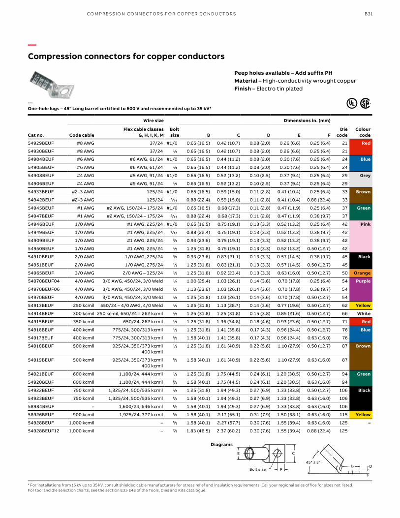
—One-hole lugs – Long barrel certified to 600 V and recommended up to 35 kV¥
¥ For installations from 16 kV up to 35 kV, consult shielded cable manufacturers for stress relief and insulation requirements. Call your regional sales office for sizes not listed.For tool and die selection charts, see the section E31-E48 of the Tools, Dies and Kits catalogue.
Diagrams
Peep holes available – Add suffix PHMaterial – High-conductivity wrought copperFinish – Electro tin plated
C
F
A
DB
E
CO M PR E SSI O N CO N N EC TO R S FO R CO PPER CO N D U C TO R S
B30 CO LO R- K E Y E D CO M PR E SSI O N CO N N EC TO R S Y S TEMS
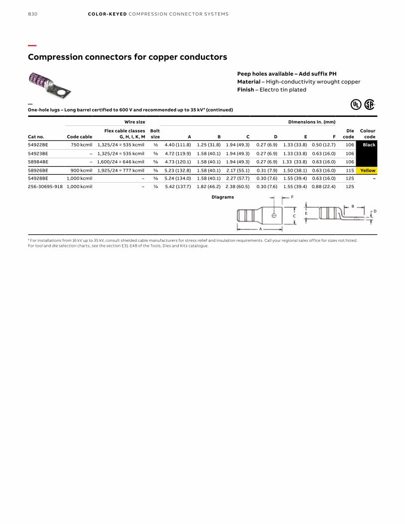
—Compression connectors for copper conductors
Cat no.
Wire size
Bolt size
Dimensions in. (mm)
Die code
Colour codeCode cable
Flex cable classes G, H, I, K, M A B C D E F
54922BE 750 kcmil 1,325/24 = 535 kcmil 1/2 4.40 (111.8) 1.25 (31.8) 1.94 (49.3) 0.27 (6.9) 1.33 (33.8) 0.50 (12.7) 106 Black
54923BE – 1,325/24 = 535 kcmil 5/8 4.72 (119.9) 1.58 (40.1) 1.94 (49.3) 0.27 (6.9) 1.33 (33.8) 0.63 (16.0) 106
58984BE – 1,600/24 = 646 kcmil 5/8 4.73 (120.1) 1.58 (40.1) 1.94 (49.3) 0.27 (6.9) 1.33 (33.8) 0.63 (16.0) 106
58926BE 900 kcmil 1,925/24 = 777 kcmil 5/8 5.23 (132.8) 1.58 (40.1) 2.17 (55.1) 0.31 (7.9) 1.50 (38.1) 0.63 (16.0) 115 Yellow
54928BE 1,000 kcmil – 5/8 5.24 (134.0) 1.58 (40.1) 2.27 (57.7) 0.30 (7.6) 1.55 (39.4) 0.63 (16.0) 125 –
256-30695-918 1,000 kcmil – 7/8 5.42 (137.7) 1.82 (46.2) 2.38 (60.5) 0.30 (7.6) 1.55 (39.4) 0.88 (22.4) 125
—One-hole lugs – Long barrel certified to 600 V and recommended up to 35 kV¥ (continued)
¥ For installations from 16 kV up to 35 kV, consult shielded cable manufacturers for stress relief and insulation requirements. Call your regional sales office for sizes not listed.For tool and die selection charts, see the section E31-E48 of the Tools, Dies and Kits catalogue.
Diagrams
Peep holes available – Add suffix PHMaterial – High-conductivity wrought copperFinish – Electro tin plated
C
F
A
DB
E
B31
—Compression connectors for copper conductors
Cat no.
Wire size
Bolt size
Dimensions in. (mm)
Die code
Colour codeCode cable
Flex cable classes G, H, I, K, M B C D E F
54929BEUF #8 AWG 37/24 #1/0 0.65 (16.5) 0.42 (10.7) 0.08 (2.0) 0.26 (6.6) 0.25 (6.4) 21 Red
54930BEUF #8 AWG 37/24 1/4 0.65 (16.5) 0.42 (10.7) 0.08 (2.0) 0.26 (6.6) 0.25 (6.4) 21
54904BEUF #6 AWG #6 AWG, 61/24 #1/0 0.65 (16.5) 0.44 (11.2) 0.08 (2.0) 0.30 (7.6) 0.25 (6.4) 24 Blue
54905BEUF #6 AWG #6 AWG, 61/24 1/4 0.65 (16.5) 0.44 (11.2) 0.08 (2.0) 0.30 (7.6) 0.25 (6.4) 24
54908BEUF #4 AWG #5 AWG, 91/24 #1/0 0.65 (16.5) 0.52 (13.2) 0.10 (2.5) 0.37 (9.4) 0.25 (6.4) 29 Grey
54906BEUF #4 AWG #5 AWG, 91/24 1/4 0.65 (16.5) 0.52 (13.2) 0.10 (2.5) 0.37 (9.4) 0.25 (6.4) 29
54933BEUF #2–3 AWG 125/24 #1/0 0.65 (16.5) 0.59 (15.0) 0.11 (2.8) 0.41 (10.4) 0.25 (6.4) 33 Brown
54942BEUF #2–3 AWG 125/24 5⁄16 0.88 (22.4) 0.59 (15.0) 0.11 (2.8) 0.41 (10.4) 0.88 (22.4) 33
54945BEUF #1 AWG #2 AWG, 150/24 – 175/24 #1/0 0.65 (16.5) 0.68 (17.3) 0.11 (2.8) 0.47 (11.9) 0.25 (6.4) 37 Green
54947BEUF #1 AWG #2 AWG, 150/24 – 175/24 5⁄16 0.88 (22.4) 0.68 (17.3) 0.11 (2.8) 0.47 (11.9) 0.38 (9.7) 37
54946BEUF 1/0 AWG #1 AWG, 225/24 #1/0 0.65 (16.5) 0.75 (19.1) 0.13 (3.3) 0.52 (13.2) 0.25 (6.4) 42 Pink
54949BEUF 1/0 AWG #1 AWG, 225/24 5⁄16 0.88 (22.4) 0.75 (19.1) 0.13 (3.3) 0.52 (13.2) 0.38 (9.7) 42
54909BEUF 1/0 AWG #1 AWG, 225/24 3/8 0.93 (23.6) 0.75 (19.1) 0.13 (3.3) 0.52 (13.2) 0.38 (9.7) 42
54950BEUF 1/0 AWG #1 AWG, 225/24 1/2 1.25 (31.8) 0.75 (19.1) 0.13 (3.3) 0.52 (13.2) 0.50 (12.7) 42
54910BEUF 2/0 AWG 1/0 AWG, 275/24 3/8 0.93 (23.6) 0.83 (21.1) 0.13 (3.3) 0.57 (14.5) 0.38 (9.7) 45 Black
54951BEUF 2/0 AWG 1/0 AWG, 275/24 1/2 1.25 (31.8) 0.83 (21.1) 0.13 (3.3) 0.57 (14.5) 0.50 (12.7) 45
54965BEUF 3/0 AWG 2/0 AWG – 325/24 1/2 1.25 (31.8) 0.92 (23.4) 0.13 (3.3) 0.63 (16.0) 0.50 (12.7) 50 Orange
54970BEUF04 4/0 AWG 3/0 AWG, 450/24, 3/0 Weld 1/4 1.00 (25.4) 1.03 (26.1) 0.14 (3.6) 0.70 (17.8) 0.25 (6.4) 54 Purple
54970BEUF06 4/0 AWG 3/0 AWG, 450/24, 3/0 Weld 3/8 1.13 (23.6) 1.03 (26.1) 0.14 (3.6) 0.70 (17.8) 0.38 (9.7) 54
54970BEUF 4/0 AWG 3/0 AWG, 450/24, 3/0 Weld 1/2 1.25 (31.8) 1.03 (26.1) 0.14 (3.6) 0.70 (17.8) 0.50 (12.7) 54
54913BEUF 250 kcmil 550/24 – 4/0 AWG, 4/0 Weld 1/2 1.25 (31.8) 1.13 (28.7) 0.14 (3.6) 0.77 (19.6) 0.50 (12.7) 62 Yellow
54914BEUF 300 kcmil 250 kcmil, 650/24 = 262 kcmil 1/2 1.25 (31.8) 1.25 (31.8) 0.15 (3.8) 0.85 (21.6) 0.50 (12.7) 66 White
54915BEUF 350 kcmil 650/24, 262 kcmil 1/2 1.25 (31.8) 1.36 (34.8) 0.18 (4.6) 0.93 (23.6) 0.50 (12.7) 71 Red
54916BEUF 400 kcmil 775/24, 300/313 kcmil 1/2 1.25 (31.8) 1.41 (35.8) 0.17 (4.3) 0.96 (24.4) 0.50 (12.7) 76 Blue
54917BEUF 400 kcmil 775/24, 300/313 kcmil 5/8 1.58 (40.1) 1.41 (35.8) 0.17 (4.3) 0.96 (24.4) 0.63 (16.0) 76
54918BEUF 500 kcmil 925/24, 350/373 kcmil400 kcmil
1/2 1.25 (31.8) 1.61 (40.9) 0.22 (5.6) 1.10 (27.9) 0.50 (12.7) 87 Brown
54919BEUF 500 kcmil 925/24, 350/373 kcmil400 kcmil
5/8 1.58 (40.1) 1.61 (40.9) 0.22 (5.6) 1.10 (27.9) 0.63 (16.0) 87
54921BEUF 600 kcmil 1,100/24, 444 kcmil 1/2 1.25 (31.8) 1.75 (44.5) 0.24 (6.1) 1.20 (30.5) 0.50 (12.7) 94 Green
54920BEUF 600 kcmil 1,100/24, 444 kcmil 5/8 1.58 (40.1) 1.75 (44.5) 0.24 (6.1) 1.20 (30.5) 0.63 (16.0) 94
54922BEUF 750 kcmil 1,325/24, 500/535 kcmil 1/2 1.25 (31.8) 1.94 (49.3) 0.27 (6.9) 1.33 (33.8) 0.50 (12.7) 106 Black
54923BEUF 750 kcmil 1,325/24, 500/535 kcmil 5/8 1.58 (40.1) 1.94 (49.3) 0.27 (6.9) 1.33 (33.8) 0.63 (16.0) 106
58984BEUF – 1,600/24, 646 kcmil 5/8 1.58 (40.1) 1.94 (49.3) 0.27 (6.9) 1.33 (33.8) 0.63 (16.0) 106
58926BEUF 900 kcmil 1,925/24, 777 kcmil 5/8 1.58 (40.1) 2.17 (55.1) 0.31 (7.9) 1.50 (38.1) 0.63 (16.0) 115 Yellow
54928BEUF 1,000 kcmil – 5/8 1.58 (40.1) 2.27 (57.7) 0.30 (7.6) 1.55 (39.4) 0.63 (16.0) 125 –
54928BEUF12 1,000 kcmil – 7/8 1.83 (46.5) 2.37 (60.2) 0.30 (7.6) 1.55 (39.4) 0.88 (22.4) 125
—One-hole lugs – 45° Long barrel certified to 600 V and recommended up to 35 kV¥
¥ For installations from 16 kV up to 35 kV, consult shielded cable manufacturers for stress relief and insulation requirements. Call your regional sales office for sizes not listed.For tool and die selection charts, see the section E31-E48 of the Tools, Dies and Kits catalogue.
Peep holes available – Add suffix PHMaterial – High-conductivity wrought copperFinish – Electro tin plated
Diagrams
45° ± 3 °DBBolt size
E
F
C
DB45° ± 3°
E
FBolt size
C
CO M PR E SSI O N CO N N EC TO R S FO R CO PPER CO N D U C TO R S
B32 CO LO R- K E Y E D CO M PR E SSI O N CO N N EC TO R S Y S TEMS
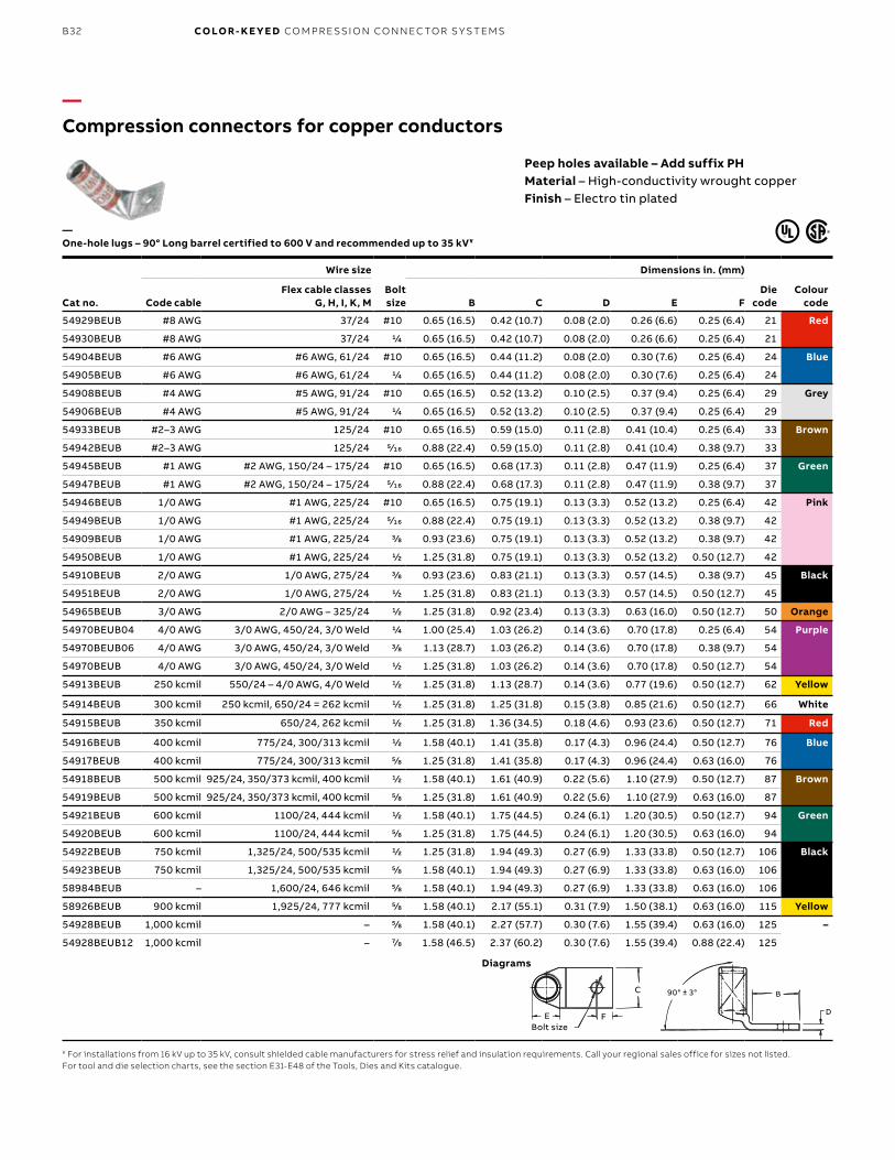
—Compression connectors for copper conductors
Cat no.
Wire size
Bolt size
Dimensions in. (mm)
Die code
Colour codeCode cable
Flex cable classes G, H, I, K, M B C D E F
54929BEUB #8 AWG 37/24 #10 0.65 (16.5) 0.42 (10.7) 0.08 (2.0) 0.26 (6.6) 0.25 (6.4) 21 Red
54930BEUB #8 AWG 37/24 1/4 0.65 (16.5) 0.42 (10.7) 0.08 (2.0) 0.26 (6.6) 0.25 (6.4) 21
54904BEUB #6 AWG #6 AWG, 61/24 #10 0.65 (16.5) 0.44 (11.2) 0.08 (2.0) 0.30 (7.6) 0.25 (6.4) 24 Blue
54905BEUB #6 AWG #6 AWG, 61/24 1/4 0.65 (16.5) 0.44 (11.2) 0.08 (2.0) 0.30 (7.6) 0.25 (6.4) 24
54908BEUB #4 AWG #5 AWG, 91/24 #10 0.65 (16.5) 0.52 (13.2) 0.10 (2.5) 0.37 (9.4) 0.25 (6.4) 29 Grey
54906BEUB #4 AWG #5 AWG, 91/24 1/4 0.65 (16.5) 0.52 (13.2) 0.10 (2.5) 0.37 (9.4) 0.25 (6.4) 29
54933BEUB #2–3 AWG 125/24 #10 0.65 (16.5) 0.59 (15.0) 0.11 (2.8) 0.41 (10.4) 0.25 (6.4) 33 Brown
54942BEUB #2–3 AWG 125/24 5⁄16 0.88 (22.4) 0.59 (15.0) 0.11 (2.8) 0.41 (10.4) 0.38 (9.7) 33
54945BEUB #1 AWG #2 AWG, 150/24 – 175/24 #10 0.65 (16.5) 0.68 (17.3) 0.11 (2.8) 0.47 (11.9) 0.25 (6.4) 37 Green
54947BEUB #1 AWG #2 AWG, 150/24 – 175/24 5⁄16 0.88 (22.4) 0.68 (17.3) 0.11 (2.8) 0.47 (11.9) 0.38 (9.7) 37
54946BEUB 1/0 AWG #1 AWG, 225/24 #10 0.65 (16.5) 0.75 (19.1) 0.13 (3.3) 0.52 (13.2) 0.25 (6.4) 42 Pink
54949BEUB 1/0 AWG #1 AWG, 225/24 5⁄16 0.88 (22.4) 0.75 (19.1) 0.13 (3.3) 0.52 (13.2) 0.38 (9.7) 42
54909BEUB 1/0 AWG #1 AWG, 225/24 3/8 0.93 (23.6) 0.75 (19.1) 0.13 (3.3) 0.52 (13.2) 0.38 (9.7) 42
54950BEUB 1/0 AWG #1 AWG, 225/24 1/2 1.25 (31.8) 0.75 (19.1) 0.13 (3.3) 0.52 (13.2) 0.50 (12.7) 42
54910BEUB 2/0 AWG 1/0 AWG, 275/24 3/8 0.93 (23.6) 0.83 (21.1) 0.13 (3.3) 0.57 (14.5) 0.38 (9.7) 45 Black
54951BEUB 2/0 AWG 1/0 AWG, 275/24 1/2 1.25 (31.8) 0.83 (21.1) 0.13 (3.3) 0.57 (14.5) 0.50 (12.7) 45
54965BEUB 3/0 AWG 2/0 AWG – 325/24 1/2 1.25 (31.8) 0.92 (23.4) 0.13 (3.3) 0.63 (16.0) 0.50 (12.7) 50 Orange
54970BEUB04 4/0 AWG 3/0 AWG, 450/24, 3/0 Weld 1/4 1.00 (25.4) 1.03 (26.2) 0.14 (3.6) 0.70 (17.8) 0.25 (6.4) 54 Purple
54970BEUB06 4/0 AWG 3/0 AWG, 450/24, 3/0 Weld 3/8 1.13 (28.7) 1.03 (26.2) 0.14 (3.6) 0.70 (17.8) 0.38 (9.7) 54
54970BEUB 4/0 AWG 3/0 AWG, 450/24, 3/0 Weld 1/2 1.25 (31.8) 1.03 (26.2) 0.14 (3.6) 0.70 (17.8) 0.50 (12.7) 54
54913BEUB 250 kcmil 550/24 – 4/0 AWG, 4/0 Weld 1/2 1.25 (31.8) 1.13 (28.7) 0.14 (3.6) 0.77 (19.6) 0.50 (12.7) 62 Yellow
54914BEUB 300 kcmil 250 kcmil, 650/24 = 262 kcmil 1/2 1.25 (31.8) 1.25 (31.8) 0.15 (3.8) 0.85 (21.6) 0.50 (12.7) 66 White
54915BEUB 350 kcmil 650/24, 262 kcmil 1/2 1.25 (31.8) 1.36 (34.5) 0.18 (4.6) 0.93 (23.6) 0.50 (12.7) 71 Red
54916BEUB 400 kcmil 775/24, 300/313 kcmil 1/2 1.58 (40.1) 1.41 (35.8) 0.17 (4.3) 0.96 (24.4) 0.50 (12.7) 76 Blue
54917BEUB 400 kcmil 775/24, 300/313 kcmil 5/8 1.25 (31.8) 1.41 (35.8) 0.17 (4.3) 0.96 (24.4) 0.63 (16.0) 76
54918BEUB 500 kcmil 925/24, 350/373 kcmil, 400 kcmil 1/2 1.58 (40.1) 1.61 (40.9) 0.22 (5.6) 1.10 (27.9) 0.50 (12.7) 87 Brown
54919BEUB 500 kcmil 925/24, 350/373 kcmil, 400 kcmil 5/8 1.25 (31.8) 1.61 (40.9) 0.22 (5.6) 1.10 (27.9) 0.63 (16.0) 87
54921BEUB 600 kcmil 1100/24, 444 kcmil 1/2 1.58 (40.1) 1.75 (44.5) 0.24 (6.1) 1.20 (30.5) 0.50 (12.7) 94 Green
54920BEUB 600 kcmil 1100/24, 444 kcmil 5/8 1.25 (31.8) 1.75 (44.5) 0.24 (6.1) 1.20 (30.5) 0.63 (16.0) 94
54922BEUB 750 kcmil 1,325/24, 500/535 kcmil 1/2 1.25 (31.8) 1.94 (49.3) 0.27 (6.9) 1.33 (33.8) 0.50 (12.7) 106 Black
54923BEUB 750 kcmil 1,325/24, 500/535 kcmil 5/8 1.58 (40.1) 1.94 (49.3) 0.27 (6.9) 1.33 (33.8) 0.63 (16.0) 106
58984BEUB – 1,600/24, 646 kcmil 5/8 1.58 (40.1) 1.94 (49.3) 0.27 (6.9) 1.33 (33.8) 0.63 (16.0) 106
58926BEUB 900 kcmil 1,925/24, 777 kcmil 5/8 1.58 (40.1) 2.17 (55.1) 0.31 (7.9) 1.50 (38.1) 0.63 (16.0) 115 Yellow
54928BEUB 1,000 kcmil – 5/8 1.58 (40.1) 2.27 (57.7) 0.30 (7.6) 1.55 (39.4) 0.63 (16.0) 125 –
54928BEUB12 1,000 kcmil – 7/8 1.58 (46.5) 2.37 (60.2) 0.30 (7.6) 1.55 (39.4) 0.88 (22.4) 125
—One-hole lugs – 90° Long barrel certified to 600 V and recommended up to 35 kV¥
¥ For installations from 16 kV up to 35 kV, consult shielded cable manufacturers for stress relief and insulation requirements. Call your regional sales office for sizes not listed.For tool and die selection charts, see the section E31-E48 of the Tools, Dies and Kits catalogue.
Peep holes available – Add suffix PHMaterial – High-conductivity wrought copperFinish – Electro tin plated
Bolt Size
90° ± 3 ° B
D
C
E F
Diagrams
E
C
FBolt size
D
B90° ± 3°
B33
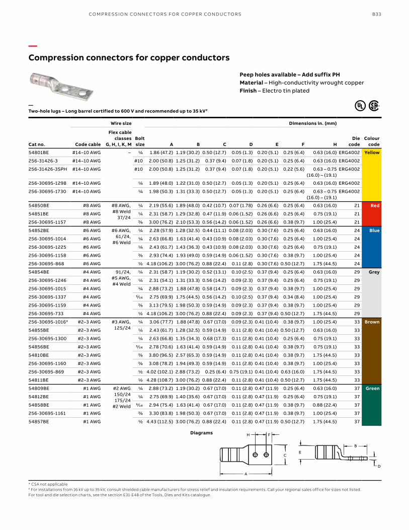
—Compression connectors for copper conductors
Peep holes available – Add suffix PHMaterial – High-conductivity wrought copperFinish – Electro tin plated
Cat no.
Wire size
Bolt size
Dimensions in. (mm)
Die code
Colour codeCode cable
Flex cable classes
G, H, I, K, M A B C D E F H
54801BE #14–10 AWG – 1/4 1.86 (47.2) 1.19 (30.2) 0.50 (12.7) 0.05 (1.3) 0.20 (5.1) 0.25 (6.4) 0.63 (16.0) ERG4002 Yellow
256-31426-3 #14–10 AWG #10 2.00 (50.8) 1.25 (31.2) 0.37 (9.4) 0.07 (1.8) 0.20 (5.1) 0.25 (6.4) 0.63 (16.0) ERG4002
256-31426-3SPH #14–10 AWG #10 2.00 (50.8) 1.25 (31.2) 0.37 (9.4) 0.07 (1.8) 0.20 (5.1) 0.22 (5.6) 0.63 – 0.75 (16.0) – (19.1)
ERG4002
256-30695-1298 #14–10 AWG 1/4 1.89 (48.0) 1.22 (31.0) 0.50 (12.7) 0.05 (1.3) 0.20 (5.1) 0.25 (6.4) 0.63 (16.0) ERG4002
256-30695-1730 #14–10 AWG 1/4 1.98 (50.3) 1.31 (33.3) 0.50 (12.7) 0.05 (1.3) 0.20 (5.1) 0.25 (6.4) 0.63 – 0.75 (16.0) – (19.1)
ERG4002
54850BE #8 AWG #8 AWG, #8 Weld
37/24
1/4 2.19 (55.6) 1.89 (48.0) 0.42 (10.7) 0.07 (1.78) 0.26 (6.6) 0.25 (6.4) 0.63 (16.0) 21 Red
54851BE #8 AWG 1/4 2.31 (58.7) 1.29 (32.8) 0.47 (11.9) 0.06 (1.52) 0.26 (6.6) 0.25 (6.4) 0.75 (19.1) 21
256-30695-1157 #8 AWG 3/8 3.00 (76.2) 2.10 (53.3) 0.56 (14.2) 0.06 (1.52) 0.26 (6.6) 0.38 (9.7) 1.00 (25.4) 21
54852BE #6 AWG #6 AWG, 61/24,
#6 Weld
1/4 2.28 (57.9) 1.28 (32.5) 0.44 (11.1) 0.08 (2.03) 0.30 (7.6) 0.25 (6.4) 0.63 (16.0) 24 Blue
256-30695-1014 #6 AWG 1/4 2.63 (66.8) 1.63 (41.4) 0.43 (10.9) 0.08 (2.03) 0.30 (7.6) 0.25 (6.4) 1.00 (25.4) 24
256-30695-1225 #6 AWG 1/4 2.43 (61.7) 1.43 (36.3) 0.43 (10.9) 0.08 (2.03) 0.30 (7.6) 0.25 (6.4) 0.75 (19.1) 24
256-30695-1158 #6 AWG 3/8 2.93 (74.4) 1.93 (49.0) 0.59 (14.9) 0.06 (1.52) 0.30 (7.6) 0.38 (9.7) 1.00 (25.4) 24
256-30695-868 #6 AWG 1/2 4.18 (106.2) 3.00 (76.2) 0.88 (22.4) 0.11 (2.8) 0.30 (7.6) 0.50 (12.7) 1.75 (44.5) 24
54854BE #4 AWG 91/24, #5 AWG, #4 Weld
1/4 2.31 (58.7) 1.19 (30.2) 0.52 (13.1) 0.10 (2.5) 0.37 (9.4) 0.25 (6.4) 0.63 (16.0) 29 Grey
256-30695-1246 #4 AWG 1/4 2.31 (54.1) 1.31 (33.3) 0.56 (14.2) 0.09 (2.3) 0.37 (9.4) 0.25 (6.4) 0.75 (19.1) 29
256-30695-1015 #4 AWG 1/4 2.88 (73.2) 1.88 (47.8) 0.58 (14.7) 0.09 (2.3) 0.37 (9.4) 0.38 (9.7) 1.00 (25.4) 29
256-30695-1337 #4 AWG 5⁄16 2.75 (69.9) 1.75 (44.5) 0.56 (14.2) 0.10 (2.5) 0.37 (9.4) 0.34 (8.4) 1.00 (25.4) 29
256-30695-1159 #4 AWG 3/8 3.13 (79.5) 1.98 (50.3) 0.59 (14.9) 0.09 (2.3) 0.37 (9.4) 0.38 (9.7) 1.00 (25.4) 29
256-30695-733 #4 AWG 1/2 4.18 (106.2) 3.00 (76.2) 0.88 (22.4) 0.09 (2.3) 0.37 (9.4) 0.50 (12.7) 1.75 (44.5) 29
256-30695-1016* #2–3 AWG #3 AWG, 125/24
1/4 3.06 (77.7) 1.88 (47.8) 0.67 (17.0) 0.09 (2.3) 0.41 (10.4) 0.38 (9.7) 1.00 (25.4) 33 Brown
54855BE #2–3 AWG 1/4 2.43 (61.7) 1.28 (32.5) 0.59 (14.9) 0.11 (2.8) 0.41 (10.4) 0.50 (12.7) 0.63 (16.0) 33
256-30695-1300 #2–3 AWG 1/4 2.63 (66.8) 1.35 (34.3) 0.68 (17.3) 0.11 (2.8) 0.41 (10.4) 0.25 (6.4) 0.75 (19.1) 33
54856BE #2–3 AWG 5⁄16 2.78 (70.6) 1.63 (41.4) 0.59 (14.9) 0.11 (2.8) 0.41 (10.4) 0.38 (9.7) 0.75 (19.1) 33
54810BE #2–3 AWG 3/8 3.80 (96.5) 2.57 (65.3) 0.59 (14.9) 0.11 (2.8) 0.41 (10.4) 0.38 (9.7) 1.75 (44.5) 33
256-30695-1160 #2–3 AWG 3/8 3.08 (78.2) 1.94 (49.3) 0.59 (14.9) 0.11 (2.8) 0.41 (10.4) 0.38 (9.7) 1.00 (25.4) 33
256-30695-869 #2–3 AWG 1/2 4.02 (102.1) 2.88 (73.2) 0.25 (6.4) 0.75 (19.1) 0.41 (10.4) 0.63 (16.0) 1.75 (44.5) 33
54811BE #2–3 AWG 1/2 4.28 (108.7) 3.00 (76.2) 0.88 (22.4) 0.11 (2.8) 0.41 (10.4) 0.50 (12.7) 1.75 (44.5) 33
54809BE #1 AWG #2 AWG150/24175/24
#2 Weld
1/4 2.88 (73.2) 1.19 (30.2) 0.67 (17.0) 0.11 (2.8) 0.47 (11.9) 0.25 (6.4) 0.63 (16.0) 37 Green
54812BE #1 AWG 1/4 2.75 (69.9) 1.40 (35.6) 0.67 (17.0) 0.11 (2.8) 0.47 (11.9) 0.25 (6.4) 0.75 (19.1) 37
54858BE #1 AWG 5⁄16 2.94 (75.4) 1.63 (41.4) 0.67 (17.0) 0.11 (2.8) 0.47 (11.9) 0.38 (9.7) 0.88 (22.4) 37
256-30695-1161 #1 AWG 3/8 3.30 (83.8) 1.98 (50.3) 0.67 (17.0) 0.11 (2.8) 0.47 (11.9) 0.38 (9.7) 1.00 (25.4) 37
54857BE #1 AWG 1/2 4.43 (112.5) 3.00 (76.2) 0.88 (22.4) 0.11 (2.8) 0.47 (11.9) 0.50 (12.7) 1.75 (44.5) 37
—Two-hole lugs – Long barrel certified to 600 V and recommended up to 35 kV¥
* CSA not applicable¥ For installations from 16 kV up to 35 kV, consult shielded cable manufacturers for stress relief and insulation requirements. Call your regional sales office for sizes not listed.For tool and die selection charts, see the section E31-E48 of the Tools, Dies and Kits catalogue.
Diagrams
A
EC
D
B
H F
C
FH
A
B
D
E
CO M PR E SSI O N CO N N EC TO R S FO R CO PPER CO N D U C TO R S
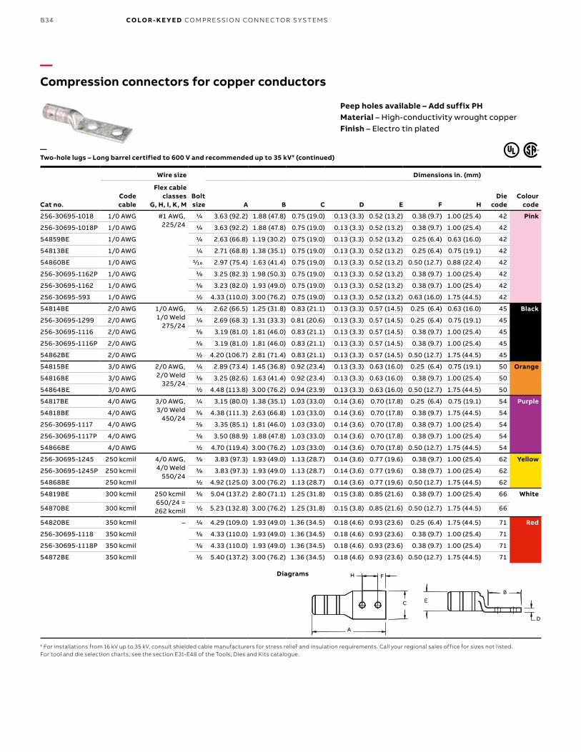
B34 CO LO R- K E Y E D CO M PR E SSI O N CO N N EC TO R S Y S TEMS
—Compression connectors for copper conductors
Peep holes available – Add suffix PHMaterial – High-conductivity wrought copperFinish – Electro tin plated
Cat no.
Wire size
Bolt size
Dimensions in. (mm)
Die code
Colour code
Code cable
Flex cable classes
G, H, I, K, M A B C D E F H
256-30695-1018 1/0 AWG #1 AWG, 225/24
1/4 3.63 (92.2) 1.88 (47.8) 0.75 (19.0) 0.13 (3.3) 0.52 (13.2) 0.38 (9.7) 1.00 (25.4) 42 Pink
256-30695-1018P 1/0 AWG 1/4 3.63 (92.2) 1.88 (47.8) 0.75 (19.0) 0.13 (3.3) 0.52 (13.2) 0.38 (9.7) 1.00 (25.4) 42
54859BE 1/0 AWG 1/4 2.63 (66.8) 1.19 (30.2) 0.75 (19.0) 0.13 (3.3) 0.52 (13.2) 0.25 (6.4) 0.63 (16.0) 42
54813BE 1/0 AWG 1/4 2.71 (68.8) 1.38 (35.1) 0.75 (19.0) 0.13 (3.3) 0.52 (13.2) 0.25 (6.4) 0.75 (19.1) 42
54860BE 1/0 AWG 5⁄16 2.97 (75.4) 1.63 (41.4) 0.75 (19.0) 0.13 (3.3) 0.52 (13.2) 0.50 (12.7) 0.88 (22.4) 42
256-30695-1162P 1/0 AWG 3/8 3.25 (82.3) 1.98 (50.3) 0.75 (19.0) 0.13 (3.3) 0.52 (13.2) 0.38 (9.7) 1.00 (25.4) 42
256-30695-1162 1/0 AWG 3/8 3.23 (82.0) 1.93 (49.0) 0.75 (19.0) 0.13 (3.3) 0.52 (13.2) 0.38 (9.7) 1.00 (25.4) 42
256-30695-593 1/0 AWG 1/2 4.33 (110.0) 3.00 (76.2) 0.75 (19.0) 0.13 (3.3) 0.52 (13.2) 0.63 (16.0) 1.75 (44.5) 42
54814BE 2/0 AWG 1/0 AWG, 1/0 Weld
275/24
1/4 2.62 (66.5) 1.25 (31.8) 0.83 (21.1) 0.13 (3.3) 0.57 (14.5) 0.25 (6.4) 0.63 (16.0) 45 Black
256-30695-1299 2/0 AWG 1/4 2.69 (68.3) 1.31 (33.3) 0.81 (20.6) 0.13 (3.3) 0.57 (14.5) 0.25 (6.4) 0.75 (19.1) 45
256-30695-1116 2/0 AWG 3/8 3.19 (81.0) 1.81 (46.0) 0.83 (21.1) 0.13 (3.3) 0.57 (14.5) 0.38 (9.7) 1.00 (25.4) 45
256-30695-1116P 2/0 AWG 3/8 3.19 (81.0) 1.81 (46.0) 0.83 (21.1) 0.13 (3.3) 0.57 (14.5) 0.38 (9.7) 1.00 (25.4) 45
54862BE 2/0 AWG 1/2 4.20 (106.7) 2.81 (71.4) 0.83 (21.1) 0.13 (3.3) 0.57 (14.5) 0.50 (12.7) 1.75 (44.5) 45
54815BE 3/0 AWG 2/0 AWG, 2/0 Weld
325/24
1/4 2.89 (73.4) 1.45 (36.8) 0.92 (23.4) 0.13 (3.3) 0.63 (16.0) 0.25 (6.4) 0.75 (19.1) 50 Orange
54816BE 3/0 AWG 3/8 3.25 (82.6) 1.63 (41.4) 0.92 (23.4) 0.13 (3.3) 0.63 (16.0) 0.38 (9.7) 1.00 (25.4) 50
54864BE 3/0 AWG 1/2 4.48 (113.8) 3.00 (76.2) 0.94 (23.9) 0.13 (3.3) 0.63 (16.0) 0.50 (12.7) 1.75 (44.5) 50
54817BE 4/0 AWG 3/0 AWG, 3/0 Weld
450/24
1/4 3.15 (80.0) 1.38 (35.1) 1.03 (33.0) 0.14 (3.6) 0.70 (17.8) 0.25 (6.4) 0.75 (19.1) 54 Purple
54818BE 4/0 AWG 3/8 4.38 (111.3) 2.63 (66.8) 1.03 (33.0) 0.14 (3.6) 0.70 (17.8) 0.38 (9.7) 1.75 (44.5) 54
256-30695-1117 4/0 AWG 3/8 3.35 (85.1) 1.81 (46.0) 1.03 (33.0) 0.14 (3.6) 0.70 (17.8) 0.38 (9.7) 1.00 (25.4) 54
256-30695-1117P 4/0 AWG 3/8 3.50 (88.9) 1.88 (47.8) 1.03 (33.0) 0.14 (3.6) 0.70 (17.8) 0.38 (9.7) 1.00 (25.4) 54
54866BE 4/0 AWG 1/2 4.70 (119.4) 3.00 (76.2) 1.03 (33.0) 0.14 (3.6) 0.70 (17.8) 0.50 (12.7) 1.75 (44.5) 54
256-30695-1245 250 kcmil 4/0 AWG, 4/0 Weld
550/24
3/8 3.83 (97.3) 1.93 (49.0) 1.13 (28.7) 0.14 (3.6) 0.77 (19.6) 0.38 (9.7) 1.00 (25.4) 62 Yellow
256-30695-1245P 250 kcmil 3/8 3.83 (97.3) 1.93 (49.0) 1.13 (28.7) 0.14 (3.6) 0.77 (19.6) 0.38 (9.7) 1.00 (25.4) 62
54868BE 250 kcmil 1/2 4.92 (125.0) 3.00 (76.2) 1.13 (28.7) 0.14 (3.6) 0.77 (19.6) 0.50 (12.7) 1.75 (44.5) 62
54819BE 300 kcmil 250 kcmil650/24 = 262 kcmil
3/8 5.04 (137.2) 2.80 (71.1) 1.25 (31.8) 0.15 (3.8) 0.85 (21.6) 0.38 (9.7) 1.00 (25.4) 66 White
54870BE 300 kcmil 1/2 5.23 (132.8) 3.00 (76.2) 1.25 (31.8) 0.15 (3.8) 0.85 (21.6) 0.50 (12.7) 1.75 (44.5) 66
54820BE 350 kcmil – 1/4 4.29 (109.0) 1.93 (49.0) 1.36 (34.5) 0.18 (4.6) 0.93 (23.6) 0.25 (6.4) 1.75 (44.5) 71 Red
256-30695-1118 350 kcmil 3/8 4.33 (110.0) 1.93 (49.0) 1.36 (34.5) 0.18 (4.6) 0.93 (23.6) 0.38 (9.7) 1.00 (25.4) 71
256-30695-1118P 350 kcmil 3/8 4.33 (110.0) 1.93 (49.0) 1.36 (34.5) 0.18 (4.6) 0.93 (23.6) 0.38 (9.7) 1.00 (25.4) 71
54872BE 350 kcmil 1/2 5.40 (137.2) 3.00 (76.2) 1.36 (34.5) 0.18 (4.6) 0.93 (23.6) 0.50 (12.7) 1.75 (44.5) 71
—Two-hole lugs – Long barrel certified to 600 V and recommended up to 35 kV¥ (continued)
¥ For installations from 16 kV up to 35 kV, consult shielded cable manufacturers for stress relief and insulation requirements. Call your regional sales office for sizes not listed.For tool and die selection charts, see the section E31-E48 of the Tools, Dies and Kits catalogue.
Diagrams
A
EC
D
B
H F
C
FH
A
B
D
E
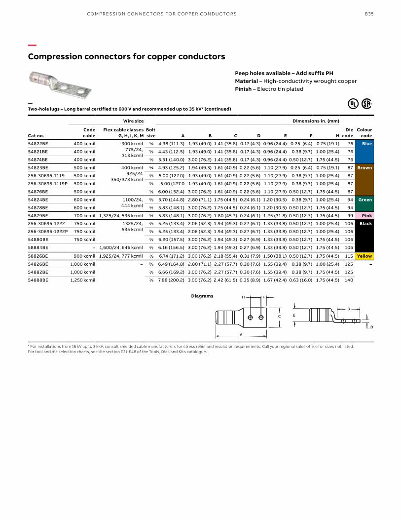
B35
—Compression connectors for copper conductors
Peep holes available – Add suffix PHMaterial – High-conductivity wrought copperFinish – Electro tin plated
Cat no.
Wire size
Bolt size
Dimensions in. (mm)
Die code
Colour code
Code cable
Flex cable classes G, H, I, K, M A B C D E F H
54822BE 400 kcmil 300 kcmil775/24,
313 kcmil
1/4 4.38 (111.3) 1.93 (49.0) 1.41 (35.8) 0.17 (4.3) 0.96 (24.4) 0.25 (6.4) 0.75 (19.1) 76 Blue
54821BE 400 kcmil 3/8 4.43 (112.5) 1.93 (49.0) 1.41 (35.8) 0.17 (4.3) 0.96 (24.4) 0.38 (9.7) 1.00 (25.4) 76
54874BE 400 kcmil 1/2 5.51 (140.0) 3.00 (76.2) 1.41 (35.8) 0.17 (4.3) 0.96 (24.4) 0.50 (12.7) 1.75 (44.5) 76
54823BE 500 kcmil 400 kcmil925/24
350/373 kcmil
1/4 4.93 (125.2) 1.94 (49.3) 1.61 (40.9) 0.22 (5.6) 1.10 (27.9) 0.25 (6.4) 0.75 (19.1) 87 Brown
256-30695-1119 500 kcmil 3/8 5.00 (127.0) 1.93 (49.0) 1.61 (40.9) 0.22 (5.6) 1.10 (27.9) 0.38 (9.7) 1.00 (25.4) 87
256-30695-1119P 500 kcmil 3/8 5.00 (127.0 1.93 (49.0) 1.61 (40.9) 0.22 (5.6) 1.10 (27.9) 0.38 (9.7) 1.00 (25.4) 87
54876BE 500 kcmil 1/2 6.00 (152.4) 3.00 (76.2) 1.61 (40.9) 0.22 (5.6) 1.10 (27.9) 0.50 (12.7) 1.75 (44.5) 87
54824BE 600 kcmil 1100/24, 444 kcmil
3/8 5.70 (144.8) 2.80 (71.1) 1.75 (44.5) 0.24 (6.1) 1.20 (30.5) 0.38 (9.7) 1.00 (25.4) 94 Green
54878BE 600 kcmil 1/2 5.83 (148.1) 3.00 (76.2) 1.75 (44.5) 0.24 (6.1) 1.20 (30.5) 0.50 (12.7) 1.75 (44.5) 94
54879BE 700 kcmil 1,325/24, 535 kcmil 1/2 5.83 (148.1) 3.00 (76.2) 1.80 (45.7) 0.24 (6.1) 1.25 (31.8) 0.50 (12.7) 1.75 (44.5) 99 Pink
256-30695-1222 750 kcmil 1325/24, 535 kcmil
3/8 5.25 (133.4) 2.06 (52.3) 1.94 (49.3) 0.27 (6.7) 1.33 (33.8) 0.50 (12.7) 1.00 (25.4) 106 Black
256-30695-1222P 750 kcmil 3/8 5.25 (133.4) 2.06 (52.3) 1.94 (49.3) 0.27 (6.7) 1.33 (33.8) 0.50 (12.7) 1.00 (25.4) 106
54880BE 750 kcmil 1/2 6.20 (157.5) 3.00 (76.2) 1.94 (49.3) 0.27 (6.9) 1.33 (33.8) 0.50 (12.7) 1.75 (44.5) 106
58884BE – 1,600/24, 646 kcmil 1/2 6.16 (156.5) 3.00 (76.2) 1.94 (49.3) 0.27 (6.9) 1.33 (33.8) 0.50 (12.7) 1.75 (44.5) 106
58826BE 900 kcmil 1,925/24, 777 kcmil 1/2 6.74 (171.2) 3.00 (76.2) 2.18 (55.4) 0.31 (7.9) 1.50 (38.1) 0.50 (12.7) 1.75 (44.5) 115 Yellow
54826BE 1,000 kcmil – 3/8 6.49 (164.8) 2.80 (71.1) 2.27 (57.7) 0.30 (7.6) 1.55 (39.4) 0.38 (9.7) 1.00 (25.4) 125 –
54882BE 1,000 kcmil 1/2 6.66 (169.2) 3.00 (76.2) 2.27 (57.7) 0.30 (7.6) 1.55 (39.4) 0.38 (9.7) 1.75 (44.5) 125
54888BE 1,250 kcmil 1/2 7.88 (200.2) 3.00 (76.2) 2.42 (61.5) 0.35 (8.9) 1.67 (42.4) 0.63 (16.0) 1.75 (44.5) 140
—Two-hole lugs – Long barrel certified to 600 V and recommended up to 35 kV¥ (continued)
¥ For installations from 16 kV up to 35 kV, consult shielded cable manufacturers for stress relief and insulation requirements. Call your regional sales office for sizes not listed.For tool and die selection charts, see the section E31-E48 of the Tools, Dies and Kits catalogue.
Diagrams
A
EC
D
B
H F
C
FH
A
B
D
E
CO M PR E SSI O N CO N N EC TO R S FO R CO PPER CO N D U C TO R S
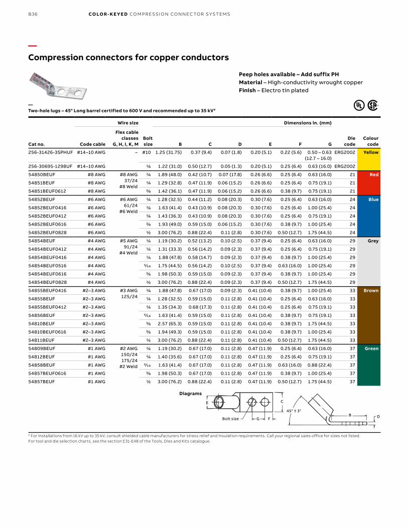
B36 CO LO R- K E Y E D CO M PR E SSI O N CO N N EC TO R S Y S TEMS
—Compression connectors for copper conductors
Peep holes available – Add suffix PHMaterial – High-conductivity wrought copperFinish – Electro tin plated
Cat no.
Wire size
Bolt size
Dimensions in. (mm)
Die code
Colour codeCode cable
Flex cable classes
G, H, I, K, M B C D E F G
256-31426-3SPHUF #14–10 AWG – #10 1.25 (31.75) 0.37 (9.4) 0.07 (1.8) 0.20 (5.1) 0.22 (5.6) 0.50 – 0.63 (12.7 – 16.0)
ERG2002 Yellow
256-30695-1298UF #14–10 AWG 1/4 1.22 (31.0) 0.50 (12.7) 0.05 (1.3) 0.20 (5.1) 0.25 (6.4) 0.63 (16.0) ERG2002
54850BEUF #8 AWG #8 AWG37/24
#8 Weld
1/4 1.89 (48.0) 0.42 (10.7) 0.07 (17.8) 0.26 (6.6) 0.25 (6.4) 0.63 (16.0) 21 Red
54851BEUF #8 AWG 1/4 1.29 (32.8) 0.47 (11.9) 0.06 (15.2) 0.26 (6.6) 0.25 (6.4) 0.75 (19.1) 21
54851BEUF0612 #8 AWG 3/8 1.42 (36.1) 0.47 (11.9) 0.06 (15.2) 0.26 (6.6) 0.38 (9.7) 0.75 (19.1) 21
54852BEUF #6 AWG #6 AWG61/24
#6 Weld
1/4 1.28 (32.5) 0.44 (11.2) 0.08 (20.3) 0.30 (7.6) 0.25 (6.4) 0.63 (16.0) 24 Blue
54852BEUF0416 #6 AWG 1/4 1.63 (41.4) 0.43 (10.9) 0.08 (20.3) 0.30 (7.6) 0.25 (6.4) 1.00 (25.4) 24
54852BEUF0412 #6 AWG 1/4 1.43 (36.3) 0.43 (10.9) 0.08 (20.3) 0.30 (7.6) 0.25 (6.4) 0.75 (19.1) 24
54852BEUF0616 #6 AWG 3/8 1.93 (49.0) 0.59 (15.0) 0.06 (15.2) 0.30 (7.6) 0.38 (9.7) 1.00 (25.4) 24
54852BEUF0828 #6 AWG 1/2 3.00 (76.2) 0.88 (22.4) 0.11 (2.8) 0.30 (7.6) 0.50 (12.7) 1.75 (44.5) 24
54854BEUF #4 AWG #5 AWG91/24
#4 Weld
1/4 1.19 (30.2) 0.52 (13.2) 0.10 (2.5) 0.37 (9.4) 0.25 (6.4) 0.63 (16.0) 29 Grey
54854BEUF0412 #4 AWG 1/4 1.31 (33.3) 0.56 (14.2) 0.09 (2.3) 0.37 (9.4) 0.25 (6.4) 0.75 (19.1) 29
54854BEUF0416 #4 AWG 1/4 1.88 (47.8) 0.58 (14.7) 0.09 (2.3) 0.37 (9.4) 0.38 (9.7) 1.00 (25.4) 29
54854BEUF0516 #4 AWG 5⁄16 1.75 (44.5) 0.56 (14.2) 0.10 (2.5) 0.37 (9.4) 0.63 (16.0) 1.00 (25.4) 29
54854BEUF0616 #4 AWG 3/8 1.98 (50.3) 0.59 (15.0) 0.09 (2.3) 0.37 (9.4) 0.38 (9.7) 1.00 (25.4) 29
54854BEUF0828 #4 AWG 1/2 3.00 (76.2) 0.88 (22.4) 0.09 (2.3) 0.37 (9.4) 0.50 (12.7) 1.75 (44.5) 29
54855BEUF0416 #2–3 AWG #3 AWG125/24
1/4 1.88 (47.8) 0.67 (17.0) 0.09 (2.3) 0.41 (10.4) 0.38 (9.7) 1.00 (25.4) 33 Brown
54855BEUF #2–3 AWG 1/4 1.28 (32.5) 0.59 (15.0) 0.11 (2.8) 0.41 (10.4) 0.25 (6.4) 0.63 (16.0) 33
54855BEUF0412 #2–3 AWG 1/4 1.35 (34.3) 0.68 (17.3) 0.11 (2.8) 0.41 (10.4) 0.25 (6.4) 0.75 (19.1) 33
54856BEUF #2–3 AWG 5⁄16 1.63 (41.4) 0.59 (15.0) 0.11 (2.8) 0.41 (10.4) 0.38 (9.7) 0.75 (19.1) 33
54810BEUF #2–3 AWG 3/8 2.57 (65.3) 0.59 (15.0) 0.11 (2.8) 0.41 (10.4) 0.38 (9.7) 1.75 (44.5) 33
54810BEUF0616 #2–3 AWG 3/8 1.94 (49.3) 0.59 (15.0) 0.11 (2.8) 0.41 (10.4) 0.38 (9.7) 1.00 (25.4) 33
54811BEUF #2–3 AWG 1/2 3.00 (76.2) 0.88 (22.4) 0.11 (2.8) 0.41 (10.4) 0.50 (12.7) 1.75 (44.5) 33
54809BEUF #1 AWG #2 AWG150/24175/24
#2 Weld
1/4 1.19 (30.2) 0.67 (17.0) 0.11 (2.8) 0.47 (11.9) 0.25 (6.4) 0.63 (16.0) 37 Green
54812BEUF #1 AWG 1/4 1.40 (35.6) 0.67 (17.0) 0.11 (2.8) 0.47 (11.9) 0.25 (6.4) 0.75 (19.1) 37
54858BEUF #1 AWG 5⁄16 1.63 (41.4) 0.67 (17.0) 0.11 (2.8) 0.47 (11.9) 0.63 (16.0) 0.88 (22.4) 37
54857BEUF0616 #1 AWG 3/8 1.98 (50.3) 0.67 (17.0) 0.11 (2.8) 0.47 (11.9) 0.38 (9.7) 1.00 (25.4) 37
54857BEUF #1 AWG 1/2 3.00 (76.2) 0.88 (22.4) 0.11 (2.8) 0.47 (11.9) 0.50 (12.7) 1.75 (44.5) 37
—Two-hole lugs – 45° Long barrel certified to 600 V and recommended up to 35 kV¥
¥ For installations from 16 kV up to 35 kV, consult shielded cable manufacturers for stress relief and insulation requirements. Call your regional sales office for sizes not listed.For tool and die selection charts, see the section E31-E48 of the Tools, Dies and Kits catalogue.
Diagrams
Bolt Size
E C
FG
45° ± 3 °
DBFBolt size G
E C
B D45° ± 3°
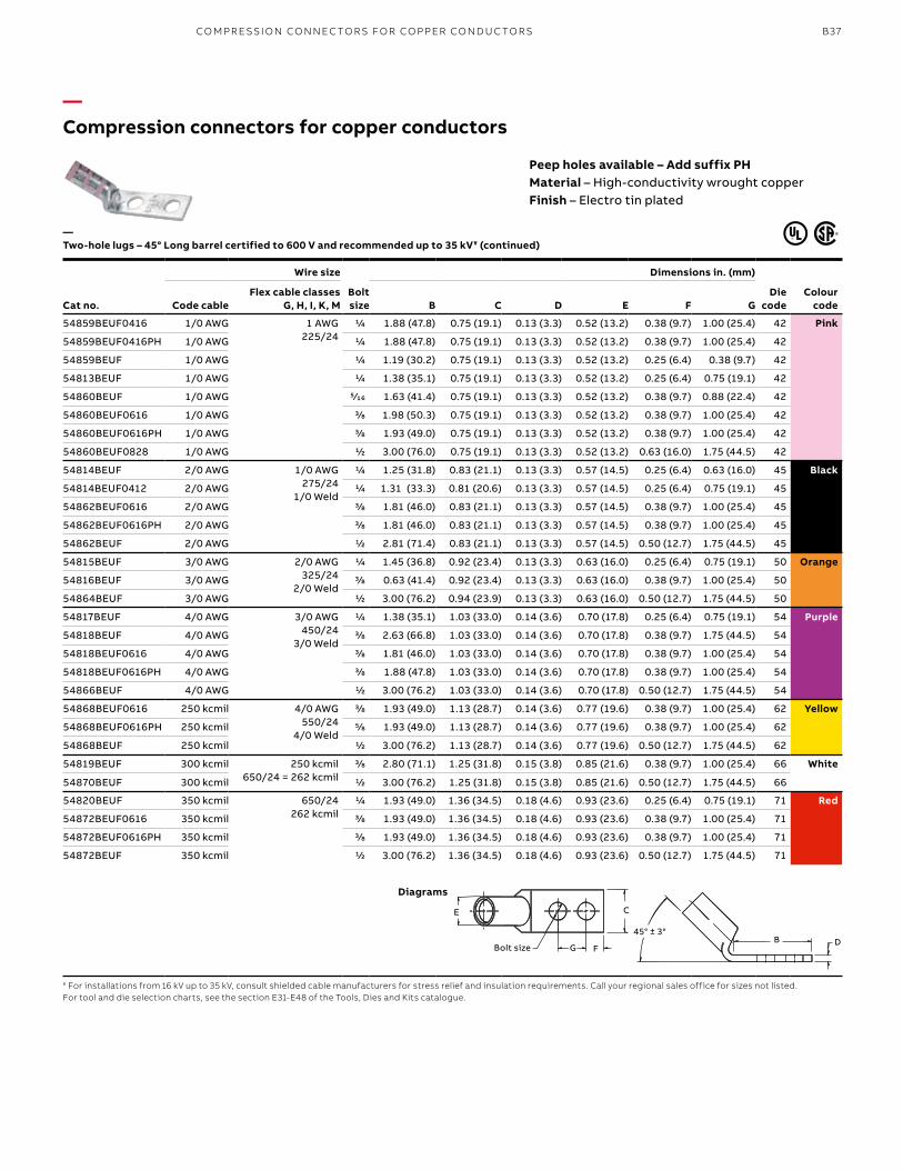
B37
—Compression connectors for copper conductors
Peep holes available – Add suffix PHMaterial – High-conductivity wrought copperFinish – Electro tin plated
Cat no.
Wire size
Bolt size
Dimensions in. (mm)
Die code
Colour codeCode cable
Flex cable classes G, H, I, K, M B C D E F G
54859BEUF0416 1/0 AWG 1 AWG225/24
1/4 1.88 (47.8) 0.75 (19.1) 0.13 (3.3) 0.52 (13.2) 0.38 (9.7) 1.00 (25.4) 42 Pink
54859BEUF0416PH 1/0 AWG 1/4 1.88 (47.8) 0.75 (19.1) 0.13 (3.3) 0.52 (13.2) 0.38 (9.7) 1.00 (25.4) 42
54859BEUF 1/0 AWG 1/4 1.19 (30.2) 0.75 (19.1) 0.13 (3.3) 0.52 (13.2) 0.25 (6.4) 0.38 (9.7) 42
54813BEUF 1/0 AWG 1/4 1.38 (35.1) 0.75 (19.1) 0.13 (3.3) 0.52 (13.2) 0.25 (6.4) 0.75 (19.1) 42
54860BEUF 1/0 AWG 5⁄16 1.63 (41.4) 0.75 (19.1) 0.13 (3.3) 0.52 (13.2) 0.38 (9.7) 0.88 (22.4) 42
54860BEUF0616 1/0 AWG 3/8 1.98 (50.3) 0.75 (19.1) 0.13 (3.3) 0.52 (13.2) 0.38 (9.7) 1.00 (25.4) 42
54860BEUF0616PH 1/0 AWG 3/8 1.93 (49.0) 0.75 (19.1) 0.13 (3.3) 0.52 (13.2) 0.38 (9.7) 1.00 (25.4) 42
54860BEUF0828 1/0 AWG 1/2 3.00 (76.0) 0.75 (19.1) 0.13 (3.3) 0.52 (13.2) 0.63 (16.0) 1.75 (44.5) 42
54814BEUF 2/0 AWG 1/0 AWG275/24
1/0 Weld
1/4 1.25 (31.8) 0.83 (21.1) 0.13 (3.3) 0.57 (14.5) 0.25 (6.4) 0.63 (16.0) 45 Black
54814BEUF0412 2/0 AWG 1/4 1.31 (33.3) 0.81 (20.6) 0.13 (3.3) 0.57 (14.5) 0.25 (6.4) 0.75 (19.1) 45
54862BEUF0616 2/0 AWG 3/8 1.81 (46.0) 0.83 (21.1) 0.13 (3.3) 0.57 (14.5) 0.38 (9.7) 1.00 (25.4) 45
54862BEUF0616PH 2/0 AWG 3/8 1.81 (46.0) 0.83 (21.1) 0.13 (3.3) 0.57 (14.5) 0.38 (9.7) 1.00 (25.4) 45
54862BEUF 2/0 AWG 1/2 2.81 (71.4) 0.83 (21.1) 0.13 (3.3) 0.57 (14.5) 0.50 (12.7) 1.75 (44.5) 45
54815BEUF 3/0 AWG 2/0 AWG325/24
2/0 Weld
1/4 1.45 (36.8) 0.92 (23.4) 0.13 (3.3) 0.63 (16.0) 0.25 (6.4) 0.75 (19.1) 50 Orange
54816BEUF 3/0 AWG 3/8 0.63 (41.4) 0.92 (23.4) 0.13 (3.3) 0.63 (16.0) 0.38 (9.7) 1.00 (25.4) 50
54864BEUF 3/0 AWG 1/2 3.00 (76.2) 0.94 (23.9) 0.13 (3.3) 0.63 (16.0) 0.50 (12.7) 1.75 (44.5) 50
54817BEUF 4/0 AWG 3/0 AWG450/24
3/0 Weld
1/4 1.38 (35.1) 1.03 (33.0) 0.14 (3.6) 0.70 (17.8) 0.25 (6.4) 0.75 (19.1) 54 Purple
54818BEUF 4/0 AWG 3/8 2.63 (66.8) 1.03 (33.0) 0.14 (3.6) 0.70 (17.8) 0.38 (9.7) 1.75 (44.5) 54
54818BEUF0616 4/0 AWG 3/8 1.81 (46.0) 1.03 (33.0) 0.14 (3.6) 0.70 (17.8) 0.38 (9.7) 1.00 (25.4) 54
54818BEUF0616PH 4/0 AWG 3/8 1.88 (47.8) 1.03 (33.0) 0.14 (3.6) 0.70 (17.8) 0.38 (9.7) 1.00 (25.4) 54
54866BEUF 4/0 AWG 1/2 3.00 (76.2) 1.03 (33.0) 0.14 (3.6) 0.70 (17.8) 0.50 (12.7) 1.75 (44.5) 54
54868BEUF0616 250 kcmil 4/0 AWG550/24
4/0 Weld
3/8 1.93 (49.0) 1.13 (28.7) 0.14 (3.6) 0.77 (19.6) 0.38 (9.7) 1.00 (25.4) 62 Yellow
54868BEUF0616PH 250 kcmil 5/8 1.93 (49.0) 1.13 (28.7) 0.14 (3.6) 0.77 (19.6) 0.38 (9.7) 1.00 (25.4) 62
54868BEUF 250 kcmil 1/2 3.00 (76.2) 1.13 (28.7) 0.14 (3.6) 0.77 (19.6) 0.50 (12.7) 1.75 (44.5) 62
54819BEUF 300 kcmil 250 kcmil650/24 = 262 kcmil
3/8 2.80 (71.1) 1.25 (31.8) 0.15 (3.8) 0.85 (21.6) 0.38 (9.7) 1.00 (25.4) 66 White
54870BEUF 300 kcmil 1/2 3.00 (76.2) 1.25 (31.8) 0.15 (3.8) 0.85 (21.6) 0.50 (12.7) 1.75 (44.5) 66
54820BEUF 350 kcmil 650/24262 kcmil
1/4 1.93 (49.0) 1.36 (34.5) 0.18 (4.6) 0.93 (23.6) 0.25 (6.4) 0.75 (19.1) 71 Red
54872BEUF0616 350 kcmil 3/8 1.93 (49.0) 1.36 (34.5) 0.18 (4.6) 0.93 (23.6) 0.38 (9.7) 1.00 (25.4) 71
54872BEUF0616PH 350 kcmil 3/8 1.93 (49.0) 1.36 (34.5) 0.18 (4.6) 0.93 (23.6) 0.38 (9.7) 1.00 (25.4) 71
54872BEUF 350 kcmil 1/2 3.00 (76.2) 1.36 (34.5) 0.18 (4.6) 0.93 (23.6) 0.50 (12.7) 1.75 (44.5) 71
—Two-hole lugs – 45° Long barrel certified to 600 V and recommended up to 35 kV¥ (continued)
¥ For installations from 16 kV up to 35 kV, consult shielded cable manufacturers for stress relief and insulation requirements. Call your regional sales office for sizes not listed.For tool and die selection charts, see the section E31-E48 of the Tools, Dies and Kits catalogue.
Diagrams
Bolt Size
E C
FG
45° ± 3 °
DBFBolt size G
E C
B D45° ± 3°
CO M PR E SSI O N CO N N EC TO R S FO R CO PPER CO N D U C TO R S
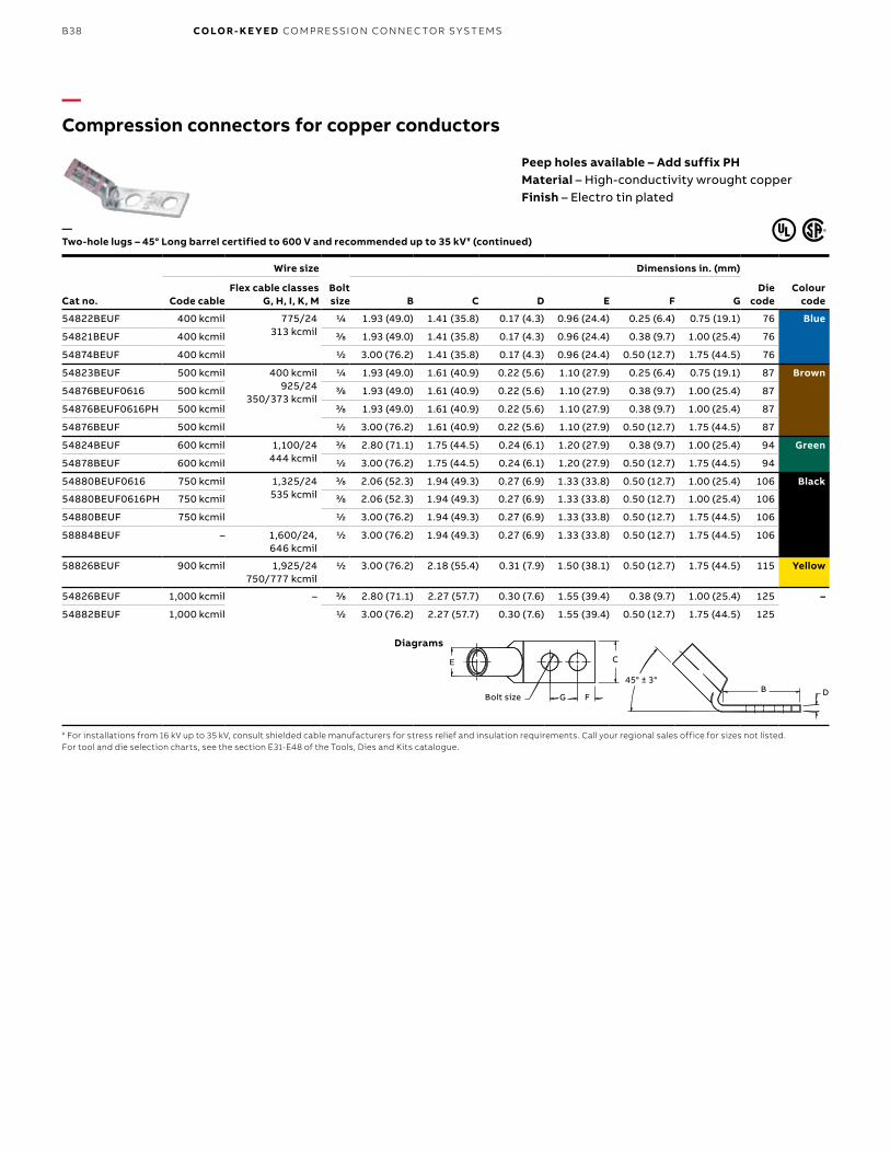
B38 CO LO R- K E Y E D CO M PR E SSI O N CO N N EC TO R S Y S TEMS
—Compression connectors for copper conductors
Peep holes available – Add suffix PHMaterial – High-conductivity wrought copperFinish – Electro tin plated
Cat no.
Wire size
Bolt size
Dimensions in. (mm)
Die code
Colour codeCode cable
Flex cable classes G, H, I, K, M B C D E F G
54822BEUF 400 kcmil 775/24313 kcmil
1/4 1.93 (49.0) 1.41 (35.8) 0.17 (4.3) 0.96 (24.4) 0.25 (6.4) 0.75 (19.1) 76 Blue
54821BEUF 400 kcmil 3/8 1.93 (49.0) 1.41 (35.8) 0.17 (4.3) 0.96 (24.4) 0.38 (9.7) 1.00 (25.4) 76
54874BEUF 400 kcmil 1/2 3.00 (76.2) 1.41 (35.8) 0.17 (4.3) 0.96 (24.4) 0.50 (12.7) 1.75 (44.5) 76
54823BEUF 500 kcmil 400 kcmil925/24
350/373 kcmil
1/4 1.93 (49.0) 1.61 (40.9) 0.22 (5.6) 1.10 (27.9) 0.25 (6.4) 0.75 (19.1) 87 Brown
54876BEUF0616 500 kcmil 3/8 1.93 (49.0) 1.61 (40.9) 0.22 (5.6) 1.10 (27.9) 0.38 (9.7) 1.00 (25.4) 87
54876BEUF0616PH 500 kcmil 3/8 1.93 (49.0) 1.61 (40.9) 0.22 (5.6) 1.10 (27.9) 0.38 (9.7) 1.00 (25.4) 87
54876BEUF 500 kcmil 1/2 3.00 (76.2) 1.61 (40.9) 0.22 (5.6) 1.10 (27.9) 0.50 (12.7) 1.75 (44.5) 87
54824BEUF 600 kcmil 1,100/24444 kcmil
3/8 2.80 (71.1) 1.75 (44.5) 0.24 (6.1) 1.20 (27.9) 0.38 (9.7) 1.00 (25.4) 94 Green
54878BEUF 600 kcmil 1/2 3.00 (76.2) 1.75 (44.5) 0.24 (6.1) 1.20 (27.9) 0.50 (12.7) 1.75 (44.5) 94
54880BEUF0616 750 kcmil 1,325/24535 kcmil
3/8 2.06 (52.3) 1.94 (49.3) 0.27 (6.9) 1.33 (33.8) 0.50 (12.7) 1.00 (25.4) 106 Black
54880BEUF0616PH 750 kcmil 3/8 2.06 (52.3) 1.94 (49.3) 0.27 (6.9) 1.33 (33.8) 0.50 (12.7) 1.00 (25.4) 106
54880BEUF 750 kcmil 1/2 3.00 (76.2) 1.94 (49.3) 0.27 (6.9) 1.33 (33.8) 0.50 (12.7) 1.75 (44.5) 106
58884BEUF – 1,600/24, 646 kcmil
1/2 3.00 (76.2) 1.94 (49.3) 0.27 (6.9) 1.33 (33.8) 0.50 (12.7) 1.75 (44.5) 106
58826BEUF 900 kcmil 1,925/24750/777 kcmil
1/2 3.00 (76.2) 2.18 (55.4) 0.31 (7.9) 1.50 (38.1) 0.50 (12.7) 1.75 (44.5) 115 Yellow
54826BEUF 1,000 kcmil – 3/8 2.80 (71.1) 2.27 (57.7) 0.30 (7.6) 1.55 (39.4) 0.38 (9.7) 1.00 (25.4) 125 –
54882BEUF 1,000 kcmil 1/2 3.00 (76.2) 2.27 (57.7) 0.30 (7.6) 1.55 (39.4) 0.50 (12.7) 1.75 (44.5) 125
—Two-hole lugs – 45° Long barrel certified to 600 V and recommended up to 35 kV¥ (continued)
¥ For installations from 16 kV up to 35 kV, consult shielded cable manufacturers for stress relief and insulation requirements. Call your regional sales office for sizes not listed.For tool and die selection charts, see the section E31-E48 of the Tools, Dies and Kits catalogue.
Diagrams
Bolt Size
E C
FG
45° ± 3 °
DBFBolt size G
E C
B D45° ± 3°
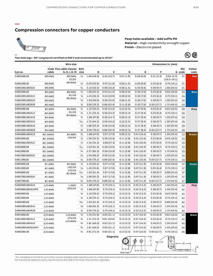
B39
—Compression connectors for copper conductors
Peep holes available – Add suffix PHMaterial – High-conductivity wrought copperFinish – Electro tin plated
Cat no.
Wire size
Bolt size
Dimensions in. (mm)
Die code
Colour code
Code cable
Flex cable classes G, H, I, K, M B C D E F G
54850BEUB #8 AWG #8 AWG37/24
#8 Weld
1/4 1.89 (48.0) 0.42 (10.7) 0.07 (1.8) 0.26 (6.6) 0.21 (5.3) 0.63–0.75 (16.0–19.1)
21 Red
54851BEUB #8 AWG 1/4 0.29 (32.8) 0.47 (11.9) 0.06 (1.5) 0.26 (6.6) 0.25 (6.4) 0.75 (19.1) 21
54851BEUB0616 #8 AWG 3/8 2.10 (53.3) 0.56 (14.2) 0.06 (1.5) 0.26 (6.6) 0.38 (9.7) 1.00 (25.4) 21
54852BEUB #6 AWG #6 AWG61/24
#6 Weld
1/4 1.28 (32.5) 0.44 (11.2) 0.08 (2.0) 0.30 (7.6) 0.25 (6.4) 0.63 (16.0) 24 Blue
54852BEUB0412 #6 AWG 1/4 1.43 (36.3) 0.43 (10.9) 0.08 (2.0) 0.30 (7.6) 0.25 (6.4) 0.75 (19.1) 24
54852BEUB0616 #6 AWG 3/8 1.93 (49.0) 0.59 (15.0) 0.06 (1.5) 0.30 (7.6) 0.38 (9.7) 1.00 (25.4) 24
54852BEUB0828 #6 AWG 1/2 3.00 (76.2) 0.88 (22.4) 0.11 (2.8) 0.30 (7.6) 0.50 (12.7) 1.75 (44.5) 24
54854BEUB #4 AWG #5 AWG91/24
#4 Weld
1/4 1.19 (30.2) 0.52 (13.2) 0.10 (2.5) 0.37 (9.4) 0.25 (6.4) 0.63 (16.0) 29 Grey
54854BEUB0412 #4 AWG 1/4 1.31 (33.3) 0.56 (14.2) 0.09 (2.3) 0.37 (9.4) 0.25 (6.4) 0.75 (19.1) 29
54854BEUB0416 #4 AWG 1/4 1.88 (47.8) 0.58 (14.7) 0.09 (2.3) 0.37 (9.4) 0.38 (9.7) 1.00 (25.4) 29
54854BEUB0516 #4 AWG 5⁄16 1.75 (44.5) 0.56 (14.2) 0.10 (2.5) 0.37 (9.4) 0.38 (9.7) 1.00 (25.4) 29
54854BEUB0616 #4 AWG 3/8 1.98 (50.3) 0.59 (15.0) 0.09 (2.3) 0.37 (9.4) 0.38 (9.7) 1.00 (25.4) 29
54854BEUB0828 #4 AWG 1/2 3.00 (76.2) 0.88 (22.4) 0.09 (2.3) 0.37 (9.4) 0.50 (12.7) 1.75 (44.5) 29
54858BEUB0416 #2–3AWG #3 AWG125/24
1/4 1.88 (47.8) 0.67 (17.0) 0.09 (2.3) 0.41 (10.4) 0.38 (9.7) 1.00 (25.4) 33 Brown
54855BEUB #2–3AWG 1/4 1.28 (32.5) 0.59 (15.0) 0.11 (2.8) 0.41 (10.4) 0.25 (6.4) 0.63 (16.0) 33
54855BEUB0412 #2–3AWG 1/4 1.35 (34.3) 0.68 (17.3) 0.11 (2.8) 0.41 (10.4) 0.25 (6.4) 0.75 (19.1) 33
54856BEUB #2–3AWG 5⁄16 1.63 (41.4) 0.59 (15.0) 0.11 (2.8) 0.41 (10.4) 0.38 (9.7) 0.75 (19.1) 33
54810BEUB #2–3AWG 3/8 2.57 (65.3) 0.59 (15.0) 0.11 (2.8) 0.41 (10.4) 0.38 (9.7) 1.75 (44.5) 33
54810BEUB0616 #2–3AWG 3/8 1.94 (49.3) 0.59 (15.0) 0.11 (2.8) 0.41 (10.4) 0.38 (9.7) 1.00 (25.4) 33
54811BEUB #2–3AWG 1/2 3.00 (76.2) 0.88 (22.4) 0.11 (2.8) 0.41 (10.4) 0.50 (12.7) 0.75 (19.1) 33
54809BEUB #1 AWG #2 AWG150/24175/24
#2 Weld
1/4 1.19 (30.2) 0.67 (17.0) 0.11 (2.8) 0.47 (11.9) 0.25 (6.4) 0.63 (16.0) 37 Green
54812BEUB #1 AWG 1/4 1.40 (35.6) 0.67 (17.0) 0.11 (2.8) 0.47 (11.9) 0.25 (6.4) 0.75 (19.1) 37
54858BEUB #1 AWG 5⁄16 1.63 (41.4) 0.67 (17.0) 0.11 (2.8) 0.47 (11.9) 0.38 (9.7) 0.88 (22.4) 37
54857BEUB0616 #1 AWG 3/8 1.98 (50.3) 0.67 (17.0) 0.11 (2.8) 0.47 (11.9) 0.38 (9.7) 1.00 (25.4) 37
54857BEUB #1 AWG 1/2 3.00 (76.2) 0.88 (22.4) 0.11 (2.8) 0.47 (11.9) 0.50 (12.7) 1.75 (44.5) 37
54859BEUB0416 1/0 AWG 1 AWG225/24
1/4 1.88 (47.8) 0.75 (19.1) 0.13 (3.3) 0.52 (13.2) 0.38 (9.7) 1.00 (25.4) 42 Pink
54859BEUB0416PH 1/0 AWG 1/4 1.88 (47.8) 0.75 (19.1) 0.13 (3.3) 0.52 (13.2) 0.38 (9.7) 1.00 (25.4) 42
54859BEUB 1/0 AWG 1/4 1.19 (30.2) 0.75 (19.1) 0.13 (3.3) 0.52 (13.2) 0.25 (6.4) 0.63 (16.0) 42
54813BEUB 1/0 AWG 1/4 1.38 (35.1) 0.75 (19.1) 0.13 (3.3) 0.52 (13.2) 0.25 (6.4) 0.75 (19.1) 42
54860BEUB 1/0 AWG 5⁄16 1.63 (41.4) 0.75 (19.1) 0.13 (3.3) 0.52 (13.2) 0.38 (9.7) 0.88 (22.4) 42
54860BEUB0616 1/0 AWG 3/8 1.98 (50.3) 0.75 (19.1) 0.13 (3.3) 0.52 (13.2) 0.38 (9.7) 1.00 (25.4) 42
54860BEUB0828 1/0 AWG 1/2 3.00 (76.2) 0.75 (19.1) 0.13 (3.3) 0.52 (13.2) 0.38 (9.7) 1.75 (44.5) 42
54814BEUB 2/0 AWG 1/0 AWG275/24
1/0 Weld
1/4 1.25 (31.8) 0.83 (21.1) 0.13 (3.3) 0.57 (14.5) 0.25 (6.4) 0.63 (16.0) 45 Black
54814BEUB0412 2/0 AWG 1/4 1.31 (33.3) 0.81 (20.6) 0.13 (3.3) 0.57 (14.5) 0.25 (6.4) 0.75 (19.1) 45
54862BEUB0616 2/0 AWG 3/8 1.81 (46.0) 0.83 (21.1) 0.13 (3.3) 0.57 (14.5) 0.38 (9.7) 1.00 (25.4) 45
54862BEUB0616PH 2/0 AWG 3/8 1.81 (46.0) 0.83 (21.1) 0.13 (3.3) 0.57 (14.5) 0.38 (9.7) 1.00 (25.4) 45
54862BEUB 2/0 AWG 1/2 2.81 (71.4) 0.83 (21.1) 0.13 (3.3) 0.57 (14.5) 0.50 (12.7) 0.75 (19.1) 45
—Two-hole lugs – 90° Long barrel certified to 600 V and recommended up to 35 kV¥
¥ For installations from 16 kV up to 35 kV, consult shielded cable manufacturers for stress relief and insulation requirements. Call your regional sales office for sizes not listed.For tool and die selection charts, see the section E31-E48 of the Tools, Dies and Kits catalogue.
Diagrams
Bolt Size
90° ± 3 °B
D
G F
C
EF
Bolt sizeG
E
CB
D
90° ± 3°
CO M PR E SSI O N CO N N EC TO R S FO R CO PPER CO N D U C TO R S
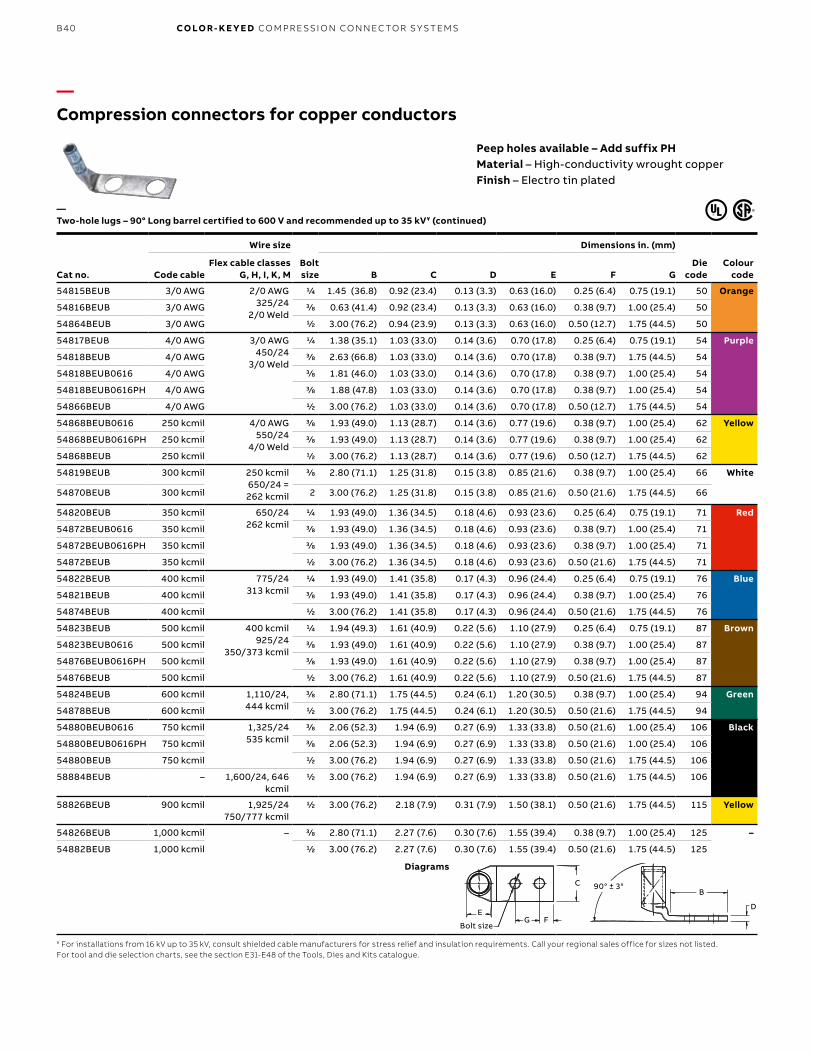
B40 CO LO R- K E Y E D CO M PR E SSI O N CO N N EC TO R S Y S TEMS
—Compression connectors for copper conductors
Peep holes available – Add suffix PHMaterial – High-conductivity wrought copperFinish – Electro tin plated
Cat no.
Wire size
Bolt size
Dimensions in. (mm)
Die code
Colour codeCode cable
Flex cable classes G, H, I, K, M B C D E F G
54815BEUB 3/0 AWG 2/0 AWG325/24
2/0 Weld
1/4 1.45 (36.8) 0.92 (23.4) 0.13 (3.3) 0.63 (16.0) 0.25 (6.4) 0.75 (19.1) 50 Orange
54816BEUB 3/0 AWG 3/8 0.63 (41.4) 0.92 (23.4) 0.13 (3.3) 0.63 (16.0) 0.38 (9.7) 1.00 (25.4) 50
54864BEUB 3/0 AWG 1/2 3.00 (76.2) 0.94 (23.9) 0.13 (3.3) 0.63 (16.0) 0.50 (12.7) 1.75 (44.5) 50
54817BEUB 4/0 AWG 3/0 AWG450/24
3/0 Weld
1/4 1.38 (35.1) 1.03 (33.0) 0.14 (3.6) 0.70 (17.8) 0.25 (6.4) 0.75 (19.1) 54 Purple
54818BEUB 4/0 AWG 3/8 2.63 (66.8) 1.03 (33.0) 0.14 (3.6) 0.70 (17.8) 0.38 (9.7) 1.75 (44.5) 54
54818BEUB0616 4/0 AWG 3/8 1.81 (46.0) 1.03 (33.0) 0.14 (3.6) 0.70 (17.8) 0.38 (9.7) 1.00 (25.4) 54
54818BEUB0616PH 4/0 AWG 3/8 1.88 (47.8) 1.03 (33.0) 0.14 (3.6) 0.70 (17.8) 0.38 (9.7) 1.00 (25.4) 54
54866BEUB 4/0 AWG 1/2 3.00 (76.2) 1.03 (33.0) 0.14 (3.6) 0.70 (17.8) 0.50 (12.7) 1.75 (44.5) 54
54868BEUB0616 250 kcmil 4/0 AWG550/24
4/0 Weld
3/8 1.93 (49.0) 1.13 (28.7) 0.14 (3.6) 0.77 (19.6) 0.38 (9.7) 1.00 (25.4) 62 Yellow
54868BEUB0616PH 250 kcmil 3/8 1.93 (49.0) 1.13 (28.7) 0.14 (3.6) 0.77 (19.6) 0.38 (9.7) 1.00 (25.4) 62
54868BEUB 250 kcmil 1/2 3.00 (76.2) 1.13 (28.7) 0.14 (3.6) 0.77 (19.6) 0.50 (12.7) 1.75 (44.5) 62
54819BEUB 300 kcmil 250 kcmil650/24 = 262 kcmil
3/8 2.80 (71.1) 1.25 (31.8) 0.15 (3.8) 0.85 (21.6) 0.38 (9.7) 1.00 (25.4) 66 White
54870BEUB 300 kcmil 2 3.00 (76.2) 1.25 (31.8) 0.15 (3.8) 0.85 (21.6) 0.50 (21.6) 1.75 (44.5) 66
54820BEUB 350 kcmil 650/24262 kcmil
1/4 1.93 (49.0) 1.36 (34.5) 0.18 (4.6) 0.93 (23.6) 0.25 (6.4) 0.75 (19.1) 71 Red
54872BEUB0616 350 kcmil 3/8 1.93 (49.0) 1.36 (34.5) 0.18 (4.6) 0.93 (23.6) 0.38 (9.7) 1.00 (25.4) 71
54872BEUB0616PH 350 kcmil 3/8 1.93 (49.0) 1.36 (34.5) 0.18 (4.6) 0.93 (23.6) 0.38 (9.7) 1.00 (25.4) 71
54872BEUB 350 kcmil 1/2 3.00 (76.2) 1.36 (34.5) 0.18 (4.6) 0.93 (23.6) 0.50 (21.6) 1.75 (44.5) 71
54822BEUB 400 kcmil 775/24313 kcmil
1/4 1.93 (49.0) 1.41 (35.8) 0.17 (4.3) 0.96 (24.4) 0.25 (6.4) 0.75 (19.1) 76 Blue
54821BEUB 400 kcmil 3/8 1.93 (49.0) 1.41 (35.8) 0.17 (4.3) 0.96 (24.4) 0.38 (9.7) 1.00 (25.4) 76
54874BEUB 400 kcmil 1/2 3.00 (76.2) 1.41 (35.8) 0.17 (4.3) 0.96 (24.4) 0.50 (21.6) 1.75 (44.5) 76
54823BEUB 500 kcmil 400 kcmil925/24
350/373 kcmil
1/4 1.94 (49.3) 1.61 (40.9) 0.22 (5.6) 1.10 (27.9) 0.25 (6.4) 0.75 (19.1) 87 Brown
54823BEUB0616 500 kcmil 3/8 1.93 (49.0) 1.61 (40.9) 0.22 (5.6) 1.10 (27.9) 0.38 (9.7) 1.00 (25.4) 87
54876BEUB0616PH 500 kcmil 3/8 1.93 (49.0) 1.61 (40.9) 0.22 (5.6) 1.10 (27.9) 0.38 (9.7) 1.00 (25.4) 87
54876BEUB 500 kcmil 1/2 3.00 (76.2) 1.61 (40.9) 0.22 (5.6) 1.10 (27.9) 0.50 (21.6) 1.75 (44.5) 87
54824BEUB 600 kcmil 1,110/24, 444 kcmil
3/8 2.80 (71.1) 1.75 (44.5) 0.24 (6.1) 1.20 (30.5) 0.38 (9.7) 1.00 (25.4) 94 Green
54878BEUB 600 kcmil 1/2 3.00 (76.2) 1.75 (44.5) 0.24 (6.1) 1.20 (30.5) 0.50 (21.6) 1.75 (44.5) 94
54880BEUB0616 750 kcmil 1,325/24535 kcmil
3/8 2.06 (52.3) 1.94 (6.9) 0.27 (6.9) 1.33 (33.8) 0.50 (21.6) 1.00 (25.4) 106 Black
54880BEUB0616PH 750 kcmil 3/8 2.06 (52.3) 1.94 (6.9) 0.27 (6.9) 1.33 (33.8) 0.50 (21.6) 1.00 (25.4) 106
54880BEUB 750 kcmil 1/2 3.00 (76.2) 1.94 (6.9) 0.27 (6.9) 1.33 (33.8) 0.50 (21.6) 1.75 (44.5) 106
58884BEUB – 1,600/24, 646 kcmil
1/2 3.00 (76.2) 1.94 (6.9) 0.27 (6.9) 1.33 (33.8) 0.50 (21.6) 1.75 (44.5) 106
58826BEUB 900 kcmil 1,925/24750/777 kcmil
1/2 3.00 (76.2) 2.18 (7.9) 0.31 (7.9) 1.50 (38.1) 0.50 (21.6) 1.75 (44.5) 115 Yellow
54826BEUB 1,000 kcmil – 3/8 2.80 (71.1) 2.27 (7.6) 0.30 (7.6) 1.55 (39.4) 0.38 (9.7) 1.00 (25.4) 125 –
54882BEUB 1,000 kcmil 1/2 3.00 (76.2) 2.27 (7.6) 0.30 (7.6) 1.55 (39.4) 0.50 (21.6) 1.75 (44.5) 125
—Two-hole lugs – 90° Long barrel certified to 600 V and recommended up to 35 kV¥ (continued)
¥ For installations from 16 kV up to 35 kV, consult shielded cable manufacturers for stress relief and insulation requirements. Call your regional sales office for sizes not listed.For tool and die selection charts, see the section E31-E48 of the Tools, Dies and Kits catalogue.
Diagrams
Bolt Size
90° ± 3 °B
D
G F
C
EF
Bolt sizeG
E
CB
D
90° ± 3°
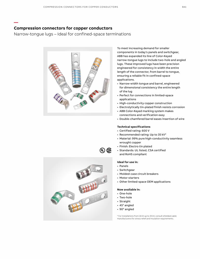
B41
—Compression connectors for copper conductorsNarrow-tongue lugs – Ideal for confined-space terminations
To meet increasing demand for smaller components in today’s panels and switchgear, ABB has expanded its line of Color-Keyed narrow-tongue lugs to include two-hole and angled lugs. These improved lugs have been precision engineered for consistency in width the entire length of the connector, from barrel to tongue, ensuring a reliable fit in confined-space applications.• Narrow-width tongue and barrel, engineered
for dimensional consistency the entire length of the lug
• Perfect for connections in limited-space applications
• High-conductivity copper construction• Electrolytically tin-plated finish resists corrosion• ABB Color-Keyed marking system makes
connections and verification easy • Double-chamfered barrel eases insertion of wire
Technical specifications• Certified rating: 600 V• Recommended rating: Up to 35 kV¥
• Material: 99% pure high-conductivity seamless wrought copper
• Finish: Electro tin plated• Standards: UL listed, CSA certified
and RoHS compliant
Ideal for use in:• Panels• Switchgear• Molded-case circuit breakers• Motor starters• Other limited-space OEM applications
Now available in:• One-hole• Two-hole• Straight• 45° angled• 90° angled
¥ For installations from 16 kV up to 35 kV, consult shielded cable manufacturers for stress relief and insulation requirements.
CO M PR E SSI O N CO N N EC TO R S FO R CO PPER CO N D U C TO R S
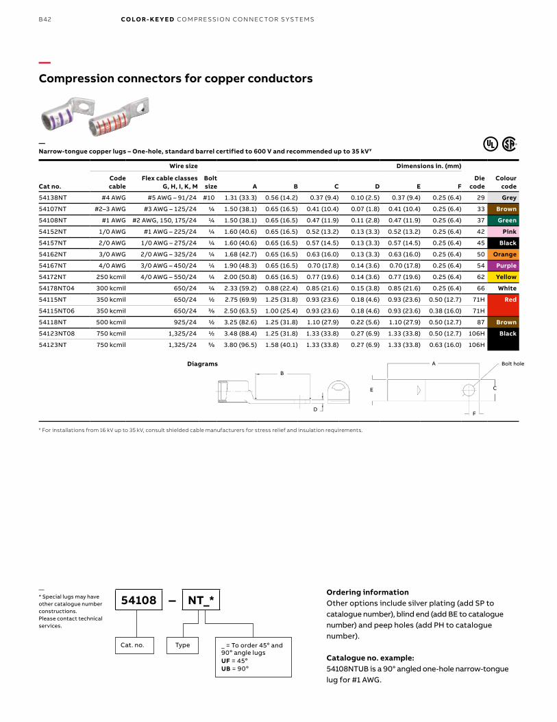
B42 CO LO R- K E Y E D CO M PR E SSI O N CO N N EC TO R S Y S TEMS
Ordering informationOther options include silver plating (add SP to catalogue number), blind end (add BE to catalogue number) and peep holes (add PH to catalogue number).
Catalogue no. example: 54108NTUB is a 90° angled one-hole narrow-tongue lug for #1 AWG.
54108 – NT_*
TypeCat. no. _ = To order 45o and 90o angle lugs UF = 45oUB = 90o
—* Special lugs may have other catalogue number constructions. Please contact technical services.
—Compression connectors for copper conductors
Cat no.
Wire size
Bolt size
Dimensions in. (mm)
Die code
Colour code
Code cable
Flex cable classes G, H, I, K, M A B C D E F
54138NT #4 AWG #5 AWG – 91/24 #10 1.31 (33.3) 0.56 (14.2) 0.37 (9.4) 0.10 (2.5) 0.37 (9.4) 0.25 (6.4) 29 Grey
54107NT #2–3 AWG #3 AWG – 125/24 1/4 1.50 (38.1) 0.65 (16.5) 0.41 (10.4) 0.07 (1.8) 0.41 (10.4) 0.25 (6.4) 33 Brown
54108NT #1 AWG #2 AWG, 150, 175/24 1/4 1.50 (38.1) 0.65 (16.5) 0.47 (11.9) 0.11 (2.8) 0.47 (11.9) 0.25 (6.4) 37 Green
54152NT 1/0 AWG #1 AWG – 225/24 1/4 1.60 (40.6) 0.65 (16.5) 0.52 (13.2) 0.13 (3.3) 0.52 (13.2) 0.25 (6.4) 42 Pink
54157NT 2/0 AWG 1/0 AWG – 275/24 1/4 1.60 (40.6) 0.65 (16.5) 0.57 (14.5) 0.13 (3.3) 0.57 (14.5) 0.25 (6.4) 45 Black
54162NT 3/0 AWG 2/0 AWG – 325/24 1/4 1.68 (42.7) 0.65 (16.5) 0.63 (16.0) 0.13 (3.3) 0.63 (16.0) 0.25 (6.4) 50 Orange
54167NT 4/0 AWG 3/0 AWG – 450/24 1/4 1.90 (48.3) 0.65 (16.5) 0.70 (17.8) 0.14 (3.6) 0.70 (17.8) 0.25 (6.4) 54 Purple
54172NT 250 kcmil 4/0 AWG – 550/24 1/4 2.00 (50.8) 0.65 (16.5) 0.77 (19.6) 0.14 (3.6) 0.77 (19.6) 0.25 (6.4) 62 Yellow
54178NT04 300 kcmil 650/24 1/4 2.33 (59.2) 0.88 (22.4) 0.85 (21.6) 0.15 (3.8) 0.85 (21.6) 0.25 (6.4) 66 White
54115NT 350 kcmil 650/24 1/2 2.75 (69.9) 1.25 (31.8) 0.93 (23.6) 0.18 (4.6) 0.93 (23.6) 0.50 (12.7) 71H Red
54115NT06 350 kcmil 650/24 3/8 2.50 (63.5) 1.00 (25.4) 0.93 (23.6) 0.18 (4.6) 0.93 (23.6) 0.38 (16.0) 71H
54118NT 500 kcmil 925/24 1/2 3.25 (82.6) 1.25 (31.8) 1.10 (27.9) 0.22 (5.6) 1.10 (27.9) 0.50 (12.7) 87 Brown
54123NT08 750 kcmil 1,325/24 1/2 3.48 (88.4) 1.25 (31.8) 1.33 (33.8) 0.27 (6.9) 1.33 (33.8) 0.50 (12.7) 106H Black
54123NT 750 kcmil 1,325/24 5/8 3.80 (96.5) 1.58 (40.1) 1.33 (33.8) 0.27 (6.9) 1.33 (33.8) 0.63 (16.0) 106H
—Narrow-tongue copper lugs – One-hole, standard barrel certified to 600 V and recommended up to 35 kV¥
¥ For installations from 16 kV up to 35 kV, consult shielded cable manufacturers for stress relief and insulation requirements.
H
E
A
F
C
Bolt Hole
B
D
Diagrams
E
A
F
C
Bolt hole
B
D
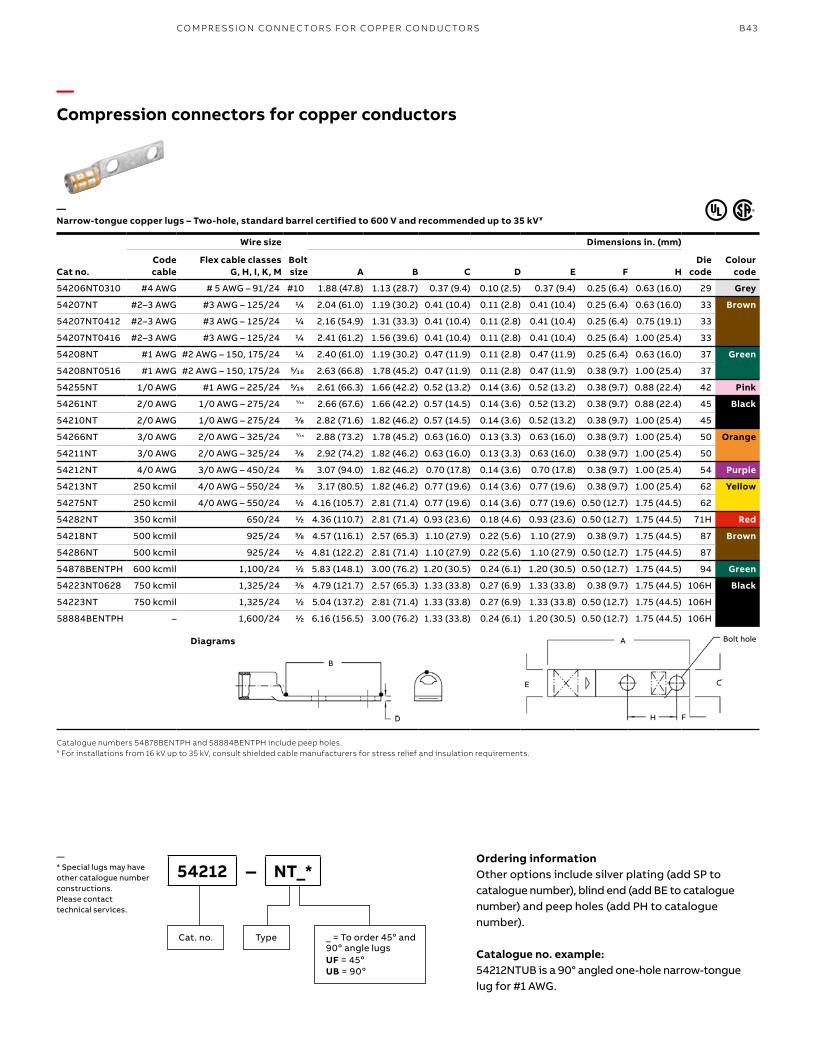
B43
Ordering informationOther options include silver plating (add SP to catalogue number), blind end (add BE to catalogue number) and peep holes (add PH to catalogue number).
Catalogue no. example: 54212NTUB is a 90° angled one-hole narrow-tongue lug for #1 AWG.
54212 – NT_*
TypeCat. no. _ = To order 45o and 90o angle lugs UF = 45oUB = 90o
—* Special lugs may have other catalogue number constructions. Please contact technical services.
Cat no.
Wire size
Bolt size
Dimensions in. (mm)
Die code
Colour code
Code cable
Flex cable classes G, H, I, K, M A B C D E F H
54206NT0310 #4 AWG # 5 AWG – 91/24 #10 1.88 (47.8) 1.13 (28.7) 0.37 (9.4) 0.10 (2.5) 0.37 (9.4) 0.25 (6.4) 0.63 (16.0) 29 Grey
54207NT #2–3 AWG #3 AWG – 125/24 1/4 2.04 (61.0) 1.19 (30.2) 0.41 (10.4) 0.11 (2.8) 0.41 (10.4) 0.25 (6.4) 0.63 (16.0) 33 Brown
54207NT0412 #2–3 AWG #3 AWG – 125/24 1/4 2.16 (54.9) 1.31 (33.3) 0.41 (10.4) 0.11 (2.8) 0.41 (10.4) 0.25 (6.4) 0.75 (19.1) 33
54207NT0416 #2–3 AWG #3 AWG – 125/24 1/4 2.41 (61.2) 1.56 (39.6) 0.41 (10.4) 0.11 (2.8) 0.41 (10.4) 0.25 (6.4) 1.00 (25.4) 33
54208NT #1 AWG #2 AWG – 150, 175/24 1/4 2.40 (61.0) 1.19 (30.2) 0.47 (11.9) 0.11 (2.8) 0.47 (11.9) 0.25 (6.4) 0.63 (16.0) 37 Green
54208NT0516 #1 AWG #2 AWG – 150, 175/24 5⁄16 2.63 (66.8) 1.78 (45.2) 0.47 (11.9) 0.11 (2.8) 0.47 (11.9) 0.38 (9.7) 1.00 (25.4) 37
54255NT 1/0 AWG #1 AWG – 225/24 5⁄16 2.61 (66.3) 1.66 (42.2) 0.52 (13.2) 0.14 (3.6) 0.52 (13.2) 0.38 (9.7) 0.88 (22.4) 42 Pink
54261NT 2/0 AWG 1/0 AWG – 275/24 5⁄16 2.66 (67.6) 1.66 (42.2) 0.57 (14.5) 0.14 (3.6) 0.52 (13.2) 0.38 (9.7) 0.88 (22.4) 45 Black
54210NT 2/0 AWG 1/0 AWG – 275/24 3/8 2.82 (71.6) 1.82 (46.2) 0.57 (14.5) 0.14 (3.6) 0.52 (13.2) 0.38 (9.7) 1.00 (25.4) 45
54266NT 3/0 AWG 2/0 AWG – 325/24 5⁄16 2.88 (73.2) 1.78 (45.2) 0.63 (16.0) 0.13 (3.3) 0.63 (16.0) 0.38 (9.7) 1.00 (25.4) 50 Orange
54211NT 3/0 AWG 2/0 AWG – 325/24 3/8 2.92 (74.2) 1.82 (46.2) 0.63 (16.0) 0.13 (3.3) 0.63 (16.0) 0.38 (9.7) 1.00 (25.4) 50
54212NT 4/0 AWG 3/0 AWG – 450/24 3/8 3.07 (94.0) 1.82 (46.2) 0.70 (17.8) 0.14 (3.6) 0.70 (17.8) 0.38 (9.7) 1.00 (25.4) 54 Purple
54213NT 250 kcmil 4/0 AWG – 550/24 3/8 3.17 (80.5) 1.82 (46.2) 0.77 (19.6) 0.14 (3.6) 0.77 (19.6) 0.38 (9.7) 1.00 (25.4) 62 Yellow
54275NT 250 kcmil 4/0 AWG – 550/24 1/2 4.16 (105.7) 2.81 (71.4) 0.77 (19.6) 0.14 (3.6) 0.77 (19.6) 0.50 (12.7) 1.75 (44.5) 62
54282NT 350 kcmil 650/24 1/2 4.36 (110.7) 2.81 (71.4) 0.93 (23.6) 0.18 (4.6) 0.93 (23.6) 0.50 (12.7) 1.75 (44.5) 71H Red
54218NT 500 kcmil 925/24 3/8 4.57 (116.1) 2.57 (65.3) 1.10 (27.9) 0.22 (5.6) 1.10 (27.9) 0.38 (9.7) 1.75 (44.5) 87 Brown
54286NT 500 kcmil 925/24 1/2 4.81 (122.2) 2.81 (71.4) 1.10 (27.9) 0.22 (5.6) 1.10 (27.9) 0.50 (12.7) 1.75 (44.5) 87
54878BENTPH 600 kcmil 1,100/24 1/2 5.83 (148.1) 3.00 (76.2) 1.20 (30.5) 0.24 (6.1) 1.20 (30.5) 0.50 (12.7) 1.75 (44.5) 94 Green
54223NT0628 750 kcmil 1,325/24 3/8 4.79 (121.7) 2.57 (65.3) 1.33 (33.8) 0.27 (6.9) 1.33 (33.8) 0.38 (9.7) 1.75 (44.5) 106H Black
54223NT 750 kcmil 1,325/24 1/2 5.04 (137.2) 2.81 (71.4) 1.33 (33.8) 0.27 (6.9) 1.33 (33.8) 0.50 (12.7) 1.75 (44.5) 106H
58884BENTPH – 1,600/24 1/2 6.16 (156.5) 3.00 (76.2) 1.33 (33.8) 0.24 (6.1) 1.20 (30.5) 0.50 (12.7) 1.75 (44.5) 106H
Catalogue numbers 54878BENTPH and 58884BENTPH include peep holes.¥ For installations from 16 kV up to 35 kV, consult shielded cable manufacturers for stress relief and insulation requirements.
—Compression connectors for copper conductors
—Narrow-tongue copper lugs – Two-hole, standard barrel certified to 600 V and recommended up to 35 kV¥
Diagrams
E
A
F
C
Bolt hole
B
D H
CO M PR E SSI O N CO N N EC TO R S FO R CO PPER CO N D U C TO R S
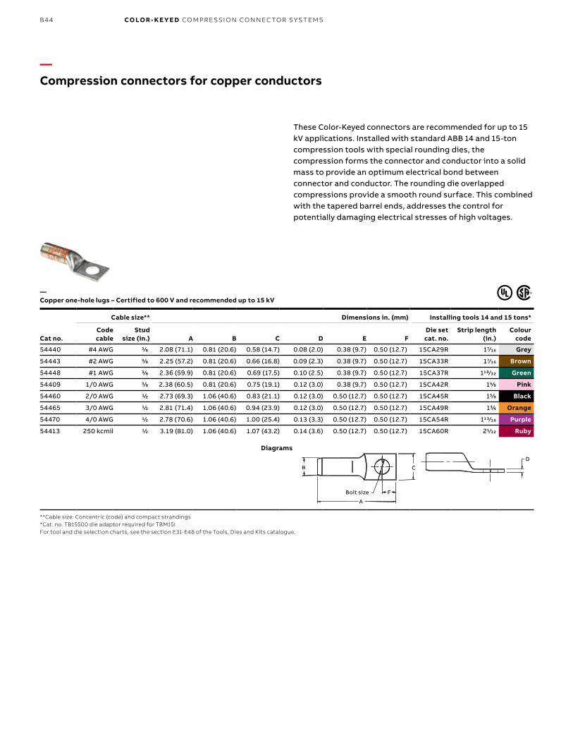
B44 CO LO R- K E Y E D CO M PR E SSI O N CO N N EC TO R S Y S TEMS
—Compression connectors for copper conductors
Cat no.
Cable size** Dimensions in. (mm) Installing tools 14 and 15 tons*
Code cable
Stud size (in.) A B C D E F
Die set cat. no.
Strip length (in.)
Colour code
54440 #4 AWG 3/8 2.08 (71.1) 0.81 (20.6) 0.58 (14.7) 0.08 (2.0) 0.38 (9.7) 0.50 (12.7) 15CA29R 17⁄16 Grey
54443 #2 AWG 3/8 2.25 (57.2) 0.81 (20.6) 0.66 (16.8) 0.09 (2.3) 0.38 (9.7) 0.50 (12.7) 15CA33R 17⁄16 Brown
54448 #1 AWG 3/8 2.36 (59.9) 0.81 (20.6) 0.69 (17.5) 0.10 (2.5) 0.38 (9.7) 0.50 (12.7) 15CA37R 118⁄32 Green
54409 1/0 AWG 3/8 2.38 (60.5) 0.81 (20.6) 0.75 (19.1) 0.12 (3.0) 0.38 (9.7) 0.50 (12.7) 15CA42R 15/8 Pink
54460 2/0 AWG 1/2 2.73 (69.3) 1.06 (40.6) 0.83 (21.1) 0.12 (3.0) 0.50 (12.7) 0.50 (12.7) 15CA45R 15/8 Black
54465 3/0 AWG 1/2 2.81 (71.4) 1.06 (40.6) 0.94 (23.9) 0.12 (3.0) 0.50 (12.7) 0.50 (12.7) 15CA49R 13/4 Orange
54470 4/0 AWG 1/2 2.78 (70.6) 1.06 (40.6) 1.00 (25.4) 0.13 (3.3) 0.50 (12.7) 0.50 (12.7) 15CA54R 113⁄16 Purple
54413 250 kcmil 1/2 3.19 (81.0) 1.06 (40.6) 1.07 (43.2) 0.14 (3.6) 0.50 (12.7) 0.50 (12.7) 15CA60R 21/32 Ruby
—Copper one-hole lugs – Certified to 600 V and recommended up to 15 kV
These Color-Keyed connectors are recommended for up to 15 kV applications. Installed with standard ABB 14 and 15-ton compression tools with special rounding dies, the compression forms the connector and conductor into a solid mass to provide an optimum electrical bond between connector and conductor. The rounding die overlapped compressions provide a smooth round surface. This combined with the tapered barrel ends, addresses the control for potentially damaging electrical stresses of high voltages.
**Cable size: Concentric (code) and compact strandings*Cat. no. TB15500 die adaptor required for TBM15IFor tool and die selection charts, see the section E31-E48 of the Tools, Dies and Kits catalogue.
Diagrams
D
Bolt Size
B
F
C
A
D
C
FBolt size
B
A
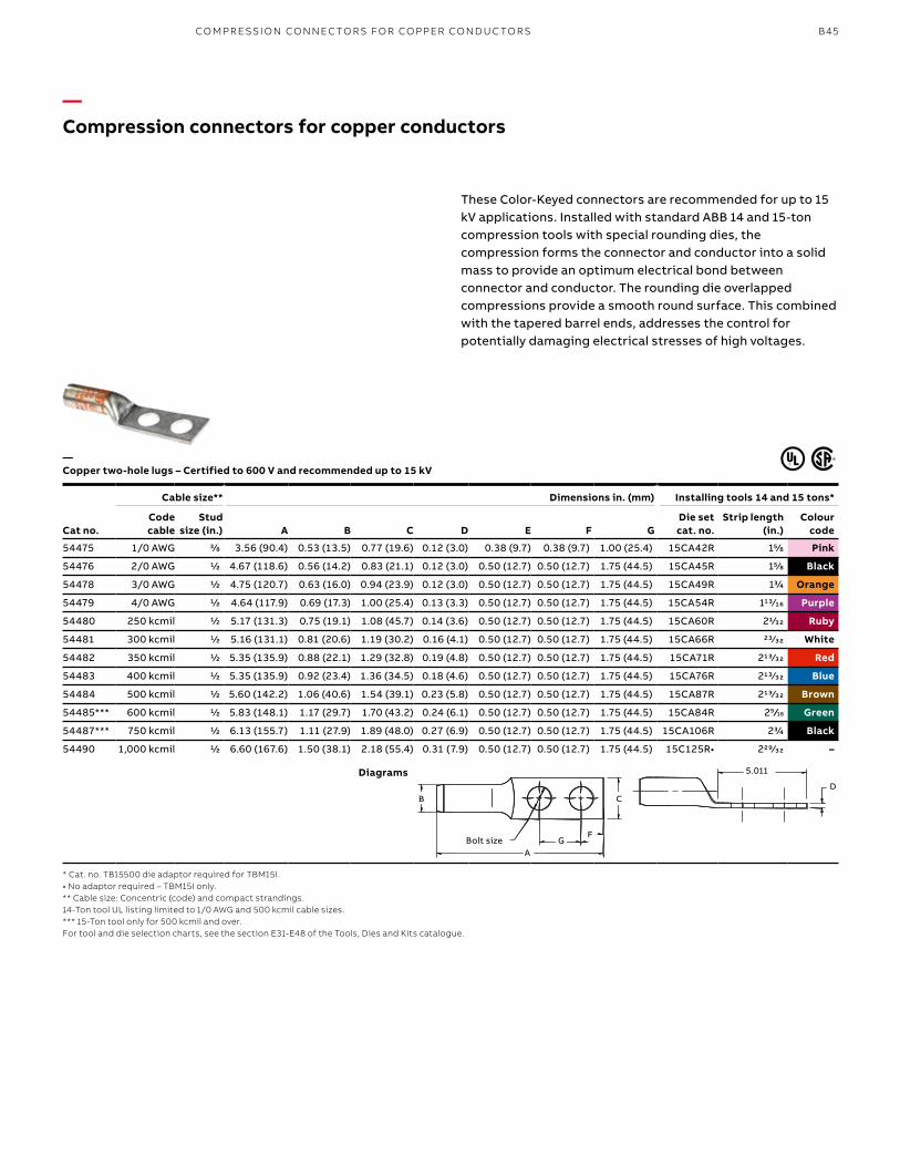
B45
—Compression connectors for copper conductors
Cat no.
Cable size** Dimensions in. (mm) Installing tools 14 and 15 tons*
Code cable
Stud size (in.) A B C D E F G
Die set cat. no.
Strip length (in.)
Colour code
54475 1/0 AWG 3/8 3.56 (90.4) 0.53 (13.5) 0.77 (19.6) 0.12 (3.0) 0.38 (9.7) 0.38 (9.7) 1.00 (25.4) 15CA42R 15/8 Pink
54476 2/0 AWG 1/2 4.67 (118.6) 0.56 (14.2) 0.83 (21.1) 0.12 (3.0) 0.50 (12.7) 0.50 (12.7) 1.75 (44.5) 15CA45R 15/8 Black
54478 3/0 AWG 1/2 4.75 (120.7) 0.63 (16.0) 0.94 (23.9) 0.12 (3.0) 0.50 (12.7) 0.50 (12.7) 1.75 (44.5) 15CA49R 13/4 Orange
54479 4/0 AWG 1/2 4.64 (117.9) 0.69 (17.3) 1.00 (25.4) 0.13 (3.3) 0.50 (12.7) 0.50 (12.7) 1.75 (44.5) 15CA54R 113⁄16 Purple
54480 250 kcmil 1/2 5.17 (131.3) 0.75 (19.1) 1.08 (45.7) 0.14 (3.6) 0.50 (12.7) 0.50 (12.7) 1.75 (44.5) 15CA60R 21/32 Ruby
54481 300 kcmil 1/2 5.16 (131.1) 0.81 (20.6) 1.19 (30.2) 0.16 (4.1) 0.50 (12.7) 0.50 (12.7) 1.75 (44.5) 15CA66R 23⁄32 White
54482 350 kcmil 1/2 5.35 (135.9) 0.88 (22.1) 1.29 (32.8) 0.19 (4.8) 0.50 (12.7) 0.50 (12.7) 1.75 (44.5) 15CA71R 213⁄32 Red
54483 400 kcmil 1/2 5.35 (135.9) 0.92 (23.4) 1.36 (34.5) 0.18 (4.6) 0.50 (12.7) 0.50 (12.7) 1.75 (44.5) 15CA76R 213⁄32 Blue
54484 500 kcmil 1/2 5.60 (142.2) 1.06 (40.6) 1.54 (39.1) 0.23 (5.8) 0.50 (12.7) 0.50 (12.7) 1.75 (44.5) 15CA87R 213⁄32 Brown
54485*** 600 kcmil 1/2 5.83 (148.1) 1.17 (29.7) 1.70 (43.2) 0.24 (6.1) 0.50 (12.7) 0.50 (12.7) 1.75 (44.5) 15CA84R 29 ⁄16 Green
54487*** 750 kcmil 1/2 6.13 (155.7) 1.11 (27.9) 1.89 (48.0) 0.27 (6.9) 0.50 (12.7) 0.50 (12.7) 1.75 (44.5) 15CA106R 23/4 Black
54490 1,000 kcmil 1/2 6.60 (167.6) 1.50 (38.1) 2.18 (55.4) 0.31 (7.9) 0.50 (12.7) 0.50 (12.7) 1.75 (44.5) 15C125R• 229⁄32 –
—Copper two-hole lugs – Certified to 600 V and recommended up to 15 kV
These Color-Keyed connectors are recommended for up to 15 kV applications. Installed with standard ABB 14 and 15-ton compression tools with special rounding dies, the compression forms the connector and conductor into a solid mass to provide an optimum electrical bond between connector and conductor. The rounding die overlapped compressions provide a smooth round surface. This combined with the tapered barrel ends, addresses the control for potentially damaging electrical stresses of high voltages.
* Cat. no. TB15500 die adaptor required for TBM15I.• No adaptor required – TBM15I only.** Cable size: Concentric (code) and compact strandings.14-Ton tool UL listing limited to 1/0 AWG and 500 kcmil cable sizes.*** 15-Ton tool only for 500 kcmil and over.For tool and die selection charts, see the section E31-E48 of the Tools, Dies and Kits catalogue.
Diagrams 5.011
D
GFBolt Size
A
CB
Bolt size
5.011
DC
F
B
AG
CO M PR E SSI O N CO N N EC TO R S FO R CO PPER CO N D U C TO R S
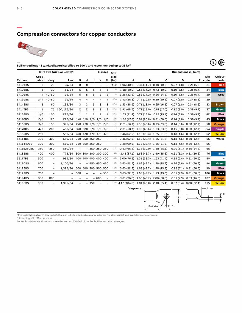
B46 CO LO R- K E Y E D CO M PR E SSI O N CO N N EC TO R S Y S TEMS
Cat. no.
Wire size (AWG or kcmil)* Classes Bolt size (in.)
Dimensions in. (mm)
Die code
Colour code
Code cable Navy Flex G H I K M A B C D F
54104BS 8 23 37/24 8 8 – 8 8 #10 1.06 (40.6) 0.46 (11.7) 0.40 (10.2) 0.07 (1.8) 0.21 (5.3) 21 Red
54105BS 6 30 61/24 5 5 5 5 5 1/4 1.18 (30.0) 0.56 (14.2) 0.43 (10.9) 0.10 (2.5) 0.25 (6.4) 24 Blue
54106BS 4 40–50 91/24 5 5 5 5 5 1/4 1.28 (32.5) 0.56 (14.2) 0.56 (14.2) 0.10 (2.5) 0.25 (6.4) 29 Grey
54139BS 3–4 40–50 91/24 4 4 4 4 4 5/16 1.43 (36.3) 0.78 (19.8) 0.59 (19.8) 0.07 (1.8) 0.34 (8.6) 29
54142BS 2 60 125/24 3 3 3 3 3 5/16 1.53 (38.9) 0.71 (18.0) 0.65 (16.5) 0.07 (1.8) 0.34 (8.6) 33 Brown
54147BS 1 75 150, 175/24 2 2 2 2 2 5/16 1.91 (48.5) 0.71 (18.0) 0.67 (17.0) 0.12 (3.0) 0.38 (9.7) 37 Green
54153BS 1/0 100 225/24 1 1 1 1 1 5/16 1.63 (41.4) 0.71 (18.0) 0.75 (19.1) 0.14 (3.6) 0.38 (9.7) 42 Pink
54110BS 2/0 125 275/24 1/0 1/0 1/0 1/0 1/0 3/8 1.88 (47.8) 0.81 (20.6) 0.81 (20.6) 0.14 (3.6) 0.38 (9.7) 45 Black
54165BS 3/0 150 325/24 2/0 2/0 2/0 2/0 2/0 1/2 2.21 (56.1) 1.06 (40.6) 0.93 (23.6) 0.14 (3.6) 0.50 (12.7) 50 Orange
54170BS 4/0 200 450/24 3/0 3/0 3/0 3/0 3/0 1/2 2.31 (58.7) 1.06 (40.6) 1.03 (33.0) 0.15 (3.8) 0.50 (12.7) 54 Purple
58165BS 250 – 550/24 4/0 4/0 4/0 4/0 4/0 1/2 2.46 (62.5) 1.12 (28.4) 1.25 (31.8) 0.18 (4.6) 0.50 (12.7) 62 Yellow
54114BS 300 300 650/24 250 250 250 250 – 1/2 2.46 (62.5) 1.12 (28.4) 1.25 (31.8) 0.18 (4.6) 0.50 (12.7) 66 White
5411440BS 300 300 650/24 250 250 250 250 – 1/2 2.38 (60.5) 1.12 (28.4) 1.25 (31.8) 0.18 (4.6) 0.50 (12.7) 66
54115260BS 350 350 650/24 – – 250 250 250 1/2 2.63 (66.8) 1.18 (30.0) 1.38 (35.1) 0.20 (5.1) 0.56 (14.2) 66
54185BS 400 400 775/24 300 300 300 300 300 5/8 3.43 (87.1) 1.68 (42.7) 1.40 (35.6) 0.21 (5.3) 0.81 (20.6) 76 Blue
58177BS 500 – 925/24 400 400 400 400 400 5/8 3.00 (76.2) 1.31 (33.3) 1.63 (41.4) 0.25 (6.4) 0.81 (20.6) 80 –
58180BS 600 – 1,100/24 – – 450 450 450 5/8 3.63 (92.2) 1.68 (42.7) 1.78 (45.2) 0.26 (6.6) 0.81 (20.6) 94 Green
54122BS 700 – 1,325/24 500 500 500 500 500 5/8 3.63 (92.2) 1.68 (42.7) 1.78 (45.2) 0.28 (7.1) 0.81 (20.6) 99 Pink
54123BS 750 – – 600 – – – 550 5/8 3.63 (92.2) 1.68 (42.7) 1.93 (49.0) 0.31 (7.9) 0.81 (20.6) 106 Black
54124BS 800 800 – – – – 600 – 5/8 3.81 (96.8) 1.68 (42.7) 2.00 (50.8) 0.31 (7.9) 0.63 (16.0) 107 Orange
54126BS 900 – 1,925/24 – – 750 – – 5/8 4.12 (104.6) 1.81 (46.0) 2.18 (55.4) 0.37 (9.4) 0.88 (22.4) 115 Yellow
—Compression connectors for copper conductors
—Bell-ended lugs – Standard barrel certified to 600 V and recommended up to 35 kV¥
¥ For installations from 16 kV up to 35 kV, consult shielded cable manufacturers for stress relief and insulation requirements.* Stranding will differ per class.For tool and die selection charts, see the section E31-E48 of the Tools, Dies and Kits catalogue.
Bolt Size
B
D
AF
C
Diagrams
C
FBolt sizeA
B
D
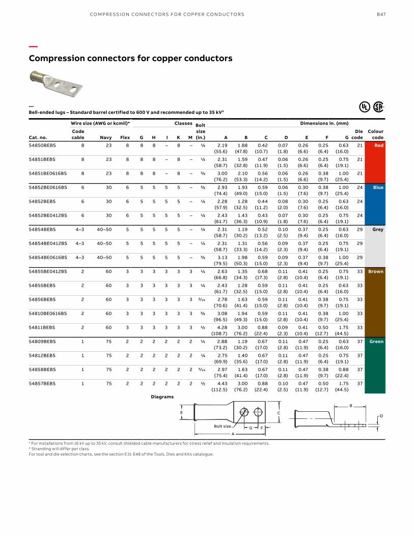
B47
Cat. no.
Wire size (AWG or kcmil)* Classes Bolt size (in.)
Dimensions in. (mm)
Die code
Colour code
Code cable Navy Flex G H I K M A B C D E F G
54850BEBS 8 23 8 8 8 – 8 – 1/4 2.19 (55.6)
1.88 (47.8)
0.42 (10.7)
0.07 (1.8)
0.26 (6.6)
0.25 (6.4)
0.63 (16.0)
21 Red
54851BEBS 8 23 8 8 8 – 8 – 1/4 2.31 (58.7)
1.59 (32.8)
0.47 (11.9)
0.06 (1.5)
0.26 (6.6)
0.25 (6.4)
0.75 (19.1)
21
54851BE0616BS 8 23 8 8 8 – 8 – 3/8 3.00 (76.2)
2.10 (53.3)
0.56 (14.2)
0.06 (1.5)
0.26 (6.6)
0.38 (9.7)
1.00 (25.4)
21
54852BE0616BS 6 30 6 5 5 5 5 – 3/8 2.93 (74.4)
1.93 (49.0)
0.59 (15.0)
0.06 (1.5)
0.30 (7.6)
0.38 (9.7)
1.00 (25.4)
24 Blue
54852BEBS 6 30 6 5 5 5 5 – 1/4 2.28 (57.9)
1.28 (32.5)
0.44 (11.2)
0.08 (2.0)
0.30 (7.6)
0.25 (6.4)
0.63 (16.0)
24
54852BE0412BS 6 30 6 5 5 5 5 – 1/4 2.43 (61.7)
1.43 (36.3)
0.43 (10.9)
0.07 (1.8)
0.30 (7.6)
0.25 (6.4)
0.75 (19.1)
24
54854BEBS 4–3 40–50 5 5 5 5 5 – 1/4 2.31 (58.7)
1.19 (30.2)
0.52 (13.2)
0.10 (2.5)
0.37 (9.4)
0.25 (6.4)
0.63 (16.0)
29 Grey
54854BE0412BS 4–3 40–50 5 5 5 5 5 – 1/4 2.31 (58.7)
1.31 (33.3)
0.56 (14.2)
0.09 (2.3)
0.37 (9.4)
0.25 (6.4)
0.75 (19.1)
29
54854BE0616BS 4–3 40–50 5 5 5 5 5 – 3/8 3.13 (79.5)
1.98 (50.3)
0.59 (15.0)
0.09 (2.3)
0.37 (9.4)
0.38 (9.7)
1.00 (25.4)
29
54855BE0412BS 2 60 3 3 3 3 3 3 1/4 2.63 (66.8)
1.35 (34.3)
0.68 (17.3)
0.11 (2.8)
0.41 (10.4)
0.25 (6.4)
0.75 (19.1)
33 Brown
54855BEBS 2 60 3 3 3 3 3 3 1/4 2.43 (61.7)
1.28 (32.5)
0.59 (15.0)
0.11 (2.8)
0.41 (10.4)
0.25 (6.4)
0.63 (16.0)
33
54856BEBS 2 60 3 3 3 3 3 3 3⁄16 2.78 (70.6)
1.63 (41.4)
0.59 (15.0)
0.11 (2.8)
0.41 (10.4)
0.38 (9.7)
0.75 (19.1)
33
54810BE0616BS 2 60 3 3 3 3 3 3 3/8 3.08 (96.5)
1.94 (49.3)
0.59 (15.0)
0.11 (2.8)
0.41 (10.4)
0.38 (9.7)
1.00 (25.4)
33
54811BEBS 2 60 3 3 3 3 3 3 1/2 4.28 (108.7)
3.00 (76.2)
0.88 (22.4)
0.09 (2.3)
0.41 (10.4)
0.50 (12.7)
1.75 (44.5)
33
54809BEBS 1 75 2 2 2 2 2 2 1/4 2.88 (73.2)
1.19 (30.2)
0.67 (17.0)
0.11 (2.8)
0.47 (11.9)
0.25 (6.4)
0.63 (16.0)
37 Green
54812BEBS 1 75 2 2 2 2 2 2 1/4 2.75 (69.9)
1.40 (35.6)
0.67 (17.0)
0.11 (2.8)
0.47 (11.9)
0.25 (6.4)
0.75 (19.1)
37
54858BEBS 1 75 2 2 2 2 2 2 5⁄16 2.97 (75.4)
1.63 (41.4)
0.67 (17.0)
0.11 (2.8)
0.47 (11.9)
0.38 (9.7)
0.88 (22.4)
37
54857BEBS 1 75 2 2 2 2 2 2 1/2 4.43 (112.5)
3.00 (76.2)
0.88 (22.4)
0.10 (2.5)
0.47 (11.9)
0.50 (12.7)
1.75 (44.5)
37
—Compression connectors for copper conductors
—Bell-ended lugs – Standard barrel certified to 600 V and recommended up to 35 kV¥
¥ For installations from 16 kV up to 35 kV, consult shielded cable manufacturers for stress relief and insulation requirements.* Stranding will differ per class.For tool and die selection charts, see the section E31-E48 of the Tools, Dies and Kits catalogue.
Diagrams B
D
Bolt Size G F
CE
A
B
D
Bolt Size G F
CE
A
B
DE
AG F
C
Bolt size
CO M PR E SSI O N CO N N EC TO R S FO R CO PPER CO N D U C TO R S
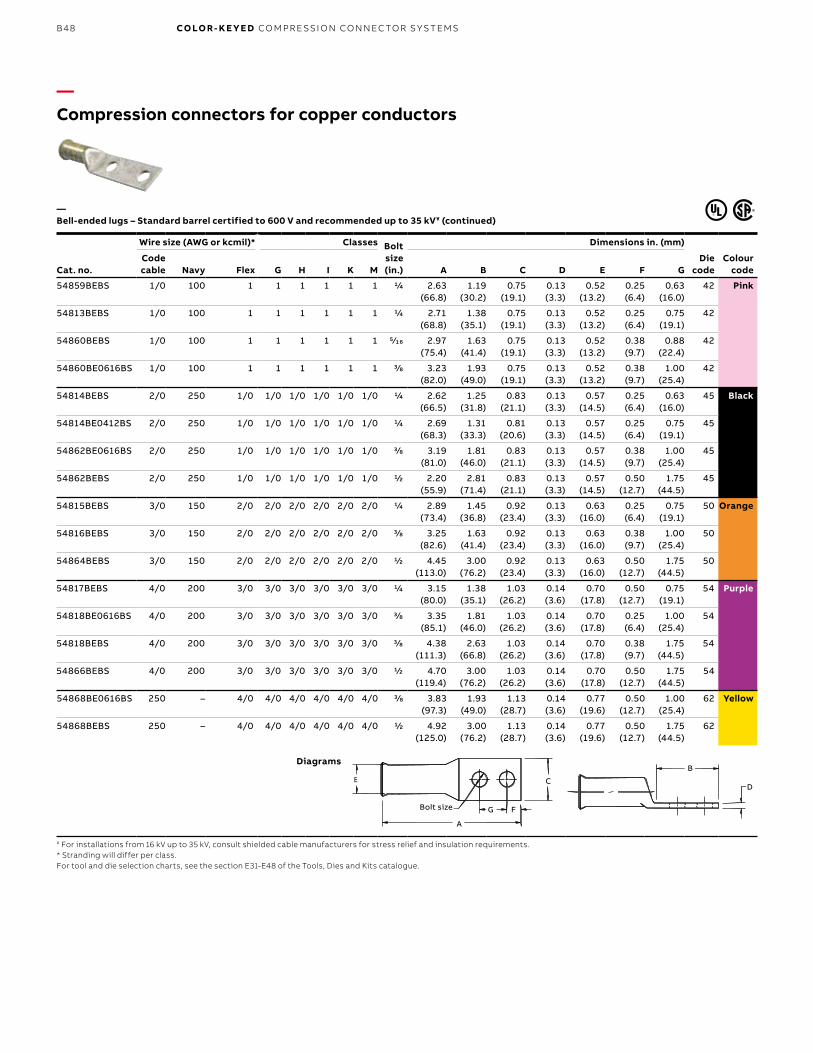
B48 CO LO R- K E Y E D CO M PR E SSI O N CO N N EC TO R S Y S TEMS
Cat. no.
Wire size (AWG or kcmil)* Classes Bolt size (in.)
Dimensions in. (mm)
Die code
Colour code
Code cable Navy Flex G H I K M A B C D E F G
54859BEBS 1/0 100 1 1 1 1 1 1 1/4 2.63 (66.8)
1.19 (30.2)
0.75 (19.1)
0.13 (3.3)
0.52 (13.2)
0.25 (6.4)
0.63 (16.0)
42 Pink
54813BEBS 1/0 100 1 1 1 1 1 1 1/4 2.71 (68.8)
1.38 (35.1)
0.75 (19.1)
0.13 (3.3)
0.52 (13.2)
0.25 (6.4)
0.75 (19.1)
42
54860BEBS 1/0 100 1 1 1 1 1 1 5⁄16 2.97 (75.4)
1.63 (41.4)
0.75 (19.1)
0.13 (3.3)
0.52 (13.2)
0.38 (9.7)
0.88 (22.4)
42
54860BE0616BS 1/0 100 1 1 1 1 1 1 3/8 3.23 (82.0)
1.93 (49.0)
0.75 (19.1)
0.13 (3.3)
0.52 (13.2)
0.38 (9.7)
1.00 (25.4)
42
54814BEBS 2/0 250 1/0 1/0 1/0 1/0 1/0 1/0 1/4 2.62 (66.5)
1.25 (31.8)
0.83 (21.1)
0.13 (3.3)
0.57 (14.5)
0.25 (6.4)
0.63 (16.0)
45 Black
54814BE0412BS 2/0 250 1/0 1/0 1/0 1/0 1/0 1/0 1/4 2.69 (68.3)
1.31 (33.3)
0.81 (20.6)
0.13 (3.3)
0.57 (14.5)
0.25 (6.4)
0.75 (19.1)
45
54862BE0616BS 2/0 250 1/0 1/0 1/0 1/0 1/0 1/0 3/8 3.19 (81.0)
1.81 (46.0)
0.83 (21.1)
0.13 (3.3)
0.57 (14.5)
0.38 (9.7)
1.00 (25.4)
45
54862BEBS 2/0 250 1/0 1/0 1/0 1/0 1/0 1/0 1/2 2.20 (55.9)
2.81 (71.4)
0.83 (21.1)
0.13 (3.3)
0.57 (14.5)
0.50 (12.7)
1.75 (44.5)
45
54815BEBS 3/0 150 2/0 2/0 2/0 2/0 2/0 2/0 1/4 2.89 (73.4)
1.45 (36.8)
0.92 (23.4)
0.13 (3.3)
0.63 (16.0)
0.25 (6.4)
0.75 (19.1)
50 Orange
54816BEBS 3/0 150 2/0 2/0 2/0 2/0 2/0 2/0 3/8 3.25 (82.6)
1.63 (41.4)
0.92 (23.4)
0.13 (3.3)
0.63 (16.0)
0.38 (9.7)
1.00 (25.4)
50
54864BEBS 3/0 150 2/0 2/0 2/0 2/0 2/0 2/0 1/2 4.45 (113.0)
3.00 (76.2)
0.92 (23.4)
0.13 (3.3)
0.63 (16.0)
0.50 (12.7)
1.75 (44.5)
50
54817BEBS 4/0 200 3/0 3/0 3/0 3/0 3/0 3/0 1/4 3.15 (80.0)
1.38 (35.1)
1.03 (26.2)
0.14 (3.6)
0.70 (17.8)
0.50 (12.7)
0.75 (19.1)
54 Purple
54818BE0616BS 4/0 200 3/0 3/0 3/0 3/0 3/0 3/0 3/8 3.35 (85.1)
1.81 (46.0)
1.03 (26.2)
0.14 (3.6)
0.70 (17.8)
0.25 (6.4)
1.00 (25.4)
54
54818BEBS 4/0 200 3/0 3/0 3/0 3/0 3/0 3/0 3/8 4.38 (111.3)
2.63 (66.8)
1.03 (26.2)
0.14 (3.6)
0.70 (17.8)
0.38 (9.7)
1.75 (44.5)
54
54866BEBS 4/0 200 3/0 3/0 3/0 3/0 3/0 3/0 1/2 4.70 (119.4)
3.00 (76.2)
1.03 (26.2)
0.14 (3.6)
0.70 (17.8)
0.50 (12.7)
1.75 (44.5)
54
54868BE0616BS 250 – 4/0 4/0 4/0 4/0 4/0 4/0 3/8 3.83 (97.3)
1.93 (49.0)
1.13 (28.7)
0.14 (3.6)
0.77 (19.6)
0.50 (12.7)
1.00 (25.4)
62 Yellow
54868BEBS 250 – 4/0 4/0 4/0 4/0 4/0 4/0 1/2 4.92 (125.0)
3.00 (76.2)
1.13 (28.7)
0.14 (3.6)
0.77 (19.6)
0.50 (12.7)
1.75 (44.5)
62
—Compression connectors for copper conductors
—Bell-ended lugs – Standard barrel certified to 600 V and recommended up to 35 kV¥ (continued)
¥ For installations from 16 kV up to 35 kV, consult shielded cable manufacturers for stress relief and insulation requirements.* Stranding will differ per class.For tool and die selection charts, see the section E31-E48 of the Tools, Dies and Kits catalogue.
Diagrams
B
D
Bolt Size G F
CE
A
B
D
Bolt Size G F
CE
A
B
D
A
G F
C
Bolt size
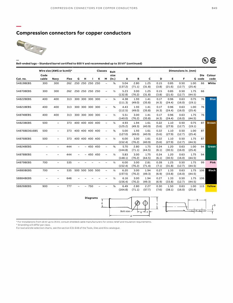
B49
Cat. no.
Wire size (AWG or kcmil)* Classes Bolt size (in.)
Dimensions in. (mm)
Die code
Colour code
Code cable Navy Flex G H I K M A B C D E F G
54819BEBS 300 300 262 250 250 250 250 – 3⁄8 5.04 (137.2)
2.80 (71.1)
1.25 (31.8)
0.15 (3.8)
0.85 (21.6)
0.50 (12.7)
1.00 (25.4)
66 White
54870BEBS 300 300 262 250 250 250 250 – 1⁄2 5.23 (132.8)
3.00 (76.2)
1.25 (31.8)
0.15 (3.8)
0.85 (21.6)
0.50 (12.7)
1.75 (44.5)
66
54822BEBS 400 400 313 300 300 300 300 – 1⁄4 4.38 (111.3)
1.93 (49.0)
1.41 (35.8)
0.17 (4.3)
0.96 (24.4)
0.63 (16.0)
0.75 (19.1)
76 Blue
54821BEBS 400 400 313 300 300 300 300 – 3⁄8 4.43 (112.5)
1.93 (49.0)
1.41 (35.8)
0.17 (4.3)
0.96 (24.4)
0.63 (16.0)
1.00 (25.4)
76
54874BEBS 400 400 313 300 300 300 300 – 1⁄2 5.51 (140.0)
3.00 (76.2)
1.41 (35.8)
0.17 (4.3)
0.96 (24.4)
0.63 (16.0)
1.75 (44.5)
76
54823BEBS 500 – 373 400 400 400 400 – 1⁄4 4.93 (125.2)
1.94 (49.3)
1.61 (40.9)
0.22 (5.6)
1.10 (27.9)
0.50 (12.7)
0.75 (19.1)
87 Brown
54876BE0616BS 500 – 373 400 400 400 400 – 3⁄8 5.00 (127.0)
1.93 (49.0)
1.61 (40.9)
0.22 (5.6)
1.10 (27.9)
0.50 (12.7)
1.00 (25.4)
87
54876BEBS 500 – 373 400 400 400 400 – 1⁄2 6.00 (152.4)
3.00 (76.2)
1.61 (40.9)
0.22 (5.6)
1.10 (27.9)
0.50 (12.7)
1.75 (44.5)
87
54824BEBS – – 444 – – 450 450 – 3⁄8 5.70 (144.8)
2.80 (71.1)
1.75 (44.5)
0.24 (6.1)
1.20 (30.5)
0.63 (16.0)
1.00 (25.4)
94 Green
54878BEBS – – 444 – – 450 450 – 1⁄2 5.83 (148.1)
3.00 (76.2)
1.75 (44.5)
0.24 (6.1)
1.20 (30.5)
0.63 (16.0)
1.75 (44.5)
94
54879BEBS 700 – 535 – – – – – 1⁄2 6.00 (152.4)
3.00 (76.2)
2.81 (71.4)
0.28 (7.1)
1.25 (31.8)
0.50 (12.7)
1.75 (44.5)
99 Pink
54880BEBS 700 – 535 500 500 500 500 – 1⁄2 6.20 (157.5)
3.00 (76.2)
1.94 (49.3)
0.27 (6.9)
1.33 (33.8)
0.63 (16.0)
1.75 (44.5)
106 Black
58884BEBS – – 646 – – – – – 1⁄2 6.16 (156.4)
3.00 (76.2)
1.94 (49.3)
0.27 (6.9)
1.33 (33.8)
0.50 (12.7)
1.75 (44.5)
106
58826BEBS 900 – 777 – – 750 – – 3⁄8 6.49 (164.8)
2.80 (71.1)
2.27 (57.7)
0.30 (7.6)
1.50 (38.1)
0.63 (16.0)
1.00 (25.4)
115 Yellow
—Compression connectors for copper conductors
—Bell-ended lugs – Standard barrel certified to 600 V and recommended up to 35 kV¥ (continued)
¥ For installations from 16 kV up to 35 kV, consult shielded cable manufacturers for stress relief and insulation requirements.* Stranding will differ per class.For tool and die selection charts, see the section E31-E48 of the Tools, Dies and Kits catalogue.
Diagrams
B
D
Bolt Size G F
CE
A
B
D
Bolt Size G F
CE
A
B
DE
A
G F
C
Bolt size
CO M PR E SSI O N CO N N EC TO R S FO R CO PPER CO N D U C TO R S
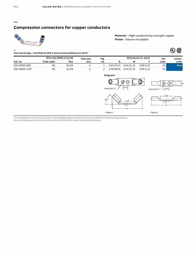
B50 CO LO R- K E Y E D CO M PR E SSI O N CO N N EC TO R S Y S TEMS
—Compression connectors for copper conductors
—Two-barrel lugs – Certified to 600 V and recommended up to 35 kV¥
¥ For installations from 16 kV up to 35 kV, consult shielded cable manufacturers for stress relief and insulation requirements.For tool and die selection charts, see the section E31-E48 of the Tools, Dies and Kits catalogue.
Cat. no.
Wire size (AWG or kcmil) Hole size (in.)
Fig.no.
Dimensions in. (mm) Diecode
Colour codeCode cable Flex A W T
256-30695-828 #6 61/24 1⁄4 1 2.94 (74.7) 0.44 (11.2) 0.06 (1.5) 24 Blue
256-30695-1227 #6 61/24 1⁄4 2 3.38 (85.9) 0.44 (11.2) 0.06 (1.5) 24
Figure 2
1.50
TA
W
Hole size 1⁄4" 0.75
Figure 1
60°1.50
TA
Hole size 1⁄4"0.75
W
Diagrams
Material – High-conductivity wrought copperFinish – Electro tin plated
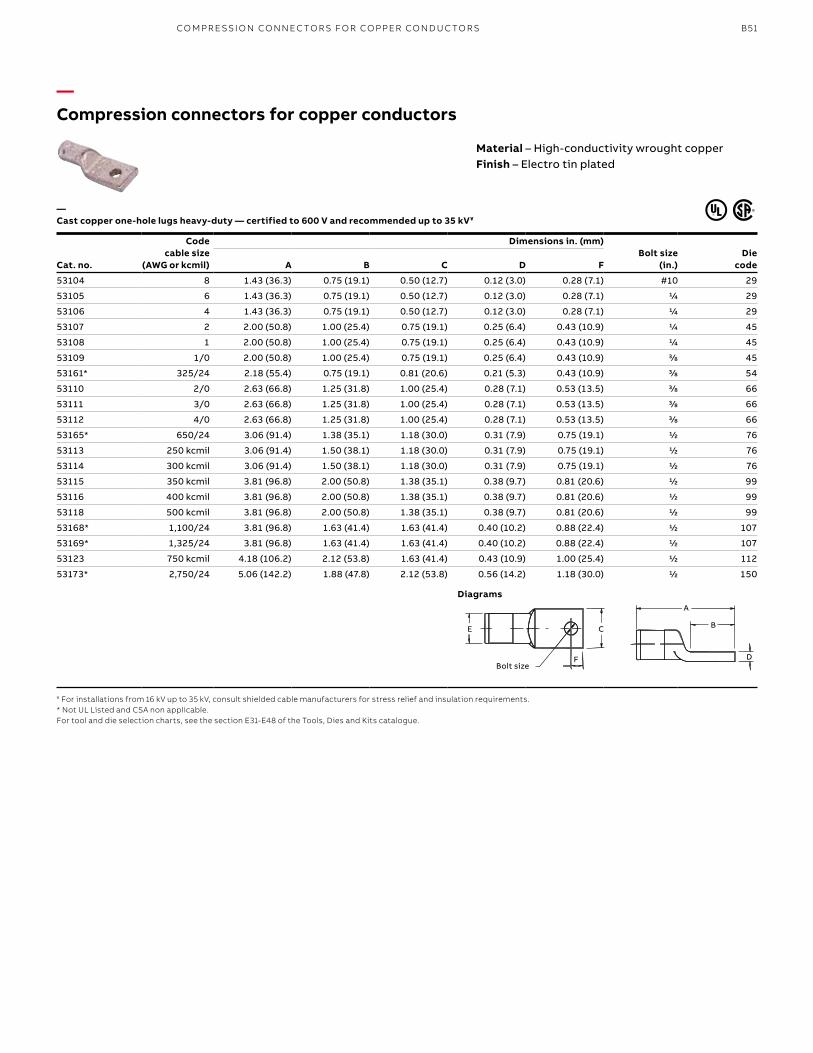
B51
—Compression connectors for copper conductors
—Cast copper one-hole lugs heavy-duty — certified to 600 V and recommended up to 35 kV¥
Material – High-conductivity wrought copperFinish – Electro tin plated
Cat. no.
Code cable size
(AWG or kcmil)
Dimensions in. (mm)Bolt size
(in.)Die
codeA B C D F
53104 8 1.43 (36.3) 0.75 (19.1) 0.50 (12.7) 0.12 (3.0) 0.28 (7.1) #10 29
53105 6 1.43 (36.3) 0.75 (19.1) 0.50 (12.7) 0.12 (3.0) 0.28 (7.1) 1/4 29
53106 4 1.43 (36.3) 0.75 (19.1) 0.50 (12.7) 0.12 (3.0) 0.28 (7.1) 1/4 29
53107 2 2.00 (50.8) 1.00 (25.4) 0.75 (19.1) 0.25 (6.4) 0.43 (10.9) 1/4 45
53108 1 2.00 (50.8) 1.00 (25.4) 0.75 (19.1) 0.25 (6.4) 0.43 (10.9) 1/4 45
53109 1/0 2.00 (50.8) 1.00 (25.4) 0.75 (19.1) 0.25 (6.4) 0.43 (10.9) 3/8 45
53161* 325/24 2.18 (55.4) 0.75 (19.1) 0.81 (20.6) 0.21 (5.3) 0.43 (10.9) 3/8 54
53110 2/0 2.63 (66.8) 1.25 (31.8) 1.00 (25.4) 0.28 (7.1) 0.53 (13.5) 3/8 66
53111 3/0 2.63 (66.8) 1.25 (31.8) 1.00 (25.4) 0.28 (7.1) 0.53 (13.5) 3/8 66
53112 4/0 2.63 (66.8) 1.25 (31.8) 1.00 (25.4) 0.28 (7.1) 0.53 (13.5) 3/8 66
53165* 650/24 3.06 (91.4) 1.38 (35.1) 1.18 (30.0) 0.31 (7.9) 0.75 (19.1) 1/2 76
53113 250 kcmil 3.06 (91.4) 1.50 (38.1) 1.18 (30.0) 0.31 (7.9) 0.75 (19.1) 1/2 76
53114 300 kcmil 3.06 (91.4) 1.50 (38.1) 1.18 (30.0) 0.31 (7.9) 0.75 (19.1) 1/2 76
53115 350 kcmil 3.81 (96.8) 2.00 (50.8) 1.38 (35.1) 0.38 (9.7) 0.81 (20.6) 1/2 99
53116 400 kcmil 3.81 (96.8) 2.00 (50.8) 1.38 (35.1) 0.38 (9.7) 0.81 (20.6) 1/2 99
53118 500 kcmil 3.81 (96.8) 2.00 (50.8) 1.38 (35.1) 0.38 (9.7) 0.81 (20.6) 1/2 99
53168* 1,100/24 3.81 (96.8) 1.63 (41.4) 1.63 (41.4) 0.40 (10.2) 0.88 (22.4) 1/2 107
53169* 1,325/24 3.81 (96.8) 1.63 (41.4) 1.63 (41.4) 0.40 (10.2) 0.88 (22.4) 1/2 107
53123 750 kcmil 4.18 (106.2) 2.12 (53.8) 1.63 (41.4) 0.43 (10.9) 1.00 (25.4) 1/2 112
53173* 2,750/24 5.06 (142.2) 1.88 (47.8) 2.12 (53.8) 0.56 (14.2) 1.18 (30.0) 1/2 150
Bolt size
E C
F
A
B
D
Diagrams
¥ For installations from 16 kV up to 35 kV, consult shielded cable manufacturers for stress relief and insulation requirements.* Not UL Listed and CSA non applicable.For tool and die selection charts, see the section E31-E48 of the Tools, Dies and Kits catalogue.
CO M PR E SSI O N CO N N EC TO R S FO R CO PPER CO N D U C TO R S
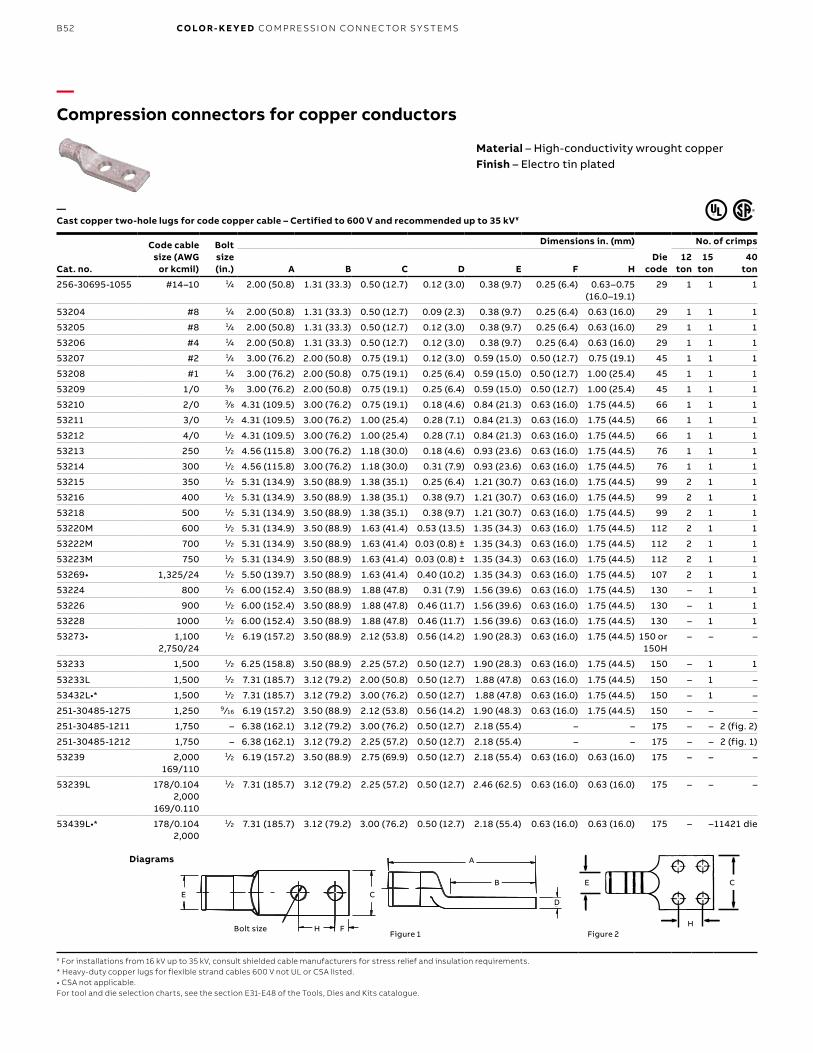
B52 CO LO R- K E Y E D CO M PR E SSI O N CO N N EC TO R S Y S TEMS
Cat. no.
Code cable size (AWG
or kcmil)
Bolt size (in.)
Dimensions in. (mm)
Diecode
No. of crimps
A B C D E F H12
ton15
ton40
ton
256-30695-1055 #14–10 1⁄4 2.00 (50.8) 1.31 (33.3) 0.50 (12.7) 0.12 (3.0) 0.38 (9.7) 0.25 (6.4) 0.63–0.75 (16.0–19.1)
29 1 1 1
53204 #8 1⁄4 2.00 (50.8) 1.31 (33.3) 0.50 (12.7) 0.09 (2.3) 0.38 (9.7) 0.25 (6.4) 0.63 (16.0) 29 1 1 1
53205 #8 1⁄4 2.00 (50.8) 1.31 (33.3) 0.50 (12.7) 0.12 (3.0) 0.38 (9.7) 0.25 (6.4) 0.63 (16.0) 29 1 1 1
53206 #4 1⁄4 2.00 (50.8) 1.31 (33.3) 0.50 (12.7) 0.12 (3.0) 0.38 (9.7) 0.25 (6.4) 0.63 (16.0) 29 1 1 1
53207 #2 1⁄4 3.00 (76.2) 2.00 (50.8) 0.75 (19.1) 0.12 (3.0) 0.59 (15.0) 0.50 (12.7) 0.75 (19.1) 45 1 1 1
53208 #1 1⁄4 3.00 (76.2) 2.00 (50.8) 0.75 (19.1) 0.25 (6.4) 0.59 (15.0) 0.50 (12.7) 1.00 (25.4) 45 1 1 1
53209 1/0 3⁄8 3.00 (76.2) 2.00 (50.8) 0.75 (19.1) 0.25 (6.4) 0.59 (15.0) 0.50 (12.7) 1.00 (25.4) 45 1 1 1
53210 2/0 3⁄8 4.31 (109.5) 3.00 (76.2) 0.75 (19.1) 0.18 (4.6) 0.84 (21.3) 0.63 (16.0) 1.75 (44.5) 66 1 1 1
53211 3/0 1⁄2 4.31 (109.5) 3.00 (76.2) 1.00 (25.4) 0.28 (7.1) 0.84 (21.3) 0.63 (16.0) 1.75 (44.5) 66 1 1 1
53212 4/0 1⁄2 4.31 (109.5) 3.00 (76.2) 1.00 (25.4) 0.28 (7.1) 0.84 (21.3) 0.63 (16.0) 1.75 (44.5) 66 1 1 1
53213 250 1⁄2 4.56 (115.8) 3.00 (76.2) 1.18 (30.0) 0.18 (4.6) 0.93 (23.6) 0.63 (16.0) 1.75 (44.5) 76 1 1 1
53214 300 1⁄2 4.56 (115.8) 3.00 (76.2) 1.18 (30.0) 0.31 (7.9) 0.93 (23.6) 0.63 (16.0) 1.75 (44.5) 76 1 1 1
53215 350 1⁄2 5.31 (134.9) 3.50 (88.9) 1.38 (35.1) 0.25 (6.4) 1.21 (30.7) 0.63 (16.0) 1.75 (44.5) 99 2 1 1
53216 400 1⁄2 5.31 (134.9) 3.50 (88.9) 1.38 (35.1) 0.38 (9.7) 1.21 (30.7) 0.63 (16.0) 1.75 (44.5) 99 2 1 1
53218 500 1⁄2 5.31 (134.9) 3.50 (88.9) 1.38 (35.1) 0.38 (9.7) 1.21 (30.7) 0.63 (16.0) 1.75 (44.5) 99 2 1 1
53220M 600 1⁄2 5.31 (134.9) 3.50 (88.9) 1.63 (41.4) 0.53 (13.5) 1.35 (34.3) 0.63 (16.0) 1.75 (44.5) 112 2 1 1
53222M 700 1⁄2 5.31 (134.9) 3.50 (88.9) 1.63 (41.4) 0.03 (0.8) ± 1.35 (34.3) 0.63 (16.0) 1.75 (44.5) 112 2 1 1
53223M 750 1⁄2 5.31 (134.9) 3.50 (88.9) 1.63 (41.4) 0.03 (0.8) ± 1.35 (34.3) 0.63 (16.0) 1.75 (44.5) 112 2 1 1
53269• 1,325/24 1⁄2 5.50 (139.7) 3.50 (88.9) 1.63 (41.4) 0.40 (10.2) 1.35 (34.3) 0.63 (16.0) 1.75 (44.5) 107 2 1 1
53224 800 1⁄2 6.00 (152.4) 3.50 (88.9) 1.88 (47.8) 0.31 (7.9) 1.56 (39.6) 0.63 (16.0) 1.75 (44.5) 130 – 1 1
53226 900 1⁄2 6.00 (152.4) 3.50 (88.9) 1.88 (47.8) 0.46 (11.7) 1.56 (39.6) 0.63 (16.0) 1.75 (44.5) 130 – 1 1
53228 1000 1⁄2 6.00 (152.4) 3.50 (88.9) 1.88 (47.8) 0.46 (11.7) 1.56 (39.6) 0.63 (16.0) 1.75 (44.5) 130 – 1 1
53273• 1,100 2,750/24
1⁄2 6.19 (157.2) 3.50 (88.9) 2.12 (53.8) 0.56 (14.2) 1.90 (28.3) 0.63 (16.0) 1.75 (44.5) 150 or 150H
– – –
53233 1,500 1⁄2 6.25 (158.8) 3.50 (88.9) 2.25 (57.2) 0.50 (12.7) 1.90 (28.3) 0.63 (16.0) 1.75 (44.5) 150 – 1 1
53233L 1,500 1⁄2 7.31 (185.7) 3.12 (79.2) 2.00 (50.8) 0.50 (12.7) 1.88 (47.8) 0.63 (16.0) 1.75 (44.5) 150 – 1 –
53432L•* 1,500 1⁄2 7.31 (185.7) 3.12 (79.2) 3.00 (76.2) 0.50 (12.7) 1.88 (47.8) 0.63 (16.0) 1.75 (44.5) 150 – 1 –
251-30485-1275 1,250 9 ⁄16 6.19 (157.2) 3.50 (88.9) 2.12 (53.8) 0.56 (14.2) 1.90 (48.3) 0.63 (16.0) 1.75 (44.5) 150 – – –
251-30485-1211 1,750 – 6.38 (162.1) 3.12 (79.2) 3.00 (76.2) 0.50 (12.7) 2.18 (55.4) – – 175 – – 2 (fig. 2)
251-30485-1212 1,750 – 6.38 (162.1) 3.12 (79.2) 2.25 (57.2) 0.50 (12.7) 2.18 (55.4) – – 175 – – 2 (fig. 1)
53239 2,000 169/110
1⁄2 6.19 (157.2) 3.50 (88.9) 2.75 (69.9) 0.50 (12.7) 2.18 (55.4) 0.63 (16.0) 0.63 (16.0) 175 – – –
53239L 178/0.104 2,000
169/0.110
1⁄2 7.31 (185.7) 3.12 (79.2) 2.25 (57.2) 0.50 (12.7) 2.46 (62.5) 0.63 (16.0) 0.63 (16.0) 175 – – –
53439L•* 178/0.104 2,000
1⁄2 7.31 (185.7) 3.12 (79.2) 3.00 (76.2) 0.50 (12.7) 2.18 (55.4) 0.63 (16.0) 0.63 (16.0) 175 – –11421 die
—Compression connectors for copper conductors
—Cast copper two-hole lugs for code copper cable – Certified to 600 V and recommended up to 35 kV¥
¥ For installations from 16 kV up to 35 kV, consult shielded cable manufacturers for stress relief and insulation requirements.* Heavy-duty copper lugs for flexible strand cables 600 V not UL or CSA listed.• CSA not applicable.For tool and die selection charts, see the section E31-E48 of the Tools, Dies and Kits catalogue.
Material – High-conductivity wrought copperFinish – Electro tin plated
Bolt Size
D
B
A
E
H F
C
E C
H
Figure 1
Figure 2
Bolt Size
D
B
A
E
H F
C
E C
H
Figure 1
Figure 2
Diagrams
FH
CE
Bolt sizeFigure 1
A
B
D
C
H
E
Figure 2
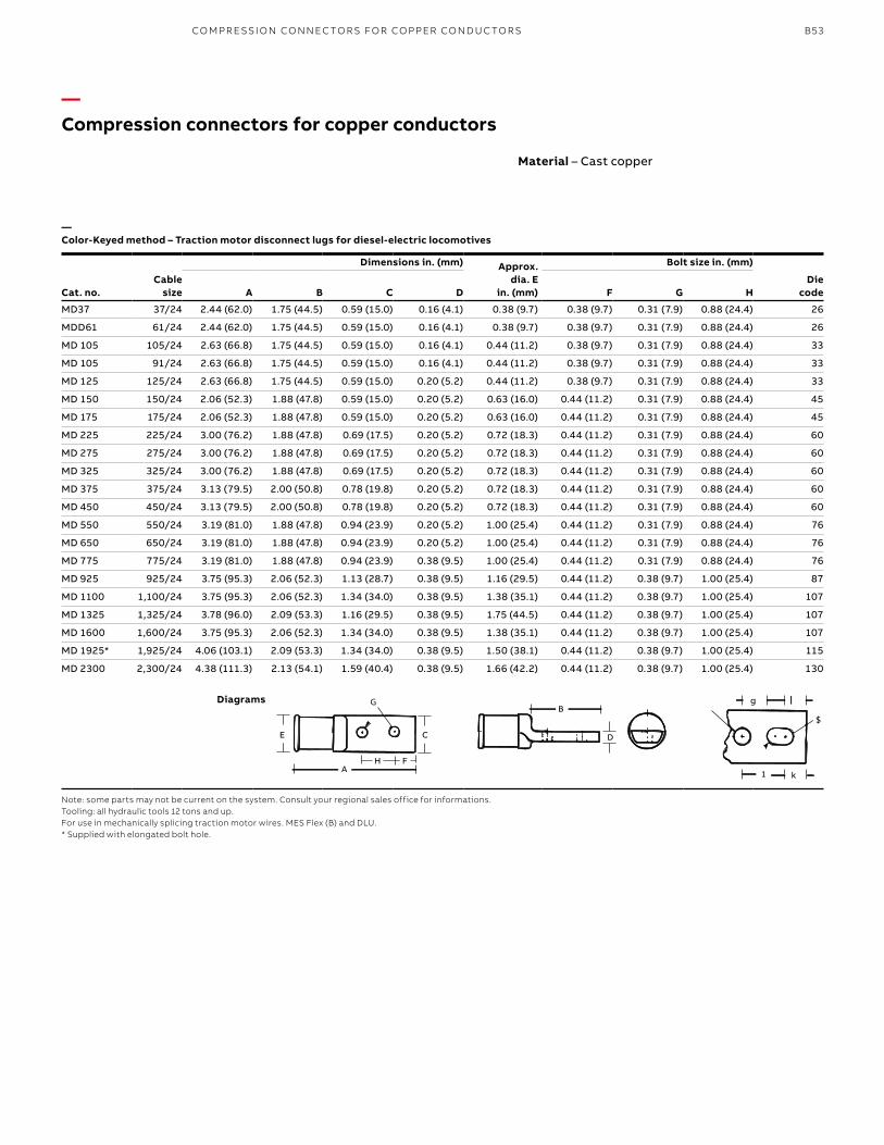
B53
Cat. no.Cable
size
Dimensions in. (mm) Approx. dia. E
in. (mm)
Bolt size in. (mm)
A B C D F G HDie
code
MD37 37/24 2.44 (62.0) 1.75 (44.5) 0.59 (15.0) 0.16 (4.1) 0.38 (9.7) 0.38 (9.7) 0.31 (7.9) 0.88 (24.4) 26
MDD61 61/24 2.44 (62.0) 1.75 (44.5) 0.59 (15.0) 0.16 (4.1) 0.38 (9.7) 0.38 (9.7) 0.31 (7.9) 0.88 (24.4) 26
MD 105 105/24 2.63 (66.8) 1.75 (44.5) 0.59 (15.0) 0.16 (4.1) 0.44 (11.2) 0.38 (9.7) 0.31 (7.9) 0.88 (24.4) 33
MD 105 91/24 2.63 (66.8) 1.75 (44.5) 0.59 (15.0) 0.16 (4.1) 0.44 (11.2) 0.38 (9.7) 0.31 (7.9) 0.88 (24.4) 33
MD 125 125/24 2.63 (66.8) 1.75 (44.5) 0.59 (15.0) 0.20 (5.2) 0.44 (11.2) 0.38 (9.7) 0.31 (7.9) 0.88 (24.4) 33
MD 150 150/24 2.06 (52.3) 1.88 (47.8) 0.59 (15.0) 0.20 (5.2) 0.63 (16.0) 0.44 (11.2) 0.31 (7.9) 0.88 (24.4) 45
MD 175 175/24 2.06 (52.3) 1.88 (47.8) 0.59 (15.0) 0.20 (5.2) 0.63 (16.0) 0.44 (11.2) 0.31 (7.9) 0.88 (24.4) 45
MD 225 225/24 3.00 (76.2) 1.88 (47.8) 0.69 (17.5) 0.20 (5.2) 0.72 (18.3) 0.44 (11.2) 0.31 (7.9) 0.88 (24.4) 60
MD 275 275/24 3.00 (76.2) 1.88 (47.8) 0.69 (17.5) 0.20 (5.2) 0.72 (18.3) 0.44 (11.2) 0.31 (7.9) 0.88 (24.4) 60
MD 325 325/24 3.00 (76.2) 1.88 (47.8) 0.69 (17.5) 0.20 (5.2) 0.72 (18.3) 0.44 (11.2) 0.31 (7.9) 0.88 (24.4) 60
MD 375 375/24 3.13 (79.5) 2.00 (50.8) 0.78 (19.8) 0.20 (5.2) 0.72 (18.3) 0.44 (11.2) 0.31 (7.9) 0.88 (24.4) 60
MD 450 450/24 3.13 (79.5) 2.00 (50.8) 0.78 (19.8) 0.20 (5.2) 0.72 (18.3) 0.44 (11.2) 0.31 (7.9) 0.88 (24.4) 60
MD 550 550/24 3.19 (81.0) 1.88 (47.8) 0.94 (23.9) 0.20 (5.2) 1.00 (25.4) 0.44 (11.2) 0.31 (7.9) 0.88 (24.4) 76
MD 650 650/24 3.19 (81.0) 1.88 (47.8) 0.94 (23.9) 0.20 (5.2) 1.00 (25.4) 0.44 (11.2) 0.31 (7.9) 0.88 (24.4) 76
MD 775 775/24 3.19 (81.0) 1.88 (47.8) 0.94 (23.9) 0.38 (9.5) 1.00 (25.4) 0.44 (11.2) 0.31 (7.9) 0.88 (24.4) 76
MD 925 925/24 3.75 (95.3) 2.06 (52.3) 1.13 (28.7) 0.38 (9.5) 1.16 (29.5) 0.44 (11.2) 0.38 (9.7) 1.00 (25.4) 87
MD 1100 1,100/24 3.75 (95.3) 2.06 (52.3) 1.34 (34.0) 0.38 (9.5) 1.38 (35.1) 0.44 (11.2) 0.38 (9.7) 1.00 (25.4) 107
MD 1325 1,325/24 3.78 (96.0) 2.09 (53.3) 1.16 (29.5) 0.38 (9.5) 1.75 (44.5) 0.44 (11.2) 0.38 (9.7) 1.00 (25.4) 107
MD 1600 1,600/24 3.75 (95.3) 2.06 (52.3) 1.34 (34.0) 0.38 (9.5) 1.38 (35.1) 0.44 (11.2) 0.38 (9.7) 1.00 (25.4) 107
MD 1925* 1,925/24 4.06 (103.1) 2.09 (53.3) 1.34 (34.0) 0.38 (9.5) 1.50 (38.1) 0.44 (11.2) 0.38 (9.7) 1.00 (25.4) 115
MD 2300 2,300/24 4.38 (111.3) 2.13 (54.1) 1.59 (40.4) 0.38 (9.5) 1.66 (42.2) 0.44 (11.2) 0.38 (9.7) 1.00 (25.4) 130
—Compression connectors for copper conductors
—Color-Keyed method – Traction motor disconnect lugs for diesel-electric locomotives
Note: some parts may not be current on the system. Consult your regional sales office for informations.Tooling: all hydraulic tools 12 tons and up.For use in mechanically splicing traction motor wires. MES Flex (B) and DLU.* Supplied with elongated bolt hole.
Material – Cast copper
G
CE
H FA
B
D
g l
k
$
G
CE
H FA
B
D
g l
k
$
G
CE
H FA
B
D
g l
k
$
Diagrams
FH
C
A
B
D
g
E
$
1 k
CO M PR E SSI O N CO N N EC TO R S FO R CO PPER CO N D U C TO R S
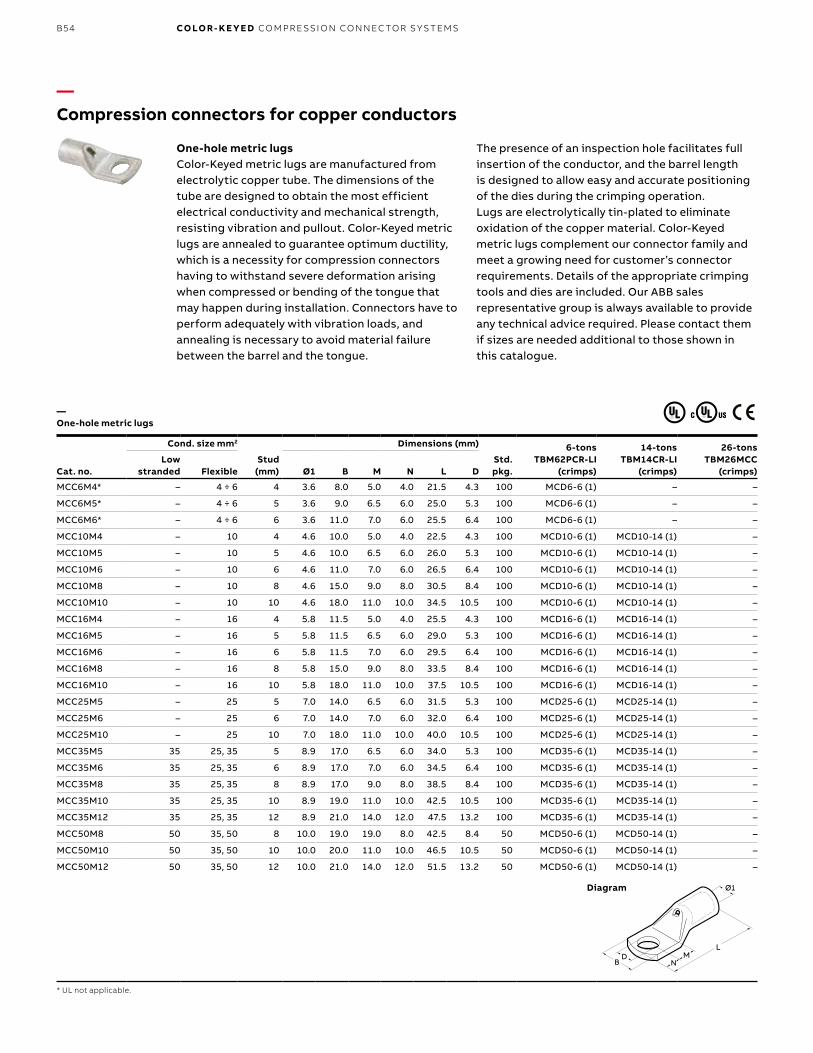
B54 CO LO R- K E Y E D CO M PR E SSI O N CO N N EC TO R S Y S TEMS
Cat. no.
Cond. size mm2
Stud (mm)
Dimensions (mm)
Std. pkg.
6-tons TBM62PCR-LI
(crimps)
14-tons TBM14CR-LI
(crimps)
26-tons TBM26MCC
(crimps)Low
stranded Flexible Ø1 B M N L D
MCC6M4* – 4 ÷ 6 4 3.6 8.0 5.0 4.0 21.5 4.3 100 MCD6-6 (1) – –
MCC6M5* – 4 ÷ 6 5 3.6 9.0 6.5 6.0 25.0 5.3 100 MCD6-6 (1) – –
MCC6M6* – 4 ÷ 6 6 3.6 11.0 7.0 6.0 25.5 6.4 100 MCD6-6 (1) – –
MCC10M4 – 10 4 4.6 10.0 5.0 4.0 22.5 4.3 100 MCD10-6 (1) MCD10-14 (1) –
MCC10M5 – 10 5 4.6 10.0 6.5 6.0 26.0 5.3 100 MCD10-6 (1) MCD10-14 (1) –
MCC10M6 – 10 6 4.6 11.0 7.0 6.0 26.5 6.4 100 MCD10-6 (1) MCD10-14 (1) –
MCC10M8 – 10 8 4.6 15.0 9.0 8.0 30.5 8.4 100 MCD10-6 (1) MCD10-14 (1) –
MCC10M10 – 10 10 4.6 18.0 11.0 10.0 34.5 10.5 100 MCD10-6 (1) MCD10-14 (1) –
MCC16M4 – 16 4 5.8 11.5 5.0 4.0 25.5 4.3 100 MCD16-6 (1) MCD16-14 (1) –
MCC16M5 – 16 5 5.8 11.5 6.5 6.0 29.0 5.3 100 MCD16-6 (1) MCD16-14 (1) –
MCC16M6 – 16 6 5.8 11.5 7.0 6.0 29.5 6.4 100 MCD16-6 (1) MCD16-14 (1) –
MCC16M8 – 16 8 5.8 15.0 9.0 8.0 33.5 8.4 100 MCD16-6 (1) MCD16-14 (1) –
MCC16M10 – 16 10 5.8 18.0 11.0 10.0 37.5 10.5 100 MCD16-6 (1) MCD16-14 (1) –
MCC25M5 – 25 5 7.0 14.0 6.5 6.0 31.5 5.3 100 MCD25-6 (1) MCD25-14 (1) –
MCC25M6 – 25 6 7.0 14.0 7.0 6.0 32.0 6.4 100 MCD25-6 (1) MCD25-14 (1) –
MCC25M10 – 25 10 7.0 18.0 11.0 10.0 40.0 10.5 100 MCD25-6 (1) MCD25-14 (1) –
MCC35M5 35 25, 35 5 8.9 17.0 6.5 6.0 34.0 5.3 100 MCD35-6 (1) MCD35-14 (1) –
MCC35M6 35 25, 35 6 8.9 17.0 7.0 6.0 34.5 6.4 100 MCD35-6 (1) MCD35-14 (1) –
MCC35M8 35 25, 35 8 8.9 17.0 9.0 8.0 38.5 8.4 100 MCD35-6 (1) MCD35-14 (1) –
MCC35M10 35 25, 35 10 8.9 19.0 11.0 10.0 42.5 10.5 100 MCD35-6 (1) MCD35-14 (1) –
MCC35M12 35 25, 35 12 8.9 21.0 14.0 12.0 47.5 13.2 100 MCD35-6 (1) MCD35-14 (1) –
MCC50M8 50 35, 50 8 10.0 19.0 19.0 8.0 42.5 8.4 50 MCD50-6 (1) MCD50-14 (1) –
MCC50M10 50 35, 50 10 10.0 20.0 11.0 10.0 46.5 10.5 50 MCD50-6 (1) MCD50-14 (1) –
MCC50M12 50 35, 50 12 10.0 21.0 14.0 12.0 51.5 13.2 50 MCD50-6 (1) MCD50-14 (1) –
—Compression connectors for copper conductors
—One-hole metric lugs
* UL not applicable.
Diagram
One-hole metric lugsColor-Keyed metric lugs are manufactured from electrolytic copper tube. The dimensions of the tube are designed to obtain the most efficient electrical conductivity and mechanical strength, resisting vibration and pullout. Color-Keyed metric lugs are annealed to guarantee optimum ductility, which is a necessity for compression connectors having to withstand severe deformation arising when compressed or bending of the tongue that may happen during installation. Connectors have to perform adequately with vibration loads, and annealing is necessary to avoid material failure between the barrel and the tongue.
The presence of an inspection hole facilitates full insertion of the conductor, and the barrel length is designed to allow easy and accurate positioning of the dies during the crimping operation.Lugs are electrolytically tin-plated to eliminate oxidation of the copper material. Color-Keyed metric lugs complement our connector family and meet a growing need for customer’s connector requirements. Details of the appropriate crimping tools and dies are included. Our ABB sales representative group is always available to provide any technical advice required. Please contact them if sizes are needed additional to those shown in this catalogue.
1Ø1
LM
ND
B
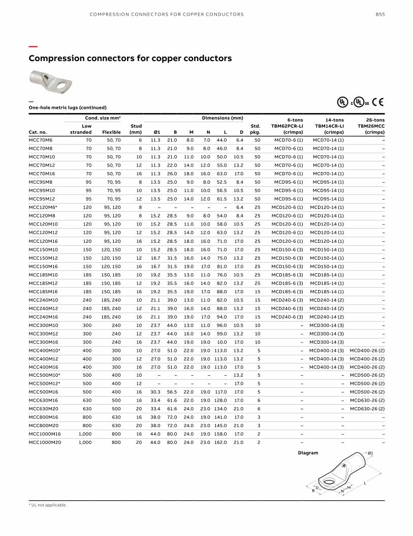
B55
Cat. no.
Cond. size mm2
Stud (mm)
Dimensions (mm)
Std. pkg.
6-tons TBM62PCR-LI
(crimps)
14-tons TBM14CR-LI
(crimps)
26-tons TBM26MCC
(crimps)Low
stranded Flexible Ø1 B M N L D
MCC70M6 70 50, 70 6 11.3 21.0 8.0 7.0 44.0 6.4 50 MCD70-6 (1) MCD70-14 (1) –
MCC70M8 70 50, 70 8 11.3 21.0 9.0 8.0 46.0 8.4 50 MCD70-6 (1) MCD70-14 (1) –
MCC70M10 70 50, 70 10 11.3 21.0 11.0 10.0 50.0 10.5 50 MCD70-6 (1) MCD70-14 (1) –
MCC70M12 70 50, 70 12 11.3 22.0 14.0 12.0 55.0 13.2 50 MCD70-6 (1) MCD70-14 (1) –
MCC70M16 70 50, 70 16 11.3 26.0 18.0 16.0 63.0 17.0 50 MCD70-6 (1) MCD70-14 (1) –
MCC95M8 95 70, 95 8 13.5 25.0 9.0 8.0 52.5 8.4 50 MCD95-6 (1) MCD95-14 (1) –
MCC95M10 95 70, 95 10 13.5 25.0 11.0 10.0 56.5 10.5 50 MCD95-6 (1) MCD95-14 (1) –
MCC95M12 95 70, 95 12 13.5 25.0 14.0 12.0 61.5 13.2 50 MCD95-6 (1) MCD95-14 (1) –
MCC120M6* 120 95, 120 8 – – – – – 6.4 25 MCD120-6 (1) MCD120-14 (1) –
MCC120M8 120 95, 120 8 15.2 28.5 9.0 8.0 54.0 8.4 25 MCD120-6 (1) MCD120-14 (1) –
MCC120M10 120 95, 120 10 15.2 28.5 11.0 10.0 58.0 10.5 25 MCD120-6 (1) MCD120-14 (1) –
MCC120M12 120 95, 120 12 15.2 28.5 14.0 12.0 63.0 13.2 25 MCD120-6 (1) MCD120-14 (1) –
MCC120M16 120 95, 120 16 15.2 28.5 18.0 16.0 71.0 17.0 25 MCD120-6 (1) MCD120-14 (1) –
MCC150M10 150 120, 150 10 15.2 28.5 18.0 16.0 71.0 17.0 25 MCD150-6 (3) MCD150-14 (1) –
MCC150M12 150 120, 150 12 16.7 31.5 16.0 14.0 75.0 13.2 25 MCD150-6 (3) MCD150-14 (1) –
MCC150M16 150 120, 150 16 16.7 31.5 19.0 17.0 81.0 17.0 25 MCD150-6 (3) MCD150-14 (1) –
MCC185M10 185 150, 185 10 19.2 35.5 13.0 11.0 76.0 10.5 25 MCD185-6 (3) MCD185-14 (1) –
MCC185M12 185 150, 185 12 19.2 35.5 16.0 14.0 82.0 13.2 25 MCD185-6 (3) MCD185-14 (1) –
MCC185M16 185 150, 185 16 19.2 35.5 19.0 17.0 88.0 17.0 15 MCD185-6 (3) MCD185-14 (1) –
MCC240M10 240 185, 240 10 21.1 39.0 13.0 11.0 82.0 10.5 15 MCD240-6 (3) MCD240-14 (2) –
MCC240M12 240 185, 240 12 21.1 39.0 16.0 14.0 88.0 13.2 15 MCD240-6 (3) MCD240-14 (2) –
MCC240M16 240 185, 240 16 21.1 39.0 19.0 17.0 94.0 17.0 15 MCD240-6 (3) MCD240-14 (2) –
MCC300M10 300 240 10 23.7 44.0 13.0 11.0 96.0 10.5 10 – MCD300-14 (3) –
MCC300M12 300 240 12 23.7 44.0 16.0 14.0 99.0 13.2 10 – MCD300-14 (3) –
MCC300M16 300 240 16 23.7 44.0 19.0 19.0 10.0 17.0 10 – MCD300-14 (3) –
MCC400M10* 400 300 10 27.0 51.0 22.0 19.0 113.0 13.2 5 – MCD400-14 (3) MCD400-26 (2)
MCC400M12 400 300 12 27.0 51.0 22.0 19.0 113.0 13.2 5 – MCD400-14 (3) MCD400-26 (2)
MCC400M16 400 300 16 27.0 51.0 22.0 19.0 113.0 17.0 5 – MCD400-14 (3) MCD400-26 (2)
MCC500M10* 500 400 10 – – – – – 13.2 5 – – MCD500-26 (2)
MCC500M12* 500 400 12 – – – – – 17.0 5 – – MCD500-26 (2)
MCC500M16 500 400 16 30.3 56.5 22.0 19.0 117.0 17.0 5 – – MCD500-26 (2)
MCC630M16 630 500 16 33.4 61.6 22.0 19.0 128.0 17.0 6 – – MCD630-26 (2)
MCC630M20 630 500 20 33.4 61.6 24.0 23.0 134.0 21.0 6 – – MCD630-26 (2)
MCC800M16 800 630 16 38.0 72.0 24.0 19.0 141.0 17.0 3 – – –
MCC800M20 800 630 20 38.0 72.0 24.0 23.0 145.0 21.0 3 – – –
MCC1000M16 1,000 800 16 44.0 80.0 24.0 19.0 158.0 17.0 2 – – –
MCC1000M20 1,000 800 20 44.0 80.0 24.0 23.0 162.0 21.0 2 – – –
—Compression connectors for copper conductors
—One-hole metric lugs (continued)
* UL not applicable.
Diagram 1Ø1
LM
ND
B
CO M PR E SSI O N CO N N EC TO R S FO R CO PPER CO N D U C TO R S
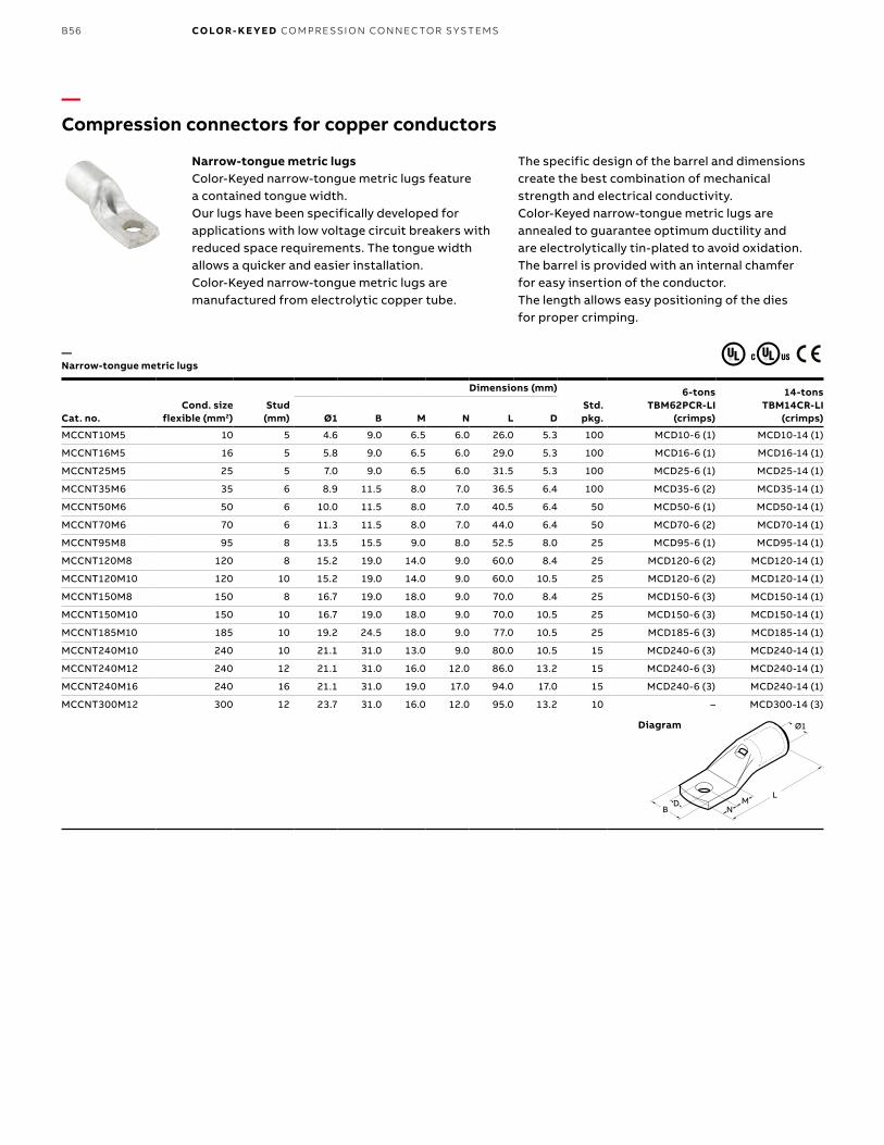
B56 CO LO R- K E Y E D CO M PR E SSI O N CO N N EC TO R S Y S TEMS
Cat. no.Cond. size
flexible (mm2)Stud
(mm)
Dimensions (mm)
Std. pkg.
6-tons TBM62PCR-LI
(crimps)
14-tons TBM14CR-LI
(crimps)Ø1 B M N L D
MCCNT10M5 10 5 4.6 9.0 6.5 6.0 26.0 5.3 100 MCD10-6 (1) MCD10-14 (1)
MCCNT16M5 16 5 5.8 9.0 6.5 6.0 29.0 5.3 100 MCD16-6 (1) MCD16-14 (1)
MCCNT25M5 25 5 7.0 9.0 6.5 6.0 31.5 5.3 100 MCD25-6 (1) MCD25-14 (1)
MCCNT35M6 35 6 8.9 11.5 8.0 7.0 36.5 6.4 100 MCD35-6 (2) MCD35-14 (1)
MCCNT50M6 50 6 10.0 11.5 8.0 7.0 40.5 6.4 50 MCD50-6 (1) MCD50-14 (1)
MCCNT70M6 70 6 11.3 11.5 8.0 7.0 44.0 6.4 50 MCD70-6 (2) MCD70-14 (1)
MCCNT95M8 95 8 13.5 15.5 9.0 8.0 52.5 8.0 25 MCD95-6 (1) MCD95-14 (1)
MCCNT120M8 120 8 15.2 19.0 14.0 9.0 60.0 8.4 25 MCD120-6 (2) MCD120-14 (1)
MCCNT120M10 120 10 15.2 19.0 14.0 9.0 60.0 10.5 25 MCD120-6 (2) MCD120-14 (1)
MCCNT150M8 150 8 16.7 19.0 18.0 9.0 70.0 8.4 25 MCD150-6 (3) MCD150-14 (1)
MCCNT150M10 150 10 16.7 19.0 18.0 9.0 70.0 10.5 25 MCD150-6 (3) MCD150-14 (1)
MCCNT185M10 185 10 19.2 24.5 18.0 9.0 77.0 10.5 25 MCD185-6 (3) MCD185-14 (1)
MCCNT240M10 240 10 21.1 31.0 13.0 9.0 80.0 10.5 15 MCD240-6 (3) MCD240-14 (1)
MCCNT240M12 240 12 21.1 31.0 16.0 12.0 86.0 13.2 15 MCD240-6 (3) MCD240-14 (1)
MCCNT240M16 240 16 21.1 31.0 19.0 17.0 94.0 17.0 15 MCD240-6 (3) MCD240-14 (1)
MCCNT300M12 300 12 23.7 31.0 16.0 12.0 95.0 13.2 10 – MCD300-14 (3)
—Compression connectors for copper conductors
—Narrow-tongue metric lugs
Diagram
Narrow-tongue metric lugsColor-Keyed narrow-tongue metric lugs feature a contained tongue width.Our lugs have been specifically developed for applications with low voltage circuit breakers with reduced space requirements. The tongue width allows a quicker and easier installation. Color-Keyed narrow-tongue metric lugs are manufactured from electrolytic copper tube.
The specific design of the barrel and dimensions create the best combination of mechanical strength and electrical conductivity.Color-Keyed narrow-tongue metric lugs are annealed to guarantee optimum ductility and are electrolytically tin-plated to avoid oxidation.The barrel is provided with an internal chamfer for easy insertion of the conductor. The length allows easy positioning of the dies for proper crimping.
1Ø1
LM
ND
B
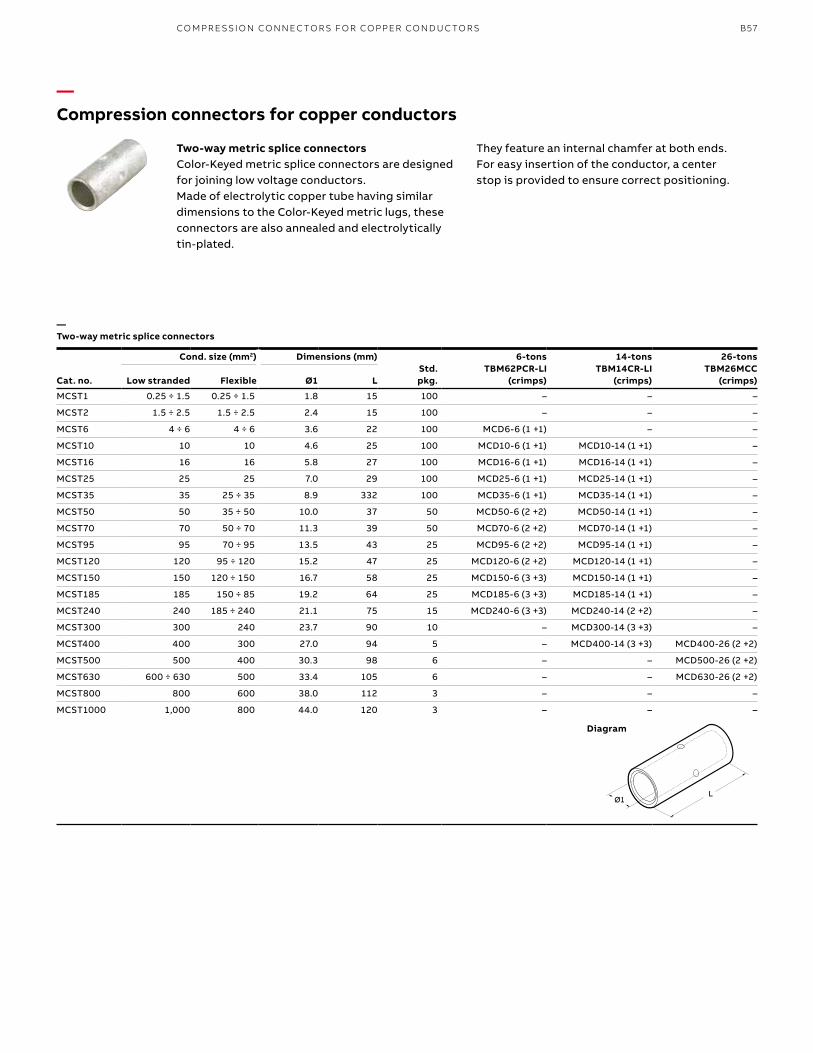
B57
Cat. no.
Cond. size (mm2) Dimensions (mm)Std. pkg.
6-tons TBM62PCR-LI
(crimps)
14-tons TBM14CR-LI
(crimps)
26-tons TBM26MCC
(crimps)Low stranded Flexible Ø1 L
MCST1 0.25 ÷ 1.5 0.25 ÷ 1.5 1.8 15 100 – – –
MCST2 1.5 ÷ 2.5 1.5 ÷ 2.5 2.4 15 100 – – –
MCST6 4 ÷ 6 4 ÷ 6 3.6 22 100 MCD6-6 (1 +1) – –
MCST10 10 10 4.6 25 100 MCD10-6 (1 +1) MCD10-14 (1 +1) –
MCST16 16 16 5.8 27 100 MCD16-6 (1 +1) MCD16-14 (1 +1) –
MCST25 25 25 7.0 29 100 MCD25-6 (1 +1) MCD25-14 (1 +1) –
MCST35 35 25 ÷ 35 8.9 332 100 MCD35-6 (1 +1) MCD35-14 (1 +1) –
MCST50 50 35 ÷ 50 10.0 37 50 MCD50-6 (2 +2) MCD50-14 (1 +1) –
MCST70 70 50 ÷ 70 11.3 39 50 MCD70-6 (2 +2) MCD70-14 (1 +1) –
MCST95 95 70 ÷ 95 13.5 43 25 MCD95-6 (2 +2) MCD95-14 (1 +1) –
MCST120 120 95 ÷ 120 15.2 47 25 MCD120-6 (2 +2) MCD120-14 (1 +1) –
MCST150 150 120 ÷ 150 16.7 58 25 MCD150-6 (3 +3) MCD150-14 (1 +1) –
MCST185 185 150 ÷ 85 19.2 64 25 MCD185-6 (3 +3) MCD185-14 (1 +1) –
MCST240 240 185 ÷ 240 21.1 75 15 MCD240-6 (3 +3) MCD240-14 (2 +2) –
MCST300 300 240 23.7 90 10 – MCD300-14 (3 +3) –
MCST400 400 300 27.0 94 5 – MCD400-14 (3 +3) MCD400-26 (2 +2)
MCST500 500 400 30.3 98 6 – – MCD500-26 (2 +2)
MCST630 600 ÷ 630 500 33.4 105 6 – – MCD630-26 (2 +2)
MCST800 800 600 38.0 112 3 – – –
MCST1000 1,000 800 44.0 120 3 – – –
—Compression connectors for copper conductors
—Two-way metric splice connectors
Diagram
Two-way metric splice connectorsColor-Keyed metric splice connectors are designed for joining low voltage conductors.Made of electrolytic copper tube having similar dimensions to the Color-Keyed metric lugs, these connectors are also annealed and electrolytically tin-plated.
They feature an internal chamfer at both ends. For easy insertion of the conductor, a center stop is provided to ensure correct positioning.
Ø1L
CO M PR E SSI O N CO N N EC TO R S FO R CO PPER CO N D U C TO R S
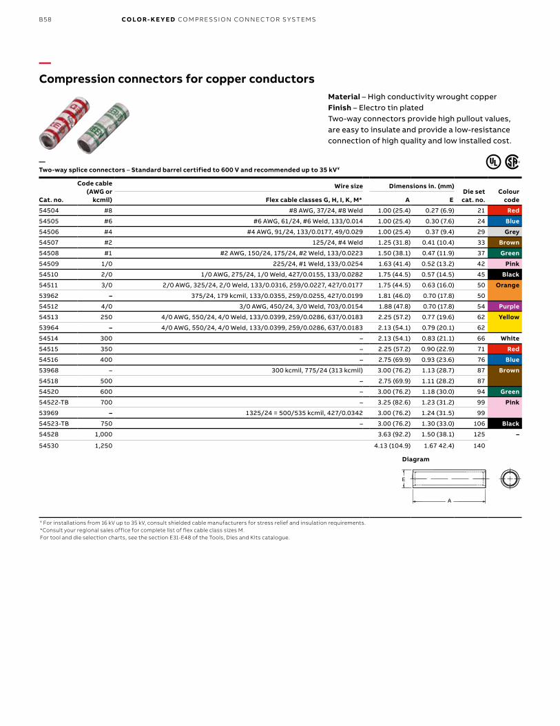
B58 CO LO R- K E Y E D CO M PR E SSI O N CO N N EC TO R S Y S TEMS
Cat. no.
Code cable (AWG or
kcmil)
Wire size Dimensions in. (mm)Die set cat. no.
Colour codeFlex cable classes G, H, I, K, M* A E
54504 #8 #8 AWG, 37/24, #8 Weld 1.00 (25.4) 0.27 (6.9) 21 Red
54505 #6 #6 AWG, 61/24, #6 Weld, 133/0.014 1.00 (25.4) 0.30 (7.6) 24 Blue
54506 #4 #4 AWG, 91/24, 133/0.0177, 49/0.029 1.00 (25.4) 0.37 (9.4) 29 Grey
54507 #2 125/24, #4 Weld 1.25 (31.8) 0.41 (10.4) 33 Brown
54508 #1 #2 AWG, 150/24, 175/24, #2 Weld, 133/0.0223 1.50 (38.1) 0.47 (11.9) 37 Green
54509 1/0 225/24, #1 Weld, 133/0.0254 1.63 (41.4) 0.52 (13.2) 42 Pink
54510 2/0 1/0 AWG, 275/24, 1/0 Weld, 427/0.0155, 133/0.0282 1.75 (44.5) 0.57 (14.5) 45 Black
54511 3/0 2/0 AWG, 325/24, 2/0 Weld, 133/0.0316, 259/0.0227, 427/0.0177 1.75 (44.5) 0.63 (16.0) 50 Orange
53962 – 375/24, 179 kcmil, 133/0.0355, 259/0.0255, 427/0.0199 1.81 (46.0) 0.70 (17.8) 50
54512 4/0 3/0 AWG, 450/24, 3/0 Weld, 703/0.0154 1.88 (47.8) 0.70 (17.8) 54 Purple
54513 250 4/0 AWG, 550/24, 4/0 Weld, 133/0.0399, 259/0.0286, 637/0.0183 2.25 (57.2) 0.77 (19.6) 62 Yellow
53964 – 4/0 AWG, 550/24, 4/0 Weld, 133/0.0399, 259/0.0286, 637/0.0183 2.13 (54.1) 0.79 (20.1) 62
54514 300 – 2.13 (54.1) 0.83 (21.1) 66 White
54515 350 – 2.25 (57.2) 0.90 (22.9) 71 Red
54516 400 – 2.75 (69.9) 0.93 (23.6) 76 Blue
53968 – 300 kcmil, 775/24 (313 kcmil) 3.00 (76.2) 1.13 (28.7) 87 Brown
54518 500 – 2.75 (69.9) 1.11 (28.2) 87
54520 600 – 3.00 (76.2) 1.18 (30.0) 94 Green
54522-TB 700 – 3.25 (82.6) 1.23 (31.2) 99 Pink
53969 – 1325/24 = 500/535 kcmil, 427/0.0342 3.00 (76.2) 1.24 (31.5) 99
54523-TB 750 – 3.00 (76.2) 1.30 (33.0) 106 Black
54528 1,000 3.63 (92.2) 1.50 (38.1) 125 –
54530 1,250 4.13 (104.9) 1.67 42.4) 140
¥ For installations from 16 kV up to 35 kV, consult shielded cable manufacturers for stress relief and insulation requirements.*Consult your regional sales office for complete list of flex cable class sizes M.For tool and die selection charts, see the section E31-E48 of the Tools, Dies and Kits catalogue.
—Compression connectors for copper conductors
Material – High conductivity wrought copperFinish – Electro tin platedTwo-way connectors provide high pullout values, are easy to insulate and provide a low-resistance connection of high quality and low installed cost.
— Two-way splice connectors – Standard barrel certified to 600 V and recommended up to 35 kV¥
A
E
A
E
Diagram
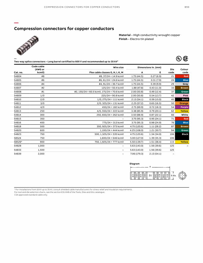
B59
Cat. no.
Code cable (AWG or
kcmil)
Wire size Dimensions in. (mm)Die
codeColour
codeFlex cable classes G, H, I, K, M A E
54804 #8 #8, 37/24 = 14.9 kcmil 1.75 (44.5) 0.27 (6.9) 21 Red
54805 #6 #6, 61/24 = 24.6 kcmil 1.75 (44.5) 0.31 (7.9) 24 Blue
54806 #4 #4, 91/24 = 36.7 kcmil 1.75 (44.5) 0.39 (9.9) 29 Grey
54807 #2 125/24 = 50.4 kcmil 1.88 (47.8) 0.43 (11.0) 33 Brown
54808 #1 #2, 150/24 = 60.5 kcmil, 175/24 = 70.6 kcmil 2.00 (50.8) 0.49 (12.4) 37 Green
54809 1/0 225/24 = 90.8 kcmil 2.00 (50.8) 0.54 (13.7) 42 Pink
54810 2/0 1/0, 275/24 = 111 kcmil 2.13 (54.1) 0.59 (15.0) 45 Black
54811 3/0 2/0, 325/24 = 131 kcmil 2.25 (57.2) 0.65 (16.5) 50 Orange
54812 4/0 450/24 = 182 kcmil 2.75 (69.9) 0.72 (18.3) 54 Purple
54813 250 4/0, 550/24 = 222 kcmil 3.38 (85.9) 0.79 (20.1) 62 Yellow
54814 300 250, 650/24 = 262 kcmil 3.50 (88.9) 0.87 (22.1) 66 White
54815 350 – 3.75 (95.3) 0.95 (24.1) 71 Red
54816 400 775/24 = 313 kcmil 3.75 (95.3) 0.98 (24.9) 76 Blue
54818 500 350, 925/24 = 373 kcmil 4.75 (120.6) 1.11 (28.2) 87 Brown
54820 600 1,100/24 = 444 kcmil 4.25 (108.0) 1.21 (30.7) 94 Green
54823 750 500, 1,325/24 = 535 kcmil 4.75 (120.6) 1.34 (34.0) 106 Black
58524 750 1,600/24 = 646 kcmil 5.00 (127.0) 1.39 (35.3) 106
58526* 900 750, 1,925/24 = 777 kcmil 5.50 (139.7) 1.51 (38.4) 115 Yellow
54828 1,000 – 5.63 (143.0) 1.56 (39.6) 125 –
54833 1,500 – 5.63 (143.0) 1.56 (39.6) 125
54839 2,000 – 7.06 (179.3) 2.13 (54.1) –
¥ For installations from 16 kV up to 35 kV, consult shielded cable manufacturers for stress relief and insulation requirements.For tool and die selection charts, see the section E31-E48 of the Tools, Dies and Kits catalogue.CSA approved standard cable only.
—Compression connectors for copper conductors
Material – High conductivity wrought copperFinish – Electro tin plated
— Two-way splice connectors – Long barrel certified to 600 V and recommended up to 35 kV¥
E DIA.
54 DIE
PURPLE
54 DIE
PURPLE 54 D
IE
PURP
LE
54 D
IE
PURP
LE
T&B
4/0
A
E dia.
Diagram
CO M PR E SSI O N CO N N EC TO R S FO R CO PPER CO N D U C TO R S
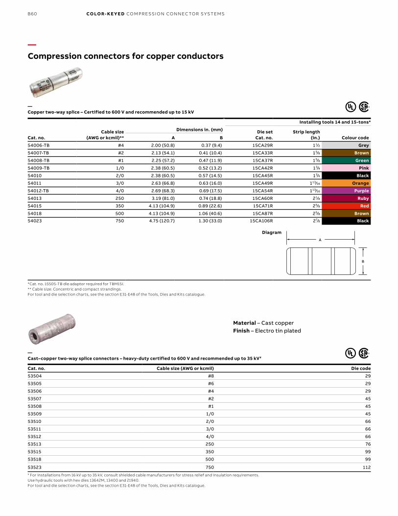
B60 CO LO R- K E Y E D CO M PR E SSI O N CO N N EC TO R S Y S TEMS
Cable size (AWG or kcmil)**
Installing tools 14 and 15-tons*
Dimensions in. (mm) Die setCat. no.
Strip length (in.) Colour codeCat. no. A B
54006-TB #4 2.00 (50.8) 0.37 (9.4) 15CA29R 11⁄2 Grey
54007-TB #2 2.13 (54.1) 0.41 (10.4) 15CA33R 15⁄8 Brown
54008-TB #1 2.25 (57.2) 0.47 (11.9) 15CA37R 15⁄8 Green
54009-TB 1/0 2.38 (60.5) 0.52 (13.2) 15CA42R 13⁄4 Pink
54010 2/0 2.38 (60.5) 0.57 (14.5) 15CA45R 13⁄4 Black
54011 3/0 2.63 (66.8) 0.63 (16.0) 15CA49R 113⁄16 Orange
54012-TB 4/0 2.69 (68.3) 0.69 (17.5) 15CA54R 113⁄16 Purple
54013 250 3.19 (81.0) 0.74 (18.8) 15CA60R 21⁄8 Ruby
54015 350 4.13 (104.9) 0.89 (22.6) 15CA71R 25⁄8 Red
54018 500 4.13 (104.9) 1.06 (40.6) 15CA87R 25⁄8 Brown
54023 750 4.75 (120.7) 1.30 (33.0) 15CA106R 27⁄8 Black
*Cat. no. 15505-TB die adaptor required for TBM15I.** Cable size: Concentric and compact strandings.For tool and die selection charts, see the section E31-E48 of the Tools, Dies and Kits catalogue.
A
B
A
B
Diagram
— Cast–copper two-way splice connectors – heavy-duty certified to 600 V and recommended up to 35 kV¥
Cat. no. Cable size (AWG or kcmil) Die code
53504 #8 29
53505 #6 29
53506 #4 29
53507 #2 45
53508 #1 45
53509 1/0 45
53510 2/0 66
53511 3/0 66
53512 4/0 66
53513 250 76
53515 350 99
53518 500 99
53523 750 112¥ For installations from 16 kV up to 35 kV, consult shielded cable manufacturers for stress relief and insulation requirements.Use hydraulic tools with hex dies 13642M, 13400 and 21940.For tool and die selection charts, see the section E31-E48 of the Tools, Dies and Kits catalogue.
—Compression connectors for copper conductors
Material – Cast copperFinish – Electro tin plated
— Copper two-way splice – Certified to 600 V and recommended up to 15 kV
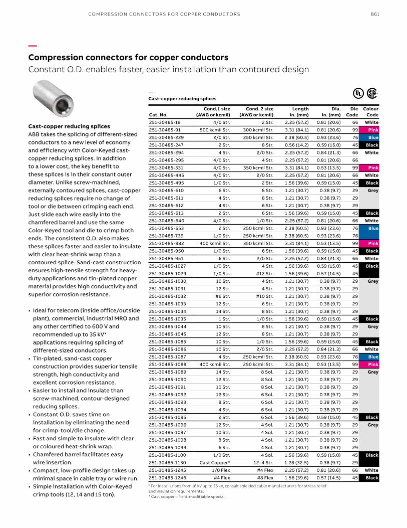
B61
—Compression connectors for copper conductorsConstant O.D. enables faster, easier installation than contoured design
— Cast-copper reducing splices
Cast-copper reducing splices ABB takes the splicing of different-sized conductors to a new level of economy and efficiency with Color-Keyed cast-copper reducing splices. In addition to a lower cost, the key benefit to these splices is in their constant outer diameter. Unlike screw-machined, externally contoured splices, cast-copper reducing splices require no change of tool or die between crimping each end. Just slide each wire easily into the chamfered barrel and use the same Color-Keyed tool and die to crimp both ends. The consistent O.D. also makes these splices faster and easier to insulate with clear heat-shrink wrap than a contoured splice. Sand-cast construction ensures high-tensile strength for heavy-duty applications and tin-plated copper material provides high conductivity and superior corrosion resistance.
• Ideal for telecom (inside office/outside plant), commercial, industrial MRO and any other certified to 600 V and recommended up to 35 kV¥ applications requiring splicing of different-sized conductors.
• Tin-plated, sand-cast copper construction provides superior tensile strength, high conductivity and excellent corrosion resistance.
• Easier to install and insulate than screw-machined, contour-designed reducing splices.
• Constant O.D. saves time on installation by eliminating the need for crimp-tool/die change.
• Fast and simple to insulate with clear or coloured heat-shrink wrap.
• Chamfered barrel facilitates easy wire insertion.
• Compact, low-profile design takes up minimal space in cable tray or wire run.
• Simple installation with Color-Keyed crimp tools (12, 14 and 15 ton).
Cat. No.Cond.1 size
(AWG or kcmil)Cond. 2 size
(AWG or kcmil)Length
in. (mm) Dia.
in. (mm) Die
CodeColour
Code
251-30485-19 4/0 Str. 2 Str. 2.25 (57.2) 0.81 (20.6) 66 White
251-30485-91 500 kcmil Str. 300 kcmil Str. 3.31 (84.1) 0.81 (20.6) 99 Pink
251-30485-229 2/0 Str. 250 kcmil Str. 2.38 (60.5) 0.93 (23.6) 76 Blue
251-30485-247 2 Str. 8 Str. 0.56 (14.2) 0.59 (15.0) 45 Black
251-30485-294 4 Str. 2/0 Str. 2.25 (57.2) 0.84 (21.3) 66 White
251-30485-295 4/0 Str. 4 Str. 2.25 (57.2) 0.81 (20.6) 66
251-30485-331 4/0 Str. 350 kcmil Str. 3.31 (84.1) 0.53 (13.5) 99 Pink
251-30485-445 4/0 Str. 2/0 Str. 2.25 (57.2) 0.81 (20.6) 66 White
251-30485-495 1/0 Str. 2 Str. 1.56 (39.6) 0.59 (15.0) 45 Black
251-30485-610 6 Str. 8 Str. 1.21 (30.7) 0.38 (9.7) 29 Grey
251-30485-611 4 Str. 8 Str. 1.21 (30.7) 0.38 (9.7) 29
251-30485-612 4 Str. 6 Str. 1.21 (30.7) 0.38 (9.7) 29
251-30485-613 2 Str. 6 Str. 1.56 (39.6) 0.59 (15.0) 45 Black
251-30485-640 4/0 Str. 1/0 Str. 2.25 (57.2) 0.81 (20.6) 66 White
251-30485-653 2 Str. 250 kcmil Str. 2.38 (60.5) 0.93 (23.6) 76 Blue
251-30485-739 1/0 Str. 250 kcmil Str. 2.38 (60.5) 0.93 (23.6) 76
251-30485-882 400 kcmil Str. 350 kcmil Str. 3.31 (84.1) 0.53 (13.5) 99 Pink
251-30485-950 1/0 Str. 6 Str. 1.56 (39.6) 0.59 (15.0) 45 Black
251-30485-951 6 Str. 2/0 Str. 2.25 (57.2) 0.84 (21.3) 66 White
251-30485-1027 1/0 Str. 4 Str. 1.56 (39.6) 0.59 (15.0) 45 Black
251-30485-1029 1/0 Str. #12 Str. 1.56 (39.6) 0.57 (14.5) 45
251-30485-1030 10 Str. 4 Str. 1.21 (30.7) 0.38 (9.7) 29 Grey
251-30485-1031 12 Str. 4 Str. 1.21 (30.7) 0.38 (9.7) 29
251-30485-1032 #6 Str. #10 Str. 1.21 (30.7) 0.38 (9.7) 29
251-30485-1033 12 Str. 6 Str. 1.21 (30.7) 0.38 (9.7) 29
251-30485-1034 14 Str. 8 Str. 1.21 (30.7) 0.38 (9.7) 29
251-30485-1035 1 Str. 1/0 Str. 1.56 (39.6) 0.59 (15.0) 45 Black
251-30485-1044 10 Str. 8 Str. 1.21 (30.7) 0.38 (9.7) 29 Grey
251-30485-1045 12 Str. 8 Str. 1.21 (30.7) 0.38 (9.7) 29
251-30485-1085 10 Str. 1/0 Str. 1.56 (39.6) 0.59 (15.0) 45 Black
251-30485-1086 10 Str. 2/0 Str. 2.25 (57.2) 0.84 (21.3) 66 White
251-30485-1087 4 Str. 250 kcmil Str. 2.38 (60.5) 0.93 (23.6) 76 Blue
251-30485-1088 400 kcmil Str. 250 kcmil Str. 3.31 (84.1) 0.53 (13.5) 99 Pink
251-30485-1089 14 Str. 8 Sol. 1.21 (30.7) 0.38 (9.7) 29 Grey
251-30485-1090 12 Str. 8 Sol. 1.21 (30.7) 0.38 (9.7) 29
251-30485-1091 10 Str. 8 Sol. 1.21 (30.7) 0.38 (9.7) 29
251-30485-1092 12 Str. 6 Sol. 1.21 (30.7) 0.38 (9.7) 29
251-30485-1093 8 Str. 6 Sol. 1.21 (30.7) 0.38 (9.7) 29
251-30485-1094 4 Str. 6 Sol. 1.21 (30.7) 0.38 (9.7) 29
251-30485-1095 2 Str. 6 Sol. 1.56 (39.6) 0.59 (15.0) 45 Black
251-30485-1096 12 Str. 4 Sol. 1.21 (30.7) 0.38 (9.7) 29 Grey
251-30485-1097 10 Str. 4 Sol. 1.21 (30.7) 0.38 (9.7) 29
251-30485-1098 8 Str. 4 Sol. 1.21 (30.7) 0.38 (9.7) 29
251-30485-1099 6 Str. 4 Sol. 1.21 (30.7) 0.38 (9.7) 29
251-30485-1100 1/0 Str. 4 Sol. 1.56 (39.6) 0.59 (15.0) 45 Black
251-30485-1130 Cast Copper* 12–4 Str. 1.28 (32.5) 0.38 (9.7) 29
251-30485-1245 1/0 Flex #4 Flex 2.25 (57.2) 0.81 (20.6) 66 White
251-30485-1246 #4 Flex #8 Flex 1.56 (39.6) 0.57 (14.5) 45 Black¥ For installations from 16 kV up to 35 kV, consult shielded cable manufacturers for stress relief and insulation requirements.* Cast copper – field-modifiable special.
CO M PR E SSI O N CO N N EC TO R S FO R CO PPER CO N D U C TO R S


![Index [] · 2010. 4. 30. · Copper Alloy Mechanical Connectors CD_BB Line Mechanical terminals One U-bolt type terminals for copper conductors. Copper alloy terminals with round](https://img.dokumen.tips/doc/110x75/5fe21e440f47565e460947a6/index-2010-4-30-copper-alloy-mechanical-connectors-cdbb-line-mechanical.jpg)