Embed Size (px)
Citation preview

Compressed Air Foam SystemUser Operation Manual
Manual p/n: 029-0020-75-0
Hale Products Inc. ◆ A Unit of IDEX Corporation700 Spring Mill Avenue ◆ Conshohocken, PA 19428 U.S.A.
Telephone: 610-825-6300 ◆ FAX: 610-825-6440Web: www.haleproducts.com

NOTICE !
Class1 cannot assume responsibility for product failure resulting from improper maintenance or operation. Class1 is responsible only to the limits stated in the product warranty. Product specifications contained in this manual are subject to change without notice.
All Class1 products are quality components -- ruggedly designed, accurately machined, precision inspected, carefully assembled and thoroughly tested. In order to maintain the high quality of your unit, and to keep it in a ready condition, it is important to follow the instructions on care and operation. Proper use and good preventive maintenance will lengthen the life of your unit.
ALWAYS INCLUDE THE UNIT SERIAL NUMBERIN YOUR CORRESPONDENCE.
ECO NO REV CHANGE FROM BY DATE APVD
HALE PRODUCTS, INC.A Unit of IDEX Corporation
Conshohocken, PA 19428 USA
0032 A INITIAL RELEASE LwH 02/14/2005
DRAWN BY LwH ISSUE DATE COPYRIGHT ©NOT TO BE REPRODUCED OR USED TO
MAKE OTHER DRAWINGS OR MACHINERY.CHECKED BY 02/14/2005
Manual p/n: 029-0020-75-0, Rev. -APrinted in U.S.A.
© Hale Products, Inc. 2005All Rights Reserved
APPARATUS INFORMATION
ENGINE ______________________________________________
TRANSMISSION _______________________________________
MAXIMUM CAFS ENGINE RPM ___________________________
CAFS ENGINE SPEED RANGE ___________________________

Contents Page
Table of Contents ❑
3CAFSPro User Operation Manual p/n: 029-0020-75-0
CAFSPro User Operations Manual
1 Safety Precautions...................................................................................7
1.1 Safety Guidelines ................................................................................................... 7
2 How the CAFSPro System Works.......................................................13
Figure 2-1: Normal Compressed Air Foam System ............................................... 13Figure 2-2: Hale CAFSPro Compressed Air Foam System ................................... 14Figure 2-3: Boyle’s Law - Schematic Representation ............................................ 16
Hale FoamLogix System .................................................................................................... 17
Figure 2-4: CAFSPro Pump System Overview ...................................................... 19
3 Controls and Indicators .......................................................................21
Figure 3-1: Operator Panel Arrangement.............................................................. 21
3.1 Engine Controls and Indicators.......................................................................... 22Pump Controls.................................................................................................................... 22
Pressure Gauges ............................................................................................................... 22
Master Duplex Pressure Gauge................................................................................... 22
Master Pump Suction Gauge ....................................................................................... 23
Line Discharge Pressure Gauge .................................................................................. 23
Hale FoamLogix Controls and Indicators .......................................................................... 23
Control Unit .................................................................................................................. 23
Figure 3-2: Hale FoamLogix Control Unit............................................................... 23
Optional Dual Tank System ......................................................................................... 24
Figure 3-3: Dual Tank Selectors............................................................................. 24
Manual Single Tank (MST) Flush Selector .................................................................. 24
Figure 3-4: Manual Single-Tank Flush Selector ..................................................... 24
FS Series Foam Strainers............................................................................................ 25
Figure 3-5: FS Series Strainers.............................................................................. 25
Hale Instruction Placard ............................................................................................... 26
Figure 3-6: Hale Single and Dual Tank Instruction Placards.................................. 26
Hale CAFSPro Display................................................................................................. 26
Figure 3-7: Hale CAFSPro Control Unit ................................................................. 26

Contents - continued Page
❑ Table of Contents
4 CAFSPro User Operation Manualp/n: 029-0020-75-0
3.1 Engine Controls and Indicators - continuedAudible Alarm .............................................................................................................. 27
Figure 3-8: Audible Alarm ...................................................................................... 27
4 Basic Operation....................................................................................29
Figure 4-1: Typical CAFSPro System Operator Panel Control Arrangement ........ 29
4.1 Turn off CAFSPro and FoamLogix......................................................................30
4.2 System Parts and Components ..........................................................................30
4.3 Hale CAFSPro Operation .....................................................................................31Flowing Compressed Air Foam.......................................................................................... 31
FoamLogix Push Button Display........................................................................................ 32
Figure 4-2: Hale FoamLogix Control Unit .............................................................. 32
CAFSPro Push Button Display .......................................................................................... 33
Figure 4-3: Hale CAFSPro Control Unit ................................................................. 33Figure 4-4: Sample, Display ICONS ...................................................................... 34
4.4 Water, Foam Solution, and CAFS .......................................................................34
4.5 Creating finished foams.......................................................................................35Operation ........................................................................................................................... 35
Compressor ....................................................................................................................... 37
Tanks ................................................................................................................................. 37
4.6 CAFSPro Safety Protocols ..................................................................................38
4a Operating procedures...........................................................................39
4a.1 Water Supply.........................................................................................................40Figure 4-5: CAFSPro Typical Operating Ranges................................................... 41
Engage Pump .................................................................................................................... 42
Establish Discharge Pressure............................................................................................ 42
Figure 4-6: Master Gauge CAFSPro Pressure Range........................................... 42
Set Relief Valve ................................................................................................................. 43
Figure 4-7: Relief Valve Control............................................................................. 43
Open Discharge Valve(s)................................................................................................... 44
Open CAFS Discharge ...................................................................................................... 44
Check FoamLogix and Air Flow Readings......................................................................... 44

Contents - continued Page
Table of Contents ❑
5CAFSPro User Operation Manualp/n: 029-0020-75-0
4a.1 Water Supply - continuedDuplex Master Pressure Gauge................................................................................... 44
Hale FoamLogix Control Unit ....................................................................................... 44
Hale CAFSPro Display Unit ......................................................................................... 45
Wet and Dry Foam ............................................................................................................. 45
4b CAFS Operation Summary..................................................................45
4b.1 Procedure ............................................................................................................. 45
4b.2 CAFS SYSTEM MESSAGES ................................................................................ 46
5 System Shutdown ..................................................................................47
5.1 For system shutdown .......................................................................................... 47
6 Troubleshooting ....................................................................................49
6.1 Water Pump .......................................................................................................... 49
6.2 Hale FoamLogix System...................................................................................... 49
6.3 Air Compressor .................................................................................................... 49
6.4 Hale CAFSPro....................................................................................................... 49CAFSPro Error Codes ....................................................................................................... 50
High Air Pressure ............................................................................................................... 50
Low Air Flow/Poor Quality Dry Foam ................................................................................. 50
7 Routine Maintenance............................................................................51
7.1 Air Compressor Moisture Drain.......................................................................... 51Drain Moisture .................................................................................................................... 51
Figure 7-1: Maintenance Overview ........................................................................ 52
7.2 Oil and Oil Filter ................................................................................................... 53To Change Oil and Oil Filter............................................................................................... 53
7.3 Compressor Clutch Grease................................................................................. 55
7.4 Cooling Water Strainer ........................................................................................ 55

Contents - continued Page
❑ Table of Contents
6 CAFSPro User Operation Manualp/n: 029-0020-75-0
7.5 Air Cleaner Element .............................................................................................56
7.6 Compressor Belt Tension Adjustment ...............................................................56General .............................................................................................................................. 56
Figure 7-2: Removing the Belt Guard .................................................................... 56
Remove Belt Guard ........................................................................................................... 56
To Check Tension.............................................................................................................. 57
Figure 7-3: Belt Tension Gauge............................................................................. 57Figure 7-4: Tension Gauge .................................................................................... 57
To Measure and Adjust Belt Tension................................................................................. 58
Figure 7-5: Measuring Tension using a Scale ....................................................... 58Figure 7-6: Belt Tension Adjustment Bolts............................................................. 59
7.7 Hot Shift Clutch Option........................................................................................59Figure 7-7: Hot Shift Oil Sight Tube ....................................................................... 60
8 Calibration.............................................................................................61
8.1 Entering Passwords .............................................................................................61Table 8-1: Default Passwords................................................................................ 61Figure 8-2: Sample PASS Display ......................................................................... 61
8.2 Calibration.............................................................................................................62To Begin............................................................................................................................. 62
Water Flow Calibration....................................................................................................... 62
Figure 8-3: Sample CAFSPro Display Readouts -1............................................... 63Figure 8-4: Sample CAFSPro Display Readouts -2............................................... 64
8.3 Water Flow Sensor Calibration ...........................................................................64Record Water Flow Sensor Calibration Factors................................................................. 65
8.4 Exiting and Saving Calibration ...........................................................................66
Appendix A: Foam Concentrate Compatibility .................................67
Chart A-1: Hale Class “A” Foam Concentrate Compatibility .................................. 67Chart A-2: Hale Class “B” Foam Concentrate Compatibility .................................. 68
Reference .......................................................................................................................... 69
Express Warranty ....................................................................71

Safety Precautions ❑
7CAFSPro User Operation Manualp/n: 029-0020-75-0
1 Safety Precautions
IMPORTANT !
THE HALE CAFSPRO® PUMP SYSTEM (OR CAFSPRO) IS DESIGNED FOR OPTIMUM SAFETY OF ITS OPERATORS. FOR ADDED PROTECTION, PLEASE FOLLOW THE SAFETY GUIDELINES LISTED IN THIS SECTION AND ADHERE TO ALL WARNING, DANGER, CAUTION AND IMPORTANT NOTES FOUND WITHIN THIS MANUAL.
THIS SECTION ON SAFETY MUST BE CAREFULLY READ, UNDERSTOOD AND ADHERED TO STRICTLY BY ALL INSTALLERS AND OPERATORS BEFORE ATTEMPTING TO INSTALL OR OPERATE THE CAFSPRO PUMP SYSTEM.
CAFSPro is a registered trademark of Hale Products, Incorporated. All other brand and product names are the trademarks of their respective holders.
1.1 SAFETY GUIDELINES
READ ALL INSTRUCTIONS THOROUGHLY BEFORE BEGINNING
ANY INSTALLATION PROCESS.
❑ This manual covers basic operation of the Hale CAFSPro Pump Sys-tem installed on the apparatus and related subsystems.
For detailed operation and maintenance instructions refer to the com-ponent manuals supplied with the individual components.
❑ A compressed air foam system can be a valuable fire fighting tool; however, proper operation and proper tactical use of this tool needs to be addressed through training and education.
Further education and training on foam and compressed air foam is required for effective and safe fire fighting use of this equipment.
Dry foam is not recommended for structural fire suppression or direct fire attack.
❑ Make sure proper personal protective equipment is used when operat-ing or servicing apparatus.
❑ Rotating drive line parts can cause injury. Be extremely careful that NO part of your body (head, feet, arms, legs, finger, hair) is in an area of rotating parts where you could be subject to injury.

❑ Safety Precautions
8 CAFSPro User Operation Manualp/n: 029-0020-75-0
❑ Before attempting to start the CAFSPro make sure to close all manual drains and discharge valves.
❑ Adding compressed air to the hose line dramatically increases the energy content.
Hose lines charged with compressed air foam have very little weight but contain large amounts of energy.
❑ CAFS Systems add power to the fire stream via compressed air. Proper education, training and nozzle selection are required for opera-tional effectiveness and safety. Greater nozzle reaction can be expected from some nozzles.
❑ Nozzle selection – Hale does not recommend any specific type or brand of nozzle for use with the CAFSPro system.
Each fire department must conduct its own evaluation to ensure an appropriate nozzle choice for the various types of hazards they expect to encounter. Each fire department must develop associated opera-tional procedures and guidelines. Hale Products, Inc. does not rec-ommend or claim suitability or fitness for any given nozzle brand or style.
WARNING !
ONCE A NOZZLE HAS BEEN SELECTED IT IS IMPERATIVE TO PROVIDE AMPLE TRAINING IN THE USE OF THE NOZZLE. OPEN CAFS NOZZLES SLOWLY AND MAKE SURE THE NOZZLE IS SECURED AGAINST REACTION FORCE.
❑ Do not remove the cap from the FS series foam strainer while the Hale FoamLogix unit is running and the fire pump is engaged or connected to a pressurized water supply.
❑ Projectiles can cause injury. DO NOT use a blank hose cap on CAFS discharges. CAFS stores energy, in the form of compressed air, in piping that could turn a blank hose cap into a projectile when removed.
❑ Wet surfaces become slippery. Use care when climbing on the appa-ratus during operations.
❑ Attack hoses for use with CAFS systems must be suitable for use with CAFS. Refer to Hale Bulletin 686 for a listing of attack hoses approved by hose manufacturers for use with Hale CAFSPro systems.
❑ With the foam selector in the flush position or with water in the foam tanks, the operator is proportioning water into the discharge stream and slug flow can result. Always select foam tank prior to starting operations when the apparatus is equipped with a dual foam tank system.

Safety Precautions ❑
9CAFSPro User Operation Manualp/n: 029-0020-75-0
❑ DO NOT perform maintenance on the Hale CAFSPro system while the unit is running. Make sure the system is shut down and components have cooled before attempting maintenance.
❑ The operating pressure range of the CAFSPro compressed air foam system is 75-150 psi (5.2-10.4 BAR).
WARNING !
DO NOT EXCEED 150 PSI (10.3 BAR).
❑ Do not use a pump pressure governor in the pressure control mode with a CAFS system. Reduced pump speed, inherent in a pressure governor in the PSI mode, reduces the effectiveness of the CAFS fire fighting output streams. Use only the RPM or Speed Control modes.
CAUTION !
THE PROPER OIL LEVEL MUST BE MAINTAINED IN THE AIR COMPRESSOR SYSTEM AT ALL TIMES. LOW OIL LEVEL OR NO OIL COULD RESULT IN EXCESSIVE COMPRESSOR TEMPERATURE AND POSSIBLE COMPRESSOR FIRE. OVER FILLING AIR COMPRESSOR SYSTEM WILL RESULT IN SYSTEM MALFUNCTIONING.
THE FIRE PUMP IS EQUIPPED WITH A MECHANICAL SEAL. DO NOT RUN PUMP DRY FOR EXTENDED PERIODS OF TIME OR SEAL DAMAGE COULD RESULT.
DO NOT EXCEED 195°F (91°C) DURING AIR COMPRESSOR SYSTEM OPERATION.
❑ DO NOT remove or alter any guard or insulating devices, or attempt to operate the system when these guards are removed.
Make sure all access/service panels and covers are installed, closed and latched tight, where applicable.
❑ DO NOT remove or alter any hydraulic or pneumatic connections, electrical devices, etc. DO NOT tamper with or disconnect safety fea-tures or modify protective guards (such as covers or doors). DO NOT add or remove structural parts.
Doing so voids the CAFSPro warranty.
Any of the above could affect system capacity and/or safe operation of the system and is a serious safety violation which could cause per-sonal injury, weaken the construction of the system or affect safe oper-ation of the CAFSPro Pump System.
❑ Safety Precautions
10 CAFSPro User Operation Manualp/n: 029-0020-75-0
WARNING !
NO MODIFICATIONS OR ADDITIONS MAY BE MADE TO THE CAFSPRO PUMP SYSTEM WITHOUT PRIOR WRITTEN PERMISSION FROM:
Hale Products, IncorporatedFire Suppression Division
700 Spring Mill Avenue
Conshohocken, PA 19428 U.S.A.
Telephone:......610-825-6300
Fax:.................610-825-6440
Web .............www.haleproducts.com
❑ To prevent electrical shock always disconnect the primary power source before attempting to service any part of the Hale CAFSPro pump system.
❑ All electrical systems have the potential to cause sparks during service. Take the necessary precautions to eliminate explosive or hazardous environments during any installation/service.
❑ To prevent system damage or electrical shock, the main power supply wire must be the last connection made to the CAFSPro system electrical distribution box.
❑ Hale CAFSPro system is designed for use on negative (-) ground, direct current, electrical systems only.
❑ Always disconnect the power cable, ground straps, electrical wires and control cables from the control unit or other CAFSPro system equipment before electric arc welding at any point on the apparatus. Failure to do so could result in a power surge through the unit that could cause irrepa-rable damage.
❑ Before connecting the cord sets and wiring harnesses, inspect the seal washer in the female connectors. If the seal washer is missing or dam-aged, water can enter the connector causing pins and terminal corrosion. This results in possible system failure.
❑ Relieve all system pressure, then drain all foam concentrate and water from the system before servicing any of its component parts.
❑ Foam tank “low level” sensors must be utilized to protect the foam pro-portioner from dry running. Failure to use “low level” sensors voids the warranty.
❑ Use only pipe, hose and fittings, from the foam pump outlet to the injector fitting, which are rated at or above the maximum pressure rating at which the water pump system operates.
Safety Precautions ❑
11CAFSPro User Operation Manualp/n: 029-0020-75-0
❑ DO NOT mount a radio transmitter or transmitter cables in direct or close contact with the CAFSPro control unit. Direct contact could cause elec-trical interference and disrupt the control panel or radio operations.
❑ DO NOT connect the foam pump main power lead to small leads that are supplying some other device, such as a light bar or siren. The Hale FoamLogix Model 3.3 and Model 5.0 require 60 AMP minimum current and a 200 AMP (peak) minimum disconnect.
❑ When operating the Hale FoamLogix in Simulated Flow Mode an outlet for the foam concentrate must be provided to prevent excessive pressure buildup in the discharge piping or hoses.
❑ Make sure the foam tank and foam concentrate suction hoses are clean before making final connection to foam pump. If necessary, flush the tank and hoses prior to making any connections.

❑ Safety Precautions
12 CAFSPro User Operation Manualp/n: 029-0020-75-0
Notes
______________________________________________________________________________________________________________________________________________________________________________________________________________________________________________________________________________________________________________________________________________________________________________________________________________________________________________________________________________________________________________________________________________________________________________________________________________________________________________________________________________________________________________________________________________________________________________________________________________________________________________________________________________________________________________________________________________________________________________________________________________________________________________________________________________________________________________________________________________________________________________________________________________________________________________________________________________________________________________________________________________________________________________________________________________________________________________________________________________________________________________________________________________________________________________________________________________________________________________________________________________________________________________________________________________________________________________________________________________________________________________________________________________________________________________________________________________________________________________________________________________________________________________________________________________________________________________________________________________________________________________________________________________________________________________________________________________________________________________________________________________________________________________________________________

Overview ❑
13CAFSPro User Operation Manualp/n: 029-0020-75-0
2 How the CAFSPro System Works
A normal Compressed Air Foam System (CAFS) combines the fire-fighting proper-ties of water and foam concentrate along with the power of compressed air. (See Figure 2-1: ‘Normal Compressed Air Foam System.’)
Figure 2-1: Normal Compressed Air Foam System
The Hale CAFSPro® system controls the combination of three components, water, foam concentrate and compressed air – to make compressed air foam. (See Fig-ure 2-2: ‘Hale CAFSPro Compressed Air Foam System,’ on page 14.) The CAF-SPro system injects foam concentrate into the water discharge stream using the Hale FoamLogix Foam Proportioning System. Air is then supplied by the Air Com-pressor System. The CAFSPro system monitors the water flow rate and foam con-centrate injection. The CAFSPro system only allows air injection if water is flowing and foam concentrate is being injected by the FoamLogix into the water stream.

❑ Overview
14 CAFSPro User Operation Manualp/n: 029-0020-75-0
Figure 2-2: Hale CAFSPro Compressed Air Foam System
The Hale FoamLogix foam proportioning system uses a rugged Class 1 flow sensor to measure water flowing out the foam capable discharge(s). The Hale FoamLogix control unit has a computer chip that constantly compares the water flow and foam concentrate flow rates to inject the proper amount of foam concentrate based on the operator selected injection rate. The operator can select any foam concentrate injection rate at the control unit from 0.1% to 10.0% dependent on fire ground requirements. The control unit provides the operator with the water flow rate as well as total water flowed, foam concentrate injection rate and total foam concen-trate used.
Overview ❑
15CAFSPro User Operation Manualp/n: 029-0020-75-0
Foam solution is available once the foam concentrate is added to the fire pump dis-charge. Discharge valves, plumbed into the system, provide foam solution, not CAFS. To obtain CAFS, air must be added to create compressed air foam.
The Compressor System is designed to deliver continuous duty performance. Compressed air is added proportionally into the foam solution flow, controlled by the CAFSPro controller. The CAFSPro monitors the air flow and provides a digital readout on the control panel.
Mixers, downstream of the air injection point, assure proper foam mixing before dis-charge. Compressed air foam is available through the compressed air foam dis-charge valves on the apparatus.
The Air Compressor includes a closed-loop lubrication system that both lubricates and cools the compressor. A water-to-oil heat exchanger is added to cool the air compressor oil. An “optional” standby air to oil cooler is an additional option to reduce the amount of heat transferred into the pump water in warm climates.
Compressed Air Foam produced by the Hale CAFSPro system varies in consis-tency from WET to DRY by adjusting the CAFSPro control on the pump operator panel. DRY foam contains more air than water. This can be valuable in exposure protection, creating a thick long lasting foam blanket. WET foams generally have approximately 0.5 to 1.0 SCFM of air for every GPM of water and are usually used for direct attack.
WARNING !
A COMPRESSED AIR FOAM SYSTEM CAN BE A VALUABLE FIRE FIGHTING TOOL. HOWEVER, PROPER OPERATION AND TACTICAL USE OF THIS TOOL NEEDS TO BE ADDRESSED THROUGH TRAINING AND EDUCATION.
THIS MANUAL COVERS BASIC OPERATION OF THE HALE CAFSPRO SYS-TEM. FURTHER EDUCATION AND TRAINING ON FOAM AND COMPRESSED AIR FOAM IS REQUIRED FOR EFFECTIVE AND SAFE FIRE FIGHTING USE OF THIS EQUIPMENT.
DRY FOAM IS NOT RECOMMENDED FOR STRUCTURAL FIRE SUPPRESSION OR DIRECT FIRE ATTACK.
CAFS discharge hoses are handled differently than plain water hoses at the same pressure.
❑ Lighter Hoses
Because a CAFS hose line is filled with almost half air in the form of foam bubbles, a 1-3/4” (45 mm) hose line handles more like a 1” (25.4 mm) line. The hose line floats on water and is easier to advance.

❑ Overview
16 CAFSPro User Operation Manualp/n: 029-0020-75-0
❑ Nozzle Reaction/Compressibility of Air
Compressed air foam hose lines, by definition, contain a mixture of com-pressed air, foam and water. Since compressed air stores energy, a surge is felt when opening the nozzle as the air escapes.
Open the nozzle slowly to minimize this surge. Also see Section “1 Safety Precautions” on page 7 for additional nozzle reaction information.
To better understand nozzle reaction and the high energy nature of compressed air foam, the compressibility of air as defined by Boyle’s Law can be studied.
Boyle’s Law states: If the temperature is kept constant, the volume of a gas will vary inversely as the absolute pressure, while the density will vary directly as the pressure. Since the pres-sure and volume of a gas are inversely related — the higher the pressure, the smaller the vol-ume, and vice versa.
Figure 2-3: Boyle’s Law - Schematic Representation
The formula for Boyle’s law is: PV=C.
Where P = Absolute Pressure; V = Volume and C = Constant
Figure 2-3: “Boyle’s Law - Schematic Representation“ shows that the origi-nal volume of compressed air is reduced as the pressure increases by a directly proportionate factor.
As the schematic shows, with six more atmospheres [88.2 PSI (6 BAR)] of pressure added, the air pressure is now seven atmospheres [102.9 PSI (7 BAR)], and the original volume has been reduced by a factor of one-seventh (1/7). As more pressure is added, each atmosphere [14.7 PSI (1 BAR)] of pressure directly reduces the volume of air by the factor shown.

Overview ❑
17CAFSPro User Operation Manualp/n: 029-0020-75-0
In addition to the normal hydraulics at work in a fire ground operation, using CAFS also adds pneumatics. Therefore, “hydro-pneumatics” is the governing physics at work when using CAFS.
Pump operators and firefighters should keep the following items in mind:
WARNING !
ADDING COMPRESSED AIR TO THE HOSE LINE WILL DRAMATICALLY INCREASE THE ENERGY CONTENT. IF PERSONNEL ARE NOT PREPARED, A DANGEROUS SITUATION CAN RESULT. HOSE LINES CHARGED WITH COMPRESSED AIR FOAM HAVE VERY LITTLE WEIGHT BUT CONTAIN LARGE AMOUNTS OF ENERGY. “OPEN CAFS NOZZLES SLOWLY.”
The operating pressure on CAFS hose lines can be lowered to make them easier to handle. CAFS hand lines are typically “pumped” at 90 to 100 PSI (6-7 BAR) for a typical pre-connected 1-3/4” (45 mm) hose line.
Each fire department must conduct practical tests to find the appropriate pump pressure required to move the agent (GPM/SCFM) into, through and out the end of a hose line, monitor (if used) and the nozzle selected.
WARNING !
PLAIN WATER AND AIR DO NOT MIX.
WHEN AIR IS INJECTED INTO A WATER STREAM WITHOUT FOAM CONCEN-TRATE, A CONDITION CALLED “SLUG FLOW” WILL OCCUR. SLUG FLOW CAN CREATE VIOLENT HOSE PULSATIONS. “CHATTER” IS THE CONDI-TION WHERE INSUFFICIENT FOAM CONCENTRATE IS BEING INJECTED. THIS IS A LESS SEVERE FORM OF SLUG FLOW. SLUG FLOW AND CHAT-TER CAN DAMAGE HOSE LINES AND COULD CAUSE THE NOZZLE OPERA-TOR TO LOSE CONTROL OF THE NOZZLE. ALSO SEE HEADING “HALE FOAMLOGIX SYSTEM” ON PAGE 17.
Hale FoamLogix System
The Hale CAFSPro Foam Proportioning System uses an exclusive safety enhancement interlock to help prevent Slug Flow.
Air and water do not mix, so it is important that foam chemical be added to the water prior to air injection.

❑ Overview
18 CAFSPro User Operation Manualp/n: 029-0020-75-0
Air is not allowed to flow into the discharge unless water flow and pressure are available. The Hale FoamLogix system is activated and starts the foam concentrate injection when the air compressor is engaged. This important safety enhancement feature helps to prevent “slug flow” or air and water only from being discharged into the hose line. If the water pump is not primed, or the Hale FoamLogix foam system is OFF or out of foam, the Hale CAFSPro control does not allow air injection.
When water and foam concentrate are properly supplied, the Hale CAFS-Pro air flowmeter safety interlock allows air to flow into the CAFS capable discharge.
WARNING !
WITH WATER IN THE FOAM TANKS, THE OPERATOR IS PROPORTIONING WATER INTO THE DISCHARGE STREAM AND SLUG FLOW CAN RESULT. ALWAYS SELECT THE FOAM TANK PRIOR TO STARTING OPERATIONS, WHEN THE APPARATUS IS EQUIPPED WITH A DUAL FOAM TANK SYSTEM.
ENSURE THE FOAM TANK CONTAINS AN APPROVED FOAM CONCEN-TRATE. (SEE APPENDIX A “FOAM CONCENTRATE COMPATIBILITY,” BEGINNING ON PAGE 67.)
DO NOT USE WATER IN THE FOAM TANKS!

Overview ❑
19CAFSPro User Operation Manualp/n: 029-0020-75-0
Figure 2-4: CAFSPro Pump System Overview

❑ Overview
20 CAFSPro User Operation Manualp/n: 029-0020-75-0
Notes
______________________________________________________________________________________________________________________________________________________________________________________________________________________________________________________________________________________________________________________________________________________________________________________________________________________________________________________________________________________________________________________________________________________________________________________________________________________________________________________________________________________________________________________________________________________________________________________________________________________________________________________________________________________________________________________________________________________________________________________________________________________________________________________________________________________________________________________________________________________________________________________________________________________________________________________________________________________________________________________________________________________________________________________________________________________________________________________________________________________________________________________________________________________________________________________________________________________________________________________________________________________________________________________________________________________________________________________________________________________________________________________________________________________________________________________________________________________________________________________________________________________________________________________________________________________________________________________________________________________________________________________________________________________________________________________________________________________________________________________________________________________________________________________________________
Controls and Indicators ❑
21CAFSPro User Operation Manualp/n: 029-0020-75-0
3 Controls and Indicators
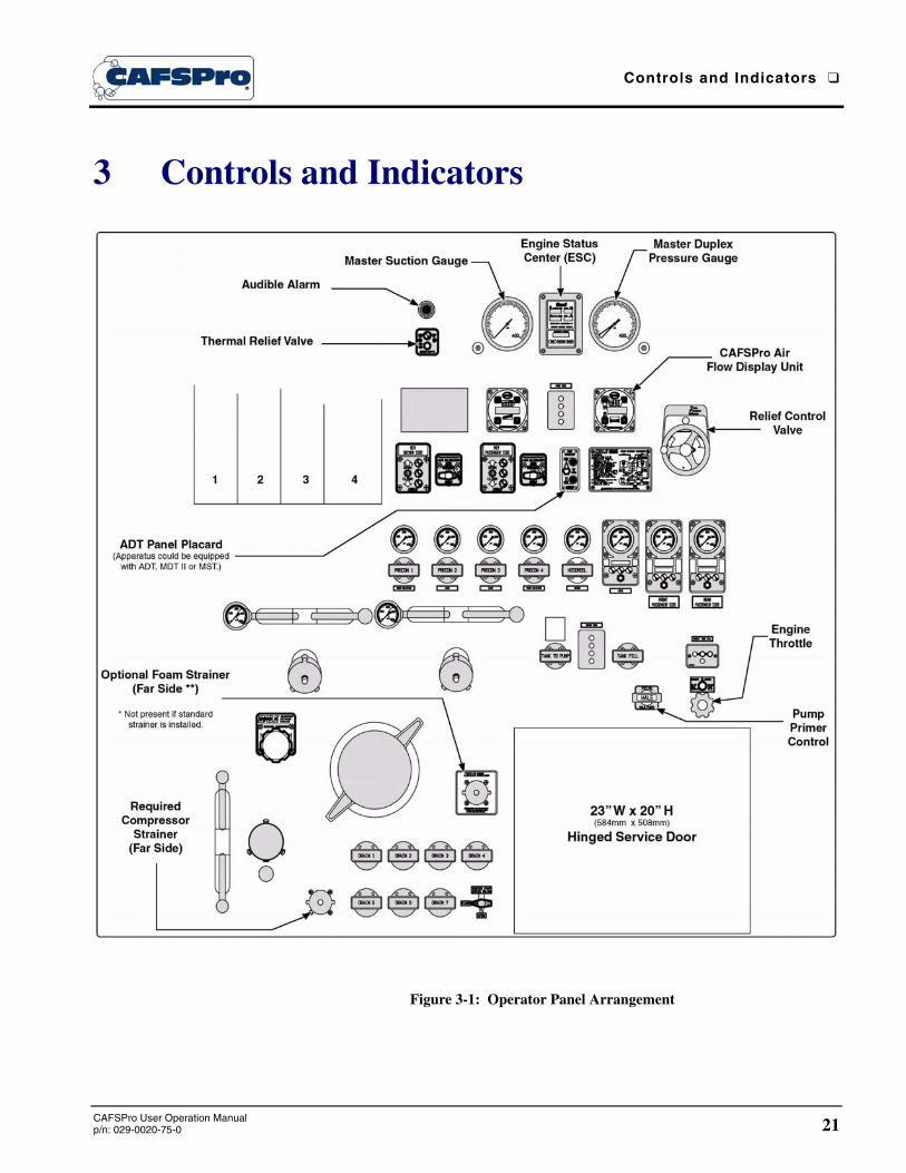
Figure 3-1: Operator Panel Arrangement

❑ Controls and Indicators
22CAFSPro User Operation Manual
p/n: 029-0020-75-0
The operator panel of the apparatus contains controls and indicators that are nec-essary for its operation and for operation of the CAFSPro Pump System. Before operating the apparatus and CAFSPro, the operator must become familiar with the location and function of these controls.
The following is a summary of the controls and indicators used during operation of the CAFSPro system, along with a description of their function. (See Figure 3-1: ‘Operator Panel Arrangement’ on page 21.) This panel arrangement is provided to aid in component identification only. Each operator must become familiar with the location of the controls and indicators on his/her individual apparatus.
3.1 ENGINE CONTROLS AND INDICATORS
(See Figure 3-1: ‘Operator Panel Arrangement’ on page 21.)
The operator panel contains controls and indicators to monitor and control operation of the apparatus engine during CAFSPro system operation. Con-sult the apparatus operation and maintenance manual provided by the apparatus builder for a description of these controls.
Pump Controls
Controls are located on the operator panel to operate the apparatus fire pump. Consult the apparatus operation and maintenance manual provided by the apparatus builder for a description of these controls.
Pressure Gauges
The following pressure gauges provide an indication of water inlet and dis-charge pressures along with the compressed air discharge pressure.
Master Duplex Pressure Gauge
This gauge indicates the discharge pressure of water and compressed air. The BLACK needle indicates the water pressure and the RED needle indicates the air pressure.
During CAFS operation both the water pressure and air pressure are the same when discharges are closed (no flow), normally 100 PSI (7 BAR).

Controls and Indicators ❑
23CAFSPro User Operation Manualp/n: 029-0020-75-0
Master Pump Suction Gauge
This gauge indicates the water pressure delivered to the fire pump through the suction connection, where provided by the apparatus builder.
Line Discharge Pressure Gauge
This gauge provides an indication of the hose line pressure on the system discharges, where provided by the apparatus builder.
Hale FoamLogix Controls and Indicators
(See Figure 3-1: ‘Operator Panel Arrangement’ on page 21.)
The following controls and indicators on the operator panel permit operation of the Hale FoamLogix Foam Proportioning System and for monitoring foam system operation.
Control Unit
(See Figure 3-2: “Hale FoamLogix Control Unit.”)
The control unit provides a single con-trol point for the Hale FoamLogix Foam Proportioning System. The red POWER button turns the Hale Foam-Logix system ON and places it into the STANDBY mode.
With the FoamLogix system ener-gized, as indicated by the left most LED on the bar graph, foam concen-trate injection begins when a foam capable discharge is opened.
Other buttons on the control unit per-mit selection of display modes to monitor various functions, such as:
❑ WATER FLOW
❑ % FOAM
❑ TOTAL WATER FLOWED (since last reset)
❑ TOTAL FOAM FLOWED (since last reset)
Figure 3-2: Hale FoamLogix Control Unit

❑ Controls and Indicators
24CAFSPro User Operation Manual
p/n: 029-0020-75-0
The bar graph LEDs light when foam concentrate is being injected, indicating the approximate capacity of the foam concentrate system that is being used. The ARROW buttons control the foam concentrate injection rate.
Optional Dual Tank System
(See Figure 3-3: “Dual Tank Selectors.”)
An optional dual tank system, air or manually operated, allows the operator to select the foam concentrate source.
During most CAFS oper-ations, Class “A” foam concentrate is used from one of the foam tanks. The dual tank system selector is in the TANK A position.
Use of Class “B” foam concentrate requires placing the dual tank selector in the TANK B position.
Each dual tank selector, air or manual, has a FLUSH position to flush the Hale FoamLogix foam pump after use and prevent mixing of incompatible foam concentrates. Control switches on the MDT II and ADT signal the Hale FoamLogix system whether the selector is in TANK A, TANK B or FLUSH position. The control then selects the preset percentage (%) for the foam tank being used.
Manual Single Tank (MST) Flush Selector
(See Figure 3-4: “Manual Single-Tank Flush Selector.”)
Figure 3-4: Manual Single-Tank Flush Selector
Figure 3-3: Dual Tank Selectors

Controls and Indicators ❑
25CAFSPro User Operation Manualp/n: 029-0020-75-0
The Hale MST provides the pump operator with a panel mounted control for flushing the Hale FoamLogix foam proportioning system after comple-tion of Class “B” foam operations. (See Figure 3-4: ‘Manual Single-Tank Flush Selector’ on page 24.)
A switch on the MST signals the Hale FoamLogix whether the MST is in the FOAM TANK or FLUSH position.
FS Series Foam Strainers
(See Figure 3-5: “FS Series Strainers.”)
Figure 3-5: FS Series Strainers
The FS Series Foam Strainers, mounted on the operator panel, filter dirt and debris from the foam concentrate to protect the FoamLogix pump. For cleaning, FS series strainers have easily removable caps, 1-1/2” (38 mm) NST on FS-15 and 2-1/2” (64 mm) NST on FS-25, that permit removal of strainer elements.
WARNING !
DO NOT REMOVE THE CAP FROM THE FS SERIES FOAM STRAINER WHILE THE HALE FOAMLOGIX FOAM PUMP IS RUNNING AND THE FIRE PUMP IS ENGAGED OR CONNECTED TO A PRESSURIZED WATER SUPPLY. SHUT THE SYSTEM DOWN BEFORE REMOVING THE STRAINER CAP.

❑ Controls and Indicators
26CAFSPro User Operation Manual
p/n: 029-0020-75-0
Hale Instruction Placard
(See Figure 3-6: “Hale Single and Dual Tank Instruction Placards.”)
Figure 3-6: Hale Single and Dual Tank Instruction Placards
These optional placards provide basic instructions for single or dual tank operation of the Hale FoamLogix Foam Proportioning System. They are normally placed on the operator’s panel to meet NFPA requirements for a “System Diagram.”
Hale CAFSPro Display
(See Figure 3-7: “Hale CAFSPro Control Unit.”)
The CAFSPro display provides the operator with push button control of compressed air injection during CAFS operation.
The CAFS system is energized when the pump is placed in PUMP gear. During operation when air is flowing, the display shows the air flow rate in SCFM. When the DIS-PLAY button (i) is pressed, the dis-play cycles through system infor-mation displays that include Airflow, Air-to-Foam Solution Ratio, Com-pressor Oil Temperature and Com-pressor Elapsed Run Time.
Figure 3-7: Hale CAFSPro Control Unit

Controls and Indicators ❑
27CAFSPro User Operation Manualp/n: 029-0020-75-0
The WET and DRY ARROW buttons change the type of CAF discharge produced. The LED bar graph shows the finished CAF consistency, dependent on the number of LEDs that light.
CAUTION !
DO NOT EXCEED 195°F (91°C) DURING AIR COMPRESSOR SYSTEM OPERATION.
Audible Alarm
(See Figure 3-8: “Audible Alarm.”)
The audible alarm is mounted on the oper-ator panel. The alarm provides the follow-ing warnings:
❑ When the air compressor oil temper-
ature exceeds 205°F (96°C)
❑ When the foam concentrate is run-ning low
❑ The compressed air foam operation will end if the foam concentrate tank is not filled
❑ The compressor drive clutch is disen-gaged
❑ Along with other operational signals and warnings during system operations.
Figure 3-8: Audible Alarm

❑ Controls and Indicators
28CAFSPro User Operation Manual
p/n: 029-0020-75-0
Notes
______________________________________________________________________________________________________________________________________________________________________________________________________________________________________________________________________________________________________________________________________________________________________________________________________________________________________________________________________________________________________________________________________________________________________________________________________________________________________________________________________________________________________________________________________________________________________________________________________________________________________________________________________________________________________________________________________________________________________________________________________________________________________________________________________________________________________________________________________________________________________________________________________________________________________________________________________________________________________________________________________________________________________________________________________________________________________________________________________________________________________________________________________________________________________________________________________________________________________________________________________________________________________________________________________________________________________________________________________________________________________________________________________________________________________________________________________________________________________________________________________________________________________________________________________________________________________________________________________________________________________________________________________________________________________________________________________________________________________________________________________________________________________________________________________

Operation ❑
29CAFSPro User Operation Manualp/n: 029-0020-75-0
4 Basic Operation
IMPORTANT !
HALE PRODUCTS, INC. MANUFACTURES QUALITY PUMPS AND FOAM SYS-TEMS. HALE RECOMMENDS ADDITIONAL TRAINING IN STRATEGY AND TACTICS OF USING CAFS BY THE AUTHORITY HAVING JURISDICTION. THIS MANUAL IS A SIMPLE GUIDE TO CAFSPRO FOAM SYSTEMS. ADDITIONAL PUMP OPERATION TRAINING IS REQUIRED.
BEFORE OPERATING YOUR NEW CAFSPRO SYSTEM, PLEASE REVIEW THIS MANUAL IN ITS ENTIRETY AND VIEW THE COMPANION VIDEO (HALE P/N: 029-9030-00-0). THE OPERATOR IS RESPONSIBLE FOR OBSERVING ALL INSTRUCTIONS, SAFETY AND SPECIFIC DEPARTMENTAL OR LOCAL REGU-LATIONS IN HIS OR HER DAILY ROUTINE RELATED TO THE USE OF THIS EQUIPMENT.
Figure 4-1: Typical CAFSPro System Operator Panel Control Arrangement

❑ Operation
30CAFSPro User Operation Manual
p/n: 029-0020-75-0
4.1 TURN OFF CAFSPRO AND FOAMLOGIX
(See Figure 4-1: ‘Typical CAFSPro System Operator Panel Control Arrange-ment’ on page 29.)
CAFSPro turns ON automatically when the pump is engaged. It must be turned OFF for plain water operation.
1. Press the ON button on the CAFSPro control (right control unit with blue face) to STOP air injection. All capable foam discharges now discharge foam solution.
2. Press the ON button of the FoamLogix control (left control unit with black face) to STOP foam injection. All foam capable discharges begin flowing plain water.
3. To pump water only, or if pumping above 150 psi (10.3 BAR) is required, press and hold the ON ( i ) button on the CAFSPro (right display) until the controller counts down 3...2...1 and displays OFF.
4. The clutch is now disengaged and the pump reverts to a standard Hale pump operation. Compressed air is no longer available.
5. If the pump is taken out of PUMP gear, CAFS becomes available again when the pump is reengaged.
4.2 SYSTEM PARTS AND COMPONENTS
(See Figure 4-1: ‘Typical CAFSPro System Operator Panel Control Arrange-ment’ on page 29.)
The CAFSPro consists of several additional parts and components mounted to a standard Hale midship fire pump.
A Hale paddle-wheel flow sensor detects water flow through the pump pip-ing. The paddle-wheel sensor accurately monitors water flow into the foam solution and CAFS manifold.
The FoamLogix system injects the proper volume of foam concentrate into the water stream to maintain precise control of the concentrate proportion-ing ratio.
The rotary screw air compressor, provides the compressed air needed for the CAFS system.

Operation ❑
31CAFSPro User Operation Manualp/n: 029-0020-75-0
Air, from the air compressor, passes through the oil reservoir/separator, where the oil is removed from the air stream. The air then passes from the reservoir to the air injection point on the foam manifold. Air is also provided to an auxiliary outside air powered accessory, if supplied.
Stainless-Steel X-type mixers provide a Hale-exclusive, superior mixing action that combines the water, foam concentrate, and air inside the mani-fold. The Hale CAFSPro provides quality foam right from the discharge valve.
A water-to-oil heat exchanger provides the required cooling for the air com-pressor lubricating oil. This cooler is fed from pump water, therefore you must maintain pump water circulation in order to avoid overheating the air compressor and/or pump. During operation, this is normally handled by partially opening the tank-fill valve, or pump cooler valve. A thermal relief valve is included with every CAFSPro system to warn against pump over-heating.
Finally, a Stainless-Steel CAFS and foam solution piping manifold is designed to give years of corrosion-resistant use. Manifolds are designed for high flow, low pressure drop, and precision air and foam proportioning.
System controls are condensed into two easy to use push button operator control display units:
❑ The Hale FoamLogix display (black), controls the foam concentrate injection
❑ The Hale CAFSPro display (blue) controls the compressed air injection.
4.3 HALE CAFSPRO OPERATION
Flowing Compressed Air Foam
To make the operation of your Hale CAFSPro as easy as possible, Hale has reduced the number of steps needed to create Compressed Air Foam.
When you first engage the fire pump, the tank-to-pump valve automatically opens allowing tank water to flow into the fire pump. This water serves to fill the pump and cool the air compressor, while removing one more steps for the pump operator. The normal pump priming process may need to occur, should the pump discharge gauge read zero (0), indicating a no-prime condition.
Also, the foam and compressed air control system displays activate and automatically turn ON the foam proportioner and readies the air compressor to send air into the CAFS manifold.

❑ Operation
32CAFSPro User Operation Manual
p/n: 029-0020-75-0
Note: The typical preset for the foam proportioning system is to inject Class A foam concentrate into the water stream at 0.5%. This value can be set to 0.3%, 0.4% or any other percentage the department deems appropriate. Normally CAFS operates between 0.3% and 0.5% Class “A” foam. Class “B” foams are proportioned at their listed percent, usually 1% or 3%.
Simply throttle up to the desired operating pressure, normally 90 to 100 PSI (5.5 to 6.0 BAR), and open the appropriate discharge valve. High quality Class “A” Compressed Air Foam is discharged into the hose line.
Note: The CAFSPro’s operating pressure range is 75 to 150 psi (5 to 10.3 BAR).
FoamLogix Push Button Display
(See Figure 4-2: ‘Hale FoamLogix Control Unit.’)
To simplify pump operation, Hale has designed ergonomic displays, arranged in a side-by-side format. On the left, is the foam injection system display controller. On the right, is the compressed air controller display.
Refer to the Hale FoamLogix com-plete installation, operation and maintenance manual for addi-tional information, (Hale p/n: 029-0020-68-0).
A RED power button powers the system ON and OFF. Directly to the right is the SWITCH DIS-PLAYS button.
The i button cycles through four data informational displays, which includes a red LED to indicate the active display.
❑ FLOW - is the current volume of foam solution (liquid) that is moving out of the foam manifold. This displays the real-time flow so the pump operator can keep track of how much solution is flowing out of the pump and into hose lines. When foam is not being used, this display continues to show the water flow rate delivered by the stainless steel foam manifold.
❑ FOAM INJECTION RATE (%) - is the current proportioning rate that foam concentrate is being injected into the water stream to make foam solution.
Figure 4-2: Hale FoamLogix Control Unit

Operation ❑
33CAFSPro User Operation Manualp/n: 029-0020-75-0
Preset to 0.5%, this can be increased or decreased at any time using either the up or down arrows, located directly beneath the LED display. (See Figure 4-2: ‘Hale FoamLogix Control Unit’ on page 32.)
❑ TOTAL FLOW - is an indicator of the total volume of foam solution (liq-uid) that has moved out of the fire pump foam capable discharges since the system was last powered up or reset to zero.
❑ TOTAL FOAM - is an indicator of the total volume of foam concentrate that has been injected into the foam stream.
Note: Both TOTAL FLOW and TOTAL FOAM readings can be reset to zero (0) by holding down both the UP and DOWN ARROWS simultaneously while in these display screens.
Between the UP and DOWN ARROWS is the LED bar graph, indicating the percentage of the foam injection system capacity that is being utilized. Even though the CAFSPro is equipped with a state of the art 5 gallon per minute (19 LPM) foam injection pump, the ability of the system to inject foam concentrate is not infinite. For example, at a 1% injection ratio, the maximum volume of foam solution that can be produced is 500 gallons per minute (1,893 LPM). The LED bar graph indicates the capacity of the 5-GPM concentrate pump being utilized at any one time.
CAFSPro Push Button Display
(See Figure 4-3: ‘Hale CAF-SPro Control Unit.’)
The CAFSPro controller is nor-mally located directly to the right of the foam injection controller.
The button layout (power, switch display, i, etc.) is similar to the FoamLogix.
However, the i button cycles through the four data informa-tional displays for the compres-sor. Also see Figure 4-4: “Sample, Display ICONS” on page 34.
❑ SCFM (current airflow in Standard Cubic Feet per Minute of the air sys-tem) - The current SCFM of the system provides an indication of how much compressed air is being injected to produce CAFS streams.
Figure 4-3: Hale CAFSPro Control Unit
❑ Operation
34CAFSPro User Operation Manual
p/n: 029-0020-75-0
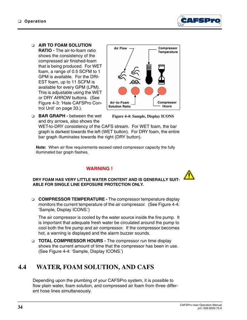
❑ AIR TO FOAM SOLUTION RATIO - The air-to-foam ratio shows the consistency of the compressed air finished-foam that is being produced. For WET foam, a range of 0.5 SCFM to 1 GPM is available. For the DRI-EST foam, up to 11 SCFM is available for every GPM (LPM). This is adjustable using the WET or DRY ARROW buttons. (See Figure 4-3: ‘Hale CAFSPro Con-trol Unit’ on page 33.).
❑ BAR GRAPH - between the wet and dry arrows, also shows the WET-to-DRY consistency of the CAFS stream. For WET foam, the bar graph is darkest towards the left (WET button). For DRY foam, the entire bar graph illuminates towards the right (DRY button).
Note: When air flow requirements exceed rated compressor capacity the fully illuminated bar graph flashes.
WARNING !
DRY FOAM HAS VERY LITTLE WATER CONTENT AND IS GENERALLY SUIT-ABLE FOR SINGLE LINE EXPOSURE PROTECTION ONLY.
❑ COMPRESSOR TEMPERATURE - The compressor temperature display monitors the current temperature of the air compressor. (See Figure 4-4: ‘Sample, Display ICONS.’)
The air compressor is cooled by the water source inside the fire pump. It is important that adequate fresh water be circulated around the pump to cool both the fire pump and air compressor. If the compressor becomes hot, a warning is displayed and the alarm buzzer sounds.
❑ TOTAL COMPRESSOR HOURS - The compressor run time display shows the current amount of time that the compressor has been in use. (See Figure 4-4: ‘Sample, Display ICONS.’)
4.4 WATER, FOAM SOLUTION, AND CAFS
Depending upon the plumbing of your CAFSPro system, it is possible to flow plain water, foam solution, and compressed air foam from three differ-ent hose lines simultaneously.
Figure 4-4: Sample, Display ICONS

Operation ❑
35CAFSPro User Operation Manualp/n: 029-0020-75-0
There are three critical items in the water flow path from the intake side of the pump and finally out of a hose line, i.e., the fire pump, the foam concen-trate injection point, and finally, the air injection point.
The Hale CAFSPro system uses integrated check valves, constructed of stainless steel, between all three points. The check valves ensure that at no point can air or foam concentrate flow back into the fire pump. This is very important as foam contamination of the water tank or portable municipal water supplies is a serious hazard to avoid.
When the CAFSPro system is ON, any discharge that is piped between the:
❑ Fire pump and the foam injection point will always be able to flow plain water.
❑ Foam injection point and the air injection point will always be able to flow foam solution.
❑ Air injection point and the discharge valves will always be able to flow compressed air foam.
When the CAFSPro air compressor is shut OFF, the CAFS and foam capa-ble discharges flow foam solution. When the FoamLogix proportioner is shut OFF, all the foam capable discharges revert to water operation.
It is important to understand the limitations of the CAFSPro system depend-ing upon the manifold installed. The foam solution and compressed air foam manifold is designed to flow at a specific flow rate. Generally, a maxi-mum of 750 or 1,000 GPM (2,839 or 3,785 LPM) of foam solution (liquid) is specified.
4.5 CREATING FINISHED FOAMS
The Hale CAFSPro is able to provide a wide range of compressed air foam consistencies and foam solution flow rates to meet most operational needs. If your system is equipped with a dual tank foam reservoir and a dual tank switch, your new foam pumper can handle most Class “A” and Class “B” foam agents. Use the recommended foam chemical percentage (%) listed for the foam concentrate.
Operation
When the pump is initially engaged, the foam injection and air injection sys-tems are powered up, the tank-to-pump valve is opened and the air com-pressor clutch is engaged.

❑ Operation
36CAFSPro User Operation Manual
p/n: 029-0020-75-0
Five seconds after system activation the tank-to-pump valve can be oper-ated manually – CLOSED by the operator. When a CAFS line is pulled and its corresponding discharge valve is opened, compressed air foam is avail-able at CAFS hose line.
Adjusting foam consistency from extremely WET to “shaving cream DRY” is done by pressing the WET or DRY ARROW buttons (to adjust the air-to-water ratio). The system starts at WET attack CAFS foam of 0.5 SCFM air to 1.0 GPM (3.8 LPM) solution.
However, it is important to note that the Hale CAFSPro uses a three-setting valve to create its wide range of foam types. When adjusting from the WET to MEDIUM range, the system beeps three (3) times. To make sure the sys-tem changes over to MEDIUM, the operator must hold down the button for the full duration of three beeps.
The available water volume through the foam manifold is reduced from 1,000 GPM (3,785 LPM) to about 300 GPM (1,136 LPM). Note that this affects all Compressed Air Foam lines.
Also when moving from the MEDIUM to DRY, the total water volume from all compressed air foam lines drops to around 30 GPM (114 LPM).
WARNING !
IT IS IMPERATIVE NEVER TO CHANGE TO “DRY FOAM” IF FIREFIGHTERS ARE ATTACKING A FIRE WITH A CAFS HOSE LINE. THE TOTAL VOLUME FROM ALL THE CAFS LINES COMBINED IS NO MORE THAN 30 GPM (114 LPM). USE THE “DRY” MODE ONLY WHERE APPROPRIATE, AND FIRE FIGHTER SAFETY WILL NOT BE COMPROMISED.
EXTREMELY DRY FOAM IS TYPICALLY USED FOR A SINGLE HAND LINE FOR EXPOSURE PROTECTION OR SOMETIMES FOR OTHER NON-FIRE ATTACK USES.
DRY FOAM CONTAINS VERY LITTLE WATER CONTENT AND IS NOT REC-OMMENDED FOR MULTIPLE LINE USE OR DIRECT FIRE ATTACK.
For foam solution only without air, set the air compressor in the STANDBY mode. Press the POWER button for about one (1) second until it beeps once. The air injection valve CLOSES and all compressed air foam lines become foam solution lines. The indicator light, under the ON button turns OFF.
Pressing the POWER button again shifts the CAFS system out of STANDBY to resume normal CAFS operations. This indicator light turns ON to indicate the system status.

Operation ❑
37CAFSPro User Operation Manualp/n: 029-0020-75-0
Compressor
The compressor is powered by the fire pump gear box. An air clutch auto-matically engages when the gear box is shifted from ROAD to PUMP.
The clutch engagement:
❑ Allows the production of instant compressed air foam from the time the first hand line is opened
❑ Provides a means of controlling the air compressor
The compressor is water cooled, using water from the fire pump. It is impor-tant to maintain pump circulation in order to avoid overheating the fire pump and compressor.
Also, when the compressor is in STANDBY mode, the clutch is still engaged and the compressor is still turning. This allows the air to return on-line at a moment’s notice with a touch of a button. However, if you press and hold down the POWER button on the air injection controller for a full six seconds and through the beep warning process, the air compressor clutch disen-gages and the compressor shuts down.
Note: Before the clutch disengages the display beeps a warning, and counts down OFF3...OFF2…OFF1, only then does the clutch disengage. If you release the POWER button before or during this warning the clutch does not disengage. To power the compressor back on, the fire pump must be throttled down to IDLE rpm and the pump disengaged, and then reengaged to restart the cycle.
CAUTION !
DO NOT DISENGAGE THE FIRE PUMP WHILE THE TRUCK TRANSMISSION IS IN GEAR. SHIFT TO “NEUTRAL” AND WAIT FOR THE DRIVE SHAFT TO “STOP.” FOLLOW MIDSHIP PUMP SHIFT PROCEDURES IN THE APPROPRI-ATE MANUAL. DO NOT RUN CAFS ABOVE 150 PSI (10.3 BAR). IF TRUCK IS TO BE USED AS A WATER SUPPLY UNIT AT PRESSURES ABOVE 150 PSI (10.3 BAR), YOU MUST DISENGAGE COMPRESSOR CLUTCH.
Tanks
If so equipped, your truck could have either an “air dual tank switch” (ADT) or a “manual dual tank” valve (MDT). Your truck could also have both an A foam reservoir and a B foam reservoir. Use an approved Class “A” foam concentrate in the A tank and approved Class “B” foam concentrate in the B tank. This provides maximum flexibility in dealing with various fire hazards.

❑ Operation
38CAFSPro User Operation Manual
p/n: 029-0020-75-0
To operate the ADT, simply switch the toggle switch between positions A and B, passing the “FLUSH” or center position. An indicator light illumi-nates next to the position selected indicating the change has been success-ful. The ADT flushes the foam concentrate manifold when you pause between foam types to prevent congealing that occurs when Class “A” and Class “B” foam concentrates mix.
Turn manual dual tank lever from the A to the B position with a pause in the FLUSH position for about 5-10 seconds. When using Class “B” foam, pull the lever back into the FLUSH position and flush the foam system to ensure that all of the Class “B” foam is washed out of the foam pump. Then move the lever to the A position and run the system until Class “A” foam solution flows out of the discharges.
CAUTION !
DO NOT MIX TYPES OR BRANDS OF FOAM CONCENTRATES IN THE FOAM TANK.
With an approved Class “A” foam concentrate, keep the system in “A tank mode,” ready for immediate use.
Many foam manufacturers recommend that you use the foam system every 30-60 days to prevent foam chemical jelling or hardening. Check with the foam concentrate manufacturer. If the truck is going to storage, flush the foam pump and leave in flush mode.
4.6 CAFSPRO SAFETY PROTOCOLS
Although the Hale CAFSPro is fully integrated and safety-engineered, there are still system warnings built in and fire ground practices that firefighters and pump operators must follow to ensure safety.
WARNINGS !
WHEN THE PUMP IS IN GEAR, THE TANK-TO-PUMP VALVE IS AUTOMATI-CALLY ENGAGED. THIS RESULTS IN THE VALVE HANDLE MOVING AWAY FROM THE PUMP PANEL TO ITS FULLY EXTENDED LENGTH OF APPROXI-MATELY 12” (305MM). KEEP THIS AREA CLEAR OF PERSONNEL AND OBSTRUCTIONS.
DO NOT USE CAPS ON COMPRESSED AIR FOAM DISCHARGES. COM-PRESSED AIR STORES ENERGY AND CAN BE DANGEROUS IF A CAP IS REMOVED WHILE A VALVE IS OR WAS OPENED.

Operation ❑
39CAFSPro User Operation Manualp/n: 029-0020-75-0
For your safety, Hale has designed a self-bleed mechanism into the CAFS manifold. As a precaution against air-energized manifolds, when the pump is switched back to ROAD, the CAFS manifold drains itself, then the drain automatically closes. The manifold is still WET and can even contain some residual pressure, but the higher pressures and stored energy have been safely drained to the ground.
Note: Every time the pump is shifted back to ROAD, a small discharge of water solution is drained under the truck.
In addition, numerous electronic and mechanical safety features have been designed into the CAFSPro as follows:
❑ If the FoamLogix detects a loss of foam concentrate prime resulting in no concentrate flowing into the foam manifold, it automatically disengages the air injection to prevent “slug flow.”
❑ “Low foam” flashes if FoamLogix detects that there is a dangerously low level of concentrate in the foam reservoirs.
❑ If the FoamLogix is accidentally powered OFF, or the operator turns OFF the foam injection system before the air injection system, the air injection system automatically is disengaged to prevent “slug flow.”
❑ The compressed air injection system’s safety features are to alert the operator of:
● Dangerously high compressor temperatures
● Dangerously high rotary compressor speed. If the operator over-revs the throttle, a warning will flash and sound.
❑ If the operator continues to increase speed, the compressor disengages. CAFSPro systems must not be run above 150 PSIG. This eliminates most high speed issues.
4a Operating Procedures
IMPORTANT !
THIS MANUAL COVERS BASIC OPERATION OF THE HALE CAFSPRO SYS-TEM INSTALLED ON THE APPARATUS AND RELATED SUBSYSTEMS. FOR DETAILED OPERATION AND MAINTENANCE INSTRUCTIONS OF THE APPA-RATUS AND FIRE PUMP, REFER TO THE INDIVIDUAL MANUALS SUPPLIED WITH THE THESE COMPONENTS. INDIVIDUAL MANUALS CONTAIN MORE DETAILED INFORMATION.

❑ Operation
40CAFSPro User Operation Manual
p/n: 029-0020-75-0
IMPORTANT ! - continued
A COMPRESSED AIR FOAM SYSTEM (CAFS) IS A VALUABLE FIRE FIGHTING TOOL. HOWEVER, PROPER OPERATION AND TACTICAL USE MUST BE ADDRESSED THROUGH TRAINING AND EDUCATION.
THIS MANUAL COVERS THE BASIC OPERATION OF THE HALE CAFSPRO SYSTEM AND DESCRIBES A BASIC SYSTEM ONLY. FURTHER EDUCATION AND TRAINING ON FOAM AND COMPRESSED AIR FOAM IS REQUIRED FOR EFFECTIVE AND SAFE FIRE FIGHTING USE OF THIS EQUIPMENT.
WARNING !
BEFORE ATTEMPTING TO START THE HALE CAFSPRO SYSTEM, MAKE SURE TO CLOSE ALL DRAINS AND DISCHARGE VALVES.
ATTACK HOSES SHOULD BE APPROVED FOR USE WITH CAFS SYSTEMS. REFER TO HALE BULLETIN #686 FOR A LISTING OF ATTACK HOSES APPROVED BY HOSE MANUFACTURERS FOR USE WITH HALE CAFSPRO SYSTEMS.
MAKE SURE PROPER PERSONAL PROTECTIVE EQUIPMENT (PPE) IS USED WHEN OPERATING THE APPARATUS.
WET SURFACES ON THE APPARATUS BECOME SLIPPERY. USE CARE WHEN CLIMBING ON THE APPARATUS DURING OPERATIONS.
4A.1 WATER SUPPLY
The water supply for the apparatus fire pump, when operating the Hale CAFSPro system, could come from the booster tank (gravity feed), drafting from a water source, or a pressurized source like a hydrant or another fire pump. Follow all industry guidelines and training for water supply to the apparatus.
CAUTION !
THE FIRE PUMP IS EQUIPPED WITH A MECHANICAL SEAL. DO NOT RUN THE PUMP DRY FOR EXTENDED PERIODS OF TIME OR SEAL DAMAGE COULD RESULT.
When operating from a positive pressurized water source, use the relief valve to maintain pressure and proper engine RPM. If incoming water pres-sure is excessively high, it may not be possible to maintain engine RPM and desired pressure.

Operation ❑
41CAFSPro User Operation Manualp/n: 029-0020-75-0
When a suitable booster tank with direct fill is available, running the pressur-ized water source into the tank, and running the CAFSPro system while tak-ing suction from the tank, eliminates the problem of higher water pressure than desired.
Gating the pump discharges reduces hand line pressure when water is flow-ing. However, when the nozzle is closed momentarily, line pressures rise to meet master pump pressure. This makes nozzle reaction excessive when the nozzle is again opened.
Figure 4-5: CAFSPro Typical Operating Ranges
Note: CAFS hose lines store energy in compressed air when the nozzle is closed and, nozzle reaction, when opened, can be severe.
WARNING !
DO NOT USE AN AUTOMATIC PRESSURE GOVERNOR IN PRESSURE CON-TROL MODE WITH CAFS. THE PRESSURE GOVERNOR RESPONDS TO CHANGES IN PRESSURE AND COULD, WITHOUT WARNING, REDUCE ENGINE SPEED. THIS REDUCTION IN SPEED COULD REDUCE THE AVAIL-ABLE AIR CAPACITY OF THE CAFS SYSTEM.
INADEQUATE AIR SUPPLY CREATES AN INEFFECTIVE FIRE FIGHTING STREAM THAT COULD PLACE FIRE CREWS AT GREATER RISK.
ALWAYS OPEN NOZZLES SLOWLY WHEN FLOWING A CAFS HOSE LINE TO PREVENT EXCESSIVE NOZZLE REACTION FORCE. ALSO SEE SECTION 1 “SAFETY PRECAUTIONS” ON PAGE 7.
Note: The compressor clutch engages when the pump shifts from ROAD to PUMP.
PumpModel
RatioEngineRPM
PressurePSI (Bar)
QMAX23 1050 100 (7)
21 1170 100 (7)
QPAK23 1155 100 (7)
21 1285 100 (7)
QFLO23 1709 100 (7)
21 1235 100 (7)

❑ Operation
42CAFSPro User Operation Manual
p/n: 029-0020-75-0
Engage Pump
1. Once water supply is established, shift the apparatus from ROAD to PUMP using approved departmental procedures.
2. Shifting to PUMP also opens the tank to pump valve, engages the FoamLogix and CAFSPro systems, and the compressor clutch.
Establish Discharge Pressure
1. With the system engaged, operate the apparatus as you would during normal water pump operation.
2. Bring the water master dis-charge pressure up to a suit-able pressure [100 PSIG (7 BAR)].
3. The master air pressure nee-dle (RED) follows or tracks the water pressure needle (BLACK) to within 5 PSI (0.4 BAR).
Note: The relief valve indicator must be OFF. If it is ON, turn the relief valve handle clockwise until the indicator is OFF.
WARNING !
IF THE APPARATUS IS EQUIPPED WITH AN ELECTRONIC GOVERNOR, PLACE THE GOVERNOR IN RPM MODE DURING CAFS OPERATIONS.
DO NOT EXCEED 150 PSI (10.3 BAR) WITH THE AIR COMPRESSOR ENGAGED.
4. Compressed air adds horsepower to the fire fighting stream. Hand line pressures above 125 PSIG (9 BAR) are generally not required and can cause excessive nozzle reaction force.
Figure 4-6: Master Gauge CAFSPro Pressure Range

Operation ❑
43CAFSPro User Operation Manualp/n: 029-0020-75-0
WARNING !
CAFS SYSTEMS ADD POWER TO THE FIRE STREAM VIA COMPRESSED AIR. PROPER EDUCATION, TRAINING AND NOZZLE SELECTION IS REQUIRED FOR OPERATIONAL EFFECTIVENESS AND SAFETY. NOZZLE REACTION GREATER THAN THAT OF PLAIN WATER IS TO BE EXPECTED.
Set Relief Valve
(See Figure 4-7: ‘Relief Valve Control.’)
1. When operating from draft, or the apparatus booster tank, the engine maintains correct speed for proper air compressor operation.
2. When operating from a pressurized water source it is necessary to set the fire pump relief valve to maintain the correct water discharge pressure of:
❑ 90-100 PSI (6 to 7 BAR)] for hand lines
❑ 125-150 PSI (9 to 10 BAR) for master streams and proper engine speed for air compressor operation.
3. With the master discharge pressure gauge showing the correct discharge pressure, set the Hale Total Pressure Master Relief Valve. Turn the han-dle counterclockwise until the BLACK needle on the gauge drops and the indicator on the relief valve nameplate lights.
4. Next, turn handle clockwise until the BLACK needle returns to the required pressure setting and the indicator light turns OFF.
5. Turn the handle an additional half-turn clockwise. The valve is now properly set.
6. Adjust the hand throttle to set the engine speed in the optimum range for CAFS operation. Discharge pressure must remain at the present set-ting.
7. Excessive intake pressures prevent achieving optimum engine speed without excessive discharge pressures.
Figure 4-7: Relief Valve Control

❑ Operation
44CAFSPro User Operation Manual
p/n: 029-0020-75-0
Note: A direct tank fill separates the pump intake from the positive supply pres-sures and allows the pump and CAFS to operate independently of the high pres-sure supply for easier operations. Hale offers an automatic direct tank fill that allows continuous operation without operator action.
Open Discharge Valve(s)
Open the discharge valve(s) to charge the discharge line(s).
Open CAFS Discharge
Slowly open the nozzle on the CAFS hose line to begin compressed air foam fire operation.
The LEDs on the FoamLogix and CAFSPro control units turn ON to indicate foam concentrate and air injection.
Check FoamLogix and Air Flow Readings
1. With the nozzle open the system discharges compressed air foam. The FoamLogix display shows the foam solution flow rate in the CAFS capa-ble discharge(s).
2. The CAFSPro display shows the air flow rate in SCFM.
3. The duplex master pressure gauge needles (RED and BLACK) do not necessarily match when CAFS discharge(s) are open.
4. Typically, air pressure is less than the water pressure when flowing. For example, when the indicator is at the full WET 0.5% position, the follow-ing readings are shown on the various displays:
Duplex Master Pressure Gauge
❑ Water, black needle..........................................100 PSIG (7 BAR)
❑ Air, red needle ....................................................85 PSIG (6 BAR)
Note: With the CAFS discharge closed (or nozzle shut), the two needles (air and water) on the master duplex pressure gauge should match, within 5 PSI (0.4 BAR).
Hale FoamLogix Control Unit
❑ Water Flow ..................................................... 95 GPM (360 LPM)

Operation ❑
45CAFSPro User Operation Manualp/n: 029-0020-75-0
Hale CAFSPro Display Unit
❑ Air Flow....................................................... 70 SCFM (50 NCMH)
Wet and Dry Foam
When the CAFSPro system is energized the CAFSPro display unit is set for WET 0.5% attack foam – a concentrate of approximately 0.5 SCFM (0.3 NCMH) air to 1.0 GPM (3.8 LPM) foam solution.
The foam type is adjustable from WET (0.5%) to DRY (11.0%) by pressing the DRY button. Three stages of CAFS are available:
❑ WET 0.5% to 1.5%
❑ MEDIUM 1.75% to 3.0%
❑ DRY 11.0%
The DRY button must be held for several seconds for the changeover to occur. The display shows CFLO and the audible alarm beep sounds when the changeover is complete.
When shifting from MEDIUM to DRY the foam concentrate injection rate automatically sets to 1.0%, to produce a drier finished compressed air foam. When shifting back to MEDIUM, the foam injection rate switches back to 0.5%, or the initial value prior to switch.
4b CAFS Operation Summary
4B.1 PROCEDURE
The following is a summary of the steps required for normal CAFS system operation.
1. Connect (supply) suction hoses, layout discharge hoses.
2. Establish water supply.
3. Engage apparatus fire pump for operation. Prime the water pump.
4. Increase apparatus engine speed until desired discharge pressure is attained (for example, 100 PSIG (7 BAR).

❑ Operation
46CAFSPro User Operation Manual
p/n: 029-0020-75-0
Note: Set electronic governor to RPM mode during CAFS operation.
5. Open discharge valve to charge CAFS hose line with water.
6. Slowly open CAFS hose nozzle to begin CAFS operations.
7. Monitor water and air flows and pressures.
8. Adjust apparatus throttle to maintain safe CAFS discharge of about 100 to 125 PSI (6.9 to 8.6 BAR) pressure.
9. Adjust foam consistency (WET to DRY) by pressing UP or DOWN ARROW buttons on the CAFSPro display to the required foam dis-charge.
4B.2 CAFS SYSTEM MESSAGES
The following messages could appear on the CAFSPro display to notify the operator of specific conditions during normal operation:
❑ CAFS - System is ready for operation without flow
❑ STB4 - Air injection OFF; clutch is ENGAGED
❑ OFF3, OFF2, OFF1 - Displayed during manual system shut down. ON button must be held.
❑ OFF - Compressor
❑ PUEN - Attempting to engage clutch with pump engaged and high RPM.
❑ PSI - System in MANUAL pressure mode.
❑ COLD - Compressor air temperature below sensor range.

System Shutdown ❑
47CAFSPro User Operation Manualp/n: 029-0020-75-0
5 System Shutdown
Proper shutdown procedures prolong the life of the CAFSPro system and ensure the system is ready for operation when needed.
5.1 FOR SYSTEM SHUTDOWN
1. Turn the air injection OFF by pressing the i (ON) button on the CAFSPro control unit.
The display reads STBY.
2. Turn the Hale FoamLogix foam proportioning system OFF by pressing the i button on the control unit. Also see FoamLogix Operation and Maintenance Manual, Hale p/n: 029-0020-68-0.
Note: If Class “B” foam concentrate was used during operations, flush the Hale FoamLogix using procedures in the operation section of the Hale FoamLogix Operation and Maintenance Manual, Hale p/n: 029-0020-68-0.
Return selector to Class “A” position.
3. Flush all hoses clear of all foam residue.
Establish water flow through the CAFS and/or foam solution hose lines and flush until discharge is clear.
4. Close discharge valves.
WARNING !
ALWAYS OPEN NOZZLES SLOWLY WHEN FLOWING A CAFS HOSE LINE. ADDING COMPRESSED AIR TO THE HOSE LINE DRAMATICALLY INCREASES THE ENERGY CONTENT. HOSE LINES CHARGED WITH COM-PRESSED AIR FOAM HAVE VERY LITTLE WEIGHT BUT CONTAIN LARGE AMOUNTS OF ENERGY. NOZZLE REACTION GREATER THAN THAT OF PLAIN WATER IS TO BE EXPECTED.
IT IS ACCEPTABLE TO LEAVE THE FOAM SELECTOR IN THE CLASS “A” POSITION. WHEN APPROVED CLASS “A” FOAMS ARE USED READ AND FOLLOW THE MANUFACTURER’S DIRECTIONS ON FREQUENCY OF USE TO AVOID SYSTEM PROBLEMS.

❑ System Shutdown
48CAFSPro User Operation Manual
p/n: 029-0020-75-0
5. Shift pump from PUMP to ROAD mode.
6. The discharge manifold drain opens long enough (approximately 10 seconds) to drain some residual pressure from the manifold. The pump remains left wet.
Note: The tank-to-pump valve CLOSES automatically.
7. Shut OFF the apparatus and perform scheduled maintenance and stow-age of equipment.
8. Drain pump if SOPs require it.
WARNING !
PROJECTILES CAN CAUSE INJURY. DO NOT USE A BLANK HOSE CAP ON CAFS DISCHARGES. CAFS SYSTEMS STORE ENERGY IN PIPING THAT COULD TURN A BLANK HOSE CAP INTO A PROJECTILE WHEN REMOVED.
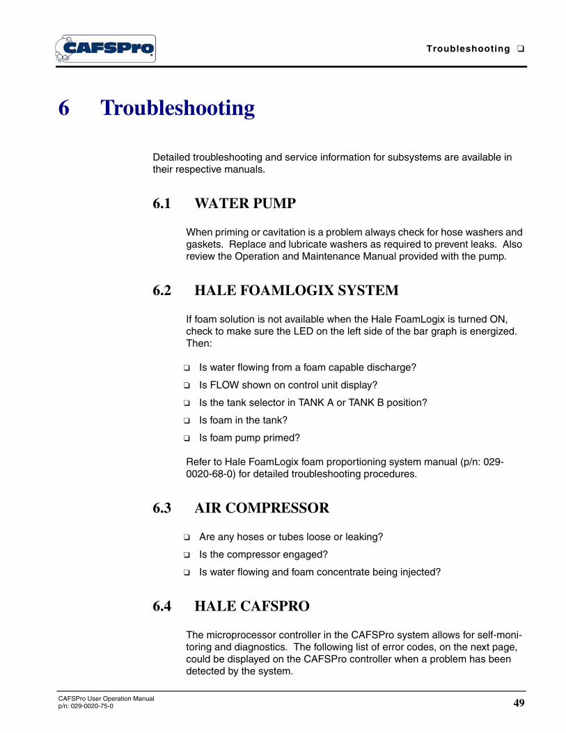
Troubleshooting ❑
49CAFSPro User Operation Manualp/n: 029-0020-75-0
6 Troubleshooting
Detailed troubleshooting and service information for subsystems are available in their respective manuals.
6.1 WATER PUMP
When priming or cavitation is a problem always check for hose washers and gaskets. Replace and lubricate washers as required to prevent leaks. Also review the Operation and Maintenance Manual provided with the pump.
6.2 HALE FOAMLOGIX SYSTEM
If foam solution is not available when the Hale FoamLogix is turned ON, check to make sure the LED on the left side of the bar graph is energized. Then:
❑ Is water flowing from a foam capable discharge?
❑ Is FLOW shown on control unit display?
❑ Is the tank selector in TANK A or TANK B position?
❑ Is foam in the tank?
❑ Is foam pump primed?
Refer to Hale FoamLogix foam proportioning system manual (p/n: 029-0020-68-0) for detailed troubleshooting procedures.
6.3 AIR COMPRESSOR
❑ Are any hoses or tubes loose or leaking?
❑ Is the compressor engaged?
❑ Is water flowing and foam concentrate being injected?
6.4 HALE CAFSPRO
The microprocessor controller in the CAFSPro system allows for self-moni-toring and diagnostics. The following list of error codes, on the next page, could be displayed on the CAFSPro controller when a problem has been detected by the system.
❑ Troubleshooting
50CAFSPro User Operation Manual
p/n: 029-0020-75-0
CAFSPro Error Codes
can .............. //No messages from FoamLogix.
This is normal if the FoamLogix is not powered up or the truck batteries were just turned ON.
aflo ..............//Air flow too low for running conditions. If this message persists, it could indicate faulty wiring connections.
lo p ..............//Air pressure is too low.
hi p ..............//Air pressure is too high.
hicp .............//Compressor temperature too high.
aerr .............//Air flow sensor error.
epcp EEpr ...//EEprom on CAFSPro has and error indication.
bdCd ...........//Bad password entered.
Wait for password to clear itself and try to enter password again.
lo f ...............//Foam tank running low.
nopr.............//Foam motor has not achieved prime or lost prime.
flsh ..............//FoamLogix in FLUSH mode.
Air is not injected with the FoamLogix in FLUSH mode to avoid “slug flow” and “chatter.”
hifl ...............//Foam motor is hot.
epfl ..............//EEProm on foam control bad
Nloc.............//Failed to achieve lock in a reasonable time.
This is an indication of a possible air leak or clog in the pneumatic control plumbing on the CAFSPro compressor intake valve.
losp .............//Supply voltage is low (<11.2 Volts).
SDHI ...........//RPM maximum has been reached.
High Air Pressure
Overfilling the oil in the compressor system or allowing excessive moisture or water in the separator tank can lead to pressures that increase to 150 or 175 PSI (10 to 12 BAR). If this occurs, contact Hale Service at 1-610-825-6300 for service kit # S56-0000-00-0.
Low Air Flow/Poor Quality Dry Foam
Poor quality “dry” foam my be caused by LOW engine speeds (RPM). Tak-ing high inlet pressure from a hydrant or relay can keep the engine speed to low, causing LOW air flow. (See Figure 4-5: ‘CAFSPro Typical Operating Ranges’ on page 41.)

Routine Maintenance ❑
51CAFSPro User Operation Manualp/n: 029-0020-75-0
7 Routine Maintenance
Between operations of the CAFSPro make sure system components are filled with the proper grade and amount of oil. These components include the Air Compres-sor System and Drive Unit Gearbox.
The following procedures are provided to assist in the periodic maintenance of oil levels. For detailed maintenance instructions of individual components, refer to the maintenance and operation manuals that were supplied with the apparatus.
Service should be performed by a trained and qualified service technician, or your authorized Hale Products service representative. Be sure you have sufficient knowledge, experience, the proper tools and Hale genuine replacement parts before you attempt any repair maintenance.
For an illustrated CAFSPro system, see Figure 2-4: “CAFSPro Pump System Over-view” on page 19.
WARNING !
DO NOT PERFORM MAINTENANCE ON THE CAFSPRO SYSTEM WHILE THE APPARATUS IS RUNNING. MAKE SURE THE APPARATUS IS SHUT DOWN AND COMPONENTS HAVE COOLED BEFORE ATTEMPTING MAINTENANCE.
THE PROPER OIL LEVEL MUST BE MAINTAINED IN THE AIR COMPRESSOR SYSTEM AT ALL TIMES. LOW OIL LEVEL OR NO OIL COULD RESULT IN EXCESSIVE COMPRESSOR TEMPERATURE AND MAJOR DAMAGE. HIGH OIL LEVEL COULD CAUSE THE CONTROL SYSTEM TO MALFUNCTION OR CAUSE A DRIVE FAILURE.
7.1 AIR COMPRESSOR MOISTURE DRAIN
After the air compressor system is used and has had time to COOL to ambi-ent temperature, accumulated moisture must be drained from the oil reser-voir separator.
Drain Moisture
(See Figure 7-1: ‘Maintenance Overview’ on page 52.)
1. To drain the moisture from the system, locate the oil and moisture drain valve on the bottom of the oil reservoir separator.

❑ Routine Maintenance
52 CAFSPro User Operation Manualp/n: 029-0020-75-0
Figure 7-1: Maintenance Overview
2. Place a suitable container 8 to 10 ounces (237 to 296 ml) under the compressor drain valve and remove the brass valve plug. (See Figure 7-1: ‘Maintenance Overview.’)
3. Open the valve and allow the water to drain. The oil drain valve is a 1/4” NPT ball valve.
Monitor the flow. As soon as pure oil begins flowing, CLOSE the valve.
4. Replace the brass valve plug in the valve and check the oil level.
IMPORTANT !
DISPOSE OF THE WASTE WATER/OIL IN ACCORDANCE WITH YOUR LOCAL RECYCLING REGULATIONS.
Note: In humid weather, after short run times, up to 8 ounces (237 ml) of conden-sation could accumulate. Running the compressor for a longer period automati-cally removes the moisture through the discharge with the air and heating of the oil.

Routine Maintenance ❑
53CAFSPro User Operation Manualp/n: 029-0020-75-0
7.2 OIL AND OIL FILTER
The air compressor oil and oil filter must be changed every 100 hours of operation or when the apparatus engine oil is changed.
To Change Oil and Oil Filter
1. Locate the oil reservoir separator and air compressor oil filter on the apparatus. (See Figure 7-1: ‘Maintenance Overview’ on page 1-52.)
Also see CAFSPro Installation Guide, p/n: 029-0020-78-0, Section 5 “System Oil Fill,” on page 47, for additional information.
2. Place a waste container below the drain valve to catch the oil or mois-ture as it drains. The container must have sufficient capacity to hold the drained oil, approximately 8 to 9 quarts (7.5 to 8.5 liters).
3. Remove the valve plug and OPEN the valve to drain all oil.
4. When all oil has drained from the system, CLOSE the valve and REPLACE the valve plug.
5. Place the waste container under the oil filter and unscrew the filter from its mount adapter. An oil filter strap-wrench might be necessary to loosen the filter.
6. Drain remaining oil from the filter.
IMPORTANT !
DISPOSE OF THE WASTE WATER/OIL AND OIL FILTER IN ACCORDANCE WITH YOUR LOCAL RECYCLING REGULATIONS.
7. Obtain a new Fram HP-6 oil filter (Hale p/n: 010-0650-01-0). Before installing new filter, fill the filter approximately 1/2 full with SAE 15W-40HD oil and lightly coat the filter gasket with SAE 15W-40HD oil.
Note: The oil filter (Hale p/n: 010-0650-01-0) is a Fram HP-6 model filter. The oil filter must have a 200 PSI (14 BAR) pressure rating. DO NOT use a substitute type or brand of filter without first checking for a 200 PSI (14 BAR) pressure rat-ing. Also see CAUTION! on page 54.

❑ Routine Maintenance
54 CAFSPro User Operation Manualp/n: 029-0020-75-0
CAUTION !
USE THE EXACT REPLACEMENT OIL FILTER. OTHER FILTER TYPES MAY NOT WITHSTAND THE SYSTEM PRESSURE AND OIL FILTER FAILURE COULD LEAD TO A MAJOR COMPRESSOR FAILURE.
8. Screw the new oil filter onto the oil filter adapter being careful not to cross thread the filter.
Initially tighten the filter hand-tight, then tighten an additional 1/2 to 3/4 turn using an oil filter wrench.
9. Remove the oil fill plug from the fill pipe located on the oil reservoir sep-arator.
10. Refill system with oil. The system requires approximately 8 to 9 quarts (7.5 to 8.5 liters) of SAE 15W-40HD motor oil. The proper oil level is when oil is visible in 1/2 to 3/4 of the sight gauge when the compressor is NOT running.
WARNING !
ALWAYS ALLOW OIL TO SETTLE PRIOR TO CHECKING LEVEL. DO NOT OVERFILL THE SYSTEM.
THE PROPER OIL LEVEL MUST BE MAINTAINED IN THE AIR COMPRESSOR SYSTEM AT ALL TIMES. LOW OIL LEVEL OR NO OIL COULD RESULT IN EXCESSIVE COMPRESSOR TEMPERATURE AND MAJOR DAMAGE. HIGH OIL LEVEL COULD CAUSE THE CONTROL SYSTEM TO MALFUNCTION OR A DRIVE FAILURE.
11. When the system is filled to the proper level, check and clean the O-ring seal on the fill plug, then replace the plug. DO NOT over-tighten.
WARNING !
WHEN STARTING CAFSPRO UNIT DURING MAINTENANCE, MAKE SURE ALL TOOLS AND LOOSE CLOTHING ARE KEPT AWAY FROM ROTATING COMPONENTS. KEEP HANDS, FACE AND ARMS AWAY FROM ROTATING COMPONENTS WHILE SYSTEM IS OPERATING. ALSO SEE SECTION 1 “SAFETY PRECAUTIONS” ON PAGE 7.
12. Start the system and energize the air compressor to allow pressure to build and circulate oil through the hoses.

Routine Maintenance ❑
55CAFSPro User Operation Manualp/n: 029-0020-75-0
DO NOT allow the system to operate for more than 30 seconds. While the system is running check for leaks at the oil filter, drain plug and fill plug.
13. Shut down the system and allow the air compressor oil to settle.
14. Check oil level and add oil as necessary until oil is visible in 1/2 to 3/4 range of the sight gauge tube.
15. Shut down the system.
7.3 COMPRESSOR CLUTCH GREASE
(See Figure 7-1: ‘Maintenance Overview’ on page 52.)
Grease should be injected into the compressor clutch housing when “Annual” apparatus maintenance is performed.
1. The compressor clutch grease fitting is located on the clutch, near the bearing housing. (See Figure 7-1: ‘Maintenance Overview’ on page 52.)
2. Remove customer installed interferences to gain access to this fitting.
3. Using a grease gun, inject approximately 2 oz. (59ml) of MOBILE Hi Temperature GREASE 28 into the grease fitting.
DO NOT USE CHASSIS LUBE.
4. Replace interferences that were removed in preceding Step 2.
7.4 COOLING WATER STRAINER
The stainless steel mesh strainers prevent any solids or debris in the pump water from passing into the heat exchanger where they can clog and lead to overheating and serious damage. They can be easily cleaned using warm water, and/or then replaced.
WARNING!
DO NOT REMOVE STRAINER CAP WHILE PUMP IS RUNNING.
The strainer should be cleaned and checked after each use or every month. The 1-1/2” NST Cap is usually located on the passenger side of the apparatus.

❑ Routine Maintenance
56 CAFSPro User Operation Manualp/n: 029-0020-75-0
1. The stainless steel mesh basket pulls out for cleaning.
2. Clean thoroughly using warm water. Replace if the screen is ripped or damaged. Order Hale p/n: 010-0670-00-0.
7.5 AIR CLEANER ELEMENT
Change the air cleaner element on the CAFSPro System every time the engine air filter is changed. Order Hale p/n: 010-0690-00-0.
7.6 COMPRESSOR BELT TENSION ADJUSTMENT
(See Figure 7-3: ‘Belt Tension Gauge’ on page 57.)
General
Proper belt tension is critical to long equipment life. A loose belt causes a knock or bang as the teeth jump. An over tightened belt overloads the bearings and leads to premature wear or failure.
For convenience, an adjust-ment clearance port in the belt guard cover is now pro-vided. If your system includes this feature, proceed to heading “To Check Ten-sion” on page 57.
If your belt guard does not have the adjustment clear-ance port the guard must be removed. See heading “Remove Belt Guard” below.
Remove Belt Guard
To expose the belt, the belt guard must be removed - 6 screws and hard-ware. (See Figure 7-2: ‘Removing the Belt Guard.’)
Figure 7-2: Removing the Belt Guard

Routine Maintenance ❑
57CAFSPro User Operation Manualp/n: 029-0020-75-0
To Check Tension
Use a belt tension gauge to determine the tension applied to the belt and check on the left side of the unit. (See Figure 7-3: ‘Belt Tension Gauge.’)
When applying a load of 16 to 20 lbs. (7 to 9 kg.), perpen-dicular to the belt, the deflection should be no more than 5/16”(8mm).
If the deflection is more or less than 5/16” (8mm), follow the procedure below to tighten, respectively – loosen the belt to exert the neces-sary tension on the gauge. (See Figure 7-4: ‘Tension Gauge.’)
Note: The tension gauge shown is a Goodyear® Industries, Tension Tester. (Order from Hale Products, p/n: 029-0680-00-0.)
When the gauge is set perpendicular to the belt, use a refer-ence point on the body of the gauge that coincides with a mark on a scale (or a ruler), held in a fixed position next to the gauge.
Push gauge towards the belt until the body of the gauge moves 5/16” (8 mm) along the scale (or ruler). Remove the gauge and read the tension that the rubber O-ring marked. If tension is lower than 16 lbs. (7 kg.), the belt is loose; if the tension is greater than 20 lbs. (9kg.), the belt is too tight. (See Figure 7-4: ‘Tension Gauge.’)
Figure 7-3: Belt Tension Gauge
Figure 7-4: Tension Gauge
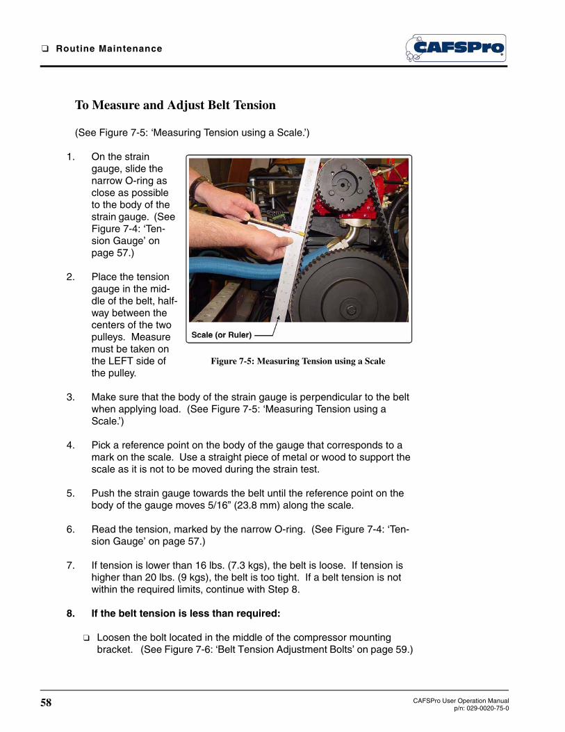
❑ Routine Maintenance
58 CAFSPro User Operation Manualp/n: 029-0020-75-0
To Measure and Adjust Belt Tension
(See Figure 7-5: ‘Measuring Tension using a Scale.’)
1. On the strain gauge, slide the narrow O-ring as close as possible to the body of the strain gauge. (See Figure 7-4: ‘Ten-sion Gauge’ on page 57.)
2. Place the tension gauge in the mid-dle of the belt, half-way between the centers of the two pulleys. Measure must be taken on the LEFT side of the pulley.
3. Make sure that the body of the strain gauge is perpendicular to the belt when applying load. (See Figure 7-5: ‘Measuring Tension using a Scale.’)
4. Pick a reference point on the body of the gauge that corresponds to a mark on the scale. Use a straight piece of metal or wood to support the scale as it is not to be moved during the strain test.
5. Push the strain gauge towards the belt until the reference point on the body of the gauge moves 5/16” (23.8 mm) along the scale.
6. Read the tension, marked by the narrow O-ring. (See Figure 7-4: ‘Ten-sion Gauge’ on page 57.)
7. If tension is lower than 16 lbs. (7.3 kgs), the belt is loose. If tension is higher than 20 lbs. (9 kgs), the belt is too tight. If a belt tension is not within the required limits, continue with Step 8.
8. If the belt tension is less than required:
❑ Loosen the bolt located in the middle of the compressor mounting bracket. (See Figure 7-6: ‘Belt Tension Adjustment Bolts’ on page 59.)
Figure 7-5: Measuring Tension using a Scale

Routine Maintenance ❑
59CAFSPro User Operation Manualp/n: 029-0020-75-0
❑ Tighten two jacking studs located at both ends of the com-pressor mounting bracket.
9. If the belt tension is tighter than required:
❑ Loosen two studs located at both ends of the com-pressor mounting bracket. Make sure that the two nuts are tight to the bracket. (See Figure 7-6: ‘Belt Tension Adjustment Bolts.’)
❑ Tighten bolt located in the middle of the compressor mounting bracket.
10. Repeat preceding Steps 2 through 6 to verify that the belt tension is within the required limits. Readjust accordingly.
11. Reinstall the belt guard and test run the system before returning the unit to service.
7.7 HOT SHIFT CLUTCH OPTION
(See Figure 7-7: ‘Hot Shift Oil Sight Tube’ on page 60.)
The hot shift clutch oil should be changed every 100 hours of operation or when the apparatus engine oil is changed.
To change oil...
1. Place a suitable container 12 to 14 ounces under the hot shift front clutch housing and remove the brass drain plug. (See Figure 7-7: ‘Hot Shift Oil Sight Tube’ on page 60.)
2. Drain all oil then reinstall the brass drain plug.
Figure 7-6: Belt Tension Adjustment Bolts

❑ Routine Maintenance
60 CAFSPro User Operation Manualp/n: 029-0020-75-0
IMPORTANT !
DISPOSE OF THE WASTE WATER/OIL IN ACCORDANCE WITH YOUR LOCAL RECYCLING REGULATIONS.
3. Remove the brass fitting, containing the air vent, from the fill tube hose barb. (See Figure 7-7: ‘Hot Shift Oil Sight Tube.’)
4. Using a squeeze bottle or funnel, refill the housing via the hose bar fitting and fill hose with Dexron III or Mercon ATF or equal, while watch-ing the oil level sight gauge. The housing holds approximately twelve (12) ounces (0.4 liters).
The proper oil level is when the oil level sight tube is filled half way between the top and bottom.
WARNING !
ALWAYS ALLOW OIL TO SETTLE PRIOR TO CHECKING LEVEL. DO NOT OVERFILL THE SYSTEM.
THE PROPER OIL LEVEL MUST BE MAINTAINED IN AT ALL TIMES. LOW OIL LEVEL OR NO OIL COULD RESULT IN EXCESSIVE OPERATING TEMPERA-TURES CAUSING MAJOR DAMAGE. HIGH OIL LEVEL COULD CAUSE THE SYSTEM TO MALFUNCTION OR COULD CAUSE A DRIVE FAILURE.
Figure 7-7: Hot Shift Oil Sight Tube

Calibration ❑
61CAFSPro User Operation Manualp/n: 029-0020-75-0
8 Calibration
The complete Hale CAFSPro System is tested and calibrated at the factory before shipment to the installer. Further calibration is not necessary until delivery to the customer site. Calibration of the system is required ONLY after major repairs or component changes are required to the Hale CAFSPro Foam System.
The system is designed to permit easy verification of component calibration to assure accurate operation. The verification process checks component calibration and allows adjustments to the water flow sensor display readings, allowing for vari-ations in apparatus piping configurations.
NOTE: The Hale CAFSPro system is calibrated at the factory to U.S. measure-
ments (SCFM, PSI, GALLONS, F°, etc.) units.
Each component of the matched system is assigned the same serial number to ensure the system remains together.
8.1 ENTERING PASSWORDS
Entering a password is accomplished by pressing the ARROW pads in a sequence. (See Table 8-1: ‘Default Passwords.’)
Table 8-1: Default Passwords
Entering a password is accomplished by pressing the ARROW pad in a sequence. (See Table 8-1: ‘Default Passwords.’)
1. Press and hold the DISPLAY pad. The display shows PASS then clears.
2. While holding the Display ( i ) pad, press the (DRY) or (WET) pads in sequence to enter the password.
Figure 8-2: Sample PASS Display
MODE PASSWORD
Enter User Calibration
Restore Factory Default Settings

❑ Calibration
62 CAFSPro User Operation Manualp/n: 029-0020-75-0
3. Once the password is entered the unit displays FAC and returns to nor-mal operation. (See Figure 8-2: ‘Sample PASS Display’ on page 61.)
8.2 CALIBRATION
WARNING !
WHEN ENTERING THE CALIBRATION MODE, THE PUMP MUST BE SET UP FOR PUMPING WATER AND THE PUMP MUST BE ENGAGED. BEFORE ENTERING A CALIBRATION PASSWORD MAKE SURE THE ENGINE IS AT “IDLE.”
THE FIRST THREE DISPLAYS AFTER ENTERING THE CALIBRATION MODE ARE AIRFLOW CALIBRATION SETTINGS. THESE VALUES DO NOT REQUIRE ADJUSTMENT. CHANGING THESE VALUES COULD RESULT IN THE SYSTEM “RUNNING” AWAY AND BEING OVER PRESSURIZED.
IF ANY OF THE AIRFLOW DISPLAY VALUES REQUIRE ADJUSTMENT CON-SULT THE FACTORY.
To Begin...
To disengage the CAFSPro compressor,
1. With the pump in gear (shift to PUMP), press and hold the ON pad to disengage the air compressor.
2. The display shows OFF3..OFF2..OFF1 and the alarm beeps.
3. With the CAFSPro system OFF, the CAFSPro display shows OFF.
4. It is now safe to proceed with CAFSPro water flow calibration.
Water Flow Calibration
(See Figure 8-2: ‘Sample PASS Display’ on page 61.) Also see Figure 4-4: “Sample, Display ICONS” on page 34.
Both the CAFSPro and FoamLogix displays require calibration when the system has been repaired or modified in a way that affects these readings.
1. On the CAFSPro display, press and hold the DISPLAY (i) pad.

Calibration ❑
63CAFSPro User Operation Manualp/n: 029-0020-75-0
2. The display shows PASS for a few seconds only, then clears.
3. While holding the DISPLAY ( i ) pad pressed, enter the user calibration password – ( ). (See Figure 8-3: ‘Sample CAFSPro Display Readouts -1.’)
Figure 8-3: Sample CAFSPro Display Readouts -1
4. The display shows CAL for several seconds, followed by P25.0. The FLOW ( ) LED also lights (Airflow PWM Value).
5. On the FoamLogix display, repeat preceding steps 1 and 2.

❑ Calibration
64 CAFSPro User Operation Manualp/n: 029-0020-75-0
6. The display shows CAL for several seconds, followed by P25.0. The FLOW ( ) LED also lights (Airflow PWM Value). (See Figure 8-3: ‘Sample CAFSPro Display Readouts -1’ on page 63.)
7. On the CAFSPro display, press the DISPLAY (i) pad three (3) times until
the RATIO LED lights ( ) and the display shows Fxx.x (water flow value). (See Figure 8-4: ‘Sample CAFSPro Display Readouts -2.’)
Figure 8-4: Sample CAFSPro Display Readouts -2
8. Press the DISPLAY (i) pad to show the air flow calibration factor. The default value is 0.80. (See Figure 8-4: ‘Sample CAFSPro Display Readouts -2.’)
Note: If a value other than 0.80 is shown, consult the factory.
9. Proceed with “Water flow sensor calibration.”
8.3 WATER FLOW SENSOR CALIBRATION
Notes: The flow sensor is calibrated at Hale Products Inc. and matched to the control unit. If the system is installed properly only minor adjustments should be necessary to the flow sensor reading. Flow sensor calibration should be verified during NFPA/UL testing of the apparatus and delivery to end user.
An accurate flow measuring device must be used to measure the water flow when calibrating the flow sensor. Use a suitable size, smooth bore nozzle and an accu-rate Pitot Gauge instrument.

Calibration ❑
65CAFSPro User Operation Manualp/n: 029-0020-75-0
Note - continued: Hand held Pitot gauges are usually not very accurate. Make sure the system is calibrated with an accurate flow measuring device.
1. Determine the water flow normally expected from the discharge outlet and establish flow.
2. Make sure the water flow established is within the range of the flow sen-sor monitoring the discharge.
3. For example, actually establish a flow of 150 GPM (568 LPM) of water through a nozzle and Pitot system. Compare the calculated flow value to the value shown on the control unit digital display.
4. Read Pitot nozzle pressure. Regulate the discharge until nozzle pres-sure is 70 to 72 PSI (4.8 to 5 BAR).
5. Press the or pad on both the CAFSPro and FoamLogix displays to set the reading on each display to match the actual flow calculated from the Pitot gauge reading.
6. Decrease fire pump pressure by approximately 1/2 and recalculate water flow rate.
7. Verify that the reading on the control units is within 5% of the actual value.
8. Decrease the throttle and stop the water flow when the reading adjust-ments are completed.
Record Water Flow Sensor Calibration Factors
On each display, one at a time, press and release the DISPLAY (i) pad. The display shows Fxx.x, which is the water flow sensor calibration factor. (See Figure 8-4: ‘Sample CAFSPro Display Readouts -2’ on page 64.)
Record this value for future reference. This factor is programmable should the display require replacement.
CAFSPro WATER FLOW SENSORCALIBRATION FACTOR: __________________________________
FOAMLOGIX WATER FLOW SENSORCALIBRATION FACTOR: __________________________________

❑ Calibration
66 CAFSPro User Operation Manualp/n: 029-0020-75-0
8.4 EXITING AND SAVING CALIBRATION
To exit calibration and save your set values:
1. On the CAFSPro display, press and hold the DISPLAY pad. The dis-play shows PASS then clears. While continuing to hold the DISPLAY pad, enter the password – ( ).
2. The display shows SCAL for several seconds followed by the standby (STBY) display.
3. On the FoamLogix display, press and hold the DISPLAY pad. The dis-play shows PASS then clears. While continuing to hold the DISPLAY pad, enter the password – ( ).
4. The display shows SCAL for several seconds followed by the current water flow value. The FLOW LED also lights.
5. Shift the pump from PUMP to ROAD, then back to PUMP again. This resets the system and engages the compressor clutch.
The above procedures complete verification and adjustment of the CAFSPro system. Before attempting to operate the system disengage pump (ROAD), as stated in Step 3 above. When the pump is again placed into service, the Hale CAFSPro system is ready to be activated.

Hale Foam Concentrate Compatibility Chart ❑
67www.haleproducts.com/products/foam
Appendix A: Foam Concentrate Compatibility
The following foam concentrates are approved for use in Hale Foam Proportioning Systems. The Class “A” foam concentrates are approved for use in all Hale Foam Proportioning Systems (i.e., Hale FoamLogix 5.0, 3.3, 2.1 and Hale V Series).
Chart A-1: Hale Class “A” Foam Concentrate Compatibility
Type of Foam Concentrate
Manufacturer Brand Name
CLASS “A” FOAMUS Forestry Service
ApprovedReference * and **
Note:This list of compactible foam concentrate is updated regularly.For latest information see www.haleproducts.com.
Ansul Silvex Class “A” Foam Concentrate
Kidde Fire Fighting /National Foam
ForeXpan S (0.1% - 1.0%)
Kidde Fire Fighting /National Foam
Hi Combat Class “A” 91st Defense Class “A” Cold Water Foam)
Kidde Fire Fighting /National Foam
Knock-Down
Monsanto PhosCheck WD881
Chemonics Fire-Trol Fire Foam 103
Chemonics Fire-Trol Fire Foam 104
3M Light Water FT-1150
* For use in FoamLogix Model 5.0, 3.3, 2.1 and Hale V-Series.** USFS approved foams have been tested for corrosion and biodegradability toxicity by the US Forest Service in addition to the Hale testing described on page 69.
Non US Forestry Ser-vice Approved
Reference *
Chemguard Class “A” Plus
Unifoam Co. Lid. UniA 1%
3M Light Water SFFF
Kidde Fire Fighting /National Foam
Responder
Kidde Fire Fighting /Angus Foam
FirePower Class “A”

❑ Hale Foam Concentrate Compatibility Chart
68www.haleproducts.com/products/foam
Type of FoamConcentrate
Manufacturer Brand Name
CLASS “B” FOAM
* The Class “B” Foam, Specialty foam and Fire Fighting Additive Concentrates are approved for use in FoamLogix Models 5.o and 3.3 Foam Proportioning System only.
AFFF -Alcohol ResistantConcentrate
Reference *
Note:This list of compactible foam concentrate is updated regularly.For latest information see www.haleproducts.com.
3M3% Alcohol Type AFFF Concentrate(p\n: 98-0211-6573-7)
Ansul 3 x 3 Low Viscosity Alcohol Resistant Concentrate
ChemGuard AR 3% - 6% (p/n: CAR36P)
ChemGuard Ultraguard 1% - 3% (p/n: C-133)
ChemGuard AR-AFFF 3% x 3% (p/n: C-333)
Kidde Fire Fighting /Angus Foam
Alcohoseal 3 x 3
Kidde Fire Fighting /Angus Foam
Universal Gold 3% AR-AFFF
Kidde Fire Fighting /Angus Foam
Universal Gold, 1% - 3% AR-AFFF
US Foam1% 03% Alcohol Resistant AFFF(p/n: US-AR13)
US Foam1% - 3% Alcohol Resistant AFFF(p/n: US-FCAR36)
AFFFKidde Fire Fighting /National Foam
1% Aero-Water
SPECIALTY FOAM CONCENTRATES
ProteinKidde Fire Fighting /National Foam
Terra Foam 3% CF
Chemonics Durra Foam 3%
FIRE FIGHTING WATER ADDITIVEHazard ControlTechnologies Inc.
F-500 (1%, 3%, 6%)
SPL Control LLCPyrosolv (FF Agent - 6% Solution(p/n: 72038, MSDS#)
Chart A-2: Hale Class “B” Foam Concentrate Compatibility

Hale Foam Concentrate Compatibility Chart ❑
69www.haleproducts.com/products/foam
Reference
The preceding foam concentrates have been tested by Hale Products to ensure compatibility with Hale FoamLogix models 5.0 and 3.3 Foam Pro-portioning Systems. These chemicals were run for several hundred hours over several months to make sure they do not harm the Foam System. This list is solely intended to assist the end user in selection of foam concen-trate(s) compatible with a Hale FoamLogix Model 5.0 and 3.3 and is not a determination of the fire fighting effectiveness of one product over another.
Always consult with NFPA standards, U.L. Listings, Federal, State, and local regulations pertaining to application and environmental regulations before selecting a foam concentrate. (Refer to FoamLogix User Manual for addi-tional information.)
Many fire fighting foam chemical manufacturers have specific instructions on handling and use of their products including, but not limited to, shelf life, tank life, and intervals between use. Always follow manufacturer’s instruc-tions for use.
This Appendix applies to Hale FoamLogix foam pumps built after April 17, 1997. For Hale FoamMaster foam pumps built prior to April 17, 1997, refer to Bulletin 650, Rev-2.
If a particular foam concentrate you wish to use does not appear on this list, please contact your Hale representative for information concerning compat-ibility with Hale FoamLogix Model 5.0 or 3.3 Foam Proportioning Systems. As further testing is completed, Hale Products Inc. updates this list and expands capabilities and features to keep the Hale FoamLogix the best sys-tem available for all fire fighting.
Revised 02/10/2005

❑ Hale Foam Concentrate Compatibility Chart
Hale Products Inc.A Unit of IDEX Corporation
700 Spring Mill Avenue
Conshohocken, PA 19428 U.S.A.
Telephone..............1-610-825-6300
Fax ........................1-610-825-6440
Web........... www.haleproducts.com

Limited Warranty
71Hale Products, Inc.Limited Warranty
Express Warranty
EXPRESS WARRANTY: Hale Products, Inc. (HALE) hereby warrants to the original Buyer that products manufactured by Hale are free of defects in material and workmanship for one (1) year. The “Warranty Period” commences on the date the original Buyer takes delivery of the product from the manufacturer.
LIMITATIONS: Hale’s obligation is expressly conditioned on the Product being:
● Subjected to normal use and service.
● Properly maintained in accordance with Hale’s Instruction Manual as to recommended services and procedures.
● Not damaged due to abuse, misuse, negligence, or accidental causes.
● Not altered, modified, serviced (non-routine) or repaired other than by an Authorized Service Facility.
● Manufactured per design and specifications submitted by the original Buyer.
THE ABOVE EXPRESS LIMITED WARRANTY IS EXCLUSIVE. NO OTHER EXPRESS WARRANTIES ARE MADE. SPECIFICALLY EXCLUDED ARE ANY IMPLIED WARRANTIES INCLUDING, WITHOUT LIMITATIONS, THE IMPLIED WARRANTIES OF MERCHANTABILITY OF FITNESS FOR A PARTIC-ULAR PURPOSE OR USE; QUALITY; COURSE OF DEALING; USAGE OF TRADE; OR PATENT INFRINGEMENT FOR A PRODUCT MANUFACTURED TO ORIGINAL BUYER’S DESIGN AND SPECIFICATIONS.
EXCLUSIVE REMEDIES: If Buyer promptly notifies HALE upon discovery of any such defect (within the Warranty Period), the following terms shall apply:
● Any notice to HALE must be in writing, identifying the Product (or component) claimed defected and circumstances surrounding its failure.
● HALE reserves the right to physically inspect the Product and require Buyer to return same to HALE’s plant or other Authorized Service Facility.
● In such event, Buyer must notify HALE for a Returned Goods Authorization Number and Buyer must return the product F.O.B. within thirty (30) days thereof.
● If determined defective, HALE shall, at its option, repair or replace the Product, or refund the purchase price (less allowance for depreciation).
● Absent proper notice within the Warranty Period, HALE shall have no further liability or obligation to Buyer therefore.
THE REMEDIES PROVIDED ARE THE SOLE AND EXCLUSIVE REMEDIES AVAILABLE. IN NO EVENT SHALL HALE BE LIABLE FOR INCIDENTAL OR CONSEQUENTIAL DAMAGE INCLUDING, WITHOUT LIMITATION, LOSS OF LIFE; PERSONAL INJURY; DAMAGE TO REAL OR PERSONAL PROPERTY DUE TO WATER OR FIRE; TRADE OR OTHER COMMERCIAL LOSSES ARISING, DIRECTLY OR INDIRECTLY, OUT OF PRODUCT FAILURE.

Hale Products, Inc.A Unit of IDEX Corporation700 Spring Mill AvenueConshohocken, PA 19428U.S.A. Telephone ...................610-825-6300Fax .. ...........................610-825-6440Web...........www.haleproducts.com