Embed Size (px)
Citation preview

Compressed Air Filters
www.balstonfilters.com
Product Features:
Balston Coalescing Compressed
Air Filters protect your equipment
and delicate instruments from the
dirt, water, and oil usually found in
compressed air. Balston Coalescing
Filters remove these contaminants at
a very high efficiency up to 99.99% for
0.01 micron particles and droplets.
Liquid releases from the filter car-
tridge to an automatic drain as rapidly
as it enters the filter. This allows a
Balston Coalescing Filter to continue
removing liquids for an unlimited
time without loss of efficiency or flow
capacity. Select 1/4” to 2” line filters
come with a lifetime (20 year) war-
ranty which guarantees the product
against defects and other failures.
Coalescing Compressed Air Filters
• Remove 99.99% of 0.01 micron
particles of oil, water, and dirt
from compressed air and other
gases
• Continuously trap and drain
liquids
• Service flow ranges from a few
SCFM to 40,000 SCFM
• Remove trace oil vapor with
adsorbent cartridges
• Lifetime warranty (20 year) with
select 1/4” to 2” line filters
Balston Microfiber® Filter Assemblies:
W: www.velocityscientific.com.auE: [email protected]
P: 1300 855 315

2
Compressed Air Filters
Balston Filter Cartridges
How to Order the Filter Assembly
How to Select the Filter Cartridge and
Housing
Filter Cartridge and Housing Selection
W: www.velocityscientific.com.auE: [email protected]
P: 1300 855 315

Compressed Air FiltersFlow Rates
W: www.velocityscientific.com.auE: [email protected]
P: 1300 855 315

4
Compressed Air FiltersInternational ISO Standards
▼
▼
▼
▼
W: www.velocityscientific.com.auE: [email protected]
P: 1300 855 315

Compressed Air Filters
Separation Efficiency
Tested with an Inlet challenge concentration of 33ml/m3hr and in accordance with ISO 8573.9.
Performance shown is an average for all models in range. Individual model performance available on request.
Compressed Air and Gas Water Separators
Protect your equipment from contamination:
Balston’s new water separators
have been designed for the effi cient
removal of bulk liquid contamination
from compressed air. Today, many
products are offered for the removal
of bulk liquid from compressed air,
however, these are often selected
based only upon their initial purchase
cost, with little or no regard for the
separation effi ciency they provide or
the cost of operation throughout their
life. Balston’s water separators have
been designed from the ground up
with the key design focus on air fl ow
management, separation effi ciency at
all fl ow conditions, minimal pressure
losses and independently validated
performance.
Product Features:
• Tested in accordance with
ISO 8573.9
• High liquid removal efficien-
cies at all fl ow conditions
• Low pressure losses for low
operational costs
• Suitable for variable fl ow
compressors
• Works with all types of com-
pressor and compressor
condensate
• Low maintenance
Applications:
• Bulk liquid removal at any
point in a compressed air
system
• Protection to membrane and
desiccant dryer prefi ltration
• Liquid removal from com-
pressor inter-coolers / after-
coolers
• Liquid separation within re-
frigeration dryers
W: www.velocityscientific.com.auE: [email protected]
P: 1300 855 315

6
Compressed Air FiltersCompressed Air and Gas Water Separators
Part Number Port Size SCFM Max Max Min (inches) at 100 Operating Operating Operating NPT PSIG Pressure Temp TempWS002N 1/4” 25 232 176°F 35°F
WS003N 3/8” 25 232 176°F 35°F
WS004N 1/2” 25 232 176°F 35°F
WSOH3N 3/8” 100 232 176°F 35°F
WS0H4N 1/2” 100 232 176°F 35°F
WS006N 3/4” 100 232 176°F 35°F
WS008N 1” 100 232 176°F 35°F
WS0H6N 3/4” 250 232 176°F 35°F
WS0H8N 1” 250 232 176°F 35°F
WS0010N 1-1/4” 250 232 176°F 35°F
WS0012N 1-1/2” 250 232 176°F 35°F
WS0H10N 1-1/4” 750 232 176°F 35°F
WS0H12N 1-1/2” 750 232 176°F 35°F
WS0016N 2” 750 232 176°F 35°F
WS0020N 2-1/2” 1700 232 176°F 35°F
WS0024N 3” 1700 232 176° 35°
Line Pressure Correction (psig) Factor
15 0.25
29 0.38
44 0.50
58 0.63
73 0.75
87 0.88
100 1.00
116 1.06
131 1.12
145 1.17
160 1.22
174 1.27
189 1.32
203 1.37
218 1.41
232 1.46
Dimensions and WeightsPart Number Port Size Dimensions (inches ) Weight (inches) A B C (lbs) WS002N 1/4” 3 7.2 6 1.3
WS003N 3/8” 3 7.2 6 1.3
WS004N 1/2” 3 7.2 6 1.3
WSOH3N 3/8” 3.8 9.3 7.9 2.4
WS0H4N 1/2” 3.8 9.3 7.9 2.4
WS006N 3/4” 3.8 9.3 7.9 2.4
WS008N 1” 3.8 9.3 7.9 2.4
WS0H6N 3/4” 5.1 10.8 9.2 4.8
WS0H8N 1” 5.1 10.8 9.2 4.8
WS0010N 1-1/4” 5.1 10.8 9.2 4.8
WS0012N 1-1/2” 5.1 10.8 9.2 4.8
WS0H10N 1-1/4” 6.7 17 15 11.2
WS0H12N 1-1/2” 6.7 17 15 11.2
WS0016N 2” 6.7 17 15 11.2
WS0020N 2-1/2” 8.1 19.9 17.5 22
WS0024N 3” 8.1 19.9 17.5 22
Product Selection and Technical Data Flow/Pressure Correction Factors (to calculate fl ow rates below and above 100 PSIG use this table)
W: www.velocityscientific.com.auE: [email protected]
P: 1300 855 315

Compressed Air Filters
How to Obtain a Trouble-Free Coalescer
Filter Installation Recommendations
W: www.velocityscientific.com.auE: [email protected]
P: 1300 855 315
8
Compressed Air Filters
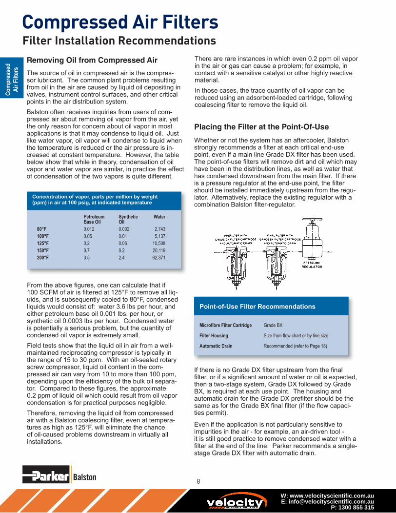
Removing Oil from Compressed Air
Placing the Filter at the Point-Of-Use
Filter Installation Recommendations
W: www.velocityscientific.com.auE: [email protected]
P: 1300 855 315

Compressed Air Filters
Using Filters With Air Dryers
Filter Installation RecommendationsMaintaining The Filters
W: www.velocityscientific.com.auE: [email protected]
P: 1300 855 315

10
Compressed Air Filters1/4” and 1/2” Line Size Filters
Model A914A
Model A914D,
A914P, A914
Model 2104 Series
Model 200X Series
W: www.velocityscientific.com.auE: [email protected]
P: 1300 855 315
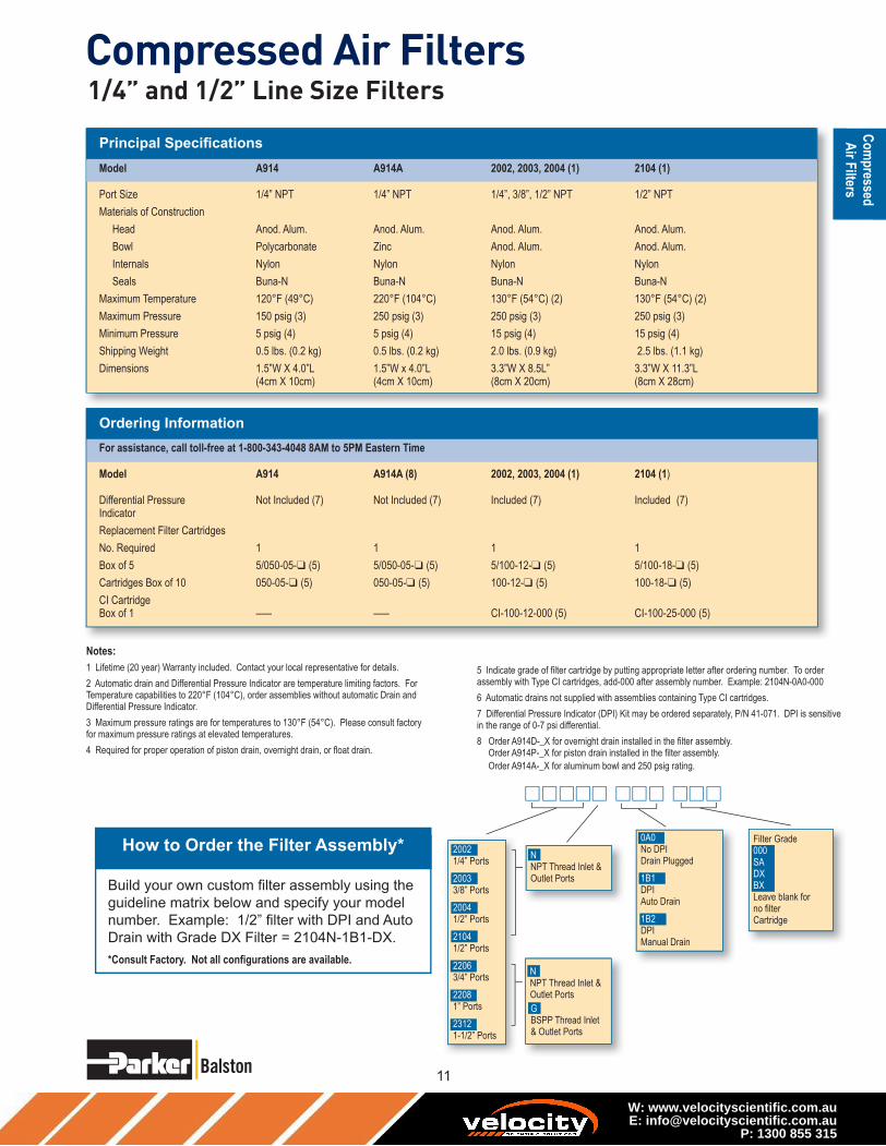
Compressed Air Filters
❑ ❑ ❑ ❑
❑ ❑ ❑ ❑
1/4” and 1/2” Line Size Filters
W: www.velocityscientific.com.auE: [email protected]
P: 1300 855 315

12
Compressed Air Filters3/4” to 2” Line Size Filters
Model 2206N
Model A15/80
Model 2312N
❑ ❑ ❑ ❑
❑ ❑ ❑ ❑
W: www.velocityscientific.com.auE: [email protected]
P: 1300 855 315
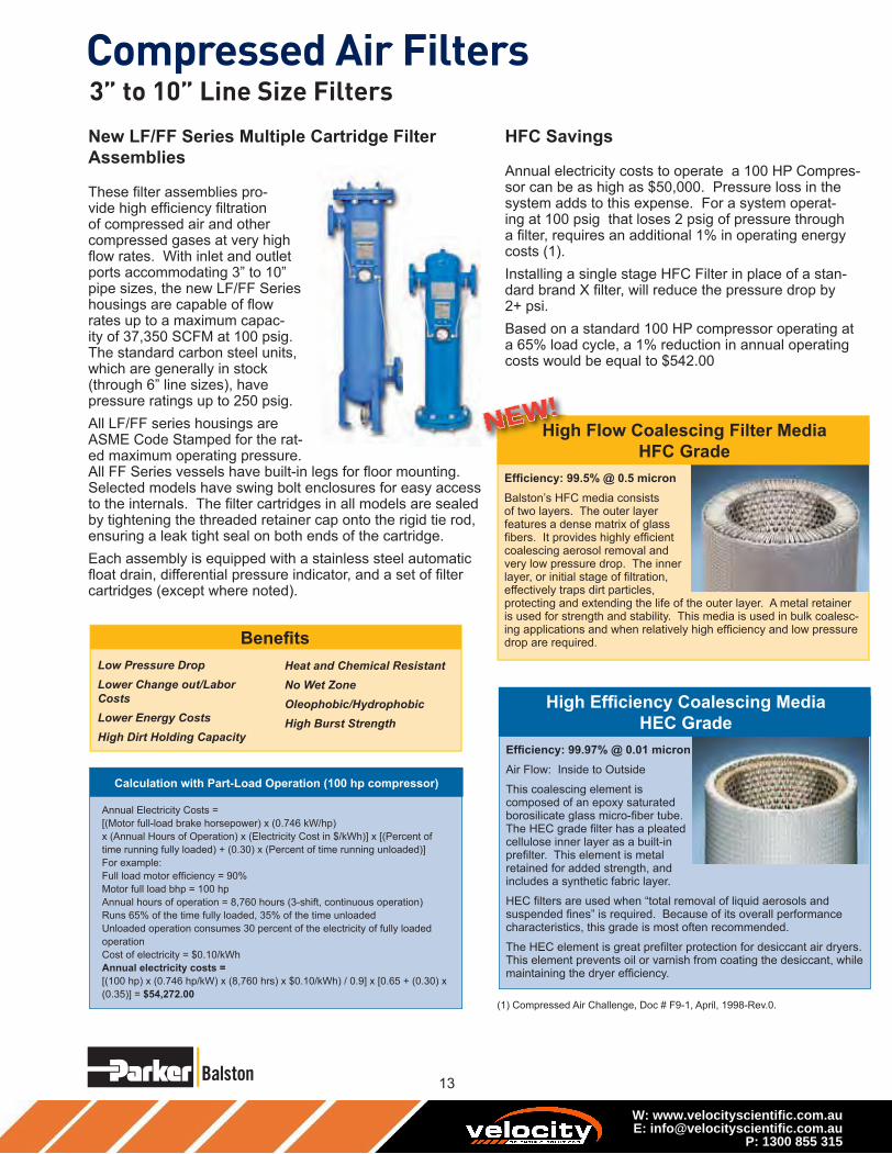
Compressed Air Filters3” to 10” Line Size Filters
W: www.velocityscientific.com.auE: [email protected]
P: 1300 855 315

14
Compressed Air Filters
�
�
�
�
W: www.velocityscientific.com.auE: [email protected]
P: 1300 855 315

Compressed Air FiltersDrawings, Dimensions & Specifi cations
1/2” NPT
Vent
1/4” NPT
Gauge
Ports
1/2” NPT
Drain
A
B
C
D
Refer to this drawing for:
ALN3
ALF3
ALF4
ALF6-0136
1/2” NPT
Vent
1/4” NPT
Gauge
Ports
1/2” NPT
Drain
A
B
C
D
Refer to this drawing for:ALF6-0328
1/2” NPT
Vent
1/4” NPT
Gauge
Port
1/4” NPT
Gauge
Port
1/2” NPT
Drain
1/2” NPT
DrainA
B
C
D
E
Refer to this drawing for:
AFN3
AFF3
AFF4
AFF6-0136
1/2” NPT
Vent
1/4” NPT
Gauge
Port
1/4” NPT
Gauge
Port
1/2” NPT
Drain
1/2” NPT
Drain
A
B
C
D
E
Refer to this drawing for:AFF6-0328
AFF8
AFF10
AFF12
AFF16
W: www.velocityscientific.com.auE: [email protected]
P: 1300 855 315

16
Compressed Air Filters
❑ ❑ ❑ ❑ ❑
❑ ❑ ❑ ❑ ❑
❑ ❑ ❑ ❑ ❑
W: www.velocityscientific.com.auE: [email protected]
P: 1300 855 315

Compressed Air Filters
www.balstonfilters.com
Product Features:
Balston Compressed Air Filters protect
your equipment and delicate instru-
ments from the dirt, water, and oil
usually found in compressed air and
other gases. These filters will remove
contaminants at a very high efficiency -
up to 99.99% for 0.01 micron particles
and droplets. Liquid releases from the
filter cartridge to an automatic drain as
rapidly as it enters the filter. This al-
lows the filter to continue removing liq-
uids for an unlimited time without loss
of efficiency or flow capacity. Select
1/4” to 1” line filters are constructed of
304 stainless steel and are designed to
hold up to the harshest environments.
Stainless Steel Compressed Air Filters for Harsh Environments
• All 304 stainless steel con-
struction, ideal standing up to
aggressive washdown chemi-
cals
• Remove 99.99% of 0.01 micron
particles of oil, water, and dirt
from compressed air and other
gases
• For Sterile Air Requirements:
• USDA accepted for use in
federally inspected meat and
poultry plants
• Low pressure drop
• Continuously trap and drain
liquids
• Remove trace oil vapor with
adsorbent cartridges
Balston Stainless Steel Compressed Air Filter Assemblies:
W: www.velocityscientific.com.auE: [email protected]
P: 1300 855 315

18
Compressed Air Filters
Balston Filter Cartridges
How to Select the Filter Cartridge
and Housing
How to Order the Filter Assembly
Stainless Steel Filters for Harsh Environments
W: www.velocityscientific.com.auE: [email protected]
P: 1300 855 315

Compressed Air Filters
Models 6102, 6002, 6904
Model 6004
Models 6006 and 6008
Model 6004Models 6102, 6002, 6904
Models 6006 and 6008
Stainless Steel Filters for Harsh Environments
W: www.velocityscientific.com.auE: [email protected]
P: 1300 855 315

20
Compressed Air Filters
Flow Rates
Sterile Air Filters Steam Sterilization Procedure
Stainless Steel Filters for Harsh Environments
W: www.velocityscientific.com.auE: [email protected]
P: 1300 855 315

Compressed Air Filters
Principal Specifi cations
Ordering Information For assistance, call toll-free at 1-800-343-4048 8AM to 5PM Eastern Time
Stainless Steel Filters for Harsh Environments
W: www.velocityscientific.com.auE: [email protected]
P: 1300 855 315

22
Compressed Air Filters
Models 9955-05-DX, 9955-11-DX,
9955-12-DX, AR-009-DX
Model 9955-11-DX
Model 9955-05-DX
Model 9955-12-DX
Model AR-009-DX
W: www.velocityscientific.com.auE: [email protected]
P: 1300 855 315

24
Compressed Air Filters
Filter-Regulator Combinations
AFR-940, AFR-940A
12E Series
00
Flow Characteristics12E31E13A
10 20 30 40 50
20
60
80
40
100
10 60 70
1/2 Inch Ports100 PSIG (6.9 bar)Primary Pressure
Sec
on
dar
y P
ress
ure
- P
SIG
Rated Flow - SCFM
Filter Regulators
W: www.velocityscientific.com.auE: [email protected]
P: 1300 855 315

Compressed Air Filters
How to Order
▼▼
▼
Filter Regulators
W: www.velocityscientific.com.auE: [email protected]
P: 1300 855 315

26
Compressed Air FiltersModel 17L Series
How to Select the Correct Lubricator
17L Series
00
10 20 30 40
7
1
2
3
4
5
6
50 60 70 80 90 100
Flow Characteristics17L22B 3/8 Inch Ports
Pre
ssu
re D
rop
- P
SIG
35 PSIG 90 PSIG 150 PSIGPrimary Pressure - PSIG
Flow - SCFM
00
10 20 30 40
7
1
2
3
4
5
6
50 60 70 80 90 100 110 120 130 140 150
Flow Characteristics17L32B 1/2 Inch Ports
&17L42B 3/4 Inch Ports
Pre
ssu
re D
rop
- P
SIG
35 PSIG 90 PSIG 150 PSIGPrimary Pressure - PSIG
Flow - SCFM
Mist Lubricators
W: www.velocityscientific.com.auE: [email protected]
P: 1300 855 315

Compressed Air FiltersMist Lubricators
W: www.velocityscientific.com.auE: [email protected]
P: 1300 855 315

28
Compressed Air Filters
1-800-343-4048
Basic
UnitSeries
Port Size (inches) Bowls
Capacity
Elements
(Micron)Page
1/8 1/4 3/8 1/2 3/4 1 1-1/4 1-1/2 2 2-1/2 3 Poly MetalMetal
SG5
F I L T E R S
FF10 X 316 Stainless Steel 4 oz. Standard 29
10F X X X X X 1 oz.Grade 6 Std.,
Grade 10 Opt.31
C O A L E S C E R S
FF501 X 316 Stainless Steel 1 oz. Grade 6 33
FF11 X 316 Stainless Steel 4 oz. Grade 6 35
Product Selection Chart
Basic
UnitSeries
Port Size (inches) SpringPage
1/8 1/4 3/8 1/2 3/4 1 1-1/2 125
R E G U L A T O R S
S T A N D A R D
FR364 X Standard 37
05R X X Standard 39
FR10 X Standard 41
07R X X X Standard 43
P3NR X X X Standard 45
*Sight gauge
Selection Chart Prep-Air® II Air Preparation Units
W: www.velocityscientific.com.auE: [email protected]
P: 1300 855 315

Compressed Air Filters
www.balstonfilters.com
Product Selection Chart
Basic
UnitSeries
Port Size Bowls
Capacity
Elements
(Micron)Spring Range
Page
1/8 1/4 3/8 1/2 3/4 1 1-1/2 Poly MetalMetal
SG5 125
F I L T E R / R E G U L A T O R S
14E X X X X N/A 1 oz. Standard Standard 47
FB548 X316 Stainless
Steel1 oz. Standard Standard 49
06E X X X X X X 4.4 oz. Standard Standard 51
FB11 X316 Stainless
Steel4 oz. Standard Standard 53
*Sight gauge
Selection Chart Prep-Air® II Air Preparation Units
W: www.velocityscientific.com.auE: [email protected]
P: 1300 855 315

30
Compressed Air Filters
1-800-343-4048
(Spitter Drain)
The diaphragm in this drain
pulses when there is a pres-
sure differential such as
a valve cycling or cylinder
stroking downstream. This
action flexes the diaphragm
and allows the filter to drain
the entrapped water.
The float internal to this drain
rises with increased liquid
level. When the float rises, it
opens a seat area allowing
the trapped liquids to drain
through the bottom.
A manual override can be
pushed in the bottom of the
drain to unseat the float if par-
ticulates create a block.
1/8" NPTAccepts1/8 I.D. Tubing
Automatic Pulse Drain Automatic Float Drain
Air Preparation Units - Drains
W: www.velocityscientific.com.auE: [email protected]
P: 1300 855 315

Compressed Air Filters
www.balstonfilters.com
AutomaticDrain
TwistDrain
D E
C
B Dia.Distance RequiredTo Remove All Bowls Regardless of Drain Option
F
A Dia.
Optional Sight GaugeA1
1/8”FemaleThread*
Port
Size
NPT without sight gauge NPT with sight gauge
Manual
Twist Drain
Automatic
Float Drain
Manual
Twist Drain
Automatic
Float Drain
1/2" FF10-04DGSS FF10-04DGRSS FF10-04WGSS FF10-04WGRSS
F10 Filter
Dimensions
A
2.38
(60)
A1
2.50
(64)
B
1.75
(44)
C
.56
(14)
D
5.00
(127)
E
5.56
(141)
F
2.12
(54)
inches
(mm)
SCFM = Standard cubic feet per minute at 90 PSIG inlet
and 5 PSIG pressure drop.
Features
• Stainless steel construction
handles
most corrosive environments.
• Meets NACE specifications
MR-01-75/ISO 15156.
• 1/8" female threaded drain.
• High Flow: 1/2" - 70 SCFM §
Air Preparation Units - FF10 Filter - Standard 1/2” NPT Ports
Ordering Information
FF10 - 04 W G SS
Material
SS Stainless Steel
Options
Blank Manual
Twist
Drain
R Automatic
Float
Drain
Element
G 5 Micron
Bowl
D Metal Bowl
without
Sight Gauge
W Metal Bowl
with
Sight Gauge
Port Size
04 1/2 Inch
Port Type
- NPT
W: www.velocityscientific.com.auE: [email protected]
P: 1300 855 315

32
Compressed Air Filters
1-800-343-4048
0
1
2
3
4
5
0 10 20 30 40 50 60 70 80
Pre
ssu
re D
rop
- P
SIG
0
0 5 10 15 20 25 30 35
Flow - SCFM
Flow - dm /s
Pre
ssu
re D
rop
- b
ar
3
n
.1
.2
.3
Flow CharacteristicsFF10-04DGSS1/2 Inch Ports
25 PSIG 50 PSIG 75 PSIG 100 PSIGPrimary Pressure - PSIG
1.7 bar 3.4 bar 5.2 bar 6.9 barPrimary Pressure - bar
FF10 Filter Kits & AccessoriesDrain Kit –
Automatic Float Drain ......................................................SA602MDSS
Manual Twist Drain–
Small (Old) ................................................................. SA600Y7-1SS
Large (New) .....................................................................SAP05481
Filter Element Kits –
Particulate (5 Micron) Element ..................................................... EK55G
Pipe Nipple – 1/2" 316 Stainless Steel .................................. 616A28-SS
SpecificationsBowl Capacity ......................................................................... 4.0 Ounces
Filter Rating ...............................................................................5 Micron
Sump Capacity .........................................................................1.7 Ounce
Port Threads ............................................................................... 1/2 Inch
Pressure & Temperature Ratings –
Manual Twist Drain (D-Bowl) ..................0 to 300 PSIG (0 to 20.7 bar)
0°F to 180°F (-18°C to 82°C)
Manual Twist Drain (W-Bowl) .................0 to 250 PSIG (0 to 17.2 bar)
0°F to 150°F (-18°C to 66°C)
Automatic Float Drain ..............................15 to 175 PSIG (1 to 12 bar)
40°F to 125°F (4°C to 52°C)
Note: Air must be dry enough to avoid ice formation at temperatures
below 32°F (2°C).
Weight .............................................................................. 1.9 lb. (0.85 kg)
Materials of ConstructionBody ..........................................................................316 Stainless Steel
Bowls ........................................................................316 Stainless Steel
Deflector ........................................................................................Acetal
Drain .........................................................................316 Stainless Steel
Element Holder .............................................................................Acetal
Filter Element .................................................................... Polyethylene
Seals ..................................................................................Fluorocarbon
Sight Gauge ................................................................................Isoplast
Air Preparation Units - FF10 Air Line FiltersTechnical Information
W: www.velocityscientific.com.auE: [email protected]
P: 1300 855 315

Compressed Air Filters
www.balstonfilters.com
Air Preparation Units - 10F Coalescing Filters - Miniature1/8”, 1/4” Basic 1/8” Body
A
B
DE
C
Distance RequiredTo Remove All BowlsRegardless OfDrain Option
F
Standard part numbers shown bold, with Grade 6 Elements (for
Grade 10 Elements, replace “E” with “H” in the 6th position). For
other models refer to ordering information below.‡ For polycarbonate bowl see Caution on page 2.
§ SCFM = Standard cubic feet per minute at 90 PSIG inlet and 5 PSIG
pressure drop.
Accepts
1/8" Tubing
Automatic Drain
Features
• Removes liquid aerosols and sub-micron particles.
• Liquids gravitate to the bottom of the element
and will not re-enter the airstream.
• Oil free air for critical applications, such as
air gauging and pneumatic instrumentation
and controls.
• Interchangeable twist and
automatic pulse drains.
• Grade 6 element,
99.97% DOP efficiency.
• High Flow: Grade 6 Element
1/8" – 17 SCFM §
1/4" – 20 SCFM §
Grade 10 Element
1/8" – 19 SCFM §
1/4" – 24 SCFM §
10F Coalescing
Filter Dimensions
A
1.69
(43)
B
1.56
(39,6)
C
0.39
(10)
D
3.82
(97)
D†
3.67
(93)
E
4.21
(107)
E†
4.06
(103)
F
1.60
(41)
Port
Size
NPT
Twist Drain Automatic Pulse Drain
Poly Bowl ‡
1/8" 10F01E* 10F05E*
1/4" 10F11E* 10F15E*
Metal Bowl without Sight Gauge
1/8" 10F03E* 10F07E*
1/4" 10F13E* 10F17E*
Inches (mm)
† With Automatic Pulse Drain.
Bowl Options
Polycarbonate Bowl
1 Twist Drain
5 Automatic Pulse Drain
Metal Bowl
3 Twist Drain
7 Automatic Pulse Drain
10F 1 1 E * —
Elements
E Grade 6
H Grade 10
Port Size
0 1/8 Inch
1 1/4 Inch
Ordering Information
Port Type
Blank NPT
1 BSPP
2 BSPT
Engineering
Level
* Will be Entered
at Factory
NOTE: BOLD OPTIONS ARE STANDARD.
Ordering Information
10F Coalescing Filter Dimen-
sionsA
1.69
(43)
B1.56
(39,6)
C0.39
(10)
Inches (mm)
† With Automatic Pulse Drain.
E†
4.06
(103)
F1.60
(41)
D3.82
(97)
D†
3.67
(93)
E4.21
(107)
W: www.velocityscientific.com.auE: [email protected]
P: 1300 855 315

34
Compressed Air Filters
1-800-343-4048
Air Preparation Units - 10F Coalescing FiltersTechnical Information
10F Coalescing Filter Kits & AccessoriesBowl Kits –
Poly Bowl – Automatic Pulse Drain .................................. PS408BP
Twist Drain .......................................................PS404P
Metal Bowl – Automatic Pulse Drain .................................. PS451BP
Twist Drain .................................................. PS447BP
Filter Element Kits – Grade 6 (Standard) ..................................PS446P
Grade 10 (Optional) PS456P
Mounting Bracket Kit PS417BP
SpecificationsAutomatic Pulse Drain Tube Barb ............................................ 1/8 Inch
Bowl Capacity ........................................................................... 1 Ounce
Operation –
Normal Operating Pressure Drop ..........................................2 PSIG
Maximum Recommended Pressure Drop ........................... 10 PSIG
(Element should be replaced)
Port Threads ................................................................... 1/8, 1/4 Inch
Pressure & Temperature Ratings –
Polycarbonate Bowl ...............................0 to 150 PSIG (0 to 10.3 bar)
32°F to 125°F (0°C to 52°C)
Metal Bowl .............................................0 to 250 PSIG (0 to 17.2 bar)
32°F to 175°F (0°C to 80°C)
Automatic Pulse Drain......................10 to 250 PSIG (0.7 to 17.2 bar)
at 125°F (52°C) or less
Weight ....................................................................... 0.41 lb. (0.18 kg)
Materials of ConstructionBody .................................................................................................Zinc
Bowls ......................................................... Transparent Polycarbonate
Metal (Zinc) Without Sight Gauge
Drains – Twist Drain –
Body & Stem ........................................................... Plastic
Seals ......................................................................... Nitrile
Automatic Pulse Drain –
Piston & Seals .......................................................... Nitrile
Stem, Seat, Adaptor & Washers ....................... Aluminum
Element Holder .......................................................................... Plastic
Filter Element –
Borosilicate & felt glass fibers 99.97% DOP efficiency
Largest Aerosol Particle Passed (Grade 6) .....................0.01 Micron
Largest Solid Particle Passed (Grade 6) .........................0.30 Micron
Seals ............................................................................................ Nitrile
Grade 6
0 5 10 15 20 25 30 35 40 45 50
35 PSIG 90 PSIG 150 PSIGPrimary Pressure - PSIG
2.4 bar 6.2 bar 10.3 barPrimary Pressure - bar
0 5 10 15 20
Flow - SCFM
Flow - dm /s3
n
Flow Characteristics10F11H*
1/4 Inch Ports0
1
2
3
4
5
6
7
8
10
9
Pre
ssu
re D
rop
- P
SIG
0
.1
Pre
ssu
re D
rop
- b
ar
.2
.3
.4
.5
.6
0 5 10 15 20 25 30 35 40 45
35 PSIG 90 PSIG 150 PSIGPrimary Pressure - PSIG
2.4 bar 6.2 bar 10.3 barPrimary Pressure - bar
0 5 10 15 20
Flow - SCFM
Flow - dm /s3
n
Flow Characteristics10F01E*
1/8 Inch Ports0
1
2
3
4
5
6
7
8
10
9
Pre
ssu
re D
rop
- P
SIG
0
.1
Pre
ssu
re D
rop
- b
ar
.2
.3
.4
.5
.6
0 5 10 15 20 25 30 35 40 45
35 PSIG 90 PSIG 150 PSIGPrimary Pressure - PSIG
2.4 bar 6.2 bar 10.3 barPrimary Pressure - bar
0 5 10 15 20
Flow - SCFM
Flow - dm /s3
n
Flow Characteristics10F01E*
1/8 Inch Ports0
1
2
3
4
5
6
7
8
10
9
Pre
ssu
re D
rop
- P
SIG
0
.1
Pre
ssu
re D
rop
- b
ar
.2
.3
.4
.5
.6
0 5 10 15 20 25 30 35 40 45
35 PSIG 90 PSIG 150 PSIGPrimary Pressure - PSIG
2.4 bar 6.2 bar 10.3 barPrimary Pressure - bar
0 5 10 15 20
Flow - SCFM
Flow - dm /s3
n
Flow Characteristics10F01H*
1/8 Inch Ports0
1
2
3
4
5
6
7
8
10
9
Pre
ssu
re D
rop
- P
SIG
0
.1
Pre
ssu
re D
rop
- b
ar
.2
.3
.4
.5
.6
Grade 10
W: www.velocityscientific.com.auE: [email protected]
P: 1300 855 315

Compressed Air Filters
www.balstonfilters.com
Ordering Information
D
F
C
E
A Dia.
DistanceRequiredTo RemoveAll Bowls
1/8”FemaleThread*
Port
Size
NPT
Manual Twist Drain
1/4" FF501-02DHSS
F501 Coalescing Filter
Dimensions
A
1.56
(40)
C
0.31
(8)
D
3.69
(94)
E
4.00
(102)
F
1.58
(40)
inches
(mm)
Standard part numbers shown bold. For other models refer to ordering
information below.
SCFM = Standard cubic feet per minute at 90 PSIG inlet and 5 PSIG pressure
drop.
Features• Stainless steel construction handles
most corrosive environments.
• Meets NACE specifications
MR-01-75/ISO 15156.
• 1/8" female threaded drain*.
• High Flow: 1/4" - 16 SCFM §
Port Type
- NPT
Port Size
02 1/4 Inch
Bowl
D Metal Bowl
without
Sight Gauge
Element
H .3 Micron
Material
SS Stainless Steel
FF501 - 02 D H SS
Air Preparation Units FF501 Coalescing Filter - Miniature 1/4” Ports
W: www.velocityscientific.com.auE: [email protected]
P: 1300 855 315

36
Compressed Air Filters
1-800-343-4048
0
1
2
3
6
7
8
9
10
4
5
0 5 10 15 20 25 30 35
Pre
ssu
re D
rop
- P
SIG
0
0 5 10 15
Flow - SCFM
Flow - dm /s
Pre
ssu
re D
rop
- b
ar
3
n
.2
.4
.6
Flow CharacteristicsF501-02DHSS1/4 Inch Ports
35 PSIG 90 PSIG 150 PSIGPrimary Pressure - PSIG
2.4 bar 6.2 bar 10.3 barPrimary Pressure - bar
FF501 Filter Kits & AccessoriesFilter Element Kits –
0.3 Micron ...................................................................................EKF31
Manual Twist Drain –
Small (Old) ..................................................................... SA600Y7-1SS
Large (New) .........................................................................SAP05481
Pipe Nipple –
1/4" 316 Stainless Steel ......................................................616Y28-SS
SpecificationsBowl Capacity ......................................................................... 1.0 Ounces
Filter Rating ............................................................................ 0.3 Micron
Port Threads ............................................................................... 1/4 Inch
Pressure & Temperature Ratings –
Manual Twist Drain......................................0 to 300 PSIG (0 to 20.7 bar)
0°F to 180°F (-18°C to 82°C)
Note: Air must be dry enough to avoid ice formation at temperatures
below 32°F (2°C)
Sump Capacity .........................................................................0.4 Ounce
Weight ............................................................................. 0.6 lb. (0.27 kg)
Materials of ConstructionBody ..........................................................................316 Stainless Steel
Bowls ........................................................................316 Stainless Steel
Drain ........................................................................................................
316 Stainless Steel
Element Holder .............................................................................Acetal
Filter Element ............................................................Borosilicate Fiber
Seals ..................................................................................Fluorocarbon
Air Preparation Units - F501 Series Technical Information
W: www.velocityscientific.com.auE: [email protected]
P: 1300 855 315
Compressed Air Filters
www.balstonfilters.com
Ordering Information
D E
C
B Dia.Distance RequiredTo Remove All Bowls Regardless of Drain Option
F
A Dia.
Optional Sight GaugeA1
1/8”FemaleThread*
F11 Coalescing Filter
Dimensions
A
2.38
(60)
A1
2.50
(64)
B
1.75
(44 )
C
0.56
(14)
D
5.00
(127)
E
5.56
(141)
F
2.12
(54)
inches
(mm)
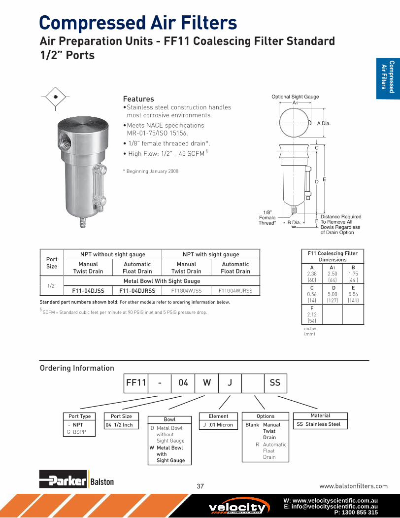
Features• Stainless steel construction handles
most corrosive environments.
• Meets NACE specifications
MR-01-75/ISO 15156.
• 1/8" female threaded drain*.
• High Flow: 1/2" - 45 SCFM §
* Beginning January 2008
Material
SS Stainless Steel
Element
J .01 Micron
Port Size
04 1/2 Inch
Port Type
- NPT
G BSPP
FF11 - 04 W J SS
Port
Size
NPT without sight gauge NPT with sight gauge
Manual
Twist Drain
Automatic
Float Drain
Manual
Twist Drain
Automatic
Float Drain
1/2"Metal Bowl With Sight Gauge
F11-04DJSS F11-04DJRSS F11G04WJSS F11G04WJRSS
Options
Blank Manual
Twist
Drain
R Automatic
Float
Drain
Bowl
D Metal Bowl
without
Sight Gauge
W Metal Bowl
with
Sight Gauge
Standard part numbers shown bold. For other models refer to ordering information below.
§ SCFM = Standard cubic feet per minute at 90 PSIG inlet and 5 PSIG pressure drop.
Air Preparation Units - FF11 Coalescing Filter Standard 1/2” Ports
W: www.velocityscientific.com.auE: [email protected]
P: 1300 855 315

38
Compressed Air Filters
1-800-343-4048
0
1
2
3
6
7
8
9
10
4
5
0 10 20 30 40 50 60 70 80
Pre
ssu
re D
rop
- P
SIG
0
0 5 10 15 20 25 30 35
Flow - SCFM
Flow - dm /s
Pre
ssu
re D
rop
- b
ar
3
n
.2
.4
.6
Flow CharacteristicsFF11-04DJSS1/2 Inch Ports
35 PSIG 90 PSIG 150 PSIGPrimary Pressure - PSIG
2.4 bar 6.2 bar 10.3 barPrimary Pressure - bar
F11 Filter Kits & AccessoriesDrain Kit –
Automatic Float Drain ......................................................SA602MDSS
Manual Twist Drain–
Small (Old) ................................................................. SA600Y7-1SS
Large (New) .....................................................................SAP05481
Filter Element Kits –
0.3 Micron ...................................................................................EKF71
Pipe Nipple –
1/2" 316 Stainless Steel ..................................................... 616A28-SS
SpecificationsBowl Capacity ......................................................................... 4.0 Ounces
Filter Rating .......................................................................... 0.01 Micron
Sump Capacity .........................................................................1.7 Ounce
Port Threads ............................................................................... 1/2 Inch
Pressure & Temperature Ratings –
Manual Twist Drain ................................0 to 300 PSIG (0 to 20.7 bar)
0°F to 180°F (-18°C to 82°C)
Manual Twist Drain (W) ...........................0 to 250 PSIG (0 to 17.2 bar)
0°F to 150°F (-18°C to 66°C)
Automatic Float Drain ...............................0 to 175 PSIG (0 to 12 bar)
40°F to 125°F (4°C to 52°C)
Note: Air must be dry enough to avoid ice formation at temperatures
below 32°F (2°C).
Weight .............................................................................. 1.9 lb. (0.85 kg)
Materials of ConstructionBody ..........................................................................316 Stainless Steel
Bowls ........................................................................316 Stainless Steel
Drain .........................................................................316 Stainless Steel
Element Holder .............................................................................Acetal
Filter Element ............................................................Borosilicate Fiber
Seals ..................................................................................Fluorocarbon
Sight Gauge ................................................................................ Isoplast
1Tested per ISO 12500-1 at 40 ppm inlet. 2Add dry + wet for total pressure drop.
GradeDesig-nation
Coalescing Efficiency0.3 to 0.6 Micron
Particles
MaximumOil
Carryover1
PPM w/w
Micron Rating
Pressure Drop (PSID)
@ Rated Flow2
Flow: SCFM
@3 PSID Operating Pressure 100 PSIG
MediaDry
MediaWet With
10-20 wt. oil
6 99.97% 0.008 0.01 1.0 2-3 ??
10 95% 0.85 1.0 0.5 0.5 ??
FF11 Media Specifications
Air Preparation Units - FF11 Series Technical Information
W: www.velocityscientific.com.auE: [email protected]
P: 1300 855 315

Compressed Air Filters
www.balstonfilters.com
Ordering Information
Features• Stainless steel construction handles
most corrosive environments.
• Large diaphragm to valve area ratio
for precise regulation and high flow
capacity.
• Meets NACE specifications
MR-01-75/ISO 15156.
• High Flow: 1/4" – 12 SCFM§
C1
E1
D
ADia.
Material
SS Stainless Steel
Pressure Range
C 0-125 PSIG
(0-8.5 bar)
Port Size
02 1/4 Inch
§ SCFM = Standard cubic feet per minute at 100 PSIG inlet, 75 PSIG no flow
secondary setting and 15 PSIG pressure drop.
SeriesAdjustment
TypePortSize NPT
FR364 Knob 1/4" R364-02CSS
R364 Regulator
Dimensions
A
1.56
(40)
C1
2.56
(65)
D
0.50
(13)
E1
3.06
(78)
inches (mm)
NOTE: 1.25 Dia.
(32mm) hole
required for panel
mounting.
FR364 - 02 C SS
Port Type
- NPT
Series
R364 Standard Knob
R364
! WARNING
Product rupture can cause serious injury.Do not connect regulator to bottled gas.
Do not exceed maximum primary pressure rating.
R364
Air Preparation Units - FR364 Regulator -Miniature 1/4” Ports
W: www.velocityscientific.com.auE: [email protected]
P: 1300 855 315
40
Compressed Air Filters
1-800-343-4048
0
20
30
50
10
40
60
70
90
80
100
0 2 4 6 8 10 12 14 16 18 20
Pre
ssu
re D
rop
- P
SIG
0
0 .1 .3 .5 .7 .9 1.1 1.3
Flow - SCFM
Flow - dm /s
Pre
ssu
re D
rop
- b
ar
3
n
1
2
3
4
5
6
Flow Characteristics
1/4 Inch Ports100 PSIG (6.9 bar Primary Pressure
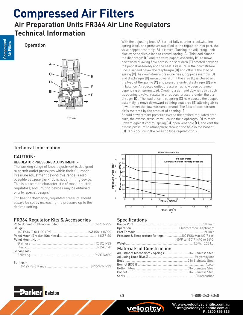
Operation
SpecificationsGauge Port .................................................................................. 1/4 Inch
Operation ....................................................... Fluorocarbon Diaphragm
Port Threads ............................................................................... 1/4 Inch
Pressure & Temperature Ratings – ................. 300 PSIG Max (20.7 bar)
40°F to 150°F (4°C to 66°C)
Weight .............................................................................. 0.5 lb. (0.23 kg)
Materials of ConstructionAdjustment Mechanism / Springs ...........................316 Stainless Steel
Adjusting Knob (R364) ...................................................... Polypropylene
Body ..........................................................................316 Stainless Steel
Bonnet (R364) ................................................................................Acetal
Bottom Plug ..............................................................316 Stainless Steel
Poppet .......................................................................316 Stainless Steel
Seals ..................................................................................Fluorocarbon
FR364 Regulator Kits & AccessoriesR364 Bonnet Kit (Knob Included) ........................................CKR364YSS
Gauge –
160 PSIG (0 to 1100 kPa) ........................................... K4515N14160SS
Panel Mount Bracket (Stainless) ............................................161X57-SS
Panel Mount Nut –
Stainless ............................................................................R05X51-SS
Plastic ...................................................................................R05X51-P
Service Kit –
Relieving ............................................................................RKR364YSS
Springs –
0-125 PSIG Range .................................................... SPR-377-1-SS
Technical Information
With the adjusting knob (A) turned fully counter-clockwise (no
spring load), and pressure supplied to the regulator inlet port, the
valve poppet assembly (B) is closed. Turning the adjusting knob
clockwise applies a load to control spring (C). This load causes
the diaphragm (D) and the valve poppet assembly (B) to move
downward allowing flow across the seat area (E) created between
the poppet assembly and the seat. Pressure in the downstream
line is sensed below the diaphragm (D) and offsets the load of
spring (C). As downstream pressure rises, poppet assembly (B)
and diaphragm (D) move upward until the area (E) is closed and
the load of the spring (C) and pressure under diaphragm (D) are
in balance. A reduced outlet pressure has now been obtained,
depending on spring load. Creating a demand downstream, such
as opening a valve, results in a reduced pressure under the dia-
phragm (D). The load of control spring (C) now causes the poppet
assembly to move downward opening seat area (E) allowing air to
flow to meet the downstream demand. The flow of downstream
air is metered by the amount of opening (E).
Should downstream pressure exceed the desired regulated pres-
sure, the excess pressure will cause the diaphragm (D) to move
upward against control spring (C), open vent hole (F), and vent the
excess pressure to atmosphere through the hole in the bonnet
(H). (This occurs in the relieving type regulator only.)
H
F
E
A
D
C
B
FR364
CAUTION:REGULATOR PRESSURE ADJUSTMENT –
The working range of knob adjustment is designed
to permit outlet pressures within their full range.
Pressure adjustment beyond this range is also
possible because the knob is not a limiting device.
This is a common characteristic of most industrial
regulators, and limiting devices may be obtained
only by special design.
For best performance, regulated pressure should
always be set by increasing the pressure up to the
desired setting.
Air Preparation Units FR364 Air Line RegulatorsTechnical Information
W: www.velocityscientific.com.auE: [email protected]
P: 1300 855 315

Compressed Air Filters
www.balstonfilters.com
Features• Secondary aspiration plus balanced poppet provides
quick response and accurate pressure regulation.
• Rolling diaphragm for extended life.
• Removable non-rising knob for panel mounting
and tamper resistance.
• Easily serviced.
• Reverse Flow.
• High Flow: 1/4" – 30 SCFM§
3/8" – 40 SCFM§
NOTE: 1.53 Dia. (39mm) hole required for panel mounting.
§ SCFM = Standard cubic feet per minute at 100 PSIG inlet,
90 PSIG no flow secondary setting and 10 PSIG pressure drop.
A
B
PU
SH TO LOCK
C
D
E
1/4" NPTGauge Ports
(2)
Options
Blank No Options
Preset / Pressure
Limited
Blank None
Port Type
Blank NPT
Port Size
1 1/4 Inch
2 3/8 Inch
Pressure Range
Without Gauge
13 125 PSIG
With Gauge**
18 125 PSIG
05R 1 13 A * — — ---
Port Size NPT
Without Gauge
1/4" 05R113A*
3/8" 05R213A*
With 160 PSI Gauge
1/4" 05R118A*
3/8" 05R218A*
05R Regulator
DimensionsA
2.00
(51)
B
2.06
(52)
C
3.16
(80)
D
1.28
(32)
E
4.44
(113)
Inches (mm)
Ordering Information
** Includes 1-1/2"
Dial Face Gauge
Engineering
Level
* Will be
Entered at
Factory† Inlet Pressure is 100 PSIG.
For other pressures,
contact factory.
Relief
A Relieving
* 1/4 & 3/8 inch
meet ISO 1179-1
Standard.
Air Preparation Units - 05R Regulators - Economy1/4”, 3/8” NPT - Basic 1/4” Body
W: www.velocityscientific.com.auE: [email protected]
P: 1300 855 315

42
Compressed Air Filters
1-800-343-4048
SpecificationsGauge Ports (2) ...........................................................................1/4 Inch
Port Threads ........................................................................1/4, 3/8 Inch
Primary Pressure Rating –
Maximum Primary Pressure .......................250 PSIG (17.2 bar) Max.
For Secondary Pressure Ranges see above charts.
Temperature Rating ....................................32°F to 175°F (0°C to 80°C)
Low Temperature .................................-4°F to 125°F (-20°C to 52°C)
Weight ............................................................................ 1.1 lb. (0.49 kg)
Materials of ConstructionAdjusting Stem .............................................................................. Brass
Bonnet ...........................................................................................Plastic
Body ................................................................................................... Zinc
Collar, Knob ...................................................................................Plastic
Diaphragm .....................................................................................Nitrile
Poppet & Cap ................................................................................Plastic
Seals ...............................................................................................Nitrile
Springs – Poppet & Control .............................................................Steel
05R Regulator Kits & AccessoriesBonnet Assembly Kit .................................................................. PS915P
Control Knob ................................................................................P04420
Gauges – 1-1/2" Dial Face ????
30 PSIG (0 to 2.1 bar) ....................................... K4515N14030
60 PSIG (0 to 4.1 bar) ....................................... K4515N14060
160 PSIG (0 to 11.0 bar) ................................... K4515N14160
300 PSIG (0 to 20.0 bar) ................................... K4515N14300
2" Dial Face
60 PSIG (0 to 4.1 bar) ..................................... K4520N14060
160 PSIG (0 to 11.0 bar) ..................................K4520N14160
Mounting Bracket Kit ................................................................PS963P
Panel Mount Nut – Metal ........................................................... PS964P
Springs – 1-30 PSIG Range ........................................................P04427
1-60 PSIG Range ........................................................P04426
2-125 PSIG Range ......................................................P04425
2-200 PSIG ..................................................................P02934
Service Kit – Relieving ............................................................ PS908P
0
15
30
45
60
75
90
105
120
10 0 10 20 30 40 50 60 70 80
Relief and Flow Characteristics05R113A*
05 5 10 15 20 25 30 35
Flow (SCFM)
Flow - dm /s3
n
0
1 Sec
on
dar
y P
ress
ure
- P
SIG
Sec
on
dar
y P
ress
ure
- b
ar
2
3
4
5
6
7
8
1/4 Inch PortsPrimary Pressure 100 PSIG (6.9 bar)
0
15
30
45
60
75
90
105
120
10 0 10 20 30 40 50 60 70 80
Relief and Flow Characteristics05R213A*
05 5 10 15 20 25 30 35
Flow (SCFM)
Flow - dm /s3
n
0
1 Sec
on
dar
y P
ress
ure
- P
SIG
Sec
on
dar
y P
ress
ure
- b
ar
2
3
4
5
6
7
8
3/8 Inch PortsPrimary Pressure 100 PSIG (6.9 bar)
! WARNING
Product rupture can cause serious injury.Do not connect regulator to bottled gas.
Do not exceed maximum primary pressure rating.
CAUTION:REGULATOR PRESSURE ADJUSTMENT – The working
range of knob adjustment is designed to permit outlet
pressures within their full range. Pressure adjustment
beyond this range is also possible because the knob is not
a limiting device. This is a common characteristic of most
industrial regulators, and limiting devices may be obtained
only by special design.
For best performance, regulated pressure should always be
set by increasing the pressure up to the desired setting.
Air Preparation Units 05R Air Line Regulators Technical Information
W: www.velocityscientific.com.auE: [email protected]
P: 1300 855 315

Compressed Air Filters
www.balstonfilters.com
Ordering Information
A
B
C
E
D
Features• Stainless steel construction handles
most corrosive environments.
• Large diaphragm to valve area ratio for precise regulation and high flow capacity.
• Meets NACE specifications MR-01-75/ISO 15156.
• Low temperature version available.
• High Flow: 1/2" – 80 SCFM§
PortSize NPT
1/2" FR10-04CSS
Material
SS Stainless Steel
Pressure Range
C 0-125 PSIG
(0-8.5 bar)
Port Size
04 1/2 Inch
FR10 - 04 C SS
Port Type
- NPT
§ SCFM = Standard cubic feet per minute at 100 PSIG inlet, 75 PSIG no flow
secondary setting and 15 PSIG pressure drop.
R10, R11 Regulator
Dimensions
A
2.34
(60)
B
2.43
(62)
C
3.59
(91)
D
1.38
(35)
E
4.97
(126)
inches (mm)
NOTE: 1.75 Dia. (44mm) hole
required for panel mounting.
Series
R10 Standard Knob
R10
! WARNING
Product rupture can cause serious injury.Do not connect regulator to bottled gas.
Do not exceed maximum primary pressure rating.
R10
Air Preparation Units - FR10 Regulator - Standard 1/2” Ports
W: www.velocityscientific.com.auE: [email protected]
P: 1300 855 315

44
Compressed Air Filters
1-800-343-4048
0
20
30
50
10
40
60
70
90
80
100
0 10 20 30 40 50 60 70 80 90 100
Pre
ssu
re D
rop
- P
SIG
0
0 5 10 15 20 25 30 35 40 45
Flow - SCFM
Flow - dm /s
Pre
ssu
re D
rop
- b
ar
3
n
1
2
3
4
5
6
Flow Characteristics
1/2 Inch Ports100 PSIG (6.9 bar Primary Pressure
SpecificationsGauge Port .................................................................................. 1/4 Inch
Operation ....................................................... Fluorocarbon Diaphragm
Port Threads ............................................................................... 1/2 Inch
Pressure & Temperature Ratings – ................. 300 PSIG Max (20.7 bar)
0°F to 150°F (-18°C to 66°C)
Note: Air must be dry enough to avoid ice formation at temperatures
below 32°F (2°C).
Weight ............................................................................ 1.79 lb. (0.81 kg)
Materials of ConstructionAdjustment Mechanism / Springs ...........................316 Stainless Steel
Body ..........................................................................316 Stainless Steel
Bonnet / Knob (R10) ......................................................................Acetal
Bottom Plug ..............................................................316 Stainless Steel
Poppet .......................................................................316 Stainless Steel
Seals ..................................................................................Fluorocarbon
FR10 Regulator Kits & AccessoriesR10 Bonnet Kit (Knob Included) ............................................CKR10YSS
Gauge –
160 PSIG (0 to 1100 kPa), 2" Face ............................. K4520N14160SS
Panel Mount Bracket (Stainless) ............................................161X57-SS
Panel Mount Nut –
Stainless ............................................................................R10X51-SS
Plastic ...................................................................................R10X51-P
Service Kit –
Relieving ..............................................................................RKR10YSS
Springs –
0-125 PSIG Range ........................................................ SPR-389-1-SS
Operation
D
A
C
B
H
F
E
Technical Information
With the adjusting knob (A) turned fully counter-clockwise (no
spring load), and pressure supplied to the regulator inlet port, the
valve poppet assembly (B) is closed. Turning the adjusting knob
clockwise applies a load to control spring (C). This load causes
the diaphragm (D) and the valve poppet assembly (B) to move
downward allowing flow across the seat area (E) created between
the poppet assembly and the seat. Pressure in the downstream
line is sensed below the diaphragm (D) and offsets the load of
spring (C). As downstream pressure rises, poppet assembly (B)
and diaphragm (D) move upward until the area (E) is closed and
the load of the spring (C) and pressure under diaphragm (D) are
in balance. A reduced outlet pressure has now been obtained,
depending on spring load. Creating a demand downstream,
such as opening a valve, results in a reduced pressure under
the diaphragm (D). The load of control spring (C) now causes
the poppet assembly to move downward opening seat area (E)
allowing air to flow to meet the downstream demand. The flow of
downstream air is metered by the amount of opening (E).
Should downstream pressure exceed the desired regulated
pressure, the excess pressure will cause the diaphragm (D) to
move upward against control spring (C), open vent hole (F), and
vent the excess pressure to atmosphere through the hole in the
bonnet (H). (This occurs in the relieving type regulator only.)
CAUTION:REGULATOR PRESSURE ADJUSTMENT –
The working range of knob adjustment is designed
to permit outlet pressures within their full range.
Pressure adjustment beyond this range is also
possible because the knob is not a limiting device.
This is a common characteristic of most industrial
regulators, and limiting devices may be obtained
only by special design.
For best performance, regulated pressure should
always be set by increasing the pressure up to the
desired setting.
Air Preparation Units FR10 Air Line Regulators Technical Information
W: www.velocityscientific.com.auE: [email protected]
P: 1300 855 315

Compressed Air Filters
www.balstonfilters.com
C
E
D
B
AP
USH TO LOC
K
1/4" NPTGauge Ports
(2)
Features• Secondary aspiration plus balanced poppet provides
quick response and accurate pressure regulation.
• Rolling diaphragm for extended life.
• Two high flow 1/4" gauge ports can be used as addi-
tional outlets.
• Easily serviced.
• Removable non-rising knob for panel mounting
and tamper resistance.
• High Flow: 3/8" – 70 SCFM§
1/2" – 90 SCFM§
3/4" – 90 SCFM§
NOTE: 2.00 Dia. (51mm) hole required for panel mounting.
§ SCFM = Standard cubic feet per minute at 100 PSIG inlet,
90 PSIG no flow secondary setting and 10 PSIG pressure drop.
Options
Blank No Options
Preset / Pressure
Limited
Blank None
† Inlet Pressure is 100 PSIG.
For other pressures,
contact factory.
Port Type
Blank NPT
Port Size
2 3/8 Inch
3 1/2 Inch
4 3/4 Inch
Pressure Range
Without Gauge
13 125 PSIG
Relief
A Relieving
07R 3 13 A * — — ---
! WARNING
Product rupture can cause serious injury.Do not connect regulator to bottled gas.
Do not exceed maximum primary pressure rating.
Port Size NPT
Without Gauge
3/8" 07R213A*
1/2" 07R313A*
3/4" 07R413A*
Ordering Information
Engineering
Level
* Will be
Entered at
Factory
07R Regulator
DimensionsA
3.24
(82)
B
2.74
(70)
C
4.79
(122)
D
1.61
(41)
E
6.40
(163)
Inches (mm)
* 3/8 & 1/2 inch
meet ISO 1179-1
Standard.
Air Preparation Units - 07R Regulators - Standard 3/8”, 1/2”, 3/4” NPT - Basic 1/2” Body
W: www.velocityscientific.com.auE: [email protected]
P: 1300 855 315

46
Compressed Air Filters
1-800-343-4048
07R Regulator Kits & Accessories
Bonnet Assembly Kit .................................................................. PS715P
Control Knob ............................................................................. P04069B
Gauges – 60 PSIG (0 to 4.1 bar) ...................................... K4520N14060
160 PSIG (0 to 11.0 bar) .................................. K4520N14160
Mounting Bracket Kit (Includes Panel Mount Nut) .................... PS807P
Panel Mount Nut – Plastic ........................................................P04082
Metal ....................................................... P04079B
Service Kit – Relieving (Includes Poppet) ............................... PS808P
Springs – 2-125 PSIG Range ...............................................P04063
Tamperproof Kit ......................................................................... PS737P
SpecificationsGauge Ports (2) ...........................................................................1/4 Inch
(Can be used as additional High Flow 1/4 Inch Outlet Ports)
Port Threads .................................................................3/8, 1/2, 3/4 Inch
Primary Pressure Rating –
Maximum Primary Pressure .................................250 PSIG (17.2 bar)
Secondary Pressure Range –
Standard Pressure .................................... 2 to 125 PSIG (0 to 8.6 bar)
Temperature Rating ....................................32°F to 175°F (0°C to 80°C)
Weight 2.5 lb. (1.1 kg)
Materials of ConstructionAdjusting Stem ............................................................................... Steel
Body ................................................................................................... Zinc
Bonnet, Piston Stem, Valve Poppet & Cap ..................................Plastic
Collar, Knob ...................................................................................Plastic
Diaphragm .....................................................................................Nitrile
Seals ...............................................................................................Nitrile
Springs – Poppet ....................................................................Stainless
Control ...........................................................................Steel
00
Relief And Flow Characteristics07R213A*
10 30 50 70 900
20
60
80
40
100
1
2
3
4
5
6
10 110 130
0 5 45 555 15 25 35
Sec
on
dar
y P
ress
ure
- P
SIG
Sec
on
dar
y P
ress
ure
- b
ar
Rated Flow - SCFM
Flow - dm /s3
n
3/8 Inch Ports100 PSIG (6.9 bar) Primary Pressure
00
Relief And Flow Characteristics07R313A*
10 30 50 70 900
20
60
80
40
100
1
2
3
4
5
6
10 110 130
0 5 45 555 15 25 35
Sec
on
dar
y P
ress
ure
- P
SIG
Sec
on
dar
y P
ress
ure
- b
ar
Rated Flow - SCFM
Flow - dm /s3
n
1/2 Inch Ports100 PSIG (6.9 bar) Primary Pressure
00
Relief And Flow Characteristics07R413A*
10 30 50 70 900
20
60
80
40
100
1
2
3
4
5
6
10 110 130 150 170
0 5 45 55 65 755 15 25 35
Sec
on
dar
y P
ress
ure
- P
SIG
Sec
on
dar
y P
ress
ure
- b
ar
Rated Flow - SCFM
Flow - dm /s3
n
3/4 Inch Ports100 PSIG (6.9 bar) Primary Pressure
CAUTION:REGULATOR PRESSURE ADJUSTMENT –
The working range of knob adjustment is designed
to permit outlet pressures within their full range.
Pressure adjustment beyond this range is also
possible because the knob is not a limiting device.
This is a common characteristic of most industrial
regulators, and limiting devices may be obtained
only by special design.
For best performance, regulated pressure should
always be set by increasing the pressure up to the
desired setting.
Air Preparation Units 07R Air Line Regulators Technical Information
W: www.velocityscientific.com.auE: [email protected]
P: 1300 855 315

Compressed Air Filters
www.balstonfilters.com
Features• Port blocks (PB) available to provide 1-1/2"
port extension to 1" ported bodies.
• Self relieving feature plus balanced poppet
provides quick response and accurate pres-
sure regulation.
• Solid control piston for extended life.
• High Flow: 3/4" – 200 SCFM§
1" – 300 SCFM§
1½" – 300 SCFM§
B
CE
D
AA (PB)
PU
SH TO LOCK
1/4" NPTGauge Ports
(2)
P3N R A 9 8 B N N
Pressure Gauge
Without Gauge
N 125 PSI (0 to 8 bar)
Adjustment
N Non-Rising
Knob
Relief
B Relieving
Port Size
6 3/4" (w/o
Port Blocks)
8 1" (w/o
Port Blocks)
P 1-1/2" Port
Blocks (w/ 1"
Ported Body)
Port Type
9 NPT Female
Design
Level
NOTE: 2.00 Dia. (51mm) hole required for panel mounting.
§ SCFM = Standard cubic feet per minute at 100 PSIG inlet,
90 PSIG no flow secondary setting and 10 PSIG pressure drop. ! WARNING
Product rupture can cause serious injury.Do not connect regulator to bottled gas.
Do not exceed maximum primary pressure rating.
Port Size NPT
Without Gauge
3/4" P3NRA96BNN
1" P3NRA98BNN
1½ P3NRA9PBNN
Ordering Information
P3NR Regulator
DimensionsA
3.62
(92)
A(PB)
5.91
(150)
B
3.62
(92)
C
6.38
(162)
D
2.08
(53)
E
8.46
(215)
Inches (mm)
* 3/4 & 1 inch meet ISO
1179-1 Standard.
Air Preparation Units - P3NR Regulators - High Flow3/4”, 1”, 1 1/2” NPT - Basic 1” Body
W: www.velocityscientific.com.auE: [email protected]
P: 1300 855 315

48
Compressed Air Filters
1-800-343-4048
† 1" Port Body with 1½" Port Block.
P3NR Regulator Kits & AccessoriesControl Knob P3NKA00PN
Gauges – 60 PSIG (0 to 4.1 bar) ...................................... K4520N14060
160 PSIG (0 to 11.0 bar) .................................. K4520N14160
Mounting Bracket Kit* ....................................................... P3NKA00MW
Service Kit – Relieving ..................................................... P3NKA00RR
Springs – 2-125 PSIG Range ..................................................C10A1308
SpecificationsGauge Ports (2) ...........................................................................1/4 Inch
(Can be used as additional High Flow 1/4 Inch Outlet Ports)
Port Threads ................................................................ 3/4, 1, 1-1/2 Inch
Primary Pressure Rating –
Maximum Primary Pressure ................................250 PSIG (17.2 bar)
Secondary Pressure Range –
Standard Pressure .................................... 2 to 125 PSIG (0 to 8.6 bar)
Temperature Rating ....................................32°F to 175°F (0°C to 80°C)
0
15
30
45
60
75
120
105
90
0 200100-100 300 400 500 600
0 50-50 100 150 200 250
Flow - SCFM
Pre
ssu
re D
rop
- P
SIG
0
1
Pre
ssu
re D
rop
- b
ar
2
3
4
5
7
6
83/4 Inch Ports
Primary Pressure 100 PSIG (6.9 bar)
Relief And Flow CharacteristicsP3NR
Flow - dm /s3
n
0
15
30
45
60
75
120
105
90
0 200100-100 300 400 500 700600
Pre
ssu
re D
rop
- P
SIG
0
1
0 50-50 100 150 200 250 300
Flow - SCFM
Pre
ssu
re D
rop
- b
ar
2
3
4
5
7
6
8
1 Inch PortsPrimary Pressure 100 PSIG (6.9 bar)
Relief And Flow CharacteristicsP3NR
Flow - dm /s3
n
0
15
30
45
60
75
120
105
90
0 200100-100 300 400 500 700600
Pre
ssu
re D
rop
- P
SIG
0
1
0 50-50 100 150 200 250 300
Flow - SCFM
Pre
ssu
re D
rop
- b
ar
2
3
4
5
7
6
81-1/2 Inch Ports
Primary Pressure 100 PSIG (6.9 bar)
Relief And Flow CharacteristicsP3NR
Flow - dm /s3
n
CAUTION:REGULATOR PRESSURE ADJUSTMENT –
The working range of knob adjustment is designed
to permit outlet pressures within their full range.
Pressure adjustment beyond this range is also
possible because the knob is not a limiting device.
This is a common characteristic of most industrial
regulators, and limiting devices may be obtained
only by special design.
For best performance, regulated pressure should
always be set by increasing the pressure up to the
desired setting.
Weight – 3/4" .................................................................... 4.2 lb. (1.9 kg)
1" ....................................................................... 4.2 lb. (1.9 kg)
1½" † ................................................................. 5.3 lb. (2.4 kg)
Materials of ConstructionAdjusting Stem ................................................................................Steel
Body .........................................................................................Aluminum
Bonnet .....................................................................................Aluminum
Knob ..............................................................................................Plastic
Piston .............................................................................................Plastic
Poppet Assembly ........................................................................... Brass
Seals ...............................................................................................Nitrile
Springs – Poppet & Control ..........................................................Steel
Air Preparation Units - P3NR Air Line Regulators Technical Information
W: www.velocityscientific.com.auE: [email protected]
P: 1300 855 315

Compressed Air Filters
www.balstonfilters.com
➤
➤
➤
➤
➤
➤
14E 1 1 B 13 F * — — ---
Port Size
0 1/8 Inch
1 1/4 Inch
Bowl Options
Polycarbonate Bowl
1 Twist Drain
5 Automatic Drain
Metal Bowl
3 Twist Drain
7 Automatic Drain
Elements
B 5 Micron
Relief
F Relieving
Pressure Range
13 125 PSIG
Port Type
Blank NPT
† Inlet Pressure is 100 PSIG. For
other pressures, contact factory.
Preset / Pressure
Limited
Blank None
Options
Blank No Options
Features• Excellent water removal efficiency.
• Unbalanced poppet standard.
• Solid control piston for extended life.
• Space saving package offers both filter
and regulator features in one integral unit.
• Non-rising adjustment knob.
• Two full flow 1/8" gauge ports.
• High Flow: 1/8" – 16 SCFM§
1/4" – 18 SCFM§
‡ For polycarbonate bowl see Caution on page A2.
§ SCFM = Standard cubic feet per minute at 100 PSIG inlet,
90 PSIG no flow secondary setting and 10 PSIG pressure drop.
NOTE: 1.218 Dia. (31mm) hole required for panel mounting.
PortSize
NPT
Twist Drain Automatic Pulse Drain
Poly Bowl‡
1/8" 14E01B13F* 14E05B13F*
1/4" 14E11B13F* 14E15B13F*
Metal Bowl
1/8" 14E03B13F* 14E07B13F*
1/4" 14E13B13F* 14E17B13F*
Ordering
Information
A
B
D
E
C
Distance RequiredTo Remove All BowlsRegardless OfDrain Option
F
1/8" NPTGauge Ports
(2)
Accepts1/8" Tubing
Automatic Drain
14E Filter / Regu-
lator DimensionsA
1.62
(41)
B
1.58
(40)
C
2.42
(61)
D
3.79
(96)
D †
3.64
(92)
E
6.21
(158)
E †
6.06
(154)
F
1.60
(41)
Inches (mm)
† With Auto Drain
Engineering
Level
* Will be
Entered at
Factory
➤
➤
➤
➤
➤
➤
Air Preparation Units - 14E Filter/Regulator - Miniature 1/8”, 1/4” NPT - Basic 1/8” Body
W: www.velocityscientific.com.auE: [email protected]
P: 1300 855 315

50
Compressed Air Filters
1-800-343-4048
14E Filter / Regulator Kits & AccessoriesBowl Kits –
Poly Bowl – Automatic Drain ..............................................PS408BP
Twist Drain......................................................... PS404P
Metal Bowl – Automatic Drain ..............................................PS451BP
Twist Drain.......................................................PS447BP
Filter Element Kits – 5 Micron .................................................. PS403P
Gauges –???? 30 PSIG (0 to 2.1 bar) ....................K4515N18030
60 PSIG (0 to 4.1 bar) ....................K4515N18060
160 PSIG (0 to 11.0 bar) ................ K4515N18160
Mounting Bracket Kit (Includes Panel Mount Nut) .................PS417BP
Panel Mount Nut .........................................................................P78652
Poppet Kit – Unbalanced ......................................................PS424BP
Service Kit – Relieving ............................................................ PS423P
Springs – 2- 125 PSIG Range (Gold) ..........................................P01173
SpecificationsAutomatic Pulse Drain Tube Barb .............................................1/8 Inch
Bowl Capacity .............................................................................1 Ounce
Gauge Ports (2) (Can be used for Full Flow) ..............................1/8 Inch
Port Threads ........................................................................1/8, 1/4 Inch
Pressure & Temperature Ratings –
Polycarbonate Bowl
0 to 150 PSIG (0 to 10.3 bar), 32°F to 125°F (0°C to 52°C)
Metal Bowl
0 to 250 PSIG (0 to 17.2 bar), 32°F to 175°F (0°C to 80°C)
Secondary Pressure Ranges –
Standard Pressure .............................. 2 to 125 PSIG (0 to 8.6 bar)
Weight .............................................................................. 0.4 lb. (0.18 kg)
Materials of ConstructionAdjusting Nut ................................................................................. Brass
Adjusting Stem & Spring ................................................................Steel
Body ................................................................................................... Zinc
Bonnet, Knob, Seat, Piston, Holder & Deflector ........................Plastic
Bowls Available – Transparent ..................................... Polycarbonate
Metal (Without Sight Gauge) ........................... Zinc
Drains – Manual – Twist Type
Body & Stem .............................................................Plastic
Seals ...........................................................................Nitrile
Automatic – Pulse Type
Piston & Seals ...........................................................Nitrile
Stem, Seat, Adaptor & Washers ........................Aluminum
Filter Elements – 5 Micron (Standard) ........................................Plastic
Seals ............................................................................................Nitrile
00
20
60
80
40
100
1
2
3
4
5
6
0 4 8 12 16 20 24 28 32
0 2 4 6 8 10 12 14
Relief And Flow Characteristics14E01B13F*
Sec
on
dar
y P
ress
ure
- P
SIG
Sec
on
dar
y P
ress
ure
- b
ar
Rated Flow - SCFM
Flow - dm /s3
n
1/8 Inch Ports100 PSIG (6.9 bar) Primary Pressure
00
4 8 12 16 20 24 28 32
0
0
20
60
80
40
100
1
2
3
4
5
6
2 4 6 8 10 12 14
Relief And Flow Characteristics14E11B13F*
Sec
on
dar
y P
ress
ure
- P
SIG
Sec
on
dar
y P
ress
ure
- b
ar
Rated Flow - SCFM
Flow - dm /s3
n
1/4 Inch Ports100 PSIG (6.9 bar) Primary Pressure
! WARNING
Product rupture can cause serious injury.Do not connect regulator to bottled gas.
Do not exceed maximum primary pressure rating.
CAUTION:REGULATOR PRESSURE ADJUSTMENT – The working range
of knob adjustment is designed to permit outlet pressures
within their full range. Pressure adjustment beyond this range
is also possible because the knob is not a limiting device. This
is a common characteristic of most industrial regulators, and
limiting devices may be obtained only by special design.
For best performance, regulated pressure should always be set
by increasing the pressure up to the desired setting.
Air Preparation Units - Prep Air II, 14E Filter/Regulators Technical Information
W: www.velocityscientific.com.auE: [email protected]
P: 1300 855 315

Compressed Air Filters
www.balstonfilters.com
Reduced
Pressure
Range
C 0-125 PSIG
(0-8.5 bar)
Ordering Information
Features• Stainless Steel Construction
Handles Most Corrosive
Environments
• Large Diaphragm To Valve Area
Ratio For Precise Regulation
And High Flow Capacity
• 1/8" Female Threaded Drain*
• Meets NACE Specifications
MR-01-75/ISO 15156.
• High Flow: 1/4" – 12 SCFM§
* Beginning January 2008
D
C1
E1
A Dia.
DistanceRequiredTo RemoveAll Bowls
F
1/8”FemaleThread
PortSize NPT
1/4" FB548-02DGCSS
Port Type
- NPT
Port Size
02 1/4 Inch
Bowl
D Metal Bowl
without
Sight Gauge
Element
G 5 Micron
Options
Blank Relieving
Material
SS Stainless Steel
FB548 - 02 D G C SS
§ SCFM = Standard cubic feet per minute at 100 PSIG inlet, 75 PSIG no flow
secondary setting and 15 PSIG pressure drop.
FB548 Piggyback
Dimensions
A
1.56
(40)
C1
2.17
(55)
D
3.63
(92)
E1
3.06
(78)
F
1.58
(40)
inches (mm)
NOTE: 1.25 Dia. (32mm) hole
required for panel mounting.
B548
Series
B548 Standard
Knob
➤
➤
➤
➤
➤
➤
! WARNING
Product rupture can cause serious injury.Do not connect regulator to bottled gas.
Do not exceed maximum primary pressure rating.
Air Preparation Units - FB548 Filter/Regulator - Miniature 1/4” Ports
W: www.velocityscientific.com.auE: [email protected]
P: 1300 855 315
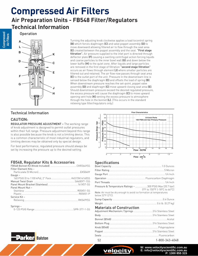
52
Compressed Air Filters
1-800-343-4048
0
20
30
50
10
40
60
70
90
80
100
0 2 4 6 8 10 12 14 16 18 20
Pre
ssu
re D
rop
- P
SIG
0
0 .1 .3 .5 .7 .9 1.1 1.3
Flow - SCFM
Flow - dm /s
Pre
ssu
re D
rop
- b
ar
3
n
1
2
3
4
5
6
Flow Characteristics
1/4 Inch Ports100 PSIG (6.9 bar Primary Pressure
Operation
SpecificationsBowl Capacity ......................................................................... 1.0 Ounces
Filter Rating ...............................................................................5 Micron
Gauge Port .................................................................................. 1/4 Inch
Operation ....................................................... Fluorocarbon Diaphragm
Port Threads ............................................................................... 1/4 Inch
Pressure & Temperature Ratings – ................. 300 PSIG Max (20.7 bar)
0°F to 150°F (-18°C to 66°C) Note: Air must be dry enough to avoid ice formation at temperatures
below 32°F (2°C).
Sump Capacity .........................................................................0.4 Ounce
Weight .............................................................................. 0.6 lb. (0.27 kg)
Materials of ConstructionAdjustment Mechanism / Springs ...........................316 Stainless Steel
Body ..........................................................................316 Stainless Steel
Bonnet (B548) ................................................................................Acetal
Bottom Plug ..............................................................316 Stainless Steel
Knob (B548) ...................................................................... Polypropylene
Poppet .......................................................................316 Stainless Steel
Seals ..................................................................................Fluorocarbon
FB548, Regulator Kits & AccessoriesFB548 Bonnet Kit (Knob Included) ......................................CKR364YSS
Filter Element Kits –
Particulate (5 Micron).............................................................EK504VY
Gauge –
160 PSIG (0 to 1100 kPa), 2" Face ............................. K4515N14160SS
Manual Twist Drain ........................................................... SA600Y7-1SS
Panel Mount Bracket (Stainless) ............................................161X57-SS
Panel Mount Nut –
Stainless ............................................................................R05X51-SS
Plastic ...................................................................................R05X51-P
Service Kit –
Relieving .............................................................................. RK549YSS
Springs –
0-125 PSIG Range ........................................................ SPR-377-1-SS
Technical Information
L
F
G
D
A
BK
C
E
J
H
Turning the adjusting knob clockwise applies a load tocontrol spring
(B) which forces diaphragm (C) and valve poppet assembly (D) to
move downward allowing filtered air to flow through the seat area
(E) created between the poppet assembly and the seat. “First stage
filtration”. Air pressure supplied to the inlet port is directed through
deflector plate (F) causing a swirling centrifugal action forcing liquids
and coarse particles to the inner bowl wall (G) and down below the
lower baffle (H) to the quiet zone. After liquids and large particles
are removed in the first stage of filtration “second stage filtration”
occurs as air flows through element (J) where smaller particles are
filtered out and retained. The air flow now passes through seat area
(E) to the outlet port of the unit. Pressure in the downstream line is
sensed below the diaphragm (C) and offsets the load of spring (B).
When downstream pressure reaches the set-point, poppet valve
assembly (D) and diaphragm (C) move upward closing seat area (E).
Should downstream pressure exceed the desired regulated pressure,
the excess pressure will cause the diaphragm (C) to move upward
opening vent hole (K) venting the excess pressure to atmosphere
through the hole in the bonnet (L). (This occurs in the standard
relieving type filter/regulators only.)
CAUTION:REGULATOR PRESSURE ADJUSTMENT – The working range
of knob adjustment is designed to permit outlet pressures
within their full range. Pressure adjustment beyond this range
is also possible because the knob is not a limiting device. This
is a common characteristic of most industrial regulators, and
limiting devices may be obtained only by special design.
For best performance, regulated pressure should always be
set by increasing the pressure up to the desired setting.
Air Preparation Units - FB548 Filter/RegulatorsTechnical Information
W: www.velocityscientific.com.auE: [email protected]
P: 1300 855 315

Compressed Air Filters
www.balstonfilters.com
Features• Space saving package offers both filter and
regulator features for optimal performance.
• Excellent water removal efficiency.
• Rolling diaphragm for extended life.
• Quick response, and accurate pressure regulation
regardless of changing flow or inlet pressure.
• Two high flow 1/4" gauge ports can be used as addi-
tional outlets.
• Shown with recommended metal bowl guard.
• High Flow: 1/4" – 46 SCFM§
3/8" – 55 SCFM§
1/2" – 61 SCFM§
‡ For polycarbonate bowl see Caution on page 2.
§ SCFM = Standard cubic feet per minute at 100 PSIG inlet,
90 PSIG no flow secondary setting and 10 PSIG pressure drop.
NOTE: 2.00 Dia. (50.8 mm) hole required for panel mounting. Max. panel thickness
1/4".
PU
SH TO LOCK
A
B
D
E
C
Distance RequiredTo Remove All BowlsRegardless OfDrain Option
F
1/4" NPTGauge Ports
(2)
06E 1 2 B 13 A * — — ---Ordering
Information
Port Size
1 1/4 Inch
2 3/8 Inch
3 1/2 Inch
Polycarbonate Bowl
2 Metal Bowl Guard /
Twist Drain
6 Metal Bowl Guard /
Auto Float Drain
Port Type
Blank NPT
Options
Blank No Options
† Inlet Pressure is 100 PSIG.
For other pressures, contact
factory.
Preset
Blank None
Relief
A Relieving
Elements
B 5 Micron
Pressure
Range
13 125 PSIG
Metal Bowl
4 Sight Gauge /
Twist Drain
8 Sight Gauge /
Auto Float Drain
Bowl Options
PortSize
NPT
Twist Drain Automatic Float Drain
Poly Bowl‡ / Metal Guard
1/4" 06E12B13A* 06E16B13A*
3/8" 06E22B13A* 06E26B13A*
1/2" 06E32B13A* 06E36B13A*
Metal Bowl / Sight Gauge
1/4" 06E14B13A* 06E18B13A*
3/8" 06E24B13A* 06E28B13A*
1/2" 06E34B13A* 06E38B13A*
06E Filter / Regulator
DimensionsA
2.81
(71)
B
2.74
(70)
C
4.69
(119)
D
5.69
(145)
D †
5.74
(146)
E
10.38
(264)
E †
10.43
(265)
F
2.25
(57)
Inches (mm)
† With Twist Drain or Auto
Pulse Drain
Engineering
Level
* Will be
Entered at
Factory
! WARNING
Product rupture can cause serious injury.Do not connect regulator to bottled gas.
Do not exceed maximum primary pressure rating.
* 1/4 & 3/8 inch meet
ISO 1179-1 Standard.
➤
➤
➤
➤
➤
➤
Air Preparation Units - 06E Filter/Regulator - Compact1/4”, 3/8”, 1/2” NPT - Basic 3/8” Body
W: www.velocityscientific.com.auE: [email protected]
P: 1300 855 315

54
Compressed Air Filters
1-800-343-4048
Pressure & Temperature Ratings –
Polycarbonate Bowl – 0 to 150 PSIG (0 to 10.4 bar)
32°F to 125°F (0°C to 52°C)
Metal Bowl – 0 to 250 PSIG (0 to 17.2 bar)
32°F to 175°F (0°C to 80°C)
Automatic Float Drain – 15 to 250 PSIG (1.0 to 17.2 bar)
Secondary Pressure Range –
Standard Pressure ............................................... 2 to 125 PSIG (0 to 8.6 bar)
Sump Capacity ...................................................................................1.75 Ounces
Weight .............................................................................................1.6 lb. (0.7 kg)
Materials of ConstructionAdjusting Stem ............................................................................................. Steel
Body ................................................................................................................Zinc
Bonnet, Internal Parts ...............................................................................Plastic
Bowls Available – Transparent ................................................. Polycarbonate
Metal (With or Without Sight Gauge) ..........................Zinc
Bowl Guard ................................................................................................... Steel
Collar ..........................................................................................................Plastic
Diaphragm ...................................................................................................Nitrile
Drains – Manual Twist Drain Standard
Body & Nut ............................................................................Plastic
Automatic Float Drain Optional
(Interchangeable for Field Conversions)
Operating Range.............................. 10 to 250 PSIG (.7 to 17.2 bar)
Housing, Float .......................................................................Plastic
Seals .......................................................................................Nitrile
Springs, Push Rod ................................................... Stainless Steel
Knob .........................................................................................................Plastic
Filter Elements – 5 Micron (Optional) ................................................... Plastic
Seals ....................................................................................Nitrile
Sight Gauge ..........................................................................................Polyamide
Springs – Poppet ................................................................................Stainless
Control ...................................................................................... Steel
06E Filter / Regulator Kits & AccessoriesBonnet Assembly Kit ................................................................................ PS715P
Bowl Guard Kit ......................................................................................... PS705P
Bowl Kits –
Poly Bowl – Automatic Float Drain ................................................. PS722P
Twist Drain ................................................................... PS732P
Metal Bowl – Sight Gauge / Automatic Drain ................................... PS723P
Sight Gauge / Twist Drain ............................................ PS735P
Control Knob........................................................................................... P04069B
Drain Kit – Automatic Float Drain ................................................. PS506P
Twist Drain ................................................................... PS512P
Filter Element Kits – 5 Micron ................................................................. PS702P
Gauges – 60 PSIG (0 to 4.1 bar) ......................................... K4520N14060
160 PSIG (0 to 11.0 bar) ..................................... K4520N14160
Mounting Bracket Kit (Includes Panel Mount Nut) ................................ PS707P
Panel Mount Nut .......................................................................................P04082
Service Kits – Non-Relieving (Includes Poppet) ................................. PS711P
Relieving (Includes Poppet) .......................................... PS710P
Seat Insert Kit .......................................................................................... PS713P
Spring – 2- 125 PSIG Range.................................................................P04063
Tamperproof Kit (Key Lock) ..................................................................... PS737P
SpecificationsBowl Capacity ......................................................................................4.4 Ounces
Gauge Ports (2) ........................................................................................1/4 Inch
(Can be used as Additional Full Flow 1/4" Outlet Ports)
Port Threads ............................................................................. 1/4, 3/8, 1/2 Inch
00
10 20 30 40 50
0
20
60
80
40
100
5 25 30
10 60 70 80 90
5 10 15 20 35 40
0
1
2
3
4
5
6
Relief And Flow Characteristics06E32A13A*
Sec
on
dar
y P
ress
ure
- P
SIG
Sec
on
dar
y P
ress
ure
- b
ar
Rated Flow - SCFM
Flow - dm /s3
n
1/2 Inch Ports100 PSIG (6.9 bar) Primary Pressure
00
10 20 30 40 50
0
20
60
80
40
100
5 25 30
10 60 70
5 10 15 20
0
1
2
3
4
5
6
Relief And Flow Characteristics06E12A13A*
Sec
on
dar
y P
ress
ure
- P
SIG
Sec
on
dar
y P
ress
ure
- b
ar
Rated Flow - SCFM
Flow - dm /s3
n
1/4 Inch Ports100 PSIG (6.9 bar) Primary Pressure
00
10 20 30 40 50
0
20
60
80
40
100
5 25 30
10 60 70
5 10 15 20
0
1
2
3
4
5
6
Relief And Flow Characteristics06E22A13A*
Sec
on
dar
y P
ress
ure
- P
SIG
Sec
on
dar
y P
ress
ure
- b
ar
Rated Flow - SCFM
Flow - dm /s3
n
3/8 Inch Ports100 PSIG (6.9 bar) Primary Pressure
CAUTION:REGULATOR PRESSURE ADJUSTMENT – The working range
of knob adjustment is designed to permit outlet pressures
within their full range. Pressure adjustment beyond this range
is also possible because the knob is not a limiting device. This
is a common characteristic of most industrial regulators, and
limiting devices may be obtained only by special design.
For best performance, regulated pressure should always be
set by increasing the pressure up to the desired setting.
Air Preparation Units - 06E Filter/Regulators Technical Information
W: www.velocityscientific.com.auE: [email protected]
P: 1300 855 315

Compressed Air Filters
www.balstonfilters.com
Series
FB11 Standard
Knob
➤
➤
➤
➤
➤
➤
Features• Stainless steel construction
handles most corrosive
environments.
• Large diaphragm to valve
area ratio for precise
regulation and high flow
capacity.
• 1/8" female threaded drain.
• Meets NACE specifications
MR-01-75/ISO-15156.
• Low temperature version
available.
• High Flow: 1/2" – 72 SCFM§
Ordering Information
D
E
C
B Dia.Distance RequiredTo Remove All Bowls Regardless of Drain Option
F
A
Optional Sight GaugeA1
1/8”FemaleThread
Port Type
- NPT
Port Size
04 1/2 Inch
Bowl
D Metal Bowl
without
Sight Gauge
W Metal Bowl
with
Sight Gauge
Element
G 5 Micron
Reduced
Pressure
Range
C 0-125 PSIG
(0-8.5 bar)
Options
Blank Relieving
Material
SS Stainless Steel
FB11 - 04 W G C — SS
Port
Size
Adjustment
Type
NPT BSPP
Manual Twist
Drain
Automatic Float
DrainManual Twist Drain Automatic Float Drain
1/2"Metal Bowl with Sight Gauge
Knob FB11-04WGCSS FB11-04WGCRSS FB11G04WGCSS FB11G04WGCRSS
Standard part numbers shown bold. For other models refer to
ordering information below.
§ SCFM = Standard cubic feet per minute at 100 PSIG inlet, 90 PSIG no
flow secondary setting and 15 PSIG pressure drop.
FB11 Piggyback
Dimensions
A
2.34
(60)
A1
2.50
(64)
B
1.75
(44)
C
3.59
(91)
D
5.00
(127)
E
8.59
(218)
F
2.12
(54)
inches (mm)
NOTE: 1.75 Dia. (44mm) hole
required for panel mounting.
B11FB11
! WARNING
Product rupture can cause serious injury.Do not connect regulator to bottled gas.
Do not exceed maximum primary pressure rating.
Air Preparation Units - FB11 Filter/Regulator - Standard1/2” Ports
W: www.velocityscientific.com.auE: [email protected]
P: 1300 855 315

56
Compressed Air Filters
1-800-343-4048
F
G
J
B
D
K
A
H
C
L
E
0
20
30
50
10
40
60
70
90
80
100
0 10 20 30 40 50 60 70 80 90 100
Pre
ssu
re D
rop
- P
SIG
0
0 5 10 15 20 25 30 35 40 45
Flow - SCFM
Flow - dm /s
Pre
ssu
re D
rop
- b
ar
3
n
1
2
3
4
5
6
Flow CharacteristicsFB11-04DGC-SS
1/2 Inch Ports100 PSIG (6.9 bar Primary Pressure
SpecificationsBowl Capacity ......................................................................... 4.0 Ounces
Filter Rating ...............................................................................5 Micron
Gauge Port .................................................................................. 1/4 Inch
Operation ....................................................... Fluorocarbon Diaphragm
Port Threads ............................................................................... 1/2 Inch
Pressure & Temperature Ratings –
Metal Bowl (D) ............................................... 300 PSIG Max (20.7 bar)
0°F to 150°F (-18°C to 66°C)
Metal Bowl (W) ........................................0 to 250 PSIG (0 to 17.2 bar)
0°F to 150°F (-18°C to 66°C)
Automatic Float Drain ..............................15 to 175 PSIG (1 to 12 bar)
40°F to 125°F (4°C to 52°C) Note: Air must be dry enough to avoid ice formation at temperatures
below 32°F (2°C).
Sump Capacity .........................................................................1.7 Ounce
Weight ............................................................................ 2.42 lb. (1.09 kg)
Operation
Technical Information
Turning the adjusting knob clockwise applies a load to control
spring (B) which forces diaphragm (C) and valve poppet assembly
(D) to move downward allowing filtered
air to flow through the seat area (E) created between the poppet
assembly and the seat. “First stage filtration”.
Air pressure supplied to the inlet port is directed through
deflector plate (F) causing a swirling centrifugal action forcing
liquids and coarse particles to the inner bowl wall (G) and down
below the lower baffle (H) to the quiet zone. After liquids and
large particles are removed in the first stage of filtration “second
stage filtration” occurs as air flows through element (J) where
smaller particles are filtered out and retained. The air flow
now passes through seat area (E) to the outlet port of the unit.
Pressure in the downstream line is sensed below the diaphragm
(C) and offsets the load of spring (B). When downstream
pressure reaches the set-point, poppet valve assembly (D)
and diaphragm (C) move upward closing seat area (E). Should
downstream pressure exceed the desired regulated pressure, the
excess pressure will cause the diaphragm (C) to move upward
opening vent hole (K) venting the excess pressure to atmosphere
through the hole in the bonnet (L). (This occurs in the standard
relieving type filter/regulators only.)
CAUTION:REGULATOR PRESSURE ADJUSTMENT – The working range
of knob adjustment is designed to permit outlet pressures
within their full range. Pressure adjustment beyond this range
is also possible because the knob is not a limiting device. This
is a common characteristic of most industrial regulators, and
limiting devices may be obtained only by special design.
For best performance, regulated pressure should always be
set by increasing the pressure up to the desired setting.
Air Preparation Units - FB11 Filter/Regulators Technical Information
FB11 Regulator Kits & AccessoriesFB11 Bonnet Kit (Knob Included) ..........................................CKR10YSS
Drain Kit –
Automatic Float Drain ......................................................SA602MDSS
Manual Twist Drain ........................................................ SA600Y7-1SS
Filter Element Kit –
Particulate (5 Micron).............................................................EKF10VY
Gauge –
160 PSIG (0 to 1100 kPa), 2" Face ............................. K4520N14160SS
Panel Mount Bracket (Stainless) ........................................... R10Y57-SS
Panel Mount Nut –
Stainless ............................................................................R10X51-SS
Plastic ...................................................................................R10X51-P
Service Kit –
Relieving ..............................................................................RKR10YSS
Spring –
0-125 PSIG Range ........................................................ SPR-389-1-SS
Materials of ConstructionAdjustment Mechanism / Springs ...........................316 Stainless Steel
Body ..........................................................................316 Stainless Steel
Bonnet / Knob (B11) ......................................................................Acetal
Bottom Plug ..............................................................316 Stainless Steel
Poppet .......................................................................316 Stainless Steel
Seals ..................................................................................Fluorocarbon
Sight Gauge ................................................................................Isoplast
W: www.velocityscientific.com.auE: [email protected]
P: 1300 855 315

Compressed Air Filters
www.balstonfi lters.com
20-440
20-211
20-402
Automatic Drains - High and Normal Capacity
W: www.velocityscientific.com.auE: [email protected]
P: 1300 855 315

58
Compressed Air Filters
1-800-343-4048
Condensate Drains - Zero Air / Zero Energy Loss
W: www.velocityscientific.com.auE: [email protected]
P: 1300 855 315

Compressed Air Filters
www.balstonfi lters.com
The cost of compressed air when using a timed drain valve
How does this drain work?
Easy
installation &
servicing!
Condensate Drain - Zero Air / Zero Energy Loss
W: www.velocityscientific.com.auE: [email protected]
P: 1300 855 315

60
Compressed Air Filters
1-800-343-4048
Dimensions and Specifi cations
Condensate Drain - Zero Air / Zero Energy Loss
W: www.velocityscientific.com.auE: [email protected]
P: 1300 855 315

Compressed Air Filters
www.balstonfi lters.com
Balston Differential Pressure Indicator
Differential Pressure Indicator Kit
W: www.velocityscientific.com.auE: [email protected]
P: 1300 855 315

62
Compressed Air Filters
1-800-343-4048
Model
99XX-05
Air Flow at 2 psi drop, standard cu. ft. per min. (SCFM) at indicated line pressure
Model
9922-05
Model
8833-11
Miniature Disposable Filter Units Constructed of Nylon and PVDF
W: www.velocityscientific.com.auE: [email protected]
P: 1300 855 315

Compressed Air Filters
www.balstonfi lters.com
Miniature Disposable Filter Units
Constructed of Nylon and PVDF
❑ ❑ ❑ ❑ ❑ ❑ ❑
Miniature Disposable Filter Units Constructed of Nylon and PVDF
W: www.velocityscientific.com.auE: [email protected]
P: 1300 855 315

64
Compressed Air Filters
1-800-343-4048
W: www.velocityscientific.com.auE: [email protected]
P: 1300 855 315