Embed Size (px)
Citation preview

©2020 Parker Hannifin Corporation. All rights reserved.
COMPRESSED AIR AND GAS TREATMENT CATALOGUEGas Separation and Filtration Division EMEA
Gas Separation and Filtration Division EMEA - COM
PRESSED AIR AND GAS TREATM
ENT CATALOGU
E 2020
Industrial Nitro
gen
Gas Generation
Pages 112 - 145
Compressed Breathing
Air Purific
ation
Pages 74 - 83
Thermal and Power
Management
Pages 96 - 111
Carbon Dioxide
Quality Incident
Protection
Pages 146 - 149
Compressed Air and Gas Treatment
Compressed Air
Filters and Dryers
20 bar to 350 bar
Pages 66 - 75
Compressed Air
Filters and Dryers
Pages 4 - 65
BioEnergy
Pages 150 - 153

1
www.parker.com/gsfe
Gas Separation and Filtration Division EMEAParker Gas Separation and Filtration EMEA offer a range of filtration and separation solutions that are designed to meet the needs of global customers through a dedicated focus on key market sectors.
Operating from manufacturing sites in the UK, Italy, the Netherlands and the Czech Republic, the division designs, develops, manufactures and markets compressed air/gas filters and dryers, process chillers and coolers, condensate management products, breathing air purifiers, nitrogen, hydrogen and zero air on-site gas generators for many diverse markets, industries and applications where compressed air and gas purity, product quality, technological excellence and global customer support are paramount.
Parker Gas Separation and Filtration EMEA products and systems deliver a unique combination of innovation and excellence in the most demanding applications, helping engineers to maximise the productivity and profitability of their manufacturing and process operations and with a focus on delivering real and lasting value to every customer.
For over 50 years, Parker GSFE have remained instrumental in the development of both the international standards for compressed air and filter testing, and continue to work closely on new standards with governing bodies such as the British Compressed Air Society (BCAS), the International Standards Organisation (ISO), PNEUROP, and the USA Compressed Air and Gas Institute (CAGI).
Parker GSFE’s goal is to dominate our chosen markets, aiming to be the number one choice supplier of compressed air / gas treatment products and on-site gas generators.
Achieving this, by recruiting the best teams, and by passionately developing our people, technology and products to help us exceed our customers’ expectations, bringing new products, services and solutions to the market. We believe in, and strive to maintain, close relationships with our customers, making us their global partner of choice for compressed air and gas treatment products and services.
ICEw a t e r c h i l l e r s
GSFE Compressed Air and Gas Treatment Technology Brands
GSFE Compressed Air and Gas Treatment Manufacturing Locations
Gateshead, UKGSFE Division Headquarters
CAGT Business Unit• Filter Elements• Compressed Air Filters• Adsorption Dryers• Breathing Air Purifiers• Carbon Dioxide Incident Protection
Gas Business Unit
• Industrial & Analytical Gas Generators
Chomutov, Czech Republic• Filter Elements
Etten Leur, The NetherlandsMembranes & Modules Business Unit
• Gas Membranes & Modules
Padova, ItalyHiross Business Unit • Adsorption Dryers• Refrigeration Dryers• Chillers• Aftercoolers • Filter Elements• Compressed Air Filters• Condensate Drains

2
FILTRATION AND SEPARATION
ADSORPTION REFRIGERATION AND COOLING
COMPRESSED AIR FILTERS– ISO Compressed Air Quality Standards 4
– Product Application Information 6
– Product Selection Criteria 8
– OIL-X Liquid Separator 10
– SFH Liquid Separators (Carbon Steel) 12
– OIL-X Coalescing & Dry Particulate Filters 14
– OIL-X Coalescing, Dry Particulate & Oil Vapour 16 Reduction Filters (Carbon Steel)
– OIL-X Point Of Use Oil Vapour Reduction Filter 18
– OIL-X OVR Plant Scale Oil Vapour Reduction 20
– OIL-X Combination Filter 22
– Hyperfilter Coalescing, Dry Particulate 24 & Oil Vapour Reduction Filters
– OIL-X 0003G Micro Filter 26
– OIL-X Filter Accessories 27
COMPRESSED AIR DRYERSAdsorption– K-MT Small Flow Heatless 28
– KA-MT Small Flow Heatless 30
– CDAS Medium Flow Heatless 32
– OFAS Medium Flow Heatless 34
– FBP Medium Flow Heatless 36
– CDAS HL ATEX Medium Flow Heatless 38
– MX Large Flow Heatless 40
– MX ATEX Pneumatic Heatless 42
– Flow Control Device - MX Multibank 44
– MX Heatless Dryers (FAQs) 49
– KE-MT Large Flow Heatless 50
– MXLE Large Flow Heatless Low Energy 52
– WVM Large Flow Vacuum Low Energy 54
Hybrid– ATT Low Energy 58
Refrigeration– SPE Direct Expansion 60
– PST Direct Expansion 62
– PST Twin Direct Expansion 64
COMPRESSED AIR FILTERS AND DRYERS(20 BAR TO 350 BAR)– IP50 - 50 Bar Compressed Air Filter 66
– SPH - 50 Bar Refrigeration Dryer 68
– PSH - 50 Bar Refrigeration Dryer 70
– GH - 350 Bar Compressed Air Filter 72
– HDK-MT - 350 Bar Compressed Air Dryer 74
COMPRESSED BREATHING AIR PURIFICATION– BAC-4015 76
– BA-DME 012-080 78
– Breathing Star BSP-MT 1-8 80
– Breathing Star BSP-MT 10-95 82
– BAM 10-70 84
CONDENSATE MANAGEMENTOil/Water Separators– ES2000 Series - Product Selection 86
– ES2000 Series 90
– ES2000 Series Maintenance Kits 91
Compressed Air Drains– HDF & ED Level Sensing 92
THERMAL AND POWER MANAGEMENTAftercoolers– Hypercool Air Cooled 96
– Hypercool Water Cooled 95
Production Process Water Chillers– Hyperchill Plus 96
– Hyperchill Plus (50Hz) - Selection Information 98
– Hyperchill Plus (60Hz UL) - Selection Information 101
– Hyperchill Plus - Kits and Accessories 103
– Hyperchill 104
– Hyperchill (50Hz) - Selection Information 104
– Hyperchill (60Hz UL) - Selection Information 109
– Hyperchill Laser 110

3
www.parker.com/gsfe
INDUSTRIAL NITROGEN GAS GENERATORSPressure Swing Adsorption – Product Application Information 112
– NITROSource 116
– NITROSource Compact 118
Membrane Modules– SmartFluxx SA604 120
– SmartFluxx SA708 121
– SmartFluxx SA1508 122
– SmartFluxx SA1508SS 123
– SmartFluxx SA15020 124
– HiFluxx ST304 125
– HiFluxx DT304 126
– HiFluxx TT304 127
– HiFluxx ST504 128
– HiFluxx ST604 129
– HiFluxx DT604 130
– HiFluxx TT604 131
– HiFluxx ST606 132
– HiFluxx TT606 133
– HiFluxx ST608 134
– HiFluxx ST704 135
– HiFluxx ST708 136
– HiFluxx ST6010 137
– HiFluxx ST1506 138
– HiFluxx DT1506-8 139
– HiFluxx ST1508 140
– HiFluxx DT1508 141
– HiFluxx DT1508SS 142
– HiFluxx ST15020-1 143
– HiFluxx ST1508SS 144
– HiFluxx Temperature 145 Correction Factors
CARBON DIOXIDE QUALITY INCIDENT PROTECTION– Product Application Information 146
– PCO2 Quality Incident Protection Systems 148
BIOENERGY– Biogas Dehumidification Systems 150
– Hyperfilter BioEnergy 152
– Hypercool BioEnergy 153
– Hypersep BioEnergy 153
– Hyperdrain BioEnergy 153
REPLACEMENT FILTER ELEMENTS AND MAINTENANCE KITS FOR LEGACY PRODUCTSParker domnick hunter– OIL-X EVOLUTION / OIL-Xplus Advantage 154
– PCO2 MK1 155
– SE and ES Oil / Water Separator 155
Parker Zander– G / GL / GL Plus / LV 156
Parker Worldwide Contacts 158

4
ISO Compressed Air Quality Standards
Specifying air quality (purity) in accordance with ISO8573-1:2010, the international standard for compressed air qualityISO8573-1 is the primary document used from the ISO8573 series as it is this document which specifies the amount of contamination allowed in each cubic metre of compressed air.
ISO8573-1 lists the main contaminants as solid particulate, water and oil. The purity levels for each contaminant are shown separately in tabular form, however for ease of use, here all three contaminants are combined into one easy to use table.
Specifying air purity in accordance with ISO8573-1:2010When specifying the purity of air required, the standard must always be referenced, followed by the purity class selected for each contaminant (a different purity class can be selected for each contaminant if required).
An example of how to write an air quality specification is shown below:
ISO8573-1:2010 Class 1:2:1ISO8573-1:2010 refers to the standard document and its revision, the three digits refer to the purity classifications selected for solid particulate, water and total oil. Selecting a air purity class of 1:2:1 would specify the following air quality when operating at the standard’s reference conditions:
Class 1 Particulate In each cubic metre of compressed air, the particulate count should not exceed 20,000 particles in the 0.1 - 0.5 micron size range, 400 particles in the 0.5 - 1 micron size range and 10 particles in the 1 - 5 micron size range.
Class 2 Water A pressure dewpoint (PDP) of -40°C or better is required and no liquid water is allowed.
Class 1 Oil In each cubic metre of compressed air, not more than 0.01mg of oil is allowed. This is a total level for liquid oil, oil aerosol and oil vapour.
ISO8573-1:2010 Class 0 Class 0 does not mean zero contamination
Class 0 does not mean oil-free compressed air
A Class 0 compressor does not guarantee oil-free compressed air
Class 0 does not solely refer to oil contamination
A Class 0 specification must be ‘cleaner’ than the Class 1 specification for the contaminant chosen
The contamination levels stated for a Class 0 specification must also be within the measurement capabilities of the test equipment and test methods shown in ISO8573 Pt 2 to Pt 9
The Class 0 specification must clearly state which contaminant the Class 0 claim refers to i.e. “Solid Particulate”, “Water” or “Total Oil (aerosol, liquid & vapour)”
Class 0 requires the user or the equipment supplier to show a contamination level as part of a written specification
Example of a correctly written Class 0 specification “When preceded by OIL-X Grade AO General Purpose & Grade AA High Efficiency Coalescing Filters, OIL-X OVR Grade Adsorption Filters provide a delivered air quality in accordance with ISO8573-1:2010 Class 0 (≤0.003 mg/m³) for total oil (oil aerosol & oil vapour)”
The agreed Class 0 specification must be written on all documentation to be in accordance with the standard
Stating Class 0 without an accompanying contaminant specification is meaningless and not in accordance with the standard
ISO8573-1:2010 CLASS
Solid Particulate Water Oil
Maximum number of particulates per m³ Mass Concentration
mg/m³
Vapour Pressure Dewpoint
Liquid g/m³
Total Oil (aerosol, liquid
and vapour)
0.1 - 0.5 micron 0.5 - 1 micron 1 - 5 micron mg/m³
0 As specified by the equipment user or supplier and more stringent than Class 1
1 ≤ 20,000 ≤ 400 ≤ 10 - ≤ -70°C - 0.01
2 ≤ 400,000 ≤ 6,000 ≤ 100 - ≤ -40°C - 0.1
3 - ≤ 90,000 ≤ 1,000 - ≤ -20°C - 1
4 - - ≤ 10,000 - ≤ +3°C - 5
5 - - ≤ 100,000 - ≤ +7°C - -
6 - - - ≤ 5 ≤ +10°C - -
7 - - - 5 - 10 - ≤ 0.5 -
8 - - - - - 0.5 - 5 -
9 - - - - - 5 - 10 -
X - - - > 10 - > 10 > 10
5
www.parker.com/gsfe
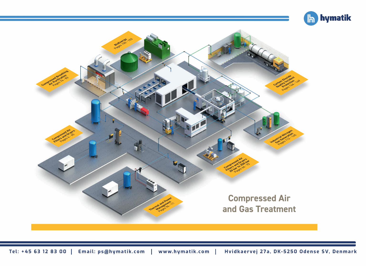
Selecting Parker purification equipment to comply with ISO8573-1:2010 air quality standard
ISO8573-1:2010 CLASS
Solid Particulate Water Oil
Wet Particulate Dry Particulate Vapour Total Oil (aerosol, liquid and vapour)
0 - - - OIL-X Grade AO + AA + OVR
1 OIL-X Grade AO + AA OIL-X Grade AO (M) + AA (M) Dryer sized for -70°C PDPOIL-X Grade AO + AA + OVR OIL-X Grade AO + AA +ACS
2 OIL-X Grade AO OIL-X Grade AO (M) Dryer sized for -40°C PDP OIL-X Grade AO + AA
3 OIL-X Grade AO OIL-X Grade AO (M) Dryer sized for -20°C PDP OIL-X Grade AO
4 OIL-X Grade AO OIL-X Grade AO (M) Dryer sized for +3°C PDP OIL-X Grade AO
5 OIL-X Grade AO OIL-X Grade AO (M) Dryer sized for +7°C PDP -
6 - - Dryer sized for +10°C PDP -
For further information relating to ISO Compressed Air Quality Standards please refer to our white paper ‘Introduction to ISO Compressed Air Quality Standards’. Available at parker.com/gsfe
Simple guidelines for the selection of purification equipment1. Purification equipment is installed to provide air quality, therefore you must first of all identify the quality of compressed air
required for the compressed air leaving the compressor room and for each point of use on the compressed air system.
2. The air quality required at each point of use may differ dependent upon the application.
3. Using the quality classifications shown in ISO8573-1 will allow easy selection of purification equipment.
4. ISO8573-1:2010 is the latest edition of the standard, however some facilities may still be operating on older revisions.
5. Specifying air quality as ISO8573-1, ISO8573-1:1991 or ISO8573-1:2001 refers to the previous editions of the standard and may result in a different quality of delivered compressed air.
6. Ensure any ISO8573-1 air purity classifications are written in full and include the revision year to allow for correct product selection.
7. Remember - Oil-free compressor installations require the same filtration considerations as oil lubricated compressor installations.

6
Compressed Air Filters and Dryers
FOOD / BEVERAGE / PHARMACEUTICAL - DIRECT CONTACT APPLICATIONS
Cost effective system designTo achieve the stringent air quality levels required for today’s modern production facilities, a careful approach to system design, commissioning and operation must be employed.
Treatment at one point alone is not enough and it is highly recommended that the compressed air is treated in the compressor room to a level that will provide general purpose air to the site and also protect the distribution piping. Point of use purification should also be employed, not only to remove
any contamination remaining in the distribution system, but also with specific attention on the quality of air required by each application. This approach to system design ensures that air is not ‘over treated’ and provides the most cost effective solution to high quality compressed air.
STERILE - FOOD / BEVERAGE / PHARMA GRADE OIL-FREE
AIR FORCRITICAL APPLICATIONS
ISO8573-1:2010 Class 1:2:0
FOOD / BEVERAGE / PHARMA GRADE OIL-FREE AIR FOR
DIRECT CONTACT APPLICATIONS
ISO8573-1:2010 Class 1:2:0
NON CONTACT APPLICATIONS
ISO8573-1:2010 Class 2:5:-*
WS AO
HIGH FLOW TETPOR II
FBP ADSORPTION DRYER
REFRIGERATION DRYER
AIR RECEIVER
COMPRESSOR
IMPORTANT NOTE:THE PURIFICATION EQUIPMENT REQUIREMENTS ARE IDENTICALFOR BOTH OIL-FREE AND OIL LUBRICATED COMPRESSORS.
AO (M)
OVR
AO (M) * Oil Classification dependent upon
contamination already in piping
STERILE - FOOD / BEVERAGE / PHARMA GRADE OIL-FREE
AIR FORCRITICAL APPLICATIONS
ISO8573-1:2010 Class 1:2:0
FOOD / BEVERAGE / PHARMA GRADE OIL-FREE AIR FOR
DIRECT CONTACT APPLICATIONS
ISO8573-1:2010 Class 1:2:0
NON CONTACT APPLICATIONS
ISO8573-1:2010 Class 2:2:-*
WS AO AA
HIGH FLOW TETPOR II
AA (M)
OVR MX OR MXLE
ADSORPTION DRYER
AIR RECEIVER
COMPRESSOR
IMPORTANT NOTE:THE PURIFICATION EQUIPMENT REQUIREMENTS ARE IDENTICALFOR BOTH OIL-FREE AND OIL LUBRICATED COMPRESSORS.
AO (M)
OVR
OVR
AA (M)
AO (M)
AO (M)
* Oil Classification dependent upon contamination already in piping
AO (M)
ISO8573-1:2010 Class 2.2.0 ≤-40°C (≤-40°F) PDP
AA
FBP ADSORPTION DRYER
Typical ApplicationsDirect contact / in-direct contact applications in food manufacturing / beverage bottling / pharmaceutical manufacturing / dairies / breweries / wineries / distilleries (In accordance with BCAS Best Practice Guideline 102 Food & Beverage Grade Compressed Air).
COMPRESSOR ROOM APPLICATION
COMPRESSOR ROOM APPLICATION

7
www.parker.com/gsfe
HIGH QUALITY TECHNICALLY OIL-FREE AIR
Typical Oil-Free Air ApplicationsBlow Moulding of Plastics e.g. P.E.T. BottlesElectronics ManufacturingCDA systems for electronics manufacturing Film processingCritical instrumentationAdvanced pneumaticsAir blast circuit breakers
GENERAL PURPOSE AIR WITH OIL-FREE AIR FOR CRITICAL APPLICATIONS
Typical General Purpose ApplicationsGeneral ring main protection Pre-filtration to point of use adsorption air dryers Plant automation Air logisticsPneumatic toolsGeneral instrumentationMetal stamping
Decompression chambersCosmetic productionMedical airDental airLasers and opticsRoboticsSpray painting
ForgingGeneral industrial assembly(no external piping)Air conveying (non food)Air motors Workshop (tools)Garage (tyre filling)
Temperature control systemsBlow gunsGauging equipmentRaw material mixingSand / bead blasting
HIGH QUALITY OIL-FREE AIR
ISO 8573-1:2010 Class 1:1:0 ISO 8573-1:2010 Class 1:2:0 ISO 8573-1:2010 Class 1:3:0
GENERAL USE ISO 8573-1:2010 Class 1:1:2 ISO 8573-1:2010 Class 1:2:2 ISO 8573-1:2010 Class 1:3:2
WS AO AA
WS AO
AO (M)
AO (M)
AA (M)
OVR
AA
PARKER ADSORPTION OR HYBRID DRYER
AIR RECEIVER
AIRRECEIVER
COMPRESSOR
COMPRESSOR REFRIGERATION DRYER
OVR
IMPORTANT NOTE:THE PURIFICATION EQUIPMENT REQUIREMENTS ARE IDENTICAL FOR BOTH OIL-FREE AND OIL LUBRICATED COMPRESSORS. THE REQUIREMENTS FOR BREATHABLE QUALITY AIR ARE NOT COVERED IN ISO8573 REFER TO BREATHING AIR STANDARDS FOR THE COUNTRY OF INSTALLATION.
GENERAL PURPOSE AIR ISO 8573-1:2010 Class 2:5:2
GENERAL PURPOSE OIL-FREE AIR
ISO 8573-1:2010 Class 1:5:0
STERILE AIR FOR CRITICAL APPLICATIONS
ISO 8573-1:2010 Class 1:1:0 ISO 8573-1:2010 Class 1:2:0 ISO 8573-1:2010 Class 1:3:0
OVR
AA (M)
AA (M)
AO (M)
AO (M)
OFASOil Free Air System
AA (M)
HIGH QUALITY OIL-FREE AIR
ISO 8573-1:2010 Class 2:1:0 ISO 8573-1:2010 Class 2:2:0 ISO 8573-1:2010 Class 2:3:0
HIGH FLOW TETPOR II
IMPORTANT NOTE:THE PURIFICATION EQUIPMENT REQUIREMENTS ARE IDENTICAL FOR BOTH OIL-FREE AND OIL LUBRICATED COMPRESSORS. THE REQUIREMENTS FOR BREATHABLE QUALITY AIR ARE NOT COVERED IN ISO8573 REFER TO BREATHING AIR STANDARDS FOR THE COUNTRY OF INSTALLATION.
AO (M)
AA (M)
Air bearingsPipeline purgingMeasuring equipmentBlanketingModified Atmosphere PackagingPre-treatment for on-site gas generation
ISO 8573-1:2010 Class 2.1.2 -70°C (-100°F) PDP ISO 8573-1:2010 Class 2.2.2 -40°C (-40°F) PDP ISO 8573-1:2010 Class 2.3.2 -20°C (-4°F) PDP
COMPRESSOR ROOM APPLICATION
COMPRESSOR ROOM APPLICATION

8
Selecting the right purification products for your compressed air systemTo achieve the degree of air quality specified by ISO8573-1, a careful approach to system design, commissioning and operation must be adopted.
Parker recommends that compressed air is treated:
• Prior to entry into the distribution system
• At critical usage points and applications
This ensures that contamination already in the distribution system is removed.
Purification equipment should be installed where the air is at the lowest possible temperature (i.e. downstream of after-coolers and air receivers). Point-of-use
purification equipment should be installed as close as possible to the application.
In order to correctly size purification equipment, there are a number of primary operating parameters that must be obtained from the users site. These are:
• The MAXIMUM compressed air flow rate into the filters / dryer
• The MINIMUM operating pressure into the filters / dryer
• The MAXIMUM operating temperature into the filters / dryer
• The MAXIMUM ambient air temperature where the equipment is to be installed
• The required dewpoint (dryers)
Individually, each of the primary operating parameters can influence product sizing however collectively they can have a major impact on product sizing and performance.
With the primary operating parameters, basic product selections can be made, however additional information may also be required to finalise product selection. Secondary parameters include:
• Minimum operating temperature
• Preferred pipe connections
• Available electrical supply (voltage / phase / frequency)
• Customers preference regarding drains, controllers or other options
Compressed Air Filters and Dryers

9
www.parker.com/gsfe
Frequently Asked Questions: High / Low Temperatures High Temperatures Maximum temperature (inlet & ambient) for dryers is 50°C or 122°F. For temperatures above this it is more cost effective to install an after-cooler than oversize a dryer. Also as a dryer increases in size, so does the volume of purge required to regenerate the dryer. Fitting an after-cooler is also more cost effective in terms of energy consumption.
Low Temperatures Freezing water causes damage to a dryer therefore as the temperature approaches freezing, the dryer and ancillaries need protection. Sub-zero temperatures also affect the function of seals and electronics.
• Always keep purification equipment under shelter and out of cold wind / direct air blasts
• Trace heat & insulate anywhere where moisture is present i.e. Inlet filtration / drain lines / Inlet valves / columns / exhaust valves
Cost Engagement
Cost Engagement
Cost Engagement
Cost Engagement
Cost Engagement
Why is MAXIMUM Flow Rate Important?Filtration: As compressed air flow rates increase, contamination levels increase and a larger filtration surface area is required to ensure adequate filtration performance, low pressure drop and 12 month lifetime of filter elements.
Dryers: As compressed air flow rates increase, the amount of water vapour the dryer must remove also increases.
Adsorption dryers must be sized on the highest flow rate to ensure the desiccant bed is large enough to provide the correct contact time and dewpoint.
Refrigeration dryers must be sized to ensure the heat exchanger is large enough and has enough cooling capacity.
Why is MINIMUM Inlet Pressure Important?Dryers: As pressure decreases, the volume of compressed air increases, as does the water vapour content, therefore the amount of water vapour the dryer must remove also increases. Dryers must be sized for minimum inlet pressure to account for the increased amount of water vapour present.
Why is MAXIMUM Inlet Temperature Important?Dryers: As the temperature of the compressed air increases, so does the water vapour content, therefore the amount of water vapour the dryer must remove also increases. Dryers must be sized for maximum inlet temperature to account for the increased amount of water vapour present.
Why is MAXIMUM Ambient Temperature Important?Refrigeration & Tandem Technology Dryers: Air cooled refrigeration & Tandem Technology dryers use ambient air for heat exchange.
The lower the ambient air temperature, the better the heat exchange process
Poor ventilation and / or high ambient air temperatures will result in loss of dewpoint.
Why Correct a Dryer for Dewpoint? Adsorption Dryers: Dewpoint is derived from contact time between the air and the desiccant material, lower dewpoint's typically require the dryer to be de-rated to provide more contact time.
Refrigeration Dryers: The size of the heat exchangers affects the cooling capacity, too little cooling capacity results in poor dewpoint.

10
Flow Rates
To correctly select a separator model, the flow rate of the separator must be adjusted for the minimum operating (inlet) pressure at the point of installation.1. Obtain the minimum operating (inlet) pressure and maximum compressed air flow rate at the inlet of the filter.2. Select the correction factor for minimum inlet pressure from the CFMIP table (always round down e.g. for 5.3 bar, use 5 bar correction factor)3. Calculate the minimum filtration capacity. Minimum Filtration Capacity = Compressed Air Flow Rate x CFMIP4. Using the minimum filtration capacity, select a filter model from the flow rate tables above (filter selected must have a flow rate equal to or
greater than the minimum filtration capacity).
MinimumInlet Pressure
bar g 1 2 3 4 5 6 7 8 9 10 11 12 13 14 15 16
psi g 15 29 44 58 73 87 100 116 131 145 160 174 189 203 218 232
Correction Factor 4.00 2.63 2.00 1.59 1.33 1.14 1.00 0.94 0.89 0.85 0.82 0.79 0.76 0.73 0.71 0.68
Stated flows are for operation at 7 bar (g) (102 psi g) with reference to 20°C, 1 bar (a), 0% relative water vapour pressure. For flows at other pressures, apply the correction factors shown below.
Product Selection & Correction Factors
Separator Coding Example
Grade Model Pipe Size Thread Drain
Option
Incident Monitor Option
WS
P & 3 digit code
denotes filter
housing size
Letter denotes
pipe size
G = BSPPN = NPT F = Float I = Indicator
X = None
Example code
WS P010 A G F X
Model Pipe Size L/S m³/min m³/hr cfm
WSP010A FX 1/4" 10 0.6 36 21
WSP010B FX 3/8" 10 0.6 36 21
WSP010C FX 1/2" 10 0.6 36 21
WSP015C FX 1/2" 40 2.4 144 85
WSP020D FX 3/4" 40 2.4 144 85
WSP025D FX 3/4" 110 6.6 396 233
WSP025E FX 1" 110 6.6 396 233
WSP030G FX 11/2" 110 6.6 396 233
WSP035G FX 11/2" 350 21 1260 742
WSP040H FX 2" 350 21 1260 742
WSP045I FX 21/2" 350 21 1260 742
WSP050I FX 21/2" 800 48 2880 1695
WSP055J FX 3" 800 48 2880 1695
WSP060K FX 4" 1000 60 3600 2119
Filtration Grade Water Separator Models
Minimum Operating Pressure
Maximum Operating Pressure
Minimum OperatingTemperature
Maximum Operating Temperature
bar g psi g bar g psi g ºC ºF ºC ºF
WSP010A FX - P055J FX 1 15 16 232 2 35 80 176
P060K FX 1 15 16 232 2 35 66 150
Separation Performance
Technical Data
20 40 60 80 10090
91
92
93
94
95
WS010WS015 & WS020WS025 & WS030WS035, WS040 & WS045WS055
30 50 70 90
96
97
98
99
100
20 40 60 80 10090
91
92
93
94
95
WS010WS015 & WS020WS025 & WS030WS035, WS040 & WS045WS055
30 50 70 90
96
97
98
99
100
OIL-X Liquid Separators
Differential Pressure Versus Flow
20 40 60 80 10090
91
92
93
94
95
WS010WS015 & WS020WS025 & WS030WS035, WS040 & WS045WS055
30 50 70 90
96
97
98
99
100
% Rated Flow
Liquid Reduction % Versus Flow
Diff
eren
tial
Pre
ssur
e (m
bar
)
% Rated Flow
Compressed Air Filters
CFMIP - Correction Factor Minimum Inlet Pressure

11
www.parker.com/gsfe
W
H
D
W
H
D
010 - 030 035 - 060
ModelHeight (H) Width (W) Depth (D) Weight
mm ins mm ins mm ins kg lbs
010A 180 7.09 76 2.99 65 2.56 0.80 1.76
010B 180 7.09 76 2.99 65 2.56 0.79 1.75
010C 180 7.09 76 2.99 65 2.56 0.78 1.72
015C 238 9.37 89 3.5 84 3.31 1.08 2.39
020D 238 9.37 89 3.5 84 3.31 1.35 2.98
025D 277 10.9 120 4.72 115 4.53 2.64 5.83
025E 277 10.9 120 4.72 115 4.53 2.64 5.83
030G 367 14.45 120 4.72 115 4.53 2.54 5.61
035G 440 17.32 164 6.46 157 6.18 6.69 14.74
040H 440 17.32 164 6.46 157 6.18 6.46 14.23
045I 440 17.32 164 6.46 157 6.18 6.28 13.85
050I 516 20.31 192 7.56 183 7.20 10.80 23.81
055J 516 20.31 192 7.56 183 7.20 10.83 23.89
060K 847 33.3 420 16.54 282 11.10 10.83 23.89
Weights & Dimensions
Model Catalogue NumberWater Separator
010A WSP010AGFX
010B WSP010BGFX
010C WSP010CGFX
015C WSP015CGFX
020D WSP020DGFX
025D WSP025DGFX
025E WSP025EGFX
030G WSP030GGFX
035G WSP035GGFX
040H WSP040HGFX
045I WSP045IGFX
050I WSP050IGFX
055J WSP055JGFX
060K WSP060KGFX
Parker Catalogue Numbers (BSPP Models)

12
To correctly select a separator model, the flow rate of the separator must be adjusted for the minimum operating (inlet) pressure at the point of installation.1. Obtain the minimum operating (inlet) pressure and maximum compressed air flow rate at the inlet of the filter.2. Select the correction factor for minimum inlet pressure from the CFMIP table (always round down e.g. for 5.3 bar, use 5 bar correction factor)3. Calculate the minimum filtration capacity. Minimum Filtration Capacity = Compressed Air Flow Rate x CFMIP 4. Using the minimum filtration capacity, select a filter model from the flow rate tables above (filter selected must have a flow rate equal to or greater than
the minimum filtration capacity).
MinimumInlet Pressure
bar g 1 2 3 4 5 6 7 8 9 10 11 12 13 14 15 16
psi g 15 29 44 58 73 87 100 116 131 145 160 174 189 203 218 232
Correction Factor 4.00 2.63 2.00 1.59 1.33 1.14 1.00 0.94 0.89 0.85 0.82 0.79 0.76 0.73 0.71 0.68
Stated flows are for operation at 7 bar (g) (102 psi g) with reference to 20°C, 1 bar (a), 0% relative water vapour pressure. For flows at other pressures, apply the correction factors shown below.
Product Selection & Correction Factors
Example code
SFH067NModel
Pipe SizeL/S m³/min m³/hr cfm
Inlet Outlet
SFH029 DN80 DN80 490 29.4 1764 1038
SFH030 DN100 DN80 500 30.0 1800 1059
SFH037 DN100 DN100 610 36.6 2196 1293
SFH038 DN125 DN100 633 38.0 2280 1342
SFH066 DN125 DN125 1093 65.6 3936 2317
SFH067 DN150 DN125 1117 67.0 4020 2366
SFH088 DN150 DN150 1473 88.4 5304 3122
SFH089 DN200 DN150 1483 89.0 5340 3143
SFH097 DN200 DN200 1618 97.1 5826 3429
SFH142 DN250 DN200 2365 141.9 8514 5011
SFH180 DN300 DN200 2992 179.5 10770 6339
SFH209 DN350 DN200 3485 209.1 12546 7385
Filtration Grade Water Separator Models
Minimum Operating Pressure
Maximum Operating Pressure
Minimum OperatingTemperature
Maximum Operating Temperature
bar g psi g bar g psi g ºC ºF ºC ºF
SFH SFH029N - SFH209N 1 15 16 232 2 35 60 140
Flow Rates
Technical Data
Separator Coding Example
Compressed Air Filters
SFH Liquid Separators (Carbon Steel)
CFMIP - Correction Factor Minimum Inlet Pressure

13
www.parker.com/gsfe
ModelHeight (H) Width (W) Depth (D) Weight
mm ins mm ins mm ins kg lbs
SFH029 720 28.3 400 15.7 200 7.9 28 62
SFH030 720 28.3 400 15.7 200 7.9 29 64
SFH037 880 34.6 460 18.1 230 9.1 48 106
SFH038 880 34.6 460 18.1 230 9.1 49 108
SFH066 980 38.6 550 21.7 260 10.2 55 121
SFH067 980 38.6 550 21.7 260 10.2 56 123
SFH088 1060 41.7 570 22.4 290 11.4 82 180
SFH089 1060 41.7 570 22.4 290 11.4 85 187
SFH097 1160 45.7 660 26.0 320 12.6 126 277
SFH142 1255 49.4 680 26.8 351 13.8 148 326
SFH180 1455 57.3 750 29.5 390 15.4 160 352
SFH209 1655 65.2 830 32.7 430 16.9 205 451
Weights & Dimensions
Model Catalogue NumberWater Separator
SFH029 SFH029N
SFH030 SFH030N
SFH037 SFH037N
SFH038 SFH038N
SFH066 SFH066N
SFH067 SFH067N
SFH088 SFH088N
SFH089 SFH089N
SFH097 SFH097N
SFH142 SFH142N
SFH180 SFH180N
SFH209 SFH209N
SFH029 - SFH038 = ½" BSP SFH066 - SFH209 = 1" BSP
W
H
Parker Catalogue Numbers
14
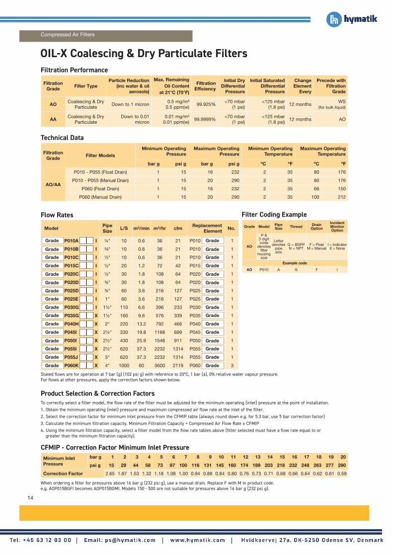
Flow Rates
Filtration Grade Filter Type
Particle Reduction (inc water & oil
aerosols)
Max. Remaining Oil Content
at 21°C (70°F)
Filtration Efficiency
Initial Dry Differential
Pressure
Initial Saturated Differential
Pressure
Change Element
Every
Precede with Filtration
Grade
AO Coalescing & Dry Particulate
Down to 1 micron0.5 mg/m³
0.5 ppm(w)99.925%
<70 mbar (1 psi)
<125 mbar (1.8 psi)
12 monthsWS
(for bulk liquid)
AA Coalescing & Dry Particulate
Down to 0.01 micron
0.01 mg/m³ 0.01 ppm(w)
99.9999%<70 mbar
(1 psi)<125 mbar
(1.8 psi)12 months AO
Filtration Grade Filter Models
Minimum Operating Pressure
Maximum Operating Pressure
Minimum Operating Temperature
Maximum Operating Temperature
bar g psi g bar g psi g ºC ºF ºC ºF
AO/AA
P010 - P055 (Float Drain) 1 15 16 232 2 35 80 176
P010 - P055 (Manual Drain) 1 15 20 290 2 35 80 176
P060 (Float Drain) 1 15 16 232 2 35 66 150
P060 (Manual Drain) 1 15 20 290 2 35 100 212
To correctly select a filter model, the flow rate of the filter must be adjusted for the minimum operating (inlet) pressure at the point of installation.1. Obtain the minimum operating (inlet) pressure and maximum compressed air flow rate at the inlet of the filter.2. Select the correction factor for minimum inlet pressure from the CFMIP table (always round down e.g. for 5.3 bar, use 5 bar correction factor)3. Calculate the minimum filtration capacity. Minimum Filtration Capacity = Compressed Air Flow Rate x CFMIP 4. Using the minimum filtration capacity, select a filter model from the flow rate tables above (filter selected must have a flow rate equal to or
greater than the minimum filtration capacity).
Minimum Inlet Pressure
bar g 1 2 3 4 5 6 7 8 9 10 11 12 13 14 15 16 17 18 19 20
psi g 15 29 44 58 73 87 100 116 131 145 160 174 189 203 218 232 248 263 277 290
Correction Factor 2.65 1.87 1.53 1.32 1.18 1.08 1.00 0.94 0.88 0.84 0.80 0.76 0.73 0.71 0.68 0.66 0.64 0.62 0.61 0.59
Stated flows are for operation at 7 bar (g) (102 psi g) with reference to 20°C, 1 bar (a), 0% relative water vapour pressure. For flows at other pressures, apply the correction factors shown below.
Filtration Performance
Technical Data
Product Selection & Correction Factors
When ordering a filter for pressures above 16 bar g (232 psi g), use a manual drain. Replace F with M in product code. e.g. AOP015BGFI becomes AOP015BGMI. Models 150 - 500 are not suitable for pressures above 16 bar g (232 psi g).
Filter Coding ExampleGrade Model Pipe
Size Thread Drain Option
Incident Monitor Option
AO
P & 3 digit code
denotes filter
housing size
Letter denotes
pipe size
G = BSPPN = NPT
F = FloatM = Manual
I = IndicatorX = None
Example code
AO P010 A G F I
Model Pipe Size L/S m³/min m³/hr cfm Replacement
Element No.
P010A I 1/4" 10 0.6 36 21 P010 1
P010B I 3/8" 10 0.6 36 21 P010 1
P010C I 1/2" 10 0.6 36 21 P010 1
P015C I 1/2" 20 1.2 72 42 P015 1
P020C I 1/2" 30 1.8 108 64 P020 1
P020D I 3/4" 30 1.8 108 64 P020 1
P025D I 3/4" 60 3.6 216 127 P025 1
P025E I 1" 60 3.6 216 127 P025 1
P030G I 11/2" 110 6.6 396 233 P030 1
P035G X 11/2" 160 9.6 576 339 P035 1
P040H X 2" 220 13.2 792 466 P040 1
P045I X 21/2" 330 19.8 1188 699 P045 1
P050I X 21/2" 430 25.9 1548 911 P050 1
P055I X 21/2" 620 37.3 2232 1314 P055 1
P055J X 3" 620 37.3 2232 1314 P055 1
P060K X 4" 1000 60 3600 2119 P060 3
Grade
Grade
Grade
Grade
Grade
Grade
Grade
Grade
Grade
Grade
Grade
Grade
Grade
Grade
Grade
Grade
Grade
Grade
Grade
Grade
Grade
Grade
Grade
Grade
Grade
Grade
Grade
Grade
Grade
Grade
Grade
Grade
OIL-X Coalescing & Dry Particulate Filters
CFMIP - Correction Factor Minimum Inlet Pressure
Compressed Air Filters

15
www.parker.com/gsfe
ModelHeight (H) Width (W) Depth (D) Weight
mm ins mm ins mm ins kg lbs
010A 180 7.09 76 2.99 65 2. 56 0.84 1.86
010B 180 7.09 76 2.99 65 2. 56 0.84 1.84
010C 180 7.09 76 2.99 65 2. 56 0.82 1.81
015C 238 9.37 89 3.5 84 3.31 1.16 2.55
020C 238 9.37 89 3.5 84 3.31 1.17 2.58
020D 238 9.37 89 3.5 84 3.31 1.44 3.19
025D 277 10.9 120 4.72 115 4.53 2.14 4.71
025E 277 10.9 120 4.72 115 4.53 2.69 5.92
030G 367 14.45 120 4.72 115 4.53 3.04 6.70
035G 440 20.9 164 6.46 157 6.18 6.90 15.21
040H 532 24.5 164 6.46 157 6.18 7.30 16.09
045I 532 24.5 164 6.46 157 6.18 7.10 15.65
050I 654 29.3 192 7.56 183 7.20 10.30 22.71
055I 844 36.8 192 7.56 183 7.20 15.90 33.05
055J 844 36.8 192 7.56 183 7.20 15.30 33.73
060K 847 33.3 420 16.54 282 11.10 44.50 98.11
Weights & Dimensions
ModelCatalogue NumberGeneral Purpose
Coalescing Filters
Catalogue NumberGeneral Purpose
Dry Particulate Filters
Catalogue NumberHigh Efficiency
Coalescing Filters
Catalogue NumberHigh Efficiency
Dry Particulate Filters
P010A AOP010AGFI AOP010AGMI AAP010AGFI AAP010AGMI
P010B AOP010BGFI AOP010BGMI AAP010BGFI AAP010BGMI
P010C AOP010CGFI AOP010CGMI AAP010CGFI AAP010CGMI
P015C AOP015CGFI AOP015CGMI AAP015CGFI AAP015CGMI
P020C AOP020CGFI AOP020CGMI AAP020CGFI AAP020CGMI
P020D AOP020DGFI AOP020DGMI AAP020DGFI AAP020DGMI
P025D AOP025DGFI AOP025DGMI AAP025DGFI AAP025DGMI
P025E AOP025EGFI AOP025EGMI AAP025EGFI AAP025EGMI
P030G AOP030GGFI AOP030GGMI AAP030GGFI AAP030GGMI
P035G AOP035GGFX AOP035GGMX AAP035GGFX AAP035GGMX
P040H AOP040HGFX AOP040HGMX AAP040HGFX AAP040HGMX
P045I AOP045IGFX AOP045IGMX AAP045IGFX AAP045IGMX
P050I AOP050IGFX AOP050IGMX AAP050IGFX AAP050IGMX
P055I AOP055IGFX AOP055IGMX AAP055IGFX AAP055IGMX
P055J AOP055JGFX AOP055JGMX AAP055JGFX AAP055JGMX
P060K AOP060KGFX AOP060KGMX AAP060KGFX AAP060KGMX
W
H
D
W
H
D
010 - 030 035 - 060
Parker Catalogue Numbers (BSPP Models)

16
Filtration Grade
Filter Type
Particle Reduction (inc water & oil
aerosols)
Max. Remaining Oil Content
at 21°C (70°F)
Filtration Efficiency
Initial Dry Differential
Pressure
Initial Saturated Differential
Pressure
Change Element
Every
Precede with Filtration
Grade
AO Coalescing & Dry Particulate
Down to 1 micron0.5 mg/m³
0.5 ppm(w)99.925%
<70 mbar (1 psi)
<125 mbar (1.8 psi)
12 monthsWS (for bulk
liquid)
AA Coalescing & Dry Particulate
Down to 0.01 micron
0.01 mg/m³ 0.01 ppm(w)
99.9999%<70 mbar
(1 psi)<125 mbar
(1.8 psi)12 months AO
ACS Oil Vapour Reduction
N/A0.003 mg/m³
0.003 ppm(w)N/A
<140 mbar (2 psi)
N/AWhen oil vapour is detected
AO+AA
FiltrationGrade Filter Models
Minimum Operating Pressure
Maximum Operating Pressure
Minimum Operating Temperature
Maximum Operating Temperature
bar g psi g bar g psi g ºC ºF ºC ºF
AO/AA065 - 095 (Electronic Drain) 1 15 16 232 2 35 60 140
065 - 095 (Manual Drain) 1 15 16 232 2 35 100 212
ACS 065 - 095 (Manual Drain) 1 15 16 232 2 35 50 122
To correctly select a filter model, the flow rate of the filter must be adjusted for the minimum operating (inlet) pressure at the point of installation.1. Obtain the minimum operating (inlet) pressure and maximum compressed air flow rate at the inlet of the filter.2. Select the correction factor for minimum inlet pressure from the CFMIP table (always round down e.g. for 5.3 bar, use 5 bar correction factor)3. Calculate the minimum filtration capacity. Minimum Filtration Capacity = Compressed Air Flow Rate x CFMIP 4. Using the minimum filtration capacity, select a filter model from the flow rate tables above (filter selected must have a flow rate equal to or
greater than the minimum filtration capacity).
MinimumInlet Pressure
bar g 1 2 3 4 5 6 7 8 9 10 11 12 13 14 15 16
psi g 15 29 44 58 73 87 100 116 131 145 160 174 189 203 218 232
Correction Factor 2.65 1.87 1.53 1.32 1.18 1.08 1.00 0.94 0.88 0.84 0.80 0.76 0.73 0.71 0.68 0.66
Stated flows are for operation at 7 bar (g) (102 psi g) with reference to 20°C, 1 bar (a), 0% relative water vapour pressure. For flows at other pressures, apply the correction factors shown below.
Filtration Performance
Technical Data
Product Selection & Correction Factors
Filter Coding Example
Important Note:Using the same filter housings as their coalescing and dry particulate counterparts in the OIL-X range, Grade ACS filter elements differ in that they utilise a deep wrapped bed of carbon cloth to adsorb oil vapour.
It is important to note, in-line adsorption filter elements have a different life span compared to coalescing and dry particulate filters and require more frequent element changes. Should a 12 month service period be required, Parker OIL-X Grade OVR oil vapour reduction filters are recommended.
OIL-X Coalescing / Dry Particulate / Oil Vapour Reduction Filters (Carbon Steel)
Flow Rates
Grade Model Pipe Size Thread Drain
Option
Incident Monitor Option
AO AA
ACS
3 digit code
denotes filter
housing size
Letter denotes
pipe size
D = Din Flange
E = ElectronicM = Manual
I = IndicatorX = None
Example code
AO 090 P D E X
ModelPipe Size
L/S m³/min m³/hr cfmReplacement
ElementNo.
065ND X DN80 620 37.2 2232 1312 200 1
070OD X DN100 1240 74.4 4464 2625 200 2
075PD X DN150 1860 111.6 6696 3938 200 3
080PD X DN150 2480 148.8 8928 5251 200 4
085QD X DN200 3720 223.2 13392 7877 200 6
090RD X DN250 6200 372 22320 13129 200 10
095SD X DN300 8680 520.8 31248 18380 200 14
Grade
Grade
Grade
Grade
Grade
Grade
Grade
Grade
Grade
Grade
Grade
Grade
Grade
Grade
= Replace with drain type - E (electronic) or M (manual)
CFMIP - Correction Factor Minimum Inlet Pressure
Compressed Air Filters

17
www.parker.com/gsfe
ModelHeight (H) Width (W) Depth (D) Weight
mm ins mm ins mm ins kg lbs
065ND 1065 42 440 17.3 340 13.4 70 154
070OD 1152 45.4 500 19.7 405 16 97 214
075PD 1256 49.5 600 23.6 520 20.5 148 326
080PD 1332 52.4 650 25.6 580 22.8 187 412
085QD 1415 55.7 750 29.5 640 25.2 240 529
090RD 1603 63.1 1000 39.4 840 33 470 1036
095SD 1706 67.2 1050 41.3 910 35.8 580 1279
Weight & Dimensions
ModelCatalogue NumberGeneral Purpose
Coalescing Filters
Catalogue NumberGeneral Purpose
Dry Particulate Filters
Catalogue NumberHigh Efficiency
Coalescing Filters
Catalogue NumberHigh Efficiency
Dry Particulate Filters
Catalogue NumberOil Vapour Reduction
Filters
065N AO065NDEX AO065NDMX AA065NDEX AA065NDMX ACS065NDMX
070O AO070ODEX AO070ODMX AA070ODEX AA070ODMX ACS070ODMX
075P AO075PDEX AO075PDMX AA075PDEX AA075PDMX ACS075PDMX
080P AO080PDEX AO080PDMX AA080PDEX AA080PDMX ACS080PDMX
085Q AO085QDEX AO085QDMX AA085QDEX AA085QDMX ACS085QDMX
090P AO090RDEX AO090RDMX AA090RDEX AA090RDMX ACS090RDMX
095S AO095SDEX AO095SDMX AA095SDEX AA095SDMX ACS095SDMX
ModelCatalogue NumberGeneral Purpose
Coalescing Filters
Catalogue NumberGeneral Purpose
Dry Particulate Filters
Catalogue NumberHigh Efficiency
Coalescing Filters
Catalogue NumberHigh Efficiency
Dry Particulate Filters
065N AO065NDEI AO065NDMI AA065NDEI AA065NDMI
070O AO070ODEI AO070ODMI AA070ODEI AA070ODMI
075P AO075PDEI AO075PDMI AA075PDEI AA075PDMI
080P AO080PDEI AO080PDMI AA080PDEI AA080PDMI
085Q AO085QDEI AO085QDMI AA085QDEI AA085QDMI
090P AO090RDEI AO090RDMI AA090RDEI AA090RDMI
095S AO095SDEI AO095SDMI AA095SDEI AA095SDMI
W
HD
Approx 170mm
Parker Catalogue Numbers (No DPI)
Parker Catalogue Numbers (With DPI)

18
Flow Rates
Filtration Grade
Filter Type
Particle Reduction (inc water & oil
aerosols)
Max. Remaining Oil Content
at 21°C (70°F)
Filtration Efficiency
Initial Dry Differential
Pressure
Initial Saturated Differential
Pressure
Change Element
Every
Precede with Filtration
Grade
ACS Oil Vapour Reduction
N/A0.003 mg/m³
0.003 ppm(w)N/A
<140 mbar (2 psi)
N/AWhen oil vapour is detected
AO+AA
Filtration Grade Filter Models
Minimum Operating Pressure
Maximum Operating Pressure
Minimum Operating Temperature
Maximum Operating Temperature
bar g psi g bar g psi g ºC ºF ºC ºF
ACSP010 - P055 (Manual Drain) 1 15 20 290 2 35 50 122
P060 (Manual Drain) 1 15 20 290 2 35 50 122
To correctly select a filter model, the flow rate of the filter must be adjusted for the minimum operating (inlet) pressure at the point of installation.1. Obtain the minimum operating (inlet) pressure and maximum compressed air flow rate at the inlet of the filter.2. Select the correction factor for minimum inlet pressure from the CFMIP table (always round down e.g. for 5.3 bar, use 5 bar correction factor)3. Calculate the minimum filtration capacity. Minimum Filtration Capacity = Compressed Air Flow Rate x CFMIP 4. Using the minimum filtration capacity, select a filter model from the flow rate tables above (filter selected must have a flow rate equal to or greater than
the minimum filtration capacity).
MinimumInlet Pressure
bar g 1 2 3 4 5 6 7 8 9 10 11 12 13 14 15 16 17 18 19 20
psi g 15 29 44 58 73 87 100 116 131 145 160 174 189 203 218 232 248 263 277 290
Correction Factor 2.65 1.87 1.53 1.32 1.18 1.08 1.00 0.94 0.88 0.84 0.80 0.76 0.73 0.71 0.68 0.66 0.64 0.62 0.61 0.59
Stated flows are for operation at 7 bar (g) (102 psi g) with reference to 20°C, 1 bar (a), 0% relative water vapour pressure. For flows at other pressures, apply the correction factors shown below.
Filtration Performance
Technical Data
Product Selection & Correction Factors
Filter Coding Example
Grade Model Pipe Size Thread Drain
Option
Incident Monitor Option
ACS
P & 3 digit code
denotes filter
housing size
Letter denotespipe size
G = BSPPN = NPT M = Manual X = None
Example code
ACS P010 A G M X
Model Pipe Size L/S m³/min m³/hr cfm Replacement
Element No.
ACSP010A MX 1/4" 10 0.6 36 21 P010ACS 1
ACSP010B MX 3/8" 10 0.6 36 21 P010ACS 1
ACSP010C MX 1/2" 10 0.6 36 21 P010ACS 1
ACSP015C MX 1/2" 20 1.2 72 42 P015ACS 1
ACSP020C MX 1/2" 30 1.8 108 64 P020ACS 1
ACSP020D MX 3/4" 30 1.8 108 64 P020ACS 1
ACSP025D MX 3/4" 60 3.6 216 127 P025ACS 1
ACSP025E MX 1" 60 3.6 216 127 P025ACS 1
ACSP030G MX 11/2" 110 6.6 396 233 P030ACS 1
ACSP035G MX 11/2" 160 9.6 576 339 P035ACS 1
ACSP040H MX 2" 220 13.2 792 466 P040ACS 1
ACSP045I MX 21/2" 330 19.8 1188 699 P045ACS 1
ACSP050I MX 21/2" 430 25.9 1548 911 P050ACS 1
ACSP055I MX 21/2" 620 37.3 2232 1314 P055ACS 1
ACSP055J MX 3" 620 37.3 2232 1314 P055ACS 1
ACSP060K MX 4" 1000 60 3600 2119 P060ACS 3
G = BSPP / N=NPT
OIL-X Point Of Use Oil Vapour Reduction Filters
Compressed Air Filters
CFMIP - Correction Factor Minimum Inlet Pressure

19
www.parker.com/gsfe
ModelHeight (H) Width (W) Depth (D) Weight
mm ins mm ins mm ins kg lbs
010A 180 7.09 76 2.99 65 2. 56 0.84 1.86
010B 180 7.09 76 2.99 65 2. 56 0.84 1.84
010C 180 7.09 76 2.99 65 2. 56 0.82 1.81
015C 238 9.37 89 3.5 84 3.31 1.16 2.55
020C 238 9.37 89 3.5 84 3.31 1.17 2.58
020D 238 9.37 89 3.5 84 3.31 1.44 3.19
025D 277 10.9 120 4.72 115 4.53 2.14 4.71
025E 277 10.9 120 4.72 115 4.53 2.69 5.92
030G 367 14.45 120 4.72 115 4.53 3.04 6.70
035G 440 20.9 164 6.46 157 6.18 6.90 15.21
040H 532 24.5 164 6.46 157 6.18 7.30 16.09
045I 532 24.5 164 6.46 157 6.18 7.10 15.65
050I 654 29.3 192 7.56 183 7.20 10.30 22.71
055I 844 36.8 192 7.56 183 7.20 15.90 33.05
055J 844 36.8 192 7.56 183 7.20 15.30 33.73
060K 847 33.3 420 16.54 282 11.10 44.50 98.11
Weights & Dimensions
Model Catalogue Number Oil Vapour Reduction Filters
P010A ACSP010AGMX
P010B ACSP010BGMX
P010C ACSP010CGMX
P015C ACSP015CGMX
P020C ACSP020CGMX
P020D ACSP020DGMX
P025D ACSP025DGMX
P025E ACSP025EGMX
P030G ACSP030GGMX
P035G ACSP035GGMX
P040H ACSP040HGMX
P045I ACSP045IGMX
P050I ACSP050IGMX
P055I ACSP055IGMX
P055J ACSP055JGMX
P060K ACSP060KGMX
W
H
D
W
H
D
010 - 030 040 - 060
Parker Catalogue Numbers (BSPP Models)

20
Stated flows are for operation at 7 bar (g) (102 psi g) with reference to 20°C, 1 bar (a), 0% relative water vapour pressure. For flows at other pressures, apply the correction factors shown on the right.
Flow Rates
Filtration Performance
Technical Data
Filtration Grade
Filter Type
Particle Removal
(inc Water & Oil Aerosols)
Max. Remaining
Oil Content*
Filtration Efficiency
Initial Dry Differential
Pressure
Initial Saturated
Differential Pressure
Adsorbent Life
Precede with
Grade
OVR Oil Vapour Reduction
N/A≤ 0.003 mg/m3
≤ 0.003 ppm (w)N/A
<350 mbar <5 psi
N/A *12 months AO + AA
Filtration Grade Filter Models
Minimum Operating Pressure
Maximum Operating Pressure
Minimum Operating Temperature
Maximum Operating Temperature
bar g psi g bar g psi g ºC ºF ºC ºF
OVR 300H XX - 550I XX 1 15 16 232 2 35 50 122
Model Pipe Size L/s m3/min m3/hr cfm Replacement Cartridge
No. Required
OVR300H XX 2" 87 5.2 314 185 300OVR 1
OVR350H XX 2" 177 10.6 637 375 350OVR 1
OVR400H XX 2" 354 21.2 1274 750 400OVR 1
OVR450I XX 21/2" 531 31.9 1911 1125 450OVR 1
OVR500I XX 21/2" 708 42.5 2549 1500 500OVR 1
OVR550I XX 21/2" 885 53.1 3186 1875 550OVR 1
2 x OVR550I XX 21/2" 1770 106.2 6371 3750 550OVR 2
3 x OVR550I XX 21/2" 2655 159.3 9557 5625 550OVR 3
4 x OVR550I XX 21/2" 3540 212.4 12743 7500 550OVR 4
5 x OVR550I XX 21/2" 4424 265.5 15928 9375 550OVR 5
Product Selection & Correction Factors 1. System Information Required for OVR Sizing & Selection• Minimum pressure at the inlet of the OVR • Compressor type (oil lubricated or oil free)
• Maximum inlet temperature at the inlet of the OVR (highest summer inlet temp) • Maximum compressed air flow rate
• Dewpoint of the compressed air (is the OVR to be • Oil vapour concentration expected at the inlet of the OVR installed before or after a dryer) (default is 0.05 mg/m³)
2. Select Correction Factors• For minimum inlet pressure, select a correction factor from the CFMIP table that corresponds to the minimum inlet pressure of the compressed air system, remembering to always round down e.g. for 5.3 bar g use the 5 bar g correction factor.
• For maximum inlet temperature there are two tables, one for use with an oil lubricated compressor, the other for oil free compressor. Select a correction factor from the CFMIT table for the relevant compressor type, remembering to always round up e.g. for 37°C use the 40°C correction factor.
• For pressure dewpoint, select a correction factor from the CFID table.
• For oil vapour concentration, select a correction factor from the CFIV table, remembering to always round up e.g. for 3.25g/m³ use the correction factor for 4mg/m3.
3. Calculate Minimum Filtration capacity• Minimum Filtration Capacity = Compressed Air Flow x CFMIT x CFMIP x CFID x CFIV.
• Using the minimum filtration capacity, select an OVR model from the flow rate tables. The OVR model selected must have a flow rate equal to or greater than the minimum filtration capacity.
• If the minimum filtration capacity exceeds the maximum values of the models shown within the tables, please contact Parker for advice regarding larger multi-banked units.
OIL-X OVR Plant Scale Oil Vapour Reduction
G = BSPP / N=NPT
*At system operating temperature and when corrected to match system conditions.
Compressed Air Filters

21
www.parker.com/gsfe
MinimumInlet Pressure
bar g 3 4 5 6 7 8 9 10 11 12 13 14 15 16
psi g 44 58 73 87 100 116 131 145 160 174 189 203 218 232
Correction Factor 2.00 1.60 1.33 1.14 1.00 1.00 1.00 1.00 1.00 1.00 1.00 1.00 1.00 1.00
Oil Lubricated Compressors Oil-Free Compressors
°C °F Correction Factor °C °F Correction Factor
25 77 1.00 25 77 1.00
30 86 1.00 30 86 1.00
35 95 1.00 35 95 1.00
40 104 1.25 40 104 1.02
45 113 1.55 45 113 1.04
50 122 1.90 50 122 1.05
Installation Correction Factor
After Dryer 1.00Before Dryer 4.00
Inlet Vapour Concentration mg/m3 0.05 0.1 0.2 0.3 0.4 0.5 0.6 0.7 0.8 0.9 1.0 2.0 3.0 4.0 5.0
Correction Factor 1 2 4 6 8 10 12 14 16 18 20 40 60 80 100
Weight & Dimensions
ModelsHeight (H) Width (W) Depth (D) Weight
mm ins mm ins mm ins kg lbs
OVR300 792 31.2 245 9.6 230 9.1 28.5 62.8
OVR350 1009 39.7 590 23.2 550 21.7 62.5 137.8
OVR400 1009 39.7 735 28.9 550 21.7 71.5 157.6
OVR450 1009 39.7 888 35.0 550 21.7 92.8 204.6
OVR500 1009 39.7 1065 41.9 550 21.7 100.6 221.8
OVR550 1009 39.7 1234 48.6 550 21.7 122.0 269.0
Model Catalogue NumberPlant Scale Oil Vapour Reduction (BSPP)
Catalogue NumberPlant Scale Oil Vapour Reduction (NPT)
OVR300 OVR300HGXX OVR300HNXX
OVR350 OVR350HGXX OVR350HNXX
OVR400 OVR400HGXX OVR400HNXX
OVR450 OVR450IGXX OVR450INXX
OVR500 OVR500IGXX OVR500INXX
OVR550 OVR550IGXX OVR550INXX
OVR 300
W
H
D
OVR 350 - OVR 550
W
H
D
Correction Factors Maximum Inlet Temperature (CFMIT)
Correction Factor Minimum Inlet Pressure (CFMIP)
Correction Factor Inlet Vapour Content (CFIV)
Correction Factor Dewpoint (CFID)
Parker Catalogue Numbers
22
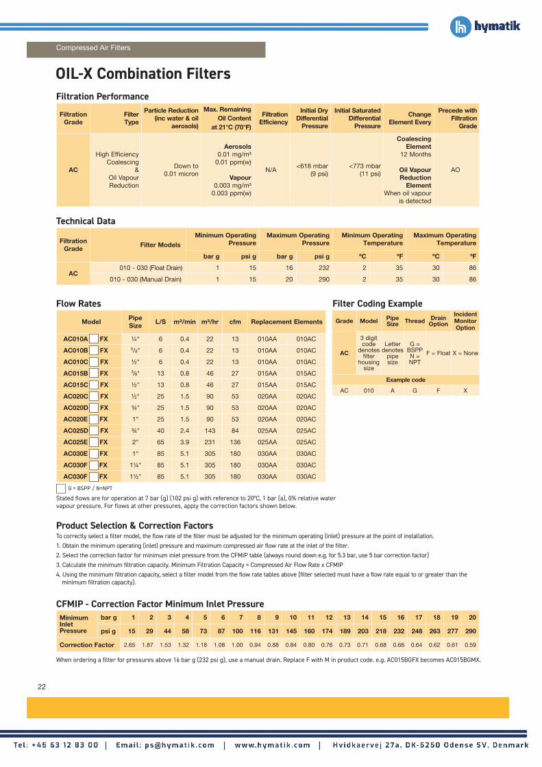
Flow Rates
Filtration Grade
Filter Type
Particle Reduction (inc water & oil
aerosols)
Max. Remaining Oil Content
at 21°C (70°F)
Filtration Efficiency
Initial Dry Differential
Pressure
Initial Saturated Differential
Pressure
Change Element Every
Precede with Filtration
Grade
AC
High Efficiency Coalescing
& Oil Vapour Reduction
Down to 0.01 micron
Aerosols0.01 mg/m³
0.01 ppm(w)
Vapour0.003 mg/m³
0.003 ppm(w)
N/A<618 mbar
(9 psi)<773 mbar
(11 psi)
Coalescing Element
12 Months
Oil Vapour Reduction
ElementWhen oil vapour
is detected
AO
Filtration Grade
Filter ModelsMinimum Operating
PressureMaximum Operating
PressureMinimum Operating
TemperatureMaximum Operating
Temperature
bar g psi g bar g psi g ºC ºF ºC ºF
AC010 - 030 (Float Drain) 1 15 16 232 2 35 30 86
010 - 030 (Manual Drain) 1 15 20 290 2 35 30 86
To correctly select a filter model, the flow rate of the filter must be adjusted for the minimum operating (inlet) pressure at the point of installation.1. Obtain the minimum operating (inlet) pressure and maximum compressed air flow rate at the inlet of the filter.2. Select the correction factor for minimum inlet pressure from the CFMIP table (always round down e.g. for 5.3 bar, use 5 bar correction factor)3. Calculate the minimum filtration capacity. Minimum Filtration Capacity = Compressed Air Flow Rate x CFMIP 4. Using the minimum filtration capacity, select a filter model from the flow rate tables above (filter selected must have a flow rate equal to or greater than the
minimum filtration capacity).
MinimumInlet Pressure
bar g 1 2 3 4 5 6 7 8 9 10 11 12 13 14 15 16 17 18 19 20
psi g 15 29 44 58 73 87 100 116 131 145 160 174 189 203 218 232 248 263 277 290
Correction Factor 2.65 1.87 1.53 1.32 1.18 1.08 1.00 0.94 0.88 0.84 0.80 0.76 0.73 0.71 0.68 0.66 0.64 0.62 0.61 0.59
Stated flows are for operation at 7 bar (g) (102 psi g) with reference to 20°C, 1 bar (a), 0% relative water vapour pressure. For flows at other pressures, apply the correction factors shown below.
Filtration Performance
Technical Data
Product Selection & Correction Factors
Filter Coding Example
Grade Model Pipe Size Thread Drain
Option
Incident Monitor Option
AC
3 digit code
denotes filter
housing size
Letter denotes
pipe size
G = BSPPN = NPT
F = Float X = None
Example code
AC 010 A G F X
ModelPipe Size
L/S m³/min m³/hr cfm Replacement Elements
AC010A FX 1/4" 6 0.4 22 13 010AA 010AC
AC010B FX 3/8" 6 0.4 22 13 010AA 010AC
AC010C FX 1/2" 6 0.4 22 13 010AA 010AC
AC015B FX 3/8" 13 0.8 46 27 015AA 015AC
AC015C FX 1/2" 13 0.8 46 27 015AA 015AC
AC020C FX 1/2" 25 1.5 90 53 020AA 020AC
AC020D FX 3/4" 25 1.5 90 53 020AA 020AC
AC020E FX 1" 25 1.5 90 53 020AA 020AC
AC025D FX 3/4" 40 2.4 143 84 025AA 025AC
AC025E FX 2" 65 3.9 231 136 025AA 025AC
AC030E FX 1" 85 5.1 305 180 030AA 030AC
AC030F FX 11/4" 85 5.1 305 180 030AA 030AC
AC030F FX 11/2" 85 5.1 305 180 030AA 030AC
G = BSPP / N=NPT
When ordering a filter for pressures above 16 bar g (232 psi g), use a manual drain. Replace F with M in product code. e.g. AC015BGFX becomes AC015BGMX.
OIL-X Combination Filters
Compressed Air Filters
CFMIP - Correction Factor Minimum Inlet Pressure
23
www.parker.com/gsfe
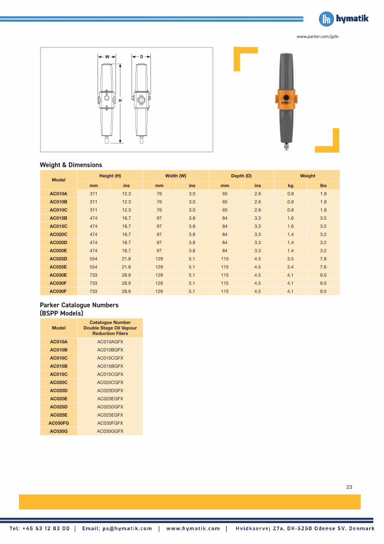
ModelHeight (H) Width (W) Depth (D) Weight
mm ins mm ins mm ins kg lbs
AC010A 311 12.3 76 3.0 65 2.6 0.8 1.8
AC010B 311 12.3 76 3.0 65 2.6 0.8 1.8
AC010C 311 12.3 76 3.0 65 2.6 0.8 1.8
AC015B 474 18.7 97 3.8 84 3.3 1.6 3.5
AC015C 474 18.7 97 3.8 84 3.3 1.6 3.5
AC020C 474 18.7 97 3.8 84 3.3 1.4 3.2
AC020D 474 18.7 97 3.8 84 3.3 1.4 3.2
AC020E 474 18.7 97 3.8 84 3.3 1.4 3.2
AC025D 554 21.8 129 5.1 115 4.5 3.5 7.8
AC025E 554 21.8 129 5.1 115 4.5 3.4 7.6
AC030E 733 28.9 129 5.1 115 4.5 4.1 9.0
AC030F 733 28.9 129 5.1 115 4.5 4.1 9.0
AC030F 733 28.9 129 5.1 115 4.5 4.1 9.0
Weight & Dimensions
ModelCatalogue Number
Double Stage Oil Vapour Reduction Filers
AC010A AC010AGFX
AC010B AC010BGFX
AC010C AC010CGFX
AC015B AC015BGFX
AC015C AC015CGFX
AC020C AC020CGFX
AC020D AC020DGFX
AC020E AC020EGFX
AC025D AC025DGFX
AC025E AC025EGFX
AC030FG AC030FGFX
AC030G AC030GGFX
W
H
D
Parker Catalogue Numbers (BSPP Models)

24
Compressed Air Filters
Hyperfilter Die-cast Aluminium Filters
Flow Rates
Filtration Grade
Filter Type
Particle Reduction (inc water & oil
aerosols)
Max. Remaining Oil Content
at 21°C (70°F)
Filtration Efficiency
Initial Dry Differential
Pressure
Initial Saturated Differential
Pressure
Change Element Every
Precede with Filtration
Grade
QCoalescing & Dry
ParticulateDown to 3 micron N/A N/A
<70 mbar (<1 psi)
<140 mbar (<2 psi)
12 monthsWS (for bulk
liquid)
PCoalescing & Dry
ParticulateDown to 1 micron
0.6 mg/m³ 0.5 ppm(w)
99.9%<70 mbar
(<1 psi)<140 mbar
(<2 psi)12 months Q
SCoalescing & Dry
ParticulateDown to 0.01
micron0.01 mg/m³
0.01 ppm(w)99.9999%
<100 mbar (<1.45 psi)
<200 mbar (<3 psi)
12 months P
DDry Particulate downstream of
adsorption dryerDown to 3 micron N/A 99.9%
<70 mbar (<1 psi)
N/A 12 months -
C Adsorption N/A0.003 mg/m³
0.003 ppm(w) of Oil Vapour
N/A<350 mbar
(<5 psi)N/A
When oil vapour is detected
P+S
Filtration Grade
Filter ModelsMinimum Operating
PressureMaximum Operating
PressureMinimum Operating
TemperatureMaximum Operating
Temperature
bar g psi g bar g psi g ºC ºF ºC ºFQ/P/S/D HFN005 - HFN370 1 15 16 232 2 35 65 149
C HFN005 - HFN370 1 15 16 232 2 35 50 122
To correctly select a filter model, the flow rate of the filter must be adjusted for the minimum operating (inlet) pressure at the point of installation.1. Obtain the minimum operating (inlet) pressure and maximum compressed air flow rate at the inlet of the filter.2. Select the correction factor for minimum inlet pressure from the CFMIP table (always round down e.g. for 5.3 bar, use 5 bar correction factor)3. Calculate the minimum filtration capacity. Minimum Filtration Capacity = Compressed Air Flow Rate x CFMIP 4. Using the minimum filtration capacity, select a filter model from the flow rate tables above (filter selected must have a flow rate equal to or greater than the
minimum filtration capacity).
MinimumInlet Pressure
bar g 1 2 3 4 5 6 7 8 9 10 11 12 13 14 15 16
psi g 15 29 44 58 73 87 100 116 131 145 160 174 189 203 218 232
Correction Factor 2.65 1.87 1.53 1.32 1.18 1.08 1.00 0.94 0.88 0.84 0.80 0.76 0.73 0.71 0.68 0.66
Stated flows are for operation at 7 bar (g) (102 psi g) with reference to 20°C, 1 bar (a), 0% relative water vapour pressure. For flows at other pressures, apply the correction factors shown below.
Filtration Performance
Technical Data
Product Selection & Correction Factors
Filter Coding Example
Grade Part Number
Q HFN018QWD
P HFN018PWD
S HFN018SWD
D HFN018DWD
C HFN018CWD
ModelPipe Size
L/S m³/min m³/hr cfmReplacement
ElementNo.
HFN005 WD 1/4" 8.8 0.5 31.8 18 005-ELZ 1
HFN010 WD 3/8" 16.7 1.0 60 35 010-ELZ 1
HFN018 WD 1/2" 30.0 1.8 108 63 018-ELZ 1
HFN022 WD 1/2" 36.7 2.2 132 77 022-ELZ 1
HFN030 WD 1/2" 50.0 3.0 180 106 030-ELZ 1
HFN045 WD 3/4" 75.0 4.5 270 159 045-ELZ 1
HFN062 WD 3/4” 103.3 6.2 372 219 062-ELZ 1
HFN072 WD 1" 120.0 7.2 432 254 072-ELZ 1
HFN122 WD 11/2" 203.3 12.2 732 430 122-ELZ 1
HFN135 WD 11/2" 225.0 13.5 810 477 135-ELZ 1
HFN175 WD 2" 291.7 17.5 1050 618 175-ELZ 1
HFN205 WD 21/2" 341.7 20.5 1230 724 205-ELZ 1
HFN300 WD 21/2" 500.0 30.0 1800 1059 300-ELZ 1
HFN370 WD 3" 611.1 37.0 2220 1295.0 370-ELZ 1
Grade
Grade
Grade
Grade
Grade
Grade
Grade
Grade
Grade
Grade
Grade
Grade
Grade
Grade
Grade
Grade
Grade
Grade
Grade
Grade
Grade
Grade
Grade
Grade
Grade
Grade
Grade
Grade
CFMIP - Correction Factor Minimum Inlet Pressure

25
www.parker.com/gsfe
ModelHeight (H) Width (W) Weight
mm ins mm ins kg lbs
HFN005 168 6.6 69 2.7 0.6 1.3
HFN010 267 10.5 89 3.5 1.2 2.6
HFN018 267 10.5 89 3.5 1.2 2.6
HFN022 267 10.5 89 3.5 1.2 2.6
HFN030 367 14.4 109 4.3 2.4 5.3
HFN045 367 14.4 109 4.3 2.4 5.3
HFN062 514 20.2 109 4.3 3.0 6.6
HFN072 514 20.2 109 4.3 3.0 6.6
HFN122 550 21.6 150 5.9 5.2 11.5
HFN135 550 21.6 150 5.9 5.2 11.5
HFN175 928 36.5 150 5.9 6.5 14.3
HFN205 928 36.5 150 5.9 6.6 14.5
HFN300 733 28.8 188 7.4 13.5 29.8
HFN370 933 36.7 188 7.4 16.0 35.3
Weight & Dimensions
Filtration Grade Q P S D C
Filter TypeCoalescing &
Dry ParticulateCoalescing &
Dry ParticulateCoalescing &
Dry ParticulateDry Particulate Adsorption
Test Methods Used ISO8573-2 ISO8573-2 ISO8573-2 N/A N/A
ISO12500-1 Inlet Challenge Concentration
N/ANot Tested to ISO 12500-1
N/ANot Tested to ISO 12500-1
N/ANot Tested to ISO 12500-1
N/A N/A
Filtration Tested In Accordance With
HFN005-205 HFN300-370
W
H
H
W

26
Flow Rates
Filtration Grade
Filter Type
Particle Reduction (inc water & oil
aerosols)
Max Remaining Oil Content
at 21°C (70°F)
Filtration Efficiency
Initial Dry Differential
Pressure
Initial Saturated Differential
Pressure
Change Element
Every
Precede with Filtration
Grade
AOCoalescing &
Dry ParticulateDown to 1 micron
0.5 mg/m³ 0.5 ppm(w)
99.925%<70 mbar
(<1 psi)<140 mbar
(<2 psi)12 months -
AACoalescing &
Dry ParticulateDown to 0.01
micron0.01 mg/m³
0.01 ppm(w)99.9999%
<140 mbar (<1.5 psi)
<200 mbar (<3 psi)
12 months AO
ACSOil Vapour Reduction
N/A0.003 mg/m³
0.003 ppm(w)N/A
<140 mbar (<1.5 psi)
N/AWhen oil vapour is detected
AO+AA
Filtration Grade
Filter ModelsMinimum Operating
PressureMaximum Operating
PressureMinimum Operating
TemperatureMaximum Operating
Temperature
bar g psi g bar g psi g ºC ºF ºC ºF
AO/AA 0003G 1 14.5 10 145 2 35 50 122
ACS 0003G 1 14.5 10 145 2 35 30 86
To correctly select a filter model, the flow rate of the filter must be adjusted for the minimum operating (inlet) pressure at the point of installation.1. Obtain the minimum operating (inlet) pressure and maximum compressed air flow rate at the inlet of the filter.2. Select the correction factor for minimum inlet pressure from the CFMIP table (always round down e.g. for 5.3 bar, use 5 bar correction factor)3. Calculate the minimum filtration capacity. Minimum Filtration Capacity = Compressed Air Flow Rate x CFP 4. Using the minimum filtration capacity, select a filter model from the flow rate tables above (filter selected must have a flow rate equal to or greater than the
minimum filtration capacity).
MinimumInlet Pressure
bar g 1 2 3 4 5 6 7 8 9 10
psi g 15 29 44 58 73 87 100 116 131 145
Correction Factor 2.65 1.87 1.53 1.32 1.18 1.08 1.00 0.94 0.88 0.84
All models include a manual / constant bleed drain
Stated flows are for operation at 7 bar (g) (102 psi g) with reference to 20°C, 1 bar (a), 0% relative water vapour pressure. For flows at other pressures, apply the correction factors shown below.
Filtration Performance
Technical Data
Product Selection & Correction Factors
ModelPipe Size
L/S m³/min m³/hr cfm Replacement Element No.
AO-0003G 8mm Push In 3 0.18 11 6 K003AO 1
AA-0003G 8mm Push In 3 0.18 11 6 K003AA 1
ACS-0003G 8mm Push In 3 0.18 11 6 K003ACS 1
Important Note:Using the same filter housings as their coalescing and dry particulate counterparts, Grade ACS filter elements differ in that they utilise a wrapped bed of carbon cloth to adsorb oil vapour. It is important to note, in-line adsorption filter elements have a different life span compared to coalescing and dry particulate filters and require more frequent element changes.
0003G Micro Filters
Compressed Air Filters
CFMIP - Correction Factor Minimum Inlet Pressure

27
www.parker.com/gsfe
ModelHeight (H) Width (W) Depth (D) Weight
mm ins mm ins mm ins kg lbs
0003G 89 3.5 58 2.3 56 2.2 0.1 0.2
Weight & Dimensions
ModelCatalogue NumberGeneral Purpose
Coalescing Filters
Catalogue NumberGeneral Purpose
Dry Particulate Filters
0003G AO-0003G AA-0003G
OIL-X Filter Accessories
Parker Catalogue Numbers
Filter Wall Mount Brackets (for 2 or 3 in series)
Filter Wall Mount Brackets (for single filters) Automatic Float and Manual Drains
Zero Loss ED Electronic Drains
Part Number Filter Model / Number of
MBK1-1 010 x 1
MBK2-1 015-020 x 1
MBK3-1 025-030 x 1
MBK4-1 035-045 x 1
MBK5-1 050-055 x 1
Unless stated otherwise all differential pressure monitors, gauges and drains have a maximum operating pressure of 16 bar g.
Part Number Description
PD15NO Float Auto 010-055
EM1Manual Drain 010-055 (Maximum Operating Pressure 20 bar g)
HDF120A Float Auto 060
605006470 Manual Drain 060
Part Number Filter Model / Number of
MBK1-2 010 x 2 and x 3
MBK2-2 015-020 x 2 and x 3
MBK3-2 025 - 030 x 2 and x 3
MBK4-2 035 - 045 x 2 and x 3
MBK5-2 050 - 055 x 2 and x 3
Part Number Filter Model
ED3002-G230 010 to 030
ED3004-G230 035 to 055
ED3007-G230 60
MK-G15-G10I ED3002 Mounting kit G1/2
MK-G25-G15 ED3004-3100 Mounting kit G1/2
H
W

28
ModelPipe Size
BSPP or NPT
Inlet Flow Rate
L/s m3/min m3/hr cfm
K-MT 1 G1/4 2 0.13 8 5
K-MT 2 G1/4 4 0.25 15 9
K-MT 3 G1/4 7 0.42 25 15
K-MT 4 G1/4 10 0.58 35 21
Dryer Models
Minimum Operating Pressure
Maximum Operating Pressure
Minimum Operating
Temperature
Maximum Operating
Temperature
Maximum Ambient
Temperature
Electrical Supply
(Standard)
Electrical Supply
(Optional)
Thread Type
Noise Level
bar g psi g bar g psi g °C °F °C °F °C °F dB(A)
K-MT 1 - 4 5 73 16 232 5 41 50 122 50 122230V 1ph50/60Hz
115V 1ph50/60Hz
BSPP 65-86
Outlet Dewpoint°C -20 -40 -70
°F -4 -40 -100
Correction Factor 1.00 1.00 2.00
Maximum Inlet Temperature
°C 25 30 35 40 45 50
°F 77 86 95 104 113 122
Correction Factor 0.94 0.95 1.00 1.15 1.22 1.28
Maximum Ambient Temperature
°C 25 30 35 40 45 50
°F 77 86 95 104 113 122
Correction Factor 1.00 1.00 1.00 1.00 1.00 1.00
Minimum Inlet Pressure
bar g 5 6 7 8 9 10 11 12 13 14 15 16
psi g 73 87 100 116 131 145 160 174 189 203 218 232
Correction Factor 1.33 1.12 1.00 0.88 0.79 0.76 0.74 0.67 0.62 0.59 0.56 0.53
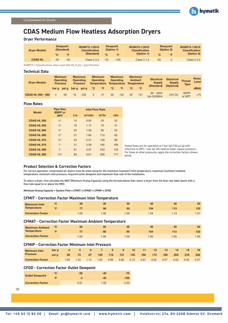
Product Selection & Correction FactorsFor correct operation, compressed air dryers must be sized using for the maximum (summer) inlet temperature, maximum (summer) ambient temperature, minimum inlet pressure, required outlet dewpoint and maximum flow rate of the installation.
To select a dryer, first calculate the MDC (Minimum Drying Capacity) using the formula below then select a dryer from the flow rate table above with a flow rate equal to or above the MDC. Minimum Drying Capacity = System Flow x CFMIT x CFMAT x CFMIP x CFOD
ISO8573-1 Classifications when used with OIL-X pre / post filtration
Dryer ModelsDewpoint (Standard)
ISO8573-1:2010 Classification
(Standard)
Dewpoint (Option 1)
ISO8573-1:2010 Classification
(Option 1)
Dewpoint (Option 2)
ISO8573-1:2010 Classification
(Option 2)°C °F °C °F °C °F
K-MT 1 - 4 -40 -40 Class 2.2.2 -70 -100 Class 2.1.2 -20 -4 Class 2.3.2
K-MT Small Flow Heatless Adsorption Dryers
Compressed Air Dryers
Technical Data
Flow Rates
CFMIT - Correction Factor Maximum Inlet Temperature
CFMAT - Correction Factor Maximum Ambient Temperature
CFMIP - Correction Factor Minimum Inlet Pressure
CFOD - Correction Factor Outlet Dewpoint
Dryer Performance
Stated flows are for operation at 7 bar (g) (102 psi g) with reference to 20°C, 1 bar (a), 0% relative water vapour pressure. For flows at other pressures, apply the correction factors shown below.

29
www.parker.com/gsfe
Maximum Ambient Temperature
°C 25 30 35 40 45 50
°F 77 86 95 104 113 122
Correction Factor 1.00 1.00 1.00 1.00 1.00 1.00
ModelPipe Size
BSPP or NPT
Dryer Inlet Dryer Inlet Dryer Outlet
General Purpose Pre-filter
High Efficiency Filter
Oil Vapour Reduction Filter
General Purpose Dry Particulate
Filter
High Efficiency Dry Particulate
Filter
K-MT 1 1/4" AOP010A AAP010A - AOP010A -
K-MT 2 1/4" AOP010A AAP010A - AOP010A -
K-MT 3 1/4" AOP010A AAP010A - AOP010A -
K-MT 4 1/4" AOP010A AAP010A - AOP010A -
Model
DimensionsWeightHeight (H) Width (W) Depth (D)
mm ins mm ins mm ins kg lbs
K-MT 1 400 15.75 326 12.86 216 8.5 11.5 25.35
K-MT 2 575 22.65 326 12.86 216 8.5 15.5 34.20
K-MT 3 825 32.5 326 12.86 216 8.5 20.0 44.10
K-MT 4 1075 42.35 326 12.86 216 8.5 25.0 55.10
For Dryer Model
Catalogue NumberNo Dewpoint Sensor
Catalogue NumberWith Dewpoint Sensor
K-MT 1 K1/16D3-G230M K1/16D3-G230MT
K-MT 2 K2/16D3-G230M K2/16D3-G230MT
K-MT 3 K3/16D3-G230M K3/16D3-G230MT
K-MT 4 K4/16D3-G230M K4/16D3-G230MT
Weights & Dimensions
Required Filtration Included Filtration
Parker Catalogue Numbers230V/1ph/50Hz-60Hz
W
H
D

30
ModelPipe SizeBSPP or
NPT
Inlet Flow Rate
L/s m3/min m3/hr cfm
KA-MT 1 G1/4 2 0.13 8 5
KA-MT 2 G1/4 4 0.25 15 9
KA-MT 3 G1/4 7 0.42 25 15
KA-MT 4 G1/4 10 0.58 35 21
Dryer Models
Minimum Operating Pressure
Maximum Operating Pressure
Minimum Operating
Temperature
Maximum Operating
Temperature
Maximum Ambient
Temperature
Electrical Supply
(Standard)
Electrical Supply
(Optional)
Thread Type
Noise Level
bar g psi g bar g psi g °C °F °C °F °C °F dB(A)
KA-MT 1 - 4 5 73 16 232 5 41 50 122 50 122230V 1ph50/60Hz
115V 1ph50/60Hz
BSPP 65-86
Outlet Dewpoint°C -20 -40 -70
°F -4 -40 -100
Correction Factor 1.00 1.00 2.00
Maximum Inlet Temperature
°C 25 30 35 40 45 50
°F 77 86 95 104 113 122
Correction Factor 0.94 0.95 1.00 1.15 1.22 1.28
Maximum Ambient Temperature
°C 25 30 35 40 45 50
°F 77 86 95 104 113 122
Correction Factor 1.00 1.00 1.00 1.00 1.00 1.00
Minimum Inlet Pressure
bar g 5 6 7 8 9 10 11 12 13 14 15 16
psi g 73 87 100 116 131 145 160 174 189 203 218 232
Correction Factor 1.33 1.12 1.00 0.88 0.79 0.76 0.74 0.67 0.62 0.59 0.56 0.53
Product Selection & Correction FactorsFor correct operation, compressed air dryers must be sized using for the maximum (summer) inlet temperature, maximum (summer) ambient temperature, minimum inlet pressure, required outlet dewpoint and maximum flow rate of the installation.
To select a dryer, first calculate the MDC (Minimum Drying Capacity) using the formula below then select a dryer from the flow rate table above with a flow rate equal to or above the MDC. Minimum Drying Capacity = System Flow x CFMIT x CFMAT x CFMIP x CFOD
ISO8573-1 Classifications when used with OIL-X pre / post filtration
Dryer ModelsDewpoint (Standard)
ISO8573-1:2010 Classification
(Standard)
Dewpoint (Option 1)
ISO8573-1:2010 Classification
(Option 1)
Dewpoint (Option 2)
ISO8573-1:2010 Classification
(Option 2)°C °F °C °F °C °F
KA-MT 1 - 4 -40 -40 Class 2.2.2 -70 -100 Class 2.1.2 -20 -4 Class 2.3.2
KA-MT Small Flow Heatless Adsorption Dryers
Compressed Air Dryers
Dryer Performance
Technical Data
Flow Rates
CFMIT - Correction Factor Maximum Inlet Temperature
CFMAT - Correction Factor Maximum Ambient Temperature
CFMIP - Correction Factor Minimum Inlet Pressure
CFOD - Correction Factor Outlet Dewpoint
Stated flows are for operation at 7 bar (g) (102 psi g) with reference to 20°C, 1 bar (a), 0% relative water vapour pressure. For flows at other pressures, apply the correction factors shown below.

31
www.parker.com/gsfe
Maximum Ambient Temperature
°C 25 30 35 40 45 50
°F 77 86 95 104 113 122
Correction Factor 1.00 1.00 1.00 1.00 1.00 1.00
Model
DimensionsWeightHeight (H) Width (W) Depth (D)
mm ins mm ins mm ins kg lbs
KA-MT 1 400 15.75 459 18.1 216 8.5 15 33
KA-MT 2 575 22.65 459 18.1 216 8.5 20 44
KA-MT 3 825 32.5 459 18.1 216 8.5 28 62
KA-MT 4 1075 42.35 459 18.1 216 8.5 35 77
ModelPipe Size
BSPP or NPT
Dryer Inlet Dryer Inlet Dryer Outlet
General Purpose Pre-filter
High Efficiency Filter
Oil Vapour Reduction Filter
General Purpose Dry Particulate
Filter
High Efficiency Dry Particulate
Filter
KA-MT 1 1/4" AOP010A AAP010A - AOP010A -
KA-MT 2 1/4" AOP010A AAP010A - AOP010A -
KA-MT 3 1/4" AOP010A AAP010A - AOP010A -
KA-MT 4 1/4" AOP010A AAP010A - AOP010A -
Parker Catalogue Numbers230V/1ph/50Hz-60Hz
Included FiltrationRequired Filtration
Weights & Dimensions
W
H
D
For Dryer Model
Catalogue NumberNo Dewpoint Sensor
Catalogue NumberWith Dewpoint Sensor
KA-MT 1 K1/16DA3-G230M K1/16DA3-G230MT
KA-MT 2 K2/16DA3-G230M K2/16DA3-G230MT
KA-MT 3 K3/16DA3-G230M K3/16DA3-G230MT
KA-MT 4 K4/16DA3-G230M K4/16DA3-G230MT
32
ModelPipe SizeBSPP or
NPT
Inlet Flow Rate
L/s m3/min m3/hr cfm
CDAS HL 050 1/2" 15 0.92 55 32
CDAS HL 055 1/2" 19 1.17 70 41
CDAS HL 060 1/2" 25 1.50 90 53
CDAS HL 065 1/2" 31 1.84 110 65
CDAS HL 070 3/4" 42 2.51 150 88
CDAS HL 075 1" 51 3.09 185 109
CDAS HL 080 1" 61 3.67 220 129
CDAS HL 085 11/2" 83 5.01 300 177
Dryer ModelsDewpoint (Standard)
ISO8573-1:2010 Classification
(Standard)
Dewpoint (Option 1)
ISO8573-1:2010 Classification
(Option 1)
Dewpoint (Option 2)
ISO8573-1:2010 Classification
(Option 2)°C °F °C °F °C °F
CDAS HL -40 -40 Class 2.2.2 -70 -100 Class 2.1.2 -20 -4 Class 2.3.2
Dryer Models
Minimum Operating Pressure
Maximum Operating Pressure
Minimum Operating
Temperature
Maximum Operating
Temperature
Maximum Ambient
Temperature
Electrical Supply
(Standard)
Electrical Supply
(Optional)
Thread Type
Noise Level
bar g psi g bar g psi g °C °F °C °F °C °F dB(A)
CDAS HL 050 - 085 4 58 16 232 5 41 50 122 55 13185 - 265V
1ph 50/60Hz24V DC
BSPP or NPT
<75
Outlet Dewpoint°C -20 -40 -70
°F -4 -40 -100
Correction Factor 0.91 1.00 2.00
Maximum Inlet Temperature
°C 25 30 35 40 45 50
°F 77 86 95 104 113 122
Correction Factor 1.00 1.00 1.00 1.04 1.14 1.37
Maximum Ambient Temperature
°C 25 30 35 40 45 50
°F 77 86 95 104 113 122
Correction Factor 1.00 1.00 1.00 1.00 1.00 1.00
Minimum Inlet Pressure
bar g 4 5 6 7 8 9 10 11 12 13 14 15 16
psi g 58 73 87 100 116 131 145 160 174 189 203 218 232
Correction Factor 1.60 1.33 1.14 1.00 0.89 0.80 0.73 0.67 0.62 0.57 0.53 0.50 0.47
Product Selection & Correction FactorsFor correct operation, compressed air dryers must be sized using for the maximum (summer) inlet temperature, maximum (summer) ambient temperature, minimum inlet pressure, required outlet dewpoint and maximum flow rate of the installation.
To select a dryer, first calculate the MDC (Minimum Drying Capacity) using the formula below then select a dryer from the flow rate table above with a flow rate equal to or above the MDC. Minimum Drying Capacity = System Flow x CFMIT x CFMAT x CFMIP x CFOD
CDAS Medium Flow Heatless Adsorption Dryers
Compressed Air Dryers
Dryer Performance
Technical Data
Flow Rates
ISO8573-1 Classifications when used with OIL-X pre / post filtration
Stated flows are for operation at 7 bar (g) (102 psi g) with reference to 20°C, 1 bar (a), 0% relative water vapour pressure. For flows at other pressures, apply the correction factors shown below.
CFMIT - Correction Factor Maximum Inlet Temperature
CFMAT - Correction Factor Maximum Ambient Temperature
CFMIP - Correction Factor Minimum Inlet Pressure
CFOD - Correction Factor Outlet Dewpoint
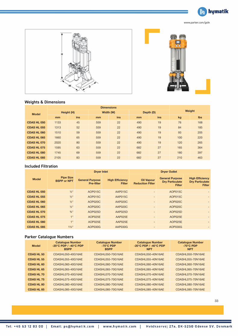
33
www.parker.com/gsfe
Maximum Ambient Temperature
°C 25 30 35 40 45 50
°F 77 86 95 104 113 122
Correction Factor 1.00 1.00 1.00 1.00 1.00 1.00
ModelPipe Size
BSPP or NPT
Dryer Inlet Dryer Outlet
General PurposePre-filter
High Efficiency Filter
Oil Vapour Reduction Filter
General Purpose Dry Particulate
Filter
High Efficiency Dry Particulate
Filter
CDAS HL 050 1/2 " AOP015C AAP015C - AOP015C -
CDAS HL 055 1/2 " AOP015C AAP015C - AOP015C -
CDAS HL 060 1/2 " AOP020C AAP020C - AOP020C -
CDAS HL 065 1/2 " AOP020C AAP020C - AOP020C -
CDAS HL 070 3/4 " AOP025D AAP025D - AOP025D -
CDAS HL 075 1" AOP025E AAP025E - AOP025E -
CDAS HL 080 1" AOP025E AAP025E - AOP025E -
CDAS HL 085 11/2 " AOP030G AAP030G - AOP030G -
Model
DimensionsWeightHeight (H) Width (W) Depth (D)
mm ins mm ins mm ins kg lbs
CDAS HL 050 1133 45 559 22 490 19 76 168
CDAS HL 055 1313 52 559 22 490 19 84 185
CDAS HL 060 1510 59 559 22 490 19 93 205
CDAS HL 065 1660 65 559 22 490 19 100 220
CDAS HL 070 2020 80 559 22 490 19 120 265
CDAS HL 075 1595 63 559 22 682 27 165 364
CDAS HL 080 1745 69 559 22 682 27 180 397
CDAS HL 085 2105 83 559 22 682 27 210 463
Model Catalogue Number
-20°C PDP / -40°C PDPBSPP
Catalogue Number-70°C PDP
BSPP
Catalogue Number-20°C PDP / -40°C PDP
NPT
Catalogue Number-70°C PDP
NPT
CDAS HL 50 CDASHL050-40G16AE CDASHL050-70G16AE CDASHL050-40N16AE CDASHL050-70N16AE
CDAS HL 55 CDASHL055-40G16AE CDASHL055-70G16AE CDASHL055-40N16AE CDASHL055-70N16AE
CDAS HL 60 CDASHL060-40G16AE CDASHL060-70G16AE CDASHL060-40N16AE CDASHL060-70N16AE
CDAS HL 65 CDASHL065-40G16AE CDASHL065-70G16AE CDASHL065-40N16AE CDASHL065-70N16AE
CDAS HL 70 CDASHL070-40G16AE CDASHL070-70G16AE CDASHL070-40N16AE CDASHL070-70N16AE
CDAS HL 75 CDASHL075-40G16AE CDASHL075-70G16AE CDASHL075-40N16AE CDASHL075-70N16AE
CDAS HL 80 CDASHL080-40G16AE CDASHL080-70G16AE CDASHL080-40N16AE CDASHL080-70N16AE
CDAS HL 85 CDASHL085-40G16AE CDASHL085-70G16AE CDASHL085-40N16AE CDASHL085-70N16AE
Weights & Dimensions
Included Filtration
Parker Catalogue Numbers
W
H
D

34
ModelPipe Size
BSPP or NPT
Inlet Flow Rate
L/s m3/min m3/hr cfm
OFAS HL 050 1/2" 15 0.92 55 32
OFAS HL 055 1/2" 19 1.17 70 41
OFAS HL 060 1/2" 25 1.50 90 53
OFAS HL 065 1/2" 31 1.84 110 65
OFAS HL 070 3/4" 42 2.51 150 88
OFAS HL 075 1" 51 3.09 185 109
OFAS HL 080 1" 61 3.67 220 129
OFAS HL 085 11/2" 83 5.01 300 177
Dryer ModelsDewpoint (Standard)
ISO8573-1:2010 Classification
(Standard)
Dewpoint (Option 1)
ISO8573-1:2010 Classification
(Option 1)
Dewpoint (Option 2)
ISO8573-1:2010 Classification
(Option 2)°C °F °C °F °C °F
OFAS HL -40 -40 Class 2.2.0 -70 -100 Class 2.1.0 -20 -4 Class 2.3.0
Dryer Models
Minimum Operating Pressure
Maximum Operating Pressure
Minimum Operating
Temperature
Maximum Operating
Temperature
Maximum Ambient
Temperature
Electrical Supply
(Standard)
Electrical Supply
(Optional)
Thread Type
Noise Level
bar g psi g bar g psi g °C °F °C °F °C °F dB(A)
OFAS HL 050 - 085 4 58 16 232 5 41 50 122 55 13185 - 265V
1ph 50/60Hz
24V DCBSPP or
NPT <75
Outlet Dewpoint°C -20 -40 -70
°F -4 -40 -100
Correction Factor 0.91 1.00 2.00
Maximum Inlet Temperature
°C 25 30 35 40 45 50
°F 77 86 95 104 113 122
Correction Factor 1.00 1.00 1.00 1.04 1.14 1.37
Maximum Ambient Temperature
°C 25 30 35 40 45 50
°F 77 86 95 104 113 122
Correction Factor 1.00 1.00 1.00 1.00 1.00 1.00
Minimum Inlet Pressure
bar g 4 5 6 7 8 9 10 11 12 13 14 15 16
psi g 58 73 87 100 116 131 145 160 174 189 203 218 232
Correction Factor 1.60 1.33 1.14 1.00 0.89 0.80 0.73 0.67 0.62 0.57 0.53 0.50 0.47
Product Selection & Correction FactorsFor correct operation, compressed air dryers must be sized using for the maximum (summer) inlet temperature, maximum (summer) ambient temperature, minimum inlet pressure, required outlet dewpoint and maximum flow rate of the installation.
To select a dryer, first calculate the MDC (Minimum Drying Capacity) using the formula below then select a dryer from the flow rate table above with a flow rate equal to or above the MDC. Minimum Drying Capacity = System Flow x CFMIT x CFMAT x CFMIP x CFOD
ISO8573-1 Classifications when used with OIL-X pre / post filtration
Stated flows are for operation at 7 bar (g) (102 psi g) with reference to 20°C, 1 bar (a), 0% relative water vapour pressure. For flows at other pressures, apply the correction factors shown below.
OFAS Medium Flow Heatless Adsorption Dryers
Compressed Air Dryers
Dryer Performance
Technical Data
Flow Rates
CFMIT - Correction Factor Maximum Inlet Temperature
CFMAT - Correction Factor Maximum Ambient Temperature
CFMIP - Correction Factor Minimum Inlet Pressure
CFOD - Correction Factor Outlet Dewpoint

35
www.parker.com/gsfe
ModelPipe Size
BSPP or NPT
Dryer Inlet Dryer Outlet
General Purpose Pre-filter
High Efficiency Filter
Oil Vapour Reduction Filter
General Purpose Dry Particulate
Filter
High Efficiency Dry Particulate
Filter
OFAS HL 050 1/2" AOP015C AAP015C Included AOP015C -
OFAS HL 055 1/2" AOP015C AAP015C Included AOP015C -
OFAS HL 060 1/2" AOP020C AAP020C Included AOP020C -
OFAS HL 065 1/2" AOP020C AAP020C Included AOP020C -
OFAS HL 070 3/4" AOP025D AAP025D Included AOP025D -
OFAS HL 075 1" AOP025E AAP025E Included AOP025E -
OFAS HL 080 1" AOP025E AAP025E Included AOP025E -
OFAS HL 085 11/2" AOP030G AAP030G Included AOP030G -
ModelDimensions
WeightHeight (H) Width (W) Depth (D)
mm ins mm ins mm ins kg lbs
OFAS HL 050 1133 45 559 22 512 20.2 90 198
OFAS HL 055 1313 52 559 22 512 20.2 97 214
OFAS HL 060 1510 59 559 22 496 19.5 106 234
OFAS HL 065 1660 65 559 22 496 19.5 112 247
OFAS HL 070 2020 80 559 22 496 19.5 132 291
OFAS HL 075 1595 63 559 22 682 27 184 406
OFAS HL 080 1745 69 559 22 682 27 196 432
OFAS HL 085 2105 83 559 22 682 27 232 511
Model Catalogue Number
-20°C PDP / -40°C PDPBSPP
Catalogue Number-70°C PDP
BSPP
Catalogue Number-20°C PDP / -40°C PDP
NPT
Catalogue Number-70°C PDP
NPT
OFAS HL 50 OFASHL050-40G16AE OFASHL050-70G16AE OFASHL050-40N16AE OFASHL050-70N16AE
OFAS HL 55 OFASHL055-40G16AE OFASHL055-70G16AE OFASHL055-40N16AE OFASHL055-70N16AE
OFAS HL 60 OFASHL060-40G16AE OFASHL060-70G16AE OFASHL060-40N16AE OFASHL060-70N16AE
OFAS HL 65 OFASHL065-40G16AE OFASHL065-70G16AE OFASHL065-40N16AE OFASHL065-70N16AE
OFAS HL 70 OFASHL070-40G16AE OFASHL070-70G16AE OFASHL070-40N16AE OFASHL070-70N16AE
OFAS HL 75 OFASHL075-40G16AE OFASHL075-70G16AE OFASHL075-40N16AE OFASHL075-70N16AE
OFAS HL 80 OFASHL080-40G16AE OFASHL080-70G16AE OFASHL080-40N16AE OFASHL080-70N16AE
OFAS HL 85 OFASHL085-40G16AE OFASHL085-70G16AE OFASHL085-40N16AE OFASHL085-70N16AE
Parker Catalogue Numbers
Included Filtration
Weights & Dimensions
W
H
D

36
ModelPipe SizeBSPP or
NPT
Inlet Flow Rate
L/s m3/min m3/hr cfm
FBP HL 050 1/2" 15 0.92 55 32
FBP HL 055 1/2" 19 1.17 70 41
FBP HL 060 1/2" 25 1.50 90 53
FBP HL 065 1/2" 31 1.84 110 65
FBP HL 070 3/4" 42 2.51 150 88
FBP HL 075 1" 51 3.09 185 109
FBP HL 080 1" 61 3.67 220 129
FBP HL 085 11/2" 83 5.01 300 177
Dryer ModelsDewpoint (Standard)
ISO8573-1:2010 Classification
(Standard)
Dewpoint (Option 1)
ISO8573-1:2010 Classification
(Option 1)
Dewpoint (Option 2)
ISO8573-1:2010 Classification
(Option 2)°C °F °C °F °C °F
FBP HL -40 -40 Class 2.2.0 -70 -100 Class 2.1.0 -20 -4 Class 2.3.0
Dryer Models
Minimum Operating Pressure
Maximum Operating Pressure
Minimum Operating
Temperature
Maximum Operating
Temperature
Maximum Ambient
Temperature
Electrical Supply
(Standard)
Electrical Supply
(Optional)
Thread Type
Noise Level
bar g psi g bar g psi g °C °F °C °F °C °F dB(A)
FBP HL 050 - 085 4 58 16 232 5 41 50 122 55 13185 - 265V
1ph 50/60Hz
24V DCBSPP or
NPT <75
Outlet Dewpoint°C -20 -40 -70
°F -4 -40 -100
Correction Factor 0.91 1.00 2.00
Maximum Inlet Temperature
°C 25 30 35 40 45 50
°F 77 86 95 104 113 122
Correction Factor 1.00 1.00 1.00 1.04 1.14 1.37
Maximum Ambient Temperature
°C 25 30 35 40 45 50
°F 77 86 95 104 113 122
Correction Factor 1.00 1.00 1.00 1.00 1.00 1.00
Minimum Inlet Pressure
bar g 4 5 6 7 8 9 10 11 12 13 14 15 16
psi g 58 73 87 100 116 131 145 160 174 189 203 218 232
Correction Factor 1.60 1.33 1.14 1.00 0.89 0.80 0.73 0.67 0.62 0.57 0.53 0.50 0.47
Product Selection & Correction FactorsFor correct operation, compressed air dryers must be sized using for the maximum (summer) inlet temperature, maximum (summer) ambient temperature, minimum inlet pressure, required outlet dewpoint and maximum flow rate of the installation.
To select a dryer, first calculate the MDC (Minimum Drying Capacity) using the formula below then select a dryer from the flow rate table above with a flow rate equal to or above the MDC. Minimum Drying Capacity = System Flow x CFMIT x CFMAT x CFMIP x CFOD
ISO8573-1 Classifications when used with OIL-X pre / post filtration
Stated flows are for operation at 7 bar (g) (102 psi g) with reference to 20°C, 1 bar (a), 0% relative water vapour pressure. For flows at other pressures, apply the correction factors shown below.
FBP Medium Flow Heatless Adsorption Dryers
Compressed Air Dryers
Dryer Performance
Technical Data
Flow Rates
CFMIT - Correction Factor Maximum Inlet Temperature
CFMAT - Correction Factor Maximum Ambient Temperature
CFMIP - Correction Factor Minimum Inlet Pressure
CFOD - Correction Factor Outlet Dewpoint

37
www.parker.com/gsfe
Maximum Ambient Temperature
°C 25 30 35 40 45 50
°F 77 86 95 104 113 122
Correction Factor 1.00 1.00 1.00 1.00 1.00 1.00
ModelPipe Size
BSPP or NPT
Dryer Inlet Dryer Outlet
General PurposePre-filter
High Efficiency Filter
Oil Vapour Reduction Filter
General Purpose Dry Particulate
Filter
High Efficiency Dry Particulate
Filter
FBP HL 050 1/2 " AOP015C AAP015C Included AOP015C AAP015C
FBP HL 055 1/2 " AOP015C AAP015C Included AOP015C AAP015C
FBP HL 060 1/2 " AOP020C AAP020C Included AOP020C AAP020C
FBP HL 065 1/2 " AOP020C AAP020C Included AOP020C AAP020C
FBP HL 070 3/4 " AOP025D AAP025D Included AOP025D AAP025D
FBP HL 075 1" AOP025E AAP025E Included AOP025E AAP025E
FBP HL 080 1" AOP025E AAP025E Included AOP025E AAP025E
FBP HL 085 11/2 " AOP030G AAP030G Included AOP030G AAP030G
ModelDimensions
WeightHeight (H) Width (W) Depth (D)
mm ins mm ins mm ins kg lbs
FBP HL 050 1133 45 559 22 512 20.2 90 198
FBP HL 055 1313 52 559 22 512 20.2 97 214
FBP HL 060 1510 59 559 22 496 19.5 106 234
FBP HL 065 1660 65 559 22 496 19.5 112 247
FBP HL 070 2020 80 630 24.8 496 19.5 132 291
FBP HL 075 1595 63 630 24.8 682 27 184 406
FBP HL 080 1745 69 630 24.8 682 27 196 432
FBP HL 085 2105 83 630 24.8 682 27 232 511
ModelCatalogue Number
-20°C PDP / -40°C PDPBSPP
Catalogue Number-70°C PDP
BSPP
FBP HL 050 FBPHL050-40G16AE FBPHL050-70G16AE
FBP HL 055 FBPHL055-40G16AE FBPHL055-70G16AE
FBP HL 060 FBPHL060-40G16AE FBPHL060-70G16AE
FBP HL 065 FBPHL065-40G16AE FBPHL065-70G16AE
FBP HL 070 FBPHL070-40G16AE FBPHL070-70G16AE
FBP HL 075 FBPHL075-40G16AE FBPHL075-70G16AE
FBP HL 080 FBPHL080-40G16AE FBPHL080-70G16AE
FBP HL 085 FBPHL085-40G16AE FBPHL085-70G16AE
Weights & Dimensions
Included Filtration
Parker Catalogue Numbers
W
H
D

38
ModelPipe SizeBSPP or
NPT
Inlet Flow Rate
L/s m3/min m3/hr cfm
CDAS HL 050 ATEX 1/2" 15 0.92 55 32
CDAS HL 055 ATEX 1/2" 19 1.17 70 41
CDAS HL 060 ATEX 1/2" 25 1.50 90 53
CDAS HL 065 ATEX 1/2" 31 1.84 110 65
CDAS HL 070 ATEX 3/4" 42 2.51 150 88
CDAS HL 075 ATEX 1" 51 3.09 185 109
CDAS HL 080 ATEX 1" 61 3.67 220 129
CDAS HL 085 ATEX 11/2" 83 5.01 300 177
Dryer ModelsDewpoint (Standard) ISO8573-1:2010
Classification (Standard)°C °F
CDAS HL ATEX -40 -40 Class 2.2.2
Dryer Models
Minimum Operating Pressure
Maximum Operating Pressure
Minimum Operating
Temperature
Maximum Operating
Temperature
Maximum Ambient
Temperature Electrical Supply Thread
Type
Noise Level
bar g psi g bar g psi g °C °F °C °F °C °F dB(A)
CDAS HL ATEX 4 58 16 232 5 41 50 122 55 131Not Applicable - Fully Pneumatic Operation
BSPP or NPT
<75
Outlet Dewpoint°C -20 -40 -70
°F -4 -40 -100
Correction Factor 0.91 1.00 2.00
Stated flows are for operation at 7 bar (g) (102 psi g) with reference to 20°C, 1 bar (a), 0% relative water vapour pressure. For flows at other pressures, apply the correction factors shown below.
Maximum Inlet Temperature
°C 25 30 35 40 45 50
°F 77 86 95 104 113 122
Correction Factor 1.00 1.00 1.00 1.04 1.14 1.37
Maximum Ambient Temperature
°C 25 30 35 40 45 50
°F 77 86 95 104 113 122
Correction Factor 1.00 1.00 1.00 1.00 1.00 1.00
Minimum Inlet Pressure
bar g 4 5 6 7 8 9 10 11 12 13 14 15 16
psi g 58 73 87 100 116 131 145 160 174 189 203 218 232
Correction Factor 1.60 1.33 1.14 1.00 0.89 0.80 0.73 0.67 0.62 0.57 0.53 0.50 0.47
Product Selection & Correction FactorsFor correct operation, compressed air dryers must be sized using for the maximum (summer) inlet temperature, maximum (summer) ambient temperature, minimum inlet pressure, required outlet dewpoint and maximum flow rate of the installation.
To select a dryer, first calculate the MDC (Minimum Drying Capacity) using the formula below then select a dryer from the flow rate table above with a flow rate equal to or above the MDC. Minimum Drying Capacity = System Flow x CFMIT x CFMAT x CFMIP x CFOD
ISO8573-1 Classifications when used with OIL-X pre / post filtration
CDAS HL ATEX Medium Flow Heatless Adsorption Dryers
Compressed Air Dryers
Dryer Performance
Technical Data
Flow Rates
CFMIT - Correction Factor Maximum Inlet Temperature
CFMAT - Correction Factor Maximum Ambient Temperature
CFMIP - Correction Factor Minimum Inlet Pressure
CFOD - Correction Factor Outlet Dewpoint

39
www.parker.com/gsfe
Maximum Ambient Temperature
°C 25 30 35 40 45 50
°F 77 86 95 104 113 122
Correction Factor 1.00 1.00 1.00 1.00 1.00 1.00
ModelPipe Size
BSPP or NPT
Dryer Inlet Dryer Outlet
General PurposePre-filter
High Efficiency Filter
Oil Vapour Reduction Filter
General Purpose Dry Particulate
Filter
High Efficiency Dry Particulate
Filter
CDAS HL 050 ATEX 1/2 " AOP015C AAP015C - AOP015C -
CDAS HL 055 ATEX 1/2 " AOP015C AAP015C - AOP015C -
CDAS HL 060 ATEX 1/2 " AOP020C AAP020C - AOP020C -
CDAS HL 065 ATEX 1/2 " AOP020C AAP020C - AOP020C -
CDAS HL 070 ATEX 3/4 " AOP025D AAP025D - AOP025D -
CDAS HL 075 ATEX 1" AOP025E AAP025E - AOP025E -
CDAS HL 080 ATEX 1" AOP025E AAP025E - AOP025E -
CDAS HL 085 ATEX 11/2 " AOP030G AAP030G - AOP030G -
ModelDimensions
WeightHeight (H) Width (W) Depth (D)
mm ins mm ins mm ins kg lbs
CDAS HL 050 ATEX 1133 45 559 22 490 19 76 168
CDAS HL 055 ATEX 1313 52 559 22 490 19 84 185
CDAS HL 060 ATEX 1510 59 559 22 490 19 93 205
CDAS HL 065 ATEX 1660 65 559 22 490 19 100 220
CDAS HL 070 ATEX 2020 80 559 22 490 19 120 265
CDAS HL 075 ATEX 1595 63 559 22 682 27 165 364
CDAS HL 080 ATEX 1745 69 559 22 682 27 180 397
CDAS HL 085 ATEX 2105 83 559 22 682 27 210 463
Model Catalogue Number
-20°C PDP / -40°C PDPBSPP
Catalogue Number-70°C PDP
BSPP
CDAS HL 050 ATEX CDASHL050-40G16PP CDASHL050-70G16PP
CDAS HL 055 ATEX CDASHL055-40G16PP CDASHL055-70G16PP
CDAS HL 060 ATEX CDASHL060-40G16PP CDASHL060-70G16PP
CDAS HL 065 ATEX CDASHL065-40G16PP CDASHL065-70G16PP
CDAS HL 070 ATEX CDASHL070-40G16PP CDASHL070-70G16PP
CDAS HL 075 ATEX CDASHL075-40G16PP CDASHL075-70G16PP
CDAS HL 080 ATEX CDASHL080-40G16PP CDASHL080-70G16PP
CDAS HL 085 ATEX CDASHL085-40G16PP CDASHL085-70G16PP
Weights & Dimensions
Included Filtration
Parker Catalogue Numbers
W
H
D

40
Dryer ModelsDewpoint (Standard)
ISO8573-1:2010 Classification
(Standard)
Dewpoint (Option 1)
ISO8573-1:2010 Classification
(Option 1)
Dewpoint (Option 2)
ISO8573-1:2010 Classification
(Option 2)°C °F °C °F °C °F
MXS DS -40 -40 Class 2.2.2 -70 -100 Class 2.1.2 -20 -4 Class 2.3.2
Dryer Models
Minimum Operating Pressure
Maximum Operating Pressure
Minimum Operating
Temperature
Maximum Operating
Temperature
Maximum Ambient
Temperature
Electrical Supply
(Standard)
Electrical Supply
(Optional)
Thread Type
Noise Level
bar g psi g bar g psi g °C °F °C °F °C °F dB(A)
MXS102CDS - MXS108DS
4 58 13 190 5 41 50 122 55 13185 - 265V
1ph 50/60Hz
N/ABSPP or
NPT <75
Outlet Dewpoint°C -20 -40 -70
°F -4 -40 -100
Correction Factor 0.91 1.00 1.43
Stated flows are for operation at 7 bar (g) (102 psi g) with reference to 20°C, 1 bar (a), 0% relative water vapour pressure. For flows at other pressures, apply the correction factors shown below.
Maximum Inlet Temperature
°C 25 30 35 40 45 50
°F 77 86 95 104 113 122
Correction Factor 1.00 1.00 1.00 1.04 1.14 1.37
Maximum Ambient Temperature
°C 25 30 35 40 45 50
°F 77 86 95 104 113 122
Correction Factor 1.00 1.00 1.00 1.00 1.00 1.00
Minimum Inlet Pressure
bar g 4 5 6 7 8 9 10 11 12 13
psi g 58 73 87 100 116 131 145 160 174 189
Correction Factor 1.60 1.33 1.14 1.00 0.89 0.80 0.73 0.67 0.62 0.57
Product Selection & Correction FactorsFor correct operation, compressed air dryers must be sized using for the maximum (summer) inlet temperature, maximum (summer) ambient temperature, minimum inlet pressure, required outlet dewpoint and maximum flow rate of the installation.
To select a dryer, first calculate the MDC (Minimum Drying Capacity) using the formula below then select a dryer from the flow rate table above with a flow rate equal to or above the MDC. Minimum Drying Capacity = System Flow x CFMIT x CFMAT x CFMIP x CFOD
ISO8573-1 Classifications when used with OIL-X pre / post filtration
ModelPipe Size
Inlet Flow Rate
L/s m3/min m3/hr cfm
MXS102CDS 2" 113 6.81 408 240
MXS103CDS 2" 170 10.22 612 360
MXS103DS 2" 213 12.75 765 450
MXS104DS 21/2" 283 17 1020 600
MXS105DS 21/2" 354 21 1275 750
MXS106DS 21/2" 425 26 1530 900
MXS107DS 21/2" 496 30 1785 1050
MXS108DS 21/2" 567 34 2040 1200
ModelPipe Size
Inlet Flow Rate
L/s m3/min m3/hr cfm
2 x MXS105DS 21/2" 708 43 2550 1500
2 x MXS106DS 21/2" 850 51 3060 1800
2 x MXS107DS 21/2" 992 60 3570 2100
2 x MXS108DS 21/2" 1133 68 4080 2400
3 x MXS106DS 21/2" 1275 77 4590 2700
3 x MXS107DS 21/2" 1488 89 5355 3150
3 x MXS108DS 21/2" 1700 102 6120 3600
For Higher Flow Capacities - Contact Parker
MX Large Flow Heatless Adsorption Dryers
Compressed Air Dryers
Dryer Performance
Technical Data
Flow Rates (Single Banks) Flow Rates (Multi-Banked)
CFMIT - Correction Factor Maximum Inlet Temperature
CFMAT - Correction Factor Maximum Ambient Temperature
CFMIP - Correction Factor Minimum Inlet Pressure
CFOD - Correction Factor Outlet Dewpoint

41
www.parker.com/gsfe
ModelPipe Size
BSPP or NPT
Dryer Inlet Dryer Outlet
General Purpose Pre-filter
High Efficiency Filter
Oil Vapour Reduction Filter
General Purpose Dry Particulate
Filter
High Efficiency Dry Particulate
Filter
MXS102CDS 2" AOP040H AAP040H
Technically ‘Oil Free Air’ to ISO8573-1:2010
Class 0 (<0.003 mg/m3) for total oil can be easily achieved by
selecting an optional OIL-X OVR grade filter.
AOP040H -
MXS103CDS 2" AOP040H AAP040H AOP040H -
MXS103DS 2" AOP040H AAP040H AOP040H -
MXS104DS 21/2" AOP045I AAP045I AOP045I -
MXS105DS 21/2" AOP050I AAP050I AOP050I -
MXS106DS 21/2" AOP050I AAP050I AOP050I -
MXS107DS 21/2" AOP055I AAP055I AOP055I -
MXS108DS 21/2" AOP055I AAP055I AOP055I -
ModelDimensions
WeightHeight (H) Width (W) Depth (D)
mm ins mm ins mm ins kg lbs
MXS102CDS 1647 64.8 687 27.0 550 21.7 235 518
MXS103CDS 1647 64.8 856 33.7 550 21.7 316 696
MXS103DS 1892 74.5 856 33.7 550 21.7 355 782
MXS104DS 1892 74.5 1025 40.3 550 21.7 450 992
MXS105DS 1892 74.5 1194 47.0 550 21.7 543 1197
MXS106DS 1892 74.5 1363 53.6 550 21.7 637 1404
MXS107DS 1892 74.5 1532 60.3 550 21.7 731 1611
MXS108DS 1892 74.5 1701 67.0 550 21.7 825 1818
Dryer catalogue number does not include filtration - Please order filters separatelyModel
Catalogue Number-20°C PDP / -40°C PDP
Catalogue Number-70°C PDP
MXS102CDS MXS102CDS-40BP MXS102CDS-70BP
MXS103CDS MXS103CDS-40BP MXS103CDS-70BP
MXS103DS MXS103DS-40BP MXS103DS-70BP
MXS104DS MXS104DS-40BP MXS104DS-70BP
MXS105DS MXS105DS-40BP MXS105DS-70BP
MXS106DS MXS106DS-40BP MXS106DS-70BP
MXS107DS MXS107DS-40BP MXS107DS-70BP
MXS108DS MXS108DS-40BP MXS108DS-70BP
Weights & Dimensions
Recommended Filtration
Parker Catalogue Numbers
W
H
D
Important Notes Regarding the Ordering of MXS dryersPlease note that when ordering MXS heatless dryers, the following items must also be ordered separately.
• Dryer Model
• Inlet / Outlet Flange kit (BSPP or NPT)
• Pre / Post Filtration (Grades AO / AA/ AO)
• FCD (Flow Control Device) - only required for multi-bank installations
• QRV - Part Number 608203833 for operation 9 bar g

42
Dryer Models
Minimum Operating Pressure
Maximum Operating Pressure
Minimum Operating
Temperature
Maximum Operating
Temperature
Maximum Ambient
Temperature
Electrical Supply
(Standard)
Electrical Supply
(Optional)
Thread Type
Noise Level
bar g psi g bar g psi g °C °F °C °F °C °F dB(A)
MXS102CDS - MXS108DS
4 58 13 190 5 41 50 122 55 131Not Applicable - Fully Pneumatic Operation
BSPP <75
ISO8573-1 Classifications when used with Parker domnick hunter OIL-X pre / post filtration
Stated flows are for operation at 7 bar (g) (102 psi g) with reference to 20°C, 1 bar (a), 0% relative water vapour pressure. For flows at other pressures, apply the correction factors shown below.
Model Pipe SizeInlet Flow Rate
L/s m3/min m3/hr cfm
MXP102c 2" 113 6.81 408 240
MXP103c 2" 170 10.22 612 360
MXP103 2" 213 12.75 765 450
MXP104 21/2" 283 17 1020 600
MXP105 21/2" 354 21 1275 750
MXP106 21/2" 425 26 1530 900
MXP107 21/2" 496 30 1785 1050
MXP108 21/2" 567 34 2040 1200
MX ATEX Pneumatic Heatless Adsorption Dryers
Dryer ModelsDewpoint (Standard)
ISO8573-1:2010 Classification
(Standard)
Dewpoint (Option 1)
ISO8573-1:2010 Classification
(Option 1)
Dewpoint (Option 2)
ISO8573-1:2010 Classification
(Option 2)°C °F °C °F °C °F
MXS DS -40 -40 Class 2.2.2 -70 -100 Class 2.1.2 -20 -4 Class 2.3.2
ISO8573-1 Classifications when used with OIL-X pre / post filtration
Outlet Dewpoint°C -20 -40 -70
°F -4 -40 -100
Correction Factor 0.91 1.00 1.43
Maximum Inlet Temperature
°C 25 30 35 40 45 50
°F 77 86 95 104 113 122
Correction Factor 1.00 1.00 1.00 1.04 1.14 1.37
Maximum Ambient Temperature
°C 25 30 35 40 45 50
°F 77 86 95 104 113 122
Correction Factor 1.00 1.00 1.00 1.00 1.00 1.00
Minimum Inlet Pressure
bar g 4 5 6 7 8 9 10 11 12 13
psi g 58 73 87 100 116 131 145 160 174 189
Correction Factor 1.60 1.33 1.14 1.00 0.89 0.80 0.73 0.67 0.62 0.57
Product Selection & Correction FactorsFor correct operation, compressed air dryers must be sized using for the maximum (summer) inlet temperature, maximum (summer) ambient temperature, minimum inlet pressure, required outlet dewpoint and maximum flow rate of the installation.
To select a dryer, first calculate the MDC (Minimum Drying Capacity) using the formula below then select a dryer from the flow rate table above with a flow rate equal to or above the MDC. Minimum Drying Capacity = System Flow x CFMIT x CFMAT x CFMIP x CFOD
Compressed Air Dryers
Dryer Performance
Technical Data
Flow Rates
CFMIT - Correction Factor Maximum Inlet Temperature
CFMAT - Correction Factor Maximum Ambient Temperature
CFMIP - Correction Factor Minimum Inlet Pressure
CFOD - Correction Factor Outlet Dewpoint

43
www.parker.com/gsfe
ModelDimensions
WeightHeight (H) Width (W) Depth (D)
mm ins mm ins mm ins kg lbs
MX102C 1647 64.8 687 27.0 550 21.7 235 518
MX103C 1647 64.8 856 33.7 550 21.7 316 696
MX103 1892 74.5 856 33.7 550 21.7 355 782
MX104 1892 74.5 1025 40.3 550 21.7 450 992
MX105 1892 74.5 1194 47.0 550 21.7 543 1197
MX106 1892 74.5 1363 53.6 550 21.7 637 1404
MX107 1892 74.5 1532 60.3 550 21.7 731 1611
MX108 1892 74.5 1701 67.0 550 21.7 825 1818
ModelPipe Size
BSPP
Dryer Inlet Dryer Outlet
General PurposePre-filter
High Efficiency Filter
Oil Vapour Reduction Filter
General Purpose Dry Particulate
Filter
High Efficiency Dry Particulate
Filter
MXP102c 2" AOP040HGFX AAP040HGFX - AOP040HGMX -
MXP103c 2" AOP040HGFX AAP040HGFX - AOP040HGMX -
MXP103 2" AOP040HGFX AAP040HGFX - AOP040HGMX -
MXP104 21/2" AOP045IGFX AAP045IGFX - AOP045IGMX -
MXP105 21/2" AOP050IGFX AAP050IGFX - AOP050IGMX -
MXP106 21/2" AOP050IGFX AAP050IGFX - AOP050IGMX -
MXP107 21/2" AOP055IGFX AAP055IGFX - AOP055IGMX -
MXP108 21/2" AOP055IGFX AAP055IGFX - AOP055IGMX -
Model Catalogue Number
-20°C PDP / -40°C PDP Catalogue Number
-70°C PDP
MXP102c MXP102C-40-ATEX MXP102C-70-ATEX
MXP103c MXP103C-40-ATEX MXP103C-70-ATEX
MXP103 MXP103-40-ATEX MXP103-70-ATEX
MXP104 MXP104-40-ATEX MXP104-70-ATEX
MXP105 MXP105-40-ATEX MXP105-70-ATEX
MXP106 MXP106-40-ATEX MXP106-70-ATEX
MXP107 MXP107-40-ATEX MXP107-70-ATEX
MXP108 MXP108-40-ATEX MXP108-70-ATEX
Dryer catalogue number does not include filtration - Please order filters separately
Weights & Dimensions
Recommended Filtration
Parker Catalogue Numbers
Important Notes Regarding the Ordering of MXS dryersPlease note that when ordering MXP heatless dryers, the following items must also be ordered separately.
• Dryer Model
• Inlet / Outlet Flange kit (BSPP or NPT)
• Pre / Post Filtration (Grades AO / AA/ AO)
• FCD (Flow Control Device) - only required for multi-bank installations
• QRV - Part Number 608203833 for operation 9 bar g
W
H
D

44
608620077 thread connection kit (outlet flange on left)
Why do I need a Flow Control Device for multi-bank installations?
Benefits of Fitting a Flow Control Device:• Prevents preferential or significant overflow of the dryer
• Helps to maintain a constant outlet pressure dewpoint
• Indicates by high pressure drop when system demand exceeds rated capacity
Example of a multi-bank installation
Flow Control Device (FCD)
Flanged Connection Kits for MX Dryers
MX dryers do not include an inlet / outlet connection. When ordering an MX dryer the flanged connection kit must be ordered in addition to the dryer and must match the connection sizes of the inlet & outlet filtration.
When more than one dryer is installed (multi-bank installation), a Flow Control Device (FCD) is also required. The FCD will fit inside the outlet flange. Please order the appropriate inlet / outlet connection kit from the list below and FCD from the tables on the following pages.
The MX102c – MX103 dryers have 2" connections 608620076 FCD threaded connection 2" BSPP 608620078 FCD threaded connection 2" NPT
The MX104 – MX108 dryers have 2.5" connections 608620077 FCD threaded connection 2½" BSPP 608620079 FCD threaded connection 2½" NPT
Flow Control Device (Sonic Nozzle)
MX Dryer
Flange
Compressed Air Dryers
When the compressed air requirements of a facility requires the installation of more than one single MX dryer, flow control devices (known as FCDs or sonic nozzles) must be fitted to the outlet of each dryer to protect it from overflow or preferential flow.
FCDs are sized to an installation and are designed to provide no more than 125% of the outlet flow of the dryer. If the system usage tries to overflow the dryer by more than 125% the FCD will restrict air flow, increasing differential pressure.

45
www.parker.com/gsfe
35°C Inlet Temperature -20°C PDP
Pressure MX 102c MX 103c MX 103 MX 104 MX 105 MX 106 MX 107 MX 108
4 bar 608620009 608620014 608620017 608620021 608620043 608620046 608620049 608620052
5 bar 608620010 608620015 608620018 608620022 608620044 608620048 608620051 608620054
6 bar 608620011 608620015 608620018 608620023 608620045 608620048 608620052 608620055
7 bar 608620011 608620016 608620019 608620023 608620045 608620049 608620052 608620056
8 bar 608620011 608620016 608620019 608620024 608620046 608620050 608620053 608620056
9 bar 608620011 608620016 608620020 608620024 608620046 608620050 608620053 608620057
10 bar 608620012 608620017 608620020 608620024 608620047 608620050 608620054 608620057
11 bar 608620012 608620017 608620020 608620025 608620047 608620051 608620054 608620057
12 bar 608620012 608620017 608620020 608620025 608620047 608620051 608620054 Contact Parker
13 bar 608620012 608620017 608620020 608620025 608620047 608620051 608620054 Contact Parker
35°C Inlet Temperature -40°C PDP
Pressure MX 102c MX 103c MX 103 MX 104 MX 105 MX 106 MX 107 MX 108
4 bar 608620008 608620012 608620015 608620019 608620040 608620044 608620047 608620049
5 bar 608620009 608620013 608620016 608620020 608620042 608620045 608620048 608620051
6 bar 608620009 608620014 608620017 608620021 608620043 608620046 608620049 608620052
7 bar 608620010 608620014 608620017 608620022 608620043 608620047 608620050 608620053
8 bar 608620010 608620015 608620018 608620022 608620044 608620047 608620050 608620053
9 bar 608620010 608620015 608620018 608620022 608620044 608620048 608620051 608620054
10 bar 608620010 608620015 608620018 608620023 608620044 608620048 608620051 608620054
11 bar 608620011 608620015 608620018 608620023 608620045 608620048 608620052 608620055
12 bar 608620011 608620015 608620019 608620023 608620045 608620049 608620052 608620055
13 bar 608620011 608620016 608620019 608620023 608620045 608620049 608620052 608620055
Flow Control Device (FCD) Product Selection For MX Heatless DryerTo size FCDs correctly, the following information is required:• Dryer model• Dewpoint dryer has been sized to deliver
• Minimum inlet pressure • Maximum inlet temperature
Sizing Example The customer orders 2 x MXS108 and requires BSPP connections. The site parameters are an inlet temperature of 35°C, inlet pressure of 7 bar g, and a pressure dewpoint of -40°C. The FCD is 608620053, and the correct flange kit is 608620077.
35°C Inlet Temperature -70°C PDP
Pressure MX 102c MX 103c MX 103 MX 104 MX 105 MX 106 MX 107 MX 108
4 bar 608620008 608620012 608620015 608620019 608620040 608620044 608620047 608620049
5 bar 608620009 608620013 608620016 608620020 608620042 608620045 608620048 608620051
6 bar 608620009 608620014 608620017 608620021 608620043 608620046 608620049 608620052
7 bar 608620010 608620014 608620017 608620022 608620043 608620047 608620050 608620053
8 bar 608620010 608620015 608620018 608620022 608620044 608620047 608620050 608620053
9 bar 608620010 608620015 608620018 608620022 608620044 608620048 608620051 608620054
10 bar 608620010 608620015 608620018 608620023 608620044 608620048 608620051 608620054
11 bar 608620011 608620015 608620018 608620023 608620045 608620048 608620052 608620055
12 bar 608620011 608620015 608620019 608620023 608620045 608620049 608620052 608620055
13 bar 608620011 608620016 608620019 608620023 608620045 608620049 608620052 608620055

46
40°C Inlet Temperature -20°C PDP
Pressure MX 102c MX 103c MX 103 MX 104 MX 105 MX 106 MX 107 MX 108
4 bar 608620009 608620014 608620016 608620021 608620042 608620046 608620049 608620051
5 bar 608620010 608620014 608620017 608620022 608620043 608620047 608620050 608620053
6 bar 608620010 608620015 608620018 608620022 608620044 608620048 608620051 608620054
7 bar 608620011 608620015 608620018 608620023 608620045 608620048 608620052 608620055
8 bar 608620011 608620016 608620019 608620023 608620045 608620049 608620052 608620055
9 bar 608620011 608620016 608620019 608620024 608620046 608620049 608620053 608620056
10 bar 608620011 608620016 608620019 608620024 608620046 608620050 608620053 608620056
11 bar 608620011 608620016 608620020 608620024 608620046 608620050 608620053 608620057
12 bar 608620012 608620017 608620020 608620024 608620047 608620050 608620054 608620057
13 bar 608620011 608620017 608620020 608620025 608620047 608620050 608620054 608620057
40°C Inlet Temperature -40°C PDP
Pressure MX 102c MX 103c MX 103 MX 104 MX 105 MX 106 MX 107 MX 108
4 bar 608620008 608620012 608620015 608620018 608620040 608620043 608620046 608620048
5 bar 608620009 608620013 608620016 608620020 608620042 608620044 608620047 608620050
6 bar 608620009 608620013 608620016 608620020 608620043 608620045 608620048 608620051
7 bar 608620009 608620014 608620017 608620021 608620043 608620046 608620059 608620052
8 bar 608620010 608620014 608620017 608620021 608620044 608620047 608620050 608620053
9 bar 608620010 608620015 608620017 608620022 608620044 608620047 608620050 608620053
10 bar 608620010 608620015 608620018 608620022 608620044 608620047 608620051 608620054
11 bar 608620010 608620015 608620018 608620022 608620045 608620048 608620051 608620054
12 bar 608620010 608620015 608620018 608620023 608620045 608620048 608620051 608620054
13 bar 608620010 608620015 608620018 608620023 608620045 608620048 608620051 608620054
40°C Inlet Temperature -70°C PDP
Pressure MX 102c MX 103c MX 103 MX 104 MX 105 MX 106 MX 107 MX 108
4 bar 608620003 608620006 608620008 608620011 608620032 608620034 608620036 608620038
5 bar 608620004 608620007 608620009 608620013 608620033 608620036 608620038 608620040
6 bar 608620005 608620008 608620010 608620014 608620034 608620037 608620039 608620042
7 bar 608620005 608620009 608620011 608620014 608620035 608620038 608620040 608620043
8 bar 608620006 608620009 608620012 608620015 608620036 608620039 608620041 608620043
9 bar 608620006 608620010 608620012 608620015 608620036 608620039 608620042 608620044
10 bar 608620006 608620010 608620012 608620016 608620037 608620040 608620042 608620045
11 bar 608620006 608620010 608620012 608620016 608620037 608620040 608620043 608620045
12 bar 608620006 608620010 608620013 608620016 608620037 608620040 608620043 608620045
13 bar 608620007 608620010 608620013 608620016 608620038 608620041 608620043 608620046
Compressed Air Dryers
Flow Control Device (FCD) Product Selection For MX Heatless Dryer

47
www.parker.com/gsfe
45°C Inlet Temperature -20°C PDP
Pressure MX 102c MX 103c MX 103 MX 104 MX 105 MX 106 MX 107 MX 108
4 bar 608620008 608620012 608620015 608620019 608620040 608620043 608620046 608620049
5 bar 608620009 608620013 608620016 608620020 608620041 608620044 608620047 608620050
6 bar 608620009 608620014 608620016 608620021 608620042 608620045 608620049 608620051
7 bar 608620009 608620014 608620017 608620021 608620043 608620046 608620049 608620052
8 bar 608620010 608620014 608620017 608620022 608620043 608620047 608620050 608620053
9 bar 608620010 608620015 608620018 608620022 608620044 608620047 608620050 608620053
10 bar 608620010 608620015 608620018 608620022 608620044 608620048 608620051 608620054
11 bar 608620010 608620015 608620018 608620022 608620044 608620048 608620051 608620054
12 bar 608620010 608620015 608620018 608620023 608620045 608620048 608620051 608620054
13 bar 608620011 608620015 608620018 608620023 608620045 608620048 608620051 608620054
45°C Inlet Temperature -40°C PDP
Pressure MX 102c MX 103c MX 103 MX 104 MX 105 MX 106 MX 107 MX 108
4 bar 608620007 608620010 608620013 608620016 608620038 608620041 608620043 608620046
5 bar 608620007 608620011 608620014 608620018 608620039 608620042 608620045 608620047
6 bar 608620008 608620012 608620015 608620019 608620040 608620043 608620046 608620049
7 bar 608620008 608620013 608620015 608620019 608620041 608620044 608620047 608620050
8 bar 608620009 608620013 608620016 608620020 608620041 608620045 608620047 608620050
9 bar 608620009 608620013 608620016 608620020 608620042 608620045 608620048 608620051
10 bar 608620009 608620013 608620016 608620020 608620042 608620045 608620048 608620051
11 bar 608620009 608620014 608620016 608620021 608620042 608620046 608620049 608620052
12 bar 608620009 608620014 608620017 608620021 608620042 608620046 608620049 608620052
13 bar 608620009 608620014 608620017 608620021 608620043 608620046 608620049 608620052
45°C Inlet Temperature -70°C PDP
Pressure MX 102c MX 103c MX 103 MX 104 MX 105 MX 106 MX 107 MX 108
4 bar 608620002 608620005 608620007 608620009 608620029 608620032 608620033 608620035
5 bar 608620003 608620006 608620008 608620011 608620031 608620034 608620036 608620038
6 bar 608620004 608620007 608620009 608620012 608620033 608620035 608620037 608620039
7 bar 608620004 608620008 608620010 608620013 608620034 608620036 608620038 608620040
8 bar 608620005 608620008 608620010 608620013 608620034 608620037 608620039 608620041
9 bar 608620005 608620008 608620011 608620014 608620035 608620037 608620040 608620042
10 bar 608620005 608620009 608620011 608620014 608620035 608620038 608620040 608620042
11 bar 608620005 608620009 608620011 608620015 608620036 608620038 608620041 608620043
12 bar 608620006 608620009 608620011 608620015 608620036 608620039 608620041 608620043
13 bar 608620006 608620009 608620012 608620015 608620036 608620039 608620041 608620044

48
50°C Inlet Temperature -70°C PDP
Pressure MX 102c MX 103c MX 103 MX 104 MX 105 MX 106 MX 107 MX 108
4 bar 608620001 608620002 608620003 608620005 608620028 608620027 608620028 608620030
5 bar 608620001 608620003 608620005 608620007 608620028 608620029 608620031 608620033
6 bar 608620002 608620004 608620006 608620009 608620029 608620031 608620033 608620035
7 bar 608620002 608620005 608620007 608620010 608620030 608620032 608620034 608620036
8 bar 608620003 608620006 608620008 608620010 608620031 608620033 608620035 608620037
9 bar 608620003 608620006 608620008 608620011 608620031 608620034 608620036 608620038
10 bar 608620003 608620006 608620008 608620011 608620032 608620034 608620036 608620038
11 bar 608620004 608620007 608620009 608620012 608620032 608620035 608620037 608620039
12 bar 608620004 608620007 608620009 608620012 608620033 608620035 608620037 608620039
13 bar 608620004 608620007 608620009 608620012 608620033 608620035 608620038 608620040
50°C Inlet Temperature -20°C PDP
Pressure MX 102c MX 103c MX 103 MX 104 MX 105 MX 106 MX 107 MX 108
4 bar 608620005 608620009 608620011 608620015 608620036 608620038 608620041 608620043
5 bar 608620006 608620010 608620012 608620026 608620037 608620040 608620043 608620045
6 bar 608620007 608620011 608620013 608620017 608620038 608620041 608620044 608620046
7 bar 608620007 608620011 608620014 608620018 608620039 608620042 608620045 608620047
8 bar 608620008 608620012 608620014 608620018 608620040 608620043 608620045 608620048
9 bar 608620008 608620012 608620015 608620019 608620040 608620043 608620046 608620049
10 bar 608620008 608620012 608620015 608620019 608620040 608620043 608620046 608620049
11 bar 608620008 608620012 608620015 608620019 608620041 608620044 608620047 608620049
12 bar 608620008 608620013 608620015 608620019 608620041 608620044 608620047 608620050
13 bar 608620008 608620013 608620016 608620020 608620041 608620044 608620047 608620050
50°C Inlet Temperature -40°C PDP
Pressure MX 102c MX 103c MX 103 MX 104 MX 105 MX 106 MX 107 MX 108
4 bar 608620004 608620007 608620010 608620013 608620033 608620036 608620038 608620040
5 bar 608620005 608620009 608620011 608620014 608620035 608620038 608620040 608620042
6 bar 608620006 608620009 608620012 608620015 608620036 608620039 608620041 608620044
7 bar 608620006 608620010 608620012 608620016 608620037 608620040 608620042 608620045
8 bar 608620007 608620010 608620013 608620016 608620038 608620040 608620043 608620046
9 bar 608620007 608620011 608620013 608620017 608620038 608620041 608620044 608620046
10 bar 608620007 608620011 608620013 608620017 608620038 608620041 608620044 608620047
11 bar 608620007 608620011 608620014 608620017 608620039 608620042 608620044 608620047
12 bar 608620007 608620011 608620014 608620018 608620039 608620042 608620045 608620047
13 bar 608620007 608620012 608620014 608620018 608620039 608620042 608620045 608620048
Compressed Air Dryers
Flow Control Device (FCD) Product Selection For MX Heatless Dryer

49
www.parker.com/gsfe
MX Heatless Dryers (FAQs)Does the dryer have a fault alarm relay fitted? Yes, a single pole fault relay is fitted as standard.
Are the inlet valves normally open or normally closed? The inlet valves on the MX dryer are normally closed as standard.
What is the power requirement of the dryer? MXS, MXSDS = 15W. MXA = 35W.
What IP rating is the dryer? IP65.
Is a QRV (Quick Re-pressurisation Valve) fitted as standard? No, if the inlet pressure is equal to or greater than 9 bar, a QRV must be ordered with the dryer. Part Number: 608203833.
Why do I have 3 sets of purge plates in the packing crate? As standard the dryer will be factory fitted with the 7 bar purge plates. If you are operating the dryer at a different pressure please use the appropriate purge plate.
MX Displays - MXS/DS MXS display provides power and service interval indicators. The MXS dryer also comes complete with a digital display showing outlet pressure dewpoint and has a ECO display when the dryer is in energy saving mode.
MXS DS ControllerDewpoint DisplayECO - DDS active displaySensor failure indication
Option4-20mA dewpoint re-transmission

50
Dryer Models
Minimum Operating Pressure
Maximum Operating Pressure
Minimum Operating
Temperature
Maximum Operating
Temperature
Maximum Ambient
Temperature
Electrical Supply
(Standard)
Electrical Supply
(Optional)
Thread Type
Noise Level
bar g psi g bar g psi g °C °F °C °F °C °F dB(A)
KE-MT 250 - 600 5 73 10 145 5 41 50 122 50 122230V 1ph
50Hz/60Hz115V / 1ph
50/60HzFlange 65-95
Outlet Dewpoint°C -25 -40 -70
°F -13 -40 -100
Correction Factor 1.00 1.00 2.00
Stated flows are for operation at 7 bar (g) (102 psi g) with reference to 20°C, 1 bar (a), 0% relative water vapour pressure. For flows at other pressures, apply the correction factors shown below.
Maximum Inlet Temperature
°C 25 30 35 40 45 50
°F 77 86 95 104 113 122
Correction Factor 0.94 0.95 1.00 1.15 1.22 1.28
Maximum Ambient Temperature
°C 25 30 35 40 45 50
°F 77 86 95 104 113 122
Correction Factor 1.00 1.00 1.00 1.00 1.00 1.00
Minimum Inlet Pressure
bar g 5 6 7 8 9 10
psi g 73 87 100 116 131 145
Correction Factor 1.33 1.12 1.00 0.88 0.79 0.76
Product Selection & Correction FactorsFor correct operation, compressed air dryers must be sized using for the maximum (summer) inlet temperature, maximum (summer) ambient temperature, minimum inlet pressure, required outlet dewpoint and maximum flow rate of the installation.
To select a dryer, first calculate the MDC (Minimum Drying Capacity) using the formula below then select a dryer from the flow rate table above with a flow rate equal to or above the MDC. Minimum Drying Capacity = System Flow x CFMIT x CFMAT x CFMIP x CFOD
ISO8573-1 Classifications when used with OIL-X pre / post filtration
Model Pipe SizeInlet Flow Rate
L/s m3/min m3/hr cfm
KE-MT 250 DN 80 695 42 2500 1472
KE-MT 300 DN 80 833 50 3000 1766
KE-MT 380 DN 100 1056 63 3800 2237
KE-MT 500 DN 100 1347 81 4850 2855
KE-MT 600 DN 125 1695 102 6100 3590
Dryer ModelsDewpoint (Standard)
ISO8573-1:2010 Classification
(Standard)
Dewpoint (Option 1)
ISO8573-1:2010 Classification
(Option 1)
Dewpoint (Option 2)
ISO8573-1:2010 Classification
(Option 2)°C °F °C °F °C °F
KE-MT -40 -40 Class 2.2.2 -70 -100 Class 2.1.2 -20 -4 Class 2.3.2
KE-MT Large Flow Heatless Adsorption Dryers
Compressed Air Dryers
Dryer Performance
Technical Data
Flow Rates
CFMIT - Correction Factor Maximum Inlet Temperature
CFMAT - Correction Factor Maximum Ambient Temperature
CFMIP - Correction Factor Minimum Inlet Pressure
CFOD - Correction Factor Outlet Dewpoint
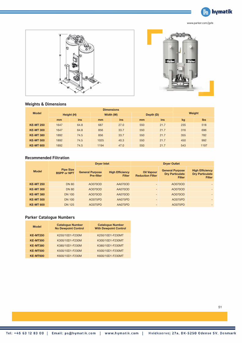
51
www.parker.com/gsfe
ModelPipe Size
BSPP or NPT
Dryer Inlet Dryer Outlet
General PurposePre-filter
High Efficiency Filter
Oil Vapour Reduction Filter
General Purpose Dry Particulate
Filter
High Efficiency Dry Particulate
Filter
KE-MT 250 DN 80 AO070OD AA070OD - AO070OD -
KE-MT 300 DN 80 AO070OD AA070OD - AO070OD -
KE-MT 380 DN 100 AO070OD AA070OD - AO070OD -
KE-MT 500 DN 100 AO075PD AA075PD - AO075PD -
KE-MT 600 DN 125 AO075PD AA075PD - AO075PD -
ModelDimensions
WeightHeight (H) Width (W) Depth (D)
mm ins mm ins mm ins kg lbs
KE-MT 250 1647 64.8 687 27.0 550 21.7 235 518
KE-MT 300 1647 64.8 856 33.7 550 21.7 316 696
KE-MT 380 1892 74.5 856 33.7 550 21.7 355 782
KE-MT 500 1892 74.5 1025 40.3 550 21.7 450 992
KE-MT 600 1892 74.5 1194 47.0 550 21.7 543 1197
Model Catalogue Number
No Dewpoint Control Catalogue Number
With Dewpoint Control
KE-MT250 K250/10D1-F230M K250/10D1-F230MT
KE-MT300 K300/10D1-F230M K300/10D1-F230MT
KE-MT380 K380/10D1-F230M K380/10D1-F230MT
KE-MT500 K500/10D1-F230M K500/10D1-F230MT
KE-MT600 K600/10D1-F230M K600/10D1-F230MT
Weights & Dimensions
Recommended Filtration
Parker Catalogue Numbers
W
H
D

52
Dryer ModelsDewpoint (Standard)
ISO8573-1:2010 Classification
(Standard)
Dewpoint (Option 1)
ISO8573-1:2010 Classification
(Option 1)
Dewpoint (Option 2)
ISO8573-1:2010 Classification
(Option 2)°C °F °C °F °C °F
MXLE -40 -40 Class 2.2.2 -70 -100 Class 2.1.2 -20 -4 Class 2.3.2
Dryer Models
Minimum Operating Pressure
Maximum Operating Pressure
Minimum Operating
Temperature
Maximum Operating
Temperature
Maximum Ambient
Temperature
Electrical Supply
(Standard)
Electrical Supply
(Optional)
Thread Type
Noise Level
bar g psi g bar g psi g °C °F °C °F °C °F dB(A)
MXLE 102C - MXLE 108
5 73 13 190 5 41 50 122 55 131400V
+/-10% 3PH 50Hz
460V +/-10%
3PH 60HzBSPP <75
Outlet Dewpoint°C -20 -40 -70
°F -4 -40 -100
Correction Factor 0.91 1.00 1.43
Stated flows are for operation at 7 bar (g) (102 psi g) with reference to 20°C, 1 bar (a), 0% relative water vapour pressure. For flows at other pressures, apply the correction factors shown below.
Maximum Inlet Temperature
°C 25 30 35 40 45 50
°F 77 86 95 104 113 122
Correction Factor 1.00 1.00 1.00 1.04 1.14 1.37
Maximum Ambient Temperature
°C 25 30 35 40 45 50
°F 77 86 95 104 113 122
Correction Factor 1.00 1.00 1.00 1.00 1.00 1.00
Minimum Inlet Pressure
bar g 4 5 6 7 8 9 10 11 12 13
psi g 58 73 87 100 116 131 145 160 174 189
Correction Factor 1.60 1.33 1.14 1.00 0.89 0.80 0.73 0.67 0.62 0.57
Product Selection & Correction FactorsFor correct operation, compressed air dryers must be sized using for the maximum (summer) inlet temperature, maximum (summer) ambient temperature, minimum inlet pressure, required outlet dewpoint and maximum flow rate of the installation.
To select a dryer, first calculate the MDC (Minimum Drying Capacity) using the formula below then select a dryer from the flow rate table above with a flow rate equal to or above the MDC.
Minimum Drying Capacity = System Flow x CFMIT x CFMAT x CFMIP x CFOD
ISO8573-1 Classifications when used with OIL-X pre / post filtration
MXLE Large Flow Heatless Low Energy Adsorption Dryers
Model Pipe SizeInlet Flow Rate
L/s m3/min m3/hr cfm
MXLE 102C 2" 113 6.81 408 240
MXLE 103C 2" 170 10.22 612 360
MXLE 103 2" 213 12.75 765 450
MXLE 104 21/2" 283 17 1020 600
MXLE 105 21/2" 354 21 1275 750
MXLE 106 21/2" 425 26 1530 900
MXLE 107 21/2" 496 30 1785 1050
MXLE 108 21/2" 567 34 2040 1200
For Higher Flow Capacities - Contact Parker
Compressed Air Dryers
Dryer Performance
Technical Data
Flow Rates
CFMIT - Correction Factor Maximum Inlet Temperature
CFMAT - Correction Factor Maximum Ambient Temperature
CFMIP - Correction Factor Minimum Inlet Pressure
CFOD - Correction Factor Outlet Dewpoint
Vacuum Pump Part Number & kWVacuum Pump
50HzPump kW
50HZVacuum Pump
60HzPump kW
60Hz
MXLEP2C-E 3 MXLEP2C-E-60 4.8
MXLEP3C-E 3 MXLEP3C-E-60 4.8
MXLEP3-E 4 MXLEP3-E-60 6.5
MXLEP4-E 5.5 MXLEP4-E-60 9
MXLEP5-E 5.5 MXLEP5-E-60 9
MXLEP6-E 8 MXLEP6-E-60 13
MXLEP7-E 9.5 MXLEP7-E-60 15.5
MXLEP8-E 9.5 MXLEP8-E-60 15.5
Dryer & vacuum pump to be ordered separately.

53
www.parker.com/gsfe
ModelPipe Size
BSPP
Dryer Inlet Dryer Outlet
General Purpose Pre-filter
High Efficiency Filter
Oil Vapour Reduction Filter
General Purpose Dry Particulate
Filter
High Efficiency Dry Particulate
Filter
MXLE 102C 2" AOP040H AAP040H - AOP040H -
MXLE 103C 2" AOP040H AAP040H - AOP040H -
MXLE 103 2" AOP040H AAP040H - AOP040H -
MXLE 104 21/2" AOP045I AAP045I - AOP045I -
MXLE 105 21/2" AOP050I AAP050I - AOP050I -
MXLE 106 21/2" AOP050I AAP050I - AOP050I -
MXLE 107 21/2" AOP055I AAP055I - AOP055I -
MXLE 108 21/2" AOP055I AAP055I - AOP055I -
Model
Dimensions (Dryer Only)Weight (Dryer Only)
Height (H) Width (W) Depth (D)
mm ins mm ins mm ins kg lbs
MXLE 102C 1647 64.8 793 31.5 550 21.7 265 583
MXLE 103C 1647 64.8 962 37.9 550 21.7 346 761
MXLE 103 1892 74.5 962 37.9 550 21.7 385 847
MXLE 104 1892 74.5 1131 44.6 550 21.7 480 1056
MXLE 105 1892 74.5 1300 51.2 550 21.7 573 1261
MXLE 106 1892 74.5 1469 57.9 550 21.7 667 1467
MXLE 107 1892 74.5 1641 64.6 550 21.7 761 1674
MXLE 108 1892 74.5 1807 71.2 550 21.7 855 1881
Model Catalogue Number
-20°C PDP / -40°CPDP
Catalogue Number-70°C PDP
50Hz Vacuum Pump Part Numbers
60Hz Vacuum Pump Part Numbers
Dryer Upgrade Kit Part Numbers
MXLE102C MXLE102C MXLE102C-70 MXLEP2C-E MXLEP2C-E-60 MXLEK2C
MXLE103C MXLE103C MXLE103C-70 MXLEP3C-E MXLEP3C-E-60 MXLEK3C
MXLE103 MXLE103 MXLE103-70 MXLEP3-E MXLEP3-E-60 MXLEK3
MXLE104 MXLE104 MXLE104-70 MXLEP4-E MXLEP4-E-60 MXLEK4
MXLE105 MXLE105 MXLE105-70 MXLEP5-E MXLEP5-E-60 MXLEK5
MXLE106 MXLE106 MXLE106-70 MXLEP6-E MXLEP6-E-60 MXLEK6
MXLE107 MXLE107 MXLE107-70 MXLEP7-E MXLEP7-E-60 MXLEK7
MXLE108 MXLE108 MXLE108-70 MXLEP8-E MXLEP8-E-60 MXLEK8
Included Filtration
Weights & Dimensions
Parker Catalogue Numbers
W
H
D
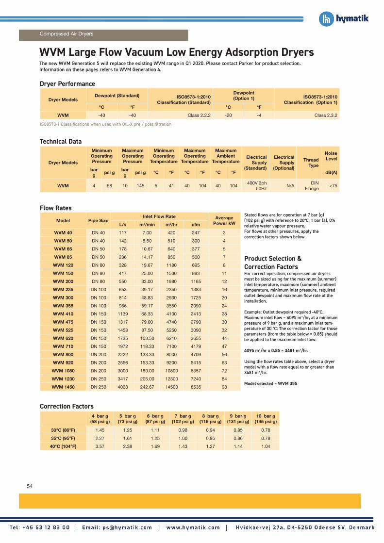
54
Dryer ModelsDewpoint (Standard) ISO8573-1:2010
Classification (Standard)
Dewpoint (Option 1) ISO8573-1:2010
Classification (Option 1)°C °F °C °F
WVM -40 -40 Class 2.2.2 -20 -4 Class 2.3.2
Dryer Models
Minimum Operating Pressure
Maximum Operating Pressure
Minimum Operating
Temperature
Maximum Operating
Temperature
Maximum Ambient
TemperatureElectrical
Supply (Standard)
Electrical Supply
(Optional)
Thread Type
Noise Level
bar g
psi gbar g
psi g °C °F °C °F °C °F dB(A)
WVM 4 58 10 145 5 41 40 104 40 104400V 3ph
50HzN/A
DIN Flange
<75
Stated flows are for operation at 7 bar (g) (102 psi g) with reference to 20°C, 1 bar (a), 0% relative water vapour pressure. For flows at other pressures, apply the correction factors shown below.
Product Selection & Correction Factors
For correct operation, compressed air dryers must be sized using for the maximum (summer) inlet temperature, maximum (summer) ambient temperature, minimum inlet pressure, required outlet dewpoint and maximum flow rate of the installation.
Example: Outlet dewpoint required -40°C. Maximum inlet flow = 4095 m³/hr, at a minimum pressure of 9 bar g, and a maximum inlet tem-perature of 30 °C: The correction factor for those parameters (from the table below = 0.85) should be applied to the maximum inlet flow.
4095 m³/hr x 0.85 = 3481 m³/hr.
Using the flow rates table above, select a dryer model with a flow rate equal to or greater than 3481 m³/hr. Model selected = WVM 355
ISO8573-1 Classifications when used with OIL-X pre / post filtration
Model Pipe SizeInlet Flow Rate Average
Power kWL/s m3/min m3/hr cfm
WVM 40 DN 40 117 7.00 420 247 3
WVM 50 DN 40 142 8.50 510 300 4
WVM 65 DN 50 178 10.67 640 377 5
WVM 85 DN 50 236 14.17 850 500 7
WVM 120 DN 80 328 19.67 1180 695 8
WVM 150 DN 80 417 25.00 1500 883 11
WVM 200 DN 80 550 33.00 1980 1165 12
WVM 235 DN 100 653 39.17 2350 1383 16
WVM 300 DN 100 814 48.83 2930 1725 20
WVM 355 DN 100 986 59.17 3550 2090 24
WVM 410 DN 150 1139 68.33 4100 2413 28
WVM 475 DN 150 1317 79.00 4740 2790 30
WVM 525 DN 150 1458 87.50 5250 3090 32
WVM 620 DN 150 1725 103.50 6210 3655 44
WVM 710 DN 150 1972 118.33 7100 4179 47
WVM 800 DN 200 2222 133.33 8000 4709 56
WVM 920 DN 200 2556 153.33 9200 5415 63
WVM 1080 DN 200 3000 180.00 10800 6357 72
WVM 1230 DN 250 3417 205.00 12300 7240 84
WVM 1450 DN 250 4028 242.67 14500 8535 98
4 bar g(58 psi g)
5 bar g(73 psi g)
6 bar g(87 psi g)
7 bar g (102 psi g)
8 bar g (116 psi g)
9 bar g (131 psi g)
10 bar g (145 psi g)
30°C (86°F) 1.45 1.25 1.11 0.98 0.94 0.85 0.78
35°C (95°F) 2.27 1.61 1.25 1.00 0.95 0.86 0.78
40°C (104°F) 3.57 2.38 1.69 1.43 1.27 1.14 1.04
WVM Large Flow Vacuum Low Energy Adsorption Dryers
Compressed Air Dryers
Dryer Performance
Technical Data
Flow Rates
Correction Factors
Product Selection & Correction Factors
The new WVM Generation 5 will replace the existing WVM range in Q1 2020. Please contact Parker for product selection.Information on these pages refers to WVM Generation 4.

55
www.parker.com/gsfe
Model
Dimensions (Dryer Only) Weight (Dryer Only)Height (H) Width (W) Depth (D)
mm ins mm ins mm ins kg lbs
WVM 40 2230 87.8 1140 44.9 990 39.0 770 1698
WVM 50 2230 87.8 1140 44.9 990 39.0 770 1698
WVM 65 2300 90.6 1260 49.6 1110 43.7 800 1764
WVM 85 2300 90.6 1260 49.6 1110 43.7 800 1764
WVM 120 2690 105.9 1460 57.5 1160 45.7 1150 2535
WVM 150 2700 106.3 1540 60.6 1200 47.2 1300 2866
WVM 200 2750 108.3 1605 63.2 1405 55.3 1650 3638
WVM 235 2870 113.0 2025 79.7 1490 58.7 2000 4409
WVM 300 2890 113.8 2050 80.7 1565 61.6 2250 4960
WVM 355 2960 116.5 2160 85.0 1750 68.9 2650 5842
WVM 410 3230 127.2 2430 95.7 1710 67.3 3250 7165
WVM 475 3260 128.3 2490 98.0 1710 67.3 3650 8047
WVM 525 3265 128.5 2550 100.4 1775 69.9 4050 8929
WVM 620 3540 139.4 2570 101.4 1865 73.4 4700 10362
WVM 710 3560 140.2 2635 103.7 1900 74.8 5050 11133
WVM 800 3625 142.7 3085 121.5 2110 83.1 6450 14220
WVM 920 3645 143.5 3125 123.0 2235 88.0 7500 16535
WVM 1080 3710 146.1 3225 127.0 2285 90.0 8700 19180
WVM 1230 4050 159.4 3475 136.8 2350 92.5 11900 26235
WVM 1450 4200 165.4 3500 137.8 2380 93.7 15870 34987
Weights & Dimensions
W
H
D

56
Model Pipe Size
Dryer Inlet Dryer Outlet
General Purpose Pre-filter
High Efficiency Filter
Oil Vapour Reduction Filter
General Purpose Dry Particulate
Filter
High Efficiency Dry Particulate
Filter
WVM 40 DN 40 AOP035GGFX AAP035GGFX - AOP035GGMX -
WVM 50 DN 40 AOP035GGFX AAP035GGFX - AOP035GGMX -
WVM 65 DN 50 AOP040HGFX AAP040HGFX - AOP040HGMX -
WVM 85 DN 50 AOP045IGFX AAP045IGFX - AOP045IGMX -
WVM 120 DN 80 AO065NDFX AA065NDFX - AO065NDMX -
WVM 150 DN 80 AO065NDFX AA065NDFX - AO065NDMX -
WVM 200 DN 80 AO065NDFX AA065NDFX - AO065NDMX -
WVM 235 DN 100 AO070ODFX AA070ODFX - AO070ODMX -
WVM 300 DN 100 AO070ODFX AA070ODFX - AO070ODMX -
WVM 355 DN 100 AO070ODFX AA070ODFX - AO070ODMX -
WVM 410 DN 150 AO075PDFX AA075PDFX - AO075PDMX -
WVM 475 DN 150 AO075PDFX AA075PDFX - AO075PDMX -
WVM 525 DN 150 AO075PDFX AA075PDFX - AO075PDMX -
WVM 620 DN 150 AO075PDFX AA075PDFX - AO075PDMX -
WVM 710 DN 150 AO080PDFX AA080PDFX - AO080PDMX -
WVM 800 DN 200 AO085QDFX AA085QDFX - AO085QDMX -
WVM 920 DN 200 AO085QDFX AA085QDFX - AO085QDMX -
WVM 1080 DN 200 AO085QDFX AA085QDFX - AO085QDMX -
WVM 1230 DN 250 AO090RDFX AA090RDFX - AO090RDMX -
WVM 1450 DN 250 AO090RDFX AA090RDFX - AO090RDMX -
WVM Large Flow Vacuum Low Energy Adsorption Dryers
Compressed Air Dryers
Recommended Filtration

57
www.parker.com/gsfe
Model Catalogue NumberStandard Dryer with
Dewpoint Control
Catalogue NumberPlus Vessel Insulation
WVM 40 W40/10VM4-F400CT W40/10VM4-F400CT/I
WVM 50 W50/10VM4-F400CT W50/10VM4-F400CT/I
WVM 65 W65/10VM4-F400CT W65/10VM4-F400CT/I
WVM 85 W85/10VM4-F400CT W85/10VM4-F400CT/I
WVM 120 W120/10VM4-F400CT W120/10VM4-F400CT/I
WVM 150 W150/10VM4-F400CT W150/10VM4-F400CT/I
WVM 200 W200/10VM4-F400CT W200/10VM4-F400CT/I
WVM 235 W235/10VM4-F400CT W235/10VM4-F400CT/I
WVM 300 W300/10VM4-F400CT W300/10VM4-F400CT/I
WVM 355 W355/10VM4-F400CT W355/10VM4-F400CT/I
WVM 410 W410/10VM4-F400CT W410/10VM4-F400CT/I
WVM 475 W475/10VM4-F400CT W475/10VM4-F400CT/I
WVM 525 W525/10VM4-F400CT W525/10VM4-F400CT/I
WVM 620 W620/10VM4-F400CT W620/10VM4-F400CT/I
WVM 710 W710/10VM4-F400CT W710/10VM4-F400CT/I
WVM 800 W800/10VM4-F400CT W800/10VM4-F400CT/I
WVM 920 W920/10VM4-F400CT W920/10VM4-F400CT/I
WVM 1080 W1080/10VM4-F400CT W1080/10VM4-F400CT/I
WVM 1230 W1230/10VM4-F400CT W1230/10VM4-F400CT/I
WVM 1450 W1450/10VM4-F400CT W1450/10VM4-F400CT/I
Parker Catalogue Numbers

58
Dryer ModelsDewpoint (Standard)
ISO8573-1:2010 Classification
(Standard)
Dewpoint (Option 1)
ISO8573-1:2010 Classification
(Option 1)
Dewpoint (Option 2)
ISO8573-1:2010 Classification
(Option 2)°C °F °C °F °C °F
ATT -40 -40 Class 2.2.2 -70 -100 Class 2.1.2 -20 -4 Class 2.3.2
Stated flows are for operation at 7 bar (g) (102 psi g) with reference to 20°C, 1 bar (a), 0% relative water vapour pressure. For flows at other pressures, apply the correction factors shown below.
Product Selection & Correction FactorsFor correct operation, compressed air dryers must be sized using for the maximum (summer) inlet temperature, maximum (summer) ambient temperature, minimum inlet pressure, required outlet dewpoint and maximum flow rate of the installation.
To select a dryer, first calculate the MDC (Minimum Drying Capacity) using the formula below then select a dryer from the flow rate table above with a flow rate equal to or above the MDC.
Minimum Drying Capacity = System Flow x CFMIT x CFMAT x CFMIP x CFOD
ISO8573-1 Classifications when used with OIL-X pre / post filtration
ModelPipe Size
Inlet Flow Rate Average Power kWL/s m3/min m3/hr cfm
ATT 040 1" 67 4 240 141 1.3
ATT 060 11/2" 100 6 360 212 1.27
ATT 090 11/2" 150 9 540 318 1.94
ATT 140 2" 233 14 840 494 2.01
ATT 260 21/2" 433 26 1560 918 4.02
ATT 340 21/2" 567 34 2040 1200 5.17
Maximum Inlet Temperature
°C 25 30 35 40 45 50 55 60 65
°F 77 86 95 104 113 122 131 140 149
Correction Factor 040 - 340 0.82 0.82 1.00 1.23 1.45 1.69 1.92 2.17 2.50
Maximum Ambient Temperature
°C 20 25 30 35 40 45 50
°F 68 77 86 95 104 113 122
Correction Factor 040 - 060 0.95 1.00 1.06 1.14 1.23 1.33 1.47
Correction Factor 090 - 340 0.94 1.00 1.05 1.11 1.20 1.30 1.39
Minimum Inlet Pressure
bar g 4 5 6 7 8 9 10 11 12 13 14 15 16
psi g 58 73 87 100 116 131 145 160 174 189 203 218 232
Correction Factor 040 1.61 1.33 1.15 1.00 0.93 0.83 0.78 0.75 0.71 0.69 0.67 0.65 0.63
Correction Factor 060 - 340 1.61 1.33 1.15 1.00 0.93 0.83 0.78 0.75 0.71 N/A N/A N/A N/A
ATT Low Energy Hybrid Dryers
Compressed Air Dryers
Dryer Models
Minimum Operating Pressure
Maximum Operating Pressure
Minimum Operating
Temperature
Maximum Operating
Temperature
Maximum Ambient
Temperature
Electrical Supply
(Standard)
Electrical Supply
(Optional)
Thread Type
Noise Level
bar g psi g bar g psi g °C °F °C °F °C °F dB(A)
ATT 040 2 29 16 232 5 41 65 149 50 122230V 1ph
50HzN/A BSPP <75
ATT 060 - 090 2 29 12 174 5 41 65 149 50 122230V 1ph
50HzN/A BSPP <75
ATT 090 - 140 2 29 12 174 5 41 65 149 50 122400V 3ph
50HzN/A BSPP <75
ATT 260 - 340 4 58 12 174 5 41 65 149 50 122400V 3ph
50HzN/A BSPP <75
Technical Data
Dryer Performance
CFMIT - Correction Factor Maximum Inlet Temperature
Flow Rates
CFMAT - Correction Factor Maximum Ambient Temperature
CFMIP - Correction Factor Minimum Inlet Pressure
CFOD - Correction Factor Outlet Dewpoint
Outlet Dewpoint°C -20 -40 -70
°F -4 -40 -100
Correction Factor 1 1 1

59
www.parker.com/gsfe
ModelPipe Size
BSPP
Dryer Inlet Dryer Outlet
General Purpose Pre-filter
High Efficiency Filter
Oil Vapour Reduction Filter
General Purpose Dry
Particulate Filter
High Efficiency Dry Particulate
Filter
ATT 040 1" AOP030G AAP030G - AOP030G -
ATT 060 11/2" AOP030G AAP030G - AOP030G -
ATT 090 11/2" AOP035G AAP035G - AOP035G -
ATT 140 2" AOP045I AAP045I - AOP045I -
ATT 260 21/2" AOP055J AAP055J - AOP055J -
ATT 340 21/2" AOP055J AAP055J - AOP055J -
Model
Dimensions (Dryer Only) Weight (Dryer Only)Height (H) Width (W) Depth (D)
mm ins mm ins mm ins kg lbs
ATT 040 1064 41.9 706 27.8 1246 49.1 200 441
ATT 060 1214 47.8 806 31.7 1416 55.7 295 650
ATT 090 1214 47.8 806 31.7 1416 55.7 335 739
ATT 140 1586 62.4 1007 39.6 1345 53.0 490 1080
ATT 260 1720 67.7 1007 39.6 2535 99.8 880 1940
ATT 340 1720 67.7 1007 39.6 2535 99.8 950 2094
Model Catalogue Number
Standard Catalogue Number
With By-Pass Catalogue NumberWith Touchscreen
Catalogue NumberWith By-Pass &
Touchscreen
ATT 040 ATT040-A23015016TI - - -
ATT 060 ATT060-A23015012TI ATT060-A23015012TITB - -
ATT 090 ATT090-A23015012TI ATT090-A23015012TITB - -
ATT 140 ATT140-A40035012EI ATT140-A40035012EITB ATT140-A40035012EITS ATT140-A40035012EITBTS
ATT 260 ATT260-A40035012EI ATT260-A40035012EITB ATT260-A40035012EITS ATT260-A40035012EITBTS
ATT 340 ATT340-A40035012EI ATT340-A40035012EITB ATT340-A40035012EITS ATT340-A40035012EITBTS
Weights & Dimensions
Included Filtration
Parker Catalogue Numbers
W
H
D
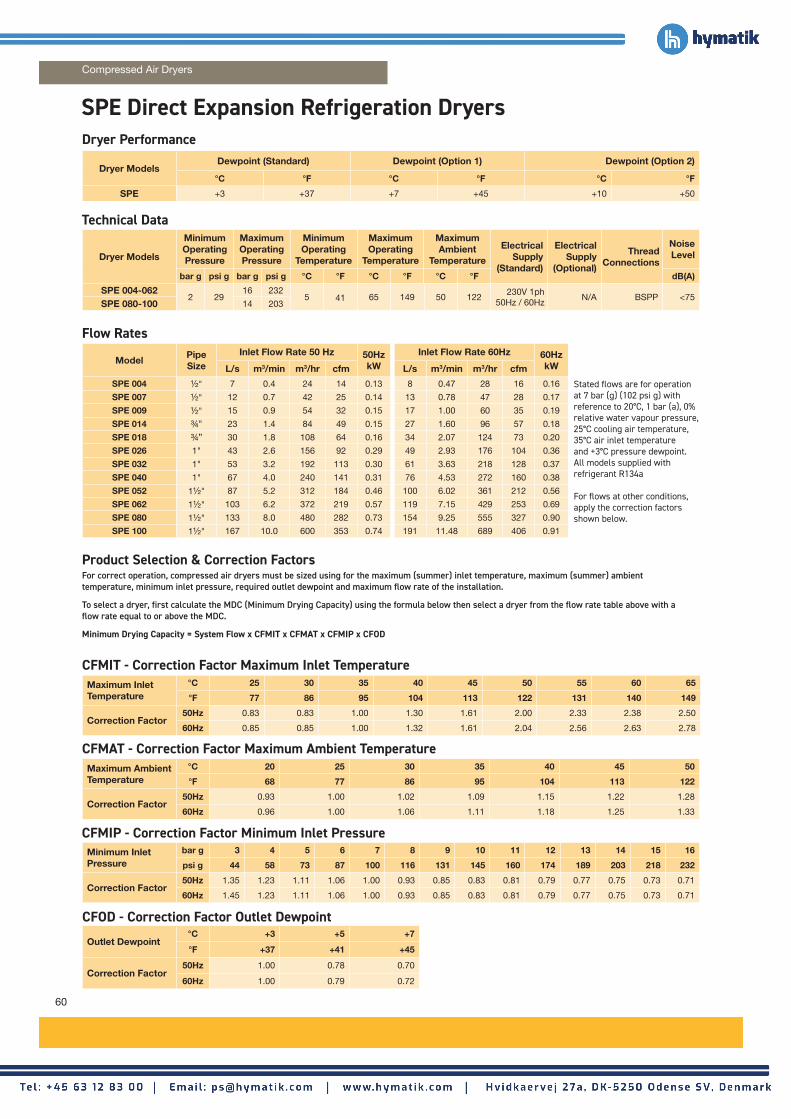
60
ModelPipe Size
Inlet Flow Rate 50 Hz 50HzkW
Inlet Flow Rate 60Hz 60HzkWL/s m3/min m3/hr cfm L/s m3/min m3/hr cfm
SPE 004 1/2" 7 0.4 24 14 0.13 8 0.47 28 16 0.16
SPE 007 1/2" 12 0.7 42 25 0.14 13 0.78 47 28 0.17
SPE 009 1/2" 15 0.9 54 32 0.15 17 1.00 60 35 0.19
SPE 014 3/4" 23 1.4 84 49 0.15 27 1.60 96 57 0.18
SPE 018 3/4” 30 1.8 108 64 0.16 34 2.07 124 73 0.20
SPE 026 1" 43 2.6 156 92 0.29 49 2.93 176 104 0.36
SPE 032 1" 53 3.2 192 113 0.30 61 3.63 218 128 0.37
SPE 040 1" 67 4.0 240 141 0.31 76 4.53 272 160 0.38
SPE 052 11/2" 87 5.2 312 184 0.46 100 6.02 361 212 0.56
SPE 062 11/2" 103 6.2 372 219 0.57 119 7.15 429 253 0.69
SPE 080 11/2" 133 8.0 480 282 0.73 154 9.25 555 327 0.90
SPE 100 11/2" 167 10.0 600 353 0.74 191 11.48 689 406 0.91
Stated flows are for operation at 7 bar (g) (102 psi g) with reference to 20°C, 1 bar (a), 0% relative water vapour pressure, 25°C cooling air temperature, 35°C air inlet temperature and +3°C pressure dewpoint. All models supplied with refrigerant R134a
For flows at other conditions, apply the correction factors shown below.
Product Selection & Correction FactorsFor correct operation, compressed air dryers must be sized using for the maximum (summer) inlet temperature, maximum (summer) ambient temperature, minimum inlet pressure, required outlet dewpoint and maximum flow rate of the installation.
To select a dryer, first calculate the MDC (Minimum Drying Capacity) using the formula below then select a dryer from the flow rate table above with a flow rate equal to or above the MDC.
Minimum Drying Capacity = System Flow x CFMIT x CFMAT x CFMIP x CFOD
Dryer Models
Minimum Operating Pressure
Maximum Operating Pressure
Minimum Operating
Temperature
Maximum Operating
Temperature
Maximum Ambient
Temperature
Electrical Supply
(Standard)
Electrical Supply
(Optional)
Thread Connections
Noise Level
bar g psi g bar g psi g °C °F °C °F °C °F dB(A)
SPE 004-0622 29
16 2325 41 65 149 50 122
230V 1ph 50Hz / 60Hz
N/A BSPP <75SPE 080-100 14 203
Maximum Inlet Temperature
°C 25 30 35 40 45 50 55 60 65
°F 77 86 95 104 113 122 131 140 149
Correction Factor 50Hz 0.83 0.83 1.00 1.30 1.61 2.00 2.33 2.38 2.50
60Hz 0.85 0.85 1.00 1.32 1.61 2.04 2.56 2.63 2.78
Maximum Ambient Temperature
°C 20 25 30 35 40 45 50
°F 68 77 86 95 104 113 122
Correction Factor50Hz 0.93 1.00 1.02 1.09 1.15 1.22 1.28
60Hz 0.96 1.00 1.06 1.11 1.18 1.25 1.33
Minimum Inlet Pressure
bar g 3 4 5 6 7 8 9 10 11 12 13 14 15 16
psi g 44 58 73 87 100 116 131 145 160 174 189 203 218 232
Correction Factor 50Hz 1.35 1.23 1.11 1.06 1.00 0.93 0.85 0.83 0.81 0.79 0.77 0.75 0.73 0.71
60Hz 1.45 1.23 1.11 1.06 1.00 0.93 0.85 0.83 0.81 0.79 0.77 0.75 0.73 0.71
Outlet Dewpoint°C +3 +5 +7
°F +37 +41 +45
Correction Factor50Hz 1.00 0.78 0.70
60Hz 1.00 0.79 0.72
SPE Direct Expansion Refrigeration Dryers
Dryer ModelsDewpoint (Standard) Dewpoint (Option 1) Dewpoint (Option 2)
°C °F °C °F °C °F
SPE +3 +37 +7 +45 +10 +50
Compressed Air Dryers
Dryer Performance
Flow Rates
Technical Data
CFMIT - Correction Factor Maximum Inlet Temperature
CFMAT - Correction Factor Maximum Ambient Temperature
CFMIP - Correction Factor Minimum Inlet Pressure
CFOD - Correction Factor Outlet Dewpoint

61
www.parker.com/gsfe
ModelDimensions
WeightPipe Size
BSPP
Dryer Inlet Dryer Outlet
Height (H) Width (W) Depth (D) General Purpose Pre-Filter
High Efficiency Post Filtermm ins mm ins mm ins kg lbs
SPE 004 520 20.5 300 11.8 400 15.7 24 53 1/2" AOP010C AAP010C
SPE 007 520 20.5 300 11.8 400 15.7 24 53 1/2" AOP015C AAP015C
SPE 009 520 20.5 300 11.8 400 15.7 25 55 1/2" AOP015C AAP015C
SPE 014 580 22.8 330 13.0 550 21.7 35 77 3/4" AOP020D AAP020D
SPE 018 580 25.6 330 13.0 550 21.7 36 79 3/4" AOP020D AAP020D
SPE 026 650 25.6 400 15.7 630 24.8 46 101 1" AOP025E AAP025E
SPE 032 650 25.6 400 15.7 630 24.8 46 101 1" AOP025E AAP025E
SPE 040 650 25.6 400 15.7 630 24.8 47 104 1" AOP025E AAP025E
SPE 052 650 25.6 400 15.7 630 24.8 53 117 11/2" AOP030G AAP030G
SPE 062 650 25.6 400 15.7 630 24.8 55 121 11/2" AOP030G AAP030G
SPE 080 840 33.1 450 17.7 780 30.7 80 176 11/2" AOP035G AAP035G
SPE 100 840 33.1 450 17.7 780 30.7 80 176 11/2" AOP035G AAP035G
Model Catalogue NumberWith Timed Drain
Catalogue NumberWith Electronic Drain
Catalogue NumberWith Electronic Drain &
Energy Saving
Catalogue NumberWith External Float Drain
SPE 004 SPE004-A2301DF16TIS SPE004-A2301DF16EXS - SPE004-A2301DF16FHS
SPE 007 SPE007-A2301DF16TIS SPE007-A2301DF16EXS - SPE007-A2301DF16FHS
SPE 009 SPE009-A2301DF16TIS SPE009-A2301DF16EXS - SPE009-A2301DF16FHS
SPE 014 SPE014-A2301DF16TIS SPE014-A2301DF16EXS - SPE014-A2301DF16FHS
SPE 018 SPE018-A2301DF16TIS SPE018-A2301DF16EXS - SPE018-A2301DF16FHS
SPE 026 SPE026-A2301DF16TIS SPE026-A2301DF16EXS SPE026-A2301DF16EXSES SPE026-A2301DF16FHS
SPE 032 SPE032-A2301DF16TIS SPE032-A2301DF16EXS SPE032-A2301DF16EXSES SPE032-A2301DF16FHS
SPE 040 SPE040-A2301DF16TIS SPE040-A2301DF16EXS SPE040-A2301DF16EXSES SPE040-A2301DF16FHS
SPE 052 SPE052-A2301DF16TIS SPE052-A2301DF16EXS SPE052-A2301DF16EXSES SPE052-A2301DF16FHS
SPE 062 SPE062-A2301DF16TIS SPE062-A2301DF16EXS SPE062-A2301DF16EXSES SPE062-A2301DF16FHS
SPE 080 SPE080-A2301DF14TIS SPE080-A2301DF14EXS SPE080-A2301DF14EXSES SPE080-A2301DF14FHS
SPE 100 SPE100-A2301DF14TIS SPE100-A2301DF14EXS SPE100-A2301DF14EXSES SPE100-A2301DF14FHS
Weights & Dimensions Recommended Filtration
Parker Catalogue Numbers
W
H
D

62
Dryer Models
Minimum Operating Pressure
Maximum Operating Pressure
Minimum Operating
Temperature
Maximum Operating
Temperature
Maximum Ambient
Temperature
Electrical Supply
(Standard)
Electrical Supply
(Optional)
Thread Connections
Noise Level
bar g psi g bar g psi g °C °F °C °F °C °F dB(A)
PST 0120 - 1800 2 29 14 203 5 41 65 149 50 122400V 3ph
50HzN/A
BSPP & DIN Flange
<75
Stated flows are for operation at 7 bar (g) (102 psi g) with reference to 20°C, 1 bar (a), 0% relative water vapour pressure, 25°C cooling air temperature, 35 °C air inlet temperature and +3°C pressure dewpoint. All models supplied with refrigerant R407C.
For flows at other conditions, apply the correction factors shown below.
Product Selection & Correction FactorsFor correct operation, compressed air dryers must be sized using for the maximum (summer) inlet temperature, maximum (summer) ambient temperature, minimum inlet pressure, required outlet dewpoint and maximum flow rate of the installation.
To select a dryer, first calculate the MDC (Minimum Drying Capacity) using the formula below then select a dryer from the flow rate table above with a flow rate equal to or above the MDC.
Minimum Drying Capacity = System Flow x CFMIT x CFMAT x CFMIP x CFOD
Maximum Ambient Temperature
°C 20 25 30 35 40 45 50
°F 68 77 86 95 104 113 122
Correction Factor 0.94 1.00 1.05 1.11 1.20 1.30 1.39
Minimum Inlet Pressure
bar g 3 4 5 6 7 8 9 10 11 12 13 14
psi g 44 58 73 87 100 116 131 145 160 174 189 203
Correction Factor 1.35 1.20 1.11 1.04 1.00 0.96 0.93 0.93 0.90 0.89 0.88 0.87
Outlet Dewpoint°C +3 +5 +7 +10
°F +37 +41 +45 +50
Correction Factor 1.00 0.91 0.83 0.71
ModelPipe Size
Inlet Flow Rate Average Power
kWL/s m3/min m3/hr cfm
PST 120 2" 200 12 720 424 1.13PST 140 2" 233 14 840 494 1.14PST 180 2" 300 18 1080 636 1.46PST 220 21/2" 367 22 1320 777 1.68PST 260 21/2" 433 26 1560 918 2.19PST 300 21/2" 500 30 1800 1059 2.41PST 350 21/2" 583 35 2100 1236 3.06PST 460 DN100 767 46 2760 1625 3.14PST 520 DN100 867 52 3120 1836 3.54PST 630 DN100 1050 63 3780 2225 4.64PST 750 DN150 1250 75 4500 2649 5.73PST 900 DN150 1500 90 5400 3178 7.63PST 1200 DN150 2000 120 7200 4238 8.92PST 1500 DN200 2500 150 9000 5297 12.35PST 1800 DN200 3000 180 10800 6357 15.96
Maximum Inlet Temperature
°C 25 30 35 40 45 50 55 60 65
°F 77 86 95 104 113 122 131 140 149
Correction Factor 0.81 0.81 1.00 1.19 1.43 1.69 2.00 2.22 2.50
PST Direct Expansion Refrigeration Dryers
Dryer ModelsDewpoint (Standard) Dewpoint (Option 1) Dewpoint (Option 2)
°C °F °C °F °C °F
PST +3 +37 +7 +45 +10 +50
Compressed Air Dryers
Dryer Performance
Technical Data
CFMIT - Correction Factor Maximum Inlet Temperature
CFMAT - Correction Factor Maximum Ambient Temperature
CFMIP - Correction Factor Minimum Inlet Pressure
CFOD - Correction Factor Outlet Dewpoint
Flow Rates

63
www.parker.com/gsfe
ModelDimensions
WeightPipe Size
BSPP
Dryer Inlet Dryer Outlet
Height (H) Width (W) Depth (D) General Purpose Pre-Filter
High Efficiency Post Filtermm ins mm ins mm ins kg lbs
PST 120 1064 41.9 706 27.8 1046 41.2 145 320 2" AOP040H AAP040H
PST 140 1064 41.9 706 27.8 1046 41.2 145 320 2" AOP040H AAP040H
PST 180 1064 41.9 706 27.8 1046 41.2 155 342 2" AOP045I AAP045I
PST 220 1316 51.8 806 31.7 1166 45.9 230 507 21/2" AOP050I AAP050I
PST 260 1316 51.8 806 31.7 1166 45.9 240 529 21/2" AOP055I AAP055I
PST 300 1316 51.8 806 31.7 1166 45.9 245 540 21/2" AOP055I AAP055I
PST 350 1316 51.8 806 31.7 1166 45.9 250 551 21/2" AOP055I AAP055I
PST 460 1690 66.5 1007 39.6 1097 43.2 470 1036 DN100 AO070O AO070O
PST 520 1722 67.8 1007 39.6 1097 43.2 490 1080 DN100 AO070O AA070O
PST 630 1722 67.8 1007 39.6 1657 65.2 580 1279 DN100 AO070O AA070O
PST 750 1722 67.8 1007 39.6 1657 65.2 670 1477 DN150 AO075P AA075P
PST 900 1722 67.8 1007 39.6 1657 65.2 690 1521 DN150 AO075P AA075P
PST 1200 2048 80.6 1007 39.6 1657 65.2 830 1830 DN150 AO080P AA080P
PST 1500 2208 86.9 1007 39.6 2257 88.9 1100 2425 DN200 AO085Q AA085Q
PST 1800 2208 86.9 1007 39.6 2257 88.9 1190 2623 DN200 AO085Q AA085Q
Model Catalogue Number
50Hz Air Cooled Catalogue Number50Hz Water Cooled
Catalogue Number60Hz Air Cooled
Catalogue Number60Hz Water Cooled
PST 120 PST120-A40035014EI - PST130-A46036014EI -
PST 140 PST140-A40035014EI - PST150-A46036014EI -
PST 180 PST180-A40035014EI - PST250-A46036014EI PST250-W46036014EI
PST 220 PST220-A40035014EI PST220-W40035014EI PST280-A46036014EI PST280-W46036014EI
PST 260 PST260-A40035014EI PST260-W40035014EI PST340-A46036014EI PST340-W46036014EI
PST 300 PST300-A40035014EI PST300-W40035014EI PST390-A46036014EI PST390-W46036014EI
PST 350 PST350-A40035014EI PST350-W40035014EI PST490-A46036014EI PST490-W46036014EI
PST 460 PST460-A40035014EI PST460-W40035014EI PST560-A46036014EI PST560-W46036014EI
PST 520 PST520-A40035014EI PST520-W40035014EI PST700-A46036014EI PST700-W46036014EI
PST 630 PST630-A40035014EI PST630-W40035014EI PST840-A46036014EI PST840-W46036014EI
PST 750 PST750-A40035014EI PST750-W40035014EI PST1020-A46036014EI PST1020-W46036014EI
PST 900 PST900-A40035014EI PST900-W40035014EI PST1320-A46036014EI PST1320-W46036014EI
PST 1200 PST1200-A40035014EI PST1200-W40035014EI PST1650-A46036014EI PST1650-W46036014EI
PST 1500 PST1500-A40035014EI PST1500-W40035014EI PST1980-A46036014EI PST1980-W46036014EI
PST 1800 PST1800-A40035014EI PST1800-W40035014EI
Weights & Dimensions Recommended Filtration
Parker Catalogue Numbers
W
H
D

64
ModelPipe Size
Inlet Flow Rate Average Power
kWL/s m3/min m3/hr cfm
PST 2400 DN200 4000 240 14400 8470 18
PST 3000 DN250 5000 300 18000 10588 25
PST 3600 DN250 6000 360 21600 12705 32
Dryer ModelsDewpoint (Standard) Dewpoint (Option 1) Dewpoint (Option 2)
°C °F °C °F °C °FPST +3 +37 +7 +45 +10 +50
PST Twin Direct Expansion Refrigeration Dryers
Dryer Models
Minimum Operating Pressure
Maximum Operating Pressure
Minimum Operating
Temperature
Maximum Operating
Temperature
Maximum Ambient
Temperature
Electrical Supply
(Standard)
Electrical Supply
(Optional)
Thread Connections
Noise Level
bar g psi g bar g psi g °C °F °C °F °C °F dB(A)
PST 2400 - 3600 2 29 14 203 5 41 65 149 50 122400V 3ph
50HzN/A DIN Flange <75
Stated flows are for operation at 7 bar (g) (102 psi g) with reference to 20°C, 1 bar (a), 0% relative water vapour pressure, 25°C cooling air temperature, 35 °C air inlet temperature and +3°C pressure dewpoint. All models supplied with refrigerant R407C.
For flows at other conditions, apply the correction factors shown below.
Product Selection & Correction FactorsFor correct operation, compressed air dryers must be sized using for the maximum (summer) inlet temperature, maximum (summer) ambient temperature, minimum inlet pressure, required outlet dewpoint and maximum flow rate of the installation.
To select a dryer, first calculate the MDC (Minimum Drying Capacity) using the formula below then select a dryer from the flow rate table above with a flow rate equal to or above the MDC.
Minimum Drying Capacity = System Flow x CFMIT x CFMAT x CFMIP x CFOD
Maximum Ambient Temperature
°C 20 25 30 35 40 45 50
°F 68 77 86 95 104 113 122
Correction Factor 0.94 1.00 1.05 1.11 1.20 1.30 1.39
Minimum Inlet Pressure
bar g 3 4 5 6 7 8 9 10 11 12 13 14
psi g 44 58 73 87 100 116 131 145 160 174 189 203
Correction Factor 1.35 1.20 1.11 1.04 1.00 0.96 0.93 0.93 0.90 0.89 0.88 0.87
Outlet Dewpoint°C +3 +5 +7 +10
°F +37 +41 +45 +50
Correction Factor 1.00 0.91 0.83 0.71
Maximum Inlet Temperature
°C 25 30 35 40 45 50 55 60 65
°F 77 86 95 104 113 122 131 140 149
Correction Factor 0.81 0.81 1.00 1.19 1.43 1.69 2.00 2.22 2.50
Compressed Air Dryers
Dryer Performance
Technical Data
Flow Rates
CFMIT - Correction Factor Maximum Inlet Temperature
CFMAT - Correction Factor Maximum Ambient Temperature
CFMIP - Correction Factor Minimum Inlet Pressure
CFOD - Correction Factor Outlet Dewpoint
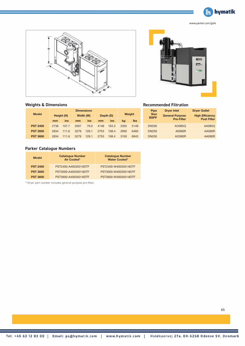
65
www.parker.com/gsfe
ModelCatalogue Number
Air Cooled*Catalogue Number
Water Cooled*
PST 2400 PST2400-A40035014EITF PST2400-W40035014EITF
PST 3000 PST3000-A40035014EITF PST3000-W40035014EITF
PST 3600 PST3600-A40035014EITF PST3600-W40035014EITF
ModelDimensions
WeightPipe Size
BSPP
Dryer Inlet Dryer Outlet
Height (H) Width (W) Depth (D) General PurposePre-Filter
High Efficiency Post Filtermm ins mm ins mm ins kg lbs
PST 2400 2736 107.7 2007 79.0 4148 163.3 2335 5148 DN200 AO085Q AA085Q
PST 3000 2834 111.6 3279 129.1 2753 108.4 2930 6460 DN250 A0090R AA090R
PST 3600 2834 111.6 3279 129.1 2753 108.4 3150 6945 DN250 AO090R AA090R
* Dryer part number includes general purpose pre-filter.
Parker Catalogue Numbers
Weights & Dimensions Recommended Filtration
H
D
W

66
Filtration Grade
Filter Type
Particle Reduction (inc water & oil
aerosols)
Maximum Remaining Oil Content
at 21°C (70°F)
Filtration Efficiency
Initial Dry Differential
Pressure
Initial Saturated Differential
Pressure
Change Element
Every
Precede with Filtration
Grade
WSLiquid Oil &
WaterN/A N/A >90% N/A
<70 mbar (<1 psi)
N/A N/A
AOCoalescing &
Dry ParticulateDown to 1 micron
0.5 mg/m³ 0.5 ppm(w)
99.925%<70 mbar
(<1 psi)<140 mbar
(<2 psi)12 months WS
AACoalescing &
Dry ParticulateDown to 0.01
micron0.01 mg/m³
0.01 ppm(w)99.9999%
<140 mbar (<1.5 psi)
<200 mbar (<3 psi)
12 months AO
ACSOil Vapour Reduction
N/A0.003 mg/m³
0.003 ppm(w)N/A
<140 mbar (<1.5 psi)
N/AWhen oil vapour is detected
A0+AA
FiltrationGrade
Filter ModelsMinimum Operating
PressureMaximum Operating
PressureMinimum Operating
TemperatureMaximum Operating
Temperature
bar g psi g bar g psi g ºC ºF ºC ºF
AO/AA IP50 010 - IP50 070 20 290 50 725 2 35 100 212
ACS IP50 010 - IP50 070 20 290 50 725 2 35 30 86
To correctly select a filter model, the flow rate of the filter must be adjusted for the minimum operating (inlet) pressure at the point of installation.1. Obtain the minimum operating (inlet) pressure and maximum compressed air flow rate at the inlet of the filter.2. Select the correction factor for minimum inlet pressure from the table (always round down e.g. for 33 bar, use 30 bar correction factor)3. Calculate the minimum filtration capacity. Minimum Filtration Capacity = Compressed Air Flow Rate x CFMIP 4. Using the minimum filtration capacity, select a filter model from the flow rate tables above (filter selected must have a flow rate equal to or greater than
the minimum filtration capacity).
CFMIP - Correction Factor Minimum Inlet PressureMinimumInlet Pressure
bar g 20 25 30 35 40 45 50
psi g 290 362 435 507 580 652 725
Correction Factor 2.43 1.96 1.65 1.42 1.24 1.11 1.00
Stated flows are for operation at 7 bar (g) (102 psi g) with reference to 20°C, 1 bar (a), 0% relative water vapour pressure. For flows at other pressures, apply the correction factors shown below.
Filtration Performance
Technical Data
Product Selection & Correction Factors
Filter Coding Example
Grade Model Pipe Size Thread Drain
Option
Incident Monitor Option
WSAOAA
ACS
Cde denotes filter housing
size
Letter denotespipe size
G = BSPP
F = AutomaticM = Manual X = None
Example code
AO IP50 010 A G F X
ModelPipe Size
L/S m³/min m³/hr cfmReplacement
ElementNo.
IP50 010AG X 1/4" 30 1.8 108 64 K009 1
IP50 020BG X 3/8" 45 2.7 162 95 K009 1
IP50 030CG X 1/2" 95 5.7 342 201 K030 1
IP50 040DG X 3/4" 145 8.7 522 307 K030 1
IP50 050EG X 1" 285 17.1 1026 604 K145 1
IP50 060GG X 11/2" 465 27.9 1674 985 K145 1
IP50 070HG X 2" 965 57.9 3473 2044 K220 1
Grade
Grade
Grade
Grade
Grade
Grade
Grade
Grade
Grade
Grade
Grade
Grade
Grade
Grade
= Replace with drain type - F (Automatic) for WS water separator and AO & AA coalescing filters or M (manual) for AO & AA dry particulate and ACS oil vapour reduction filters.
Important Note:
Using the same filter housings as their coalescing and dry particulate counterparts in the OIL-X IP50 range, Grade ACS filter elements differ in that they utilise a deep wrapped bed of carbon cloth to adsorb oil vapour. It is important to note, in-line adsorption filter elements have a different life span compared to coalescing and dry particulate filters and require more frequent element changes.
IP50 - 50 Bar Compressed Air Filters
Flow Rates
Compressed Air Filters and Dryers (20 bar to 350 bar)

67
www.parker.com/gsfe
ModelHeight (H) Width (W) Depth (D) Weight
mm ins mm ins mm ins kg lbs
IP50 010 175 6.9 78 3.1 68 2.7 1.3 2.9
IP50 020 175 6.9 78 3.1 68 2.7 1.3 2.9
IP50 030 245 9.6 89 3.5 84 3.3 2.0 4.4
IP50 040 245 9.6 89 3.5 84 3.3 2.0 4.4
IP50 050 423 16.6 122 4.8 116 4.6 5.0 11.0
IP50 060 423 16.6 122 4.8 116 4.6 5.0 11.0
IP50 070 480 18.9 170 6.7 162 6.4 10.0 22.0
Weight & Dimensions
ModelCatalogue NumberGeneral Purpose
Coalescing Filters
Catalogue NumberGeneral Purpose
Dry Particulate Filters
Catalogue NumberHigh Effi ciency
Coalescing Filters
Catalogue NumberHigh Effi ciency
Dry Particulate Filters
Catalogue NumberOil Vapour Reduction
Filters
IP50 010 AOIP50-010-AGFX AOIP50-010-AGMX AAIP50-010-AGFX AAIP50-010-AGMX ACSIP50-010-AGMX
IP50 020 AOIP50-020-BGFX AOIP50-020-BGMX AAIP50-020-BGFX AAIP50-020-BGMX ACSIP50-020-BGMX
IP50 030 AOIP50-030-CGFX AOIP50-030-CGMX AAIP50-030-CGFX AAIP50-030-CGMX ACSIP50-030-CGMX
IP50 040 AOIP50-040-DGFX AOIP50-040-DGMX AAIP50-040-DGFX AAIP50-040-DGMX ACSIP50-040-DGMX
IP50 050 AOIP50-050-EGFX AOIP50-050-EGMX AAIP50-050-EGFX AAIP50-050-EGMX ACSIP50-050-EGMX
IP50 060 AOIP50-060-GGFX AOIP50-060-GGMX AAIP50-060-GGFX AAIP50-060-GGMX ACSIP50-060-GGMX
IP50 070 AOIP50-070-HGFX AOIP50-070-HGMX AAIP50-070-HGFX AAIP50-070-HGMX ACSIP50-070-HGMX
Parker Catalogue Numbers
H
100 mm(4")
58 mm(2.3")
D
W

68
ModelPipe Size
BSPP or NPTInlet Flow Rate Absorbed
Power kWL/s m3/min m3/hr cfm
SPH 004 1/2" 7 0.4 25 15 0.17
SPH 006 1/2" 10 0.6 37 22 0.17
SPH 012 1/2" 21 1.3 75 44 0.25
SPH 018 1/2" 36 2.2 131 77 0.57
Dryer ModelsDewpoint (Standard) Dewpoint (Option 1) Dewpoint (Option 2)
°C °F °C °F °C °F
SPH +3 -37 +7 +45 +10 +50
SPH - 50 Bar Refrigeration Dryers
Dryer Models
Minimum Operating Pressure
Maximum Operating Pressure
Minimum Operating
Temperature
Maximum Operating
Temperature
Maximum Ambient
Temperature
Electrical Supply
(Standard)
Electrical Supply
(Optional)
Thread Connections
Noise Level
bar g psi g bar g psi g °C °F °C °F °C °F dB(A)
SPH 004 - SPH 018 2 29 50 725 5 41 65 149 50 122230V 1ph
50Hz60Hz on request
BSPT-F <55
Product Selection & Correction Factors For correct operation, compressed air dryers must be sized using for the maximum (summer) inlet temperature, maximum (summer) ambient temperature, minimum inlet pressure, required outlet dewpoint and maximum flow rate of the installation.
To select a dryer, first calculate the MDC (Minimum Drying Capacity) using the formula below then select a dryer from the flow rate table above with a flow rate equal to or above the MDC.
Minimum Drying Capacity = System Flow x CFMIT x CFMAT x CFMIP x CFOD
Performances refer to air-cooled model with air suction of FAD 20°C / 1 bar A, and at the following operating conditions: air suction 25°C / 60%RH, 40 barg working pressure, 25°C cooling air temperature, 35°C compressed air inlet temperature and pressure dewpoint in accordance with ISO8573-1. All indicated data refers to DIN ISO 7183. SPH supplied with refrigerant R134a. All models designed for operation up to 50 barg. Data refers to 50Hz models.
Compressed Air Filters and Dryers (20 bar to 350 bar)
Dryer Performance
Technical Data
CFMIT - Correction Factor Maximum Inlet Temperature
CFMAT - Correction Factor Maximum Ambient Temperature
CFMIP - Correction Factor Minimum Inlet Pressure
CFOD - Correction Factor Outlet Dewpoint
Maximum Inlet Temperature
°C 25 30 35 40 45 50 55 60 65
°F 77 86 95 104 113 122 131 140 149
Correction Factor 0.85 0 .85 1.00 1.15 1.30 1.45 1.61 1.79 2.00
Maximum Ambient Temperature
°C 20 25 30 35 40 45 50
°F 68 77 80 95 104 113 122
Correction Factor 0.98 1.00 1.02 1.05 1.08 1.11 1.16
Minimum Inlet Pressure
bar g 15 20 25 30 35 40 45 50
psi g 218 290 363 435 508 580 653 725
Correction Factor 1.18 1.10 1.06 1.03 1.01 1.00 0.99 0.99
Outlet Dewpoint°C +3 +5 +7 +10
°F +37 +41 +45 +50
Correction Factor 1.00 0.86 0.80 0.71
Flow Rates

69
www.parker.com/gsfe
Model Catalogue Number
SPH 004 SPH004-A23015050TXS
SPH 006 SPH006-A23015050TXS
SPH 012 SPH012-A23015050TXS
SPH 018 SPH018-A23015050TXS
Model
DimensionsWeight
Pipe Size
BSPP
Dryer Inlet Dryer Outlet
Height (H) Width (W) Depth (D) General Purpose Pre-Filter
High Efficiency Post Filtermm ins mm ins mm ins kg lbs
SPH 004 430 16.93 450 17.7 210 8.3 19 42 1/2" G2/50ZP G2/50XP
SPH 006 430 16.93 450 17.7 210 8.3 19 42 1/2" G2/50ZP G2/50XP
SPH 012 600 23.6 555 21.9 425 16.7 40 88 1/2" G3/50ZP G3/50XP
SPH 018 600 23.6 555 21.9 425 16.7 42.5 94 1/2" G5/50ZP G5/50XP
Weights & Dimensions Recommended Filtration
Parker Catalogue Numbers
W
H
D

70
Compressed Air Filters and Dryers (20 bar to 350 bar)
Outlet Dewpoint°C +3 +5 +7 +10
°F +37 +41 +45 +50
Correction Factor 1.00 0.86 0.80 0.71
ModelPipe Size
BSPP or NPTInlet Flow Rate Absorbed
Power kWL/s m3/min m3/hr cfm
PSH030 11/4" 50 3.0 180 106 0.53
PSH045 11/4" 75 4.5 270 159 0.55
PSH065 11/4" 108 6.5 390 230 1.33
PSH090 11/4" 150 9 540 318 1.37
PSH120 11/4" 200 12 720 424 1.41
PSH160 11/4" 267 16 960 565 1.44
PSH200 11/4" 333 20 1200 706 1.47
PSH230 11/4" 383 23 1380 812 1.52
PSH290 21/2" ANSI 483 29 1740 1024 2.89
PSH380 21/2" ANSI 633 38 2280 1342 3.18
PSH460 21/2" ANSI 767 46 2760 1625 3.44
PSH630 21/2" ANSI 1050 63 3780 2225 4.12
PSH800 21/2" ANSI 1333 80 4800 2825 6.60
PSH1000 21/2" ANSI 1667 100 6000 3531 6.90
PSH1200 21/2" ANSI 2000 120 7200 4238 7.30
Dryer Models
Minimum Operating Pressure
Maximum Operating Pressure
Minimum Operating
Temperature
Maximum Operating
Temperature
Maximum Ambient
Temperature
Electrical Supply
(Standard)
Electrical Supply
(Optional)
Thread Connections
Noise Level
bar g psi g bar g psi g °C °F °C °F °C °F dB(A)
PSH 030 - 090 2 29 50 725 5 41 65 149 50 122230V 1ph
50Hz60Hz on request
BSPT-F <55
PSH 0120 - 1200 2 29 50 725 5 41 65 149 50 122400V 3ph
50Hz60Hz on request
BSPT-F & 21/2" Flange
<58
Performances refer to air-cooled model with air suction of FAD 20°C / 1 bar A, and at the following operating conditions: air suction 25°C / 60%RH, 40 barg working pressure, 25°C cooling air temperature, 35°C compressed air inlet temperature and pressure dewpoint in accordance with ISO8573-1. All indicated data refers to DIN ISO 7183. PSH supplied with refrigerant R407c. All models designed for operation up to 50 barg. Data refers to 50Hz models.
PSH - 50 Bar Refrigeration Dryers
Product Selection & Correction Factors For correct operation, compressed air dryers must be sized using for the maximum (summer) inlet temperature, maximum (summer) ambient temperature, minimum inlet pressure, required outlet dewpoint and maximum flow rate of the installation. To select a dryer, first calculate the MDC (Minimum Drying Capacity) using the formula below then select a dryer from the flow rate table above with a flow rate equal to or above the MDC. Minimum Drying Capacity = System Flow x CFMIT x CFMAT x CFMIP x CFOD
Dryer ModelsDewpoint (Standard) Dewpoint (Option 1) Dewpoint (Option 2)
°C °F °C °F °C °F
PSH +3 -37 +7 +45 +10 +50
Maximum Inlet Temperature
°C 25 30 35 40 45 50 55 60 65°F 77 86 95 104 113 122 131 140 149
Correction Factor 0.85 0.85 1.00 1.15 1.30 1.45 1.61 1.79 2.00
Maximum Ambient Temperature
°C 20 25 30 35 40 45 50
°F 68 77 80 95 104 113 122
Correction Factor 0.98 1.00 1.02 1.05 1.08 1.11 1.16
Minimum Inlet Pressure
bar g 15 20 25 30 35 40 45 50
psi g 218 290 363 435 508 580 653 725
Correction Factor 1.18 1.10 1.06 1.03 1.01 1.00 0.99 0.99
CFMIT - Correction Factor Maximum Inlet Temperature
CFMAT - Correction Factor Maximum Ambient Temperature
CFMIP - Correction Factor Minimum Inlet Pressure
CFOD - Correction Factor Outlet Dewpoint
Technical Data
Dryer Performance
Flow Rates

71
www.parker.com/gsfe
ModelCatalogue Number
50Hz Air CooledCatalogue Number50Hz Water Cooled
PSH030 PSH030-A23015050TI N/A
PSH045 PSH045-A23015050TI N/A
PSH065 PSH065-A23015050TI N/A
PSH090 PSH090-A23015050TI N/A
PSH120 PSH120-A40035050TI N/A
PSH160 PSH160-A40035050TI N/A
PSH200 PSH200-A40035050TI N/A
PSH230 PSH230-A40035050TI N/A
PSH290 PSH290-A40035050TI PSH290-W40035050TI
PSH380 PSH380-A40035050TI PSH380-W40035050TI
PSH460 PSH460-A40035050TI PSH460-W40035050TI
PSH630 PSH630-A40035050TI PSH630-W40035050TI
PSH800 PSH800-A40035050TI PSH800-W40035050TI
PSH1000 PSH1000-A40035050TI PSH1000-W40035050TI
PSH1200 PSH1200-A40035050TI PSH1200-W40035050TI
Model
DimensionsWeight Pipe
SizeBSPP
Dryer Inlet Dryer Outlet
Height (H) Width (W) Depth (D) General Purpose Pre-Filter
High Efficiency Post Filtermm ins mm ins mm ins kg lbs
PSH030 945 37.2 703 27.68 562 22.13 83 183 11/2" G7/50ZP G7/50XP
PSH045 945 37.2 703 27.68 562 22.13 83 183 11/2" G9/50ZP G9/50XP
PSH065 945 37.2 703 27.68 562 22.13 85 187 11/2" G11/50ZP G11/50XP
PSH090 945 37.2 703 27.68 562 22.13 85 187 11/2" G11/50ZP G11/50XP
PSH120 1064 41.89 706 27.8 1046 41.18 152 335 11/2" G12/50ZP G12/50XP
PSH160 1064 41.89 706 27.8 1046 41.18 152 335 11/2" G13/50ZP G13/50XP
PSH200 1064 41.89 706 27.8 1046 41.18 152 335 11/2" G13/50ZP G13/50XP
PSH230 1064 41.89 706 27.8 1046 41.18 152 335 11/2" G13/50ZP G13/50XP
PSH290 1690 66.54 1007 39.65 1097 43.19 356 785 Contact Parker
PSH380 1690 66.54 1007 39.65 1097 43.19 356 785 Contact Parker
PSH460 1690 66.54 1007 39.65 1097 43.19 356 785 Contact Parker
PSH630 1690 66.54 1007 39.65 1657 65.24 455 1003 Contact Parker
PSH800 1723 67.83 1007 39.65 1657 65.24 610 1345 Contact Parker
PSH1000 1723 67.83 1007 39.65 1657 65.24 610 1345 Contact Parker
PSH1200 1723 67.83 1007 39.65 1657 65.24 610 1345 Contact Parker
Weights & Dimensions Recommended Filtration
Parker Catalogue Numbers
D
H
W

72
Flow Rates
Filtration Grade
Filter Type
Particle Reduction
(inc water & oil aerosols)
Max Remaining Oil Content
at 21°C (70°F)
Filtration Efficiency
Initial Dry Differential
Pressure
Initial Saturated Differential
Pressure
Change Element
Every
Precede with Filtration
Grade
V Dry ParticulateDown to 3 micron
N/A >90%<300 mbar (<4.35 psi)
<350 mbar (<5 psi)
12 months or 6000
hoursN/A
ZPCoalescing &
Dry ParticulateDown to 1 micron
0.5 mg/m³ 0.5 ppm(w)
99.925%<300 mbar (<4.35 psi)
<370 mbar (<5.4 psi)
12 months or 6000
hoursN/A
XPCoalescing &
Dry ParticulateDown to 0.01
micron0.01 mg/m³
0.01 ppm(w)99.9999%
<300 mbar (<4.35 psi)
<400 mbar (<5.8 psi)
12 months or 6000
hoursZP
AOil Vapour Reduction
N/A0.003 mg/m³
0.003 ppm(w)N/A
<300 mbar (<4.35 psi)
N/AWhen oil vapour is detected
ZP+XP
Filtration Grade
Filter ModelsMinimum Operating
PressureMaximum Operating
PressureMinimum Operating
TemperatureMaximum Operating
Temperature
bar g psi g bar g psi g ºC ºF ºC ºF
V/ZP/XP GH3350 - GH13350 50 725 350 5076 2 35 80 176
A GH3350 - GH13350 50 725 350 5076 2 35 50 122
Product Selection & Correction Factors To correctly select a filter model, the flow rate of the filter must be adjusted for the minimum operating (inlet) pressure at the point of installation.1. Obtain the minimum operating (inlet) pressure and maximum compressed air flow rate at the inlet of the filter.2. Select the correction factor for minimum inlet pressure from the CFMIP table (always round down e.g. for 155 bar, use 150 bar correction factor)3. Calculate the minimum filtration capacity. Minimum Filtration Capacity = Compressed Air Flow Rate x CFMIP 4. Using the minimum filtration capacity, select a filter model from the flow rate tables above (filter selected must have a flow rate equal to or greater than the
minimum filtration capacity).
MinimumInlet Pressure
bar g 50 60 70 80 90 100 125 150 175 200 225 250 275 300 325 350
psi g 725 870 1015 1160 1305 1450 1813 2175 2538 2901 3263 3626 3989 4351 4714 5076
Correction Factor 2.65 2.42 2.24 2.09 1.97 1.87 1.67 1.53 1.41 1.32 1.25 1.18 1.13 1.08 1.04 1.00
Stated flows are for operation at 7 bar (g) (102 psi g) with reference to 20°C, 1 bar (a), 0% relative water vapour pressure. For flows at other pressures, apply the correction factors shown below.
Filtration Performance
Technical Data
Filter Coding Example
Grade Model
XP GH3350XP
ModelPipe Size
L/S m³/min m³/hr cfmReplacement
ElementNo.
GH3350 1/2" 101 6.1 365 215 1050 1
GH5350 1/2" 139 8.4 501 295 1070 1
GH7350 1/2" 215 12.9 776 457 1140 1
GH9350 1/2" 287 17.3 1035 609 2010 1
GH11350 1" 514 30.9 1852 1090 2020 1
GH12350 11/2" 782 46.9 2816 1657 2030 1
GH13350 11/2" 1184 71.0 4261 2508 2050 1
Grade
Grade
Grade
Grade
Grade
Grade
Grade
Grade
Grade
Grade
Grade
Grade
Grade
Grade
Important Note:
Using the same filter housings as their coalescing and dry particulate counterparts, Grade A filter elements differ in that they utilise a bed of activated carbon to adsorb oil vapour. It is important to note, in-line adsorption filter elements have a different life span compared to coalescing and dry particulate filters and require more frequent element changes.
GH - 350 Bar Compressed Air Filters
Compressed Air Filters and Dryers (20 bar to 350 bar)
CFMIP - Correction Factor Minimum Inlet Pressure

73
www.parker.com/gsfe
ModelHeight (H) Width (W) Depth (D) Weight
mm ins mm ins mm ins kg lbs
GH3350 355 14.0 80 3.1 80 3.1 2.8 6.2
GH5350 355 14.0 80 3.1 80 3.1 2.8 6.2
GH7350 420 16.5 80 3.1 80 3.1 3.4 7.5
GH9350 455 17.9 116 4.6 116 4.6 18.2 40.1
GH11350 540 21.3 116 4.6 116 4.6 21.9 48.3
GH12350 655 25.8 125 4.9 125 4.9 28.3 62.4
GH13350 910 35.8 125 4.9 125 4.9 39.2 86.4
Weights & Dimensions
123
mm
(4.8
")
ModelCatalogue Number
3 Micron Pre-Filters
Catalogue NumberGeneral Purpose
Filters
Catalogue NumberHigh Effi ciency
Filters
Catalogue NumberOil Vapour Reduction
Filters
GH3350 GH3/350V GH3/350ZP GH3/350XP GH3/350A
GH5350 GH5/350V GH5/350ZP GH5/350XP GH5/350A
GH7350 GH7/350V GH7/350ZP GH7/350XP GH7/350A
GH9350 GH9/350V GH9/350ZP GH9/350XP GH9/350A
GH11350 GH11/350V GH11/350ZP GH11/350XP GH11/350A
GH12350 GH12/350V GH12/350ZP GH12/350XP GH12/350A
GH13350 GH13/350V GH13/350ZP GH13/350XP GH13/350A
Parker Catalogue Numbers
W
H
CFOD - Correction Factor Outlet Dewpoint
74
ModelPipe Size
BSPP
Inlet Flow Rate
L/s m3/min m3/hr cfm
HDK-MT 15/350 G1/2 56 3.3 200 118
HDK-MT 20/350 G1/2 83 5.0 300 177
HDK-MT 23/350 G1/2 111 6.7 400 235
HDK-MT 30/350 G1/2 139 8.4 500 294
HDK-MT 40/350 G3/4 217 13 780 459
HDK-MT 50/350 G3/4 261 16 940 553
HDK-MT 70/350 G3/4 328 20 1180 695
Dryer Models
Minimum Operating Pressure
Maximum Operating Pressure
Minimum Operating
Temperature
Maximum Operating
Temperature
Maximum Ambient
Temperature
Electrical Supply
(Standard)
Electrical Supply
(Optional)
Thread Type
Noise Level
bar g psi g bar g psi g °C °F °C °F °C °F dB(A)
HDK-MT 15 - 70 100 1450 350 5076 5 41 55 131 50 122230V 1ph50/60Hz
115V 1ph50/60Hz
BSPP 95-115
Stated flows are for operation at 7 bar (g) (102 psi g) with reference to 20°C, 1 bar (a), 0% relative water vapour pressure. For flows at other pressures, apply the correction factors shown below.
Maximum Inlet Temperature
°C 30 35 40 45 50 55
°F 86 95 104 113 122 131
Correction Factor 1.00 1.00 1.32 1.68 2.15 2.8
Maximum Ambient Temperature
°C 25 30 35 40 45 50
°F 77 86 95 104 113 122
Correction Factor 1.00 1.00 1.00 1.00 1.00 1.00
Minimum Inlet Pressure
bar g 100 150 200 250 300 350
psi g 1450 2175 2900 3625 4351 5076
Correction Factor 3.57 2.33 1.75 1.41 1.16 1.00
Product Selection & Correction FactorsFor correct operation, compressed air dryers must be sized using for the maximum (summer) inlet temperature, maximum (summer) ambient temperature, minimum inlet pressure, required outlet dewpoint and maximum flow rate of the installation.
To select a dryer, first calculate the MDC (Minimum Drying Capacity) using the formula below then select a dryer from the flow rate table above with a flow rate equal to or above the MDC. Minimum Drying Capacity = System Flow x CFIT x CFAT x CFMIP x CFOD
DryerModels
Dewpoint (Standard) ISO8573-1:2010 Classification (Standard)
Dewpoint (Option 1) ISO8573-1:2010 Classification (Option 1)
°C °F °C °F
HDK-MT 15 - 70 -40 -40 Class 2.2.2 -20 -4 Class 2.3.2
HDK-MT - 350 Bar Compressed Air Dryers
Compressed Air Filters and Dryers (20 bar to 350 bar)
Outlet Dewpoint°C -20 -40 -70
°F -4 -40 -100
Correction Factor 1.00 1.00 N/A
Dryer Performance
Technical Data
Flow Rates
CFOD - Correction Factor Outlet Dewpoint
CFMIP - Correction Factor Minimum Inlet Pressure
CFMAT - Correction Factor Maximum Ambient Temperature
CFMIT - Correction Factor Maximum Inlet Temperature

75
www.parker.com/gsfe
ModelPipe Size
BSPP or NPT
Dryer Inlet Dryer Inlet Dryer Outlet
General Purpose Pre-filter
High Efficiency Filter
Oil Vapour Reduction Filter
General Purpose Dry Particulate
Filter
High Efficiency Dry Particulate
Filter
HDK-MT 15/350 G1/2 GH7/350ZP GH7/350XP - GH7/350ZP/VV -
HDK-MT 20/350 G1/2 GH7/350ZP GH7/350XP - GH7/350ZP/VV -
HDK-MT 23/350 G1/2 GH7/350ZP GH7/350XP - GH7/350ZP/VV -
HDK-MT 30/350 G1/2 GH7/350ZP GH7/350XP - GH7/350ZP/VV -
HDK-MT 40/350 G3/4 GH9/350ZP GH9/350XP - GH9/350ZP/VV -
HDK-MT 50/350 G3/4 GH9/350ZP GH9/350XP - GH9/350ZP/VV -
HDK-MT 70/350 G3/4 GH9/350ZP GH9/350XP - GH9/350ZP/VV -
Weights & Dimensions
ModelPipe Size
BSPP
DimensionsWeightHeight (H) Width (W) Depth (D)
mm ins mm ins mm ins kg lbs
HDK-MT 15/350 G1/2 1050 41.3 700 27.6 370 14.6 190 86
HDK-MT 20/350 G1/2 1250 49.2 700 27.6 370 14.6 220 100
HDK-MT 23/350 G1/2 1450 57.1 700 27.6 370 14.6 250 114
HDK-MT 30/350 G1/2 1650 65.0 700 27.6 370 14.6 280 127
HDK-MT 40/350 G3/4 1650 65.0 770 30.3 370 14.6 310 141
HDK-MT 50/350 G3/4 1850 72.8 770 30.3 450 17.7 340 155
HDK-MT 70/350 G3/4 2075 81.7 770 30.3 450 17.7 380 173
Required Filtration Included Filtration
H
WD

76
Compressed Breathing Air Purification
Maximum Inlet Temperature
°C 25 30
°F 77 86
Correction Factor 1.00 1.20
Minimum Inlet Pressure
bar g 4 5 6 7 8 9 10
psi g 58 73 87 100 116 131 145
Correction Factor 1.60 1.33 1.14 1.00 0.89 0.80 0.73
Product Selection & Correction FactorsFor correct operation, breathing air purifiers must be sized using for the maximum (summer) inlet temperature, minimum inlet pressure, and maximum flow rate of the installation.
To select a breathing air purifier, first calculate the MPC (Minimum Purification Capacity) using the formula below then select a breathing air purifier from the flow rate table above with a flow rate equal to or above the MPC. Minimum Purification Capacity = System Flow x CFMIT x CFMIP
Model
Minimum Operating Pressure
Maximum Operating Pressure
Minimum Operating
Temperature
Maximum Operating
Temperature
Maximum Ambient
Temperature
Electrical Supply
(Standard)
Thread Type
Noise Level
bar g psi g bar g psi g °C °F °C °F °C °F dB(A)
BAC-4015 4 58 10 145 5 41 30 86 55 131Fully
PneumaticBSPP <75
ModelDewpoint (Standard) ISO8573-1:2010 Classification
(Standard)°C °F
BAC-4015 -40 -40 Class 1.2.1
ModelPipe Size Inlet Flow Rate Regeneration Air Requirement
Inlet Outlet L/s m3/min m3/hr cfm L/s m3/min m3/hr cfm
BAC-4015 G½ G¼ 11 0.68 41 24 2.36 0.14 8.5 5
Stated flows are for operation at 7 bar (g) (102 psi g) with reference to 20°C, 1 bar (a), 0% relative water vapour pressure. For flows at other conditions, apply the correction factors shown below.
CFMIT - Correction Factor Maximum Inlet Temperature
BAC-4015 Breathable Compressed Air PurifierPerformance
Technical Data
Flow Rates
CFMIP - Correction Factor Minimum Inlet Pressure

77
www.parker.com/gsfe
ModelPipe Size
BSPPDimensions
WeightHeight (H) Width (W) Depth (D)
Inlet Outlet mm ins mm ins mm ins kg lbs
BAC-4015 G½ G¼ 752 29.6 515 20.3 272 10.7 40 88.2
Filtration Performance General Purpose
Pre-filter High Efficiency
Filter Oil Vapour
Reduction Filter
General Purpose Dry Particulate
Filter
High Efficiency Dry Particulate
Filter
Filtration Grade - Grade AA AC - Grade AA
Filtration Type - Coalescing Adsorption - Coalescing
Particle Reduction (inc water & oil aerosols)
-Down to 0.01
micronN/A -
Down to 0.01 micron
Maximum Remaining Oil Aerosol Content at 21oC
-≤0.01 mg/m3
(≤0.01 ppm(w)) N/A - N/A
Maximum Remaining Oil Vapour Content at System Temperature
- N/A≤0.003 mg/m3
(≤0.003 ppm(w)) - N/A
Filtration Efficiency - 99.9999% N/A - 99.9999%
Model
Dryer Inlet Dryer Outlet
General Purpose Pre-filter
High Efficiency FilterOil Vapour Reduction
FilterGeneral Purpose Dry
Particulate FilterHigh Efficiency Dry
Particulate Filter
BAC-4015 • • •
Weights & Dimensions
Included Filtration
Quality Assurance / IP Rating / Pressure Vessel ApprovalsDevelopment / Manufacture ISO 9001 / ISO 14001
Ingress Protection Rating IP55 Indoor Use Only
EU Pressure vessel approved for fluid group 2 in accordance with the Pressure Equipment Directive 2014/68/EU
USA Approval to ASME VIII Div. 1 not required
AUS Approval to AS1210 not required
GUS TR (formerly GOST-R)
For use with compressed air only
W
H
D

78
Compressed Breathing Air Purification
Maximum Inlet Temperature
°C 25 30
°F 77 86
Correction Factor 1.00 1.20
Minimum Inlet Pressure
bar g 4 5 6 7 8 9 10 11 12 13 14 15 1613
psi g 58 73 87 100 116 131 145 160 174 189 203 218 232
Correction Factor 1.60 1.33 1.14 1.00 0.89 0.80 0.73 0.67 0.62 0.57 0.54 0.50 0.47
Product Selection & Correction FactorsFor correct operation, breathing air purifiers must be sized using for the maximum (summer) inlet temperature, minimum inlet pressure required and maximum flow rate of the installation.
To select a breathing air purifier, first calculate the MPC (Minimum Purification Capacity) using the formula below then select a breathing air purifier from the flow rate table above with a flow rate equal to or above the MPC. Minimum Purification Capacity = System Flow x CFMIT x CFMIP
Models
Minimum Operating Pressure
Maximum Operating Pressure
Minimum Operating
Temperature
Maximum Operating
Temperature
Maximum Ambient
Temperature
Electrical Supply
(Standard)
Thread Type
Noise Level
bar g psi g bar g psi g °C °F °C °F °C °F dB(A)
BA-DME012E - BA-DME040E
4 5816 232
5 41 30 86 55 131230V / 1ph /
50~60HzBSPP <75
BA-DME050E - BA-DME080E
13 189
ModelsDewpoint (Standard) ISO8573-1:2010 Classification
(Standard)°C °F
BA-DME -40 -40 Class 1.2.1
Stated flows are for operation at 7 bar (g) (102 psi g) with reference to 20°C, 1 bar (a), 0% relative water vapour pressure. For flows at other conditions, apply the correction factors shown below.
ModelPipe Size Inlet Flow Rate Regeneration Air Requirement
Inlet Outlet L/s m3/min m3/hr cfm L/s m3/min m3/hr cfm
BA-DME012E G½ G3/8 11 0.68 41 24 2 0.14 8 5
BA-DME015E G½ G¾ 15 0.92 55 32 3 0.18 11 6
BA-DME020E G½ G¾ 20 1.19 71 42 4 0.24 14 8
BA-DME025E G½ G¾ 25 1.50 90 53 5 0.30 18 11
BA-DME030E G½ G¾ 31 1.84 110 65 6 0.37 22 13
BA-DME040E G¾ G¾ 41 2.49 149 88 8 0.50 30 18
BA-DME050E G1 G1 50 3.01 180 106 10 0.60 36 21
BA-DME060E G1 G1 61 3.69 221 130 12 0.74 44 26
BA-DME080E G1 G1 83 4.99 299 176 17 1.00 60 35
BA-DME Breathable Compressed Air PurifierPerformance
Technical Data
Flow Rates
CFMIT - Correction Factor Maximum Inlet Temperature
CFMIP - Correction Factor Minimum Inlet Pressure

79
www.parker.com/gsfe
ModelPipe Size Dimensions
WeightInlet Outlet
Height (H) Width (W) Depth (D)
mm ins mm ins mm ins kg lbs
BA-DME012E G½ G3/8 1000 93.4 578 22.8 302 12 37 81.5
BA-DME015E G½ G¾ 1197 47.1 480 18.9 302 12 42 93
BA-DME020E G½ G¾ 1326 52.2 480 18.9 302 12 47 104
BA-DME025E G½ G¾ 1527 60.1 480 18.9 302 12 52 115
BA-DME030E G½ G¾ 1693 66.7 511 20.1 302 12 57 126
BA-DME040E G½ G¾ 1941 76.4 545 21.5 302 12 74 163
BA-DME050E G1 G1 1699 66.9 400 15.8 1200 47.2 210 463
BA-DME060E G1 G1 1831 72.1 400 15.8 1200 47.2 222 490
BA-DME080E G1 G1 2076 81.7 745 29.3 1200 47.2 279 615
Models
Dryer Inlet Dryer Outlet
General Purpose Pre-filter
High Efficiency Filter
Oil Vapour Reduction Filter
General Purpose Dry Particulate Filter
High Efficiency Dry Particulate Filter
BA-DME012E ~ BA-DME080E • • • •
Filtration Performance General Purpose
Pre-filter High Efficiency
Filter Oil Vapour
Reduction Filter General Purpose Dry
Particulate FilterHigh Efficiency Dry
Particulate Filter
Filtration Grade Grade AO Grade AA AC - Grade AA
Filtration Type Coalescing Coalescing Adsorption - Coalescing
Particle Reduction (inc water & oil aerosols)
Down to 1 micron Down to 0.01
micronN/A - Down to 0.01 micron
Maximum Remaining Oil Aerosol Content at 21oC
≤0.5 mg/m3 (≤0.5 ppm(w))
≤0.01 mg/m3
(≤0.01 ppm(w)) N/A - N/A
Maximum Remaining Oil Vapour Content at System Temperature
N/A N/A≤0.003 mg/m3
(≤0.003 ppm(w)) - N/A
Filtration Efficiency 99.925% 99.9999% N/A - 99.9999%
BA-DME012E - BA-DME040E BA-DME050E - BA-DME080E
Weights & Dimensions
Included Filtration
Development / Manufacture ISO 9001 / ISO 14001
Ingress Protection Rating IP55 Indoor Use Only
EU Pressure vessel approved for fluid group 2 in accordance with the Pressure Equipment Directive 2014/68/EU
USA Approval to ASME VIII Div. 1 not required
AUS Approval to AS1210 not required
GUS TR (formerly GOST-R)
For use with compressed air only
Quality Assurance / IP Rating / Pressure Vessel Approvals
W
H
D W
H
D

80
Compressed Breathing Air Purification
BSP-MT 1-8 Breathable Compressed Air Purifier
Product Selection & Correction FactorsFor correct operation, breathing air purifiers must be sized for the maximum (summer) inlet temperature, minimum inlet pressure and maximum flow rate of the installation.
To select a breathing air purifier, first calculate the MPC (Minimum Purification Capacity) using the formula below then select a breathing air purifier from the flow rate table above with a flow rate equal to or above the MPC. Minimum Purification Capacity = System Flow x Correction Factor
Models
Minimum Operating Pressure
Maximum Operating Pressure
Minimum Operating
Temperature
Maximum Operating
Temperature
Maximum Ambient
Temperature
Electrical Supply
(Standard)
Electrical Supply
(Option)
Thread Type
Noise Level
bar g psi g bar g psi g °C °F °C °F °C °F dB(A)
BSP-MT 1~8 5 73 16 232 5 41 50 122 50 122230V / 1ph / 50~60Hz
115V / 1ph / 50~60Hz
BSPP <75
ModelsDewpoint (Standard) ISO8573-1:2010 Classification
(Standard)°C °F
BSP-MT 1-8 -40 -40 Class 2.2.1
Model Pipe SizeFlow Rate Regeneration Air Requirement
L/s m3/min m3/hr cfm L/s m3/min m3/hr cfm
BSP-MT 1 G¼ 4 0.22 13 8 0.7 0.04 2.6 2
BSP-MT 2 G¼ 7 0.40 24 14 1.3 0.08 4.8 3
BSP-MT 3 G¼ 11 0.67 40 24 2.2 0.13 8 5
BSP-MT 4 G¼ 16 0.94 56 33 3.1 0.19 11.2 7
BSP-MT 6 G½ 25 1.50 90 53 5.0 0.30 18 11
BSP-MT 7 G½ 32 1.94 116 68 6.4 0.39 23.2 14
BSP-MT 8 G½ 39 2.32 139 82 7.7 0.46 27.8 16
Stated flows are for operation at 13 bar (g) (189 psi g), 35°C (95°F) with reference to 20°C, 1 bar (a), 0% relative water vapour pressure. For flows at other conditions, apply the correction factors shown below.
Minimum Inlet Pressure bar g
(psi g)
Inlet temperature in °C (°F)
25 (77) 30 (86) 35 (95) 40 (104) 45 (113) 50 (122)
5 (73) 2.13 2.17 2.27 2.50 2.78 2.94
6 (87) 1.82 1.85 1.92 2.22 2.50 2.63
7 (102) 1.59 1.61 1.67 2.00 2.27 2.33
8 (116) 1.39 1.43 1.47 1.67 1.85 1.92
9 (131) 1.27 1.28 1.33 1.59 1.67 1.82
10 (145) 1.15 1.16 1.25 1.54 1.59 1.64
11 (160) 1.25 1.27 1.33 1.56 1.64 1.69
12 (174) 1.09 1.10 1.12 1.28 1.37 1.49
13 (189) 0.97 0.98 1.00 1.10 1.22 1.27
14 (203) 0.86 0.87 0.88 1.00 1.06 1.16
15 (218) 0.77 0.78 0.79 0.93 0.97 1.01
Performance
Technical Data
Flow Rates
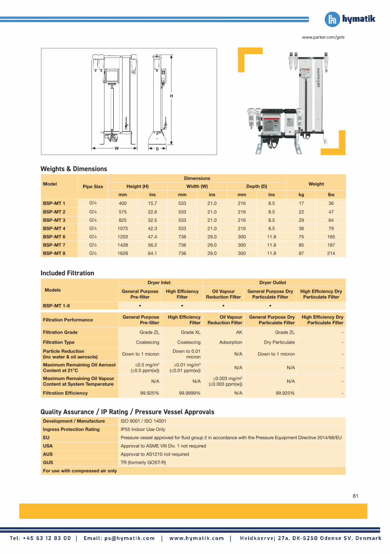
81
www.parker.com/gsfe
Model Pipe Size
DimensionsWeightHeight (H) Width (W) Depth (D)
mm ins mm ins mm ins kg lbs
BSP-MT 1 G¼ 400 15.7 533 21.0 216 8.5 17 36
BSP-MT 2 G¼ 575 22.6 533 21.0 216 8.5 22 47
BSP-MT 3 G¼ 825 32.5 533 21.0 216 8.5 29 64
BSP-MT 4 G¼ 1075 42.3 533 21.0 216 8.5 36 79
BSP-MT 6 G½ 1203 47.4 736 29.0 300 11.8 75 165
BSP-MT 7 G½ 1428 56.2 736 29.0 300 11.8 85 187
BSP-MT 8 G½ 1628 64.1 736 29.0 300 11.8 97 214
Models
Dryer Inlet Dryer Outlet
General Purpose Pre-filter
High Efficiency Filter
Oil Vapour Reduction Filter
General Purpose Dry Particulate Filter
High Efficiency Dry Particulate Filter
BSP-MT 1-8 • • • •
Filtration Performance General Purpose
Pre-filter High Efficiency
Filter Oil Vapour
Reduction Filter General Purpose Dry
Particulate FilterHigh Efficiency Dry
Particulate Filter
Filtration Grade Grade ZL Grade XL AK Grade ZL -
Filtration Type Coalescing Coalescing Adsorption Dry Particulate -
Particle Reduction (inc water & oil aerosols)
Down to 1 micron Down to 0.01
micronN/A Down to 1 micron -
Maximum Remaining Oil Aerosol Content at 21oC
≤0.5 mg/m3 (≤0.5 ppm(w))
≤0.01 mg/m3
(≤0.01 ppm(w)) N/A N/A -
Maximum Remaining Oil Vapour Content at System Temperature
N/A N/A≤0.003 mg/m3
(≤0.003 ppm(w)) N/A -
Filtration Efficiency 99.925% 99.9999% N/A 99.925% -
Weights & Dimensions
Included Filtration
Quality Assurance / IP Rating / Pressure Vessel Approvals
D
H
W
Development / Manufacture ISO 9001 / ISO 14001
Ingress Protection Rating IP55 Indoor Use Only
EU Pressure vessel approved for fluid group 2 in accordance with the Pressure Equipment Directive 2014/68/EU
USA Approval to ASME VIII Div. 1 not required
AUS Approval to AS1210 not required
GUS TR (formerly GOST-R)
For use with compressed air only

82
Compressed Breathing Air Purification
BSP-MT 10-95 Breathable Compressed Air Purifier
Product Selection & Correction FactorsFor correct operation, breathing air purifiers must be sized for the maximum (summer) inlet temperature, minimum inlet pressure and maximum flow rate of the installation.
To select a breathing air purifier, first calculate the MPC (Minimum Purification Capacity) using the formula below then select a breathing air purifier from the flow rate table above with a flow rate equal to or above the MPC. Minimum Purification Capacity = System Flow x Correction Factor
Models
Minimum Operating Pressure
Maximum Operating Pressure
Minimum Operating
Temperature
Maximum Operating
Temperature
Maximum Ambient
Temperature
Electrical Supply
(Standard)
Electrical Supply
(Option)
Thread Type
Noise Level
bar g psi g bar g psi g °C °F °C °F °C °F dB(A)
BSP-MT 10-95 5 73 16 232 5 41 50 122 50 122230V / 1ph / 50~60Hz
115V / 1ph / 50~60Hz
BSPP <75
ModelsDewpoint (Standard) ISO8573-1:2010 Classification
(Standard)°C °F
BSP-MT 10-95 -40 -40 Class 2.2.1
Model Pipe SizeFlow Rate Regeneration Air Requirement
L/s m3/min m3/hr cfm L/s m3/min m3/hr cfm
BSP-MT 10 G1 44 2.64 158 93 8.8 0.53 31.6 19
BSP-MT 15 G1 58 3.51 210 124 11.7 0.70 42 25
BSP-MT 20 G1 76 4.58 274 161 15.2 0.92 54.8 32
BSP-MT 25 G1½ 103 6.20 371 218 20.6 1.24 74.2 44
BSP-MT 35 G1½ 134 8.08 484 285 26.9 1.62 96.8 57
BSP-MT 45 G1½ 164 9.84 589 347 32.7 1.97 117.8 69
BSP-MT 60 G2 233 14.01 839 494 46.6 2.80 167.8 99
BSP-MT 75 G2 314 18.85 1129 665 62.7 3.77 225.8 133
BSP-MT 95 G2½ 381 22.90 1371 807 76.2 4.58 274.2 161
Stated flows are for operation at 13 bar (g) (189 psi g), 35°C (95°F) with reference to 20°C, 1 bar (a), 0% relative water vapour pressure. For flows at other conditions, apply the correction factors shown below.
Minimum Inlet Pressure bar g
(psi g)
Inlet temperature in °C (°F)
25 (77) 30 (86) 35 (95) 40 (104) 45 (113) 50 (122)
5 (73) 2.13 2.17 2.27 2.50 2.78 2.94
6 (87) 1.82 1.85 1.92 2.22 2.50 2.63
7 (102) 1.59 1.61 1.67 2.00 2.27 2.33
8 (116) 1.39 1.43 1.47 1.67 1.85 1.92
9 (131) 1.27 1.28 1.33 1.59 1.67 1.82
10 (145) 1.15 1.16 1.25 1.54 1.59 1.64
11 (160) 1.25 1.27 1.33 1.56 1.64 1.69
12 (174) 1.09 1.10 1.12 1.28 1.37 1.49
13 (189) 0.97 0.98 1.00 1.10 1.22 1.27
14 (203) 0.86 0.87 0.88 1.00 1.06 1.16
15 (218) 0.77 0.78 0.79 0.93 0.97 1.01
Dryer Performance
Technical Data
Flow Rates
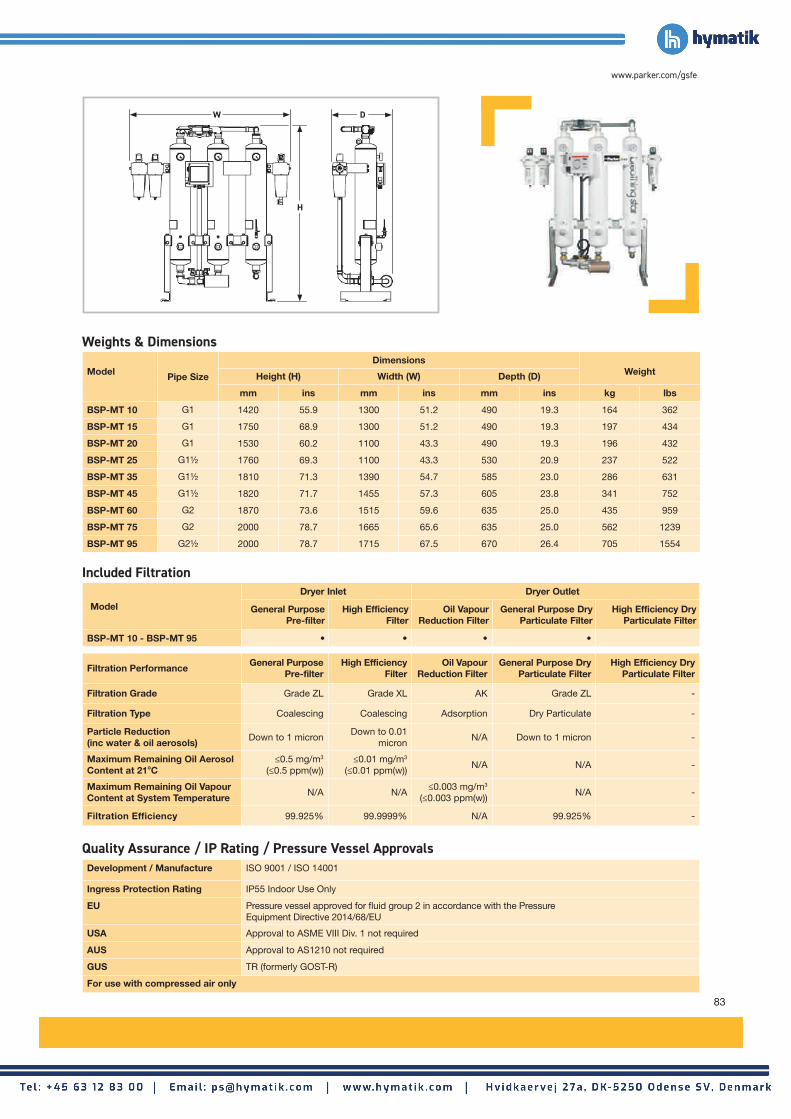
83
www.parker.com/gsfe
Model
Dryer Inlet Dryer Outlet
General Purpose Pre-filter
High Efficiency Filter
Oil Vapour Reduction Filter
General Purpose Dry Particulate Filter
High Efficiency Dry Particulate Filter
BSP-MT 10 - BSP-MT 95 • • • •
Model Pipe Size
DimensionsWeightHeight (H) Width (W) Depth (D)
mm ins mm ins mm ins kg lbs
BSP-MT 10 G1 1420 55.9 1300 51.2 490 19.3 164 362
BSP-MT 15 G1 1750 68.9 1300 51.2 490 19.3 197 434
BSP-MT 20 G1 1530 60.2 1100 43.3 490 19.3 196 432
BSP-MT 25 G1½ 1760 69.3 1100 43.3 530 20.9 237 522
BSP-MT 35 G1½ 1810 71.3 1390 54.7 585 23.0 286 631
BSP-MT 45 G1½ 1820 71.7 1455 57.3 605 23.8 341 752
BSP-MT 60 G2 1870 73.6 1515 59.6 635 25.0 435 959
BSP-MT 75 G2 2000 78.7 1665 65.6 635 25.0 562 1239
BSP-MT 95 G2½ 2000 78.7 1715 67.5 670 26.4 705 1554
Filtration Performance General Purpose
Pre-filter High Efficiency
Filter Oil Vapour
Reduction Filter General Purpose Dry
Particulate FilterHigh Efficiency Dry
Particulate Filter
Filtration Grade Grade ZL Grade XL AK Grade ZL -
Filtration Type Coalescing Coalescing Adsorption Dry Particulate -
Particle Reduction (inc water & oil aerosols)
Down to 1 micron Down to 0.01
micronN/A Down to 1 micron -
Maximum Remaining Oil Aerosol Content at 21oC
≤0.5 mg/m3 (≤0.5 ppm(w))
≤0.01 mg/m3
(≤0.01 ppm(w)) N/A N/A -
Maximum Remaining Oil Vapour Content at System Temperature
N/A N/A≤0.003 mg/m3
(≤0.003 ppm(w)) N/A -
Filtration Efficiency 99.925% 99.9999% N/A 99.925% -
Development / Manufacture ISO 9001 / ISO 14001
Ingress Protection Rating IP55 Indoor Use Only
EU Pressure vessel approved for fluid group 2 in accordance with the Pressure Equipment Directive 2014/68/EU
USA Approval to ASME VIII Div. 1 not required
AUS Approval to AS1210 not required
GUS TR (formerly GOST-R)
For use with compressed air only
Weights & Dimensions
Included Filtration
Quality Assurance / IP Rating / Pressure Vessel Approvals
D
H
W

84
Compressed Breathing Air Purification
BAM 10-70 Breathable Compressed Air Purifier
Maximum Inlet Temperature
°C 25 30
°F 77 86
Correction Factor 1.00 1.20
Minimum Inlet Pressure
bar g 4 5 6 7 8 9 10 11 12 13
psi g 58 73 87 100 116 131 145 160 174 189
Correction Factor 1.60 1.33 1.14 1.00 0.89 0.80 0.73 0.67 0.62 0.57
Product Selection & Correction FactorsFor correct operation, breathing air purifiers must be sized using for the maximum (summer) inlet temperature, minimum inlet pressure and maximum flow rate of the installation.
To select a breathing air purifier, first calculate the MPC (Minimum Purification Capacity) using the formula below then select a breathing air purifier from the flow rate table above with a flow rate equal to or above the MPC. Minimum Purification Capacity = System Flow x CFMIT x CFMIP
Models
Minimum Operating Pressure
Maximum Operating Pressure
Minimum Operating
Temperature
Maximum Operating
Temperature
Maximum Ambient
Temperature
Electrical Supply
(Standard)
Thread Type
Noise Level
bar g psi g bar g psi g °C °F °C °F °C °F dB(A)
BAM10 - BAM70 4 58 13 190 5 41 30 86 55 13185 - 265V
1ph 50/60HzBSPP or
NPT <75
ModelsDewpoint (Standard) ISO8573-1:2010 Classification
(Standard)°C °F
BAM -40 -40 Class 1.2.1
Model Pipe SizeInlet Flow Rate Regeneration Air Requirement
L/s m3/min m3/hr cfm L/s m3/min m3/hr cfm
BAM10 G2 113 6.81 408 240 22.6 1.36 82 48
BAM20 G2 170 10.22 612 360 34.0 2.04 122 72
BAM30 G2 213 12.78 795 450 42.6 2.60 159 90
BAM40 G2 283 17 1020 600 56.6 3.40 204 120
BAM50 G2½ 354 21 1275 750 70.8 4.20 255 150
BAM70 G2½ 496 30 1785 1050 99.2 6.00 357 210
Stated flows are for operation at 7 bar (g) (102 psi g) with reference to 20°C, 1 bar (a), 0% relative water vapour pressure. For flows at other conditions, apply the correction factors shown below.
CFIT - Correction Factor Maximum Inlet Temperature
CFMIP - Correction Factor Minimum Inlet Pressure
Dryer Performance
Technical Data
Flow Rates

85
www.parker.com/gsfe
ModelsPipe Size
BSPP or NPT
Dryer Inlet Dryer Outlet
General Purpose Pre-filter
High Efficiency Filter
Oil Vapour Reduction Filter
General Purpose Dry Particulate Filter
High Efficiency Dry Particulate Filter
BAM10 - BAM70 G2 • • • • •
Model Pipe SizeBSPP
DimensionsWeightHeight (H) Width (W) Depth (D)
mm ins mm ins mm ins kg lbs
BAM10 G2 1797 70.7 1260 49.6 1655 65.2 600 1322
BAM20 G2 1797 70.7 1260 49.6 1655 65.2 700 1543
BAM30 G2 2042 80.4 1260 49.6 1655 65.2 800 1763
BAM40 G2½ 2042 80.4 1260 49.6 1655 65.2 900 1984
BAM50 G2½ 2042 80.4 1260 49.6 1950 76.8 1100 2425
BAM70 G2½ 2042 80.4 1260 49.6 1950 76.8 1400 3086
Filtration Performance General Purpose
Pre-filter High Efficiency
Filter Oil Vapour
Reduction Filter
General Purpose Dry Particulate
Filter
High Efficiency Dry Particulate
Filter
Filtration Grade Grade AO Grade AA OVR Grade AO Grade AA
Filtration Type Coalescing Coalescing Adsorption Dry Particulate Coalescing
Particle Reduction (inc water & oil aerosols)
Down to 1 micron Down to 0.01
micronN/A Down to 1 micron
Down to 0.01 micron
Maximum Remaining Oil Aerosol Content at 21oC
≤0.5 mg/m3 (≤0.5 ppm(w))
≤0.01 mg/m3
(≤0.01 ppm(w)) N/A N/A N/A
Maximum Remaining Oil Vapour Content at System Temperature
N/A N/A≤0.003 mg/m3
(≤0.003 ppm(w)) N/A N/A
Filtration Efficiency 99.925% 99.9999% N/A 99.925% 99.9999%
Weights & Dimensions
Included Filtration
Quality Assurance / IP Rating / Pressure Vessel Approvals
D
H
W
Development / Manufacture ISO 9001 / ISO 14001
Ingress Protection Rating IP55 Indoor Use Only
EU Pressure vessel approved for fluid group 2 in accordance with the Pressure Equipment Directive 2014/68/EU
USA Approval to ASME VIII Div. 1 not required
AUS Approval to AS1210 not required
GUS TR (formerly GOST-R)
For use with compressed air only

86
Product SelectionCorrect selection is critical for the operation of oil/water separators. Increased condensate flow through an oil/water separator reduces settlement time in the main tank, increases oil carryover to the carbon stage & reduces contact time with the carbon. The overall effect of incorrect sizing is poor outlet water quality, reduced carbon filter life and the potential for overflowing.
Capacities shown in this catalogue assume installation in two of the worlds major climatic conditions. Should the oil/water separator be installed in conditions other than those shown, please contact your local Parker outlet or approved distributor/agent for correct sizing.
Oil Types
To simplify the selection, lubricant classifications have been split into three bands depending upon their ability to separate within a static type oil/water separator.
Band A: Turbine Oil, Additive Free Oil
Band B: Mineral
Poly alpha olefins (PAO)
Trimethylolpropane Ester (TMP),
Pentaerythrityl Ester (PE)
Band C: Diesters, Triesters,
Polyoxyalkylene glycol (PAG)
Inseparable using static Separation
Techniques: Automatic transmission fluid (ATF)
Drain Types
The condensate should be removed from the compressed air system using a drainage method that does not cause emulsification of the condensate and is appropriate for the unit. Usual methods include :
• Level Operated Electronic Drain
• Float Drain
• Timed Solenoid Drain*
Parker recommends the use of the ED3000 Series range of condensate drains. Manual and Thermodynamic Disc trap drains must not be used with the ES2000 Series oil/water separators.
*If the use of timed solenoid drains is unavoidable, steps must be taken to reduce the air loss as this has an emulsifying effect on the condensate.
Refrigeration Dryers
A refrigeration dryer installed in a compressed air system can significantly increase the condensate produced. The oil/water separator must be sized appropriately to treat the extra condensate produced. Flow capacities within this literature are shown both with and without a refrigeration dryer installed.
Important Note:
Additives blended into the lubricants to prevent bacterial growth, rusting, corrosion, and to promote emulsification, such as detergents etc., can have an impact on the separating process. Static oil/water separators are unable to separate stable emulsions or oils that are miscible in water. Additionally, these units will not totally separate lubricants containing: Emulsifying
Agents; Glycol additives; or Polyglycol based coolants.
ES2000 Series Oil / Water Separators
Condensate Management

87
www.parker.com/gsfe
Climate Condition 1 - Outlet quality: <20mg/l oil in water
Climate Condition 2 - Outlet quality: <20mg/l oil in water
For systems using 1 or 2 stage piston/reciprocating compressors multiply compressor flow by 1.4 and select a separator from screw compressor flow rates shown, ensuring due consideration is given to oil type. For sizing at conditions other than those shown, please contact Parker for correct product selection.
No Refrigeration Dryer Installed in System
Oil TypeBand A
Turbine, Additive FreeBand B
Mineral, PAO, TMP, PEBand C
Diesters, Triesters, PAGCompressor Type Model L/s m3/min m3/hr cfm L/s m3/min m3/hr cfm L/s m3/min m3/hr cfm
Rotary Screw, Vane
ES2100 36.9 2.2 133 78 30.8 1.9 111 66 25.6 1.5 92 54ES2150 58.6 3.5 211 124 50.0 3 180 106 40.6 2.4 146 86ES2200 90.3 5.4 325 191 76.7 4.6 276 163 62.5 3.7 225 132ES2300 126.7 7.6 456 268 106.4 6.4 383 225 87.5 5.3 315 185ES2400 253.4 15.2 912 537 212.8 12.8 766 451 175.0 10.5 630 371ES2500 501.4 30.1 1805 1062 425.0 25.5 1530 900 346.4 20.8 1247 734ES2600 997.6 59.9 3591 2114 849.2 51 3057 1800 689.5 41.4 2482 1461
Refrigeration Dryer Installed in System
Oil TypeBand A
Turbine, Additive FreeBand B
Mineral, PAO, TMP, PEBand C
Diesters, Triesters, PAGCompressor Type Model L/s m3/min m3/hr cfm L/s m3/min m3/hr cfm L/s m3/min m3/hr cfm
Rotary Screw, Vane
ES2100 27.8 1.7 100 59 23.3 1.4 84 49 19.2 1.2 69 41ES2150 43.9 2.6 158 93 37.5 2.3 135 80 30.6 1.8 110 65ES2200 67.8 4.1 244 144 57.8 3.5 208 122 46.9 2.8 169 99ES2300 95.3 5.7 343 202 80.0 4.8 288 169 65.8 3.9 237 139ES2400 190.3 11.4 685 403 159.7 9.6 575 339 131.7 7.9 474 279ES2500 377.0 22.6 1357 798 319.2 19.2 1149 677 260.6 15.6 938 552ES2600 749.8 45 2699 1589 638.4 38.3 2298 1352 518.1 31.1 1865 1098
System ConditionsAmbient Temperature at Compressor Inlet: 25°C (77°F) Refrigeration Dryer Dewpoint If Fitted: 3°C Relative Humidity: 65% Minimum System Temperature If Refrigeration Dryer Is Not Fitted: 30°C (86°F)Compressor Discharge Temperature: 35°C (95°F) System Pressure: 7 bar g (102 psi g) Outlet quality: <20mg/l oil in water
No Refrigeration Dryer Installed in System
Oil TypeBand A
Turbine, Additive FreeBand B
Mineral, PAO, TMP, PEBand C
Diesters, Triesters, PAGCompressor Type Model L/s m3/min m3/hr cfm L/s m3/min m3/hr cfm L/s m3/min m3/hr cfm
Rotary Screw, Vane
ES2100 13.9 0.8 50 30 11.7 0.7 42 25 9.7 0.6 35 21ES2150 22.2 1.3 80 47 18.9 1.1 68 40 15.6 0.9 56 33ES2200 34.2 2.1 123 73 29.2 1.7 105 62 23.6 1.4 85 50ES2300 48.1 2.9 173 102 40.3 2.4 145 85 33.1 2 119 70ES2400 96.1 5.8 346 204 80.6 4.8 290 171 66.4 4 239 141ES2500 190.0 11.4 684 403 161.1 9.7 580 341 131.4 7.9 473 278ES2600 378.4 22.7 1362 801 322.0 19.3 1159 682 261.4 15.7 941 554
Refrigeration Dryer Installed in System
Oil TypeBand A
Turbine, Additive FreeBand B
Mineral, PAO, TMP, PEBand C
Diesters, Triesters, PAGCompressor Type Model L/s m3/min m3/hr cfm L/s m3/min m3/hr cfm L/s m3/min m3/hr cfm
Rotary Screw, Vane
ES2100 11.4 0.7 41 24 9.4 0.6 34 20 7.8 0.5 28 17ES2150 17.8 1.1 64 38 15.3 0.9 55 32 12.5 0.7 45 26ES2200 27.5 1.7 99 59 23.6 1.4 85 50 19.2 1.1 69 40ES2300 38.9 2.3 140 82 32.5 2 117 69 26.7 1.6 96 57ES2400 77.5 4.7 279 164 65.0 3.9 234 138 53.6 3.2 193 114ES2500 153.3 9.2 552 325 130.0 7.8 468 275 106.1 6.4 382 225ES2600 305.3 18.3 1099 647 260.0 15.6 936 551 210.9 12.7 759 447
System ConditionsAmbient Temperature at Compressor Inlet: 35°C (95°F) Refrigeration Dryer Dewpoint If Fitted: 3°C Relative Humidity: 85% Minimum System Temperature If Refrigeration Dryer Is Not Fitted: 40°C (104°F)Compressor Discharge Temperature: 45°C (113°F) System Pressure: 7 bar g (102 psi g) Outlet quality: <20mg/l oil in water

88
Climate Condition 1 - Outlet quality: <10mg/l oil in water
Climate Condition 2 - Outlet quality: <10mg/l oil in water
For systems using 1 or 2 stage piston/reciprocating compressors multiply compressor flow by 1.4 and select a separator from screw compressor flow rates shown, ensuring due consideration is given to oil type. For sizing at conditions other than those shown, please contact Parker for correct product selection.
No Refrigeration Dryer Installed in System
Oil TypeBand A
Turbine, Additive FreeBand B
Mineral, PAO, TMP, PEBand C
Diesters, Triesters, PAGCompressor Type Model L/s m3/min m3/hr cfm L/s m3/min m3/hr cfm L/s m3/min m3/hr cfm
Rotary Screw, Vane
ES2100 20.6 1.2 74 43 17.2 1 62 36 14.2 0.9 51 30ES2150 32.5 2 117 69 27.8 1.7 100 59 22.5 1.4 81 48ES2200 50.3 3 181 106 42.5 2.6 153 90 34.7 2.1 125 73ES2300 70.3 4.2 253 149 59.2 3.5 213 125 48.6 2.9 175 103ES2400 140.8 8.4 507 298 118.1 7.1 425 250 97.2 5.8 350 206ES2500 278.6 16.7 1003 590 236.1 14.2 850 500 192.5 11.6 693 408ES2600 554.2 33.3 1995 1174 472.0 28.3 1699 1000 383.1 23 1379 812
Refrigeration Dryer Installed in System
Oil TypeBand A
Turbine, Additive FreeBand B
Mineral, PAO, TMP, PEBand C
Diesters, Triesters, PAGCompressor Type Model L/s m3/min m3/hr cfm L/s m3/min m3/hr cfm L/s m3/min m3/hr cfm
Rotary Screw, Vane
ES2100 15.6 0.9 56 33 13.1 0.8 47 27 10.6 0.6 38 23ES2150 24.4 1.5 88 52 20.8 1.3 75 44 16.9 1 61 36ES2200 37.8 2.3 136 80 31.9 1.9 115 68 26.1 1.6 94 55ES2300 52.8 3.2 190 112 44.4 2.7 160 94 36.7 2.2 132 77ES2400 105.8 6.3 381 224 88.9 5.3 320 188 73.1 4.4 263 155ES2500 209.5 12.6 754 444 177.5 10.6 639 376 144.7 8.7 521 307ES2600 416.4 25 1499 883 354.8 21.3 1277 751 287.8 17.3 1036 610
System ConditionsAmbient Temperature at Compressor Inlet: 25°C (77°F) Refrigeration Dryer Dewpoint If Fitted: 3°C Relative Humidity: 65% Minimum System Temperature If Refrigeration Dryer Is Not Fitted: 30°C (86°F)Compressor Discharge Temperature: 35°C (95°F) System Pressure: 7 bar g (102 psi g) Outlet quality: <10mg/l oil in water
No Refrigeration Dryer Installed in System
Oil TypeBand A
Turbine, Additive FreeBand B
Mineral, PAO, TMP, PEBand C
Diesters, Triesters, PAGCompressor Type Model L/s m3/min m3/hr cfm L/s m3/min m3/hr cfm L/s m3/min m3/hr cfm
Rotary Screw, Vane
ES2100 7.8 0.5 28 16 6.4 0.4 23 14 5.3 0.3 19 11ES2150 12.2 0.7 44 26 10.6 0.6 38 22 8.6 0.5 31 18ES2200 18.9 1.1 68 40 16.1 1 58 34 13.1 0.8 47 28ES2300 26.7 1.6 96 57 22.5 1.3 81 47 18.3 1.1 66 39ES2400 53.3 3.2 192 113 44.7 2.7 161 95 36.9 2.2 133 78ES2500 105.6 6.3 380 224 89.5 5.4 322 190 73.1 4.4 263 155ES2600 210.0 12.6 756 445 178.9 10.7 644 379 145.3 8.7 523 308
Refrigeration Dryer Installed in System
Oil TypeBand A
Turbine, Additive FreeBand B
Mineral, PAO, TMP, PEBand C
Diesters, Triesters, PAGCompressor Type Model L/s m3/min m3/hr cfm L/s m3/min m3/hr cfm L/s m3/min m3/hr cfm
Rotary Screw, Vane
ES2100 6.4 0.4 23 13 5.3 0.3 19 11 4.4 0.3 16 9ES2150 10.0 0.6 36 21 8.6 0.5 31 18 6.9 0.4 25 15ES2200 15.3 0.9 55 33 13.1 0.8 47 28 10.6 0.6 38 22ES2300 21.7 1.3 78 46 18.1 1.1 65 38 15.0 0.9 54 32ES2400 43.1 2.6 155 91 36.1 2.2 130 77 29.7 1.8 107 63ES2500 85.3 5.1 307 181 72.2 4.3 260 153 58.9 3.5 212 125ES2600 169.7 10.2 611 359 144.5 8.7 520 306 117.2 7 422 248
System ConditionsAmbient Temperature at Compressor Inlet: 35°C (95°F) Refrigeration Dryer Dewpoint If Fitted: 3°C Relative Humidity: 85% Minimum System Temperature If Refrigeration Dryer Is Not Fitted: 40°C (104°F)Compressor Discharge Temperature: 45°C (113°F) System Pressure: 7 bar g (102 psi g) Outlet quality: <10mg/l oil in water
Condensate Management

89
www.parker.com/gsfe
Climate Condition 1 - Outlet quality: <5mg/l oil in water
Climate Condition 2 - Outlet quality: <5mg/l oil in water
For systems using 1 or 2 stage piston/reciprocating compressors multiply compressor flow by 1.4 and select a separator from screw compressor flow rates shown, ensuring due consideration is given to oil type. For sizing at conditions other than those shown, please contact Parker for correct product selection.
No Refrigeration Dryer Installed in System
Oil TypeBand A
Turbine, Additive FreeBand B
Mineral, PAO, TMP, PEBand C
Diesters, Triesters, PAGCompressor Type Model L/s m3/min m3/hr cfm L/s m3/min m3/hr cfm L/s m3/min m3/hr cfm
Rotary Screw, Vane
ES2100 10.3 0.6 37 22 8.6 0.5 31 18 7.2 0.4 26 15ES2150 16.4 1 59 34 13.9 0.8 50 29 11.4 0.7 41 24ES2200 25.0 1.5 90 53 21.4 1.3 77 45 17.2 1 62 37ES2300 35.3 2.1 127 75 29.4 1.8 106 63 24.4 1.5 88 52ES2400 70.3 4.2 253 149 59.2 3.5 213 125 48.6 2.9 175 103ES2500 139.2 8.4 501 295 118.1 7.1 425 250 96.4 5.8 347 204ES2600 277.2 16.6 998 587 235.9 14.2 849 500 191.4 11.5 689 406
Refrigeration Dryer Installed in System
Oil TypeBand A
Turbine, Additive FreeBand B
Mineral, PAO, TMP, PEBand C
Diesters, Triesters, PAGCompressor Type Model L/s m3/min m3/hr cfm L/s m3/min m3/hr cfm L/s m3/min m3/hr cfm
Rotary Screw, Vane
ES2100 7.8 0.5 28 16 6.4 0.4 23 14 5.3 0.3 19 11ES2150 12.2 0.7 44 26 10.6 0.6 38 22 8.6 0.5 31 18ES2200 18.9 1.1 68 40 16.1 1 58 34 13.1 0.8 47 28ES2300 26.4 1.6 95 56 22.2 1.3 80 47 18.3 1.1 66 39ES2400 52.8 3.2 190 112 44.4 2.7 160 94 36.7 2.2 132 77ES2500 104.7 6.3 377 222 88.6 5.3 319 188 72.2 4.3 260 153ES2600 208.4 12.5 750 441 177.2 10.6 638 376 143.9 8.6 518 305
System ConditionsAmbient Temperature at Compressor Inlet: 25°C (77°F) Refrigeration Dryer Dewpoint If Fitted: 3°C Relative Humidity: 65% Minimum System Temperature If Refrigeration Dryer Is Not Fitted: 30°C (86°F)Compressor Discharge Temperature: 35°C (95°F) System Pressure: 7 bar g (102 psi g) Outlet quality: <5mg/l oil in water
No Refrigeration Dryer Installed in System
Oil TypeBand A
Turbine, Additive FreeBand B
Mineral, PAO, TMP, PEBand C
Diesters, Triesters, PAGCompressor Type Model L/s m3/min m3/hr cfm L/s m3/min m3/hr cfm L/s m3/min m3/hr cfm
Rotary Screw, Vane
ES2100 3.9 0.2 14 8 3.3 0.2 12 7 2.8 0.2 10 6ES2150 6.1 0.4 22 13 5.3 0.3 19 11 4.2 0.3 15 9ES2200 9.4 0.6 34 20 8.1 0.5 29 17 6.7 0.4 24 14ES2300 13.3 0.8 48 28 11.1 0.7 40 24 9.2 0.6 33 20ES2400 26.7 1.6 96 57 22.5 1.3 81 47 18.3 1.1 66 39ES2500 52.8 3.2 190 112 44.7 2.7 161 95 36.4 2.2 131 77ES2600 105.0 6.3 378 223 89.5 5.4 322 190 72.5 4.4 261 154
Refrigeration Dryer Installed in System
Oil TypeBand A
Turbine, Additive FreeBand B
Mineral, PAO, TMP, PEBand C
Diesters, Triesters, PAGCompressor Type Model L/s m3/min m3/hr cfm L/s m3/min m3/hr cfm L/s m3/min m3/hr cfm
Rotary Screw, Vane
ES2100 3.1 0.2 11 7 2.5 0.2 9 6 2.2 0.1 8 5ES2150 5.0 0.3 18 11 4.2 0.3 15 9 3.3 0.2 12 7ES2200 7.8 0.5 28 16 6.4 0.4 23 14 5.3 0.3 19 11ES2300 10.8 0.6 39 23 9.2 0.5 33 19 7.5 0.4 27 16ES2400 21.7 1.3 78 46 18.1 1.1 65 38 15.0 0.9 54 32ES2500 42.5 2.6 153 90 36.1 2.2 130 77 29.4 1.8 106 62ES2600 84.7 5.1 305 180 72.2 4.3 260 153 58.6 3.5 211 124
System ConditionsAmbient Temperature at Compressor Inlet: 35°C (95°F) Refrigeration Dryer Dewpoint If Fitted: 3°C Relative Humidity: 85% Minimum System Temperature If Refrigeration Dryer Is Not Fitted: 40°C (104°F)Compressor Discharge Temperature: 45°C (113°F) System Pressure: 7 bar g (102 psi g) Outlet quality: <5mg/l oil in water

90
Separator ModelsSeparator
TypeResidual Oil in Water Content (Outlet)
ServicePeriod
ES2100 - ES2600 Static
Each Separator model is sizeable to deliver a residual oil in water level of: When oil in water levels
exceed allowed levels
<20mg/L<10mg/L <5mg/L
Separator Performance
Model ES2100 ES2150 ES2200 ES2300 ES2400 ES2500 ES2600
Inlet Connections 1 x 1/2" 1 x 1/4"
1 x 1/2" 1 x 1/4"
1 x 1/2" 1 x 1/4"
1 x 1/2" 3 x 1/4"
1 x 1/2" 3 x 1/4"
1 x 1/2" 3 x 1/4"
1 x 1/2" 3 x 1/4"
Outlet Hose Connections 19mm (3/4") 25mm (1") 19mm (3/4") 25mm (1") 25mm (1") 25mm (1") 25mm (1")
Settlement Tank CapacityN/A 60 litres 75 litres 125 litres 185 litres 355 litres 485 litres
N/A 16 US G 20 US G 33 US G 49 US G 94 US G 128 US G
Max. Pressure 16 bar g (232 psi g)
Min/ Max Temperature
°C 5 to 35 5 to 35 5 to 35 5 to 35 5 to 35 5 to 35 5 to 35
°F 41 to 95 41 to 95 41 to 95 41 to 95 41 to 95 41 to 95 41 to 95
Material (Re-cyclable) Polyethylene
ES2000 Series Oil / Water Separators
Condensate Management
Technical Data

91
www.parker.com/gsfe
ModelHeight (H) Width (W) Depth (D)
WeightEmpty Full
mm ins mm ins mm ins kg lbs kg lbs
ES2100 842 33.1 250 9.8 315 12.4 6 13 24.5 154
ES2150 810 31.9 350 13.8 430 16.9 10 22 78.5 173
ES2200 805 31.7 350 13.8 450 17.7 12 26 93.5 206
ES2300 1195 47.0 500 19.7 800 31.5 27 59 159 350
ES2400 1195 47.0 650 26.6 800 31.5 36 79 217 477
ES2500 1535 60.4 700 27.6 985 38.8 70 154 400 880
ES2600 1535 60.4 1000 39.4 1010 39.8 97 214 550 1210
Weights and Dimensions
ES2150 to ES2600ES2100
W
H
D
H
D W
Parker Catalogue Numbers
Model Catalogue Number
ES2100 ES2100-TI
ES2150 ES2150-TI
ES2200 ES2200-TI
ES2300 ES2300-TI
ES2400 ES2400-TI
ES2500 ES2500-TI
ES2600 ES2600-TI
Maintenance Kits
Model Quantity Required Part Number
ES2100-TI 1 ESMK1
ES2150-TI 1 ESMK1
ES2200-TI 1 ESMK1
ES2300-TI 1 ESMK2
ES2400-TI 2 ESMK2
ES2500-TI 1 ESMK3
ES2600-TI 2 ESMK3
Service Kits - Vent Filter
Model Part Number
ES2100-TI ESVF1
ES2150-TI ESVF1
ES2200-TI ESVF1
ES2300-TI ESVF2
ES2400-TI ESVF2
ES2500-TI ESVF2
ES2600-TI ESVF2

92
Drain Type Drain ModelsMinimum
Operating PressureMaximum
Operating PressureMinimum
Operating TemperatureMaximum
Operating Temperature
bar g psi g bar g psi g ºC ºF ºC ºF
External Float HDF120 - 220 1 15 16 232 2 35 60 140
Electronic Level Sensing ED3002 - ED3100 1 15 16 232 2 35 60 140
Electronic Level Sensing ED4100 16 232 50 725 2 35 50 122
Stated flows are for operation at max operating pressure shown above, ambient air 25°C (77°F) / 60% RH, compressor discharge temperature 35°C (95°F), refrigeration dryer pressure dewpoint +3°C, with reference to 20°C, 1 bar (a), 0% relative water vapour pressure. . Refrgeration dryer and filter flow rates assume adequate condensate drainge upstream.
Flow Rates - Zero Air Loss External Float Drains
ModelPipe Size
Compressed Air Flow Rate Electrical Supply
Inlet Outlet L/S m³/min m³/hr cfm
HDF120-A 1/2" 1/2" 1500 90 5400 3178 -
HDF180-A 1" 1/2" 1667 100 6000 3532 -
HDF220-A 1" 1/2" 4167 251 15000 8829 -
External float drain (with built-in air vent)
HDF120 1/2" 1/2" 1500 90 5400 3178 -
HDF180 1" 1/2" 1667 100 6000 3532 -
HDF220 1" 1/2" 4167 251 15000 8829 -
External float drain (without air vent)
HDF220BE 1" 1/2" 1806 109 6500 3826 -
External float drains BioEnergy
Technical Data
ModelPipe Size
Compressed Air Flow Rate(Aftercooler / Air Receiver)
Compressed Air Flow Rate(Refrigeration Dryer)
Compressed Air Flow Rate(Filter) Electrical
SupplyInlet Outlet L/S m³/min m³/hr cfm L/S m³/min m³/hr cfm L/S m³/min m³/hr cfm
ED3002-G230 1 x G1/2 G3/8 - - - - - - - - 200 12 720 424 230/1/50-60
ED3004-G230 1 x G1/2 G3/8 67 4 240 141 133 8 480 283 667 40 2400 1413 230/1/50-60
ED3007-G230 2 x G1/2 G3/8 117 7 420 247 233 14 840 494 1167 70 4200 2472 230/1/50-60
ED3030-G230 2 x G1/2 G3/8 500 30 1800 1059 1000 60 3600 2119 5000 301 18000 10595 230/1/50-60
ED3100-G230 2 x G1/2 G3/8 1667 100 6000 3532 3334 200 12000 7063 16668 1002 60000 35316 230/1/50-60
230V/1PH/50-60Hz - 16 bar g (232 psi g)
ED3007-G24D 2 x G1/2 G3/8 117 7 420 247 233 14 840 494 1167 70 4200 2472 24V DC
ED3030-G24D 2 x G1/2 G3/8 500 30 1800 1059 1000 60 3600 2119 5000 301 18000 10595 24V DC
ED3100-G24D 2 x G1/2 G3/8 1667 100 6000 3532 3334 200 12000 7063 16668 1002 60000 35316 24V DC
24V DC - 16 bar g (232 psi g)
ED4100/50-G230 G1/2 G1/4 1667 100 6000 3532 3334 200 12000 7063 16668 1002 60000 35316 230/1/50-60
230V/1PH/50-60Hz - 50 bar g (725 psi g)
ED4100/50-G24D G1/2 G1/4 1667 100 6000 3532 3334 200 12000 7063 16668 1002 60000 35316 24V DC
24V DC - 50 bar g (725 psi g)
Flow Rates - Zero Air Loss Electronic Level Sensing Drains
HDF & ED Level Sensing Condensate Drains
Condensate Management

93
www.parker.com/gsfe
ModelHeight (H) Width (W) Depth (D) Weight
mm ins mm ins mm ins kg lbs
HDF120 111 4.4 156 6.1 108 4.3 0.9 2.0
HDF180 111 4.4 156 6.1 108 4.3 0.9 2.0
HDF220 111 4.4 266 10.5 108 4.3 1.9 4.2
HDF220BE 111 4.4 266 10.5 108 4.3 1.9 4.2
ED3002 146 5.7 110 4.3 67 2.6 0.5 1.1
ED3004 139 5.5 101 4.0 67 2.6 0.6 1.3
ED3007 164 6.5 122 4.8 67 2.6 1 2.2
ED3030 164 6.5 137 5.4 67 2.6 1 2.2
ED3100 164 6.5 197 7.8 67 2.6 2 4.4
ED4100 115 4.5 178 7.0 87 3.4 1.9 4.2
Weight & Dimensions
HDF 120 - 180 ED 3002 - 4100
HDF 220
ModelCatalogue Number
230V, 50-60 Hz / 16 bar gCatalogue Number24V DC / 16 bar g
ED3002 ED3002-G230 -
ED3004 ED3004-G230 -
ED3007 ED3007-G230 ED3007-G24D
ED3030 ED3030-G230 ED3030-G24D
ED3100 ED3100-G230 ED3100-G24D
ModelCatalogue Number
BSPP / 16 bar gCatalogue Number
BSPP/ 16 bar g + VentCatalogue Number
NPT / 16 bar g + Vent
HDF120 HDF120 HDF120A HDF120NPTA
HDF180 HDF180 HDF180A HDF180NPTA
HDF220 HDF220 HDF220A HDF220NPTA
Parker Catalogue Numbers (ED Drains)
Parker Catalogue Numbers (HDF Drains)
H
D
W
H
W D
H
W D

94
Hypercool Air and Water Cooled Aftercoolers
Thermal and Power Management
Technical Data - Hypercool Air Cooled
ModelFlow Rate Maximum
Operating Pressure Pipe Conn.
ElectricalSupply
AdsorbedCurrent
Pressure dropat nominalconditions
Noise Level
at 10 m
m³/h m³/min bar g psi g (V/ph/Hz) (A) (kPa) dB(A)
ADS004 210 3.5 16 232 1½" 230/1/50 0.36 14 44.1
ADT006 360 6 16 232 1½" 400/3/50 0.29 22 54.2
ADT009 540 9 16 232 2" 400/3/50 0.52 13 58.5
ADT028 1680 28 16 232 DN 80 400/3/50 2.70 15 70.3
ADT038 2160 36 16 232 DN 100 400/3/50 2.70 16 70.3
ADT064 3840 64 16 232 DN 150 400/3/50 5.40 26 73.0
Technical Data - Hypercool Water Cooled
ModelFlow Rate Maximum
Operating PressurePipe
Conn.
m³/h m³/min bar g psi g Air Water
Standard VersionWFN009 540 9 16 232 2" ¾"
WFN027 1620 27 12 174 DN100 1¼"
WFN050 3000 50 12 174 DN125 1¼"
WFN090 5400 90 12 174 DN200 1¼"
Removable Tube-BundleWRN007 420 7 16 232 DN 50 ½"
WRN016 960 16 16 232 DN 80 ¾"
WRN028 1680 28 12 174 DN 100 1"
WRN050 3000 50 12 174 DN 125 1¼"
WRN090 5400 90 12 174 DN 200 1¼"
WRN130 7800 130 10 145 DN 250 1½"
WRN170 10200 170 10 145 DN 300 2"
WRN250 15000 250 10 145 DN 350 DN 65
WRN350 21000 350 10 145 DN 450 DN 80
WRN450 27000 450 10 145 DN 500 DN 100
WRN550 33000 550 10 145 DN 600 DN 100
Performances refer to models in standard materials, operating with clean cooler, with air at FAD 20°C / 1 bar A, and at the following working conditions: air suction 25°C/60 % RH, 7 bar g working pressure, 120°C compressed air inlet temperature, temperature approach between air outlet and cooling air of ca. 10°C. The performance of models with non standard materials may differ from those quoted above.
Performances refer to clean cooler conditions with air at FAD 20°C / 1 bar A, and at the following working conditions: air suction 25°C / 60%RH, 7 bar g working pressure, 120°C compressed air inlet temperature, temperature approach between air outlet and water inlet of ca. 10°C. Maximum air inlet temperature: 200°C (for higher temperatures and other gases contact Parker Sales Companies).

95
www.parker.com/gsfe
ADS0004 / ADT006-009
Weights and Dimensions - Hypercool Air Cooled
ModelHeight (H) Width (W) Width (W1) Depth Weight
mm ins mm ins mm ins mm ins kg lbs
ADS004 1140 44.9 715 28.1 550 21.7 303 11.9 37 81
ADT006 1315 51.8 855 33.7 690 27.2 455 17.9 58 128
ADT009 1315 51.8 1173 46.2 936 36.9 480 18.9 70 154
ADT028 1906 75.0 2054 80.9 1480 58.3 628 24.7 181 398
ADT038 1975 77.8 2263 89.1 1580 62.2 590 23.2 211 464
ADT064 2239 88.1 3650 143.7 2870 113.0 677 26.7 429 944
H
H
D
ADT028-038
ADT064
D WW1
WW1
H
D
WW1
Weights and Dimensions - Hypercool Water Cooled
ModelA B C D Weight
mm ins mm ins mm ins mm ins kg lbs
Standard VersionWFN009 1020 40.2 105 4.1 - - 1191 46.9 10.5 23
WFN027 900 35.4 115 4.5 54 2.1 1221 48.1 18 40
WFN050 1300 51.2 100 3.9 58 2.3 1963 77.3 71 156
WFN090 1300 51.2 100 3.9 65 2.6 1990 78.3 121 266
Removable Tube-BundleWRN007 1050 41.3 72 2.8 77 3.0 1257 49.5 20 44
WRN016 1300 51.2 122 4.8 92 3.6 1563 61.5 37 81
WRN028 1300 51.2 122 4.8 55 2.2 1703 67.0 54 119
WRN050 1300 51.2 123 4.8 58 2.3 1853 73.0 71 156
WRN090 1300 51.2 117 4.6 65 2.6 1873 73.7 161 354
WRN130 1300 51.2 116 4.6 71 2.8 1983 78.1 194 427
WRN170 1300 51.2 116 4.6 71 2.8 2053 80.8 244 537
WRN250 1500 59.1 196.5 7.7 71 2.8 2503 98.5 351 772
WRN350 1500 59.1 148.5 5.8 75 3.0 2703 106.4 400 880
WRN450 1500 59.1 199.5 7.9 78 3.1 3436 135.3 609 1340
WRN550 1515 59.6 200 7.9 83 3.3 3606 142.0 931 2048
A
(*)
C B
D
C
BB
A
B
D
C
½" BSP
09-016 (with Hypersep STH* separator) 028-550 (with Hypersep SFH* separator)
*Hypersep liquid separator sold separately.

96
Hyperchill Plus Industrial Water Chiller
Thermal and Power Management
Technical DataModel ICEP 002-W 003-W 005-W 007-W 010-W 014-W 020-W 024-W 030-W 040-W 050-W 060-W
Cooling capacity1 kW 1.7 3.3 5.2 7.8 10.8 14.6 20.3 23.6 29.7 40.6 49.0 58.3
Compressor abs. power1 kW 0.7 1.3 1.4 1.7 2.5 3.2 4.4 5.4 5.7 7.5 10.0 12.3
SEPR3 3.15 3.73 4.5 4.55 4.86 4.73 4.53 4.51 4.76 5.13 5.12 5.11
Power supply V/ph/Hz 230/1/50 400/3/50
Protection index 33 54
Refrigerant R407c
CompressorType hermetic pistons scroll
Compressors / circuit 1 / 1
Max.abs. power1 compressor kW 0.7 1.3 1.5 2.4 3.8 4.4 5.7 6.6 8.3 11.4 14.9 17.3
Axial FansQuantity n.° 1 1 1 1 1 1 2 2 2 2 2 2
Max. abs. power1 fan kW 0.07 0.12 0.12 0.3 0.3 0.4 0.4 0.4 0.45 0.69 0.69 0.69
Air flow m3/h 430 1295 1295 3437 3437 4337 6878 6159 9437 16029 15215 16875
Water Cooled VersionCondenser water flow m3/h N.A. 1.5 2.1 2.5 2.9 3.9 5.1 5.9
Condenser connections in N.A. ¾" ¾" ¾" 1" 1¼" 1¼" 1¼"
Pump P30Max.abs.power kW 0.4 0.4 0.4 0.9 0.9 1.0 1.3 1.3 1.3 2.2 2.2 2.2
Water flow (nom./max)1 m3/h 0.3/1.9 0.6/1.9 0.9/1.9 1.3/4.8 1.8/4.8 2.5/6 3.4/9.6 4.9/9.6 5.1/9.6 6.9/18 8.4/18 10.1/18
Head pressure (nom./max)1 m H2O 35/5 33/5 26/5 30/12.8 29/12.8 29/21 29/17.3 28/17.3 26/17.3 29/23.1 27/23.1 25/23.1
Weights & DimensionsWidth mm 520 755 755 756 756 756 756 756 756 856 856 856
Depth mm 500 535 535 806 806 806 1206 1206 1206 1956 1956 1956
Height mm 550 801 801 1405 1405 1405 1405 1405 1405 1680 1680 1680
Connections in/out in ½" ¾" ¾" ¾" ¾" ¾" 1" 1" 1" 1½" 1½" 1½"
Tank capacity l 15 15 22.5 65 65 65 100 100 130 250 250 250
Weight (axial) kg 40 80 85 160 165 175 220 230 250 450 470 510
Weight (water cooled) kg n/a n/a n/a n/a n/a 175 220 230 250 450 470 510
Noise levelSound pressure (axial)2 dB(A) 52 52 52 53 53 50 50 50 51 52 52 53
1) At water in/out temperature 20/15°C, glycol 0%, either 25°C ambient temperature (air-cooled models) or 25°C condenser water inlet temperature with 35°C condensing temperature (water-cooled models).
2) Referred to axial fan version in free field conditions at a distance of 10 m from until, measured on condenser side, 1m from ground.
3) Value calculated in accordance with the European regulation (EU) 2016/2281 with regards to Ecodesign requirements for high temperature process chillers.
As the manufacturer of process chillers delivering water at a design temperature of 15°C, Parker Hannifin Manufacturing s.r.l.,Gas Separation and Filtration Division EMEA, declares that Parker chillers are exempt from Ecodesign EU regulation 2016/2281.

97
www.parker.com/gsfe
W
H
D
ICEP 040-060
W
H
D
ICEP 020-030
W D
ICEP 007-010-014
W
H
D
ICEP 002
W
H
DICEP 003-005
Correction Factors
A) Ambient Temperature °C 5 10 15 20 25 30 35 40 45
Correction Factor (f1) 1.05 1.05 1.05 1.05 1 0.94 0.89 0.84 0.80
B) Water Outlet Temperature °C 5 10 15 20 25
Correction Factor (f2) 0.76 0.87 1 1.04 1.04
C) Glycol (by weight) % 0 10 20 30 40
Correction Factor (f3) 1 0.99 0.98 0.97 0.96
D) Condenser Water Inlet Temp. °C 20 25 30 35 40
Correction Factor (f4) 1.05 1 0.95 0.9 0.85
To obtain the required cooling capacity, multiply the value at nominal conditions by the above correction factors (i.e. cooling capacity = Pxf1xf2xf3xf4, where P is the cooling capacity at the water outlet temperature of 15°C). Hyperchill Plus, in its standard configuration, can operate up to ambient temperatures of max. 48°C and min. 5°C and water temperatures of max. 30°C inlet and min. 0°C outlet. The above correction factors are approximative: for a precise selection, always refer to the software selection programme.
H

98
Hyperchill Plus Industrial Water Chiller (50Hz)
Thermal and Power Management
Versions
ICEP
002-
W
ICEP
003-
W
ICEP
005-
W
ICEP
007-
W
ICEP
010-
W
ICEP
014-
W
ICEP
020-
W
ICEP
024-
W
ICEP
030-
W
ICEP
040-
W
ICEP
050-
W
ICEP
060-
W
Open Circuit ● ● ● Available with ambient manual fill kit fitted
Closed Circuit ● ● ● ● ● ● ● ● ● ●
Air Cooled with Axial Fans ● ● ● ● ● ● ● ● ● ● ● ●
Air Cooled with High Head Pressure Fan For Air Channeling ● ● ●
Water Cooled ● ● ● ● ● ● ●
Part Number Breakdown / Product Key
Pro
duc
t C
od
e
Mo
del
-
Flui
d t
o
be
Co
ole
d
Co
nden
ser
S
ecti
on
Po
wer
Sup
ply
Pum
ps
Wat
er T
ank
Co
ntro
l W
ater
Tem
p.
Low
Am
bie
nt
Low
Wat
er
Ant
ifree
ze
Fill
Kit
M
oun
ted
Op
tio
ns
ICEP 002 - W A S P1 T C FS LW A 0 P
003 W T P3 0 0 L1 00 0 1 S
005 T P5 L2 2 D
007 B 00 00 3 C
010 C D3 1
014
020
024
030
040
050
060
W = Water
A = Air Axial
W = Water
T = Tropicalised
B = BioEnergy & Aggressive Ambients
C = High Head Pressure Fans
S = 230V/1Ph/50Hz
T = 400V/3Ph/50Hz
T = With Tank
0 = Without Tank
P1 = Single Pump 1.5 bar
P2 = Single Pump 3 bar
P5 = Single Pump 5 bar
00 = No Pump
D3 = Dual Pump 3 bar
LW = Low Water
00 = NoLow Water
A = With Antifreeze
0 = Without Antifreeze
Without Fill Kit
Ambient Manual Fill Kit
Ambient Automatic Fill Kit
Pressurised Fill Kit
P = Harting Plug For Signals
S = Siemens Electrical Components
D = Differential Dynamic Set Point
C = Control Panel Cover
1 = Manual External Bypass
No Character = No Options Selected
C = Close Control +/- 0.5°C
0 = Without Close Control
FS = Fan Speed Control (Low Ambient -10°C)
L1 = Low Ambient -10°C (Fan Step Control)
L2 = Low Ambient -20°C
00 = No Low Ambient
ICEP = Hyperchill Plus
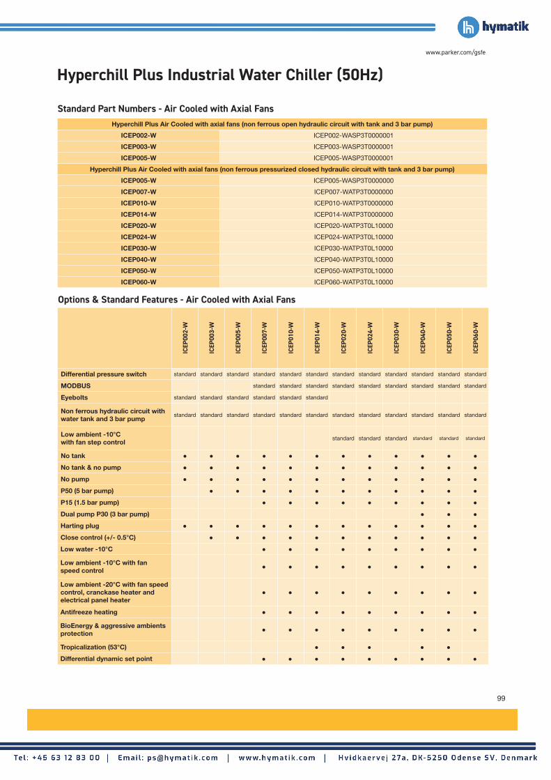
99
www.parker.com/gsfe
Options & Standard Features - Air Cooled with Axial Fans
ICEP
002-
W
ICEP
003-
W
ICEP
005-
W
ICEP
007-
W
ICEP
010-
W
ICEP
014-
W
ICEP
020-
W
ICEP
024-
W
ICEP
030-
W
ICEP
040-
W
ICEP
050-
W
ICEP
060-
W
Differential pressure switch standard standard standard standard standard standard standard standard standard standard standard standard
MODBUS standard standard standard standard standard standard standard standard standard
Eyebolts standard standard standard standard standard standard
Non ferrous hydraulic circuit with water tank and 3 bar pump
standard standard standard standard standard standard standard standard standard standard standard standard
Low ambient -10°C with fan step control
standard standard standard standard standard standard
No tank ● ● ● ● ● ● ● ● ● ● ● ●
No tank & no pump ● ● ● ● ● ● ● ● ● ● ● ●
No pump ● ● ● ● ● ● ● ● ● ● ● ●
P50 (5 bar pump) ● ● ● ● ● ● ● ● ● ● ●
P15 (1.5 bar pump) ● ● ● ● ● ● ● ● ●
Dual pump P30 (3 bar pump) ● ● ●
Harting plug ● ● ● ● ● ● ● ● ● ● ● ●
Close control (+/- 0.5°C) ● ● ● ● ● ● ● ● ● ● ●
Low water -10°C ● ● ● ● ● ● ● ● ●
Low ambient -10°C with fan speed control ● ● ● ● ● ● ● ● ●
Low ambient -20°C with fan speed control, cranckase heater and electrical panel heater
● ● ● ● ● ● ● ● ●
Antifreeze heating ● ● ● ● ● ● ● ● ●
BioEnergy & aggressive ambients protection ● ● ● ● ● ● ● ● ●
Tropicalization (53°C) ● ● ● ● ●
Differential dynamic set point ● ● ● ● ● ● ● ● ●
Standard Part Numbers - Air Cooled with Axial FansHyperchill Plus Air Cooled with axial fans (non ferrous open hydraulic circuit with tank and 3 bar pump)
ICEP002-W ICEP002-WASP3T0000001
ICEP003-W ICEP003-WASP3T0000001
ICEP005-W ICEP005-WASP3T0000001
Hyperchill Plus Air Cooled with axial fans (non ferrous pressurized closed hydraulic circuit with tank and 3 bar pump)
ICEP005-W ICEP005-WASP3T0000000
ICEP007-W ICEP007-WATP3T0000000
ICEP010-W ICEP010-WATP3T0000000
ICEP014-W ICEP014-WATP3T0000000
ICEP020-W ICEP020-WATP3T0L10000
ICEP024-W ICEP024-WATP3T0L10000
ICEP030-W ICEP030-WATP3T0L10000
ICEP040-W ICEP040-WATP3T0L10000
ICEP050-W ICEP050-WATP3T0L10000
ICEP060-W ICEP060-WATP3T0L10000
Hyperchill Plus Industrial Water Chiller (50Hz)

100
Thermal and Power Management
Hyperchill Plus Industrial Water Chiller (50Hz)
Options & Standard Features - Air Cooled with High Head Pressure Fan For Air Channeling
Options & Standard Features - Water Cooled
ICEP
040-
W
ICEP
050-
W
ICEP
060-
W
ICEP
014-
W
ICEP
020-
W
ICEP
024-
W
ICEP
030-
W
ICEP
040-
W
ICEP
050-
W
ICEP
060-
W
Differential pressure switch standard standard standard standard standard standard standard standard standard standard
MODBUS standard standard standard standard standard standard standard standard standard
Non ferrous hydraulic circuit with water tank and 3 bar pump
standard standard standard standard standard standard standard standard standard standard
Low ambient -10°C with fan step control
standard standard standard
No tank ● ● ● ● ● ● ● ● ● ●
No tank & no pump ● ● ● ● ● ● ● ● ● ●
No pump ● ● ● ● ● ● ● ● ● ●
P50 (5 bar pump) ● ● ● ● ● ● ● ● ● ●
P15 (1.5 bar pump) ● ● ● ● ● ● ● ● ●
Dual pump P30 (3 bar pump) ● ● ● ● ● ● ●
Harting plug ● ● ● ● ● ● ● ● ● ●
Close control (+/- 0.5°C) ● ● ● ● ● ● ● ● ● ●
Low water -10°C ● ● ● ● ● ● ● ● ● ●
Antifreeze heating ● ● ● ● ● ● ● ● ● ●
Differential dynamic set point ● ● ●
Standard Part Numbers - Air Cooled with High Head Pressure Fan For Air Channeling
Standard Part Numbers - Water Cooled
Hyperchill Plus Air Cooled with high head pressure fans for air channeling (non ferrous pressurized closed hydraulic
circuit with tank and 3 bar pump)
Hyperchill Plus Water Cooled (non ferrous pressurized closed hydraulic circuit
with tank and 3 bar pump)
ICEP014-W ICEP014-WWTP3T0000000
ICEP020-W ICEP020-WWTP3T0000000
ICEP024-W ICEP024-WWTP3T0000000
ICEP030-W ICEP030-WWTP3T0000000
ICEP040-W ICEP040-WCTP3T0L10000 ICEP040-W ICEP040-WWTP3T0000000
ICEP050-W ICEP050-WCTP3T0L10000 ICEP050-W ICEP050-WWTP3T0000000
ICEP060-W ICEP060-WWTP3T0000000 ICEP060-W ICEP060-WWTP3T0000000

101
www.parker.com/gsfe
Options & Standard Features - Air Cooled with High Head Pressure Fan For Air Channeling
Options & Standard Features - Water Cooled
ICEP
040-
W
ICEP
050-
W
ICEP
060-
W
ICEP
014-
W
ICEP
020-
W
ICEP
024-
W
ICEP
030-
W
ICEP
040-
W
ICEP
050-
W
ICEP
060-
W
Differential pressure switch standard standard standard standard standard standard standard standard standard standard
MODBUS standard standard standard standard standard standard standard standard standard
Non ferrous hydraulic circuit with water tank and 3 bar pump
standard standard standard standard standard standard standard standard standard standard
Low ambient -10°C with fan step control
standard standard standard
No tank ● ● ● ● ● ● ● ● ● ●
No tank & no pump ● ● ● ● ● ● ● ● ● ●
No pump ● ● ● ● ● ● ● ● ● ●
P50 (5 bar pump) ● ● ● ● ● ● ● ● ● ●
P15 (1.5 bar pump) ● ● ● ● ● ● ● ● ●
Dual pump P30 (3 bar pump) ● ● ● ● ● ● ●
Harting plug ● ● ● ● ● ● ● ● ● ●
Close control (+/- 0.5°C) ● ● ● ● ● ● ● ● ● ●
Low water -10°C ● ● ● ● ● ● ● ● ● ●
Antifreeze heating ● ● ● ● ● ● ● ● ● ●
Differential dynamic set point ● ● ●
Hyperchill Plus Industrial Water Chiller (60Hz UL*)
Versions
ICEP
002-
W
ICEP
003-
W
ICEP
005-
W
ICEP
007-
W
ICEP
010-
W
ICEP
014-
W
ICEP
020-
W
ICEP
024-
W
Open Circuit ● ● ● Available with ambient manual fill kit fitted
Closed Circuit ● ● ● ● ● ●
Water Cooled ● ● ●
Part Number Breakdown / Product Key
Pro
duc
t C
od
e
Mo
del
-
Flui
d t
o
be
Co
ole
d
Co
nden
ser
S
ecti
on
Po
wer
Sup
ply
Pum
ps
Wat
er T
ank
Co
ntro
l W
ater
Tem
p.
Low
Am
bie
nt
Low
Wat
er
Ant
ifree
ze
Fill
Kit
M
oun
ted
Op
tio
ns
ICEP 002 - W A F P1 T C FS 00 A 0 P
003 W G P3 0 0 L1 0 1 D
005 B P5 L2 2 C
007 00 00 3 1
010
014
020
024
W = Water
A = Air Axial
W = Water
B = Air Axial Bioenergy
F = 230V/1Ph/60Hz
G = 460V/3Ph/60Hz
T = With Tank
0 = Without Tank
P1 = Single Pump 1.5 bar
P2 = Single Pump 3 bar
P5 = Single Pump 5 bar
00 = No Pump
00 = No Low Water
A = With Antifreeze
0 = Without Antifreeze
Without Fill Kit
Ambient Manual Fill Kit
Ambient Automatic Fill Kit
Pressurised Fill Kit
P = Harting Plug For Signals
D = Differential Dynamic Set Point
C = Control Panel Cover
1 = Manual External Bypass
No Character = No Options Selected
C = Close Control +/- 0.5°C
0 = Without Close Control
FS = Fan Speed Control (Low Ambient -10°C)
L1 = Low Ambient -10°C (Fan Step Control)
L2 = Low Ambient -20°C
00 = No Low Ambient
ICEP = Hyperchill Plus
*ICEP002: UL Compliant / ICEP003-024: UL Listed

102
Thermal and Power Management
Standard Part Numbers - Air Cooled with Axial FansHyperchill Plus Air Cooled with axial fans (non ferrous open hydraulic circuit with tank and 3 bar pump)
ICEP002-W ICEP002-WAFP3T0000001
ICEP003-W ICEP003-WAFP3T0000001
ICEP005-W ICEP005-WAFP3T0000001
Hyperchill Plus Air Cooled with axial fans (non ferrous pressurized closed hydraulic circuit with tank and 3 bar pump)
ICEP005-W ICEP005-WAFP3T0000000
ICEP007-W ICEP007-WAGP3T0000000
ICEP010-W ICEP010-WAGP3T0000000
ICEP014-W ICEP014-WAGP3T0000000
ICEP020-W ICEP020-WAGP3T0L10000
ICEP024-W ICEP024-WAGP3T0L10000
Hyperchill Plus Industrial Water Chiller (60Hz UL*)
Options & Standard Features - Air Cooled with Axial Fans
ICEP
002-
W
ICEP
003-
W
ICEP
005-
W
ICEP
007-
W
ICEP
010-
W
ICEP
014-
W
ICEP
020-
W
ICEP
024-
W
Differential pressure switch standard standard standard standard standard standard standard standard
MODBUS standard standard standard standard standard
Eyebolts standard standard standard standard standard standard
Non ferrous hydraulic circuit with water tank and 3 bar pump
standard standard standard standard standard standard standard standard
Low ambient -10°C with fan step control
standard standard
No tank ● ● ● ● ● ● ● ●
No tank & no pump ● ● ● ● ● ● ● ●
No pump ● ● ● ● ● ● ● ●
P50 (5 bar pump) ● ● ● ● ● ● ●
P15 (1.5 bar pump) ● ● ● ● ●
Harting plug for signals ● ● ● ● ● ● ● ●
Close control (+/- 0.5°C) ● ● ● ● ● ● ●
Low water -10°C ● ● ● ● ●
Low ambient -10°C with fan speed control ● ● ● ● ●
Low ambient -20°C with fan speed control, cranckase heater and electrical panel heater
● ● ● ● ●
BioEnergy & aggressive ambients protection ● ● ● ● ●
Differential dynamic set point ● ● ● ● ●

103
www.parker.com/gsfe
Available Kits and Accessories
ICE
P00
2-W
ICE
P00
3-W
ICE
P00
5-W
ICE
P00
7 -
ICE
P01
4
ICE
P02
0 -
ICE
P03
0
ICE
P04
0 -
ICE
P06
0
Fill kit - ambient manual*** Non-ferrous ambient manual kits, for water filling in any installation.
398H785314 398H785314 398H785314
Fill kit - ambient automatic*** Non-ferrous ambient automatic kits,
for water filling in any installation.398H785316 398H785316 398H785316
Fill kit - pressurised automatic with expansion tank***
Non-ferrous pressurized, automatic kits, with expansion tank. For water filling
in any installation.
398H785312 398H785304 398H785304 398H785304
Remote control - base Base version for remote ON/OFF
and general alarm monitoring.398H785009 398H785009 398H785009 398H785010 398H785010 398H785010
Remote control - advanced Advanced version for
complete remote unit monitoring. 398H785307 398H785307 398H785307
Wheels For ease of transport.
398H785302 398H785301 398H785301 398H785301
Control panel cover*** 398H785303 398H785303 398H785303
Manual external bypass*** Non-ferrous, externally adjustable allowing the correct flow through
the system to be set.
398H785305 398H785305 398H785305 398H785306 398H785317
***From model ICEP007: ambient manual and automatic fill kit, pressurised automatic fill kit, control panel cover, manual external bypass can be supplied already installed or loose.
Hyperchill Plus - Kits and Accessories
Fill Kit - Ambient Fill Kit - Pressurised

104
Hyperchill Industrial Process Chiller
Thermal and Power Management
Hyperchill Industrial Process Chiller
Technical DataModel ICE 076 090 116 150 183 230 310 360
Cooling capacity1 kW 76.0 90.2 115.5 149.2 182.3 228 309 360
Compressor abs. power1 kW 15.4 20.3 24.9 30.8 40.1 51.4 65 82
SEPR3 5.39 4.97 5.08 5.35 5.04 4.80 5.51 4.57
Power supply V/ph/Hz 400/3/50 no neutral
Protection index 54
Refrigerant R407C
CompressorsType Hermetic scroll
Compressors/circuits 2/2 4/2
Max abs. power - 1 comp. kW 11.1 13.7 16.8 11.1 13.7 16.8 23.3 28.7
Axial FansQuantity n° 3 2 3 4
Max abs. power - 1 fan kW 0.78 0.78 0.78 2 2 2 2 2
Air flow m3/h 25500 25000 26400 47000 46000 66000 88000 88000
Centrifugal FansQuantity N° 3 3
N.A.Max abs. power - 1 fan kW 1.5 1.5 1.5 3 3 3
Air flow m3/h 25500 25000 26400 47000 46000 66000
Head pressure Pa 100 100 100 180 180 130
Water Cooled VersionCondenser water flow m3/h 11.1 11.5 16.6 19.2 31.0 33.0
N.A.Condensers connections in 1¼" 1¼" 1¼" 1 ¼" 1¼" 1½"
Pump P30Max abs.power kW 2.5 2.7 2.7 4.5 4.5 4.5 8.4 8.4
Water flow (nom/max)1 m3/h 13/31 15/27 20/27 25/50 30/50 39/50 53/90 62/90
Head pressure (nom/min)1 m H2O 23/13 28/16 25/16 34/20 32/20 26/20 26/19 23/19
Weights & DimensionsWidth mm 898 898 898 1287 1287 1287 1500 1500
Depth mm 2200 2200 2200 3000 3000 3260 4200 4200
Height mm 1984 1984 1984 2298 2298 2298 2240 2240
Connections in/out in 2" 2" 2" 2½" 2½" 2½" 4" 4"
Tank capacity l 500 500 500 1000 1000 1000 400 400
Weight (axial) kg 800 900 1000 1500 1800 2100 2900 3100
Weight (centrif.) kg 950 1050 1150 1700 2000 2300N.A.
Weight (water cooled) kg 800 900 1000 1500 1800 2100
Noise levelSound pressure (axial)2 dB(A) 58 58 58 62 62 64 65 65
1) At water in/out temperature 20/15°C, glycol 0%, either 25°C ambient temperature (air-cooled models) or 25°C condenser water inlet temperature with 35°C condensing temperature (water-cooled models).
2) Referred to axial fan version in free field conditions at a distance of 10 m from until, measured on condenser side, 1m from ground.
3) Value calculated in accordance with the European regulation (EU) 2016/2281 with regards to Ecodesign requirements for high temperature process chillers.
As the manufacturer of process chillers delivering water at a design temperature of 15°C, Parker Hannifin Manufacturing s.r.l.,Gas Separation and Filtration Division EMEA, declares that Parker chillers are exempt from Ecodesign EU regulation 2016/2281.

105
www.parker.com/gsfe
To obtain the required cooling capacity multiply the value at nominal conditions by the above correction factors (i.e. cooling capacity = Pxf1xf2xf3xf4, where P is the cooling capacity at conditions (1)). Hyperchill, in its standard configuration, can operate up to ambient temperatures of max 45°C and min. 5°C and water temperatures of max 30°C inlet and min. 0°C outlet. The above correction factors are approximative: for a precise selection always refer to the software selection programme.
WD
ICE076-116
Correction Factors
A) Ambient Temperature (Air Cooled Models)
°C 5 10 15 20 25 30 35 40 45
Correction Factor (f1) 1.05 1.05 1.05 1.05 1 0.95 0.89 0.83 0.77
B) Water Outlet Temperature °C 5 10 15 20 25
Correction Factor (f2) 0.72 0.86 1 1 1
C) Glycol % 0 10 20 30 40 50
Correction Factor (f3) 1 0.99 0.98 0.97 0.96 0.94
D) Condenser Water Inlet Temp. (Water Cooled Models)
°C 20 25 30 35 40
Correction Factor (f4) 1.05 1 0.95 0.9 0.85
H
W
D
H
ICE230
WD
H
ICE150 - 183 ICE310-360W
D
H

106
Thermal and Power Management
Hyperchill Industrial Process Chiller (50Hz)
Part Number Breakdown / Product Key
Pro
duc
t C
od
e
Mo
del
Co
nden
ser
S
ecti
on
Po
wer
Sup
ply
Pum
ps
Hyd
raul
ic
Cir
cuit
Co
ntro
l W
ater
Tem
p.
Low
Am
bie
nt
Low
Wat
er
Ant
ifree
ze
ICE 076 A 400350 1P15 FF C LA LW A
090 W 1P30 NF 0 L2 00 0
116 C 2P30 F0 00
150 B 1P50
183 0000
230
310
360
A = Air Axial
W = Water
C = Centrifugal
B = BioEnergy & Aggressive Ambients
400350 = 400V/3Ph/50Hz
FF = With Tank
NF = Non Ferrous
0 = Without Tank
1P15 = Single Pump 1.5 bar
1P30 = Single Pump 3 bar
2P30 = Dual Pump 3 bar
P5 = Single Pump 5 bar
000 = No Pump
LW = Low Water
00 = No Low Water
A = With Antifreeze
0 = Without Antifreeze
C = Close Control +/- 0.5°C
0 = Without Close Control
L1 = Low Ambient -10°C (Fan Step Control)
L2 = Low Ambient -20°C
00 = No Low Ambient
ICE = Hyperchill
Versions
ICE0
76
ICE0
90
ICE1
16
ICE1
50
ICE1
83
ICE2
30
ICE3
10
ICE3
60
Air Cooled with Axial Fans ● ● ● ● ● ● ● ●
Air Cooled with Centrifugal Fan For Air Channeling ● ● ● ● ● ●
Water Cooled ● ● ● ● ● ●

107
www.parker.com/gsfe
Options & Standard Features - Air Cooled with Axial Fans
ICE0
76
ICE0
90
ICE1
16
ICE1
50
ICE1
83
ICE2
30
ICE3
10
ICE3
60
Water tank standard standard standard standard standard standard ● ●
Without tank standard standard
P30 (3 bar pump) standard standard standard standard standard standard ● ●
No pump ● ● ● ● ● ● standard standard
P50 (5 bar pump) ● ● ● ● ● ● ● ●
P15 (1.5 bar pump) ● ● ● ● ● ● on request on request
Dual pump P30 (3 bar pump) ● ● ● ● ● ● ● ●
Close control (+/- 0.5°C) ● ● ● ● ● ●
Low water -10°C ● ● ● ● ● ● on request on request
Low ambient -10°C with fan step control ● ● ● ● ● ● standard standard
Low ambient -20°C with fan speed control, cranckase heater and electrical panel heater
● ● ● ● ● ● on request on request
Antifreeze heating ● ● ● ● ● ● on request on request
BioEnergy & aggressive ambients protection ● ● ● ● ● ● ● ●
Non ferrous hydraulic circuit ● ● ● ● ● ●
MODBUS on request on request on request on request on request on request on request on request
Standard Part Numbers - Air Cooled with Axial FansHyperchill Air Cooled with axial fans
ICE076 ICE076A4003501P30FF000000
ICE090 ICE090A4003501P30FF000000
ICE116 ICE116A4003501P30FF000000
ICE150 ICE150A4003501P30FF000000
ICE183 ICE183A4003501P30FF000000
ICE230 ICE230A4003501P30FF000000
ICE310 ICE310A4003501P30F00LA000
ICE360 ICE360A4003501P30F00LA000
Hyperchill Industrial Process Chiller (50Hz)
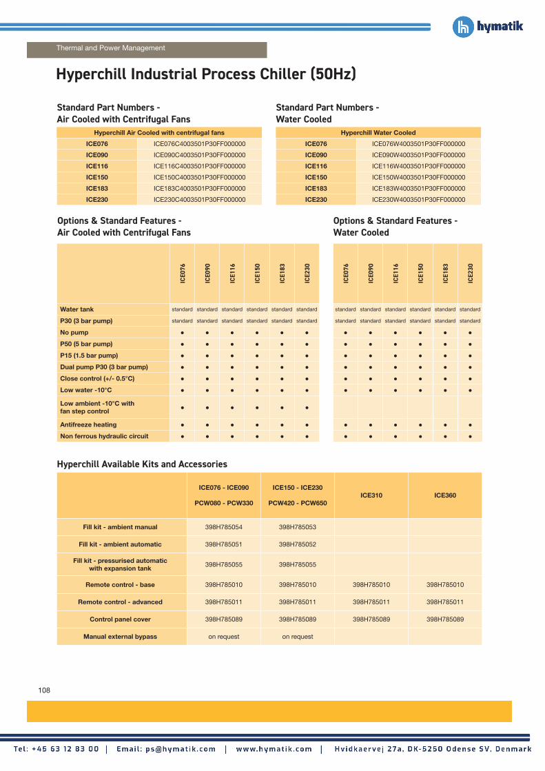
108
Thermal and Power Management
Options & Standard Features - Air Cooled with Centrifugal Fans
Options & Standard Features - Water Cooled
ICE0
76
ICE0
90
ICE1
16
ICE1
50
ICE1
83
ICE2
30
ICE0
76
ICE0
90
ICE1
16
ICE1
50
ICE1
83
ICE2
30
Water tank standard standard standard standard standard standard standard standard standard standard standard standard
P30 (3 bar pump) standard standard standard standard standard standard standard standard standard standard standard standard
No pump ● ● ● ● ● ● ● ● ● ● ● ●
P50 (5 bar pump) ● ● ● ● ● ● ● ● ● ● ● ●
P15 (1.5 bar pump) ● ● ● ● ● ● ● ● ● ● ● ●
Dual pump P30 (3 bar pump) ● ● ● ● ● ● ● ● ● ● ● ●
Close control (+/- 0.5°C) ● ● ● ● ● ● ● ● ● ● ● ●
Low water -10°C ● ● ● ● ● ● ● ● ● ● ● ●
Low ambient -10°C with fan step control ● ● ● ● ● ●
Antifreeze heating ● ● ● ● ● ● ● ● ● ● ● ●
Non ferrous hydraulic circuit ● ● ● ● ● ● ● ● ● ● ● ●
Standard Part Numbers - Air Cooled with Centrifugal Fans
Standard Part Numbers - Water Cooled
Hyperchill Air Cooled with centrifugal fans Hyperchill Water Cooled
ICE076 ICE076C4003501P30FF000000 ICE076 ICE076W4003501P30FF000000
ICE090 ICE090C4003501P30FF000000 ICE090 ICE090W4003501P30FF000000
ICE116 ICE116C4003501P30FF000000 ICE116 ICE116W4003501P30FF000000
ICE150 ICE150C4003501P30FF000000 ICE150 ICE150W4003501P30FF000000
ICE183 ICE183C4003501P30FF000000 ICE183 ICE183W4003501P30FF000000
ICE230 ICE230C4003501P30FF000000 ICE230 ICE230W4003501P30FF000000
Hyperchill Industrial Process Chiller (50Hz)
Hyperchill Available Kits and Accessories
ICE076 - ICE090
PCW080 - PCW330
ICE150 - ICE230
PCW420 - PCW650ICE310 ICE360
Fill kit - ambient manual 398H785054 398H785053
Fill kit - ambient automatic 398H785051 398H785052
Fill kit - pressurised automatic with expansion tank 398H785055 398H785055
Remote control - base 398H785010 398H785010 398H785010 398H785010
Remote control - advanced 398H785011 398H785011 398H785011 398H785011
Control panel cover 398H785089 398H785089 398H785089 398H785089
Manual external bypass on request on request

109
www.parker.com/gsfe
Hyperchill Industrial Water Chiller (60Hz UL)
Part Number Breakdown / Product Key
Pro
duc
t C
od
e
Mo
del
Co
nden
ser
S
ecti
on
Po
wer
Sup
ply
Pum
ps
Hyd
raul
ic
Cir
cuit
Co
ntro
l W
ater
Tem
p.
Low
Am
bie
nt
Low
Wat
er
Op
tio
ns
PCW 080 A 460360 1P30 FF C LA LW 0
110 B 1P50 NF 0 L2 00 M
130 0000 00
160
210
260
330
420
510
650
A = Air Axial
B = BioEnergy & Aggressive Ambients
460360 = 460V/3Ph/60Hz
FF = With Tank
NF = Non Ferrous
1P30 = Single Pump 3 bar
P5 = Single Pump 5 bar
000 = No Pump
LW = Low Water
00 = No Low Water
0 = No options
M = Modbus
C = Close Control +/- 0.5°C
Standard Control
LA = Low Ambient -10°C (Fan Step Control)
L2 = Low Ambient -20°C
00 = No Low Ambient
PCW = Hyperchill 60Hz
Options & Standard Features - Air Cooled with Axial Fans
PCW
080
PCW
110
PCW
130
PCW
160
PCW
210
PCW
260
PCW
330
PCW
420
PCW
510
PCW
650
Water tank standard standard standard standard standard standard standard standard standard standardP30 (3 bar pump) standard standard standard standard standard standard standard standard standard standardNo pump ● ● ● ● ● ● ● ● ● ●P50 (5 bar pump) ● ● ● ● ● ● ● ● ● ●P15 (1.5 bar pump) ● ● ● ● ● ● ● ● ● ●Close control (+/- 0.5°C) ● ● ● ● ● ● ● ● ● ●Low water -10°C ● ● ● ● ● ● ● ● ● ●
Low ambient -10°C with fan step control ● ● ● ● ● ● ● ● ● ●
Low ambient -20°C with fan speed control, cranckase heater and electrical panel heater
● ● ● ● ● ● ● ● ● ●
BioEnergy & aggressive ambients protection ● ● ● ● ● ● ● ● ● ●
Non ferrous hydraulic circuit ● ● ● ● ● ● ● ● ● ●MODBUS ● ● ● ● ● ● ● ● ● ●
Standard Part Numbers - Air Cooled with Axial FansHyperchill Air Cooled with axial fans
PCW080 PCW080A4603601P30FF000000
PCW110 PCW110A4603601P30FF000000
PCW130 PCW130A4603601P30FF000000
PCW160 PCW160A4603601P30FF000000
PCW210 PCW210A4603601P30FF000000
PCW260 PCW260A4603601P30FF000000
PCW330 PCW330A4603601P30FF000000
PCW420 PCW420A4603601P30FF000000
PCW510 PCW510A4603601P30FF000000
PCW650 PCW650A4603601P30FF000000

110
Hyperchill Laser Industrial Process Chiller
Thermal and Power Management
Technical DataModel HLS 076 090 116
Cooling capacity1 kW 76.0 90.2 115.5
Compressor abs. power1 kW 15.4 20.3 24.9
Cooling capacity2 kW 67.1 79.9 103.3
Compressor abs. power2 kW 18.7 24.2 29.9
Power supply V/ph/Hz 400/3/50 no neutral
Protection index 54
Refrigerant R407C
CompressorsType Hermetic scroll
Compressors/circuits 2/2
Max abs. power1 comp. kW 11.1 13.7 16.8
Axial fansQuantity n° 3
Max abs. power1 fan kW 0.78 0.78 0.78
Air flow m3/h 25500 25000 26400
1) At water inlet/outlet temperature = 20/15°C, glycol 0 %, ambient temperature 25°C.
2) At water inlet/outlet temperature = 25/20°C, glycol 0 %, ambient temperature 35°C.
3) Referred to free field conditions at a distance of 10m from unit, measured on condenser side, 1m from ground.
As the manufacturer of process chillers delivering water at a design temperature of 15°C, Parker Hannifin Manufacturing s.r.l.,Gas Separation and Filtration Division EMEA, declares that Parker chillers are exempt from Ecodesign EU regulation 2016/2281.
Pump P30Max abs.power kW 2.5 2.7 2.7
Water flow (nom/max)1 m3/h 13/31 15/27 20/27
Head pressure (nom/min)1 m H2O 23/13 28/16 25/16
Pump P50Max abs.power kW 4.5 4.5 4.5
Water flow (nom/max)1 m3/h 13.1/27 15.5/27 19.8/27
Head pressure (nom/min)1 m H2O 30/18 28/18 25/18
Weights & DimensionsWidth mm 898 898 898
Depth mm 2200 2200 2200
Height mm 1984 1984 1984
Connections in/out in 2" 2" 2"
Tank capacity l 300 300 300
Weight (axial) kg 750 870 960
Noise levelSound pressure (axial)3 dB(A) 58 58 58
Correction Factors
A) Ambient Temperature °C 5 10 15 20 25 30 35 40 45
Correction Factor (f1) 1.05 1.05 1.05 1.05 1 0.95 0.89 0.83 0.77
B) Water Outlet Temperature °C 5 10 15 20 25
Correction Factor (f2) 0.72 0.88 1 1 1
C) Glycol (by weight) % 0 10 20 30
Correction Factor (f3) 1 0.99 0.98 0.97
To obtain the required cooling capacity multiply the value at nominal conditions by the above correction factors (i.e. cooling capacity = Pxf1xf2xf3, where P is the cooling capacity at conditions (1). Hyperchill Laser, in its standard configuration, can operate up to ambient temperatures of max 48 °C for ICEP models, 45°C for HLS models and min 5 °C and water temperatures of max 30 °C inlet and min. 0°C outlet. The above correction factors are approximative: for a precise selection always refer to the software selection program

111
www.parker.com/gsfe
Part Number Breakdown / Product Key
Pro
duc
t C
od
e
Mo
del
Co
nden
ser
S
ecti
on
Po
wer
Sup
ply
Pum
ps
Hyd
raul
ic
Cir
cuit
Co
ntro
l W
ater
Tem
p.
Low
Am
bie
nt
Low
Wat
er
Ant
ifree
ze
HLS 076 A 400350 1P30 SS C LA 00 A
090 1P50 0
116 0000
A = Air Cooled
400350 = 400V/3Ph/50Hz
SS = Stainless Steel With Tank
1P30 = Single Pump 3 bar
P5 = Single Pump 5 bar
000 = No Pump
00 = No Low Water
A = Antifreeze
0 = No Antifreeze
C = Close Control +/- 0.5°C
LA = Low Ambient -10°C (Fan Step Control)
HLS = Hyperchill Laser
Options & Standard Features - Air Cooled with Axial Fans
HLS
076
HLS
090
HLS
116
Close control (+/- 0.5°C) standard standard standard
P30 (3 bar pump) standard standard standard
Low ambient -10°C standard standard standard
Stainless steel with tank standard standard standard
Antifreeze heating ● ● ●
No pump ● ● ●
P50 (5 bar pump) ● ● ●
Hyperchill Laser Available Kits and Accessories
HLS
076
HLS
090
HLS
116
Fill kit ambient manual standard standard standard
Remote control base 398H785010 398H785010 398H785010
Closed circuit 398H785011 398H785011 398H785011
Control panel cover 398H785089 398H785089 398H785089
Hydraulic bypass on request on request on request
Automatic check valves on request on request on request
Standard Part Numbers - Air Cooled with Axial FansHyperchill Laser Air Cooled with axial fans, non ferrous hydraulic circuit,
close control, low ambient temperature -10°C, manual fill kit.
HLS076 HLS076A4003501P30SSCLA000
HLS090 HLS090A4003501P30SSCLA000
HLS116 HLS116A4003501P30SSCLA000
W
D
HLS076-116
H

112
Industrial Nitrogen Gas Applications
Sizing and Selection - Thermal and Power Management Industrial Nitrogen Gas Generation
There are thousands of applications for industrial gases. Nitrogen is generally used for three main functions:
• It prevents microbial growth or acts as a filler gas in food applications
• It prevents slow oxidization of products such as chemicals and metals during processing or heating
• It prevents rapid oxidization of products that are flammable or explosive
PharmaceuticalWhether in primary or secondary pharmaceutical product manufacture or as a centralised QA laboratory supply; within research establishments or universities and colleges, Parker can offer a solution to suit the critical demands of this industry sector.
For blanketing of pharmaceutical product ingredients and pressure transfer within reactor vessels, to micronising powders to prevent oxidisation or explosion, Parker nitrogen generators can cut costs, reduce risk and improve productivity.
Centralised laboratory systems remove the need to have high pressure cylinders within the working environment and the possibility of running out of gas during a QA analysis procedure. Parker nitrogen gas generators are typically used for analytical equipment such as LC/MS, GC, reaction blanketing within fume cupboards, solvent evaporation, ICP, ELSD, NMR and circular dichroism.
Food and BeverageMost food products start to deteriorate from the moment they are harvested or prepared for packaging, being under attack from a multitude of spoilage mechanisms. By flushing, storing and/or packing with nitrogen, oxygen that many of these micro-organisms need in order to survive and multiply, is removed and the spoilage process is significantly reduced.
Prepared salads and vegetables, fresh chilled ready meals, meat, poultry, fish, dairy produce (including cheese), breads, coffee as well as snack foods such as potato chips and nuts can all benefit from ‘modified atmosphere packaging’ (or MAP as it is often referred to). By using nitrogen gas from a Parker generator, the product shelf life is increased and the appearance and quite often taste, is also improved.
Nitrogen is also used for ‘controlled atmosphere storage’ of fresh fruits and vegetables, sparging and blanketing food oils as well as bulk powders, cereals and liquid ingredients.
Alcoholic and non-alcoholic drinks and ingredients can suffer similar spoilage mechanisms to food, however one of the most significant threats to product quality is oxidisation which adversely affects product taste. Beer and wine can absorb unwanted dissolved oxygen throughout the production process. Oxygen can also reduce the effectiveness of natural or added vitamin C which maybe used in fruit juices.
Nitrogen gas generators provide an ideal cost effective solution for all of the processes involved in beverage production.
LasersLaser CuttingBy far the largest use of nitrogen gas within this industry sector is for laser cutting. Nitrogen gas is used as an ‘assist gas’ to prevent oxidisation or discolouration and to blow away the molten material from the cut edge.
It is also used in certain types of laser cutting machine as a ‘purge gas’ to ensure the laser beam guide path from the resonator (where
the beam is generated), to the cutting head, is free of contamination that could otherwise affect the power or alter the shape of the beam.
Laser SinteringLaser sintering or rapid prototyping uses a laser to form a solid 3D structure within a plastic powder material. Complex shapes and patterns can be constructed and modelled with ease. Nitrogen is used to blanket and prevent oxidisation of the powder material while it melts and solidifies to shape under the heat generated by the laser beam.
Laser AblationNitrogen is used to expel fumes and blanket delicate electronic circuits where a laser beam is used to erode pathways on micro printed circuit boards.
Laser Eye SurgeryNitrogen is used as a beam purge and pneumatics gas on Eximer laser machines which are used in the corrective treatment of eyesight defects.
Heat TreatmentNitrogen gas is commonly used to exclude oxygen from heat treatment furnaces and ovens. Parker can supply nitrogen gas generation systems to replace expensive bulk vessel liquid supplies for many heat treatment processes.
Typical applications include:• Belt furnaces
• Batch furnaces
• Vacuum ovens
• Brazing
• Carburising
• Tempering
• Annealing
• Gas quenching
• Neutral hardening
• Normalising
• Sintering
Fire Prevention and Archive ProtectionFrom the preservation of treasures for the generations after us, to preventing essential data destruction due to fire, Parker nitrogen generators provide a unique solution.
Oxygen depleted air can be pumped into buildings that house treasures and archives or computer stored data to help prevent total loss caused by fire. Museum pieces, paintings, artefacts, furniture and valuable fabrics can all be protected.
In general, only a modest reduction in normal ambient oxygen levels is enough to prevent fire. At 16% oxygen content, archives are protected whilst intermittent human exposure to these levels will have no adverse effects.

113
www.parker.com/gsfe
What Nitrogen Quality Do I Need?Traditional gas companies generally provide gas that is of high purity regardless of whether the application or process needs it. This is as a result of the ASU manufacturing process. Typically cylinder and liquid nitrogen has a maximum remaining oxygen content of between 5ppm to 20ppm v/v.
The majority of applications do not need such high purity gas and the benefit of using a higher oxygen content Parker generated gas is that less energy is used to produce it, so the unit gas cost will be more competitive.
For example using nitrogen with a maximum remaining oxygen content of 5% uses 5 times less energy to generate than with a maximum remaining oxygen content of 10ppm.
Providing customers with ultra-high purity nitrogen in all instances is an unnecessary waste of money and energy.
What do we mean by ‘purity’?By purity Parker means the maximum remaining oxygen content in the output nitrogen gas. Parker nitrogen technology when combined with Parker compressed air pre-treatment, guarantees the nitrogen gas to be commercially sterile, oil-free, dry and particulate free. (Within the specifications defined in the product information data contained in this catalogue.)
The maximum remaining oxygen content required will vary with every application. Maximum cost and energy savings = maximum oxygen level permissible
High Purity 10 ppm to 1000ppm (99.999% to 99.9%)
Laser cutting 50ppm to 500ppm
Heat treatment 10ppm to 1000ppm
Electronics soldering 50ppm to 500ppm
Pharmaceutical 10ppm to 5000ppm
Low Purity 1% to 5% (99% to 95%)
Fire prevention 5%
Explosion prevention 2% to 5%
Pressure testing 5%
Gas seal blanketing 5%
Pigging 5%
Chemical blanketing 1% to 5%
Autoclaves 5%
Laser sintering 2%
Dry boxes 2%
Mid Purity 0.1% to 1% (99.9% to 99%)
Food MAP 0.1% to 1%
Food processing 0.1% to 1%
Beer dispense 0.5%
Wine blanketing 0.5%
Oil sparging 0.5%
Brazing 0.5%
Injection molding 0.5% to 1%
Wire annealing 0.5%
Aluminium sparging 0.5%
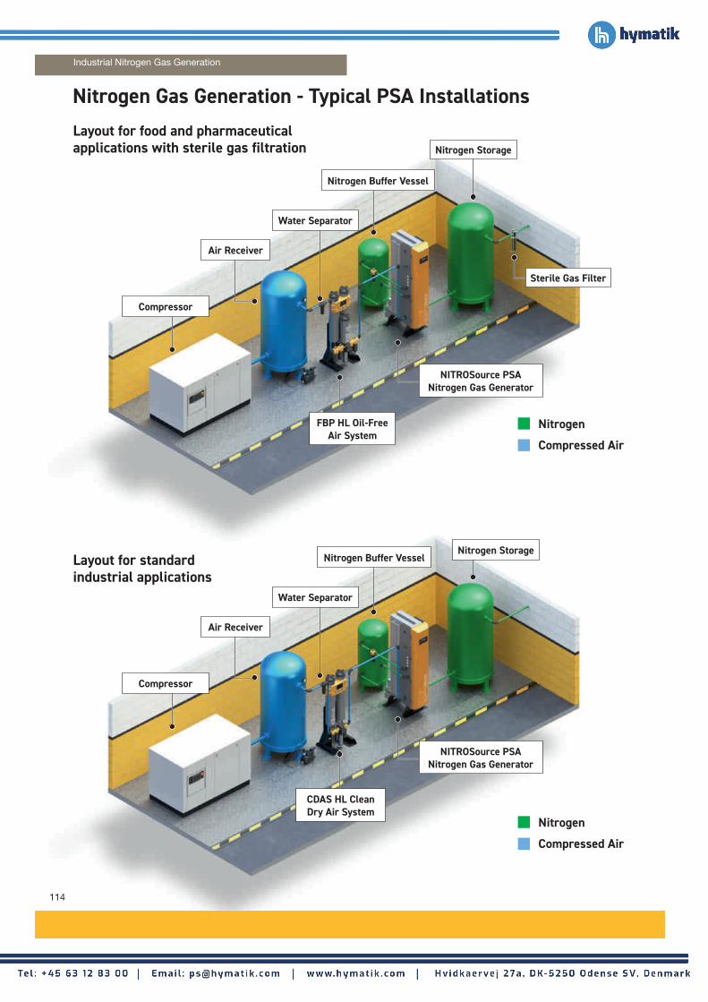
114
Layout for food and pharmaceutical applications with sterile gas filtration
Nitrogen Gas Generation - Typical PSA Installations
Industrial Nitrogen Gas Generation
Compressor
Layout for standard industrial applications
Air Receiver
Water Separator
Nitrogen Buffer Vessel
Sterile Gas Filter
FBP HL Oil-Free Air System
NITROSource PSA Nitrogen Gas Generator
Nitrogen
Compressed Air
Nitrogen Storage
Compressor
Air Receiver
Water Separator
Nitrogen Buffer Vessel
NITROSource PSA Nitrogen Gas Generator
Nitrogen
Compressed Air
Nitrogen Storage
CDAS HL Clean Dry Air System

115
www.parker.com/gsfe
Nitrogen
Compressed Air
Nitrogen
Compressed Air
Layout for high pressure 350 barg applications
Compressor
Air Receiver
Water Separator
CDAS HL Clean Dry Air System
NITROSource PSA Nitrogen Gas Generator
Nitrogen
Compressed Air
Low Pressure Nitrogen Storage
Layout for intermediate pressure 40 barg applications
Nitrogen Buffer Vessel
High Pressure Booster
High Pressure Manifold Cylinder Pack
High Pressure Coalescing Filters
Compressor
Air Receiver
Water Separator
NITROSource PSA Nitrogen Gas Generator
Nitrogen
Compressed Air
Low Pressure Nitrogen Storage
Nitrogen Buffer Vessel
40 barg Booster
High Pressure Coalescing Filters
40 barg Nitrogen Storage
CDAS HL Clean Dry Air System
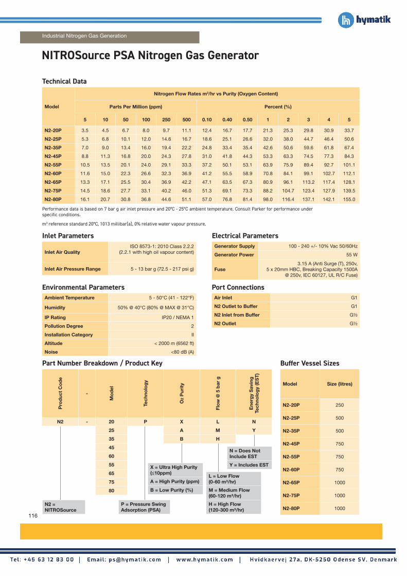
116
NITROSource PSA Nitrogen Gas Generator
Industrial Nitrogen Gas Generation
Technical Data
Model
Nitrogen Flow Rates m3/hr vs Purity (Oxygen Content)
Parts Per Million (ppm) Percent (%)
5 10 50 100 250 500 0.10 0.40 0.50 1 2 3 4 5
N2-20P 3.5 4.5 6.7 8.0 9.7 11.1 12.4 16.7 17.7 21.3 25.3 29.8 30.9 33.7
N2-25P 5.3 6.8 10.1 12.0 14.6 16.7 18.6 25.1 26.6 32.0 38.0 44.7 46.4 50.6
N2-35P 7.0 9.0 13.4 16.0 19.4 22.2 24.8 33.4 35.4 42.6 50.6 59.6 61.8 67.4
N2-45P 8.8 11.3 16.8 20.0 24.3 27.8 31.0 41.8 44.3 53.3 63.3 74.5 77.3 84.3
N2-55P 10.5 13.5 20.1 24.0 29.1 33.3 37.2 50.1 53.1 63.9 75.9 89.4 92.7 101.1
N2-60P 11.6 15.0 22.3 26.6 32.3 36.9 41.2 55.5 58.9 70.8 84.1 99.1 102.7 112.1
N2-65P 13.3 17.1 25.5 30.4 36.9 42.2 47.1 63.5 67.3 80.9 96.1 113.2 117.4 128.1
N2-75P 14.5 18.6 27.7 33.1 40.2 46.0 51.3 69.1 73.3 88.2 104.7 123.4 127.9 139.5
N2-80P 16.1 20.7 30.8 36.8 44.6 51.1 57.0 76.8 81.4 98.0 116.4 137.1 142.1 155.0
Inlet Parameters
Inlet Air QualityISO 8573-1: 2010 Class 2.2.2
(2.2.1 with high oil vapour content)
Inlet Air Pressure Range 5 - 13 bar g (72.5 - 217 psi g)
Environmental ParametersAmbient Temperature 5 - 50°C (41 - 122°F)
Humidity 50% @ 40°C (80% @ MAX @ 31°C)
IP Rating IP20 / NEMA 1
Pollution Degree 2
Installation Category II
Altitude < 2000 m (6562 ft)
Noise <80 dB (A)
Electrical ParametersGenerator Supply 100 - 240 +/- 10% Vac 50/60Hz
Generator Power 55 W
Fuse3.15 A (Anti Surge (T), 250v,
5 x 20mm HBC, Breaking Capacity 1500A @ 250v, IEC 60127, UL R/C Fuse)
Port ConnectionsAir Inlet G1
N2 Outlet to Buffer G1
N2 Inlet from Buffer G½
N2 Outlet G½
Performance data is based on 7 bar g air inlet pressure and 20°C - 25°C ambient temperature. Consult Parker for performance under specific conditions.
m3 reference standard 20°C, 1013 millibar(a), 0% relative water vapour pressure.
Part Number Breakdown / Product Key
Pro
duc
t C
od
e
-
Mo
del
Tech
nolo
gy
O2
Pur
ity
Flo
w @
5 b
ar g
Ene
rgy
Sav
ing
Te
chno
log
y (E
ST
)
N2 - 20 P X L N
25 A M Y
35 B H
45
60
55
65
75
80
N2 = NITROSource
X = Ultra High Purity (≤10ppm)
A = High Purity (ppm)
B = Low Purity (%)
P = Pressure Swing Adsorption (PSA)
Buffer Vessel Sizes
Model Size (litres)
N2-20P 250
N2-25P 500
N2-35P 500
N2-45P 750
N2-55P 750
N2-60P 750
N2-65P 1000
N2-75P 1000
N2-80P 1000
N = Does Not Include EST
Y = Includes EST
L = Low Flow (0-60 m³/hr)
M = Medium Flow (60-120 m³/hr)
H = High Flow (120-300 m³/hr)

www.parker.com/gsfe
W
H
D
Weights and Dimensions
Model
Unpacked Packed
Height (H) Width (W) Depth (D) Weight Height Width Depth Weight
mm ins mm ins mm ins kg lbs mm ins mm ins mm ins kg lbs
N2-20P
1894 74.6 550 21.7
881 34.7 299 658
729 28.7
2000 78.7
1090 42.9 398.4 876
N2-25P 1050 41.3 384 845 1260 49.6 495.4 1090
N2-35P 1219 48.0 469 1032 1430 56.3 580.4 1277
N2-45P 1388 54.6 553 1217 1600 63.0 686.4 1510
N2-55P 1557 61.3 638 1404
832 32.8
1770 69.7 782.4 1721
N2-60P 1726 68.0 722 1588 1935 76.2 897.4 1974
N2-65P 1895 74.6 807 1775 2100 82.7 997.4 2194
N2-75P 2064 81.3 892 1962 2275 89.6 1093.4 2405
N2-80P 2233 87.9 976 2147 2445 96.3 1186.4 2610
Preventative Maintenance KitsHigh Purity Generators (ppm) Low Purity Generators (%)
Model Without EST (Model Nos. N2XXPAXN)
With EST (Model Nos. N2XXPAXY)
Without EST (Model Nos. N2XXPBXN)
With EST (Model Nos. N2XXPBXY)
Kit Part Numbers
M12.NONEST.0001M24.PPM.0002M36.STD.0001M60.STD.0001
M12.EST.0001M24.PPM.0002M36.STD.0001M60.STD.0001
M12.NONEST.0001M24.PCT.0002M36.STD.0001M60.STD.0001
M12.EST.0001M24.PCT.0002M36.STD.0001M60.STD.0001
Kit Contents
Part Number Description / Service Interval Contents
M12.NONEST.0001 12 Month Non EST Service Kit (Every 12 Months)
Exhaust SilencerP025AO Dust Filter Element
M12.EST.0001 12 Month EST Service Kit(Every 12 Months)
Exhaust SilencerP025AO Dust Filter ElementIn-Line Filter
M24.PPM.0002 24 Month PPM Service Kit(Every 24 Months)
PPM Cell c/w Wiring
M24.PCT.0002 24 Month Percentage Service Kit(Every 24 Months)
% Cell c/w Wiring
M36.STD.0001 36 Month Standard Service Kit(Every 36 Months)
8 Bank Solenoid Valve
M60.STD.0001 60 Month Standard Service Kit(Every 24 Months)
40 x 25mm Stroke Cylinders (x6)Over Moulded Valve Discs and Guides (x6)50 x 100mm Stroke Cylinders (x2)Valve Discs (x2 Sets)Valve Bonnets (x2)Assorted O-RingsFixing Screws

118
NITROSource Compact PSA Nitrogen Gas Generator
Inlet Parameters
Inlet Air QualityISO 8573-1: 2010 Class 2.2.2
(2.2.1 with high oil vapour content)
Inlet Air Pressure Range 6 - 10 bar g (87 - 145 psi g)
Environmental ParametersAmbient Temperature 5 - 50°C (41 - 122°F)
Humidity 50% @ 40°C (80% @ MAX @ 31°C)
IP Rating IP20 / NEMA 1
Pollution Degree 2
Installation Category II
Altitude < 2000 m (6562 ft)
Noise <80 dB (A)
Electrical ParametersGenerator Supply 100 - 240 +/- 10% Vac 50/60Hz
Generator Power 55 W
Fuse3.15 A (Anti Surge (T), 250v,
5 x 20mm HBC, Breaking Capacity 1500A @ 250v, IEC 60127, UL R/C Fuse)
Port ConnectionsAir Inlet G1
N2 Outlet to Buffer G1
N2 Inlet from Buffer G½
N2 Outlet G½
Part Number Breakdown / Product Key
Pro
duc
t C
od
e
-
Mo
del
Tech
nolo
gy
Flo
w C
ont
rol
O2
Pur
ity
Max
imum
D
esig
n P
ress
ure
Out
let
Vers
ion
N2C - 2 N C A L N
4 B A
6
8
N2C = NITROSource Compact
C = Constant
N = Non Equalising
N = No Analyser
A = AnalyserA = High Purity (ppm)
B = Low Purity (%)
L = Low Pressure (6 - 10 bar g)
Industrial Nitrogen Gas Generation
Please contact Parker for NITROSource Compact performance data or visit parker.com/gsfe.

www.parker.com/gsfe
H
Weights and Dimensions
Model
Unpacked Packed
Height (H) Width (W) Depth (D) Weight Height Width Depth Weight
mm ins mm ins mm ins kg lbs mm ins mm ins mm ins kg lbs
N2C-2
1034 41 450 18
471 19 98 216
1490 59 612 24 950 38
174 383
N2C-4 640 26 145 320 221 487
N2C-6 809 33 196 432 272 597
N2C-8 977 38 249 549 303 668
Preventative Maintenance Kits
Part Number Description / Service Interval Contents
606280162 12 Month MIST–X Silencer Kit (Every 12 Months)
MIST–X 150 Silencer
P010AO 12 Month Filter Element Kit(Every 12 Months)
P001AO Dust Filter Element
M24.PPM.0002 24 Month PPM Service Kit(Every 24 Months)
PPM Cell c/w Wiring
M24.PCT.0002 24 Month Percentage Service Kit(Every 24 Months)
% Cell c/w Wiring
606510003 24 Month Valve Overhaul Kit - Generator With Analyser (Every 24 Months)
Air Inlet Valves (x2)Exhaust Valves (x2) Outlet Valves (x2)
606510005 24 Month Valve Overhaul Kit - Generator Without Analyser (Every 24 Months)
Air Inlet Valves (x2)Exhaust Valves (x2) Outlet Valve
WD

120
Industrial Nitrogen Gas Generation - Membrane Modules
NoteParker membrane systems produce both nitrogen and oxygen enriched air. Nitrogen enriched air can cause suffocation and oxygen enriched air causes increased fire hazards. The oxygen enriched air is available at ambient pressure and pressure build-up of enriched oxygen at the outlet must be prevented, otherwise a serious (reversible) decrease in performance will result. The nitrogen enriched air produced should be treated as pressurised air.
Performance dataPerformance data is based on 20°C feed-air temperature and 1013 mbar ambient pressure
Purity %
Typical Nitrogen1) flow rate in m3/hr2) (SCFM)
99.5 99.0 98.0 97.0 96.0 95.0
4 bar g(58 psi g)
0.20(0.12)
0.32(0.19)
0.50(0.29)
0.73(0.43)
0.84(0.49)
1.04(0.61)
5 bar g(72.5 psi g)
0.28(0.16)
0.46(0.27)
0.73(0.43)
0.92(0.54)
1.17(0.69)
1.54(0.91)
6 bar g(87 psi g)
0.44(0.21)
0.60(0.35)
0.92(0.54)
1.20(0.71)
1.53(0.9)
1.75(1.03)
7 bar g(101.5 psi g)
0.44(0.26)
0.71(0.42)
1.16(0.68)
1.49(0.88)
1.90(1.12)
2.10(1.24)
8 bar g(116 psi g)
0.54(0.32)
0.85(0.5)
1.31(0.77)
1.75(0.77)
2.17(1.28)
2.60(1.53)
9 bar g(130.5 psi g)
0.59(0.35)
0.97(0.57)
1.54(0.91)
2.08(1.22)
2.50(1.47)
3.00(1.77)
10 bar g(145 psi g)
0.67(0.39)
1.11(0.65)
1.78(1.05)
2.29(1.35)
2.80(1.65)
3.40(2)
11 bar g(159.5 psi g)
0.73(0.43)
1.25(0.74)
1.95(1.15)
2.57(1.51)
3.20(1.88)
3.90(2.3)
12 bar g(174 psi g)
0.79(0.46)
1.39(0.82)
2.17(1.28)
2.80(1.65)
3.40(2)
4.20(2.47)
13 bar g(188.5 psi g)
0.89(0.52)
1.49(0.88)
2.40(1.41)
3.10(1.82)
3.80(2.24)
4.80(2.83)
Purity %
Typical Feed-air consumption at nitrogen flow rate in m3/hr2) (SCFM)
99.5 99.0 98.0 97.0 96.0 95.0
4 bar g(58 psi g)
1.9(1.1)
1.8(1.1)
1.9(1.1)
2.3(1.4)
2.3(1.4)
2.5(1.5)
5 bar g(72.5 psi g)
2.2(1.3)
2.3(1.4)
2.6(1.5)
2.7(1.6)
3.0(1.8)
3.6(2.1)
6 bar g(87 psi g)
2.5(1.5)
2.8(1.6)
3.2(1.9)
3.4(2)
3.9(2.3)
4.0(2.4)
7 bar g(101.5 psi g)
3.0(1.8)
3.3(1.9)
3.9(2.3)
4.2(2.5)
4.8(2.8)
4.7(2.8)
8 bar g(116 psi g)
3.5(2.1)
3.8(2.2)
4.4(2.6)
4.9(2.9)
5.4(3.2)
5.8(3.4)
9 bar g(130.5 psi g)
3.7(2.2)
4.3(2.5)
5.1(3)
5.8(3.4)
6.3(3.7)
6.7(3.9)
10 bar g(145 psi g)
4.1(2.4)
4.8(2.8)
5.9(3.5)
6.3(3.7)
7.0(4.1)
7.5(4.4)
11 bar g(159.5 psi g)
4.4(2.6)
5.3(3.1)
6.3(3.7)
7.1(4.2)
7.9(4.6)
8.5(5)
12 bar g(174 psi g)
4.6(2.7)
5.9(3.5)
7.0(4.1)
7.7(4.5)
8.4(4.9)
9.3(5.5)
13 bar g(188.5 psi g)
5.5(3.2)
6.4(3.8)
7.9(4.6)
8.7(5.1)
9.5(5.6)
10.7(6.3)
Maximum pressure drop <0.1 bar.Values between brackets are indicative imperial values
Ambient temperature +2°C to +50°C (+36°F to 122°F)
Ambient pressure atmospheric
Air quality clean air without contaminants
Nitrogen flow rate at feed-air temperatures other than 20ºC
Use bulletin S3.1.240*
Feed-air consumption at feed-air temperatures other than 20ºC
Use bulletin S3.1.240*
Housing Steel
Tube Aluminum
Coating (housing) ESPC to RAL 7039 (Quartz Grey)
Coating (tube) none
3D model CAD STEP fileMaximum operating pressure 13.0 bar g (190 psi g)
Min. / Max. operating temperature +2°C to +50°C (+36°F to 122°F)
Maximum oil vapour content <0.01 mg/m3 (<0.01 ppm (w))
Particles filtered at 0.01 µm cut off
Relative humidity <100% (non condensing) Dimensions H x W x D758 x 80 x 63 mm
(29.84" x 3.15" x 2.48")
Weight 3.2 kg (7.05 lb)
Connection feed-air G3/8 female to ISO 228
Connection nitrogen enriched air G3/8 female to ISO 228
Connection oxygen enriched air at atmospheric pressure
G3/8 female to ISO 228
Dimensional drawing Refer to K3.1.344
1) The above data represents the typical performance of a single membrane module. Actual performance can vary depending on factors such as feed air pressure and temperature. Please contact your Parker go to person for actual performance information to meet your application’s requirements.2) m3/hr refers to conditions at 1013 mbar(a) and 20°C.For higher purities please contact Parker
SmartFluxx SA604
* Revision number may vary, make sure to use the most recent Revision
Ambient Conditions
Flow Rate Corrections
Material
Services on RequestFeed-air Conditions
Weight, Dimensions and Connections
H
W
D
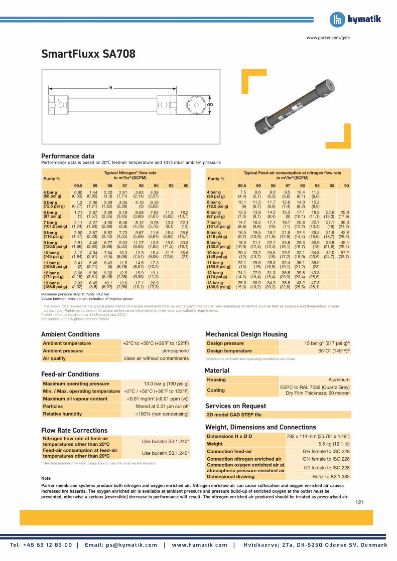
www.parker.com/gsfe
NoteParker membrane systems produce both nitrogen and oxygen enriched air. Nitrogen enriched air can cause suffocation and oxygen enriched air causes increased fire hazards. The oxygen enriched air is available at ambient pressure and pressure build-up of enriched oxygen at the outlet must be prevented, otherwise a serious (reversible) decrease in performance will result. The nitrogen enriched air produced should be treated as pressurised air.
Performance dataPerformance data is based on 20°C feed-air temperature and 1013 mbar ambient pressure
121
SmartFluxx SA708
1) The above data represents the typical performance of a single membrane module. Actual performance can vary depending on factors such as feed air pressure and temperature. Please contact your Parker go to person for actual performance information to meet your application’s requirements.2) m3/hr refers to conditions at 1013mbar(a) and 20°C.For purities >99.5% please contact Parker
Maximum pressure drop at Purity <0.2 barValues between brackets are indicative of imperial values
Ambient temperature +2°C to +50°C (+36°F to 122°F)
Ambient pressure atmospheric
Air quality clean air without contaminants
Nitrogen flow rate at feed-air temperatures other than 20ºC
Use bulletin S3.1.240*
Feed-air consumption at feed-air temperatures other than 20ºC
Use bulletin S3.1.240*
4 Membrane ambient and operating conditions are lower
Design pressure 15 bar g4) (217 psi g)4)
Design temperature 65ºC4) (149ºF)4)
Housing Aluminum
CoatingESPC to RAL 7039 (Quartz Grey)
Dry Film Thickness: 60 micron
3D model CAD STEP file
Maximum operating pressure 13.0 bar g (190 psi g)
Min. / Max. operating temperature +2°C / +50°C (+36°F to 122°F)
Maximum oil vapour content <0.01 mg/m3 (<0.01 ppm (w))
Particles filtered at 0.01 µm cut off
Relative humidity <100% (non condensing)
Dimensions H x Ø D 782 x 114 mm (30.79" x 4.49")
Weight 5.5 kg (12.1 lb)
Connection feed-air G¾ female to ISO 228
Connection nitrogen enriched air G¾ female to ISO 228Connection oxygen enriched air at atmospheric pressure enriched air
G1 female to ISO 228
Dimensional drawing Refer to K3.1.383
Purity %Typical Nitrogen1) flow rate
in m3/hr2) (SCFM)
99.5 99 98 97 96 95 93 90
4 bar g(58 psi g)
0.90 (0,53)
1.44 (0,85)
2.20 (1,3)
2.91 (1,71)
3.63 (2,14)
4.36 (2,57)
5 bar g(72.5 psi g)
1.3(0,77)
2.06 (1,21)
3.09 (1,82)
4.05 (2,38)
5.10 (3)
6.15 (3,62)
6 bar g(87 psi g)
1.71 (1)
2.67 (1,57)
3.99 (2,35)
5.18 (3,05)
6.56 (3,86)
7.94 (4,67)
11.3 (6,62)
18.2 (10,7)
7 bar g(101.5 psi g)
2.11 (1,24)
3.27 (1,93)
4.90 (2,89)
6.46 (3,8)
8.12 (4,78)
9.78 (5,76)
13.8 (8,1)
22.1 (13)
8 bar g(116 psi g)
2.50 (1,47)
3.87 (2,28)
5.82 (3,42)
7.73 (4,55)
9.67 (5,69)
11.6 (6,84)
16.4 (9,63)
26.6 (15,7)
9 bar g(130.5 psi g)
2.81 (1,66)
4.46 (2,62)
6.77 (3,98)
9.03 (5,32)
11.27 (6,63)
13.5 (7,95)
19.0 (11,2)
30.8 (18,1)
10 bar g(145 psi g)
3.12 (1,84)
4.94 (2,91)
7.64 (4,5)
10.3 (6,08)
12.9 (7,57)
15.4 (9,06)
21.7 (12,8)
35.6 (21)
11 bar g(159.5 psi g)
3.41 (2)
5.46 (3,21)
8.49 (5)
11.5 (6,78)
14.5 (8,51)
17.3 (10,2)
12 bar g(174 psi g)
3.68 (2,16)
5.96 (3,51)
9.32 (5,49)
12.5 (7,38)
15.9 (9,35)
19.1 (11,2)
13 bar g(188.5 psi g)
3.93 (2,32)
6.45 (3,8)
10.1 (5,92)
13.6 (7,98)
17.1 (10,1)
20.9 (12,3)
Purity %Typical Feed-air consumption at nitrogen flow rate
in m3/hr2) (SCFM)
99.5 99 98 97 96 95 93 90
4 bar g(58 psi g)
7.5 (4,4)
8.6 (5,1)
9.0 (5,3)
9.5 (5,6)
10.4 (6,1)
11.2 (6,6)
5 bar g(72.5 psi g)
10.1 (6)
11.5 (6,7)
11.7 (6,9)
12.6 (7,4)
14.0 (8,2)
15.2 (8,9)
6 bar g(87 psi g)
12.3 (7,2)
13.8 (8,1)
14.2 (8,4)
15.3 (9)
17.1 (10,1)
18.8 (11,1)
22.6 (13,3)
29.9 (17,6)
7 bar g(101.5 psi g)
14.7 (8,6)
16.2 (9,6)
17.1 (10)
18.7 (11)
20.8 (12,2)
22.7 (13,4)
27.1 (16)
36.0 (21,2)
8 bar g(116 psi g)
16.5 (9,7)
18.5 (10,9)
19.7 (11,6)
21.9 (12,9)
24.4 (14,4)
26.5 (15,6)
31.8 (18,7)
42.8 (25,2)
9 bar g(130.5 psi g)
18.5 (10,9)
21.1 (12,4)
22.7 (13,4)
25.6 (15,1)
28.3 (16,7)
30.6 (18)
36.8 (21,6)
49.4 (29,1)
10 bar g(145 psi g)
20.4 (12)
23.2 (13,7)
25.5 (15)
29.2 (17,2)
32.1 (18,9)
34.8 (20,5)
42.0 (24,7)
57.2 (33,7)
11 bar g(159.5 psi g)
22.1 (13)
25.5 (15)
28.3 (16,6)
32.4 (19,1)
36.1 (21,2)
39.0 (23)
12 bar g(174 psi g)
24.1 (14,2)
27.9 (16,4)
31.3 (18,4)
35.5 (20,9)
39.8 (23,4)
43.3 (25,5)
13 bar g(188.5 psi g)
25.9 (15,3)
30.9 (18,2)
34.3 (20,2)
38.8 (22,8)
43.2 (25,5)
47.8 (28,1)
Mechanical Design Housing
* Revision number may vary, make sure to use the most recent Revision
Ambient Conditions
Flow Rate Corrections
Feed-air Conditions Material
Services on Request
Weight, Dimensions and Connections
H
ØD

122
Industrial Nitrogen Gas Generation - Membrane Modules
NoteParker membrane systems produce both nitrogen and oxygen enriched air. Nitrogen enriched air can cause suffocation and oxygen enriched air causes increased fire hazards. The oxygen enriched air is available at ambient pressure and pressure build-up of enriched oxygen at the outlet must be prevented, otherwise a serious (reversible) decrease in performance will result. The nitrogen enriched air produced should be treated as pressurised air.
Performance dataPerformance data is based on 20°C feed-air temperature and 1013 mbar ambient pressure
SmartFluxx SA1508
Purity %
Typical Nitrogen1) flow rate in m3/hr2) (SCFM)
99.5 99.0 98.0 97.0 96.0 95.0
4 bar g(58 psi g)
2.8(1.6)
4.0(2.4)
5.7(3.4)
7.1(4.2)
9.5(5.6)
10.9(6.4)
5 bar g(72.5 psi g)
3.7(2.2)
5.3(3.1)
7.9(4.6)
10.2(6)
12.8(7.5)
15.2(8.9)
6 bar g(87 psi g)
4.7(2.8)
7.0(4.1)
10.2(6)
13.0(7.7)
15.7(9.2)
20.5(12.1)
7 bar g(101.5 psi g)
6.1(3.6)
8.5(5)
12.3(7.2)
16.5(9.7)
19.5(11.5)
24.3(14.3)
8 bar g(116 psi g)
6.9(4.1)
9.7(5.7)
14.3(8.4)
20.2(11.9)
23.3(13.7)
28.1(16.5)
9 bar g(130.5 psi g)
7.8(4.6)
11.1(6.5)
17.0(10)
22.2(13.1)
27.0(15.9)
32.2(19)
10 bar g(145 psi g)
8.6(5.1)
12.6(7.4)
18.5(10.9)
24.2(14.2)
30.2(17.8)
37.4(22)
11 bar g(159.5 psi g)
9.6(5.7)
14.2(8.4)
20.7(12.2)
27.3(16.1)
33.0(19.4)
41.0(24.1)
12 bar g(174 psi g)
10.5(6.2)
15.2(8.9)
22.9(13.5)
29.5(17.4)
36.6(21.5)
45.6(26.8)
13 bar g(188.5 psi g)
11.3(6.7)
16.3(9.6)
24.9(14.7)
32.0(18.8)
39.5(23.2)
48.8(28.7)
Purity %
Typical Feed-air consumption at nitrogen flow rate in m3/hr2) (SCFM)
99.5 99.0 98.0 97.0 96.0 95.0
4 bar g(58 psi g)
21(12)
21(12)
22(13)
22(13)
26(15)
27(16)
5 bar g(72.5 psi g)
24(14)
26(15)
29(17)
31(18)
34(20)
36(21)
6 bar g(87 psi g)
29(17)
33(19)
36(21)
38(22)
41(24)
48(28)
7 bar g(101.5 psi g)
36(21)
38(22)
41(24)
48(28)
50(29)
56(33)
8 bar g(116 psi g)
38(22)
42(25)
47(28)
56(33)
58(34)
63(37)
9 bar g(130.5 psi g)
44(26)
48(28)
55(32)
62(36)
67(39)
72(42)
10 bar g(145 psi g)
50(29)
56(33)
61(36)
68(40)
75(44)
84(49)
11 bar g(159.5 psi g)
51(30)
60(35)
66(39)
74(44)
80(47)
91(54)
12 bar g(174 psi g)
57(34)
65(38)
76(45)
83(49)
92(54)
103(61)
13 bar g(188.5 psi)
66(39)
72(42)
85(50)
92(54)
101(59)
113(67)
1) The above data represents the typical performance of a single membrane module. Actual performance can vary depending on factors such as feed air pressure and temperature. Please contact your Parker go to person for actual performance information to meet your application’s requirements.2) m3/hr refers to conditions at 1013 mbar(a) and 20°CFor purities >99.5% please contact Parker
* Revision number may vary, make sure to use the most recent revision
Maximum pressure drop at Purity <0.2 barValues between brackets are indicative of imperial values
Ambient temperature +2°C to +50°C (+36°F to 122°F)
Ambient pressure atmospheric
Air quality clean air without contaminants
Nitrogen flow rate at feed-air temperatures other than 20ºC
Use bulletin S3.1.240*
Feed-air consumption at feed-air temperatures other than 20ºC
Use bulletin S3.1.240*
4) Membrane ambient and operating conditions are lower
Design pressure 15 bar g4) (217 psi g)4)
Design temperature 65ºC4) (149ºF)4)
Housing Aluminum
CoatingESPC to RAL 7039 (Quartz Grey)
Dry Film Thickness: 60 micron
Material certificates EN10204-3.1 on housing material (for Stainless Steel only)3D model CAD STEP file
Maximum operating pressure 13.0 bar g (190 psi g)
Min. / Max. operating temperature +2°C / +50°C (+36°F to 122°F)
Maximum oil vapour content <0.01 mg/m3 (<0.01 ppm (w))
Particles filtered at 0.01 µm cut off
Relative humidity <100% (non condensing)Dimensions H x Ø D 1655 x 114 mm (65.12" x 4.49")
Weight 6.8 kg (15 lb)
Connection feed-air G¾ female to ISO 228
Connection nitrogen enriched air G¾ female to ISO 228
Connection oxygen enriched air at atmospheric pressure
G1 female to ISO 228
Dimensional drawing Refer to K3.1.330
Mechanical Design Housing
Ambient Conditions
Flow Rate Corrections
Feed-air Conditions Services on Request
Weight, Dimensions and Connections
Material
H
ØD

www.parker.com/gsfe
NoteParker membrane systems produce both nitrogen and oxygen enriched air. Nitrogen enriched air can cause suffocation and oxygen enriched air causes increased fire hazards. The oxygen enriched air is available at ambient pressure and pressure build-up of enriched oxygen at the outlet must be prevented, otherwise a serious (reversible) decrease in performance will result. The nitrogen enriched air produced should be treated as pressurised air.
Performance dataPerformance data is based on 20°C feed-air temperature and 1013 mbar ambient pressure
123
SmartFluxx SA1508SS
Purity %
Typical Nitrogen1) flow rate in m3/hr2) (SCFM)
99.5 99.0 98.0 97.0 96.0 95.0
4 bar g(58 psi g)
2.8(1.6)
4.0(2.4)
5.7(3.4)
7.1(4.2)
9.5(5.6)
10.9(6.4)
5 bar g(72.5 psi g)
3.7(2.2)
5.3(3.1)
7.9(4.6)
10.2(6)
12.8(7.5)
15.2(8.9)
6 bar g(87 psi g)
4.7(2.8)
7.0(4.1)
10.2(6)
13.0(7.7)
15.7(9.2)
20.5(12.1)
7 bar g(101.5 psi g)
6.1(3.6)
8.5(5)
12.3(7.2)
16.5(9.7)
19.5(11.5)
24.3(14.3)
8 bar g(116 psi g)
6.9(4.1)
9.7(5.7)
14.3(8.4)
20.2(11.9)
23.3(13.7)
28.1(16.5)
9 bar g(130.5 psi g)
7.8(4.6)
11.1(6.5)
17.0(10)
22.2(13.1)
27.0(15.9)
32.2(19)
10 bar g(145 psi g)
8.6(5.1)
12.6(7.4)
18.5(10.9)
24.2(14.2)
30.2(17.8)
37.4(22)
11 bar g(159.5 psi g)
9.6(5.7)
14.2(8.4)
20.7(12.2)
27.3(16.1)
33.0(19.4)
41.0(24.1)
12 bar g(174 psi g)
10.5(6.2)
15.2(8.9)
22.9(13.5)
29.5(17.4)
36.6(21.5)
45.6(26.8)
13 bar g(188.5 psi g)
11.3(6.7)
16.3(9.6)
24.9(14.7)
32.0(18.8)
39.5(23.2)
48.8(28.7)
Purity %
Typical Feed-air consumption at nitrogen flow rate in m3/hr2) (SCFM)
99.5 99.0 98.0 97.0 96.0 95.0
4 bar g(58 psi g)
21(12)
21(12)
22(13)
22(13)
26(15)
27(16)
5 bar g(72.5 psi g)
24(14)
26(15)
29(17)
31(18)
34(20)
36(21)
6 bar g(87 psi g)
29(17)
33(19)
36(21)
38(22)
41(24)
48(28)
7 bar g(101.5 psi g)
36(21(
38(22)
41(24)
48(28)
50(29)
56(33)
8 bar g(116 psi g)
38(22)
42(25)
47(28
56(33)
58(34)
63(37)
9 bar g(130.5 psi g)
44(26)
48(28)
55(32)
62(36)
67(39)
72(42)
10 bar g(145 psi g)
50(29)
56(33)
61(36)
68(40)
75(75)
84(44)
11 bar g(159.5 psi g)
51(30)
60(35)
66(39)
74(44)
80(47)
91(54)
12 bar g(174 psi g)
57(34)
65(38)
76(45)
83(49)
92(54)
103(61)
13 bar g(188.5 psi g)
66(39)
72(42)
85(50)
92(54)
101(59)
113(67)
Maximum pressure drop at Purity <0.2 barValues between brackets are indicative of imperial values
Ambient temperature +2°C to +50°C (+36°F to 122°F)
Ambient pressure atmospheric
Air quality clean air without contaminants
Nitrogen flow rate at feed-air temperatures other than 20ºC
Use bulletin S3.1.240*
Feed-air consumption at feed-air temperatures other than 20ºC
Use bulletin S3.1.240*
4) Membrane operating limits are lower
Design pressure 15 bar g4) (217 psi g)4)
Design temperature 65ºC4) (149ºF)4)
Housing Stainless Steel
Coating None
Material certificates EN10204-3.1 on housing material (for Stainless Steel only)
3D model CAD STEP file
Maximum operating pressure 13.0 bar g (190 psi g)
Min. / Max. operating temperature +2°C to +50°C (+36°F to 122°F)
Maximum oil vapour content <0.01 mg/m3 (<0.01 ppm (w))
Particles filtered at 0.01 µm cut offRelative humidity <100% (non condensing)
Dimensions H x Ø D 1654 x 114 mm (65.12" x 4.49")
Weight 18 kg (40 lb)
Connection feed-air G¾ female to ISO 228
Connection nitrogen enriched air G¾ female to ISO 228
Connection oxygen enriched air at atmospheric pressure
G1 female to ISO 228
Dimensional drawing Refer to K3.1.330
1) The above data represents the typical performance of a single membrane module. Actual performance can vary depending on factors such as feed air pressure and temperature. Please contact your Parker go to person for actual performance information to meet your application’s requirements.2) m3/hr refers to conditions at 1013 mbar(a) and 20°CFor purities >99.5% please contact Parker
Mechanical Design Housing
Ambient Conditions
Flow Rate Corrections
Feed-air Conditions Services on Request
Weight, Dimensions and Connections
Material
* Revision number may vary, make sure to use the most recent revision
H
ØD

124
Industrial Nitrogen Gas Generation - Membrane Modules
NoteParker membrane systems produce both nitrogen and oxygen enriched air. Nitrogen enriched air can cause suffocation and oxygen enriched air causes increased fire hazards. The oxygen enriched air is available at ambient pressure and pressure build-up of enriched oxygen at the outlet must be prevented, otherwise a serious (reversible) decrease in performance will result. The nitrogen enriched air produced should be treated as pressurised air.
Performance dataPerformance data is based on 20°C feed-air temperature and 1013 mbar ambient pressure
SmartFluxx SA15020
Purity %Typical Nitrogen1) flow rate
in m3/hr2) (SCFM)
99.5 99.0 98.0 97.0 96.0 95.0
4 bar g(58 psi g)
17 (10)
25(15)
36(21)
47(28)
57(34)
70(41)
5 bar g(72.5 psi g)
23(14)
33(19)
49(29)
66(39)
82(48)
93(55)
6 bar g(87 psi g)
29 (17)
43(25)
63(37)
83 (49)
102(60)
120(71)
7 bar g(101.5 psi g)
37 (22)
53(31)
78(46)
100(59)
125(74)
154(91)
8 bar g(116 psi g)
44 (26)
62(36)
90(53)
117(69)
144(85)
178(105)
9 bar g(130.5 psi g)
49 (29)
72(42)
103(61)
133(78)
165(97)
216(127)
Purity %Typical Feed-air consumption at
nitrogen flow rate in m3/hr2) (SCFM)
99.5 99.0 98.0 97.0 96.0 95.0
4 bar g(58 psi g)
127(75)
126(74)
135(79)
145(85)
155(91)
169(99)
5 bar g(72.5 psi g)
144(85)
155(91)
171(101)
194(114)
216(127)
218(128)
6 bar g(87 psi g)
170(100)
191(112)
214(126)
239(141)
261(154)
276(162)
7 bar g(101.5 psi g)
202(119)
223(131)
258(152)
281(165)
315(185)
348(205)
8 bar g(116 psi g)
232(137)
255(150)
293(172)
323(190)
361(212)
399(235)
9 bar g(130.5 psi g)
264(155)
298(175)
335(197)
369(217)
413(243)
485(285)
1) The above data represents the typical performance of a single membrane module. Actual performance can vary depending on factors such as feed air pressure and temperature. Please contact your Parker go to person for actual performance information to meet your application’s requirements.2) m3/hr refers to conditions at 1013 mbar(a) and 20°CFor higher purities please contact Parker
Maximum pressure drop at Purity: ≤0.2 barValues between brackets are indicative imperial values”
Ambient ConditionsAmbient temperature +2°C to +50°C (+36°F to 122°F)
Ambient pressure atmospheric
Air quality clean air without contaminants
3) Revision number may vary, make sure to use the most recent revision
Flow Rate CorrectionsNitrogen flow rate at feed-air temperatures other than 20ºC
Use bulletin S3.1.2403)
Feed-air consumption at feed-air temperatures other than 20ºC
Use bulletin S3.1.2403)
4) Membrane operating limits are lower
Mechanical Design HousingDesign pressure 14 bar g4) (203 psi g)4)
Design temperature 65ºC4) (149ºF)4)
MaterialHousing Aluminum
CoatingESPC to RAL 7039 (Quartz Grey)
Dry Film Thickness: 60 micron
Services Available on Request3D model CAD STEP file
Operating Conditions Feed-airMaximum operating pressure 9.0 bar g (130.5 psi g)
Min. / Max. operating temperature +2°C to +50°C (+36°F to 122°F)
Maximum oil vapour content <0.01 mg/m3 (<0.01 ppm (w))
Particles filtered at 0.01 µm cut off
Relative humidity <100% (non condensing)
Weight, Dimensions and ConnectionsDimensions H x Ø D 1740 x 280 mm (68.50" x 11.02")
Weight 46 kg (102 lb)
Connection feed-air G2½ female to ISO 228
Connection nitrogen enriched air G2½ female to ISO 228
Connection oxygen enriched air at atmospheric pressure
100mm (3.94") OD
Dimensional drawing Refer to K3.1.339
H
ØD

www.parker.com/gsfe
NoteParker membrane systems produce both nitrogen and oxygen enriched air. Nitrogen enriched air can cause suffocation and oxygen enriched air causes increased fire hazards. The oxygen enriched air is available at ambient pressure and pressure build-up of enriched oxygen at the outlet must be prevented, otherwise a serious (reversible) decrease in performance will result. The nitrogen enriched air produced should be treated as pressurised air.
Performance dataPerformance data is based on 20°C feed-air temperature and 1013 mbar ambient pressure
125
HiFluxx ST304
Purity %1Minimum nitrogen flow rate in m3/hr 2
99 98 97 96 95
4 bar g 0.15 0.27 0.39 0.50 0.62
5 bar g 0.19 0.34 0.48 0.62 0.78
6 bar g 0.25 0.45 0.62 0.80 0.98
7 bar g 0.29 0.52 0.73 0.93 1.14
8 bar g 0.33 0.60 0.83 1.06 1.31
9 bar g 0.39 0.70 0.95 1.23 1.52
10 bar g 0.41 0.75 1.04 1.33 1.64
11 bar g 0.43 0.82 1.15 1.48 1.83
12 bar g 0.45 0.89 1.25 1.63 2.02
Purity %Feed-air consumption at minimum nitrogen flow rate in m3/hr 2
99 98 97 96 95
4 bar g 1.16 1.29 1.43 1.54 1.69
5 bar g 1.44 1.61 1.78 1.92 2.11
6 bar g 1.73 1.98 2.18 2.39 2.65
7 bar g 2.02 2.31 2.55 2.79 3.09
8 bar g 2.31 2.64 2.91 3.19 3.53
9 bar g 2.70 3.06 3.33 3.69 4.10
10 bar g 2.89 3.30 3.64 3.99 4.42
11 bar g 3.45 3.85 4.24 4.58 4.94
12 bar g 3.60 4.17 4.63 5.04 5.46
Maximum pressure drop <0.3 bar.Maximum nitrogen flow rate = minimum flow rate + 30%
Ambient ConditionsAmbient temperature +2°C to +50°C
Ambient pressure atmospheric
Air quality clean air without contaminants
Flow Rate CorrectionsNitrogen flow rate at feed temperatures other than 20ºC
Use bulletin S3.1.059*
Feed-air consumption at feed-air temperatures other than 20ºC
Use bulletin S3.1.059*
MaterialHousing Aluminum
Services on Request3D model CAD STEP file
Feed-air ConditionsMaximum operating pressure 13.0 bar g
Min. / Max. operating temperature +2°C / +50°C
Maximum oil vapour content <0.01 mg/m3
Particles filtered at 0.01 µm cut off
Relative humidity <100% (non condensing)
Weight, Dimensions and ConnectionsDimensions H x W x D 386 x 80 x 63 mm
Weight 2.3 kg
Connection inlet / outlet G3/8 female
Vent G3/8 female
Dimensional drawing Refer to K3.1.348
1. Parker membranes separate oxygen from pressurised air. The composition of the product is determined by measuring the residual oxygen content. The nitrogen content is calculated by subtracting the residual oxygen content from 100 %. Air is composed of nitrogen (78.1%), oxygen (20.9 %), Argon (0.9 %), CO2 (0.03 %), and some trace inert gases. Therefore it should be born in mind that the value that is normally called the nitrogen content actually is the inert gas content.
2. m3/hr refers to conditions at 1013mbar(a) and 20 °C
* version number may vary, make sure to use the most recent version
H
W
D

126
Industrial Nitrogen Gas Generation - Membrane Modules
NoteParker membrane systems produce both nitrogen and oxygen enriched air. Nitrogen enriched air can cause suffocation and oxygen enriched air causes increased fire hazards. The oxygen enriched air is available at ambient pressure and pressure build-up of enriched oxygen at the outlet must be prevented, otherwise a serious (reversible) decrease in performance will result. The nitrogen enriched air produced should be treated as pressurised air.
Performance dataPerformance data is based on 20°C feed-air temperature and 1013 mbar ambient pressure
* version number may vary, make sure to use the most recent version
HiFluxx DT304
Purity %1Minimum nitrogen flow rate in m3/hr2
99.5 99 98 97 96 95
4 bar g 0.29 0.47 0.75 1.00 1.26 1.55
5 bar g 0.36 0.59 0.94 1.25 1.57 1.94
6 bar g 0.47 0.75 1.19 1.61 2.00 2.43
7 bar g 0.55 0.88 1.39 1.87 2.33 2.84
8 bar g 0.62 1.00 1.59 2.14 2.67 3.24
9 bar g 0.71 1.14 1.79 2.44 3.03 3.68
10 bar g 0.78 1.25 1.99 2.68 3.33 4.05
11 bar g 0.83 1.35 2.14 2.89 3.63 4.44
12 bar g 0.89 1.46 2.30 3.11 3.94 4.83
Purity %Feed-air consumption at minimum nitrogen flow rate in m3/hr 2
99.5 99 98 97 96 95
4 bar g 2.56 2.78 3.16 3.41 3.77 4.03
5 bar g 3.20 3.47 3.95 4.26 4.72 5.04
6 bar g 3.93 4.29 4.89 5.30 5.80 6.32
7 bar g 4.58 5.00 5.70 6.18 6.76 7.37
8 bar g 5.24 5.72 6.52 7.06 7.73 8.43
9 bar g 5.93 6.53 7.33 8.05 8.78 9.57
10 bar g 6.55 7.14 8.15 8.83 9.66 10.5
11 bar g 7.50 8.13 9.22 10.1 10.9 11.5
12 bar g 7.99 8.73 9.89 10.9 11.8 12.5
Maximum pressure drop <0.8 bar.Maximum nitrogen flow rate = minimum flow rate + 10%
Ambient ConditionsAmbient temperature +2°C to +50°C
Ambient pressure atmospheric
Air quality clean air without contaminants
Flow Rate CorrectionsNitrogen flow rate at feed temperatures other than 20ºC
Use bulletin S3.1.059*
Feed-air consumption at feed-air temperatures other than 20ºC
Use bulletin S3.1.059*
MaterialHousing Aluminum
Services on Request3D model CAD STEP file
Feed-air ConditionsMaximum operating pressure 13.0 bar g
Min. / Max. operating temperature +2°C / +50°C
Maximum oil vapour content <0.01 mg/m3
Particles filtered at 0.01 µm cut off
Relative humidity <100% (non condensing)
Weight, Dimensions and ConnectionsDimensions H x W x D 386 x 145 x 63 mm
Weight 4.0 kg
Connection inlet / outlet G3/8 female
Vent G3/8 female
Dimensional drawing Refer to K3.1.349
1. Parker membranes separate oxygen from pressurised air. The composition of the product is determined by measuring the residual oxygen content. The nitrogen content is calculated by subtracting the residual oxygen content from 100 %. Air is composed of nitrogen (78.1%), oxygen (20.9 %), Argon (0.9 %), CO2 (0.03 %), and some trace inert gases. Therefore it should be born in mind that the value that is normally called the nitrogen content actually is the inert gas content.
2. m3/hr refers to conditions at 1013mbar(a) and 20 °C
H
W
D

www.parker.com/gsfe
NoteParker membrane systems produce both nitrogen and oxygen enriched air. Nitrogen enriched air can cause suffocation and oxygen enriched air causes increased fire hazards. The oxygen enriched air is available at ambient pressure and pressure build-up of enriched oxygen at the outlet must be prevented, otherwise a serious (reversible) decrease in performance will result. The nitrogen enriched air produced should be treated as pressurised air.
Performance dataPerformance data is based on 20°C feed-air temperature and 1013 mbar ambient pressure
127
HiFluxx TT304
Purity %1Minimum nitrogen flow rate in m3/hr 2
99.5 99 98 97 96 95
4 bar g 0.50 0.74 1.13 1.49 1.79 2.28
5 bar g 0.62 0.93 1.41 1.86 2.24 2.85
6 bar g 0.77 1.17 1.78 2.36 2.93 3.55
7 bar g 0.90 1.37 2.08 2.75 3.41 4.14
8 bar g 1.03 1.57 2.37 3.14 3.90 4.73
9 bar g 1.16 1.73 2.66 3.54 4.45 5.39
10 bar g 1.28 1.96 2.97 3.93 4.88 5.92
11 bar g 1.36 2.07 3.19 4.25 5.32 6.48
12 bar g 1.43 2.18 3.41 4.57 5.77 7.05
Purity %Feed-air consumption at minimum nitrogen flow rate in m3/hr 2
99.5 99 98 97 96 95
4 bar g 3.82 4.17 4.63 5.06 5.37 5.92
5 bar g 4.78 5.21 5.79 6.33 6.71 7.40
6 bar g 5.93 6.46 7.12 7.78 8.48 9.23
7 bar g 6.92 7.53 8.30 9.07 9.90 10.8
8 bar g 7.91 8.61 9.49 10.4 11.3 12.3
9 bar g 9.01 9.71 10.9 11.7 12.9 14.0
10 bar g 10.0 11.0 12.2 13.0 14.1 15.4
11 bar g 11.6 12.4 13.7 14.9 16.0 17.5
12 bar g 12.2 13.1 14.7 16.0 17.3 19.0
Maximum pressure drop <0.8 bar.Maximum nitrogen flow rate = minimum flow rate + 10%
Ambient ConditionsAmbient temperature +2°C to +50°C
Ambient pressure atmospheric
Air quality clean air without contaminants
Flow Rate CorrectionsNitrogen flow rate at feed temperatures other than 20ºC
Use bulletin S3.1.059*
Feed-air consumption at feed-air temperatures other than 20ºC
Use bulletin S3.1.059*
MaterialHousing Aluminum
Services on Request3D model CAD STEP file
Feed-air ConditionsMaximum operating pressure 13.0 bar g
Min. / Max. operating temperature +2°C / +50°C
Maximum oil vapour content <0.01 mg/m3
Particles filtered at 0.01 µm cut off
Relative humidity <100% (non condensing)
Weight, Dimensions and ConnectionsDimensions H x W x D 388 x 200 x 63 mm
Weight 5.7 kg
Connection inlet / outlet G3/8 female
Vent G3/8 female
Dimensional drawing Refer to K3.1.352
1. Parker membranes separate oxygen from pressurised air. The composition of the product is determined by measuring the residual oxygen content. The nitrogen content is calculated by subtracting the residual oxygen content from 100 %. Air is composed of nitrogen (78.1%), oxygen (20.9 %), Argon (0.9 %), CO2 (0.03 %), and some trace inert gases. Therefore it should be born in mind that the value that is normally called the nitrogen content actually is the inert gas content.
2. m3/hr refers to conditions at 1013mbar(a) and 20 °C
* Revision number may vary, make sure to use the most recent Revision
H
W
D

128
Industrial Nitrogen Gas Generation - Membrane Modules
NoteParker membrane systems produce both nitrogen and oxygen enriched air. Nitrogen enriched air can cause suffocation and oxygen enriched air causes increased fire hazards. The oxygen enriched air is available at ambient pressure and pressure build-up of enriched oxygen at the outlet must be prevented, otherwise a serious (reversible) decrease in performance will result. The nitrogen enriched air produced should be treated as pressurised air.
Performance dataPerformance data is based on 20°C feed-air temperature and 1013 mbar ambient pressure
HiFluxx ST504
Purity %1Feed-air consumption at minimum nitrogen flow rate in m3/hr 2
99 98 97 96 95
4 bar g 1.57 1.70 1.84 2.01 2.17
5 bar g 1.94 2.12 2.37 2.63 2.82
6 bar g 2.38 2.56 3.00 3.31 3.53
7 bar g 2.78 3.06 3.54 3.81 4.17
8 bar g 3.24 3.55 4.13 4.45 4.91
9 bar g 3.73 4.06 4.72 5.12 5.66
10 bar g 4.23 4.60 5.33 5.77 6.35
11 bar g 4.78 5.19 5.97 6.46 7.06
12 bar g 5.39 5.83 6.64 7.21 7.78
13 bar g 6.07 6.55 7.36 8.03 8.53
Maximum pressure drop <0.3 bar.Maximum nitrogen flow rate = minimum flow rate + 30%.
Ambient ConditionsAmbient temperature +2°C to +50°C
Ambient pressure atmospheric
Air quality clean air without contaminants
Flow Rate CorrectionsNitrogen flow rate at feed-air temperatures other than 20ºC
Use bulletin S3.1.059*
Feed-air consumption at feed-air temperatures other than 20ºC
Use bulletin S3.1.059*
MaterialHousing Steel
Tube Aluminum
Coating (housing) ESPC to RAL 7035 (Light Grey)
Coating (tube) None
Services Available on Request3D model CAD STEP file
Test Report
Feed-air ConditionsMaximum operating pressure 13.0 bar g
Min. / Max. operating temperature +2°C to +50°C
Maximum oil vapour content <0.01 mg/m3
Particles filtered at 0.01 µm cut off
Relative humidity <100% (non condensing) Weight, Dimensions and ConnectionsDimensions H x W x D 520 x 80 x 63 mm
Weight 2.6 kg
Connection feed-air G3/8 female to ISO 228
Connection nitrogen enriched air G3/8 female to ISO 228
Connection oxygen enriched air at atmospheric pressure
G3/8 female to ISO 228
Dimensional drawing Refer to K3.1.380
Purity %1Minimum nitrogen flow rate in m3/hr 2
99 98 97 96 95
4 bar g 0.20 0.33 0.47 0.61 0.75
5 bar g 0.27 0.46 0.65 0.84 1.03
6 bar g 0.36 0.60 0.83 1.07 1.31
7 bar g 0.41 0.71 1.01 1.29 1.57
8 bar g 0.48 0.83 1.18 1.52 1.86
9 bar g 0.55 0.95 1.35 1.75 2.14
10 bar g 0.62 1.07 1.52 1.96 2.39
11 bar g 0.68 1.19 1.69 2.17 2.65
12 bar g 0.75 1.30 1.86 2.38 2.90
13 bar g 0.81 1.42 2.04 2.59 3.15
1. Parker membranes separate oxygen from pressurised air. The composition of the product is determined by measuring the residual oxygen content. The nitrogen content is calculated by subtracting the residual oxygen content from 100 %. Air is composed of nitrogen (78.1%), oxygen (20.9 %), Argon (0.9 %), CO2 (0.03 %), and some trace inert gases. Therefore it should be born in mind that the value that is normally called the nitrogen content actually is the inert gas content.
2. m3/hr refers to conditions at 1013mbar(a) and 20 °C
* Revision number may vary, make sure to use the most recent Revision
H
W
D

www.parker.com/gsfe
NoteParker membrane systems produce both nitrogen and oxygen enriched air. Nitrogen enriched air can cause suffocation and oxygen enriched air causes increased fire hazards. The oxygen enriched air is available at ambient pressure and pressure build-up of enriched oxygen at the outlet must be prevented, otherwise a serious (reversible) decrease in performance will result. The nitrogen enriched air produced should be treated as pressurised air.
Performance dataPerformance data is based on 20°C feed-air temperature and 1013 mbar ambient pressure
129
HiFluxx ST604
Purity %1Minimum nitrogen flow rate in m3/hr 2
99 98 97 96 95
4 bar g 0.39 0.65 0.88 1.11 1.40
5 bar g 0.48 0.81 1.10 1.39 1.74
6 bar g 0.61 1.05 1.42 1.80 2.19
7 bar g 0.72 1.22 1.66 2.10 2.56
8 bar g 0.82 1.39 1.90 2.40 2.92
9 bar g 0.93 1.61 2.19 2.77 3.39
10 bar g 1.02 1.74 2.37 3.00 3.65
11 bar g 1.12 1.91 2.62 3.33 4.07
12 bar g 1.22 2.09 2.87 3.66 4.48
Purity %1Feed-air consumption at minimum nitrogen flow rate in m3/hr 2
99 98 97 96 95
4 bar g 2.47 2.80 3.09 3.34 3.63
5 bar g 3.08 3.50 3.86 4.17 4.53
6 bar g 3.81 4.39 4.83 5.21 5.70
7 bar g 4.44 5.12 5.64 6.08 6.65
8 bar g 5.08 5.86 6.44 6.95 7.60
9 bar g 5.86 6.74 7.46 8.04 8.82
10 bar g 6.45 7.32 8.06 8.69 9.50
11 bar g 7.41 8.42 9.16 9.98 10.6
12 bar g 8.05 9.18 10.0 11.0 11.7
Maximum pressure drop <0.3 bar.Maximum nitrogen flow rate = minimum flow rate + 30%
Ambient ConditionsAmbient temperature +2°C to +50°C
Ambient pressure atmospheric
Air quality clean air without contaminants
Flow Rate CorrectionsNitrogen flow rate at feed temperatures other than 20ºC
Use bulletin S3.1.059*
Feed-air consumption at feed-air temperatures other than 20ºC
Use bulletin S3.1.059*
MaterialHousing Aluminum
Services on Request3D model CAD STEP file
Feed-air ConditionsMaximum operating pressure 13.0 bar g
Min. / Max. operating temperature +2°C / +50°C
Maximum oil vapour content <0.01 mg/m3
Particles filtered at 0.01 µm cut off
Relative humidity <100% (non condensing)
Weight, Dimensions and ConnectionsDimensions H x W x D 757 x 80 x 63 mm
Weight 3.2 kg
Connection inlet / outlet G3/8 female
Vent G3/8 female
Dimensional drawing Refer to K3.1.344
1. Parker membranes separate oxygen from pressurised air. The composition of the product is determined by measuring the residual oxygen content. The nitrogen content is calculated by subtracting the residual oxygen content from 100 %. Air is composed of nitrogen (78.1%), oxygen (20.9 %), Argon (0.9 %), CO2 (0.03 %), and some trace inert gases. Therefore it should be born in mind that the value that is normally called the nitrogen content actually is the inert gas content.
2. m3/hr refers to conditions at 1013mbar(a) and 20 °C
* Revision number may vary, make sure to use the most recent Revision
H
W
D

130
Industrial Nitrogen Gas Generation - Membrane Modules
NoteParker membrane systems produce both nitrogen and oxygen enriched air. Nitrogen enriched air can cause suffocation and oxygen enriched air causes increased fire hazards. The oxygen enriched air is available at ambient pressure and pressure build-up of enriched oxygen at the outlet must be prevented, otherwise a serious (reversible) decrease in performance will result. The nitrogen enriched air produced should be treated as pressurised air.
Performance dataPerformance data is based on 20°C feed-air temperature and 1013 mbar ambient pressure
HiFluxx DT604
Purity %1Minimum nitrogen flow rate in m3/hr 2
99.5 99 98 97 96 95
4 bar g 0.76 1.13 1.69 2.23 2.76 3.36
5 bar g 0.95 1.41 2.12 2.78 3.46 4.19
6 bar g 1.19 1.77 2.67 3.35 4.37 5.27
7 bar g 1.39 2.07 3.11 3.91 5.09 6.15
8 bar g 1.59 2.36 3.56 4.46 5.82 7.03
9 bar g 1.75 2.63 4.03 5.30 6.60 8.00
10 bar g 1.99 2.95 4.45 5.58 7.28 8.79
11 bar g 2.08 3.14 4.80 6.22 7.93 9.62
12 bar g 2.17 3.33 5.16 6.87 8.58 10.4
Purity %Feed-air consumption at minimum nitrogen flow rate in m3/hr 2
99.5 99 98 97 96 95
4 bar g 5.79 6.21 6.95 7.57 8.02 8.72
5 bar g 7.24 7.77 8.69 9.46 10.0 10.9
6 bar g 8.94 9.56 10.7 11.4 12.7 13.7
7 bar g 10.4 11.2 12.5 13.3 14.8 16.0
8 bar g 11.9 12.7 14.2 15.2 16.9 18.3
9 bar g 13.3 14.5 16.1 18.0 19.1 20.8
10 bar g 15.1 16.2 17.8 19.0 21.1 22.9
11 bar g 17.3 18.5 20.2 21.2 23.8 25.0
12 bar g 18.0 19.6 21.7 23.4 25.7 27.2
Maximum pressure drop <0.8 bar.Maximum nitrogen flow rate = minimum flow rate + 10%
Ambient temperature +2°C to +50°C
Ambient pressure atmospheric
Air quality clean air without contaminants
Nitrogen flow rate at feed temperatures other than 20ºC
Use bulletin S3.1.059*
Feed-air consumption at feed-air temperatures other than 20ºC
Use bulletin S3.1.059*
Housing Aluminum
Material certificates EN10204-3.1 on housing material (for Stainless Steel only)
3D model CAD STEP fileMaximum operating pressure 13.0 bar g
Min. / Max. operating temperature +2°C / +50°C
Maximum oil vapour content <0.01 mg/m3
Particles filtered at 0.01 µm cut off
Relative humidity <100% (non condensing)
Dimensions H x W x D 758 x 145 x 63 mm
Weight 6.0 kg
Connection inlet / outlet G3/8 female
Vent G3/8 female
Dimensional drawing Refer to K3.1.350
Ambient Conditions
Flow Rate Corrections
Material
Services on Request
Feed-air Conditions
Weight, Dimensions and Connections
* Revision number may vary, make sure to use the most recent Revision
1. Parker membranes separate oxygen from pressurised air. The composition of the product is determined by measuring the residual oxygen content. The nitrogen content is calculated by subtracting the residual oxygen content from 100 %. Air is composed of nitrogen (78.1%), oxygen (20.9 %), Argon (0.9 %), CO2 (0.03 %), and some trace inert gases. Therefore it should be born in mind that the value that is normally called the nitrogen content actually is the inert gas content.
2. m3/hr refers to conditions at 1013mbar(a) and 20 °C
H
W
D

www.parker.com/gsfe
NoteParker membrane systems produce both nitrogen and oxygen enriched air. Nitrogen enriched air can cause suffocation and oxygen enriched air causes increased fire hazards. The oxygen enriched air is available at ambient pressure and pressure build-up of enriched oxygen at the outlet must be prevented, otherwise a serious (reversible) decrease in performance will result. The nitrogen enriched air produced should be treated as pressurised air.
Performance dataPerformance data is based on 20°C feed-air temperature and 1013 mbar ambient pressure
131
HiFluxx TT604
Purity %1Minimum nitrogen flow rate in m3/hr 2
99.5 99 98 97 96 95
4 bar g 1.05 1.55 2.32 3.06 3.75 4.49
5 bar g 1.32 1.94 2.90 3.83 4.69 5.62
6 bar g 1.62 2.41 3.64 4.82 6.02 7.20
7 bar g 1.89 2.81 4.25 5.62 7.02 8.40
8 bar g 2.16 3.22 4.85 6.42 8.02 9.60
9 bar g 2.41 3.60 5.54 7.23 8.97 11.1
10 bar g 2.71 4.02 6.07 8.03 10.0 12.0
11 bar g 2.89 4.31 6.62 8.80 10.9 13.2
12 bar g 3.07 4.60 7.17 9.58 11.8 14.3
Purity %Feed-air consumption at minimum nitrogen flow rate in m3/hr 2
99.5 99 98 97 96 95
4 bar g 8.21 8.68 9.51 10.4 11.2 12.1
5 bar g 10.3 10.8 11.9 13.0 14.1 15.2
6 bar g 12.5 13.5 14.9 16.4 17.4 18.7
7 bar g 14.6 15.8 17.4 19.1 20.4 21.8
8 bar g 16.7 18.0 19.9 21.8 23.3 25.0
9 bar g 19.3 20.5 22.7 24.6 26.9 28.8
10 bar g 21.6 22.9 24.9 27.3 30.1 31.2
11 bar g 24.6 26.3 28.5 30.8 33.8 35.6
12 bar g 26.1 28.1 30.8 33.5 36.5 38.7
Maximum pressure drop <0.8 bar.Maximum nitrogen flow rate = minimum flow rate + 10%
Ambient temperature +2°C to +50°C
Ambient pressure atmospheric
Air quality clean air without contaminants
Nitrogen flow rate at feed temperatures other than 20ºC
Use bulletin S3.1.059*
Feed-air consumption at feed-air temperatures other than 20ºC
Use bulletin S3.1.059*
Housing Aluminum
3D model CAD STEP file
Maximum operating pressure 13.0 bar g
Min. / Max. operating temperature +2°C / +50°C
Maximum oil vapour content <0.01 mg/m3
Particles filtered at 0.01 µm cut off
Relative humidity <100% (non condensing)
Dimensions H x W x D 758 x 200 x 63 mm
Weight 8.3 kg
Connection inlet / outlet G3/8 female
Vent G3/8 female
Dimensional drawing Refer to K3.1.353
1. Parker membranes separate oxygen from pressurised air. The composition of the product is determined by measuring the residual oxygen content. The nitrogen content is calculated by subtracting the residual oxygen content from 100 %. Air is composed of nitrogen (78.1%), oxygen (20.9 %), Argon (0.9 %), CO2 (0.03 %), and some trace inert gases. Therefore it should be born in mind that the value that is normally called the nitrogen content actually is the inert gas content.
2. m3/hr refers to conditions at 1013mbar(a) and 20 °C
Ambient Conditions
Flow Rate Corrections
Material
Services on Request
Feed-air Conditions
Weight, Dimensions and Connections
* Revision number may vary, make sure to use the most recent Revision
H
W
D

132
Industrial Nitrogen Gas Generation - Membrane Modules
NoteParker membrane systems produce both nitrogen and oxygen enriched air. Nitrogen enriched air can cause suffocation and oxygen enriched air causes increased fire hazards. The oxygen enriched air is available at ambient pressure and pressure build-up of enriched oxygen at the outlet must be prevented, otherwise a serious (reversible) decrease in performance will result. The nitrogen enriched air produced should be treated as pressurised air.
Performance dataPerformance data is based on 20°C feed-air temperature and 1013 mbar ambient pressure
Purity %1Minimum nitrogen flow rate in m3/hr 2
99 98 97 96 95
4 bar g 0.77 1.25 1.71 2.13 2.63
5 bar g 0.96 1.56 2.14 2.66 3.28
6 bar g 1.20 1.98 2.70 3.41 4.19
7 bar g 1.40 2.31 3.15 3.98 4.89
8 bar g 1.60 2.64 3.60 4.55 5.59
9 bar g 1.80 3.00 4.08 5.17 6.41
10 bar g 2.00 3.30 4.49 5.69 6.99
11 bar g 2.10 3.56 4.87 6.18 7.61
12 bar g 2.20 3.82 5.24 6.68 8.23
Purity %Feed-air consumption at minimum nitrogen flow rate in m3/hr 2
99 98 97 96 95
4 bar g 4.85 5.37 5.99 6.39 6.83
5 bar g 6.07 6.72 7.49 7.99 8.54
6 bar g 7.45 8.52 9.44 10.24 10.9
7 bar g 8.69 9.94 11.0 11.9 12.7
8 bar g 9.93 11.4 12.6 13.6 14.5
9 bar g 11.3 12.9 14.3 15.5 16.7
10 bar g 12.6 14.2 15.7 17.1 18.2
11 bar g 14.5 16.0 17.5 19.2 20.5
12 bar g 15.2 17.2 18.9 20.7 22.2
Maximum pressure drop <0.3 bar.Maximum nitrogen flow rate = minimum flow rate + 30%
Ambient temperature +2°C to +50°C
Ambient pressure atmospheric
Air quality clean air without contaminants
Nitrogen flow rate at feed temperatures other than 20ºC
Use bulletin S3.1.059*
Feed-air consumption at feed-air temperatures other than 20ºC
Use bulletin S3.1.059*
Connection block Aluminium
Tube PVC
3D model CAD STEP fileMaximum operating pressure 13.0 bar g
Min. / Max. operating temperature +2°C / +50°C
Maximum oil vapour content <0.01 mg/m3
Particles filtered at 0.01 µm cut off
Relative humidity <100% (non condensing) Dimensions H x W x D 751 x 110 x 84 mm
Weight 6.4 kg
Connection inlet / outlet G½ female
Vent G½ female
Dimensional drawing Refer to K3.1.345
* Revision number may vary, make sure to use the most recent Revision
1. Parker membranes separate oxygen from pressurised air. The composition of the product is determined by measuring the residual oxygen content. The nitrogen content is calculated by subtracting the residual oxygen content from 100 %. Air is composed of nitrogen (78.1%), oxygen (20.9 %), Argon (0.9 %), CO2 (0.03 %), and some trace inert gases. Therefore it should be born in mind that the value that is normally called the nitrogen content actually is the inert gas content.
2. m3/hr refers to conditions at 1013mbar(a) and 20 °C
Ambient Conditions
Flow Rate Corrections
Material
Services on RequestFeed-air Conditions
Weight, Dimensions and Connections
HiFluxx ST606
H
W
D

www.parker.com/gsfe
NoteParker membrane systems produce both nitrogen and oxygen enriched air. Nitrogen enriched air can cause suffocation and oxygen enriched air causes increased fire hazards. The oxygen enriched air is available at ambient pressure and pressure build-up of enriched oxygen at the outlet must be prevented, otherwise a serious (reversible) decrease in performance will result. The nitrogen enriched air produced should be treated as pressurised air.
Performance dataPerformance data is based on 20°C feed-air temperature and 1013 mbar ambient pressure
133
HiFluxx TT606
Purity %1Minimum nitrogen flow rate in m3/hr 2
99.5 99 98 97 96 95
4 bar g 1.90 2.74 4.12 5.40 6.70 8.07
5 bar g 2.38 3.42 5.15 6.75 8.38 10.1
6 bar g 2.93 4.34 6.53 8.64 10.6 12.8
7 bar g 3.42 5.06 7.62 10.1 12.4 15.0
8 bar g 3.91 5.78 8.71 11.5 14.2 17.1
9 bar g 4.48 6.63 10.1 13.3 16.4 19.5
10 bar g 4.89 7.23 10.9 14.4 17.7 21.4
11 bar g 5.27 7.88 12.0 15.8 19.7 23.8
12 bar g 5.65 8.54 13.1 17.2 21.6 26.2
Purity %Feed-air consumption at minimum nitrogen flow rate in m3/hr 2
99.5 99 98 97 96 95
4 bar g 15.0 15.9 17.7 18.9 20.1 21.8
5 bar g 18.8 19.9 22.1 23.6 25.1 27.2
6 bar g 22.9 24.7 26.8 29.4 31.9 33.4
7 bar g 26.7 28.8 31.2 34.3 37.3 39.0
8 bar g 30.5 33.0 35.7 39.2 42.6 44.5
9 bar g 35.0 37.8 41.2 45.1 49.3 52.6
10 bar g 38.2 41.2 44.6 49.0 53.2 57.8
11 bar g 44.8 47.3 51.6 55.4 61.0 64.3
12 bar g 48.0 51.2 56.5 60.3 66.9 70.7
Maximum pressure drop <0.8 bar.Maximum nitrogen flow rate = minimum flow rate + 10%
Ambient temperature +2°C to +50°C
Ambient pressure atmospheric
Air quality clean air without contaminants
Nitrogen flow rate at feed temperatures other than 20ºC
Use bulletin S3.1.059*
Feed-air consumption at feed-air temperatures other than 20ºC
Use bulletin S3.1.059*
Connection block Aluminum
Tube PVC
Maximum operating pressure 13.0 bar g
Min. / Max. operating temperature +2°C / +50°C
Maximum oil vapour content <0.01 mg/m3
Particles filtered at 0.01 µm cut off
Relative humidity <100% (non condensing)
3D model CAD STEP file
Dimensions H x W x D 751 x 270 x 83 mm
Weight 15 kg
Connection inlet / outlet G½ female
Vent G½ female
Dimensional drawing Refer to K3.1.354
1. Parker membranes separate oxygen from pressurised air. The composition of the product is determined by measuring the residual oxygen content. The nitrogen content is calculated by subtracting the residual oxygen content from 100 %. Air is composed of nitrogen (78.1%), oxygen (20.9 %), Argon (0.9 %), CO2 (0.03 %), and some trace inert gases. Therefore it should be born in mind that the value that is normally called the nitrogen content actually is the inert gas content.
2. m3/hr refers to conditions at 1013mbar(a) and 20 °C
Ambient Conditions
Flow Rate Corrections
Material
Services on RequestFeed-air Conditions
Weight, Dimensions and Connections
* Revision number may vary, make sure to use the most recent Revision
H
W
D

134
Industrial Nitrogen Gas Generation - Membrane Modules
NoteParker membrane systems produce both nitrogen and oxygen enriched air. Nitrogen enriched air can cause suffocation and oxygen enriched air causes increased fire hazards. The oxygen enriched air is available at ambient pressure and pressure build-up of enriched oxygen at the outlet must be prevented, otherwise a serious (reversible) decrease in performance will result. The nitrogen enriched air produced should be treated as pressurised air.
Performance dataPerformance data is based on 20°C feed-air temperature and 1013 mbar ambient pressure
HiFluxx ST608
Purity %1Minimum nitrogen flow rate in m3/hr 2
99 98 97 96 95
4 bar g 1.34 2.25 3.07 3.87 4.82
5 bar g 1.67 2.81 3.84 4.84 6.02
6 bar g 2.14 3.72 4.99 6.48 7.91
7 bar g 2.49 4.34 5.82 7.56 9.23
8 bar g 2.85 4.96 6.65 8.65 10.6
9 bar g 3.36 5.81 7.85 10.0 12.2
10 bar g 3.56 6.21 8.32 10.8 13.2
11 bar g 4.01 6.96 9.46 12.2 14.9
12 bar g 4.46 7.71 10.6 13.5 16.6
Purity %Feed-air consumption at minimum nitrogen flow rate in m3/hr 2
99 98 97 96 95
4 bar g 9.08 10.1 11.1 12.0 13.0
5 bar g 11.4 12.7 13.8 15.0 16.3
6 bar g 14.1 16.0 17.5 19.5 20.6
7 bar g 16.5 18.7 20.4 22.7 24.0
8 bar g 18.8 21.3 23.3 25.9 27.4
9 bar g 21.8 25.0 27.5 30.0 31.8
10 bar g 23.2 26.7 29.1 32.4 34.3
11 bar g 27.7 31.3 34.1 36.5 40.2
12 bar g 30.8 34.7 38.2 40.6 44.9
Maximum pressure drop <0.3 bar.Maximum nitrogen flow rate = minimum flow rate + 30%
Ambient temperature +2°C to +50°C
Ambient pressure atmospheric
Air quality clean air without contaminants
Nitrogen flow rate at feed temperatures other than 20ºC
Use bulletin S3.1.059*
Feed-air consumption at feed-air temperatures other than 20ºC
Use bulletin S3.1.059*
Housing Aluminum
3D model CAD STEP file
Maximum operating pressure 13.0 bar g
Min. / Max. operating temperature +2°C / +50°C
Maximum oil vapour content <0.01 mg/m3
Particles filtered at 0.01 µm cut off
Relative humidity <100% (non condensing)
Dimensions H x Ø D 736 x 114 mm
Weight 5.3 kg
Connection inlet / outlet G¾ female
Vent G1 female
Dimensional drawing Refer to K3.1.346
* Revision number may vary, make sure to use the most recent Revision
1. Parker membranes separate oxygen from pressurised air. The composition of the product is determined by measuring the residual oxygen content. The nitrogen content is calculated by subtracting the residual oxygen content from 100 %. Air is composed of nitrogen (78.1%), oxygen (20.9 %), Argon (0.9 %), CO2 (0.03 %), and some trace inert gases. Therefore it should be born in mind that the value that is normally called the nitrogen content actually is the inert gas content.
2. m3/hr refers to conditions at 1013mbar(a) and 20 °C
Ambient Conditions
Flow Rate Corrections
Material
Services on Request
Feed-air Conditions
Weight, Dimensions and Connections
H
ØD

www.parker.com/gsfe
NoteParker membrane systems produce both nitrogen and oxygen enriched air. Nitrogen enriched air can cause suffocation and oxygen enriched air causes increased fire hazards. The oxygen enriched air is available at ambient pressure and pressure build-up of enriched oxygen at the outlet must be prevented, otherwise a serious (reversible) decrease in performance will result. The nitrogen enriched air produced should be treated as pressurised air.
Performance dataPerformance data is based on 20°C feed-air temperature and 1013 mbar ambient pressure
135
HiFluxx ST704
Purity %1Feed-air consumption at minimum nitrogen flow rate in m3/hr 2
99 98 97 96 95
4 bar g 2.32 2.81 3.21 3.53 3.87
5 bar g 3.08 3.71 4.21 4.58 4.96
6 bar g 3.67 4.47 5.12 5.65 6.21
7 bar g 5.08 5.54 6.09 6.66 7.26
8 bar g 5.60 6.35 7.08 7.61 8.21
9 bar g 6.77 7.36 8.08 8.70 9.41
10 bar g 7.51 8.20 9.03 9.71 10.5
11 bar g 8.26 9.06 9.99 10.7 11.6
12 bar g 9.05 9.91 10.9 11.8 12.7
13 bar g 10.1 10.9 11.9 12.9 14.0
Maximum pressure drop <0.3 bar.Maximum nitrogen flow rate = minimum flow rate + 30%.
Ambient temperature +2°C to +50°C
Ambient pressure atmospheric
Air quality clean air without contaminants
Nitrogen flow rate at feed-air temperatures other than 20ºC
Use bulletin S3.1.059*
Feed-air consumption at feed-air temperatures other than 20ºC
Use bulletin S3.1.059*
Housing Steel
Tube Aluminum
Coating (housing) ESPC to RAL 7035 (Light Grey)
Coating (tube) None
3D model CAD STEP file
Test Report
Maximum operating pressure 13.0 bar g
Min. / Max. operating temperature +2°C to +50°C
Maximum oil vapour content <0.01 mg/m3
Particles filtered at 0.01 µm cut off
Relative humidity <100% (non condensing)Dimensions H x W x D 804 x 80 x 63 mm
Weight 3.2 kg
Connection feed-air G3/8 female to ISO 228
Connection nitrogen enriched air G3/8 female to ISO 228
Connection oxygen enriched air at atmospheric pressure
G3/8 female to ISO 228
Dimensional drawing Refer to K3.1.381
Purity %1Minimum nitrogen flow rate in m3/hr 2
99 98 97 96 95
4 bar g 0.25 0.52 0.79 1.05 1.30
5 bar g 0.37 0.73 1.09 1.42 1.75
6 bar g 0.47 0.92 1.37 1.81 2.26
7 bar g 0.65 1.16 1.67 2.18 2.69
8 bar g 0.72 1.33 1.95 2.50 3.05
9 bar g 0.87 1.55 2.22 2.86 3.50
10 bar g 0.96 1.72 2.47 3.19 3.90
11 bar g 1.05 1.89 2.73 3.51 4.30
12 bar g 1.14 2.05 2.97 3.83 4.69
13 bar g 1.22 2.22 3.21 4.14 5.07
1. Parker membranes separate oxygen from pressurised air. The composition of the product is determined by measuring the residual oxygen content. The nitrogen content is calculated by subtracting the residual oxygen content from 100 %. Air is composed of nitrogen (78.1%), oxygen (20.9 %), Argon (0.9 %), CO2 (0.03 %), and some trace inert gases. Therefore it should be born in mind that the value that is normally called the nitrogen content actually is the inert gas content.
2. m3/hr refers to conditions at 1013mbar(a) and 20 °C
* Revision number may vary, make sure to use the most recent Revision
Ambient Conditions
Flow Rate Corrections
Material
Services on RequestFeed-air Conditions
Weight, Dimensions and Connections
H
W
D

136
Industrial Nitrogen Gas Generation - Membrane Modules
NoteParker membrane systems produce both nitrogen and oxygen enriched air. Nitrogen enriched air can cause suffocation and oxygen enriched air causes increased fire hazards. The oxygen enriched air is available at ambient pressure and pressure build-up of enriched oxygen at the outlet must be prevented, otherwise a serious (reversible) decrease in performance will result. The nitrogen enriched air produced should be treated as pressurised air.
Performance dataPerformance data is based on 20°C feed-air temperature and 1013 mbar ambient pressure
HiFluxx ST708
1. Parker membranes separate oxygen from pressurised air. The composition of the product is determined by measuring the residual oxygen content. The nitrogen content is calculated by subtracting the residual oxygen content from 100 %. Air is composed of nitrogen (78.1%), oxygen (20.9 %), Argon (0.9 %), CO2 (0.03 %), and some trace inert gases. Therefore it should be born in mind that the value that is normally called the nitrogen content actually is the inert gas content.
2. m3/hr refers to conditions at 1013mbar(a) and 20 °C
Purity %1Minimum nitrogen flow rate in m3/hr 2
99 98 97 96 95
4 bar g 1.77 2.48 3.19 4.14 5.09
5 bar g 1.91 3.25 4.58 5.79 7.00
6 bar g 2.21 3.99 5.76 7.30 8.84
7 bar g 2.53 4.57 6.61 8.71 10.8
8 bar g 2.99 5.27 7.56 10.1 12.6
9 bar g 3.29 6.11 8.93 11.8 14.8
10 bar g 3.69 6.84 9.99 13.2 16.4
11 bar g 4.07 7.70 11.3 14.9 18.4
12 bar g 4.46 8.43 12.4 16.3 20.2
13 bar g 4.72 9.16 13.6 17.8 22.1
Purity %Feed-air consumption at minimum nitrogen flow rate in m3/hr 2
99 98 97 96 95
4 bar g 13.8 12.6 12.5 13.6 14.8
5 bar g 13.6 15.3 17.0 18.1 19.4
6 bar g 15.0 18.3 20.8 22.2 23.7
7 bar g 16.9 20.8 23.7 26.3 28.8
8 bar g 20.0 24.0 27.1 30.5 33.6
9 bar g 22.0 27.8 32.0 35.8 39.3
10 bar g 25.2 31.3 35.8 40.0 43.9
11 bar g 28.3 35.4 40.7 45.1 49.2
12 bar g 31.7 39.4 45.1 50.0 54.7
13 bar g 34.2 43.4 50.0 55.3 60.3
Maximum pressure drop <0.3 bar.Maximum nitrogen flow rate = minimum flow rate + 30%
Ambient temperature +2°C to +50°C
Ambient pressure atmospheric
Air quality clean air without contaminants
Nitrogen flow rate at feed temperatures other than 20ºC
Use bulletin S3.1.059*
Feed-air consumption at feed-air temperatures other than 20ºC
Use bulletin S3.1.059*
Housing Aluminum
Coating None
3D model CAD STEP file
Test reportMaximum operating pressure 13.0 bar g
Min. / Max. operating temperature +2°C / +50°C
Maximum oil vapour content <0.01 mg/m3
Particles filtered at 0.01 µm cut off
Relative humidity <100% (non condensing)Dimensions H x Ø D 782 x 114 mm
Weight 5.5 kg
Connection feed-air G¾ female to ISO 228
Connection nitrogen enriched air G¾ female to ISO 228
Connection oxygen enriched airat atmospheric pressure G1 female to ISO 228
Dimensional drawing Refer to K3.1.383
* Revision number may vary, make sure to use the most recent Revision
Ambient Conditions
Flow Rate Corrections
Material
Services on RequestFeed-air Conditions
Weight, Dimensions and Connections
H
ØD

www.parker.com/gsfe
NoteParker membrane systems produce both nitrogen and oxygen enriched air. Nitrogen enriched air can cause suffocation and oxygen enriched air causes increased fire hazards. The oxygen enriched air is available at ambient pressure and pressure build-up of enriched oxygen at the outlet must be prevented, otherwise a serious (reversible) decrease in performance will result. The nitrogen enriched air produced should be treated as pressurised air.
Performance dataPerformance data is based on 20°C feed-air temperature and 1013 mbar ambient pressure
137
HiFluxx ST6010
Purity %1Minimum nitrogen flow rate in m3/hr 2
99 98 97 96 95
4 bar g 2.21 3.61 4.92 6.28 7.76
5 bar g 2.76 4.52 6.15 7.85 9.70
6 bar g 3.39 5.92 8.02 10.2 12.8
7 bar g 3.96 6.90 9.35 12.0 14.9
8 bar g 4.52 7.89 10.7 13.7 17.1
9 bar g 5.39 9.01 12.3 15.7 19.2
10 bar g 5.66 9.86 13.4 17.1 21.3
11 bar g 6.24 10.8 14.8 18.9 23.6
12 bar g 6.83 11.7 16.2 20.8 25.8
Purity %Feed-air consumption at minimum nitrogen flow rate in m3/hr 2
99 98 97 96 95
4 bar g 14.4 16.3 17.7 19.5 21.0
5 bar g 17.9 20.3 22.1 24.3 26.2
6 bar g 22.4 25.4 28.1 30.7 33.3
7 bar g 26 .1 29.7 32.7 35.9 38.8
8 bar g 29.9 33.9 37.4 41.0 44.4
9 bar g 35.1 39.6 43.0 47.0 51.9
10 bar g 36.8 43.4 46.8 51.2 57.6
11 bar g 43.7 49.7 54.7 58.7 63.6
12 bar g 47.8 54.0 60.0 64.5 69.6
Maximum pressure drop <0.3 bar.Maximum nitrogen flow rate = minimum flow rate + 30%
Ambient temperature +2°C to +50°C
Ambient pressure atmospheric
Air quality clean air without contaminants
Nitrogen flow rate at feed temperatures other than 20ºC
Use bulletin S3.1.059*
Feed-air consumption at feed-air temperatures other than 20ºC
Use bulletin S3.1.059*
Housing Aluminum
3D model CAD STEP file
Maximum operating pressure 13.0 bar g 3
Min. / Max. operating temperature +2°C / +50°C 3
Maximum oil vapour content <0.01 mg/m3
Particles filtered at 0.01 µm cut off
Relative humidity <100% (non condensing)
Mechanical Design Housing
Dimensions H x Ø D 736 x 139 mm
Weight 8.1 kg
Connection inlet / outlet G1 female
Vent G1 female
Dimensional drawing Refer to K3.1.347
Design pressure 15 bar g
Design temperature 50°C
3. combination of high operating pressure and high operating temperature can reduce the life time expectancy of the membrane module
membrane operating limits are lower
1. Parker membranes separate oxygen from pressurised air. The composition of the product is determined by measuring the residual oxygen content. The nitrogen content is calculated by subtracting the residual oxygen content from 100 %. Air is composed of nitrogen (78.1%), oxygen (20.9 %), Argon (0.9 %), CO2 (0.03 %), and some trace inert gases. Therefore it should be born in mind that the value that is normally called the nitrogen content actually is the inert gas content.
2. m3/hr refers to conditions at 1013mbar(a) and 20 °C
Ambient Conditions
Flow Rate Corrections
Material
Services on Request
Feed-air Conditions
Weight, Dimensions and Connections
* Revision number may vary, make sure to use the most recent Revision
H
ØD

138
Industrial Nitrogen Gas Generation - Membrane Modules
NoteParker membrane systems produce both nitrogen and oxygen enriched air. Nitrogen enriched air can cause suffocation and oxygen enriched air causes increased fire hazards. The oxygen enriched air is available at ambient pressure and pressure build-up of enriched oxygen at the outlet must be prevented, otherwise a serious (reversible) decrease in performance will result. The nitrogen enriched air produced should be treated as pressurised air.
Performance dataPerformance data is based on 20°C feed-air temperature and 1013 mbar ambient pressure
HiFluxx ST1506
Purity %1Minimum nitrogen flow rate in m3/hr 2
99.5 99 98 97 96 95
4 bar g 1.06 1.45 2.29 3.17 4.05 5.02
5 bar g 1.56 2.15 3.38 4.68 5.98 7.41
6 bar g 2.04 2.81 4.42 6.12 7.82 9.69
7 bar g 2.40 3.30 5.20 7.20 9.20 11.4
8 bar g 2.88 3.96 6.24 8.64 11.0 13.7
9 bar g 3.36 4.62 7.28 10.1 12.9 16.0
10 bar g 3.84 5.28 8.32 11.5 14.7 18.2
11 bar g 4.32 5.94 9.36 13.0 16.6 20.5
12 bar g 4.80 6.60 10.4 14.4 18.4 22.8
13 bar g 5.04 6.93 10.9 15.1 19.3 23.9
Purity %Feed-air consumption at minimum nitrogen flow rate in m3/hr 2
99.5 99 98 97 96 95
4 bar g 8.98 9.15 9.84 11.1 12.1 13.0
5 bar g 13.3 13.5 14.5 16.4 17.9 19.3
6 bar g 17.3 17.7 19.0 21.4 23.5 25.2
7 bar g 20.4 20.8 22.4 25.2 27.6 29.6
8 bar g 24.5 24.9 26.8 30.2 33.1 35.6
9 bar g 28.6 29.1 31.3 35.3 38.6 41.5
10 bar g 32.6 33.3 35.8 40.3 44.2 47.4
11 bar g 36.7 37.4 40.2 45.4 49.7 53.4
12 bar g 40.8 41.6 44.7 50.4 55.2 59.3
13 bar g 42.8 43.7 47.0 52.9 58.0 62.2
Maximum pressure drop <0.3 bar.Maximum nitrogen flow rate = minimum flow rate + 30%
Ambient temperature +2°C to +50°C
Ambient pressure atmospheric
Air quality clean air without contaminants
Nitrogen flow rate at feed temperatures other than 20ºC
Use bulletin S3.1.059*
Feed-air consumption at feed-air temperatures other than 20ºC
Use bulletin S3.1.059*
membrane operating limits are lower
Design pressure 15 bar g
Design temperature 65ºC
Housing Aluminum
Material certificates EN10204-3.1 on housing material (for Stainless Steel only)
3D model CAD STEP file
Maximum operating pressure 13.0 bar g
Min. / Max. operating temperature +2°C / +50°C
Maximum oil vapour content <0.01 mg/m3
Particles filtered at 0.01 µm cut off
Relative humidity <100% (non condensing)
Dimensions H x Ø D 1655 x 100 mm
Weight 5.7 kg
Connection inlet / outlet G¾ female
Vent G1 female
Dimensional drawing Refer to K3.1.334
1. Parker membranes separate oxygen from pressurised air. The composition of the product is determined by measuring the residual oxygen content. The nitrogen content is calculated by subtracting the residual oxygen content from 100 %. Air is composed of nitrogen (78.1%), oxygen (20.9 %), Argon (0.9 %), CO2 (0.03 %), and some trace inert gases. Therefore it should be born in mind that the value that is normally called the nitrogen content actually is the inert gas content.
2. m3/hr refers to conditions at 1013mbar(a) and 20 °C
Mechanical Design HousingAmbient Conditions
Flow Rate Corrections
Material
Services on Request
Feed-air Conditions
Weight, Dimensions and Connections
* Revision number may vary, make sure to use the most recent Revision
H
ØD

www.parker.com/gsfe
NoteParker membrane systems produce both nitrogen and oxygen enriched air. Nitrogen enriched air can cause suffocation and oxygen enriched air causes increased fire hazards. The oxygen enriched air is available at ambient pressure and pressure build-up of enriched oxygen at the outlet must be prevented, otherwise a serious (reversible) decrease in performance will result. The nitrogen enriched air produced should be treated as pressurised air.
Performance dataPerformance data is based on 20°C feed-air temperature and 1013 mbar ambient pressure
139
HiFluxx DT1506-8
Purity %1Minimum nitrogen flow rate in m3/hr 2
99.5 99 98 97 96 95
4 bar g 2.31 3.63 6.25 8.58 10.9 13.2
5 bar g 3.41 5.36 9.23 12.7 16.1 19.5
6 bar g 4.46 7.01 12.1 16.6 21.0 25.5
7 bar g 5.25 8.25 14.2 19.5 24.7 30.0
8 bar g 6.30 9.90 17.0 23.4 29.6 36.0
9 bar g 7.35 11.6 19.9 27.3 34.6 42.0
10 bar g 8.40 13.2 22.7 31.2 39.5 48.0
11 bar g 9.45 14.9 25.6 35.1 44.5 54.0
12 bar g 10.5 16.5 28.4 39.0 49.4 60.0
13 bar g 11.0 17.3 29.8 41.0 51.9 63.0
Purity %Feed-air consumption at minimum nitrogen flow rate in m3/hr2
99.5 99 98 97 96 95
4 bar g 19.6 22.9 26.9 30.0 32.6 34.3
5 bar g 29.0 33.8 39.7 44.4 48.2 50.7
6 bar g 37.9 44.2 51.9 58.0 63.0 66.3
7 bar g 44.6 52.0 61.1 68.3 74.1 78.0
8 bar g 53.6 62.4 73.3 81.9 88.9 93.6
9 bar g 62.5 72.8 85.5 95.6 104 109
10 bar g 71.4 83.2 97.7 109 119 125
11 bar g 80.3 93.6 110 123 133 140
12 bar g 89.3 104 122 137 148 156
13 bar g 93.7 109 128 143 156 164
Maximum pressure drop <0.8 bar.Maximum nitrogen flow rate = minimum flow rate + 10%
Ambient temperature +2°C to +50°C
Ambient pressure atmospheric
Air quality clean air without contaminants
Nitrogen flow rate at feed temperatures other than 20ºC
Use bulletin S3.1.059*
Feed-air consumption at feed-air temperatures other than 20ºC
Use bulletin S3.1.059*
Maximum operating pressure 13.0 bar g
Min. / Max. operating temperature +2°C / +50°C
Maximum oil vapour content <0.01 mg/m3
Particles filtered at 0.01 µm cut off
Relative humidity <100% (non condensing)
membrane operating limits are lower
Design pressure 13 bar g
Design temperature 50ºC
Housing Aluminum
Material certificates EN10204-3.1 on housing material (for Stainless Steel only)
3D model CAD STEP file
Model 4 - 8 bar g 9 - 13 bar g
Dimensions H x W x D (mm)
1705 x 296 x 208 1732 x 296 x 208
Weight 15 kg 15 kg
Connection inlet / outlet G¾ female G¾ female
Vent G1 female 2 x G1 female
Dimensional drawing Refer to K3.1.356 Refer to K3.1.357
1. Parker membranes separate oxygen from pressurised air. The composition of the product is determined by measuring the residual oxygen content. The nitrogen content is calculated by subtracting the residual oxygen content from 100 %. Air is composed of nitrogen (78.1%), oxygen (20.9 %), Argon (0.9 %), CO2 (0.03 %), and some trace inert gases. Therefore it should be born in mind that the value that is normally called the nitrogen content actually is the inert gas content.
2. m3/hr refers to conditions at 1013mbar(a) and 20 °C
Mechanical Design HousingAmbient Conditions
Flow Rate Corrections
Material
Services on Request
Feed-air Conditions
Weight, Dimensions and Connections
* Revision number may vary, make sure to use the most recent Revision
H
W
D

140
Industrial Nitrogen Gas Generation - Membrane Modules
NoteParker membrane systems produce both nitrogen and oxygen enriched air. Nitrogen enriched air can cause suffocation and oxygen enriched air causes increased fire hazards. The oxygen enriched air is available at ambient pressure and pressure build-up of enriched oxygen at the outlet must be prevented, otherwise a serious (reversible) decrease in performance will result. The nitrogen enriched air produced should be treated as pressurised air.
Performance dataPerformance data is based on 20°C feed-air temperature and 1013 mbar ambient pressure
HiFluxx ST1508
Purity %1Minimum nitrogen flow rate in m3/hr 2
99.5 99 98 97 96 95
4 bar g 2.07 2.95 4.84 6.60 8.8 11.0
5 bar g 3.06 4.36 7.15 9.75 13.0 16.3
6 bar g 4.00 5.70 9.35 12.8 17.0 21.3
7 bar g 4.70 6.70 11.0 15.0 20.0 25.0
8 bar g 5.17 7.37 12.1 16.5 22.0 27.5
9 bar g 6.11 8.71 14.3 19.5 26.0 32.5
10 bar g 6.58 9.38 15.4 21.0 28.0 35.0
11 bar g 7.52 10.7 17.6 24.0 32.0 40.0
12 bar g 7.99 11.4 18.7 25.5 34.0 42.5
13 bar g 8.46 12.1 19.8 27.0 36.0 45.0
Purity %Feed-air consumption at minimum
nitrogen flow rate in m3/hr 2
99.5 99 98 97 96 95
4 bar g 17.6 18.6 20.8 23.1 26.4 28.6
5 bar g 26.0 27.4 30.7 34.1 39.0 42.3
6 bar g 34.0 35.9 40.2 44.6 51.0 55.3
7 bar g 40.0 42.2 47.3 52.5 60.0 65.0
8 bar g 43.9 46.4 52.0 57.8 66.0 71.5
9 bar g 51.9 54.9 61.5 68.3 78.0 84.5
10 bar g 55.9 59.1 66.2 73.5 84.0 91.0
11 bar g 63.9 67.5 75.7 84.0 96.0 104
12 bar g 67.9 71.8 80.4 89.3 102.0 111
13 bar g 71.9 76.0 85.1 94.5 108.0 117
Maximum pressure drop <0.3 bar.Maximum nitrogen flow rate = minimum flow rate + 30%
Ambient temperature +2°C to +50°C
Ambient pressure atmospheric
Air quality clean air without contaminants
Nitrogen flow rate at feed temperatures other than 20ºC
Use bulletin S3.1.059*
Feed-air consumption at feed-air temperatures other than 20ºC
Use bulletin S3.1.059*
membrane operating limits are lower
Design pressure 15 bar g
Design temperature 65ºC
Housing Aluminum
Material certificates EN10204-3.1 on housing material (for Stainless Steel only)
3D model CAD STEP file
Maximum operating pressure 13.0 bar g
Min. / Max. operating temperature +2°C / +50°C
Maximum oil vapour content <0.01 mg/m3
Particles filtered at 0.01 µm cut off
Relative humidity <100% (non condensing)
Dimensions H x Ø D 1655 x 114 mm
Weight 6.8 kg
Connection inlet / outlet G¾ female
Vent G1 female
Dimensional drawing Refer to K3.1.330
Mechanical Design HousingAmbient Conditions
Flow Rate Corrections
Material
Services on Request
Feed-air Conditions
Weight, Dimensions and Connections
* Revision number may vary, make sure to use the most recent Revision
1. Parker membranes separate oxygen from pressurised air. The composition of the product is determined by measuring the residual oxygen content. The nitrogen content is calculated by subtracting the residual oxygen content from 100 %. Air is composed of nitrogen (78.1%), oxygen (20.9 %), Argon (0.9 %), CO2 (0.03 %), and some trace inert gases. Therefore it should be born in mind that the value that is normally called the nitrogen content actually is the inert gas content.
2. m3/hr refers to conditions at 1013mbar(a) and 20 °C
H
ØD

www.parker.com/gsfe
NoteParker membrane systems produce both nitrogen and oxygen enriched air. Nitrogen enriched air can cause suffocation and oxygen enriched air causes increased fire hazards. The oxygen enriched air is available at ambient pressure and pressure build-up of enriched oxygen at the outlet must be prevented, otherwise a serious (reversible) decrease in performance will result. The nitrogen enriched air produced should be treated as pressurised air.
141
HiFluxx DT1508
1. Parker membranes separate oxygen from pressurised air. The composition of the product is determined by measuring the residual oxygen content. The nitrogen content is calculated by subtracting the residual oxygen content from 100%. Air is composed of nitrogen (78.1%), oxygen (20.9 %), Argon (0.9 %), CO2 (0.03 %), and some trace inert gases. Therefore it should be born in mind that the value that is normally called the nitrogen content actually is the inert gas content.
2. m3/hr (CFM) refers to conditions at 1013 mbar(a) (14.7 psi a) and 20°C (68°F).
Maximum pressure drop <0.8 bar (12 psi)Maximum nitrogen flow rate = minimum flow rate + 10%.Values between brackets are indicative imperial values
Performance data
Ambient ConditionsAmbient temperature +2°C to +50°C (+36°F to +122°F)
Ambient pressure atmospheric
Air quality clean air without contaminants
Flow Rate CorrectionsNitrogen flow rate at feedtemperatures other than 20°C (68°F)
Use bulletin S3.1.059*
Feed-air consumption at feed-airtemperatures other than 20°C (68°F)
Use bulletin S3.1.059*
Feed-air ConditionsMaximum operating pressure 13.0 bar g (189 psi g)
Min. / Max. operating temperature +2°C to +50°C (+36°F to +122°F)
Maximum oil vapour content <0.01 mg/m3 (<0.01 ppm (w))
Particles filtered at 0.01 µm cut off
Relative humidity <100% (non condensing)
Mechanical Design HousingDesign pressure 13 bar g (189 psi g)
Design temperature 50°C (122°F)
MaterialHousing Aluminum
Services on RequestMaterial certificates EN10204-3.1 on housing material (for Stainless Steel only)
3D model CAD STEP file
Weight, Dimensions and ConnectionsModel
4 - 8 bar g (58 - 116 psi g)
9 - 13 bar g (117 - 190 psi g)
Dimensions H x W x D1705 x 296 x 201 mm (67.1" x 11.7" x 7.9")
1705 x 296 x 145 mm (67.1" x 11.7" x 5.7")
Weight 16 kg (35.3 lb) 16 kg (35.3 lb)
Connection inlet / outlet G¾ female to ISO 228 G¾ female to ISO 228
Vent G1 female to ISO 228 2 x G1 female to ISO 228
Dimensional drawing Refer to K3.1.335 Refer to K3.1.336
NitrogenPurity %
Minimum nitrogen1 flow rate in m3/hr 2 (CFM)2
99.5 99 98 97 96 954 bar g (58 psi g)
3.08 (1.81)
4.84 (2.85)
8.36 (4.92)
11.4 (6.71)
14.5 (8.53)
17.6 (10.4)
5 bar g (72.5 psi g)
4.55 (2.68)
7.15 (4.21)
12.4 (7.3)
16.9 (9.95)
21.5 (12.7)
26.0 (15.3)
6 bar g (87 psi g)
5.95 (3.5)
9.35 (5.5)
16.2 (9.53)
22.1 (13)
28.1 (16.5)
34.0 (20)
7 bar g (101.5 psi g)
7.00 (4.12)
11.0 (6.47)
19.0 (11.2)
26.0 (15.3)
33.0 (19.4)
40.0 (23.5)
8 bar g (116 psi g)
8.40 (4.94)
13.2 (7.77)
22.8 (13.4)
31.2 (18.4)
39.6 (23.3)
48.0 (28.3)
9 bar g (130.5 psi g)
9.80 (5.77)
15.4 (9.06)
26.6 (15.7)
36.4 (21.4)
46.2 (27.2)
56.0 (33)
10 bar g (145 psi g)
11.2 (6.59)
17.6 (10.4)
30.4 (17.9)
41.6 (24.5)
52.8 (31.1)
64.0 (37.7)
11 bar g (159.5 psi g)
12.6 (7.42)
19.8 (11.7)
34.2 (20.1)
46.8 (27.5)
59.4 (35)
72.0 (42.4)
12 bar g (174 psi g)
14.0 (8.24)
22.0 (12.9)
38.0 (22.4)
52.0 (30.6)
66.0 (38.8)
80.0 (47.1)
13 bar g (188.5 psi g)
14.7 (8.65)
23.1 (13.6)
39.9 (23.5)
54.6 (32.1)
69.3 (40.8)
84.0 (49.4)
NitrogenPurity %
Feed-air consumption at minimum nitrogen flow rate in m3/hr 2 (CFM)2
99.5 99 98 97 96 954 bar g (58 psi g)
26.2 (15.4)
30.5 (18)
35.9 (21.1)
40.0 (23.5)
43.6 (25.7)
45.8 (27)
5 bar g (72.5 psi g)
38.7 (22.8)
45.0 (26.5)
53.1 (31.3)
59.2 (34.8)
64.4 (37.9)
67.6 (39.8)
6 bar g (87 psi g)
50.6 (29.8)
58.9 (34.7)
69.4 (40.8)
77.4 (45.6)
84.2 (49.6)
88.4 (52)
7 bar g (101.5 psi g)
59.5 (35)
69.3 (40.8)
81.7 (48.1)
91.0 (53.6)
99.0 (58.3)
104 (61.2)
8 bar g (116 psi g)
71.4 (42)
83.2 (49)
98.0 (57.7)
109 (64.2)
119 (70)
125 (73.6)
9 bar g (130.5 psi g)
83.3 (49)
97.0 (57.1)
114 (67.1)
127 (74.7)
139 (81.8)
146 (85.9)
10 bar g (145 psi g)
95.2 (56)
111 (65.3)
131 (77.1)
146 (85.9)
158 (93)
166 (97.7)
11 bar g (159.5 psi g)
107 (63)
125 (73.6)
147 (86.5)
164 (96.5)
178 (105)
187 (110)
12 bar g (174 psi g)
119 (70)
139 (81.8)
163 (95.9)
182 (107)
198 (117)
208 (122)
13 bar g (188.5 psi g)
125 (73.6)
146 (85.9)
172 (101)
191 (112)
208 (122)
218 (128)
* Revision number may vary, make sure to use the most recent Revision
H
W
D

142
Industrial Nitrogen Gas Generation - Membrane Modules
NoteParker membrane systems produce both nitrogen and oxygen enriched air. Nitrogen enriched air can cause suffocation and oxygen enriched air causes increased fire hazards. The oxygen enriched air is available at ambient pressure and pressure build-up of enriched oxygen at the outlet must be prevented, otherwise a serious (reversible) decrease in performance will result. The nitrogen enriched air produced should be treated as pressurised air.
Performance dataPerformance data is based on 20°C feed-air temperature and 1013 mbar ambient pressure
HiFluxx DT1508SS
Purity %1Minimum nitrogen flow rate in m3/hr 2
99.5 99 98 97 96 95
4 bar g 3.08 4.84 8.36 11.4 14.5 17.6
5 bar g 4.55 7.15 12.4 16.9 21.5 26.0
6 bar g 5.95 9.35 16.2 22.1 28.1 34.0
7 bar g 7.00 11.0 19.0 26.0 33.0 40.0
8 bar g 8.40 13.2 22.8 31.2 39.6 48.0
9 bar g 9.80 15.4 26.6 36.4 46.2 56.0
10 bar g 11.2 17.6 30.4 41.6 52.8 64.0
11 bar g 12.6 19.8 34.2 46.8 59.4 72.0
12 bar g 14.0 22.0 38.0 52.0 66.0 80.0
13 bar g 14.7 23.1 39.9 54.6 69.3 84.0
Purity %Feed-air consumption at minimum nitrogen flow rate in m3/hr2
99.5 99 98 97 96 95
4 bar g 26.2 30.5 35.9 40.0 43.6 45.8
5 bar g 38.7 45.0 53.1 59.2 64.4 67.6
6 bar g 50.6 58.9 69.4 77.4 84.2 88.4
7 bar g 59.5 69.3 81.7 91.0 99.0 104
8 bar g 71.4 83.2 98.0 109 119 125
9 bar g 83.3 97.0 114 127 139 146
10 bar g 95.2 111 131 146 158 166
11 bar g 107 125 147 164 178 187
12 bar g 119 139 163 182 198 208
13 bar g 125 146 172 191 208 218
Maximum pressure drop <0.8 bar.Maximum nitrogen flow rate = minimum flow rate + 10%
Ambient temperature +2°C to +50°C
Ambient pressure atmospheric
Air quality clean air without contaminants
Nitrogen flow rate at feed temperatures other than 20ºC
Use bulletin S3.1.059*
Feed-air consumption at feed-air temperatures other than 20ºC
Use bulletin S3.1.059*
Maximum operating pressure 13.0 bar g
Min. / Max. operating temperature +2°C / +50°C
Maximum oil vapour content <0.01 mg/m3
Particles filtered at 0.01 µm cut off
Relative humidity <100% (non condensing)
membrane operating limits are lower
Design pressure 15 bar g
Design temperature 65ºC
Housing Stainless Steel
Material certificates EN10204-3.1 on housing material (for Stainless Steel only)
3D model CAD STEP file
Model
Dimensions H x W x D (mm) 1734 x 296 x 145
Weight 39 kg
Connection inlet / outlet G¾ female
Vent 2 x G1 female
Dimensional drawing Refer to K3.1.362
* Revision number may vary, make sure to use the most recent Revision
1. Parker membranes separate oxygen from pressurised air. The composition of the product is determined by measuring the residual oxygen content. The nitrogen content is calculated by subtracting the residual oxygen content from 100 %. Air is composed of nitrogen (78.1%), oxygen (20.9 %), Argon (0.9 %), CO2 (0.03 %), and some trace inert gases. Therefore it should be born in mind that the value that is normally called the nitrogen content actually is the inert gas content.
2. m3/hr refers to conditions at 1013mbar(a) and 20 °C
Mechanical Design HousingAmbient Conditions
Flow Rate Corrections
Material
Services on Request
Feed-air Conditions
Weight, Dimensions and Connections
H
W
D

www.parker.com/gsfe
NoteParker membrane systems produce both nitrogen and oxygen enriched air. Nitrogen enriched air can cause suffocation and oxygen enriched air causes increased fire hazards. The oxygen enriched air is available at ambient pressure and pressure build-up of enriched oxygen at the outlet must be prevented, otherwise a serious (reversible) decrease in performance will result. The nitrogen enriched air produced should be treated as pressurised air.
Performance dataPerformance data is based on 20°C feed-air temperature and 1013 mbar ambient pressure
143
HiFluxx ST15020-1
Purity %1Typical nitrogen flow rate in m3/hr2
99 98 97 96 95
4 bar g 24.0 39.0 53.0 71.0 89.0
5 bar g 35.0 58.0 78.0 105 131
6 bar g 46.0 75.0 103 137 171
7 bar g 54.0 89.0 121 161 201
8 bar g 59.0 97.0 133 177 221
Purity %Feed-air consumption at typical nitrogen flow rate in m3/hr2
99 98 97 96 95
4 bar g 161 175 191 220 239
5 bar g 238 259 283 324 353
6 bar g 289 324 359 411 445
7 bar g 340 381 423 483 523
8 bar g 374 419 465 531 576
Above tables reflect nominal flow rates. The nitrogen output of each individual module can vary +/- 15%. For selection purposes, calculation should be done based on nominal conditions without taking the variation into account. When ordering modules, it is necessary that the total modules needed for each individual project are clearly mentioned per order-line on the order-intake-form. Parker will assure that the total output flow rate (sum of the individual selected membranes flow rates) will be minimum the total nominal flow rate. The compressor selection can be done on the total calculated nominal flow rate without taking any variation into account.
Ambient ConditionsAmbient tempera ture +2°C to +50°C
Ambient pressure atmospheric
Air quality clean air without contaminants
Flow Rate CorrectionsNitrogen flow rate at feed temperatures other than 20ºC
Use bulletin S3.1.059*
Feed-air consumption at feed-air temperatures other than 20ºC
Use bulletin S3.1.059*
membrane operating limits are lower
Mechanical Design HousingDesign pressure 14 bar g
Design temperature 65ºC
Feed-air ConditionsMaximum operating pressure 9.0 bar g
Min. / Max. operating temperature +2°C / +50°C
Maximum oil vapour content <0.01 mg/m3
Particles filtered at 0.01 µm cut off
Relative humidity <100% (non condensing)
MaterialHousing Aluminum
Services on Request3D model CAD STEP file
Weight, Dimensions and ConnectionsDimensions H x Ø D 1740 x 280 mm
Weight 46 kg
Connection inlet / outlet G2½ female
Vent 100 mm OD
Dimensional drawing K3.1.339*
Example: Your project requires 1515 Nm3/hr nitrogen at 8 bar g inlet pressure, 95% purity and 20°C inlet temperature. You will need 7 modules. Parker will ensure a minimum total product flow of 1515 Nm3/hr. However, individual module performance can still vary +/-15%. The compressor should be selected on a total air consumption of 7 x 576 = 4032 Nm3/hr.
Maximum pressure drop <0.3 bar.
H
ØD
1. Parker membranes separate oxygen from pressurised air. The composition of the product is determined by measuring the residual oxygen content. The nitrogen content is calculated by subtracting the residual oxygen content from 100 %. Air is composed of nitrogen (78.1%), oxygen (20.9 %), Argon (0.9 %), CO2 (0.03 %), and some trace inert gases. Therefore it should be born in mind that the value that is normally called the nitrogen content actually is the inert gas content.
2. m3/hr refers to conditions at 1013mbar(a) and 20 °C
* Revision number may vary, make sure to use the most recent Revision

144
Industrial Nitrogen Gas Generation - Membrane Modules
NoteParker membrane systems produce both nitrogen and oxygen enriched air. Nitrogen enriched air can cause suffocation and oxygen enriched air causes increased fire hazards. The oxygen enriched air is available at ambient pressure and pressure build-up of enriched oxygen at the outlet must be prevented, otherwise a serious (reversible) decrease in performance will result. The nitrogen enriched air produced should be treated as pressurised air.
Performance dataPerformance data is based on 20°C feed-air temperature and 1013 mbar ambient pressure
Purity %1Minimum nitrogen flow rate in m3/hr2
99.5 99 98 97 96 95
4 bar g 2.07 2.95 4.84 6.60 8.8 11.0
5 bar g 3.06 4.36 7.15 9.75 13.0 16.3
6 bar g 4.00 5.70 9.35 12.8 17.0 21.3
7 bar g 4.70 6.70 11.0 15.0 20.0 25.0
8 bar g 5.17 7.37 12.1 16.5 22.0 27.5
9 bar g 6.11 8.71 14.3 19.5 26.0 32.5
10 bar g 6.58 9.38 15.4 21.0 28.0 35.0
11 bar g 7.52 10.7 17.6 24.0 32.0 40.0
12 bar g 7.99 11.4 18.7 25.5 34.0 42.5
13 bar g 8.46 12.1 19.8 27.0 36.0 45.0
Purity %Feed-air consumption at minimum nitrogen flow rate in m3/hr2
99.5 99 98 97 96 95
4 bar g 17.6 18.6 20.8 23.1 26.4 28.6
5 bar g 26.0 27.4 30.7 34.1 39.0 42.3
6 bar g 34.0 35.9 40.2 44.6 51.0 55.3
7 bar g 40.0 42.2 47.3 52.5 60.0 65.0
8 bar g 43.9 46.4 52.0 57.8 66.0 71.5
9 bar g 51.9 54.9 61.5 68.3 78.0 84.5
10 bar g 55.9 59.1 66.2 73.5 84.0 91.0
11 bar g 63.9 67.5 75.7 84.0 96.0 104
12 bar g 67.9 71.8 80.4 89.3 102.0 111
13 bar g 71.9 76.0 85.1 94.5 108.0 117
1. Parker membranes separate oxygen from pressurised air. The composition of the product is determined by measuring the residual oxygen content. The nitrogen content is calculated by subtracting the residual oxygen content from 100 %. Air is composed of nitrogen (78.1%), oxygen (20.9 %), Argon (0.9 %), CO2 (0.03 %), and some trace inert gases. Therefore it should be born in mind that the value that is normally called the nitrogen content actually is the inert gas content.2. m3/hr refers to conditions at 1013mbar(a) and 20°C
Maximum pressure drop <0.3 bar.Maximum nitrogen flow rate = minimum flow rate + 30%
Ambient temperature +2°C to +50°C
Ambient pressure atmospheric
Air quality clean air without contaminants
Nitrogen flow rate at feed temperatures other than 20ºC
Use bulletin S3.1.059*
Feed-air consumption at feed-air temperatures other than 20ºC
Use bulletin S3.1.059*
membrane operating limits are lower
Design pressure 15 bar g
Design temperature 65ºC
Housing Stainless Steel
Material certificates EN10204-3.1 on housing material (for Stainless Steel only)3D model CAD STEP file
Maximum operating pressure 13.0 bar g
Min. / Max. operating temperature +2°C / +50°C
Maximum oil vapour content <0.01 mg/m3
Particles filtered at 0.01 µm cut off
Relative humidity <100% (non condensing)
Dimensions H x Ø D 1654 x 114 mm
Weight 18 kg
Connection inlet / outlet G¾ female
Vent G1 female
Dimensional drawing Refer to K3.1.358
* Revision number may vary, make sure to use the most recent Revision
Ambient Conditions
Flow Rate Corrections
Mechanical Design Housing
MaterialFeed-air Conditions
Weight, Dimensions and Connections
Services on Request
HiFluxx ST1508SS
H
ØD

www.parker.com/gsfe
145
TemperatureNitrogen flow rate correction factor for HiFluxx at various product concentrations1)
99.5 99 98 97 96 95
5ºC 0.9 0.9 0.9 0.9 0.9 0.9
10ºC 0.9 0.9 0.9 0.9 0.9 0.9
30ºC 1.0 1.0 1.0 1.0 1.0 1.0
40ºC 0.6 0.8 1.0 1.0 1.1 1.1
50ºC 0.6 0.8 1.0 1.1 1.1 1.2
TemperatureFeed-Air consumption correction factor for HiFluxx at various product concentrations1)
99.5 99 98 97 96 95
5ºC 0.8 0.8 0.8 0.8 0.8 0.8
10ºC 0.9 0.9 0.9 0.9 0.9 0.9
30ºC 1.1 1.1 1.1 1.1 1.1 1.1
40ºC 1.2 1.2 1.2 1.2 1.2 1.2
50ºC 1.3 1.3 1.3 1.3 1.3 1.3
Sizing conditions
Inlet pressure 7 barg
Nitrogen purity 97%
Feed-air temperature 50ºC
N2 correction factor 1.1 (table 1)
Feed-air correction factor 1.3 (table 2)
Module HiFluxx ST1508
N2 flow rate HiFluxx ST1508 15 m3/hr (at 20ºC)
Feed-air consumption HiFluxx ST1508 52.5 m3/hr (at 20ºC)
Temperature has influence on the performance of the Parker membranes. As the temperature changes so does the membrane performance. As a consequence the capacity and feed-air factor differ from the ones at nominal temperature (20ºC).
Hereafter are the tables with correction factors for temperatures differing from 20ºC for the HiFluxx membrane modules.
Correction Factors HiFluxx
Table 1
Table 2
1) These numbers are indicative and may vary by +/- 0.1
Example
Corrected Nitrogen Flow Calculation at 50ºC and 97% Corrected nitrogen flow: 15 m3/hr x 1.1 = 16.5 m3/hr
Corrected Feed-Air Calculation at 50ºC and 97% Corrected feed-air flow: 52.5 m3/hr x 1.3 = 68.3 m3/hr

146
Carbon Dioxide Quality Incident Protection
PCO2 Carbon Dioxide Quality Incident Protection SystemsFrom production plant to fountain / post mix and beer dispense, guaranteed CO2 purity is assured.
Nitrogen Quality Incident ProtectionWhilst originally developed for the protection of carbon dioxide quality used in the beverage industry, the Parker PCO2 system is also effective at removing trace levels of hydrocarbon contamination from nitrogen gas.
As part of the gas Quality Incident Protection System, the PCO2 system can be used in a wide range of industries where the quality of the gas is critical i.e. life science research, bio-pharmaceutical, laboratory gases and electronics.
Liquid CO2 storage tank
PCO2 multi-stage CO2 filtration system
Liquid to gas evaporator
CO2 delivery truck
ProductionTypical production plant application
The PCO2 Carbon Dioxide Quality Incident Protection System from Parker offers a comprehensive solution to preserve and guarantee the quality of gaseous carbon dioxide used in the sparkling beverage industry.
Using multi-layer gas adsorbent technology, the PCO2 range includes models for plant scale protection, as well as smaller variants for fountain / post mix and beer dispense applications respectively.
Operating as a vapour absorber to remove a wide range of potentially harmful carbon dioxide impurities, the system guarantees the gas quality to remain within industry and company guidelines, therefore preventing detrimental consequences to the finished beverage and to the producers reputation.
PCO2 quality incident production systems for production plantThe system for the production plant environment offers in-line quality incident protection against peak levels of trace impurities which may be present in beverage-grade carbon dioxide.

147
www.parker.com/gsfe
ISBT Quality Guidelines for Carbon DioxideThe International Society of Beverage Technologists (ISBT) is the only organisation whose sole interest is the technical and scientific aspects of soft drinks and beverages.
The ISBT is a highly respected body which is dedicated to the promotion, development and dissemination of knowledge relating to the art and science of beverage technology.
The quality guidelines and analytical procedure bibliography has been developed by the ISBT to provide guidance for manufacturers of carbonated beverages and suppliers of carbon dioxide to the carbonated beverage industries about key characteristics for the quality and purity of carbon dioxide when used as a direct food additive in beverages.
The following table lists the voluntary quality standards taken from the document with relation to CO2 quality.
Voluntary quality standards as listed in the ISBT Quality Guidelines
Rationale definitions:Sensory: Any attribute that negatively impacts the taste, appearance or odour of beverage.Process: Any attribute that defines a key parameter in a controlled process and an important consideration in the beverage industry.Regulatory: Any attribute whose limit is set by governing regulatory agencies.
Parameter Guideline Rationale†
Purity: 99.9 % v/v min. Process
Moisture: 20 ppm v/v max. Process
Oxygen: 30 ppm v/v max. Sensory
Carbon Monoxide: 10 ppm v/v max. Process
Ammonia 2.5 ppm v/v max. Process
Nitric Oxide / Nitrogen Dioxide: 2.5 ppm v/v max. (each) Regulatory
Non-volatile Residue: 10 ppm w/w max. Sensory
Non-volatile Organic Residue: 5 ppm w/w max. Sensory
Phosphine: To pass test (0.3 ppm v/v max.) Regulatory
Total Volatile Hydrocarbons: (as Methane)
50 ppm v/v max. including 20 ppm v/v max. as total non-methane hydrocarbons
Sensory
Acetaldehyde: 0.2 ppm v/v max. Sensory
Aromatic Hydrocarbon Content: 20 ppb v/v max. Regulatory
Total Sulphur Content* (as S): (*Total sulphur-containing impurities excluding sulphur dioxide)
0.1 ppm v/v max. Sensory
Sulphur Dioxide 1 ppm v/v max. Sensory
Odour of Solid CO2 (snow): No foreign odour Sensory
Appearance in water: No colour or turbidity Sensory
Odour and taste in water: No foreign odour or taste Sensory
Source: ISBT CO2 quality & analytical procedure bibliography, 2010.

148
PCO2 Carbon Dioxide Quality Incident Protection SystemsFor the sparkling beverage industry
Technical Data
ModelPort Size*
Flow RateQuantity Required
Max Operating Pressure
Min Operating
Temperature
Max Operating
Temperature Inlet CO2 Quality**
Kg/h Lb/h bar g psi g ºC ºF ºC ºF
PCO2-400 1" 181 400 1 20.7 300 -20 -4 40 104
ISBT Beverage Grade CO2
PCO2-800 1½" 363 800 1 24.1 350 -20 -4 40 104
PCO2-1600 1½" 726 1600 1 24.1 350 -20 -4 40 104
PCO2-2400 1½" 1089 2400 1 24.1 350 -20 -4 40 104
PCO2-3200 1½" 1451 3200 1 24.1 350 -20 -4 40 104
PCO2-4000 1½" 1814 4000 1 24.1 350 -20 -4 40 104
PCO2-4800 1½" 2177 4800 1 24.1 350 -20 -4 40 104
PCO2-3200 Duplex* 1½" 2903 6400 2 24.1 350 -20 -4 40 104
PCO2-4000 Duplex* 1½" 3628 8000 2 24.1 350 -20 -4 40 104
PCO2-4800 Duplex* 1½" 4354 9600 2 24.1 350 -20 -4 40 104
*Duplex systems are installed in parallel to double the flow.
**PCO2 CO2 Systems are for gaseous CO2 only.
All systems are rated at a maximum operating pressure of 24.1 bar g / 350 psi g.
Correction Factors
Inlet Pressurebar g 3 4 5 6 7 8 9 10 11 12 13
psi g 44 58 73 87 102 116 130 145 160 174 189
Correction factor 0.19 0.23 0.28 0.33 0.38 0.42 0.47 0.52 0.57 0.61 0.66
Inlet Pressurebar g 14 15 16 17 18 19 20 21 22 23 24
psi g 203 218 232 247 261 275 290 304 319 333 348
Correction factor 0.71 0.76 0.80 0.85 0.90 0.95 1 1 1 1 1
OperationStage 1 0.01 micron particle filtration Removal of non-volatile organic residue (NVOR) and other contaminants down to 0.01 ppm
Stage 2 Removal of water vapour and partial removal of hydrocarbons
Stage 3 Primary removal of aromatic hydrocarbons (Benzene, Toluene etc and Acetaldehyde)
Stage 4 Removal of sulphur compounds (COS, H2S, DMS etc)
Stage 5 0.01 micron particle filtration
Stage 6* Point of use VBACE sterile gas membrane. Hi Flow Tetpor II
* Optional - Sterilizing Grade: consult Parker foroperational use
Carbon Dioxide Quality Incident Protection

149
www.parker.com/gsfe
D
H
W
*All systems are supplied as NPT with stainless steel adapters 'NPT to BSP' as standard.
** Clearance required for the removal and servicing of cartridges.
Weights and Dimensions
ModelHeight (H) Width (W) Depth (D) Clearance** Weight
mm ins mm ins mm ins mm ins kg lbs
PCO2-400 1035 40.8 564 22.2 350 13.7 680 27 75 165
PCO2-800 1060.7 41.8 632 24.9 450 17.7 680 27 84 185
PCO2-1600 1060.7 41.8 801 31.5 450 17.7 680 27 128 282
PCO2-2400 1060.7 41.8 970 39.4 450 17.7 680 27 172 379
PCO2-3200 1060.7 41.8 1139 44.8 450 17.7 680 27 217 478
PCO2-4000 1060.7 41.8 1308 51.5 450 17.7 680 27 260 573
PCO2-4800 1060.7 41.8 1477 58.1 450 17.7 680 27 304 670
Preventative Maintenance Kits - Required Every 8000 Hrs (12 months)
Model Part Number Contents OrderQuantity
PCO2-400 MK-PCO2-4001 x Desiccant Cartridge, 2 x Outlet Block O-Rings, 2 x P020-AA Filter Elements, 2 x Filter Bowl O-Rings
1
PCO2-800 MK-PCO2-8002 x Desiccant Cartridges, 2 x Outlet Block O-Rings, 2 x IP50-AA Filter Elements, 2 x Filter Bowl O-Rings
1
PCO2-1600 MK-PCO2-16004 x Desiccant Cartridges, 2 x Outlet Block O-Rings, 2 x IP50-AA Filter Elements, 2 x Filter Bowl O-Rings
1
PCO2-2400 MK-PCO2-24006 x Desiccant Cartridges, 2 x Outlet Block O-Rings, 2 x IP50-AA Filter Elements, 2 x Filter Bowl O-Rings
1
PCO2-3200 MK-PCO2-32008 x Desiccant Cartridges, 2 x Outlet Block O-Rings, 2 x IP50-AA Filter Elements, 2 x Filter Bowl O-Rings
1
PCO2-4000 MK-PCO2-400010 x Desiccant Cartridges, 2 x Outlet Block O-Rings, 2 x IP50-AA Filter Elements, 2 x Filter Bowl O-Rings
1
PCO2-4800 MK-PCO2-480012 x Desiccant Cartridges, 2 x Outlet Block O-Rings, 2 x IP50-AA Filter Elements, 2 x Filter Bowl O-Rings
1
PCO2-3200 (Duplex) MK-PCO2-6400
16 x Desiccant Cartridges, 4 x Outlet Block O-Rings, 4 x IP50-AA Filter Elements, 4 x Filter Bowl O-Rings
1
PCO2-4000 (Duplex) MK-PCO2-8000
20 x Desiccant Cartridges, 4 x Outlet Block O-Rings, 4 x IP50-AA Filter Elements, 4 x Filter Bowl O-Rings
1
PCO2-4800 (Duplex) MK-PCO2-9600
24 x Desiccant Cartridges, 4 x Outlet Block O-Rings, 4 x IP50-AA Filter Elements, 4 x Filter Bowl O-Rings
1
With OIL-X filter elements(PCO2-400 Models only)
With OIL-X IP50 filter elements(PCO2-800 to PCO2-4800 Models)
D
H
W
PCO2-400 PCO2-800 to PCO2-4800

150
Bioenergy
Biogas Dehumidification Systems
Hyperchill BioEnergy (ICE series)• Chiller Output 5 – 360 kW
• Special coating for corrosive environment
• Pump & tank installed in casing
• Microprocessor controlled
• Ambient range -20°C to +45°C
• Compliant scroll refrigerant compressor
• IP54 protection as standard
Hypercool BioEnergy (WFB Series)• High cooling efficiency with low pressure
drop design
• Material: Parts in contact with biogas are AISI304 or AISI316L, parts not in contact with biogas are AISI304
• Maximum working pressure: 0.5 barg
Hypersep BioEnergy (CSB Series)• Cyclonic separator optimized for biogas
applications
• High separation efficiency with very low pressure drop
• Material: Parts in contact with biogas are AISI304 or AISI316L
• Maximum working pressure: 0.5 barg
Maximum working pressure: 0.5 barg
Installed on a hot galvanized steel frame (skid), a water chiller (Hyperchill BioEnergy), cooler (Hypercool BioEnergy) and a centrifugal separator (Hypersep BioEnergy) are the key components of the Biogas Dehumidification System: they have been specifically designed for biogas applications and provide safe, reliable operation in harsh environments typically found at AD and landfill biogas production sites.
The standard biogas dehumidification package includes water connections between Hyperchill and Hypercool, water isolating valves, a water expansion tank and a counter flange kit with gaskets for the system's connection to the customer's piping.
Optional Additions to Standard Skid PackageThe standard Biogas Dehumidification System can be extended to include additional components such as a particulate filter, condensate drain and / or energy-saving, 'Gas2Gas’ recuperator.
Hyperfilter BioEnergy(FFB)• Particle removal: 5 or 20 µm
• Filtration efficiency 99.999%
• Differential pressure 2 mbar
• Material: AISI304 or AISI316L, with additional pickling and passivation treatment
• Maximum working pressure: 0.5 barg
Gas2Gas Recuperator BioEnergy (RBB)• Free-cools incoming biogas to reduce chiller
cooling load
• Free-heats outgoing biogas to reduce relative humidity thus eliminating the need for auxiliary heating
• High thermal transfer efficiency with very low pressure drop
• Material: AISI304 or AISI316L, with additional pickling and passivation treatment
Hyperdrain BioEnergy (HDF220BE)• Designed to work with dirty condensate and
for low pressure operation
• No electrical wiring
• No gas loss
• Parts in contact with condensate are stainless steel and reinforced polyamide, body treated with special Hiroshield treatment for optimal operation in harsh environments
Standard Skid Package

151
www.parker.com/gsfe
Biogas Dehumidification System
ModelBiogas
Flow Rate (m3/h)
Gas Inlet
Conns.
Gas Outlet Conns.
Condensate Removed
(kg/h)
DimensionsWeight*
A B C D*
mm ins mm ins mm ins mm ins kg lbs
skd60-007 60 DN80 DN50 3.1 2500 98.4 1700 66.9 1615 63.6 1640 64.6 558 1228
skd105-010 105 DN80 DN50 5.3 2500 98.4 1700 66.9 1615 63.6 1640 64.6 638 1404
skd165-014 165 DN125 DN80 8.4 2500 98.4 1700 66.9 1615 63.6 1635 64.4 690 1518
skd265-024 265 DN125 DN80 13.5 2500 98.4 1700 66.9 1615 63.6 1635 64.4 795 1749
skd240-030 240 DN125 DN80 12.8 3300 129.9 1800 70.9 1615 63.6 1695 66.7 880 1936
skd360-040 360 DN200 DN125 19.2 3300 129.9 1800 70.9 1890 74.4 1975 77.8 941 2070
skd510-060 510 DN200 DN125 27.2 3300 129.9 1800 70.9 1890 74.4 1975 77.8 1166 2565
skd720-076 720 DN200 DN125 38.4 3350 131.9 2200 86.6 2214 87.2 1995 78.5 1451 3192
skd1110-116 1110 DN300 DN200 59.2 3350 131.9 2200 86.6 2214 87.2 2102 82.8 1732 3810
skd1620-116 1350 DN300 DN200 71.6 3350 131.9 2200 86.6 2214 87.2 2102 82.8 1788 3934
Performances refer to operation with clean cooler and separator, gas flow rate at 20°C (68°F) /1 barA. Nominal working conditions: 60% CH4, 40% CO2, gas inlet temperature 40°C (104°F) saturated, refrigerant inlet water temperature 1°C (34°F), ambient temperature 35°C (95°F), gas outlet temperature at nominal conditions 8°C (46°F) (from model skd60-007 to model skd265-024) and 4°C (39°F} (from model skd240-030 to model skd1620-116). Average pressure drop without filter 11 mbar +/-2 for all models. average pressure drops with filter 14 mbar +/- 2 for all models.
*Data refers to skid without filter.
A
C D
A
B C D
BSKD
SKD-R
Biogas Dehumidification System with ‘Gas2Gas’ Recuperator
ModelBiogas
Flow Rate (m3/h)
Gas Inlet
Conns.
Gas Outlet Conns.
Condensate Removed
(kg/h)
DimensionsWeight*
A B C D*
mm ins mm ins mm ins mm ins kg lbs
skd60-007-R 60 DN80 DN40 3.1 3750 147.6 1700 66.9 1615 63.6 1982 78.0 703 1547
skd105-010-R 105 DN80 DN40 5.4 3750 147.6 1700 66.9 1625 64.0 1982 78.0 711 1564
skd165-014-R 165 DN125 DN50 8.5 3750 147.6 1700 66.9 1615 63.6 2040 80.3 772 1698
skd265-024-R 265 DN125 DN50 13.5 3750 147.6 1700 66.9 1615 63.6 2040 80.3 785 1727
skd240-030-R 240 DN125 DN50 12.8 4900 192.9 1800 70.9 1615 63.6 2100 82.7 1089 2396
skd360-040-R 360 DN200 DN100 19.3 4900 192.9 1800 70.9 1890 74.4 2567 101.1 1264 2781
skd510-060-R 510 DN200 DN100 27.3 4900 192.9 1800 70.9 1890 74.4 2567 101.1 1391 3060
skd720-076-R 720 DN200 DN100 38.5 5382 211.9 2200 86.6 2214 87.2 2587 101.9 1887 4151
skd1110-116-R 1110 DN350 DN150 59.4 5382 211.9 2200 86.6 2214 87.2 2878 113.3 2394 5267
skd1620-116-R 1350 DN350 DN150 68.5 5382 211.9 2200 86.6 2214 87.2 2878 113.3 2450 5390
Performances refer to operation with clean cooler and separator, gas flow rate at 20°C (68°F) /1 barA. Nominal working conditions: 55% CH4, 45% CO2, gas inlet temperature 50°C (40°C (104°F) saturated), gas inlet pressure 75 mbarg, refrigerant inlet water temperature 1°C (34°F), ambient temperature 35°C (95°F), gas dew point at nominal conditions 8°C (46°F) (from model skd60-007 to model skd265-024) and 4°C (39°F) (from model skd240-030 to model skd1620-116), gas outlet relative humidity below 50%.
*Data refers to skid without filter.

152
BioEnergy Products
Bioenergy
Area of ApplicationStandard Filter Biogas, Landfill Gas and Natural Gas
Max. Operating Pressure 0.5 bar g (7.25 psi g)
Operating Temperature -10°C (14°F) up to 100°C (212°F)
Performance DataRemoval Pollutants, foams, particulate and separation of residual moisture
Flow Direction From outside to inside
Particle Removal Size 5 µm / 20 µm
Filtration Efficiency 99.999%
Differential Pressure. Dry 2 mbar
Materials of Construction - HousingHousing Body Stainless steel: parts in contact with biogas in AISI304 or AISI316L. not in contact in AISI304
Surface Treatment Pickling and passivation
Gaskets Mineral fibers with NBR binder
Materials of Construction - ElementEnd Caps Stainless steel
Inner Core Perforated stainless steel
Filter Medium 260g antistatic polyester spunbonded
Sealing Epoxy resin
Gaskets Neoprene
A stainless steel grounding wire is mounted underneath the top ring alongside the filter medium
*Nominal working conditions: gas inlet temperature 40°C (104°F), atmospheric pressure, 60%CH4, 40%CO2, pressure drop 3 mbar.
FFB Filters can work at higher gas flow rates with an increase in pressure drop (refer to Parker).
Technical Data
ModelGas Flow* Connections Filter Elements
L/S m3/min m3/h cfm In Out Quantity
FFB105 29 1.8 105 62 DN50 DN80 1
FFB265 74 4.4 265 156 DN80 DN125 1
FFB720 200 12.0 720 424 DN125 DN200 1
FFB1110 308 18.5 1110 653 DN200 DN300 1
FFB3180 695 41.7 2500 1472 DN300 DN450 1
Weights & Dimensions
Model
DimensionsWeight
A B C D
mm ins mm ins mm ins mm ins kg lbs
FFB105 440 17.3 1454 57.2 1330 52.4 420 16.5 32 70
FFB265 440 17.3 1424 56.1 1300 51.2 390 15.4 35 77
FFB720 625 24.6 1838 72.4 1595 62.8 545 21.5 99 218
FFB1110 633 24.9 1883 74.1 1650 65.0 600 23.6 108 238
FFB3180 1000 39.4 2208 86.9 1805 71.1 696 27.4 255 561
Hyperfilter BioEnergy
For information relating to Hyperchill BioEnergy water chillers please refer to page 96 of this catalogue.
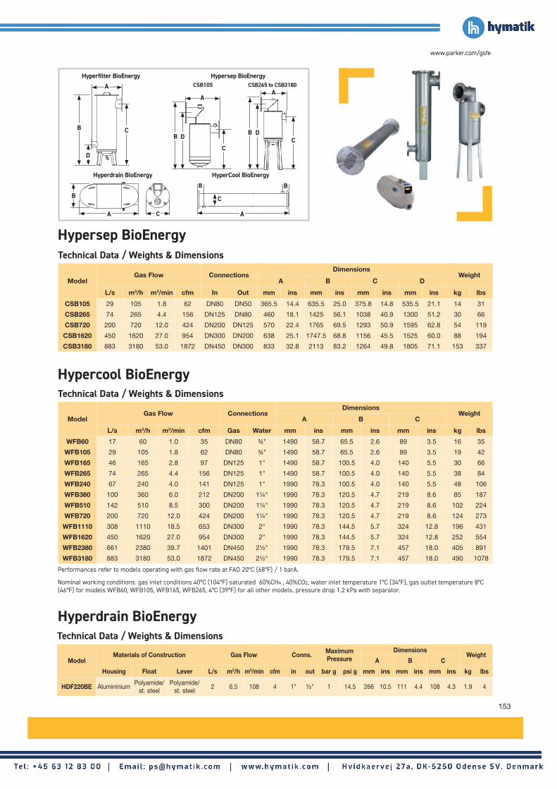
153
www.parker.com/gsfe
Hypercool BioEnergyTechnical Data / Weights & Dimensions
ModelGas Flow Connections
DimensionsWeight
A B C
L/s m3/h m3/min cfm Gas Water mm ins mm ins mm ins kg lbs
WFB60 17 60 1.0 35 DN80 ¾" 1490 58.7 65.5 2.6 89 3.5 16 35
WFB105 29 105 1.8 62 DN80 ¾" 1490 58.7 65.5 2.6 89 3.5 19 42
WFB165 46 165 2.8 97 DN125 1" 1490 58.7 100.5 4.0 140 5.5 30 66
WFB265 74 265 4.4 156 DN125 1" 1490 58.7 100.5 4.0 140 5.5 38 84
WFB240 67 240 4.0 141 DN125 1" 1990 78.3 100.5 4.0 140 5.5 48 106
WFB360 100 360 6.0 212 DN200 1¼" 1990 78.3 120.5 4.7 219 8.6 85 187
WFB510 142 510 8.5 300 DN200 1¼" 1990 78.3 120.5 4.7 219 8.6 102 224
WFB720 200 720 12.0 424 DN200 1¼" 1990 78.3 120.5 4.7 219 8.6 124 273
WFB1110 308 1110 18.5 653 DN300 2" 1990 78.3 144.5 5.7 324 12.8 196 431
WFB1620 450 1620 27.0 954 DN300 2" 1990 78.3 144.5 5.7 324 12.8 252 554
WFB2380 661 2380 39.7 1401 DN450 2½" 1990 78.3 179.5 7.1 457 18.0 405 891
WFB3180 883 3180 53.0 1872 DN450 2½" 1990 78.3 179.5 7.1 457 18.0 490 1078
Performances refer to models operating with gas flow rate at FAD 20°C (68°F) / 1 barA.
Nominal working conditions: gas inlet conditions 40°C (104°F) saturated 60%CH4 , 40%CO2, water inlet temperature 1°C (34°F), gas outlet temperature 8°C (46°F) for models WFB60, WFB105, WFB165, WFB265, 4°C (39°F) for all other models. pressure drop 1.2 kPa with separator.
CSB105 CSB265 to CSB3180
Technical Data / Weights & Dimensions
ModelMaterials of Construction Gas Flow Conns. Maximum
PressureDimensions
WeightA B C
Housing Float Lever L/s m3/h m3/min cfm in out bar g psi g mm ins mm ins mm ins kg lbs
HDF220BE AlumininiumPolyamide/
st. steelPolyamide/
st. steel2 6.5 108 4 1" ½" 1 14.5 266 10.5 111 4.4 108 4.3 1.9 4
Hypersep BioEnergyTechnical Data / Weights & Dimensions
ModelGas Flow Connections
DimensionsWeight
A B C D
L/s m3/h m3/min cfm In Out mm ins mm ins mm ins mm ins kg lbs
CSB105 29 105 1.8 62 DN80 DN50 365.5 14.4 635.5 25.0 375.8 14.8 535.5 21.1 14 31
CSB265 74 265 4.4 156 DN125 DN80 460 18.1 1425 56.1 1038 40.9 1300 51.2 30 66
CSB720 200 720 12.0 424 DN200 DN125 570 22.4 1765 69.5 1293 50.9 1595 62.8 54 119
CSB1620 450 1620 27.0 954 DN300 DN200 638 25.1 1747.5 68.8 1156 45.5 1525 60.0 88 194
CSB3180 883 3180 53.0 1872 DN450 DN300 833 32.8 2113 83.2 1264 49.8 1805 71.1 153 337
Hyperdrain BioEnergy
Hypersep BioEnergyHyperfilter BioEnergy
Hyperdrain BioEnergy HyperCool BioEnergy
A
C
D
B
A C
B
A
B B
C
CB
A
DB D
C
A

154
Replacement Filter Elements and Maintenance KitsFor Legacy Parker domnick hunter Products
Replacement Filter Elements and Maintenanace Kits
Filter Model Replacement Element
AO005 005AO
AO010 010AO
AO015 015AO
AO020 020AO
AO025 025AO
AO030 030AO
AO035 035AO
AO040 040AO
AO045 045AO
AO050 050AO
AO055 055AO
AO060 060AO requires 3 per filter
AA005 005AA
AA010 010AA
AA015 015AA
AA020 020AA
AA025 025AA
AA030 030AA
AA035 035AA
AA040 040AA
AA045 045AA
AA050 050AA
AA055 055AA
AA060 060AA requires 3 per filter
ACS005 005ACS
ACS010 010ACS
ACS015 015ACS
ACS020 020ACS
ACS025 025ACS
ACS030 030ACS
ACS035 035ACS
ACS040 040ACS
ACS045 045ACS
ACS050 050ACS
ACS055 055ACS
ACS060 060ACS requires 3 per filter
OIL-Xplus Advantage ElementsFilter Model Replacement Element
AO-0003G K003AO
AO-0009G K009AO
AO-0017G K017AO
AO-0030G K030AO
AO-0058G K058AO
AO-0080G K145AO
AO-0125G K145AO
AO-0145G K145AO
AO-0205G K220AO
AO-0220G K220AO
AO-0330G K330AO
AO-0405G K430AO
AO-0430G K430AO
AO-0620G K620AO
AO-1000G K330AO requires 3 per filter
AA-0003G K003AA
AA-0009G K009AA
AA-0017G K017AA
AA-0030G K030AA
AA-0058G K058AA
AA-0080G K145AA
AA-0125G K145AA
AA-0145G K145AA
AA-0205G K220AA
AA-0220G K220AA
AA-0330G K330AA
AA-0405G K430AA
AA-0430G K430AA
AA-0620G K620AA
AA-1000G K330AA requires 3 per filter
ACS-0009G K009ACS
ACS-0017G K017ACS
ACS-0030G K030ACS
ACS-0058G K058ACS
ACS-0080G K145ACS
ACS-0125G K145ACS
ACS-0145G K145ACS
ACS-0205G K220ACS
ACS-0220G K220ACS
ACS-0330G K330ACS
ACS-0405G K430ACS
ACS-0430G K430ACS
ACS-0620G K620ACS
ACS-1000GK330ACS requires 3 per filter
Advantage Elements
OIL-XplusCombination Elements
OIL-X EVOLUTIONCombination Elements
OIL-X EVOLUTIONElements
Model Maintenance Kit No. Required
OVR100E 100OVR 1
OVR150H 100OVR 2
OVR200H 100OVR 4
OVR250J 100OVR 6
OIL-X EVOLUTION OVR Maintenance Kits
Filter Model Replacement Elements
AC-0006GK009AA
K006AC
AC-0013GK017AA
K013AC
AC-0025GK030AA
K025AC
AC-0040GK058AA
K040AC
AC-0065GK145AA
K065AC
AC-0085GK145AA
K085AC
Filter Model Replacement Elements
AC010010AA
010AC
AC015015AA
015AC
AC020020AA
020AC
AC025D025AA
025DAC
AC025E025AA
025EAC
AC030030AA
030AC

155
www.parker.com/gsfe
PCO2 MKI Maintenance KitsProduct Type Model Filter Type Maintenance Kit
Maxi PCO2 PCO2-1- 20 (300) OIL-Xplus MAKPCO2-1-20
Maxi PCO2 PCO2-2-20 (300) OIL-Xplus MAKPC02-2-20
Maxi PCO2 PCO2-3-20 (300) OIL-Xplus MAKPC02-3-20
Maxi PCO2 MPlus 4000 20 (300) OIL-Xplus MAK-MPLUS4000-20
Maxi PCO2 MPlus 6000 20 (300) OIL-Xplus MAK-MPLUS6000-20
Maxi PCO2 MPlus 8000 20 (300) OIL-Xplus MAK-MPLUS8000-20
Maxi PCO2 MPlus 10000 20 (300) OIL-Xplus MAK-MPLUS10000-20
Mplus PCO2 PCO2-0-20 (300) OIL-X EVOLUTION MAKEPC02-0-20
Mplus PCO2 PCO2-1-20 (300) OIL-X EVOLUTION MAKEPC02-1-20
Mplus PCO2 PCO2-2-20 (300) OIL-X EVOLUTION MAKEPC02-2-20
Mplus PCO2 PCO2-3-20 (300) OIL-X EVOLUTION MAKEPC02-3-20
Mplus PCO2 MPlus 4000 20 (300) OIL-X EVOLUTION MAKE-MPLUS4000-20
Mplus PCO2 MPlus 6000 20 (300) OIL-X EVOLUTION MAKE-MPLUS6000-20
Mplus PCO2 MPlus 8000 20 (300) OIL-X EVOLUTION MAKE-MPLUS8000-20
Mplus PCO2 MPlus 10000 20 (300) OIL-X EVOLUTION MAKE-MPLUS10000-20
Maxi PCO2 PCO2-0-24 (350) OIL-Xplus MAKPCO2-0-24
Maxi PCO2 PCO2-1-24 (350) OIL-Xplus MAKPCO2-1-24
Maxi PCO2 PCO2-2-24 (350) OIL-Xplus MAKPC02-2-24
Maxi PCO2 PCO2-3-24 (350) OIL-Xplus MAKPC02-3-24
Maxi PCO2 MPlus 4000 24 (350) OIL-Xplus MAK-MPLUS4000-24
Maxi PCO2 MPlus 6000 24 (350) OIL-Xplus MAK-MPLUS6000-24
Maxi PCO2 MPlus 8000 24 (350) OIL-Xplus MAK-MPLUS8000-24
Maxi PCO2 MPlus 10000 24 (350) OIL-Xplus MAK-MPLUS10000-20
Model Quantity Required Part Number
SE2010 1 ESMK1
SE2015 1 ESMK1
SE2030/SE2030P 2 ESMK1
ES36 1 ESMK1
ES90 1 ESMK1
ES125 1 ESMK2
ES250 2 ESMK2
ES500 1 ESMK3
ES1000 2 ESMK3
SE and ES Oil / Water Separator Maintenance Kits

156
GL and GL Plus ElementsFilter Model Replacement Element
GL2A / GL2AP CP1008A
GL2VL CP1008ZL
GL2ZL / GL2ZLP CP1008ZL
GL2XL / GL2XLP CP1008XL
GL3A / GL3AP CP2010A
GL3VL CP2010ZL
GL3ZL / GL3ZLP CP2010ZL
GL3XL / GL3XLP CP2010XL
GL7A / GL7AP CP2020A
GL7VL CP2020ZL
GL7ZL / GL7ZLP CP2020ZL
GL7XL / GL7XLP CP2020XL
GL9A / GL9AP CP3025A
GL9VL CP3025ZL
GL9ZL / GL9ZLP CP3025ZL
GL9XL / GL9XLP CP3025XL
GL11A / GL11AP CP3040A
GL11VL CP3040ZL
GL11ZL / GL11ZLP CP3040ZL
GL11XL / GL11XLP CP3040XL
GL12A / GL12AP CP4040A
GL12VL CP4040ZL
GL12ZL / GL12ZLP CP4040ZL
GL12XL / GL12XLP CP4040XL
GL13A / GL13AP CP4050A
GL13VL CP4050VL
GL13ZL / GL13ZLP CP4050ZL
GL13XL / GL13XLP CP4050XL
GL14A / GL14AP CP4065A
GL14VL CP4065ZL
GL14ZL / GL14ZLP CP4065ZL
GL14XL / GL14XLP CP4065XL
GL17A / GL17AP CP5065A
GL17VL CP5065ZL
GL17ZL / GL17ZLP CP5065ZL
GL17XL / GL17XLP CP5065XL
GL19A / GL19AP CP5080A
GL19VL CP5080ZL
GL19ZL / GL19ZLP CP5080ZL
GL19XL / GL19XLP CP5080XL
G ElementsFilter Model Replacement Element
GH2A 1030A
GH2V 1030ZP
GH2XP 1030XP
G2ZP 1030ZP
G3A 1050A
G3V 1050ZP
G3XP 1050XP
G3ZP 1050ZP
G5A 1070A
G5V 1070ZP
G5XP 1070XP
G5ZP 1070ZP
G7A 1140A
G7V 1140ZP
G7XP 1140XP
G7ZP 1140ZP
G9A 2010A
G9V 2010ZP
G9XP 2010XP
G9ZP 2010ZP
G11A 2020A
G11V 2020ZP
G11XP 2020XP
G11ZP 2020ZP
G12A 2030A
G12V 2030ZP
G12XP 2030XP
G12ZP 2030ZP
G13A 2050A
G13V 2050ZP
G13XP 2050XP
G13ZP 2050ZP
G14A 3050A
G14V 3050ZP
G14XP 3050XP
G14ZP 3050ZP
G17A 5060A
G17V 5060ZP
G17XP 5060XP
G17ZP 5060ZP
G18A 3075A
G18V 3075ZP
G18XP 3075XP
G18ZP 3075ZP
G19A 5075A
G19V 5075ZP
G19XP 5075XP
G19ZP 5075ZP
LV Series Paint CompatibleFilter Model Part Number
G2A/LV 1030A/LV
G2XPH/LV 1030XP/LV
G2ZPH/LV 1030ZP/LV
G3A/LV 1050A/LV
G3XPDH/LV 1050XP/LV
G3ZPDH/LV 1050ZP/LV
G5A/LV 1070A/LV
G5XPDH/LV 1070XP/LV
G5ZPDH/LV 1070ZP/LV
G7A/LV 1140A/LV
G7XPDH/LV 1140XP/LV
G7ZPDH/LV 1140ZP/LV
G9A/LV 2010A/LV
G9XPDH/LV 2010XP/LV
G9ZPDH/LV 2010ZP/LV
Replacement Filter Elements and Maintenanace Kits
Replacement Filter Elements For Legacy Parker Zander Products

157
www.parker.com/gsfe

158
Europe, Middle East, AfricaAE – United Arab Emirates, Dubai Tel: +971 4 8127100 [email protected]
AT – Austria, St. Florian Tel: +43 (0)7224 66201 [email protected]
AZ – Azerbaijan, Baku Tel: +994 50 2233 458 [email protected]
BE/NL/LU – Benelux, Hendrik Ido Ambacht Tel: +31 (0)541 585 000 [email protected]
BG – Bulgaria, Sofia Tel: +359 2 980 1344 [email protected]
BY – Belarus, Minsk Tel: +48 (0)22 573 24 00 [email protected]
CH – Switzerland, Etoy Tel: +41 (0)21 821 87 00 [email protected]
CZ – Czech Republic, Klecany Tel: +420 284 083 111 [email protected]
DE – Germany, Kaarst Tel: +49 (0)2131 4016 0 [email protected]
DK – Denmark, Ballerup Tel: +45 43 56 04 00 [email protected]
ES – Spain, Madrid Tel: +34 902 330 001 [email protected]
FI – Finland, Vantaa Tel: +358 (0)20 753 2500 [email protected]
FR – France, Contamine s/Arve Tel: +33 (0)4 50 25 80 25 [email protected]
GR – Greece, Piraeus Tel: +30 210 933 6450 [email protected]
HU – Hungary, Budaörs Tel: +36 23 885 470 [email protected]
IE – Ireland, Dublin Tel: +353 (0)1 466 6370 [email protected]
IL – Israel Tel: +39 02 45 19 21 [email protected]
IT – Italy, Corsico (MI) Tel: +39 02 45 19 21 [email protected]
KZ – Kazakhstan, Almaty Tel: +7 7273 561 000 [email protected]
NO – Norway, Asker Tel: +47 66 75 34 00 [email protected]
PL – Poland, Warsaw Tel: +48 (0)22 573 24 00 [email protected]
PT – Portugal Tel: +351 22 999 7360 [email protected]
RO – Romania, Bucharest Tel: +40 21 252 1382 [email protected]
RU – Russia, Moscow Tel: +7 495 645-2156 [email protected]
SE – Sweden, Spånga Tel: +46 (0)8 59 79 50 00 [email protected]
SK – Slovakia, Banská Bystrica Tel: +421 484 162 252 [email protected]
SL – Slovenia, Novo Mesto Tel: +386 7 337 6650 [email protected]
TR – Turkey, Istanbul Tel: +90 216 4997081 [email protected]
UA – Ukraine, Kiev Tel: +48 (0)22 573 24 00 [email protected]
UK – United Kingdom, Warwick Tel: +44 (0)1926 317 878 [email protected]
ZA – South Africa, Kempton Park Tel: +27 (0)11 961 0700 [email protected]
Parker Worldwide
North AmericaCA – Canada, Milton, Ontario Tel: +1 905 693 3000
US – USA, Cleveland Tel: +1 216 896 3000
Asia PacificAU – Australia, Castle Hill Tel: +61 (0)2-9634 7777
CN – China, Shanghai Tel: +86 21 2899 5000
HK – Hong Kong Tel: +852 2428 8008
IN – India, Mumbai Tel: +91 22 6513 7081-85
JP – Japan, Tokyo Tel: +81 (0)3 6408 3901
KR – South Korea, Seoul Tel: +82 2 559 0400
MY – Malaysia, Shah Alam Tel: +60 3 7849 0800
NZ – New Zealand, Mt Wellington Tel: +64 9 574 1744
SG – Singapore Tel: +65 6887 6300
TH – Thailand, Bangkok Tel: +662 186 7000
TW – Taiwan, Taipei Tel: +886 2 2298 8987
South AmericaAR – Argentina, Buenos Aires Tel: +54 3327 44 4129
BR – Brazil, Sao Jose dos Campos Tel: +55 800 727 5374
CL – Chile, Santiago Tel: +56 2 623 1216
MX – Mexico, Toluca Tel: +52 72 2275 4200
EMEA Product Information CentreFree phone: 00 800 27 27 5374(from AT, BE, CH, CZ, DE, DK, EE, ES, FI, FR, IE, IL, IS, IT, LU, MT, NL, NO, PL, PT, RU, SE, SK, UK, ZA)
US Product Information CentreToll-free number: 1-800-27 27 537
www.parker.com/gsfe
CATPRODUCTSGSFE2020-00-EN© 2020 Parker Hannifin Corporation. All rights reserved.