Embed Size (px)
Citation preview

This reference material is provided by TMG Test Equipment,VIAVI’s only Master Distributor for Contractors in Australia
Enabling Australia’s Field Technicians to build, troubleshootand maintain better communications networks.
Industry Best Pricing Finance Available
Short to Medium Project-Based Rental Solutions
Dedicated Technical & After-Sales Support
In-house Diagnostics, Repair & NATA Calibration Laboratory
FREECALL 1800 680 680
WEBSITE: www.jdsu.com
COMMUNICATIONS TEST & MEASUREMENT SOLUTIONS
PCM-40 PCM Channel AnalyzerPCS-40 PCM Channel Selector
For codec and line card tests on PCM multiplexers and digital exchanges
Determining long-term stability (aging)
Communications systems and network elements are subjected to a wide variety of environmental influences which adversely affect component performance to a greater or lesser degree. If the effect of such influences on, say, system gain are to be recorded, the PCM-40 provides support for this application. During system line-up, the results and instrument configuration are stored so that they can easily be recalled. In the subsequent measurement, the results are displayed within the tolerance mask and the new result trace is superimposed. The instrument then determines the difference between the two measurements so that the deviation can be seen directly.
Status of connected test signal
The PCM-40 continuously monitors the connected test signal during the measurement and dis-plays the result on the front panel and in detail on the screen. This keeps you informed of the status and prevents incorrect interpretation of the measurement results.
Storage of measurement configurations
The test equipment settings required for routine or specialized manually-performed measure-ments, along with explanatory comments, can simply be stored by the PCM-40. The number of setups which can be stored is limited only by the system resources of the computer you are using.
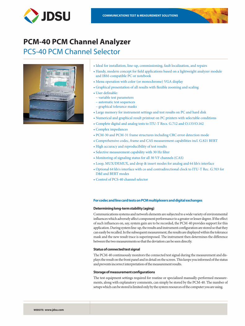
• Ideal for installation, line-up, commissioning, fault localization, and repairs• Handy, modern concept for field applications based on a lightweight analyzer module
and IBM-compatible PC or notebook• Menu operation with color (or monochrome) VGA display• Graphical presentation of all results with flexible zooming and scaling• User definable:
– variable test parameters – automatic test sequences – graphical tolerance masks
• Large memory for instrument settings and test results on PC and hard disk• Numerical and graphical result printout on PC printers with selectable conditions• Complete digital and analog tests to ITU-T Recs. G.712 and O.133/O.162• Complex impedances• PCM-30 and PCM-31 frame structures including CRC error detection mode• Comprehensive codec, frame and CAS measurement capabilities incl. G.821 BERT• High accuracy and reproducibility of test results• Selective measurement capability with 30 Hz filter• Monitoring of signaling status for all 30 VF channels (CAS)• Loop, MUX/DEMUX, and drop & insert modes for analog and 64 kb/s interface• Optional 64 kb/s interface with co and contradirectional clock to ITU-T Rec. G.703 for
D&I and BERT modes• Control of PCS-40 channel selector
PCM-40 PCM Channel Analyzer
2
Automatic test sequences
You can produce automatic test sequences by combining several test configurations together from the range of setups which you have stored. All of the measurement functions included in the PCM-40 along with any variations in test variables, parameters and tolerance limits, can be used for this in any order required. The sequence can be programmed to stop if an incorrect result is obtained or before each dif-ferent measurement task.
Monitoring digital paths in through mode or via high-impedance taps
For long-term monitoring of 2 Mb/s paths, the circuit can be looped-through the PCM-40 transparently or tapped via a high impedance monitor point. If the power supply fails during loop-through measurements , the signal path is not interrupted. The following measurements can be performed:• Frame monitoring with FAS errors recorded
as histograms• Level, frequency and coder level monitoring
including audio monitoring in a selected channel
• Recording of byte changes in the selected frame or data channel
• Signaling status display for individual chan-nels
Quality monitoring in an idle channel
Facilities for monitoring the quality of PCM systems which do not use CRC frames are lim-ited to monitoring the frame alignment signals. The PCM-40 can, however, perform a loop-back or end-to-end measurement to ITU-T G.821 in an idle channel. The instrument transmits a test pattern which it then evalu-ates. The results can be shown as a table or as an error histogram.
PCM-40 as an automated measuring system
When testing PCM multiplexers, the PCS-40 channel selector connects up to 30 analog TX and RX channels sequentially to the PCM-40 analog test ports. The PCS-40 channel selector allows return loss and longitudinal conversion loss measurements on individual VF channels using the built-in bridges. Also test needing D.C. loop holding circuit or feeding bridge are possible. The result is a flexible and powerful test system well suited to production, installa-tion and maintenance of 2 Mb/s multiplexers.
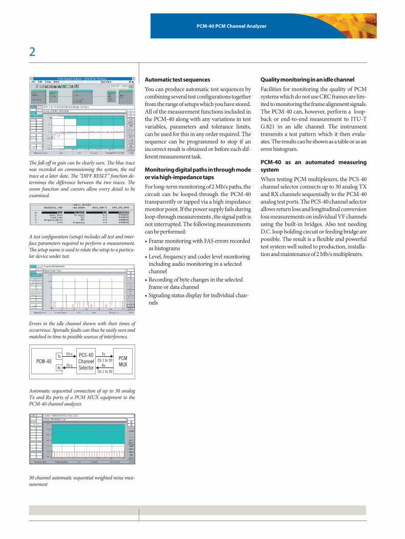
The fall-off in gain can be clearly seen. The blue trace was recorded on commissioning the system, the red trace at a later date. The “DIFF RESLT” function de-termines the difference between the two traces. The zoom function and cursors allow every detail to be examined.
A test configuration (setup) includes all test and inter-face parameters required to perform a measurement. The setup name is used to relate the setup to a particu-lar device under test.
Errors in the idle channel shown with their times of occurrence. Sporadic faults can thus be easily seen and matched in time to possible sources of interference.
Automatic sequential connection of up to 30 analog Tx and Rx ports of a PCM MUX equipment to the PCM-40 channel analyzer.
30 channel automatic sequential weighted noise mea-surement
PCM-40PCS-40ChannelSelector
PCMMUX
Tx Tx
RxRx
Ch x
Ch xCh 1 to 30
Ch 1 to 30
PCM-40 PCM Channel Analyzer
3
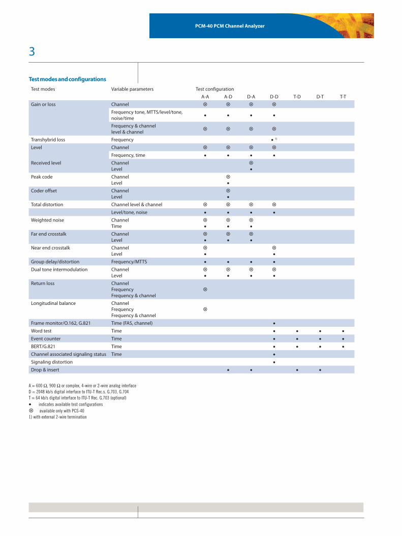
Test modes and configurations
Test modes Variable parameters Test configuration
A-A A-D D-A D-D T-D D-T T-T
Gain or loss Channel
Frequency tone, MTTS/level/tone, noise/time
• • • •
Frequency & channellevel & channel
Transhybrid loss Frequency • 1)
Level Channel
Frequency, time • • • •Received level Channel
Level•
Peak code ChannelLevel
•
Coder offset ChannelLevel
•
Total distortion Channel level & channel
Level/tone, noise • • • •Weighted noise Channel
Time•
•
•
Far end crosstalk ChannelLevel
•
•
•
Near end crosstalk ChannelLevel
•
•
Group delay/distortion Frequency/MTTS • • • •Dual tone intermodulation Channel
Level•
•
•
•
Return loss ChannelFrequencyFrequency & channel
Longitudinal balance ChannelFrequencyFrequency & channel
Frame monitor/O.162, G.821 Time (FAS, channel) •Word test Time • • • •Event counter Time • • • •BERT/G.821 Time • • • •Channel associated signaling status Time •Signaling distortion •Drop & insert • • • •
A = 600 W, 900 W or complex, 4-wire or 2-wire analog interfaceD = 2048 kb/s digital interface to ITU-T Rec.s. G.703, G.704T = 64 kb/s digital interface to ITU-T Rec. G.703 (optional)• indicates available test configurations available only with PCS-401) with external 2-wire termination
4
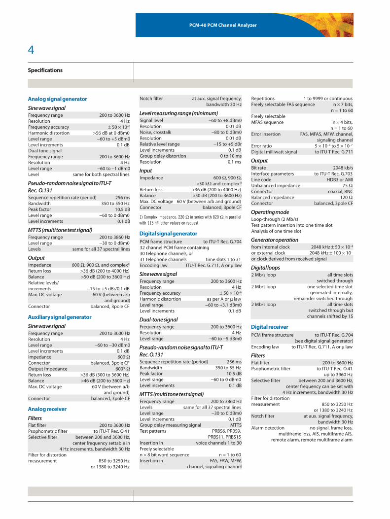
Specifications
PCM-40 PCM Channel Analyzer
Analog signal generator
Sine wave signalFrequency range 200 to 3600 HzResolution 4 HzFrequency accuracy ± 50 × 10-6
Harmonic distortion >56 dB at 0 dBm0Level range -60 to +5 dBm0Level increments 0.1 dBDual tone signalFrequency range 200 to 3600 HzResolution 4 HzLevel range -60 to -1 dBm0Level same for both spectral lines
Pseudo-random noise signal to ITU-T Rec. O.131Sequence repetition rate (period) 256 msBandwidth 350 to 550 HzPeak factor 10.5 dBLevel range -60 to 0 dBm0Level increments 0.1 dB
MTTS (multi tone test signal)Frequency range 200 to 3860 HzLevel range -30 to 0 dBm0Levels same for all 37 spectral lines
OutputImpedance 600 W, 900 W, and complex1)
Return loss >36 dB (200 to 4000 Hz)Balance >50 dB (200 to 3600 Hz)Relative levels/increments -15 to +5 dBr/0.1 dBMax. DC voltage 60 V (between a/b and ground)Connector balanced, 3pole CF
Auxiliary signal generator
Sine wave signalFrequency range 200 to 3600 HzResolution 4 HzLevel range -60 to -30 dBm0Level increments 0.1 dBImpedance 600 WConnector balanced, 3pole CFOutput Impedance 600* WReturn loss >36 dB (300 to 3600 Hz)Balance >46 dB (200 to 3600 Hz)Max. DC voltage 60 V (between a/b and ground)Connector balanced, 3pole CF
Analog receiver
FiltersFlat filter 200 to 3600 HzPsophometric filter to ITU-T Rec. O.41Selective filter between 200 and 3600 Hz, center frequency settable in 4 Hz increments, bandwidth 30 HzFilter for distortionmeasurement 850 to 3250 Hz or 1380 to 3240 Hz
Notch filter at aux. signal frequency, bandwidth 30 Hz
Level measuring range (minimum)Signal level -60 to +8 dBm0Resolution 0.01 dBNoise, crosstalk -80 to 0 dBm0Resolution 0.01 dBRelative level range -15 to +5 dBrLevel increments 0.1 dBGroup delay distortion 0 to 10 msResolution 0.1 ms
InputImpedance 600 W, 900 W, >30 kW and complex1)
Return loss >36 dB (200 to 4000 Hz)Balance >50 dB (200 to 3600 Hz)Max. DC voltage 60 V (between a/b and ground)Connector balanced, 3pole CF
1) Complex impedance: 220 W in series with 820 W in parallel with 115 nF; other values on request
Digital signal generatorPCM frame structure to ITU-T Rec. G.70432 channel PCM frame containing30 telephone channels, or31 telephone channels time slots 1 to 31Encoding law ITU-T Rec. G.711, A or µ law
Sine wave signalFrequency range 200 to 3600 HzResolution 4 HzFrequency accuracy ± 50 × 10-6
Harmonic distortion as per A or µ lawLevel range -60 to +3.1 dBm0Level increments 0.1 dB
Dual-tone signalFrequency range 200 to 3600 HzResolution 4 HzLevel range -60 to -5 dBm0
Pseudo-random noise signal to ITU-T Rec. O.131Sequence repetition rate (period) 256 msBandwidth 350 to 55 HzPeak factor 10.5 dBLevel range -60 to 0 dBm0Level increments 0.1 dB
MTTS (multi tone test signal)Frequency range 200 to 3860 HzLevels same for all 37 spectral linesLevel range -30 to 0 dBm0Level increments 0.1 dBGroup delay measuring signal MTTSTest patterns PRBS6, PRBS9, PRBS11, PRBS15Insertion in voice channels 1 to 30Freely selectable n × 8 bit word sequence n = 1 to 60Insertion in FAS, FAW, MFW, channel, signaling channel
Repetitions 1 to 9999 or continuousFreely selectable FAS sequence n × 7 bits, n = 1 to 60Freely selectable MFAS sequence n × 4 bits, n = 1 to 60Error insertion FAS, MFAS, MFW, channel, signaling channelError ratio 5 × 10⁻³ to 5 × 10⁻⁷
Digital milliwatt signal to ITU-T Rec. G.711
OutputBit rate 2048 kb/sInterface parameters to ITU-T Rec. G.703Line code HDB3 or AMIUnbalanced impedance 75 WConnector coaxial, BNCBalanced impedance 120 WConnector balanced, 3pole CF
Operating modeLoop-through (2 Mb/s)Test pattern insertion into one time slotAnalysis of one time slot
Generator operationfrom internal clock 2048 kHz ± 50 × 10-6
or external clock 2048 kHz ± 100 × 10-
or clock derived from received signal
Digital loops2 Mb/s loop all time slots switched through2 Mb/s loop one selected time slot generated internally, remainder switched through2 Mb/s loop all time slots switched through but channels shifted by 15
Digital receiverPCM frame structure to ITU-T Rec. G.704 (see digital signal generator)Encoding law to ITU-T Rec. G.711, A or µ law
FiltersFlat filter 200 to 3600 HzPsophometric filter to ITU-T Rec. O.41 up to 3960 HzSelective filter between 200 and 3600 Hz, center frequency can be set with 4 Hz increments, bandwidth 30 HzFilter for distortion measurement 850 to 3250 Hz or 1380 to 3240 HzNotch filter at aux. signal frequency, bandwidth 30 HzAlarm detection no signal, frame loss, multiframe loss, AIS, multiframe AIS, remote alarm, remote multiframe alarm

5
Specifications
PCM-40 PCM Channel Analyzer
EvaluationBit error count, event count,recording of transients in digital words FAS, FAW, MFW, signaling channel, telephone channelTelephone channel r.m.s. valuemeasurement -80 to +6 dBm0ITU-T G.821 evaluation bit errors, FAS errorsError results displayed as histograms
InputBit rate 2048 kb/sInterface parameters to ITU-T Rec. G.703Line code HDB3 or AMIUnbalanced input impedance 75 W or >2 kWConnector coaxial, BNCBalanced input impedance 120 W or >2 kWConnector balanced, 3pole CFClock from received signalPulling range ± 100 × 10-6
Measurement interval 60 s to 72 hInstrument set-up memory depends on PC resources available
Automatic measurement sequencesIndividual measurements linkedto a sequence max. number depends on PC resources available
Result documentationResult output to external printerOutput in table or graph formatsResult output as ASCII file to diskResult in table format can be saved to disk with printout using DOS “PRINT” command.Result storage and test configuration storage depends on PC resources available.
Self-test and level calibrationTriggered automatically by opening the measure-ment menu
Codec interface/handset interfaceInput/output impedance 600 WConnector RJ11
64 kb/s interface (optional)Output/input to ITU-T Rec. G.703Modes codirectional, contradirectionalBalanced output 120 WConnector balanced, 3pole CFClock output 120 WConnector balanced, 3pole CF
General specifications
Control computer for PCM-40PC AT 486WIN 3.1, WIN 95, 98, NTmin. 600 kB free conventional memorymin. 256 kB free EMS memorymin. 40 MB free HD spaceVGA monitor (color or monochrome)serial or GPIB (National Instruments) interface
Communication interfaces for PCM-40Serial I (for computer control) RS232C/V.24Serial II (for modem connection) RS232C/V.24GPIB/<IEC 625> 8.5/IEEE-488.1-1978 (for computer control)
Power supplyExternal adapter with AC line cordAC supply 100 to 240 V, 50 to 60 HzPower consumption 25 VA
Ambient temperatureNominal range of use +5 to +45 °CLimits range of use (for 2 hours) 0 to +55 °CStorage and transport -40 to +70 °C
Air humidityNominal range of use 20 to 80 %,r.h. (<20 g/m3 absolute)
Dimensions(l × w × h in mm) 290 × 230 × 70Weight approx. 3.5 kg
Specifications for PCS-40 PCM
Channel SelectorTest ports (Ch x)Maximum level +20 dBmMax. DC voltage 60 V (between a/b and ground)Max. DC current 100 mAImpedance 600 WInsertion loss between test port and selected Tx/Rx port (200 Hz to 4 kHz) <0.02 dBConnector balanced, 3pole CF
Access ports (Ch 1 to Ch 30)Balanced through-switching of up to 30 VF channels in Tx and Rx directionsConnector DIN 41612 type socket, 64-way, femaleSwitching time <10 ms
Return loss measurementBuilt-in bridge for return loss measurements on a selectable VF channelMeasurement range 0 to 45 dBFrequency range 200 Hz to 4 kHzAccuracy 0 to 30 dB 1 dB 30 to 45 dB 2 dBReference impedance internal 600 W external (connected to auxiliary input) 600 to 900 WMax. input level 200 Hz to 300 Hz -6 dBm 300 Hz to 4 kHz 0 dBm
Longitudinal conversion loss (LCL) measurementBuilt-in bridge for LCL measurements accord-ing to ITU-T Rec. O.9 on a selectable VF channelMeasurement range 5 to 56 dBFrequency range 200 Hz to 4 kHzAccuracy 5 to 46 dB 1 dB 46 to 56 dB 2 dBTerminating impedance 600 WMax. input level -6 dBm
DC current loopTwo built-in current loops connected to each test portDC current <150 mAVoltage drop at 20 mA(100 mA) <5.5 V (<12 V)Output impedance(200 Hz to 4 kHz) approx. 30 kW
DC feeding bridgeTwo built-in current loops connected to each test portSupply voltage (It = 0) appprox. 30 VSupply current (Rt = 400 W) >20 mASupply current (Rt = 0 W) approx. 38 mAOutput impedance(200 Hz to 4 kHz) approx. 50 kWLCL (200 Hz to 4 kHz) >45 dB
Line status indication (TX and RX)Line feeding voltage onLine looped
Remote controlControl of all functions from PCM-40 Channel Analyzer or personal computer via GPIB/IEC625/IEEE488 interfaceInterface IEEE 488 connector
General specifications
Power supplyExternal adapter with AC line cordAC supply 100 to 240 V, 50 to 60 HzPower consumption 10 VA(One adapter can supply both the PCM-40 and PCS-40)
Ambient temperatureNominal range of use +5 to +45 °CLimits range of use (for 2 hours) 0 to +55 °CStorage and transport -40 to +70 °C
Air humidityNominal range of use 20 to 80 %,r.h. (<20 g/m3 absolute)
Dimensions(l × w × h in mm) 290 × 230 × 70Weight approx. 2 kg

All statements, technical information and recommendations related to the products herein are based upon infor-mation believed to be reliable or accurate. However, the accuracy or completeness thereof is not guaranteed, and no responsibility is assumed for any inaccuracies. The user assumes all risks and liability whatsoever in connec-tion with the use of a product or its applications. JDSU reserves the right to change at any time without notice the design, specifications, function, fit or form of its products described herein, including withdrawal at any time of a product offered for sale herein. JDSU makes no representations that the products herein are free from any intellectual property claims of others. Please contact JDSU for more information. JDSU and the JDSU logo are trademarks of JDS Uniphase Corporation. Other trademarks are the property of their respective holders. © 2006 JDS Uniphase Corporation. All rights reserved. 30137187 501 0707 PCM-PCS40.DS.CPO.TM.AE
Test & Measurement Regional Sales
NORTH AMERICATEL: 1 866 228 3762FAX: +1 301 353 9216
LATIN AMERICATEL:+55 11 5503 3800FAX:+55 11 5505 1598
ASIA PACIFICTEL:+852 2892 0990FAX:+852 2892 0770
EMEATEL:+49 7121 86 2222FAX:+49 7121 86 1222
WEBSITE: www.jdsu.com
PCM-40 PCM Channel Analyzer
EL 3039/01 PCM-40 Channel AnalyzerIncluding AC adapter, RS232C/V.24 cable and operation manual (in English)A separate PC is required for operation
EL 3039/60 Calibration report for PCM-40
EL 3039/20 PCS-40 Channel SelectorIncluding return loss and longitudinal conversion loss (LCL) measuring bridge, DC current loop and DC feeding bridge, cables for interconnection of PCM-40 and PCS-40, 64-way female connector set for accessing PCM MUX and operation manual (in English)
Options
EL 3039/01 64 kb/s interface(for codirectional/contradirectional clock) for BERT and D&I
EL 3039/02 Impedance modification(replaces complex impedance)
Accessories
EL3043/01 GH-1 DC Loop Holding/Line Feeding, OC Loop Holding ELH-2
EL 2237/01 Nylon carrying case(for PCM-40, Notebook PC and accessories)
EL 3039/203 64-way female connector set for PCS-40
EL 3039/201 IEEE interface cable for PCS-40
EL 3039/202 AC adapter for PCS-40
Documentation
EL 3039/83 Service manual for PCM/PCS-40 (in English)
Ordering information