Embed Size (px)
Citation preview
Comparison testing of shock versus vibration ESS systems
AUTHOR: Dr. Hong-sun Liu, Quanta Laboratories
Contributors: Larry Foshee, Motion Engineering
Ron Weglinski, Susan Mercovich, Greg Wilterdink, Transistor Devices Inc.
Mingwei Lu, Zhigang Gao, Xiaoqi Gou, Huawei Technologies Company
ABSTRACT
It is well known that environmental stress screening (ESS) is a very effective tool for improving product reliability; however, because of the high cost and long duration required for this process, most people still choose not to utilize this great tool in the manufacturing process. This author has developed a new ESS approach and equipment that will greatly reduce the time and cost for the ESS process. This approach is to screen the complete product/system once to find significant structural and interconnection problems and correct them, then to take the P.C. boards out of the chassis to screen them independently on a skewed (angled) fixture to achieve 3-directional input1. Since this system uses a controlled random vibration profile on an electro-dynamic shaker, it will not have the shock input problems of the pneumatic hammer system, which has very high energy at frequencies not normally seen by the product and not enough energy at low frequencies to screen out problems encountered during shipping, handling and operation. A direct comparison test is conducted on several different types of products; the effectiveness, screen time, and cost, as well as vibrational intensity needed for the process, are reported in detail.
ENVIRONMENTAL STRESS SCREEING SYSTEMS
1.1 Pneumatic Hammer
It is well known that Environmental Stress Screening (ESS) is a very effective tool to precipitate the weaknesses of a product. Currently however, the most available equipment for this process is the pneumatic hammer (shock) system
. The pneumatic hammer system consists of a flat table mounted on a set of springs, a bunch of
pneumatic hammers are attached to the table at different orientations as depicted in figure 1:
1.2 Skewed fixture ESS system
The author has developed a new ESS system that utilizes a skewed fixture together with an electromagnetic shaker system (or a hydraulic shaker system) in conjunction with a fast ramping chamber[Ref 1].
The principle of operation of the skewed fixture is that the test article is vibrated at a skewed angle;the unit will receive forces in all three orthogonal directions at the same time as shown in figure 2:

Fig. 1. Depiction of Pneumatic Hammer System
Fig. 2. Skewed Fixture ESS system
THE ADVANTAGES OF THE SKEWED FIXTURE SYSTEM
Frequency Control - The random vibration profile can be precisely controlled, i.e. it is able to cut off inappropriate high frequency energy while at the same time maintaining the low frequency energy needed to screen out damage that could be caused by shipping and operations in the real world.
Table Uniformity - The vibration intensity is uniform across the whole table because it has only one actuation device - the shaker.
Less Time and Money - All three axes are screened simultaneously on the skewed fixture, which saves test time and money.
These ESS systems apply very different technologies, and since the response of products to vibration or to shock are very different; but to date, the effectiveness and cost of screening by each system have not been compared. In order to evaluate the merits of these systems, such a comparison study has been performed by Quanta Laboratories. Quanta, in conjunction with three reliability conscious companies - Motion Engineering, Transistor Devices Inc., and a large network device company (who has asked to remain anonymous) established a joint project to perform HALT on three products of different sizes, a printed circuit board, a power supply and a large system (chassis). All three commercial products have previously gone through Highly Accelerated Life Test (HALT) on the pneumatic hammer system. Quanta’s responsible engineer and the technical team from each participating company worked together to ensure that the identical diagnostic system and vibration test conditions were used for the HALT comparison on each test unit. In order to make fair comparisons, the exact same model of each product was used in HALT testing on the new system as was tested in the previous HALT tests on the pneumatic hammer system. The major difference between the tests is that the vibration profile on the 5 to 500 Hzrange, (even though this system is capable of frequencies up to 3000 Hz). The reason we concentrated on these lower level frequencies is that the test units were commercial products; it is unlikely that these unitswill ever see vibration levels much higher than 500Hz in their operating or transportation lives. However, for certain products for aircraft, missiles, fiber optic devices, etc., we would choose a spectrum between 5~20 to 2000 Hz.
The two main differences between the skewed fixture system and the pneumatic hammer system are:
1. On the skewed fixture system, the spectrum can be precisely controlled, such that inappropriatehigh frequency energy can be removed and real-life low frequency energy can be correctly imposed in direct contrast to the pneumatic hammer systems
2. The vibration intensity across the skewed fixture is very uniform as opposed to the pneumatic hammer system, which has large variations across the table [Ref 2].
Because of these advantages, the skewed fixture system is able to precipitate defects at a much loweroverall vibration level in a much shorter time, thus increasing product throughput and reducing the cost of testing.
RESULTS OF COMPARISON TESTS
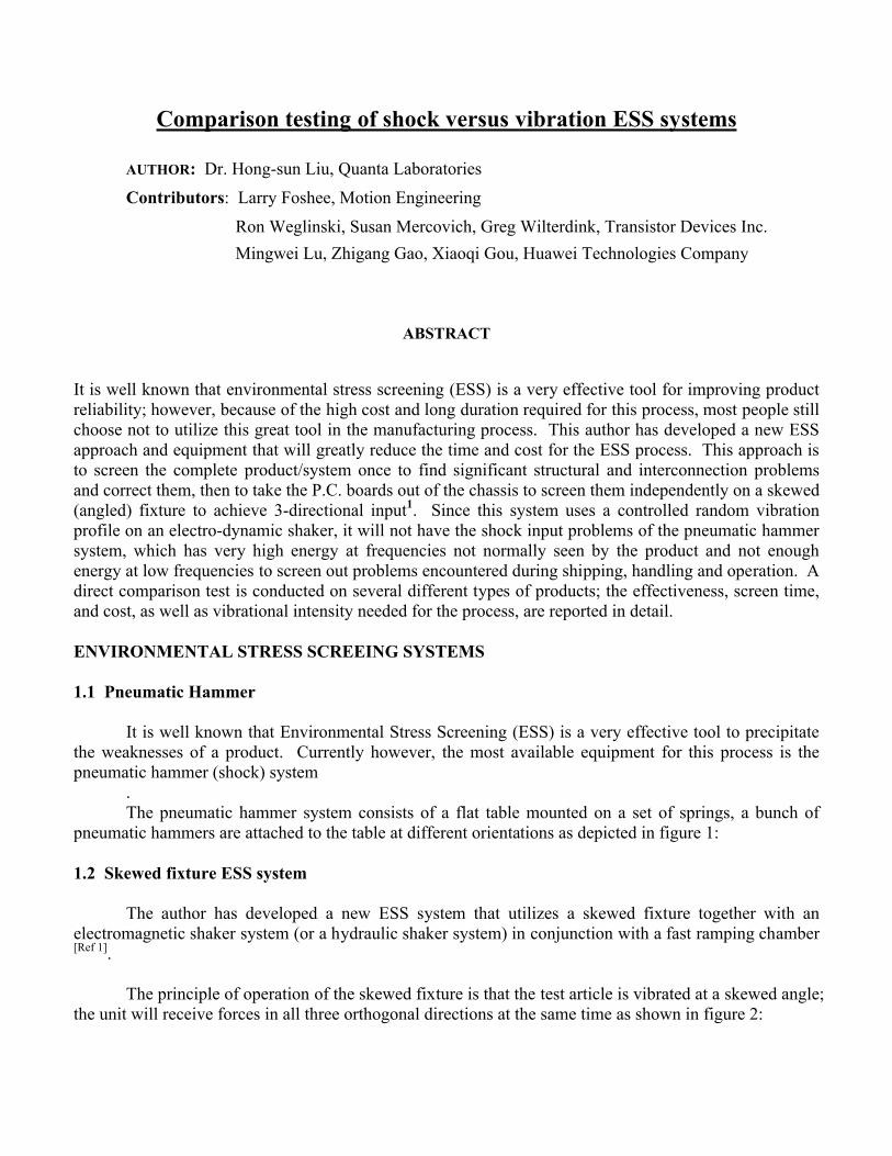
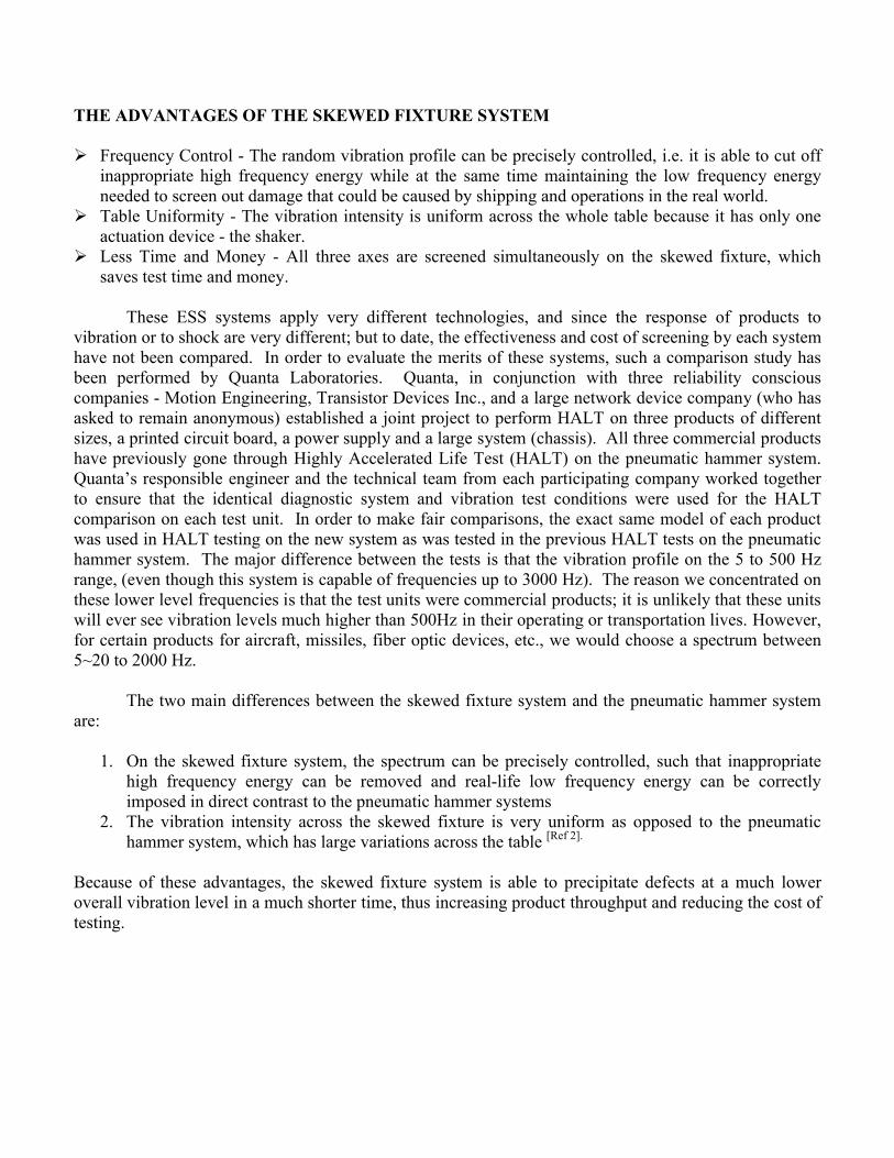
2.1 PRODUCT # 1 – SQID/Motion Printed Circuit Boards from Motion Engineering
Fig. 3. Unit on the skewed ESS system Fig. 4. Accelerometer mounted on the capacitor
The HALT test on the new system is designed to duplicate the original test on the pneumatic hammer system, except the frequency range for vibration is controlled over the range 5 to 500 Hz with a flat profile. The comparison unit did not go through thermal cycling with vibration when tested on the pneumatic hammer system, so for this comparison test, we also did not include temperature cycling as part of the test. The response accelerometer model(s) used and their locations were exactly the same in both tests. The results of the tests are listed in the following table:
ESS Testing System ED Shaker with Skewed Fixture Pneumatic Hammer System
Profile Flat Spectrum from 5-500 Hz Uncontrolled
Vibration Intensity Level (Grms)
5 5, 10, 15, 20, 25, 30, 35
Duration of Vibe at Each Level 5 min. 10 min
Failed at 5 Grms 35 Grms
Total Time to Failure (min.) 5 70
During both tests, the principal failure mode was that the same capacitor broke off. However, the pneumatic hammer system went to 35 Grms before this failure was found. Significantly, the
electromagnetic shaker ESS system uncovered the problem at 5 Grms. Note that the Grms values reported for the pneumatic hammer system are the mathematical average of the combined three-axis Grms values, filtered to a low frequency, usually to 2000 Hz, even though most of the energy for a pneumatic hammer table is between 2,000 to 25,000 Hz. Therefore, the Grms values seen by the product on the three axes are actually much higher than the calculated Grms values for the pneumatic hammer shock method. Thus, thecalculated 35 Grms value is much lower than the actual G-level input to the product. It should also benoted that the broken capacitor had an accelerometer mounted on it (see Fig. 4), but another identical capacitor, mounted immediately beside the broken one, did not break loose. Another test was performedon the new ESS system without mounting the accelerometer on the capacitor, and the capacitor did not break off. Clearly, it was mass loading by the accelerometer that caused the failure of the capacitor. In a later test, the new system found a real problem, which was a break in the Ethernet ring; however, after re-plugging the connecter, the unit recovered.
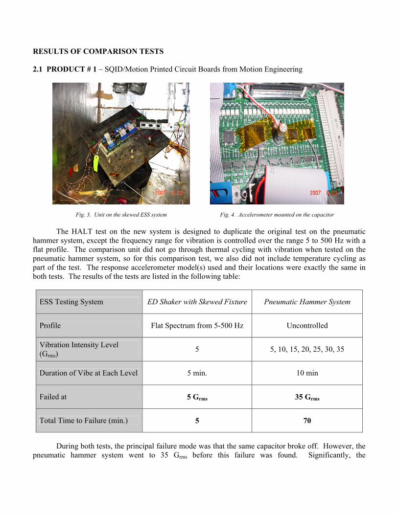
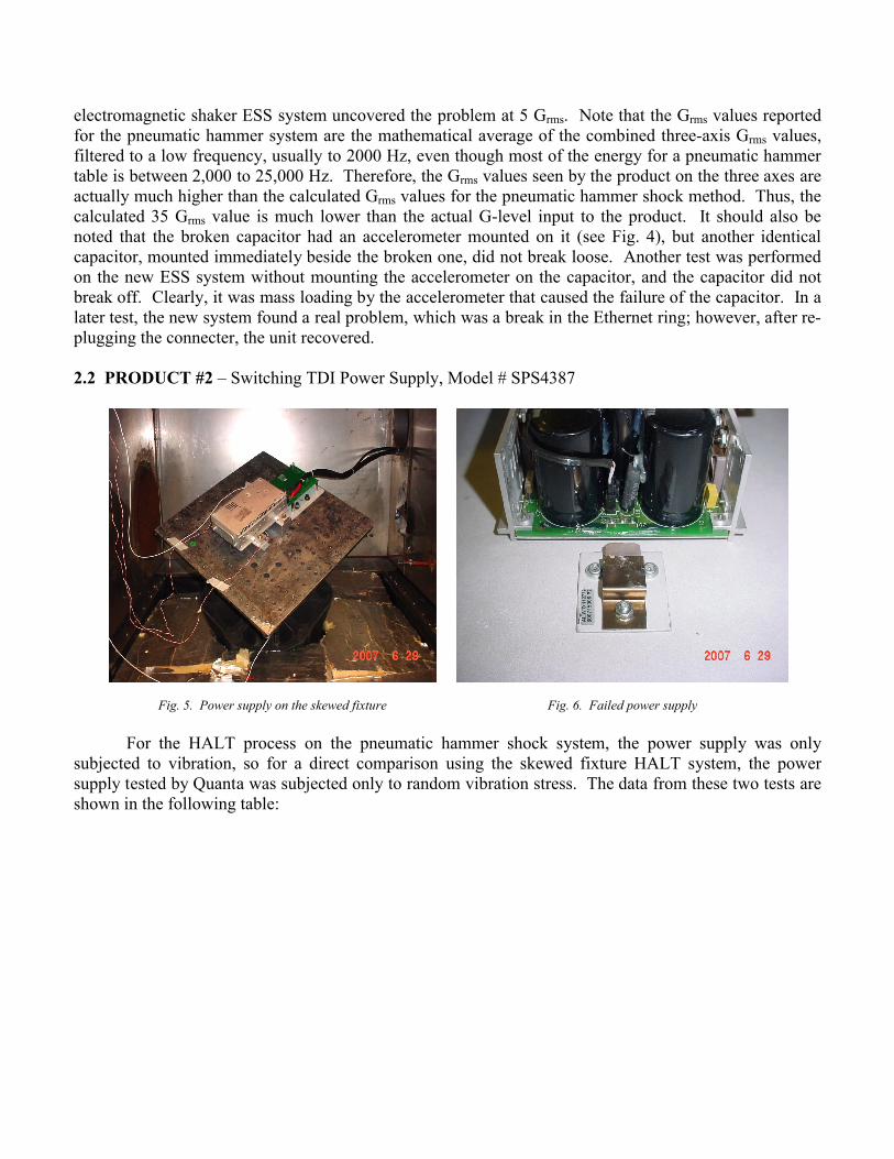
2.2 PRODUCT #2 – Switching TDI Power Supply, Model # SPS4387
Fig. 5. Power supply on the skewed fixture Fig. 6. Failed power supply
For the HALT process on the pneumatic hammer shock system, the power supply was only subjected to vibration, so for a direct comparison using the skewed fixture HALT system, the power supply tested by Quanta was subjected only to random vibration stress. The data from these two tests are shown in the following table:
ESS Testing System ED Shaker with Skewed Fixture Pneumatic Hammer System
Profile Flat Spectrum from 5-500 Hz Uncontrolled
Vibration Intensity Level (Grms) 1, 2, 3, 4, 5, 6, 7 1, 2, 3, 4, 5, 6, 7, 8, 9, 10
Duration of Vibe at Each Level 5 min.20 min. at 1~5 Grms; 30 min.
at 6~10 Grms
Failed at 7 Grms 10 Grms
Total Time to Failure (min.) 32 244
The same weakness was found in both tests (mechanical fatigue failure of the FET transistor); however, the pneumatic hammer ESS system required vibration steps up to 10 Grms and took 244 minutes to precipitate the weakness. The new ESS system precipitated the same weakness at 7 Grms, and only took 32 minutes.
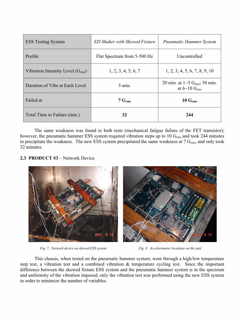
2.3 PRODUCT #3 – Network Device
Fig. 7. Network device on skewed ESS system Fig. 8. Accelerometer locations on the unit
This chassis, when tested on the pneumatic hammer system, went through a high/low temperature step test, a vibration test and a combined vibration & temperature cycling test. Since the importantdifference between the skewed fixture ESS system and the pneumatic hammer system is in the spectrumand uniformity of the vibration imposed, only the vibration test was performed using the new ESS systemin order to minimize the number of variables.

ESS Testing SystemED Shaker with Skewed
FixturePneumatic Hammer
System
Profile Flat Spectrum from 5-500 Hz Uncontrolled
Vibration Intensity Level (Grms) 1, 2, 3, 4, 5, 6, 7, 8, 102, 3, 5, 10, 5, 15, 5, 10,
12.5, 15
Duration of Vibe at Each Level 3.5 min.20 min. at 1~5 Grms; 30
min. at 6~10 Grms
Failed at 7 & 10 Grms 15 Grms
Total Time to 1st & 2nd Failure (min.) 24.5 & 28 ?
When this unit was tested on the pneumatic hammer system, the power supply failed at 15 Grms,and no other failure modes were found. However, when Quanta used an electromagnetic shaker with the skewed fixture ESS system, we found the compact flash memory came loose at 7 Grms (a weakness not uncovered by the pneumatic hammer system). Then at 8 Grms, there was a failure of one of the power supplies, but it came back when the vibration was stopped. When the random vibration level was stepped up to 10 Grms, less than 10 seconds after the start of the vibration both power supplies failed and could not be revived. Because of different vibration imposition approaches taken for each test, it was not possible to compare the total time it took to propagate the weaknesses by each of the systems. But the whole ESS process including the high/low temperature tests took the pneumatic hammer system roughly 3 days. Ittook the new ESS system only about 24.5 minutes of vibration time to find the backed-out compact flash memory problem and 28 minutes to fail the power supplies. The time it took is considerably shorter than the pneumatic hammer system vibration time and also the failures were identified at a much lower vibration level.
2.4 Product #4 – Huawei Network Blades
The following series of tests were performed by Huawei in China. In order to have a one to one comparison of vibration effects, all testing was performed with no temperature cycles imposed. The results show that more problems were precipated by the ED shaker with skewed fixture in a much shorter time and much lower Grms levels than were found by the pneumatic hammer system. In addition, all the problems discovered by the pneumatic hammer system were also identified by the ED shaker with skewed fixture. More importantly, high percentage of problems found by the ED shaker with skewed fixture system occurred during actual shipping and/or operation. For the three products, the pneumatic hammer system found a total of 5 problems while only 2 showed up in the field. The ED shaker with skewed fixture found a total 30 problems and 21 showed up in the field.
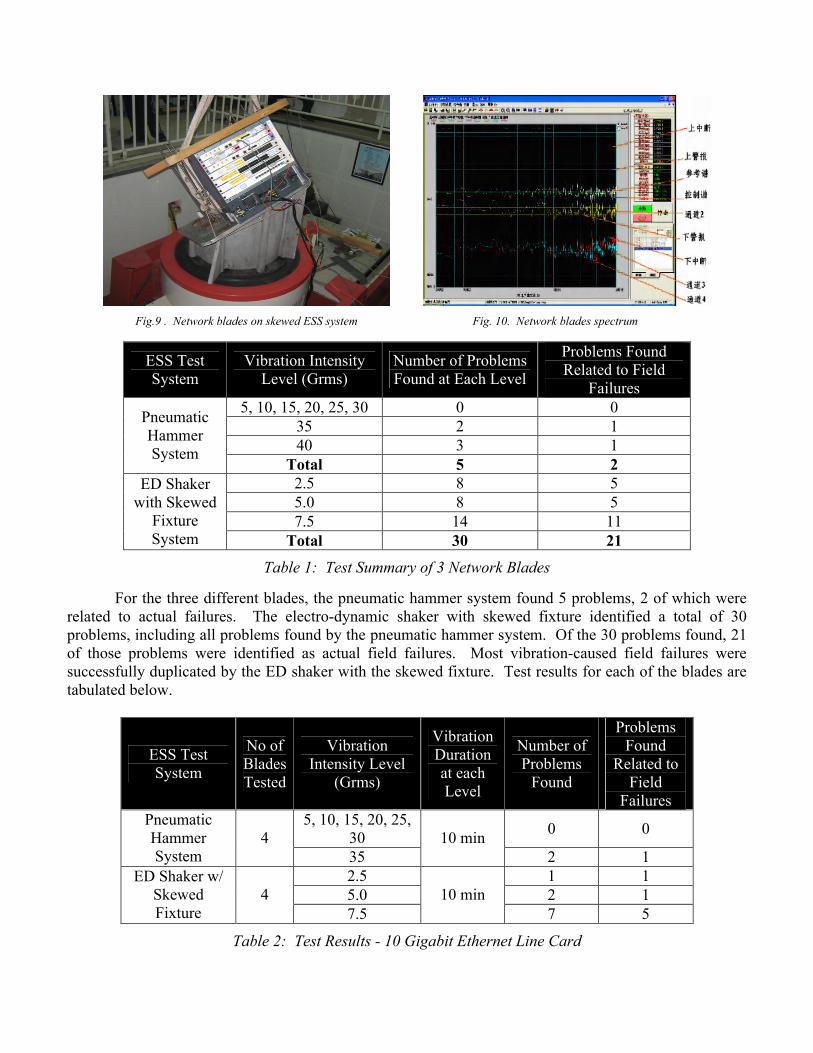
Fig.9 . Network blades on skewed ESS system Fig. 10. Network blades spectrum
ESS Test System
Vibration Intensity Level (Grms)
Number of Problems Found at Each Level
Problems Found Related to Field
Failures5, 10, 15, 20, 25, 30 0 0
35 2 140 3 1
Pneumatic Hammer System
Total 5 22.5 8 55.0 8 57.5 14 11
ED Shaker with Skewed
Fixture System Total 30 21
Table 1: Test Summary of 3 Network Blades
For the three different blades, the pneumatic hammer system found 5 problems, 2 of which were related to actual failures. The electro-dynamic shaker with skewed fixture identified a total of 30 problems, including all problems found by the pneumatic hammer system. Of the 30 problems found, 21 of those problems were identified as actual field failures. Most vibration-caused field failures were successfully duplicated by the ED shaker with the skewed fixture. Test results for each of the blades are tabulated below.
ESS Test System
No of Blades Tested
Vibration Intensity Level
(Grms)
Vibration Duration at each Level
Number of Problems
Found
Problems Found
Related to Field
Failures5, 10, 15, 20, 25,
300 0
Pneumatic Hammer System
435
10 min2 1
2.5 1 15.0 2 1
ED Shaker w/ Skewed Fixture
47.5
10 min7 5
Table 2: Test Results - 10 Gigabit Ethernet Line Card

ESS Test System
No of Blades Tested
Vibration Intensity Level
(Grms)
Vibration Duration at each Level
Number of Problems
Found
Problems Found
Related to Field
Failures10, 20, 30 0 0Pneumatic
Hammer System
240
10 min3 1
2.5 6 35.0 4 3
ED Shaker w/ Skewed Fixture
27.5
10 min5 5
Table 3: Test Results - Gigabit Ethernet Line Card
ESS Test System
No of Blades Tested
Vibration Intensity Level
(Grms)
Vibration Duration at each Level
Number of Problems
Found
Problems Found
Related to Field
Failures10, 20, 30 0 0Pneumatic
Hammer System
240
10 min0 0
2.5 1 15.0 2 1
ED Shaker w/ Skewed Fixture
27.5
10 min2 1
Table 4: Test Results - POS Line Card
For all three blades tested, the results showed that the ED Shaker with Skewed Fixture was able to find problems at much lower Grms levels and in a much shorter time than the pneumatic hammer system. It also was able to identify more product weaknesses.
WHY THE SKEWED FIXTURE ESS SYSTEM IS MORE EFFECTIVE
This system is more effective than current pneumatic hammer system because low frequency vibration force is applied in all three axes with respect to the unit under test. This means that testing is a closer simulation to real life conditions, and time is saved by testing all three axes at the same time. In addition, the vibration profile can be precisely controlled across the pertinent lower frequency range which is representative of real world transportation and operational vibrations. The low frequency vibration range results in greater displacement compared to a high frequency spectrum at the same Grms levels. Because stress on the component is directly proportional to displacement, this low frequency vibration range will precipitate the defects much faster and at a much lower Grms level. For example, if a steel wire (or any structure) is bent thousands times at a small displacement it may not break; however if you bend the same wire at a large displacement just a few times it almost certainly will break.

CONCLUSIONS
The test results for the four different products indicate that the electromagnetic shaker with the skewed fixture will precipitate the weaknesses in a product in much shorter time and at lower vibration levels than the pneumatic hammer shock system. It also found additional defects that were not discovered by the pneumatic hammer system and more importantly uncovered a higher percentage of real field failures. A shorter time to precipitate hidden defects means lower cost for the ESS process and a shorter product development cycle, as well as greater throughput during manufacturing. Effective lower randomvibration levels will use less of the product’s life during the HASS process, leaving more useful life in the product for the customer.
It is hoped that with this advancement in the ESS process, more products will start to include theHALT/HASS process in their development and manufacturing cycles, so the overall reliability of the product will be significantly increased.
REFERENCES
[1] New approach for production line environmental stress screening by Dr. Hong-sun Liu, Test Engineering and Management, August/September 2005
[2] Environmental stress screening equipment: search, evaluation, design, experimentation by Edward Howe and Dr. Hong-sun Liu, August/September 1994