Embed Size (px)
Citation preview
Comparative Analysis of the Computer-Aided
Systems of Gas Turbine Engine Designing
Venedikt S. Kuz'michev, Yaroslav A. Ostapyuk, Andrey Y. Tkachenko, Ilia N. Krupenich, and Evgeniy P.
Filinov Department of Theory of Aircraft Engines, Samara National Research University, Samara, Russia
Email: {kuzm, tau, kru}@ssau.ru, [email protected], [email protected]
Abstract—The paper reviews the present computer-aided
systems (CAE-systems) of conceptual designing and
engineering analysis of the gas turbine engines (GTE) and
power-plants (GTPP). Each of the examined system is
briefly described and the comparative analysis of the
following systems: ASTRA, DVIGwT, EngineSim, GasTurb,
GSP and Uni_TTF is described. Trends of the development
of CAE-systems of gas turbine engines are also indicated.
Index Terms—CAE-system, design, mathematical model,
computer model, functionality, gas turbine engine
I. INTRODUCTION
The computer-aided systems that are widely used today
for the conceptual design stage of the gas turbine engines
and gas turbine power-plants may be divided in two
groups. The first one includes the CAE systems developed
on the basis of universal software tools, such as Dymola
that is developed using the Modelica programming
language [1]-[3], Simulink [3]-[7] and TRANSEO [8] that
are integrated into the MATLAB environment, PROOSIS
that is developed using the EcosimPro [9] and others. The
second one includes the specialized software, such as
DCOGEN [10], DVIGwT [11], [12], EngineSim [13],
GasTurb [6], [7], [14], [15], Graphical Engine Cycle
Analysis Tool (GECAT) [16], Gas turbine Simulation
Program (GSP) [17], Numerical Propulsion System
Simulation (NPSS) [3], [18], TERA [19], Uni_TTF [20],
WebEngine [21], ASTRA [22]-[24] and others. The
second group includes the software, developed at the
engine design departments (e.g. Uni_TTF) which are
developed for the scope of this department's problems.
The underlying mathematical models of these systems
usually consider the features of the engines developed at
these design departments and their methodological and
experimental experience. It should be mentioned that the
development of the all-purpose software tool for the tasks
of conceptual design stages of gas turbine engines is a
difficult task to solve [25].
II. COMPARATIVE ANALYSIS OF THE CAE SYSTEMS
OF GAS TURBINE ENGINES
This article addresses mostly the specialized software
systems based on the mathematical models. The systems
were examined and compared in two main aspects:
Manuscript received April 7, 2016; revised November 30, 2016.
The level of implemented mathematical models
and the functionality.
Realization as a computer program (usability etc.).
Table I shows the results of analysis of the most
popular computer-aided systems.
A more detailed description of the systems' features is
presented below.
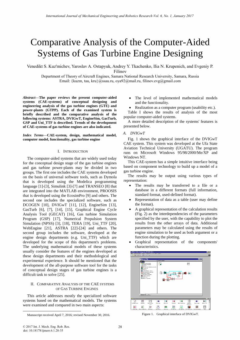
A. DVIGwT
Fig. 1 shows the graphical interface of the DVIGwT CAE system. This system was developed at the Ufa State Aviation Technical University (UGATU). The program runs on Microsoft Windows 95/98/2000/Me/XP and Windows NT.
This CAE-system has a simple intuitive interface being
based on component technology to build up a model of a
gas turbine engine.
The results may be output using various types of
representation:
The results may be transferred to a file or a
database in a different formats (full information,
standard format, used-defined format).
Representation of data as a table (user may define
the format).
A graphical representation of the calculation results
(Fig. 2) as the interdependencies of the parameters
specified by the user, with the capability to plot the
results from the other arrays of data. Additional
parameters may be calculated using the results of
engine simulation to be used as both argument or a
function during the plotting.
Graphical representation of the components'
characteristics.
Figure 1. Graphical interface of DVIGwT.
International Journal of Mechanical Engineering and Robotics Research Vol. 6, No. 1, January 2017
© 2017 Int. J. Mech. Eng. Rob. Res. 28doi: 10.18178/ijmerr.6.1.28-35
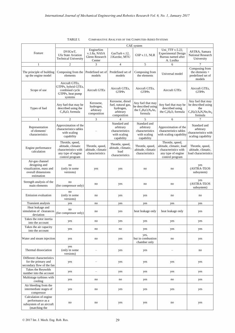
TABLE I. COMPARATIVE ANALYSIS OF THE COMPUTER-AIDED SYSTEMS
Feature
CAE system
DVIGwT, Ufa State Aviation
Technical University
EngineSim v.1.8a, NASA
Glenn Research Center
GasTurb v.12, J.Kurzke, MTU
GSP v.11, NLR
Uni_TTF v.5.22, Experimental Design Bureau named after
A. Lyulka
ASTRA, Samara National Research
University
1 2 3 4 5 6 7
The principle of building up the engine model
Composing from the elements
Predefined set of models
Predefined set of models
Composing from the elements
Universal model
Composing from the elements +
predefined set of models
Scope of use
Aircraft GTEs, GTPPs, hybrid GTEs,
combined cycle GTPPs, heat pump
systems
Aircraft GTEs Aircraft GTEs,
GTPPs Aircraft GTEs,
GTPPs Aircraft GTEs
Aircraft GTEs, GTPPs
Types of fuel Any fuel that may be described using the
CaHbOc formula
Kerosene, hydrogen, arbitrary
composition
Kerosene, diesel fuel, natural gas,
hydrogen, arbitrary
composition
Any fuel that may be described using the CaHbOcNdAre
formula
Any fuel that may be described using
the CaHbOc formula
Any fuel that may be described using
the CaHbOcSdNeNefArg
formula
1 2 3 4 5 6 7
Representation
of elements'
characteristics
Approximation of the
characteristics tables with scaling
capability
–
Standard and arbitrary
characteristics
with scaling capability
Standard and arbitrary
characteristics
with scaling capability
Approximation of the
characteristics tables
with scaling capability
Standard and
arbitrary characteristics with
scaling capability
Engine performance
calculation
Throttle, speed,
altitude, climatic
characteristics with any type of engine
control program
Throttle, speed,
altitude, climatic characteristics
Throttle, speed, altitude, climatic,
load
characteristics
Throttle, speed,
altitude, climatic characteristics
Throttle, speed,
altitude, climatic, load
characteristics with any type of engine
control program
Throttle, speed,
altitude, climatic, load characteristics
Air-gas channel
designing and visualization, mass and
overall dimensions
estimation
no (only in some
versions)
yes yes no no yes
(ASTRA-TEOS
subsystem)
Strength analysis of the
main elements
no
(for compressor only) no yes no no
yes (ASTRA-TEOS
subsystem)
Emission evaluation no
(only in some
versions)
no yes yes no no
Transient analysis yes no yes yes yes yes
Heat leakage and
simulation of clearances deviation
no
(for compressor only) no yes heat leakage only heat leakage only yes
Takes the rotor inertia
into the account yes no yes yes yes yes
Takes the air capacity
into the account yes no no yes yes yes
Water and steam injection yes no yes yes,
but in combustion
chamber only
no yes
Thermal dissociation
yes
(only in some versions)
– yes yes – no
Different characteristics
for the primary and
secondary flow of the fan
yes – yes yes yes yes
Takes the Reynolds number into the account
yes – yes yes yes yes
Multistage turbines with
cooling yes no no yes no yes
Air bleeding from the
intermediate stages of compressor
yes no yes yes yes yes
Calculation of engine
performance as a
subsystem of an aircraft (matching the
no no yes yes no yes
International Journal of Mechanical Engineering and Robotics Research Vol. 6, No. 1, January 2017
© 2017 Int. J. Mech. Eng. Rob. Res. 29

characteristics of engine
with characteristics of
aircraft)
Optimization of the working process
parameters
yes no yes – no (coupled with other
system only) yes
Flight simulation no no yes yes no yes
Multi-objective
optimization of the engine control program
no no no – – yes
Real-time simulation
modeling (virtual testing) no no yes no yes yes
Figure 2. Graphical representation of the results.
DVIGwT system may be used both for solving the
complex engineering problems and during the learning
process of students (currently used at Ufa State Aviation
Technical University).
Figure 3. Graphical interface of EngineSim v.1.8а.
B. EngineSim v.1.8а
This CAE system (Fig. 3) is developed at the NASA
Glenn Research Center. Interactive program is executed as
an applet that makes it cross-platform, but requires a
browser and JavaVirtualMachine runtime environment.
This program may be considered as the most simple
one between the other examined in this article, as it has
the most simple and intuitive interface and the functional
capabilities of EngineSim are also scanty.
There are only two modes of operation:
DesignMode (flight conditions, engine dimensions
and the parameters of engine components may be
changed).
TunnelTestMode (only the flight conditions and
engine throttling may be changed, but the engine
layout remains the same).
Resulting information may be represented in the
following ways:
Graphical output, providing the diagrams of
temperature and pressure corresponding to the
characteristic sections of the engine, the
temperature-entropy and pressure-volume
diagrams.
Output of the engine parameters and its elements'
parameters.
An interesting feature of this program is a warning
message reporting that the temperature in the air-gas
channel of the engine has exceeded the temperature that
the material can withstand. This limit is also displayed on
the chart (Fig. 4).
Figure 4. Plot of stagnation temperature at the characteristic sections of engine.
The program implements a limited set of engines:
single-shaft turbojet, turbojet with afterburner, turbofan
and ramjet. The predefined set of models includes such
engines as J85, F100, CF6 and others.
Thus, EngineSim may be used by beginners, such as
students, to examine the impact of various factors upon
the engine performance.
Figure 5. Graphical interface of GasTurb v.12.
International Journal of Mechanical Engineering and Robotics Research Vol. 6, No. 1, January 2017
© 2017 Int. J. Mech. Eng. Rob. Res. 30

C. GasTurb v.12
This computer-aided system was developed by Joachim
Kurzke (MTU) and runs under the Microsoft Windows
XP with SP2, Vista и Windows 7.
This system has rather intuitive but a bit complex
interface (Fig. 5), so it is more suitable for more
experienced users. The system includes predefined set of
15 models of gas turbine engines and 12 models of gas
turbine power-plants. The use of predefined models makes
the system less universal, but their number and diversity
would be enough for most of the users.
As may be seen from the Table I, the main advantages
of this system are the visual representation of engine air-
gas channel designing (Fig. 6), emission indices
estimation, integrated elements of strength analysis,
engine weight and dimensions estimation, flight
simulation and real-time simulation modeling (virtual
testing). GasTurb also provides the capability to optimize
the working process parameters of the GTE using the
efficiency criteria of aircraft as the higher level system.
These features turn GasTurb into the universal tool for
solving the multilevel and multidisciplinary tasks of the
conceptual design stage of gas turbine engines and power-
plants.
According to the developers, the main advantages of
GasTurb over the similar software are the user-friendly
interface and the quality of graphical output (Fig. 7) [26].
Figure 6. Engine geometry editor.
In addition to the standard elements' characteristics
provides the capability to import the user-defined
characteristics, edit them and scale using a user interface
(Fig. 8). The results and initial data may be transferred to
MS Excel for further processing.
Figure 7. Output in a graphical form.
Figure 8. Compressor characteristic scaling.
GasTurb may be used for both learning process and for
solving the complex engineering problems.
Figure 9. Graphical interface of GSP.
Figure 10. Graphical representation of compressor characteristic.
D. GSP v.11
This computer-aided system was developed at the
National Aerospace Laboratory (NLR). It runs under MS
Windows Vista, Windows 7 and Windows 8.
The system has a simple intuitive interface (Fig. 9). All
modules are divided into categories, so one can quickly
select the one that fits the task to be solved. Each module
contains all the necessary parameters and settings, and this
feature greatly simplifies the work with the system.
According to the developers, the interface of GSP allows
new users to easily perform a "quick start" of analysis
tasks without having to know all of the advanced features.
GSP provides capability to plot the graphical
representation of elements' characteristics (Fig. 10) and to
import the characteristics from a text file.
Capabilities of the graphical user interface of GSP are
somewhat similar to GasTurb: up to four curves may be
put on a single plot (Fig. 11).
International Journal of Mechanical Engineering and Robotics Research Vol. 6, No. 1, January 2017
© 2017 Int. J. Mech. Eng. Rob. Res. 31

Emission indices estimation (using the ICAO tabular
data interpolation, direct prediction simulator or the multi-
reaction simulation) is one of the most important
capabilities of GSP.
The multi-level structure of the computer model
provides capability to include various types of models,
each containing a variety of tasks as the elements
(subsystems) of a top-level model.
Figure 11. Diagram of EINOx, EICO and soot number versus the turbine inlet temperature.
GSP system can be used for both beginners (for
learning needs) and experienced users (for complex
engineering calculations).
E. Uni_TTF v.5.22
This CAE system was developed on the basis of
experimental and methodological experience of
Experimental Design Bureau named after A. Lyulka. The
program runs under various versions of MS operating
system.
This CAE-system has a simple user-friendly interface.
The simplicity of the interface, like the one of EngineSim,
is partially due to the limited set of predefined models of
engines (actually, there is only one universal model of
turbofan) and the limited functional features. The turbofan
is suggested to be the most common type of gas turbine
engine that may be additionally adjusted for various types
of tasks.
Uni_TTF provides the capability to input the user-
defined characteristics of the engine elements using a text
file just like the GasTurb and GSP and the capability to
plot the graphic representation of these characteristics
(Fig. 12).
Figure 12. Graphical representation of compressor characteristic plotted by Uni_TTF.
Displaying the scheme of air bleeding and supply ports
is one of useful features of Uni_TTF (Fig. 13).
Figure 13. Graphical representation of bleeding air flow-paths.
Linkage of the engine model may be complicated for
the beginners, so the adequate theoretical basis of the user
is highly recommended, although the system may be used
for the learning purposes as well as for the engineering
analysis of the aviation turbofans.
F. ASTRA
Developed at Samara State Aerospace University, this
system is cross-platform, but require a Java Virtual
Machine installed to run. The interface of ASTRA is
peculiar, but rather user-friendly (Fig. 14).
Beginners may use the set of 15 predefined engines
models, but an arbitrary model may be composed of the
elements models as well. The models of engines and
elements are grouped in categories (in the similar to GSP
way), providing an easier navigation. New models may be
developed using the models of standard mathematical
operations. Each model or element may be given a user-
defined name.
User may develop complex multi-level models that
may comprise both elements and submodels on each level
with interconnections both at the same level and between
the levels.
Using this feature, such problems like an optimization
of the parameters of a line of gas turbine engines
developed on the basis of a unified engine core (with a
simultaneous optimization of parameters of this engine
core) with a flight simulation for the aircraft efficiency
criteria estimation [30] may be set up and solved.
Figure 14. Graphical interface of ASTRA.
At present, the high efficiency of the modern gas
turbine engines, provided by the high level of working
process parameters, may be further increased by means of
optimization of the engine control program [27, 28].
ASTRA provides the capability to solve this kind of
engineering tasks including the optimization of control
International Journal of Mechanical Engineering and Robotics Research Vol. 6, No. 1, January 2017
© 2017 Int. J. Mech. Eng. Rob. Res. 32

program using the aircraft efficiency criteria, calculated
upon the results of flight simulation [29].
Another feature of ASTRA is a real-time simulation
modeling of the gas turbine engines (Fig. 15) that is
becoming more and more popular nowadays [31].
This method of simulation is a real-time experimental
investigation of a virtual prototype of an engine that is
implemented using a simulator instead of an engine itself
(Fig. 16).
Figure 15. Virtual testing lab of the ASTRA system.
Figure 16. Graphical representation of compressor characteristic with calculated operating points during the transients.
Parallel computing function of the ASTRA may be
useful for solving complex computationally intense tasks,
e.g. functional optimization of the control program with a
nested flight simulation tasks.
III. CONCLUSION
All of the examined CAE systems have roughly the
same core functionality, but various unique features for
solving the specialized engineering tasks. Most systems
may be easily used for both engineering analysis and
during the learning process.
DVIGwT is the most suitable for simulating the gas
turbine engines and power-plants with complex
thermodynamic cycles with heat recovery and
water/steam injection.
The most simple (although having less functionality)
program is EngineSim that is most suitable for students.
GasTurb fits best for solving multi-objective and multi-
disciplinary tasks including weight-dimensions estimation
and emissions evaluation.
GSP implements the most sophisticated models of
emissions evaluation.
Real-time simulation modeling may be performed
using the GasTurb, Uni_TTF and ASTRA.
ASTRA is the only system among the examined that
provide the flight simulation and optimization of the
engine control program.
All the systems examined during this study are poorly
equipped with noise emissions simulators that may be
used during the conceptual design stage of a gas turbine
engine, although influence of noise and emissions
restrictions upon the development of modern aviation
engines has substantially increased lately.
One of the important ways of development of the CAE
systems is a development of interconnected 1- 2- and 3-
dimentional models that are used consequently during the
development of engine in compliance with the amount of
available data.
Another way is the creation of hybrid expert systems of
design and analysis, which will include not only the
mathematical models, but the logical-linguistic models,
representing the accumulated knowledge.
ACKNOWLEDGMENT
This work was supported by the Ministry of education
and science of the Russian Federation in the framework of
the implementation of the Program of increasing the
competitiveness of SSAU among the world's leading
scientific and educational centers for 2013-2020 years.
REFERENCES
[1] J. Shen, K. C. Masiulaniec, and A. A. Afjeh, “Turbojet engine simulation using dymola,” in Proc. Collection of Technical
Papers - AIAA/ASME/SAE/ASEE 42nd Joint Propulsion
Conference, 2006, vol. 6, pp. 4760-4774.
International Journal of Mechanical Engineering and Robotics Research Vol. 6, No. 1, January 2017
© 2017 Int. J. Mech. Eng. Rob. Res. 33
[2] E. T. Samson, “Gas turbine plant modeling for dynamic
simulation,” M.S. thesis. Dept. of Energy Technology, KTH
School of Industrial Engineering and Management, Stockholm,
Sweden, 2011. [3] K. J. Gomes, K. C. Masiulaniec, and A. A. Afjeh, “Performance,
usage, and turbofan transient simulation comparisons between
three commercial simulation tools,” Journal of Aircraft, vol. 46, no. 2, pp. 699-704, 2009.
[4] S. Kim, P. Pilidis, and J. Yin, “Gas turbine dynamic simulation
using simulink,” SAE Technical Paper, 2000-01-3647, 2000. [5] E. Tsoutsanis, N. Meskin, M. Benammar, and K. Khorasani,
“Dynamic performance simulation of an aeroderivative gas
turbine using the matlab simulink environment,” in Proc. International Mechanical Engineering Congress and Exposition,
San Diego, 2013.
[6] C. Kong, H. Roh, and K. Lim, “Steady-state and transient simulation of turboprop engine using simulink model,” in Proc.
ASME Turbo Expo 2003, Atlanta, 2003, pp. 151-161.
[7] C. Kong and H. Roh, “Steady-state performance simulation of PT6A-62 turboprop engine using simulink,” International Journal
of Turbo and Jet Engines, vol. 20, pp. 183-194, 2003.
[8] A. Traverso, “Transeo code for the dynamic performance simulation of micro gas turbine cycles,” in Proc. ASME Turbo
Expo 2005, Reno-Tahoe, 2005, vol. 5, pp. 45-54.
[9] J. Pilet, J.-L. Lecordix, N. Garcia-Rosa, R. Barènes, G. Lavergne, “Towards a fully coupled component zooming approach in engine
performance simulation” in Proc. ASME Turbo Expo 2011,
Vancouver, 2011, vol. 1, pp. 287-299. [10] Electronic Publication. [Online]. Available:
http://www.gecos.polimi.it/software/dcogen.php
[11] M .Gorjunov, “Thermogasdynamic calculations of the gas turbine engines and power-plants using the DVIGwT,” Ufa State
Technical Aviation University Herald, vol. 7, no. 1, pp. 61-70,
2006. [12] I. M. Gorjunov, “System of modeling of power-plant thermal
scheme,” in Proc. International Conference Dedicated to the
Memory of N. D. Kuznetsov, Samara: Samara State Aerospace University, 2001, part 3, pp. 27-31.
[13] Electronic Publication: EngineSimVersion 1.8a. Available: https://www.grc.nasa.gov/WWW/k-12/airplane/ngnsim.html
[14] J. H. Gao and Y. Y. Huang, “Modeling and simulation of an aero
turbojet engine with GasTurb,” in Proc. International Conference on Intelligence Science and Information Engineering, Wuhan,
2011, pp. 295-298.
[15] A. Brandstein, Y. Nakash, Y. Efrati, and D. Perel, “F100PW-229I thermodynamic model simulation with ‘gasTurb 9’,” presented at
the 45th Israel Annual Conference on Aerospace Sciences, 2005.
[16] C. P. DePlachett and R. A. Frederick, “Application of the GECAT software for instruction in gas turbine propulsion analysis,” in
Proc. 36th AIAA/ASME/SAE/ASEE Joint Propulsion Conference
and Exhibit, 2000, pp. 1-9. [17] B. Sankar, T. Subramanian, B. Shah, V. Vanam, et al., “Aero-
thermodynamic modelling and gas path simulation for a twin
spool turbo jet engine,” in Proc. ASME 2013 Gas Turbine India Conference, Bangalore, 2013.
[18] Electronic Publication: What Is Numerical Propulsion System
Simulation (NPSS)? [Online]. Available: http://www.swri.org/npss/pdfs/what-is-npss.pdf
[19] , P. Pilidis, and R. Hales, “TERA- A tool for aero-
engine modelling and management,” presented at the 2nd World Congress on Engineering Asset Management and 4th International
Conference on Condition Monitoring, Harrogate, UK, 11-14 June
2007. [20] I. A. Leshchenko, E. Y. Marchukov, M. Y. Vovkк, and A. A.
Inyukin, “Development and operation of UNI_MM software to
perform thermodynamic calculations of turbofan engines,” in Proc. Scientific-Technical Conference Klimovskie chtenija-2015:
Prospects of Aviation Engines Development, 2015, pp. 33-44.
[21] A. Apostolidis, S. Sampath, P. Laskaridis, and R. Singh, “Webengine: A WEB-based gas turbine performance simulation
tool,” in Proc. ASME Turbo Expo 2013: Turbine Technical
Conference and Exposition, San Antonio, 2013, vol. 4. [22] V. S. Kuz'michev, A. Y. Tkachenko, V. N. Rybakov, I. N.
Krupenich, and V. V. Kulagin, “Methods and means of gas
turbine engines designing using the computer-aided system
ASTRA,” Samara State Aerospace University Herald, vol. 5, no.
36, pp. 160-164, 2012.
[23] A. Y. Tkachenko and V. N. Rybakov, “Transient operation
modeling of a gas turbine engine using the computer-aided system,” in Proc. International Conference Problems and
Prospects of Gas Turbine Engines Development, Samara: Samara
State Aerospace University, 2014, p. 240. [24] V. S. Kuz'michev, V. V. Kulagin, I. N. Krupenich, A. Y.
Tkachenko, and V. N. Rybakov, “Development of the virtual
model of the working process of gas turbine engine using the computer-aided system ASTRA,” Proceedings of the Moscow
Aviation Institute, no. 67, 2013.
[25] S. Carlos, K. Madhavan, G. Gupta, D. Keese, U. Maheshwaraa, and C. C. Seepersad, “Development andapplication of a
flexibility-based method for multi-scale design” in Proc.
Collection of Technical Papers - 11th AIAA/ISSMO Multidisciplinary Analysis and Optimization Conference,
Portsmouth, 2006, vol. 3, pp. 1855-1870.
[26] J. Kurzke. GasTurb 12: Design and Off-Design Performance of Gas Turbines. [Online]. Available: www.gasturb.de
[27] V. S. Kuz'michev, A. Y. Tkachenko, and V. N. Rybakov,
“Aircraft flight simulation during the optimization of the working process parameters of the gas turbine engines,” Proceedings of the
Samara Scientific Center of the Russian Academy of Sciences, vol.
14, no. 1-2, pp. 491-494, 2012. [28] Y. A. Ostapuk and E. P. Filinov, “Optimization of the working
process parameters of the gas turbine engines using the flight
simulation,” in Proc. Scientific-Technical Conference Dedicated to the 100th Anniversary of P.A. Kolesov, Rybinsk: Rybinsk State
Aviation Technological University, 2015, vol. 1, pp. 131-135.
[29] A. Y. Tkachenko and V. S. Kuz'michev, “Dynamic programming method for solving problems of optimization of a gas turbine
engine control program using the criteria of the aircraft,” Samara
State Aerospace University Herald, vol. 5, no. 36, pp. 203-206, 2012.
[30] V. S. Kuz'michev, A. Y. Tkachenko, and V. N. Rybakov,
“Methods of optimization of the working process parameters of the unified engine core and an engine line developed on its basis,”
in Proc. International Conference Problems and Prospects of Gas Turbine Engines Development, Samara: Samara State Aerospace
University, 2014, pp. 238-239.
[31] A. Y. Tkachenko, V. N. Rybakov, Y. A. Ostapuk, and E. P.
Filinov, “Simulation modeling of the working process of gas
turbine engines,” in Proc. International Conference Problems and
Prospects of Gas Turbine Engines Development, Samara: Samara State Aerospace University, 2014, pp. 232-234.
Venedikt S. Kuz'michev is a Doctor of
Science, Professor at Department of Theory of Aircraft Engine, Samara National Research
University, Samara, Russia. His areas of
research: gas turbine engines theory, initial level of gas turbine engine design, assessment
of scientific and technological level of gas
turbine engines, gas turbine engines computer-aided systems.
Yaroslav A. Ostapyuk is a post-graduate
student, Samara National Research University, Samara, Russia. His areas of research: gas
turbine engines theory.
International Journal of Mechanical Engineering and Robotics Research Vol. 6, No. 1, January 2017
© 2017 Int. J. Mech. Eng. Rob. Res. 34
S. O. T. Ogaji
Andrey Y. Tkachenko is a PhD in Technical
Science, Associate professor at Department of
Theory of Aircraft Engine, Samara National
Research University, Samara, Russia. His areas of research: gas turbine engines theory,
mathematical simulation, gas turbine engine
controlling, design methods of field-performance data, numerical method of
optimization.
Ilia N. Krupenich is a PhD in Technical Science, Associate professor at Department of
Theory of Aircraft Engine, Samara National
Research University, Samara, Russia. His areas of research: gas turbine engines theory,
mathematical simulation, gas turbine engine's
turbocompressor design, numbering method of optimization.
Evgeniy P. Filinov is a post-graduate student,
Samara National Research University, Samara,
Russia. His areas of research: gas turbine
engines theory.
International Journal of Mechanical Engineering and Robotics Research Vol. 6, No. 1, January 2017
© 2017 Int. J. Mech. Eng. Rob. Res. 35