Embed Size (px)
Citation preview

Compact NSX Micrologic 5/6/7
DOCA0141EN-00 07/2018
DO
CA0
141E
N-0
0
www.schneider-electric.com
Compact NSX Micrologic 5/6/7Electronic Trip UnitsUser Guide07/2018

The information provided in this documentation contains general descriptions and/or technical character-istics of the performance of the products contained herein. This documentation is not intended as a substitute for and is not to be used for determining suitability or reliability of these products for specific user applications. It is the duty of any such user or integrator to perform the appropriate and complete risk analysis, evaluation and testing of the products with respect to the relevant specific application or use thereof. Neither Schneider Electric nor any of its affiliates or subsidiaries shall be responsible or liable for misuse of the information contained herein. If you have any suggestions for improvements or amendments or have found errors in this publication, please notify us. You agree not to reproduce, other than for your own personal, noncommercial use, all or part of this document on any medium whatsoever without permission of Schneider Electric, given in writing. You also agree not to establish any hypertext links to this document or its content. Schneider Electric does not grant any right or license for the personal and noncommercial use of the document or its content, except for a non-exclusive license to consult it on an "as is" basis, at your own risk. All other rights are reserved.All pertinent state, regional, and local safety regulations must be observed when installing and using this product. For reasons of safety and to help ensure compliance with documented system data, only the manufacturer should perform repairs to components.When devices are used for applications with technical safety requirements, the relevant instructions must be followed. Failure to use Schneider Electric software or approved software with our hardware products may result in injury, harm, or improper operating results.Failure to observe this information can result in injury or equipment damage.© 2018 Schneider Electric. All Rights Reserved.
2 DOCA0141EN-00 07/2018

Table of Contents
Safety Information. . . . . . . . . . . . . . . . . . . . . . . . . . . . . . . . . . . . . . . . . . . . 5About the Book . . . . . . . . . . . . . . . . . . . . . . . . . . . . . . . . . . . . . . . . . . . . . . 7
Chapter 1 Using Micrologic Trip Units . . . . . . . . . . . . . . . . . . . . . . . . . . . . . . . . . . . . . 9Range of Micrologic Trip Units . . . . . . . . . . . . . . . . . . . . . . . . . . . . . . . . . . . . . . . . . . . . . . . 10Description of the Micrologic 5 and 6 Trip Units . . . . . . . . . . . . . . . . . . . . . . . . . . . . . . . . . . 15Description of the Micrologic 7 Trip Unit with Integrated Earth-Leakage Protection . . . . . . . 18Micrologic Trip Unit Power Supply. . . . . . . . . . . . . . . . . . . . . . . . . . . . . . . . . . . . . . . . . . . . . 21Navigation Principles . . . . . . . . . . . . . . . . . . . . . . . . . . . . . . . . . . . . . . . . . . . . . . . . . . . . . . . 24Readout Mode . . . . . . . . . . . . . . . . . . . . . . . . . . . . . . . . . . . . . . . . . . . . . . . . . . . . . . . . . . . . 26Setting Mode . . . . . . . . . . . . . . . . . . . . . . . . . . . . . . . . . . . . . . . . . . . . . . . . . . . . . . . . . . . . . 31Metering Screens . . . . . . . . . . . . . . . . . . . . . . . . . . . . . . . . . . . . . . . . . . . . . . . . . . . . . . . . . 35Protection Function Screens . . . . . . . . . . . . . . . . . . . . . . . . . . . . . . . . . . . . . . . . . . . . . . . . . 37Ecoreach Software . . . . . . . . . . . . . . . . . . . . . . . . . . . . . . . . . . . . . . . . . . . . . . . . . . . . . . . . 45Password Management. . . . . . . . . . . . . . . . . . . . . . . . . . . . . . . . . . . . . . . . . . . . . . . . . . . . . 46
Chapter 2 Protection Function. . . . . . . . . . . . . . . . . . . . . . . . . . . . . . . . . . . . . . . . . . . 472.1 Electrical Distribution Application . . . . . . . . . . . . . . . . . . . . . . . . . . . . . . . . . . . . . . . . . . . . . 48
Electrical Distribution Protection . . . . . . . . . . . . . . . . . . . . . . . . . . . . . . . . . . . . . . . . . . . . . . 49Long-Time Protection . . . . . . . . . . . . . . . . . . . . . . . . . . . . . . . . . . . . . . . . . . . . . . . . . . . . . . 53Short-Time Protection . . . . . . . . . . . . . . . . . . . . . . . . . . . . . . . . . . . . . . . . . . . . . . . . . . . . . . 56Instantaneous Protection. . . . . . . . . . . . . . . . . . . . . . . . . . . . . . . . . . . . . . . . . . . . . . . . . . . . 58Ground-Fault Protection . . . . . . . . . . . . . . . . . . . . . . . . . . . . . . . . . . . . . . . . . . . . . . . . . . . . 59Earth-Leakage Protection . . . . . . . . . . . . . . . . . . . . . . . . . . . . . . . . . . . . . . . . . . . . . . . . . . . 62Neutral Protection . . . . . . . . . . . . . . . . . . . . . . . . . . . . . . . . . . . . . . . . . . . . . . . . . . . . . . . . . 67Zone Selective Interlocking (ZSI) . . . . . . . . . . . . . . . . . . . . . . . . . . . . . . . . . . . . . . . . . . . . . 70Using the ZSI Function with Compact NSX Circuit Breakers . . . . . . . . . . . . . . . . . . . . . . . . 71
2.2 Motor-Feeder Application . . . . . . . . . . . . . . . . . . . . . . . . . . . . . . . . . . . . . . . . . . . . . . . . . . . 73Protection for Motor-Feeders. . . . . . . . . . . . . . . . . . . . . . . . . . . . . . . . . . . . . . . . . . . . . . . . . 74Long-Time Protection . . . . . . . . . . . . . . . . . . . . . . . . . . . . . . . . . . . . . . . . . . . . . . . . . . . . . . 78Short-Time Protection . . . . . . . . . . . . . . . . . . . . . . . . . . . . . . . . . . . . . . . . . . . . . . . . . . . . . . 81Instantaneous Protection. . . . . . . . . . . . . . . . . . . . . . . . . . . . . . . . . . . . . . . . . . . . . . . . . . . . 82Ground-Fault Protection . . . . . . . . . . . . . . . . . . . . . . . . . . . . . . . . . . . . . . . . . . . . . . . . . . . . 83Phase Unbalance Protection . . . . . . . . . . . . . . . . . . . . . . . . . . . . . . . . . . . . . . . . . . . . . . . . . 86Motor Jam Protection . . . . . . . . . . . . . . . . . . . . . . . . . . . . . . . . . . . . . . . . . . . . . . . . . . . . . . 88Underload Motor Protection. . . . . . . . . . . . . . . . . . . . . . . . . . . . . . . . . . . . . . . . . . . . . . . . . . 90Long-Start Motor Protection . . . . . . . . . . . . . . . . . . . . . . . . . . . . . . . . . . . . . . . . . . . . . . . . . 91
Chapter 3 Metering Function . . . . . . . . . . . . . . . . . . . . . . . . . . . . . . . . . . . . . . . . . . . . 933.1 Measurement Techniques . . . . . . . . . . . . . . . . . . . . . . . . . . . . . . . . . . . . . . . . . . . . . . . . . . . 94
Real-Time Measurements . . . . . . . . . . . . . . . . . . . . . . . . . . . . . . . . . . . . . . . . . . . . . . . . . . . 95Calculating Demand Values (Micrologic E) . . . . . . . . . . . . . . . . . . . . . . . . . . . . . . . . . . . . . . 99Power Metering (Micrologic E) . . . . . . . . . . . . . . . . . . . . . . . . . . . . . . . . . . . . . . . . . . . . . . . 101Power Calculation Algorithm . . . . . . . . . . . . . . . . . . . . . . . . . . . . . . . . . . . . . . . . . . . . . . . . . 104Energy Metering (Micrologic E) . . . . . . . . . . . . . . . . . . . . . . . . . . . . . . . . . . . . . . . . . . . . . . . 106Harmonic Currents . . . . . . . . . . . . . . . . . . . . . . . . . . . . . . . . . . . . . . . . . . . . . . . . . . . . . . . . 108Metering Energy Quality Indicators (Micrologic E) . . . . . . . . . . . . . . . . . . . . . . . . . . . . . . . . 110Power Factor PF and cos ϕ Measurement (Micrologic E). . . . . . . . . . . . . . . . . . . . . . . . . . . 112
3.2 Measurement Accuracy Tables . . . . . . . . . . . . . . . . . . . . . . . . . . . . . . . . . . . . . . . . . . . . . . . 116Measurement Accuracy. . . . . . . . . . . . . . . . . . . . . . . . . . . . . . . . . . . . . . . . . . . . . . . . . . . . . 117Micrologic A - Real-Time Measurements . . . . . . . . . . . . . . . . . . . . . . . . . . . . . . . . . . . . . . . 118Micrologic E - Real-Time Measurements . . . . . . . . . . . . . . . . . . . . . . . . . . . . . . . . . . . . . . . 119Micrologic E - Demand Value Measurements . . . . . . . . . . . . . . . . . . . . . . . . . . . . . . . . . . . . 124Micrologic E - Energy Metering . . . . . . . . . . . . . . . . . . . . . . . . . . . . . . . . . . . . . . . . . . . . . . . 125
DOCA0141EN-00 07/2018 3

Chapter 4 Alarms . . . . . . . . . . . . . . . . . . . . . . . . . . . . . . . . . . . . . . . . . . . . . . . . . . . . . 127Alarms Associated with Measurements . . . . . . . . . . . . . . . . . . . . . . . . . . . . . . . . . . . . . . . . . 128Alarms on a Trip, Failure, and Maintenance Event . . . . . . . . . . . . . . . . . . . . . . . . . . . . . . . . 131Tables of Alarms . . . . . . . . . . . . . . . . . . . . . . . . . . . . . . . . . . . . . . . . . . . . . . . . . . . . . . . . . . 132Operation of SDx and SDTAM Module Outputs Assigned to Alarms. . . . . . . . . . . . . . . . . . . 136
Chapter 5 Operating Assistance . . . . . . . . . . . . . . . . . . . . . . . . . . . . . . . . . . . . . . . . . . 139LED Indication . . . . . . . . . . . . . . . . . . . . . . . . . . . . . . . . . . . . . . . . . . . . . . . . . . . . . . . . . . . . 140Indication on the Micrologic Display. . . . . . . . . . . . . . . . . . . . . . . . . . . . . . . . . . . . . . . . . . . . 142Examples of Using Alarms . . . . . . . . . . . . . . . . . . . . . . . . . . . . . . . . . . . . . . . . . . . . . . . . . . . 148Alarm Monitoring of the cos ϕ and Power Factor. . . . . . . . . . . . . . . . . . . . . . . . . . . . . . . . . . 149Circuit Breaker Communication . . . . . . . . . . . . . . . . . . . . . . . . . . . . . . . . . . . . . . . . . . . . . . . 151History and Time-Stamped Information . . . . . . . . . . . . . . . . . . . . . . . . . . . . . . . . . . . . . . . . . 152Maintenance Indicators . . . . . . . . . . . . . . . . . . . . . . . . . . . . . . . . . . . . . . . . . . . . . . . . . . . . . 153
Appendices . . . . . . . . . . . . . . . . . . . . . . . . . . . . . . . . . . . . . . . . . . . . . . . . . . . . . . 155Appendix A Additional Characteristics . . . . . . . . . . . . . . . . . . . . . . . . . . . . . . . . . . . . . . . 157
Compact NSX100-250 - Distribution Protection. . . . . . . . . . . . . . . . . . . . . . . . . . . . . . . . . . . 158Compact NSX100-250 - Motor-Feeder Protection . . . . . . . . . . . . . . . . . . . . . . . . . . . . . . . . . 159Compact NSX400-630 - Distribution Protection. . . . . . . . . . . . . . . . . . . . . . . . . . . . . . . . . . . 160Compact NSX400-630 - Motor-Feeder Protection . . . . . . . . . . . . . . . . . . . . . . . . . . . . . . . . . 161Compact NSX100-630 - Reflex Tripping . . . . . . . . . . . . . . . . . . . . . . . . . . . . . . . . . . . . . . . . 162Compact NSX100-630 - Limitation Curves . . . . . . . . . . . . . . . . . . . . . . . . . . . . . . . . . . . . . . 163
4 DOCA0141EN-00 07/2018

Safety Information
Important Information
NOTICERead these instructions carefully, and look at the equipment to become familiar with the device before trying to install, operate, service, or maintain it. The following special messages may appear throughout this documentation or on the equipment to warn of potential hazards or to call attention to information that clarifies or simplifies a procedure.
PLEASE NOTEElectrical equipment should be installed, operated, serviced, and maintained only by qualified personnel. No responsibility is assumed by Schneider Electric for any consequences arising out of the use of this material.A qualified person is one who has skills and knowledge related to the construction and operation of electrical equipment and its installation, and has received safety training to recognize and avoid the hazards involved.
DOCA0141EN-00 07/2018 5

6 DOCA0141EN-00 07/2018

About the Book
At a Glance
Document ScopeThe aim of this guide is to provide users, installers, and maintenance personnel with the technical information needed to operate the Micrologic™ trip units in Compact™ NSX circuit breakers.
Validity NoteThis guide is applicable to the trip units: Micrologic 5.2 A, 5.3 A, 5.2 E, and 5.3 E Micrologic 6.2 A, 6.3 A, 6.2 E, and 6.3 E Micrologic 6.2 E-M and 6.3 E-M Micrologic 7.2 E and 7.3 E with integrated earth-leakage Micrologic 7.2 E-AL and 7.3 E-AL with integrated earth-leakageFor information on the other trip units in the Micrologic range and the thermal-magnetic trip units on Compact NSX circuit breakers, refer to Compact NSX - Circuit Breakers and Switch-Disconnectors 100–630 A - User Guide.The information contained in this guide is likely to be updated at any time. Schneider Electric strongly recommends that you have the most recent and up-to-date version available on www.schneider-electric.com.The technical characteristics of the devices described in the present document also appear online. To access the information online:
The characteristics that are presented in the present manual should be the same as those characteristics that appear online. In line with our policy of constant improvement, we may revise content over time to improve clarity and accuracy. If you see a difference between the manual and online information, use the online information as your reference.
Step Action1 Go to the Schneider Electric home page www.schneider-electric.com.2 In the Search box type the reference of a product or the name of a product range.
Do not include blank spaces in the reference or product range. To get information on grouping similar modules, use asterisks (*).
3 If you entered a reference, go to the Product Datasheets search results and click on the reference that interests you.If you entered the name of a product range, go to the Product Ranges search results and click on the product range that interests you.
4 If more than one reference appears in the Products search results, click on the reference that interests you.
5 Depending on the size of your screen, you may need to scroll down to see the data sheet.6 To save or print a data sheet as a .pdf file, click Download XXX product datasheet.
DOCA0141EN-00 07/2018 7

Related Documents
You can download these technical publications and other technical information from our website at https://www.schneider-electric.com/en/download
Trademark NoticeAll trademarks are owned by Schneider Electric Industries SAS or its affiliated companies.
Title of Documentation Reference NumberCompact NSX & NSXm Catalogue LVPED217032ENCompact NSX - Circuit Breakers and Switch-Disconnectors 100–630 A - User Guide DOCA0140EN
DOCA0140ESDOCA0140FRDOCA0140ZH
Compact NSX - Modbus Communication Guide DOCA0091ENDOCA0091ESDOCA0091FRDOCA0091ZH
Enerlin'X IO - Input/Output Application Module for One IEC Circuit Breaker - User Guide DOCA0055ENDOCA0055ESDOCA0055FRDOCA0055ZH
Enerlin'X IFE - Ethernet Interface for One IEC Circuit Breaker - User Guide DOCA0142ENDOCA0142ESDOCA0142FRDOCA0142ZH
Enerlin'X IFE - Ethernet Switchboard Server - User Guide DOCA0084ENDOCA0084ESDOCA0084FRDOCA0084ZH
ULP System (IEC Standard) - User Guide DOCA0093ENDOCA0093ESDOCA0093FRDOCA0093ZH
Enerlin’X FDM121 - Front Display Module for One Circuit Breaker - User Guide DOCA0088ENDOCA0088ESDOCA0088FRDOCA0088ZH
8 DOCA0141EN-00 07/2018

Compact NSX Micrologic 5/6/7Using Micrologic Trip UnitsDOCA0141EN-00 07/2018
Using Micrologic Trip Units
Chapter 1Using Micrologic Trip Units
What Is in This Chapter?This chapter contains the following topics:
Topic PageRange of Micrologic Trip Units 10Description of the Micrologic 5 and 6 Trip Units 15Description of the Micrologic 7 Trip Unit with Integrated Earth-Leakage Protection 18Micrologic Trip Unit Power Supply 21Navigation Principles 24Readout Mode 26Setting Mode 31Metering Screens 35Protection Function Screens 37Ecoreach Software 45Password Management 46
DOCA0141EN-00 07/2018 9

Using Micrologic Trip Units
Range of Micrologic Trip Units
PresentationMicrologic trip units are used on the Compact NSX circuit breakers. The range of Micrologic trip units consists of several families of electronic trip unit: Micrologic 1, 2, trip units and Micrologic Vigi 4 trip units without display Micrologic 5, 6, trip units and Micrologic Vigi 7 trip units with display
A TM-D, TM-G, or MA trip unitB Micrologic 1 or 2 trip unitC Micrologic 5 or 6 trip unitD Vigi module for additional
earth-leakage protectionE Micrologic 4 trip unit with
integrated earth-leakage protection
F Micrologic 7 trip unit with integrated earth-leakage protection
10 DOCA0141EN-00 07/2018
Using Micrologic Trip Units
Description of the Micrologic 1, 2, and Vigi 4 Trip UnitsMicrologic trip units are grouped by application. A distinction is made between electrical power distribution applications and motor protection applications: In the electrical power distribution application: Micrologic 2.2 and 2.3 trip units are designed to protect conductors in commercial and industrial
electrical distribution. Micrologic 4.2 and 4.3 trip units with integrated earth-leakage protection are designed to protect
electrical conductors, goods, and people in commercial and industrial electrical distribution (Micrologic 4.2 AL and 4.3 AL trip units with integrated earth-leakage protection are designed to measure earth-leakage current).
In the motor protection application: Micrologic 1.3 M trip units are adapted to short-circuit protection of motor-feeders. Micrologic 2.2 M and 2.3 M trip units are adapted to protecting motor-feeders on standard
applications. The thermal tripping curves are calculated for self-cooled motors.The adjustment dials and indications are on the front face.For more information about Micrologic 1, 2, and 4 trip units, refer to Compact NSX - Circuit Breakers and Switch-Disconnectors 100–630 A - User Guide (see page 8).
Description of the Micrologic 5, 6, and Vigi 7 Trip UnitsMicrologic 5, 6, and Vigi 7 trip units are available for electrical power distribution applications and motor protection applications: In the electrical power distribution application, Micrologic 5.2, 5.3, 6.2, 6.3, Vigi 7.2, and Vigi 7.3 trip
units are designed to protect conductors, goods, and people in commercial and industrial electrical distribution.
In the motor protection application, Micrologic 6.2 M and 6.3 M are adapted to protecting motor-feeders on standard applications. The thermal tripping curves are calculated for self-cooled motors.
Micrologic 5, 6, and Vigi 7 trip units provide: Adjustable tripping functions on electronic trip circuit breakers Protection for the electrical distribution system or specific applications Metering of instantaneous and demand values Kilowatt-hour metering Operating information (such as peak demand values, customized alarms, operation counters) CommunicationMicrologic trip units can be configured to communicate with other devices. For information on the maintenance and communication modules, refer to the following documents (see page 8): Compact NSX & NSXm Catalogue Compact NSX - Circuit Breakers and Switch-Disconnectors 100–630 A - User GuideFor complete information on available circuit breaker models, frame sizes, interrupting ratings, and trip units, refer to Compact NSX & NSXm Catalogue
DOCA0141EN-00 07/2018 11

Using Micrologic Trip Units
Identification The product name specifies the protection provided by the trip unit.
Identification on Micrologic electronic trip units
In RatingThe trip unit In value is visible on the front face of the circuit breaker when the trip unit is installed. The trip unit In rating (in amperes) is the maximum value of the trip unit.
Example: Micrologic 5.2 A 250 A trip unit: Setting range: 100–250 A In rating = 250 A
Examples Type of protection (X)
Case (Y) Type of measurement (Z)
Application (T)
–
1 SI2 LS0I4 LS0IR5 LSI6 LSIG7 LSIR
2 Compact NSX 100/160/250
3 Compact NSX 400/630
A AmmeterE Energy
DistributionG GeneratorAB SubscriberM MotorZ 16 Hz 2/3AL Alarm without trip
for earth-leakage protection
Micrologic 1.3 M SI 400 or 630 A – MotorMicrologic 2.2 G LS0I 100, 160 or 250 A – Generator
Micrologic 2.3 LS0I 400 or 630 A – Distribution
Micrologic 2.3 M LS0I 400 or 630 A – Motor
Micrologic Vigi 4.2 LS0IR 100, 160 or 250 A – Distribution including trip on earth-leakage
Micrologic Vigi 4.3 AL LS0I 400 or 570 A – Distribution including alarm on earth-leakage
Micrologic 5.2 A LSI 100, 160 or 250 A Ammeter DistributionMicrologic 5.3 E LSI 400 or 630 A Energy DistributionMicrologic 6.3 E-M LSIG 400 or 630 A Energy MotorMicrologic Vigi 7.2 E-AL LSI 100, 160 or 250 A Energy Distribution including
alarm on earth-leakageMicrologic Vigi 7.3 E LSIR 400 or 600 A Energy Distribution including
trip on earth-leakageType of protection:I InstantaneousL Long-timeS0 Short-time (time delay cannot be adjusted)S Short-timeG Ground-faultR Earth-leakage (residual)
12 DOCA0141EN-00 07/2018

Using Micrologic Trip Units
Integrating Micrologic Trip Units on the Compact NSX Range of Circuit BreakersMicrologic trip units for electrical distribution can be used on any Compact NSX circuit breaker.The following table indicates configurations available according to the In rating of the distribution trip unit and the circuit breaker size:
Micrologic 2 M or 6 E-M trip units can be used on any Compact NSX circuit breaker.The following table indicates configurations available according to the In rating of the motor trip unit and the circuit breaker size:
Micrologic 1.3 M trip units can be used on Compact NSX400 and Compact NSX630 circuit breakers.The following table indicates configurations available according to the In rating of the motor trip unit and the circuit breaker size:
Interchangeability of Micrologic Trip UnitsOnsite replacement of trip units is simple: No connections to make No special tools (for example, calibrated torque wrench) Compatibility of trip units provided by mechanical cap Torque limited screw provides correct torque (see drawing below)
The simplicity of the replacement process means that it is easy to make the necessary adjustments as operation and maintenance processes evolve.NOTE: The screw head is accessible when the trip unit is installed, so the trip unit can still be removed.NOTE: On the Compact NSX circuit breaker with R, HB1, and HB2 breaking performances the trip units are not interchangeable.
Micrologic In rating 40 100 160 250 400 630Compact NSX100 ✓ ✓ – – – –Compact NSX160 ✓ ✓ ✓ – – –Compact NSX250 ✓ ✓ ✓ ✓ – –Compact NSX400 – – – ✓ (1) ✓ –
Compact NSX630 – – – ✓ (1) ✓ ✓
(1) Micrologic 2.3 only
Micrologic M In rating 25 50 80 100 150 220 320 500Compact NSX100 ✓ ✓ ✓ (1) ✓ (2) – – – –
Compact NSX160 ✓ ✓ ✓ (1) ✓ (2) ✓ – – –
Compact NSX250 ✓ ✓ ✓ (1) ✓ (2) ✓ ✓ – –
Compact NSX400 – – – – – – ✓ –Compact NSX630 – – – – – – ✓ ✓(1) Micrologic 6 E-M only(2) Micrologic 2 M only
Micrologic 1.3 M In rating
320 500
Compact NSX400 ✓ –Compact NSX630 ✓ ✓
DOCA0141EN-00 07/2018 13

Using Micrologic Trip Units
Sealing the ProtectionSeal the transparent cover on Micrologic trip units to prevent modification of protection settings and to prevent access to the test port.On Micrologic 5, 6, and Vigi 7 trip units, the keypad can be used and the protection settings and measurements can be read on the screen with the cover sealed.
14 DOCA0141EN-00 07/2018

Using Micrologic Trip Units
Description of the Micrologic 5 and 6 Trip Units
Trip Unit Front FaceUse the display screen and keypad on the trip unit to set the trip unit options and check system measurements. Refer to the navigation principles for more information (see page 24).Front face of a Micrologic 5.2 A trip unit for a 3-pole circuit breaker
A Indication LEDsB Test portC Dials for presetting protection functions and microswitch for locking protection settingD LCD displayE Navigation keypad
Indication LEDsIndication LEDs show the trip unit operational state.Indication LEDs vary in meaning depending on the trip unit type.
Test PortMicrologic trip units feature a test port specifically for maintenance actions.Use the test port to: Connect a pocket battery for local testing of the Micrologic trip unit Connect the USB maintenance interface for testing, setting the Micrologic trip unit, and for installation
diagnosticsFor more information, refer to Compact NSX - Circuit Breakers and Switch-Disconnectors 100–630 A - User Guide (see page 8).
Type of Micrologic trip unit DescriptionDistribution Ready LED (green) blinks slowly when the standard protection functions of the
electronic trip unit are operational. Overload pre-alarm LED (orange) lights when the load exceeds 90% of the Ir
setting. Overload alarm LED (red) lights when the load exceeds 105% of the Ir setting.
Motor Ready LED (green) blinks slowly when the standard protection functions of the electronic trip unit are operational.
Overload temperature alarm LED (red) lights when the motor thermal image exceeds 95% of the Ir setting.
DOCA0141EN-00 07/2018 15

Using Micrologic Trip Units
Dials and MicroswitchThe trip unit face has two dials for presetting protection functions and a microswitch for locking/unlocking the protection settings done with the keypad. For distribution trip units, the dials are for setting long-time and instantaneous protection.
LCD DisplayAn LCD display provides information necessary to use the trip unit. The list of protection functions varies according to the Micrologic trip unit type.
A Long-time protection pickup (Ir) adjustment dialB Short-time protection pickup (Isd) adjustment dial
(Micrologic 5 only)C Ground-fault protection pickup (Ig) adjustment dial
(Micrologic 6 only)D Microswitch for locking/unlocking the protection
parameter settings
Item DescriptionA 5 pictograms:
: Metering : Readout : Protection : Setting : LockThe combination of pictograms defines the mode.
B Up arrow points to protection function currently being setC List of protection functions according to the Micrologic trip unit type:
Micrologic 5:
Micrologic 6:
Micrologic 6 E-M:
D Value of the measured quantityE Unit of the measured quantityF Navigation arrowsG Down arrows point to the selected phase(s), neutral, or groundH Phases (1/A, 2/B, 3/C), neutral (N) and ground
16 DOCA0141EN-00 07/2018

Using Micrologic Trip Units
LCD Display BacklightingWhen the Micrologic trip unit is powered by an external 24 Vdc power supply, the trip unit display has white backlighting that is: Low intensity continuously High intensity for 1 minute after pressing one of the keys on the keypadThe display backlighting is: Deactivated if the temperature exceeds 65 °C (149 °F). Reactivated once the temperature drops back below 60 °C (140 °F).On trip units powered by the pocket battery, the display unit is not backlit.
Navigation KeypadUse the 5-key keypad for navigation.
Key DescriptionSelecting the mode
Scrolling navigation
Navigation back (metering) or - (setting the protection functions)
Navigation forward (metering) or + (setting the protection functions)
Confirmation
DOCA0141EN-00 07/2018 17

Using Micrologic Trip Units
Description of the Micrologic 7 Trip Unit with Integrated Earth-Leakage Protection
PresentationThe Micrologic Vigi 7 electronic trip unit is available in two versions for earth-leakage detection: The Trip version trips when earth-leakage is detected. The Alarm version measures the earth-leakage current and indicates an earth-leakage fault on the
display screen.When the SDx indication contact is present, it signals an earth-leakage fault remotely.
Trip Unit Front FaceUse the display screen and keypad on the trip unit to set the trip unit options and check system measurements. Refer to the navigation principles for more information (see page 24).Front face of a Micrologic Vigi 7 trip unit (Trip version):
A Indication LEDsB Adjustment dials for presetting protection functions, microswitch for locking protection setting, and test button for
testing earth-leakage protectionC LCD display screenD Navigation keypadE Test portF Dielectric switch
Indication LEDsIndication LEDs show the trip unit operational state.
A Ready LED (green) blinks slowly when the standard protection functions of the electronic trip unit are operational.B Overload pre-alarm LED (orange) lights when the load exceeds 90% of the Ir setting.C Overload alarm LED (red) lights when the load exceeds 105% of the Ir setting.
Dials, Microswitch, and Test ButtonThe trip unit face has two adjustment dials for presetting protection functions, a microswitch for locking/unlocking the protection settings, and a test button for testing the earth-leakage protection.
A Long-time protection pickup (Ir) adjustment dialB Earth-leakage protection pickup (IΔn) adjustment dialC Test button for testing earth-leakage protectionD Microswitch to lock/unlock the protection settings
18 DOCA0141EN-00 07/2018

Using Micrologic Trip Units
LCD DisplayAn LCD display provides information necessary to use the trip unit. The list of protection functions varies according to the Micrologic trip unit type.
LCD Display BacklightingWhen the Micrologic trip unit is powered by an external 24 Vdc power supply, the trip unit display has white backlighting that is: Low intensity continuously High intensity for 1 minute after pressing one of the keys on the keypadThe display backlighting is: Deactivated if the temperature exceeds 65 °C (149 °F). Reactivated once the temperature drops back below 60 °C (140 °F).On trip units powered by the pocket battery, the display unit is not backlit.
Navigation KeypadUse the 5-key keypad for navigation.
Test PortMicrologic trip units feature a test port specifically for maintenance actions.Use the test port to: Connect a pocket battery for local testing of the Micrologic trip unit Connect the USB maintenance interface for testing, setting the Micrologic trip unit and for installation
diagnosticsFor more information, refer to Compact NSX - Circuit Breakers and Switch-Disconnectors 100–630 A - User Guide (see page 8).
Item DescriptionA 5 pictograms:
: Metering : Readout : Protection : Setting : LockThe combination of pictograms defines the mode.
B Up arrow points to protection function currently being setC List of protection functions for Micrologic Vigi 7 trip unit:
D Value of the measured quantityE Unit of the measured quantityF Navigation arrowsG Down arrows point to the selected phase(s), neutral, or the groundH Phases (1/A, 2/B, 3/C), neutral (N) and ground
Key DescriptionSelecting the mode
Scrolling navigation
Navigation back (metering) or - (setting the protection functions)
Navigation forward (metering) or + (setting the protection functions)
Confirmation
DOCA0141EN-00 07/2018 19

Using Micrologic Trip Units
Dielectric SwitchThe dielectric switch disconnects the trip unit power supply from the phases. It is used when performing a panel dielectric test.For more information about how to use the dielectric switch, refer to Compact NSX - Circuit Breakers and Switch-Disconnectors 100–630 A - User Guide (see page 8).
20 DOCA0141EN-00 07/2018

Using Micrologic Trip Units
Micrologic Trip Unit Power Supply
Internal Power Supply for Micrologic 5 and 6 Trip UnitsThe protection functions and the test functions of Micrologic 5 and 6 trip units operate with the current through the internal current transformers (CT).When the load current is higher than 20% of the rated current In, the internal current supply provides the power supply for the full functioning of the Micrologic trip unit. This includes: The Micrologic display screen and LEDs The maintenance and diagnostic functionsTo provide a power supply to the Micrologic 5 or 6 trip unit when the load is below 20% of the rated current In, and maintain the full functioning of the Micrologic trip unit, one of the following optional power supplies can be used: An external 24 Vdc power supply connected permanently to the Micrologic trip unit A power supply connected temporarily to the test port on the Micrologic trip unit: Pocket battery PC through USB maintenance interface
Each optional Micrologic power supply is described further.
Internal Power Supply for Micrologic 7 Trip Units with Integrated Earth-Leakage ProtectionThe protection functions and the test functions of Micrologic Vigi 7 trip units operate with the current through the internal current transformers (CT) and the internal voltage power supply. The Micrologic display screen, LEDs, and maintenance and protection functions are available whatever the load current.
External 24 Vdc Power SupplyThe 24 Vdc power supply maintains the operation of the functions of the Micrologic trip unit in all circumstances, including in low load conditions (load below 20%), and when the circuit breaker is open and not energized. The 24 Vdc power supply is essential to enable the Micrologic trip unit to display the trip cause.The external 24 Vdc power supply is provided to the Micrologic trip unit once it is connected to another module in the ULP system (for example, IFM Modbus-SL interface for one circuit breaker).When the Micrologic trip unit is not connected to a ULP module, it can be connected directly to an external 24 Vdc power supply by using the optional 24 Vdc supply terminal block.One 24 Vdc power supply can be used to provide power to several Micrologic trip units or other ULP modules.
DOCA0141EN-00 07/2018 21

Using Micrologic Trip Units
Recommended 24 Vdc Power SuppliesAvailable 24 Vdc power supplies include the range of the Phaseo ABL8 power supplies and the AD power supplies. For more information, refer to Compact NSX & NSXm Catalogue (see page 8).
NOTE: For applications requiring an overvoltage category higher than II, install a surge arrester when using a 24 Vdc ABL8 power supply.
Characteristic Phaseo ABL8 power supply AD power supplyIllustration
Overvoltage category defined byIEC/EN 60947-1
Category II Category IV
Input supply voltage AC
110–120 Vac 200–500 Vac
110–130 Vac 200–240 Vac 380–415 Vac
Input supply voltage DC
– 24–30 Vdc 48–60 Vdc 100–125 Vdc
Dielectric withstand Input/output: 4 kV RMS for 1 minute Input/ground: 3 kV RMS for 1 minute Output/ground: 0.5 kV RMS for 1 minute
Input/output: 3.5 kV RMS for 1 minute (380 Vac model) 3 kV RMS for 1 minute (110–130 Vac and
200–240 Vac model) 3 kV RMS for 1 minute (110–125 Vdc
model) 2 kV RMS for 1 minute (24–30 Vdc and
48–60 Vdc model)Temperature 50 °C (122 °F)
60 °C (140 °F) with 80% nominal load maximum
70 °C (158 °F)
Output current 3 A or 5 A 1 ARipple 200 mV peak-peak 240 mV peak-peakOutput voltage setting for line loss compensation
24–28.8 Vdc –
22 DOCA0141EN-00 07/2018

Using Micrologic Trip Units
ULP Module ConsumptionThe following table lists the ULP module consumption:
For more information on power supplies, refer to ULP System (IEC Standard) - User Guide (see page 8).
Pocket Battery
Check the charge level of the pocket battery by sliding the switch to the Test position. The green LED on the pocket battery lights up to indicate the battery status.For more information on the pocket battery, refer to Compact NSX - Circuit Breakers and Switch-Disconnectors 100–630 A - User Guide (see page 8).
USB Maintenance InterfaceDuring periods of setting, commissioning, testing, and maintenance, the USB maintenance interface, connected to the test port on the Micrologic trip unit provides a temporary power supply.For more information on the USB maintenance interface, refer to Compact NSX - Circuit Breakers and Switch-Disconnectors 100–630 A - User Guide (see page 8).
Module Typical consumption (24 Vdc at 20 °C/68 °F)
Maximum consumption (19.2 Vdc at 60 °C/140 °F)
Micrologic trip unit for Compact NSX circuit breaker 30 mA 55 mABSCM circuit breaker status control module for Compact NSX circuit breakers
9 mA 15 mA
IFE Ethernet switchboard server 100 mA 140 mAIFE Ethernet interface for one circuit breaker 100 mA 140 mAIFM Modbus-SL interface for one circuit breaker 21 mA 30 mAIO input/output application module for one circuit breaker 100 mA 130 mAFDM121 front display module for one circuit breaker 21 mA 30 mAUSB maintenance interface 0 mA (the USB
maintenance interface has its own power supply)
0 mA (the USB maintenance interface has its own power supply)
The pocket battery is an external battery that enables power to be supplied temporarily to the Micrologic trip unit.The pocket battery enables use of the Micrologic display screen and keypad for setting and displaying when the power supply to the Micrologic trip unit is interrupted.The pocket battery can be connected by using the trip unit connector (supplied with the pocket battery) connected to the test port on the Micrologic trip unit.
DOCA0141EN-00 07/2018 23

Using Micrologic Trip Units
Navigation Principles
Lock/Unlock the SettingsThe protection settings are locked when the transparent cover is closed and sealed to prevent access to the adjustment dials and the locking/unlocking microswitch.A pictogram on the display indicates whether the protection settings are locked: Padlock locked : The protection settings are locked.
Padlock unlocked : The protection settings are unlocked.To unlock the protection settings:1. Open the transparent cover2. Press the lock/unlock microswitch or turn one of the adjustment dialsTo lock the protection settings, press the lock/unlock microswitch again.The protection settings also lock automatically five minutes after pressing a key on the keypad or turning one of the dials on the Micrologic trip unit.
Trip Unit ModesInformation displays on the Micrologic trip unit are based on its mode.The modes available depend on: Whether the settings are locked The trip unit version (3-pole or 4-pole)The combination of pictograms defines the mode.The following tables show the possible modes:
Mode Selection
Select mode by successive presses on the key: The modes scroll cyclically. Press the lock/unlock microswitch to switch between readout mode and setting mode.
Pictograms Mode accessible with padlock locked Instantaneous measurement readout Kilowatt hour meter readout and reset
Peak demand readout and reset
Protection function readout
Neutral status readout (3-pole Micrologic trip unit)
PictogramsMode accessible with padlock unlocked Instantaneous measurement readout Kilowatt hour meter readout and reset
Peak demand readout and reset
Protection function setting
Neutral status setting (3-pole Micrologic trip unit)
24 DOCA0141EN-00 07/2018

Using Micrologic Trip Units
ScreensaverThe screensaver displays the instantaneous current passing through the most heavily loaded phase (Instantaneous measurement readout mode).The Micrologic display automatically reverts to a screensaver: In padlock locked mode, 20 seconds after the last action on the keypad In padlock unlocked mode, 5 minutes after the last action on the keypad or dials
DOCA0141EN-00 07/2018 25

Using Micrologic Trip Units
Readout Mode
Measurement ReadoutMicrologic 5 and 6 trip units and Micrologic 7 trip units with integrated earth-leakage protection have the same five navigation keys. The appearance of the keys differs, as shown in the following table:
The following examples use the keys of the Micrologic 5 and 6 trip units to illustrate navigation for readout and setting modes. For Micrologic Vigi 7 trip units, navigation is made in the same way.
A measurement is read using the and keys. The keys are used to select the measurement to be displayed on-screen. The associated
navigation arrows indicate the navigation options:
: possible to press the key
: possible to press the key
: possible to press either of the two keys
For the current and voltage measured quantities, the navigation key can be used to select the metering screen for each of the phases: The down arrow indicates the phase relating to the measurement value displayed.
Examples:Quantity measured on phase 2
Quantity measured on all 3 phases
Press the key successively to scroll through the metering screens. Scrolling is cyclical.
Micrologic 5 and 6 trip unit Micrologic Vigi 7 trip unit
26 DOCA0141EN-00 07/2018

Using Micrologic Trip Units
Example of Measurement Readout (Micrologic E)The following table gives the readout values of the 3 phase currents, the phase-to-phase voltage V12, the total active power (Ptot), and the earth-leakage current (IΔn):
Energy Meter Readout (Micrologic E)Energy meters change measurement unit automatically: For active energy, Ep, displayed in kWh from 0 to 9999 kWh then in MWh For reactive energy, Eq, displayed in kVARh from 0 to 9999 kVARh then in MVARh For apparent energy, Es, displayed in kVAh from 0 to 9999 kVAh then in MVAhWhen energies are indicated in MWh, MkVARh, or MVAh, the values display on 4 digits. The Micrologic trip unit incorporates the option of full energy meter readout. NOTE: The energy meter can be reset with the padlock locked or unlocked.
Step Action Using Display1 Select the Instantaneous
measurement readout mode (the most heavily loaded phase is displayed).Read the value of current I2.
2 Select the next current measurement: current I3.Read the value of current I3.
3 Select the next current measurement: current I1.Read the value of current I1.
4 Select the phase-to-phase voltage V12 measurement.Read the value of voltage V12.
5 Select the Ptot power measurement.Read the Ptot active power.
DOCA0141EN-00 07/2018 27

Using Micrologic Trip Units
Reading Full Energy Values (Micrologic E)The following table gives the full readout values of the Ep active energy meter.
Resetting Energy Meter
The energy meters can be reset with the padlock locked or unlocked .
Step Readout value
Action Using Display
1 Current in most heavily loaded phase
Select the Readout and reset the energy meter mode (main screen displayed).
2 Energy with Reset option showing
Select the Ep active energy meter.The value displayed is 11.3 MWh (in the example), which corresponds to 10 MWh +1300 kWh (approximately).
3 Specific energy measurement
Specify the measurement.The value displayed is 1318 kWh (in the example): the full energy meter value is 11318 kWh.
4 Energy normal display
Return to the energy meter normal display.The display reverts automatically after 5 minutes.
Step Readout value Action Using Display1 Current in most
heavily loaded phase
Select the Measurement readout and reset energy meter mode (main screen displayed).
2 Energy with Reset option showing
Select the energy meter to be reset.
3 Reset option lit Validate the reset.The OK pictogram blinks.
4 OK Confirm the reset. The confirmation OK displays for 2 s.
28 DOCA0141EN-00 07/2018

Using Micrologic Trip Units
Resetting Peak Demand Values
The peak demand values can be reset with the padlock locked or unlocked .
Protection Function Readout
A protection function is selected using the key. This selection is only possible in Readout mode, that is, when the padlock is locked. Scrolling is cyclical. The up arrow indicates the selected protection function.
For the neutral protection functions, the down arrow, pointing to N, replaces the up arrow.
Example: Ir pickup selected
Example of Protection Function ReadoutReadout of the setting values for the long-time protection Ir pickup, tr time delay, and the short-time protection Isd pickup:
Step Readout value Action Using Display1 Main screen Select the Readout and
reset peak demand values mode (main screen displayed).
2 Peak demand with Reset option showing
Select the peak demand to be reset.
3 Reset option lit Validate the reset.The OK pictogram blinks.
4 OK Confirm the reset. The confirmation OK displays for 2 s.
Step Readout value Action Using Display1 Long-time
protection Ir pickup setting value in amperes
Select the Protection function readout mode (main screen displayed).The long-time protection Ir pickup setting value is displayed in amps.
2 Long-time protection tr time delay setting value in seconds
Select the long-time protection tr time delay.The long-time protection tr time delay setting value is displayed in seconds.
3 Short-time protection Isd pickup setting value in amperes
Select the short-time protection Isd pickupThe short-time protection Isd pickup setting value is displayed in amps.
DOCA0141EN-00 07/2018 29

Using Micrologic Trip Units
Neutral Status Readout (3-Pole Trip Unit)
The Neutral status readout mode is dedicated to this function. Navigation is therefore limited to the key.
Step Readout value Action Using Display1 Neutral status
is displayedSelect the Neutral status readout mode.The neutral status value is displayed: N: Neutral protection
active (3-pole trip unit with ENCT option declared)
noN: Neutral protection not active (3-pole trip unit without ENCT option or with ENCT option not declared)
30 DOCA0141EN-00 07/2018

Using Micrologic Trip Units
Setting Mode
Protection Function Setting
The protection function settings can be set: By a dial and fine-tuned on the keypad for the standard protection functions On the keypad for all protection functionsThe up arrow on the display indicates the protection function currently being set.
Setting a Protection Function Using a DialUse an adjustment dial to set the following protection functions: The Ir and Isd pickups for Micrologic 5 trip unit The Ir and Ig pickups for Micrologic 6 trip unit The Ir and IΔn pickups for Micrologic 7 trip unit with integrated earth-leakage protectionTurning a dial results simultaneously in: Selection of the screen for the protection function assigned to the dial Unlocking (if necessary) the padlock (the navigation interface is in protection function setting mode) Setting the protection function assigned to the dial to the value indicated on the dial and on-screen.
Setting a Protection Function on the KeypadUse the keypad to fine-tune the protection function: The setting value cannot exceed that indicated by the dial. All the protection function settings are accessible on the keypad.
Press the key successively to scroll through the protection function screens. Scrolling is cyclical.
Navigate through the protection function settings with the and navigation keys.
Use the key to select the function to set: The up arrow indicates the selected function. The down arrow indicates phase. Multiple down arrows indicate all phases set to the same value
(except for the neutral protection setting). Scrolling is cyclical.
Set the protection functions on the keypad with the keys. The associated navigation arrows indicate the setting options:
: possible to press the key (increases the setting value)
: possible to press the key (decreases the setting value)
: possible to press one of the two keys
Confirmation of SettingThe value of a protection function set on the keypad must be:
1. validated by pressing the key once (the OK pictogram blinks on the display)
2. then confirmed by pressing the key again (the text OK displays for 2 s).NOTE: Setting using a dial does not require any validation/confirmation action.
WARNINGHAZARD OF NUISANCE TRIPPING OR FAILURE TO TRIPProtection setting adjustments must be done by qualified electrical personnel.Failure to follow these instructions can result in death, serious injury, or equipment damage.
DOCA0141EN-00 07/2018 31

Using Micrologic Trip Units
Example of Presetting a Protection Function Using a DialThe following table illustrates presetting and setting the long-time protection Ir pickup on a Micrologic 5.2 trip unit rated 250 A.
Press the key to scroll through the metering screens.
Press the , and navigation keys to select the metering screen for each of the phases.
Step Action Using Display1 Set the Ir dial to the maximum value
(the padlock unlocks automatically).The down arrows indicate all three phases (the setting is identical on each phase).
2 Turn the Ir dial to the setting above the value required.
3 Presetting is complete: If the pickup setting value is correct (in this case, 175 A), exit the setting procedure (no validation is
required).The long-time protection Ir pickup is set at 175 A.
If the pickup setting value is not suitable, fine-tune it on the keypad.
4 Set the exact value required for Ir on the keypad (in increments of 1 A).
5 Validate the setting (the OK pictogram blinks).
6 Confirm the setting.The confirmation OK displays for 2 s.
32 DOCA0141EN-00 07/2018

Using Micrologic Trip Units
Example of Setting a Protection Function on the KeypadThe following table illustrates setting the long-time protection tr time delay on a Micrologic 5.2 trip unit.
Press the key to scroll through the screens.
Press the , and navigation keys to select the screen for each of the phases.
Verification of the Protection Function SettingIn Protection function setting mode, a setting can be a relative value.In Protection function readout mode, the setting is an actual value (for example in amps).For example, to determine the actual value of a function currently being set as a relative value before validating the setting:
1. Press the lock/unlock microswitch once (the display switches to Readout mode on the function currently being set and indicates the actual setting value).
2. Press the microswitch again (the display reverts to Setting mode on the function currently being set).
Step Action Using Display1 If the pictogram is displayed,
unlock the protection settings.
2 Select the Protection function setting mode.
3 Select the tr function: the up arrow moves under tr.
4 Set the tr value required on the keypad.
5 Validate the setting (the OK pictogram blinks).
6 Confirm the setting.The confirmation OK displays for 2 s.
DOCA0141EN-00 07/2018 33

Using Micrologic Trip Units
Example of Verification of a Protection Function SettingThe following table illustrates as an example the verification of the setting for the short-time protection Isd pickup on a Micrologic 5.2 trip unit currently being set:
Step Action Using Display1 The display is in Setting mode on the
Isd function: The pictogram is displayed. The Isd pickup setting is in
multiples of Ir.
–
2 Lock the setting: The display switches to Setting
readout mode on the Isd function (the pictogram is displayed).
The Isd pickup setting is a value (715 A in the example).
3 Unlock the setting: The display reverts to Setting
mode on the Isd function. The pictogram is displayed.
34 DOCA0141EN-00 07/2018
Using Micrologic Trip Units
Metering Screens
Micrologic A (Ammeter)
Mode Screen description Unit ArrowsReadout as instantaneous rms value of the: 3 phase currents I1/A, I2/B, and I3/C
A The down arrow indicates the conductor (phase, neutral, or ground) corresponding to the value shown.
Ground-fault current (Micrologic 6) % Ig
Neutral current IN (4-pole or 3-pole with ENCT option)
A
Readout and resetting of the: Maximum Ii MAX for the 3 phase currents
A The down arrow indicates the conductor (phase, neutral, or ground) on which the maximum was measured. Maximum ground-fault current (Micrologic 6) % Ig
Maximum IN MAX for the neutral current (4-pole or 3-pole with ENCT option)
A
DOCA0141EN-00 07/2018 35

Using Micrologic Trip Units
Micrologic E (Energy)
Mode Screen description Unit ArrowsReadout as instantaneous rms value of the: 3 phase currents I1/A, I2/B, and I3/C
A The down arrow indicates the conductor (phase, neutral, or ground) corresponding to the value shown. Ground-fault current (Micrologic 6) % Ig
Earth-leakage current (Micrologic 7) A
Neutral current IN (4-pole or 3-pole with ENCT option)
A
Readout as instantaneous rms value of the: Phase-to-phase voltages V12, V23, and V31 Phase-to-neutral voltages V1N, V2N, and V3N
(4-pole or 3-pole with ENVT option)
V The down arrows indicate the conductors (phases or neutral) corresponding to the value shown.
Readout of the total active power Ptot kW The down arrows indicate the 3 phase conductors.Readout of the total apparent power Stot kVA
Readout of the total reactive power Qtot kVARReadout and resetting of the active energy meter Ep
kWh, MWh
Readout and resetting of the apparent energy meter Es
kVAh, MVAh
Readout and resetting of the reactive energy meter Eq
kVARh, MVARh
Readout of the phase rotation –
Readout and resetting of the: Maximum Ii MAX for the 3 phase currents
A The down arrow indicates the conductor (phase, neutral, or ground) on which the maximum was measured. Maximum ground-fault current (Micrologic 6) % Ig
Maximum earth-leakage current (Micrologic 7) A
Maximum IN MAX for the neutral current (4-pole or 3-pole with ENCT option)
A
Readout and resetting of the: Maximum Vij MAX for the 3 phase-to-phase
voltages Maximum ViN MAX for the 3 phase-to-neutral
voltages (4-pole or 3-pole with ENVT option)
V The down arrows indicate the phases between which the maximum V MAX L-L or L-N was measured.
Readout and resetting of the maximum P MAX of the active power
kW The down arrows indicate the 3 phase conductors.
Readout and resetting of the maximum S MAX of the apparent power
kVA
Readout and resetting of the maximum Q MAX of the reactive power
kVAR
36 DOCA0141EN-00 07/2018

Using Micrologic Trip Units
Protection Function Screens
Micrologic 5 LSI: Protection Function Readout Screens
Mode Screen description Unit ArrowsIr: Long-time protection pickup value setting for the phases
A The up arrow indicates the Ir function.The down arrows indicate the 3 phases.
Ir(IN): Long-time protection pickup value setting for the neutral (4-pole or 3-pole trip unit with ENCT option and neutral protection active)
A The up arrow indicates the Ir function.The down arrow indicates the neutral.
tr: Long-time protection time delay value (at 6 Ir) s The up arrow indicates the tr function.
Isd: Short-time protection pickup value setting for the phases
A The up arrow indicates the Isd function.The down arrows indicate the 3 phases.
Isd(IN): Short-time protection pickup value for the neutral (4-pole or 3-pole trip unit with ENCT option and neutral protection active)
A The up arrow indicates the Isd function.The down arrow indicates the neutral.
tsd: Short-time protection time delay valueThe time delay is associated with the I2t inverse time curve protection function: ON: I2t function active OFF: I2t function not active
s The up arrow indicates the tsd function.
Ii: Instantaneous protection pickup value setting for the phases and for the neutral (4-pole or 3-pole trip unit with ENCT option and neutral protection active)
A The up arrow indicates the Ii function.The down arrows indicate the 3 phases.
Neutral status (3-pole trip unit with ENCT option): N: Neutral protection active noN: Neutral protection not active
– –
DOCA0141EN-00 07/2018 37

Using Micrologic Trip Units
Micrologic 5 LSI: Protection Function Setting Screens
Mode Screen description Unit ArrowsIr: Long-time protection pickup setting for the phasesPreset by a dial
A The up arrow indicates the Ir function.The down arrows indicate the 3 phases.
tr: Long-time protection time delay setting s The up arrow indicates the tr function.
Isd: Short-time protection pickup setting for the phasesPreset by a dial
Isd/Ir The up arrow indicates the Isd function.The down arrows indicate the 3 phases.
tsd: Short-time protection time delay settingActivation of the I2t inverse time curve short-time protection ON: I2t function active OFF: I2t function time curve not active
s The up arrow indicates the tsd function.
IN: Protection pickup setting for the neutral (4-pole or 3-pole trip unit with ENCT option and neutral protection active)
IN/Ir The down arrow indicates the neutral.
Ii: Instantaneous protection pickup value setting for the phases and for the neutral (4-pole or 3-pole trip unit with ENCT option and active neutral protection)
Ii/In The up arrow indicates the Ii function.The down arrows indicate the 3 phases.
Activation of neutral status (3-pole trip unit with ENCT option) N: Neutral protection active noN: Neutral protection not active
– –
38 DOCA0141EN-00 07/2018

Using Micrologic Trip Units
Micrologic 6 LSIG: Protection Function Readout Screens
Mode Screen description Unit ArrowsIr: Long-time protection pickup value for the phases A The up arrow indicates
the Ir function.The down arrows indicate the 3 phases.
Ir(IN): Long-time protection pickup value for the neutral (4-pole or 3-pole trip unit with ENCT option and neutral protection active)
A The up arrow indicates the Ir function.The down arrow indicates the neutral.
tr: Long-time protection time delay value (at 6 Ir) s The up arrow indicates the tr function.
Isd: Short-time protection pickup value for the phases A The up arrow indicates the Isd function.The down arrows indicate the 3 phases.
Isd(IN): Short-time protection pickup value for the neutral (4-pole or 3-pole trip unit with ENCT option and neutral protection active)
A The up arrow indicates the Isd function.The down arrow indicates the neutral.
tsd: Short-time protection time delay valueThe time delay is associated with the I2t inverse time curve protection function: ON: I2t function active OFF: I2t function not active
s The up arrow indicates the tsd function.
Ii: Instantaneous protection pickup value setting for the phases and the neutral (4-pole or 3-pole trip unit with ENCT option and neutral protection active)
A The up arrow indicates the Ii function.The down arrows indicate the 3 phases.
Ig: Ground-fault protection pickup value A The up arrow indicates the Ig function.The down arrows indicate the 3 phases.
tg: Ground-fault protection time delay valueThe time delay is associated with the I2t inverse time curve protection function: ON: I2t function active OFF: I2t function not active
s The up arrow indicates the tg function.
Neutral status (3-pole trip unit with ENCT option): N: Neutral protection active noN: Neutral protection not active
– –
DOCA0141EN-00 07/2018 39

Using Micrologic Trip Units
Micrologic 6 LSIG: Protection Function Setting Screens
Mode Screen description Unit ArrowsIr: Long-time protection pickup setting for the phasesPreset by a dial
A The up arrow indicates the Ir function.The down arrows indicate the 3 phases.
tr: Long-time protection time delay setting s The up arrow indicates the tr function.
Isd: Short-time protection pickup setting for the phases Isd/Ir The up arrow indicates the Isd function.The down arrows indicate the 3 phases.
tsd: Short-time protection time delay settingActivation of the I2t inverse time curve short-time protection ON: I2t function active OFF: I2t function not active
s The up arrow indicates the tsd function.
IN: Protection pickup setting for the neutral (4-pole or 3-pole trip unit with ENCT option and neutral protection active)
IN/Ir The down arrow indicates the neutral.
Ii: Instantaneous protection pickup value for the phases and for the neutral (4-pole or 3-pole trip unit with ENCT option and neutral protection active)
Ii/In The up arrow indicates the Ii function.The down arrows indicate the 3 phases.
Ig: Ground-fault protection pickup setting Preset by a dial
Ig/In The up arrow indicates the Ig function.The down arrows indicate the 3 phases.
tg: Ground-fault protection time delay settingActivation of the I2t inverse time curve ground-fault protection ON: I2t function active OFF: I2t function not active
s The up arrow indicates the tg function.
Activation of neutral status (3-pole trip unit with ENCT option) N: Neutral protection active noN: Neutral protection not active
– –
40 DOCA0141EN-00 07/2018
Using Micrologic Trip Units
Micrologic 6 E-M LSIG: Protection Function Readout Screens
Mode Screen description Unit ArrowsIr: Long-time protection pickup value for the phases A The up arrow indicates
the Ir function.The down arrows indicate the 3 phases.
Cl: Long-time protection trip class (value at 7.2 Ir) s The up arrow indicates the Cl function.
Y: Type of ventilation Auto: Natural ventilation by the motor Moto: Forced ventilation by a dedicated motor
– The up arrow indicates the Y function.
Isd: Short-time protection pickup value for the phases A The up arrow indicates the Isd function.The down arrows indicate the 3 phases.
Iunbal: Phase unbalance protection pickup value (expressed as a percentage of the average motor current)
% The up arrow indicates the Iunbal function.The down arrows indicate the 3 phases.
tunbal: Phase unbalance protection time delay value s The up arrow indicates the tunbal function.
Ijam: Jam motor protection pickup value (if OFF is indicated, jam motor protection is not active)
A The up arrow indicates the Ijam function.The down arrows indicate the 3 phases.
tjam: Jam motor protection time delay value s The up arrow indicates the tjam function.
Ig: Ground-fault protection pickup value A The up arrow indicates the Ig function.The down arrows indicate the 3 phases.
tg: Ground-fault protection time delay valueOFF is always indicated: the I2t inverse time curve protection function is not available on Micrologic 6 E-M trip units.
s The up arrow indicates the tg function.
DOCA0141EN-00 07/2018 41

Using Micrologic Trip Units
Micrologic 6 E-M LSIG: Protection Function Setting Screens
Mode Screen description Unit ArrowsIr: Long-time protection pickup setting for the 3 phasesPreset by a dial
A The up arrow indicates the Ir function.The down arrows indicate the 3 phases.
Cl: Selection of the long-time protection trip class s The up arrow indicates the Cl function.
Y: Choice of type of ventilation Auto: Natural ventilation by the motor active Moto: Forced ventilation by a dedicated motor
active
– The up arrow indicates the Y function.
Isd: Short-time protection pickup setting for the 3 phases
Isd/Ir The up arrow indicates the Isd function.The down arrows indicate the 3 phases.
Iunbal: Phase unbalance protection pickup setting (expressed as a percentage of the average motor current)
% The up arrow indicates the Iunbal function.The down arrows indicate the 3 phases.
tunbal: Phase unbalance protection time delay setting
s The up arrow indicates the tunbal function.
Ijam: Jam motor protection pickup setting (if OFF is indicated, jam motor protection is not active)
Ijam/Ir The up arrow indicates the Ijam function.The down arrows indicate the 3 phases.
tjam: Jam motor protection time delay setting s The up arrow indicates the tjam function.
Ig: Ground-fault protection pickup settingPreset by a dial
Ig/In The up arrow indicates the Ig function.
tg: Ground-fault protection time delay setting s The up arrow indicates the tg function.The down arrows indicate the 3 phases.
42 DOCA0141EN-00 07/2018

Using Micrologic Trip Units
Micrologic 7 LSIV: Protection Function Readout Screens
Mode Screen description Unit ArrowsIr: Long-time protection pickup value for the phases A The up arrow indicates the Ir
function.The down arrows indicate the 3 phases.
Ir(IN): Long-time protection pickup value for the neutral (4-pole and neutral protection active)
A The up arrow indicates the Ir function.The down arrow indicates the neutral.
tr: Long-time protection time delay value (at 6 Ir) s The up arrow indicates the tr function.
Isd: Short-time protection pickup value for the phases
A The up arrow indicates the Isd function.The down arrows indicate the 3 phases.
Isd(IN): Short-time protection pickup value for the neutral (4-pole and neutral protection active)
A The up arrow indicates the Isd function.The down arrow indicates the neutral.
tsd: Short-time protection time delay valueThe time delay is associated with the I2t inverse time curve protection function: ON: I2t function active OFF: I2t function not active
s The up arrow indicates the tsd function.
Ii: Instantaneous protection pickup value setting for the phases and the neutral (4-pole and neutral protection active)
A The up arrow indicates the Ii function.The down arrows indicate the 3 phases.
IΔn: Earth-leakage protection pickup value A The up arrow indicates the IΔn function.The down arrows indicate the 3 phases.
Δt: Earth-leakage protection time delay value s The up arrow indicates the Δt function.
Neutral status: N: Neutral protection active noN: Neutral protection not active
– –
DOCA0141EN-00 07/2018 43

Using Micrologic Trip Units
Micrologic 7 LSIV: Protection Function Setting Screens
Mode Screen description Unit ArrowsIr: Long-time protection pickup setting for the phasesPreset by a dial
A The up arrow indicates the Ir function.The down arrows indicate the 3 phases.
tr: Long-time protection time delay setting s The up arrow indicates the tr function.
Isd: Short-time protection pickup setting for the phases
Isd/Ir The up arrow indicates the Isd function.The down arrows indicate the 3 phases.
tsd: Short-time protection time delay settingActivation of the I2t inverse time curve short-time protection ON: I2t function active OFF: I2t function not active
s The up arrow indicates the tsd function.
IN: Protection pickup setting for the neutral (4-pole and neutral protection active)
IN/Ir The down arrow indicates the neutral.
Ii: Instantaneous protection pickup value for the phases and for the neutral (4-pole and neutral protection active)
Ii/In The up arrow indicates the Ii function.The down arrows indicate the 3 phases.
IΔn: Earth-leakage protection pickup setting Preset by a dial
NOTE: The present and previous earth-leakage protection settings are recorded in a history (see page 152)
A The up arrow indicates the IΔn function.The down arrows indicate the 3 phases.
Δt: Earth-leakage protection time delay setting s The up arrow indicates the Δt function.
Activation of neutral status N: Neutral protection active noN: Neutral protection not active
– –
44 DOCA0141EN-00 07/2018

Using Micrologic Trip Units
Ecoreach Software
PresentationEcoreach software helps you to manage a project as part of the testing, commissioning, and maintenance phases of the project life cycle. The innovative features in Ecoreach software provide simple ways to configure, test, and commission smart electrical devices.Ecoreach software automatically discovers smart devices and allows you to add the devices for easy configuration. You can generate comprehensive reports as part of Factory Acceptance Test and Site Acceptance Test to replace your heavy manual work. Additionally, when the panels are under operation, any change of settings made can be easily identified, providing system consistency during the operation and maintenance phase.Ecoreach software enables the configuration of the Compact NSX devices with: Micrologic trip units Communication interface modules: BSCM module IFM interface IFE interface
ULP modules: IO module FDM121 display
SDTAM and SDx output modulesNOTE: For FDM121 display, only the firmware and language download are supported.For more information, refer to Ecoreach Online Help.Ecoreach software is available at www.schneider-electric.com.
Key FeaturesEcoreach software enables the following actions to be performed for the supported devices and modules: Create projects by device discovery. Provide a safe repository of projects in Ecoreach cloud. Upload settings to the device and downloads settings from the device. Compare the settings between the project and the device. Perform control actions in a secured way. Generate and print the device settings report. Perform a communication wiring test on the entire project, generate, and print the test reports. View the communication architecture between the devices in a graphical representation. View the measurements, logs, and maintenance information. View the status of devices and IO modules. Check the system firmware compatibility status. Upgrade to the latest device firmware.
DOCA0141EN-00 07/2018 45

Using Micrologic Trip Units
Password Management
General DescriptionRemote access to data on Micrologic trip units is protected by password. Remote access includes: The communication network Ecoreach software FDM128 displayTwo passwords are defined: the level 3 password the level 4 passwordThe level 4 password is required to write the settings to the Micrologic control unit using the Ecoreach software .Each intrusive command via the command interface is protected by a password. The password level for each intrusive command is indicated in the description of the command.No password is required for non-intrusive commands through the command interface.
Initial PasswordsThe password values set in factory are:
Password ModificationPasswords can be modified with the Ecoreach software.Entering the current password for a given level is required to modify the password of this level. Entering the password level 4 allows the modification of password of any level.Passwords are composed of exactly 4 ASCII characters. They are case-sensitive and the allowed characters are: Digits from 0 to 9 Letters from a to z Letters from A to Z
Password ResetIt is possible to reset the password level 4 of each module in one intelligent modular unit (IMU) to its factory setting with the Ecoreach software and the support of the Schneider Electric Customer Care Center.It is necessary to reset the passwords in the following three cases: When a password is forgotten. When a new module is added in the IMU: for example, an IO module. When a faulty module is replaced in the IMU.
Password Factory SettingLevel 3 ‘3333’ = 0x33333333Level 4 ‘0000’ = 0x30303030
46 DOCA0141EN-00 07/2018
Compact NSX Micrologic 5/6/7Protection FunctionDOCA0141EN-00 07/2018
Protection Function
Chapter 2Protection Function
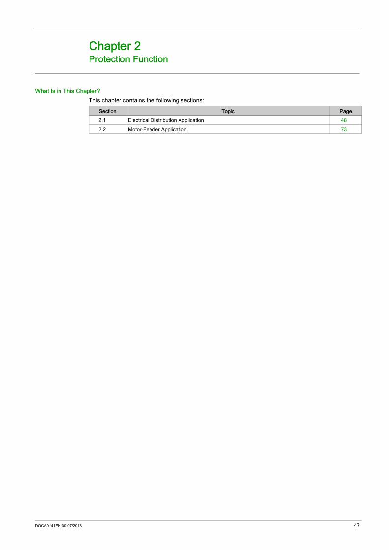
What Is in This Chapter?This chapter contains the following sections:
Section Topic Page2.1 Electrical Distribution Application 482.2 Motor-Feeder Application 73
DOCA0141EN-00 07/2018 47

Protection Function
Electrical Distribution Application
Section 2.1Electrical Distribution Application
What Is in This Section?This section contains the following topics:
Topic PageElectrical Distribution Protection 49Long-Time Protection 53Short-Time Protection 56Instantaneous Protection 58Ground-Fault Protection 59Earth-Leakage Protection 62Neutral Protection 67Zone Selective Interlocking (ZSI) 70Using the ZSI Function with Compact NSX Circuit Breakers 71
48 DOCA0141EN-00 07/2018

Protection Function
Electrical Distribution Protection
PresentationMicrologic 5, 6, and 7 trip units provide protection against overcurrents, ground-fault currents, and earth-leakage currents for commercial or industrial applications.Micrologic 5, 6, and 7 trip units offer protection characteristics that comply with the requirements of standard IEC/EN 60947-2. For more information, refer to Compact NSX - Circuit Breakers and Switch-Disconnectors 100–630 A - User Guide (see page 8).
DescriptionWhen choosing the Micrologic trip unit to use, take account of: Overcurrents (overloads and short-circuits) Ground-fault current or earth-leakage current Conductors that need protection The presence of harmonic currents Coordination between the devices
Selectivity Between DevicesCoordination between the upstream and downstream devices, especially selectivity, is essential to optimize continuity of service. The large number of options for setting the protection functions on Micrologic 5, 6, and 7 trip units improves the natural coordination between Compact NSX circuit breakers. For more information, refer to Compact NSX & NSXm Catalogue (see page 8).Three selectivity techniques can be used:1. Current selectivity, which corresponds to staging of the long-time protection pickup2. Time selectivity, which corresponds to staging of the short-time protection pickup3. Energy selectivity, which corresponds to staging of the circuit breaker energy levels: this applies for very
high intensity short-circuit currents.
Selectivity RulesThe selectivity rules depend on: The type of trip unit on the circuit breakers installed upstream and downstream: electronic or thermal-
magnetic. The accuracy of the settings.
DOCA0141EN-00 07/2018 49

Protection Function
Selectivity of Overload ProtectionFor overload protection, the selectivity rules between electronic trip units are as follows: 1. Current selectivity: A ratio of 1.3 between the Ir pickup for long-time protection of the trip unit on the upstream circuit
breaker Q1 and that of the trip unit on the downstream circuit breaker Q2 is usually sufficient. The tr time delay for long-time protection of the trip unit on the upstream circuit breaker Q1 is identical
or higher than that of the trip unit on the downstream circuit breaker Q2.2. Time selectivity: A ratio of 1.5 between the Isd pickup for short-time protection of the trip unit on the upstream circuit
breaker Q1 and that of the trip unit on the downstream circuit breaker Q2 is usually sufficient. The tsd time delay for short-time protection of the trip unit on the upstream circuit breaker Q1 is higher
than that of the trip unit on the downstream circuit breaker Q2. If the upstream circuit breaker is in position I2t OFF, the downstream circuit breakers must not be in
position I2t ON.3. Energy selectivity: Energy selectivity is provided by the circuit breaker design and build characteristics. The selectivity
limit can only be guaranteed by the manufacturer. For circuit breakers in the Compact NSX circuit breakers range, a ratio of 2.5 between the upstream
circuit breaker Q1 and that of the downstream circuit breaker Q2 guarantees total selectivity.
Ground-Fault Protection SelectivityFor ground-fault protection, only the rules for time selectivity should be applied to the protection Ig pickup and tg time delay: A ratio of 1.3 between the Ig pickup for ground-fault protection of the trip unit on the upstream circuit
breaker Q1 and that of the trip unit on the downstream circuit breaker Q2 is usually sufficient. The tg time delay for ground-fault protection of the trip unit on the upstream circuit breaker Q1 is higher
than that of the trip unit on the downstream circuit breaker Q2. If the upstream circuit breaker is in position I2t OFF, the downstream circuit breakers must not be in
position I2t ON.
Earth-Leakage Protection SelectivityFor earth-leakage protection, only the rules for time selectivity should be applied to the protection IΔn pickup and Δt time delay: A ratio of 3 between the IΔn pickup for earth-leakage protection of the trip unit on the upstream circuit
breaker Q1 and that of the trip unit on the downstream circuit breaker Q2 should be applied. The Δt time delay for earth-leakage protection of the trip unit on the upstream circuit breaker Q1 is
higher than that of the trip unit on the downstream circuit breaker Q2.
Selectivity LimitDepending on the staging of circuit breaker ratings and protection function settings, selectivity can be: Limited (partial selectivity) up to a value Is of the short-circuit current Total (total selectivity), performed irrespective of the value of the short-circuit current
Selectivity TableSchneider Electric provides selectivity tables showing the type of selectivity (partial or total) between each circuit breaker for its entire range of circuit breakers. These selectivity tables are tested in accordance with the recommendations of standard IEC/EN 60947-2. For more information, refer to Compact NSX & NSXm Catalogue (see page 8).
50 DOCA0141EN-00 07/2018

Protection Function
Micrologic 5 Trip Unit
Micrologic 6 Trip Unit
Micrologic 7 Trip Unit with Integrated Earth-Leakage Protection
Setting the ProtectionSet the protection functions: On the Micrologic trip unit, by using the adjustment dials and the keypad (depending on the protection
function and the Micrologic type) With Ecoreach software (password-protected) By sending a setting command using the communication network (password-protected)
Micrologic 5 trip units provide the following protection functions: Long-time overcurrent protection (Ir, tr) Short-time overcurrent protection (Isd, tsd) Instantaneous overcurrent protection (Ii)
Micrologic 6 trip units provide the following protection functions: Long-time overcurrent protection (Ir, tr) Short-time overcurrent protection (Isd, tsd) Instantaneous overcurrent protection (Ii) Ground-fault protection (Ig, tg)
Micrologic 7 trip units provide the following protection functions: Long-time overcurrent protection (Ir, tr) Short-time overcurrent protection (Isd, tsd) Instantaneous overcurrent protection (Ii) Earth-leakage protection (IΔn, Δt)
DOCA0141EN-00 07/2018 51

Protection Function
Integrated Instantaneous ProtectionIn addition to the adjustable instantaneous protection, Micrologic trip units for electrical distribution protection feature a SELLIM non-adjustable integrated instantaneous protection which can improve selectivity.
Reflex TrippingIn addition to the protection functions integrated in the Micrologic trip units, Compact NSX circuit breakers have reflex protection. This system breaks very high fault currents by mechanically tripping the device with a “piston” actuated directly by the pressure produced in the circuit breaker from a short-circuit. This piston operates the opening mechanism, resulting in ultra-fast circuit breaker tripping.
52 DOCA0141EN-00 07/2018

Protection Function
Long-Time Protection
PresentationLong-time protection on Micrologic 5, 6, and 7 trip units protects electrical distribution applications against overload currents. It is identical for Micrologic 5, 6, and 7 trip units.
Operating Principle
Long-time protection is I2t IDMT (Inverse Definite Minimum Time): It incorporates the thermal image function. It is set with the Ir pickup and as the tr trip time delay.
Setting the Long-Time ProtectionSet the Ir pickup as follows: With the Micrologic trip unit Ir dial to preset the value and the keypad to fine-tune the value With Ecoreach software (password-protected) By sending a setting command using the communication network (password-protected)Set the time delay tr as follows: With the keypad on the Micrologic trip unit With Ecoreach software (password-protected) By sending a setting command using the communication network (password-protected)
Ir Pickup Setting ValuesThe long-time protection tripping range is 1.05–1.20 Ir according to standard IEC/EN 60947-2.The default Ir pickup setting value is the maximum dial position In.The following table shows the Ir pickup value preset on the dial:
The accuracy range is + 5%/+ 20%.Use the keypad to fine-tune the setting, in increments of 1 A: The setting range maximum is the preset value of the dial. The range minimum is 0.9 times the minimum preset value (for the 400 A rating, the setting range
minimum is 100 A or 0.625 x Ir).Example: A Micrologic 5.2 trip unit rated In = 250 A is preset by the dial at 140 A: The minimum preset value is 100 A The keypad fine-tuning range is 90–140 A
The long-time protection settings are: Ir: long-time protection pickup tr: long-time protection time delay
In rating Preset values of Ir (A) depending on the trip unit In rating and the dial position 40 A 18 18 20 23 25 28 32 36 40100 A 40 45 50 55 63 70 80 90 100160 A 63 70 80 90 100 110 125 150 160250 A 100 110 125 140 150 175 200 225 250400 A 160 180 200 230 250 280 320 360 400630 A 250 280 320 350 400 450 500 570 630
DOCA0141EN-00 07/2018 53

Protection Function
tr Time Delay Setting ValuesThe setting value displayed is the value of the trip time delay for a current of 6 x Ir.The default tr time delay setting value is 0.5 (minimum value) that is, 0.5 second at 6 x Ir.The following table shows the value of the trip time delay (in seconds) according to the current in the load for the setting values displayed on-screen:
The accuracy range is -20%/+0%.
Thermal ImageThe trip unit uses the calculation of a thermal image to evaluate the conductor heat rise and precisely monitor the thermal state of the conductors.Example:Comparison of the heat rise calculation without thermal image (diagram A) and with thermal image (diagram B):
0 Instantaneous current (cyclical) in the load1 Conductor temperature2 Current calculated without thermal image (diagram A), with thermal image (diagram B) 3 Long-time protection pickup: Ir
Trip unit without thermal image: On each current pulse, the trip unit only considers the thermal effect on the pulse under consideration. No tripping occurs despite the build-up in conductor heat rise.
Trip unit with thermal image: The trip unit adds the thermal effect of successive current pulses. Tripping occurs based on the actual thermal state of the conductor.
Current in the load tr Trip time delay per setting value0.5 1 2 4 8 16
1.5 x Ir 15 s 25 s 50 s 100 s 200 s 400 s6 x Ir 0.5 s 1 s 2 s 4 s 8 s 16 s7.2 x Ir 0.35 s 0.7 s 1.4 s 2.8 s 5.5 s 11 s
54 DOCA0141EN-00 07/2018

Protection Function
Conductor Heat Rise and Tripping CurvesUse the analysis of the equation of heat rise in a conductor, through which a current I runs, to determine the nature of physical phenomena: For low- or medium-intensity currents (I < Ir), the conductor equilibrium temperature (for an infinite time)
only depends on the current quadratic demand value (see page 100). The limit temperature corresponds to a limit current (Ir pickup for trip unit long-time protection).
For low overcurrents (Ir < I < Isd), the conductor temperature only depends on the I2t energy provided by the current. The limit temperature is an I2t IDMT curve.
For high overcurrents (I > Isd), the phenomenon is identical if the I2t function of the short-time protection is active (I2t ON) (see page 57).
The following figure (in double log scales) represents a heat rise curve A (for an equilibrium temperature θ) and a tripping curve B (for the limit temperature θL):
1 Low intensity current zone2 Low overcurrent zone
Thermal MemoryMicrologic 5, 6, and 7 trip units incorporate the thermal memory function which ensures that the conductors are cooled even after tripping. Cooling lasts for 20 minutes before or after tripping.
DOCA0141EN-00 07/2018 55

Protection Function
Short-Time Protection
PresentationShort-time protection on Micrologic 5, 6, and 7 trip units protects all types of electrical distribution applications against short-circuit currents.It is identical for Micrologic 5, 6, and 7 trip units.
Operating Principle Short-time protection is definite time: It incorporates the possibility of an I2t inverse time curve function. It is set using the Isd pickup and the tsd trip time delay.
Setting the Short-Time Protection (Micrologic 5)Set the Isd pickup: With the Micrologic trip unit Isd dial to preset the value and the keypad to fine-tune the value With Ecoreach software (password-protected) By sending a setting command using the communication network (password-protected)Set the tsd time delay: With the keypad on the Micrologic trip unit With Ecoreach software (password-protected) By sending a setting command using the communication network (password-protected)
The tsd time delay setting includes activation/deactivation of the I2t function.
Setting the Short-Time Protection (Micrologic 6 and 7) Set the Isd pickup and tsd time delay: With the keypad on the Micrologic trip unit With Ecoreach software (password-protected) By sending a setting command using the communication network (password-protected)
The tsd time delay setting includes activation/deactivation of the I2t function.
Isd Pickup Setting ValuesThe Isd pickup setting value is in multiples of Ir.The default Isd pickup setting value is 1.5 x Ir (minimum dial value).The following table shows the setting values (preset by a dial) and setting ranges (set on the keypad) of the Isd pickup:
The accuracy range is +/-10%.
The short-time protection settings are: Isd: short-time protection pickup tsd: short-time protection time delay I2t: inverse time curve function (ON or OFF)
Type of setting Value or setting range (x Ir)Preset by a dial(Micrologic 5)
1.5 2 3 4 5 6 7 8 10
Setting range on the keypad (1)
Increment: 0.5 x Ir 1.5 1.5–2 1.5–3 1.5–4 1.5–5 1.5–6 1.5–7 1.5–8 1.5–10
(1) For Micrologic 6 and 7 trip units, the setting range value on the keypad is 1.5–10 x Ir.
56 DOCA0141EN-00 07/2018

Protection Function
tsd Time Delay Setting Values
The following table indicates the setting values for the tsd time delay in seconds (s) with the I2t function active (I2t ON) or not active (I2t OFF). The associated hold and breaking times are shown in milliseconds (ms):
The default tsd time delay setting value is 0 s with I2t OFF.
I2t Inverse Time Curve Function
Use the I2t inverse time curve function to improve circuit breaker coordination. Use it when a protection device using inverse time only is installed downstream, for example a fuse protection device.Example:The following graphs illustrate an example of selective coordination between a Compact NSX630 circuit breaker upstream, and a gG-250 A fuse downstream (calculation performed by the Ecodial software).
I2t OFF I2t ON
Activate the I2t function (I2t ON) on the short-time protection to provide coordination.
Function Setting value
tsd with I2t OFF (s) 0 0.1 0.2 0.3 0.4
tsd with I2t ON (s) – 0.1 0.2 0.3 0.4
Hold time (ms) 20 80 140 230 350Maximum breaking time (ms) 80 140 200 320 500
DOCA0141EN-00 07/2018 57

Protection Function
Instantaneous Protection
PresentationInstantaneous protection on Micrologic 5, 6, and 7 trip units protects all types of electrical distribution applications against very high short-circuit currents.It is identical for Micrologic 5, 6, and 7 trip units.
Operating Principle Instantaneous protection is definite time, set as Ii pickup and without a time delay.
Setting the Instantaneous Protection Set the Ii pickup: With the keypad on the Micrologic trip unit With Ecoreach software (password-protected) By sending a setting command using the communication network (password-protected)
Ii Pickup Setting ValuesThe Ii pickup setting value is in multiples of In.The default Ii pickup setting value is 1.5 x In (minimum value).The following table shows the setting ranges and increments according to the Micrologic trip unit In rating.
The accuracy range is +/-10%.The hold time is 10 ms.The maximum breaking time is 50 ms.
The instantaneous protection setting is: Ii: instantaneous protection pickup
Trip unit In rating Setting range Increments100 A and 160 A 1.5–15 x In 0.5 x In250 A and 400 A 1.5–12 x In 0.5 x In630 A 1.5–11 x In 0.5 x In
58 DOCA0141EN-00 07/2018

Protection Function
Ground-Fault Protection
PresentationGround-fault protection on Micrologic 6 trip units protects all types of electrical distribution applications against ground-fault currents in the TN-S system. For more information on ground-fault currents, refer to Compact NSX - Circuit Breakers and Switch-Disconnectors 100–630 A - User Guide (see page 8).
Operating Principle Ground-fault protection is definite time: It includes the possibility of an I2t inverse time curve function. Set as Ig pickup and as tg trip time delay.
Setting the Ground-Fault ProtectionSet the Ig pickup: With the Micrologic 6 trip unit Ig dial to preset the value and with the keypad to fine-tune the value With Ecoreach software (password-protected) By sending a setting command using the communication network (password-protected)Set the tg time delay: With the keypad on the Micrologic 6 trip unit With Ecoreach software (password-protected) By sending a setting command using the communication network (password-protected)
The tg time delay setting includes activation/deactivation of the I2t function.
The ground-fault protection settings are: Ig: ground-fault protection pickup tg: ground-fault protection time delay I2t: ground-fault protection I2t curve in ON or OFF
position
DOCA0141EN-00 07/2018 59

Protection Function
Ig Pickup Setting ValuesThe Ig pickup setting value is in multiples of In.The default Ig pickup setting value is the same as the minimum value read on the dial: 0.40 x In for trip units rated 40 A 0.20 x In for trip units rated > 40 A Ground-fault protection can be deactivated by setting the Ig dial to the OFF position.Ground-fault protection can be reactivated even with the Ig dial in the OFF position: By fine-tuning on the keypad With Ecoreach software (password-protected) By sending a setting command using the communication network (password-protected)The following two tables specify the setting values (preset by a dial) and setting ranges (set on the keypad.)On the keypad, the increment is 0.05 x In.For trip units rated 40 A
For trip units rated > 40 A
The accuracy range is +/-10%.
tg Time Delay Setting ValuesThe tg time delay setting value is in seconds. The hold and breaking times are in milliseconds.
The default tg time delay setting value is 0 s with I2t OFF.
The following table shows the setting values of tg time delay in seconds (s) with the I2t function active (I2t ON) or not active (I2t OFF). The associated hold and breaking times are shown in milliseconds (ms):
I2t Inverse Time Curve Function
The I2t inverse time curve function for ground-fault protection operates in the same way as the I2t inverse time curve function for short-time protection (see page 57).
Type of setting Value or setting range (x In)Preset by a dial 0.40 0.40 0.50 0.60 0.70 0.80 0.90 1 OFFSetting range on the keypad
0.40 0.40 0.4–0.5 0.4–0.6 0.4–0.7 0.4–0.8 0.4–0.9 0.4–1 0.4–1 + OFF
Type of setting Value or setting range (x In)Preset by a dial 0.20 0.30 0.40 0.50 0.60 0.70 0.80 1 OFFSetting range on the keypad
0.20 0.2–0.3 0.2–0.4 0.2–0.5 0.2–0.6 0.2–0.7 0.2–0.8 0.2–1 0.2–1 + OFF
Function Setting value
tg with I2t OFF (s) 0 0.1 0.2 0.3 0.4
tg with I2t ON (s) – 0.1 0.2 0.3 0.4
Hold time (ms) 20 80 140 230 360Maximum breaking time (ms) 80 140 200 320 500
60 DOCA0141EN-00 07/2018

Protection Function
Testing the Ground-Fault ProtectionThe ground-fault protection can be tested to check the electronic tripping function of the trip unit. Use the keypad of the Micrologic 6 trip unit to perform this test.
The ground-fault protection test can be performed with the padlock locked or unlocked . Follow these steps to test and reset the ground-fault protection on Micrologic 6 trip units.
Step Action Display1 Provide a power supply to the trip unit so that
the screen displays the result of the test after the circuit breaker trips.
–
2 Select the Instantaneous measurement readout mode (the display is the most heavily loaded phase, in this example Phase 2).
3 Select the ground-fault current measurement screen (the value is a percentage of the Ig setting).
4 Access the ground-fault protection test function by pressing OK.The tESt pictogram appears and the OK pictogram blinks.
5 Prompt the ground-fault protection test by pressing OK.The circuit breaker trips. The ground-fault protection trip screen is displayed.
6 Acknowledge the ground-fault trip screen by pressing OK.The Reset? OK pictogram blinks.
7 Confirm by pressing OK again.The confirmation OK displays for 2 s.
DOCA0141EN-00 07/2018 61

Protection Function
Earth-Leakage Protection
PresentationEarth-leakage protection on Micrologic 7 trip units provides protection against low intensity fault currents to ground for: All types of electrical distribution applications People, according to the earth-leakage protection setting usedEarth-leakage protection is designed for installations with TT or TN-S grounding system.The Micrologic 7 electronic trip unit is available in two versions for earth-leakage detection: The Trip version trips when earth-leakage is detected. The Alarm version measures the earth-leakage current and indicates an earth-leakage fault on the
display screen.
Operating PrincipleEarth-leakage protection is definite time.The earth-leakage protection threshold IΔn sets the level of earth-leakage current at which the circuit breaker trips when reaching the earth-leakage protection time delay Δt.
Setting the Earth-Leakage ProtectionSet the IΔn pickup with the Micrologic 7 trip unit IΔn dial.Set the Δt time delay as follows: With the keypad on the Micrologic 7 trip unit With Ecoreach software (password-protected)
IΔn Pickup Setting Values
The accuracy range is +/-10%.
Δt Time Delay Setting ValuesWhen IΔn is set to the 30 mA, the earth-leakage protection acts immediately (instantaneous tripping), whatever the setting of the Δt time delay.For other IΔn values (> 30 mA), the Δt time delay can be set to one of the following values: 0 s 60 ms 150 ms 500 ms 1 second
The earth-leakage protection settings are: IΔn: earth-leakage protection pickup Δt: earth-leakage protection time delay
Trip unit rating In (A) Pickup IΔnIΔn dial position 1 2 3 4 5 6 7 8 940, 100, 160, and 250 A
30 mA 30 mA 100 mA 300 mA 500 mA 1 A 3 A 5 A OFF
400 and 570 A (1) 300 mA 300 mA 500 mA 1 A 3 A 5 A 10 A 10 A OFF
(1) Maximum setting at 570 A for thermal reasons, to be adapted with breaking block up to 630 A
62 DOCA0141EN-00 07/2018
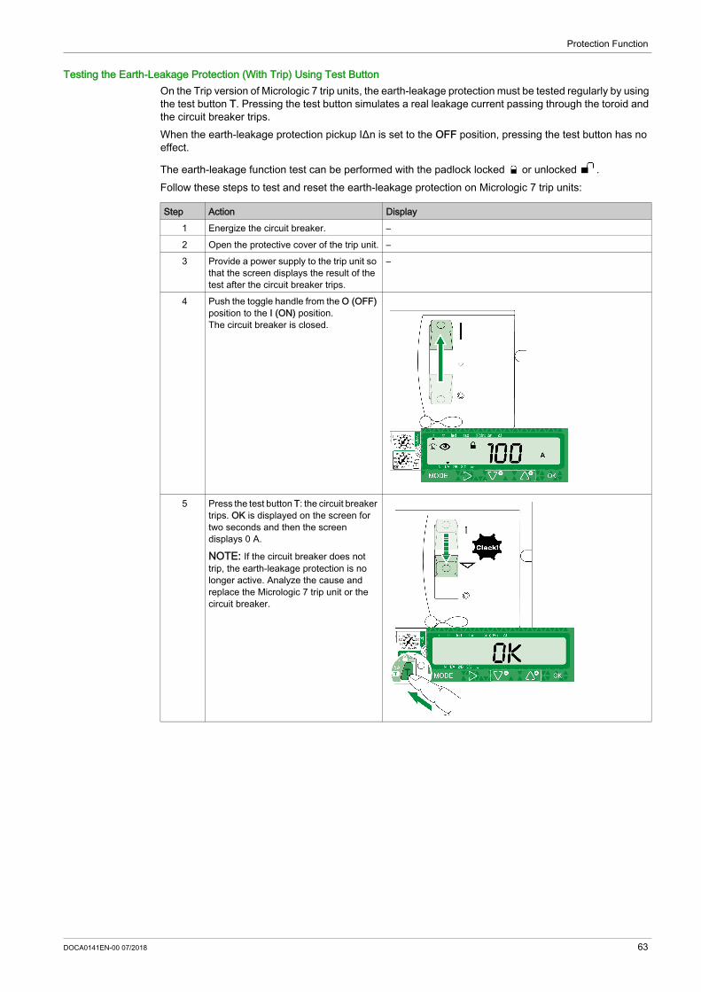
Protection Function
Testing the Earth-Leakage Protection (With Trip) Using Test ButtonOn the Trip version of Micrologic 7 trip units, the earth-leakage protection must be tested regularly by using the test button T. Pressing the test button simulates a real leakage current passing through the toroid and the circuit breaker trips.When the earth-leakage protection pickup IΔn is set to the OFF position, pressing the test button has no effect.
The earth-leakage function test can be performed with the padlock locked or unlocked .Follow these steps to test and reset the earth-leakage protection on Micrologic 7 trip units:
Step Action Display1 Energize the circuit breaker. –2 Open the protective cover of the trip unit. –3 Provide a power supply to the trip unit so
that the screen displays the result of the test after the circuit breaker trips.
–
4 Push the toggle handle from the O (OFF) position to the I (ON) position.The circuit breaker is closed.
5 Press the test button T: the circuit breaker trips. OK is displayed on the screen for two seconds and then the screen displays 0 A.
NOTE: If the circuit breaker does not trip, the earth-leakage protection is no longer active. Analyze the cause and replace the Micrologic 7 trip unit or the circuit breaker.
DOCA0141EN-00 07/2018 63

Protection Function
6 Push the toggle handle from the (Trip) position to the O (OFF) position.
7 Push the toggle handle from the O (OFF) position to the I (ON) position.The circuit breaker is closed.
Step Action Display
64 DOCA0141EN-00 07/2018

Protection Function
Testing the Earth-Leakage Alarm (Without Trip) Using Test ButtonOn the Alarm version of the Micrologic 7 trip unit, the earth-leakage alarm can be tested by using the test button T. Pressing the test button simulates a real leakage current passing through the toroid. The circuit breaker does not trip.When the earth-leakage alarm pickup IΔn is set to the OFF position, pressing the test button has no effect.
The earth-leakage function test can be performed with the padlock locked or unlocked .Follow these steps to test the earth-leakage alarm on Micrologic 7 AL trip units:
Step Action Display1 Energize the circuit breaker. –2 Open the protective cover of the trip unit. –3 Provide a power supply to the trip unit. –4 Push the toggle handle from the O (OFF)
position to the I (ON) position.The circuit breaker is closed.
5 Press the test button T: OK is displayed on the screen for two seconds, and then the previous screen is displayed.
NOTE: If nOK is displayed on the screen, the earth-leakage alarm is no longer active. Replace the Micrologic 7 AL trip unit.
DOCA0141EN-00 07/2018 65

Protection Function
Testing the Earth-Leakage Function (Without Trip) Using Keypad OnlyOn the Trip and Alarm versions of the Micrologic 7 trip unit, the earth-leakage tripping chain (or earth-leakage detection for the Alarm version) (except mechanism and pole operation) can be tested, without tripping the circuit breaker, by using the keypad.
The earth-leakage function test can be performed with the padlock locked or unlocked . Follow these steps to test the earth-leakage protection alarm on Micrologic 7 AL trip units:
Earth-Leakage Test HistoryThe last ten earth-leakage tests are recorded in an earth-leakage test history (see page 152). Tests performed using the T test button and tests using the keypad are logged in the same history.The history records: Type of test: with trip or without trip Date of test Result of test (OK or nOK)The earth-leakage test history can be consulted: With Ecoreach software. On a remote controller using the communication network.
Resetting the Circuit Breaker After an Earth-Leakage Fault DetectionResetting the earth-leakage function after an earth-leakage fault detection (with or without trip) depends on the version: For the Trip version, reset the circuit breaker by moving the handle from Trip to O (OFF) position, and
then to I (ON) position. Acknowledge the earth-leakage trip screen by pressing OK. For the Alarm version, acknowledge the earth-leakage trip screen by pressing OK.Resetting the earth-leakage function after an earth-leakage protection test is described in the procedure for each test.
Step Action Using Display1 Select the earth-leakage measurement
screen.
2 Access the earth-leakage function test by pressing OK.The tESt pictogram appears and the OK pictogram blinks.
3 Prompt the earth-leakage function test by pressing OK.The result of the test (OK or nOK) is displayed on the screen after two seconds.
NOTE: If nOK is displayed on the screen, test the earth-leakage function by using the test button T.
4 After two seconds the screen returns to the screen displayed before the test
– –
66 DOCA0141EN-00 07/2018

Protection Function
Neutral Protection
PresentationNeutral protection on Micrologic 5, 6, and 7 trip units protects all types of electrical distribution applications against overload and short-circuit currents.It is available on: Micrologic 5, 6, and 7 trip units for 4-pole circuit breakers Micrologic 5 and 6 trip units with ENCT option for 3-pole circuit breakers
DescriptionNormally, the phase protection protects the neutral conductor (if it is distributed and identical to the phases in size, that is, full neutral).The neutral must have specific protection if: It is reduced in size compared to the phases Nonlinear loads generating third order harmonics (or multiples thereof) are installedIt may be necessary to switch off the neutral for operational reasons (multiple source diagram) or safety reasons (working with power off).To summarize, the neutral conductor can be: Non-distributed (3-pole circuit breaker) Distributed, not switched off and not protected (3-pole circuit breaker) Distributed, not switched off but protected (3-pole circuit breaker with ENCT option) Distributed, switched off and protected (4-pole circuit breaker)Compact NSX circuit breaker trip units are suitable for all protection types.
Operating Principle Neutral protection has the same characteristics as phase protection: Its pickup is in proportion with the long-time Ir and short-time Isd protection pickups. It has the same trip time delay values as the long-time Ir and short-time Isd protections. Its instantaneous protection is identical.
Circuit breaker Possible types Neutral protection3-pole circuit breaker 3P, 3D None3-pole circuit breaker with ENCT option
3P, 3D None3P, 3D + N/2 Half neutral3P, 3D + N Full neutral3P, 3D + OSN Oversized neutral
4-Pole Circuit Breaker 4P, 3D None4P, 3D + N/2 Half neutral4P, 4D Full neutral4P, 4D + OSN Oversized neutral
P: Pole; D: Trip unit; N: Neutral protection
The neutral protection settings are: Ir: long-time protection pickup tr: long-time protection time delay IN: neutral protection pickup
DOCA0141EN-00 07/2018 67

Protection Function
Setting the Neutral Protection4-pole trip unitSet the IN pickup: With the keypad on the Micrologic trip unit With Ecoreach software (password-protected) By sending a setting command using the communication network (password-protected)3-pole trip unitSet the neutral declaration and the IN pickup: With the keypad on the Micrologic trip unit With Ecoreach software (password-protected) By sending a setting command using the communication network (password-protected)
Neutral Protection Setting ValueMicrologic 5, 6, and 7 trip units incorporate the OSN (Oversized Neutral) function, which manages protection of the neutral conductor when third-order harmonic currents (and multiples thereof) are present.The following table shows the setting values of the neutral long-time protection and neutral short-time protection pickups, according to the value of the IN/Ir function:
The setting values are identical for the phases, the neutral long-time, and short-time protection time delays.The following table details the setting values of the neutral protection pickups (set to OSN) according to the phase protection pickup Ir setting and the In rating of the 4-pole trip unit.
Selection of the ENCT OptionThe ENCT option is an external neutral CT for a 3-pole Micrologic 5 or 6 trip unit.The following table indicates the part number for the ENCT option installed according to the In rating of the Micrologic trip unit or the need for OSN protection:
IN/Ir function Long-time pickup value Ir(IN) Short-time pickup value Isd(IN)OFF N/A N/A
0.5 (1) Ir/2 Isd/2
1 Ir Isd(1) For the Micrologic 7 trip unit with 40 A rating, the IN/Ir = 0.5 setting is not available.
Ir/In values Long-time pickup value Ir(IN) Short-time pickup value Isd(IN)Ir/In < 0.63 1.6 x Ir 1.6 x Isd0.63 < Ir/In < 1 In In x Isd/Ir
In rating (A) Neutral protection limited to In OSN neutral protection > In40 LV429521 LV429521100 LV429521 LV429521160 LV430563 LV430563250 LV430563 LV432575400 LV432575 LV432575630 LV432575 No (1)
(1) For the 630 A rating, the OSN function is limited to In (= 630 A).
68 DOCA0141EN-00 07/2018

Protection Function
Installing the ENCT Option
NOTE: If the ENCT option is declared before its installation, the Micrologic trip unit trips and displays the ENCT screen. Either install the ENCT option or connect a jumper between terminals T1 and T2 on the Micrologic trip unit. Clear the ENCT screen by pressing the OK key twice (enter and confirm).
Step Action1 Connect the neutral conductor to the ENCT option primary (terminals H1, H2).2 Remove (if existing) the jumper, between terminals T1 and T2 of the Micrologic trip unit.3 Connect the ENCT option secondary (terminals T1, T2) to terminals T1 and T2 of the Micrologic trip unit.4 Declare the ENCT option when setting the protection functions for the Micrologic trip unit.
DOCA0141EN-00 07/2018 69

Protection Function
Zone Selective Interlocking (ZSI)
PresentationUse zone selective interlocking (ZSI) to reduce the electrodynamic stress on equipment when using selective coordination.
Principle of the ZSI FunctionZSI improves coordination by being selective about the position of the electrical fault. A signal wire links the installed circuit breaker trip units and manages the trip time delay for upstream circuit breaker Q1 according to the electrical fault position.The trip units on circuit breakers Q1 and Q2 have the same time delay settings as with selective coordination.
If an electrical fault occurs downstream of downstream circuit breaker Q2 (diagram 3), the trip units on circuit breakers Q1 and Q2 detect the electrical fault simultaneously. The trip unit on circuit breaker Q2 sends a restraint signal to the trip unit on circuit breaker Q1, which remains set on its time delay tsd. Circuit breaker Q2 trips and clears the electrical fault (instantaneously if circuit breaker Q2 is not delayed). The other users downstream of circuit breaker Q1 still have power, the energy availability is optimized.
If an electrical fault occurs downstream of circuit breaker Q1 (diagram 4), the trip unit on circuit breaker Q1 does not receive a restraint signal from the trip unit on circuit breaker Q2. Time delay tsd is therefore inhibited. Circuit breaker Q1 trips and clears the electrical fault on the equipment instantaneously. The electrodynamic stress created by the short-circuit current on the equipment is reduced to the minimum.
The ZSI function can be used to optimize the availability of energy (just like selective coordination) and reduce electrodynamic stress on the equipment. The ZSI function is applicable to both short-time and ground-fault protection.
70 DOCA0141EN-00 07/2018
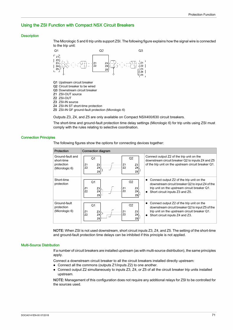
Protection Function
Using the ZSI Function with Compact NSX Circuit Breakers
Description The Micrologic 5 and 6 trip units support ZSI. The following figure explains how the signal wire is connected to the trip unit:
Q1 Upstream circuit breakerQ2 Circuit breaker to be wiredQ3 Downstream circuit breakerZ1 ZSI-OUT sourceZ2 ZSI-OUT Z3 ZSI-IN sourceZ4 ZSI-IN ST short-time protectionZ5 ZSI-IN GF ground-fault protection (Micrologic 6)
Outputs Z3, Z4, and Z5 are only available on Compact NSX400/630 circuit breakers.The short-time and ground-fault protection time delay settings (Micrologic 6) for trip units using ZSI must comply with the rules relating to selective coordination.
Connection PrinciplesThe following figures show the options for connecting devices together:
NOTE: When ZSI is not used downstream, short circuit inputs Z3, Z4, and Z5. The setting of the short-time and ground-fault protection time delays can be inhibited if this principle is not applied.
Multi-Source DistributionIf a number of circuit breakers are installed upstream (as with multi-source distribution), the same principles apply.Connect a downstream circuit breaker to all the circuit breakers installed directly upstream: Connect all the commons (outputs Z1/inputs Z2) to one another. Connect output Z2 simultaneously to inputs Z3, Z4, or Z5 of all the circuit breaker trip units installed
upstream.NOTE: Management of this configuration does not require any additional relays for ZSI to be controlled for the sources used.
Protection Connection diagramGround-fault and short-time protection (Micrologic 6)
Connect output Z2 of the trip unit on the downstream circuit breaker Q2 to inputs Z4 and Z5 of the trip unit on the upstream circuit breaker Q1.
Short-time protection
Connect output Z2 of the trip unit on the downstream circuit breaker Q2 to input Z4 of the trip unit on the upstream circuit breaker Q1.
Short circuit inputs Z3 and Z5.
Ground-fault protection (Micrologic 6)
Connect output Z2 of the trip unit on the downstream circuit breaker Q2 to input Z5 of the trip unit on the upstream circuit breaker Q1.
Short circuit inputs Z4 and Z3.
DOCA0141EN-00 07/2018 71

Protection Function
Connection Wire CharacteristicsThe following table indicates the characteristics of the inter-device signal wire:
NOTE: When using the ZSI to connect Compact NSX circuit breakers with Masterpact or Compact NS circuit breakers, add an RC filter (part number LV434212) to the circuit by a Masterpact or Compact NS circuit breaker. For more information, refer to Compact NSX & NSXm Catalogue (see page 8).The following figure shows the connection of the RC filter (part number LV434212).
Testing the ZSI FunctionTest connection and operation of ZSI using the USB maintenance interface and the LTU software.
Characteristics ValuesImpedance 2.7 Ω per 300 mMaximum length 300 mType of cable Shielded twisted (Belden 8441 or equivalent)Permissible conductor cross-section 0.4–2.5 mm2
Interconnection limit on inputs Z3, Z4, and Z5 (to downstream devices)
15 devices
Interconnection limit on outputs Z1 and Z2 (to upstream devices)
5 devices
72 DOCA0141EN-00 07/2018

Protection Function
Motor-Feeder Application
Section 2.2Motor-Feeder Application
What Is in This Section?This section contains the following topics:
Topic PageProtection for Motor-Feeders 74Long-Time Protection 78Short-Time Protection 81Instantaneous Protection 82Ground-Fault Protection 83Phase Unbalance Protection 86Motor Jam Protection 88Underload Motor Protection 90Long-Start Motor Protection 91
DOCA0141EN-00 07/2018 73

Protection Function
Protection for Motor-Feeders
PresentationMicrologic 6 E-M trip units on Compact NSX circuit breakers: Provide protection for direct-on-line motor-feeders (direct-on-line starting is the most widely used type
of motor-feeder). Integrate the basic protections (overload, short-circuit, and phase unbalance) for the motor-feeder and
additional protections and/or specific options for motor applications. Allow protection and coordination of the motor-feeder components that comply with the requirements of
standard IEC/EN 60947-2 and IEC/EN 60947-4-1. For more information, refer to Compact NSX - Circuit Breakers and Switch-Disconnectors 100–630 A - User Guide (see page 8).
DescriptionCompact NSX circuit breakers equipped with the Micrologic 6 E-M trip unit can be used to create motor-feeders with two devices.
A Compact NSX circuit breaker equipped with a Micrologic 6 E-M trip unitB Short-circuit protectionC Overload protectionD Ground-fault current protectionE ContactorF SDTAM Module Option
Operating StatesThe Micrologic 6 E-M trip unit considers the application to be operating as soon as the 10% of Ir pickup is crossed in a positive direction by the motor current.Two operating states are considered: Startup state Steady state
Startup StateThe Micrologic 6 E-M trip unit considers the application to be in startup state according to the following criteria: Start: As soon as the 10% of Ir pickup is crossed in a positive direction by the motor current End: As soon as the Id pickup is crossed in a negative direction or at maximum after a td time delay
defined as follows: If long-start protection is not activated (factory setting), the Id pickup equals 1.5 x Ir and the td time
delay equals 10 s (non-adjustable parameters).Exceeding the 10 s time delay does not result in tripping.
If long-start protection is activated (see page 91), the Id pickup equals Ilong and the td time delay equals tlong (adjustable parameters).Exceeding the tlong time delay results in long-start protection tripping.
NOTE: The Micrologic trip unit measurement electronics filter the subtransient state (first current peak of approximately 20 ms on contactor closing). This current peak is not therefore taken into account when assessing whether the Id pickup has been crossed.
74 DOCA0141EN-00 07/2018

Protection Function
Steady StateThe Micrologic 6 E-M trip unit considers the application to be in steady state according to the following criteria: Start: As soon as startup ends End: As soon as the 10% of Ir pickup is crossed in a negative direction by the motor current
Operating DiagramThe following diagram shows the two operating states for a motor application:
1 Compact NSX circuit breaker status (green = ON position)2 Contactor status (green = ON position)3 Current in the motor application4 Operating states: A: Startup state B: Steady state (the active states are shown in green)
Protection FunctionsThe following figure and table define the protection functions for Micrologic 6 E-M trip units:
Each function is reviewed in detail on the following pages.
Item Parameter Description Adjustable0 In Trip unit setting range: Minimum setting/maximum setting = trip unit In
ratingNo
1 Ir Long-time protection pickup L Yes2 Cl Long-time protection trip class Yes3 Isd Short-time protection pickup S Yes4 tsd Short-time protection time delay No5 Ii Instantaneous protection pickup I No6 Ig Ground-fault protection pickup G Yes7 tg Ground-fault protection time delay Yes
Iunbal Phase unbalance protection pickup Yes tunbal Phase unbalance protection time delay Yes
DOCA0141EN-00 07/2018 75
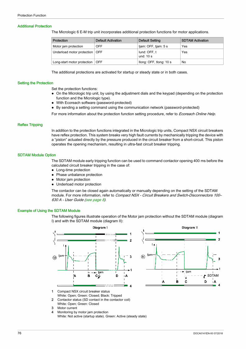
Protection Function
Additional ProtectionThe Micrologic 6 E-M trip unit incorporates additional protection functions for motor applications.
The additional protections are activated for startup or steady state or in both cases.
Setting the ProtectionSet the protection functions: On the Micrologic trip unit, by using the adjustment dials and the keypad (depending on the protection
function and the Micrologic type). With Ecoreach software (password-protected) By sending a setting command using the communication network (password-protected)For more information about the protection function setting procedure, refer to Ecoreach Online Help.
Reflex TrippingIn addition to the protection functions integrated in the Micrologic trip units, Compact NSX circuit breakers have reflex protection. This system breaks very high fault currents by mechanically tripping the device with a “piston” actuated directly by the pressure produced in the circuit breaker from a short-circuit. This piston operates the opening mechanism, resulting in ultra-fast circuit breaker tripping.
SDTAM Module OptionThe SDTAM module early tripping function can be used to command contactor opening 400 ms before the calculated circuit breaker tripping in the case of: Long-time protection Phase unbalance protection Motor jam protection Underload motor protectionThe contactor can be closed again automatically or manually depending on the setting of the SDTAM module. For more information, refer to Compact NSX - Circuit Breakers and Switch-Disconnectors 100–630 A - User Guide (see page 8).
Example of Using the SDTAM ModuleThe following figures illustrate operation of the Motor jam protection without the SDTAM module (diagram Ι) and with the SDTAM module (diagram ΙΙ):
1 Compact NSX circuit breaker status White: Open; Green: Closed; Black: Tripped 2 Contactor status (SD contact in the contactor coil) White: Open; Green: Closed 3 Motor current4 Monitoring by motor jam protection White: Not active (startup state). Green: Active (steady state)
Protection Default Activation Default Setting SDTAM ActivationMotor jam protection OFF Ijam: OFF, tjam: 5 s YesUnderload motor protection OFF Iund: OFF, t
und: 10 sYes
Long-start motor protection OFF Ilong: OFF, tlong: 10 s No
76 DOCA0141EN-00 07/2018
Protection Function
Analysis of Operation The following table describes operation without the SDTAM module (diagram Ι)
The following table describes operation with the SDTAM module (diagram ΙΙ)
The SDTAM module can be set to the OFF position: the application is returned to service manually (by deactivating the SDTAM module power supply).
Event CommentsA Application motor switches to steady state.
Motor jam protection monitoring is activated.B Occurrence of an overload current on the application (for example, rotor braked due to high viscosity
of one of the mixing fluids)The Motor jam protection tjam time delay is actuated as soon as the motor current crosses the Ijam pickup.
C End of Motor jam protection time delay Motor jam protection causes the Compact NSX circuit breaker to trip.
D Application returned to service manually after the motor has cooled and the circuit breaker has closed again.
Event CommentsA Identical to diagram ΙB Identical to diagram ΙC 400 ms before the end of the Motor jam protection time delay, the SDTAM module:
Commands the contactor to open (output OUT2) Sends a fault indication (output OUT1)
Both outputs are activated for a time delay (which can be set between 1 and 15 minutes).D Application contactor returned to service automatically: the time delay allows the motor to cool down.
DOCA0141EN-00 07/2018 77

Protection Function
Long-Time Protection
PresentationLong-time protection on Micrologic 6 E-M trip units protects all types of motor applications against overload currents.
Operating Principle
Long-time protection is I2t IDMT (Inverse Definite Minimum Time): It incorporates the motor thermal image function. It can be configured as the Ir pickup and as the trip class Class.Tripping curve:
NOTE: The SDTAM module early tripping protection function can be used to command contactor opening (see page 76).
Setting the Long-Time ProtectionSet the Ir pickup: With the Micrologic trip unit Ir dial to preset the value and the keypad to fine-tune the value With Ecoreach software (password-protected) By sending a setting command using the communication network (password-protected)Set the trip class Cl: With the keypad on the Micrologic trip unit With Ecoreach software (password-protected) By sending a setting command using the communication network (password-protected)
The long-time protection parameters are: 0: In Trip-unit setting range 1: Ir Long-time protection pickup 2: Cl Long-time protection trip class (according to
standard IEC/EN 60947-4-1)
78 DOCA0141EN-00 07/2018

Protection Function
Ir Pickup Setting ValueThe default Ir pickup setting value is In (maximum dial value).The overload or thermal protection tripping range is 1.05–1.20 x Ir according to standard IEC/EN 60947-2.The Ir pickup is preset by a dial.
The accuracy range is + 5%/+ 20%.Use the keypad to fine-tune the setting, in increments of 1 A: The setting range maximum is the preset value displayed by the dial. The setting range minimum is the minimum preset value. Example:A Micrologic 6 E-M trip unit In = 500 A is preset by the dial at 470 A. The fine-tuning range on the keypad is 250–470 A.
Trip Class Setting ValueThe class is set via the keypad, using any of the four defined values: 5, 10, 20, and 30.The trip class corresponds to the value of the trip time delay for a current of 7.2 x Ir according to standard IEC/EN 60947-4-1.The factory class setting value is 5 (minimum value).The following table shows the value of the trip time delay depending on the current in the load for all four trip classes.
Motor Thermal ImageThe model representing heat rise and cooling in a motor load is identical to that used for the conductors. It is constructed according to the algorithm for calculating the thermal demand but this model takes account of the iron and copper losses.The following figure represents the limit curves for the iron and copper components calculated by the Micrologic 6 E-M trip unit (for class 20):
A Limit temperature curve for copperB Limit temperature curve for ironC Tripping curve (low envelope)
In Rating Preset values of Ir (A) depending on the trip unit In rating and the dial position 25 A 12 14 16 18 20 22 23 24 2550 A 25 30 32 36 40 42 46 47 5080 A 35 42 47 52 57 60 63 72 80150 A 70 80 90 100 110 120 133 140 150220 A 100 120 140 155 170 185 200 210 220320 A 160 180 200 220 240 260 280 300 320500 A 250 280 320 360 380 400 440 470 500
Current in the load Trip class Cl5 10 20 30tr Trip time delay (s)
1.5 x Ir 120 240 400 7206 x Ir 6.5 13.5 26 387.2 x Ir 5 10 20 30
DOCA0141EN-00 07/2018 79

Protection Function
Thermal MemoryMicrologic 6 E-M trip units incorporate a thermal memory which ensures that the conductors are cooled even after tripping: cooling lasts for 20 minutes before or after tripping.
Cooling FanBy default, the motor thermal image is calculated taking account of the fact that the motor is self-cooled (fan mounted on the shaft end).If the motor is force-cooled (forced ventilation), the calculation of the thermal image takes account of the shortest time constants for the cooling calculation.The cooling ventilation parameters (Auto or Moto position) are set on the Micrologic trip unit keypad or using Ecoreach software.
80 DOCA0141EN-00 07/2018

Protection Function
Short-Time Protection
PresentationShort-time protection on Micrologic 6 E-M trip units protects all types of motor applications against short-circuit currents.
Operating PrincipleShort-time protection is definite time. It can be configured as the Isd pickup.Tripping curve:
Setting the Short-Time ProtectionSet the Isd pickup and tsd time delay: With the keypad on the Micrologic trip unit With Ecoreach software (password-protected) By sending a setting command using the communication network (password-protected)
Isd Pickup Setting ValueThe Isd pickup setting value is in multiples of Ir.The default Isd pickup setting value is 5 x Ir (minimum value).The pickup setting range on the keypad is 5–13 x Ir. The increment is 0.5 x Ir.The accuracy range is +/-15%.
tsd Time Delay ValueThe time delay cannot be adjusted. The hold time is 20 ms. The maximum breaking time is 60 ms.
The short-time protection parameters are: 1: Ir Long-time protection pick-up 3: Isd Short-time protection pick-up 4: tsd Short-time protection fixed time delay
DOCA0141EN-00 07/2018 81

Protection Function
Instantaneous Protection
PresentationInstantaneous protection on Micrologic 6 E-M trip units protects all types of motor applications against very high intensity short-circuit currents.
Operating Principle Instantaneous protection is fixed: the pickup value is determined by the trip unit rating. Protection is instantaneous.Tripping curve:
Ii Pickup ValueThe Ii pickup value is directly determined by the trip unit In rating and is in x In. Ii pickup value according to the Micrologic trip unit In rating (accuracy range +/-10%).
The hold time is 0 ms.The maximum breaking time is 30 ms.
The instantaneous protection parameters are: 0: In Trip-unit setting range 5: Ii Instantaneous protection pick-up
In rating (A) 25 50 80 150 220 320 500Instantaneous pickup (A) 425 750 1200 2250 3300 4800 7500
82 DOCA0141EN-00 07/2018

Protection Function
Ground-Fault Protection
PresentationGround-fault protection on Micrologic 6 E-M trip units protects all types of motor applications against ground-fault currents in the TN-S system. For more details, refer to Compact NSX - Circuit Breakers and Switch-Disconnectors 100–630 A - User Guide (see page 8).
Operating PrincipleGround-fault protection is definite time. It can be configured as Ig pickup and as tg trip time delay.Tripping curve:
Setting the Ground-Fault ProtectionSet the Ig pickup: With the Micrologic trip unit Ig dial to preset the value and the keypad to fine-tune the value With Ecoreach software (password-protected) By sending a setting command using the communication network (password-protected)Set the tg time delay: With the keypad on the Micrologic trip unit With Ecoreach software (password-protected) By sending a setting command using the communication network (password-protected)
The ground-fault protection parameters are: 0: In Trip unit setting range 6: Ig Ground-fault protection pick-up 7: tg Ground-fault protection time delay
DOCA0141EN-00 07/2018 83

Protection Function
Ig Pickup Setting ValuesThe Ig pickup setting value is in multiples of In.The default Ig pickup setting value is the same as the minimum dial value: 0.60 In for trip units rated 25 A 0.30 In for trip units rated 50 A 0.20 In for trip units rated > 50 AGround-fault protection can be deactivated by setting the Ig dial to the OFF position.Ground-fault protection can be reactivated even with the Ig dial in the OFF position: By fine-tuning on the keypad With Ecoreach software (password-protected) By sending a setting command using the communication network (password-protected)The following three tables specify the setting values (preset by a dial) and setting ranges (set on the keypad): For trip units rated 25 A For trip units rated 50 A For trip units rated > 50 AOn the keypad, the increment is 0.05 x In.Rating 25 A
Rating 50 A
Rating > 50 A
The accuracy range is +/-10%.
tg Time Delay Setting ValuesThe tg time delay setting value is in seconds. The hold and breaking times are in milliseconds.The default tg time delay setting is 0 s.The following table shows tg setting values in second (s) and the associated hold and breaking times in milliseconds (ms):
Type of setting Value or setting range (x In)Preset by a dial 0.60 0.60 0.60 0.60 0.70 0.80 0.90 1 OFFSetting range on the keypad
0.60 0.60 0.60 0.60 0.6–0.7 0.6–0.8 0.6–0.9 0.6–1 0.6–1 + OFF
Type of setting Value or setting range (x In)Preset by a dial 0.30 0.40 0.50 0.60 0.70 0.80 0.90 1 OFFSetting range on the keypad
0.30 0.3–0.4 0.3–0.5 0.3–0.6 0.3–0.7 0.3–0.8 0.3–0.9 0.3–1 0.3–1 + OFF
Type of setting Value or setting range (x In)Preset by a dial 0.20 0.30 0.40 0.50 0.60 0.70 0.80 1 OFFSetting range on the keypad
0.20 0.2–0.3 0.2–0.4 0.2–0.5 0.2–0.6 0.2–0.7 0.2–0.8 0.2–1 0.2–1 + OFF
Function Valuetg (s) 0 0.1 0.2 0.3 0.4Hold time (ms) 20 80 140 230 350Maximum breaking time (ms) 80 140 200 320 500
84 DOCA0141EN-00 07/2018

Protection Function
Testing the Ground-Fault ProtectionThe ground-fault protection can be tested to check the electronic tripping function of the trip unit. Use the keypad of the Micrologic 6 trip unit to perform this test.
The ground-fault protection test can be performed with the padlock locked or unlocked . Follow these steps to test and reset the ground-fault protection on Micrologic 6 trip units.
Step Action Display1 Provide a power supply to the trip unit so that
the screen displays the result of the test after the circuit breaker trips.
–
2 Select the Instantaneous measurement readout mode (the display is the most heavily loaded phase, in this example Phase 2).
3 Select the ground-fault current measurement screen (the value is a percentage of the Ig setting).
4 Access the ground-fault protection test function by pressing OK.The tESt pictogram appears and the OK pictogram blinks.
5 Prompt the ground-fault protection test by pressing OK.The circuit breaker trips. The ground-fault protection trip screen is displayed.
6 Acknowledge the ground-fault trip screen by pressing OK.The Reset? OK pictogram blinks.
7 Confirm by pressing OK again.The confirmation OK displays for 2 s.
DOCA0141EN-00 07/2018 85

Protection Function
Phase Unbalance Protection
PresentationUnbalances of the motor phase currents lead to significant heat rise and braking torques that can cause premature deterioration of the motor. These effects are amplified during startup: protection must be almost immediate.
DescriptionPhase unbalance protection: calculates the current unbalance for each phase, compared to the average current, expressed as a
percentage:
Compares the value of the maximum current unbalance with the Iunbal protection pickup.The following diagram shows a maximum positive unbalance on phase 2:
If the maximum current unbalance value is higher than the phase unbalance protection Iunbal pickup, the tunbal time delay is actuated.Phase unbalance protection cannot be deactivated.Phase unbalance protection is activated during startup and in steady state.
86 DOCA0141EN-00 07/2018

Protection Function
Operating PrincipleThe following figures illustrate the operating possibilities:
1 M Motor current1 D Maximum unbalance of the motor phase currents2 A Monitoring by phase unbalance protection during startup (diagram I)2 B Monitoring by phase unbalance protection in steady state (diagrams II and III) White: Not active; Green: Active
The current unbalance does not fall below the Iunbal pickup before the end of the tunbal time delay: the
phase unbalance protection trips. The behavior of the protection differs according to the motor operating conditions: During startup (diagram I)
A: Activation of startup.B: Activation of protection time delay as soon as the pickup is crossed.C: Protection tripped at the end of the fixed time delay of 0.7 s.
In steady state (diagram II)A: Activation of startup.B: Activation of protection time delay as soon as the pickup is crossed.C: Protection tripped at the end of the adjustable time delay.
The current unbalance falls below the Iunbal pickup before the end of the tunbal time delay. The phase unbalance protection does not trip (diagram III): B: Activation of protection time delay as soon as the pickup is crossed. D: Deactivation of protection.
NOTE: The SDTAM module early tripping protection function can be used to command contactor opening (see page 76).
Setting the ProtectionSet the Iunbal pickup and the tunbal time delay: With the keypad on the Micrologic trip unit With Ecoreach software (password-protected) By sending a setting command using the communication network (password-protected)
Iunbal Pickup Setting ValueThe Iunbal pickup setting value is expressed as a percentage of the average current.The pickup setting range on the keypad is 10–40%. The increment is 1%. The default pickup setting value is 30%.The accuracy range is +/-20%.
tunbal Time Delay Setting ValueThe tunbal time delay setting value is in seconds.The tunbal time delay setting depends on the operating conditions: During startup, the value of the time delay cannot be adjusted and equals 0.7 s. In steady state, the setting range is 1–10 s. The increment is 1 s.
The default time delay setting value is 4 s.
DOCA0141EN-00 07/2018 87

Protection Function
Motor Jam Protection
PresentationMotor jam protection provides additional protection in order to: Detect overtorque. Monitor mechanical malfunction. Detect malfunctions more quickly on machines for which the motor is oversized.Examples of machines with a significant risk of jamming: conveyors, crushers and kneaders, fans, pumps and compressors.
DescriptionMotor jam protection compares the value of the average motor current Iavg with the setting value of the protection Ijam pickup. If the average motor current Iavg exceeds the Ijam pickup, the protection tjam time delay is actuated.By default, motor jam protection is not active.After function setting, motor jam protection is: Active in steady state. Disabled during startup.
Operating PrincipleThe following figures illustrate the operating possibilities:
1 Motor current2 Monitoring by motor jam protection White: Not active (during startup). Green: Active (steady state)
Diagram Ι: The average motor current Iavg does not fall back below the protection Ijam pickup before the end of the tjam time delay (jammed motor). motor jam protection trips: A: Protection activated (change to steady state). B: Activation of protection time delay as soon as the pickup threshold is crossed. C: Protection tripped at the end of the time delay.
Diagram ΙΙ: The average motor current Iavg falls back and stays below the protection Ijam pickup before the end of the tjam time delay (occasional overload). Motor jam protection does not trip: B: Activation of protection time delay as soon as the pickup threshold is crossed D: Protection disabled.
NOTE: The SDTAM module early tripping protection function can be used to command contactor opening (see page 76).
Setting the ProtectionSet the Ijam pickup and the tjam time delay: With the keypad on the Micrologic trip unit With Ecoreach software (password-protected) By sending a setting command using the communication network (password-protected)
Ijam Pickup Setting ValueThe Ijam pickup setting value is in multiples of Ir.The pickup setting range on the keypad is 1–8 x Ir. The increment is 0.1 x Ir. The default setting value is OFF: protection not active.The accuracy range is +/-10%.
88 DOCA0141EN-00 07/2018

Protection Function
tjam Time Delay Setting ValueThe tjam time delay setting value is in seconds.The tjam time delay setting range is 1–30 s. The increment is 1 s. The default setting value for the time delay is 5 s.
DOCA0141EN-00 07/2018 89

Protection Function
Underload Motor Protection
PresentationUnderload motor protection provides additional protection for detection of motor no-load operation.Examples of no-load operation: pump running dry, broken drive belt, broken geared motor.
DescriptionUnderload motor protection compares the value of the phase current minimum I MIN with the setting value of the protection Iund pickup. If the current value I MIN falls below the Iund pickup, the protection tund time delay is actuated.By default, underload motor protection is not active.After function setting, underload protection is activated during startup and in steady state.
Operating PrincipleThe following figures illustrate the operating possibilities:
1 Motor current2 Supervision by underload motor protection White: Not active; Green: Active
Diagram Ι: The phase current minimum value I MIN does not go above the protection Iund pickup before
the end of the tund time delay (for example, a pump operating at no load). Underload motor protection trips: A: Protection activated (change to steady state) B: Activation of protection time delay as soon as the pickup threshold is crossed C: Protection tripped at the end of the time delay
Diagram ΙΙ: The phase current minimum value I MIN goes back and stays above the pickup before the end of the tund time delay (for example, a pump temporarily running dry). The underload motor protection does not trip: B: Activation of protection time delay as soon as the pickup threshold is crossed D: Protection disabled
NOTE: The SDTAM module early tripping protection function can be used to command contactor opening (see page 76).
Setting the ProtectionThe Iund pickup and the tund time delay settings can only be accessed: With Ecoreach software (password-protected) By sending a setting command using the communication network (password-protected)
Iund Pickup Setting ValueThe Iund pickup setting value is in multiples of Ir.The pickup setting range is 0.3–0.9 x Ir. The increment is 0.01 x Ir. The default setting is OFF: protection not active.The accuracy range is +/-10%.
tund Time Delay Setting ValueThe tund time delay setting value is in seconds.The time delay setting range is 1–200 s. The increment is 1 s. The default setting value for the time delay is 10 s.
90 DOCA0141EN-00 07/2018

Protection Function
Long-Start Motor Protection
PresentationLong-start motor protection provides additional protection: For machines at risk of difficult starting: High inertia machines High resistive torque machines Machines with fluctuating load from steady stateExamples of machines with a significant risk of difficult starting: fans, compressors.
To avoid no-load starts: Load not present Machines oversized for the application
DescriptionLong-start motor protection is activated as soon as the average motor current Iavg exceeds 10% of the Ir setting value: the protection tlong time delay is actuated. Long-start motor protection compares the value of the average motor current Iavg with the setting value of the protection Ilong pickup.By default, long-start motor protection is not active.After function setting, long-start motor protection is: Active during startup Not active in steady state
Operating Principle (Difficult Starting)On starting, the average motor current Iavg overruns the long-start motor protection Ilong pickup. The protection remains active as long as the average motor current Iavg has not fallen below the Ilong pickup.
1 Motor current2 Activation of long-start motor protection tlong time delay White: Protection not active. Green: Protection active
The curve can evolve in one of two ways: Diagram Ι: The average motor current Iavg has not fallen below the Ilong pickup before the end of the
tlong time delay (starting with too large a load). Long-start motor protection trips: A: Activation of protection time delay (10% of Ir pickup is exceeded). B: Protection tripped at the end of the time delay.
Diagram ΙΙ: The average motor current Iavg falls below the Ilong pickup before the end of the tlong time delay (correct starting). Long-start motor protection does not trip: A: Activation of protection time delay (10% of Ir pickup is exceeded). D: Deactivation of protection.
DOCA0141EN-00 07/2018 91

Protection Function
Operating Principle (No-Load Starting)On starting, the average motor current Iavg does not exceed the long-start motor protection Ilong pickup. The protection remains active as long as the value of the average current Iavg has not fallen below 10% of the Ir setting value.
1 Motor current2 Activation of long-start motor protection time delay White: Protection not active; Green: Protection active
Diagram ΙΙΙ: The motor current has not fallen below 10% of the Ir setting value before the end of the tlong time delay: long-start motor protection trips. A: Activation of protection time delay (10% of Ir pickup is exceeded) B: Protection tripped at the end of the time delayIf the motor current falls back below 10% of the Ir setting value before the end of the protection tlong time delay (for example on contactor opening), long-start motor protection does not trip.NOTE: The Micrologic trip unit measurement electronics filter the subtransient state (first current peak of approximately 20 ms on contactor closing). This current peak is not therefore taken into account when assessing whether the Ilong pickup has been crossed.
Setting the ProtectionThe Ilong pickup and the tlong time delay settings can only be accessed: With Ecoreach software (password-protected) By sending a setting command using the communication network (password-protected)
Ilong Pickup Setting ValueThe Ilong pickup setting value is in multiples of Ir. The pickup setting range is 1–8 x Ir. The increment is 0.1 x Ir. The factory setting is OFF: protection not active.The accuracy range is +/-10%.
tlong Time Delay Setting ValueThe tlong time delay setting value is in seconds. The tlong time delay setting range is 1–200 s. The increment is 1 s. The factory setting value for the time delay is 10 s.
92 DOCA0141EN-00 07/2018

Compact NSX Micrologic 5/6/7Metering FunctionDOCA0141EN-00 07/2018
Metering Function
Chapter 3Metering Function
What Is in This Chapter?This chapter contains the following sections:
Section Topic Page3.1 Measurement Techniques 943.2 Measurement Accuracy Tables 116
DOCA0141EN-00 07/2018 93

Metering Function
Measurement Techniques
Section 3.1Measurement Techniques
What Is in This Section?This section contains the following topics:
Topic PageReal-Time Measurements 95Calculating Demand Values (Micrologic E) 99Power Metering (Micrologic E) 101Power Calculation Algorithm 104Energy Metering (Micrologic E) 106Harmonic Currents 108Metering Energy Quality Indicators (Micrologic E) 110Power Factor PF and cos ϕ Measurement (Micrologic E) 112
94 DOCA0141EN-00 07/2018

Metering Function
Real-Time Measurements
Instantaneous ValuesMicrologic A (ammeter) and E (energy) trip units: Measure the following in real time and as an rms value: Instantaneous current for each phase and the neutral (if present) Ground-fault current (Micrologic 6) Earth-leakage (residual) current (Micrologic 7)
Calculate the average phase current in real time Determine the maximum and minimum values for these electrical quantities (phase, neutral, ground,
and residual currents)Micrologic E trip units: Measure the instantaneous phase-to-phase and phase-to-neutral voltage (if present), in real time and
as an rms value Calculate the associated electrical quantities from the rms values of the currents and voltages: Average phase-to-phase voltage and phase-to-neutral voltage (if present) Current unbalances Phase-to-phase voltage unbalances and phase-to-neutral voltage unbalances (if present) Powers (see page 101) Quality indicators: frequency, THD(I) and THD(V) (see page 110), and power factor PF and cos ϕ
measurement (see page 112) Display operating indicators: quadrants, phase rotation, and type of load Determine the maximum and minimum values for these electrical quantities Increment in real time, three energy meters (active, reactive, apparent) using the total power real-time
values (see page 101) The sampling method utilizes the values of the harmonic currents and voltages up to the fifteenth order. The sampling period is 512 microseconds.The values of the electrical quantities, whether measured or calculated in real time, update once a second.
Measuring the Neutral CurrentMicrologic 4-pole or 3-pole trip units with the ENCT option measure the neutral current: For a 3-pole trip unit, the neutral current is measured by adding a special current transformer on the
neutral conductor for the transformer information, refer to Compact NSX & NSXm Catalogue (see page 8).
For a 4-pole trip unit, the neutral current is measured systematically.The neutral current is measured in the same way as the phase currents.
Measuring the Ground-Fault CurrentThe ground-fault current is calculated using the phase currents, according to the circuit breaker configuration, as shown in the first three lines of the following table. The ground-fault current is measured directly using a current transformer located on the SGR connection of the transformer to ground.
Measuring the Earth-Leakage Current (Micrologic 7)The earth-leakage current is measured by an embedded sensor encompassing the three phases or the three phases and neutral.
Circuit breaker configuration Ig Ground-fault current3P Ig = I1 + I2 + I34P Ig = I1 + I2 + I3 + IN3P + ENCT Ig = I1 + I2 + I3 + IN (ENCT)3P or 4P + SGR Ig = ISGR
DOCA0141EN-00 07/2018 95

Metering Function
Measuring the Phase-to-Neutral VoltagesMicrologic 4-pole trip units or 3-pole trip units with the ENVT option (Micrologic 5 and 6) measure the phase-to-neutral (or line-to-neutral) voltages V1N, V2N, and V3N: For a 3-pole trip unit, it is necessary to: Connect the wire from the ENVT option to the neutral conductor. Declare the ENVT option with Ecoreach software (password-protected) or by sending a setting
command using the communication network (password-protected).NOTE: The ENVT option cannot be configured on a Micrologic 7 trip unit.
For 4-pole trip units, the phase-to-neutral voltages are measured systematically.The phase-to-neutral voltages are measured in the same way as the phase-to-phase voltages.
Calculating the Average Current and Average VoltageMicrologic trip units calculate the: Average current Iavg, the arithmetic mean of the 3 phase currents:
Average voltages: Phase-to-phase Vavg, the arithmetic mean of the 3 phase-to-phase voltages:
Phase-to-neutral Vavg, the arithmetic mean of the 3 phase-to-neutral voltages (4-pole trip unit or 3-pole trip unit with the ENVT option (Micrologic 5 or 6)):
96 DOCA0141EN-00 07/2018

Metering Function
Measuring the Current and Voltage Phase UnbalancesMicrologic trip units calculate the current unbalance for each phase (3 values).The current unbalance is a percentage of the average current:
Micrologic trip units calculate the: Phase-to-phase voltage unbalance for each phase (3 values) Phase-to-neutral (if present) voltage unbalance for each phase (3 values)The voltage unbalance is expressed as a percentage compared to the average value of the electrical quantity (Vavg):
NOTE: The unbalance values are signed (relative values expressed as a percentage). The maximum/minimum unbalance values are absolute values expressed as a percentage.
DOCA0141EN-00 07/2018 97

Metering Function
Maximum/Minimum ValuesThe Micrologic A and E trip units determine in real time the maximum (MAX) and minimum (MIN) value reached by designated electrical quantities for the current period.The Micrologic A (ammeter) trip unit determines in real time: The maximum (MAX) and minimum (MIN) value of the current for each phase reached for the current
period. The maximum values (MAXMAX) of all phase currents and the minimum values (MINMIN) of all phase
currents.The Micrologic E (energy) trip unit determines in real time the maximum (MAX) and minimum (MIN) value reached by the following electrical quantities organized in groups for the current period: Current: Phase, neutral and residual currents, average currents and current unbalances Voltage: Phase-to-phase and phase-to-neutral voltages, average voltages, and voltage unbalances Power: Total power and power for each phase (active, reactive, apparent, and distortion) Total harmonic distortion: the total harmonic distortion THD for both current and voltage Frequency The maximum values (MAXMAX) of all phase currents and the minimum values (MINMIN) of all phase
currents.The current period for a group starts at the last reset of one of the maximum values in the group (see the following information).
Resetting Maximum/Minimum ValuesReset the maximum and minimum values for a group: By sending a reset command using the communication network (password-protected) On the FDM121 display (password-protected)Reset the maximum and minimum values in a group on the keypad using the menu for the following groups: Currents Voltages PowersOnly the maximum values are displayed, but both the maximum and minimum values are reset.
98 DOCA0141EN-00 07/2018

Metering Function
Calculating Demand Values (Micrologic E)
PresentationThe Micrologic E trip unit calculates: The demand values of phase, neutral, and residual currents The demand values of the active, reactive, and apparent powersEach maximum demand value (peak) is stored in memory.The demand values update according to the type of window.
DefinitionThe demand value of a quantity is an average value calculated over a defined interval.The demand value of a quantity can be called the: Average/mean value (over an interval) Demand Demand value (over an interval)
Demand Value ModelsThe demand value of a quantity over a defined interval (metering window) is calculated according to two different models: Arithmetic demand value for the powers Quadratic demand value (thermal image) for the currents
Metering WindowThe specified time interval T is chosen according to three types of metering windows: Fixed window Sliding window Synchronized window
Fixed Metering WindowThe duration of the fixed metering window can be set from 5 to 60 minutes in increments of one minute.
By default, the duration of the fixed metering window is 15 minutes.At the end of each fixed metering window: The demand value over the metering window is calculated and updated. Calculation of a new demand value is initialized on a new metering window.
Sliding Metering WindowSet the duration of the sliding metering window from 5 to 60 minutes in increments of one minute.
By default, the duration of the sliding metering window is 15 minutes.At the end of each sliding metering window and then once a minute: The demand value over the metering window is calculated and updated. Calculation of a new demand value is initialized on a new metering window: By eliminating the contribution of the first minute of the previous metering window By adding the contribution of the current minute
DOCA0141EN-00 07/2018 99

Metering Function
Synchronized Metering WindowSynchronization is done using the communication network.When the synchronization pulse is received: The demand value over the synchronized metering window is recalculated. A new demand value is calculated. NOTE: The interval between two synchronization pulses must be less than 60 minutes.
Quadratic Demand Value (Thermal Image)The quadratic demand value model represents the conductor heat rise (thermal image).The heat rise created by the current I(t) over the time interval T is identical to the heat rise created by a constant current Ith over the same interval. Ith represents the thermal effect of the current I(t) over the interval T. If the period T is infinite, the current Ith represents the thermal image of the current. The demand value according to the thermal model is calculated on a sliding metering window.NOTE: The thermal demand value is similar to an rms value.NOTE: Old measuring apparatus naturally display a type of thermal response for calculating demand values.
Arithmetic Demand ValueThe arithmetic demand value model represents the consumption of electricity and the associated cost.The demand value according to the arithmetic model can be calculated on any type of metering window.
Peak Demand ValueThe Micrologic E trip unit indicates the maximum value (peak) reached over a defined period for: The demand values of the phase, neutral, and residual currents The demand values of the active, apparent, and reactive powersThe demand values are organized into two groups: Current demand values Power demand values
Resetting Peak Demand ValuesReset the peaks in a group: By sending a reset command using the communication network (password-protected) On the FDM121 display
100 DOCA0141EN-00 07/2018

Metering Function
Power Metering (Micrologic E)
PresentationThe Micrologic E trip unit calculates the electrical quantities required for power management: The instantaneous values of the: Active powers (total Ptot and per phase) in kW Reactive powers (total Qtot and per phase) in kVAR Apparent powers (total Stot and per phase) in kVA Fundamental reactive powers (total Qfundtot and per phase) in kVAR Distortion powers (total Dtot and per phase) in kVAR
The maximum and minimum values for each of these powers The demand values and the peaks for the total Ptot, Qtot, and Stot powers The cos ϕ and power factor (PF) indicators The operating quadrant and type of load (leading or lagging)All these electrical quantities are calculated in real time and their value updated once a second.
Principle of Power MeteringThe Micrologic E trip unit calculates the power values from the rms values of the currents and voltages.The calculation principle is based on: Definition of the powers Algorithms depending on the type of trip unit (4-pole or 3-pole) Definition of the power sign (circuit breaker powered from the top or bottom side)
Calculation AlgorithmThe calculation algorithm, based on the definition of the powers, is explained in the specific topic (see page 104).Calculations use harmonics up to the fifteenth.
DOCA0141EN-00 07/2018 101

Metering Function
3-Pole Circuit Breaker, 4-Pole Circuit BreakerThe calculation algorithm depends on the presence or absence of voltage metering on the neutral conductor.
The following table lists the metering options:
3-Pole Circuit Breaker, Distributed NeutralTo activate the ENVT option on a 3-pole circuit breaker with distributed neutral, it is necessary to: Connect the wire from the ENVT option to the neutral conductor. Declare the ENVT option with Ecoreach software (password-protected) or by sending a setting
command using the communication network (password-protected).NOTE: Declaration of the ENCT option alone does not result in correct calculation of the powers. It is essential to connect the wire from the ENVT to the neutral conductor.
4-Pole or 3-pole with ENVT: 3-wattmeter method 3-Pole without ENVT: 2-wattmeter method
When there is voltage metering on the neutral (4-pole or 3-pole circuit breaker with ENVT option), the Micrologic E trip unit measures the power by using three single-phase loads downstream.
When there is no voltage metering on the neutral (3-pole circuit breaker), the Micrologic E trip unit measures the power: Using the current from two phases (I1 and I3) and
composite voltages from each of these two phases in relation to the third (V12 and V23)
Supposing (by definition) that the current in the neutral conductor is zero:
The calculated power Ptot equals: To calculate power Ptot equals PW1 + PW2:
Method 3-Pole circuit breaker, non-distributed neutral
3-Pole circuit breaker, distributed neutral
3-Pole circuit breaker, distributed neutral with ENVT option
4-Pole circuit breaker
2 wattmeters ✓ ✓ (1) – –
3 wattmeters – – ✓ ✓(1) The measurement is incorrect once there is current circulating in the neutral.
102 DOCA0141EN-00 07/2018

Metering Function
Power Sign and Operating QuadrantBy definition, the active powers are: Signed + when they are consumed by the user, that is, when the device is acting as a receiver. Signed - when they are supplied by the user, that is, when the device is acting as a generator.By definition, the reactive powers are: Have the same sign as the active energies and powers when the current lags behind the voltage, that
is, when the device is inductive (lagging). Have the opposite sign to the active energies and powers when the current is ahead of the voltage, that
is, when the device is capacitive (leading).These definitions therefore determine four operating quadrants (Q1, Q2, Q3, and Q4):
NOTE: The power values are: Signed on the communication (for example, when reading the FDM121 display). Not signed when reading the Micrologic LCD display.
Top or Bottom-Side Connection to the Power SupplyCompact NSX circuit breakers can be connected to the power supply from the top (standard, considered to be the default position) or from the bottom side: the sign for the power running through the circuit breaker depends on the type of connection.NOTE: By default, the Micrologic E trip unit signs as positive the powers running through the circuit breaker supplied from the top with loads connected from the bottom side.Circuit breakers powered from the bottom side must have the powers signed as negative.Modify the Power sign parameter: With Ecoreach software (password-protected) By sending a setting command using the communication network (password-protected)
DOCA0141EN-00 07/2018 103

Metering Function
Power Calculation Algorithm
PresentationThe algorithms are given for both calculation methods (2 wattmeters and 3 wattmeters). The power definitions and calculation are given for a network with harmonics.The Micrologic E trip unit displays all the calculated quantities as follows: On the Micrologic trip unit display screen (see page 35) Using the communication network On the FDM121 displayWith the 2-wattmeter calculation method, it is not possible to deliver power metering for each phase.
Input DataThe input data are the voltages and currents for each phase. For more information about calculating harmonics, see harmonic currents (see page 108).
Using this data, the Micrologic E trip unit calculates the various power ratings according to the sequence described below.
Active Powers
PW1 and PW2 are the fictional powers calculated by the 2-wattmeter method.
Apparent Powers for Each Phase
Metering on a 3-pole or 4-pole circuit breaker with ENVT option
Metering on a 3-pole circuit breaker without ENVT option
The active power for each phase and total active power is calculated.
Only the total active power can be calculated.
–
Metering on a 3-pole or 4-pole circuit breaker with ENVT option
Metering on a 3-pole circuit breaker without ENVT option
The apparent power is calculated for each phase. ––
104 DOCA0141EN-00 07/2018

Metering Function
Reactive Powers With Harmonics for Each PhaseReactive power with harmonics is not physically significant.
Reactive PowersThe reactive power of the fundamental corresponds to the physical reactive power.
QfundW1 and QfundW2 are the fictional reactive powers calculated by the 2-wattmeter method.
Distortion PowerDistortion power is the quadratic difference between the reactive power with harmonics and the reactive power (fundamental).
Dw1 and Dw2 are the fictional powers calculated by the 2-wattmeter method.
Total Reactive Power (With Harmonics)The total reactive power (with harmonics) is not physically significant.
Total Apparent Power
Metering on a 3-pole or 4-pole circuit breaker with ENVT option
Metering on a 3-pole circuit breaker without ENVT option
The reactive power with harmonics is calculated for each phase.
–
–
Metering on a 3-pole or 4-pole circuit breaker with ENVT option
Metering on a 3-pole circuit breaker without ENVT option
The reactive power for each phase and total reactive power is calculated.
Only the total reactive power can be calculated.
–
Metering on a 3-pole or 4-pole circuit breaker with ENVT option
Metering on a 3-pole circuit breaker without ENVT option
The distortion power for each phase and the total distortion power is calculated.
Only the total distortion power can be calculated.
–
Metering on a 3-pole or 4-pole circuit breaker with ENVT option
Metering on a 3-pole circuit breaker without ENVT option
The total reactive power is calculated. The total reactive power is calculated.
Metering on a 3-pole or 4-pole circuit breaker with ENVT option
Metering on a 3-pole circuit breaker without ENVT option
The total apparent power is calculated. The total apparent power is calculated.
DOCA0141EN-00 07/2018 105
Metering Function
Energy Metering (Micrologic E)
PresentationThe Micrologic E trip unit calculates the different types of energy using energy meters and provides the values of: The active energy Ep, the active energy supplied EpOut, and the active energy consumed EpIn The reactive energy Eq, the reactive energy supplied EqOut, and the reactive energy consumed EqIn The apparent energy EsThe energy values are shown as an hourly consumption. Values update once a second. Values are stored in non-volatile memory once an hour.NOTE: When the current through the circuit breaker is too low (15–50 A, depending on the rating), the Micrologic E must be powered with an external 24 Vdc power supply in order to calculate energy. Refer to Micrologic trip unit power supply (see page 21).
Principle of Energy CalculationBy definition Energy is the integration of the instantaneous power over a period T:
The value of the instantaneous active power P and the reactive power Q can be positive (power consumed) or negative (power supplied) according to the operating quadrant (see page 103).
The value of the apparent power S is always counted positively.
Partial Energy Meters For each type of energy, active or reactive, a partial energy consumed meter and a partial energy supplied meter calculate the accumulated energy by incrementing once a second: The contribution of the instantaneous power consumed for the energy consumed meter
The contribution as an absolute value of the power supplied for the energy supplied meter (power supplied is always counted negatively)
The calculation is initialized by the last reset action.
Energy MetersFrom the partial energy meters and for each type of energy, active or reactive, an energy meter provides either of the following measurements once a second: The absolute energy, by adding the consumed and supplied energies together. The energy
accumulation mode is absolute.
The signed energy, by differentiating between consumed and supplied energies. The energy accumulation mode is signed.
The apparent energy Es is always counted positively.
Selecting Energy Calculation The information sought determines calculation selection: The absolute value of the energy that has crossed the poles of a circuit breaker or the cables of an item
of electrical equipment is relevant for maintenance of an installation. The signed values of the energy supplied and the energy consumed are required to calculate the
economic cost of an item of equipment.By default, absolute energy accumulation mode is configured.The setting can be modified: With Ecoreach software (password-protected) By sending a setting command using the communication network (password-protected)
106 DOCA0141EN-00 07/2018

Metering Function
Resetting Energy MetersReset the energy meters using: The communication network (password-protected) The FDM121 display An input of the IO moduleThere are two additional active energy accumulation meters (EpIn and EpOut) that cannot be reset.
DOCA0141EN-00 07/2018 107

Metering Function
Harmonic Currents
Origin and Effects of HarmonicsMany nonlinear loads present on an electrical network creates a high level of harmonic currents in the electrical networks.These harmonic currents: Distort the current and voltage waves Degrade the quality of the distributed energyThese distortions, if they are significant, can result in: Malfunctions or degraded operation in the powered devices Unwanted heat rises in the devices and conductors Excessive power consumptionThese various problems increase the system installation and operating costs. It is therefore necessary to control the energy quality carefully.
Definition of a HarmonicA periodic signal is a superimposition of: The original sinusoidal signal at the fundamental frequency (for example, 50 Hz or 60 Hz) Sinusoidal signals whose frequencies are multiples of the fundamental frequency called harmonics Any DC componentThis periodic signal is broken down into a sum of terms:
where: y0: Value of the DC component yn: rms value of the nth harmonic ω: Pulsing of the fundamental frequency ϕn: Phase displacement of harmonic component n
NOTE: The DC component is usually very low (even upstream of rectifier bridges) and can be deemed to be zero.NOTE: The first harmonic is called the fundamental (original signal).Example of a current wave distorted by a harmonic component:
1 Irms: rms value of the total current2 I1: Fundamental current3 I3: Third order harmonic current4 I5: Fifth order harmonic current
108 DOCA0141EN-00 07/2018

Metering Function
RMS Currents and VoltagesMicrologic E trip units display the rms values of currents and voltages. The total rms current Irms is the square root of the sum of the square of the rms currents of each
harmonic:
The total rms voltage Vrms is the square root of the sum of the square of the rms voltages of each harmonic:
Acceptable Harmonic LevelsVarious standards and statutory regulations set the acceptable harmonic levels: Electromagnetic compatibility standard adapted to low voltage public networks: IEC/EN 61000-2-2 Electromagnetic compatibility standards: For loads below 16 A: IEC/EN 61000-3-2 For loads higher than 16 A: IEC/EN 61000-3-4
Recommendations from energy distribution companies applicable to the installationsThe results of international studies have identified typical harmonic values that should not be exceeded.The following table lists the typical harmonic values for voltage as a percentage of the fundamental:
NOTE: Harmonics of a high order (n > 15) have very low rms values and can therefore be ignored.
Odd harmonics that are not multiples of 3 Odd harmonics that are multiples of 3 Even harmonicsOrder (n) Value as a % of V1 Order (n) Value as a % of
V1
Order (n) Value as a % of V1
5 6% 3 5% 2 2%7 5% 9 1.5% 4 1%11 3.5% 15 0.3% 6 0.5%13 3% >15 0.2% 8 0.5%17 2% – – 10 0.5%>19 1.5% – – >10 0.2%
DOCA0141EN-00 07/2018 109

Metering Function
Metering Energy Quality Indicators (Micrologic E)
PresentationThe Micrologic E trip unit provides, using the communication network, the measurements and quality indicators required for energy management: Reactive power measurement Power factor PF cos ϕ Total harmonic distortion THD Distortion power measurementThe energy quality indicators consider: Reactive energy management (cos ϕ metering) to optimize the size of the equipment or avoid peak
tariffs. Management of harmonics to avoid degradation and malfunctions during operation.Use these measurements and indicators to implement corrective actions to maintain energy quality.
Current THDThe current THD is defined by standard IEC/EN 61000-2-2.The current THD is a percentage of the rms value of harmonic currents greater than 1 in relation to the rms value of the fundamental current (order 1). The Micrologic E trip unit calculates the total harmonic current distortion THD up to the fifteenth harmonic:
The current THD can be higher than 100%.Use the total harmonic distortion THD(I) to assess the deformation of the current wave with a single number. The following table shows the THD limit values.
Deformation of the current wave created by a nonlinear device with a high THD(I) can lead to deformation of the voltage wave, depending on the level of distortion and the source impedance. This deformation of the voltage wave affects all of the devices powered by the supply. Sensitive devices on the system can therefore be affected. A device with a high THD(I) may not be affected itself but could cause malfunctions on other, more sensitive devices on the system.NOTE: THD(I) metering is an effective way of determining the potential for problems from the devices on electrical networks.
THD(I) value CommentsTHD(I) < 10% Low harmonic currents: little risk of malfunctions.10% < THD(I) < 50% Significant harmonic currents: risk of heat rise, oversizing of supplies.50% < THD(I) High harmonic currents: the risks of malfunction, degradation, and dangerous heat rise
are almost certain unless the installation is calculated and sized with this restriction in mind.
110 DOCA0141EN-00 07/2018

Metering Function
Voltage THDThe voltage THD is defined by standard IEC/EN 61000-2-2.The voltage THD is the percentage the rms value of harmonic voltages greater than 1 in relation to the rms value of the fundamental voltage (first order). The Micrologic E trip unit calculates the voltage THD up to the fifteenth harmonic:
This factor can in theory be higher than 100% but is in practice rarely higher than 15%.Use the total harmonic distortion THD(V) to assess the deformation of the voltage wave with a single number. The following limit values are commonly evaluated by energy distribution companies:
Deformation of the voltage wave affects all devices powered by the supply. NOTE: Use the THD(V) indication to assess the risks of disturbance of sensitive devices supplied with power.
Distortion Power DWhen harmonic pollution is present, calculation of the total apparent power involves 3 terms:
The distortion power D qualifies the energy loss due to the presence of harmonic pollution.
THD(V) value CommentsTHD(V) < 5% Insignificant deformation of the voltage wave: little risk of malfunctions.5% < THD(V) < 8% Significant deformation of the voltage wave: risk of heat rise and malfunctions.8% < THD(V) Significant deformation of the voltage wave: there is a high risk of malfunction unless the
installation is calculated and sized based on this deformation.
DOCA0141EN-00 07/2018 111

Metering Function
Power Factor PF and cos ϕ Measurement (Micrologic E)
Power Factor PF The Micrologic E trip unit calculates the power factor PF from the total active power Ptot and the total apparent power Stot:
This indicator qualifies: The oversizing necessary for the installation power supply when harmonic currents are present The presence of harmonic currents by comparison with the value of the cos ϕ.
cos ϕThe Micrologic E trip unit calculates the cos ϕ from the total active power Pfundtot and the total apparent power Sfundtot of the fundamental (first order):
This indicator qualifies use of the energy supplied.
Power Factor PF and cos ϕ when Harmonic Currents are PresentIf the supply voltage is not too distorted, the power factor PF is expressed as a function of the cos ϕ and the THD(I) by:
The following graph specifies the value of PF/cos ϕ as a function of the THD(I):
By comparing the two values, it is possible to estimate the level of harmonic deformation on the supply.
112 DOCA0141EN-00 07/2018

Metering Function
Sign for the Power Factor PF and cos ϕTwo sign conventions can be applied for these indicators: IEC convention: The sign for these indicators complies strictly with the signed calculations of the powers
(that is, Ptot, Stot, Pfundtot, and Sfundtot). IEEE convention: The indicators are calculated in accordance with the IEC convention but multiplied by
the inverse of the sign for the reactive power (Q).
The following figures define the sign for the power factor PF and cos ϕ by quadrant (Q1, Q2, Q3 and Q4) for both conventions:
NOTE: For a device, a part of an installation which is only a receiver (or generator), the advantage of the IEEE convention is that it adds the type of reactive component to the PF and cos ϕ indicators: Lead: positive sign for the PF and cos ϕ indicators Lag: negative sign for the PF and cos ϕ indicators
IEC conventionOperation in all quadrants (Q1, Q2, Q3, Q4) Values of cos ϕ in receiver operation (Q1, Q4)
IEEE conventionOperation in all quadrants (Q1, Q2, Q3, Q4) Values of cos ϕ in receiver operation (Q1, Q4)
DOCA0141EN-00 07/2018 113

Metering Function
Managing the Power Factor PF and cos ϕ: Minimum and Maximum ValuesManaging the PF and cos ϕ indicators consists of: Defining critical situations Implementing monitoring of the indicators in accordance with the definition of critical situationsSituations are considered critical when the values of the indicators are around 0. The minimum and maximum values of the indicators are defined for these situations.The following figure illustrates the variations of the cos ϕ indicator (with the definition of the cos ϕ MIN/MAX) and its value according to IEEE convention for a receiver application:
1 Arrows indicating the cos ϕ variation range for the load in operation2 Critical zone + 0 for highly capacitive devices (shaded green)3 Critical zone - 0 for highly inductive devices (shaded red)4 Minimum position of the load cos ϕ (lagging): red arrow5 Variation range of the value of the load cos ϕ (lagging): red 6 Maximum position of the load cos ϕ (leading): green arrow7 Variation range of the value of the load cos ϕ (leading): green
PF MAX (or cos ϕ MAX) is obtained for the smallest positive value of the PF (or cos ϕ) indicator.PF MIN (or cos ϕ MIN) is obtained for the largest negative value of the PF (or cos ϕ) indicator.NOTE: The minimum and maximum values of the PF and cos ϕ indicators are not physically significant: they are markers which determine the ideal operating zone for the load.
Monitoring the cos ϕ and Power Factor PF IndicatorsAccording to the IEEE convention, critical situations in receiver mode on a capacitive or inductive load are detected and discriminated (two values).The following table indicates the direction in which the indicators vary and their value in receiver mode.
The quality indicator MAX and MIN indicate both critical situations.
According to the IEC convention, critical situations in receiver mode on a capacitive or inductive load are detected but not discriminated (one value).The following table indicates the direction in which the indicators vary and their value in receiver mode.
The quality indicator MAX indicates both critical situations.
IEEE conventionOperating quadrant Q1 Q4Direction in which the cos ϕ (or PFs) vary over the operating range
Value of the cos ϕ (or PFs) over the operating range 0...-0.3...-0.8...-1 +1...+0.8...+0.4...0
IEC conventionOperating quadrant Q1 Q4Direction in which the cos ϕ (or PFs) vary over the operating range
Value of the cos ϕ (or PFs) over the operating range 0...+0.3...+0.8...+1 +1...+0.8...+0.4...0
114 DOCA0141EN-00 07/2018

Metering Function
Selecting the Sign Convention for the cos ϕ and Power Factor PFSet the sign convention for the cos ϕ and PF indicators: With Ecoreach software (password-protected) By sending a setting command using the communication network (password-protected)The IEEE convention is applied by default.NOTE: The sign convention selection also determines the alarm selection. For example, monitoring of an alarm indicator which uses IEC convention is incorrect if the IEEE convention has been configured.
DOCA0141EN-00 07/2018 115

Metering Function
Measurement Accuracy Tables
Section 3.2Measurement Accuracy Tables
What Is in This Section?This section contains the following topics:
Topic PageMeasurement Accuracy 117Micrologic A - Real-Time Measurements 118Micrologic E - Real-Time Measurements 119Micrologic E - Demand Value Measurements 124Micrologic E - Energy Metering 125
116 DOCA0141EN-00 07/2018

Metering Function
Measurement Accuracy
PresentationMicrologic trip units provide measurements available: Using the communication network On the FDM121 display in the Services or Metering menu.The measurements indicated in the following list can be accessed on the Micrologic trip unit display (see page 35).The tables in this chapter indicate the measurements available and specify the following information for each measurement: Unit Measurement range Accuracy Accuracy range
Measurement AccuracyThe trip units comply with the requirements of standard IEC/EN 61557-12 in accordance with: Class 1, for current metering Class 2, for energy meteringThe accuracy of each measurement is defined: For a Micrologic trip unit powered in normal conditions At a temperature of 23 °C +/-2 °C (73 °F +/-3 °F).For a measurement taken at a different temperature, in the temperature range -25 °C to +70 °C (-13 °F to +158 °F), the derating coefficient for temperature accuracy is 0.05% per degree.The accuracy range is the part of the measurement range for which the defined accuracy is obtained; the definition of this range can be linked to the circuit breaker load characteristics.
DOCA0141EN-00 07/2018 117

Metering Function
Micrologic A - Real-Time Measurements
Current Metering
Measurement Unit Measurement range
Accuracy Accuracy range
Phase I1, I2, I3, and neutral IN current measurements (1)
Maximum current values of phases I1 MAX, I2 MAX, I3 MAX, and the neutral IN MAX (1)
Maximum value (MAXMAX) of all phase currents Minimum current values of phases I1 MIN, I2 MIN, I3 MIN,
and neutral IN MIN (1)
Minimum value (MINMIN) of all phase currents Average current Iavg measurements Maximum average current value Iavg MAX Minimum average current value Iavg MIN
A 0–20 In +/-1% 0.2–1.2 In
Micrologic 6 Ground-fault current measurement Maximum/minimum value of the ground-fault current
% Ig 0–600% – –
(1) IN with 4-pole or 3-pole trip unit with ENCT option
118 DOCA0141EN-00 07/2018

Metering Function
Micrologic E - Real-Time Measurements
Current Metering
Current Unbalance MeteringThe accuracy range is for the current range: 0.2–1.2 In.
NOTE: The unbalance values are signed (relative values). The unbalance maximum values (MAX) are not signed (absolute values).
Voltage Metering
Measurement Unit Measurement range
Accuracy Accuracy range
Phase I1, I2, I3, and neutral IN current measurements (1)
Maximum current values of phases I1 MAX, I2 MAX, I3 MAX, and the neutral IN MAX (1)
Maximum value (MAX) of all phase currents Minimum current values of phases I1 MIN, I2 MIN, I3 MIN
and neutral IN MIN (1)
Minimum value (MINMIN) of all phase currents Average current Iavg measurements Maximum average current value Iavg MAX Minimum average current value Iavg MIN
A 0–20 In +/-1% 0.2–1.2 In
Micrologic 6 Ground-fault current measurement Maximum/minimum value of the ground-fault current
% Ig 0–600% – –
Micrologic 7 Earth-leakage current measurement Maximum/minimum value of the earth-leakage current
A 0–100 – –
(1) IN with 4-pole or 3-pole trip unit with ENCT option
Measurement Unit Measurement range
Accuracy Accuracy range
Current phase unbalance measurements I1 unbal, I2 unbal, I3 unbal
Maximum values of current phase unbalances l1 unbal MAX, I2 unbal MAX, I3 unbal MAX
Maximum value (MAXMAX) of all phase unbalances
% Iavg -100–100% +/-2% -100–100%
Measurement Unit Measurement range
Accuracy Accuracy range
Phase-to-phase V12, V23, V31 and phase-to-neutral V1N, V2N, V3N voltage measurements (1)
Maximum values of phase-to-phase voltages V12 MAX L-L, V23 MAX L-L, V31 MAX L-L and phase-to-neutral voltages V1N MAX L-N, V2N MAX L-N, V3N MAX L-N (1)
Maximum value of the MAX phase-to-phase voltages (V12, V23, V31)
Minimum values of phase-to-phase voltages V12 MIN L-L, V23 MIN L-L, V31 MIN L-L and phase-to-neutral voltages V1N MIN L-N, V2N MIN L-N, V3N MIN L-N (1)
Minimum value of the minimum phase-to-phase voltages (V12, V23, V31)
Average voltage measurements Vavg L-L and Vavg L-N Maximum value of average voltages Vavg MAX L-L and
Vavg MAX L-N Minimum value of average voltages Vavg MIN L-L and
Vavg MIN L-N
V 0–850 +/-0.5% 70–850
(1) V1N, V2N, V3N with 4-pole or 3-pole trip unit with ENVT option
DOCA0141EN-00 07/2018 119

Metering Function
Voltage Unbalance MeteringThe accuracy range is for the voltage range: 70–850 V.
NOTE: The unbalance values are signed (relative values). The unbalance maximum values (MAX) are not signed (absolute values).
Measurement Unit Measurement range
Accuracy Accuracy range
Phase-to-phase voltage V12unbal L-L, V23unbal L-L, V31unbal L-L and phase-to-neutral voltage V1Nunbal L-N, V2Nunbal L-N, V3Nunbal L-N unbalance measurements (1)
Maximum values of phase-to-phase voltage unbalances V12unbal MAX L-L, V23unbal MAX L-L, V31unbal MAX L-L and phase-to-neutral voltage unbalances V1Nunbal MAX L-L, V2Nunbal MAX L-L, V3Nunbal MAX L-L (1)
Maximum values (MAXMAX) of the MAX of the phase-to-phase and phase-to-neutral voltage unbalances (1)
% Vavg L-L% Vavg L-N
-100–100% +/-1% -100–100%
(1) V1N, V2N, V3N with 4-pole or 3-pole trip unit with ENVT option
120 DOCA0141EN-00 07/2018

Metering Function
Power MeteringThe accuracy range is for: current range: 0.1–1.2 In voltage range: 70–850 V cos ϕ range: from -1 to -0.5 and from 0.5 to 1
Measurement Unit Measurement range
Accuracy Accuracy range
Only with 4-pole or 3-pole trip unit with ENVT option Active power measurements for each phase P1,
P2, P3 Maximum values of active powers for each phase
P1 MAX, P2 MAX, P3 MAX Minimum values of active powers for each phase
P1 MIN, P2 MIN, P3 MIN
kW -1000 to 1000 +/-2% -1000 to -11 to 1000
Total active power measurement Ptot Maximum value of total active power Ptot MAX Minimum value of total active power Ptot MIN
kW -300 to 3000 +/-2% -3000 to -33 to 3000
Only with 4-pole or 3-pole trip unit with ENVT option Reactive power measurements for each phase Q1,
Q2, Q3 Maximum values of reactive powers for each phase
Q1 MAX, Q2 MAX, Q3 MAX Minimum values of reactive powers for each phase
Q1 MIN, Q2 MIN, Q3 MIN
kVAR -1000 to 1000 +/-2% -1000 to -11 to 1000
Total reactive power measurement Qtot Maximum value of total reactive power Qtot MAX Minimum value of total reactive power Qtot MIN
kVAR -3000 to 3000 +/-2% -3000 to -3 3 to 3000
Only with 4-pole or 3-pole trip unit with ENVT option Apparent power measurements for each phase S1,
S2, S3 Maximum values of apparent powers for each
phase S1 MAX, S2 MAX, S3 MAX Minimum values of apparent powers for each phase
S1 MIN, S2 MIN, S3 MIN
kVA -1000 to 1000 +/-2% -1000 to -11 to 1000
Total apparent power measurement Stot Maximum value of total apparent power Stot MAX Minimum value of total apparent power Stot MIN
kVA -3000 to 3000 +/-2% -3000 to -33 to 3000
Only with 4-pole or 3-pole trip unit with ENVT option Fundamental reactive power measurements for
each phase Qfund 1, Qfund 2, Qfund 3 Maximum values of fundamental reactive powers
for each phase Qfund 1 MAX, Qfund 2 MAX, Qfund 3 MAX
Minimum values of fundamental reactive powers for each phase Qfund 1 MIN, Qfund 2 MIN, Qfund 3 MIN
kVAR -1000 to 1000 +/-2% -1000 to -11 to 1000
Total fundamental reactive power measurement Qfundtot
Maximum value of total fundamental reactive power Qfundtot MAX
Minimum value of total fundamental reactive power Qfundtot MIN
kVAR -3000 to 3000 +/-2% -3000 to -33 to 3000
Only with 4-pole or 3-pole trip unit with ENVT option Distorting power measurements for each phase D1,
D2, D3 Maximum values of distorting powers for each
phase D1 MAX, D2 MAX, D3 MAX Minimum values of distorting powers for each
phase D1 MIN, D2 MIN, D3 MIN
kVAR -1000 to 1000 +/-2% -1000 to -11 to 1000
Total distorting power measurement Dtot Maximum value of total distorting power Dtot MAX Minimum value of total distorting power Dtot MIN
kVAR -3000 to 3000 +/-2% -3000 to -33 to 3000
DOCA0141EN-00 07/2018 121

Metering Function
Operating Indicators
Energy Quality IndicatorsThe accuracy range is for: current range: 0.1–1.2 In voltage range: 70–850 V
Measurement Unit Measurement range
Accuracy Accuracy range
Operating quadrant measurement – 1, 2, 3, 4 – –Direction of phase rotation measurement – 0, 1 – –Type of load measurement (leading/lagging) – 0, 1 – –
Measurement Unit Measurement range
Accuracy Accuracy range
Measurement of: power factors PF1, PF2, PF3 and cos ϕ 1, cos ϕ 2,
cos ϕ 3 for each phaseOnly with 4-pole or 3-pole trip unit with ENVT option
total power factor PF and cos ϕ
Maximum values: per phase of power factors PF1 MAX, PF2 MAX,
PF3 MAX and cos ϕ 1 MAX, cos ϕ 2 MAX, cos ϕ 3 MAX
of the power factor PF MAX and cos ϕ MAX
Minimum values: of the power factors PF1 MIN, PF2 MIN, PF3 MIN
and cos ϕ 1 MIN, cos ϕ 2 MIN, cos ϕ 3 MINOnly with 4-pole or 3-pole trip unit with ENVT option
of the total power factor PF MIN and cos ϕ MIN
– -1.00 to 1.00 +/-2% -1.00 to -0.500.50 to 1.00
Measurement of the total harmonic current distortion THD for each phase THD(I1), THD(I2), THD(I3)
Maximum values of the total harmonic current distortion THD for each phase THD(I1) MAX, THD(I2) MAX, THD(I3) MAX
Minimum values of the total harmonic current distortion THD for each phase THD(I1) MIN, THD(I2) MIN, THD(I3) MIN
% Ifund 0– >1000% +/-10% 10–500%I >20% In
Measurement of the total harmonic phase-to-phase voltage THD(V12) L-L, THD(V23) L-L, THD(V31) L-L and phase-to-neutral voltage THD(V1N) L-N, THD(V2N) L-N, THD(V3N) L-N distortion (1)
Maximum values of the total harmonic phase-to-phase voltage THD(V12) MAX L-L, THD(V23) MAX L-L, THD(V31) MAX L-L and phase-to-neutral voltage THD(V1N) MAX L-N, THD(V2N) MAX L-N, THD(V3N) MAX L-N distortion(1)
Minimum values of the total harmonic phase-to-phase voltage THD(V12) MIN L-L, THD(V23) MIN L-L, THD(V31) MIN L-L and phase-to-neutral voltage THD(V1N) MIN L-N, THD(V2N) MIN L-N, THD(V3N) MIN L-N distortion(1)
% Vfund L-L% Vfund L-N
0– >1000% +/-5% 2–500%V >100 V
Frequency measurement Maximum frequency Minimum frequency
Hz 15–440 +/-0.2% 45–65
(1) THD(V1N), THD(V2N), THD(V3N) with 4-pole or 3-pole trip unit with ENVT option
122 DOCA0141EN-00 07/2018

Metering Function
Motor Thermal Image (Micrologic 6 E-M)The accuracy range is for the current range: 0.2–1.2 In.
Measurement Unit Measurement range
Accuracy Accuracy range
Motor thermal image measurements Maximum value of the motor thermal image Minimum value of the motor thermal image
% Ir 0–100% +/-1% 0–100%
DOCA0141EN-00 07/2018 123

Metering Function
Micrologic E - Demand Value Measurements
Current Demand and Peak Values
Power Demand and Peak ValuesThe accuracy range is for: current range: 0.1–1.2 In voltage range: 70–850 V cos ϕ range: -1–-0.5 and 0.5–1
Measurement Unit Measurement range
Accuracy Accuracy range
Phase (I1, I2, I3) and neutral (IN) current demand values (1)
Phase (I1, I2, I3) and neutral (IN) peak current values (1)
A 0–20 In +/-1.5% 0.2–1.2 In
(1) IN with 4-pole or 3-pole trip unit with ENCT option
Measurement Unit Measurement range
Accuracy Accuracy range
Demand value of the total active power (Ptot) Total active power peak value (Ptot)
kW 0–3000 kW +/-2% 3–3000 kW
Demand value of the total reactive power (Qtot) Total reactive power peak value (Qtot)
kVAR 0–3000 kVAR +/-2% 3–3000 kVAR
Demand value of the total apparent power (Stot) Total apparent power peak value (Stot)
kVA 0–3000 kVA +/-2% 3–3000 kVA
124 DOCA0141EN-00 07/2018

Metering Function
Micrologic E - Energy Metering
Energy MetersThe accuracy range is for: current range: 0.1–1.2 In voltage range: 70–850 V cos ϕ range: -1–-0.5 and 0.5–1
Measurement Unit Measurement range Accuracy Accuracy rangeActive energy measurements: Ep, EpIn supplied, and EpOut consumed
kWh then MWh
1 kWh to > 1000 TWh +/-2% 1 kWh to 1000 TWh
Reactive energy measurements: Eq, EqIn supplied, and EqOut consumed
kVARh then MVARh
1 kVARh to > 1000 TVARh +/-2% 1 kVARh to 1000 TVARh
Apparent energy measurement Es kVAh then MVAh
1 kVAh to > 1000 TVAh +/-2% 1 kVAh to 1000 TVAh
DOCA0141EN-00 07/2018 125

Metering Function
126 DOCA0141EN-00 07/2018

Compact NSX Micrologic 5/6/7AlarmsDOCA0141EN-00 07/2018
Alarms
Chapter 4Alarms
What Is in This Chapter?This chapter contains the following topics:
Topic PageAlarms Associated with Measurements 128Alarms on a Trip, Failure, and Maintenance Event 131Tables of Alarms 132Operation of SDx and SDTAM Module Outputs Assigned to Alarms 136
DOCA0141EN-00 07/2018 127

Alarms
Alarms Associated with Measurements
PresentationMicrologic 5, 6, and 7 trip units monitor measurements using: One or two pre-alarms (depending on the type of trip unit) assigned to: Long-time protection (PAL Ir) for the Micrologic 5 trip unit Long-time protection (PAL Ir) and ground-fault protection (PAL Ig) for the Micrologic 6 trip unit Long-time protection (PAL Ir) and earth-leakage protection (PAL IΔn) for the Micrologic 7 trip unit.By default, these alarms are active.
Ten alarms defined by the user as required. The user assigns each of these alarms to a measurement.By default, these alarms are not active.
All the alarms associated with measurements are accessible: Using the communication network On the FDM121 displayThe alarms associated with measurements can be assigned to an SDx module output using Ecoreach software (see page 136).
Alarm SetupSelect user-defined alarms and set their functions using Ecoreach software.Alarm setup consists of: Selecting the alarm priority level Setting the alarm activation thresholds and time delaysThe alarm description tables (see page 132) indicate for each of the alarms: The setting range (thresholds and time delays) The default setting values
Alarm Priority LevelEach alarm is assigned a priority level: High priority Medium priority Low priority No priorityAlarm indication on the FDM121 display depends on the alarm priority level.The user sets the priority level of each alarm, according to the urgency of the action required.By default, alarms are medium priority, except for alarms associated with operating indicators which are low priority.
Alarm Activation ConditionsAn alarm associated with a measurement is activated when: Values rise above the measurement pickup threshold for overvalue conditions. Values drop below the measurement pickup threshold for undervalue conditions. Values equal to the measurement pickup threshold for equality conditions.The alarm activation condition can be preset by using Ecoreach software.
128 DOCA0141EN-00 07/2018

Alarms
Overvalue Condition Activation of the alarm on overvalue condition is determined using two thresholds and two time delays.The following figure illustrates activation of an alarm on an overvalue condition.
SA Pickup thresholdTA Pickup time delaySD Drop-out thresholdTD Drop-out time delay1 Alarm: pickup zone (in green)
Undervalue ConditionActivation of the alarm on an undervalue condition is determined using two thresholds and two time delays.The following figure illustrates activation of an alarm on an undervalue condition.
SA Pickup thresholdTA Pickup time delaySD Drop-out thresholdTD Drop-out time delay1 Alarm: pickup zone (in green)
DOCA0141EN-00 07/2018 129

Alarms
Equality ConditionThe alarm is activated when the associated monitored quantity equals the pickup threshold.The alarm is deactivated when the associated monitored quantity is different from the pickup threshold.Alarm activation is determined using the pickup/drop-out thresholds.The following figure illustrates activation of an alarm on an equality condition (monitoring of quadrant4):
SA Pickup thresholdSD Drop-out thresholds1 Quadrant 4 alarm: pickup zone (in green)
Management of Time Delays (Overvalue or Undervalue Conditions)The alarm time delays are managed by two counters that are normally at 0.For the pickup threshold, the time delay counter is: incremented when the activation condition is fulfilled. decremented if the activation condition is no longer fulfilled (before the end of the pickup time delay).
If the deactivation condition is reached, the pickup time delay counter is reset and the drop-out time delay counter is incremented.
For the drop-out threshold, the same principle is used.Example: Management of the time delay on an overvoltage alarm (code 79)
1 Evolution of the voltage2 Pickup time delay counter at 5 s3 Drop-out time delay counter at 2 s4 Overvoltage alarm: pickup zone (in green)
The alarm pickup time delay counter trips when the voltage crosses 500 V threshold. It is incremented or decremented according to the value of the voltage in relation to the threshold. The alarm drop-out time delay counter trips when the voltage drops back below the 420 V threshold.
130 DOCA0141EN-00 07/2018

Alarms
Alarms on a Trip, Failure, and Maintenance Event
PresentationAlarms on a trip, failure, and maintenance event are always active. They can be accessed: Using the communication network On the FDM121 displayCertain alarms can be assigned to an SDx module output by using Ecoreach software (see page 136).
Alarm SetupThe functions of alarms on a trip and failure event are fixed and cannot be modified.The functions of the two maintenance alarms (OF operation overrun counter threshold and Close command counter threshold) can be modified: With Ecoreach software (password-protected) By sending a setting command using the communication network (password-protected)
Alarm Priority LevelAssign each alarm a priority level: High priority Medium priority
DOCA0141EN-00 07/2018 131

Alarms
Tables of Alarms
Pre-AlarmsBy default, pre-alarms are active and are medium priority.
User-Defined Alarms (Micrologic A)By default, user-defined alarms are not active and are medium priority.
Label Code Setting range Factory settingThresholds (pickup or drop-out)
Time delay Thresholds Time delayPickup Drop-out Pickup Drop-out
Pre-alarm Ir (PAL Ir) 1013 40–100% Ir 1 s 90% Ir 85% Ir 1 s 1 sPre-alarm Ig (PAL Ig)(Micrologic 6 trip unit)
1014 40–100% Ig 1 s 90% Ig 85% Ig 1 s 1 s
Pre-alarm IΔn (PAL IΔn)(Micrologic 7 trip unit)
1015 50–80% IΔn 1 s 80% IΔn 75% IΔn 1 s 1 s
Label Code Setting range Factory settingThresholds (pickup or drop-out)
Time delay Thresholds Time delayPickup Drop-out
Over Current inst I1 1 0.2–10 In 1–3000 s In 40 s 10 sOver Current inst I2 2 0.2–10 In 1–3000 s In 40 s 10 sOver Current inst I3 3 0.2–10 In 1–3000 s In 40 s 10 sOver Current inst IN 4 0.2–10 In 1–3000 s In 40 s 10 sGround-fault alarm(Micrologic 6 trip unit)
5 10–100% Ig 1–3000 s 40% Ig 40 s 10 s
Under Current inst I1 6 0.2–10 In 1–3000 s 0.2 In 40 s 10 sUnder Current inst I2 7 0.2–10 In 1–3000 s 0.2 In 40 s 10 sUnder Current inst I3 8 0.2–10 In 1–3000 s 0.2 In 40 s 10 sOver Current Iavg 55 0.2–10 In 1–3000 s In 60 s 15 sOver I MAX ( 1, 2, 3) 56 0.2–10 In 1–3000 s In 60 s 15 sUnder Current IN 57 0.2–10 In 1–3000 s 0.2 In 40 s 10 sUnder Current Iavg 60 0.2–10 In 1–3000 s 0.2 In 60 s 15 sUnder I MIN ( 1, 2, 3) 65 0.2–10 In 1–3000 s 0.2 In 60 s 15 s
132 DOCA0141EN-00 07/2018

Alarms
User-Defined Alarms (Micrologic E)By default: User-defined alarms are not active. Alarms 1 to 144 are medium priority. Alarms 145 to 150 are low priority.
Label Code Setting range Factory settingThresholds (pickup or drop-out)
Time delay
Thresholds Time delayPickup Drop-out
Over Current inst I1 1 0.2–10 In 1–3000 s In 40 s 10 sOver Current inst I2 2 0.2–10 In 1–3000 s In 40 s 10 sOver Current inst I3 3 0.2–10 In 1–3000 s In 40 s 10 sOver Current inst IN 4 0.2–10 In 1–3000 s In 40 s 10 sGround-fault alarm(Micrologic 6 trip unit)
5 10–100% Ig 1–3000 s 40% Ig 40 s 10 s
Under Current inst I1 6 0.2–10 In 1–3000 s 0.2 In 40 s 10 sUnder Current inst I2 7 0.2–10 In 1–3000 s 0.2 In 40 s 10 sUnder Current inst I3 8 0.2–10 In 1–3000 s 0.2 In 40 s 10 sOver Iunbal phase 1 9 5–60% Iavg 1–3000 s 25% 40 s 10 sOver Iunbal phase 2 10 5–60% Iavg 1–3000 s 25% 40 s 10 sOver Iunbal phase 3 11 5–60% Iavg 1–3000 s 25% 40 s 10 sOver Voltage V1N 12 100–1100 V 1–3000 s 300 V 40 s 10 sOver Voltage V2N 13 100–1100 V 1–3000 s 300 V 40 s 10 sOver Voltage V3N 14 100–1100 V 1–3000 s 300 V 40 s 10 sUnder Voltage V1N 15 100–1100 V 1–3000 s 180 V 40 s 10 sUnder Voltage V2N 16 100–1100 V 1–3000 s 180 V 40 s 10 sUnder Voltage V3N 17 100–1100 V 1–3000 s 180 V 40 s 10 sOver Vunbal V1N 18 2%–30% Vavg 1–3000 s 10% 40 s 10 sOver Vunbal V2N 19 2%–30% Vavg 1–3000 s 10% 40 s 10 sOver Vunbal V3N 20 2%–30% Vavg 1–3000 s 10% 40 s 10 sOver total KVA 21 1–1000 kVA 1–3000 s 100 kVA 40 s 10 sOver direct KW 22 1–1000 kW 1–3000 s 100 kW 40 s 10 sReverse power KW 23 1–1000 kW 1–3000 s 100 kW 40 s 10 sOver direct kVAR 24 1–1000 kVAR 1–3000 s 100 kVAR 40 s 10 sReverse power kVAR 25 1–1000 kVAR 1–3000 s 100 kVAR 40 s 10 sUnder total KVA 26 1–1000 kVA 1–3000 s 100 kVA 40 s 10 sUnder direct KW 27 1–1000 kW 1–3000 s 100 kW 40 s 10 sUnder direct kVAR 29 1–1000 kVAR 1–3000 s 100 kVAR 40 s 10 s
Leading PF (IEEE) (1) 31 0–0.99 1–3000 s 0.80 40 s 10 s
Lead or Lag PF (IEC) (1) 33 0–0.99 1–3000 s 0.80 40 s 10 s
Lagging PF (IEEE) (1) 34 -0.99–0 1–3000 s -0.80 40 s 10 s
Over THD Current I1 35 0–500% 1–3000 s 15% 40 s 10 sOver THD Current I2 36 0–500% 1–3000 s 15% 40 s 10 sOver THD Current I3 37 0–500% 1–3000 s 15% 40 s 10 sOver THD V1N 38 0–500% 1–3000 s 5% 40 s 10 sOver THD V2N 39 0–500% 1–3000 s 5% 40 s 10 sOver THD V3N 40 0–500% 1–3000 s 5% 40 s 10 sOver THD V12 41 0–500% 1–3000 s 5% 40 s 10 sOver THD V23 42 0–500% 1–3000 s 5% 40 s 10 sOver THD V31 43 0–500% 1–3000 s 5% 40 s 10 s(1) The type of alarms associated with monitoring the cos ϕ and PF indicators must always be consistent with the sign convention (IEEE or IEC) for the PF indicator.
DOCA0141EN-00 07/2018 133

Alarms
Earth-leakage current(Micrologic 7 trip unit)
54 50–80% IΔn 1–3000 s 80% IΔn 40 s 10 s
Over Current Iavg 55 0.2–10 In 1–3000 s In 60 s 15 sOver I MAX ( 1, 2, 3) 56 0.2–10 In 1–3000 s In 60 s 15 sUnder Current IN 57 0.2–10 In 1–3000 s 0.2 In 40 s 10 sUnder Current Iavg 60 0.2–10 In 1–3000 s 0.2 In 60 s 15 sOver I1 Demand 61 0.2–10.5 In 1–3000 s 0.2 In 60 s 15 sOver I2 Demand 62 0.2–10.5 In 1–3000 s 0.2 In 60 s 15 sOver I3 Demand 63 0.2–10.5 In 1–3000 s 0.2 In 60 s 15 sOver IN Demand 64 0.2–10.5 In 1–3000 s 0.2 In 60 s 15 sUnder I MIN ( 1, 2, 3) 65 0.2–10 In 1–3000 s 0.2 In 60 s 15 sUnder I1 Demand 66 0.2–10.5 In 1–3000 s 0.2 In 60 s 15 sUnder I2 Demand 67 0.2–10.5 In 1–3000 s 0.2 In 60 s 15 sUnder I3 Demand 68 0.2–10.5 In 1–3000 s 0.2 In 60 s 15 sUnder IN Demand 69 0.2–10.5 In 1–3000 s 0.2 In 60 s 15 sOver Iunbal MAX 70 5–60% Iavg 1–3000 s 25% 40 s 10 sOver Voltage V12 71 100–1100 V 1–3000 s 500 V 40 s 10 sOver Voltage V23 72 100–1100 V 1–3000 s 500 V 40 s 10 sOver Voltage V31 73 100–1100 V 1–3000 s 500 V 40 s 10 sOver Volt Vavg L-N 75 100–1100 V 1–3000 s 300 V 5 s 2 sUnder Voltage V12 76 100–1100 V 1–3000 s 320 V 40 s 10 sUnder Voltage V23 77 100–1100 V 1–3000 s 320 V 40 s 10 sUnder Voltage V31 78 100–1100 V 1–3000 s 320 V 40 s 10 sOver V MAX L-L 79 100–1100 V 1–3000 s 300 V 5 s 2 sUnder Voltage Vavg L-N 80 100–1100 V 1–3000 s 180 V 5 s 2 sUnder V MIN L-L 81 100–1100 V 1–3000 s 180 V 5 s 2 Over Vunbal MAX L-L 82 2%–30% Vavg 1–3000 s 10% 40 s 10 sOver Vunbal V12 86 2%–30% Vavg 1–3000 s 10% 40 s 10 sOver Vunbal V23 87 2%–30% Vavg 1–3000 s 10% 40 s 10 sOver Vunbal V31 88 2%–30% Vavg 1–3000 s 10% 40 s 10 sOver Vunbal MAX L-L 89 2%–30% Vavg 1–3000 s 10% 40 s 10 sPhase sequence 90 0.1 – 0 – –Under Frequency 92 45–65 Hz 1–3000 s 45 Hz 5 s 2 sOver Frequency 93 45–65 Hz 1–3000 s 65 Hz 5 s 2 sOver KW Power dmd 99 1–1000 kW 1–3000 s 100 kW 40 s 10 s
Leading cos ϕ (IEEE) (1) 121 0–0.99 1–3000 s 0.80 40 s 10 s
Lead/Lag cos ϕ (IEC) (1) 123 0–0.99 1–3000 s 0.80 40 s 10 s
Lagging cos ϕ (IEEE) (1) 124 -0.99–0 1–3000 s -0.80 40 s 10 s
Over T° image motor(Micrologic 6 E-M trip unit)
125 0.2–10.5 In 1–3000 s In 60 s 15 s
Under T° image motor(Micrologic 6 E-M trip unit)
126 0.2–10.5 In 1–3000 s In 60 s 15 s
Over I1 Peak Demand 141 0.2–10.5 In 1–3000 s In 60 s 15 s Over I2 Peak Demand 142 0.2–10.5 In 1–3000 s In 60 s 15 s Over I3 Peak Demand 143 0.2–10.5 In 1–3000 s In 60 s 15 s Over IN Peak Demand 144 0.2–10.5 In 1–3000 s In 60 s 15 s Lead 145 0.0 1–3000 s 0 40 s 10 s
Label Code Setting range Factory settingThresholds (pickup or drop-out)
Time delay
Thresholds Time delayPickup Drop-out
(1) The type of alarms associated with monitoring the cos ϕ and PF indicators must always be consistent with the sign convention (IEEE or IEC) for the PF indicator.
134 DOCA0141EN-00 07/2018

Alarms
Alarms on a Trip Event
Alarms on a Failure Event
Alarms on a Maintenance Event
Lag 146 1.1 1–3000 s 1 40 s 10 sQuadrant 1 147 1.1 1–3000 s 1 40 s 10 sQuadrant 2 148 2.2 1–3000 s 2 40 s 10 sQuadrant 3 149 3.3 1–3000 s 3 40 s 10 sQuadrant 4 150 4.4 1–3000 s 4 40 s 10 s
Label Code Setting range Factory settingThresholds (pickup or drop-out)
Time delay
Thresholds Time delayPickup Drop-out
(1) The type of alarms associated with monitoring the cos ϕ and PF indicators must always be consistent with the sign convention (IEEE or IEC) for the PF indicator.
Label Code SDx output PriorityLong-time prot Ir 16384 Yes HighShort-time prot Isd 16385 Yes HighInstant prot Ii 16386 Yes HighGround-fault Ig 16387 Yes HighEarth-leakage IΔn 16388 Yes HighInteg instant prot 16390 No HighTrip unit fail (Stop) 16391 Yes HighInstant vigi (external module) prot 16392 No HighReflex tripping 16393 No HighPhase unbalance 16640 Yes HighJam motor prot 16641 Yes HighUnder load mtr prot 16642 Yes HighLong start mtr prot 16643 Yes HighTrip indicator SD 1905 Yes Medium
Label Code SDx output PriorityBSCM failure (Stop) 1912 Yes HighBSCM failure (Err) 1914 Yes Medium
Label Code SDx output PriorityOF operation overrun 1916 Yes MediumClose command overrun 1919 Yes MediumWear on contacts 256 Yes Medium
DOCA0141EN-00 07/2018 135

Alarms
Operation of SDx and SDTAM Module Outputs Assigned to Alarms
PresentationThe two outputs on the SDx module can be assigned to two alarms by using Ecoreach software. They are activated (or deactivated) by the occurrence (or completion) of: An alarm associated with a measurement (see page 128). An alarm on a trip, failure, and maintenance event (see page 131).The two outputs on the SDTAM module for motor-feeder applications cannot be configured: Output 1 is assigned to motor thermal fault indication Output 2 is used to open the contactorFor more information on the SDx and SDTAM modules, refer to Compact NSX - Circuit Breakers and Switch-Disconnectors 100–630 A - User Guide (see page 8).
Assignment of the SDx Module OutputsAll alarms on a trip, failure, and maintenance event, and all alarms associated with a measurement can be assigned to an SDx module output.The factory setting for the SDx module output assignment depends on the type of Micrologic trip unit installed on the module.Both outputs are assigned by default as follows: Micrologic 5 trip unit: Output 1 is the thermal fault indication (SDT). Output 2 is the long-time pre-alarm (PAL Ir).
Micrologic 6 trip unit: Output 1 is the thermal fault indication (SDT) for electrical distribution applications.
Output 1 is None for motor-feeder applications. Output 2 is the ground-fault indication (SDG).
Micrologic 7 trip unit with integrated earth-leakage protection: Output 1 is the thermal fault indication (SDT). Output 2 is the earth-leakage indication (SDV).
SDx Module Output Operating ModesSet the operating mode for the SDx module outputs as: Non-latching Latching Time-delayed non-latching Closed forced Open forced
Operation in Non-Latching ModeThe output (S) position follows the associated alarm (A) transitions.
A Alarm: Green when activated, white when deactivatedS Output: High position = activated, Low position = deactivated1 Alarm activation transition2 Alarm deactivation transition
136 DOCA0141EN-00 07/2018

Alarms
Operation in Latching ModeThe position of the output (S) follows the active transition of the associated alarm (A) and remains latched irrespective of the alarm state.
A Alarm: Green when activated, white when deactivatedS Output: High position = activated, Low position = deactivated1 Alarm activation transition2 Alarm deactivation transition
Operation in Time-Delayed Non-Latching ModeThe output (S) follows the activation transition for the associated alarm (A). The output returns to the deactivated position after a time delay irrespective of the alarm state.
A Alarm: Green when activated, white when deactivatedS Output: High position = activated, Low position = deactivated1 Alarm activation transition2 Alarm deactivation transition
The setting range for the time delay is 1–360 s. The default time delay setting is 5 s. Set the time delay by using Ecoreach software.
Operation in Open or Closed Forced ModeIn Open forced mode, the output remains in the deactivated position irrespective of the alarm state.In Closed forced mode, the output remains in the activated position irrespective of the alarm state.NOTE: Both these modes can be used for debugging or checking an electrical installation.
Acknowledgment of Latching Mode
Acknowledge the latching mode using the Micrologic trip unit keypad by pressing the key twice.
A Alarm: Green when activated, white when deactivatedS Output: High position = activated, Low position = deactivated
Step Event/Action Display information1 Alarm activation Out1 is displayed.2 Alarm deactivation Out1 message is still displayed.3 Confirm active position of the output (press the
key twice to confirm)OK is displayed.
4 – The screensaver is displayed.
DOCA0141EN-00 07/2018 137

Alarms
Special Features of Latching ModeIf the acknowledge request is made when the alarm is still active: Acknowledgment of the output active position has no effect. Keypad navigation is possible. The screensaver returns to the Out1 message.If the two alarms associated with the two outputs in latching mode are active: The first alarm message Out1 (or Out2) is displayed on the screen until the alarm is actually
acknowledged (the output active position is acknowledged after the alarm is deactivated). After acknowledgment of the first alarm, the screen displays the second alarm message Out2 (or Out1)
until the second alarm is acknowledged. After both acknowledgments, the display returns to the screensaver.
Assignment of the SDTAM Module OutputsOutput 1 (SD2/OUT1), normally open, is assigned to motor thermal fault indication.Output 2 (SD4/OUT2), normally closed, is used to open the contactor.They are activated 400 ms before the circuit breaker trips in the case of: Long-time protection Phase unbalance protection Jam motor protection (Micrologic 6 E-M) Underload protection (Micrologic 6 E-M)
138 DOCA0141EN-00 07/2018

Compact NSX Micrologic 5/6/7Operating AssistanceDOCA0141EN-00 07/2018
Operating Assistance
Chapter 5Operating Assistance
What Is in This Chapter?This chapter contains the following topics:
Topic PageLED Indication 140Indication on the Micrologic Display 142Examples of Using Alarms 148Alarm Monitoring of the cos ϕ and Power Factor 149Circuit Breaker Communication 151History and Time-Stamped Information 152Maintenance Indicators 153
DOCA0141EN-00 07/2018 139

Operating Assistance
LED Indication
Local IndicatorThe LEDs and their meaning depend on the type of Micrologic trip unit.
Operation of the Ready LEDThe Ready LED (green) blinks slowly when the standard protection functions of the electronic trip unit are operational. It indicates that the trip unit is operating correctly. For Micrologic 5 and 6 trip units: the Ready LED blinks at a value equal to the sum of the circuit breaker current for each phase and the neutral above a limit value. This limit value is indicated above the Ready LED, on the front face of the Micrologic trip unit.The following table uses two examples to illustrate the comparison of the phase and neutral currents with the activation limit value of the Ready LED:
The Micrologic 7 trip unit with integrated earth-leakage protection has an internal voltage power supply (in addition to the supply provided by the current transformers) to power the earth-leakage protection even when the current demand is low. The Ready LED blinks irrespective of the load, indicating that the standard protection functions are operational.
Type of Micrologic trip unit DescriptionDistribution Ready LED (green) blinks slowly when the standard protection functions of the
electronic trip unit are operational. Overload pre-alarm LED (orange) lights when the load exceeds 90% of the Ir
setting. Overload alarm LED (red) lights when the load exceeds 105% of the Ir setting.
Motor Ready LED (green) blinks slowly when the standard protection functions of the electronic trip unit are operational.
Overload temperature alarm LED (red) lights when the motor thermal image exceeds 95% of the Ir setting.
Micrologic 5.2 trip unit, 40 A rating, 3-pole Micrologic 5.3 trip unit, 400 A rating, 4-poleThe limit value is 15 A. The limit value is 50 A.This limit value can be: The sum of the 5 A phase current intensities (three
balanced phases). 7.5 A in each of two phases (the current intensity in the
third phase is zero). 15 A in one phase if the circuit breaker (3-pole): is installed on a distribution with distributed neutral. only has one loaded phase on a single-phase load.
The current in the other two phases is zero.
This limit value can be: The sum of the three 15 A phase current intensities
and a 5 A neutral current intensity. 25 A in each of two phases (the current intensity in the
third phase and in the neutral is zero). 25 A in one phase and in the neutral (the current
intensity in the other two phases is zero).
140 DOCA0141EN-00 07/2018

Operating Assistance
Operation of Pre-Alarm and Alarm LEDs (Electrical Distribution Protection)The pre-alarm (orange LED) and alarm (red LED) indications trip as soon as the value of one of the phase currents exceeds 90% and 105% respectively of the Ir pickup setting: Pre-alarm
Exceeding the pre-alarm threshold at 90% of Ir has no effect on the long-time protection. Alarm
Crossing the alarm threshold at 105% of Ir activates the long-time protection (see page 53) with a trip time delay that depends on: The value of the current in the load The setting of the time delay tr
NOTE: If the pre-alarm and alarm LEDs keep lighting up, carry out load shedding to avoid tripping due to a circuit breaker overload.The following figure illustrates the information supplied by the LEDs:
1 Current in the load (most heavily loaded phase)2 Thermal image calculated by the trip unit
Operation of Alarm LEDs (Motor Protection)The alarm indication (red LED) trips as soon as the value of the motor thermal image exceeds 95% of the Ir pickup setting.Crossing the threshold of 95% of Ir is a temperature alarm: long-time protection is not activated.The following figure illustrates the information supplied by the LED:
1 Current in the load2 Thermal image calculated by the trip unit
DOCA0141EN-00 07/2018 141

Operating Assistance
Indication on the Micrologic Display
PresentationIndication screens indicate the status of the installation.Maintenance interventions should be executed according to the priority level: Configured (alarms: high, medium, low, or no priority) Pre-defined (trip and failure events: high or medium priority)
Stacking ScreensWhen a number of events arrive simultaneously, they stack according to their criticality level: 0 (no criticality) to 4 (high criticality).
Example:An alarm on a voltage measurement Outx, then an internal failure Err occurred: The screen displayed is the internal failure Err screen (Criticality = 2). After acknowledging the internal failure Err screen, the alarm Outx screen is displayed (Criticality = 1). After acknowledging the internal failure Outx screen, the main screen is displayed (Criticality = 0).The same acknowledgment sequence should be performed if the internal failure Err occurred before the voltage measurement Outx.
Safety Instructions
Criticality Screen (1)
0 Main screen1 Outx alarm screen2 Err internal failure screen3 Stop internal fault screen4 Trip screen
(1) The screens and their acknowledgment procedure are described below.
DANGERHAZARD OF ELECTRIC SHOCK, EXPLOSION, OR ARC FLASH If the trip unit displays a St0p screen, replace the Micrologic trip unit immediately. If trip unit displays a fault screen, do not close the circuit breaker again without first inspecting and, if
necessary, repairing the downstream electrical equipment. Apply appropriate personal protective equipment (PPE) and follow safe electrical work practices. See
NFPA 70E or CSA Z462 or local equivalent. This equipment must only be installed and serviced by qualified electrical personnel. Turn off all power supplying this equipment before working on or inside equipment. Always use a properly rated voltage sensing device to confirm that power is off. Replace all devices, doors, and covers before turning on power to this equipment.Failure to follow these instructions will result in death or serious injury.
CAUTIONHAZARD OF INCORRECT INFORMATIONIf the trip unit displays an Err screen, replace the Micrologic trip unit at the next regular maintenance.
Failure to follow these instructions can result in injury or equipment damage.
142 DOCA0141EN-00 07/2018

Operating Assistance
Indication of Correct Installation Operation
Alarm Indication Circuit breaker with SDx module option
Check the cause of the alarm and acknowledge the alarm by pressing the key twice (validation and confirmation).The main screen (current value of the most heavily loaded phase) is displayed.
Screen CauseI phase 2 The main screen displays the current value of the most heavily
loaded phase.
Screen CauseOutx An alarm configured on the SDx module in permanent latching
mode has not been acknowledged (see page 137) or the acknowledgment request is made when the alarm is still active.
DOCA0141EN-00 07/2018 143

Operating Assistance
Indication of Faults With Micrologic 5, 6, and 7 Trip UnitsFor more information about definitions of the protections associated with indications, refer to the electrical distribution protection (see page 49).
Screen CauseBreaking current Ir Tripped by long-time protection: Up arrow pointing to Ir, breaking
value displayed
Peak breaking current Isd Tripped by short-time protection: Up arrow pointing to Isd, breaking value displayed
Peak breaking current Ii Tripped by instantaneous protection or reflex protection: Up arrow pointing to Ii, breaking value displayed
Tripped by integrated instantaneous protection: Up arrow pointing to Ii, triP displayed
Micrologic 6 trip unitTripped by ground-fault protection: Up arrow pointing to Ig, triP displayed
Micrologic 7 with integrated earth-leakage protectionTripped by earth-leakage protection: Up arrow pointing to IΔn
Tripped due to lack of ENCT option, as the ENCT option was declared during the protection function settings of the Micrologic trip unit. Install the ENCT option or connect a jumper between terminals T1 and T2 on the Micrologic trip unit.
144 DOCA0141EN-00 07/2018

Operating Assistance
Indication of Faults With Micrologic 6 E-M Trip UnitFor more information about definitions of the protections associated with indications, refer to the protection for motor-feeders (see page 74).
Screen CauseTripped by long-time protection: Up arrow pointing to Ir, triP displayed (1)
Peak breaking current Isd Tripped by short-time protection: Up arrow pointing to Isd, breaking value displayed
Tripped by instantaneous protection or reflex protection: Inst displayed
Tripped by ground-fault protection: Up arrow pointing to Ig, triP displayed
Tripped by unbalance protection: Up arrow pointing to Iunbal, triP displayed (1)
Tripped by jam motor protection: Up arrow pointing to Ijam, triP displayed (1)
Tripped by underload protection: Undl displayed (1)
Tripped by long-start protection: Strt displayed
(1) These trip causes can be managed automatically by SDTAM output 2 (OUT2) action on the contactor (see page 136).
DOCA0141EN-00 07/2018 145

Operating Assistance
Acknowledging the Trip Screens
Acknowledge the trip screens by pressing the key twice (validation and confirmation).
The fact that a protection has tripped does not remedy the cause of the fault on the downstream electrical equipment.
For more information about troubleshooting and restarting following a fault, refer to Compact NSX - Circuit Breakers and Switch-Disconnectors 100–630 A - User Guide (see page 8).
Indication of a Minor Internal Malfunction of the Micrologic Trip Unit
Acknowledging the Err Screen
Acknowledge the Err screen by pressing the key twice (validation and confirmation): The Mode key can access the measurements and settings. The Err screen becomes the main screen if the failure is permanent.
WARNINGHAZARD OF CLOSING ON ELECTRICAL FAULTDo not close the circuit breaker again without first inspecting and, if necessary, repairing the downstream electrical equipment.Failure to follow these instructions can result in death, serious injury, or equipment damage.
Step Action1 Isolate the feed before inspecting the downstream electrical equipment.2 Look for the cause of the fault.3 Inspect and, if necessary, repair the downstream equipment.4 Inspect the equipment in the event of a short-circuit trip.5 Reset and close the circuit breaker again.
Screen CauseA minor internal malfunction on the Micrologic trip unit, whether temporary or permanent, has occurred without the circuit breaker tripping (the failure does not affect the trip unit protection functions).
CAUTIONHAZARD OF INCORRECT INFORMATIONReplace the Micrologic trip unit at the next maintenance interval.Failure to follow these instructions can result in injury or equipment damage.
146 DOCA0141EN-00 07/2018

Operating Assistance
Indication of a Major Internal Malfunction of the Micrologic Trip Unit
Acknowledging the St0P Screen
The St0P screen cannot be acknowledged with the key: It is no longer possible to close the circuit breaker The Mode key cannot access the measurements and settings The St0P screen becomes the main screen
Screen Firmware Download Indication
Screen CauseA major internal malfunction has occurred in the Micrologic trip unit. This fault trips the circuit breaker.
CAUTIONHAZARD OF INCORRECT INFORMATIONReplace the Micrologic trip unit immediately.Failure to follow these instructions can result in injury or equipment damage.
Screen CauseThe Micrologic trip unit is waiting for, or is downloading, the firmware through Ecoreach software (duration: 3 minutes approximately). The trip unit protections are still operational. Access to measurements and settings (using the Micrologic
trip unit dials or keypad or using the communication network) is interrupted.
If the boot message persists after several download attempts, replace the Micrologic trip unit.
DOCA0141EN-00 07/2018 147

Operating Assistance
Examples of Using Alarms
PresentationUse Ecoreach software to select: Quantity to be monitored Alarm function settings
Overvalue ConditionAlarms on overvalue condition are dedicated to monitoring: Overvoltages Phase unbalance (Micrologic 6 E-M) Overcurrents Overfrequencies Current unbalances Power overruns Total harmonic distortion (THD) overrunsThe value of the drop-out threshold must always be lower than the pickup threshold.
Undervalue ConditionThe value of the drop-out threshold must always be higher than the pickup threshold.Alarms on undervalue condition are dedicated to supervision of: Undervoltages Underloads (Micrologic 6 E-M) Underfrequencies
Alarms on Equality ConditionThe measurements associated with alarms on an equality condition correspond to a load state: Operating quadrant Leading or lagging reactive power
148 DOCA0141EN-00 07/2018

Operating Assistance
Alarm Monitoring of the cos ϕ and Power Factor
Managing the cos ϕ and Power Factor PFMonitoring of the cos ϕ and power factor PF indicators depends on the sign convention selected for the power factor PF: IEEE or IEC convention (see page 113).NOTE: The alarm type associated with the indicators - for example, leading PF (IEEE) (code 31) or lead/lag PF (IEC) (code 33) - must be consistent with the sign convention selected (IEEE or IEC) for the PF indicator.Select the sign convention for the PF indicator: With Ecoreach software (password-protected) By sending a setting command using the communication network (password-protected)The IEEE convention is the factory setting.
Indicator Maximum and Minimum Values The maximum value of the PF MAX or (cos ϕ MAX) indicator is obtained for the smallest positive value
of the PF (or cos ϕ) indicator. The minimum value of the PF MIN or (cos ϕ MIN) indicator is obtained for the largest negative value of
the PF (or cos ϕ) indicator.
Electrical Distribution Monitored According to IEEE ConventionThe following example describes monitoring of the energy quality by the cos ϕ indicator.The following table gives the history of the cos ϕ values of the load of a workshop downstream of a Compact NSX circuit breaker according to IEEE convention:
Interpreting the cos ϕ MIN/MAX and the cos ϕ Values According to IEEE ConventionThe cos ϕ MIN and cos ϕ MAX values correspond to the cos ϕ variation range for the load. This provides the user with information on how the equipment is performing from a cost point of view and allows the installation of compensation devices, if necessary. The cos ϕ MIN and cos ϕ MAX values can be accessed on the FDM121 display.The load cos ϕ values indicate in real time any correction actions: The absolute value of too low a negative cos ϕ (= - 0.4) indicates that capacitors need to be installed to
increase the value of the equipment cos ϕ. The value of too low a positive cos ϕ (= + 0.3) indicates that capacitors need to be removed to increase
the value of the equipment cos ϕ.The two alarms on the cos ϕ according to IEEE convention integrated in the Micrologic trip unit are used to monitor the two critical situations automatically.
Electrical Distribution Monitored According to IEC ConventionThe following table gives the history of the cos ϕ values of the load of a workshop downstream of a Compact NSX circuit breaker according to IEC convention:
Time Evolution of the load IEEE conventioncos ϕ cos ϕ MIN cos ϕ MAX
t1 = 8 h 00 min Power startup - 0.4 - 0.4 - 0.4t2 = 8 h 01 min Compensation system startup - 0.9 - 0.4 - 0.9t3 = 9 h 20 min Power stops + 0.3 - 0.4 + 0.3t4 = 9 h 21 min Compensation system stops - 0.95 - 0.4 + 0.3
Time Evolution of the load IEC conventioncos ϕ cos ϕ MIN cos ϕ MAX
t1 = 8 h 00 min Power startup + 0.4 + 0.4 + 0.4t2 = 8 h 01 min Compensation system startup + 0.9 + 0.9 + 0.4t3 = 9 h 20 min Power stops + 0.3 + 0.9 + 0.3t4 = 9 h 21 min Compensation system stops + 0.95 + 0.95 + 0.3
DOCA0141EN-00 07/2018 149

Operating Assistance
Interpreting the cos ϕ MAX and the cos ϕ Values According to IEC ConventionThe cos ϕ MAX value corresponds to the minimum value of the load cos ϕ, whether leading or lagging. This provides user information on how the equipment is performing from a cost point of view.Do not use just the value of cos ϕ to decide whether to install inductances or capacitors to increase its value.If a critical situation occurs, the alarm on the cos ϕ sends an alert according to IEC convention integrated in the Micrologic trip unit. Use this alarm, associated with an alarm defining the type of load or the operating quadrant, to monitor the two critical situations automatically.
Setting the cos ϕ Alarms According to IEEE ConventionMonitor the cos ϕ indicator to manage the power: When the power starts, too high a value of cos ϕ (lagging), for example higher than -0.6, results in
penalties. The capacitive compensation value determines the value of the Qfund reactive power. When the power stops, too low a value of cos ϕ (leading), for example less than +0.6, results in
penalties. Disconnect the capacitive compensation element.Two alarms monitor the indicators: Alarm 124 (monitoring of the lagging cos ϕ) on an overvalue condition for operation in quadrant 1
(inductive reactive energy consumed) Alarm 121 (monitoring of the leading cos ϕ) on an undervalue condition for operation in quadrant 4
(capacitive reactive energy consumed)Set the parameters for monitoring the cos ϕ (alarms 121 and 124) according to IEEE convention with Ecoreach software.
Setting the SDx OutputsThe two alarms defined can each be associated with an SDx module output (see page 136): With output Out1, alarm code 124 (monitoring of the lagging cos ϕ) With output Out2, alarm code 121 (monitoring of the leading cos ϕ)On starting the power at t2, the inductive load (lagging) is too high and output Out1 is activated (the output must be configured in permanent latching mode). The Micrologic trip unit display shows:
Acknowledging the Out1 ScreenThe Out1 screen can only be acknowledged if the alarm is no longer active.
After startup of the capacitive compensation, the alarm is no longer active. Press the key twice (validation and confirmation) to acknowledge Out1 output.
150 DOCA0141EN-00 07/2018

Operating Assistance
Circuit Breaker Communication
PresentationCompact NSX circuit breakers with Micrologic 5, 6, and 7 trip units can be integrated into a communication network using Modbus protocol. Use data transmitted by the communication network to provide supervision and monitoring for an installation.Modbus communication offers the options of: Reading remotely: The circuit breaker status Measurements Operating assistance information
Controlling the circuit breaker remotely.For more information about the Modbus communication network, refer to Compact NSX - Modbus Communication Guide (see page 8).
Remote Readout of the Circuit Breaker StatesRemote readout of the circuit breaker status is accessible by all Compact NSX circuit breakers equipped with a BSCM. The following data is available using the communication network: Open/closed position (OF) Trip indicator (SD) Electrical fault indicator (SDE)For more information, refer to Compact NSX - Circuit Breakers and Switch-Disconnectors 100–630 A - User Guide (see page 8).
Remote Readout of the MeasurementsAccess the measurement readout with Micrologic 5, 6, and 7 trip units.For more information about measurements, refer to the metering function (see page 93).
Remote Readout of the Operating Assistance InformationAccess the operating assistance readout with Micrologic 5, 6, and 7 trip units. The following operating assistance information is available: Protection settings (see page 47) Alarm settings (see page 127) History and tables of time-stamped events (see page 152) Maintenance indicators (see page 153)
Circuit Breaker Remote ControlThe circuit breaker remote control is accessible by any circuit breaker with a Micrologic trip unit, a BSCM, and a communicating motor mechanism. The following commands are available using the communication network: Circuit breaker opening Circuit breaker closing Circuit breaker resetFor more information, refer to Compact NSX - Circuit Breakers and Switch-Disconnectors 100–630 A - User Guide (see page 8).
DOCA0141EN-00 07/2018 151

Operating Assistance
History and Time-Stamped Information
History Micrologic trip units generate the following types of history: History of alarms associated with measurements (the last 10 alarms are recorded) History of trips (the last 18 trips are recorded) History of maintenance operations (the last 10 operations are recorded) History of earth-leakage protection settings (present and previous settings recorded) History of earth-leakage protection tests. Tests with trip and tests without trip are recorded in the same
history (the last 10 operations are recorded)
AvailabilityConsult the history: With Ecoreach software On a remote controller using the communication network
Time-Stamped InformationTime-stamped information displays dates for important information such as previous protection settings and minimum/maximum current, voltage, and network frequency values.The table of time-stamped information describes: The previous protection configurations and corresponding dates The minimum and maximum voltage measurement values and corresponding dates The maximum current measurement values and corresponding dates The minimum and maximum network frequencies and corresponding datesThe time when the minimum and maximum values were reset is also available.
152 DOCA0141EN-00 07/2018

Operating Assistance
Maintenance Indicators
BSCM CountersThe counters embedded in the BSCM generate information relating to the number of volt-free contact operations. These volt-free contacts qualify: The number of open/close operations (OF contact) and open on a fault operations (SD and SDE
contacts) on the Compact NSX circuit breaker The number of close, open, and reset operations on the motor mechanism
Micrologic Trip Unit CountersAccess the maintenance counters embedded in the Micrologic trip unit with the communication network. Counters are assigned to each type of protection: Long-time protection Short-time protection Instantaneous protection Ground-fault protection Earth-leakage protection Jam motor protection Phase unbalance protection Long-start motor protection Underload motor protection
Ten counters are assigned to the alarms associated with measurements. These counters reset if the alarm is reconfigured.
One counter indicates the number of operating hours. This counter is updated every 24 hours. Four counters are assigned to the load profile: Each counter counts the number of operating hours per
loading section (for example, one counter indicates the number of operating hours for the loading section 50–79% of In).
Six counters are assigned to the temperature profile: each counter counts up the number of operating hours per temperature section (for example, one counter indicates the number of operating hours for the temperature section 60–74 °C (60–165 °F)).
Use maintenance counters to enter quantitative information about operations performed on the Micrologic trip unit (such as the number of push-to-trip tests) or the status of the Micrologic trip unit (such as the number of Err screens or protection setting lock/unlock operations).
One counter indicates the amount of wear on the circuit breaker contacts as a percentage. When this figure reaches 100%, the contacts must be changed.
DOCA0141EN-00 07/2018 153

Operating Assistance
154 DOCA0141EN-00 07/2018

Compact NSX Micrologic 5/6/7
DOCA0141EN-00 07/2018
Appendices
DOCA0141EN-00 07/2018 155

156 DOCA0141EN-00 07/2018

Compact NSX Micrologic 5/6/7Tripping and Limitation CurvesDOCA0141EN-00 07/2018
Additional Characteristics
Appendix AAdditional Characteristics
What Is in This Chapter?This chapter contains the following topics:
Topic PageCompact NSX100-250 - Distribution Protection 158Compact NSX100-250 - Motor-Feeder Protection 159Compact NSX400-630 - Distribution Protection 160Compact NSX400-630 - Motor-Feeder Protection 161Compact NSX100-630 - Reflex Tripping 162Compact NSX100-630 - Limitation Curves 163
DOCA0141EN-00 07/2018 157

Tripping and Limitation Curves
Compact NSX100-250 - Distribution Protection
Micrologic 5.2 A, 6.2 A or E Trip Units, and 7.2 E Electronic Trip Units with Integrated Earth-Leakage Protection
Micrologic 5.2 A, 6.2 A or E, and Vigi 7.2 E - 40–160 A
Reflex tripping
Micrologic 5.2 A, 6.2 A or E, and Vigi 7.2 E - 250 A
Reflex tripping
Micrologic 6.2 A or E (ground-fault protection)
158 DOCA0141EN-00 07/2018

Tripping and Limitation Curves
Compact NSX100-250 - Motor-Feeder Protection
Micrologic 6.2 E-M Electronic Trip Units
Micrologic 6.2 E-M - 25 A
Reflex tripping
Micrologic 6.2 E-M - 50–220 A
Reflex tripping
Micrologic 6.2 E-M (ground-fault protection)
DOCA0141EN-00 07/2018 159

Tripping and Limitation Curves
Compact NSX400-630 - Distribution Protection
Micrologic 5.3 A, 6.3 A, and all E Electronic Trip Units
Micrologic 5.3 A, 6.3 A, and all E - 400 A
Reflex tripping
Micrologic 5.3 A, 6.3 A, and all E - 630 A
Reflex tripping
Micrologic 6.3 A or E (ground-fault protection)
160 DOCA0141EN-00 07/2018
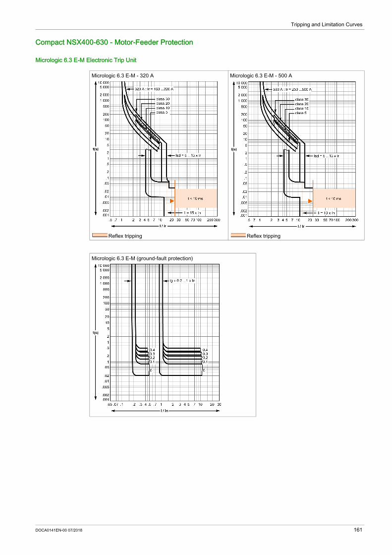
Tripping and Limitation Curves
Compact NSX400-630 - Motor-Feeder Protection
Micrologic 6.3 E-M Electronic Trip Unit
Micrologic 6.3 E-M - 320 A
Reflex tripping
Micrologic 6.3 E-M - 500 A
Reflex tripping
Micrologic 6.3 E-M (ground-fault protection)
DOCA0141EN-00 07/2018 161

Tripping and Limitation Curves
Compact NSX100-630 - Reflex Tripping
PresentationCompact NSX devices incorporate the exclusive reflex-tripping system.This system breaks very high fault currents.The device is mechanically tripped via a “piston” actuated directly by the short-circuit.For high short-circuits, this system provides a faster break, thereby ensuring selectivity.Reflex-tripping curves are exclusively a function of the circuit breaker rating.
162 DOCA0141EN-00 07/2018

Tripping and Limitation Curves
Compact NSX100-630 - Limitation Curves
PresentationThe limiting capacity of a circuit breaker is its aptitude to let through a current, during a short-circuit, that is less than the prospective short-circuit current.
The exceptional limiting capacity of the Compact NSX range is due to the rotating double-break technique (very rapid natural repulsion of contacts and the appearance of 2 arc voltages in-series with a very steep wave front).
Ics = 100% IcuThe exceptional limiting capacity of the Compact NSX range greatly reduces the forces created by fault in devices.The result is a major increase breaking performance.In particular, the service breaking capacity Ics is equal to 100% of Icu.The Icu value, defined by standard IEC/EN 60947-2, is guaranteed by tests comprising the following steps: Break the three times consecutively a fault current equal to 100% of Icu Check that the device continues to function normally, that is: it conducts the rated current without abnormal temperature rise. protection functions perform within the limits specified by the standard. suitability for isolation is not impaired.
Longer Service Life of Electrical InstallationsCurrent-limiting circuit breakers greatly reduce the negative effects of short-circuits on installations. Thermal effects:
Less temperature rise in conductors, therefore longer services life for cables. Mechanical effects:
Reduces electrodynamic forces, therefore less risk of electrical contacts, or busbar being deformed or broken.
Electromagnetic effects:Fewer disturbances for measuring devices located near electric circuits.
Economy by Means of CascadingCascading is a technique directly derived from current limiting. Circuit breaker with breaking capacities less than the prospective short-circuit current may be installed downstream of a limiting circuit breaker. The breaking capacity is reinforced by the limiting capacity of the upstream device. It follows that substantial savings can be mode on downstream equipment and enclosures.
DOCA0141EN-00 07/2018 163

Tripping and Limitation Curves
Current and Energy Limiting CurvesThe limiting capacity of a circuit breaker is expressed by two curves which are a function of the prospective short-circuit current (the current which would flow if no protection devices were installed): The actual peak current (limited current) Thermal stress (A²s), that is, the energy dissipated by the short-circuit in a condition with a resistance
of 1 Ω.Example:What is the real value of a 150 kA rms prospective short-circuit (that is, 330 kA peak) limited by an NSX250L upstream?The answer is 30 kA peak (see page 164).
Maximum Permissible Cable StressesThe following table indicates the maximum permissible thermal stresses for cables depending on their insulation, conductor (Cu or Al), and their cross-sectional area (CSA). CSA values are given in mm² and thermal stresses in A²s.
Example:Is a Cu/PVC cable with a CSA of 10 mm² adequately protected by an NSX160F? The table above indicates that the permissible stress is 1.32x10⁶ A2s.All short-circuit currents at the point where an NSX160F (Icu = 35 kA) is installed are limited with a thermal stress less than 6x10⁵ A2s (see page 165).Cable protection is therefore ensured up to the limit of the breaking capacity of the circuit breaker.
Current-limiting Curves
CSA Conductor 1.5 mm² 2.5 mm² 4 mm² 6 mm² 10 mm²PVC Cu 2.97x10⁴ 8.26x10⁴ 2.12x10⁵ 4.76x10⁵ 1.32x10⁶
Al – – – – 5.41x10⁵
PRC Cu 4.1x10⁴ 1.39x10⁵ 2.92x10⁵ 6.56x10⁵ 1.82x10⁶
Al – – – – 7.52x10⁵
CSA Conductor 16 mm² 25 mm² 35 mm² 50 mm²PVC Cu 3.4x10⁶ 8.26x10⁶ 1.62x10⁷ 3.31x10⁷
Al 1.39x10⁶ 3.38x10⁶ 6.64x10⁶ 1.35x10⁷
PRC Cu 4.69x10⁶ 1.39x10⁷ 2.23x10⁷ 4.56x10⁷
Al 1.93x10⁶ 4.7x10⁶ 9.23x10⁶ 1.88x10⁷
Voltage 400/440 Vac Voltage 660/690 VacLimited short-circuit current (k peak) Limited short-circuit current (k peak)
164 DOCA0141EN-00 07/2018

Tripping and Limitation Curves
Energy-limiting Curves
Voltage 400/440 Vac Voltage 660/690 VacLimited energy Limited energy
DOCA0141EN-00 07/2018 165


As standards, specifications and designs change from time to time, please ask for confirmationof the information given in this publication.
DOCA0141EN-00
Schneider Electric Industries SAS35, rue Joseph MonierCS30323F - 92506 Rueil Malmaison Cedex
http://www.schneider-electric.com 07/2018