Embed Size (px)
Citation preview

COMPACT MOSFET MODELSFOR VLSI DESIGN
A.B. BhattacharyyaJaypee Institute of Information Technology UniversityIndia


COMPACT MOSFET MODELSFOR VLSI DESIGN


COMPACT MOSFET MODELSFOR VLSI DESIGN
A.B. BhattacharyyaJaypee Institute of Information Technology UniversityIndia

Copyright © 2009 John Wiley & Sons (Asia) Pte Ltd, 2 Clementi Loop, # 02-01,Singapore 129809
Visit our Home Page on www.wiley.com
All Rights Reserved. No part of this publication may be reproduced, stored in a retrieval system or transmitted in anyform or by any means, electronic, mechanical, photocopying, recording, scanning, or otherwise, except as expresslypermitted by law, without either the prior written permission of the Publisher, or authorization through payment ofthe appropriate photocopy fee to the Copyright Clearance Center. Requests for permission should be addressed tothe Publisher, John Wiley & Sons (Asia) Pte Ltd, 2 Clementi Loop, #02-01, Singapore 129809, tel: 65-64632400,fax: 65-64646912, email: [email protected]
Designations used by companies to distinguish their products are often claimed as trademarks. All brand names andproduct names used in this book are trade names, service marks, trademarks or registered trademarks of theirrespective owners. The Publisher is not associated with any product or vendor mentioned in this book. Alltrademarks referred to in the text of this publication are the property of their respective owners.
This publication is designed to provide accurate and authoritative information in regard to the subject mattercovered. It is sold on the understanding that the Publisher is not engaged in rendering professional services. Ifprofessional advice or other expert assistance is required, the services of a competent professional should be sought.
Other Wiley Editorial Offices
John Wiley & Sons, Ltd, The Atrium, Southern Gate, Chichester, West Sussex, PO19 8SQ, UK
John Wiley & Sons Inc., 111 River Street, Hoboken, NJ 07030, USA
Jossey-Bass, 989 Market Street, San Francisco, CA 94103-1741, USA
Wiley-VCH Verlag GmbH, Boschstrasse 12, D-69469 Weinheim, Germany
John Wiley & Sons Australia Ltd, 42 McDougall Street, Milton, Queensland 4064, Australia
John Wiley & Sons Canada Ltd, 5353 Dundas Street West, Suite 400, Toronto, ONT, M9B 6H8, Canada
Wiley also publishes its books in a variety of electronic formats. Some content that appears in print may not beavailable in electronic books.
Library of Congress Cataloging-in-Publication DataBhattacharyya, A. B. (Amalendu Bhushan)
Compact MOSFET models for VLSI design / A.B. Bhattacharyya.p. cm.
Includes bibliographical references and index.ISBN 978-0-470-82342-2 (cloth)
1. Integrated circuits–Very large scale integration–Design and construction. 2. Metal oxide semiconductorfield-effect transistors–Design and construction. I. Title.
TK7874.75.B52 2009621.39’5–dc22
2008045585
ISBN 978-0-470-82342-2 (HB)
Typeset in 10/12pt Times by Thomson Digital, Noida, India.Printed and bound in Singapore by Markono Print Media Pte Ltd, Singapore.This book is printed on acid-free paper responsibly manufactured from sustainable forestry in which at least twotrees are planted for each one used for paper production.

Dedication
To my parents to whom I promised in my childhood that I would write a book.
To my wife Pranati, daughters Usree and Urmi, and family members Arun, Isha and Bela,for their selfless sacrifice and support, which allowed me to honor the most sacred of allobligations—the promise to my parents.


Contents
Preface xiii
Acknowledgements xvii
List of Symbols xxi
1 Semiconductor Physics Review for MOSFET Modeling 11.1 Introduction 11.2 Crystal Planes 41.3 Band Theory of Semiconductors 5
1.3.1 Energy–Momentum Relation and Energy Band Diagram 91.4 Carrier Statistics 14
1.4.1 Density of Energy States 141.4.2 Probability of Occupation of Energy States 151.4.3 Carrier Concentration for Non-degenerate Silicon 151.4.4 Degenerate Silicon and Band Gap Narrowing 171.4.5 Fermi Level Position 181.4.6 Quasi-Fermi Level 20
1.5 Carrier Generation and Recombination 211.5.1 Shockley–Read–Hall (SRH) Model 21
1.6 Carrier Scattering 231.6.1 Lattice Vibration Scattering 241.6.2 Ionized Impurity Scattering 251.6.3 Carrier–Carrier Scattering 251.6.4 Multiple-Scattering: Mathiessen’s Rule 251.6.5 Drift Velocity–Electric Field Characteristics 27
1.7 Contacts and Interfaces 291.8 Strained Silicon 31
1.8.1 Mobility Enhancement 321.9 Basic Semiconductor Equations 33
1.9.1 Poisson’s Equation 331.9.2 Current Density Equation 341.9.3 Current Continuity Equation 35

viii Contents
1.10 Compact MOSFET Models 361.11 The p–n Junction Diode 38
1.11.1 Transition Region 381.11.2 Recombination/Generation Current 401.11.3 Carrier Multiplication 421.11.4 SPICE Model Parameters for a p–n Junction Diode 43
1.12 Tunneling Through Potential Barrier 44References 48
2 Ideal Metal Oxide Semiconductor Capacitor 552.1 Physical Structure and Energy Band Diagram 552.2 Modes of Operation of MOS Capacitors 56
2.2.1 Volume Space Charge Density 572.2.2 Surface Space Charge Density 602.2.3 Surface Inversion Charge Density 632.2.4 Moderate Inversion 66
2.3 Electric Field and Potential Distributions 672.3.1 Distribution in Oxide 672.3.2 Distribution in Space Charge Region 68
2.4 Potential Balance 712.4.1 An Explicit Relation of φs with VGB 732.4.2 Slope Factor (n) 76
2.5 Inversion Layer Thickness 772.6 Threshold Voltage 79
2.6.1 Inversion Charge Density Above and Below the Threshold 812.6.2 Graphical Representation of Threshold Voltage 84
2.7 Small Signal Capacitance 862.7.1 Regional Approximations 88
2.8 Three Terminal Ideal MOS Structures 922.8.1 Cross-Section and Band Diagram 932.8.2 Space Charge Density, Surface Potential
and Threshold Voltage 942.8.3 Pinch-off Voltage 1012.8.4 Inversion Charge Density in Terms of VP and VSB 1042.8.5 Small Signal Capacitor Model 108
References 109
3 Non-ideal and Non-classical MOS Capacitors 1133.1 Introduction 1133.2 Flat-Band Voltage 114
3.2.1 Gate Substrate Work Function Difference φg /= φSi 1143.2.2 Oxide Charges 117

Contents ix
3.3 Inhomogeneous Substrate 1203.3.1 Types of Implant 1213.3.2 Pinch-off Voltage for an Inhomogeneous Substrate 1273.3.3 Vertical Substrate Inhomogeneity in Compact Models 129
3.4 Polysilicon Depletion Effect 1323.4.1 Effect on Threshold Voltage 1333.4.2 Inversion Charge with Polydepletion Effect 1363.4.3 Effect on C–V Characteristics 1373.4.4 Polydepletion Effect in Compact Models 139
3.5 Non-classical MOS Structures 1413.5.1 Threshold Voltages for Si–SiGe–Si MOS Heterostructures 1423.5.2 Si–SiGe–Si MOS Heterostructure 1433.5.3 Undoped Silicon 146
3.6 MOS Capacitor With Stacked Gate 1503.6.1 Thin Gate Oxide and Tunneling 1513.6.2 High-k Dielectric and Stacked Gate 151
References 153
4 Long Channel MOS Transistor 1594.1 Introduction 1594.2 Layout and Cross-Section of Physical Structure 1624.3 Static Drain Current Model 163
4.3.1 Gradual Channel Approximation 1654.3.2 Continuity Equation 1664.3.3 Transport Equation 1674.3.4 Pao–Sah Exact Model 1684.3.5 MOSFET Modeling Approaches for Circuit Simulation 1694.3.6 Charge Sheet Approximation 172
4.4 Threshold Voltage (VT ) Based Model 1774.4.1 Strong Inversion 1774.4.2 Smoothing Function for Piecewise Current Models in Strong Inversion 1834.4.3 Subthreshold or Weak Inversion Region 1844.4.4 Subthreshold Slope 185
4.5 Memelink–Wallinga Graphical Model 1864.5.1 Drain Current Saturation 1874.5.2 Geometrical Interpretation 188
4.6 Channel Length Modulation 1904.6.1 Early Voltage 192
4.7 Channel Potential and Field Distribution Along Channel 1934.8 Carrier Transit Time 1964.9 EKV Drain Current Model 197
4.9.1 Drain Current Interpolation 1984.9.2 Drain to Source Saturation Voltage 200
4.10 ACM and BSIM5 Models 202

x Contents
4.11 PSP Model 2044.11.1 Symmetric Bulk and Inversion Charge Linearization 204
4.12 HiSIM (Hiroshima University STARC IGFET Model) Model 2064.13 Benchmark Tests for Compact DC Models 208References 209
5 The Scaled MOS Transistor 2155.1 Introduction 2155.2 Classical Scaling Laws 216
5.2.1 Constant Field (CF) Scaling 2175.2.2 Constant Voltage (CV) Scaling 2175.2.3 Quasi-Constant Voltage (QCV) Scaling 2175.2.4 Generalized Scaling (GS) 2175.2.5 Flexible Empirical Scaling 217
5.3 Lateral Field Gradient 2215.3.1 Effect on Threshold Voltage 2225.3.2 Barrier Lowering Model 2235.3.3 Charge Sharing Model 2285.3.4 VT Implementation in Compact Models 234
5.4 Narrow and Inverse Width Effects 2375.4.1 Scaling Effect on Pinch-off Voltage 241
5.5 Reverse Short Channel Effect 2435.5.1 Arora’s Model 2435.5.2 BSIM3v3 Model 2455.5.3 EKVv2.6 Model 2465.5.4 HiSIM Model 246
5.6 Carrier Mobility Reduction 2485.6.1 Mobility Dependence on Gate Field 2495.6.2 Lateral Field Dependent Mobility 2535.6.3 Drain Current Modeling with Velocity Saturation 254
5.7 Velocity Overshoot 2605.8 Channel Length Modulation: A Pseudo-2-D Analysis 262
5.8.1 BSIM Model 2655.8.2 HiSIM Model 266
5.9 Series Resistance Effect on Drain Current 2675.9.1 PSP Model with Series Resistance Effect 270
5.10 Polydepletion Effect on Drain Current 2715.11 Impact Ionization in High Field Region 273
5.11.1 Substrate Current Model 2745.12 Channel Punch-Through 2775.13 Empirical Alpha Power MOSFET Model 277
5.13.1 Physical Interpretation of the Alpha Power Model 279References 281

Contents xi
6 Quasistatic, Non-quasistatic, and Noise Models 2896.1 Introduction 2896.2 Quasistatic Approximation 2916.3 Terminal Charge Evaluation 293
6.3.1 PSP Model 2936.3.2 EKV Model 2956.3.3 BSIM Model 2986.3.4 Terminal Charge in Accumulation Region 301
6.4 Quasistatic Intrinsic Small Signal Model 3016.4.1 Small Signal Conductances 3016.4.2 Transconductances (gmg and gms) 3036.4.3 Drain Conductance gmd 3046.4.4 Small Signal Capacitances 3056.4.5 Equivalent Circuit Model 3076.4.6 Medium Frequency Capacitance Model 3106.4.7 EKV Capacitance Model 3116.4.8 Meyer’s Simplified Capacitance Model 312
6.5 Extrinsic Capacitances 3126.5.1 Junction Capacitance 3136.5.2 Overlap Capacitances 315
6.6 Non-quasistatic (NQS) Models 3176.6.1 Non-quasistatic Large Signal Models 3176.6.2 Non-quasistatic Small Signal Models 321
6.7 Noise Models 3246.7.1 Analytical Channel Thermal Noise Model for MOSFETs
with Velocity Saturation 3306.7.2 Compact Thermal and Flicker Noise Models 3326.7.3 Induced Gate Noise 335
References 335
7 Quantum Phenomena in MOS Transistors 3397.1 Introduction 3397.2 Carrier Energy Quantization in MOS Capacitor 3407.3 2-D Density of States 3437.4 Electron Concentration Distribution 346
7.4.1 Self-consistent Results 3477.5 Approximate Methods 351
7.5.1 Triangular Well Approximation Method 3517.5.2 Variational Method 351
7.6 Quantization Correction in Compact MOSFET Models 3527.6.1 Threshold Voltage Model 3527.6.2 Effective Oxide Thickness 3547.6.3 HiSIM Model 3557.6.4 Philips MM11 and PSP Model 3557.6.5 EKV Model 356
7.7 Quantum Tunneling 358

xii Contents
7.8 Gate Current Density 3597.8.1 The Tsu–Esaki Model 3607.8.2 Tunneling Probability 3637.8.3 Gate Current and its Partition 364
7.9 Compact Gate Current Models 3657.9.1 BSIM4 Model 3677.9.2 PSP Model 3717.9.3 HiSIM Model 373
7.10 Gate Induced Drain Leakage (GIDL) 3737.10.1 Energy Band Bending at the Si–SiO2 Interface 3747.10.2 Analytical Expression for GIDL Current 377
References 379
8 Non-classical MOSFET Structures 3838.1 Introduction 3838.2 Non-classical MOSFET Structures 386
8.2.1 Single Gate UTB MOSFET on SOI 3868.2.2 Double Gate MOSFETs 3868.2.3 Nonplanar MOSFET Structures 3888.2.4 Strained-Silicon Structure 389
8.3 Double Gate MOSFET Models 3908.3.1 Electrostatic Potential 3918.3.2 Drain Current Models 3968.3.3 Short Channel Effect (SCE) 4048.3.4 Quantum Confinement Effect 4088.3.5 Compact DG MOSFET Models 410
References 412
Appendix A: Expression for Electric Field and Potential Variationin the Semiconductor Space Charge under the Gate 415
Appendix B: Features of Select Compact MOSFET Models 419
Appendix C: PSP Two-point Collocation Method 421
Index 427

Preface
The microelectronics industry has witnessed an explosive progress in the capability to integratecomponents on a silicon chip with CMOS as the predominant technology. The present daySystem-on-Chip (SOC) contains billions of devices with the Metal–Oxide–Semiconductor(MOS) transistor forming the basic building block. The successful design of such a complexintegrated system requires extensive computer simulation where an accurate and faithful mathe-matical description of the MOS transistor is an essential prerequisite. MOS characteristics,therefore, are described by a set of mathematical equations producing a compact model forthe device. These models are ported into a SPICE circuit simulator for faithful representationof MOSFET characteristics. Models provide the communicating interface between design andmanufacturing.
As the complexity and application domains of silicon chips continue to enlarge, the chal-lenge to satisfy apparently conflicting conditions of precision and simplicity is demandingand formidable. The litmus test of a compact model describing the MOS transistor lies in itscapability to describe the device characteristics in a way that it is computationally efficientand reliable to handle simulation of ever increasing complex circuits of an electronic systemensuring cost effectiveness and fast turn around time. Further, the model needs to be scal-able, predictive for the generations of technology nodes to follow, and capable of addressingstatistical process variations. With such multidimensional requirements, different approacheshave emerged which can be broadly categorized as Engineering models, Physical models, andApplication Specific hybrid models.
Historically, development of the threshold voltage, VT , based compact MOSFET modelwas pioneered by the University of California, Berkeley (UCB) and placed in the publicdomain. MOSIS (MOS Implementation Service) provides to the customers parameters forUCB models for a specified technology. The pedagogical approach, interfacing design withtechnology, has consequently been exclusively through VT based models. However, there havebeen developments in recent years which have led to a paradigm shift. Apart from the thresholdvoltage based method, new approaches using inversion charge and surface potential as statevariables have emerged, providing a new perspective in the field of compact models. PSP isalready recognized as an alternative standard for the compact MOSFET model.
The measured characteristics reflecting various phenomena related to the device is the ulti-mate physical reality as far as users are concerned. The perceived model representations for thesame phenomena, however, may be altogether different depending on the framework on whichthe model is structured. In the VLSI community, technologists use the model parameters toproject the most optimistic limit of the MOSFET performance, making parameter extractionas important as model development. Designers, on the other hand, judge the model parameters

xiv Preface
from the perspective of technological details revealed, and their compliance to simulationrequirements such as convergence, etc.
Scaling of feature size of MOSFETs is associated with ever increasing number of modelparameters. Thus, VLSI designers are confronted with a complex situation which forces themto handle a large number of parameters for a given model. Further, they need to make a judiciouschoice from a multiplicity of competing models. The formation of the Compact Model Council(CMC), more of an industry response, has been a natural and inevitable development forproviding benchmarks and standards for compact models. As there is very little possibility thata single model will be able to meet the requirements of a wide range of application domains,the diversity of models has to be accepted as a reality. Thus, VLSI designers need to be betterinformed and broadly educated with inclusive coverage of various compact MOSFET models,as against the prevailing practice of training on a specific or an exclusive model. However, theemerging pattern in the field of the compact MOSFET model rarely gets reflected in VLSIeducation in undergraduate and postgraduate courses. On the other hand, cutting edge insightsof new perceptions can stimulate the students and model users to a deeper understanding ofthe models. This will lead to a class of educated model consumers capable of exploiting themodels judiciously.
The objective of the author is to create awareness regarding the different approaches prevalentin compact MOSFET modeling in a single text at an introductory level. The present text is theoutcome of a project initiated by the author over the last six years in organizing broad-basedcourses on compact MOSFET models supporting VLSI design at both the undergraduate andpostgraduate levels. Selected topics from the material given in this text have also formed thebasis for customized modular courses on VLSI design for industry professionals. The authorreceived encouragement from both the academic and industry communities for preparing atext that highlights the core concepts of different models, which can prepare the foundationfor further model-specific specialization.
The text has been organized in such a way that it is self-contained. It summarizes in Chapter 1the basic equations of semiconductor physics necessary for understanding phenomena relatedto MOS transistors. Chapter 2 deals with an ideal MOS capacitor structure, where the basicconcepts and equations that are required to understand various compact models are developed.In Chapter 3 non-ideal effects, which are an integral part of real world practical MOS structures,are considered as add-on phenomena or perturbations over the ideal structure. Keeping in viewthe fact that the ITRS projected scaled MOSFET performance targets require intervention ofnon-classical structures, the basic MOS capacitor platform has been discussed with potentialgate and channel engineering alternatives requiring the use of an Si–Ge heterostructure andundoped silicon as the substrate, and the use of a high-k dielectric as a replacement of thesilicon–dioxide gate dielectric. Chapter 4 presents the formulation of four types of compactmodels, namely, VT based models, charge based models, and two surface-potential basedmodels. Chapter 5 deals with the effects of scaling on MOS transistor characteristics, anddiscusses how such phenomena are integrated into the various compact models. Chapter 6presents dynamic MOSFET models in quasistatic and non-quasistatic conditions outliningapproaches of the BSIM, EKV, HiSIM, and PSP models. The noise model has also beenpresented briefly. Quantum mechanical effects in nanoscale-MOSFETs have been outlined inChapter 7. The final chapter is on emerging non-classical structures which hold the prospectto replace mainstream conventional bulk CMOS structures. The basic equations for a doublegate MOSFET, which is projected to spearhead nanoscale CMOS, are derived.

Preface xv
There is modularity in the organization of the chapters which enables the reader to beselective. The field trials carried out by the author for undergraduate and postgraduate coursesare as follows: at both undergraduate and postgraduate levels the materials which are genericare discussed as core material. For undergraduates, the course was not for beginners but forthose who opted for the course on compact MOSFET models as an elective for specializing inVLSI design. The core material prepares the platform on which any particular model can belaunched. At the undergraduate level, the author experimented with threshold voltage basedmodels for classroom teaching, using the EKV approach for assignments. PSP/HiSIM wasreferred only qualitatively. The non-classical structures, quantum effects, and non-quasistaticmodels were not part of curriculum. At the postgraduate level, threshold voltage based modelsformed the classroom teaching material, and PSP/HiSIM constituted the assignment activity.EKV was referred qualitatively. The non-classical MOSFET structure, non-quasistatic effect,quantum phenomena and noise form the core material at the postgraduate level. Modularityin the presentation of topics, built in the text, allows flexibility to the instructor to mix andmatch the content with the requirement of the course. Proficiency in the use of a ComputerAlgebra System (CAS) is helpful, as compact model equations can be simulated. Such activitycan form an important component of assignments.
As more than one category of compact models have been presented in the text, it has beenimpractical to impose a common list of symbols globally. This would have required mod-ifications to all compact model equations with symbols that differ from those given in thecorresponding model documentation. As readers are expected to turn to the official docu-mentation of a specific compact model for details, such a change in symbols would createunnecessary confusion. Hence, a set of generic symbols, which relate to core material onMOS physics independent of model framework specifics, has been identified. The symbols ofspecific models, by and large, have been kept intact, and have been defined locally whereverused.
The book discusses model equations for highlighting the conceptual framework, and selectsthem based on suitability from a pedagogical viewpoint. Therefore, equations for the latestversion have not necessarily been considered to be the most suitable for introducing a model.At times, an earlier version happens to be a more convenient entry point to the model. Theselection of model equations in the text has to be viewed from this perspective. The frameworkof each class of model being different, the emphasis of the author has been to get the readersinitiated to the core concepts that form the basis of an approach, rather than on evolutionaryimprovements in a given approach. The text is neither a handbook, nor a replacement tothe official documentation available for each category of models. Further, as the models areregularly upgraded, the model equations used in the book do not necessarily reflect the currentstatus of a model. For some models information was sketchy and restricted. At many places,the text has used equations suitably truncated to serve the limited objective of pedagogy.Therefore, the readers are again advised to refer to the official documentation for the selectedmodel.
In the presentation of models the author has taken the position to be non-judgmental onthe merits, suitability, or otherwise, of a given model, leaving the reader to draw his/her ownconclusions. The extent of coverage of a given model, at times, has been dictated by theavailability of materials rather than assignment of any planned weightage on the coverage.
The text will be supported by a solution manual for instructors, which will be availablefrom the publisher’s website for the book. The simulation plots given in the text have mostly

xvi Preface
been implemented using MATLAB. The source code for these simulations shall also bemade available. These important and useful supplements can be found at the following URL:http://www.wiley.com/go/bhattacharyya.
It is believed that the broad pedagogical presentation of various models will bring them out ofthe captive domain of the few select industries using them for design and product development.Increased awareness regarding the various compact models available will hopefully lead towider participation in benchmarking the performance and evaluation of the models. The authorbelieves that such widespread participation from universities, through courses on compactmodels, will culminate in foundries providing model parameters for all categories of models.This will allow VLSI designers to make optimal use of the possibilities provided by the diversityof compact models.
A. B. BhattacharyyaNoida, Uttar PradeshIndia

Acknowledgements
I express my gratitude for the grace and blessings I received from my mentors, academic andspiritual, but for whom I could not have overcome many insurmountable roadblocks whichcame on the way since the project of writing a book on compact models for VLSI design waslaunched at the University of Goa, about five years ago. Prof. B. S. Sonde and Prof. P. R. Sar-ode provided the initial support. The author initiated an academic program where the compactMOSFET model, albeit in a small way, formed the nucleus of the concept of bringing dif-ferent categories of MOSFET models as a part of the curriculum. At a later stage, MOSFETcompact model related topics formed the course content at the Jaypee Institute of InformationTechnology University (JIITU), NOIDA (India), both at the undergraduate and the postgradu-ate level. The author records his appreciation for Gajanan Dessai, for useful interaction as astudent, having participated in model related courses delivered by the author both at Goa Uni-versity and at JIITU. His involvement later transcended beyond the classroom assignments.His contribution in Chapter 7 is specially acknowledged. He was also associated with theimplementation of simulations for the text and the solution manual. The following studentsof JIITU made supporting contributions for the solution manual: Umang Sah, Parul Gupta,Ankur Srivastava, Yashshri Negi, Kirminder Singh, Saurabh Chaturvedi, Nishant Chandra,and Apoorva Yati. No less has been the influence of my doctoral, postgraduate, and under-graduate students whose enthusiasm has been responsible for my remaining abreast with thecurrent state of developments in microelectronics. Prof. M. S. Tyagi provided useful editorialsuggestions for Chapter 1. The timely help from Dr Manoj Saxena, University of Delhi, for hiscontributions and review on MOSFET noise, is thankfully acknowledged. Rohit Sharma as-sisted the author in checking the manuscript of a few chapters. Usree Bhattacharya contributedsignificantly in arranging reference materials which was immensely useful. Urmi Battu offeredher bit in helping me with the illustrations.
The author is grateful to Prof. C. Hu, University of California, Berkeley, Prof. G. Gildenblat,Arizona State University, and Prof. C. Enz, CSEM and EPFL, Switzerland, for granting per-mission to use equations as necessary for the BSIM, PSP, and EKV models which they have re-spectively pioneered. Supporting material received from Prof. M. Miura-Mattausch on HiSIMis also appreciated. The permission from Prof. D. Vasilevska of Arizona State University, andProf. S. Banerjee of University of Texas, Austin, for using SCHRED and UTQUANT simulatorsis gratefully acknowledged. Prof. H. Wallinga, of the University of Twente, The Netherlands,favored the author with his lecture notes on the Memelink–Wallinga model. Prof. Ed Kinnen,the University of Rochester (NY), and Prof. R. Bowman, presently with the Rochester Insti-tute of Technology, Rochester (NY), are remembered for suggesting the need of a textbook

xviii Acknowledgements
relating MOSFET models with VLSI design, when the author was with them on a sabbatical.Prof. Kinnen’s practical suggestions regarding how not to get lost in the expanding MOSuniverse, and his abiding interest in the project, have been extremely refreshing.
The works of the authors of various compact modeling groups have been referred to fre-quently, as their models have been the subject of discussion. The book, however, has been noless influenced by the work of Prof. C. T. Sah, Prof. J. R. Brews, and Prof. Y. Tsividis. Theauthor is apologetic about the fact that many deserving works might not have been referred to.
The author records his deep appreciation for the sustained support of Prof. Suneet Tuli, IndianInstitute of Technology, Delhi, and Prof. D. N. Singh, University of Punjab, Chandigarh, onmaking available supporting technical literature. The constructive suggestions of unknownreviewers were responsible for the inclusion of some enriching content not originally plannedin the book.
It has been a pleasure to work with James Murphy and Roger Bullen, of John Wiley & Sons,Singapore, who pleasantly guided the author to successful compilation of the book.
I take this opportunity to express my sincere thanks to Dr Y. Meduri and Prof. J. P. Guptaof JIITU, who provided me the support and encouragement to complete the project. It was arewarding experience to interact with Prof. Sanjay Goel, Head, Computer Science Department,JIITU, Noida, in the planning of innovative learning centric and activity based approach forteaching compact models.
The author is conscious of omissions and the scope for improvement of the book. Suggestionsare welcome from readers.
Last but not the least, I have no adequate words to express my gratitude to my colleagueHarkesh Singh Dagar, but for whom perhaps the completion of the book would have everremained so near yet so far. Even though not belonging to the area of VLSI design, the projectbenefited enormously from his varied knowledge and experience spanning multiple scienceand engineering disciplines. His knowledge of digital typography also proved indispensable inthe preparation of the manuscript. Stimulating and objective discussions with him, free fromsubjective biases, led to a better appreciation of the limitations of the existing approaches tocompact modeling.
Further, he undertook the painful task of carrying out the review of the entire text and thesolution manual. His efforts have resulted in the ironing out of inconsistencies in the content,and simplified the presentation. He set up editorial discipline in the absence of which, in spiteof all technical content, the book would not have been anywhere near the level attained. Hisuncanny ability to uncover errors and inconsistencies has hopefully eliminated most blemishesat the pre-production stage. The author owns responsibility for any errors or omissions whichremain. I remain indebted to him forever for his selfless effort. I take this opportunity to thankhis family, and record my deep appreciation for their self-effacing support and sacrifice, whileHarkesh got involved with this project.

This is practice, but remember first to set forth the theory.
Leonardo da Vinci
John Wheeler was an advocate of doing more with less. That is how scientific modeling shouldbe done, rather than heaping on a bunch of parameters to match phenomena—a good modelaccomplishes more, explains more than what it contains.
Todd RowlandAcademic Director
NKS Summer SchoolWolfram Research, Inc.


List of Symbols
Physical Constants
ε0 = 8.854 × 10⁻¹⁴ F cm−1 Permittivity of free spaceεSi = 11.7ε0 Permittivity of Siεox = 3.97ε0 Permittivity of SiO2
q = 1.6 × 10⁻¹⁹ C Electron chargek = 1.38 × 10⁻²³ JK−1 Boltzmann’s constanth = 6.63 × 10⁻³⁴ J sec Planck’s constantm = 9.1 × 10⁻³¹ kg Free electron mass
Select Parameter Values for Silicon
m∗n = 0.33 (relative to unity) Effective mass of electron
m∗p = 0.55 (relative to unity) Effective mass of hole
Values at a temperature of300 K
ni = 1.4 × 1010 cm−3 Intrinsic carrier concentrationμn = 1400 cm2 V−1 s−1 Electron mobility in bulk siliconμp = 500 cm2 V−1 s−1 Hole mobility in bulk siliconvsat,n = 8.5 × 106 cm s−1 Saturation velocity for electronsvsat,p = 5.0 × 106 cm s−1 Saturation velocity for holesFc,n = 2.5 × 10³ V cm−1 Critical electric field for electron saturation velocityFc,p = 2.5 × 10³ V cm−1 Critical electric field for hole saturation velocity
Dimensions
LG Mask defined gate lengthL = LG − 2LD Channel lengthLD Length of lateral diffusion from source/drain under the gateLe Corrected channel length in saturationL(S, D) Length of source, drain diffusion region in the direction of
channelLb Debye length�L Length of pinched-off/high field region near drainLn Electron diffusion lengthLp Hole diffusion lengthl Mean free pathl Characteristic length (context dependent)W = Wg − 2DW Effective channel width

xxii List of Symbols
Wd Width of depletion regionWds Depletion width at sourceWdd Depletion region at sourceWdc Channel depletion widthWdm Maximum width of depletion region at thresholdWdps Depletion width in polysiliconWi Inversion layer thicknessWI Implant depthWE Equivalent depletion layer depth source/drainXj Source/drain junction depthTox Gate oxide thicknessTfox Field oxide thicknessa0 Lattice constant of siliconx Direction perpendicular to channely Direction parallel to channel
Doping and Carrier Concentrations
NB Bulk impurity doping volume concentrationND Donor impurity doping volume concentrationNA Acceptor impurity doping volume concentrationnn0 Electron concentration in n-type Si at thermal equilibriumpn0 Hole concentration in n-type Si at thermal equilibriumNP Polysilicon doping concentrationNc Effective density of states in conduction band (cm−3)Nv Effective density of states in valence band (cm−3)nn Non-equilibrium free electron density in n-type Sipp Non-equilibrium free hole density in p-type Sinp Non-equilibrium free electron density in p-type Sipn Non-equilibrium free hole density in n-type Sini Instrinsic carrier concentrationnie Effective instrinsic carrier concentrationn+ Highly doped n-regionNI Implant layer doping volume concentrationNE Equivalent transformed doping volume concentration for inhomo-
geneous substrate
Energy
E EnergyEc Lower edge of the conduction energy bandEcb Lower edge of the conduction band of the bulk (substrate) materialEcg Lower edge of the conduction band of the gate materialEv Upper edge of the valence energy bandEf Fermi energy levelEg Energy band gap (eV)�Eg Energy band gap narrowingχSi Electron affinity for Si (eV)Ei Intrinsic Fermi levelEd Donor energy levelEa Acceptor energy level

List of Symbols xxiii
Efg Fermi energy level of gate materialEfn Quasi-Fermi energy level for electronsEfp Quasi-Fermi energy level for holes
Voltages and Currents
φg Potential corresponding to work function of gate materialφSi Potential corresponding to work function of Siφ Electrostatic potentialφF Fermi potentialφf Bulk potential; the potential difference between Fermi and intrin-
sic energy levelφt Thermal voltage (= kT/q)φs Surface potential with reference to bulkφss Surface potential with reference to sourceφsS Surface potential at source end of the channelφsD Surface potential at drain end of the channel�b Conduction band offset between Si–SiO2
φbi Built-in potential barrier across junctionφgs Potential corresponding to work function difference between gate
and substrateφn Quasi-Fermi potential of electronsφp Potential drop across polysilicon depletion layerφsm Surface potential at midpoint of the channel (L/2)φ0 Surface potential at onset of strong inversion�φ0 Drain induced barrier lowering w.r.t. sourceφi Potential at high–low/low–high transition point in inhomogeneous
substrateVGB Gate voltage w.r.t. bulkVDB Drain voltage w.r.t. bulkVSB Source voltage w.r.t. bulkVox Voltage drop across gate oxideVDS Drain voltage w.r.t. sourceVGS Gate voltage w.r.t. sourceVCB Channel potential w.r.t. bulkVDG Drain to gate voltageVCS Channel potential w.r.t. sourceVfb Flat band voltageVT Threshold voltageVT0 Threshold voltage without substrate biasVTB Threshold voltage w.r.t. bulkVTS Threshold voltage w.r.t. sourceVMI Gate voltage corresponding to φs = 2φF
VWI Gate voltage corresponding to φs = φF
VSI Gate voltage corresponding to φs = (2φF + mφt)VDSsat Drain current saturation voltageVP Pinch-off voltageIDSsat Saturation drain currentIDS Drain to source currentI Current

xxiv List of Symbols
Idiff Diffusion currentIdrift Drift currentIDB Drain to bulk currentIsub Substrate current due to hot electronsIG Gate currentIGS Gate to source tunneling currentJ Current densityJn,diff Diffusion current density due to electronsJp,diff Diffusion current density due to holesJn,drift Drift current density due to electronsJp,drift Drift current density due to holesTC Tunneling coefficientS Supply function
Charges
Q′b Bulk charge density per unit area
Q′bm Maximum bulk charge density per unit area
Q′n Inversion layer charge density per unit area
Q′g Gate charge density per unit area
Q′sc Surface space charge density per unit area
Q′f Fixed oxide charge density per unit area in SiO2
Q′m Mobile charge density per unit area in SiO2
Q′it Interface trapped charge density per unit area
Q′ot Oxide trapped charge density per unit area
Qs Total inversion charge assigned to sourceQd Total inversion charge assigned to drainρ Volume space charge density per unit volume
Capacitances
C′ox Oxide capacitance per unit area
C′sc Space charge capacitance per unit area
C′b Depletion layer capacitance per unit area
C′n Inversion layer capacitance per unit area
C′eq Equivalent gate–substrate capacitance per unit area
C′min Minimum gate–bulk capacitance per unit area
C′dmin Minimum depletion capacitance per unit area
C′fb Flat band capacitance per unit area
Cdiff Diffusion capacitanceC′
j Junction capacitance per unit areaC′
j0 Zero bias junction capacitance per unit areaCgs Gate–source intrinsic capacitanceCgd Gate–drain intrinsic capacitanceCgb Gate–bulk intrinsic capacitanceCbs Bulk–source intrinsic capacitanceCbd Bulk–drain intrinsic capacitanceCox = C′
oxWL Total oxide capacitanceCov Total gate to source/drain capacitance
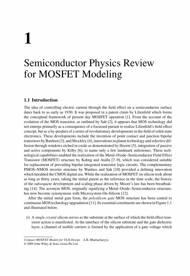
1Semiconductor Physics Reviewfor MOSFET Modeling
1.1 Introduction
The idea of controlling electric current through the field effect on a semiconductor surfacedates back to as early as 1930. It was proposed in a patent claim by Lilienfeld which formsthe conceptual framework of present day MOSFET operation [1]. From the account of theevolution of the MOS transistor, as outlined by Sah [2], it appears that MOS technology didnot emerge primarily as a consequence of a focussed pursuit to realize Lilienfeld’s field effectconcept, but as a by-product of a series of revolutionary developments in the field of solid-stateelectronics. These developments include the invention of point contact and junction bipolartransistors by Bardeen [3], and Shockley [4], innovations in planar technology and selective dif-fusion through windows etched in oxide as demonstrated by Hoerni [5], integration of passiveand active components by Kilby [6], to name only a few landmark milestones. These tech-nological capabilities enabled the realization of the Metal–Oxide–Semiconductor Field EffectTransistor (MOSFET) structure by Kahng and Atalla [7–9], which was considered suitablefor replacement of prevailing bipolar integrated transistor logic circuits. The complementaryPMOS–NMOS inverter structure by Wanlass and Sah [10] provided a defining innovationwhich heralded the CMOS digital era. While the realization of MOSFET on silicon took aboutas long as thirty years, taking the initial patent as the reference in the time scale, the historyof the subsequent development and scaling phase driven by Moore’s law has been breathtak-ing [14]. The acronym MOS, originally signifying a Metal–Oxide–Semiconductor structure,has now become synonymous with Microsystem-On-Silicon [12].
After the initial metal gate form, the polysilicon gate MOS structure has been central tocontinuous MOS technology upgradation [11]. Its essential constituents are shown in Figure 1.1and illustrated below.
(i) A single crystal silicon serves as the substrate at the surface of which the field effect tran-sistor action is manifested. At the interface of the silicon substrate and the gate dielectriclayer, a channel of mobile carriers is formed by the application of a gate voltage which
Compact MOSFET Models for VLSI Design A.B. Bhattacharyya© 2009 John Wiley & Sons (Asia) Pte Ltd

2 Compact MOSFET Models for VLSI Design
Polycrystalline Si
Crystalline substrate
Silicon contact
n+ n+ n+ n+
Silicon contactp-Si
GS DG
BB BB
(+VGB) (+VGS) (+VDS)
MO
(a) (b)
Amorphous SiO2
Figure 1.1 Components of the field effect transistor structure: (a) MOS capacitor and contacts; (b)composite MOSFET device
controls the conductivity of the channel. For the device to be reproducible and reliable, itis obligatory that the substrate material be a single crystal where atoms are arranged inan orderly array.
(ii) A silicon-dioxide layer is integrated with the substrate at the top of the silicon surfacewhich insulates the silicon substrate from the gate electrode. The insulating film is struc-turally amorphous where no perceivable long-range crystalline order exists.
(iii) Over the insulating dielectric a polysilicon film is deposited where a relatively smallsegment of the film has an ordered crystalline order. The poly-layer at the top serves asthe gate electrode, and is heavily doped to make its conductivity approach that of a metal.Though high conductivity polycrystalline silicon replaces the original metal electrode ontop of the gate oxide, it continues to be labelled as a metal as a historic continuity of thenomenclature of MOS for the device structure.
(iv) Finally, ohmic contacts are established with the polysilicon layer at the top and the siliconsubstrate at the bottom, for which aluminum has been the most commonly used material.The stack of the above three layers, with the top and bottom electrodes designated as Gateand Bulk terminals, respectively, provide the platform for Field Effect characteristics.
(v) The two terminal MOS capacitor described above, provides the platform to observe theField Effect phenomenon at the Si–SiO2 interface in the form of a gate controlled spacecharge constituted by mobile carriers and fixed bulk charges. The mobile carriers inducedat the silicon substrate under the gate at the interface are connected to the external worldthrough conducting silicon probes of the same conductivity as that of the mobile carriersin the channel. The external voltage applied at the two end terminals results in a currentwhich is controlled by the gate field. The basic four terminal MOSFET structure shownin Figure 1.1 is formed by integrating the diffusion contacts with the MOS capacitor ona common substrate. The capacitor under the gate forms the intrinsic part of the MOStransistor, whereas the contact terminals form the extrinsic part of the device.
MOS technology has undergone unprecedented evolution to keep pace with projection onscaling as envisaged by Gordon Moore [14]. Unlike the pre-birth history of the MOS transis-tor, the future has been made almost predictive. The International Technology Roadmap for

Semiconductor Physics Review for MOSFET Modeling 3
Semiconductor (ITRS) lays down projections for a comprehensive development of MOS tech-nology which is indicative of the trends, tasks, challenges, and opportunities in the years aheadin terms of process integration, system development, materials, device architecture, bottle-necks, etc. The document is dynamically updated. Table 1.1 is an illustrative projection [13].
Table 1.1 ITRS 2003 roadmap for high-performance logic
Year 2003 2006 2009 2012 2015 2018
Technology node (nm) 100 70 50 35 25 18MPU gate length (nm) 45 28 20 14 10 7Vdd (V) 1.2 1.1 1.0 0.9 0.8 0.7Tox (A) 13 10 8 7 6 5Clock frequency (MHz) 2 976 6 783 12 369 20 065 33 403 53 207Maximum power (W) 149 180 210 240 270 300Static power (W/μm) 4.0 × 10⁻⁷ 6.1 × 10⁻⁷ 7.7 × 10⁻⁷ 9.9 × 10⁻⁷ 2.6 × 10⁻⁶ 3.9 × 10⁻⁶
Nominal gate delay (ps) 30.24 18.92 12.06 7.47 4.45 2.81Power delay product (J/μm) 1.4 × 10⁻¹⁵ 9.7 × 10⁻¹⁵ 7.7 × 10⁻¹⁶ 4.8 × 10⁻¹⁶ 3.0 × 10⁻¹⁶ 1.7 × 10⁻¹⁶
Transistors per chip (×106) 153 307 614 1227 2454 4908
Though the basic MOS structure remains the core of development forecast, the primitiveMetal–Oxide–Semiconductor has evolved into a significant complex structure which resemblesa stack of multiple layers of varying properties and increasing number of interfaces as shownin Figure 1.2 due to the requirements of gate, channel, and interface engineering.
.
Polysilicon layer
Interface layer-1 Gate dielectric
Interface layer-2
Conducting channel
Depletion layer
Si-substrate
G
B
Gate engineering
Channel engineering
Metal–poly contact
Metal–substrate contact
Figure 1.2 Stacked layers and interfaces in the evolving MOS structure

4 Compact MOSFET Models for VLSI Design
The channel engineering has resulted in substrate inhomogeneity, stratification, and hetero-geneity of material near the Si–SiO2 interface as shown by dashed lines. The gate engineeringhas lead to stacking of dielectric layers to avoid tunneling through the thin gate insulator. Thetransitions at the interfaces are not abrupt, introducing effectively transition layers with gradedmaterial composition. Thus, the device characteristics and modeling are closely linked with theproperties of the materials forming the layers. With miniaturization, the dimensions correspondto only a few atomic layers, where quantum effects start governing the device physics.
The inputs required for MOSFET modeling are: material properties, device structure anddimensions, process details, parameters related to carrier statistics, mobility, band gap narrow-ing, carrier recombination, generation and multiplication, quantization and tunnelling effects,etc. The present chapter provides a brief summary of the above aspects, more in the form ofstatements, for the purpose of ready reference without going to details which are available ina number of texts on the subject [17–22].
1.2 Crystal Planes
The crystal structure of silicon (Si) is diamond cubic type, where each atom makes covalentbonds with four neighboring atoms to form a tetrahedral structure. In a MOSFET, the devicecharacteristics depend on the crystal plane on which the device is fabricated. In a crystalstructure, the orientation of planes is defined by Miller indices, which are expressed by a set ofinteger numbers. The procedure to obtain Miller indices of a crystal plane is explained throughan illustration shown in Figure 1.3, where x, y, and z define the directions of the primitivevectors of the lattice.
� Step1: Find the intercept of the plane under consideration in terms of the axial units alongthe axes. In Figure 1.3 the intercepts are A, B, and C where A = 3, B = 2, and C = 2 units.
� Step2: Take reciprocals of the intercepts which, for the present case, are: 1/A, 1/B, and1/C, i.e. 1/3, 1/2, and 1/2 respectively.
� Step3: Get the common denominator D of the intercepts A, B, and C. Multiplying thereciprocal numbers by D we get the sets of numbers defining the Miller indices (h, k, l)where h = D/A, k = D/B, and l = D/C, i.e. (2, 3, 3) for the plane under consideration.
In case a plane is parallel to an axis, the intercept of the plane with the above axis is takenas infinity and the reciprocal of the intercept becomes 1/∞ = 0.
Figure 1.3 shows the (100) plane in a cubic crystal. The preferred orientation of the plane of asilicon crystal for fabrication of conventional MOS devices is (100) with SiO2 as the dielectric
(100)
xy
z
y
z
x
(3,0,0)(0,2,0)
(0,0,2)
Figure 1.3 Crystal plane representation in a lattice