Embed Size (px)
Citation preview

Communications Theory and Engineering
Master's Degree in Electronic Engineering
Sapienza University of Rome
A.A. 2020-2021

Multiple Access
TDMA, FDMA, CDMA

From the single link to the network
• In a digital communication network many users simultaneously communicate with one another
• A key issue is how to provide access to a single transmission medium for two or typically many more users

Domains of application
• Full-duplex transmission on a single medium: the two directions of transmission must share one medium such as a wire pair (example the digital subscriber loop for the telephone channel)
• Multiple communications over a common high-speed link, such as the optical fiber: this is called multiplexing
• Many users share a wireless channel and broadcast information: cellular communications, wireless local area networks, satellite networks

Multiple Access
• Multiple access refers in general to any situation where two or more users share a common transmission medium
• Messages corresponding to different users must be separated in some fashion
• They should not interfere with one another
• This is usually obtained by making the messages orthogonal to one another in the signal space

Messages separated in time
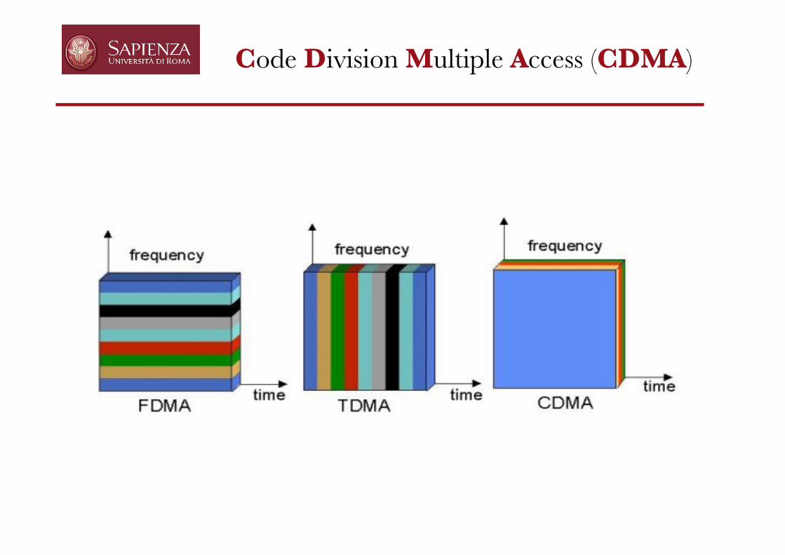
• In Time Division Multiple Access (TDMA) each user is allowed to transmit only within specified time intervals (Time Slots). Different users transmit in differents Time Slots
• When users transmit, they occupy the whole frequency band; separation among users is performed in the time domain

TDMA : Frame Structure
• TDMA requires a centralized control node, whose primary function is to transmit a periodic reference burst that defines a frame and forces a measure of synchronization of all users
• This frame is divided into Time Slots, and each user is assigned a Time Slot for transmitting information
TF
TS
Frame
Time Slot
Refe
renc
e Bu
rst

TDMA : Frame Structure
User 1 User 2 User 3

TDMA : guard intervals
• Since the distance between users and central unit may vary, users may receive the reference burst with different phases, and correspondingly transmit misaligned traffic bursts
• There is therefore a need for guard intervals to take into account this variability and avoid overlaps
• The Time Slot is therefore longer than strictly needed, thereby avoiding the overlap in presence of unknown propagation delays
misalignment misalignment
with guard time without guard time

TDMA : preamble
• Since traffic bursts are transmitted with uncertain phases relative to the reference burst, a preamble is needed at the beginning of each traffic burst
• The preamble allows the receiver to acquire, on top of coarse synchronization provided by the reference burst, a fine estimate of timing and carrier phase
preamble information

0 0.002 0.004 0.006 0.008 0.01 0.012 0.014
-100
-50
0
50
100
TIME [s]
AMPLITUDE [V]
0 0.002 0.004 0.006 0.008 0.01 0.012 0.014 0.016
-15
-10
-5
0
5
10
15
Time [s]
Amplitude [V]
sRX
j( ) t( )sTXj( ) t( )
Received signal afterpropagation over a two-paths channel
BEWARE!
At risk of multiuserinterference!
TDMA and channels with multipath

Frequency DivisionMultiple Access (FDMA)
• Each user transmits with no limitations in time, but using only a portion of the whole available frequency bandwidth.
• Users are separated in the frequency domain.
User 1
User 2
User 3
Time
Frequency
Power

FDMA vs. TDMA
• Frequency division is very simple: all transmitters sharing the medium have output power spectra in non-overlapping bands.– Many of the problems experienced in TDMA due to different
propagation delays are eliminated in FDMA
• A major disadvantage of FDMA is the need for expensive and sophisticated bandpass filters– TDMA is realized primarily with much cheaper logic functions
• Another disadvantage of FDMA is sensitivity towards channelnon-linearity

TDMA + FDMA
FDMA TDMA + FDMA
Frequency
Time Time
Frequency
Power
CarriersUsers
User 1
User 2
User 3
Power

TDMA + FDMA in the GSM900 standard
Code Division Multiple Access (CDMA)

CDMA and Spread Spectrum
• CDMA is based on a technique called spread-spectrum
• As its name indicates this technique consists in “spreading” the spectrum over the whole set of available frequencies
• All users transmit then over all frequencies but are separated from one another thanks to coding
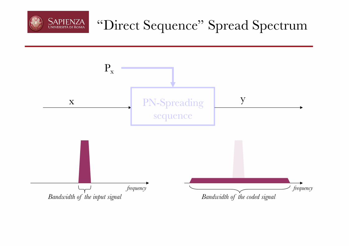
x yPN-Spreadingsequence
Px
frequencyBandwidth of the input signal Bandwidth of the coded signal
frequency
“Direct Sequence” Spread Spectrum

Original signal(band related to bit rate=1/Tb)
“Direct Sequence” Spread Spectrum
Tbbit time
Tcchip time
PN Sequence: 0110001001called “spreading sequence”

Original signal(band related to bit rate=1/Tb)
“Direct Sequence” Spread Spectrum
Tbbit time
PN Sequence: 0110001001called “spreading sequence”
Tcchip time

Original signal(band related to bit rate=1/Tb)
“Direct Sequence” Spread Spectrum
Tbbit time
Tcchip time
DSSS signal(band related to chip rate=1/Tc)
PN Sequence: 0110001001called “spreading sequence”

Signal 1 DSSS signal 1
“Direct Sequence” Spread Spectrum
XX
Integrator
- - + -0 0 1 0
0 0 1 0

The DS-CDMA coded signal
Digital binary signal
𝑠 ! 𝑡 = $"𝑎"! 𝑟𝑒𝑐𝑡# 𝑡 − 𝑘𝑇
𝑠!"#!$%& 𝑡 =$
'𝑎'& $()*
+!"
𝑝 & 𝑚 𝑟𝑒𝑐𝑡,# 𝑡 −𝑚𝑇# − 𝑘𝑇
DS-CDMA-coded signal
𝑟 ! 𝑡 = $"𝑎"! $$%&
'!"
𝑝 ! 𝑚 . 𝑝 ! 𝑚 . 𝑟𝑒𝑐𝑡## 𝑡 − 𝑚𝑇( − 𝑘𝑇
= $"𝑎"! 𝑟𝑒𝑐𝑡# 𝑡 − 𝑘𝑇 𝑎𝑠 (𝑝 ! 𝑚 . 𝑝 ! 𝑚 = 1)
𝑍" = ∫ 𝑎"! 𝑟𝑒𝑐𝑡# 𝑡
𝑟𝑒𝑐𝑡# 𝑡𝑇
𝑑𝑡 = 𝑎"(!)
Received signal after unspreading
Decision variable after correlator

The DS-CDMA coded signal
Digital binary signal
𝑠 ! 𝑡 = $"𝑎"! 𝑟𝑒𝑐𝑡# 𝑡 − 𝑘𝑇
𝑠!"#!$%& 𝑡 =$
'𝑎'& $()*
+!"
𝑝 & 𝑚 𝑟𝑒𝑐𝑡,# 𝑡 −𝑚𝑇# − 𝑘𝑇
DS-CDMA-coded signal
𝑟 ! 𝑡 = $"𝑎"! $$%&
'!"
𝑝 ! 𝑚 . 𝑝 ! 𝑚 . 𝑟𝑒𝑐𝑡## 𝑡 − 𝑚𝑇( − 𝑘𝑇
= $"𝑎"! 𝑟𝑒𝑐𝑡# 𝑡 − 𝑘𝑇 𝑎𝑠 (𝑝 ! 𝑚 . 𝑝 ! 𝑚 = 1)
𝑍" = ∫ 𝑎"! %$%&
'"#
𝑝 ! 𝑚 𝑟𝑒𝑐𝑡#$ 𝑡 − 𝑚𝑇( . %$%&
'"#
𝑝 ! 𝑚𝑟𝑒𝑐𝑡#$ 𝑡 − 𝑚𝑇(
𝑇𝑑𝑡 = 𝑎"
(!)
Received signal after unspreading
Decision variable after correlator:

The DS-CDMA coded signal
Digital binary signal
𝑠 ! 𝑡 = $"𝑎"! 𝑟𝑒𝑐𝑡# 𝑡 − 𝑘𝑇
𝑠!"#!$%& 𝑡 =$
'𝑎'& $()*
+!"
𝑝 & 𝑚 𝑟𝑒𝑐𝑡,# 𝑡 −𝑚𝑇# − 𝑘𝑇
DS-CDMA-coded signal
𝑟 ! 𝑡 = $"𝑎"! $$%&
'!"
𝑝 ! 𝑚 . 𝑝 ! 𝑚 . 𝑟𝑒𝑐𝑡## 𝑡 − 𝑚𝑇( − 𝑘𝑇
= $"𝑎"! 𝑟𝑒𝑐𝑡# 𝑡 − 𝑘𝑇 𝑎𝑠 (𝑝 ! 𝑚 . 𝑝 ! 𝑚 = 1)
𝑍' = ∫ 𝑠!"#!$%& 𝑡 + 𝑘𝑇 . $
()*
+!"
𝑝 & 𝑚𝑟𝑒𝑐𝑡,# 𝑡 −𝑚𝑇#
𝑇 𝑑𝑡 = 𝑎'(&)
Received signal after unspreading
Decision variable after correlator:

Sign
al1
Sign
al2
Codedsignal 1
Codedsignal 2
Adding codedsignals 1 and 2
“Direct Sequence” Spread Spectrum
PN Sequence: 0110001001
PN Sequence: 1111101100
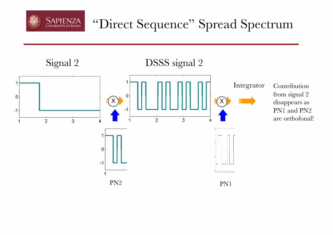
Signal 2 DSSS signal 2
“Direct Sequence” Spread Spectrum
XX
Integrator Contributionfrom signal 2 disappears asPN1 and PN2 are orthofonal!
PN2 PN1

“Direct Sequence” Spread Spectrum
Received signal 1+2
Spreading sequence used to encode signal 1
multiplier
Signal 2 removed
X
It works if codes are orthogonal!
Signal 1: 0 0 1 0 Integrator

The DS-CDMA coded signal
Digital binary signal
𝑠 ! 𝑡 = $"𝑎"! 𝑟𝑒𝑐𝑡# 𝑡 − 𝑘𝑇
𝑠!"#!$%& 𝑡 =$
'𝑎'& $()*
+!"
𝑝 & 𝑚 𝑟𝑒𝑐𝑡,# 𝑡 −𝑚𝑇# − 𝑘𝑇
DS-CDMA-coded signal
𝑟 ! 𝑡 = $"𝑎"! $$%&
'!"
𝑝 ! 𝑚 . 𝑝 ! 𝑚 . 𝑟𝑒𝑐𝑡## 𝑡 − 𝑚𝑇( − 𝑘𝑇
= $"𝑎"! 𝑟𝑒𝑐𝑡# 𝑡 − 𝑘𝑇 𝑎𝑠 (𝑝 ! 𝑚 . 𝑝 ! 𝑚 = 1)
𝑍" = ∫ 𝑎"! 𝑟𝑒𝑐𝑡# 𝑡
𝑟𝑒𝑐𝑡# 𝑡𝑇
𝑑𝑡 = 𝑎"(!)
Received signal after unspreading
Decision variable after correlator

The DS-CDMA coded signal
Digital binary signal
𝑠 ! 𝑡 = $"𝑎"! 𝑟𝑒𝑐𝑡# 𝑡 − 𝑘𝑇
𝑠!"#!$%& 𝑡 =$
'𝑎'& $()*
+!"
𝑝 & 𝑚 𝑟𝑒𝑐𝑡,# 𝑡 −𝑚𝑇# − 𝑘𝑇
DS-CDMA-coded signal
𝑟 ! 𝑡 = $"𝑎"! $$%&
'!"
𝑝 ! 𝑚 . 𝑝 ! 𝑚 . 𝑟𝑒𝑐𝑡## 𝑡 − 𝑚𝑇( − 𝑘𝑇
= $"𝑎"! 𝑟𝑒𝑐𝑡# 𝑡 − 𝑘𝑇 𝑎𝑠 (𝑝 ! 𝑚 . 𝑝 ! 𝑚 = 1)
𝑍" = ∫ 𝑎"! %$%&
'"#
𝑝 ! 𝑚 𝑟𝑒𝑐𝑡#$ 𝑡 − 𝑚𝑇( . %$%&
'"#
𝑝 ! 𝑚𝑟𝑒𝑐𝑡#$ 𝑡 − 𝑚𝑇(
𝑇𝑑𝑡 = 𝑎"
(!)
Received signal after unspreading
Decision variable after correlator:

The DS-CDMA coded signal
Digital binary signal
𝑠 ! 𝑡 = $"𝑎"! 𝑟𝑒𝑐𝑡# 𝑡 − 𝑘𝑇
𝑠!"#!$%& 𝑡 =$
'𝑎'& $()*
+!"
𝑝 & 𝑚 𝑟𝑒𝑐𝑡,# 𝑡 −𝑚𝑇# − 𝑘𝑇
DS-CDMA-coded signal
𝑟 ! 𝑡 = $"𝑎"! $$%&
'!"
𝑝 ! 𝑚 . 𝑝 ! 𝑚 . 𝑟𝑒𝑐𝑡## 𝑡 − 𝑚𝑇( − 𝑘𝑇
= $"𝑎"! 𝑟𝑒𝑐𝑡# 𝑡 − 𝑘𝑇 𝑎𝑠 (𝑝 ! 𝑚 . 𝑝 ! 𝑚 = 1)
𝑍' = ∫ 𝑠!"#!$%& 𝑡 + 𝑘𝑇 . $
()*
+!"
𝑝 & 𝑚𝑟𝑒𝑐𝑡,# 𝑡 −𝑚𝑇#
𝑇 𝑑𝑡 = 𝑎'(&)
Received signal after unspreading
Decision variable after correlator:

The DS-CDMA coded signal
If we have another signal(i)
𝑠 + 𝑡 = $"𝑎"+ 𝑟𝑒𝑐𝑡# 𝑡 − 𝑘𝑇
𝑠!"#!$%/ 𝑡 =$
'𝑎'/ $()*
+!"
𝑝 / 𝑚 𝑟𝑒𝑐𝑡,# 𝑡 −𝑚𝑇# − 𝑘𝑇
With another orthogonal spreadingsignal
𝑟 + 𝑡 = $"𝑎"+ $$%&
'!"
𝑝 + 𝑚 . 𝑝 ! 𝑚 . 𝑟𝑒𝑐𝑡## 𝑡 − 𝑚𝑇( − 𝑘𝑇
𝑍$% = ∫ 𝑎$% 4&'(
)!"
𝑝 % 𝑚 . 𝑝 * 𝑚 . 𝑟𝑒𝑐𝑡+# 𝑡 − 𝑚𝑇, .𝑟𝑒𝑐𝑡+ 𝑡
𝑇𝑑𝑡 = 𝑎$%
𝑇-𝑇4&'(
)!"
𝑝 % 𝑚 . 𝑝 * 𝑚 = 0
Passing through the receiver of signal j
Decision variable after correlator:
𝑝 +as and are orthogonal𝑝 !

The DS-CDMA coded signal
𝑠!"#!$%& 𝑡 + 𝑠!"#!$%
' 𝑡
So, if we received two signals with orthogonalscodes
𝑍' = ∫ 𝑠!"#!$%& 𝑡 + 𝑠!"#!$%
/ 𝑡 . $()*
+!"
𝑝 & 𝑚𝑟𝑒𝑐𝑡,# 𝑡 −𝑚𝑇#
𝑇 𝑑𝑡
Passing through the receiver of signal j , the decision variable after the correlator is
= ∫ 𝑠./,.01* 𝑡 . ∑&'(
)!" 𝑝 * 𝑚23-4$# 45&+#
+𝑑𝑡+ ∫ 𝑠./,.01
% 𝑡 . ∑&'()!" 𝑝 * 𝑚
23-4$# 45&+#+
𝑑𝑡
= 𝑎$* + 0 = 𝑎$
*

CDMA and MUI
• Multi-user Interference happens when PN are not orthogonal (itmay happen in case of unsynchronization for instance)

CDMA : the partial correlation problem
• Partial correlations prevent the receiver to totally cancel the contributions of other users even in the presence of spreadingcodes having low cross-correlation
• In presence of partial correlations, the received signal is thereforeaffected by Multi User Interference
• The partial correlations can be reduced by proper choice of the spreading codes, but sometimes cannot be totally eliminated
• CDMA system capacity is thus tipically limited by Multi User Interference, rather than by thermal noise.

Device #2
RX
What is Multi User Interference (MUI)?
Device #1
Device #3
Device #4
wireless transmission
TX
TX
RX

• MUI is generated by the presence of several users sharing a same resource
• Ideally, if multiple access was well-defined this interference would not exist since all users would be “orthogonal” in the resource space
• The presence of MUI depends on the robustness of the multiple access scheme to phenomena that cause loss of orthogonality between users
What is Multi User Interference (MUI)?

CDMA : the near-far problem
• If all users transmit at the same power level, then the received power ishigher for transmitters closer to the receiving antenna
• Thus, a transmitter that is far from the intended receiver may be strongly at risk due to interference from other users that are close to that receiver
• This problem can be mitigated by introducing powercontrol by which transmitters adjust their transmissionpower so that power arriving at a receiving antenna is equalfor all transmitters
• In other words, the nearby transmitters are assigned with a lowertransmit power level than the far away transmitters
• Power control can be easily achieved in centralized access schemes (e.g. cellular networks), and is a challenging issue in distributed systems

MUI in TDMA-based networks
• TDMA is usually adopted in centralized network organizations
• In these networks one can reasonably suppose that MUI can be neglected by proper design of the guard times between time slots
packet
timeTSj TSj+1 TSj+2
guard time
MUI in FDMA-based networks
• If not well-designed FDMA suffers from inter-channel interference between adjacent channels that is a form of MUI
• Thus the need for guard bands and consequently loss in efficiency of use of the frequency resource
• With frequency guard bands one can suppose as in TDMA that MUI is negligible
• Note that here users do not need to be coordinated and that this scheme applies to distributed topology of access and distributed network organization

• In the case of an access point transmitting to Nu mobile receivers, signals may be encoded using orthogonal signature codes
• The Nu signals are perfectly synchronized at TX, so that basically they arrive synchronous at each mobile receiver
• Each receiver can demodulate its own signal with negligible interference from the other signals sharing the same bandwidth.
The downlink in a centralized network
MUI in CDMA-based networks

• Case of an access point receiving from Nu mobile nodes, that use orthogonal signature codes.
• The Nu signals may be perfectly synchronized at TX, as in synchronous networks, and perfectly orthogonal thanks to a good design of the code space
• These signals may arrive out of phase as in TDMA: this effect can be adjusted by the RX, based on an exchange with the transmitters during which the RX asks (as in TDMA) to adjust clock phases
• Different signals experience, however, different channel conditions and this provokes a loss of orthogonality that cannot be easily recovered
• The above effect is the main reason for MUI in CDMA networks and is present regardless of network organization
MUI for uplink CDMA
The uplink in a centralized network

System model for MUI analysis
Data sequence
a1[n] Encoder &Transmitter
s1(t)
code 1
Encoded signal
h1(t)PTX1
+sRX1(t)Received useful signal
Transmitter 1 Receiver
PRX1
Transmitter 2
Transmitter K
…
h2(t)
hK(t)
…
s2(t)PTX2
sK(t)PTXK
+
sRX2(t)
sRXK(t)
PRX2
PRXK… … si(t)
MUI signal
code 2
code K
n(t)Thermal noise
r(t)

MUI estimation under the SGA
• System performance can be easily evaluated under the Standard Gaussian Approximation (SGA) hypothesis: the cumulative noise term (Zmui + Zn) is treated as an additive white Gaussian noise term
Z = Zu + Zmui + Zn
Decision variable
Cumulative
noise term
( )totSNRerfcBER ⋅γ=21
γ
22muin
btot
ESNR
σ+σ=Average BER at receiver
output under the SGA
depends on the modulation format
( )2ub ZE =2nσ2muiσ Variance of Zmui
Variance of Zn

Capacity of Multiple Access Techniques
• A reminder: what is channel capacity according to Shannon.• Channel capacity C in bits/s for a band-limited Additive White
Gaussian Noise (AWGN) ideal channel with a band-limited and average power-limited input is given by:
!!"
#$$%
&+=
0NWP
1logWC 2
P: average power
W : band of the input signal
WN0 : noise power
N0 : unilateral thermal noise density power
Capacity of Multiple Access Techniques
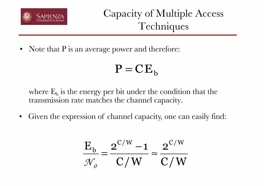
• Note that P is an average power and therefore:
where Eb is the energy per bit under the condition that the transmission rate matches the channel capacity.
bECP =
W/C2
W/C12E W/CW/C
b ≈−=0N
• Given the expression of channel capacity, one can easily find:

Capacity of Multiple Access Techniques : FDMA
• Suppose Nu FDMA users. Each user is allocated with a bandwidth W/Nu andtransmits power Pn=P/Nu. Therefore capacity Cn for user n is:
( ) !!"
#$$%
&+=!!
"
#$$%
&+=
00 NN W
PN1log
N
W
NW
P1log
N
WC nu
2uu
n2
un
• System capacity C for the network of Nu users is:
!!"
#$$%
&+=!!
"
#$$%
&+==
00 NN W
P1logW
W
PN1logWCNC 2
nu2nu
which shows that total capacity is equivalent to the case of a single user usingpower P = NuPn and all bandwidth W.
• Note that C increases with Nu but bandwidth allocation for a single userbecomes smaller.

Capacity of Multiple Access Techniques : TDMA
• In TDMA, each user is allocated with a Time Slot of normalized duration1/Nu. Each user transmits within its allocated time over the overallbandwidth W using total power P.
• The capacity per user is therefore the same as in FDMA:
!!"
#$$%
&+=!!
"
#$$%
&+=
00 NN W
P1log
N
W
W
P1logW
N
1C 2
u2
un
• When compared to FDMA: note that each user transmits with power PP = NuPn
although for a shorter time• When Nu increases, there is a practical limit for P beyond which a single user
cannot reasonably operate.

Capacity of Multiple Access Techniques : CDMA
In CDMA, each user transmits over the total bandwidth W with power Pn.
Let us consider two cases:
Case A - Users are non-cooperative (they ignore each other)
Case B - Users are cooperative (they know each other and coordinatewith one another)

Non-cooperative CDMA
• In this case at each receiver the signal originating from the (Nu-1) non-usefulusers are perceived as interfering noise.
• The capacity per user is thus:
( ) !!"
#$$%
&
−++=
nu
n2n P1NW
P1logWC
0N
• The total capacity is:
( ) !!"
#$$%
&
−++==
uu
u2unu N/P1NW
N/P1logWNCNC
0N
• Note that the relation of C to Nu is more complex than in FDMA andTDMA.
Power control

Cooperative CDMA
• In the case of cooperative users we can suppose that all users aresynchronized.
• The receiver knows all codes of all users and can jointly detect all signals withno interference between users.
• The total channel capacity is therefore:
!!"
#$$%
&+=!!
"
#$$%
&+=
00 NN W
P1logW
W
PN1logWC 2
nu2
which is the same of TDMA and FDMA.
• However, there is a fundamental difference in the present case whencompared to TDMA and FDMA
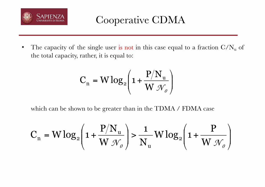
Cooperative CDMA
• The capacity of the single user is not in this case equal to a fraction C/Nu ofthe total capacity, rather, it is equal to:
!!"
#$$%
&+=
0NWNP
1logWC u2n
which can be shown to be greater than in the TDMA / FDMA case
!!"
#$$%
&+>!!
"
#$$%
&+=
00 NN W
P1logW
N
1
W
NP1logWC 2
u
u2n

Cooperative CDMA
while the rates of the single users must satisfy:
!!"
#$$%
&+<
0NWNP
1logWR u2i
• The aggregate rate R is thus bound by C:
!!"
#$$%
&+=<=∑
= 0NWP
1logWCRR 2
N
1ii
u

Comparison of capacity regions
• Example: N=2