Embed Size (px)
Citation preview
Features & Benefits
Down to 100 ps Rise Time
Real-time OscilloscopePlatform
Up to 4 GHz Bandwidth for Accurate SignalCharacterization
Up to 2.5 Gbps Optical and Electrical Serial Data Stream Rates
Built-in Compliance MaskTests Supporting a WideRange of Telecom andDatacom Standards
Broad Wavelength Optical Response Increases Versatility
Integrated Optical ReferenceReceiver Protects Integrity of System Calibration
Integrated Clock RecoveryProvides Single-connectionConvenience
32-Bit Serial Trigger for Isolation of Pattern-dependent Effects
Complete Eye PatternMeasurements Suite IncludingExtinction Ratio, Q-factor, EyeHeight/Width, Jitter and Noise
Waveform DatabaseAcquisition Technology for Accurate ParametricMeasurements on Eye Patterns
10 MHz Timebase Reference Input for Enhanced Synchronizationand Repeatability
Up to 20 GS/s Real-timeSample Rate
More than 400,000 wfms/secWaveform Capture Rate
TekConnectTM Interface forConvenient, High BandwidthSignal Connection
MultiView Zoom for QuickNavigation of Long Records
Open Access to the WindowsOperating Environment
Applications
Design Development andCompliance Testing of Optical and Electrical Signals
Physical LayerCharacterization ofCommunication Signals in Backplane, Midplane and Embedded Designs
Optical and Electrical SignalIntegrity, Margin Verification,Jitter and Timing Analysis
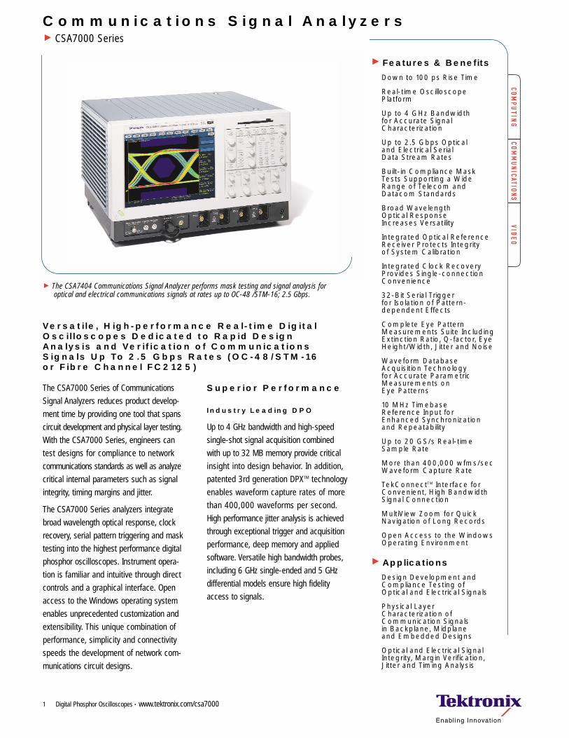
Communications Signal AnalyzersCSA7000 Series
Versatile, High-performance Real-time DigitalOscilloscopes Dedicated to Rapid Design Analysis and Verification of Communications Signals Up To 2.5 Gbps Rates (OC-48/STM-16 or Fibre Channel FC2125)
The CSA7404 Communications Signal Analyzer performs mask testing and signal analysis for optical and electrical communications signals at rates up to OC-48 /STM-16; 2.5 Gbps.
Digital Phosphor Oscilloscopes • www.tektronix.com/csa70001
The CSA7000 Series of Communications
Signal Analyzers reduces product develop-
ment time by providing one tool that spans
circuit development and physical layer testing.
With the CSA7000 Series, engineers can
test designs for compliance to network
communications standards as well as analyze
critical internal parameters such as signal
integrity, timing margins and jitter.
The CSA7000 Series analyzers integrate
broad wavelength optical response, clock
recovery, serial pattern triggering and mask
testing into the highest performance digital
phosphor oscilloscopes. Instrument opera-
tion is familiar and intuitive through direct
controls and a graphical interface. Open
access to the Windows operating system
enables unprecedented customization and
extensibility. This unique combination of
performance, simplicity and connectivity
speeds the development of network com-
munications circuit designs.
Superior Performance
Industry Leading DPO
Up to 4 GHz bandwidth and high-speed
single-shot signal acquisition combined
with up to 32 MB memory provide critical
insight into design behavior. In addition,
patented 3rd generation DPXTM technology
enables waveform capture rates of more
than 400,000 waveforms per second.
High performance jitter analysis is achieved
through exceptional trigger and acquisition
performance, deep memory and applied
software. Versatile high bandwidth probes,
including 6 GHz single-ended and 5 GHz
differential models ensure high fidelity
access to signals.
Digital Phosphor Oscilloscopes • www.tektronix.com/csa70002
Communication Signal AnalyzersCSA7000 Series
Clock Recovery
CSA7000 Series analyzers include clock
recovery for electrical and optical serial data
streams from 1.5 MBaud to 2.5 GBaud.
Users can easily and reliably perform mask
testing and parametric analysis with a single
connection. Recovered clock and data signals
are available on the front panel for connection
to other equipment, such as a BER analyzer.
Serial Pattern Trigger
The CSA7000 Series includes hardware-
based serial pattern trigger to isolate data
patterns. Serial trigger provides a direct
means to analyze pattern dependent issues,
even on a single-shot basis. The combination
of serial trigger and signal averaging reduces
random noise, enhancing acquisition of low
power signals. Users can specify patterns
with up to 32 bits, including “don’t-care”
bits. The serial trigger system can be clocked
from an external source or internal clock
recovery can be applied, providing single-
connection convenience.
UnprecedentedSimplicity
Integrated OpticalReference Receiver
Compliance testing for optical standards
requires calibrated optical reference receiver
response. CSA7000 Series models include
a broad wavelength optical input enabling
them to conveniently address a wide range
of standards. A complete library of optical
reference receiver filters ensures versatility
and eliminates the need for reconfiguring
external modules or plug-ins. Filters can
easily be disabled to provide full-bandwidth
analysis on optical signals. The CSA7404
includes reference receiver filters implementing
fourth-order Bessel-Thompson response for
the following standards and bit rates:
SONET/SDH
OC-48/STM16 FEC, OC-48/STM16,OC-12/STM4, OC-3/STM1, OC-1/STM0
VSR (1.24416 Gbps)
Fibre Channel 2125, 1063, 531, 266, 133
Gigabit Ethernet
InfiniBand 2.5 Gbps
IEEE 1394b S1600, S800, S400
The integrated O/E architecture of the
CSA7000 Series provides a robust, fully
calibrated signal path and eliminates the
need to match an external O/E adapter to a
specific instrument. The real-time architecture
of the CSA7000 Series is quickly user-
configurable with an optical channel and
three electrical inputs or with four electrical
inputs. The output of the O/E is available
on the front panel for use with other
instrumentation.
Mask Testing
The CSA7000 Series provides a complete
portfolio of masks for verifying compliance
to optical and electrical standards. Engineers
can verify circuit design performance and
perform interface compliance testing with
one real-time instrument, even when devel-
oping multi-standard and multi-rate designs.
Standard masks include:
SONET/SDH GR 253-Core (51.4 Mbps to 2.666 Gbps)
Ethernet IEEE Std 802.3, ANSI X3.263(125 Mbps to 1.25 Gbps)
Fibre Channel ANSI X3.230 (132.8 Mbps to 2.125 Gbps)
Fibre Channel Electrical (132.8 Mbps to 2.125 Gbps)
InfiniBand (2.5 Gbps)
ITU-T G.703 (1.544 Mbps to 155.52 Mbps)
ANSI T1.102 (1.544 Mbps to 155.52 Mbps)
USB (12 Mbps, 480 Mbps)
Serial ATA (1.5 Gbps)
IEEE 1394b (393 Mbps to 1.5729 Gbps)
PCI Express (2.5 Gbps)
Rapid I/O (500 Mbps to 2 Gbps)
SPI-5 (2.488 Gbps)
SFI-5 (2.488 Gbps)
TFI-5 (2.488 Gbps)
VSR (1.24416 Gbps)
Several powerful features allow users to easily
tailor mask testing for specific requirements:
One-button Autoset matches instrument settings to signal characteristics and specific mask requirements
Optional Auto-Fit process optimizes signalposition within the mask to minimize hits
Mask Margin control adjusts tolerance during testing
Hit-counting identifies location and degree of failures
Optional test-related actions including notification, logging and hardcopy
Built-in mask editing allowing users to copy and adjust mask values from a standard, or create new masks
Mask testing results are reported live, providing
real-time feedback. Mask hits are highlighted
on the display and accompanied by readouts
indicating waveforms tested, pass/fail results
and hit counts. A log file summarizing test
results can also be generated automatically.
Users can take advantage of the open Windows
platform to quickly copy and paste test result
screen images or log file information into
reports created with WordPad or other
applications on the instrument.
Digital Phosphor Oscilloscopes • www.tektronix.com/csa7000 3
Communication Signal AnalyzersCSA7000 Series
External Timebase Reference
The reference oscillator in CSA7000 Series
analyzers can be phase-locked to an external
10 MHz source to match system stability
or synchronize multiple instruments. This
phase-lock technique also enables charac-
terization of very low frequency wander and
modulation effects.
Waveform Database andParametric Measurements
The CSA7000 Series includes waveform
database acquisition mode to provide infor-
mation over a much larger sample of data.
The waveform database is a three-dimensional
accumulation of source waveform data as it
is continuously acquired. In addition to ampli-
tude and timing information, a waveform
database has a third dimension of count.
The count represents the number of times a
specific waveform point (time and amplitude)
has been acquired. Color-graded displays based
on counts can be used to highlight waveform
activity. Parametric measurements derived
from the database use statistical techniques
to produce more stable, accurate results.
CommunicationsMeasurements
The CSA7000 Series provides a broad suite
of eye-pattern related measurements that
are fundamental for analysis of serial com-
munications signals, including extinction
ratio, Q-factor, eye height/width, jitter and
noise. These are complemented with a wide
array of general purpose amplitude, time
and histogram-related measurements.
Application-specificSoftware Extensions
Applied measurement extensions can be
installed to enhance CSA7000 capabilities.
These software applications build on the
precision acquisition performance of
CSA7000 Series to address the need for
application-specific measurements to quickly
quantify device and system performance.
Optional applications include:
Advanced jitter analysis, including Rj/Dj separation and BER analysis
Compliance testing for signaling defined in ITU-T G.703 and ANSI T1.102 communications standards
Compliance testing for signaling defined inUSB1.0 standard and USB2.0 draft standard
Disk drive read channel, head and mediameasurements to IDEMA standards; PRML measurements
TDSET2 Ethernet compliance test softwarefor 10/100/1000Base-T
VocalLinkTM voice control software for TDS7000 Series instruments
Complete Connectivity
The CSA7000 Series combines a high performance real-time oscilloscope with aPC processor in a self-contained unit. Withopen access to the Windows operating environment, built-in applications such asWordPad, Paint and Internet Explorer allowusers to concurrently maintain lab notesand reference design information whileworking with the instrument, saving timeand reducing errors. The built-in floppy diskdrive provides a convenient means of trans-porting results while the standard networkinterfaces allow easy file sharing andremote control.
The analysis and connectivity software of theCSA7000 Series provides a comprehensivesoftware infrastructure for faster, more ver-satile operations. Industry-standard protocols,such as VISA and ActiveX Controls, areincluded for using and enhancing Windowsapplications such as Excel for data analysisand documentation. Or, create custom soft-ware to automate multi-step processes inwaveform collection and analysis with VisualBASIC, C, C++, MATLAB, HP VEE, and othercommon development environments. Byhosting applications on the instrument andusing the embedded PCI bus, waveform datacan be moved directly from the acquisitionsystem to analysis applications at much fasterspeeds than conventional cable connections.
Integration of the instrument with external PCsand non-Windows hosts is also supported byCSA7000 Series software solutions. Plug-and-play drivers are included to enable fastand easy communication with LabVIEW, LabWindows and HP VEE programs using GPIBand LAN connections. Applications using alocal area network can connect directly to a CSA7000 Series analyzer using the VXI11.2 server included in the instrument.
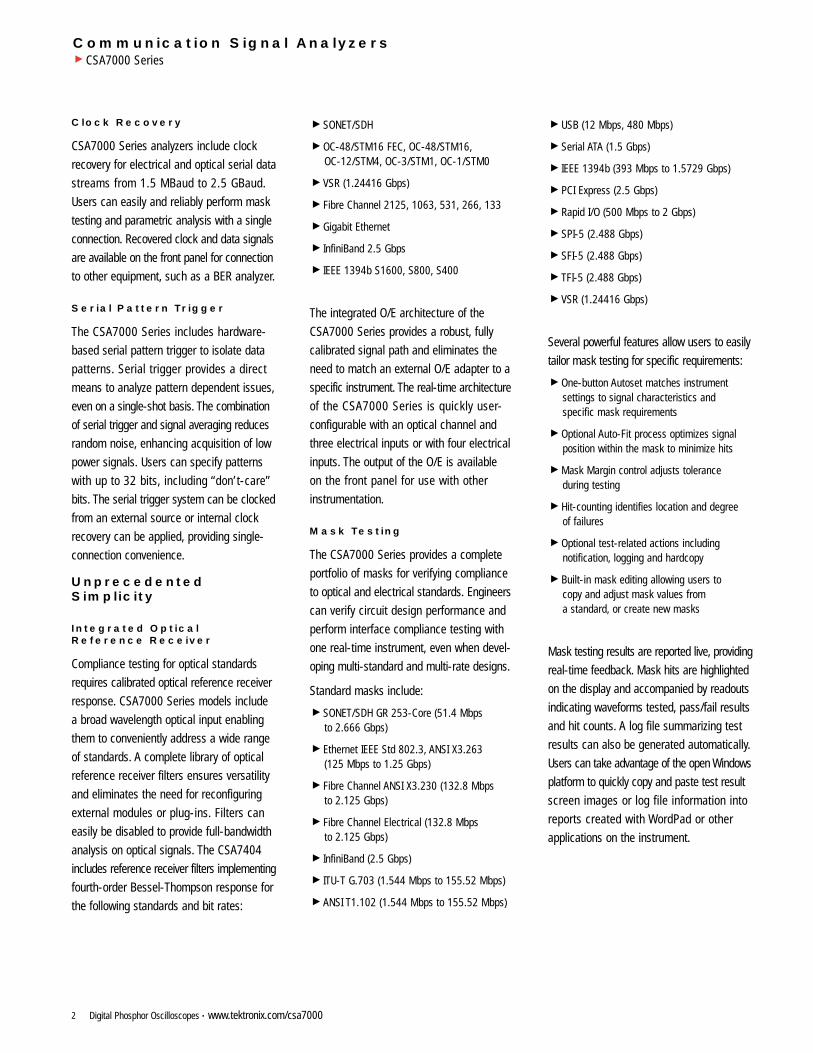
Figure 1. Versatile and easy to use,the CSA7000 Series combines optical reference receiver filters, clock recovery,serial pattern trigger and mask testing into a real-time oscilloscope.
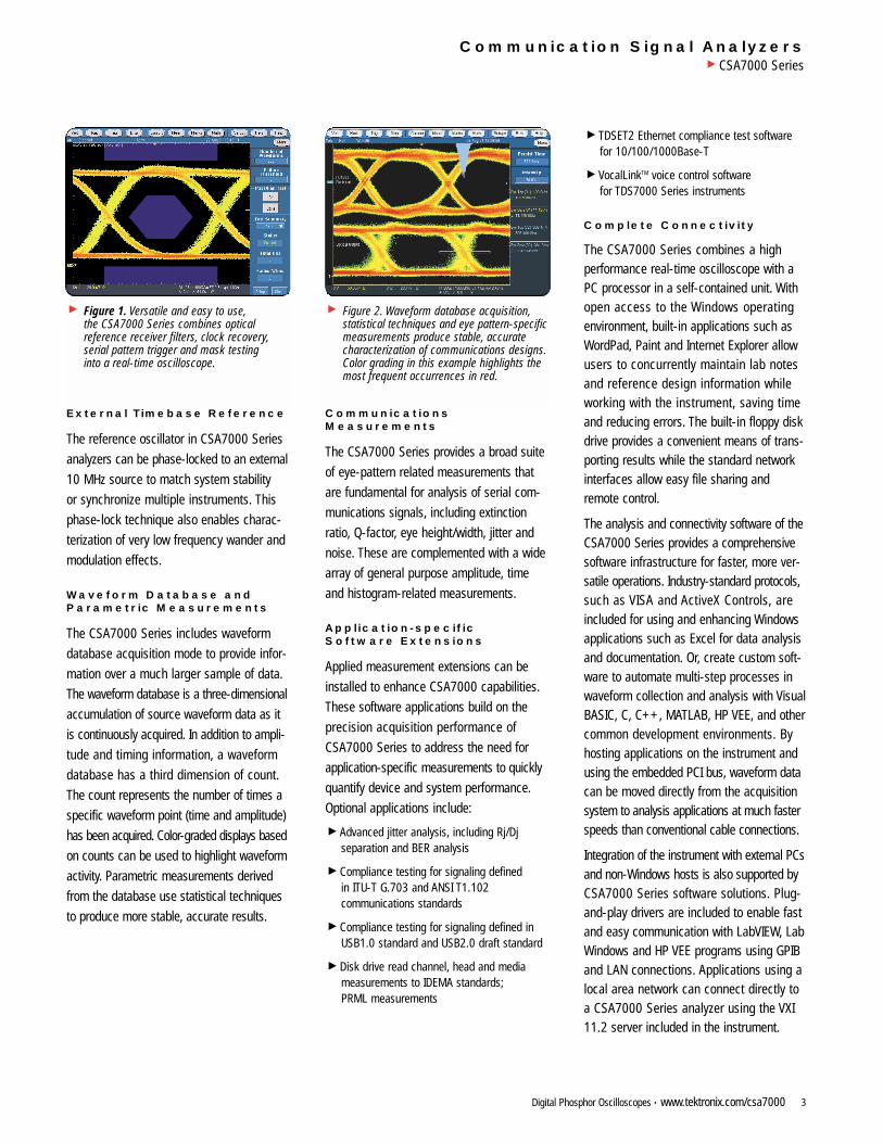
Figure 2. Waveform database acquisition,statistical techniques and eye pattern-specificmeasurements produce stable, accuratecharacterization of communications designs.Color grading in this example highlights themost frequent occurrences in red.
Communication Signal AnalyzersCSA7000 Series
Characteristics
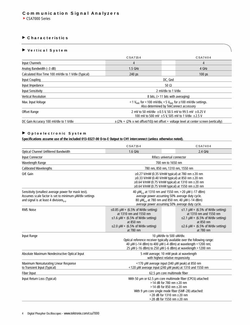
Vertical System
CSA7154 CSA7404
Input Channels 4 4
Analog Bandwidth (–3 dB) 1.5 GHz 4 GHz
Calculated Rise Time 100 mV/div to 1 V/div (Typical) 240 ps 100 ps
Input Coupling DC, Gnd
Input Impedance 50 ΩInput Sensitivity 2 mV/div to 1 V/div
Vertical Resolution 8 bits, (>11 bits with averaging)
Max. Input Voltage <1 VRMS for <100 mV/div, <5 VRMS for ≥100 mV/div settings.Also determined by TekConnect accessory
Offset Range 2 mV to 50 mV/div ±0.5 V, 50.5 mV to 99.5 mV ±0.25 V100 mV to 500 mV ±5 V, 505 mV to 1 V/div ±2.5 V
DC Gain Accuracy 100 mV/div to 1 V/div ±(2% + (2% x net offset/10)) net offset = voltage level at center screen (vertically)
Optoelectronic System
Specifications assume use of the included 013-0327-00 O-to-E Output to CH1 interconnect (unless otherwise noted).
CSA7154 CSA7404
Optical Channel Unfiltered Bandwidth 1.6 GHz 2.4 GHz
Input Connector Rifocs universal connector
Wavelength Range 700 nm to 1650 nm
Calibrated Wavelengths 780 nm, 850 nm, 1310 nm, 1550 nm
O/E Gain ≥0.27 V/mW (0.35 V/mW typical) at 780 nm ±20 nm≥0.33 V/mW (0.40 V/mW typical) at 850 nm ±20 nm≥0.64 V/mW (0.75 V/mW typical) at 1310 nm ±20 nm≥0.64 V/mW (0.75 V/mW typical) at 1550 nm ±20 nm
Sensitivity (smallest average power for mask test). 40 µWp-p at 1310 nm and 1550 nm. >20 µW (–17 dBm) Assumes scale factor is set to minimum µW/div settings average power assuming 50% average duty cycle.and signal is at least 4 divisionsp-p 80 µWp-p at 780 nm and 850 nm. 40 µW (–14 dBm)
average power assuming 50% average duty cycle.
RMS Noise ≤0.85 µW + (6.5% of W/div setting) ≤1.1 µW + (6.5% of W/div setting)at 1310 nm and 1550 nm at 1310 nm and 1550 nm
≤1.6 µW + (6.5% of W/div setting) ≤2.1 µW + (6.5% of W/div setting)at 850 nm at 850 nm
≤2.0 µW + (6.5% of W/div setting) ≤2.6 µW + (6.5% of W/div setting) at 780 nm at 780 nm
Input Range 10 µW/div to 500 uW/div.Optical reference receiver typically available over the following range:
40 µW (–14 dBm) to 400 µW (–4 dBm) at wavelength <1200 nm;25 µW (–16 dBm) to 250 µW (–6 dBm) at wavelength >1200 nm
Absolute Maximum Nondestructive Optical Input 5 mW average; 10 mW peak at wavelengthwith highest relative responsivity
Maximum Nonsaturating Linear Response <170 µW average input (340 µW peak) at 850 nmto Transient Input (Typical) <120 µW average input (240 µW peak) at 1310 and 1550 nm
Fiber Input 62.5 µm core multimode fiber
Input Return Loss (Typical) With 50 µm or 62.5 µm core multimode fiber (CPC6) attached:>14 dB for 780 nm ±20 nm>14 dB for 850 nm ±20 nm
With 9 µm core single mode fiber (SMF-28) attached:>28 dB for 1310 nm ±20 nm>28 dB for 1550 nm ±20 nm
Digital Phosphor Oscilloscopes • www.tektronix.com/csa70004
Digital Phosphor Oscilloscopes • www.tektronix.com/csa7000 5
Communication Signal AnalyzersCSA7000 Series
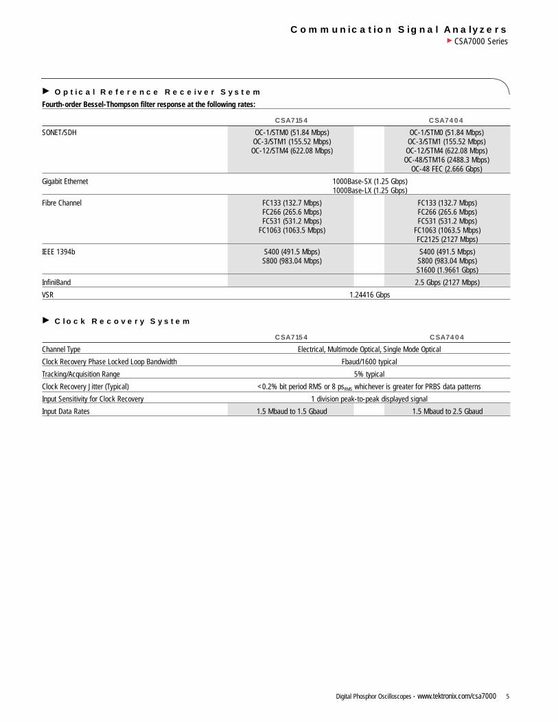
Optical Reference Receiver System
Fourth-order Bessel-Thompson filter response at the following rates:
CSA7154 CSA7404
SONET/SDH OC-1/STM0 (51.84 Mbps) OC-1/STM0 (51.84 Mbps)OC-3/STM1 (155.52 Mbps) OC-3/STM1 (155.52 Mbps)
OC-12/STM4 (622.08 Mbps) OC-12/STM4 (622.08 Mbps)OC-48/STM16 (2488.3 Mbps)
OC-48 FEC (2.666 Gbps)
Gigabit Ethernet 1000Base-SX (1.25 Gbps)1000Base-LX (1.25 Gbps)
Fibre Channel FC133 (132.7 Mbps) FC133 (132.7 Mbps)FC266 (265.6 Mbps) FC266 (265.6 Mbps)FC531 (531.2 Mbps) FC531 (531.2 Mbps)
FC1063 (1063.5 Mbps) FC1063 (1063.5 Mbps)FC2125 (2127 Mbps)
IEEE 1394b S400 (491.5 Mbps) S400 (491.5 Mbps)S800 (983.04 Mbps) S800 (983.04 Mbps)
S1600 (1.9661 Gbps)
InfiniBand 2.5 Gbps (2127 Mbps)
VSR 1.24416 Gbps
Clock Recovery System
CSA7154 CSA7404
Channel Type Electrical, Multimode Optical, Single Mode Optical
Clock Recovery Phase Locked Loop Bandwidth Fbaud/1600 typical
Tracking/Acquisition Range 5% typical
Clock Recovery Jitter (Typical) <0.2% bit period RMS or 8 psRMS whichever is greater for PRBS data patterns
Input Sensitivity for Clock Recovery 1 division peak-to-peak displayed signal
Input Data Rates 1.5 Mbaud to 1.5 Gbaud 1.5 Mbaud to 2.5 Gbaud
Digital Phosphor Oscilloscopes • www.tektronix.com/csa70006
Communication Signal AnalyzersCSA7000 Series
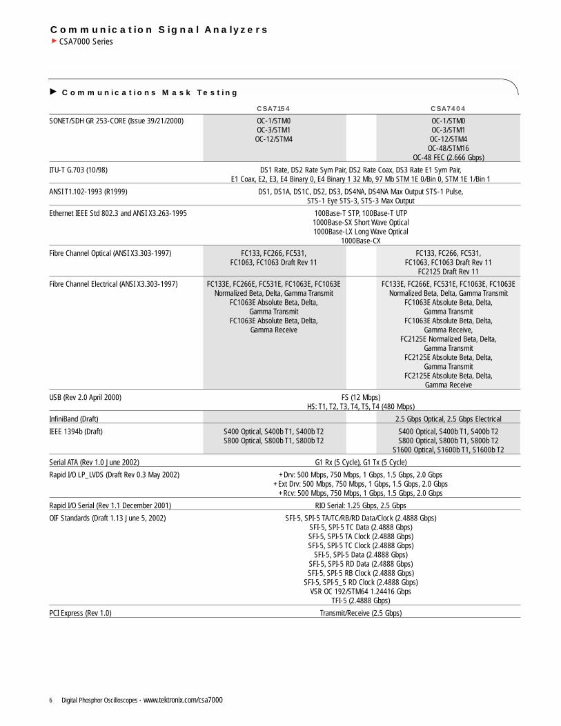
Communications Mask Testing
CSA7154 CSA7404
SONET/SDH GR 253-CORE (Issue 39/21/2000) OC-1/STM0 OC-1/STM0OC-3/STM1 OC-3/STM1
OC-12/STM4 OC-12/STM4OC-48/STM16
OC-48 FEC (2.666 Gbps)
ITU-T G.703 (10/98) DS1 Rate, DS2 Rate Sym Pair, DS2 Rate Coax, DS3 Rate E1 Sym Pair,E1 Coax, E2, E3, E4 Binary 0, E4 Binary 1 32 Mb, 97 Mb STM 1E 0/Bin 0, STM 1E 1/Bin 1
ANSI T1.102-1993 (R1999) DS1, DS1A, DS1C, DS2, DS3, DS4NA, DS4NA Max Output STS-1 Pulse,STS-1 Eye STS-3, STS-3 Max Output
Ethernet IEEE Std 802.3 and ANSI X3.263-1995 100Base-T STP, 100Base-T UTP1000Base-SX Short Wave Optical1000Base-LX Long Wave Optical
1000Base-CX
Fibre Channel Optical (ANSI X3.303-1997) FC133, FC266, FC531, FC133, FC266, FC531,FC1063, FC1063 Draft Rev 11 FC1063, FC1063 Draft Rev 11
FC2125 Draft Rev 11
Fibre Channel Electrical (ANSI X3.303-1997) FC133E, FC266E, FC531E, FC1063E, FC1063E FC133E, FC266E, FC531E, FC1063E, FC1063ENormalized Beta, Delta, Gamma Transmit Normalized Beta, Delta, Gamma Transmit
FC1063E Absolute Beta, Delta, FC1063E Absolute Beta, Delta,Gamma Transmit Gamma Transmit
FC1063E Absolute Beta, Delta, FC1063E Absolute Beta, Delta,Gamma Receive Gamma Receive,
FC2125E Normalized Beta, Delta,Gamma Transmit
FC2125E Absolute Beta, Delta,Gamma Transmit
FC2125E Absolute Beta, Delta,Gamma Receive
USB (Rev 2.0 April 2000) FS (12 Mbps)HS: T1, T2, T3, T4, T5, T4 (480 Mbps)
InfiniBand (Draft) 2.5 Gbps Optical, 2.5 Gbps Electrical
IEEE 1394b (Draft) S400 Optical, S400b T1, S400b T2 S400 Optical, S400b T1, S400b T2S800 Optical, S800b T1, S800b T2 S800 Optical, S800b T1, S800b T2
S1600 Optical, S1600b T1, S1600b T2
Serial ATA (Rev 1.0 June 2002) G1 Rx (5 Cycle), G1 Tx (5 Cycle)
Rapid I/O LP_LVDS (Draft Rev 0.3 May 2002) +Drv: 500 Mbps, 750 Mbps, 1 Gbps, 1.5 Gbps, 2.0 Gbps+Ext Drv: 500 Mbps, 750 Mbps, 1 Gbps, 1.5 Gbps, 2.0 Gbps
+Rcv: 500 Mbps, 750 Mbps, 1 Gbps, 1.5 Gbps, 2.0 Gbps
Rapid I/O Serial (Rev 1.1 December 2001) RIO Serial: 1.25 Gbps, 2.5 Gbps
OIF Standards (Draft 1.13 June 5, 2002) SFI-5, SPI-5 TA/TC/RB/RD Data/Clock (2.4888 Gbps)SFI-5, SPI-5 TC Data (2.4888 Gbps)SFI-5, SPI-5 TA Clock (2.4888 Gbps)SFI-5, SPI-5 TC Clock (2.4888 Gbps)
SFI-5, SPI-5 Data (2.4888 Gbps)SFI-5, SPI-5 RD Data (2.4888 Gbps)SFI-5, SPI-5 RB Clock (2.4888 Gbps)
SFI-5, SPI-5_5 RD Clock (2.4888 Gbps)VSR OC 192/STM64 1.24416 Gbps
TFI-5 (2.4888 Gbps)
PCI Express (Rev 1.0) Transmit/Receive (2.5 Gbps)
Digital Phosphor Oscilloscopes • www.tektronix.com/csa7000 7
Communication Signal AnalyzersCSA7000 Series
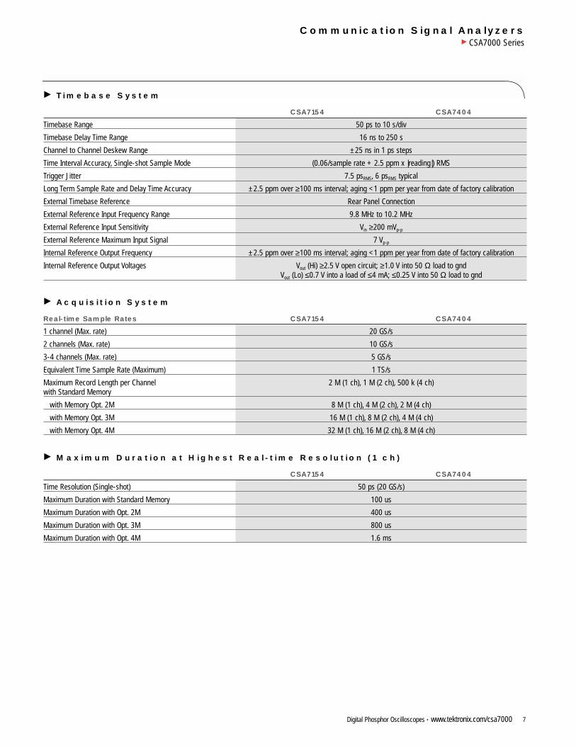
Timebase System
CSA7154 CSA7404
Timebase Range 50 ps to 10 s/div
Timebase Delay Time Range 16 ns to 250 s
Channel to Channel Deskew Range ±25 ns in 1 ps steps
Time Interval Accuracy, Single-shot Sample Mode (0.06/sample rate + 2.5 ppm x |reading|) RMS
Trigger Jitter 7.5 psRMS, 6 psRMS typical
Long Term Sample Rate and Delay Time Accuracy ±2.5 ppm over ≥100 ms interval; aging <1 ppm per year from date of factory calibration
External Timebase Reference Rear Panel Connection
External Reference Input Frequency Range 9.8 MHz to 10.2 MHz
External Reference Input Sensitivity Vin ≥200 mVp-p
External Reference Maximum Input Signal 7 Vp-p
Internal Reference Output Frequency ±2.5 ppm over ≥100 ms interval; aging <1 ppm per year from date of factory calibration
Internal Reference Output Voltages Vout (Hi) ≥2.5 V open circuit; ≥1.0 V into 50 Ω load to gndVout (Lo) ≤0.7 V into a load of ≤4 mA; ≤0.25 V into 50 Ω load to gnd
Acquisition System
Real-time Sample Rates CSA7154 CSA7404
1 channel (Max. rate) 20 GS/s
2 channels (Max. rate) 10 GS/s
3-4 channels (Max. rate) 5 GS/s
Equivalent Time Sample Rate (Maximum) 1 TS/s
Maximum Record Length per Channel 2 M (1 ch), 1 M (2 ch), 500 k (4 ch)with Standard Memory
with Memory Opt. 2M 8 M (1 ch), 4 M (2 ch), 2 M (4 ch)
with Memory Opt. 3M 16 M (1 ch), 8 M (2 ch), 4 M (4 ch)
with Memory Opt. 4M 32 M (1 ch), 16 M (2 ch), 8 M (4 ch)
Maximum Duration at Highest Real-time Resolution (1 ch)
CSA7154 CSA7404
Time Resolution (Single-shot) 50 ps (20 GS/s)
Maximum Duration with Standard Memory 100 us
Maximum Duration with Opt. 2M 400 us
Maximum Duration with Opt. 3M 800 us
Maximum Duration with Opt. 4M 1.6 ms
Digital Phosphor Oscilloscopes • www.tektronix.com/csa70008
Communication Signal AnalyzersCSA7000 Series
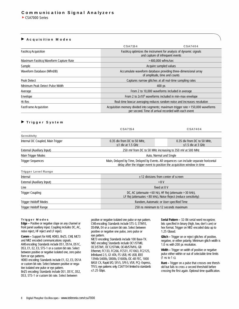
Trigger Modes Edge – Positive or negative slope on any channel orfront panel auxiliary input. Coupling includes DC, AC,noise reject, HF reject and LF reject.
Comm – Support for AMI, HDB3, BnZS, CMI, MLT3and NRZ encoded communications signals.AMI encoding: Standards include DS1, DS1A, DS1C,DS3, E1, E2, E3, STS-1 or a custom bit rate. Selectbetween positive or negative isolated one, zero pulseform or eye patterns.HDB3 encoding: Standards include E1, E2, E3, DS1Aor custom bit rate. Select between positive or nega-tive isolated one pulse or eye pattern.BnZS encoding: Standards include DS1, DS1C, DS2,DS3, STS-1 or custom bit rate. Select between
positive or negative isolated one pulse or eye pattern.CMI encoding: Standards include STS-3, STM1E,DS4NA, E4 or a custom bit rate. Select betweenpositive or negative one pulse, zero pulse or eye pattern.MLT3 encoding: Standards include 100 Base-TX.NRZ encoding: Standards include OC1/STM0,OC3/STM1, OC12/STM4, OC48/STM16, GBEthernet, FC133, FC266, FC531, FC1063, FC2125,Infiniband 2.5, G1 ATA, FS USB, HS USB, IEEE1394b S400b, S800b, S1600b, OC-48 FEC, 1000BASE CX, Rapid I/O, SFI-5, SPI-5, VSR, PCJ-Express,TFI-5; eye patterns only. CSA7154 limited to standards≤1.25 Gbps.
Serial Pattern – 32-Bit serial word recognizer,bits specified in binary (high, low, don’t care) orhex format. Trigger on NRZ-encoded data up to1.25 Gbaud.
Glitch – Trigger on or reject glitches of positive,negative, or either polarity. Minimum glitch width is1.0 ns with 200 ps resolution.
Width – Trigger on width of positive or negativepulse either within or out of selectable time limits(1 ns to 1 s).
Runt – Trigger on a pulse that crosses one thresh-old but fails to cross a second threshold beforecrossing the first again. Optional time qualification.
Acquisition Modes
CSA7154 CSA7404
FastAcq Acquisition FastAcq optimizes the instrument for analysis of dynamic signals and capture of infrequent events
Maximum FastAcq Waveform Capture Rate >400,000 wfms/sec
Sample Acquire sampled values
Waveform Database (WfmDB) Accumulate waveform database providing three-dimensional array of amplitude, time and counts
Peak Detect Captures narrow glitches at all real-time sampling rates
Minimum Peak Detect Pulse Width 400 ps
Average From 2 to 10,000 waveforms included in average
Envelope From 2 to 2x10⁹ waveforms included in min-max envelope
Hi-Res Real-time boxcar averaging reduces random noise and increases resolution
FastFrame Acquisition Acquisition memory divided into segments; maximum trigger rate >150,000 waveforms per second. Time of arrival recorded with each event
Trigger System
CSA7154 CSA7404
Sensitivity
Internal DC Coupled, Main Trigger 0.35 div from DC to 50 MHz, 0.35 div from DC to 50 MHz,≤1 div at 1.5 GHz ≤1.5 div at 3 GHz
External (Auxiliary Input) 250 mV from DC to 50 MHz increasing to 350 mV at 500 MHz
Main Trigger Modes Auto, Normal and Single
Trigger Sequences Main, Delayed by Time, Delayed by Events. All sequences can include separate horizontal delay after the trigger event to position the acquisition window in time
Trigger Level Range
Internal ±12 divisions from center of screen
External (Auxiliary Input) +8 V
Line fixed at 0 V
Trigger Coupling DC, AC (attenuate <60 Hz), HF Rej (attenuate >30 kHz),LF Rej (attenuates <80 kHz), Noise Reject (reduce sensitivity)
Trigger Holdoff Modes Random, Automatic or User-specified Time
Trigger Holdoff Range 250 ns minimum to 12 seconds maximum
Digital Phosphor Oscilloscopes • www.tektronix.com/csa7000 9
Communication Signal AnalyzersCSA7000 Series
Timeout – Trigger on an event which remainshigh, low, or either, for a specified time period,selectable from 1 ns to 1 s with 200 ps resolution.
Transition – Trigger on pulse edge rates that arefaster or slower than specified. Slope may be posi-tive, negative or either.
Setup/Hold – Trigger on violations of both setuptime and hold time between clock and data presenton any two input channels.
Pattern – Trigger when pattern goes false or staystrue for specified period of time. Pattern (AND, OR,NAND, NOR) specified for four input channelsdefined as HIGH, LOW or Don’t Care.
State – Any logical pattern of channels (1, 2, 3)clocked by edge on channel 4. Trigger on rising or falling clock edge.
Trigger Delay by Time – Trigger Delay by Time16 ns to 250 seconds.
Trigger Delay by Events – Trigger Delay by Events1 to 10,000,000 Events.
Waveform Measurements Amplitude – Amplitude, High, Low, Maximum,Minimum, Peak-to-Peak, Mean, Cycle Mean, RMS,Cycle RMS, Positive Overshoot, Negative Overshoot.
Time – Rise time, Fall time, Positive Width,Negative Width, Positive Duty Cycle, Negative DutyCycle, Period, Frequency, Delay.
Combination – Area, Cycle Area, Phase,Burst Width.
Histogram-related – Waveform count, Hits in box,Peak hits, Median, Maximum, Minimum, Peak-to-Peak, Mean (µ), Standard Deviation (σ), µ+1σ,µ+2σ, µ+3σ.
Eye Pattern-related – Extinction Ratio (absolute,% and dB), Eye Height, Eye Top, Eye Base, EyeWidth, Crossing %, Jitter (peak-to-peak, RMS and6σ), Noise (peak-to-peak and RMS), S/N ratio,Cycle Distortion, Q-factor.
Waveform Processing/Math Algebraic Expressions – Define extensive algebraic expressions including waveforms,scalars and results of parametric measurementse.g., (Integral (Ch. 1-Meas(Ch. 1))*1.414.
Arithmetic – Add, subtract, multiply, divide waveforms and scalars.
Relational – Boolean result of comparison >, <, ≥,≤, ==, !=.
Calculus – Integrate, differentiate.
Frequency Domain Functions – Spectral magnitudeand phase, real and imaginary spectra.
Vertical Units – Magnitude: Linear, dB, dBm.Phase: Degrees, Radians.
Window Functions – Rectangular, Hamming,Hanning, Kaiser-Bessel, Blackman-Harris,Gaussian, Flattop2, Tek Exponential.
Waveform Definitions – Waveform definition as arbitrary math expressions.
Display Characteristics Display Type – Liquid crystal active-matrix colordisplay; integral touch screen.
Display Size – 211.2 mm (W) x 158.4 mm (H),264 mm (10.4 in.) diagonal.
Display Resolution – 640 horizontal x 480 vertical pixels.
Waveform Styles – Vectors, Dots, VariablePersistence, Infinite Persistence.
Computer System and Peripherals CPU – 850 MHz Celeron Processor.
PC System Memory – 512 MB.
Hard Disk Drive – Rear-panel, removable harddisk drive, 20 GB capacity.
Floppy Disk Drive – Front-panel 3.5 in. floppy diskdrive, 1.44 MB capacity.
CD-RW Drive – Rear-panel CD-RW drive.
Mouse – Logitech thumb wheel model included,USB interface.
Keyboard – Order 118-9402-00 for small keyboard (fits in pouch); PS-2 interface.Order 119-6297-00 for full-size keyboard; USB interface and hub.
Input/Output Ports Probe Compensation Output – Front-panel BNCconnector, requires Probe Cal-Deskew Fixture(included) for probe attachment. 400 mV ±20% into>10 kΩ load (VOH=2 V, VOL=1.6 V typical). 200 mV±20% into a 50 Ω load (VOH=1 V, VOL=0.8 typical).
Recovered Clock Out – Front-panel SMA connec-tor provides output of clock signal recovered fromspecified channel. Output compatible with ECL terminated with 50 Ω to GND. Peak-to-peak outputswing at 650 MHz is at least 200 mV into 50 Ω.Higher frequencies will be further attenuated byapproximately 6 dB per octave above 625 MHz.
Recovered Data Out – Front-panel SMA connectorprovides regenerated data output from clock recov-ery system. Serial data output baud rate ≤1250MBaud. Output swing at this baud rate will be atleast 200 mV into 50 Ω.
Optical In – Optoelectronic converter input,700 nm to 1650 nm, Rifocs connector.
O/E Output – Front-panel BMA connector providingelectrical output of optoelectronic converter. SMAadapter included.
Analog Signal Output Amplitude – Rear-panelBNC connector, provides a buffered version of thesignal that is attached to the Channel 3 input whenChannel 3 is selected as trigger source. Frequencyresponse: 1 GHz into a 50 Ω load. Amplitude:20 mV/div ±20% into a 1 MΩ load, 10 mV/div±20% into a 50 Ω load.
Auxiliary Output – Rear-panel BNC connector,provides a TTL-compatible, polarity switchablepulse when the oscilloscope triggers or optionally,upon mask test failure or test completion.
External Timebase Reference In – Rear-panelBNC connector, timebase system can phase-lock to external 10 MHz reference.
Timebase Reference Out – Rear-panel BNC connector, provides TTL-compatible output of internal 10 MHz reference oscillator.
Parallel Port – IEEE 1284, DB-25 connector.
Audio Ports – Miniature phone jacks for stereomicrophone input and stereo line output.
USB Port – Allows connection or disconnection of USB keyboard, mouse or other peripherals whileoscilloscope power is on.
Keyboard Port – PS-2 compatible.
Mouse Port – PS-2 compatible.
LAN Port – RJ-45 connector, supports 10Base-Tand 100Base-T.
Serial Port – DB-9 COM1 port.
SVGA Video Port – DB-15 female connector; connect a second monitor to use dual-monitor display mode. Supports Basic requirements ofPC99 specifications.
GPIB Port – IEEE 488.2 standard.
Scope VGA Video Port – DB-15 female connector,31.6 kHz sync, EIA RS-343A compliant, connect toshow the oscilloscope display, including live waveforms on an external monitor or projector.
Power Source Power – 100 to 240 VRMS, ±10%, 50/60 Hz CAT II.115 VRMS ±10%, 400 Hz CAT II.<300 Watts (450 VA).
Digital Phosphor Oscilloscopes • www.tektronix.com/csa700010
Communication Signal AnalyzersCSA7000 Series
PhysicalCharacteristics BENCHTOP CONFIGURATION Dimensions mm in.Height 277 10.9 Width 455 17.9 Depth 425 16.75 Weight kg lb.Net 18 39.6 Shipping 37 81.4
RACKMOUNT CONFIGURATION Dimensions mm in.Height 277 10.9 Width 502 19.75 Depth 486 19.125 Weight kg lb.Net 19 41.8 Shipping 5.6 12.32
MECHANICAL Required Clearance mm in.Top 0 or >76 0 or >3 Bottom 0 0 Left side 76 3 Right side 76 3 Front 0 0 Rear 0 0
Environmental Temperature – Operating: 0 ºC to +50 ºC, excluding floppy disk and CD-ROM drives.+10 ºC to +45 ºC, including floppy disk and CD-ROM drives.Nonoperating: –22 ºC to +60 ºC.
Humidity – Operating: 20% to 80% relative humidity with amaximum wet bulb temperature of +29 ºC at orbelow +50 ºC, noncondensing. Upper limit deratedto 25% relative humidity at +50 ºC.Nonoperating: With no diskette in floppy disk drive,5% to 90% relative humidity with a maximum wetbulb temperature of +29 ºC at or below +60 ºC,noncondensing. Upper limit derated to 20% relativehumidity at +60 ºC.
Altitude – Operating: 10,000 ft. (3,048 m).Nonoperating: 40,000 ft. (12,190 m).
Random Vibration – Operating: 0.00015 g2/Hz from 5 to 350 Hz,–3 dB/octave from 350 to 500 Hz,0.000105 g2/Hz at 500 Hz.Overall level of 0.27 gRMS.Nonoperating: 0.0175 g2/Hz from 5 to 100 Hz,–3 dB/octave from 100 to 200 Hz,0.0875 g2/Hz from 200 to 350 Hz,–3 dB/octave from 350 to 500 Hz,0.006132 g2/Hz at 500 Hz.Overall level of 2.28 gRMS.
Electromagnetic Compatibility – EN 61326 (EU EMC Directive 89/336EEC).
AS/NZS 2064 (Australian EMC Framework).
Safety – UL 3111-1, CSA-22.2 No. 1010.1,EN61010-1.
Ordering Information
CSA7404
4 GHz Communications Signal Analyzer.
CSA7154
1.5 GHz Communications Signal Analyzer.
All Models Include: Accessory pouch, front cover,mouse, probe calibration and deskew fixture (067-0405-xx), O/E Electrical Output to Ch. 1 Input Adapter (013-0327-xx), Fiber cleaning kit (020-2357-xx), Quick Reference (020-2404-xx),User Manual (071-7010-xx), GPIB Programmer’sReference, TDS/CSA7000 Series Product SoftwareCD-ROM, TDS/CSA7000 Series operating systemrestoration CD-ROM, Optional ApplicationsSoftware CD-ROM, Oscilloscope Analysis andConnectivity Made Easy Kit, Option SM and STUser Manual (071-1035-xx), Performance verifica-tion procedure PDF file, NIST, MIL-STD-45662A,ISO9000 Calibration Certificate and Power Cord.
CSA7404 also includes: (4) TekConnectTM to SMAadapters (TCA-SMA).
CSA7154 also includes: (4) TekConnect to BNCadapters (TCA-BNC).
Please specify power plug when ordering.
RecommendedAccessories
Probes and Converters
P7260 – 6 GHz Low Capacitance Active VoltageProbe (TekConnect).
P7350 – 5 GHz Differential Probe (TekConnect).
P6150 – 9 GHz Low Capacitance Passive VoltageProbe (requires TCA-SMA adapter).
P6158 – 3 GHz Low Capacitance Passive VoltageProbe (requires TCA-BNC adapter).
CT6 – 2 GHz AC Current Probe (requires TCA-BNC adapter).
CT1 – 1 GHz AC Current Probe (requires TCA-BNC adapter).
P6701B – Optical-to-Electrical Converter; 500 nmto 950 nm (requires TCA-BNC adapter).
P6703B – Optical-to-Electrical Converter;1100 nm to 1650 nm (requires TCA-BNC adapter).
TCP202 – DC to 50 MHz Current Probe (requires TCA-BNC adapter).
Test Fixtures
TDSUSBF– USB test fixture to be used in conjunction with Opt. USB.
Software
VocalLinkTM Pro – VCLNKP VocalLink Pro VoiceControlled Software.
VocalLinkTM Basic – VCLNKB VocalLink Basic Voice Controlled Software.
WSTRO– WavestarTM waveform capture and documentation software.
Miscellaneous
Keyboard – Fits in pouch, PS-2 interface; Order 118-9402-00.
Keyboard – Full-size, USB interface; Order 119-6633-00.
Service Manual – Order 071-7011-00.
Transit Case – Order 016-1522-00.
GPIB Cable (1M) – Order 012-0991-01.
GPIB Cable (2M) – Order 012-0991-00.
Centronics Cable – Order 012-1214-00.
Optical Connector Adapters
FC/PC – Order 119-5115-00.
SC/PC – Order 119-5116-00.
ST/PC – Order 119-4513-00.
DIN/PC 47256 – Order 119-4546-00.
Diamond 2.5 – Order 119-4556-00.
Diamond 3.5 – Order 119-4558-00.
SMA 2.5 – Order 119-4517-00.
SMA – Order 119-4557-00.
Adapters
TCA75 – 4 GHz precision TekConnect 75 Ω to 50 Ω adapter with 75 Ω BNC input connector.
TCA-SMA – TekConnect-to-SMA Adapter.
TCA-BNC – TekConnect-to-BNC Adapter.
TCA-N – TekConnect-to-N Adapter.
TCA-1 Meg – 1 Meg amplifier, high impedancebuffer 1 MΩ/10 pF, TekProbe BNC-to-TekConnect;includes P6139A.
AFTDS – Telecom differential electrical interfaceadapter (for line rates <8 Mbps; requires TCA-BNC adapter).
AMT75 – 1 GHz precision 75 Ω adapter (for linerates >8 Mbps; requires TCA-BNC adapter).
Digital Phosphor Oscilloscopes • www.tektronix.com/csa7000 11
Communication Signal AnalyzersCSA7000 Series
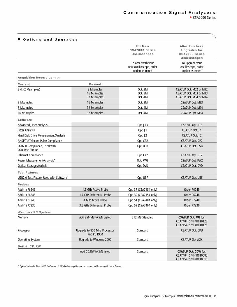
Options and Upgrades
For New After PurchaseCSA7000 Series Upgrades forOscilloscopes CSA7000 Series
Oscilloscopes
To order with your To upgrade yournew oscilloscope, order oscilloscope, order
option as noted option as noted
Acquisition Record Length
Current Desired
Std. (2 Msamples) 8 Msamples Opt. 2M CSA7UP Opt. M02 or M12 16 Msamples Opt. 3M CSA7UP Opt. M03 or M13 32 Msamples Opt. 4M CSA7UP Opt. M04 or M14
8 Msamples 16 Msamples Opt. 3M CSA7UP Opt. M23
8 Msamples 32 Msamples Opt. 4M CSA7UP Opt. M24
16 Msamples 32 Msamples Opt. 4M CSA7UP Opt. M34
Software
Advanced Jitter Analysis Opt. JT3 CSA7UP Opt. JT3
Jitter Analysis Opt. J1 CSA7UP Opt. J1
Hard Disk Drive Measurement/Analysis Opt. J2 CSA7UP Opt. J2
ANSI/ITU Telecom Pulse Compliance Opt. CP2 CSA7UP Opt. CP2
USB2.0 Compliance, Used with Opt. USB CSA7UP Opt. USB USB Test Fixture
Ethernet Compliance Opt. ET2 CSA7UP Opt. ET2
Power Measurement/Analysis*1 Opt. PW2 CSA7UP Opt. PW2
Optical Storage Analysis Opt. DVD CSA7UP Opt. DVD
Test Fixtures
USB2.0 Test Fixture, Used with Software Opt. UBF CSA7UP Opt. UBF
Probes
Add (1) P6245 1.5 GHz Active Probe Opt. 37 (CSA7154 only) Order P6245
Add (1) P6248 1.7 GHz Differential Probe Opt. 39 (CSA7154 only) Order P6248
Add (1) P7240 4 GHz Active Probe Opt. 51 (CSA7404 only) Order P7240
Add (1) P7330 3.5 GHz Differential Probe Opt. 52 (CSA7404 only) Order P7330
Windows PC System
Memory Add 256 MB to S/N Listed 512 MB Standard CSA7UP Opt. MU for:CSA7404: S/N <B010128CSA7154: S/N <B010121
Processor Upgrade to 850 MHz Processor Standard CSA7UP Opt. CPUand PC RAM
Operating System Upgrade to Windows 2000 Standard CSA7UP Opt W2K
Built-in CD/RW
Add CD/RW to S/N listed Standard CSA7UP Opt. CDW for:CSA7404: S/N <B010083CSA7154: S/N <B010015
*1Option 3M and a TCA-1MEG TekConnect 1 MΩ buffer amplifier are recommended for use with this software.
Communication Signal AnalyzersCSA7000 Series
Our most up-to-date product information is available at:www.tektronix.com
Copyright © 2003, Tektronix, Inc. All rights reserved. Tektronix products are coveredby U.S. and foreign patents, issued and pending. Information in this publicationsupersedes that in all previously published material. Specification and price changeprivileges reserved. TEKTRONIX and TEK are registered trademarks of Tektronix,Inc. All other trade names referenced are the service marks, trademarks or regis-tered trademarks of their respective companies.
02/03 HB/WWW 55W-15048-3
Digital Phosphor Oscilloscopes • www.tektronix.com/csa700012
Instrument Options and Upgrades
Mounting
Opt. 1K – K4000 Scope cart.
Opt. 1R – Rackmount kit.
Service
Opt. C3 – Calibration Service 3 Years.
Opt. C5 – Calibration Service 5 Years.
Opt. D1 – Calibration Data Report.
Opt. D3 – Calibration Data Report 3 Years (with Option C3).
Opt. D5 – Calibration Data Report 5 Years (with Option C5).
Opt. R3 – Repair Service 3 Years.
Opt. R5 – Repair Service 5 Years.
Power Plug Options
Opt. A0 – US Plug, 115 V, 60 Hz.
Opt. A1 – Euro Plug, 220 V, 50 Hz.
Opt. A2 – UK Plug, 240 V, 50 Hz.
Opt. A3 – Australian Plug, 240 V, 50 Hz.
Opt. A5 – Swiss Plug, 220 V, 50 Hz.
Opt. A99 – No Power Cord.
Opt. AC – China Plug, 50 Hz.
Contact Tektronix:
ASEAN / Australasia / Pakistan (65) 6356 3900
Austria +43 2236 8092 262
Belgium +32 (2) 715 89 70
Brazil & South America 55 (11) 3741-8360
Canada 1 (800) 661-5625
Central Europe & Greece +43 2236 8092 301
Denmark +45 44 850 700
Finland +358 (9) 4783 400
France & North Africa +33 (0) 1 69 86 80 34
Germany +49 (221) 94 77 400
Hong Kong (852) 2585-6688
India (91) 80-2275577
Italy +39 (02) 25086 1
Japan 81 (3) 3448-3010
Mexico, Central America & Caribbean 52 (55) 56666-333
The Netherlands +31 (0) 23 569 5555
Norway +47 22 07 07 00
People’s Republic of China 86 (10) 6235 1230
Poland +48 (0) 22 521 53 40
Republic of Korea 82 (2) 528-5299
Russia, CIS & The Baltics +358 (9) 4783 400
South Africa +27 11 254 8360
Spain +34 (91) 372 6055
Sweden +46 8 477 6503/4
Taiwan 886 (2) 2722-9622
United Kingdom & Eire +44 (0) 1344 392400
USA 1 (800) 426-2200
USA (Export Sales) 1 (503) 627-1916
For other areas contact Tektronix, Inc. at: 1 (503) 627-7111
Updated 20 September 2002
Product(s) are manufactured in ISO registered facilities.