Embed Size (px)
Citation preview

485i-Module-IA-en-16 | 98-0007716 | Version 1.6 EN
Communication Interface for SMA Inverters485 Data ModuleInstallation Manual

SMA Solar Technology AG Table of Contents
Installation Manual 485i-Module-IA-en-16 3
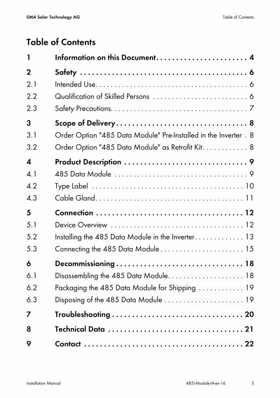
Table of Contents1 Information on this Document. . . . . . . . . . . . . . . . . . . . . . . 42 Safety . . . . . . . . . . . . . . . . . . . . . . . . . . . . . . . . . . . . . . . . . . 62.1 Intended Use. . . . . . . . . . . . . . . . . . . . . . . . . . . . . . . . . . . . . . . . 62.2 Qualification of Skilled Persons . . . . . . . . . . . . . . . . . . . . . . . . . 62.3 Safety Precautions. . . . . . . . . . . . . . . . . . . . . . . . . . . . . . . . . . . . 73 Scope of Delivery . . . . . . . . . . . . . . . . . . . . . . . . . . . . . . . . . 83.1 Order Option "485 Data Module" Pre-Installed in the Inverter . 83.2 Order Option "485 Data Module" as Retrofit Kit . . . . . . . . . . . . 84 Product Description . . . . . . . . . . . . . . . . . . . . . . . . . . . . . . . 94.1 485 Data Module . . . . . . . . . . . . . . . . . . . . . . . . . . . . . . . . . . . 94.2 Type Label . . . . . . . . . . . . . . . . . . . . . . . . . . . . . . . . . . . . . . . . 104.3 Cable Gland. . . . . . . . . . . . . . . . . . . . . . . . . . . . . . . . . . . . . . . 115 Connection . . . . . . . . . . . . . . . . . . . . . . . . . . . . . . . . . . . . . 125.1 Device Overview . . . . . . . . . . . . . . . . . . . . . . . . . . . . . . . . . . . 125.2 Installing the 485 Data Module in the Inverter. . . . . . . . . . . . . 135.3 Connecting the 485 Data Module . . . . . . . . . . . . . . . . . . . . . . 156 Decommissioning . . . . . . . . . . . . . . . . . . . . . . . . . . . . . . . . 186.1 Disassembling the 485 Data Module. . . . . . . . . . . . . . . . . . . . 186.2 Packaging the 485 Data Module for Shipping . . . . . . . . . . . . 196.3 Disposing of the 485 Data Module . . . . . . . . . . . . . . . . . . . . . 197 Troubleshooting . . . . . . . . . . . . . . . . . . . . . . . . . . . . . . . . . 208 Technical Data . . . . . . . . . . . . . . . . . . . . . . . . . . . . . . . . . . 219 Contact . . . . . . . . . . . . . . . . . . . . . . . . . . . . . . . . . . . . . . . . 22
Information on this Document SMA Solar Technology AG
4 485i-Module-IA-en-16 Installation Manual
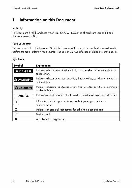
1 Information on this DocumentValidityThis document is valid for device type "485I-MOD-G1 BGCB" as of hardware version B5 and firmware version 4.00.
Target GroupThis document is for skilled persons. Only skilled persons with appropriate qualification are allowed to perform the tasks set forth in this document (see Section 2.2 "Qualification of Skilled Persons", page 6).
SymbolsSymbol Explanation
Indicates a hazardous situation which, if not avoided, will result in death or serious injuryIndicates a hazardous situation which, if not avoided, could result in death or serious injuryIndicates a hazardous situation which, if not avoided, could result in minor or moderate injuryIndicates a situation which, if not avoided, could result in property damage
Information that is important for a specific topic or goal, but is not safety-relevant
☐ Indicates an essential requirement for achieving a specific goal☑ Desired result✖ A problem that might occur

SMA Solar Technology AG Information on this Document
Installation Manual 485i-Module-IA-en-16 5
Typographies
Nomenclature
Abbreviations
FiguresThe figures in this document can vary slightly for inverters of types STP 1x000TL-10, STP xx000TLHE-10, STP xx000TLEE-10, SB x000TL-21 and WB xx00TL-21.
Typography Explanation Examplebold • Display messages
• Elements of a user interface• Connections• Elements to be selected• Elements to be entered
• The value can be read from the Energy field.
• Select Settings.• Enter the value 10 in the
Minutes field.
> • Connects several elements that are to be selected
• Select Settings > Date.
[Button/Key] • Button or key to be selected or pressed
• Select [Next].
Complete designation Designation in this documentElectronic Solar Switch ESSPV plant PlantSMA inverter Inverter
Abbreviation Designation ExplanationAC Alternating Current ‒DC Direct Current ‒
Safety SMA Solar Technology AG
6 485i-Module-IA-en-16 Installation Manual
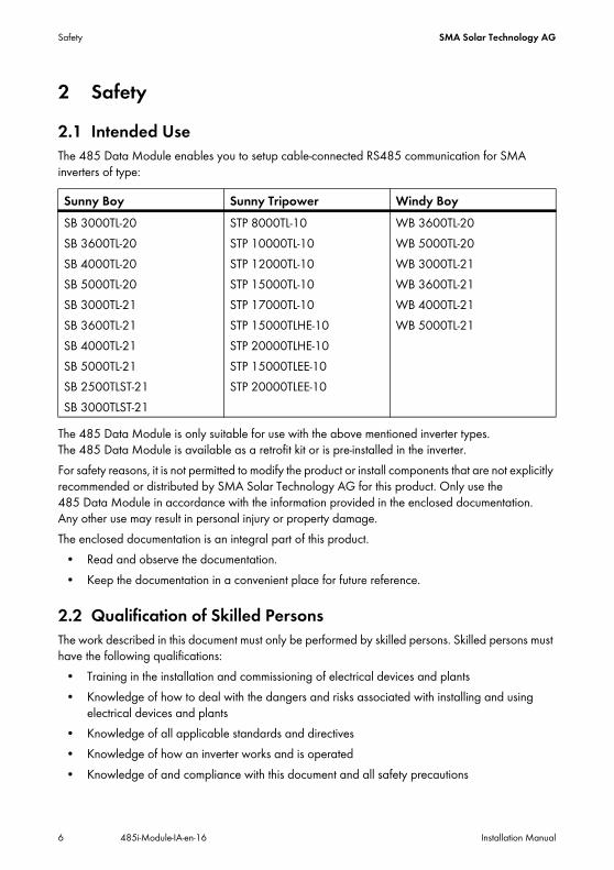
2 Safety2.1 Intended UseThe 485 Data Module enables you to setup cable-connected RS485 communication for SMA inverters of type:
The 485 Data Module is only suitable for use with the above mentioned inverter types. The 485 Data Module is available as a retrofit kit or is pre-installed in the inverter.For safety reasons, it is not permitted to modify the product or install components that are not explicitly recommended or distributed by SMA Solar Technology AG for this product. Only use the 485 Data Module in accordance with the information provided in the enclosed documentation. Any other use may result in personal injury or property damage.The enclosed documentation is an integral part of this product.
• Read and observe the documentation.• Keep the documentation in a convenient place for future reference.
2.2 Qualification of Skilled PersonsThe work described in this document must only be performed by skilled persons. Skilled persons must have the following qualifications:
• Training in the installation and commissioning of electrical devices and plants• Knowledge of how to deal with the dangers and risks associated with installing and using
electrical devices and plants• Knowledge of all applicable standards and directives• Knowledge of how an inverter works and is operated• Knowledge of and compliance with this document and all safety precautions
Sunny Boy Sunny Tripower Windy BoySB 3000TL-20SB 3600TL-20SB 4000TL-20SB 5000TL-20SB 3000TL-21SB 3600TL-21SB 4000TL-21SB 5000TL-21SB 2500TLST-21SB 3000TLST-21
STP 8000TL-10STP 10000TL-10STP 12000TL-10STP 15000TL-10STP 17000TL-10STP 15000TLHE-10STP 20000TLHE-10STP 15000TLEE-10STP 20000TLEE-10
WB 3600TL-20WB 5000TL-20WB 3000TL-21WB 3600TL-21WB 4000TL-21WB 5000TL-21

SMA Solar Technology AG Safety
Installation Manual 485i-Module-IA-en-16 7
2.3 Safety PrecautionsElectric ShockLethal voltages are present in the conductive parts of the inverter.
• Prior to performing any work on the inverter, disconnect the inverter from any voltage sources on the AC and DC sides (see inverter installation manual).
Burn HazardsSome parts of the inverter enclosure can get hot during operation.
• During operation, touch the inverter on the enclosure lid only.
Environmental InfluencesWhen closed and with the ESS plugged in, the inverter has the degree of protection IP65. The inverter is thus protected against dust intrusion and water penetration. Dust intrusion and water penetration can damage the inverter.
• If the ESS is not plugged in, the inverter must be protected against dust and water.• Firmly plug the ESS in again after performing any work on the inverter.
Electrostatic DischargeBy touching electronic components, you can damage or even destroy the inverter through electrostatic discharge (ESD).
• Earth yourself before touching any inverter components.
Disturbance of Data Transmission due to AC CablesDuring operation, AC cables generate an electromagnetic field which may induce interference in plant communication.
• Lay the cables for RS485 communication using suitable fastening material and with a minimum clearance of 50 mm to the AC cables.

Scope of Delivery SMA Solar Technology AG
8 485i-Module-IA-en-16 Installation Manual
3 Scope of Delivery3.1 Order Option "485 Data Module" Pre-Installed in the InverterCheck the delivery for completeness and any visible external damage. Contact your specialist dealer if the delivery is incomplete or you find any damage.
Figure 1: Components included in the scope of delivery: 485 Data Module pre-installed in the inverter
3.2 Order Option "485 Data Module" as Retrofit KitCheck the delivery for completeness and any visible external damage. Contact your specialist dealer if the delivery is incomplete or you find any damage.
Figure 2: Components included in the scope of delivery for the 485 Data Module as retrofit kit
Position Quantity DescriptionA 1 Installation manualB 1 Technical Description "RS485 Cabling Plan"C 1 Cable gland
Position Quantity DescriptionA 1 485 Data Module with:
• 2 conductive adhesive foils• 1 plug• 1 plug with a connected terminator
B 1 Cable glandC 1 Installation manualD 1 Technical Description "RS485 Cabling Plan"

SMA Solar Technology AG Product Description
Installation Manual 485i-Module-IA-en-16 9
4 Product Description4.1 485 Data ModuleThe 485 Data Module enables you to setup cable-connected RS485 communication for SMA inverters.
Figure 3: Design of the 485 Data Module
Position DescriptionA Hexagon socket screwB PlugC Plug with connected resistorD Ribbon cable plugE Ribbon cableF Type label

Product Description SMA Solar Technology AG
10 485i-Module-IA-en-16 Installation Manual
4.2 Type LabelThe type label clearly identifies the 485 Data Module. The type label is located at the bottom right on the back of the 485 Data Module.
Figure 4: Information on the type label
You require the information on the type label to use the 485 Data Module safely and for customer support from the SMA Service Line. The type label must be permanently affixed to the 485 Data Module.
Symbol on the Type Label
Position Description ExplanationA Serial No. Serial number of the 485 Data ModuleB Version Hardware version of the 485 Data ModuleC Type Device type
Symbol Description ExplanationCE marking The 485 Data Module complies with the requirements of the
applicable EC directives.

SMA Solar Technology AG Product Description
Installation Manual 485i-Module-IA-en-16 11
4.3 Cable GlandThe cable gland provides a sturdy, tightly sealed connection of the cables with the inverter enclosure. The cable gland also protects the inverter from dust intrusion and moisture penetration.
Figure 5: Product description: Cable gland
Position DescriptionA Filler-plugB SealC Swivel nutD Counter nut

Connection SMA Solar Technology AG
12 485i-Module-IA-en-16 Installation Manual
5 Connection5.1 Device Overview
Figure 6: Overview of the connection area
Position DescriptionA Flipped up display with screwB Cable route to the plugs of the 485 Data ModuleC Inverter enclosure opening for cable glandD Mounting position of the 485 Data Module in the inverter

SMA Solar Technology AG Connection
Installation Manual 485i-Module-IA-en-16 13
5.2 Installing the 485 Data Module in the Inverter
2. Loosen the screw of the display until the display can be flipped up.
3. Flip up the display until it clicks into place.4. Push the pre-mounted filler-plug out of the second
hole from the left in the inverter enclosure.
5. Attach the cable gland with the counter nut to the enclosure opening.
1.Danger to life due to electric shock when opening the inverterDeath or serious injuries
• Disconnect the inverter from voltage sources on the AC and DC sides and open it (see the inverter installation manual).
Connection SMA Solar Technology AG
14 485i-Module-IA-en-16 Installation Manual
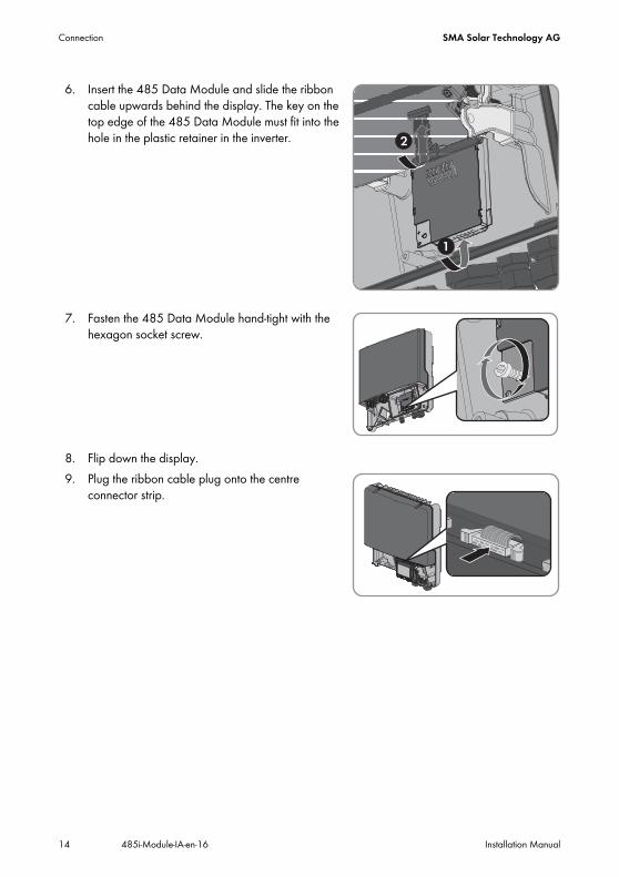
6. Insert the 485 Data Module and slide the ribbon cable upwards behind the display. The key on the top edge of the 485 Data Module must fit into the hole in the plastic retainer in the inverter.
7. Fasten the 485 Data Module hand-tight with the hexagon socket screw.
8. Flip down the display.9. Plug the ribbon cable plug onto the centre
connector strip.

SMA Solar Technology AG Connection
Installation Manual 485i-Module-IA-en-16 15
5.3 Connecting the 485 Data ModuleTo achieve a good signal quality, observe the cable recommendation (see technical description "RS 485 Cabling Plan")
Procedure:To connect the 485 Data Module, perform the following actions in the prescribed sequence. The following sections show the exact sequence.
• Preparing the cable• Connecting the cable to the 485 Data Module
Preparing the Cable1. Remove 40 mm of the cable sheath at the end of the cable which is to be connected to the
485 Data Module.2. Shorten the cable shield to 15 mm.3. Fold the surplus cable shield back onto the cable
sheath.
4. Wrap the cable shield with conductive adhesive foil.
5. Strip the insulation on the three wires by 6 mm. Two wires for communication must be a twisted pair.6. Shorten all other wires flush with the cable sheath.
Disturbance of Data Transmission due to AC CablesDuring operation, AC cables generate an electromagnetic field which may induce interference in plant communication.
• Lay the RS485 communication cables using suitable fastening material and with a minimum clearance of 50 mm to the AC cables.

Connection SMA Solar Technology AG
16 485i-Module-IA-en-16 Installation Manual
Connecting the Cable to the 485 Data Module1. Flip up the display until it clicks into place.2. Unscrew the swivel nut of the cable gland on the
inverter.
3. Press the seal out of the cable gland from the inside.
4. Route the cable from the outside into the inverter through the loose swivel nut and the cable gland.5. Remove one of the filler-plugs from the seal for each
cable.
6. Insert the cable into the seal.
SMA Solar Technology AG Connection
Installation Manual 485i-Module-IA-en-16 17
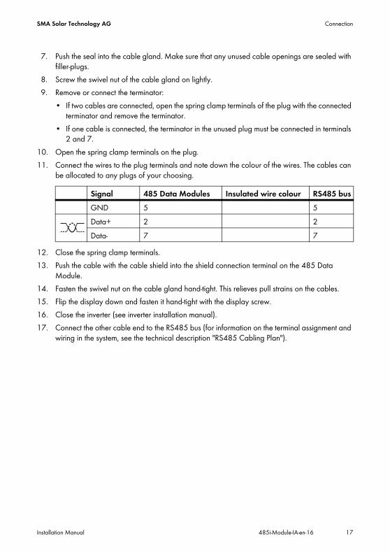
7. Push the seal into the cable gland. Make sure that any unused cable openings are sealed with filler-plugs.
8. Screw the swivel nut of the cable gland on lightly.9. Remove or connect the terminator:
• If two cables are connected, open the spring clamp terminals of the plug with the connected terminator and remove the terminator.
• If one cable is connected, the terminator in the unused plug must be connected in terminals 2 and 7.
10. Open the spring clamp terminals on the plug.11. Connect the wires to the plug terminals and note down the colour of the wires. The cables can
be allocated to any plugs of your choosing.
12. Close the spring clamp terminals.13. Push the cable with the cable shield into the shield connection terminal on the 485 Data
Module.14. Fasten the swivel nut on the cable gland hand-tight. This relieves pull strains on the cables.15. Flip the display down and fasten it hand-tight with the display screw.16. Close the inverter (see inverter installation manual).17. Connect the other cable end to the RS485 bus (for information on the terminal assignment and
wiring in the system, see the technical description "RS485 Cabling Plan").
Signal 485 Data Modules Insulated wire colour RS485 busGND 5 5Data+ 2 2Data- 7 7

Decommissioning SMA Solar Technology AG
18 485i-Module-IA-en-16 Installation Manual
6 Decommissioning6.1 Disassembling the 485 Data Module
2. Press the left-hand and right-hand lock hooks outwards and remove the ribbon cable plug from the centre connector strip of the inverter.
3. Loosen the screw of the display until the display can be flipped up.4. Flip up the display until it clicks into place.5. Unscrew the swivel nut of the cable gland.6. Open the spring clamp terminals of the plug on the 485 Data Module.7. Remove the cables from the 485 Data Module.8. Unscrew the counter nut of the cable gland9. Pull the cable gland and cables out of the inverter.
10. Release the screw of the 485 Data Module and remove the 485 Data Module.11. Close the spring clamp terminals of the plugs on the 485 Data Module.12. Flip down the display and fasten the display screw hand-tight.13. Seal the inverter enclosure opening with the filler-plug for enclosure openings.14. Close the inverter (see inverter installation manual).
1.Danger to life due to electric shock when opening the inverterDeath or serious injuries
• Disconnect the inverter from voltage sources on the AC and DC sides and open it (see the inverter installation manual).
2
1
1
SMA Solar Technology AG Decommissioning
Installation Manual 485i-Module-IA-en-16 19
6.2 Packaging the 485 Data Module for Shipping• Pack the 485 Data Module. Use the original packaging or packaging that is suitable for the
weight and size of the 485 Data Module.
6.3 Disposing of the 485 Data Module• Dispose of the 485 Data Module in accordance with the regulations for the disposal of
electronic waste applicable at the installation site.orReturn the 485 Data Module to SMA Solar Technology AG at your own expense labelled "ZUR ENTSORGUNG" ("FOR DISPOSAL") (see Section 9 "Contact", page 22).

Troubleshooting SMA Solar Technology AG
20 485i-Module-IA-en-16 Installation Manual
7 TroubleshootingProblem Cause and corrective measuresThe emergency channel list "Emergncy" or "EmgncyXX" is displayed in the communication product (e. g. Sunny WebBox, Sunny Explorer).The inverter is displayed by device class "Other" in the Sunny Portal.
The 485 Data Module is installed in an inverter without first disconnecting the inverter on the AC and DC sides. That prevents the inverter detecting the new 485 Data Module.Corrective measures:
• Prior to performing any work on the inverter, disconnect the inverter from any voltage sources on the AC and DC sides (see inverter installation manual).
Several SMA communication products query data simultaneously from the devices via Bluetooth (e.g. Sunny Explorer, Sunny Beam with Bluetooth) and RS485 communication (e.g. Sunny WebBox).This can cause data congestion if a lot of data is transmitted simultaneously. If this condition lasts for more than five minutes, the inverter resets the 485 Data Module. Due to the data congestion, the inverter cannot detect the 485 Data Module after the reset.Corrective measures:
• Wait until the inverter restarts the next morning, then the inverter will detect the 485 Data Module.orDisconnect the inverter from voltage sources on the AC and DC sides and recommission it (see the inverter installation manual).

SMA Solar Technology AG Technical Data
Installation Manual 485i-Module-IA-en-16 21
8 Technical DataMechanical Data
Communication
Connections
Ambient Conditions during Operation
Ambient Conditions for Storage/Transport
Width x height x depth 73 mm x 88 mm x 34 mmWeight 71 g
Communication interface RS485Maximum cable length 1,200 m
Type of plug 4-pole spring clamp terminalNumber of RS485 connections 2
Ambient temperature − 25°C … +85°CRelative humidity, non-condensing 5% … 95%Maximum height above sea level (MSL) 3,000 m
Ambient temperature − 40°C … +85°CRelative humidity, non-condensing 5% … 95%Maximum height above sea level (MSL) 3,000 m

Contact SMA Solar Technology AG
22 485i-Module-IA-en-16 Installation Manual
9 ContactIf you have technical problems concerning our products, contact the SMA Service Line. We require the following information in order to provide you with the necessary assistance:
• Type, serial number and firmware version of the inverter• Type, serial number, hardware and firmware version of the 485 Data Module• Number of 485 Data Modules connected
SMA Solar Technology AGSonnenallee 134266 Niestetal, Germanywww.SMA.de
SMA Service Line Inverters: +49 561 9522 1499Communication: +49 561 9522 2499Fax: +49 561 9522 4699E-Mail: [email protected]

SMA Solar Technology AG Legal Restrictions
Installation Manual 485i-Module-IA-en-16 23
The information contained in this document is the property of SMA Solar Technology AG. Publishing its content, either partially or in full, requires the written permission of SMA Solar Technology AG. Any internal company copying of the document for the purposes of evaluating the product or its correct implementation is allowed and does not require permission.
SMA Factory WarrantyThe current guarantee conditions come enclosed with your device. These are also available online at www.SMA.de and can be downloaded or are available on paper from the usual sales channels if required.
TrademarksAll trademarks are recognized even if these are not marked separately. Missing designations do not mean that a product or brand is not a registered trademark.The Bluetooth® word mark and logos are registered trademarks owned by Bluetooth SIG, Inc. and any use of such marks by SMA Solar Technology AG is under license.SMA Solar Technology AGSonnenallee 134266 NiestetalGermanyTel. +49 561 9522-0Fax +49 561 9522-100www.SMA.deE-Mail: [email protected]© 2004 to 2012 SMA Solar Technology AG. All rights reserved