Embed Size (px)
DESCRIPTION
commissioning
Citation preview

COMMISSIONING PHILOSOPHY

INDEX
CHAPTER SECTION TITLE PAGE
1 INTRODUCTION 41 Purpose 42 Standards and Codes 43 Safety 44 Organization 45 Scope 56 References 57 Definitions 6
2 PRELIMINARY ACTIVITIES 71 Pre-Commissioning Witnessing 72 Preliminary Checks, Introduction 7
2.1 Purpose 72.2 Principles 7
3 Operators Preliminary Checks 73.1 Piping 73.2 Vessels 103.3 Safety Equipment 11
4 Mechanical Preliminary Checks 114.1 Review of Documentation 114.2 Review of Facilities 12
5 Electrical Preliminary Checks 125.1 Review of Documentation 125.2 Review of Facilities 12
6 Instrument Preliminary Checks 146.1 Review of Documentation 146.2 Review of Facilities 14
7 Reports 157.1 Punchlists raised by Operator 157.2 Task reports 16
3 FUNCTIONAL TESTS 171 Introduction 17
1.1 Purpose of Functional Test 171.2 Functional Testing 171.3 Functional Disciplines 171.4 Test Reporting 17
2 Electrical Functional Testing 172.1 Introduction 172.2 Functional Test Sheets 182.3 General Function Test Sheets 18
3 Instrument Functional Testing 183.1 Introduction 183.2 P or PD Transmitter 18
Abo Commissioning Philosophy RevA page 2 of 37

3.3 Level Transmitter, Displacement Type 183.4 Temperature Transmitter, Thermocouple Type 193.5 Temperature Transmitter, Resistance Type 193.6 Alarm and Trip Setting 193.7 Converter 193.8 Positioner and Control Valve 193.9 Heat Detector 193.10 Smoke Detector 203.11 UV Detector 203.12 Gas Detector 203.13 Analyzer 203.14 SDV 203.15 BDV 203.16 Instrument Functional Test Sheet 21
4 PRE-START UP ACTIVITIES 221 Introduction 222 Leak Tests 22
2.1 Introduction 222.2 Test Specifications 232.3 Test Procedures General 232.4 Low Pressure Leak Test 232.5 High Pressure Leak Test 242.6 Atmospheric Vessels 25
3 Dry-Out 253.1 Introduction 253.2 Dry-out Specifications 25
5 OPERATIONAL TESTS 261 Introduction 26
1.1 Purpose 261.2 Principle 261.3 Contents of Operational Test 26
2 Scope of Tests 262.1 List of Operational Tests 262.2 Operational Tests of Process and Utilities 272.3 Operational Tests of ESD and F&G Systems 29
6 ADDITIONAL ACTIVITIES 311 Support Activities 312 Documentation Tasks 31
2.1 Technical Data Base 312.2 Punch lists 312.3 Drawings Updating 322.4 Filing of Commissioning Activities 322.5 Hand-over Dossier 32
APPENDIX A Pre-commissioning witnessing 34APPENDIX B Instrument functional test sheets 35APPENDIX C Electrical functional test sheets 36
Abo Commissioning Philosophy RevA page 3 of 37

INTRODUCTION
1. Purpose
The purpose of the Commissioning Philosophy Guidelines is to provide the information, the procedures and the supporting documents, in order to carry out the commissioning activities in a pre-planned, safe and efficient manner.
2 Standards and Codes
The Commissioning Team will comply with the Project and/or Company Specifications referenced in the NAE contractual documentation.
3 Safety
The Commissioning Team will be responsible for the execution of the “Permit to Work” system as in force, and comply with the Company safety rules and local regulations.
Competent and experienced personnel will carry out the commissioning activities.
Commissioning will be responsible for its internal safety organization and control.
4 Organization
The Commissioning Team’s activities will be carried-out by Group (System), or Subsystems called WORKPACKS, and a sequence will be established to meet the start-up priorities.The WORKPACKS generally follow the same boundaries as referred to in the “Tagging Procedure”, Reference: Prosafe engineering document 255-DOC-091, Annex A
The transfer of responsibilities from the Prosafe Construction Team to the Prosafe Commissioning team will take place on a Subsystem basis. The transfer will take place when a Subsystem has reached the “Ready for Commissioning” status, including all Construction/Precommissioning documentation already signed and completed by all relevant parties, and formalized by both parties signing a “Ready for Commissioning” Certificate, with a mutually agreed “Ready for Commissioning “ Punch list attached.
The above will include transfer of the responsibility for operations, maintenance and safety of the Subsystem. The accepting party will then become responsible, but this does not relieve the Prosafe Construction Team from their contractual obligations.
Abo Commissioning Philosophy RevA page 4 of 37

5 Scope
The scope of work of the commissioning activities will include the following:
Pre-commissioning witnessing Review of Prosafe Construction Team Pre-commissioning documentation Preliminary checks Functional test Pre-startup activities Operational tests Support activities Documentation tasks
The scope of this Document is to provide the ABO FPSO Commissioning Team/ Personnel with guidance to commission the plant and equipment, on the FPSO Facility.This includes work done by (sub) contractors
Note: All Precommissioning and Commissioning procedures for the Topsides equipment related to the Subsea Control System (SCS) are to be supplied by NAE direct contractor ABB. Also, NAE is responsible for the acceptance of Custody Transfer Meters, Cargo Tank calibration, and Safety and ESD systems.
6 References
ABO PROCESS PFD’s & P&ID’s
ABO SHIP UTILITIES PFD’s & P&ID's
Leak Test Procedure
P&ID Checking and Compilation Check List
Tagging Procedure, including Pipe Color CodingEng Doc 255-DOC-091
PSV’s Register – ABO Topside Facilities and Ship Utilities
ABO FPSO Component List
Critical Function Testing Procedures of the ABO FPSO Process Shutdown Switches, Maintenance and Critical Function Testing Manual.
List of Instrumentation with their Alarms & Shutdown setpoints for the Oil Stabilization Train, Gas Compression Facilities and Water Injection Plant
Valve Alignment Matrixes
ABO Cause And Effect Charts
Abo Commissioning Philosophy RevA page 5 of 37
7 Definitions
Commissioning Activities on ABO FPSO
Activities carried out on equipment, part of plant, or plant by the Commissioning Team/ Commissioning Personnel starting from the completion of Conversion until the FPSO Facility is handed over to Production for Process start-up.
Pre-commissioning Activities (cold, de-energized tests)
Activities carried out by the Sub Contractor / 3rd Party, or Prosafe’s Internal Personnel on equipment prior to completion of Installation, eg, component conformity checks, setting of PSV’s, Piping hydrotesting/flushing and cleaning, machinery cold alignments, electrical/instruments cable continuity, electrical protection relays setting, Instrument calibrations at random, and Internal Vessel Inspection.
Commissioning Team / Commissioning Personnel
Designate any organization and its member assigned by Contract, or by a PROSAFE Internal arrangement, to carry out commissioning activities on FPSO Facility plant and equipment.
Hand Over Dossier
Documents, which contain all the information required to demonstrate to the Prosafe Production Team that the system has reached the “Ready for Hand-Over” Status. This will include Hand-over certificate, all Drawings, Database print-out, Preliminary checks, reports, Functional test sheets, Operational Test Procedure, Vendor information, Hand-over punch list.
FPSO Facility Operator is Prosafe Production Pte Ltd.
Sub Contractors are GSI, Keppel Shipyard, Boustead and other Vendors.
PRELIMINARY ACTIVITIESAbo Commissioning Philosophy RevA page 6 of 37
1 Pre-commissioning Witnessing
The Commissioning Team will perform witnessing of critical pre-commissioning activities, i.e.
Factory Acceptance Tests (FAT) Setting of PSV’s – Done by Sub Contractor(s) Piping hydrotesting / flushing and cleaning – Done by Sub Contractor(s) Machinery cold alignments – Done by Sub Contractor(s) Electrical protection relay setting – Done by Sub Contractor(s) Instrumentation calibrations at random – Done by Sub Contractor(s) Internal vessel inspection – Done by Sub Contractor(s)
Relevant test sheets will be countersigned by the Commissioning Team and filed according to procedure, see Chapter 6.
2 Preliminary Checks, Introduction
2.1 Purpose
Preliminary checks are the first task of site commissioning activities and should ensure that the contractor has completed his scope of work. The checks are carried out on a subsystem basis, and by discipline.
2.2 Principles
When the pre-commissioning scope is complete, the commissioning team will receive formal notification. Before acceptance, the Commissioning Team will assess that all pre-commissioning tasks have been completed:
Review of As-built drawings and Precom documentation.
Visual verification the subsystem by Mechanical, Electrical/Instrument and Operational teams. (Normally no dismantling will be required).
Upon completion of the inspection, each discipline will compile punch lists.
3 Operators Preliminary Checks
3.1 Piping
3. 1.1. Review Documentation
Confirm all piping has been FLUSHED and PRESSURE tested by the Sub Contractor(s) and all relevant documents filled out, signed and formally transmitted to the Commissioning Team Leader.
Abo Commissioning Philosophy RevA page 7 of 37
Confirm certificates of PSVs and selected Hull Valves are available, and transfer these documents formally to the Commissioning Team Leader.
Confirm all “As-built” documentation is available, i.e., PID’s, Isometric drawings, Electrical connection drawings or details, manuals, PLC software, parts listings, etc. and these are to be formally transmitted to the Commissioning Team Leader in a timely manner.
3.1.2 Review of Facilities
The operator will “walk the lines”, and verify the operability and conformity using the As-built PID’s, with special attention to the following:
Non Return Valves (NRV), control and globe valves: Check if installed with flow arrow in correct direction
All valves: Are packing followers correctly tightened and will open/close smoothly Are hand wheels clear from obstructions Are valves tagged correctly CSO/CSC are clearly marked on the P&ID’s, and installed correctly on
valves
Sample connections: Check accessibility
Pump strainers: Can the strainer be depressurized and drained Can a hose be connected Can a bucket be used Can the strainer element be pulled without hindrance
Spectacle blinds: Can they be turned easily, and installed as per PIDs Confirm that the Spectacle Blinds have been assigned Tag Numbers and are tagged properly
Piping: Piping low and high points, slopes Check if in accordance with P&ID’s Check if drains and vents are installed with caps or plugs
Pipe supports: Check pipe clamps are tight Check Teflon pads are correctly installed when applicable
Steam traps: Checked if installed correctly Check relief to a safe location
Abo Commissioning Philosophy RevA page 8 of 37
Check integrity of isolation and by-pass
Pressure Safety valves: If vented to atmosphere: confirm outlet is supported and drainable if there
is a low point drain. If PSV’s are paired, check the lock system and that they are properly Car
Seal Open (CSO) or Car Seal Closed (CSC), and that the Car Seal has been properly installed, and that the valve is in the proper position as per the P&ID’s and the Valve Alignment Matrix
Insulation: Check if insulation is in good condition Check that the insulation cannot become water saturated
Earthing: Confirm that earth straps are installed properly, as per drawings
Gaskets and Joints: Confirm that correct material and ratings are used
Blinds: Confirm that a blind list has been prepared Confirm the blinds have ID numbers, which is attached to the handle The blind list must contain the following info: Line number, size and service
Blind numberBlind size and rating
Accessibility: Check accessibility of valves and other equipment
Safety: Check all safety aspects i.e. protruding valve spindles
Operability:- Check operability aspects such as location of pressure gauges, sight
glasses, etc.- Check Teflon pads are installed correctly
Color coding: Confirm all pipes and valves follow the applicable color-coding format.
Tagging: Confirm all valves and equipment follow the correct tagging format
3.2 Vessels
3.2.1 Classification
The following equipment is considered as a vessel:
Abo Commissioning Philosophy RevA page 9 of 37
- Drums, Separators, KO Drum, Surge Vessels, Air Receivers, Surge and Contactor Drums, Electrostatic Dehydrator, Electrostatic Desalter, Still Column, Reboiler
- Boilers, Steam Generators, Furnace- Inert Gas Scrubber- Heat Exchangers- Pig Receivers, Launchers- Oily Water Separators
3.2.2 Review of Documentation:
Confirm all vessels have been pressure tested, cleaned, and dried, and all relevant documents completed, signed, and formally transmitted to the Commissioning Team Leader
Confirm all internals have been correctly installed and checked-off
Confirm all “As-built” documentation is complete, and has been formally transmitted to the Commissioning Team Leader
3.2.3 Internal Checks
The Construction Team/Contractors will invite the commissioning team for internal inspection prior to closing the vessels. They should give at least 24 hours notification for these inspections 3 Phase Separator
- Ensure seal of adjustable Weir Plates are tight and do not leak- Verify that all nozzles are free from debris- Check tightness of internal Parts
Electrostatic Dehydrator & Desalter- Ensure that Electrical connections and fittings are correct
- Check tightness of all internal parts
3.2.4 External Checks
All vessels: Verify the name plates and confirm all details are correct Ensure bolting of manways with new gaskets Ensure security of ladders and walkways Ensure that nozzles are perpendicular, with no damage
Towers: Check trays, tray supports and bolting Check valves or bubble cap trays
Drums: Check wire mesh pads, vortex breaker, perforated plates, weirs, spray
nozzles etc. are securely attached
Abo Commissioning Philosophy RevA page 10 of 37
Pig Receivers: Check Trap Door opening mechanism
Boilers: Check refractory, walls, etc.
Tagging: Confirm all vessels have correct nameplate details, and tag number
3.3 Safety Equipment
Most safety equipment checks will be performed by the E&I discipline technician(s) (F&G Detection System, Fusible Loops, deluge, etc.). However, life saving and fire fighting equipment preliminary checks will be performed by the safety department.
Verify accessibility to all life saving equipment (lifeboats, rafts, life jackets).
Verify accessibility to fire fighting equipment (extinguishers, hydrants, monitors).
Check escape ways, ladders and stairs are secure, free of sharp edges, obstacles and debris, and are clearly marked and adequately illuminated.
Verify that all equipment lists are filled and signed.
4 Mechanical Preliminary Checks
The checks will be carried-out on rotating equipment i.e. pumps, compressors, diesel engines, gas engines electric motors, turbines, cranes, HVAC units, etc.
4.1 Review of Documentation
The technician(s) will review the pre-commissioning report and confirm that:
All rotating equipment has been cold aligned (where applicable) and alignment records are available and have been formally transmitted to the Commissioning Team Leader
Couplings and guards have been installed. Suction and discharge piping are correctly installed and free of stresses. Suction strainers are installed with strainer element in place. Fans and drivers have been correctly aligned, and fan pitch and clearance have
been set. All relevant checklists have been filled out and signed. All “As-built” documentation is complete, and has been formally transmitted to
the Commissioning Team Leader.
4.2 Review of Facilities
Abo Commissioning Philosophy RevA page 11 of 37
The technician will visually inspect all mechanical equipment based on the following documents:
Installation Drawings and Details PID’s Vendor drawings and manuals Data sheets
The following items will be systemically addressed during the survey:
Nameplates External damage to paint and insulation Conformity to project standards and codes, vendor drawings and
recommendations Safety rules and good practice Ancillary equipment: Quality of installation Availability of lubricating and seal oil fluids in quantity and quality Free rotation of equipment Piping supports in the vicinity of the equipment Safety protection and installation and setting Coolant means and condition Seals, packing installation Removal of sea fastenings Removal of all rust preventatives, grease, etc, previously used for preservation
5 Electrical Preliminary Checks
5.1 Review of Documentation
The technician(s) will review the pre-commissioning report and confirm that the following de-energized tests have been carried out: Insulation resistance measurements (Megger Tests) Di-electric strength tests Cable continuity Earthing resistance measurements The relevant checklists have been filled out, signed and formally transmitted to
the Commissioning Team Leader.
5.2 Review of Facilities
The technician(s) will visually inspect all electrical equipment based on following documents (not limited to just the following): Installation Drawings and Details One Line diagrams Vendor drawings and manuals Data sheets
The following electrical equipment will be systematically addressed during the survey:
Abo Commissioning Philosophy RevA page 12 of 37

Motors: Check for mechanical damage Check nameplate – verify pertinent data, especially for hazardous area
classification and tropicalization Check start/stop stations for installation, tagging and accessibility. The amp. meter is properly marked for overload Verify oil levels, grease and packing Verify installation of pressurization where applicable Visually Check earthing connections and cable junction boxes Check tagging
Transformers: Inspect for mechanical damage Verify nameplate and characteristics Check heater system if applicable Verify earthing conforms to specifications Check tagging Insulation Oil level
Generators: Verify quality of installation Inspect for mechanical damage Verify name plates and characteristics Verify earthing conforms to specifications Confirm tagging Check cable numbers
Switchboards (Switchgear & Motor Control Centers): Verify quality of installation Confirm cubicles open/close freely Confirm locking devices are in place and keys available Verify earthing conforms to specifications Verify anti-condensation heaters Verify by spot check the proper termination of cables on busbars (In case of noticed defects checks must become systematic) Verify that all bolted connections of the busbars have been properly
torqued. Verify termination(s) within the cubicles match the schematics Check tagging Check cable numbers
Lighting: Verify quality of installation Check light fitting positions, confirm with location drawings Check the orientation of the light fitting Emergency Lights installed in escape way, near stairs & ladders Emergency Lights are fitted with rechargeable Battery packs Visual Check Earthing Tagging Check cable numbers
Abo Commissioning Philosophy RevA page 13 of 37

Other equipment: Check for mechanical damage Verify characteristics match the data base Verify earthing conforms to specifications Inspect cable segregation in cable trays and cable glands at junction boxes Check tagging Check cable numbers
6 Instrument Preliminary Checks
6.1 Review of documentation
The technician(s) will review the pre-commissioning reports and confirm as follows:
Instrument piping and tubing has been pressure tested, and test sheets have been filled out, signed and formally transmitted to the Commissioning Team Leader.
Instrument cables have been tested for continuity and insulation resistance (Megger) and test sheets have been filled out, signed and formally transmitted to the Commissioning Team Leader.
Instruments have been calibrated and calibration test sheets have been formally transmitted to the Commissioning Team Leader.
All relevant test sheets have been filled out, signed and formally transmitted to the Commissioning Team Leader
All “As-built” documents and drawings are complete and have been formally transmitted to the Commissioning Team Leader.
6.2 Review of Facilities
The technician(s) will visually inspect, instrument devices based on following the documents:
Installation Drawings and Details Instrument List Instrumentation Specification Data Sheets PID’s Termination Drawings Vendor drawings and manuals
The following items will be systematically addressed during the survey:
SDV’s & BDV’s valves control panel: Check quality of installation, accessibility and
conformity to specification Check manually the operation of the “manual
reset” solenoid valves Check tagging
Automatic (Control) valves: Check quality of installation, verify
connection and installed according to flow direction
Abo Commissioning Philosophy RevA page 14 of 37

Check stem packing Check the condition of the valve and
associated equipment Check tagging
Flow measurements devices Verify conformity to
specifications Check impulse lines Check drainage
facilities
Local mounted instruments: (Pressure/temperature indicators, gauge glasses, etc.) Verify condition Verify installation and
accessibility Verify range and
rating Check drainage
facilities
Other equipment: (Flow Transmitters, Pressure Transmitters, RTD’s, Thermocouples, etc.) Verify condition Verify installation and
accessibility Verify conformity Verify connections Verify installation of
3-Valve Manifolds or Block & Bleed Manifolds
7 Reports
7.1 Punch Lists – Raised by Operators
Every commissioning discipline specialist carrying out preliminary checks will record all discrepancies discovered, suggestions using the Commissioning Preparation Punch List form.
The Commissioning Team Leader upon completion of the pre-checks will review the Construction punch list items and decide which items will be retained for incorporation into the Ready for Commissioning punch list, and will categorize punch list items as follows:
Category (Rate) A: To be cleared prior to RFC statusCategory (Rate) B: To be cleared prior to hand-over to operationsCategory (Rate) C: To be cleared prior to commencement of Process start-up
Abo Commissioning Philosophy RevA page 15 of 37

7.2 Task Reports
Discipline supervisors will complete the following tasks reports jointly:
Commissioning preliminary check tasks Mechanical completion report “As-built” drawings compilation Vendor documentation compilation Class/conformity certificates
FUNCTIONAL TESTS
1 INTRODUCTION
Abo Commissioning Philosophy RevA page 16 of 37
1.1 Purpose of Functional Test
The functional testing is the dynamic verification and checking of each primary instrument or electrical device for the proper basic function and continuity within each loop.
1.2 Functional Testing
A functional test is the live test applied to the basic function. Should a function test fail, the Commissioning Team will troubleshoot the problem, fix the fault, and repeat the functional test until test requirements, within design specification, are satisfied.
1.3 Functional Disciplines
The basic function tests are split by discipline as follows:
Electrical Instruments
1.4 Test Reporting
Functional tests will be reported on “Functional Test Sheets” which are either available for each basic function, originating from the contractor, or prepared by the Commissioning Team. (Please see Attachments)
2 Electrical Functional Testing
2.1 Introduction
The purpose of the electrical testing is either to energize electrical equipment in order to check their proper operation, or to verify the ability of the equipment to be energized safely during the operational tests.
The functional testing comprises mainly of the tests of electrical protections and interlocks/interfaces with other equipment, with or without energization.
Ultimately, the electrical Supervisor in charge of the person requesting energisation of any piece of electrical equipment will be responsible, and will ensure that it can be done safely. An electrical “Permit to Work” will be required prior to commencement of energisation, and will be raised by the responsible Supervisor.
In all cases, the continuity of circuits shall be visually checked, as well as proper connection to earth before energizing.
2.2 Electrical Functional Test Sheets
Abo Commissioning Philosophy RevA page 17 of 37

For each device installed, a functional test sheet will be provided and completed by the E&I Team Members. See attachment C
3 Instrument Functional Testing
3.1 Introduction
The purpose of the instrument functional testing is the dynamic verification that each individual instrument performs within design specification. It is therefore mainly loop and logic testing.
In case of DCS and PLC hardware, testing will comply with the manufacturer’s approved procedures.
3.2 PT or DP Transmitter
A pneumatic calibrator should be used where applicable, and if a Smart Transmitter, connect the Communicator to verify output, and for all others, use a Multimeter to verify the output. Simulate at 0 – 25 -
50 - 75 – 100% Calibration Range Slowly decrease the
input signal and check output falling Adjust zero/span as
necessary Repeat again to
verify linearity of the instrument Should there be an
Alarm or a Shutdown associated with these devices, ensure that they activate at the proper setpoint.
3.3 Level Transmitter, displacement type
Confirm adjustment for actual density are made
Connect water supply to float chamber
On the outside of the float chamber, install a clear plastic tubing (1/2” minimum) to see the actual level of the liquid.
Connect output
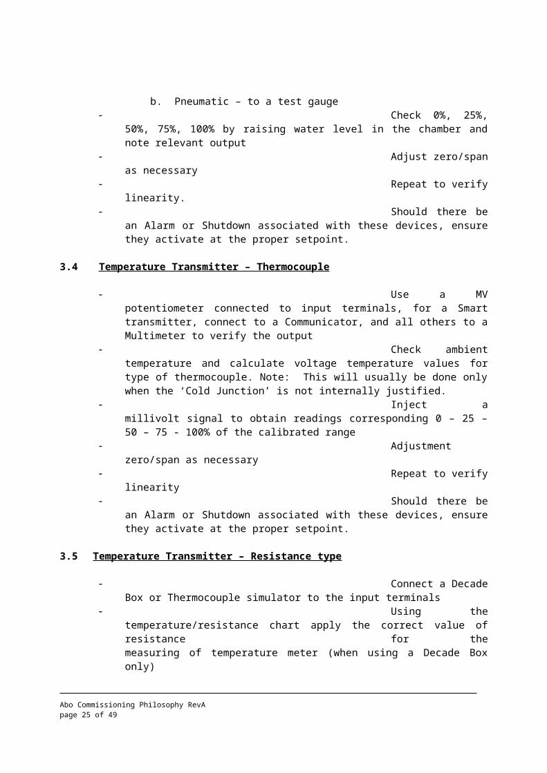
a. Electronic - to suitable Multimeter, but for a Smart Type connect to the Communicator. b. Pneumatic – to a test gauge
Check 0%, 25%, 50%, 75%, 100% by raising water level in the chamber and note relevant output
Adjust zero/span as necessary
Abo Commissioning Philosophy RevA page 18 of 37

Repeat to verify linearity.
Should there be an Alarm or Shutdown associated with these devices, ensure they activate at the proper setpoint.
3.4 Temperature Transmitter – Thermocouple
Use a MV potentiometer connected to input terminals, for a Smart transmitter, connect to a Communicator, and all others to a Multimeter to verify the output
Check ambient temperature and calculate voltage temperature values for type of thermocouple. Note: This will usually be done only when the ‘Cold Junction’ is not internally justified.
Inject a millivolt signal to obtain readings corresponding 0 – 25 – 50 – 75 - 100% of the calibrated range
Adjustment zero/span as necessary
Repeat to verify linearity
Should there be an Alarm or Shutdown associated with these devices, ensure they activate at the proper setpoint.
3.5 Temperature Transmitter – Resistance type
Connect a Decade Box or Thermocouple simulator to the input terminals
Using the temperature/resistance chart apply the correct value of resistance for the measuring of temperature meter (when using a Decade Box only)
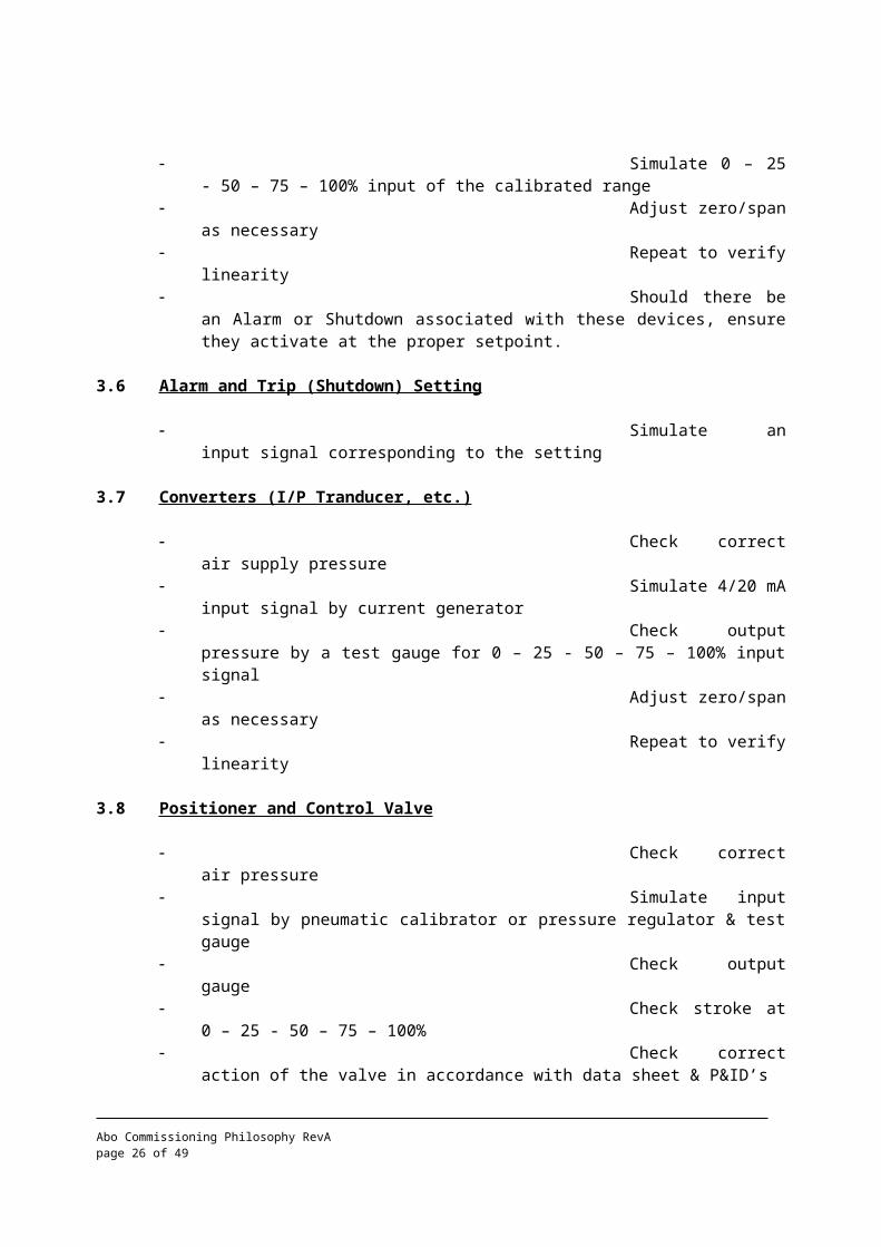
Simulate 0 – 25 - 50 – 75 – 100% input of the calibrated range
Adjust zero/span as necessary
Repeat to verify linearity
Should there be an Alarm or Shutdown associated with these devices, ensure they activate at the proper setpoint.
3.6 Alarm and Trip (Shutdown) Setting
Simulate an input signal corresponding to the setting
3.7 Converters (I/P Tranducer, etc.)
Check correct air supply pressure
Abo Commissioning Philosophy RevA page 19 of 37
Simulate 4/20 mA input signal by current generator
Check output pressure by a test gauge for 0 – 25 - 50 – 75 – 100% input signal
Adjust zero/span as necessary
Repeat to verify linearity
3.8 Positioner and Control Valve
Check correct air pressure
Simulate input signal by pneumatic calibrator or pressure regulator & test gauge
Check output gauge Check stroke at 0 –
25 - 50 – 75 – 100% Check correct action
of the valve in accordance with data sheet & P&ID’s Adjust zero/span as
necessary
3.9 Heat Detector
Simulate heat increase at head of the detector using a heat gun
Check output on monitor
Ensure that the audible alarm activates
3.10 Smoke Detector
Simulate smoke presence at the detector head
Check output on monitor
Ensure that the audible alarm activates
3.11 UV Detector
Use a light source to simulate a flame presence
Ensure that the audible alarm activates
3.12 Gas Detector
- Use reference gas to activate 10 – 20 – 50 & LEL- Ensure that the audible alarm activates
Abo Commissioning Philosophy RevA page 20 of 37
3.13 Analyzer
Check correct sampling hook-up. Verify installation conforms to vendors recommendations and that signal and earthing details are correct
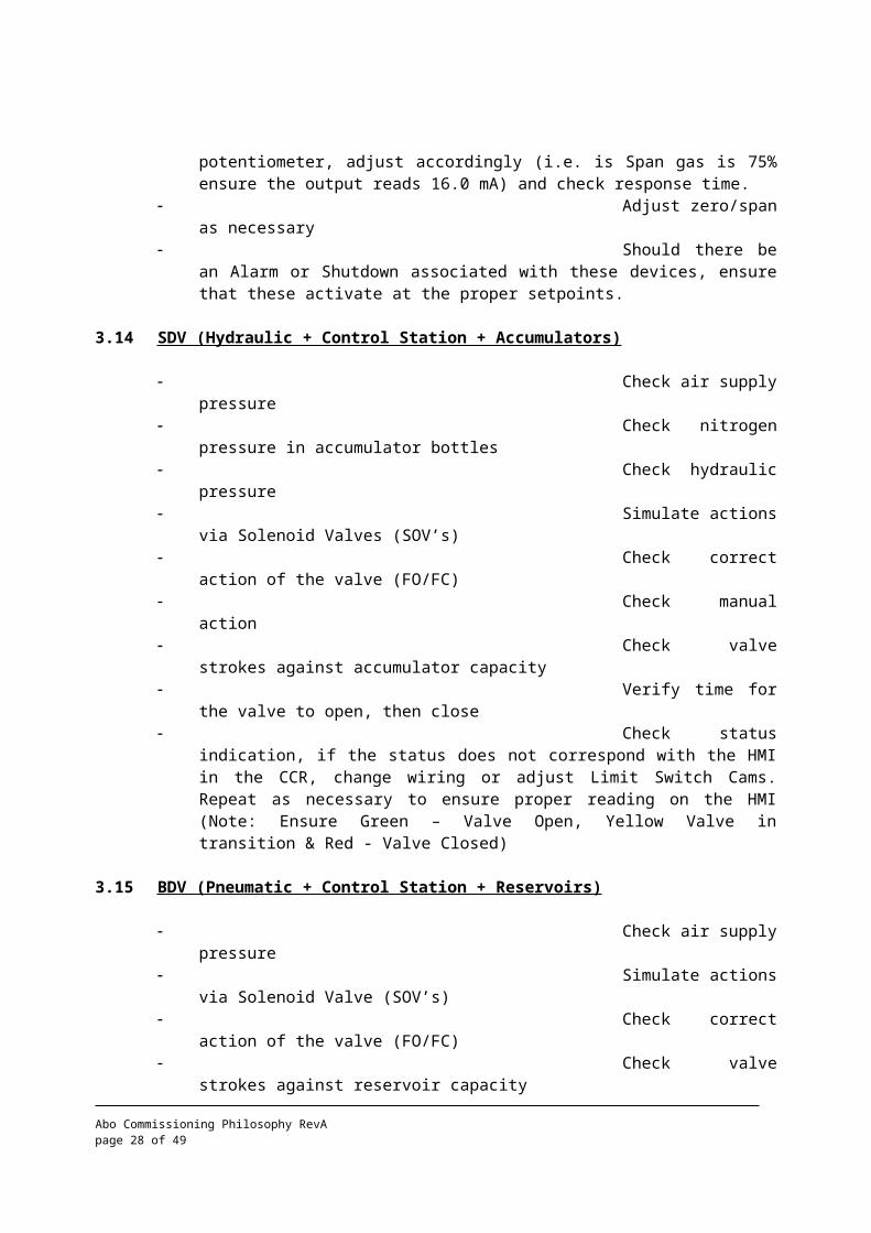
Check calibration with samples of Zero Gas, verify 4.0 mA output, then with Span gas, verify output, and with the Span potentiometer, adjust accordingly (i.e. is Span gas is 75% ensure the output reads 16.0 mA) and check response time.
Adjust zero/span as necessary
Should there be an Alarm or Shutdown associated with these devices, ensure that these activate at the proper setpoints.
3.14 SDV (Hydraulic + Control Station + Accumulators)
Check air supply pressure
Check nitrogen pressure in accumulator bottles
Check hydraulic pressure
Simulate actions via Solenoid Valves (SOV’s)
Check correct action of the valve (FO/FC)
Check manual action Check valve strokes
against accumulator capacity Verify time for the
valve to open, then close Check status
indication, if the status does not correspond with the HMI in the CCR, change wiring or adjust Limit Switch Cams. Repeat as necessary to ensure proper reading on the HMI (Note: Ensure Green – Valve Open, Yellow Valve in transition & Red - Valve Closed)
3.15 BDV (Pneumatic + Control Station + Reservoirs)
Check air supply pressure
Simulate actions via Solenoid Valve (SOV’s)
Check correct action of the valve (FO/FC)
Check valve strokes against reservoir capacity
Verify time for the valve to open, then close
Abo Commissioning Philosophy RevA page 21 of 37
Check status indication, if the status does not correspond with the HMI in the CCR, change the wiring or adjust Limit Switch Cams. Repeat as necessary to ensure proper reading on the HMI (Note: Ensure Green – Valve Open, Yellow – Valve in transition & Red – Valve Closed)
3.16 Instrument Functional Test Sheets
For each device installed, a functional test sheet will be provided and completed by the E&I Group. See Attachments
Abo Commissioning Philosophy RevA page 22 of 37

PRE-START UP ACTIVITIES
1 Introduction
Before undertaking the commissioning operational test and/or introducing feed into the plant, a number of specific process operations must be carried-out on the pipework and vessels, the so called ‘Pre-Start Up activities”.
These operations, the preparation and execution, are an integral part of the commissioning activities, and consists of the following:
Leak Test:
Leak tests are systematically performed on any sub-system involving pipework at maximum allowable operating pressure (MAOP).
Dry-out:
Removal of all water from the facilities, and is performed mainly on sections designed to work at low temperatures to avoid hydrates formation during the Process start-up phase.
Purging with Inert Gas:
To reduce the Oxygen content in Process systems to less than 2%, prior to the introduction of hydrocarbons to the Topsides.
2 Leak Tests
2.1 Introduction
Leak test should not be confused with piping pressure tests. The latter are carried out during pre-commissioning on pipe spools, to verify integrity of welding and material.
Leak tests are carried out on the entire subsystem, after Precom flushing and cleaning operations, and the mechanical completion of the subsystem, to prove integrity of the following:
Gaskets and other flanged joints, after Subsystem re-instatement Valve packing Connection between system being tested and inter-related systems Leak tests must also establish that any equipment previously dismantled for
whatever reason has been correctly reinstalled Leak test will also detect valves that are passing.
2.2 Test Specifications
Abo Commissioning Philosophy RevA page 23 of 37

2.2.1 Equipment to be leak tested
All piping, vessels, process and utility equipment, inclusive associated connections.Exceptions: Flare stacks, vents, heater casings, open drains, open-end piping down stream
of the control valves, and atmospheric tanks.
2.2.2 Leak test pressure
General rule: At maximum allowable operating pressure (MAOP)Exceptions: Pump suction lines will be tested at maximum suction pressure Systems protected by PSV’s will be tested at10% below the set point of the PSV.
2.2.3 Tightness criteria
General rule: Pressure fall of 0.05 bar/hr. or lessThe leak test will be complemented by a visual search of leaks by the soapy water method.
2.2.4 System test limits
The test boundary limits will be defined by the Commissioning Team utilizing marked-up P&ID’s.
The test limits will take into account the different levels of operating pressure within a subsystem. Should there be different pressures within a subsystem, isolate the different pressures, and test separately utilizing the maximum allowable operating pressure for the test.
2.3 Test Procedures General
The commissioning team will issue for each test a detailed procedure including marked-up PID’s or sketches showing test limits and valve isolations.
Step by step action list.
List of safety precautions.
Pressurization points: Normally a drain line, and when leak testing water systems the normal supply pressure may be used.
When each test is being performed, boundary tape and signs stating “Leak Test in Progress” will be placed around the test area to prevent the entrance of “Unauthorized Personnel”.
2.4 Low Pressure Leak Test
Systems with a maximum operating pressure of 10 barg or less, are normally tested using clean, de-oiled, dry compressed air. The test will be executed as follows:
Abo Commissioning Philosophy RevA page 24 of 37
Line-up the system to be tested, all instrument lines open, drain and vent valves closed, etc.
Connect a flexible hose from Air Compressor to air injection point. (drain valve)
Pressurize the system slowly to its maximum allowable operating pressure, then close injection point valve.
Record pressure and start the clockwork pressure recorder, and note the time.
Commence checking flanges, valve packing glands, vents and drains for leaks using a soap solution (Snoop or similar) Any leaks found to be repaired immediately, and the test re-commenced
If no leaks, continue test for 2 hours.
Upon successful completion, depressurize the system via convenient vent valve, close vent valve, and remove hose from drain valve. Complete paperwork.
2.5 High Pressure Leak Test
Process systems with an operating pressure in excess of 10 barg are normally tested with Nitrogen, or a N2He mix. The test will be executed as follows:
Line-up the system to be tested, all instrument lines open, drain and vent valves closed, etc.
Carry out gross air leak test to 6 barg to identify any excessively bad leaks. If no leaks, de-pressurize and connect N2He injection hose to drain valve.
Start injecting N2He in steps of 25% test pressure, for safety reasons. Check system for leaks at each step, then re-commence injection up to 100% test pressure.
Commence checking flanges, valve packing glands, vents and drains for leaks using a soap solution. Any leaks found are to be repaired immediately.
If no leaks are apparent, note the time. Start the clockwork pressure recorder. Continue test for 2 hours.
Should test fail, de-pressurize system, tighten applicable flanges, screwed fittings, valve packing glands, etc. Repeat test as necessary to satisfy test criteria.
Upon successful completion, reduce the system pressure, via convenient vent valve, to 2 barg, leaving a positive inert gas blanket trapped within the system, ready for Process start-up. Complete the paperwork with signatures from all relevant parties witnessing the test.
2.6 Atmospheric Vessels
Abo Commissioning Philosophy RevA page 25 of 37
Fill the vessel to its maximum level and observe for leaks.
Complete the Leak Test Report
Drain water to prevent any future operation problems. It may be necessary to perform a drying-out operation to prevent hydrates from forming in process equipment, or to minimize corrosion.
Dry-out operations are a part of the commissioning team’s activity.
3 Dry-Out
3.1 Introduction
Upon completion of water flushing, water will be present in process equipment and this water will have to be drained, and a Drying-Out process will have to be performed.
3.2 Dry-out Specifications
The procedure will be defined according to special field conditions and requirements (dew point control, dry air/nitrogen sweeping or purging).
Abo Commissioning Philosophy RevA page 26 of 37

OPERATIONAL TESTS
1 Introduction
1.1 Purpose
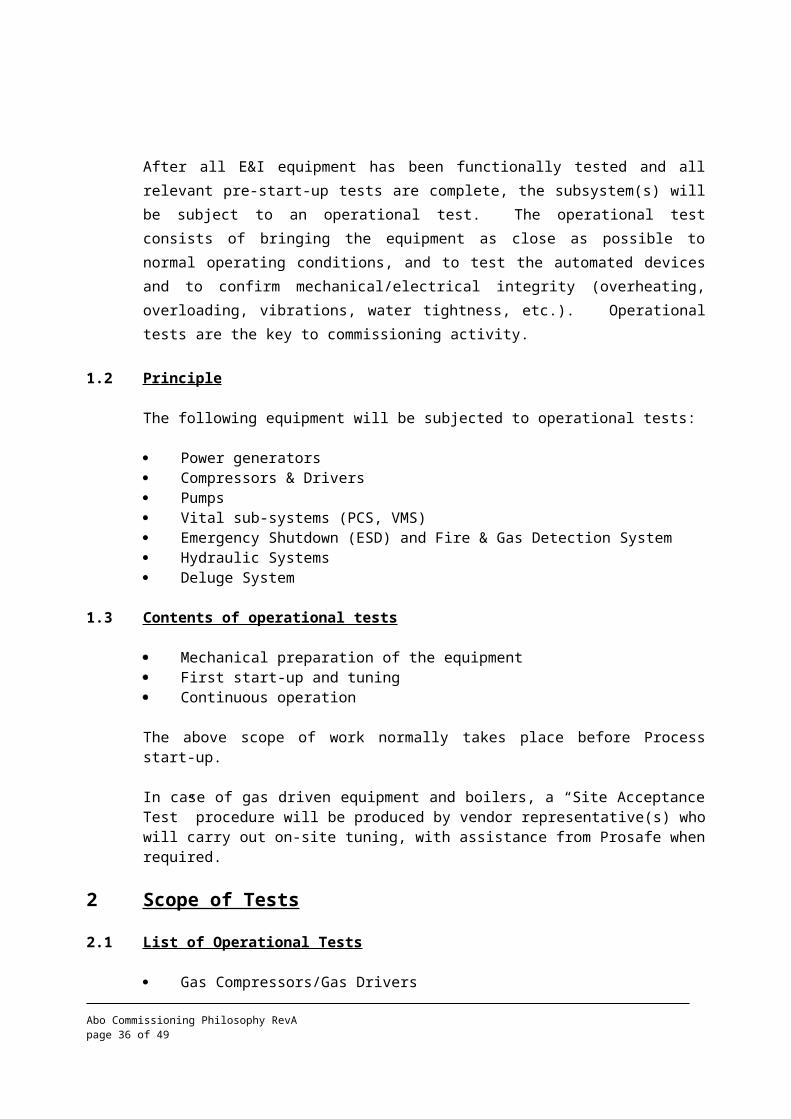
After all E&I equipment has been functionally tested and all relevant pre-start-up tests are complete, the subsystem(s) will be subject to an operational test. The operational test consists of bringing the equipment as close as possible to normal operating conditions, and to test the automated devices and to confirm mechanical/electrical integrity (overheating, overloading, vibrations, water tightness, etc.). Operational tests are the key to commissioning activity.
1.2 Principle
The following equipment will be subjected to operational tests:
Power generators Compressors & Drivers Pumps Vital sub-systems (PCS, VMS) Emergency Shutdown (ESD) and Fire & Gas Detection System Hydraulic Systems Deluge System
1.3 Contents of operational tests
Mechanical preparation of the equipment First start-up and tuning Continuous operation
The above scope of work normally takes place before Process start-up.
In case of gas driven equipment and boilers, a “Site Acceptance Test” procedure will be produced by vendor representative(s) who will carry out on-site tuning, with assistance from Prosafe when required.
2 Scope of Tests
2.1 List of Operational Tests
Gas Compressors/Gas Drivers Air Compressors/Filters/Dryers Hydraulic Units Air Conditioning Units and Ventilation Systems Water Makers and Loops Cranes Inert Gas Unit Marine Growth Prevention Package
Abo Commissioning Philosophy RevA page 27 of 37
Cathodic Protection Package/System Cooling Water Pumps and System Fire Water & Jockey Pumps and System Water Injection System Dew Point Control System Vacuum System Chemical injection System(s) Deluge System UPS System Main Power and Emergency Generators Power Distribution Control Life Boat and Davits Communication Systems Glycol Regeneration System ESD System Control System Boilers/Low Pressure Steam Generation (LPSG) and Steam Generation System Diesel Oil Fuel Gas System Produced Water System Drain and Bilge System Fire Fighting and Foam Systems Total Flooding System Domestic Refrigerator System Cargo Pumps and Loading/Offloading System Mooring System Crude Oil Metering Skid/System Ballast Pumps and Ballast Network F&G Detection System
2.2 Operational Test of Process and Utilities
The operational test consist of 3 phases:
Test preparation Tuning Operational demonstration
2.2.1 Test Preparation
Mechanical preparation
The mechanical preparation of rotation equipment of the system will be the first task of the operational test and address points as below:
Visual inspection Cleanliness Removal of preservation Freedom of rotation Final alignment checks Lubrication Lube, seal and hydraulic oil filling
Abo Commissioning Philosophy RevA page 28 of 37

Coupling of driver Loading of chemicals Filters and cartridge inspection Running and verification of auxiliaries and utilities Cranking test Mechanical preparation check lists will be made available
2.2.2 Start-up and Tuning
Once the subsystem is ready for its first start-up, this will be achieved by following a step by step procedure normally available from the manufacturer, should none be available by the time of testing, a procedure will be written by the Commissioning Team Leader or one of his designates. Before each system is ready for “Operational Testing”, the Commissioning Team must allow time for tuning and debugging.
2.2.3 Operational Demonstration
The operational demonstration will include the following verifications:
Normal cold/start/stop/Emergency Shutdown sequence Depressurization Automatic/Hand Mode Starts Air/Motor/Battery/Hydraulic Starters Duty/Stand By/Local/Remote Modes Synchronization Verify Control System Pressure/Speed/Level/Flow and Temperature Control Data Gathering Remote/Local Controls For Generators running in parallel: Load Sharing Verification that the mechanical systems is sound:
Noise/vibrations Coolant/Lube Oil/Flow, Temperature and Pressure monitoring
Verification survey of: Seals integrity Fuel and Oil leaks Piping vibrations Strainers and Filters D/P Oil consumption Signs of mechanical wear Hot Alignment and Final Inspection
Verification of Equipment Performance: Process and Electrical readings at several loads Plotting actual performance against theoretical characteristics Verification of trip functions HH/LL T/P/L ESD/PSD Overspeed
Abo Commissioning Philosophy RevA page 29 of 37

NOTE:Only critical protection will be tested with actual shutdowns, all other protection will be tested with trip action by-passed.
2.3 Operational Tests of ESD and Fire&Gas Detection Systems
2.3.1 System architecture
ESD/ F&G systems can be technically divided into:
Input loops, Logics unit (PLC or relays), Output loops.
The configuration of the system, the logic part of it essentially, is specific to the installation. The main configuration cases are:
Master/Slave, Coincidence, Two of three voting system.
ESD systems are designed so that they include a hierarchy of effects. Assuming the highest ESD level (total plant shutdown and depressurization) is named level 1, each of levels 2 and 3 will affect less equipment than the respective higher levels.
These systems most often apply a cascade principle, where each level will activate lower levels in addition to its specific outputs.
2.3.1 System test
Each input and output loop and the system logics will have been tested during the functional test phase of the commissioning. The ESD and F&G operational tests will consist in testing the whole system, from the input elements (transmitter, detector, push button etc.) until the activated equipment (ESD Valve, Blowdown Valve, Motor Trip, Compressor Shutdown, etc.).
Considering the system architecture, these operational tests will be organized as follows:
2.3.1.1 ESD Systems
The shutdown levels will be tested, starting at the lowest level, to end at the highest one.
For each category of inputs that give identical effects, one input will be selected at random, and the shutdown will be initiated. It will then be verified that all expected outputs of this shutdown level thus triggered have been activated and that the connected equipment has performed as expected.
Abo Commissioning Philosophy RevA page 30 of 37

The other input of this category will also be tested systematically but without resetting all equipment that was operated by the previous test. It will only be made sure that at least one output from each lower shutdown activated by the tested shutdown level has actually been activated.
As the ESD tests will be performed before the plant start up it will be impossible to check the action on non running equipment i.e., electrical motors. In this case one will make sure that the trip element of the equipment concerned is activated i.e., Auxiliary Contactors for electrical motors.
If an ESD is necessary with the plant in operation, it will be performed after handover, and the Prosafe operations personnel will be in charge of the test.
All categories of inputs will be tested in the same way, thus ensuring the proper functioning of all inputs and outputs, and of the shutdown logics in all its possible configurations.
The reference document will be ESD Matrix Logic Diagram and the ESD/F&G Cause and Effect Chart.
2.3.1.2 F&G Systems
The procedure applied to test operationally the F&G systems will be exactly that used for ESD, but for the following points:
Detectors being grouped by loops, only one detector in a loop will be selected at random to initiate a given range of actions (then for each category of loops giving the same effects, one detector will be tested), the other simulated, as for ESD).
CO2 will not be actually released, the test consisting only in activating the last solenoid valve. The solenoid valves will be removed from the CO2 bottles at the time of testing.
The deluge valves will be activated, the fire pumps started and the deluges actually released, but the two latter effects only once. The FPSO facilities will therefore be systematically deluged once, the continuing tests also activating the deluge valves, but with the block valves closed.
The reference document will be the F&G Matrix Logic Diagram and the ESD/F&G Cause and Effect Chart.
ADDITIONAL ACTIVITIES
1 Support Activities
Abo Commissioning Philosophy RevA page 31 of 37

Depending on contractual clauses the Commissioning Team will perform, organize or follow-up the following:
Materials : Spares, consumables, test equipment and documentation. Depending on contractual clauses between Operator and the Sub Contractor(s)
Personnel: Mobilization, organization and administration. Depending on contractual clauses between Operator and the Sub Contractor(s)
Vendors: Mobilization and assistance depending on contractual clauses between Operator and the Sub Contractor(s)
` Planning:
Commissioning Forecasts and programs will be produced and updated by the Operator Planner/ Scheduler to incorporate input from Project Team and the Commissioning team, schedule will be communicated with the Commissioning team prior to execution
Punch List: The ABO Commissioning Team Punch list Coordinator will compile Punch lists of Topside Facilities, Power Generation and Distributions and Utilities during the Installation and Project Completion Stage. The Outstanding Punchlist items must be cleared prior to Process Start-up.
2 Documentation Tasks
2.1 Technical Data Base
Update: PID’s, Single Line Diagrams, ESD/F&G Matrixes.P&ID compilation checks will be performed
2.2 Punch List
Punchlists, as agreed, at the ready for commissioning stage, will be continuously updated by adding newly discovered items, items that have been rectified will be dated and signed off by relevant parties.
At the time of “Ready for Hand-over”, additional, genuine items discovered by the operator will be included in the punch list.
2.3 Drawings Up-dating
PFD / PID’s Cause and Effect Diagrams Single Line Diagrams ESD/F&G matrixes Termination Drawings
Abo Commissioning Philosophy RevA page 32 of 37

Electrical Schematics Instrument Loop Diagrams Vendor Drawings and Details
2.4 Filing of Commissioning activities
The commissioning files generally follow the main system group index of the Tagging procedure. (Engineering Doc. 255-DOC-091) Some large groups will be further sub-divided into Subsystems, for ease of management of the files, in cases such as Group 20 Separation and Stablization.
The Index of the filing system is:
1. Drawings and P&ID’s2. Register and Tagging 3. Commissioning preparations/Preliminary activities 4. Commissioning activities/functional test sheets5 Pre-Start up checks6. Operational tests7. Commissioning punch list8. Certificates
After completion/signing over an activity, the Commissioning Engineers will give the signed off sheets to the Technical Administrator, who will liaise with the Commissioning Coordinator.The technical administrator is responsible for correct filing of all the documents.
2.5 Hand-over Dossier
The commissioning team will compile all documentation pertaining to the commissioning operations in a specific hand-over dossier, arranged by sub-system, which will contain all the information required to demonstrate to the Operator that the system has reached the “Ready for Hand-Over” status.
The dossier will include the following:
1. Hand-over certificate
2. Subsystem definition drawings
3. Commissioning Database print-out
4. Preliminary checks reports
5. Functional test sheets
6. Operational test procedure
7. Mechanical reports
8. Hand-over punch list
Abo Commissioning Philosophy RevA page 33 of 37

9. As-built drawings
10. List of modifications
APPENDIX A
Pre-commissioning witnessing check sheets:
1. PCW-01 Pre-commissioning witnessing
2. PC-O-01 Pre-commissioning piping
Abo Commissioning Philosophy RevA page 34 of 37

3. PC-O-02 Pre-commissioning vessel
4. PC-M-01 Pre-commissioning rotating equipment
5, PC-E-01 Pre-commissioning electrical
6. PC-E/I-01 Pre-commissioning instrument
7 Miscellaneous check sheets from package supplier
APPENDIX B
Instrument functional test sheets:
1. IFT-01 Process control loop check
2. IFT-01a Process control loop check
Abo Commissioning Philosophy RevA page 35 of 37
3. IFT-01b Process control loop check
4. IFT-01c Process control loop check
5. IFT-2 Digital loop check
6. IFT-2a Digital loop check
7. IFT-3 Digital loop check F & G
8. IFT-3a Digital loop check F & G
9. IFT-4 Analogue loop check
10. IFT-4a Analogue loop check
11. IFT-5 Analogue loop check F & G
12. IFT-6 Instrumentation – PSD-24 VDC
13. IFT-7 Instrumentation data communication
14. IFT-8 Instrumentation F & G logic
15. IFT-9 Instrumentation Relief valves
16. Miscellaneous test sheets from package suppliers
APPENDIX C
Electrical functional test sheets:
1. EFT-1 HV Generator
2. EFT-1a LV Generator
Abo Commissioning Philosophy RevA page 36 of 37

3. EFT-2 UPS System
4. EFT-3 Battery
5. EFT-4 HV Switchboard
6. EFT-4a LV Switchboard
7. EFT-5 HV Transformer
8. EFT-6 Distribution board
9. EFT-7 Elec. Motors
10. EFT-8 Navigational Aids
11. EFT-9 Misc. users
12. EFT-10 Lighting & Small Power
13. EFT-11 Elec. Motors run-in
14. EFT-12 Megger Rotating & Non-Rotating Equipment
15. EFT-13 Megger Power & Control wires/cables
16. EFT-14 Wire/Cable Installation/Termination
17. EFT-15 Electrical Generator function test
18. EFT-16 Electrical lighting function test
19. EFT-17 Electrical Battery functional test
20. EFT-18 Electrical Fuse functional test
21 EFT-19 Electrical LV Protection relays
22 Miscellaneous test sheets from package suppliers
Abo Commissioning Philosophy RevA page 37 of 37


![COPYRIGHT AND CITATION CONSIDERATIONS FOR … · M.A. (Philosophy)/M.Com. (Finance) etc. [Unpublished]: ... installation, commissioning and operating a batch pyrolysis plant in](https://img.dokumen.tips/doc/110x75/5b18fec97f8b9a32258c3f29/copyright-and-citation-considerations-for-ma-philosophymcom-finance.jpg)