Embed Size (px)
Citation preview

Commission o f t h e European Communities
ear scienc and technology
The Community's research and development programme
on decommissioning of nuclear installations Second annual progress report (year 1986)

M s u<j.b
Commission of the European Communities
$ C I *.']& w iesäfe
*W< ^ ^ F ' '¿saÇ'" ' ■** V¿ ¥í* **%£»* èfe '^Sw**
The Community's research and development programme
on decommissioning of nuclear installations Second annual progress report (year 1986)
Directorate-General Science, Research and Development
1 ^ v,n°i IP
1987 PAR r y E Ü H 11112 EN N.C./EUR CL tè>* a ( ' <; j A A

Published by the COMMISSION OF THE EUROPEAN COMMUNITIES
Directorate-General Telecommunications, Information Industries and Innovation
Bâtiment Jean Monnet LUXEMBOURG
LEGAL NOTICE Neither the Commission of the European Communities nor any person acting on behalf of the Commission is responsible for the use which might be made of the
following information
Cataloguing data can be found at the end of this publication
Luxembourg: Office for Official Publications of the European Communities, 1987
ISBN 92-825-7385-0 Catalogue number: CD-NA-11112-EN-C
© ECSC-EEC-EAEC, Brussels • Luxembourg, 1987
Printed in Belgium

FOREWORD
This is the second Annual Progress Report of the European Community's 1984-88 programme of research on the decommissioning of nuclear installations. Tt covers the year 1986 and follows the 1985 Report /l/.
The Council of the European Communities adopted the programme in January 1984 111, considering: "Certain parts of nuclear installations inevitably become radioactive during operation; it is therefore essential to find effective solutions which are capable of ensuring the safety and protection of both mankind and the environment against the potential hazards involved in the decommissioning of these installations".
Also, the Council recognized that the 1979-83 programme of research on the decommissioning of nuclear power plants, of which the current programme is a follow-up, "has yielded positive results and opened up encouraging prospects". The main publications relating to the results of this first programme are listed in Annex I.
The 1984-88 programme has the following contents:
A. Research and development projects concerning the following subjects: Project N° 1: Long-term integrity of building and systems; Project N° 2: Decontamination for decommissioning purposes; Project N° 3: Dismantling techniques; Project N° 4: Treatment of specific waste materials: steel, concrete
and graphite; Project N° 5: Large containers for radioactive waste produced in the
dismantling of nuclear installations; Project N° 6: Estimation of the quantities of radioactive wastes
arising from the decommissioning of nuclear installations in the Community;
Project N° 7: Influence of installation design features on decommissioning.
B. Identification of guiding principles, namely: - certain guiding principles in the design and operation of nuclear installations with a view to simplifying their subsequent decommissioning,
- guiding principles in the decommissioning of nuclear installations which could form the initial elements of a Community policv in this field.
C. Testing of new techniques under real conditions, within the framework of large-scale decommissioning operations undertaken in Member States.
The research is carried out by public organisations and private firms in the Community under cost-sharing contracts with the Commission of the European Communities. The Commission budget planned for this five-year programme amounts to 12.1 million ECU.
The Commission is responsible for managing the programme and is assisted in this task by the Management and Coordination Advisory Committee "Nuclear fission energy - Fuel cycle/processing and storage of waste" (see Annex II).
The subject of this report is formed by 58 research contracts, including 31 new contracts concluded in 1986 as well as 4 contracts of which the execution has been completed in 1986. Besides, 11 contracts were still at the stage of negotiation at the end of the year.

The present report describes the objectives, scope and work programme of each research contract concluded, as well as the progress of work achieved and the results obtained in 1986.
For each contract, the Paragraph "C. Progress of Work and Obtained Results" has been prepared by the contractor, under the responsibility of the Project Leader. The Commission wishes to express its gratitude to all scientists of the contractors who have contributed to this report.
The Commission staff having edited the report are: E. Skupinski, R. Risei and K. Pflugrad.
B. Huber Head of the Programme
References /l/"The Community's research and development programme on decommission
ing of nuclear installations. First annual progress report (vear 1985)". EUR 10740, 1986.
HI Council Decision of 31 January 1984 adopting a research programme concerning the decommissioning of nuclear installations. OJ N° L 36, 8.2.1984, p. 23.
- IV

CONTENTS
Page
1. PROJECT N° 1: LONG-TERM INTEGRITY OF BUILDINGS AND SYSTEMS 1 1.1. Long-term stability and leak tightness of reactor
containments 2
2. PROJECT N° 2: DECONTAMINATION FOR DECOMMISSIONING PURPOSES 7 2.1. Complete decontamination of a primary steam piping of the
Lingen BWR 8 2.2. Aggressive chemical decontamination tests on valves from the
Garigliano BWR 10 2.3. Decontamination using chemical gels, electrolytical swab and
jet, abrasives 16 2.4. Development of an easy-to-process electrolyte for decontami
nation by electropolishing 19 2.5. Optimization of filtering systems for various concrete
decontamination techniques 23 2.6. Economic comparison of decontamination and direct melting
with a view to recycling of scrap 28 2.7. Remote electrochemical decontamination for hot cell
applications 30 2.8. Decontamination with pasty pickling agents forming a
strippable foil 36 2.9. Rack-torch unit for remote decontamination of concrete 40 2.10. Feasibility of concrete decontamination using a plasma-
augmented burner 41
3. PROJECT N° 3 : DISMANTLING TECHNIQUES 42 3.1. Ventilation and filtration techniques for thermal cutting
operations 43 3.2. Prefiltering devices for gaseous effluents from dismantling
operations 50 3.3. Dross and ultrafine particulate formation in underwater
plasma-arc cutting 57 3.4. In-situ arc-saw cutting of heat exchanger tubes and of pipes
from the inside 63 3.5. Electrochemical technique for the segmenting of activated
steel components 69 3.6. Explosive techniques for the dismantling of biological
shield structures , 74 3.7. Explosive techniques for dismantling of activated concrete
structures 80 3.8. Prototype system for remote laser cutting of radioactive
structures 85 3.9. Investigations of applications of laser cutting in
decommissioning 92 3.10. Spreading and filtering of radioactive by-products of under
water segmenting 96 3.11. Development of a prototype system for remote underwater
plasma-arc cutting 101 3.12. Remote measuring and control systems for underwater cutting
of radioactive components 106 3.13. Removal of concrete layers from biological shields by
microwaves Ill
- V

3.IA. Adaptation of an existing air-tight and modular workshop for remote operation 115
4. PROJECT N° 4: TREATMENT OF SPECIFIC WASTE MATERIALS: STEEL, CONCRETE AND GRAPHITE 121 4.1. MeIting/refining of contaminated steel scrap from
decommissioning 122 4.2. Melting of radioactive metal scrap from nuclear
installations 124 4.3. Separation of stainless steel constituents using transport
in the vapour phase 129 4.4. Immobilisation of contamination of large waste units by
polymer coating 135 4.5. Investigations into the melting of radioactive metal waste
in a controlled area 137 4.6. Behaviour of actinides and other radionuclides that are
difficult to measure, in melting of steel 139 4.7. Conditioning and disposal of radioactive graphite bricks
from reactor decommissioning 140
5. PROJECT N° 5: LARGE TRANSPORT CONTAINERS FOR RADIOACTIVE WASTE PRODUCED IN THE DISMANTLING OF NUCLEAR INSTALLATIONS 141 5.1. Design and evaluation of large containers for reactor
decommissioning waste 142 5.2. Large waste containers made of fibre-reinforced cement 146 5.3. Large waste containers cast of low-level radioactive metal
scrap 149
6. PROJECT N° 6: ESTIMATION OF THE OUANTITIES OF RADIOACTIVE WASTE ARISING FROM THE DECOMMISSIONING OF NUCLEAR INSTALLATIONS IN THE COMMUNITY 154 6.1. The assessment of low-level contamination from gamma-emit
ting radionuclides 155 6.2. Development of methods to establish the curie content of
radioactive waste from decommissioning 159 6.3. Systems for contamination measurements on curved surfaces...160 6.4. Optimisation of measurement techniques for very low-level
radioactive material 162 6.5. Monitoring gamma radioactivity over large land areas using
portable equipment 164 6.6. Radioactive wastes arising from the dismantling of a
commercial Fast Breeder Reactor 166 6.7. Radiological evaluation of releasing very low-level
radioactive copper and aluminium 167
7. PROJECT N° 7: INFLUENCE OF NUCLEAR INSTALLATION DESIGN FEATURES ON DECOMMISSIONING 169 7.1. Decontamination and remote dismantling tests in the ITREC
reprocessing pilot plant 170 7.2. Testing of cobalt-free valve seatings using a special test
loop 175 7.3. In-situ sealing of concrete surface by organic impregnation
and polymerisation 179 7.4. Influence of design features on decommissioning of a large
Fast Breeder Reactor 183
- VI -

8. SECTION C: TESTING CF NEW TECHNIQUES UNPEP PEAL CONDITIONS 184 8.1. Dismantling and decontamination of a feedwater preheater
tube bundle of Garigliaro BWR 185 8.2. Conditioning, transport and dismantling of very large
plutonium glove-boxes 191 8.3. Large-scale application of segmenting and decontamination
techniques 196 8.4. Development of techniques to dispose of the Vindscale AGR
heat exchangers 203 8.5. Pilot decommissioning of a mixed-oxide fuel fabrication
facility 210 8.6. Testing of new techniaues in decommissioning of a fuel
(U, Th) fabrication plant 217 8.7. Decontamination and dismantling of the PTVER prototype
vitrification facility 223 8.8. Dismantling, partly in-situ, of a glove-box structure of a
mixed-oxide fuel plant 229 8.9. Melting of radioactive metal scrap from the KRB-A plant ....235 8.10. Volume and plutonium inventories before and after disman
tling of a mixed-oxide fuel plant 237 8.11. Decontamination, before dismantling, of the primary coolant
system of the RAPSODIE FBR 242 8.12. Automated measuring system for waste from dismantling of
the KKN plant, to be released 248
X X
X
ANNEX I LIST OF PUBLICATIONS RELATING TO THE RESULTS OF THE 1979-83 PROGRAMME ON THE DECOMMISSIONING OF NUCLEAR POWER PLANTS 254
ANNEX II MEMBERS OF THE MANAGEMENT AND COORDINATION ADVISORY COMMITTEE "NUCLEAR FISSION ENERGY - FUEL CYCLE/PROCESSING AND STORAGF OF WASTE" 257
- VII


1. PROJECT N°l: LONG-TERM INTEGRITY OF BUILDINGS AND SYSTEMS
A. Objective
It has been proposed that the dismantling of nuclear installations be delayed for periods ranging from several decades to about a hundred years. Thereupon, the radioactivity having largely died away, dismantling would be easier and the radiation exposure of the dismantling personnel would be less. The objective of this project is to determine the measures required for maintaining shut-down plants in a safe condition and to assess the radiological consequences and costs.
P. Research performed under the 1979-83 programme
The work performed under the previous programme relates mainly to the following aspects: - mode and pace of degradation of various materials as they exist in
nuclear power plants; - measures for maintaining plants in a safe condition and for keeping
the necessary ancillary systems operable; - monitoring and inspection procedures ; - radiological consequences and costs of maintaining the plants.
C. 1984-88 programme
The work performed under the first five-year programme should be complemented by further tests and the study of control methods relating to the aging of relevant plant materials and by exploitation of additional experience with shut-down nuclear installations.
D. Programme implementation
One research contract relating to Project N°l has been concluded in 1986 and two more contracts were still at the stage of negotiation at the end of the year.

1.1. Long-term Stability and Leak Tightness of Peactor Containments
Contractor: Zerna, Schnellenbach und Partner GmbH, Bochum, Germany. Contract N": FI1D-0031 Working Period: April 1986 - June 1988 Project Leader: R. Oberpichler
A. Objectives and Scope The objective of this research is to study the long-term performance
of structures comprising nuclear power plants. The time period of interest for this study is 140 years, account being taken of maximum periods of 40 years for operation and 100 years of storage. Particular attention will be given to those parts of the plant for which leak tightness and structural integrity are required, both during operation and for long periods after final shutdown.
The specific aim of this research is to investigate the behaviour of complex composite structures, taking as a basis the long-term behaviour of materials. The possible susceptibility to long-term damage will also be assessed, and the areas most prone to such damage will be identified. Further consideration will be given to the possible interaction between sealing steel components (steel containments, steel liners) and load bearing concrete structures.
This building survey will be carried out on structural elements of actual PWR stations (e.g. Emsland-Lingen) and BWR stations (e.g. Gundrem-mingen B and C). Consideration will be given to the validity of the investigations for relevant structures of other commercial nuclear power plants in the European Community. This investigation will include the shut-down BWR station of Garigliano in Italy.
B. Work Programme B.1. Investigation on reinforced concrete and prestressed concrete
structures. B.l.l. Selection of structural elements considered important with regard
to the integrity of long-term containment. B.1.2. Literature study on material behaviour covering long-term proper
ties. B.1.3. Analysis of the long-term behaviour of the selected structural
elements. B.2. Investigation of steel containments B.2.1. Selection of elements susceptible to damage, in particular plastic
sealings with concrete and steel. B.2.2. Assessment of damage (state of material, types of corrosion,
formation of condensed moisture, permeability of the concrete, etc.)
B.2.3. Optimization of ultrasonic testing techniques (angular sound, weakening, creep wave, etc.) and application of the selected techniques to decommissioned Niederaichbach and Gundremmingen I nuclear power plants.
B.3. Recommendations for monitoring and enhancing long-term integrity of reinforced and prestressed concrete and for assessment of in-situ corrosion of steel elements.

C. Progress of work and obtained results Summary
During the f i r s t reporting period the following parts of the work programme have been worked on: - specification of concrete structural elements which are considered
important to the long-term s tab i l i t y ( B . l . l ) ; - l i terature studies on long-term material behaviour concerning the pro
perties of concrete, reinforcing steel and prestressing steel (B.1.2); - studies on type of corrosion mechanisms, corrosion areas and corro
sion rates concerning the steel containments (B.2.1, B.2.2).
Progress and results T. Specification of the main concrete structural elements ( B . l . l . )
Aim of this working step was getting knowledge about the function of the structural elements of the referred power plants concerning thei r bearing behaviour and hence about their importance due to the long-term s tab i l i t y of the entire reactor buildings. Those structural elements are named and proposed for analysing in the following working period. In Fig. 1 a section of a PWR-station and in Fig. 2 a section of a BWR-station are shown. The hatched parts are mainly responsible for the long-term s tab i l i t y of the reactor buildings. Especially the primary and secondary containments including the support ing structures, the biological shield and some special wall elements are proposed for investigations in working step B.1.3.
2. Literature studies on material behaviour of concrete and reinforcing steel (B.1.2.) The l i terature studies on material behaviour are devided into three
parts: - properties of concrete - properties of reinforcing and prestressing steel and - properties of the composite material consisting of steel and con
crete . Several conclusions can be given from the literature studies for later analysing the main structural elements of a reactor building: - The strength of concrete is not expected to decrease during the time
of 100 years after decommissioning. - The carbonation depth is not expected to exceed about 20 mm on an ave
rage within the regarded period of time. Only under worst environmental and concrete quality conditions the carbonation depth has reached about 70 mm.
- According to the kind of aggression concrete corrosion is devided into three areas: - physical - physical-chemical - chemical and - microbiological.
- The chemical corrosion of concrete requires aggressive agents which are not l i ke ly to occur in a decommissioned nuclear power plant.
- Deteriorations of concrete by radiation require high values of fluence and a high y-radiation dose which are not expected in the period after decommissioning.
- The steel corrosion were categorized into three areas: chemical corrosion, electrochemical corrosion and cracking due to stress corrosion or hydrogen embrittlement.

- As the most observed corrosion type the electrochemical corrosion of reinforcing steel may only occur in those parts of the concrete structures where the steel depassi vates in consequence of concrete carbonati on or high concentration of chloride ions.
- The environmental conditions have to be taken into consideration very carefully, because in particular the grade of humidity, its frequent changings during lifetime, the concentration of carbon dioxide or chloride, the pollution of air and water by sour agents and the temperature are of great influence on the durability of concrete and steel.
The durability depends mainly on the grade of carbonation of the concrete effecting the loss of its alcaline properties, on concrete corrosion and on steel corrosion of the embedded steel.
Although the durability of concrete is known by tests for a period less than about 50 years the development of the material properties for a period of about 100, respectively 140 years, can be estimated with some approach to accuracy. Nevertheless methods of monitoring the actual state of the composite elements for each time are to be proposed in the following working step to provide security for unexpected environmental conditions. 3. Investigations on steel containments (B.2.1, B.2.2.)
During the third research project concerning the steel containments an attempt was made to look into the following: - type of corrosion mechanisms assumed, - areas of the container requiring special attention, - observation of the corrosion rates to be assumed. First conclusions can be drawn from these results for carrying out recurrent tests.
Recently, elastic plastics have mainly been used to seal steel components from structures of reinforced concrete.
The aim of these tests is to create a basis for sensible extrapolation of the long-term behaviour of sealed joint constructions of this kind, taking account of the conditions in which they are used.
Test plates of the same material and dimensions of comparable reactor containments were procured for ultrasonic tests and prepared for the introduction of test defects.

+54,4 m
% ± 0,0 m
v- 6,0 m VAWAVAV
UJA inner rooms UJB surrounding rooms U-JE steam and feed water valve compartment 1 steel reactor pressure vessel 2 b i o l o g i c a l s h i e l d 3 calotte shell 4 circle wall 5 foundation plate 6 reactor building crane 7 steel containment (primary containment) 8 reinforced concrete containment
(secondary containment)
Fiq. 1 Section of the PWR-Station Reactor Building Ems land (KKE)

v +60,4 m
- 9
1 steel reactor pressure vessel 2 bi ologi c?1 shield 3 'irestressec; concrete containment (primary containi'icnt) 4 condensation room 5 steel liner 6 fuel assemblies deposit basin 7 surrounding rooms 8 reactor building crane 9 reinforced concrete containment (secondary containment) 10 pressure room
Fi_g._2 Section of the_ BWP-Station Reactor Buildina Gundremmingen H (KRB II)
2. PROJECT N°2: DECONTAMINATION FOR DECOMMISSIONING PURPOSES
A. Objective
The objective of this project is to develop and assess techniques for decontaminating surfaces of components and structures of nuclear installations that are past use. The main purpose of decontamination would be reduction of the occupational radiation exposure during dismantling of the contaminated item and/or reduction of the volume of radioactive waste.
B. Research performed under the 1979-83 programme
The following decontamination techniques have been developed and assessed: - techniques based on the use of chemically aggressive decontaminants in
liquid and gel-like form; - electrochemical techniques; - hydromechanical techniques (high-pressure water lance, erosion by
cavitation); - decontamination of concrete walls by flame spraying.
Other activities were: - investigation of the characteristics and distribution of contamination
in nuclear power plants that are past use; - economic assessment of decontamination for unrestricted release; - collection of information on the particular decontamination problems
posed by accidental contamination, as in the case of the TMI-2 nuclear power plant.
C. 1984-88 programme
Selected aggressive decontamination methods should be further developed with a view to their industrial application. Increased effort should be paid to the conditioning of spent decontaminants, where suitable techniques do not yet exist, and to the reduction of secondary waste arisings. Physical methods that limit the production of liquid effluents might be considered.
An important new topic of the second programme would be the decontamination of hot cells and equipment contaminated with plutonium and other transuranics for purposes of the decommissioning of fuel-cycle installations. The specific features of such installations (chemical nature of the liquids used during their operation, dimensions of the components, etc.) would be taken into account.
D. Programme implementation
Nine research contracts relating to Project N°? were being executed in 1986, including three new contracts concluded in 1986 as well as two contracts whose execution has been completed in 1986. Besides, one more contract was concluded and two contracts were still at the stage of negotiation at the end of the year.

2.1. Complete Decontamination of a Primary Steam Piping of the Lingen BWR
Contractor: Kernkraftwerk Lingen GmbH, Lingen, Germany Contract Ñ°: FIlD-0001 Working Period; January 1985 - March 1986 Project Leader: W. Ahlfänger
A. Objectives and Scope A foregoing research contract (DE-B-004-D), aimed at the investiga
tion of the composition of contamination layers and of the effectiveness of possible decontamination procedures of primary circuit steam lines, was concluded by following main results: - the surface contamination is to an extent of 99% of oxide composition,
the remainder is located at a penetration depth of up to 90 um in the base material. For a successful decontamination, it is necessary to dissolve, besides the oxide layer deposited on the surface, also a small layer of the base material;
- the best way of decontamination (using solutions with less than 2% concentration) is to strip the deposited oxide layer by a LOMI reactive and a part of the base material by a mixture of hydrochloric and nitric acid. These results have been obtained by laboratory-scale tests on
representative samples. The obiective of this research contract is to demonstrate that thp
above decontamination procedure is also appropriate for a large-scflle application to a steam line of the Lingen Nuclear Power Station.
B. Work Programme B.1. Manufacturing of the decontamination rig comprising the sample steam
pipe and all needed components for decontamination. B.2. Preliminary laboratory decontamination tests of representative
samples including determination of the composition and activity level of the contaminated layer.
B.3. Main test programme using the decontamination rig. B.4. Assessment on optimal treatment of the generated radioactive secon
dary waste. B.5. Evaluation of experimental results with respect to man-dose, quanti
ties of secondary waste and cost analyses, with extrapolation to a 1200 MWe BWR.
C. Progress of Work and Obtained Results Summary
This work has been completed by a study of application of the procedure to a large pressurised water reactor and by drawing the conclusions.
Progress and Results In the 1985 annual progress report, the complete decontamination of
a primary steam line has been described. The conclusions drawn from this work are presented hereafter.
As was shown by the examination results, the pipe could be decontaminated below the tolerance limits of the German Radiation Protection Regulation. Following special problems arose during the tests: - A strong pitting attack during the acid treatment with a too high content of FeCl,.
- The metal oxides precipitated during the acid treatment were only partially removed by the subsequent steps, so that considerable activity quantities were carried on into the subsequent treatment cycle.
Concerning the application of the procedure to a 1300 MW pressurised water reactor, the decontamination of the primary circuit has been considered as an example. At that, the decontamination course has been modified in such a way that the mentioned problems should no longer occur.
The special advantage of the procedure can be seen in its possibility to be used independently of the radiation level of the system. Works needing much time concerning the highly contaminated plant parts, which lead to large additional radiation exposure of the personnel, are not necessary if the course of the procedure is carefully planned. By this, one gets the freedom of decision to decontaminate a plant immediately after the shutdown or only later when a part of the radioactivity has decayed. As the main part of the activity consists of cobalt-60, one had to accept a waiting time of 35 years for example to obtain a decay factor of 100.
The serious disadvantage of the process consists in the application of large quantities of chemical solutions. A certain compensation is, however, given by the facts that the concentrations of the chemical solutions are relatively low and that only the treatment solutions are to be evaporated. The water used for the subsequent rinsing can be processed through the primary purification plant.
The disposal costs of the radioactive wastes occurring essentially as evaporator concentrate are estimated at 6.10 DM, taking German conditions as a reference.

2.2. Aggressive Chemical Decontamination Tests on Valves from the Gari-gliano BWR
Contractor: Ente Nazionale per l'Energia Elettrica, Roma, Italy Contract N°: FI1D-0002 Working Period : January 1985 - December 1986 Project Leader: F. Pregani
A. Objectives and Scope The aggressive chemical decontamination methods, whose effectiveness
has been proved both in many laboratory tests and in pre-industrial applications, appear to need further investigations regarding both the decontamination of complex systems, such as valves, and spent decontami-nant treatment in view of the limitation of the secondary wastes aris-ings.
The scope of the research is both to check the effectiveness of hard chemical decontamination on used components, such as small valves, and to search and develop a suitable and safe procedure to treat spent solutions, arising from aggressive chemical decontamination.
The advantages of this research are the possible demonstration of the decontamination effectiveness on complex components and the minimization of the total wastes produced.
This proposed research will be carried out in collaboration with CISE in the framework of a specific multi-annual agreement already in force. The experiments will be performed in DECO laboratory at Ispra, JRC.
Regarding the application of chitosan, specific agreements with the University of Ancona have already been undertaken.
B. Work Programme B.1. Aggressive chemical decontamination tests on valves (2-3 inches) of
the primary cooling system of the Garigliano BWR in DECO loop. B.2. Identification and qualification of a simple procedure to condition
the spent decontaminant. B.3. Neutralization and flocculation tests in order to select and evalu
ate the best neutralizing agent and specific chemical agents, such as chitosan, as supporter in flocculation.
B.4. Cost evaluation of the process and assessment of the possibility of reprocessing and reutili zing of specific agents.
10 -

C. Progress of work and results obtained
Summary Two more decontamination tests on small valves from the Garigliano-BWR are described. These tests were performed with a preliminary soft chemical decontamination step before the aggressive one. At the end of the decontamination experiments on valves, the recorded data were treated in order to try to draw some general conclusions and to outline the lesson learned. A schema for the decontamination of small and complex components is given. Concerning the waste treatment the neutralization and precipitation tests and the characterization of residual sludges 'are reported. A general procedure for processing contaminated aggressive solutions from decontamination is presented.
Progress and Results 1. Hard chemical decontamination tests on valves (2-3 inches) of the pri
mary cooling system of the Garigliano BWR in PECO loop (B.l) After the two decontamination tests carried out in 1985, two more tests on small valves (called No. 3 and 4 respectively) of the primary cooling system of the Garigliano BWR, were performed in the DECO experimental loop. Taking into account the results of the first two tests, these runs were performed with a soft chemical decontamination step the hard aggressive chemical step. That was scheduled in order to check whether a preliminary softening action can help the following aggressive decontamination, in dead areas in particular. A mixture of citric-oxalic acids was used as soft chemicals. These tests are listed in detail in Tables I and II. At the end of the runs on the DECO loop the valves were monitored to identify the residual radioactivity trends. Then they were cut off to take specific samples for gamma radiometric measurements. The results of these tests show that: - the decontamination effectiveness does not appear to increase with the preliminary soft chemical decontamination step;
- some hot spots remain in the valves whatever the decontamination process; - concerning the effect of the ultrasound step (made in common tanks, in demineralized water at room temperature) the effectiveness varies largely depending on the nature of the contaminated oxide layer which covers the valve: in valve No. 3 (as in valve No. 1) the oxide layer was loose and the ultrasounds were very effective, while in valve No. 4 (as in valve No. 2) the oxide layer was thick and adherent and the ultrasounds were poorly (or not) effective.
2. Neutralization and flocculation tests to select and evaluate the best neutralizing agent and specific chemical agents, such as chitosan as supporter in flocculation (B.3)
Many batch tests have been performed to establish the experimental ranges of precipitation of Co and Fe in varying the nature of the spent solution
11

(HF + HNO , HCl + HNO and HCl), the initial concentration of iron and/or cobalt, the kind of neutralization agent, presence of flocculant and so on. The C0-60 radioactivity was measured by an Na-I detector in a shielded box. The metal concentration in the solution was evaluated by a UV spectrofoto-meter and Atomic Absorption. The tests were performed in graduated 1 litre beakers and in small 50 cc beakers, with a magnetic 200 rpm stirrer.
As a conclusion, spent radwaste solutions in aggressive mineral acids coming from surface decontamination can easily be treated for volume reduction by means of the simple chemical process of neutralization with NaOH and/or CaO. Improvement of the purification was obtained by adding chitosan to the early radwaste solution. The radioactivity of the treated spent rad solution was less than or around 0.1 Bq/cm . A characterization of residual sludges arising from neutralization precipitation was also performed. The main results are: - the residual sludges retain more than 90% of water; - three phases are usually present in the dry residual: hydroxides such as Fe(OH) and so on, salts and particulate oxide matters;
- the radioactivity of course is retained only in the hydroxide and particulate phases.
3. Identification and qualification of a simple procedure to condition the spent decontaminants (B.2)
From the results of the previous task, the following operative schema is proposed for the treatment of aggressive chemical spent decontaminant: - put the waste solution into a proper tank; - neutralization with sodium hydroxide up to pH 5; - stirring and décantation; - filtration or separation to eliminate Fe(0H) precipitates which should 3 retain very low radioactivity; - add some more NaOH with chitosan powder (0.5 g/1) up to pH 7; - filtration or separation to recover other hydroxide precipitates such as
Co(0H)n, etc. which should retain almost the total radioactivity; - if possible discharge the floating solution; - if necessary and possible treat the residual sludges further by evapora
tion. As an alternative after Fe elimination chitosan columns could be used for Co removal. This way has not yet been tested.
4. Cost evaluation of the process and assessment of the possibility of reprocessing and reutilizing of specific agents (B.4). Conclusions:
At the conclusion of the experiments on decontamination of small valves from the Garigliano BWR power station, the following considerations can be made and extended to all small components: - before taking the decision whether to decontaminate for decommissioning purposes, a small and complicated component or parts or not, it is absolutely necessary to establish clearly how to measure the residual
12

radioactivity after treatment; - whatever the decontamination process may be some hot spots remain in the valve (or components); these hot spots will definitely be greater than 1 Bq/g or 1 Bq/cm (Table III);
- if the decontamination is performed, also in terms of average residual radioactivity it is very difficult to establish "a priori" whether the valve (or component) can be released or not; valves (or components) which are simpler or covered with loose contamination will more probably be totally decontaminated than valves (or components) which are more complex or covered with thick and tenacious contamination.
From the analysis of the results and from the above considerations a process diagram can be proposed for the decontamination of small and complex components contaminated by the recirculating coolant in an LWR. The proposed diagram is given in Fig. 1 . Because the results do not show clearly how one might be able to achieve the unrestricted release of materials, a consistent cost evaluation assessment has not yet been made. It could be made at the end of the second phase of the research programme in which the use of combined ultrasounds and aggressive chemicals is considered to improve the decontamination effectiveness of the process.
TABLE I - Decontamination steps of valve No. 3 (globe valve, 1 inch)
a) ULTRASOUNDS: . 5 steps for a total time of 70 minutes; . demineralized water; . room temperature; . external and internal surfaces
b) LOU PRESSURE HATER: . industrial tap water for about 10 minutes; . move the hand torque; . internal surfaces
c) SOFT CHEMICAL: * DILUTE CITROX: 0.125 wt citric acid + 0.125 wt oxalic acid; * FLOW: about 5 m/s; * 1st STEP * 2nd STEP * 3rd STEP
8 h at 80°C; 8 h at 80°C; 8 h at 80°C + 6 h at 110°C
d) AGGRESSIVE CHEMICAL: * 0.75% vol. HF + 2.5* vol. HNO. * FLOW: about 5 m/s; * 8 h at 40°C + 0.75 h at 80°C
13 -

TABLE II - Decontamination steps of valve No. 4 (y-type valve, 1 1/2 inches)
a) ULTRASOUNDS (20 kHz, 3000 W): . single step of 60 minutes; . demineralized water; . room temperature; . external and internal surfaces
b) SOFT CHEMICAL: * DILUTE CITROX: 0.125% wt citric acid + 0.125% wt oxalic acid; * FLOW: about 3 m/s; * 1st STEP: 12 h at 80°C; » 2nd STEP: 12 h at 80°C;
c) AGGRESSIVE CHEMICAL: * 0.75% vol. HF + 2.5% vol. HNO ;
3 * FLOW: about 3 m/s; * 10 h at 80°C
TABLE III - Specific residual radioactivity in the decontaminated valves.
Valve No.
(froi Garigliano BWR Dlant)
1
2
3
4
Decontamination process
(*)
US + AC + US + BR
US + AC + US + EL
US + WL + SC + AC
US + SC + AC
Weight the val
(kg)
10.5
25.5
10.2
24.5
of ue
Estined Surface Inside
12.5
7.0
12.5
7.0
(d» ) Total
21
19
21
19
Specif Height (Bq/g) 0.44
3.41
0.41
2.08
Residual L ic radioactivity Surface Inside 3.68
124.29
3.36
72.86
(Bq/c.2) Total 2.19
45.79
2.00
26.84
(*) Decontamination steps: US = ultrasounds in demineralized water; SC = soft chemical (citric + oxalic acids); AC = aggressive chemical (hydrofluoric + nitric acid); WL = water pressure (4 kg/cm ); BR = brushing (outside surface); EL = electropolishing.
14

SHALL i COMPLEX COMPONENTS CONTAMINATED BY-RECIRCULATING COOLANT IN LWR
IF POSSIBLE
ULTRASOUND IN DEMORALIZED
WATER
UNRESTRICTED RELEASE
AGGRESSIVE CHEMICAL DECONTAMINATION HCl, HF, HNO
FINAL RADIOMETRIC CONTROL
KNOWLEGE OF UNRESTRICTED RELEASE CRITERIA . LIMITS . HOW TO MEASURE
PROCESS LIQUID WASTES BY COMMON FILTERING
PROCESS LIQUID WASTES BY NEUTRALIZATION AND PRECIPITATION
NO UNRESTRICTED RELEASE
STORAGE
MELTING
ETC.
FIGURE 1 - Proposal diagram for decontamination of small and complex components
15

2.3. Decontamination Using Chemical Gels, Electrolytical Swab and Jet, Abrasives
Contractor: Commissariat à l'Energie Atomique, CEN-Cadarache, France Contract N°: FI1D-0003 Working Period: January 1985 - December 1987 Proiect Leader: F. Josso
A. Objectives and Scope As part of the dismantling of a nuclear installation, it is neces
sary to dispose of rapid and efficient decontamination procedures (high decontamination factor), which are simple to apply and lead to a low volume of wastes easy to treat.
The aim of this research is to study the following new decontamination techniques with a view to their application in the dismantling of nuclear installations: - spraying of gels, - electrolytical swab and jet, - abrasive water blasting.
These technioues are expected to usefully complement the established methods (immersion in chemical bath, electrolytical bath, high-pressure jet) developed in a previous study (Ref.: EUR 10043).
B. Work Programme B. 1. Optimization of the decontamination processes, i.e. chemical gels,
electrolytical swab and jet and abrasive water blasting, on nonradioactive samples of stainless steel, mild steel and aluminium.
B.2. Application on contaminated samples from various types of plant (graphite-gas reactor, PWR, LMFBR, fuel fabrication plant and reprocessing plant).
B.3. Implementation of these techniques with remote control and in the nuclear facilities before dismantling.
B.4. Assessment of quantity of secondary waste and its treatment. B.5. Cost evaluation and assessment of radiological consequences of each
process, including the treatment of secondary waste.
16 -

C. Progress of Work and Obtained Results Summary
The year 1986 was devoted to both an industrial application of gel spraying, and tests for implementation of decontamination techniques with remote control.
The first stage consisted in decontamination of a bituminisation plant and its dismantling. The second stage consisted in preliminary tests on a robot able to operate the three decontamination methods (gels spraying, swab electropolishing, abrasives). These tests have been performed in a cell, and results could be applied to decontamination after dismantling.
Progress and Results 1. Decontamination of bituminisation plant (B.2.)
The objective of this operation was to dismantle a bituminisation plant located in Brittany (BRENNILIS) and to re-build it in CADARACHE.
The main part of the plant (low- and medium-activity cells, evaporator platform, tanks, etc.) was decontaminated by gel spraying containing nitric acid (2 to 5 mol/1) , hydrofluoric acid (0.05 to 1.6 mol/1) and oxalic acid (0.08 to 0.25 mol/1). The pipes were decontaminated by circulation of solutions containing the same chemical reagents. The residual contamination was, generally, less than 4 Bq/cm2.
The biological protection was composed of 113 t of lead bricks (55 t non-radioactive and 58 t to be decontaminated). The bricks were decontaminated in a chemical bath containing nitric acid (7 mol/1). The most contaminated bricks were pre-decontaminated with a gel containing nitric acid (5 mol/1) and oxalic acid (0.04 mol/1). After decontamination, 56 t had a residual activity less than 3.7 Bq/cm2, and 2 t a residual activity between 3.7 and 37 Bq/cm2. These 2 t were melted.
The decontaminated parts are as follows: - 150 to 200 m2 of stainless steel surfaces by gel spraying; - 90 m2 of stainless steel and concrete surfaces and 50 m of pipes by
chemical solutions; - 400 m2 of lead brick by chemical bath.
TABLE I Residual activity and destination of the materials of the
bituminisation plant after decontamination
Components
Carbon and stainless steel - non-decontaminated - decontaminated
Lead bricks - non-decontaminated - decontaminated - decontaminated
insufficiently
Weight (t)
15 45
55 56 2
Volume (m3)
40 98
Residual activity A (Bq/cm2)
non-radioactive A < 3.7
non-radioactive A < 3.7
3.7 < A < 3.7
Destination
reuse reuse
reuse reuse
melting
- 17 -

The total amount of secondary liquid wastes produced after neutralisation was 7.2 m3 (75% coming from decontamination in chemical bath): - the first 1.6 m3 was embedded in bitumen, - the remaining liquid wastes was composed of
. 150 kg sludges - lead oxides - (dose rate - 5 mRad/h);
. 5.4 m3 low-level activity liquid wastes (activity of Cs-134 and Cs-137 < 370 Bq/1 and activity of Co-60 = 1850 Bq/1).
Following solid wastes were produced by decontamination and installation dismantling: - low-level activity: 17 m3 compressible solid wastes and 12 m3 non-com
pressible wastes. - medium-level activity: 425 1 non-compressible wastes and 600 1 decon
tamination effluents (3 drums with bitumen). The decontaminated parts of the installation, about 140 m3 (60 t),
will be reused for construction of another bituminisation plant. The decommissioning of this installation involved 6.5 man-rem.
2. Decontamination with remote control (B.3.) The objective of this study is the capacity of using all three
decontamination methods with remote control. An industrial robot was chosen. Tests were performed with this robot
implanted in a cell where decontamination has to be operated. The first stage consisted in evaluating the capabilities of the
robot for following the surface of the part to be decontaminated.
2.1. Standard use of the robot First tests have been performed for following surfaces, using the
robot without adding any additional device. In this case, the robot either is used as a manipulator by means of
a manual control unit, or is programmed by means of a terminal. For this application, the parts to be decontaminated are classified into two categories: flat and cylindrical parts.
At the beginning, the operator, by means of the manual control unit, moves the arm of the robot to three points which define either a plane or a cylinder. Afterwards, the robot arm is moved by the program and runs over the part surface. The step between two lines and the distance between the tool and the part to be decontaminated can be entered in the program before running it.
In this procedure, the distance between tool and part to be decontaminated is not constant when the part differs from a plane or a cylinder.
Further studies will consist in evaluating the precision which is required according to each decontamination method.
2.2. Use of sensors Other tests were performed, using sensors added to the previous
programs. In this case, the operator chooses either the flat parts program or
the cylindrical parts one, according to piece geometry. The operator defines, with manual control unit, the 3 points. Afterwards, the robot runs over a surface corresponding to part geometry. The distance between tool and piece is now maintained constant by the sensor.
In the next few months, the three decontamination methods will be tried with this robot.
- 18

2.4. Development of an Easy-to-process Electrolyte for Decontamination by Electropolishing
Contractor: Kraftanlagen Aktiengesellschaft, Heidelberg, Germany Contract N°; FI1D-0004 Working Period: November 1984 - April 1987 Project Leader: A. Steringer
A. Objectives and Scope Electropolishing has become an approved and suitable decontamination
process achieving high decontamination factors. However, the spent electrolyte is hard to process and convert into a waste form suitable for disposal. For example, in order to solidify phosphoric acid at a concentration above 60% in cement, it must be neutralised and heavily diluted. As a result, the waste volume for disposal is much higher than the initial electrolyte volume.
The aim and objective of this research is to find an easy-to-process electrolyte with high decontamination factors, suitable for disposal, which would give a much wider range of application to electropolishing as a decontamination process. This means that it should be possible to condition the spent electrolyte in simple process steps, such as filtration, sedimentation and thermal decomposition, to produce a waste form that is easy to fix in cement.
The specified requirements with a view to easy processing of the electrolyte are fulfilled by a number of organic acids. In 1983, the contractor carried out various tests and experiments on organic acids. Whereas decontamination factors were satisfactory, unsatisfactory results were obtained for the electropolishing time, the service life and thermal stability of the electrolyte, current density etc. These process parameters must be optimised. This work will be carried out in collaboration with TEAM, Italy.
B. Work Programme B.1. Literature survey for identification of the available information on
already existing experience. B.2. Selection of electrolytes other than phosphoric acid, promising
easier conditioning and waste disposal. B.3. Test series on contaminated and non-contaminated samples in order to
optimise the electrolytes with regard to decontamination efficiency (effect of chemical additives, of modifying process parameters,...).
B.4. Optimisation of the process to minimise the final waste volume. B.5. Development of procedures to extend the lifetime of electrolytes, in
particular by continuous filtration. B.6. Processing of selected electrolytes (sediment elimination, salt
precipitation, solidification of sludges, volume reduction of the residual liquid, solidification of electrolyte residues).
B.7. Investigations about "on-the-job-safety": chemical aggressiveness, formation of toxic products, explosion hazards, etc.
- 19

C. Progress of work and obtained results Summary
The work carried out during the reporting period consisted of following points: - Development of a third electrolyte on the basis of acetylacetone; - Influence of the chemical, electrochemical and mechanical removal on
the calculation of the current yield; - Manufacturing of a 400 A pilot plant to check the laboratory results.
Progress and results 1. Description of the Electro-Descaling Process (B.3.)
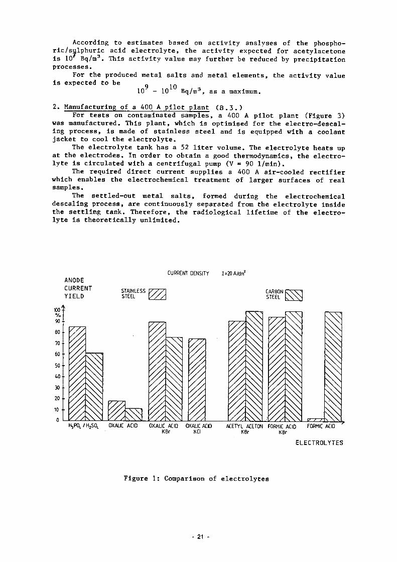
In addition to the already developed electrolytes (formic acid, oxalic acid), a third electrolyte was developed on the basis of acetylacetone 5% with potassium bromide (KBr). The electrolyte has a better anode-current-yield (ACY) than oxalic acid. The generated acetylacetona-tes are less soluble than the oxalates. The sediment is more coarse-crystalline. A comparison of the results is shown in Figure 1. The test results with acetylacetone are shown in Figure 2. The acetylacetone is consumed and metal salts are produced in the course of the electrochemical descaling process (ECD). It is necessary to regularly make up for the required acid percentage. The "admixed" KBr is not used up, and its concentration in the electrolyte solution remains unchanged. The electrolyte was tested on carbon steel samples and stainless steel samples.
The surfaces on the stainless steel samples were very rough after the ECD process (R > 30um; R > 10 um). This fact pointed to a selective dissolution of single alloying stainless steel components. However, an analysis of the electrolyte showed metal contents corresponding exactly to the composition of the stainless steel. This proves that the dissolution has not been selective.
As a result of the solubility coefficient of the produced metal salts, the concentration Increases up to a maximum value of 5 g/1. The above specified concentrations signify the saturation limits for the metal salt/electrolyte solution. After having reached this saturation limit (which, in the case of the phosphoric/sulphuric acid electrolyte used so far, is of about 130 g/1), the metal salts settle out in the following form: Fe(acac)„, Fe(acac)„, Co(acac)_, Ni(acac)„.
The metal salts in the electrolyte settle out in bivalent (70%) and trivalent (30%) form. In the case of stainless steel, all alloying constituents are in the electrolyte solution; cobalt and nickel are specified above as examples.
As a result of the settling out of the metal salts after having reached the solubility limits, it is ensured that radiologically balanced conditions are met. Radioactive metal ions are enriched in the electrolyte until the solubility limit is reached. If further radioactive metal ions are produced during the decontamination, they settle out and the resulting sediment can be removed. The maximum activity of the electrolyte solution is thus determined by the solubility of the salt and metal elements. In the case of acetylacetone, the service life seems to be almost unlimited as regards radiological aspects. If, as a result of fouling (oil etc.), the disposal of the electrolyte as waste is required after a certain time, it is recommended to electrolytically use up the residual acid, using inactive iron for the electrochemical dissolution. The spent electrolyte to be disposed of is composed of 1 wt% acetylacetone and 5 g/1 acetyl acetonates.
- 20 -
According to estimates based on activity analyses of the phosphoric/sulphuric acid electrolyte, the activity expected for acetylacetone is 10 Bq/m3. This activity value may further be reduced by precipitation processes.
For the produced metal salts and metal elements, the activity value is expected to be
10 - 10 Bq/m3, as a maximum.
2. Manufacturing of a 400 A pilot plant (B.3.) For tests on contaminated samples, a 400 A pilot plant (Figure 3)
was manufactured. This plant, which is optimised for the electro-descaling process, is made of stainless steel and is equipped with a coolant jacket to cool the electrolyte.
The electrolyte tank has a 52 liter volume. The electrolyte heats up at the electrodes. In order to obtain a good thermodynamics, the electrolyte is circulated with a centrifugal pump (V = 90 1/min).
The required direct current supplies a 400 A air-cooled rectifier which enables the electrochemical treatment of larger surfaces of real samples.
The settled-out metal salts, formed during the electrochemical descaling process, are continuously separated from the electrolyte inside the settling tank. Therefore, the radiological lifetime of the electrolyte is theoretically unlimited.
CURRENT DENSITY 1=20 A/dm2
ANODE CURRENT YIELD
HjP0 , , /H 2 S0 t OXALIC ACID OXALIC AC 10 K Br
OXALIC ACID KCl
ACETYL ACETON FORMIC ACID KBr KBr
FORMIC ACID
ELECTROLYTES
Figure 1 : Comparison of e lec t ro ly tes
- 21

Stainless steel samples
Anode current yield
17.1 100-1-
5 0 - -
Current d e n s i t T = 16 A/dmí I
C D I = 20 A/dm
Electrolyses Duration = 0.5 h Temperature = 323 K
A
35
EKES A I A IS •— pH = 5—' L-pH = 7—J ^— pH = 9—J
Figure 2: Test results with 5% acetylacetone solution with KBr (0.5 M)
— EIEKTR0LYTE
SEDIMENT CIRCULATION PUMP
Figure 3: The pilot plant 400 A
- 22 -

2.5. Optimization of Filtering Systems for Various Concrete Decontamination Techniques
Contractor: Salzgitter AG, Salzgitter, Germany Contract N": FI1D-0005 Working Period: January 1985 - June 1987 Project Leader: W. Ebeling
A. Objectives and Scope The effectiveness of mechanical and thermal methods for the deconta
mination of concrete surfaces has already been demonstrated. However, the collection and conditioning of the important amount of generated dust, aerosols and toxic gases needs further development.
As concerns the filtration during thermal decontamination, multistage storing filters, as currently used in the nuclear industry, have shown adequate efficiency, but their limited storage capacity precludes an economic operation. Concerning the effectiveness of filtration systems for mechanical decontamination, no extensive investigations have been undertaken, so far.
The aim of this research programme is to investigate various filter systems, such as storing filters, regenerative mechanical filters, electrostatic' filters, concerning their separation efficiency, their storage capacity and service life, including an analysis of the amount and size distribution of dust available at each filtering stage. The experiments will use dust generated by the above decontamination methods on non-radioactive concrete samples.
Based on existing data on radioactive concrete surfaces, a theoretical assessment on possible radioactivity inventories in the investigated filter systems will be made, with a view to their optimization for real applications.
B. Work Programme B.1. Modification and adaptation of the existing test facility for air
filtering systems. B.2. Acquisition of components for testing and concrete samples. B.3. Selection and mounting of various air filter systems. B.4. Implementation of various thermal and mechanical concrete decon
tamination procedures (flame spalling, grinding, chipping hammer, scarifier).
B.5. Measurement of airborn dust and aerosols by various methods. B.6. Analysis of the measurement records and evaluation of the tested
filters with respect to separation efficiency, retention capacity, radioactivity and costs.
23

C. Progress of Work and Obtained Results Summary During the period under report, the separation of dust arising from stripping operations was tested with two further types of regenerative filters. These filtering plants require a HEPA filter to be arranged downstream as a safety filter. The results obtained with the last tested filtering plant could not be utilized due to a measuring error of the instrument used. These tests have therefore to be repeated. In the first filtering plant, the arising dusts could be filtered out at degrees of separation in the order of 99%. The separating performance with this type of filter grows as the amount of retained dust increases. The best results could be achieved after the filter had once been charged fully and had then been cleaned. Afterwards the degrees of separation were in the order of 99.99%. According to expectations, the particle size analyses of the clean gas showed a shifting towards smaller particle diameters. The filtering plant presented in the 1st annual report was used in decontamination service. The suitability of this filter having an average degree of separation of 99.5% has been proved (B.4., B.5. and B.6.). 1. Objectives The purpose of further tests was to evaluate the usefulness of other filtering separators for use in concrete decontamination. The previous tests have shown that the largest amounts of dust are released with flame-scarfing and finish-cleaning with a wire brush. Only flame-scarfing burners and wire brushes were then used in the tests, which was also due to the fact that the particle size analysis of the raw gas yielded somewhat less favourable values than with the usual methods of removal, e.g. by chisel hammer, spike hammer, grinder. The filter described in the 1st annual report was additionally tested in trial decontamination service. 2. Filtering tests (B.5.) During the tests, the dust concentration and particle size distributions were determined both in the raw gas and downstream of the filter. The pressure rise in the filter was additionally recorded. 2.1 Filtering plants 2 A total of 6 cartridge filter elements each having a filter area of 10 m were used in the initially tested filtering plant. Ine pressure drop of the unloaded filter was approx. 200 Pa (V = 5,500 m /h). The dust-laden raw gas enters the raw gas chamber in a tangential flow. Baffle plates are installed to prevent a direct impingement on the filter cartridges. The dust is deposited on the outside surface of the star-shaped folded filter medium. The purified air passes inside the filter cartridges via diffusers to a fan and then leaves the unit. During operation- of the plant, the filter cartridges are cleaned automatically by pulsing air. The separated dust drops into a collecting funnel and is either discharged continuously via a rotary valve or sent to a collecting tank. The cleaning pulses are controlled by a control unit with adjustable pulse and break times. The second filtering plant contains two bag filter cassettes, each with a filter area of 11 m2. The pressure drop of the unloaded filter is in the order of 400 Pa (V = 2,000 nT/h).
24

After passing through a preliminary separator, the raw gas enters the bag filter cassettes, flowing from the outside to the inside of the bags which are individually stabilized by spiral springs. This causes the dust to be deposited on the outside. The cleaning of the filter cassettes takes place automatically and separately for each cassette by means of pulsing air. The bags are momentarily inflated due to the surge pressure, which causes the dust to be released. The' automatic cleaning system is adjusted to suit the existing conditions. During the cleaning phase, the raw gas continues to be admitted to the cassettes, so that the suction process need not be interrupted.
2.2 Results of measurements (B.6.) When the results obtained from the second filtering plant (bag filter) were evaluated, it became apparent that the measuring instrument, an Aerodynamic Particle Sizer APS 33, was not functioning properly. It is therefore necessary to repeat the tests, and the results can only be presented in the next report. Satisfactory results could be achieved with the first filter plant (cartridge filter elements) which was tested in the period under report.
2.2.1 Degree of separation Filtering separators show the poorest separating performance when in new condition. As the filter cake is built up, the degree of separation increases. For this reason it is recommended to load the filter elements once before start-up and to clean them subsequently. The particles remaining in the filter will then improve the degree of separation considerably. Following an advice given by the filter manufacturer, after a certain time had been spend on the trials, the filter was fully charged with a large amount of lime and cleaned subsequently. The two types of separation efficiency can be seen from Tables 1 and 2.
2.2.2 Particle size analysis The particle size analyses upstream and downstream of the filter are shown in Fig. 1 and 2. The particle size distributions in the clean gas show a shifting towards the smaller particle diameters. As was to be expected, this shift was not as marked as in the filtering plant described in the 1st annual report, which incorporated a downstream HEPA filter classification "S" inside the casing. In order to meet the requirements for technical safety, and to improve further the degree of separation, a HEPA filter classification "S" has to be installed downstream of the compact dedusting filter.
2.2.3 Filter cleaning The filter could not be charged fully during the tests. The rise in the pressure drop across the filter occurred very slowly. According to information provided by the manufacturer, a continuous service life of approx. 10 days can be expected at a raw gas dust concentration of approx. 100 mg/m . Only then the cleaning process has to be initiated at a pressure drop across the filter of A P = 800 Pa.
25 -

In the course of the tests, the filter cartridges were loaded with large amounts of lime until a limit value of 800 Pa was achieved. The filter was then cleaned with 5 compressed air pulses at 6 Bars. The pressure drop across the cleaned filter was equal to A P = 220 Pa (V = 5,500 m /h). After this had been done, an improved separating performance could be observed. 3. Decontamination tests (B.4. and B.6.) The filtering plant described in the 1st annual report was used for trial decontamination service in which the suitability of this filter could be proved. As part of this series of tests, contaminated plates were ground by means of grinding wheels. The contamination of these plates was formed by the radionuclide Co-60 accounting for approx. 80% and the nuclide Cs-137 accounting for approx. 20%. When these contaminated plates were ground, efforts were made to produce a maximum of dust. Insofar the test set-up differed from realistic conditions. Samples of dust were collected in the supply and discharge line of the filter, and these were then subjected to radiological evaluation. In the case of a direct dust suction, the contamination in the raw gas was approx. 1,443 Bq/m , and in the clean gas approx. 7 Bq/m . This corresponds to an average degree of separation of 99.52%. Since these tests were conducted in the last weeks of the year 1986, the total quantity of dust retained in the filter and the quantity of radioactivity retained in the filter cannot be stated as yet. This information will be given in the next period under report.
26 -

Table I Dust loads in the raw gas and in the clean gas, degrees of separation
1-
Stripping Method
Flame-Scarfing Wire Brush
Dust Loading Raw Gas C0
mg/m 77.2 766.8
Dust Loading Clean Gas- C,
3 mg/m 0.5 8.4
Degree of Separation
%
99.3 98.9
Table II Improved degrees of separation after initial filter charging/cleaning cycle "
Stripping Method
Flame-Scarfing Wire Brush
Dust Loading Raw Gas Cn
3 mg/m 72.2 766.8
Dust Loading Clean Gas C,
3 mg/m 1.5 . 10"2 3.3 . 10"2
Degree of Separation
%
99.98 99.996
200
100-S 3 Z
kil id
i
llllii
- 4 .
i 1 3 z
Ilium ilLu 0.6 1.0 2.0 4.0 6.0 10 15
Aerodynamic Diameter (urn) 0.6 1.0 2.0 4.0 6.0 10 15
Aerodynamic Diameter (um)
a) Raw Gas b) Clean Gas Fig. 1 Number concentration vs. particle size when flame-scarfing
20O0
1000
20
10
o - al U l l a -0.6 1.0 2.0 4.0 6.0 10.
Aerodynamic Diameter (urn) 0.6 1.0 2.0 4.0 6.0 10. 15
Aerodynamic 01 ameter (um)
a) Raw Gas b) Clean Gas Fig. 2 Number concentration vs. particle size when using the wire brush
27

2.6. Economic Comparison cf Decontamination and Direct Melting with a View to Recycling Scrap
Contractor: Gesellschaft für Nuklear-Service mbH, Essen, Germanv Contract N° : FI1D-0029 Working Period: Januarv 1985 - June 1986 Project Leader: K. G. Janherg
A. Objectives and Scope The decommissioning of nuclear facilities either reauires the final
disposal of large quantities of contaminated scrap metal or the decontamination to a degree which allows its further use in nuclear or other areas.
Decontamination technology is well developed and in most cases based on the application of highly corrosive agents or electrochemical processes. Recently, direct melting has been added to these procedures as it allows for the separation of Cs and Sr from the base material. However, the volatile contamination agents have to be retained by appropriate filter systems.
The objective of this work is to carry out an economic study of decontamination, direct melting and super-compaction, with a view to recycling of scrap, in order to establish a state-of-the-art cost structure for the decommissioning cf nuclear installations. This economic comparison is based on actual clean-up or decommissioning work executed by the contractor under industrial conditions.
This study takes into account the nuclear installations in Germany.
B. Work Programme B.1. Review studies B.l.l. Inventory of contaminated metal scrap until 1994. B.1.2. Review of existing decontamination methods. B.1.3. Review of licensing conditions for recycling of decontaminated
metal scrap. B.2. Assessment of the investment and running cost of the three follow
ing procedures: - decontamination of scrap metal followed by melting and release, - direct melting of scrap metal, followed by release, - super-compaction followed by disposal as radioactive waste.
28

C. Progress of work and obtained results Summary
During this period, the study was completed by the conclusions and the final report prepared.
Progress and results The analysis of the amount of scrap metal arising until 1994 from
normal operation, backfitting and decommissioning show figures between 4000 - 8000 tons per year.
The economic evaluation of the scrap metal conditioning procedures showed clear advantages for super-compaction of mixed small metal pieces, in particular if the geometries are complicated. The cost ranges between 2.5 and 5.5 DM/kg.
While at the beginning of the study in 1985 the decontamination costs for scrap metal of simple geometry were still rather high, starting at about 4.5 DM/kg, the improvement of the technology made a cost range possible starting at 2.5 to 3 DM/kg at the lower bound and about 9 DM/kg at the upper bound. In that range, decontamination and direct melting show comparable costs.
These relationships were found to apply in Germany in 1986 for the current release limits for cleaned scrap metal. The present licensing conditions allow direct melting only at average activities below 74 Bq/g.
Within the time-frame covered by the study, a total of about 200 tons of scrap had been melted directly and recycled. The results show a perfect homogenisation of the non-volatile activity like Co-60 within the metal mass, while other elements like: Cs are transferred to the slag and/or filter system. In this way, direct melting is also a decontamination process for some radionuclides, but to a great extent its efficiency resides in the homogenisation of the previously surface-bound activity within the total molten mass.
The self-shielding capability of the metal strongly reduces the theoretically still possible dose-rate of the product fabricated from recycled scrap.
A particularity of the German programme lies in the fact that the material resulting from direct melting is preferably recycled in the form of waste casks for nuclear reactors, thus further minimising the release of radioactivity to the environment.
The analysis of the costs for decontamination and direct melting shows no definite advantage for either side under the existing release/-recycling regulation in Germany. One could even say that decontamination is slightly less costly in most cases.
However, with the impending reduction of release limits, direct melting with recycling in form of waste casks etc. vili gain in competitiveness as the process costs remain constant, while those for chemical or mechanical decontamination will increase.
A further interest of the direct melting lieg in the reduction of the waste volume to be disposed of.
29
2.7. Remote Electrochemical Decontamination for Pot Cell Applications
Contractor: United Kingdom Atomic Energy Authority, Harwell Laboratory, United Kingdom
Contract N°r FI1D-0033 Working Period: April 1986 - December 1988 Proiect Leader: A. D. Turner
A. Objectives and Scope The primary aim of the programme is to develop and evaluate remote
liquid-based decontamination systems for metal surfaces. The bulk of the waste volume should be reduced to a reuse or low-level waste disposal category, while concentrating most of the activity in a small volume suitable for immobilisation. The goal of the development programme is to test these techniques in both alpha-active and alpha-beta-gamma hot cells in order to ascertain their usefulness as a component of an overall decommissioning strategy. As a result of the radiological environment, particular emphasis will be placed on remote operation in order to reduce occupational radiation exposure.
Two types of technique? based on the electrochemical dissolution of thin surface layers of the substrate will be investigated: immersion of small items in tanks for electroetching, and in-situ electropolishing. In both cases, reagents will be chosen with their subsequent disposal in mind.
P. Work Programme B.1. Investigation of immersion electroetching.
Optimisation tests on the synthetic and genuine waste samples. Design and construction of a full size unit with ancillary electrolyte management system. Testing of this unit inactively, and in hot cell facility. Investigation of in-sitr electropolishing.
B.2.1. Optimisation tests on inactive, synthetic and genuine waste samples.
B.2.2. Design and construction of an automatically controlled unit for use with a remote handling system.
B.2.3. Testing of the unit inactively and in the high alpha-beta-gamma active handling facility.
B. B.
B. B.
, 1 . , 1 .
, 1 . . 2 .
,1 .2
.2
30 -
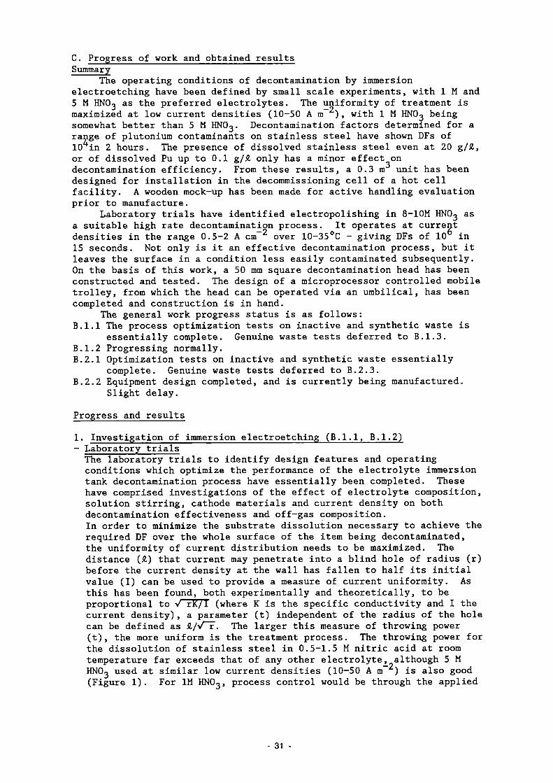
C. Progress of work and obtained results Summary
The operating conditions of decontamination by immersion electroetching have been defined by small scale experiments, with 1 M and 5 M HNOo as the preferred electrolytes. The uniformity of treatment is maximized at low current densities (10-50 A m - ) , with 1 M HNOg being somewhat better than 5 M HNOo. Decontamination factors determined for a range of plutonium contaminants on stainless steel have shown DFs of 10 in 2 hours. The presence of dissolved stainless steel even at 20 g/A, or of dissolved Pu up to 0.1 g/A only has a minor effect on decontamination efficiency. From these results, a 0.3 m unit has been designed for installation in the decommissioning cell of a hot cell facility. A wooden mock-up has been made for active handling evaluation prior to manufacture.
Laboratory trials have identified electropolishing in 8-10M HNO3 as a suitable high rate decontamination process. It operates at current densities in the range 0.5-2 A cm over 10-35°C - giving DFs of 10 in 15 seconds. Not only is it an effective decontamination process, but it leaves the surface in a condition less easily contaminated subsequently. On the basis of this work, a 50 mm square decontamination head has been constructed and tested. The design of a microprocessor controlled mobile trolley, from which the head can be operated via an umbilical, has been completed and construction is in hand.
The general work progress status is as follows: B.l.l The process optimization tests on inactive and synthetic waste is
essentially complete. Genuine waste tests deferred to B.1.3. B.1.2 Progressing normally. B.2.1 Optimization tests on inactive and synthetic waste essentially
complete. Genuine waste tests deferred to B.2.3. B.2.2 Equipment design completed, and is currently being manufactured.
Slight delay.
Progress and results
1. Investigation of immersion electroetching (B.l.l, B.1.2) - Laboratory trials The laboratory trials to identify design features and operating conditions which optimize the performance of the electrolyte immersion tank decontamination process have essentially been completed. These have comprised investigations of the effect of electrolyte composition, solution stirring, cathode materials and current density on both decontamination effectiveness and off-gas composition. In order to minimize the substrate dissolution necessary to achieve the required DF over the whole surface of the item being decontaminated, the uniformity of current distribution needs to be maximized. The distance (A) that current may penetrate into a blind hole of radius (r) before the current density at the wall has fallen to half its initial value (I) can be used to provide a measure of current uniformity. As this has been found, both experimentally and theoretically, to be proportional to V rK/I (where K is the specific conductivity and I the current density), a parameter (t) independent of the radius of the hole can be defined as A/vT. The larger this measure of throwing power (t), the more uniform is the treatment process. The throwing power for the dissolution of stainless steel in 0.5-1.5 M nitric acid at room temperature far exceeds that of any other electrolyte, although 5 M HNOo used at similar low current densities (10-50 A m ) is also good (Figure 1). For IM HNOo, process control would be through the applied
31

pectrometry for H~, no significant off-gas production was 1.8 cm h A for stainless steel and 9 cm h A
voltage, while for 5M HNOo it would be by a constant cell current. Investigations of the effect of dissolved steel on bath performance have shown that metal concentrations up to 20-30 g/£ can be tolerated by continuous dosing with concentrated HNOo to maintain a constant free acidity. While fluoride or oxalate additions, or an increase in current density for nitric acid concentrations above 3 M can significantly accelerate the treatment rate, the throwing power is consequently decreased. As a typical treatment time in dilute nitric acid is only 2 hours for decontamination factors of ^ 10 , the maximizing of throwing power is seen to be of greater importance -especially for the treatment of complex shapes. Titanium baskets have proved adequate as anode current feeders to articles placed in them for decontamination. A high degree of uniformity of treatment can be obtained for a single layer of artefacts. A range of relatively inexpensive cathode materials available in sheet form have also been investigated for stability and the composition of any off gases. From an evaluation of weight losses in dilute nitric acid at various current densities, titanium proved to be the best (with essentially no discernible corrosion) followed by 310 stainless steel. From the analysis of gaseous products by chemiluminescence for NO and N0~ and mas detected (only for Ti: in the latter case even this could be suppressed to 2 cm h A by the presence of 3 mM Pb(NOo)o)- As a direct consequence of negligible hydrogen production, there is no flammability risk. Also, the very small overall gas volumes produced, as indicated by the absence of any visible bubbles, will avoid the formation of any aerosol - thus making local off-gas treatment unnecessary. The effects of stirring the electrolyte have also been investigated. While the throwing power is enhanced slightly, the off-gas is increased marginally and the treatment rate declines. Thus, it has been decided on balance to operate the full-scale plant with a static electrolyte -thus further simplifying its design. Decontamination factors (derived from surface a counting) have been determined in a glove box as a function of applied potential for the treatment of plutonium contaminated stainless steel coupons under a variety of conditions - including type of contaminant, dissolved stainless steel and plutonium concentrations in the electrolyte. While most of the work has been carried out with flat plate coupons, confirmatory trials have also been conducted on tubular sections to represent a more complex geometry. While both 1 M and 5 M HNOo are equally effective for the removal of P U ( N 0 Q ) ¿ and colloid contaminants, the stronger acid is better for PuOo contamination. As long as the free acid concentration is maintained, dissolved substrate levels up to 20 g/A have only a minor effect on decontamination performance - with DFs of <\. 10 typically achieved in 2 hours. While re-adsorption of activity is possible in potential regions where an oxide film is able to reform, even this is low at 0.1 g/£ Pu (20 Bq/cm ) and substantially below this at the potentials applied during decontamination (< 5 Bq/cm ). Decontamination unit construction
o As the result of this laboratory work, a 0.3 m decontamination tank unit for demonstration in the Decommissioning Area of one of the Harwell Active Handling facilities has been designed. It will be situated below the false floor of the cell, and may be covered over by a lid during operation to permit this area to continue to be used during the 2 hour treatment time. The tank will be fitted with
32 -

titanium cathodes, and a titanium basket current feeder will be used for the treatment of smaller objects. Rinsing and drying units will also be installed. Many of the long order items have already been received, and the remainder of the plant is about to go out to manufacture. A wooden mock-up has been made to assist in the development of active handling.
2. In-situ electropolishing - Laboratory trials From laboratory trials, electropolishing in a 8-10 M HNO, electrolyte has been selected as a high rate decontamination process suitable for in-situ applications. It operates at acceptable currents (0.5-2 A cm ) over a 10-35°C temperature range giving treatment times of -\< 15 seconds. Electropolishing is not only effective in minimizing the extent of metal dissolution required to achieve the desired DF, but it also leaves the surface in a microsmooth condition (Figure 2) that picks up less activity subsequently and is in any case easier to clean. In shielded fume hood experiments, DFs of 10 have been demonstrated -essentially reducing dissolved fuel contamination to background levels (Figure 3). A range of engineered devices have been designed to attach to the surfaces being treated. The first to be tested comprises a 50 x 50 mm square treatment area, which will encompass most hot-spots. However, larger areas may be decontaminated by sequential treatment of adjacent squares. The device is held onto the surface by a vacuum applied between concentric soft seals. Titanium has again been selected for the cathode, as under the high HNO3 concentration, high current density conditions used, not only does it not suffer any weight loss but insoluble gas production (Hg, NO) is suppressed, thus permitting slow electrolyte flow rates to be used (-\> 3 cm /s). This makes a 'once through' use of electrolyte practical, thus enabling the electrolyte stock tank and delivery pump to be positioned outside the containment as they remain uncontaminated.
- Decontamination unit construction The design of a mobile unit for use in active areas has recently been completed, incorporating electrolyte supplies, pumps, power supply and a microprocessor controller. A variety of decontamination heads can be connected to the trolley through an umbilical. The use of a microprocessor enables the unit to be automatically and safely operated due to extensive monitoring of process parameters - thus minimizing the need for operator intervention. The construction of this unit is now in hand.
List of Publications /l/ TURNER, A.D., JUNKISON, A.R., POTTINGER, J.S. and DAWSON, R.K.
Spectrum 86, ANS meeting on Waste Management and Decontamination and Decommissioning, September 1986. "Electrochemical decontamination of metallic radioactive waste".
33

electrolyte
0.5M Oxalic acid
Phosphor \c acid based electropolishing electrolyte
IM HNO3 + O. l.M MaF
IM HNO,
current dens it y (A m - 2!
25
200
l.rowincT Po-*
200
600
200
200
50
10
25
1
Fig. 1 A comparison of throwing power (uniformity of substrate dissolution) for various electrolytes.
20 um
As received 2B 321 stainless steel
2B stainless steel after 15 s electropolishing
in nitric acid
Fig 2 Substrate smoothing by electropolishing.
34

1° .-
10 -
10
10
10
o ü d) c 2
10
10
B a c k g r o u n d
25 i iGy/h a t
50 ram
I' ■ 'I 2B r o l l e d 316L
□ E l e c t r o p o l i s h e d 316L
W a t e r s w a b 8M HNO, swab
E l e c t r o -p o l i s h i n g
i n HNO,
Fig 3 Relative Decontamination Factors for the removal of dried fuel solution on 316 stainless steel.
35

2.8. Decontamination with Pasty Pickling Agents Forming a Strippable Foil
Contractor: Max Morant Chemische Fabrik, Aschau, Germany Contract N°: FI1D-0034 Working Period: July 1986 - June 1988 Project Leader: H. Weichselgartner
A. Objectives and Scope The main objective of this research is the development of a deconta
mination procedure by applying onto the contaminated surface (in a one-step or multi-step process) pasty, chemically aggressive agents causing dilution and absorption of the contaminant and then hardening to forma strippable foil. The use of such a foil will result in following advantages, with respect to usual techniques:
sensibly shorter operating duration resulting in lower personnel doses;
- reduction of the arising secondary waste volume because there is no need for washing; the volume of the spent strippable foil is much smaller than currently used water volumes; optimal conditioning of the radioactive waste due to its fixation in a solid (foil);
- an accidental contamination in a controlled area can easily be fixed and covered avoiding its propagation.
B. Work Programme B.1. Development and optimisation of a high-quality strippable foil,
ready for industrial application, taking into consideration various physical and chemical properties, such as ability to decontamination, strong adhesion, appropriate viscosity, leak tightness, tensile strength.
B.2. Development of the most appropriate operation procedures, including different deposition methods and an optimisation of the layer thickness.
B.3. Commissioning testing under realistic conditions, including various types of surfaces and tests with radioactive conditions in hot cells.
B.4. Development of a technology for industrial application, including the preparation of a users' manual, taking account of gained practical experience.
36

C. Progress of Work and Obtained Results Summary
Polyvinyl alcohols and polyvinyl acetates were found as matrix materials for the strippable foils. In a series of tests, several solvents, emulsifiers and softeners and also inorganic and organic acids were investigated concerning the compatibility of the foil's matrix material with these reagents. A basic composition was found, which served as standard mixture for further tests during which the chemical and physical properties of the foil vrere investigated.
In order to simplify these tests, all components of the foil, including hardening resins, were mixed together and the mixture was applied in a single-step procedure by brushing it upon various substrates. After a hardening time, from 4 to 12 h, the foil was pealed off the substrates and both foil and substrate were examined thoroughly.
Also, decontamination tests were performed with this standard mixture in a single-step mode. Decontamination factors were found to be acceptable for tritiated substrates and in some cases, e.g. with copper or stainless steel substrates, also with Cs and Co contamination.
During decontamination tests at the "Institut für Transurane", it appeared that the material cannot be applied by "airless spraying", a method preferred in nuclear industry. This constitutes a serious drawback mainly concerning the matrix material of the foil.
Progress and Results 1. Investigations on the production of a prototype foil (B.l.)
From a large number of test mixtures with different types of poly-viol and various concentrations of additives, a "standard pickling and decontaminating mixture" with the test N° 1309 was chosen, which proved to be optimum with respect to foil formation, elasticity, tearing strength, adhesion to background and drying time.
The chemicals included in this mixture have, in general, proved to be suitable for degreasing and pickling metals. In addition, their pickling effect was continuously monitored during development of the standard mixture.
Main components of mixture metals N° 1309 are: - 36 g Wacker Polyviol M13/1A0 - 180 ml ethanol, 96% and 120 ml H O - 30 ml PEG 200 (Polyethylene glvcol) - 18 ml ethylene glycol - 10 ml o - H PO,, 85%
5 ml lactic acid, 80% - 15 ml citric acid, 20%
15 ml "resin mixture" (Plastopal dissolved in acetone).
2. Test results with the prototype foil (B.l.) All tests in the first report period were conducted with the single-
stage prototype foil N° 1309 or with one with a slight modification. There are several reasons for dispensing with multi-stage application for the time being: - All tests for determining a suitable foil base material also arrive at
their objective in one stage. - Additives, such as softeners, dissolving intermediaries, wetting
agents, thickeners and dyes, can be determined more quickly in the single-stage procedure.
- Conducting cold tests (pickling effect on metals, degreasing, adhesion to other backgrounds, e.g. glass, PVC, acryl, concrete) is quicker and
- 37 -

simpler both in the laboratory and, even more so, by third parties. - Hot tests, which were mainly conducted by third parties (Institut für Radiochemie at TU München and Institut für Transurane at Leopoldshafen) and which were merely intended to demonstrate the basic suitability for decontamination purposes, can likewise be conducted more simply and quickly in one stage.
The standard mixture N° 1309 was applied to simple sheets made of carbon steel, stainless steel, brass, copper and aluminium by pouring, brushing and spraying, and the curing time, adhesion, strippability, thickness of foil, tearing strength, elasticity of the foil as well as the pickling effect on and the degreasing of the metal substrates were subjectively determined.
3. Decontamination of tritiated substrates (B.3.) These tests were conducted in a tritium laboratory at the Max-
Planck-Institut für Plasmaphysik in Garching. For this purpose, small dishes made of teflon, aluminium, copper
were contaminated with tritium in the following manner: one capsule of a 3H standard (Baker-Instand 3H-W, Art. N° 4593 with an activity of 99,300/dpm - Aug 85) was dissolved in 9 ml of water, and then 1 ml was put into each dish. After drying, the activities were measured with a wiping test assembly, application "K" of FAG Kugelfischer. The following values (averaged from several measurements) were obtained for: Cu: 1750 ipm, Al: 1800 ipm, Teflon: 1600 ipm.
The surface thus contaminated was then painted with the prototype stock solution N° 1309 and left for a day till completely cured. Thereafter, the foil was stripped without leaving any residue and the dishes were again measured. There was no longer any activity on any of the three dishes.
In general, it should be noted that results of decontamination tests on tritiated surfaces can only be conditionally taken as a basis for further developments of the decontamination foil, since the tritium occurs on the surfaces mainly as THO (tritium water) and consequently is not really comparable with contamination encountered in nuclear plants (corrosion, deposits, greasy dirt, pain residues, salts and the like simultaneously).
4. Decontamination of Co-60 and Cs-137 In collaboration with Institut für Radiochemie at TU München, some
tests were also conducted on samples of wood, glass, PVC and iron contaminated with Co-60 and Cs-137. The results are listed in Table I (see next page).
5. Decontamination tests at Institut für Transurane (B.2. and B.3.) In 1986, a few tests were conducted to check the decontamination
effect of the strippable decontamination foil (type N° 1309) in hot cells and glove boxes, in the controlled area of Institut für Transurane.
In nuclear installations, application techniques such as brushing, painting, rolling or priming, are ruled out if the glove boxes, hot cells, and even more complex facilities have to be decontaminated. Such methods can only be considered for decontamination of small components. Preference is apparently given to the special technique of airless spraying at pressures of up to 200 bar.
The foil material Nc 1309 was not suitable for this purpose; the spraying nozzle only ejects a fabric of fine threads which do not combine to form a closed layer on the substrates. Partly in collaboration with Bosch Spritztechnik, Weilheim-Teck, various nozzles were tried, the
- 38

spraying pressure and the viscosity were varied, and finally, rotating nozzle heads were used. These cause twisting of the sprayed threads, which has proved to be useful in adhesives technology. None of these tests yielded useful results and so it had to be concluded that the basic composition of prototype foil N° 1309 probably has to be modified, primarily with respect to the film former.
After dilution with warm water, the strippable foils can readily be sprayed with compressed air at 3 to 5 bar. The sprayed-on foil formed a uniform, closed, transparent film which can readily be completely stripped from steel, Al, PVC and plexiglass surfaces.
It is possible to apply the foil with a spray gas to produce protective coatings which can be used outside "hot" zones.
! Item ! N° ! 015 ! 016 ! 017 ! 018 ! 019 ! 020 ! 021 ! 022 ! 023 ! 024 ! 025 ! 026
Table I
Pickling foil type 1309 1309 1309 1309 1309/m 1309/m 1309/m 1309/m 1309/m 1309/m 1309/m 1309/m
Decontamination of
Nuclide
Co-60 Co-60 Co-60 Co-60 Cs-137 Cs-137 Cs-137 Cs-137 Cs-137 Cs-137 Cs-137 Cs-137
Material
wood glass iron PVC wood wood glass glass iron iron PVC PVC
Co-60 and Cs-137
Activity Al
199 x 103 21600 57 x IO3 7480 190 x IO3 130 x IO3 28 x IO3 8800 38 x IO3 3 x IO3 11 x IO3 1000
Activity A2
164 x IO3 13000 2500 1520 130 x IO3 110 x IO3 8800 8400 3 x IO3 2400 1000 885
DF !
1.2 ! 1.7 ! 23 ! 5 ! 1.4 ! 1.2 ! 3.2 ! 1.2 ! 12.4 ! 1.26! 11 ! 1.2 !
1309/m = slightly modified recipe Al = Activity before decontamination (ipm) A2 = Activity after decontamination (ipm) Background activity: Ao = 145 ipm.
6. Conclusion A prototype pickling foil was produced and investigated, which did
not meet all the requirements of the multi-stage development objective. However, it was also possible with this single-stage prototype foil, to test and in part optimise important properties, such as formation, adhesion, elasticity and strippability of the foil itself, pickling and degreasing effect on a series of metals (carbon steel, stainless steel, Al, Cu, brass) and non-metals (glass, PVC, plexi glass, etc.). In laboratory tests, the decontamination effect of this standard mixture (product N° 1309) was also investigated on samples contaminated with tritium (THO). In general, the decontamination factors were found to be good to satisfactory, particularly on metals. Tests were also conducted on Co-60 and Cs-137.
Beside these laboratory tests, practical application tests were also conducted with the single-stage strippable decontamination foil N° 1309 at the Wiederaufarbeitungsanlage Karlsruhe. Spraying the foil with compressed air is ruled out here as well. The foil was painted onto the surfaces to be decontaminated.
On smooth surfaces (steel, decontamination paint), the foil was found to be readily strippable and to achieve good decontamination factor of 10-100.
- 39

2.9. Rack-torch Unit for Remote Decontamination of Concrete
Contractor: Société des Techniques en Milieu Ionisant, Trappes, France
Contract N°: FI1D-0035 Working Period: November 1986 - August 1987 Proiect Leader: J.F. Rlanchin
A. Objectives and Scope The decontamination of concrete, in the framework of the decommis
sioning of nuclear installations, poses a particular problem, due to the migration of contaminants into cenerete to a depth of 1 to 5 cm.
The technique of fissuration by rack-torch and rapid cooling is expected to suit application in a hostile environment and to involve notably lower radiation exposure of the personnel than the methods used nowadays such as hammering.
The obiective of the present research is the setting and perfecting of the fissuration technique by rack-torch with a view to its secure and optimised use in decontaminating concrete structures.
B. Work Programme B.1. Design and manufacturing of the rack-torch prototype. B.2. Optimisation of the concrete fissuration technique including the
study of motion of the prototype (manual or automatic), the piezoelectric ignition device, the system for aspiration, sedimentation and filtration of aerosols and concrete particles, various types of rack-torch for the scraping of different surfaces.
B.3. Scraping tests on various types of concrete (inactive and contaminated samples).
B.4. Design and manufacturing of the industrial prototype. B.5. Application of the fissuration technique to a nuclear installation
including recommendations for the best use of this technique.
C. Progress of Work and Obtained Results Preliminary calculations of liquid nitrogen, oxygen and tetrem.-
(C-H.) consumption and quantities of effluents produced have been performed.
40

2.10 Feasibility of Concrete Decontamination Using a Plasma-augmented Burner
Contractor: Société Bertin et Cie, Plaisir, France Contract N": FIlD-0063 Working Period ; January 1987 - December 1987 Project Leader: M. Reybillet
A. Objectives and Scope The contamination of concrete in nuclear installations is mainly
located in the vicinity of the exposed surface, to a depth generally estimated at a few millimeters. Therefore, during the decommissioning of these installations, techniques are preferred which are capable of removing concrete by successive thin layers so as to minimise the quantity of radioactive waste generated. On the other hand, the minimisation of aerosols emission, dangerous to workers, constitutes a second criterion of choice for decommissioning techniques.
Contrary to traditional mechanical techniques, electrocombustion is likely to respond simultaneously to the two previous criteria, causing superficial melting and weakening of the concrete by very high temperatures.
The aim of the present research is to determine by inactive experiments on the existing test bench:
the efficiency of the plasma burner as regards the shallow destruction of concrete at a temperature which may exceed 3000°C; the approximate levels of aerosol emission and NO involved in this operation.
B. Work Programme B.1. Optimisation of the plasma-augmented burner under non-radioactive
conditions as a mears for removing concrete layers, including the following parameters: concrete structure, gas composition, temperature and velocity of exit gas.
B. 2. Application cf the plasma burner to two types of concrete, one of them impregnated with non-radioactive cesium chloride for simulation of the contamination.
B.3. Continuous measurements of aerosol and NO gas quantities produced and analysis of aerosol concentration and particle size.
B.4. Conclusive assessment of obtained results and elaboration of recommendations for the best application to concrete decontamination.
41

3. PROJECT N°3; DISMANTLING TECHNIQUES
A. Objective
The objective of this project is the development of the special techniques needed for dismantling the large steel components (e.g. reactor pressure vessel) and reinforced-concrete structures (e.g. reactor shielding) of redundant nuclear installations, account being taken of the particular requirements due to radioactivity.
B. Research performed under the 1979-83 programme
The following techniques have been tested and developed: - thermal techniques such as plasma-arc and oxygen cutting and cutting
by laser beam; - mechanical techniques such as sawing;
explosive techniques for the dismantling of concrete structures.
C. 1984-88 programme
The dismantling techniques needing further development should be chosen account being taken of the results of the first programme. Particular emphasis will be laid on the minimisation of secondary waste and contamination, and of occupational radiation exposure.
The necessary equipment for the remote operation of dismantling and other decommissioning techniques will be an important new aspect for investigation under the 1984-88 programme.
D. Programme implementation
Fourteen research contracts relating to Project N°3 were being executed in 1986, including seven new contracts concluded in 1986 as well as one contract whose execution has been completed in 1986. Besides, three contracts were still at the stage of negotiation at the end of the year.
42

3.1. Ventilation and Filtration Techniques for Thermal Cutting Operations
Contractor: United Kingdom Atomic Energy Authority, Windscale Nuclear Laboratories, United Kingdom
Contract N°: FI1D-0006 Working Period; October 1984 - March 1987 Project Leader: J.R. Wakefield
A. Objectives and Scope The dismantling of nuclear plant calls for the segregation of
different materials and combinations of materials. These are largely mild steels, carbon steels and stainless steels. A thermal segregation process has advantages in that it is less sensitive to material thickness and type and is more easily controlled by remote means. Its disadvantage is that it generates high concentrations of sub-micron aerosols which cause rapid plugging of absolute filters. To extend the life of these filters and to reduce the volume of secondary waste, some form of pre-filtration is necessary.
The object of this work programme is to: categorise aerosols produced by a range of thermal cutting processes; identify suitable pre-fil-tration devices; test them against cutting aerosol challenge; recommend a suitable filtration system which minimises secondary waste production and the man-Rem dose to operators. This work will initially be carried out in a purpose-made rig and will continue to a full-scale mock-up of the Windscale AGR plant (HERO facility).
Co-operation with CEA Saclay (contract N°FIlD-0007) will take place over the work period and will take the form of information exchange and the interchange of apparatus and personnel.
B. Work Programme B.1. Literature survey for identification of former work and of alter
native techniques. B.2. General investigation into aerosol behaviour for various cutting
techniques. B.3. Construction of a filtering rig and detailed study of various
filtration systems. B.A. Assessment of various tested filter systems for their appropriate
ness in decommissioning applications with active aerosols. B.5. Execution of full-size ventilatior trials including aerosol deposi
tion in ductings and plate out on the decommissioning machine.
- 43

C. Progress of Work and Obtained Results
Summary Work has continued in the two ventilation/filtration rigs, using the
oxy-propane-powder cutting torch, described in the 1985 Annual Report of the Commission III. In the building B2.1 cutting cell shown at Figure 1, ventilation flow 5000 n^hr-1, the electrostatic precipitator (ESP) efficiency, its relationship to the collector plate voltage, and a vibratory plate cleaning technique have been investigated. The HERO Development Facility ventilation system (15,000 n^hr-1 flow) was adapted to incorporate an ESP test loop to continue efficiency tests, the collector plate voltage/efficiency relationship, and also to test the effectiveness of the ESP in protecting a HEPA filter. The system was later modified to incorporate the pre-filter test loop from CEA Saclay, see Figure 2. Three pre-filters - an ESP, an electrocylone and a bag filter protecting a HEPA filter - were successively and successfully tested. During these tests when extensive mild steel and stainless steel cutting took place, measurements were taken of fume concentration in the HERO vault, see Figure 3, and particle deposit concentrations on passive surfaces in the vault and in the ventilation ducting were measured.
A cartridge filter with reverse pulse air jet cleaning was the subject of alternative pre-filter tests, set up in a transparent test housing, see Figure A, by colleagues from AERE Harwell and tested in the HERO ventilation system against the challenge of fume from cutting stainless steel plate. Regeneration of the filter by pneumatic ejection of particles from the filter medium thus reducing flow resistance was successful, and the filter maintained very high efficiency throughout.
Progress and Results
1. Literature survey (Bl) The recent development of circular HEPA filters /2/ produced in
radial flow cartridge form should provide better systems in terms of filter seal, reduced handling problems and ease of disposal of contaminated filters via existing disposal routes.
2. Investigation into aerosol behaviour (B2) The programme for the joint experiments in the HERO facility with
the French group from CEA Saclay was an extensive one. The cutting time for the nine experiments was 22 hours over the eight day period; 70 m of 80 mm mild steel (MS) plate were cut, and over 30 m of 25 mm stainless steel (SS) plate. Small plastic and metal foil surfaces were placed on or within 1 metre of the floor of the vault, and one pair on a platform 6 metres above the floor, ie about 2 to A metres above the torch traverse area. These plastic and foil surfaces were left undisturbed throughout the whole 8 day period. Excluding the surfaces at the high level, the deposits were in close agreement, the five plastic surfaces averaging 24 g /m2 +A.7, -1.5; the foil surfaces averaging 22.2 g /m2 +A.A, -3.7. One pair had been placed in the annular space outside the simulated vessel. The values, 23.9 and 22.6 g /m2 support the theory that particles are elevated towards the top of the vault by the thermal plume before mixing and being drawn down towards the base and the air extract grills.
Four small air sampling pumps drawing 2 litres/min were placed at different heights in the vault, see Figure 3, to measure fume concentration. The mean value for the lower samplers was 20.1 mg/m3, at
- 44

the mid vault position 18.7, and at the top 17.4, when cutting with powder. Cutting without powder the corresponding values are 0.5, 0.45 and 0.6 mg/m3. The samples above the air inlet grill at the top of the vault gave a mean value of 0.6 mg/m3 when cutting with powder and virtually zero when cutting without powder.
3. Study of pre-filtration systems (B3) The cutting cell in the building B2.1 has an ESP pre-filter, see
Figure 1. The ESP incorporates pneumatic powered vibrators on the collector and ionising cells, to remove particles which then fall into a hopper. Following operation of the vibrators there was some recovery of efficiency to 85% but a technique for control of the vibrators must be investigated. About 2 Kg of particles were removed during the vibration but the plates retained a coating of particles. There was also an excessive build up of particles on all the surfaces and ledges in the cabinet. Efficiency at this point was reduced to ~50% from initially over 90%. Vibratory cleaning will be necessary at frequent intervals to prevent such a large reduction in efficiency. A Phoenix total light scattering photometer was used to measure concentration and efficiency. The length of cut of the 80 mm MS plate was approximately 3.5m. A technique for removing the radioactive collector and ionising cells for washing is being developed. There are clear advantages in handling and disposing of the concentrated mass of particles from the hopper.
An alternative pre-filter system, a Donaldson-Torit filter cartridge with reverse pulse jet cleaning equipment, provided by Chemical Engineering Division, AERE Harwell, was set up as a loop to the main HEPA filters in the HERO facility. A cutting programme was arranged to cut
SS plate 25 mm thick. The pre-filter efficiency and changes in pressure drop (Ap) were recorded. A TSI 3030 particle analyser was used to monitor the experiment. The total cutting time was 10 hours, in which time the main HEPA Ap increased from 15 mm to 230 mm, were changed after 5 hours cutting, and over the second 5 hour period the HEPA Ap increased from 15 mm to 232 mm. The pre-filter had an efficiency >99.95%. The progress of the experiment is shown at Figure 6.
4. Assessment of filter systems for decommissioning applications (B4) The protection afforded to a HEPA filter by an ESP pre-filter was
investigated in an ESP/HEPA loop, a parallel circuit to the main HERO HEPA filters. Over a 110 minute run, whilst cutting SS the Ap across the main HEPA filters increased from 58 mm to 180 mm water, ie a 3.1 fold increase in Ap. The HEPA protected by the ESP increased its Ap from 33 mm to 61 mm water, ie a 1.85 fold increase in resistance. The protection factor of the ESP was 1.67. The relationship between ESP penetration and the collector plate voltage was established over a series of experiments, when cutting MS, MS with powder and SS with powder. This is shown in Figure 5. The voltage reduces as the plates become coated in particles with a corresponding increase in penetration (efficiency % is 100 minus penetration % ) . This is a safe way of remotely monitoring the ESP efficiency.
5. Full-size ventilation trials (B5) The HERO Development Facility has a full-size ventilation system
with a throughput of up to 15,000 m3/hr. The rig incorporates sampling points at which fume concentration and flow velocity can be determined. The extensive cutting programme prepared for the Saclay pre-filter tests ensured that large amounts of fume would be generated in the vault (see
- 45

Section 2). Measurements were made of particle deposition on the inside surface of the nozzles connecting the French test loop with the main duct at Figure 2. The nozzles were sized to suit the flow requirements of each pre-filter to take an isokinetic sample of fume. The total throughput for the last group of three experiments - for the bag filter -was 0.78 g for a 3 hour period cutting MS, 16.1 g for a 2 hour period cutting MS with powder, and 68.8 g for a 2 hour period cutting SS with powder. The deposition in the duct was 0.3 g /m2 of inside surface. This is 0.33% of total fume throughput per square metre. These data also highlight the advantage of not using powder injection to the flame when cutting mild steel. Particle deposition on duct surfaces will be the subject of further investigation.
Cooperation with CEA Saclay The collaboration between CEA Saclay and WNL was successfully
consummated with the incorporation of the French pre-filter test loop into the HERO Development Facility ventilation system, see Figure 2, and the subsequent testing of three alternative pre-filters in parallel with tests on the WNL ESP pre-filter. (A joint report will be issued).
Nozzles were inserted into the main duct to allow an isokinetic sample flow to be diverted to the French loop, to suit the flow requirements of each pre-filter. The loop was then connected to the main duct at the fan inlet. A late modification to the system allowed the re-connection of the WNL ESP loop for parallel tests of the ESP efficiency and plate voltage relationship, along with the French pre-filter tests. The HEPA filter resistance data is shown at Figure 7.
References (1) CEC - EUR 10740. The R & D Programme on Decommissioning Nuclear
Installations, First Annual Progress Report (1985), p32-39. (2) PRATT, TINKLIN. Symposium on Gaseous Effluent Treatment in Nuclear
Installations. Luxembourg, October 1985. Development of Circular Filters for Active Facilities.
46 -

HEPA FILTERS
CUTTING CELL BUILDING B2.1
FIGURE 1 FLAME CUTTING AND FUME CHARACTERISATION RIG
FRENCH LOOP
HERO VAULT WALL
FRENCH BAG FITER
FRENCH HEPA FLTER
FLEXBLE DUCT
FIGURE 2 FRENCH PRE-FILTER TEST LOOP INCORPORATED
INTO THE HERO VENTILATION SYSTEM
CENTRFUGAL FAN HOUSING
47

VENTLATION INPUT
oo
HOIST -lOODKg
PLATE SAMPLES H FRAME
THREE FLOW DAMPERS
VENTLATION EXTRACT TO FITER SYSTEM
PULSE-JET CLEAMNG SYSTEM
HAM CENTRFUGAL FAN
AR SAMPUNG PUMPS
GENERAL UGHTMG
MANIPULATOR ACCESS PLATFORM
TELESCOPIC HAST
LIGHT GAUGE CYLINDRICAL CONTAMMENT
PLATE-OUT COLLECTION DISHES
SMGLE HEPA FITER UMT
SUPPORT FRAMEWORK
DUCTNG
GLASS HOUSMG
«LET DUCT FROM HERO VAULT
FIGURE 3 HERO DEVELOPMENT FACILITY FIGURE 4 REVERSE-PULSE JET-CLEAN FILTER CARTRIDGE SYSTEM
TEST LOOP HERO VENTILATION SYSTEM

MS MILD STEEL MS+P MILD STEEL + POWDER SS+P STAINLESS STEEL + POWDER
MAIN HEPA FLOW (8 filters) M3/HR
12540 h 11770 i
FILTER 4 CHANGE
14470 11760 12250
FILTER CHANGE
200 400 600 0
FILTER OPERATING TIME MINUTES
F 1 6 . 7 HEPA FILTER PRESSURE DROP VS CUTTING TIME
i/> LU
CC CC LU LU O O
s:* O O
LD
< O >
a- o. * +
LO 1/1 t o z: z: ui
ATMOSPHERIC
CUTTING F
UME
CUTTING F
UME
CUTTING F
UME
> < O X
<
-20
Q. o o •
OSOLS
ce 1 LU fc> < r
X /
/
"•o
-10
I
5«î
CC X (— co LU Z z O LU iH C h
a <t Q _ l CO LU LU ce
L3 * +
< £ I LU Q. iy,
z < t c t ^û
3 o. o: ,„ ^ o < LU o "̂ ^ in ^ ■ ,
^ x
LU U3
to a. c or
LU CC r> CO LU m s: LU HH ce i— Cu
ce z LU >H h h _ l I— 11 Z3 LL. C_>
fl (J
% N0l.LVcJJ.3N3d dS3 0
3H mm ^ d
v " d3nid
49

3.2. Prefiltering Devices for Gaseous Effluents from Dismantling Operations
Contractor: Commissariat à l'Energie Atomique, CEN Saclay, France Contract N": FI1D-0007 Working Period: January 1985 - December 1987 Project Leader: M. Pourprix
A. Objectives and Scope Dismantling processes produce emissions of aerosols which can
disseminate contamination in the cell where the cutting operation takes place, and in the ventilation ducts up to the HEPA filters, the last barrier before releases into the environment. Cutting processes, and mainly thermal ones, cause rapid plugging of HEPA filters because of the high concentrations of ultrafine particles produced. To increase the life of HEPA filters and thus to reduce the amount of solid wastes, an efficient cleanable prefiltering device is necessary.
The object of this work is to: categorise the aerosols produced by various cutting techniques, identify the possible captation and preftitration devices, select them in a reduced-size mock-up, evaluate the selected ones on an experimental rig and then use them on an actual dismantling site.
This survey will be done in co-operation with UKAEA Windscale (contract N° FI1D-0006).
B. Work Programme B.1. Collection of data on aerosols and filters associated to various
metal cutting techniques and complementary experimental studies on ultrafine particles.
B.2. Design and testing of various aerosol captation devices at the aerosol generating source.
B.3. Design, testing and final selection of various pre-filtration devices in a down-scaled test section.
B.4. Evaluation of a selected prefiltering system in a full-scale test section with real cutting effluents.
B.5. Final assessment of selected captation and prefiltration devices by application to radioactive aerosol sources in a dismantling facility.
50

C. Progress of work and obtained results Summary
In order to select the most appropriate prefiltration device, a test rig was built and connected to a tent simulating a dismantling cell. Schematically, our work on this rig can be summarized in the following steps (working step B.4) : - calibration of the prefilter (using electrocyclone, electrostatic precipitator and bag filter) ,
- tests in actual conditions ; the emissions are produced by the cutting tool itself
- study of the cleaning of the prefilters. This test rig has been qualified in Saclay and some cutting of steel
has been done with an oxyacetylene torch. Then it has been sent to Windscale for some experiments in
co-operation with UKAEA (contract n° FI 1D-0006 UK) with the aim of selecting a prefiltration system for the WAGR decommissioning.
The aerosols produced by the cutting of mild steel and stainless steel with oxypropane torch with and without injection of powder have been characterized and the performance of the three prefilters (mentioned above) have been studied. Progress and results 1. Evaluation of a selected prefiltering system in a full scale test
section with real cutting effluents (working step B.4) 1.1. Experiments at Saclay (CEA)
The test rig (figure 1), built for qualifying prefilters with calibrated monodisperse particles and for examining their performance with the aerosol produced by the cutting tool itself, comprises : - a 10 m3 vinyl tent (2 x 2 x 2.50 m, height = 2.50 m) - an exhaust ventilation with :
. an isokinetic sampler upstream of the prefilter (PI)
. an isokinetic sampler downstream of the prefilter (P2) (HEPA filter upstream sampling, too)
. an isokinetic sampler downstream of the HEPA filter (P3)
. a prefilter (electrocyclone, or electrostatic precipitator, or bag filter)
. a HEPA filter (with a manometer to follow the pressure drop)
. an orifice plate which has been calibrated in order to have flow versus pressure drop
. a fan with a rated flow of about 800 m3/h. The electrocyclone (figure 4 ) is a cyclone with an axial electrode
which has two functions : to charge particles by a corona effect and to create an electric field in order to precipitate particles on the cyclone wall. It has a rated flow of 280 m3/h (pressure drop = 840 Pa of water). In the submicron particle range, the efficiency is essentially linked to the electrostatic effects. On the other hand, the collection of particles whose size is superior to 1 um is mainly governed by centrifugal forces although the electrostatic effects are always appreciable (figure 3).
In rated conditions, against particles produced by the cutting of steel plates (thickness = 5 mm or 15 mm) with an oxyacetylene torch (cutting speed = 10 cm/min), the efficiency of the electrocyclone is 71% (+ 9%) for carbon steel and 54% (+ 8%) for stainless steel. The differences obtained between the two materials can be explained by their respective size distribution the mass median aerodynamic diameter coming from stainless steel cutting being lower than that coming from carbon steel cutting (figure 2).
- 51

The bag filter has two parts, a filtration part with 9 CORE-TEX bags presenting a surface cf 5 m2 and a recuperation part for the filtrate at the bottom (figure 5 ). It has a rated flow of 50D m3/h (pressure drop for new bags = 200 Pa). The calibration curve is indicated on figure 3.
The electrostatic precipitator has two stages in series with an ionization part and a collection part for each (figure 6).
It has a rated volume of 800 m3/h (pressure drop = 150 Pa). In the range 0.1 to 10 um, the efficiency is superior to 90% (figure 3).
If we compare the efficiency of these 3 prefilters in rated conditions, it seems that the electrostatic precipitator is preferable.
1.2. Experiments at Windscale in cooperation with UKAEA The test rig described above has been sent to Windscale and has been
operated in parallel to the English simulated facility (figure 7): - for characterizing the aerosol produced by the cutting of mild steel and stainless steel with oxypropane torch with or without injection of powder
- for evaluating the performance of the 3 prefilters described above in order to aid the selection of a prefiltration system for the WAGR decommissioning.
The conditions and the main results of these experiments are summarized in table I.
There are 2 orders of magnitude between the concentration with and without powder. The size distribution is bimodal and 50% of the particles are smaller than 1 um.
In our experimental conditions, the efficiency of the electrocyclone, ESP and bag filter are respectively about 60%, 98% and 99%. The pressure drop of the bag filter was increasing rapidly with powder, so it would need frequent cleaning.
The ESP was clogged with a relatively small mass (r- 80 g) which means a small density of the deposit and also the necessity to clean very often (figure 8). The English HEPA filters have been changed three times during these experiments, emphasizing thus the need for protecting them. Due to the available space and the required flow (15 000 m3/h) in WAGR reactor, the bag filter will be surely eliminated and the ESP chosen.
An important problem to resolve now is how to clean the ESP with radioactive dust inside.
References
I'M P. ANTOINE, I. LE GARRERES, G. PILOT, M. POURPRIX Minimizing decommissioning gaseous waste volume by prefiltration SPECTRUM'86, Niagara Falls (NY), September 14-18, 1986.
52
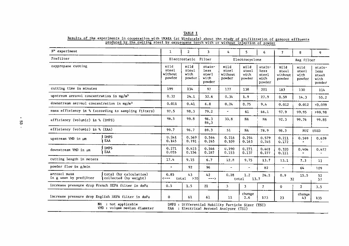
TABLE I
CJ1 CO
produced by the cutting stee 1 by oxypropane tor ch with or without i
N° experiment Prefilter oxypropane cutting
cutting time in minutes upstream aerosol concentration in mg/m3
downstream aerosol concentration in mg/m3
mass efficiency in % (according to sampling filters)
efficiency (volumic) in % (DMPS)
efficiency (volumic) in % (EAA)
upstream VMD in um I ^ S
Í DMPS downstream VMD in gm < „,.
cutting length in meters powder flow in g/min aerosol mass ( total (by calculation) in g seen by prefilter ^collected (by weight) increase pressure drop French HEPA filter in daPa
increase pressure drop English HEPA filter in daPa
1 2 3 Electrostatic Filter
mild steel
without powder
199 0.32 0.011 97.5 9Ö.5
99.7 0.241 0.145 0.271 0.055 17.4 -
mild steel with powder
134 24.1 0.41 98.3 99.8
96.7 0.569 0.191 0.415 0.156 9.15 92
0.85 43 <--- total >70 0.5
0
1.5
61
stainless steel with powder 97 32.6 6.8 79.2 96.3 86,3 89.3 0.564 0.265 0.546 0.187 6.7 96 42
> 21
61
4
njection of powder
5 6 Electrocyclone
mild steel
without powder
177 0.34 0.24 -33.8
51 0.216 0.109 0.290 0.153 12.8 -
mild steel with powder
138 1.9 0.75 61 NA
NA 0.254 0.163 0.271 0.137 9.75 -
stainless steel with powder 201 27.9 9.4 66.1 NA
78.9 0.579 0.245 0.601 0.277 13.7 82
0.28 1.2 26.2 total 13.7
3
11
3 change 2.6
7
173
7 8 9 Bag filter
mild steel
without powder
183 0.59 0.012 97.9 92.3
98.3 0.211 0.172 0.320 0.111 13.1 -
mild steel with powder
130 14.3 0.012 99.95 99.76
stainless steel with powder 114 55.2
<0.009 >99.98 99.85
NOT USED 0.569
0.404
7.3
0.639
0.472
11 64 ' 109
0.9 15.5 32
0
23
2 change 43
52 52 3.5
135 NA : not applicable VMD : volume median diameter
DMPS : Differential Mobility Particle Sizer (TSI) EAA : Electrical Aerosol Analyser (TSI)

Qxhûust
preJjltoT
Figure 1 Diagram of prefiltration test rig
C 50 "a
J g 30
%£ VD a £ o
''■'.Y'VV.*'.
(a)
•i: i V¡"¡ '.T/
! ••'•*.! II i iiniJBli
Q1 70 QCrociynamic. cJiamoÍAjr ( ü m )
Figure 2 Aerosol mass distribution in cutting 5 mm type Z2 CN1810 stainless steel (a) or 15 mm type A 33 carbon steel using
oxyacetylene torch cutting (b)
54

a doctrostatíc precipitator
V oag Xfltor Crieos bacp )
o oJßctro cyclone
A CycJono.
aerodynamic d iameter ( um ) Figure 3 - Efficiency of the cyclone, the electrocyclone, the ESP
and the bag filter made with calibrated particles between 0,15 and 10 um
Figure 4 Electrocyclone (280 m3/h)
Figure 5 Bag filter (500 m3/h)
55

Figure 6 - Electrostatic filter (800 m3/h"1
Figure 7 - View ot the connection between the English loop (at Vindscale in Hero Reactor) and our test rig
(here, with the bag filter)
Figure 8 - View of the first stage of the electrostatic filter after A hours of steel cutting with oxypropane torch and
injection of powder (experiment at Windscale)
56

3.3. Dross and Ultrafine Particulate Formation in Underwater Plasma-arc Cutting
Contractor: Heriot-Watt University, Edinburgh, United Kingdom Contract N": FI1D-0008 Working Period: January 1985 - March 1987 Project Leader: B. Waldie
A. Objectives and Scope Underwater plasma-arc cutting is a useful technique for dismantling
but produces dross and ultrafine fume particles which must be collected. The overall project aim is to improve understanding of the factors governing formation rates and characteristics of dross and ultrafine fume particles so that these by-products can be better controlled during dismantling.
The research is predominantly experimental, with supporting theoretical work on fluid dynamics of dross behaviour and on formation and behaviour of the ultrafine fume particles. Metal samples to be cut are non-active, the aim being to characterise the basic mechanisms which should be valid for active and non-active metals. Cutting is done in a hyperbaric chamber with simulated water depth up to 10 metres. The former vessel allows the influence of pressure and a water column. Part of the programme involves the development of techniques for collecting and characterising dispersed dross and ultrafine particulates.
B. Work Programme B.1. Updated literature review and analysis of data on secondary waste
(dross, ultrafine fume particles) generated during underwater plasma-arc cutting of steel.
B.2. Design and construction of a dross collection system, appropriate for underwater cutting.
B.3. Design and construction of a collection device for ultrafine fume particles appropriate to underwater cutting.
B.4. Development of TV and/or photographic techniques for underwater monitoring of the behaviour of cutting waste.
B.5. Tests on cutting of non-active stainless steel samples in hyperbaric flooded test chambers, with monitoring of dross and ultrafine fume characteristics under various cutting parameters (cutting vertically upwards).
B.6. Idem B.5., with cutting vertically downwards. B.7. Idem B.5., with cutting in horizontal position. B.8. Design and construction of a test vessel providing a 10m water depth
and monitoring/sampling devices for cutting waste. B.9. Cutting tests in the facility developed in B.8. with cutting parame
ters selected in B.5. to B.7. B.10 Analysis of the surface layer material behaviour by trace and
compound work-piece techniques. B.ll Conclusive assessment of obtained results.
- 57

C. Progress of Work and Obtained Results Summary
Underwater plasma cutting tests in the 0.66m diameter hyperbaric chamber have been done at pressures up to the equivalent of 10 metres water depth. Somewhat higher current levels are needed to ensure complete penetration at increased depth. Attachment of dross increases with equivalent water depth at otherwise constant conditions. A small but practically significant part of the dispersed material in the water is in the form of micron and submicron particles, initially in suspension. These suspended particles represent about 0.2% wt. of total dispersed material. Filtration rate characteristics of these suspended particles have been studied. No dependance of filtration rate characteristics on cutting conditions is apparent. Particle size measurements on the suspended particles show particles ranging from about 0.02 Um up to about 5 - 1 0 Urn. The smaller are probably trapped fume particles and the larger ones formed direct from molten dross. A complete weighted size distribution is difficult to obtain because of the wide range of sizes.
Rates of fume evolution have been measured from cuts in stainless steel. Variables included metal thickness, current and equivalent water depth. Progress and Results 1. Experimental Equipment and Techniques (B.2, B.3 & B8)
In the course of the experimental work, improvements have been made to the 0.66m diameter hyperbaric chamber and associated equipment. A baffle has been fitted to half the vessel length and hence volume of water to be filtered after a cut. This baffle also prevents deposition of particles on the drive mechanism. To give more accurate continuous measurement of water filtration rates, a pressurized feed vessel, and a receiver mounted on a load cell, have been introduced. A small cyclone has been fitted in the gas line to the fume filter to remove small water drops entrained in the effluent gas. The overall flow scheme with these modifications is shown in Figure 1.
Construction of the 0.6m diameter vertical vessel has been completed up to the 5m height (B.8) and tests cuts made. The diameter of the upper part of the vessel will be determined after bubble dispersion tests in the present 5m section. 2. Attached and larger dispersed dross particles
Relative proportions of attached and dispersed dross and the particle size distribution of the latter have been measured for metal thickness up to 40mm. Cutting of the 304 stainless steel was in the horizontal position (B.7). Particle size distributions of dispersed dross from 19 and 25mm stainless steel were essentially the same as from 12mm reported previously.
With increase in pressure and hence equivalent water depth in the 0.66m hyperbaric chamber, a higher current is needed to ensure cutting at otherwise constant torch conditions. This is shown in Table I for 25mm thick stainless steel. Related to this increased current requirement, there is also a tendency (Table I) for more dross to remain attached to the work piece with increase in equivalent water depth. These results were obtained at a constant mass flowrate of plasma gas (60% Ar/40% N„). The consequent expected decrease in plasma velocity with increase in equivalent water depth presumably contributes to increased dross attachment. A 30% higher gas flowrate and lower speed improves cutting of the 40mm stainless steel but there is still an increase in attached dross with equivalent water depth.
58

3. Fine dross and other particles suspended in water Besides the larger dispersed dross particles there is a smaller, but
practically more significant, quantity of fine particles in the water after a cut. Further studies have been made of the production rate, particle size distributions and filtration characteristics of these fine particles (B.7). These particles represent of the order of 0.2% wt. of total dispersed dross (Table II). Several methods of measuring the relatively small amounts of these particles have been studied. The most reliable of these involves filtration on a 0.45 ym membrane filter, dissolution of the membrane in acetone and concentration of the particles by centrifuging, extraction and drying. Results so far in the hyberbaric chamber do not suggest any obvious dependance on equivalent water depth nor any simple dependance on metal thickness.
Optical and electron microscopic examination of these particles suggest that there are three types:-1) Larger, up to 5 - 10 Urn, spheroidal particles which have probably
formed directly from molten metal at the cut face. 2) Very small, submicron, fume particles trapped in the water. 3) Intermediate size, submicron to l-2pm, agglomerated type 2 particles.
Measurement of the size distribution of these suspended particles has proved problematic due to the wide size distribution. A recently developed commercial instrument (Malvern Autosizer lie) has provided some data (Figure 2). This instrument is based on autocorrelation spectroscopy of fluctuations in scattered light caused by Brownian motion of suspended particles. The small modal size, 0.024 ym, suggests that these are fume particles which have been trapped by the water. Settling calculations suggest that other particles larger than 1 ym had probably settled out before sampling. In any event, simultaneous measurement over the full range of sizes present is difficult as signals from particles of about 1 -5 ym can swamp those from small submicron particles.
Filtration characteristics of these suspended particles are important in the design of removal equipment. Filtration measurements have been made on flat membrane filters of 0.45 ym pore size operated at constant differential pressure. Rate data for suspensions from a variety of cutting conditions are plotted in Figure 3. Specific cake resistances calculated from the slopes do not show any obvious trend with cutting conditions.
Beside producing suspended particles, the plasma cutting process also causes the water to become acidic. This is shown in Table III in terms of pH and electrical conductivity. Formation of oxides of nitrogen from the nitrogen containing plasma gas is presumably the cause. These effects are however exaggerated in the present studies because the water volume has been intentionally minimised. 4. Ultrafine fume particles in effluent gas (B.3, B.7)
Yields of ultrafine fume particles in the effluent gas from shallow water cuts in the hyberbaric chamber have been measured on a 0.22 ym membrane filter. In later runs this filter was preceeded by a cyclone to collect any entrained drops and associated particles before the filter. As shown in Table IV, the fume formation rates lie mainly in a range 20 -56 mg/metre cut length. There are no clear trends with thickness, or with equivalent water depth. Variations in the latter parameter were achieved by varying the chamber pressure. Data from such experiments will allow separation of any effects of pressure itself from those of increased water contact time when actual water depths are varied in the vertical vessel.
Particle size distributions of the fume particles are to be measured in a joint study with the SPIN Research Group of CEN Saclay.
59

Effect of C urrent an d Equivalent
TABLE 1
Water Immersion Depth on Dispersed and Attached Dross
Metal Thickness
mm
25 25 25 25 25 25 40 40
Current amps
150 163 180 180 180 180 200 200
Equivalent Water Depth
m
0.03 0.03 0.03 3.4 6.8 10.2 0.28 0.80
Metal Melted ' kg/m
0.695 ' 0.756 0.826
' 0.869 0.886 0.843 1.238 1.443
Dispersed Dross
kg/m
0.697 0.752 0.831 0.814 0.787 0.723 1.143 1.268
Attached Dross , kg/m i
% of Metal Melted
i Negligible ; Negligible j Negligible ! 0.055 6.3 0.099 11.1
! 0.120 14.2 ! 0.095 7.6 1 0.174 12.1
TABLE II
Yields of Fine Particles Suspended in Water after Cutting
Metal Thickness
mm
12 12 12 12 19 19 25 25 25 25 40 40
Equivalent Water Depth
m
0.03 0.03 0.03 0.03 0.03 0.03 3.4 3.4 6.8 10.2 0.28 0.80
Cut Speed mm/min
190 190 280 190 190 190 190 190 190 190 96 96
Current Amps
100 95 100 125 125 150 150 180 180 180 200 200
Particles S g/m Cut Length
0.669 0.349 0.338 0.418 0.353 0.180 0.778 1.532 1.203 2.102 1.766 1.709
uspended in Water % Wt.of Total Dispersed Dross
0.26 0.15 0.15 0.14 0.08 0.03 0.13 0.19 0.15 0.29 0.15 0.13
60

TABLE III
Changes in pH and Conductivity of Water During Underwater Plasma Operations
Feed Filtered Operation Water Unfiltered (0.45um
Membrane)
pH
Cutting
Gouging Plasma Only
7.6
7.6
7.8
3.54.0
3.53.7
4.1
4.04.8
4.55.1
4.1
Conductivity, yS/CM
Feed Filtered Water Unfiltered (0.45ym
Membrane)
0.8
3.0 13
1.5
3062
70117
24
1430
3348
19
T
Yields of Ultrafine Fume Particles Steel in Sh
Metal Thickness
mm
12 12 12 12 19 19 25 25 25 25 40 40
allow Water
Water Depth,m j Actual Eqüiv.l
1 i
1 0.03 0.03 : 0.03 0.03 ' 0.03 0.03 • 0.03 0.03 ! 0.03 0.03
;
0.03 0.03 ; 0.03 0.03 ' 0.03 3.4 ; 0.03 6.8 0.03 10.2 0.08 0.28 . 0.08 0.80 |
Speed mm/min
190 190 280 190 190 190 190 190 190 190 96 96
ABLE IV
in Effluent Gas from Cutt
Amps
100 , 95 100
■ 125 ■ 125 , 150 150 150
¡ 180 ; 180 1 200 200
ing Stainless
Fume Particle Yield mg/m Cut
43 32 21 37 17 20 19 16 37 33 56 52
% Wt.Total Dispersed Dross
0.0169 0.0137 0.0095 0.0123 0.0040 0.0040 0.0013 0.0026 0.0047 0.0046 0.0049 0.0041
Concentration in plasma gas
mg/m3
320 240 230 270 130 150 70 120 280 250 140 200
61

Jr? ws rutBs
PRESSURISING OAS
F*ESSU»SfO FILTRATION HOUMO VISSEL
r<Sh WA,tR
LOAD CELL — COLLtCTION SYSTEM.
50 ■•
20
10
5
2
1 +
NUMBER. HEDIAN 23.7NM
MASS. MEDIAN 46.8 NM
MEASURED 3 HOURS AFTER r\s, CUT IN 40HM STAINLESS
\ STEEL. \ \
\ \
-f- H 4 5 10 20 50 100 500 PARTICLE SIZE (NM)
Fig. 1. Schematic of underwater plasma Fig. 2. Particle size distribution of arc cutting in hyperbaric water suspended particles, chamber with improved particulate collection systems.
140
120
100
IlLl v-v. I
80 L ( S/LITRE ) I
60 -
40
20
r; cP u
o ,,<P, '■'-
3 , ¿ft* aa
s s
ES S
o *0*
3
1°
D
KorcxPiccL THICKNESS
(HH)
a
a
rs
4
25
25
25
40
40
40
40
40
PARTICULATE CONCENTRAT ION
( G / M ' )
4.71
6.67
7.57
6.33
7.52
11.96
16.02
22.55
¿**>:^8í6
.••/.Æ^s1
.*£**" .♦♦»
10 15 20 35 40 45 25 30 v-Vj (LITRES)
Fig. 3. Filtration rate data for suspended particles (AP = 0.85 atm)
50
62

3.4. In-Situ Arc-saw Cutting of Heat Exchanger Tubes and of Pipes from the Inside
Contractor: Field Automation, Paris, France Contract N": FI1D-0009 Working Period: January 1985 - April 1987 Proiect Leader: P. Thome
A. Objectives and Scope The principle of underwater metal cutting by electric arc saw
presents some similarities with the arc gouging process and electrode arc cutting. Besides its numerous other advantages as high precision work and small production of cutting waste, this method is especially appropriate for telemanipulation by robots: particularly because of small induced vibrations and cutting forces involved in this process, and by the possibility to use small dimension cutting discs allowing for high accessibility to complex areas.
The present work is mainly aimed at an adaptation of this procedure to in-situ cutting by robots, especially inside of tubes and pipes, with a special objective to dismantling steam generators and other heat exchangers in nuclear installations.
This development comprises design studies for apparatus to be adapted on special crawler or robot arms, laboratory studies of the cutting parameters, miniaturisation of cutting heads for their introduction into small diameter ducts.
B. Work Programme B.1. Development of methods and tools for internal arc-saw cutting of
steam-generator (S.G.) tubes (internal diameter of about 19 mm). 6.1.1. Design, construction and testing of a miniaturised cutting tool
for PWR steam generator channel head. 6.1.2. Development and construction of a laboratory testing bench to
check process characteristics by external and internal cutting. F.1.3. Design and fabrication of a complete device for internal cutting,
based on test results obtained under 6.1.1. and complying with in-situ working limitations.
B.1.4. Execution of performance tests on representative Inconel tubes (under water).
B.1.5. Final assessment on realistic full-scale samples supplied by EdF. 6.2. Development of methods and tools for internal arc-saw cutting of
pipes (internal diameter about 200 mm). 6.2.1. Design of a suitable crawler fcr hoisting the cutting tool. B.2.2. Fabrication of an appropriate cutting tool and laboratory tests to
determine the cutting parameters in accordance with the pipe diameter and thickness and with the tool working limitations.
6.2.3. Testing of the cutting tool.
- 63

C. Progress of work and obtained results Summary
During the reporting period, the research work has covered following parts of the work program: - Reception of the new general purpose laboratory bench (8.1.2);
Cutting parameter studies on this new testing bench; Design and fabrication of miniaturized arc-saw cutting heads for SG. tubes, ajustable on the testing bench (B.l.l.); Starting of performance tests with the new cutting head, on representative Inconel and S.S. tubes supplied by EdF (B.l.l). Starting of cutting parameters studies on thick pipes (B.2.3.);
- Design of a new cutting tool adjustable on the crawler (B.2.2.), suitable to the test results obtained under B.2.3. The Laboratory tests confirm the expected performances of the method:
high cutting velocity, no distortion of the work piece, negligible cutting forces, reduced dross formation. Unfortunately, the wear of the electrodes used so far is too strong for an industrial application. Application of arc-saw cutting in small SG tubes required more extensive work than expected. To minimize complexity and brittleness of the very first designed tool, a new miniaturized tool has been developed and is, at the moment, partially tested. This tool, designed through a new mecanical approach, is dedicated to transversal cutting.
Regarding internal arc-saw cutting of large diameter pipes, the first laboratory tests on the bench have shown the necessity to use an electrode as small as possible. Complementary tests are in progress. According to this, a new cutting tool had to be designed, with acceptable dimensions to be carried by the crawler.
Progress and Results
1. Characteristics of the new testing bench (B.1.2.) Cutting head?
- Adjustable rotation of the electrode, from 300 to 6200 rpm; 600 Amps slip ring;
- Horizontal range 95 mm., vertical range 230 mm. Rotative pallet holding the samples:
- Adjustable rotation from 2,5 to 25 rpm; - Chuck capacity up to 074 mm.; - Mercury slip ring; - Plate carrying 0170 and 0230 mm. pipe samples. Power supply delivering 100 Amps under 20 Volts, regulation by thyristor and 50Hz frequency. Printer XYT.
2. Laboratory tests (B.l.l.) Determination of the optimal dynamic parameters:
rotation speed (Vr) of the electrode, feeding speed (Vd), voltage and intensity (I), relating to the material and the wearing of the electrode, to the water flow, the arcing and kerf aspect. The first tests were made in external cutting mode with copper (Cu) and steel electrodes 018 mm, on 022,2 mm SS test-bars. For both Cu and steel electrodes, the S ratio (machining section/wearing of the electrode) rises to a maximum for Vr around 4000 rpm, and Vd around ]Oram/sec.
64 -

The best kerf aspect is obtained with a 1 mm thick steel electrode and with Vd of about 6 mm/sec. The laboratoty tests give the following relation:
I = K * p * log(Vd) where K is a constant relative to the geometry of the electrode, and p the kerf depth.
Internal cutting of 022 mm stainless steel tubes, with 015 mm electrodes (Cu, Steel, Mo): The results have shown that the electrode materia] has no influence on the cutting aspect, but the wearing of the electrode was different as the S ratio value increases with Cu, steel and Mo, in this order. By using a bevelled edged electrode, the cut is clean, but the profile wears too rapidly. A compromise can be used with a flat profile and a 0.5 mm thick electrode.
3. Design of a miniaturized arc-saw cutting head for SG tubes (B.l.l.) The transversal cutting head works "by excentration" of the
electrode (figure 1). This new tool was developed in place of the very complicated first design, and in order to be adapted on the testing bench.
A flexible Cu rod (01) holding the 015 mm electrode (02) is maintained firmly through a rotative insulated envelope (03). Excentration of the electrode is controlled by a wedge (04) on the envelope, applying on the rod. The relative vertical displacement between the rod and the envelope gives the excentration value of the electrode. Rotation of the envelope drives the perimeter of the electrode in contact with the internal perimeter of the tube (Vr = Vd).
4. Tests with the transversal cutting head, on representative Inconel and stainless steel tubes supplied by EdF (B.l.l.)
Preliminary tests proved the technical reliability of the process: The insulated envelope 018 mm can rotate up to 4000 rpm in the SG
tube sample without signifiant problems. For both tested Cu and steel electrodes, the best cutting aspect is obtained with Vr around 3500 rpm.
A 25 mm vertical course of the envelope commands the full excentration of the electrode (4 mm). The electrode is arcing with the tube sample after a 1.5 mm excentration (vertical course 10 mm to get in touch with the tube sample). During the cut, the elevation speed is about 0.2 mm/sec, corresponding to a 0.03 mm/sec excentration. A cut is achieved in about 100 sec.
Despite a theoretical excentration of 2.5 mm, sufficient to cut a 022x1 mm SS tube sample, a full 4 mm excentration is needed to overcome the wear of the electrodes. As shown by laboratoty tests (§.2), the wearing of Cu electrodes is to important to achieve cutting a tube sample. First cuts were made with steel electrodes held on a steel rod. But again, the S ratio is too low to manage cutting more than two samples with the same electrode, which is not acceptable for an industrial tooling.
Intensity never reaches more than 30 Amps, except when the electrode is sticking.
The water flow is about 5 liters/mn. Further tests with Mo electrodes will be completed and commented
on our next report.
65

5. Fabrication of the cutting head and starting of cutting parameters studies on thick pipes (B.2.2., B.2.3.)
The head for cutting internally thick pipes, as designed to be held by the crawler, has been integrated on the testing bench (see §.1) with minor modifications with respect to the tests on small diameter tubes:
the head is held vertically on a horizontal micrometrie table for excentration adjustment;
instead of rotating this head, the pipe or tube sample is rotating on a pallet.
These first tests were made with 090 mm x 1.5 mm thick Cu electrodes on a 0 240 mm x 20 mm thick pipe sample. It appeared that the penetration of the electrode cannot exceed 1.5 mm in the sample. Beyond this value, the wear of the electrode rises gradually without noticeable progress of the kerf. The same results are obtained by using a stronger power supply of up to 300 Amps. This limitation is due to lateral parasitic arcing phenomena of the disk. We must not only consider the frontal cutting section of the electrode on the pipe but also the whole surface in contact, because both lateral faces of the disk are arcing on dross and melted steel. Tests with smaller 040 mm x 1 mm steel electrodes are in progress: already full thickness cuts have been achieved even with 80 amps on static samples (Vd = 0).
A new tool has been designed which would suit the pipe crawler, using smaller electrodes (figure 2): The motor (01) driving the electrode (02) is mounted in an insulated water-proof envelope (03). A insulated gear (04) commands the rotation of the electrode axe (05) held in a shape (06) where the electrical supply (07) is connected. A Mercury chamber (08) takes place of the previous slip-ring, and its reduced size allows overall dimensions of this cutting head to be nearly the same as the previous one, for crawler adaptation.
66

04
"L
OJ
02
01
01
Figure 1: Transversal cutting head for tubes
- 67

Figure 2: Cutting head for Large pipes
68

3.5. Electrochemical Technique for the Segmenting of Activated Steel Components
Contractor: Kernkraftwerk RWE-Bayernwerk GmbH, Gundrennningen, Germany
Contract N°: FI1D-0010 Working Period: January 1985 - June 1986 Project Leader: W. Stang
A. Objectives and Scope Electrochemical decontamination has a great importance during the
decommissioning works at KRB-A. By this method a thin metal surface layer is removed due to a galvanic process in an electrolytic solution. Using the same principle, it is also possible to remove material locally (ECM-technique).
Many advantages of this method indicate that it could be used for disassembling activated components during decommissioning of nuclear power plants. In order to investigate its applicability, experiments with non-active materials from a reactor pressure vessel are carried out.
In the research programme it will be established: - which cathodes are most suitable for high cutting velocities, - which amount of sludge (waste) is produced in the electrolyte.
The work in this contract will assess whether electrochemical cutting of activated parts of the KRB-A reactor pressure vessel is a technically useful, low-cost and low radioactive dose procedure.
The experiments are carried out in an existing test facility of AEG-Elotherm in Remscheid.
B. Work Programme B.1. Modification of an existing test facility for the testing of static
and dynamic cathodes. B.2. Implementation of parametric studies and of the main test programme
on various non-active representative steel plates. B.3. Evaluation of the obtained results and elaboration of recommenda
tions for a possible application to radioactive components.
69

C. Progresa of work and obtained results
Summary
The experiments of electrochemical cutting techniques have been finished in 1985. This year the results of the research program were summarized for the final report.
By this program it has been proved that the ECM-techaique has a potential for cutting plates with equivalent material and wall thickness of a reactor pressure vessel.
In order to prove the applicability to a real reactor pressure vessel the unsolved problems should be studied at a large scale model.
Progress and results
1 . Modification of an existing test facility for the testing of static and dynamic cathodes (B.1.)
The modified facility for cutting special workpieces of reactor pressure vessels was already introduced. It mainly consisted of an operating system, a current supply, and an electrolyte recycling system. By this equipment it was possible to cut 8 non-radioactive workpieces with the dimensions of 210x107x143 mm. The basic material 22 NiMoCr37 was cladded with a 6-7 mm thick layer of stainless steel (1.4556).
2. Implementation of parametric studies and of the main test program on various non-active representative steel platea (B.2.)
The following BCM operating methods were studied: static tests interval tests dynamic tests
Depending on the operating method the following parameters were varied: - voltage
current kind of cathode cutting velocity
3. Evaluation of the obtained results and elaboration of recommendations for a possible application to radioactive components (B.3.)
The static tests are characterized by the fact that the electrode does not move in relation to the workpiece during the process time. This methode is not suited for cutting the material because of considerable passivation problems when reaching the basic material.
- 70

In the second phase the interval tests were investigated. By this method an electrode is moved towards the material at certain intervals in accordance with the metal removal (stop and go). It was established that a complete cut through a wall thickness of 143 mm could be executed without any problem in 750 minutes. The optimized cathode with a thickness of 6 mm produced a gap in the workpieces of 3 mm. The progress of excavation during the interval tests is shown in Fig. 1. The dynamic tests were carried out in the third phase and are characterized by the fact that the electrode is continuously moved towards the material. However, a narrow gap was obtained,it appeared that this process behaved sensitively against changes of electrolyte pressure and voltage. The excavation rate is shown in Fig. 2.
During the ECM-procedure the dissolved material is transferred into hydroxide which can be found in the electrolyte in fine particles having a grain size of approx. 3/urn. These particles were separated from the electrolyte by centrifuging, filter pressing and drying. The electrolyte is returned from the centrifuge and the filter press into the process circuit. The remaining waste quantity after several concentration steps is rather low. The ratio between the volume of dissolved material and the residual waste quantities is shown in Fig. 3« It was proved that the ECM-technique is basically practicable for cutting parts from the reactor presaure vessel of KRB-A. The investigation demonstrated that the interval process is the best suited procedure for this purpose. In a further step this procedure should be investigated under practical conditions for a possible application at the reactor pressure vessel (RPV). Therefore a large scale model of the RPV should be designed and built for further experiments. The following tests have to confirm that the ECM-process is suited for cutting cylindrical vessels by horizontally moving electrodes.
71

CURRENT [Al
200
1U0
i i i — 1 5 10
INTERVAL TIME
(min) -+—
CURRENT IA l
1000
500
100
10 REACTION TIME
20 [min]
•>4
EXCAVATION ImmJ
5 10 INTERVAL TIME
(mini
EXCAVATION [mm]
200 400 600 715 BOO REACTION TIME
(mini
Fig. 1: Progress of excavation and current during interval tests
Fig. 2: Progress of excavation and current during dynamic tests

WEIGHT [ kg :
36 -
10
METAL SLUDGE RESIDUES AFTER CENTRIFUGARON
RESIDUES AFTER FILTER-PRESSING
SOLIDS AFTER DRY UP
Fig, 3: Waste ratios after several concentration steps referring to the dissolved metal
73

3.6. Explosive Techniques for the Dismantling of Biological Shield Structures
Contractor; Battelle-Institut e.V., Frankfurt, Germany Contract N°: FI1D-0011 Working Period: April 1985 - September 1987 Proiect leader: H.U. Freund
A. Objectives and Scope In the decommissioning of reactor systems, the removal of heavy
reinforced or prestressed concrete structures, in which large quantities of concrete and steel have become activated during reactor operation, is considered as a major problem.
To study methods for the safe removal of activated materials without release of radioactive materials, various techniques are being considered for the cutting of concrete in which a high level of control could be imposed. In the foregoing CEC research programme Taylor Woodrow Construction (TWC), under consideration of one approach, undertook a programme of controlled cutting. During the same period, the Battelle-Institut e.V., Frankfurt (BF) also demonstrated the feasibility of an approach using "line charges" as opposed to the "point charges" used by TWC.
The present research work aims at complementing, improving and optimising the foregoing work. Extensive investigations will be executed on the adjustment of blasting parameters, material and structural effects, drilling techniques, particle distribution and on procedures for remote handling. Work is carried out jointly - based on a common and complementary work programme - with TWC (contract N° FI1D-0012).
B. Work Programme B.1. Adjustment of blasting parameters considering separation effi
ciency and fragment size. B.l.l. Effect on initiation mode - sequential or simultaneous firing
(BF). B.1.2. Effect of charge type and tamping (BF). B.1.3. Effect of charge distribution - hexagonal and parallel line arrays
- (BF). B.2. Material and structural effects. B.2.]. Effect on the geometrical shape of the structure and of the
presence of a liner (TWC). B.2.2. Effect of the reinforcement array (BF + TWC). B.3. Drilling and boring of charging holes. B.3.1. Assessment of boring by shaped charges (TWC). B.3.2. Assessment of mechanical drilling (BF). B.4. Study of the structural response of the test body and filters to
blasting in closed containment experiments. B.4.1. Response of the test body and of its foundation (BF). B.4.2. Study of the blast valve pressure distribution (BF). B.4.3. Effect of blast on air filters (BF). B.4.4. Theoretical assessment and modelling of blast effects (BF + TWC). B.5. Investigation of generated dust during blasting. B.5.1. Assessment of particle size distribution of produced rubble as a
function of charge burial depth (TWC). B.5.2. Effect of a spray system on mass and size distribution (BF). B.6. Final assessment and evaluation of results, including desk studies
on procedures for remote handling (BF + TWC).
74
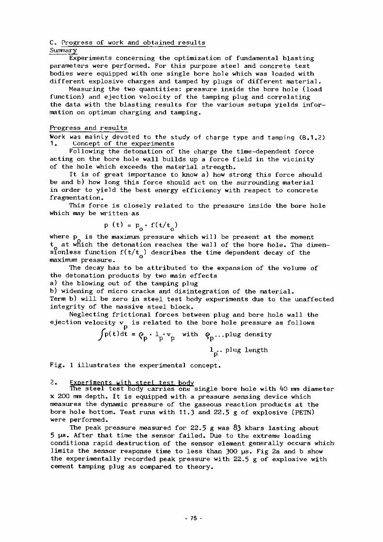
C. Progress of work and obtained results Summary
Experiments concerning the optimization of fundamental blasting parameters were performed. For this purpose steel and concrete test bodies were equipped with one single bore hole which was loaded with different explosive charges and tamped by plugs of different material.
Measuring the two quantities: pressure inside the bore hole (load function) and ejection velocity of the tamping plug and correlating the data with the blasting results for the various setups yields information on optimum charging and tamping.
Progress and results Work was mainly devoted to the study of charge type and tamping (B.1.2) 1. Concept of the experiments
Following the detonation of the charge the time-dependent force acting on the bore hole wall builds up a force field in the vicinity of the hole which exceeds the material strength.
It is of great importance to know a) how strong this force should be and b) how long this force should act on the surrounding material in order to yield the best energy efficiency with respect to concrete fragmentation.
This force is closely related to the pressure inside the bore hole which may be written as
p (t) = p • f(t/t ) o o where p is the maximum pressure which will be present at the moment t at which the detonation reaches the wall of the bore hole. The dimen-sionless function f(t/t ) describes the time dependent decay of the maximum pressure.
The decay has to be attributed to the expansion of the volume of the detonation products by two main effects a) the blowing out of the tamping plug b) widening of micro cracks and disintegration of the material. Term b) will be zero in steel test body experiments due to the unaffected integrity of the massive steel block.
Neglecting frictional forces between plug and bore hole wall the ejection velocity v is related to the bore hole pressure as follows
> p(t)dt = <J> • 1 -v with O ...plug density P P
1 .. plug length
Fig. 1 illustrates the experimental concept.
2. Exneriments with steel test hnHv The steel test body carries one single bore hole with 40 mm diameter
x 200 mm depth. It is equipped with a pressure sensing device which measures the dynamic pressure of the gaseous reaction products at the bore hole bottom. Test runs with 11.3 and 22.5 g of explosive (PETN) were performed.
The peak pressure measured for 22.5 g was 83 kbars lasting about 5 us. After that time the sensor failed. Due to the extreme loading conditions rapid destruction of the sensor element generally occurs which limits the sensor response time to less than 300 us. Fig 2a and b show the experimentally recorded peak pressure with 22.5 g of explosive with cement tamping plug as compared to theory.
75

3. Experiments with concrete test bodies Hie concrete test bodies are equipped with a cage of steel rein
forcement of 2 layers. The explosive loading is performed in the same bore hole geometry as in the steel test body. During the blasting the concrete test body is embedded into a massive steel ring in order to simulate the side stiffness.
Comparison of the bore hole pressures for steel and concrete test body réveils the effect of the concrete fragmentation i.e. reduced peak pressure, more rapid pressure decay, see Figs. 2b and c.
Correlation of cratering and damage of the test bodies depending on the mass of the explosive charge in the range of 11.3 to k'y g show an optimum around 20-30 g of explosive per bore hole when using cement plugs.
Correlation of the measured plug ejection velocities with the time integral of the measured bore hole pressure is under way for further support of the load function as prime parameter to effect the concrete fragmentation.
An overview of the experiments is given in table I.
76 -

Table I: Tests performed with single bore hole explosive charges
-J
experimental setup
steel test body
concrete test body
mass of charge
11.3 and 22.5 g
11.3, 22.5 and k5 g
tamping plug material
sand, cement, steel
cement, steel with/without wall adhesion
measured dynamic quantities
pressure in the bore hole, ejection velocity of tamping plug
pressure in the bore hole, ejection velocity of tamping plug
fragmentation
none: test body remains intact
cratering around the explosive charge, damage of various extent
^ n « ^

concrete test body
CD
steel test body
load functions
tamping plug
explosive charge
low explosive mass
high explosive mass
modified load functions
shatter cone
F i g . 1 : e x p e r i m e n t a l c o n c e p t

80
60
40
20
-
.
■
pressure Kbar
\ 89 Kbar
quasistatic pressure
10 TIME
TIME
80
60
to
20
pressure Kbar
20
a)
theory (non destructive bore hole loading)
µs
b)
steel test body
c)
concrete test body
10 Time 20 /us Fig. 2; Bore hole pressure for 22,5 g of explosive
79

3.7. Explosive Techniques for Dismantling of Activated Concrete Structures
Contractor: Taylor Woodrow Construction Ltd., Southall, United Kingdom
Contract N°: FI1D-0012 Working Period: January 1986 - March 1988 Project Leader: I. LI. Davies
A. Objectives and Scope In the decommissioning of reactor systems, the removal of heavy
reinforced or prestressed concrete structures, in which large quantities of concrete and steel have become activated during reactor operation, is considered as a major problem.
To study methods for the safe removal of activated materials without release of radioactive materials, various techniques are being considered for the cutting of concrete in which a high level of control could be imposed. In the foregoing CEC research programme Taylor Woodrow Construction (TWC), under consideration of one approach, undertook a programme of controlled cutting. During the same period, the Battelle-Institut e.V., Frankfurt (BF) also demonstrated the feasibility of an approach using "line charges" as opposed to the "point charges" used by TWC.
The present research work aims at complementing, improving and optimising the foregoing work. Extensive investigations will be executed on the adjustment of blasting parameters, material and structural effects, drilling techniques, particle distribution and on procedures for remote handling. Work is carried out jointly - based on a common and complementary work programme - with BF ("contract N° FI1D-0011).
B. Work Programme B.1. Adjustment of blasting parameters considering separation effi
ciency and fragment size. B.l.l. Effect on initiation mode - sequential or simultaneous firing -
(BF). B.1.2. Effect of charge type and tamping (BF). B.1.3. Effect of charge distribution - hexagonal and parallel line arrays
(BF + TWC). B.2. Material and structural effects. B.2.]. Effect of the geometrical shape of the structure and of the
presence of a liner (TWC). B.2.2. Effect of the reinforcement array (BF + TWC). B.3. Drilling and boring of charging holes. B.3.1. Assessment of boring by shaped charges (TWC). B.3.2. Assessment of mechanical drilling (BF). B.4. Study of the structural response of the test body and of filters
to blasting in closed containment experiments. B.4.1. Response of the test body and of its foundation (BF). B.4.2. Study of the blast wave pressure distribution (BF). B.4.3. Effect of blast on air filters (BF). B.4.4. Theoretical assessment and modelling of blast effects (BF + TWC). B.5. Investigation of generated dust during blasting. B.5.1. Assessment of particle size distribution of produced rubble as a
function of charge burial depth (TWC). B.5.2. Effect of a spray system on mass and size distribution (BF). B.6. Final assessment and evaluation of results, including desk studies
on procedures for remote handling (BF + TWC).
- 80

C. Progress of Work and Obtained Results Summary Work on the contract started only in July 1986 due to delays in
getting all contract arrangements cleared. To date work has concentrated on further investigations on work packages B1 and B2 "Adjustment of blasting parameters" and "Study of material and structural effects".
Preliminary tests have been carried out to determine the effects when explosives are placed and fired in concrete which is faced with a steel liner. Debonding of the liner and its anchoring system from the concrete is required as well as cratering of the concrete.
Test blocks have also been manufactured to enable direct comparisons to be carried out on cratering characteristics between long borehole system for placing charges and the point charge of short borehole system.
Progress and Results Effect of the presence of a liner (B.2.1.) A typical biological shield will have a steel liner on the inside
surface of the containment structure to provide an impermeable membrane. In the decommissioning of such a structure it will be necessary to remove both liner and other activated parts of the containment. To meet this requirement, investigations are being carried out to determine the efficiency with which the liner and its anchoring system may be debonded from the concrete by firing explosive charges below and adjacent to the liner.
Three preliminary firings have been carried out on a steel faced and reinforced concrete block manufactured to represent a section through the wall of a steel lined reinforced concrete biological shield. The steel plate is anchored to the concrete disc in a similar manner to a steel lined concrete structure (see Fig. 1). Starting from an optimised charge weight and depth of burial for cratering of reinforced concrete structures, a depth of burial was selected to effect a debonding of the liner from the concrete. Two further firings were carried out, in the first of which the depth of burial was reduced and in the second one both charge weight and depth of burial were changed in an effort to improve the efficiency with which the liner was being debonded from the concrete. Each test involved firing a single charge placed in a pre-prepared charge hole drilled through the steel and into the concrete beneath. The individual firings were spaced out to enable each test result to be assessed before defining the parameters for the next firing.
Test results to date have indicated that it is feasible to detach the liner and anchoring system by firing explosives (see Fig. 2). Variations in the depth of burial and/or charge weight .produced anticipated results, eg a reduction in depth of burial leading to a greater impulsive load and a larger consequential heave effect on the liner.
Further tests to investigate the efficiency with which the liner and its anchoring system may be debonded from the concrete are to be carried out in the near future. These will include the firing of groups of charges to investigate the advantages that may be gained by firing multiple charges on steel lined structures to debond the liner from the concrete.
Effect of charge distribution (B.1.3.) Two test blocks have been manufactured and these will be used to
investigate the cratering characteristics when using the two main techniques
- 81
for placing charges, ie long borehole technique where the boreholes lie in a plane parallel to the target face and short borehole technique, where the boreholes are drilled perpendicular to the target face.
In previous work by Batteile IM both techniques have been used whilst work by Taylor Woodrow 12/ has concentrated on the short borehole technique. The programmed tests in Phase 2 are intended to correlate the two series of results together and consequently increase the amount of data available for any analysis. Parameters to be varied for these tests will include the separation between charges and the depth of burial of charges.
REFERENCES /1/ Durchführbarkeit der Zerlegung des Biologischen Schilds mittels
Bohrlochsprengtechnik. Battelle-Bericht BIeV-R-65.036-4 (1983).
121 A study of explosive demolition techniques for heavy reinforced and prestressed concrete structures. Report EUR 9862 EN (1985). Fleischer C.C., Taylor Woodrow Construction Limited.
82 -

steel plate reinforcement
long bolts
concrete disc
Fig. 1 Section showing simulation of a steel lined concrete face
83

steel plate reinforcement
long bolts
; ; // /
short bolts
concrete disc
Depth of charge - 1.5D Weight of charge - W
Fig. 2. Section showing simulation of a steel lined concrete face after detonation of explosive charge
84
3.8. Prototype System for Remote Laser Cutting of Radioactive Structures
Contractor: Commissariat à l'Energie Atomique, CEN Saclay, France Contract N°: FIlD-0013 Working Period: November 1984 - April 1988 Project Leader: J. Geoffroy
A. Objectives and Scope The advantage of cutting by laser beam consists mainly in very small
induced cutting forces and in producing only small amounts of cutting waste. The principal aim of the present research is the development and construction of a prototypical laser cutting device for metal structures, which may be contaminated or activated. The system will be designed for remote operation.
An existing 3-5 kW industrial laser will be adapted for transportability and tightness in nuclear environment. The laser transport system will consist in an articulated arm for transmitting the laser beam to a remote cutting location. The arm, operating with 5 degrees of freedom in a polar coordinates system, will be capable of entering an active area through an orifice of a diameter of only 250 mm. Each articulation will be equipped with an electrical D.C. motor enabling positioning by remote command. The actual trajectory of the cutting head will be defined by practical testing.
For commissioning of the developed prototype, a series of cutting tests on typical, but non-radioactive structures as hot cells, pipework, waste containers etc. will be executed, including measurements of generated aerosols and slag.
B. Work Programme B.1. Design, construction and functional testing of a robot arm including
remote control and command, and tests on the handling of the arising laser cutting waste.
B. 2. Adaptation and coupling of the robot arm to an available laser cutting device.
B.3. Commissioning and demonstration tests of the complete facility, including laser cutting of various non-radioactive stainless steel components with handling of the arising cutting waste.
85

C. Progress of work and obtained results
Summary The detailed study of " ROLD " laser robot has been followed up during the beginning of 1986. The manufacturing of the arm has been committed to BARRAS PROVENCE Company. This work has been achieved at the end of 1986 two months later than initial planned this is due to the delivery period of some components. In parallel we have worked on the control-command unit of the robot. The industrial control unit was received at the beginning of 1986. Its structure has been modified in order to satisfy ROLD specifications. A test-bench for joints has been constructed and a mechanical qualification method has been prepared. Along the 2 semester of 1986 we began the study and manufacturing of the ROLD test mock-up and also the preparation of the coupling with a multikilowatt power laser.
Progress and results 1. Design and construction (B.l.) Definitive solutions for joint's components and detailed drawings of the arm have been carried out at the beginning of 1986. Each joint includes : - a DC motor - a mechanical speed reducer - an electro-magnetic brake - an absolute multipolar synchro-resolver - a tachometer. For space requirement reasons (external diameter 0 200 mm) the components cannot be set up in a parallel direction with the joint axis. This implies the use of beveled gear. The transmission includes synchronous belt drive or floating caliper gear (Fig. 1). The manufacturing of the arm is made by BARRAS PROVENCE Company. Mechanical structures are formed of light metal alloy foundry. Then they are machined in order to receive all electromechanical components. Fig. 2 gives a notion of the entire arm. The terminal part of the arm is designed to be disconnected by tele-manipulator. Fig. 3 shows us the mechanical tele-dismountable junction using a threaded bayonet system. On this photograph we also can notice electrical and gaseous connection. A life-size wooden mock-up has been carried out for the study of wiring and piping.
2. Control unit (B.2.) The control unit has been delivered at CEA at the beginning of 1986. We have made some modifications on it, according to ROLD robot specifications. These reconditionnings have included : - New 8635 processor boards more efficient than previously - Integration of analog-digital conversion boards for multipolar resolvers
- Integration of a magnetic-disk rack and a display - Matching the connection with ROLD standard - Matching inputs-outputs, safety contacts limit-stops.
86 -

Each set-up component has been checked. A test-bench has been manufactured to check the special counting boards. We have also prepared the mechanical acceptance test of the arm. This test concerns the static repeatability error.
3. Demonstration tests (B.3.) Moreover we have designed a special exhibition mock-up which simulates the working conditions in a hot cell. This mock-up will show the concrete thickness of the hot cell and two working attitudes of the arm; the first one would be vertical and the other would be horizontal. This mock-up is currently under construction as also the optical junction with a 3 kW power laser. (Figure 4)
87 -
- FIGURE 1 - Configuration of " ROLD " robot.
88 -

oo (O
- FIGURE 2 - Part of extremal segments 9. and GL.

ID o
- FIGURE 3 - View of a L L segments of "ROLD" robot before assembling.

DEMT LASER LABORATORY
MOCK UP HOT CELL
WORK STAND
i
i
5 KW LASER C02
HOT BOX
- f f l —
BEAM LASER DISTRIBUTION LINE
3 KW LASER C02
WORK STAND
WORK STAND
- FIGURE 4 - General view of the laser working area showing " ROLD " robot with simulation hot-cell.

?•?• Investigations of Applications of T aser Cutting in Decommissioning
Contractor: FIAT CIEI S.r.]., Torino and ENF.A, Roma, Italv Contract N°: FI1D-0014 Working Period: January 1986 - December 1988 Project Leader: B. Migliorati
A. Objectives and Scope The present research work is a follow-up of work performed in the
1979-83 research programme, where if was demonstrated that laser beam cutting has a potential for a useful application to decommissioning, due to the very reduced quantity of generated aerosols and to its possibility for remote operation (Ref.: EUR 9715).
The main objectives of the present ccrtract are as follows: execution of operational cutting tests with 7-10 kW lasers on representative materials of the Garigliano BWR, with a view to determining quantities and distributions of the generated aerosol particles, execution of feasibility studies followed by practica] applications using racrk-up components. The study will be completed with the assessment of the possibility of using laser cutting of specific components, considering the future decommissioning of the Garigliano BWR.
B. Work Programme B.1. Characterisation of aerosol arisings from laser cutting. B.l.l. Execution of cutting tests on materials representative of Gari
gliano PWR components, such a¡= stainless steel, carbon steel and concrete.
B.1.2. Determination of aerosol quantities and distributions, with special attention to small particles (diameter < 0.5 pm).
B- 2. Assessment of the applicability of remote operation laser cutting of specific Garigliano BWR components.
B.2.1. Execution of feasibility studies for remote laser-cutting. B.2.2. Qualification tests or. real-size mock-up components of the Gari
gliano BWR.
- 92 -

C. Progress of work and obtained results
Summary The instrumentation that will be used to characterize the aerosol has beer, tested using plasma torch. The tested instrumentation system has beer, used on a 2 kW laser source(B.1). Assessment of the applicability cf remote cperation laser cutting of specific Garigliano BWR components(B.2). During the last year the study of laser beam propagation for a selected range of distance has been carried out. After that the optical system for guiding and focussing radiation energy has been designed and the cptical-mechanical components for the short distance have been realized. Besides the thernal blooming problem has beer, considered and quantified with particular attention on attenuation coefficient and laser pcwer density. Finally some preliminary experimental cutting tests have been carried out on AISI 304 and FE 42 C sample using a 5 kill laser.
Progress and results 1. Characterization of aerosol arising from laser cutting (B.1).
Sampling difficulties and prcblem representativeness related to particles (chain-like aggregates) produced in cutting materials by means of high temperature techniques have required preliminary tests on the instrumentation used to characterize this type of aerosols. As a first step tests have been performed by using a plasma torch as an aerosol generator to validate instrumentation and sampling lines. Among the instruments tested (filter systems, Condensation Nucleus Counter, Electrical Aerosol Analyzer (EAA), Piezobalance) only the EAA has shown difficulties in data interpretation because of fragmentation cf particle aggregates through its laminarization grids and because of the unforeseeable charging function of the chain-like aggregates. In tab. I an example of the increase of particle number concentration obtained from EAA sequential samples on the same aerosol is presented. As a result of this first part of work the sampling and dilution system have been redesigned in order to avoid dynamic stress on particles and narrowings. Particular efforts have beer, made to characterize particles below 0 . 5 o m bcth in diffusive diameter and in specific metal mass content. A special arrangement has been studied to evaluate interception losses in diffusion batteries. A prototype cf a sampler able to deternine the specific metal content of ultrafine particles has been projected and tested. The new sampling and instrumentation arrangements have been tested in laser cutting of steel (AISI 304 and FE42C). A 2 kW laser source and a new cutting box have been used. At least 40% in mass of the aerosol is related to particles below 0 .-. um.
- 93 -

A relevant preliminary result concerns the charge in metal corrpesition of particles in comparison * it!, the bulk material. In table II, as an example, the ratice Cr/Fe, Ni/fe for particles > 6 pm, < 0 .4 ̂j.n obtained by ELAX microanalysis are reported. As a reference the same ratios obtained by the same method for the bulk material are shown.
2. Assessment of the applicability of remote operation laser cutting cf specific Garigliano BWR components. Execution of feasibility studies for remote laser-cutting (B.2.11 To initiate the new research programme related with laser cutting of thick material, it is necessary to posses the source characteristics of CC¿ high power CW laser that will be mainly used for the resetuoi. The long distance propagation study is essential for the continuation of the research and can be based on the beam gaussion hypothesis. Combining a theoretical and an experimental procedure it is possible to obtain some information either on the beam quality during propagation and en the beam quality in the working position. For this purpose it is necessary to know some beam parameters, depending on the optical oscillating cavity, such as the multimode coefficient, the diameter and position of the waist, apart from the characteristics of the optical elements used for radiation guiding and focussing. A procedure example, for obtaining the useful parameters, has been developed considering a Spectra-Physics laser mod. 975 with a so called welding/cutting cavity. Using these data, on a computer programme developed for this purpose, it has been possible to go en with the design of an optical system able to collimate the laser beam and, consequently, to have uniform focussing properties over the selected working range (5-30 m). Besides the thermal blooming problem end its effect or. the propagation energy has been considered. In particular it was calculated the beam energy attenuation depending on absorption coefficient, power density and wind across the radiation. The results demonstrate that it is important to have dry gas at small velocity across or along the propagation direction in order to reduce the distortion and attenuation expecially for leng distance and high laser power density. Finally some preliminary experimental tests have been carried out to verify theoretical assumptions on the optical characteristics.
94

TABLE I Particle number concentration obtained by EAA sequential sampling on same aerosol
time min.
5 6.3 8.2 10.1 11.9 13.8 15.6 17.5 19.3 21.2 23.0
p/cm
86100 147000 151000 130000 134000 122000 136000 107000 85000 110000 123000
TABLE II Cr/Fe, Ni/Fe ratios in particles obtained in laser cutting of AISI 304 steel
Cr/Fe Ni/Fe
>6 µm .38 .09 <. 4 µm .16 .35
bulk ma te r i a l .27 .10
95 -

3.10 Spreading and Filtering of Radioactive By-products of Underwater Segmenting
Contractor: Universität Hannover, Hannover, Germany Contract N°: FI1D-0036 Working Period: May 1986 - December 1988 Project Leader: F.W. Bach
A. Objectives and Scope It is important for thermal and mechanical underwater cutting of
radioactive metal components, to provide for an efficient collection of the arising cutting by-products, thus avoiding a reduction of visibility by suspended particles and reducing the contamination of water and the radiation level at the water surface.
This work aims mainly at studying various filter systems for efficient collection of cutting by-products in air and water, combined with an in-depth analysis of their distribution and quantities as function of cutting method (grinder,- plasma torch) and cutting material (stainless steel, cladded carbon steel, aluminium).
Cutting tests will be executed on non-radioactive samples. The work will be concluded with proposals for the most appropriate air and water filter systems for underwater cutting of radioactive materials.
B. Work Programme B.1. Modification and adaptation of the existing test facility for the
provided work programme and purchasing of supplementary instrumentation.
B.2. Selection and definition of the main parameters for cutting tests with grinders and plasma arc torch.
B.3. Execution of the test programme on the distribution and concentration of particles arising in air and water with various filter systems.
B.4. Assessment of the efficiency and effective standtime of air filters and water filters.
B.5. Chemical analysis of the cutting by-products, found in air and water.
B.6. Conclusive assessment for an optimisation of filter systems for underwater cutting.
96 -

C. Progress of work and obtained results
Summary Thermal and mechanical underwater cutting of nuclear components leads
to cutting by-products, which stay in the water or get into the atmosphere depending on particle size and density. These materials have to be collected safely to protect the operating personnel and to guarantee a simple process cycle. The plasma arc cutting (for plates up to 60 mm thickness) and the grinding technique (for plates up to 20 mm thickness) will be tested and developed. Two measuring sections are constructed to collect the cutting by-products arising to the atmosphere and those staying in the water. First results show the process parameters for cutting stainless steel by plasma arc, which have to be used in further cutting tests. A comparison is given between the particle size distribution of the solidified kerf material settled in water after cutting stainless steel and carbon steel by plasma arc.
Progress and results
1. Modification and adaption of the existing test facility (B.l.) The cutting tests will be done in a water bassin with a volume of
18 m3 and a working area of 4m x 2m x 1.5m. The plasma equipment is a 100 kW power source with a tipped electrode plasmatorch. The used plasmagas is a mixture of argon and nitrogen. The grinding machine is driven by compressed air. The output power is 1.2 kW. An overview of the test facility is shown in figure 1. The particles arising from the water are collected with a suction hood which is installed concentrical to the plasma torch respectively the grinding tool. The flow of ventilation is usually 3000 m3/h so that the sampled particles do not separate in the suction pipe on their way to the measuring station. The analysis of the particle size and the particle size distribution will be done by an electrical aerosol analyser in the range from 0.01 urn to 1.0 urn in eight size classes. This analysis can be done on-line. A low pressure impactor is used to confirm these results and to get the particles for the following chemical analysis. The impactor allows the specification of the particle size distribution in the wide range from 0.016 urn to 16 urn in eleven classes. It is not possible to measure the particles in that low concentration expected after filtering with the electrical aerosol analyser. Therefore a condensation nucleous counter will be used to determine the particle concentration at low levels and in this way the efficiency of the filter system. The ventilation system allows a flow up to 6000 m3/h so that various kinds of filter systems can be used. An automatic flow control system guarantees a constant flow.
The analysis of the particles remaining in the water is done in another part of the test facility. The principle is shown in figure 2. Both cutting procedures produce a lot of particles which suspend in the water or settle to the ground of the bassin. The suspended particles are pumped out together with the water. A pump with by-pass and flow control up to 10 m3/h allows the testing
- 97

of different filter constructions and filter sizes. The analysis of the filter efficiency will be done by taking water samples before and behind the tested filter. The samples are filtered with special filters of a well known quality. The weight difference is equivalent to the testfilter efficiency. The particle size analysis will be done by electron - microscopy. The determination of the particles settled to the bottom of the bassin is done by sieve analysis.
2. Determination of the cutting parameters for plasma arc cutting (B.2.) The cutting parameters for the underwater plasma arc cutting process
are given in table I. The result is, that it is useful to follow some important rules with the aim of reducing the quantity of the generated particles. The particle emission to atmosphere is decreasing with:
- low concentration of energy in the plasma arc
- high cutting speed
- low current and electric power
- large nozzle.
The cutting parameters for stainless steel shown in table I give a combination of good cutting results with a minimum of cutting particles in the atmosphere.
3. Analysis of the cutting by-products (B.3.) In the first work stage a sieve size analysis is done of the settled dross particles after plasma arc cutting. The results are shown in figure 3. Obviously there is a rise of the large particles with increasing thickness of material. This effect is more significant in the dross of the mild steel. The form of the particles is rather globular. A comparison of the particle emission of the plasma arc cutting and grinding is the aim of the next research period.
98

Table I Parameters of the underwater plasma arc cutting
Parameters of the Underwater - Plasma - Arc - Cutting
material: stainless steel (1.4301); waterdepth: 500 mm
Parameter material thickness
10 mm 20 mm 30 mm 40 mm 50 mm 60 mm
nozzle diameter
nozzle-workpiece
current
voltage
argon
nitrogen
cooling air
cutting speed
mm
mm
A
V
1/min
1/min
1/min
mm/min
2,0
6,5
210
120
16
9
70
1300
2,5
6,5
250
120
22
11
70
700
3,5
6,5
410
130
36
18
70
550
3,5
6,5
420
130
36
18
70
330
3,5
6,5
430
130
36
18
70
260
3,5
6,5
450
130
36
18
70
200
1 Waterbassin with x-y-z-manipulator 2 Plasma torch with suction hood 3 Supply air filter 4 Measuring point 5 Electrical aerosol analyser
3 £
RÌ \ 8
6 Impactor 7 Filter 8 Condensation nucleous counter 9 Exhauster with flow control
Fig. 1 Filter test facility for particles in atmosphere
99 -

1 Water bassin for plasma arc cutting and grinding
2 Filter for pump protection 3 Pump 4 Excess pressure valve 5 By-pass
6 Pressure gauge 7 Sample taking valve 8 Filter unit 9 Water meter
10 Flow meter 11 Valve
Fig. 2 Filter test facility for particles suspended in water
ST 37
^
A
m m
11
m
&
s.
20 30 40 SO =0
plate thickness mm]
[%] '
= 0
so
to
3C
20
n %
'A
% %.
//
1.4301
Ufi ■] 2o 3o io so =0 [mm]
plate thickness
^ \ < 2 m m </^2-6 mm >6mm
Particle Size Distribution of the Solidified
Kerf Material settled in Water
Fig. 3 Particle size distribution of the solidified kerf material settled in water. Stainless steel (1.4301) Mild steel (St 37)
100

3.11 Development of a Prototype System for Remote Underwater Plasma-arc Cutting
Contractor: Commissariat à l'Energie Atomique, CEN Cadarache, France Contract N°: FIlD-0037 Working Period: May 1986 - January 1989 Proiect Leader: R. Léautier
A. Objectives and Scope Based on an extensive foregoing experience with underwater plasma-
arc cutting, the present contract is intended to further develop this technique with the following objectives: - remote and automated cutting of complex and thick-walled metal struc
tures; - evaluate the physico-chemical status of the water; - minimise the generation of cutting by-products.
Cutting tests are executed both with non-radioactive and low-level radioactive samples of stainless steel.
B. Work Programme B.1. Modification of the presently available motorised cutting table,
allowing for the dismantling of more complex structures. B.2. Execution of cutting tests aimed at optimising the main cutting
parameters. B.3. Final adaptation of the cutting table, based on the experience
gained in working step B.2. B.4. Execution of cutting tests on non-radioactive stainless steel, aimed
at a parametric study of the quantity and distribution of the arising cutting by-products and of the evolution of the physico-chemical status of the water.
B.5. Preparation, facility adaptation and execution of cutting tests on radioactive steel, including the preparation of an activity balance of the gaseous and liquid cutting by-products.
B.6. Conclusive assessment of the potential for industrial application of automated plasma-arc cutting of radioactive components.
101
C Progress of work, and obtained results Summary Work was not started until june 1986, alter the torch and its motorized holder were adapted for heavy gauge cutting in vertical and tilted positions and for cutting complex structures. This work has been concentrated on the topic of work package Bl B2 B4 due to testing opportunities. Two cutting tests only were carried out in 1986 and complex shape cutting tests are planned to continue in 1987.
Progress and results
1 • Modification to the existing motorized table with a view to cutting more complex structures (Bl)
The motorized holder driving the torch in a continuous displacement at variable speed along the X, Y,Z, 0 axes has been modified. The purpose of these modifications has been to make it possible to cup heavy gauge, tilted and jointed of various thicknesses, with water sheets in between and having the shape of horizontal cylinders. Also, the torch has been modified to make the slag return effect negligible in order to avoid adverse arcs destroying the torch tip and the nozzle. The characteristics of this arrangement are summarized in Fig.l and 2 and under Table 1. The first application example was the cutting of a reactor tank model. This model (See Fig.3) was comprised of a stainless steel tank welded to spacer channel bars separated from the concrete structure by an expanded metal sheet. The second example was the cutting of a reactor primary pump bearing. This bearing was comprised of a stainless steel sleeve of 400 mm in outer diameter. With thickness changes (25 mm mean thickness) and stellited surface protection.
2. Execution of cutting tests aimed at optimizing the main cutting parameters (B2)
These tests were carried out using a 600 A torch and with various plasma generating gases, pure argon, argon/hydrogen mixture, argon and water vortex, nitrogen and water vortex under a water head of about 2 metres. The material selected was stainless steel plates and, in order to ascertain the repeatability of the process, successive lengths of 1 500 mm arranged vertically and tilted were cut. An endurance cutting test was carried out over several successive lengths into an optimum plate thickness of 70 mm, without damage to the torch nozzle. A thickness of about 90 mm can be cut but with frequent torch nozzle changes. Pure argon has been finally selected and has given the best results in our testing conditions. Using an argon/hydrogen mixture, at identical power and speed, results in a wider cut and therefore in more slag. In addition, using hydrogen gives rise to fumes adverse to safety. Using argon and nitrogen gases with vortex demands roughly twice as much power for a speed gain of about 20 mm/m in. and, in these conditions nozzles get quickly damaged. Tilting the tool, as much as 15°, can make up for cutting lag but does not improve cutting quality significantly. The parameter optimizing results are given under Table 2.
102

3- Execution oí cutting tests on non-radioactive stainless steel, aimed at a parametric study of the evolution oi the physico-chemical_ status of the water (B4)
Over the duration of these tests the evolution of the following parameters were surveyed pH> conductivity, turbidity and elements likely to emulsify when stainless steel is being cut (See Fig.4) pH is 5-75 at time 0 and increases regularly up to neutrality. Resistivity from an initial value of 8 x 10 ./\_cm, decreases down to 2,4 10lo. cm. The turbidity values messured are not significant due to the large size of the emulsified particles (about one mm) and to the importance of the light absorption phenomene Besides, experience shows that settling is quick. The elements contained in the water are in the form of iron hydroxides in suspension; the water remains pure and there is no significant presence of soluble elements.
Table I Characteristics of the modified device
Translation along Translation along Translation along Rotation 0 about vert, axis Rotation 0 about hori. axis
X z Y
linear linear linear
Angular
Angular
speed: speed : speed:
speed :
speed:
~Y 1 4
to to to
25 80 50
55
33
cm/min cm/m in cm/min
rev/min
rev/min
Travel: Travel: Travel:
Alpha:
Beta :
100 170 110
360
360
With displacement display Motorized control Torch/Surface gap regulation :
. by servo-mechanism controlled by the arc voltage, for thicknesses<25 mm,
. by spring-loaded system fitted with reglage balls, for thicknesses / 25 mm.
Table II : Cutting parametter optimizing
Material Plasma - generating gas Torch tilt in relation to the surface being cut Arc power Arc voltage Arc current Nozzle diameter Sharp electrode diameter Argon output Working speed Torch/Surface gap Permissible oscillation sideways Mean cut width
Stainless steel Argon
0° between 90 and 105 kW between 180 and 190 V between 500 and 550 A 4 mm 5 mm 170 1/min 70 mm/min 8 mm
+ 1 mm 10 mm
103
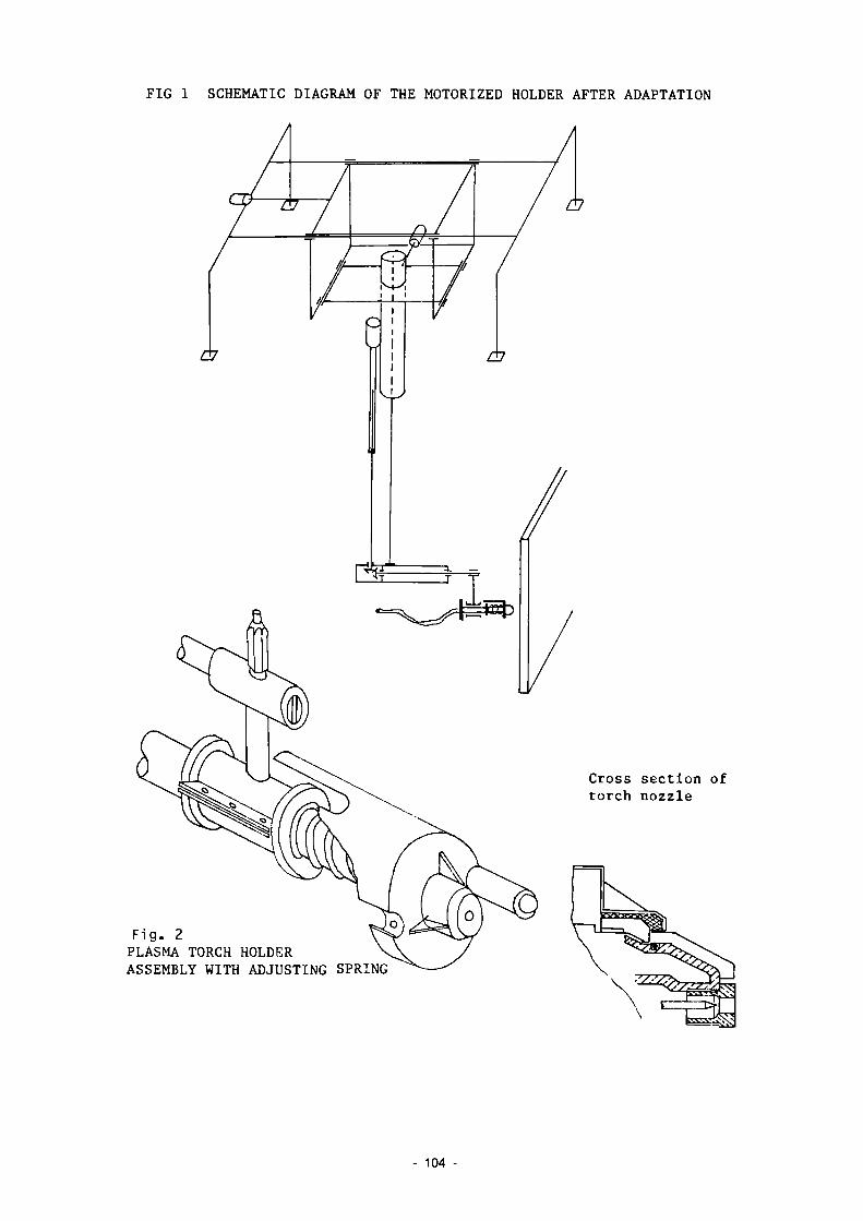
FIG 1 SCHEMATIC DIAGRAM OF THE MOTORIZED HOLDER AFTER ADAPTATION
Cross section of torch nozzle
Fig. 2 PLASMA TORCH HOLDER ASSEMBLY WITH ADJUSTING SPRING
104 -

Fig. 3 REACTOR TANK MODEL
lo
.. lì 4= i 3oo
Elements conta ined ( Fe mg/l )
R e s i s t i v i t y x l O ^ J t cr
Time In minutes
EVOLUTION OF WATER PARAMETERS
105 -

3.12 Remote Measuring and Control Systems for Underwater Cutting of Radioactive Components
Contractor; Rheinisch-Westfälische Technische Hochschule Aachen, Aachen, Germany
Contract N°: FI1D-0039 Working Period: April 1986 - December 1988 Project Leader; P. Drews
A. Objectives and Scope Decommissioning of nuclear installations requires special techniques
for the dismantling of components. Cutting of the higher-level radioactive components is preferably performed under water. To assure adequate cutting quality, some essential problems remain to be solved, such as adaptive parameter control, exact positioning of the cutting tool and control of cutting actions under water. Suitable control systems and special sensors have to be made available.
The principal aim of this research is to contribute to high-quality cutting under water by the development and application of innovative control systems and sensors appropriate for a wide range of dismantling tasks in nuclear installations.
The developed system will be tested by application to various underwater cutting procedures in collaboration with Universität Hannover (contract N° FI1D-0036).
B. Work Programme B.1. Design and assembly of an appropriate system for underwater work
piece recognition, including optical sensing, image processing and analysis, followed by practical testing with various cutting techniques.
B.2. Specification, hardware and software development for remote control of the cutting tool, providing for automatic positioning and collision avoidance.
B.3. Development of a system for the control of the cutting action, including hardware and software, and subsequent testing of a prototype.
B.4. Development and testing of an adaptive control system, assuring optimum cutting conditions for varying cutting parameters (nature and thickness of material, cutting speed and length).
B.5. Conclusive assessment of obtained results and identification of remaining tasks.
- 106

C. Progress of work and obtained results
Summary Practicable methods for dissection of nuclear components are cutting
by compressed air driven abrasive-wheel cutting-off machine and plasma cutting under water. The advantages of the first method are high cutting speed, the possibility to cut pipe and insulting layer simultaneously and low costs of the system. In reporting period problems by selection of the optical sensor system for cutting control were discussed and considered by construction of the sensor system. Further sensor tasks and functions of the controlling system were defined and a control system based on microcomputer technology as well as different sensor principles were presented. The laboratory manufacturing of the process control system is started.
Progress and results
1. Workpiece recognition under water (B.1.) Dismantling in a radioactive area under water must be remote con
trolled under simultaneous optical control by an underwater-camera. This optical control is rather difficult becausethe abrasive-wheel cutting-off process generates a lot of dust and floating particles, so water clouding, dispersion effects, a minimum of contrast and blurred contour by the camera picture are observed. Further more the refractive index of 1.33 from water results in a smaller picture angle and the influence of optical filtration by water produces reduction of total transmission and also a shifting of transmission from spectral ranges by increasing observation distances. For this reason the following points must be considered for the design of an optical system for workpiece recognition under water : - adaptation of the workpiece recognition system near the workpiece - harmonizing from sensitivity of the optical sensor (tv-tube, photodiode, MOS-condensator) to the optical filtration effect of water and also a suitable spectral emmission range of the light spots for object illumination
- radiation resistance - compressive strength, waterproofed isolation - sufficient resolving power of the optical sensor
Figure 1 illustrates on the left side the correlation between optical filtration effect of water and the choice of an optical sensor with suitable spectral sensitivity. The right side of the figure presents which innovative workpiece recognition systems perform in process automation.
All important aspects are considered by the optical sensor system, which is intended for studies to workpiece recognition.
2. Specifications to control cutting instrument positioning considering sensor informations from the tool area and application of handling systems or robots; control of cutting action (B.2.,B.3.) The whole projected control system contains the process control
computer with opto-couplers and interfaces, components for storage and documentation, a system for controlling the cutting process by sensors and also an improved system for workpiece recognition, figure 2.
The handling systems for the experiments with the cutting machine is a three-axes-manipulaõor, attache! to a water basin. The abrasive-wheel
- 107

cutting-off machine will be adapted to the z-axis; in dependence on adaption horizontal and vertical cutting will be possible.
The important cutting parameters of the abrasive-wheel cutting-off method are : - rotation speed of the abrasive-wheel - feed speed - material thickness - the actual diameter of the abrasive-wheel - the distance between tool and workpiece
For cutting process control now a microcomputer system is designed and now is in manufacturing phase. This system will be able to control the actions, like - controlling of the handling system - starting activity of the sensors - controlling of cutting parameters - controlling of sensor signals and - documentation. A general survey of the designed structure of the control system gives figure 3. Shown are the components of the microcomputer system and the handling system and also the integration of necessary sensors. There can be : - a measurement system for registration the attrition of the abrasive-wheel
- a system for distance registration between tool and workpiece - a system for control ling the feed pressure - a measurement system for cutting control.
Basically, sensors come into question as measurement systems which are based on different physical characteristics, figure h. For the above mentioned controlling tasks sensors are selected and provided. These systems now will be tested as to their practicability and application limits. The laboratory manufacturing of the total process control system based on microcomputer units is started.
108

100
%
75
i - 50 > a OJ i/i
a, 25
ro CU
r.
"Ţ I
1 \ "~s \ \
\
\
\
Optical sensor. vidicon '
1
\ \
\ \ \
N
Water -
\ \
\
\
\ \ \
300 WO 500 600 700
Wave - length nm
100
%
75
50
25
900
Workpiece recognition syster
0= =Q
Options ■
- identification - Planimetry - Detection of edges - Defection of the angle of
rotat ion
Figure 1 : Area adjusted workpiece recognition syst ystera
Process control computer wilh opto-Couple rs ond interfaces, components ior storaaes and documentations
Cutting process and Sensor systems
Workpiece recognition sysle
Pr in ter
r Rotation speed normal value Abracive-wheel roí spoed nomeai valu-: SWt in^ measurement system activity
- Emergency stop
C , 1 ' ' \ m r imelsrs T (v., n ' - ' ni j ienai s, )
• DiS'anci actual value
L Attaint'U^tti rol Spi'cd ] j t j c i l va lue ' / i b r a S i v í - w n i f l d i a m e t e r Lu " i i l a i C C loolsy s t e m - w o r kp .ece
L <
Floppy ■ D s
'-1. " J I U
• . • o - Ai i r * Too • Fee • L U '
re n-e.-i* Sy $\cm
p o s i t i o n i n g 'Uon o í f\"t a t r a s
d . s i a ^ C í Cont ro ^ Coniroi ling Contro)
ter.
i v c - v
ll.nq .■heel
Figure 2: Sensor based control system for abrasive-wheel cutting-off process under water
- 109 -

CPU ROM EPROM
C
RAH Monitor
Video -Controller
Floppy
.í <
Printer
Î Plotter
f ! . EEE-Bus >
% VIA I/O
Keyboard
PIA T/Õ'
î> Central - Bus
3*0pto-couplers D/A-Converter Impulse counter
Stop-switches reference -point-switch
Servo amplifier
Input/output
I
Sensor -interface 1
( B ) (M
Periphery
I 1 L.
3 = Brake . M = Motor , T = Tachogenerator , G= Inkr encoder
Sensor-inter'ace n
Sensor n
Figure 3: Hardware structure of the control system
sensors
tactile
mechanical : feelers with - wheels -balls - fail wheel -slide blocks
non-tactile
measuring system - inductive - capacitive - pneumatic - acoustic - optical
Figure h: Sensors with mechanical and other different physical characteristics
110 -

3.13 Removal of Concrete Layers from Biological Shields try Microwaves
Contractor: Building Pesearch Establishment, Carston, United Kingdom
Contract N": FI1D-0040 Working Period : May 1986 - December 1987 Project Leader: A.A.B. Musarmif
A. Objectives and Scope The removal of the activated layer of the reinforced concrete
biological shield of a nuclear reactor is an important operation in the decommissioning of nuclear power stations. The main objectives of this research are: - to undertake a series of studies and trials in order to assess the
application of microwaves in the controlled demolition of concrete biological shields of nuclear reactors and
- to undertake a feasibility design ard cost study of a remotely operated prototype breaker by microwave action. For this, former work on microwave concrete spalling will be re
assessed, and a series of laboratory trials on important parameters, such as appropriate power and frequency, useful applicators etc., will be undertaken. The results of these parametric studies will be applied to laboratory-scale tests into spalling the top 150-200 mm section of a reactor representative concrete block.
The study will result in the conclusion whether controlled removal of radioactive concrete layers by the application of microwaves will have a realistic potential for large-scale application to biological shield of nuclear power plants.
B. Work Programme B.1. Detailed literature search on existing microwave techniques. B.2. Theoretical analysis and computer model studies on the optimisation
of power and frequency levels. B.3. Studies on the optimisation of launching techniques for the transfer
of microwaves to the concrete wall. B.4. Theoretical analysis and computer model studies on the effect of
steel reinforcement on the induction heating. B.5. Laboratory-scale high power trials for spalling the top 150-200 mm
section of a representative concrete block. B.6. Feasibility studies for a design of a remotely operated prototype,
including cost estimations.
- 111

C. Progress of work and obtained results
Summary A limited amount of work has been carried out, reviewing previous
work and preparing for the high power tests. Reviews of previous work indicate favourably that concrete may be spalled using microwaves. The careful design of the application and selection of the angle of entry of the microwaves into the concrete appear important. Concrete details of biological shields for Magnox type reactors have been obtained and preparation of equipment for high power tests are underway. Progress and results
1. Literature search IB.1) References on previous work in this subject area have been obtained
through searches carried out using computer data bases. It has been found that some related work in microwaves has been undertaken not just at BRE but also in France, Japan and USA with applications into rock and concrete breaking and road maintenance.
The prototype unit developed at BRE in late 1960's operated at 2450 MHz and had a maximum heat capacity of 5 kW. The main object was to propagate linear cracks in concrete slabs and spalling or fragmentation was not encouraged. Records however show that tests carried out using a 25 kW capacity 892 MHz generator resulted in the fragmentation of concrete, causing craters 150 mm deep, 500 mm in diameter at a power output of 9 kW. The heating time is not available. The fragmentation is described as being the result of an explosion, indicative that pieces of concrete were dislodged from parent block of concrete.
Work on microwaves, carried out in Japan upto late 1970's is reported by F Okada et al /1 / and Y Kasai /2/. Prototype units operating at 915 MHz of upto 60 kW power outputs are described. The importance of free water in concrete is emphasised since heat generated by microwaves is proportional to the dialectric constant of the material, the value for water being 10-20 times larger than the value for aggregate or cement. Hence totally dry concrete cannot be fractured by microwaves. Tests carried out indicate that fragmentation occurs when the concrete temperature reaches 150 °C and that it is limited at any one time to a depth of 10-20 mm. The depth of fragmentation may be increased with increased irradiation time. However, the efficiency of demolition will decrease after a time if irradiation is maintained over the same point. It is reported that the weight of concrete removed increases proportionally to the square of the applied microwave power making microwaves more efficient at higher power levels. References detail precautions to be taken to prevent possible damage to the magnetron from reflected power. These will be studied in greater detail as part of preparations for the high power tests.
Work carried out in France (0NERA/CERT, Paris) is reported on by Thourel /3/. The paper is a brief report on experimental studies into concrete breaking using microwave heating. The major mechanism of failure is identified as the heating, to supersaturated steam, of free water and water of crystallisation in concrete. Concrete made from a variety of aggregates were irradiated by microwaves of frequencies in the range of 1-22 GHz. The most effective frequency was identified as 2.4-2.5 GHz.
112

Work on microwaves carried out in USA for road maintenance is reported on by L Boyko et al /H/. Although work on road maintenance may appear not to be directly relevant to concrete breaking, the report is extremely useful in giving details of equipment design, and theoretical and practical considerations of microwave energy application.
The report discusses the influence of the dialectric properties of materials and the mechanism by which microwaves energy is absorbed. It highlights inherent power losses in the system due to insertion and mismatch losses as well as losses due to partial reflection from irradiated material. It discusses how reflected power loss may be minimised. A series of calculations are presented giving values of power absorbed (w/cm3) in the irradiated material and the resultant temperature rises. The importance of designing an effective applicator is discussed and advantages of a 'leaky wave' type of applicator in terms of more uniform energy distribution into the irradiated material outlined. These are important considerations and should prove useful in the present study when preparing for the high power tests.
2. High power trials (B.5) It has been decided that Magnox type reactor biological shield
would be adopted as a model for the trials. These are the first generation reactors and upto nine Magnox reactors in Britain will be candidates for decommissioning in the next 25 years. Typically the dimensions of the shield are 25 m x 25 m x 30 m high and 2 m thick. The shield is reinforced, the reinforcing layer 100-150 mm from inner and outer surfaces of the shield. The reinforcement consists of a grid of horizontal 28 mm diameter bars at 150 mm centres and vertical 25 mm diameter bars at 300 mm centres. Typical concrete mix is given as 20 mm crushed limestone aggregate, sand, portland cement and water in the proportions 3.19:2.59:1.00:0.6 giving a cement content of 300 kg/m3 and minimum compressive strength at 28 days of 50 N/mm2. It is known that in other concrete mixes natural aggregates have been used.
An aspect of some significance to the high power trials is the presence of free and crystalline water in the concrete under irradiation. While the reactor is operational, the relatively high temperature (60 °C) and low relative humidity (10Í rh) on the reactor side of the shield, while not affecting the crystalline water, will result in the evaporation of free water. However at the time of the decommissioning, anticipated at a minimum of 15 years and maximum 100 years after reactor shutdown, concrete would have absorbed some moisture-. Therefore the free water content of the test blocks for high power trials will be limited to reflect this factor.
The high power tests will use a 25 kW (max) power output microwave generator operating at a frequency of 896 MHZ. A stainless steel tank with a microwave seal lid will be used as the test chamber. The wave guide will enter the centre of one side of the tank at an angle, in the downward direction. This is to minimise reflected energy and the quantity of dust ejected from the block getting into the wave guide.
A 600 mm cube, reinforced concrete block, modelling a segment of the shield will be used for testing. The block will be lowered into the tank
- 113

and the microwave irradiation directed at a vertical face. The angle of entry of the microwaves is yet to be decided.
The tank will have ports cut into it so that the tests may be monitored through these using lights and a video camera. Discussions have been carried out with the decommissioning section of CEGB, as to the optimum depth of concrete to be spalled. Since the reinforcement is more activated than the concrete, there is merit in exposing the reinforcement so that it can be removed separately. The high power trials will therefore attempt to expose the reinforcement, this requiring the spalling of 100-150 mm of surface concrete.
References /1 / OKADA, F. et al., Journal of microwave power (Canada), 10 (2),
pp 171-80, July 1975. /2/ KASAI, Y., European Demolition Association/RILEM Conference, June
1985, Proceedings 1. /3/ TH0UREL, B., Electron and Fis. Api (Spain), first Spanish-French
Conference on microwaves, Madrid, 21-25 May 1973, Vol 16, No 2, pp 128-30.
/¡Ì/ B0YK0, L.L. e t a l . , SURC-TR 76-052 (1976) .
114

3.14 Adaptation of an Existing Air-tight and Modular Workshop for Remote Operation
Contractor: Technicatome, Gif-sur-Yvette, France Contract N°: FI1D-0041 Working Period; April 1986 - September 1987 Project Leader; B. Gase
A. Objectives and Scope A modular workshop for the dismantling of low-level and medium-level
radioactive equipment has been developed and run successfully for some time in the La Hague Centre. It is used as an independent mobile dismantling cell receiving the equipment to be dismantled via a safety lock, with operators working inside the cell in frogman suits.
The objective of the present work is to modify the existing design of the modular workshop into a dismantling cell for high-level radioactive equipment with operators working outside by telemanipulators.
The work consists mainly in the development, fabrication and testing of following components: - panels for specific functions such as supports for various telemanipu
lators and transfer locks, - an air-tight transport cask for maintenance of important equipment and
instrumentation, outside the workshop, - an efficient system for biological protection.
preparation of premiminary designs of prototype
commissioning
B. Work Programme B.1. Conception and
components. B.2. Preparation of final designs, manufacturing and
testing of prototypes on the site of fabrication. B.3. Mounting of the new components on the cell and qualification testing
of the whole. B.4. Conclusive assessment of the functioning of the newly developed
components in the dismantling workshop for remote operation.
- 115 -

C - Progress of work and results obtained Summary During the period April to December 1986, design work and preliminary projects for the devices planned were carried out and manufacturing was started up with suppliers. The following prototypes are to be integrated into the modular intervention workshop: transfer hatch panels, manipulator holder panel, wall-equipment sealed transfer device, biological protection; the design criteria are based upon uniformity with the standard panels of the workshop, mechanical strength and tightness, reliable operation and a reasonable cost.
Progress and results 1. Design and preliminary project phase (B.l) - Hatch panels
The purpose of these panels is to enable the transfer of materials to be dismantled from the outside to the inside of the workshop using conventional lifting equipment. Movement and tightness for the two models planned are provided by an air actuator connected to the industrial compressed-air supply. The opening made is approximately 1 m2. Figure 1 shows the pivoting model. This mode appears simpler to produce than the sliding model shown in figure 2. This latter may, however, be required in case of lack of enough height.
- Manipulator holder panel This panel is designed to be fitted with two sealed manipulator holder sleeves, with the supporting structure and force take-off necessary. It must ensure the same functions as the corresponding sleeves of standard cells, on the condition that the traversed length of the manipulator be approximately 300 mm. For greater lengths, one or more sleeves are added, as well as an additional end support (see Figure 3).
- Wall-equipment sealed transfer device This device, which is designed to be mounted on a standard panel, is intended to facilitate the installation, removal and maintenance of removable wall equipment while continuing operation of the workshop. The principle of the device consists of enabling the sealed fastening and unfastening of a glove-box enclosure to the modular workshop. Fastening enables the opening of wall and glove-box blanking systems while maintaining containment, and enables the transfer of equipment.
- Biological protection The biological protection designed to complete the modular workshop must enable handling of contaminated and radioactive materials. It shall be made up of lead or steel plates stacked the length of the walls and maintained by special butt-strips which bear on the ribs of the panels.
116

2. Final project and realization (B.2) During the period examined, detailed studies necessary to the start-up of prototype manufacturing were carried out for all preliminary projects. The final plans for the manipulator holder panel have been approved and manufacturing has been begun.
3. Assembly for testing (B.3) The panels shall be tested on a cell constituting a modular intervention workshop manufacturd in conjunction with the French CEA.
- 117

L. -ifflfl-FIG. 1 PIVOTING HATCH PANEL
118 -

shutting contact security
release spring
lateral guiding
travel :fû4û
opening stop
pneumatic jack
standard panels JGOÔxKOû 1C ôox800 ^€00x8ûO
FIG 2 SLIDING HATCH PANEL
119 -

Manipulator holder structure
J-
supporting blocks
sleeve for
FIG. 3 MANIPULATOR HOLDER PANEL
- 120
A. PROJECT N°4: TREATMENT OR SPECIFIC WASTE MATERIALS: STEEL, CONCRETE AND GRAPHITE
A. Objective
In the dismantling of nuclear installations large amounts of radioactive steel, concrete and - in the case of gas-cooled reactors - graphite will arise. This waste must be suitably conditioned for disposal.
B. Research performed under the 1979-83 programme
The following research work has been performed: - experiments on the melting of radioactive st€:el scrap including
investigation of the possibility of decontaminating the melt; - development and assessment of techniques for coating metal and con
crete parts in order to immobilise the radioactivity; - comparative assessment of various modes of treatment and disposal of
radioactive graphite.
C. 1984-88 programme
Melting of radioactive steel should be further investigated, on the one hand as a method for immobilising contamination and reducing the volume of waste, and on the other hand ?s first step towards the possible recycling of the steel.
The work on coating techniques should be continued with a view to the integration of this treatment into appropriate overall waste management and disposal schemes.
Treatment techniques for graphite waste should be developed for at least one management mode, to be selected with due regard to the results of the assessment performed under the 1979-83 programme.
The treatment of plutonium-contaminated steel and concrete from the dismantling of fuel-cycle facilities is a new aspect to be investigated under the 1984-88 programme.
In all these investigations, due attention will be paid to the necessity of adapting the treatment techniques to the final destination of the waste.
D. Programme implementation
Seven research contracts relating to Project N°4 were being executed in 1986, including three new contracts concluded in 1986. Besides, two contracts were still at the stage of negotiation at the end of the year.
121
4.1. Melting/Pefining of Contaminated Steel Scrap from Decommissioning
Contractor: British Steel Corporation, Moorgate P-otherham, United Kingdom
Contract N°: FT1D-0015 Working Period: Januarv 1̂ 85 - June 1988 Proiect Leader: P.S. Harvey
A. Objectives and Scope This is a research into the melting and refining of contaminated
steel scrap arising in the dismantling of nuclear installations. The general aim of the research is to optimize the management of these metal wastes so as with minimum radiological impact to iirmohilise the various radioactivities in metal and secondary products of minimum volume for storage. Alternatively from some starting contamination or activation level to be determined, to recycle the metal product either for unlimited release or for specific shield or storage containers for more highly radioactive materials. The first research programme 1979-83 yielded a considerable body of knowledge, with radioactivitv behaviour in several types of melting recognized. The present work is a continuation study with these and other furnace svstems and with examination of behaviour of some smaller presence radioactivities. Radiological safetv factors and updated cost benefit for recycling and disposal will also be evaluated.
B. Work Programme B.1. Tests on the 5t electric arc furnace with appropriate nuclear scrap
and simulated contamination. B.2. Investigation of caesium retention in 10t induction furnaces using
normal acid slag and low level radiotracer. B.3. Melting of activated/contaminated steel waste in a 6t experimental
Basic Oxygen Furnace (BOFÏ in order to examine the Co-retention in slag when Co is present as surface contaminant.
B.A. Pre-furnace assessment of the contamination of steel waste by monitoring.
B.5. Investigation of the slag/metal chemistry to identifv specific radionuclides (Nb-94, Ni-63, Sr-90, Sb-124, Eu-154 and Aro-241).
B.6. Investigation of the transfer of radioactivities to furnace and refractories with particular view to the concentration effect of the nuclides.
B.7. Evaluation of radiation exposure (individual and collective") of involved persons and of radioactive emissions to the environment for long-term operations; cost/benefit optimization for re-cycling and disposal based on results obtained.
122

C. Progress of Work and Obtained Results Summary
There has been an assessment of the radiological impact on the public in the UK of the recycling of nuclear scrap by dilution in steel. This has been compared with similar assessments by a number of other bodies. The results are in reasonable agreement.
Experimental melts have been undertaken using steel containing Cobalt-60. Melts were performed both in the arc furnace and in the basic oxygen steelmaking vessel. It was demonstrated that the cobalt was retained in the steel phase. Activity was not retained in the slag either as chemical compounds or as steel shot. A preliminary trial in an induction furnace using Europium-154 showed that it transferred to the slag and none was retained in the steel.
Progress and Results 1. Melting in a 5 tonnes arc furnace (B.l.)
Two melts were performed using steel plate containing Cobalt-60. The aim was to investigate whether cobalt could be retained in the slag, as metallic shot, during normal steelmaking operations.
In one melt, normal steelmaking procedures were followed and after melt out, sufficient oxygen was blown to remove 0.?% carbon. On completion of the blow, slag samples were taken over a period of 10 min.
In the second melt, the charge contained iron and the melted material contained more than 3% carbon. The operating temperature (+ 1450°C) was much lower than for steelmaking (+ 1600°C) and the slag was viscous. Slag samples were taken for a period of 10 min after melt out. The slag samples from both melts were examined for the presence of Cobalt-60, and in neither case it was detected.
It is concluded that under normal arc furnace steelmaking conditions, retention of metallic particles in the slag is a short-lived phenomenon, and unlikely to be a source of practical difficulties.
2. Melting in a Basic Oxygen Steelmaking (BOS) Furnace (B.3.) Ã" melt was performed in which steel plate T250 kg) containing
Cobalt-60 was mixed with a charge of molten iron (3000 kg) and scrap (100 kg) in the experimental BOS vessel at Grangetown Laboratories. Oxygen was blown into the melt over a period of approximately 12 min in a mimic of typical BOS steelmaking. Samples of slag and metal were taken throughout the blow and prior to tapping the vessel. The samples of slag and metal, and fume from the extraction system were examined for Cobalt-60.
3. Slag metal chemistry of radionuclides (B.5. ) An induction furnace melt (500 kg) was prepared and a sample of
Europium-154, contained in a steel block, was added to it. Samples of slag and metal were taken and examined for the presence of Europium-154. The isotope was found to have transferred to the slag. None was retained in the steel.
4. Evaluation of radiation exposure (B.7.) An evaluation has been made of the likely exposure of the public to
radiation arising from recycling of nuclear scrap in the UK. The likely degree of exposure was found to be comparable with that estimated in studies in other countries. The possible problem of long-term accumulation of Nickel-59 and Nickel-63 was discussed.
- 123

4.2. Melting of Radioactive Metal Scrap from Nuclear Installations
Contractor: Siempelkamp Giesserei, Krefeld, Germany Contract N": FI1D-0016 Working Period: November 1984 - December 1988 Project Leader: L. Küppers
A. Objectives and Scope This research is based on the results and experience of work carried
out at Siempelkamp in the framework of the first five-year (1979-83) programme (Ref.: EUR 10021). The preceding research work proved that it is possible to melt down contaminated scrap by means of a modified industrial furnace device in compliance with the legal limits and regulations.
This research work, therefore, aims mainly at the behaviour of radionuclides during the melting procedure, with regard to various material qualities and the harmless recycling of melted-down metal parts coming from refurbishing and decommissioning of nuclear installations.
B. Work Programme B. 1. Planning and design of the melt device taking into account an
existing furnace. B.2. Construction of the needed melt device components. B.3. Melt work using as scrap contaminated carbon steel, stainless steel
and its mixture. B.4. Evaluation of melt results. B.5. Technical, economical and radiological consequences. B.6. Extrapolation to large nuclear power plants and comparison with
alternative modes with a view to the economical and environmental aspects.
- 124 -

C. Prooress of Work and Obtained Resul t s Summary In the course of the present research programme the following works were carried out in 1986. The test melting campaigns for binding more activity of Co-60 in the slag were carried out by meltino a mix of carbon steel and stainless steel. The results of these tests showed a tendentious behaviour of Cc-£G nuclides at various times of discharging the slag. By evaluation of a large scale test the results of the former melting tests were controlled. With regard to the distribution of radionuclides the previous results were confirmed. The technical, economical and radiological asoects of melting radioactive scrap were carried out.
Prooress and Results 1. Melting of contaminated steel waste in a large scale test
(mix of carbon steel and stainless steel) (B.3.)
sum 1 mei te sults activ ter d - Res The s firm The a perce the n of th more mel t, into
This 39 t ri. T of
i ty-us t. ul ts igni thDS c t i v nt o u d i e to than whi the
test se ons of a he aim o the sing distribu
ries included eight m mix of carbon steel f this large scale te le meltinos in 1965 ui tien of radionuclides
e 11 i nos, where in ano stainless steel was st was to prove the r e -ith regard to the to melt, slag and fil-
ficant r e of the i ty in t f Ag Iludes Co-6 tal act i 9D pere
le only residual
esults of the large scale test basically con-single tests in 1 9 £ 5 •
he melt is oue to 9D m anri Zn 55 . In the
D and Cs-137 are domii vity to the melt, slai ent of the total acti less than "ID percent materials.
percent of Co-GG and 1C slag and filter dust .nant. The distribution in and dust showed that vity remains in the of the activity evades
2. Melt test "Variation of time to disellarne the siso for reduction of the activity G f G g - 6 C in the melt (B.3. )
During this melting a mix of parable basis the al way at the end slag was d ischarg der to bind more - Results : The results of th In comparison to the slag at the t charging the slag times hihger fact able that more Co discharging of th for decontaminati limited freguency
test series two melts were carried out by carbon steel and stainless steel. As a corn-first melt was discharged in the convention-of a melting charge. At the second melt tht:
ec six times during the melting time in or-Co-6C in the slag.
is test series are shown in table I. the melt of July 16, 195£ the activity of est with variation of the times of ri i s -(Aug. ¿+ , 1966) shews a value with a four
or. In this result a tendency is recooniz--SD can be held in the slag by repeated e slag. However the influence of this effect on a f the melt is unimportant, caused by the of discharging slag.
3 . ̂ Final evaluation of melt results ( B . b . ) The results of melt tests carried out during the program
125 -

shall - Mel
The cer eve f DU imp in
- Sla In Cs-2 P cha eli Eu-uee
- Fil In (up the bet
- Dua . C
T i t m a
. S T i C T m c P
be t, c rad
resp r, i nd w Dr ta the D : the 134) erce rgin des 154 , n 1, ter the to rad
úeen lity arbo his ron he m echa 11 r tain he v nsi d r-qu he p ents ast late
finally listed: ast i ran : iological values D f melt and cast iron showed good ondence. In the me], t CD-GG is the main nuclide, h o w -n some tests siso AG 1 1D m, M n - 5 4 and Sb-125 were ith little amounts of specific activities. The most nt quota of Co-60 remains in the mel t,respecţively cast iron.
slag was
nt iu g of were Mn
5 pe dust filt 5GD ioac 0,1 of
n st stee grad echa nica eaui less alue e th ata uo ta far
iron s.
the greatest quota o found. The quota of
ith the exception of slag. Besides these found in the slag. T
54, C D 5 7 and Zn65. rcent and 5 cercent o
er ri Ba/g tive per
the eel 1 pu e GG nies 1 pr reme s te
s of e f o 10,7 of aus i s
ust the areatest ). Here the ui hole waste can be fou
cent to 0,4 perce produced cast iro
f Csactivity (Cs137 and Co60 was always less than the tests with repeated disnuclides several other nuhose are Ag11G m, C e 14 4 , The mass of slag lies betf the inset of scrap.
specific activity was found spectrum of nuclides of
nd. The mass of dusts lies nt of the inset of scrap, n :
ality can be used for the production of cast for typeB containers. Table II shows
the microstructure. The roduced casting exceeded
G 4 1 P ape nts el eh
Ila
Or ten enl
roper ti es and rtie5 of the p:
emicai composi wing ranges: C 12,9 percent; and l\¡i do not itic cast iron y possible for
tion of the melt tests lies quota 3 3,16 percent; PJiouota 2,7 4 ,3 percent, corresoond to the require. SD utilization of this the production of shielding
4. Technical, economical and radiological consequences (G.5.) Specification : Based on the conditions of melting contaminated metals a specification was made for the radioactive waste. This speci
fication includes the following points: . The activity of the waste must be less than 74 Bq/g (average
on 1G casks) . The supplier of scrap has to indicate a record about the
specific activity, total activity, main nuclides, dose rate in 1 m distance to the wastecask and on its surface, masses and the kind of contents of the casks (e.g. tubes, sheet metals), steel qualities (e.g. carbon steel or stainless steel) and origin D f the waste
. Steel guali ti E S
. Terms Df delivery (the waste must be packed in 2001drums)
. Intended purpose: The suitability of waste for production of shieldings, typeA or typeBcasks
Biological dose by melting of radioactive contaminated metals :
126

Pen dosimeters were applied for investins t ion of the biolo
gical dose. All parts of works LI ere controlled, but a measurable dose cou]G only be measured bv workinn st the furnace, The maximum of biological tìnse investioeted was of the value of 0,77 mSv/a. The lirit for the operation surveillance area in Germany is at 5 mSv/a. Environmental a o o e c t s :
For the estimation cf environmental effects caused by melt
ing radioactive scrap rarii ol oni ca ■ measurements users cerried out at components of the melting furnace. U D tc noit a concentration of activity could not be ascertained in the brick lining of the f u m e c e , the ct irqinn installation and the tube systems. In the tube filters and absolute filters, however, an increase of activity values was found. This ten
dency had been expected for the absolute filters because these filters uiJi not be ^Ì2r,ned until they are exchanger. At the tube filters the increase of activity is limited by the pneumatic d e g n i n o system. The amount of this limit could not be osti mate c yet. Contamination of surfaces were investigated on clents nser the meltino furnace. The re
sults in table III show an increase of contamination but the values are far P. u a y rem the
The li r.iit of 0,37 SG/CÎT.2 for r a d i a t i o n load by i n h a l a
usts during the m e l t i n g p r o c e s s uss inTable II' s h o w s the r e
n
surveilletí areas i^. Germany tion of radioactive vestigateri by tekinc airsamcles suits of these tests. From the meximurr halation value of 255 Ba Der year is c less than the limit for the all cu; able year in Germany (2 IDO E o ) .
Finally one can say that in no case the admissible radiological values are exceeded.
of icul n h s 1 a t i o n
055 Go/m3 an in
teri, that is value per
limits o I
5. Extrapolation to wi th alternative mental aspects (r
A study war. mad plant 500 r"Ue EbJR by This tyDe of rOPP was messes inside the co gramme distribuirò t groups of treatment, minatcd steel waste, he melteo. The remai by other methods. Un active scrap within □roçramme found that economical condition
; f US! a. Ol:
1 p
l a r n e c o m m e r c i a l m_ethods re_aardir . t. ) e Seoul mass usino two d chosen becs
ntroiied nr? hp rr.assE:̂ fr In sum ther Therefrom n
'eactnrs ri no comparison economical and environ
nj n n p T the 12
th nu
52G
T r 06 e r Ì
UH) 00 CD ea o
c: í
ne' r ca
ea n i t ~ circ n be
ca i n
re it he is p V n r, ui m
of a rererencepo nt computer proqr includes the gre first computer p
mantling about se about 13^00 Mg of 2 c b e of t el
00 Mo are suite come decontam in re cycli no the
the second comp ted under favourable
wer arm ate ro
ver co
d t ate rad ute
es. st
al rito
o o io
127

Table I : Percental distribution of Cc6G to the melt, slag and filter dust
1
melt July Aug.
date 16, 1986 it, 1986
melt 55,22 53,7
%
c/
slao C,S 4,12
1
4
%
%
dusts 3,63 %
2,18 %
; material type mix of carbon ,steel and :austenitic steel
■ i
Jab le II : Mechanica I Properties and Microstructure ■ I
required castings
Mechanical Rm(f,/mm2) .
> 35G.
i+1it
Properties 'Rp0,2(l\i/mm2)i A/Z
¡ (%) i
i 220 .'¿B 282 J 5,6
1 .
Mi crostructure Ferrit i Perlit
(%) (%)
78 22
Table III : Contamination of Surfaces in the Melting Area (Activities in Ba/nm2)
melt date melting hall crane way control board control center —. — .
25.3.85 1 ,28 E2
15.5.85 | 21.1 D.85 i
9,6 Eit 5,52 L-k
_
6,05 E3 •
7,05 E3
Table IV: Activities from AirSamples
melt terms 17.05.1985 07.06.1585 18.07.1966
activity in Eq/rr.3 ¿ úl (detection limit) ¿ dl G,G£5
- 128

4.3. Separation of Stainless Steel Constituents using Transport in the Vapour Phase
Contractor: Commissariat à l'Energie Atomique, CEN Grenoble, France Contract N°; FIlD-0017 Working Period: January 1985 - December 1986 Project Leader: G. Tanis
A. Objectives and Scope A few decades after shutdown of a nuclear power plant, the stainless
steel covering the inside of the pressure vessel is radioactive only due to cobalt-60. The separation of this element from the other constituent elements of the steel would drastically reduce the amount of radioactive waste and would allow the recycling of non-radioactive elements, i.e. most of the steel.
To date, no technique is known to lead to an efficient separation of cobalt at reasonable cost and without involving, as intermediate steps, an increase of the amount of waste. The present research consists in a feasibility evaluation of separating cobalt from stainless steel using vapour phase transport. This process offers the following advantages: - no additional amount of waste, even for a transient step, - repeatability allowing high separation factors to be reached.
It has never been applied to alloys such as stainless steel and the conditions of application would have to be assessed by theoretical and experimental research ending with a first estimate of the feasibility of the suggested process.
B. Work Programme B.1. Preliminary work on the vapour phase transport including thermodyna
mic modelling of the process, setting up of computer programs, collection of data and estimate of missing data.
B.2. Conditioning of the metal to be treated and selection by calculation of appropriate transport gases.
B.3. Experimental verification of the separation effect of the selected gases on the stainless steels.
B.4. Feasibility evaluation on the most appropriate situation and economic evaluation of the procedure in case of industrial application.
- 129

C. Frogress of Work and Results Obtained
Summary Vapour phase transport separation of stainless steel constituents (Cr, Fe, Co, Ni) with iodine has been characterized by laboratory scale experiments. The results concerning such parameters as temperature, load, pressure, and time, are presented. The analysis of these results show that acceptable transport speed and good separation efficiency can be achieved
A scheme of a separation process is presented and its cost is evaluated.
Progress and Results
1. Experiments (B.3) Two types of experiment were carried out : the first for verification of the transport reality, the second for characterization of transport parameters. Both consist at a treatment of quartz ampoules (fig.l) in a thermal gradient but the second was carefully designed (fig.2) to obtain reproducible and quantified gradients while the first was only a rough test. Each ampoule contained a known load of stainless steel (316 L) and iodine. 33'tests (table I) were performed for the following parameter ranges :
- temperatures from 700 to 1 200°C - pressures from 0.5 to 2 bars - time from 12 h to 144 h. - steel load from 50 mg to 2 g (powder and turnings) The main conclusions of these experiments are : - there is a minimum gradient of 50°C to achieve transport, 200°C
gives better results but greater temperature differences (550°C) do not improve the process.
- the transport kinetic is better at high iodine pressure (iodine content) without affecting the separation yield of the process.
- the stainless steel corrosion seems to be the limiting factor of the process, the nature and the temperature of the steel are thus of primary importance. The minimum temperature is about 600°C but results are better at about 800°C. Turnings are more easily treated than powder.
- separation may be characterized by the deposit content / source content ratio for each element and a single transport (table II). The following figures are obtained : 2 for Cr /Fe ; 2.5 for Fe/Co and 1.5 for Co/Ni. The separation is easier than expected from thermodynamic calculations carried out in 1985.
- the metal fluxes observed in transport experiments using turnings are 25 mg/cm /day.
- deposits were obtained in several places (upper surface and shelf as shown on fig.l) with different chemical compositions as predicted by thermodynamic calculations.
2. Feasibility and cost evaluation (B.4) The separation of the constituent elements of stainless steel can be achieved in a gastight equipment in which the metal undergoes successive transports in a movable temperature gradient. The number of transports is estimated to range from 10 to 40 in batches of three to eight.
- 130

The most appropriate technology of the equipment cannot be defined precisely at this stage because only one constituent material - quartz has been contemplated, while metals are possible candidates (Mo, Ta, Inconel). The capacity of treatment is estimated to be about 1 kg/m / day. The treatment temperatures may range between 800 and 1 000°C.
The minimum cost of treatment could be estimated to be within 100 and 1 000 ECU/kg, based on an existing analogous process (van Arkel) but a number of operating conditions are not sufficiently known and therefore a better estimate will require more experimentation at a larger scale, using technologies transferable to industrial scale.
3. Final Conclusion The research undertaken in the frame of this small and short contract has shown that separation in the vapour phase of the constituents of stainless steel (17 - 2% Cr, 11 - 2% Ni) is possible, with iodine as carrier gas and at temperatures between 800 and 1 000°C.
Nevertheless, the separation has been demonstrated at a very small scale ( < 200 mg), therefore, any realistic evaluation of the industrial feasibility and the cost of the procedure cannot be made on the basis of the obtained results.
While ' experiments at pilot-plant scale could certainly give a better base for appreciation of the procedure, it is still doubtful whether this procedure could be of real interest in the treatment of stainless steel coming from decommissioning nuclear installations.
- 131 -

N°
1
2
3
4
5
6
Typical
Ampoule
T>
D H 1
D
H
D
H
D H 1
D H 1
D H 1
pe mm
= 30 = 30 shelf
= 30
= 30
= 30
= 30
= 40 = 40 shelf
= 40 = 40 shelf
= 40 = 40 shelf
Stainless steel mg
Powder 500
Retreatment upper face 1 deposit
59 Retreatment shelf 1 deposit 60
Powder 2000
Turnings (e=0,05 mm)
190
Turnings (e=0,2 mm) 2000
Iodine rate
m£
50
54
44
106
107
107
TABLE 1
experiment conditions and results
Cycle parameters
Temperature sink/source
1220/780
1240/770
1240/835
1210/680
1210/690
1210/690
A T "C
440
470
405
530
520
520
Time hour
48
24
24
144
72
72
Results
Deposits
upper face : 81 shelf : 91
upper face : 36
upper face : 47
upper face : 387
Wall : 210
upper face -, ^
Wall J
upper face : 558 Wall : 247
Deposit rate
86
almost total transport
almost total transport
100
181
268
TABLE II Chemical analysis
a) treated materials
stainless steel
Powder
Turnings
Cr %
19
20
Fe %
70
66
N1 %
11
14
Co ppm
280
2860
b) separation coefficients
1
4
5
6
Cr
2,2
2,9
1,9
2
Fe
1
0,67
1,05
1,11
Ni
0,08
0,1
0,06
0,05
Co
0,13
0,18
0,20
0,22
The separation coefficient of a constituent is defined as the deposit content / remainder content ratio.
132 -

D = 30 or 40 mm
under face deposit
quartz shelf
/
/
/
/
/ 1 \ \ \ \ \ \ W / /
/
/
In te rmed ia te s h e l f depos i t
Mate r i a l t o be t r e a t e d
H = 30 mm
Filling pipe
Fig. 1 : Test quartz ampoule (with one shelf)
- 133

TC 1
Cooling tube (water)
(thermocouple]
Insulator
Heating element
Stainless steel cylinder
Ceramic insulators
Test ampoule
Cylinder A
Cylinder B
TÇ 3 (thermocouple)
water-cooled Cylinder C, copper
Stainless steel tube
TC 2 (thermocouple)
F ig . 2 Experimental device
134
4.4. Immobilisation of Contamination of Large Waste Units by Polymer Coating
Contractor: Commissariat à l'Energie Atomique, CEN Grenoble, France Contract N": FIlD-0018 Working Period: January 1985 - December 1988 Proiect Leader: Ch. de Tassigny
A. Objectives and Scope Characteristics of polymers are convenient for producing coatings
with good properties of durability and mechanical resistance. The study concerns the development of thick coatings with polymers on metallic pieces or on concrete. Indeed, an important thickness allows the lowering of diffusion of radionuclides and protects directly the surface of contaminated pieces without complementary process of cutting or embedding. New possibilities are then found in the field of handling, transport and storage of large size wastes issuing from dismantling of nuclear plants.
The aim of the programme is to demonstrate the possibility of applying this type of coating on real contaminated pieces coming from dismantling. Attention will be given to controls of representative radionuclides diffusion, mechanical and temperature resistance.
B. Work Programme B.1. Feasibility study of a procedure suitable for coating large compo
nents. B.2. Mechanical, thermal and radio-diffusion optimization of polymer
coating with particular respect to geometry, surface conditions and nature (metal, concrete ...") of the components.
B.3. Study of a mobile projection apparatus suitable to be adapted for application in the nuclear area and able for projection thick coatings on large components as given in B.2.
B.4. Preparation of a projection area'at pilot plant scale to demonstrate the feasibility of the procedure on components > lm and on large dimension low level waste.
B.5. Application of the procedure within the frame of a dismantling project in France or another EC country.
135 -

C. Progress of Work and Obtained Results Summary
The work performed In 1986 consisted mainly in: - quality control of polyurethane UREFLEX PE 802, - study of water diffusion through "PE 80?" and DEBRATHAN, - search for other coating material in France, Switzerland and Germany, - testing of the spray apparatus, - testing of coating with a telemanipulator.
The main difficulties encountered were in finding commercial materials suitable for pressure projection.
Progress and Results 1. Feasibility study of a procedure suitable for coating large components
(B.l.) Polymeric formulation After establishment of specifications allowing to identify commer
cial products suitable for nuclear application, two formulations were selected in 1986: polyurethane "UREFLEX 802" (already studied in 1985) and "DEBRATHAN".
Mechanical and physical characteristics Quality control on commercial polyurethane (UREFLEX PE 802) was
pursued with temperature tests and ageing tests performed in a laboratory of the "Centre Scientifique et Technique du Bâtiment". After 500 h ageing under ultraviolet rays, stress to rupture and elongation to rupture were lowered respectively to 20 and 10% of the initial values. Further tests were related to the characteristics which are relevant for handling coated components, i.e. adhesion and resistance to mechanical shocks.
Adhesion tests were carried out on various samples with various types of surfaces (rusted steel, steel, graphite PVC): the necessary forces to strip a 5 mm thick coating from the base material varied between 1 and 2.9 daN. Resistance to mechanical shocks of the coating was tested e.g. with a 50 mm long chasing-chisel forming a 45° angle: at an application force of about 100 daN, only deformation of the coat was stated, but no cutting.
These controls confirm the good and expected mechanical properties of polyurethane, nevertheless the resistance to fire of UREFLEX PE802 has to be improved by special additions (mineral fillers). 2. Optimisation of polymeric formulation (B.2.)
A water absorption test gave information on the Fick law of diffusion. The composition of DEBRATHAN seems better than the one of UREFLEX, because of the lower water absorption after 2,500 h. 3. Study of a mobile spray-unit (B.3.)
A special cabin, shielded with concrete walls, was built, allowing teleoperated coating inside the cabin. Regarding the waste handling inside the cabin, a special teleoperated apparatus is under development. For the first series of tests, the spray unit will be fixed. The spray apparatus ISOTHERM from a French-Swiss company was identified as being suitable for teleoperated projection, and was purchased. Manual projection with this apparatus is planned at the "La Hague" centre on contaminated lead blocks in a specific cell. 4. Feasibility study (B.4.)
Tests on inactive samples have been carried out to demonstrate the feasibility of coating by teleoperation. Difficulties were encountered for complete filtration of the clouds of small paint particles, which should be trapped by a special filtration system to avoid entering the high efficiency nuclear filter system (HEPA filters class "S").
136

A.5. Investigations into the Melting of Radioactive Metal Waste in a Controlled Area
Contractor: Noe11 GmbH, Würzburg, Germany Contract N": FI1D-00A3 Working Period; October 1986 - December 1988 Proiect Leader: U. Birkhold
A. Objectives and Scope The melting of radioactive metal waste has several advantages in
comparison with other procedures, i.e.: reduction of the waste volume to be disposed of, safe enclosure of the radionuclides in the metal matrix, safe and exact determination of the radioactive inventory and, under certain conditions, harmless reuse of the metal.
The aim of the investigations is the testing of the melting procedure on various types of waste metal, with surface contamination up to 500 Bq/cm2 and specific activity up to 200 Bq/g, under permanent operation conditions and in a controlled area.
B. Work Programme B.1. Investigations on the distribution of radionuclides in melt, slag,
furnace liner and filter dust. B.2. Investigations on secondary waste, in function of the processed
material, and on behaviour of the filter system. B.3. Investigations on committed doses and activity release as conse
quences of the melting work. B.A. Overall evaluation of the melting technique and comparison with
alternative techniques (decontamination, compaction, direct disposal) .
137

C. Progress of Work and Obtained Results Summary
The research work will be executed in a melting facility for radioactive metals (EIRAM) located in a controlled area of the FR2 reactor under decommissioning, in the Kernforschurtgszentrum Karlsruhe.
Due to delay in approval process by the authorities of the land Baden-Würtemberg, cold commissioning will start during the second trimester of 1987 at the earliest. It is then foreseen to begin melt work with very low contaminated steel (< 10 Bq/g) - for a short time - and to continue afterwards with higher contaminated steel, i.e. up to 500 Bq/cm2 and 200 Bq/g respectively.
- 138

4.6. Behaviour of Actinides and Other Radionuclides that are Difficult to Measure, in Melting of Steel
Contractor; Kraftwerk Union AG, Erlangen, Germany Contract N°: FI1D-0044 Working Period: January 1987 - December 1988 Project Leader: E. Schuster
A. Objectives and Scope Various types of contaminated piping, valves, heat exchangers and
vessels are removed from nuclear facilities in the course of decommissioning. Depending on their origin, these components are contaminated with various radionuclides, e.g. alpha-emitters, pure beta-emitters, and gamma-emitters. Unrestricted or otherwise non-hazardous reuse of these components is possible if the residual activity concentrations are below the limits authorised.
To achieve this goal, decontamination processes have to be used in general. In many cases, chemical decontamination of large components with complex surface geometry cannot be performed economically. Recycling can be achieved in many cases using melting processes. Thus the non-hazardous reuse of beta-, gamma-contaminated material which accumulated in the course of repairs and refittings of nuclear power plants has been demonstrated by the contractor in co-operation with Siempelkamp Giesserei GmbH & Co, Krefeld.
The aim of this research programme is to extend the melt decontamination process to materials which are contaminated with actinides and radionuclides that are difficult to measure. The distribution of these radionuclides in the metal and the slag will be determined and direct measuring techniques or representative sampling techniques will be developed.
B. Work Programme B.1. Literature review related to radionuclide deposition on components,
chemical separation procedures for iron and nickel, basic radionuclide data and evaluation of authorised activity limits.
B.2. Sampling of material and test melts at laboratory scale using well known activity quantities and accompanied by an appropriate measurement programme for original material, metal, slag and off-gas.
B.3. Development of direct measuring techniques for alpha-emitters in melt and slag, taking into account the alpha-energy of the emitting nuclides and the sample geometry.
B.4. Development of measuring techniques for pure beta-emitters, such as C-14 and Sr-90, expected to be found in metal and off-gas, and in slag, respectively.
B.5. Development of a sampling technique and simple chemical separation procedures for nuclides decaying by electron capture, such as Fe-55 and Ni-59, emitting weak X-rays which cannot be measured directly.
B.6. Large-scale melt in a commercial foundry of alpha-contaminated material to demonstrate the transferability of the laboratory results to industrial scale.
B.7. Evaluation of results from both laboratory tests and large-scale tests with respect to alpha-activity distribution in metal, slag and off-gas, the most suitable measuring technique and costs.
139

4.7. Conditioning and Disposal of Radioactive Graphite Pricks from Reactor Decommissioning
Contractor: Commissariat à l'Energie Atomique, CEN Valrho, Bagnols-sur-Cèze, France
Contract N°: FI1D-0064 Working Period: January 1987 - December 1988 Proiect Leader: J.R. Costes
A. Objectives and Scope The decommissioning of gas-graphite reactors in the EC (e.g. French
UNGGs, British Magnox reactors and AGRs, and reactors in Spain and in Italy), will produce large amounts of graphite bricks.
Evaluations of the radioactivity inventory of graphite moderators, made in France and the UK (ref. EUR 9232), show that this graphite cannot be accepted without particular conditioning by the existing shallow land disposal sites.
The aim of the study is to examine the behaviour of graphite waste and to develop a conditioning technique which makes this waste acceptable for shallow land disposal sites.
B. Work Programme B.1. Definition of the site-specific conditions to be taken into account,
in relation with the French waste disposal agency (ANDRA). B.2. Study and fabrication of a particular device suitable for machining
cylindric samples of 50 or 80 mm diameter out of graphite blocks of the G2 reactor.
B.3. Characterisation of the graphite on the basis of three samples (one being used as a reference).
B.A. Study of impregnation procedures using bitumens or polymers capable of penetrating several millimetres into the graphite.
B.5. Study of appropriate conditioning procedures of the graphite before final disposal.
B.6. Study of the industrial feasibility of the procedures and evaluation of costs.
140

5. PROJECT N°5: LARGE CONTAINERS FOR RADIOACTIVE WASTE PRODUCED IN THE DISMANTLING OF NUCLEAR INSTALLATIONS
A. Obiective
Radioactive waste resulting from the dismantling of major reactor components must be transported in larger units than those at present used for other types of radioactive waste, in order to reduce the amount of cutting required and, consequently, the radiation exposure of personnel and the costs of the decommissioning.
B. Research performed under the 1979-83 programme
A system study has been performed, which made it possible to define the types of large transport and/or disposal container needed for bulky radioactive waste resulting from the dismantling of nuclear power plants.
C. 1984-88 programme
In the light of the results of the above-mentioned system study, large transport and/or disposal containers should be developed. The performances of the waste/matrix/container system under conditions representative of envisaged waste repositories should be studied. The control methods for verifying the suitability of the containers for land storage, sea dumping, transport, etc., according to the specific technical requirements for these different utilisations, will be considered.
D. Programme implementation
Three research contracts relating to Project N°5 have been concluded In 1986.
141

5.1. Design and Evaluation of Large Containers for Reactor Decommissioning Waste
Contractor: United Kingdom Atomic Energy Authority, AEE Winfrith, United Kingdom
Contract N"; FI1D-0045 Working Period: July 1986 - June 1988 Project Leader: M.S.T. Price
A. Objectives and Scope The system study carried out under the first five-year programme,
led to the evolution of design concepts of Type B and Low Specific Activity (LSA) transport containers and to an evaluation for the number of containers required to transport decommissioning waste from a pressurised or boiling water reactor, as well as the associated transport costs and radiological detriment.
The aim of the research is to check these design concepts in relation to the influence of manufacture, handling and disposal on design and transport hazards. The examination of transport hazards will lead to the identification of appropriate package performance.
B. Work Programme B.1. Project definition. B.2. Effect of the manufacture on design for large waste containers made
out of reinforced concrete and for ferrous metal packages. B.3. Transport hazard survey to evolve various accident scenarios and to
identify the most extreme accident scenario. B.4. Effect of disposal on design taking into account the environmental
impact of the waste. B.5. Definition of performance criteria for package design based on the
ALARA approach. B.6. Quantitative assessment of proposed concrete and steel package
design concepts using simple computer-aided methods, and revision of the original concepts if necessary.
142

C. Progress of Work and Obtained Results
Summary Work started on this study on ] September 1986. The detailed
programme plan has been agreed between the partners engaged on this project and the planning stage is complete. Studies of the effect of manufacture on design and of the transport hazards have begun.
The main activity during the year was the project definition phase in the course of which the detailed programme plan was evolved between the partners, UKAEA (A£E, Winfrith and Windscale Nuclear Laboratories, Sellafield) and Ove Arup and Partners, London, with the UKAEA Safety and Reliability Directorate as consultants. A copy of the Programme Plan at 31 December 1986 is attached.
A start was made on Activity 2A (see Table 1), the Effect of Manufacture on Design for Reinforced Concrete Packages, the initial study being of the influence of lifting features.
In addition, work commenced on the preliminary aspects of the transport hazard survey, Activities 3.1 and 3.2.
Progress and Results
1. Planning (B.l) Because the main study programme did not commence until near the end
of 1986 there is little progress to report but this is entirely in accordance with the Programme Plan.
The Project Planning phase was completed at the end of November 1986 with the issue of a draft planning document. Only minor revisions took place as a result of discussions between the partners and the plan was issued in final form on 31 December 1986.
2• Effect of Manufacture on De s i gn (B.2) The initial work under Activity 2A, the effect of manufacture (and
handling) on design for reinforced concrete packages involved a study, under the auspices of Windscale Nuclear Laboratories, of the influence of lifting features. It may be recalled that, in the original design of Windscale AGR Decommissioning Waste Box, massive trunnion lifting features are incorporated and these have to be tied back into the structure of the box. As a result of a re-evaluation of lifting features it is now suggested that web slings appear to have the most promise. This concept simplifies the design of the box but does involve designing features to allow slings to be passed underneath the containers and requires the provision of anti-scuff ing pads. The proposal to use weh slings needs to be checked with disposal organisations.
3. Waste Arisings (B.3) Work has also commenced on Activity 3.1 - Waste Arisings. The
number, location, size, type and commissioning date of commercial nuclear reactors in the Federal Republic of Germany (FKG) and France have been confirmed. Neither France nor the FRG have published reactor shutdown dates but a 30 year life is currently assumed. Estimates made in 1981 of the quantities of decommissioning waste from a 1300 MW(e) PWR and a 1300 MW(e) BUR have been obtained from VÜEW (FRG). An update of this study will be issued shortly, a summary having been published at ENC-86 held at Geneva in June 1986. The French CEA has provided average waste quantities split into intermeditate and low level waste categories for
143

PWR's and gas-cooled graphite moderated reactors. The FRG wastes will be disposed to the Konrad mine in Lower Saxony and the French wastes to a shallow burial site at Soulaines in the Aube department.
4. Routes and Accident Data (B./?) Both France and the FRG propose to use rail predominantly, though
inevitably there will be circumstances when road transport is more appropriate. A copy of acceptable package specifications for the Konrad mine was obtained from the Physikalisch-Technische Bundesanstalt, Braunschweig and translated into English by AEE, Winfrith (Translation No. T.782). The French CEA expects to use existing transport packages wherever possible.
144

TABLE 1 PROGRAMME PLAN - LARGE TRANSPORT CONTAINER STUDY
Activity Year Month
1986 1987 API [May l Jun I Jul ¡Aug j SBD I Oct I Nov I Dec ¡ Jan | FeD | Mar I | May | I Jul I Aug
LEGEND PR - Preliminary Report (Numbers which follow denote Activity or Task Being reported on) FR - Final Report for Task indicated Issue 2 31.12.86
- 145

5.2. Large Waste Containers made of Fibre—reinforced Cement
Contractor: Société Générale pour les Techniques Nouvelles, Saint-Quentin, France
Contract N°: FI1D-0046 Working Period: June 1986 - May 1988 Project Leader: C. Jaouen
A. Objectives and Scope The storage in large containers of radioactive wastes issued from
the dismantling of nuclear facilities must be taken into account for establishing a general methodology of decommissioning. Since 1980, SGN and EVERITUBE have been promoting medium-sized cement-based containers, reinforced with asbestos fibres, for conditioning low-level and medium-level radioactive wastes.
The objective of this research is to develop large cement-based containers, reinforced with various fibre materials other than asbestos, with the technology used for fabrication of asbestos cement pipes.
The research will be based on the current components to be disposed of, with respect to the recent improvements in the disassembling of large metal components. Drums and other conventional unshielded containers already used for decommissioning of nuclear facilities will also be taken into account.
The containers to be developed are subject to limitations of external dimensions and weight allowing them to comply with international regulations for road and railway transportation. These containers should generally be used without additional shielding, for storage of low-level and medium-level radioactive materials.
B. Work Programme B.1. Compilation of container requirements, activity levels, transport
and disposal conditions, in particular for large components. B.2. Selection of appropriate cement/fibre composites based on all
available relevant information and experiences. B.3. Experimental evaluation of the selected materials at pilot plant
scale with respect to relevant criteria. B.4. Definition of main parameters of a range of large containers,
compatible with existing transportation means and storage/disposal facilities.
B.5. Development of a prototype container and recommendations for further research.
146 -
C. Progress of Work and Obtained Results Summary
The major part of the work performed was devoted to try to compilate container requirements, including waste characteristics, transport and storage regulations, mainly based on French specifications as far as the latter is concerned. Also, negotiations with the subcontractor Everitube were started, to precisely define their scope of work. These discussions, facing some difficulties, will be finalised in February 1987, allowing Société Générale pour les Techniques Nouvelles (SGN) to start up the experimental part of their research programme. By now, the most difficult part of their paper survey is the waste definition, for which a large amount of documentation is still being examined. A selection of the most important items will be made soon.
Progress and Results 1. Compilation of container requirements (B.l.)
Transport regulation The container requirements, concerning transport, have been settled
on the basis of IAEA regulations so as to allow SGN to classify in each waste category the different items which will be identified in the waste characteristics survey. Mainly two generic types will be considered: type A and type B packages, as well as two kinds of transport conditions: road and railway.
Storage and disposal conditions The package specifications for interim storage and disposal will be
respectively based on SGN's own experience and French specifications, as far as land-based disposal is concerned.
The French safety rules for wastes destined for land disposal will be applied, on the basis of Centre de Stockage de la Manche (CSM) experience, including the "alpha" emitters concentration limits (0.1 Ci/t of packaged waste, and 0.01 Ci/t as an average). The required specifications and corresponding tests are identified in each case.
In the case of sea disposal, the OECD /NEA recommendations will be applied. As a sensitivity analysis, the German case of salt mine disposal has been regarded too.
Waste identification The definition of decommissioning wastes issuing from power reactors
was examined through a large literature survey. Only a small amount of documentation allowed SGN to get precise characteristics of some large waste items. The evolution of knowledge in this field, as well as of the dismantling techniques, is continuing all over the European Community.
A classification of the different types of wastes has been established, and the contractor is now focusing on large metal items, trying to get precise characteristics (size, weight, radioactivity etc). The survey will be completed by an inquiry towards French specialists, in order to get a "validation" on their assumptions.
2. Selection of appropriate cement/fibre composites (B.2.) The technical appendix to SGN's subcontractor Everitube, who will be
in charge of the most important experimental part of the research work, has been established. As far as the composite itself is concerned, and on the basis of Everitube's and SGN's studies and discussions, three materials were selected: - cellulose fibre + PVA (polyvinyl acetate) + blast furnace slag cement,
147

- cellulose fibre + PVA fibres + ordinary Portland cement + silica fumes,
- cellulose fibre + ordinary Portland cement + silica fumes (with thermal pre-treatment). Some years of experience on these three matrixes allow SGTN to
select them and to take the benefit of some results issued from roofing applications.
As far as the manufacture method is concerned, the main case will be the usual one (pipe manufacture), but the alternative of injection in a special mold will be also investigated.
148

5.3. Large Waste Containers Cast of Low-Level Radioactive Metal Scrap
Contractor: Siempelkamp Giesserei, Krefeld, Germany Contract N°: FI1D-0047 Working Period: May 1986 - April 1988 Project Leader: L. Küppers
A. Objectives and Scope Radioactive waste coming from dismantling of large reactor compo
nents should be transported in larger containers than those already used, in order to save cutting work and, consequently, radiation exposure of personnel. The use of radioactive steel for manufacturing transport and disposal containers reduces the volume of waste to be stored, and also metal consumption.
A reference container will be chosen in agreement with requirements for the KONRAD disposal site and suitable for fabrication out of low-level radioactive steel (specific activity up to 74 Bq/g).
B. Work Programme B.1. Optimisation of type A cast steel containers, taking into account
all relevant requirements for safe transport and disposal in the Konrad mine.
B.2. Design of a prototype container based on the previous optimisation. B.3. Fabrication of the prototype container with lid and all accessories
(plugs, sealing, screws ...) and testing under boundary conditions as given by IAEA and German regulations.
B.4. Establishment of a radiological measurement programme and measuring of all relevant activities occurring before and during fabrication, and on the finished container.
- 149 -

C. Prag Summary
Du" of an o the Kon puter p masses total c merits. was chD type wa started
ress of Work and Obtained Results
ring the 2nd semester '566 first of all the choice ptimal container type, suitable for final disposal at rad mine, in Germany was done. For that purpose a com-rogramme of the NIS-Ingeni eur-Service estimated the of operational wastes from r.PP and calculated the osts for final disposal and the radiological require-As an optimal ccntainer the Konrad container type VI sen. Furthermore the construction of this container s carrieo out and the calculation of stability was
Progress and Results 1 . Optimisation: Ascertainment of data for the layout of a
cast iron container (B.1.) The data of laying-out a container, suitable for final
disposal and transport of operational wastes from NPP were ascertained by using the computer programme CONTY/1/. As a
first step the situatign of masses of operational wastes in Germany was investigated based on an estimation of wastes from reference BUR and PWR. The estimated values were extrapolated to 15 PWR and 8 GWR, these are all nuclear power Dlants in operation in Germany. For the choice of a container the IAEA-regulations/2,3/ and the conditions of the final disposal in the KONRAD mine/4/ were considered. The operational wastes are summarized to 1S kinds of wastes in table I. The expected masses of these wastes are listed in table II. Concentrates of filters, concentrates of vaporizers and filter auxiliaries represent with nearly 700 Mg per year the biggest part of wastes. Also compressible and contaminated solids are with 200 Mg an important part of the expected masses. Together these kinds of wastes amount to 65 % of all exoected operational wastes per year. For that reason the computer programme CONTY ascertains a cast iron container suitable for these special kinds of waste. For the final disposal in KONRAD six container types with different external dimensions are admissible. The maximum of the total mass of 20 Mg for these containers is prescribed. The programme chooses a container with regard to the specific activity of the waste and to a given filling factor. The condition of a dose rate of 0,1 mSv/h in 2 m distance to the container has been regarded. For every possible combination of the system container/waste the total costs, including costs of preparatory treatments, packaging, production costs of the container, transport costs, costs for final disposal and specific costs for fina], disposal in DM/kg, were calculated. With regard to these costs the favourable container types were graded. The limiting values of activity per ccntainer according to the conditions of the final disposal in Konrad and the dose rate et 3 m distance to the contents of the container according to the IAEA-regulations had been proved. - Results : For waste no. 4 and no. 5 a cest iron container type VI with a wall thickness of 120 mm has been regarded as the optimal
150 -

type. The advantages of the cast iron container result from the high volumetric efficiency of disposal volume, the good radiological shielding and the high mechanical properties.
2. Construction of the maste container(S.2.) VI chosen in the optimiza-The main dimensions of
For the waste container type tion construction was carried out design are as follows: . length 16ÜTJ mm . breadth 2DDD mm . height 17GG mm . load capacity 14 Mg . disposal volume 5,4 m3 - Qualities of material For the production of the container nodular cast iron will used. The essential target of this research project is to demonstrate that it is oossible to melt this cast iron out low contaminated scrap from dismantling of WPP. - IED-corner fittings The container is fitted out with corner fittinos according to DIN ISO 1161 /5/.
be
of
3. Calcula tion of stability of the waste container (B.2.) Parameters for a calculation of stability were the
test requirements of ISO 1496 /4/, Part 1. These requirements were formulated to the following design loads: . Stacking . Lifting; at top corner fitting and at bottom corner fitting . Longitudinal restraint . Loading of end walls . Loading of side walls . Shearing stresses in the walls The calculation of these points will be carried out in 1987.
References /1 / H. Seidler, NIS Cptimierungsrechnung
"Ermittlung der Auslegungsdaten für einen Gusscontainer". /2/ IAEA, Regulations for the Safe Transport of Radioactive
Material. /3/ M.S.T. PRICE, I. LAFONTAINE, Systems of Large Transport
Containers for Waste from Dismantling Lioht klater and Gas-Cooled Nuclear Reactors, EC-Report EUR 10232.
/4/ ISO 1496/1, Series 1, Freight Containers - Specification and Testing.
/5/ DIN ISO 1161, ISO-Container der Reihe 1 - Eckbeschlëge Anforderungen, Juli 1961.
151

Table I: Waste Classification
Waste No, hind of Waste
3
6
7
a 5
1D
11
12
13
14
15
16
17
18
Resins Df coolant ourification and purification of storage tanks for fuel-elements PUR
Powder resins of coolant purification and purifi' cation of storage tanks for fuel-elements BUR
Filter cartridges PUR
Concentrates from filters and vaporizers, filtering auxiliaries PWR
Concentrates from filters and vaoorizers, filtering auxiliaries PWR
Measuring lances BUR
Fuel elements racks EUR
Control elements BUR
Activated, contaminated solids PUR
Activated, contaminated solids PUR
Activated, contaminated solids BUR
Activated, cnntaminateri solids PUR
Activated, contaminated solids BUR
Incinerated solids PUR
Incinerated solids BUR
Incinerated solids BUR
Compressible, contaminated solids PUR
Compressible, contaminated solids BUR
152 -

J nb Is Î Ï : Operaticnal LI cete Per Year G BUR
Estimated Fcr 15 PUP Anri
LJas te r.jc.
1 2 3 if 5 6 7 e 9 1D 11 12 13 14 15 16 17 16
Total Mass
39.6 28.2 3.6
315 . 384
9 9D 1D5
6.3 54 28, 55, 3D 10, 4,
32, 121 £2,
Density
kq/rim3
1,1 1.5 1,5 1 c 1 , --7 7 7 7 3 3 3 1 1 1 1 1
Fillinc Factor
9G 90 5 C 50 9D 2 0 2D 2G 20 2D 2D 2D ZG GD 6D 6D 60 6D
S p s c i f i c A c t i v i t y
E q / ç
2E 4E 9E 6E 9E SE GE 1E 5E 2E 2E 2E 1E 't E 4E 4E 7E 7E
7 7 7 G 5 7 6 «-) / a 5 5 —' 3 5 5
Specific Activity
D,8 MeV Bq/q
2E 7E 1E 1E 3E 7E D r -* i _
7E 4E 1E IE 7E 6E E E
1E 4E 4E
+ 6 + 6 + 7 + 5
7 6 7 6 5 5 3 3 4 4 2
4
E p e c i f i c A c t i v i t y
D, 8 M e V Bq/q
4E 2E
1.4E 2.5E 4.9E 3.2E +
6 6 4 5
2
3E 3E 1E 8E 8E
4 4 2 3 3
153 -
6. PROJECT N°6: ESTIMATION OF THE QUANTITIES OF RADIOACTIVE WASTE APTSING FROM DECOMMISSIONING OF NUCLEAR INSTALLATIONS IN THE COMMUNITY
A. Objective
The low-level radioactive waste produced in the dismantling of nuclear installations will ultimately constitute a substantial part of the overall volume of radioactive waste generated by nuclear industry. The objective of this project is tc estimate the quantities of various categories of radioactive waste that wil] arise from the decommissioning of nuclear installations in the Community. This involves the definition of reference strategies for decommissioning and is therefore to be regarded as a long-term task.
B. Research performed under the 1979-83 programme
The following research work has been performed: - analysis of concrete samples from various nuclear power plants in
order to determine the compositioii and extension of long-lived radionuclides in shielding structures; analysis of steel samples in order to determine the composition of long-lived radionuclides in reactor components; preparation of a methodology for evpluating the radiological consequences of the management of very low level waste produced in the dismantling of nuclear power plants;
- review of the measuring techniques required for the purpose of deciding whether or not material from the dismantling of nuclear power plants is radioactive.
C. 1984-88 programme
Research should be performed in the folioving main areas: improved estimate of the quantities of radioactive waste arising from the decommissioning of typical nuclear installations, account being taken of the results of the first five-year programme (in particular Projects N°2 and N°6);
- study of strategies for the decommissioning of nuclear installations and for the management of the radioactive waste arising therefrom, account being taken of the waste disposal facilities existing or being developed in various member countries;
- characterisation cf the radioactivity associated with components and structures of nuclear installations, with emphasis on long-lived radionuclides (analyses complementary to those performed under the first five-year programme); in-situ measurement techniques for the localisation and identification of radionuclides, including the case of mixtures of alpha, beta and gamma emitters:
- residual activity levels below which activated and/or contaminated parts could be re-used and corresponding measurement methods.
D. Programme implementation
Seven research contracts relating to Project N°6 were being executed in 1986, including four new contracts concluded in 1986. Besides, one contract was still at the stage of negotiation at the end of the year.
- 154

6.1. The Assessment of Low-Level Contamination from Gamma-Emitting Radionuclides
Contractor: Imperial College Peactor Centre, Silwood Park, United Kingdom
Contract N°: FI1D-0019 Working Period: October 1984 - December 1987 Project Leader: P.W. Gray
A. Objectives and Scope The objective of this research programme is to evaluate a new
analytical technique that should improve the precision of the inferences that can be made about radionuclide activity from area measurements of small-area spectral peaks obtained using multi-channel spectrometry.
These improvements are based on the application of Bayesian peak fitting, a method of peak fitting that allows the information contained in a spectrum to be used more fully than is possible with the method of gross counting, which is currently employed. It follows that activity estimates and confidence intervals for activity should be more precisely defined, and the resources required to obtain a specified detection limit should be reduced.
An assessment of the extent of this improvement, and of whether this improvement is sufficient to warrant using the slightly more complicated Bayesian approach, is the main objective of this research programme.
B. Work Programme B.1. Equipment procurement, installation, acceptance testing and plann
ing. B.2. Collection of sample spectra and the assessment of spectral instabi
lity. B.3. Development of Bayesian peak fitting and the construction of Baye
sian prior densities. B.4. Spectral simulation and peak fitting for different values of peak
area, background level, and other relevant parameters. B.5. Construction of a hypothesis test that the peak area is zero, and
the determination of its properties. B.6. Construction of an estimator for peak area, and the determination of
its properties. B.7. Construction of a confidence interval estimator for peak area, and
the determination of its properties. B.8. Generalisation of the hypothesis test to several radionuclides.
- 155

C. Progress of Work and Obtained Results Summary
A Bayesian prior density for the response parameter vector has been constructed for a spectometry system for which the contribution to the uncertainty in the response parameter vector due to errors in system calibration is dominated by that due to spectral instability, and for which a strong calibration source producing the spectral peak of interest is available. The distribution of the response parameter vector belongs to the class of multivariate elliptical t-distributions, from which a subclass has been selected so that Bayesian and frequentisi confidence intervals coincide.
As the expected values of the channel counts are linear functions of the sample parameters, it has proved possible to use a modified form of the general linear model (GLM) for the purposes of peak-fitting. This approach yields a near optimum, analytical solution to the estimation problem for peak area, and the statistics on which confidence intervals and hypothesis tests depend are closely related to statistics whose distributions are exactly known and widely tabulated.
Suitable ranges for the response and sample parameters for use in the simulation programme have been selected.
A preliminary simulation has been performed. The results indicate that the deviations of the modified GLM estimators and test statistics from the related GLM estimators and test statistics are very small indeed. It seems likely that this Bayesian approach to peak-fitting will reduce the detection ]imit for activity by at least 50% below that which can be obtained with gross-counting, and that a reduction of at least 75% in the counting time (and in counting time related costs) can be realised in practice.
Progress and Results 1. A Bayesian prior density for a sourced peak and an unstable specto
metry system (B.3.) Most spectometry systems exhibit some degree of instability due to
temperature drifts in the electronics of the amplifier and A.D.C.. As a result of this instability, the response parameters associated with a given spectral peak (particularly the peak centroid) vary in a random fashion as a function of time. A Bayesian prior density has been derived for a spectometry system in which the calibration error is negligible compared to that due to system instability, and for which a strong calibration source producing the peak of interest is available.
The Bayesian prior density is obtained by replicated counting of the calibration source to obtain a number of large-area photopeaks; the parameters defining each peak are then obtained in the usual manner by conventional peak-fitting (using maximum likelihood or least-squares estimation).
It has been shown that the Bayesian prior density for the response parameter vector has a multivariate elliptical t-distribution with parameters x, (N+l)(N-l)S/N(N-m), and N-m, where x and S are respectively the sample mean and sample covariance matrix of the response parameter vector, N is the number of replications, and m is the number of parameters defining the class of peak-fitting functions.
2. The applications of the general linear model to sample parameter estimation (B.5., B.6. and B.7.) As the expected values of the sample parameters are linear functions
of the channel counts, the general linear model (GLM) could be used to
156

estimate the sample parameters if the covariance matrix of the channel count was known. This covariance matrix is not known, but, as the GLM estimator has many desirable properties, it was considered better to modify the GLM estimator than to adopt a different approach to estimation, such as maximum likelihood. Hence, the standard GLM estimator has been modified by replacing the covariance matrix with a suitable estimate.
The most natural estimate of the covariance matrix is a diagonal matrix with the ith diagonal element equal to the count in the ith channel of the region of interest. This approach generates an iterative procedure for estimating the sample parameter vector, in which the estimated channel counts following one iteration are used to re-estimate the covariance matrix, which is then used to estimate the channel counts once again during the next iteration. The procedure for estimating the covariance matrix has also been modified to take account of the situation where a channel count is zero.
As both the covariance matrix and its inverse appear in the modified GLM estimator, an estimate will be independent of the covariance matrix provided the covariance matrix is known within a scale factor. In the case of a small-area photopeak, the expected value of the channel count will only vary slowly from channel to channel, and hence the covariance matrix is approximately equal to a constant times the identity. As a result, the algorithm defining the modified GLM estimator converges very rapidly - the precision of a sample parameter estimate increases by about an order of magnitude per iteration.
3. Selection of simulation ranges for the response and sample parameters (B.4.) Suitable simulation ranges for the response and sample parameters
have been selected. In selecting the ranges for the response parameters, consideration has been given to the variations in these parameters that exist between spectometry systems; to the ease with which the response parameter values can be altered without compromising system performance; and to the current trends in spectometry system design. In the case of the sample parameters, the future requirements of site verification and decommissioning have been taken into account, where a trade-off between precision and cost may favour the use of shorter counting times (resulting in lower backgrounds) than those currently employed in the counting of environmental samples.
4. Preliminary simulation results (B.4.) A comparison between the detection limits obtainable with gross-
counting and peak-fitting has been made for gamma backgrounds of 150 counts and 1500 counts respectively (with 15 channels per region of interest). The simulation made use of a sample size of 1000 spectra in each case. The detection limits calculated analytically in the case of gross-counting, 40.4 counts and 121.9 counts respectively, were confirmed by simulation, 40 counts and 123 counts respectively. The detection limits obtained by peak-fitting were 22 counts and 57 counts respectively, which are less than those obtained with gross-counting by factors of 1.8 and 2.2 respectively. These results suggest that the detection limit for peak-fitting is less than that for gross-counting by a factor of about 2 - an improvement of 50%.
In the case of gross-counting, the detection limit is directly proportional to the square root of the background count, and hence directly proportional to the square root of the counting time. Hence, the
157

counting time for peak-fitting should be less than that for gross-counting by a factor of about four, with the result that the reduction in the counting time, and in the variable costs associated with site sampling, should be of the order of 75%.
- 158

6.2. Development of Methods to Establish Curie Content oi Radioactive Waste from Decommissioning
Contractor; TTnited Kingdom Atomic Energy Authority, Windscale Nuclear laboratories, United Kingdom
Contract N°: FI1D-0020 Working Period: December 1984 - September 1987 Project Leader: F.G. Brightman
A. Objectives and Scope A review is required of the impurity concentrations and the result
ant long-lived radioactivities, in materials to be consigned to low and medium active disposal facilities. Sampling methods are to be developed which are applied along with analysis methods currently available, to demonstrate sufficiently detailed knowledge of beta, X-ray and gamma radioactivities from waste.
Development of calculation methods, and demonstration of their validity for assay of radioactivities in waste material in several geometries, is required as part of n decommissioning demonstration project.
The final objective of the programme is to provide an easilv used and acceptable method of assay which will have wide application.
B. Work Programme B.1. Analysis of Co, Ni, Nb and low-level trace impurities in representa
tive WAGR material samples. B.2. Development of suitable sampling methods. B.3. Review of present analysis data. B.4. Design and test of the final sampling/analysis scheme. B.5. Supply of samples. B.6. Design test of codes for curie assay. B.7. Tests using source array of Co-60 simulating tube, plate or mixed
waste geometries. B.8. Revision of the codes using tests results.
C. Progress of Work and Obtained Results No contribution has been received for this contract,
- 159 -
6.3. Systems for Contamination Measurements on Curved Surfaces
Contractor: Reaktorwartungsdienst und Apparatebau GmbH, Jülich, Germany
Contract N": FIlD-0021 Working Period: July 1984 - January 1987 Project Leader: B. Hermanns
A. Objectives and Scope Large quantities of low-level radioactive waste is produced during
refurbishing, maintenance and dismantling of nuclear installations, which could be re-used or recycled. In order to fulfil authority regulations, precise and safe measurements methods should be used, even on curved surfaces (e.g. inside tubes and pipes).
The objective of this research is the development and testing of a detector system for measurement of very low-level radioactivity, even near background level, suitable for irregularly-shaped surfaces like inside small diameter tubes.
P. Work Programme B.1. Development of a basic electronic equipment, suitable for the
existing various prototype round and flat detectors with integrated gas supply and analogic part; testing with prototype detectors in the laboratory and under real conditions (KRB-A, Gundremmingen); development of further detectors to complete the range.
B.2. Development of an optimised stationary and portable digitally working unit with background substraction; development of semi-automated or automated measurement systems for irregular surfaces and improvement at laboratory scale.
160 -

C. Progress of Work and Obtained Results Summary
During the period under review developmental steps with regard to an automated or partly-automated measuring rig were concluded so far as series oriented production is possible. An important part of development has been done in the improvement of the portable rig as a prototype. At the same time, the calibration tests were continued, the problems with the gas tightness of the detectors were practically solved and datasheets for the different detectors compiled. In the period under review, Reaktorwartungsdienst developed a portable measuring rig to be used for demonstration measurements in nuclear power stations; former problems with the integrated gas supply can be regarded as technically solved. Nevertheless, further improvements in relation to simplified production and less weight seem to be necessary. At the end of the period under review, efforts were undertaken in the field of digital electronics with LED/LCD-display and zero-effect substraction.
Due to internal reorganisation of the Reaktorwartungsdienst (e.g. leaving of the project leader) work progress has been considerably delayed and therefore, a contract extension of eleven months requested (to the end of 1987).
1. Development of measuring systems for the measuring of contamination of regular and irregular formed surfaces (B.I., B.2.) The observation of legally prescribed control of contamination,
which may occur when radioactive material is dealt with, demands qualified measuring instruments for a complete and wide-range measuring of contamination. This demand includes that measuring of contamination should be carried out in such remote places as e.g. corners, drains or pipes. These direct measuring could not be made until the end of 1984, because qualified detectors were not available.
Since the end of 1985, a series of detectors are available as round and flat detectors (see 1985 report, para. 6.3.C., page 101). Various experiments which were made in the nuclear power stations of Gundremmin-gen, Brunsbüttel and the AVR in Jülich proved that those detectors are valid to prove surface-contamination. For the first time, direct inside measuring of contamination has been made in the interior of scaffolding tubes at the Brunsbüttel power station.
Main activities in 1986 were the improvement of the gas-plugs with regard to a better tightness, extensive measuring programmes which dealt with the practical application of the detectors connected to the basic rig and the fabrication of a mechanical device for automatic clearance measurements of external contaminated components.
During tests in the nuclear power stations of Gundremmingen and Brund8büttel, the detectors proved to be highly operational, nevertheless following problems, which have a more or less practical character, were found : - the portable basic rig should be lighter, more handy and more robust, - the high voltage part should be less susceptible to rapid current
changes, the analogue scale is not advantageous for a precise zero-effect substraction. To solve these problems, activities in the area of a totally digital
electronic and considerably simplified mechanics will be undertaken. It is expected that by summer 1987 at the earliest, a prototype of the new rig will be available for testing.
- 161

6.4. Optimisation of Measurement Techniques for Very Low-Level Radioactive Material
Contractor: Kraftwerk Union AG, Erlangen, Germany Contract N°: FI1D-0048 Working Period: September 1986 - August 1988 Proiect Leader: R. Hoffmann
A. Objectives and Scope In decommissioning nuclear installations, various types of waste
materials which are either free of activity or activated/contaminated have to be released. Unrestricted use of these materials may be permitted if the residual activity concentrations are below limits set by the licensing authority with regard to the radiological risk. In order to prove compliance with these limits, residual activity concentrations have to be measurend on every single piece of material, which can be very complicated and time-consuming. The derivation of dependable results is difficult because of the non-ideal conditions usually prevailing and the high degree of precision required.
The aim of this research programme is to assess eligible measuring techniques and to optimise them with respect to accuracy, time and cost.
B. Work Programme B.1. General basic studies to determine the source-dependent frequency
distribution for the nuclide content of radioactive material. B.2. Compilation of radiologically and metrologically relevant parame
ters. B.3. Assessment of parameter importance by measurements on representative
geometries using various detectors. B.4. Procurement/production of representative samples, of volume-related
and area-related activity standards and of suitable detectors. B.5. Experimental determination of detector efficiencies and detection
limits for various relevant geometries and nuclides. B.6. Evaluation of results supported by computation if necessarv, in
order to set up a guide for selection of the optimum measuring technique accounting for material, measurement time and cost.
162

C. Progress of Work and Obtained Results Summary
Under the concerned short period, work started with a review of published literature, mainly on topics like activity inventories, types of waste materials, measurement techniques and release limits to comply with. An investigation of the radiological and metrologicai parameters relevant for optimising release measurements was undertaken. The radio-toxicity of waste nuclides was compared to that of the prominent nuclide Co-60, the applicable (German) release limits being accounted for.
163

6.5. Monitoring Gamma Radioactivity over Large Land Areas Using Portable Equipment
Contractor: Imperial College of Science and Technology, London, United Kingdom
Contract N°: FI1D-0049 Working Period: May 1986 - December 1988 Project Leader: P.W. Gray
A. Objectives and Scope After a nuclear installation has been decommissioned, the land on
which the reactor building and other structures were sited will be available for industrial, residential or agricultural use. Before such a change in use can be accepted, it is essential that the site is monitored to determine whether any residual activity is present in the site material.
Standard sampling techniques that make use of core samples of site material are prohibitively expensive when it comes to detecting localized sources of activity. However, survey techniques, using portable equipment located on the site, can be used to detect localized sources (though only indirectly in the case of alpha and beta emitters).
This research programme is concerned with a survey technique that is used to detect localized sources of gamma emitters. This technique makes use of an adaptive moving array detector system, consisting of an array of detectors, drawn along the surface of the site. Spectra, acquired at periodic intervals, are analysed in real-time to determine the likelihood that a gamma source is present in the region scanned. Scanning is data adaptive - the time spent scanning a region of the site is related to the likelihood that the region contains a gamma source.
The objective of this work programme is to determine the scanning time per unit area for this technique in terms of the intensity of the localized gamma-source, the energy of the emitted gamma-ray, the depth of the source below the site surface, and the composition of the site material.
B. Work Programme B.1. Determination of the radiation detector system response function in
terms of the detector-source geometry, the linear attenuation coefficient of the site material and the distribution of radionuclide activity.
B.2. Construction of stochastic model of the detector system response in terms of the linear attenuation coefficient of the site material, the distribution of radionuclide activity and the stochastic process governing radioactive decay.
B.3. Determination of the linear attenuation coefficient of common site materials as a function of moisture content and gamma-ray energy.
B.4. Development of a computer program to estimate radionuclide activity, with particular attention to the depth of a point source below the site surface.
B.5. Development of a stochastic process for the count rate of a moving detector system, and the construction of a statistic to test the hypothesis that no localized activity source is present in the site.
164 -
C. Progress of Work and Obtained Results Summary
The operation of an adaptive moving array detector system has been described. This system employs an array of gamma-ray detectors, mounted in a harness, and drawn along the surface of a site by a carrier vehicle. With each detector is associated a multichannel analyser that records, and subsequently stores, a gamma-ray spectrum at periodic intervals. Control of the carrier vehicle is data adaptive, so that the number of measurements made in a particular region of the site is dependent on the likelihood that a localized source is to be found in that region.
The spectra gathered within a region of the site are analysed simultaneously to determine whether or not a localized gamma source is present. To perform this analysis, it is essential to express the joint statistical distribution of the counts recorded in the channels of all spectra in terms of the distribution of the radionuclides within the site and the gamma transport properties of the site material. This distribution has been obtained, where the physical properties of the system have been expressed in terms of a collection of gamma detection probabilities.
Progress and Results 1. Joint distribution of spectral block components (B.2., B.5.)
Spectra acquired by the detector system at neighbouring locations of a site are stored in a matrix called a spectral block. In order to estimate the activity of a gamma source, it is essential to determine the joint probability distribution for the counts in all the channels of all component spectra in a spectral block.
It has been shown that the random variables representing the counts contained in the channels of a spectral block are mutually stochastically independent. Furthermore, each random variable has a Poisson distribution with parameter given by the product of the expected number of gamma emissions per second throughout the entire site, and the time integral over the counting interval of the gamma detection probability for the channel in question.
2. Gamma detection probabilities (B.l.) To simplify the development of a model for the adaptive moving array
detector system (AMADS), it is useful to separate the physical and statistical aspects of the problem. This separation is achieved by the introduction of the probability that a gamma-ray of any energy emitted anywhere within the site will be detected in a specified channel of a specified multichannel analyser. The statistics of the AMAD system can be described completely in terms of the time variation of these gamma detection probabilities; all the physical factors that influence the performance of the AMAD system - the spatial and energy distribution of gamma-emitting radionuclides, the geometrical relationships between source and detectors, and the scattering and absorpion cross-sections for gamma-rays in the site material and in the detectors - do so only to the extent that they influence the gamma detection probabilities.
As a first step in expressing the gamma detection probability in terms of more fundamental quantities, the gamma transport probability has been introduced. This quantity represents the probability that a gamma-ray of specified energy, emitted at a specified location whithin the site will be detected in a specified channel of a specified multichannel analyser. An expression relating the gamma detection probability to the corresponding gamma transport probability in terms of the spatial and energy distributions of the gamma-emitting radionuclides has been obtained.
- 165

6.6. Radioactive Wastes Arising from the Dismantling of a Commercial Fast Breeder Reactor
Contractor: Novatome, Le Plessis Robinson, France Contract N°: FI1D-0050 Working Period; June 1986 - August 1988 Project Leader: C. Alary
A. Objectives and Scope The dismantling of a commercial Fast Breeder Reactor (1200-1500 MWe
pool type) produces large quantities of radioactive waste differing from that of a commercial Light Water Reactor due to neutron activation and sodium cooling. Material and radioactivity inventories have been determined for commercial LWRs, but not yet for a commercial FBR.
The aim of this research is the establishment of a detailed inventory of the radioactive waste from the dismantling of a French FBR (SPX1), with particular view to the 3500t of sodium and including the primary argon circuit, the secondary argon circuit as well as the auxiliary systems for fuel element handling.
B. Work Programme B.1. Detailed inventory of the various relevant components to be dismant
led, with respect to a large Fast Breeder Reactor (1200-1500 MWe). B.2. Literature study to obtain waste classification criteria according
to decontamination procedures, conditioning, transport and disposal. B.3. Establishment of a waste classification table to determine appro
priate procedures for conditioning, transport and disposal. B.4. Collection of available data related to the neutron reaction coeffi
cient. B.5. Determination of the activity levels of each component and corres
ponding classification, with particular regard to etellite charged parts (high cobalt content). Proposal of a cutting programme for large components.
B.6. Collection of available data on radioactive contamination inside the reactor.
B.7. Determination of the contamination of each component and corresponding classification.
B.8. Balance of the waste according to classification and corresponding range of conditioning options.
B.9. Evaluation of the effect of conceptual options on the waste balance. B.10 Evaluation of sodium specifi c criteria for conditioning, decontami
nation, transport and storage/reuse of components which have worked in sodium.
C. Progress of Work and Obtained Results No work was performed in 1986 because of reorganisation responsibi
lities of the Contractor's staff.
- 166 -

6.7. Radiological Evaluation of Releasing Very Low-Level Radioactive Copper and Aluminium
Contractor; Commissariat à l'Energie Atomique, CEN Fontenay-aux-Roses, France
Contract N°: FI1D-0052 Working Period: June 1986 - May 1988 Project Leader: A.M. Chapuis
A. Objectives and Scope "De minimis" limits are being established in various countries
(Germany, Italy, France, UK) and by the CEC for the recycling of steel, and by the IAEA for disposal/incineration of waste. Taking into account the important exchanges of metal between EC countries, it seems necessary to obtain common "de minimis" values also for other materials arising in large quantities in the dismantling of nuclear installations, particularly for copper and aluminium.
This study comprises all possible recycling modes, as well as the discharge to the environment, of very low-level copper and aluminium coming from decommissioning and refurbishing of nuclear installations.
B. Work Programme B.1. Study and definition of relevant basic data relating to the recycl
ing of copper and aluminium, including industrial use, transformation, work place characteristics, type and quantities of impurities.
B.2. Compilation and synthesis of the reviewed data and calculation of the radiological consequences due to recycling, reuse and refuse disposal.
B.3. Determination of activity limits applicable to copper and aluminium and comparison with limits under definition for steel, concrete and technological waste.
B.&. Evaluation and comparison of the costs of the two management modes, i.e., first, conditioning, transport and storage of radioactive waste, and second, conditioning, transport and recycling of nonradioactive waste.
167

C. Progress of Work and Obtained Results Summary The first part of this study is an investigation into the use of aluminium, copper and their alloys firstly in the nuclear field to get information on quantities and activation or contaminat.i or levels of metals in different nuclear facilities, and secondly in various other industries to identify the different manufacturers, and study the various working stations in order to establish plausible exposure.
Progress and Resu]ts 1. Investigations in the nuclear field (B.l.) Only small quantities of aluminium are used in PWR plants. EDF estimates that 100 tonnes are used in a 900 MWe PWR plant. Alloys are used for pump casings or plugs for steam generator tubes. Dural is sometimes used for heat insulator jackets. Nuclear installations, other than reactors sometimes use large quantities of aluminium alloys ; the uranium enrichment plants at Pierrelatte (south of France) currently being dismantled contain 6500 tonnes of aluminium alloy. Analyses are pursued to evaluate the contamination levels of these metals. Copper is widely used in the electrical installations of reactor plants and other nuclear installations. A 900 MWe PWR plant employs 5000 tonnes of copper, i.e between ] 000 km and 2000 km of cable. Between two and three times as much copper may be used in other types of reactor. Contamination and activation levels have not, as yet, been determined. Investigations are currently underway.
2. Investigations into recycling and foundry industries (B.l. - B.2.) About 80% of the aluminium foundry industry in France is assured by Affimet, a Pechiney's sub-company the remaining 20 % being in the hands of small industrial companies. Contacts have been made with Affimet to study working procedures in their factory and conditions under which workers might be exposed. Contacts have also been made with CFA/UDIN and CEA/SPR/Saclay to make a sampling fusion of contaminated aluminium alloy with Affimet's cooperation. Dust and metal samples will be analysed to get information on radionuclide migration and dust concentration during fusion. The results of investigations into copper foundry industries are, as yet, incomplete.
3. Investigations into manufacturing plants (B.l. - B.2.) To date, only one manufacturing plant has been visited, constructing aluminium ship hulls. Two exposure scenarios have been envisaged for this factory : external irradiation during work near aluminium sheets ; internal exposure through inhalation during welding. A lot of dust is produced when welding aluminium. This scenario retained our attention : it was, however observed that it is current practice for welders to wear large face shields to protect themselves from the intense light, which also provide a good protection against dust. Investigations and analyses are still being carried out.
168 -

7. PROJECT N"7: INFLUENCE OF PLANT DESIGN FEATURES ON DECOHHTSSIGNING
A. Objective
The objective of this project is to identify and develop reasonable improvements in the design of r.uclear installations with a view to decommissioning.
B. Research performed under the 1979-83 programme
Activities on the following subjects are in progress: control of the cobalt content of reactor steels and testing of cobalt free materials to substitute cobalt alloys;
- surface coatings to protect concrete apainst contamination; - reactor shielding design features that facilitate dismantling; - documentation system for deferred decommissioning; - review and catalogue of design features facilitating decommissioning.
C. 1984-88 programme
Some of the subjects studied under the 1979-83 programme are expected to need continued development under the 1984-88 programme. In addition, design features of certain fuel-cycle installations (e.g. reprocessing plants) should be examined with a view to decommissioning.
D. Programme implementatiot
Four research contracts relating to Project N°7 were being executed in 1986, including three new contracts concluded in 1986. Besides, one contract was still at the stage of negotiation at the end of the year.
- 169 -

7.1. Decontamination and Remote Dismantling Tests in the ITREC Reprocessing Pilot Plant
Contractor: ENEA/Trisaia Energy Research Centre, Policoro, Italy Contract N°; FI1D-0022 Working Period: July 1985 - June 1988 Project Leader: T. Candelieri
A. Objectives and Scope The ITREC plant was originally conceived and built as an integrated
unit for reprocessing and refabrication of fuel elements. Fuel elements containing uranium and thorium are processed without separation of the fission products. Moreover, the processed material contains Th-228, a strong gamma emitter. The refabrication is, therefore, carried out in a cell fitted with adequate shielding, using remote-operated equipment and techniques. All eauipment belonging to the main chemical process is installed in modular units, which provide for remote-controlled removal after appropriate decontamination of the individual unit (rack) for maintenance and modification of equipment (Rack Removal System). This system allows the remote transfer of process equipment from the hot cell to the decontamination cell and its decontamination to levels low enough to permit safe access for the workers of maintenance operations. The ITREC plant has been operated under hot conditions from 1975 to 1979.
The scope of this research is to evaluate the advantages of the Rack Removal System in the dismantling of reprocessing installations. The objective of this work is to verify experimentally the possibility of the decontamination of any particular module and the capability of the remote dismantling of components installed in the mobile rack. In particular, the main objective is to develop remotely operated equipment for the dismantling of centrifugal contactors.
B. Work Programme B.1. Design and construction of cutting equipment for dismantling the
centrifugal contactors of Rack 6 bis in the ITREC plant. B. 2. External and internal decontamination of Rack 6 or 6 bis, with a
first operation in the hot cell, followed by complete cleaning in the decontamination cell.
B.3. Testing of dismantling by remote cutting of the centrifugal contactors with the highest contamination.
P-.4. Design and construction of a storage container for the conditioned dismantled centrifugal contactors.
170 -
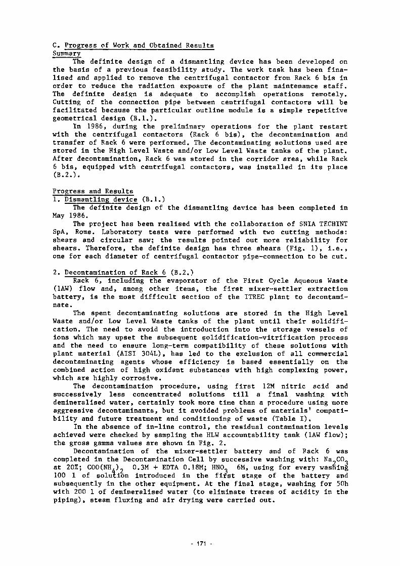
C. Progress of Work and Obtained Results Summary
The definite design of a dismantling device has been developed on the basis of a previous feasibility study. The work task has been finalised and applied to remove the centrifugal contactor from Rack 6 bis in order to reduce the radiation exposure of the plant maintenance staff. The definite design is adequate to accomplish operations remotely. Cutting of the connection pipe between centrifugal contactors will be facilitated because the particular outline module is a simple repetitive geometrical design (B.I.).
In 1986, during the preliminary operations for the plant restart with the centrifugal contactors (Rack 6 bis), the decontamination and transfer of Rack 6 were performed. The decontaminating solutions used are stored in the High Level Waste and/or Low Level Waste tanks of the plant. After decontamination, Rack 6 was stored in the corridor area, while Rack 6 bis, equipped with centrifugal contactors, was installed in its place (B.2.).
Progress and Results 1. Dismantling device (B.l.)
The definite design of the dismantling device has been completed in May 1986.
The project has been realised with the collaboration of SNIA TECHINT SpA, Rome. Laboratory tests were performed with two cutting methods: shears and circular saw; the results pointed out more reliability for shears. Therefore, the definite design has three shears (Fig. 1), i.e., one for each diameter of centrifugal contactor pipe-connection to be cut.
2. Decontamination of Rack 6 (B.2.) Rack 6, including the evaporator of the First Cycle Aqueous Waste
(1AW) flow and, among other items, the first mixer-settler extraction battery, is the most difficult section of the ITREC plant to decontaminate.
The spent decontaminating solutions are stored in the High Level Waste and/or Low Level Waste tanks of the plant until their solidification. The need to avoid the introduction into the storage vessels of ions which may upset the subsequent solidification-vitrification process and the need to ensure long-term compatibility of these solutions with plant material (AISI 304L), has led to the exclusion of all commercial decontaminating agents whose efficiency is based essentially on the combined action of high oxidant substances with high complexing power, which are highly corrosive.
The decontamination procedure, using first 12M nitric acid and successively less concentrated solutions till a final washing with demineralised water, certainly took more time than a procedure using more aggressive decontaminants, but it avoided problems of materials' compatibility and future treatment and conditioning of waste (Table I).
In the absence of in-line control, the residual contamination levels achieved were checked by sampling the HLW accountability tank (1AW flow); the gross gamma values are shown in Fig. 2.
Decontamination of the mixer-settler battery and of Pack 6 was completed in the Decontamination Cell by successive washing with: Na„CO„ at 20%; C00(NH,)2 0.3M + EDTA 0.18M; HNCL 6M, using for every washing 100 1 of solution introduced in the first stage of the battery and subsequently in the other equipment. At the final stage, washing for 50h with 200 1 of demineralised water (to eliminate traces of acidity in the piping), steam fluxing and air drying were carried out.
171
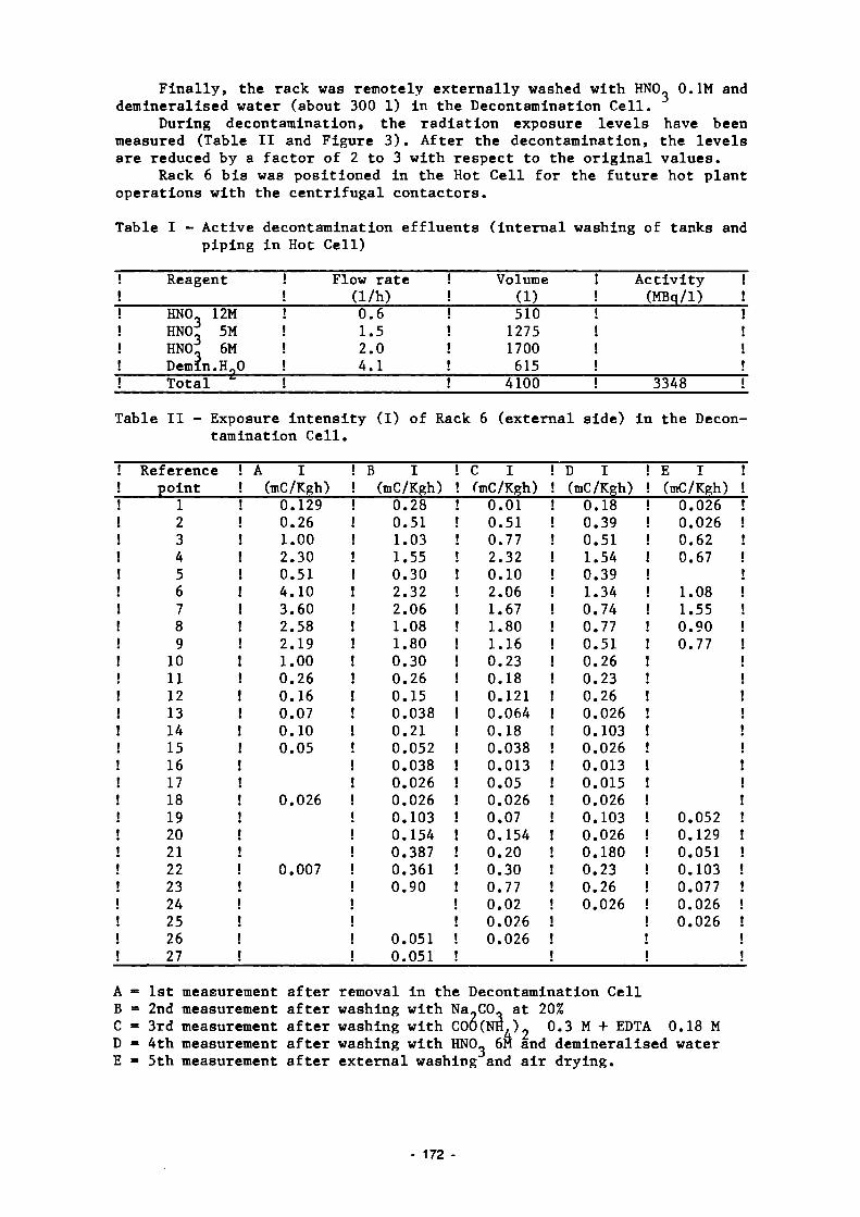
Finally, the rack was remotely externally washed with HNO_ 0.1M and demineralised water (about 300 1) in the Decontamination Cell.
During decontamination, the radiation exposure levels have been measured (Table II and Figure 3). After the decontamination, the levels are reduced by a factor of 2 to 3 with respect to the original values.
Rack 6 bis was positioned in the Hot Cell for the future hot plant operations with the centrifugal contactors.
Table I Active decontamination effluents (internal washing of tanks and piping in Hot Cell)
! Reagent ! Flow rate ! Volume ! ! (1/h) ! (1) ! HNO 12M ! 0.6 ! 510 ! HNO]: 5M ! 1.5 ! 1275 ! HNO;: 6M ! 2.0 ! 1700 ! DemIn.H„0 ! 4.1 ! 615 ! Total *" ! ! 4100
Activity ! (MBq/1) !
3348 !
Table II Exposure intensity (I) of Rack 6 (external side) in the Decontamination Cell.
! Reference ! point ! 1 ! 2 ! 3 ! 4 ! 5 ! 6 ! 7 ! 8 ! 9 ! 10 ! 11 ! 12 ! 13 ! 14 ! 15 ! 16 ! 17 ! 18 ! 19 ! 20 ! 21 ! 22 ! 23 ! 24 ! 25 ! 26 ! 27
! A I ! (mC/Kgh) ! 0.129 ! 0.26 ! 1.00 ! 2.30 ! 0.51 ! 4.10 ! 3.60 ! 2.58 ! 2.19 ! 1.00 ! 0.26 ! 0.16 ! 0.07 ! 0.10 ! 0.05
! 0.026
! 0.007
. B I
. (mC/Kgh) ! 0.28
0.51 1.03 1.55 0.30 2.32 2.06 1.08 1.80 0.30 0.26 0.15 0.038 0.21 0.052 0.038 0.026 0.026 0.103 0.154 0.387 0.361 0.90
0.051 ! 0.051 «
C I ' (mC/Kgh)
0.01 0.51 0.77 2.32 0.10 2.06 1.67 1.80 1.16 0.23 0.18 0.121 0.064 0.18 0.038 0.013 0.05 0.026 0.07 0.154 0.20 0.30 0.77 0.02 0.026 0.026
! D I ! (mC/Kgh) ! 0.18 ! 0.39 ! 0.51 ! 1.54 ! 0.39 ! 1.34 ! 0.74 ! 0.77 ! 0.51 ! 0.26 ! 0.23 ! 0.26 ! 0.026 ! 0.103 ! 0.026 ! 0.013 ! 0.015 ! 0.026 ! 0.103 ! 0.026 ! 0.180 ! 0.23 ! 0.26 ! 0.026
E I ! ! (mC/Kgh) ! ! 0.026 ! ! 0.026 ! ! 0.62 !
0.67 !
! 1.08 ! ! 1.55 !
0.90 ! 0.77 !
0.052 ! 0.129 ! 0.051 ! 0.103 ! 0.077 ! 0.026 ! 0.026 !
A = 1st measurement after removal in the Decontamination Cell B = 2nd measurement after washing with Na_C0, at 20% C = 3rd measurement after washing with C00(NH,)? 0.3 M + EDTA 0.18 M D ■ 4th measurement after washing with HNO 6M and demineralised water E = 5th measurement after external washing and air drying.
172

CENTRIFUGAL CONTACTORS
TV CAMERA
SHEARS /
=? .' -fie ^s^ W ^ri-i--/---T
^ ? > .
rrxr ^ ¿ Æ S T ̂̂ c ii
Figure 1. Pipe cutting device
SHEARS
10 4_MBcj/l
10
10° __
10 __
10
Figure 2. Gross gamma values in 1AW flow during decontamination operation
- 173 -

Figure 3. Rack 6: radiation exposure intensity measuring points.
174

7.2. Testing of Cobalt-free Alloys for Valve Applications Using a Special Test Loop
Contractors: Framatome & Cie, Paris and Commissariat à l'Energie Atomique, CEN Saclay, France
Contract N°: FIlD-0053 Working Period: July 1986 - December 1988 Proiect Leader: C. Benhamou
A. Objectives and Scope The radiation level around the components of Pressurised Water
Reactors (PWR) particularly governs the radiation exposure of the workers during the periodic maintenance operations, as well as during decommissioning operations. Since the activation product cobalt-60 is one of the main contributions to this exposure, the use of cobalt alloys in the primary circuit should be avoided as far as possible.
The alloys likely to replace cobalt allovs mainly used in nuclear cocks and valves, e.g. Stellite Crade 6 and Grade 12, must comply with following criteria:
good weldability; - hardness equivalent to that of cobalt alloys; - resistance to friction and wear equivalent to that of the cobalt
alloys. In the past few years, Framatome, jointly with CEA, assessed a
number of hard cobalt-free alloys considered as promising; two of them were selected: Cenium Z 20 and Colmonov 5. A third alloy will be considered: Everit 50, selected as a result of the first Community research programme f see final report EUR 9865), if information necessary to its realisation is available.
This research aims at establishing the performances of these three alloys, comparatively to Stellite Grade 6, on valves mounted on DOUBLEAU loop of CEA, operated in conditions as close as possible to PWR working conditions. The selected valves are globe-valves and swing check-valves.
The research is led by Framatome.
B. Work Programme B.1. Basic study including design and specifications of the selected
valves (Framatome). Synopsis of results obtained on hard cobalt-free alloys in order to justify the selection of Cenium Z 20 and Colmonoy 5 (Framatome) . Commissioning of the valves with deposits of Cenium Z 20 and Colmonoy 5 and, if possible, Fverit 50, compared with Stellite Grade 6 hard-faced valves (Framatome). Implementation of the selected hard-faced valves in the DOUBLEAU loop and deposits testing (CEA):
B.4.1. Endurance tests under PWR primary circuit conditions (320CC, 160 bars, pH=7, 1500 cycles).
B.4.2. Resistance to thermal shocks tests (100°C and 250°C). B.4.3. Erosion tests at 70°C and 320°C during 10 minutes. P.5. Observation of valves behaviour during tests and examination of
deposits and parts (dye-penetrant testing, internal tightness, surface state) after each series of tests (CEA).
B.6. Conclusions and recommendations for using hard cobalt-free alloys as deposit in the valves (Framatome).
B.
B.
B.
, 2 .
. 3 .
. 4 .
- 175

C. Progress of Work and Obtained Results Summary
The procurement requirements of valves to be tested or "DOUBLEAU" loop of CEA have been discussed with valve suppliers; this Included the selection of cobalt-free alloys for hard-facing deposits and integral products to replaced cobalt-based materials in current use In nuclear plants (R.3.).
Progress and Results SEREG and VELAN-RATEAU were selected as valve manufacturers. The
valves and the alloys selected for more extensive study in the actual progamme are as follows (Figures 1, ? and 3):
- Three globe-valves (2 inches)
Globe valve
1*
2
J
Welding process
Oxyace-tylene flame TIG
TIG
Hard-facing deposit on body seat Stellite grade 6
Colmonoy 4
Cenium 36
Hard-facing deposit on plug Stellite grade 12
Colmonoy 5
Cenium Z 20
Integral ring
Virium 16 Centrifugally
cast Nitronic 60
forged Cenium Z 20
Centrifugally cast
- Three valve bodies (2 inches) with bonnet
Valve body with bonnet
1* 2 3
V/elding process
Oxyacetylene flame TIG TIG
Hard-facing deposit on body seat
Stellite grade 6 Cenium 36 Everit 50
- Three swing check-valves (3 inches)
Check valve
1*
2
3
Welding process
Plasma
Plasma
TIG
Hard-facing deposit on body seat Stellite grade 6
Cenium Z 20
Colmonoy 4-26
Hard-facing deposit on plug Stellite grade 6
Cenium Z 20
Colmonoy 4-26
Integral ring
Stellite grade 6 forged
Nitronic 60 forged
Colmonoy 4-26 Centrifugally
cast
The manufacture of these valves is in progress.
*: reference
- 176

R. : Body hardfacing
R : Plug Bearing hardfacing
R : Back Plug hardfacing
13 : In tegra l Ring
FIGURE 1 : GLOBE-VALVE
R : Body hardfacing
FIGURE 2 : BODY OF GLOBE-VALVE WITH BONNET
177 -

S t e l Li t e
10— ţ •i
ih
attTiw A A
3 : Seat with harcWaced bearing face 4 : Disk with hardiaced bearing face IO : Integral Ring
FIGURE 3 : SWING CHECK-VALVE
178 -

7.3. In-situ Sealing of Concrete Surface by Organic Impregnation and Polymerisation
Contractor: Snia Techint Spa, Roma, Italy Contract N°: FI1D-0055 Working Period: October 1986 - December 1988 Project Leader: V. Pellecchia
A. Objectives and Scope The impregnation by resins of concrete structure is a process known
as PIC (Polymer Impregnated Concrete). This process consists of dehydration of concrete, injection of monomer and thermopolymerisation of the resin. The PIC process is utilised to improve the chemical and physical behaviour of concrete structures, in order to extend the lifetime of bridges and viaducts under heavy traffic and severe atmospheric conditions. In the nuclear field the PIC process is being developed for immobilisation of radioactive wastes.
The objective of this research is to optimise the PIC technique for horizontal, vertical and subvertical concrete surfaces.
In a nuclear facility the impregnation of concrete structure is expected to give the following advantages: - increase of mechanical resistance to impact loads, wear and abrasion; - increase of leach resistance;
increase of the mechanical restraints load capability; - no maintenance required during plant operating lifetime; - long-term integrity after final shutdown of the plant; - very low capability to absorb contaminants because of full occlusion
of all porosities of concrete structure. The research is mainly directed to verify the above-mentioned points
by designing, manufacturing and testing prototype equipment. The research programme will be jointly carried out with ITALCEMENTI Spa.
B. Work Programme B.1. Design, manufacturing and implementation of special prototype device
for impregnation by resins of concrete structures. B.2. Pre-operational tests on concrete structures having different
surfaces, in order to verify capability of experimental equipment to perform the injection of the monomer in all directions.
B.3. Optimisation of the PIC process parameters (temperature, vacuum dehydration, monomer pressure injection, etc.)
B.4. Oualification of the PIC process including comparison of the properties of the concrete matrix before and after the PIC treatment (mechanical and chemical tests, porosity measurement, etc.).
179 -

C. Progress of work and obtained results Summary
According to point B.l. of work programme, preliminary tests have been carried out in order to verify the main service requirements for the monomer impregnation equipment. The experimental campaign gave satisfactory results.
Progress and results Prior to the detailed engineering as per point B.l. of work program
me, a supporting experimental programme was carried out in order to verify: - Capability of adequate coupling of the working chambers (as well for
concrete dehydration as for monomer impregnation) to surfaces to be treated, without external restraints but only by means of vacuum action.
- Capability of coupling in all directions, including vertical walls or ceilings.
- Capability of sealing monomer inside impregnation chamber during injection.
- Capability of seals to withstand the chemical attack of monomers (styrene or methylmethacrylate). Different prototypes of working chambers, manufactured in scale 1:4,
were tested. The best results were obtained with the model shown in Fig. 1.
To confine monomer inside the impregnation chamber, different sealents have been tested: silicone mastics and rubber gaskets. The optimisation has been achieved by means of rectangular cross section rubber gasket. The elastomeric matrix was a closed cells type, hardness 20 Shore.
Geometry of working chamber shown in Fig. 1 is daughter of a previous arrangement where vacuum annulus was integrant part of external board of working chamber. Tests carried out with that preliminary geometry gave different troubles: - extreme rigidity of structure and following bad coupling on surfaces
to be treated; - suction of monomer inside vacuum annulus and following loss of tight
ness to liquid. With the last geometry (see Fig. 1), these problems did not arise.
The final setting up of geometry of injection chamber is adequate also for the dehydration chamber.
The general arrangement of PIC impregnation prototype unit is shown in Fig. 2.
180

VACUUM ANNUL US
/MPRE6NAT/0N CHAMBER
HYDRAULIC T///?L/Sr
VACUÜM AtVNUiUS
IT' I ~ V Ò i
Figure 1. The working chamber.
- 181

« •-•—=*.•-» .-"- -
Figure 2. PIC impregnation prototype unit,
182 -

7.4. Influence of Design Features on Decommissioning of a Large Fast Breeder Reactor
Contractor: Novatome, Le Plessis Robinson, France Contract N°: FI1D-0056 Working Period: October 1986 - June 1988 Project Leader: C. Alary
A. Objectives and Scope The objective of this research is the identification of the design
and construction rules which should reasonably be brought into operation for the projected Fast Breeder Reactors (FBRs) in order to facilitate their dismantling.
A pool-type sodium-cooled FBR with a generating power larger than 1000 MWe will be taken as a reference for this study. Priority will be given to design features involving low equipment costs and little developments. Other features will only be mentioned.
B. Work Programme B. 1. Compilation and analysis of the design features of a FBR
(> 1000 MWe) with regard to decommissioning (main dimensions and quantities, nature and localisation of contamination and activation, capacities of auxiliary systems, etc.)
B.2. Identification of the main features determinant to decommissioning: calculation of activation and dose rates of major components, assessment of problems posed by contamination, etc.
B.3. Study of various stages of dismantling, including assessment of remote dismantling and deferred dismantling.
B.4. Identification and evaluation of cost-effective design features facilitating decommissioning, considering low-cobalt steels, coatings, primary circuit draining and rinsing, decontamination of reactor internals, remote dismantling, etc.
C. Progress of Work and Obtained Result's No work was performed in 1986, because of reorganisation responsibi
lities of the Contractor's staff.
183
8. SECTION C: TESTING OF NEW TECHNIQUES UNDER REAL CONDITIONS
In the course of the progressive development of new techniques, ever greater importance will attach to the testing of these techniques under representative conditions, in particular the presence of radioactivity. Industrial decommissioning operations undertaken in Member States would offer valuable opportunities for such testing. Because of the importance of this subject, it has been added to the 1984-88 programme as a separate section.
Twelve research contracts relating to Section C were being executed in 1986, including six new contracts concluded in 1986 as well as one contract whose execution has been completed in 1986.
- 184

8.1. Dismantling and Decontamination of a Feedwater Preheater Tube Bundle of Garigliano BWR
Contractor: Ente Nazionale per l'Energia Elettrica, Roire, Italy Contract N°: FI1D-0023 Working Period: November 1984 - December 1988 Proiect Leader: A. Bertini
A. Objectives and Scope The decontamination for decommissioning purposes has not yet been
applied extensively for the total cleaning of large components. In the frame of heat-exchanger decontamination, only soft chemicals
have been applied on large scale, and unrestricted release levels have never been obtained. Many problems are connected with tube bundles which have very large surfaces and which are contaminated both inside and outside.
The scope of the present work is to demonstrate the feasibility of dismantling and decontamination of a large component coming from a first generation BWR (Garigliano). Experience gained in other plants will be taken into account, in the sense that the decontamination of the shell, and probably of the tube-sheet, may be carried out by electrochemical way. This study will be mainly focused on the decontamination of tube bundles.
Moreover, the estimation of the amount and the composition of secondary wastes produced is an aim of the work. Finally, the importance of decontamination techniques in decommissioning and, in particular, for the unrestricted release of turbine house building parts, of systems and components, will be evaluated.
The study will result in the assessment and qualification of an effective and economic technique for the decontamination of large and complex components with a production of secondary wastes in limited quantities.
B. Work Programme B.1. Preliminary evaluation of the characteristics of the selected
feedheater, including operating data, with respect to water chemistry and radioactivity inventory.
B.2. Determination of the radioactivity inventory of the feedheater including measurements on scrap samples.
B.3. Laboratory investigations on the ultrasonic and chemical procedures on representative samples, including tests on an appropriate treatment of the spent decontaminant.
B.4. Definition and selection of the most suitable procedure for the determination of the residual activity inventory.
B.5. Design and construction of an appropriate decontamination facility. B.6. Dismantling and decontamination of the feedheater, treatment of the
spent decontaminant, conditioning of the secondary wastes and determination of the residual activity inventory.
B.7. Evaluation of obtained results and final assessment for potential application to components of full-size BWR plants.
185

C. Progress of work and obtained results
Summary The laboratory tests carried out in the DECO lab on samples taken from the tube bundle of preheater No. 4 of Garigliano BWR are presented. In particular the results of tests performed with ultrasounds (20-40 Hz) in connection with aggressive chemicals (HCl, HF + HNO ), at 40-80°C, on 3 cm and 40 cm tube specimens are described in detail. The first full scale test performed at Garigliano plant with an assembly of 20 tubes is also discussed. The preliminary results show that DFs about 30 and final radioactivity levels about 2 Bq/cm were reached even though the process was not optimizedCDF = Decontamination Factor). The procedure for measuring final residual radioactivity on the tubes is discussed with reference to tests with direct gamma spectrometry by a large Na-I detector on 40 cm long tubes.
Progress and results 1. Laboratory investigations on the ultrasonic and chemical procedure on
representative samples, including tests on an appropriate treatment of spent decontaminant (B.3) Laboratory testing More than 10 tests on 3 cm long specimens were carried out in order to
check on real materials the conditions tested in the preliminary experiments on non-active and some radioactive specimens.
The tests considered the following conditions: - 2 temperatures : 40 (low) and 70 (80) °C (high); - 2 aggressive solutions: HCl and HF/HN0 ; - presence or absence of ultrasounds; - reference tests in demineralized water; - tests after outside surface was fully clean (contamination only inside the tube specimen).
All the experiments were performed using 0.5 1 of chemical solution in a 1 litre teflon beaker.
Some results are given in Figures 1 and 2. The following conclusions can be drawn:
- the synergic effect between ultrasound & chemicals, reported and discussed last year, was found clearly only in the tests with HF/HN0 solution and it is more obvious at low temperature;
- the data of the tests with HCl solution appear to be dispersed and more difficult to explain. At low temperature decontamination was not possible without the ultrasounds but the weight losses are higher than in the test with water.
During these tests, information on the contaminated oxide was acquired. It appeared to be composed of two separate layers: the first dishomogeneous and inconsistent, is easy to remove (ultrasound in water can remove it) and it retains about 80-90% of the radioactivity; the second is more compact, tenacious and difficult to remove. Figure 3 shows the Co-60 and Cs-137 radioactivities as a function of the thickness removed.
186

At the end of the tests the tube treated with HF/HNO solution appears to be clean and shiny, while the tube treated with HCl solution appears to be still covered with the oxide.
A test was carried out on six specimens, about 10 cm long, loaded in bulk, using HF/HNO solution. The results show tube specimens with a different behaviour. Looking at the specimens, some are clean and shiny, others are still black and oxidized on the entire surface and others are partly covered with oxide.
At the end of this series of tests, it was decided to use the solution HF/HNO with ultrasounds at low temperature for the next tests (even though other conditions were shown to be effective). On making this choice it is always possible to improve the decontamination effectiveness by increasing the temperature (from low to high) and/or the concentration of chemicals.
Preliminary full scale test After the laboratory testing, a preliminary test on an assembly of 20
vubes about 40 cm long was performed, in the hot chemical laboratory of the BWR Garigliano power station using a specially designed rig.
The test was performed in the following conditions: volume of solution total exposed surface chemical solution
27.5 litres; 72.81 dm ; 3% vol. HF + 10% vol. HNO for 5.5 h and 5% vol.
3 HF + 10% HNO for 1 more hour.
3 The test started at room temperature; nevertheless because of the ef
fects of ultrasound and pump, the temperature increased to 40-45°C in 3 h. The decision to add some more 2% volume HF was taken during the test
when a visual check of the assembly showed that some tubes were not clean after 5.5 h of test time.
Looking at the tube assembly after the test, some tubes appeared to be still partially dark, covered with a black oxide, on the external surface.
A preliminary analysis of these results shows that: - the tube assembly is partially contaminated. The gross DF is about 120 as
arithmetic average and about 30 as harmonic average; - only some tubes of the assembly appear to be totally cleaned: the posi
tion in the tank seems to have some effect; - the increase of the solution aggressiveness by adding more HF did not
appear to have any appreciable effect. At the end of the test, the spent decontaminant solution was neutral
ized up to pH 8 by adding about 4.5 kg of NaOH. The residual sludges recovered on the conical bottom of the tank were discharged after separation from the floating solution. The volume of the sludges was about 3 1 with a radioactivity of about 4*10 Bq/1 (about 100% Co-60), while the volume of
2 the floating solution was 35 1 with a radioactivity of 4*10 Bq/1 (85% Co-60 and 15% Cs-137). 2. Definition and selection of the most suitable procedure for the deter
mination of the residual activity inventory (B.2) Direct gamma spectrometry was selected as base technique for measuring
187 -

the residual radioactivity on the decontaminated tubes. Gamma counts were performed on each test specimen at the end of the
test and compared with the measurement before testing. Usually the measurements were carried out by Na-I detectors and referred to Co-60.
In order to validate these measurements specific gamma spectrometries were performed.
The measurements on 40 cm long tubes were performed using a large cylindrical (5"x4") Na-I detector connected with a multichannel analyzer. It was located in a shielded box commonly used for Whole Body Counter measurements and it has a very low background level (2.5 flR/h).
To optimize the system, several measurement geometries were checked. The selected geometry considers the tubes located vertically around the detector at a distance of 5 cm (Fig. 4). This geometry has the highest sensitivity and it is axysimmetric allowing to measure from 1 to 24 tubes with the same calibration.
The system was calibrated using a standard 60-Co source to mark the inside surface of tubes similar to the tubes to be measured both for dimension and material.
As a preliminary conclusion, this system configuration allows us to measure the residual radioactivity on a number of 40 cm long tubes from 1 to 24 in a few minutes (5-10 min) with a detection limit much Lower than 1 Bq/cm (in the worst case of a single tube the detection limit is about 0.1 Bq/cm and 0.1 Bq/g).
A residual radioactivity less than 2 Bq/cm was estimated on the tubes used in the preliminary full scale test. The average arithmetical of the radioactivity removed and the weight losses for each tube, are given in Figs. 5 and 6, respectively.
- 188

o H 2 0 , 7 0 ° C . ULT. • HF/HNO3, 70°C. * HF/HNO , 70°C.ULT
1 \
\ \ '\ \ \ V
v ' * 1
1
- ' " ti 1 ¿ta•
*
ground l e v e l
0 100 200 t ime(min
10
10
t ime(min)
Figure 1 - Co-60 radioactivity versus test Figure 2 - Co-60 radioactivity versus test tine during a test with ultrasounds tine during a test with ultrasounds and HF/HNO chemicals at i»0°C. and HF/HNO chemicals at 70°C.
10
^ 1
•210
-2 10 L
»
*
-
1
*
- \ C s - 1 3 7
'
1
\Co-60
,
\
• ̂ __
\
1
-
^ » .
0 1 10 100 removed thichness (n«i)
Figure 3 - Co-60 and Cs-137 residual radioactivity as a function of thickness removed.
Figure 4 - Configuration of the system for measuring final radioactivity on <«0 cm long tube specimens.
189

Á y~l
ZL
i=_2_Z2l ¡!! 7 7
é&\
/ r X
4 z 2p
*5 ?: Q
/ • /
T
/
Figure 5 - Removed radioactivity (%) on the tubes used in the full scale test (numbers indicate the test tubes).
.c -o
Figure 6 - Weight losses on the tubesused in the full scale test (numbers indicate the test tubes).
190
8.2. Conditioning, Transport and Dismantling of Very Large Plutonium Glove Boxes
Contractor: Belgonucléaire, Dessel, Belgium Contract N°: FI1D-0024 Working Period: July 1984 - June 1986 Project Leader: J. Draulans
A. Objectives and Scope The decommissioning of standard-sized plutonium glove boxes has been
performed in several countries for several years. However, the dismantling of very large alpha-radiating units has yet to be demonstrated.
Plutonium research laboratories and mixed-oxide fuel fabrication plants have to be partially dismantled in the near future. During these dismantling tasks, severe problems will arise with the decommissioning of huge glove boxes containing very large and heavy equipment. These units have to be conditioned and transported to an ad-hoc installation for dismantling and fina] disposal. The techniques used until now for the conditioning and the transport of small units are not applicable in this field. Indeed, new techniques have to be developed for assuring at any time the leak-tightness of such units up to the moment of their dismantling.
The aim of the research is to develop concepts needed and to execute and demonstrate decommissioning operations on five large glove boxes of the Dessel mixed-oxide fuel fabrication plant. These operations include conditioning, transportation on public roads to an external dismantling cell, dismantling and assessment of applied techniques.
B. Work Programme B.1. Conditioning for allowing safe transportation of five large pluto
nium glove boxes, formerly used for mixed-oxide fuel fabrication. B.2. Preparation and safe and leak-tight transportation of five large
glove boxes to a special dismantling installation. B.3. Adaptation for air-tight introduction of the glove boxes into the
dismantling cell, execution of the dismantling by a selected appropriate procedure and final assessment of the applied techniques with recommendations for further applications.
191

C. Progress of work and obtained results Summary :
In 1985 the 5 large glove boxes, making part of this contract, have been decommissioned and removed from the BELGONUCLEAIRE hOX plant, 2 have been transferred directly to the SCK-CEN dismantling plant and are dismantled, 3 have been transported to a temporary storage area.
These 3 have been transported in 1986 to the SCK/CEN dismantling plant and 2 have been dismantled whilst the 3° has been introduced in the entrance lock of the dismantling area at the end of the year.
The major problems encountered during the dismantling of the glove boxes were the strong increase of the plutonium concentration in the air of the dismantling room and the need for adequate equipment for the dismantling operations. Progress and Results : 1. The transportation of the glove boxes (B.2)
No major problems have been encountered during tbe truck loading and unloading operations and the transportation of the 3 glove boxes from the temporary storage area to the SCK/CEN dismantling plant. 2. Adaptation for air tight introduction of the glove boxes into the dis-dismantling cell, execution of the dismantling by a selected appropriate procedure and final assessment of the applied techniques with recommendations for further applications. (B.3.) - Glove _box AOl^ : The total height of 3,4m did not permit a direct intro
duction of the glove box into the entrance lock of the dismantling room, but it was possible after removing the upper part. This part was UO2 contaminated and suspected to be contaminated with traces of Pu.
This operation was performed under plastic tent and with operators in frogmen suit« No contamination, worthy to be mentionned, has been found out of the glove box. A total of 446 hours effective operator-working time was required for this operation. Dismantling of the glove box.
The glove box has been dismantled following the procedures defined for the former dismantled ones. During the former dismantling tasks an increase of the contamination risk of the gaskets on the frogmen suits has been stated as soon as the air contamination level reached 10 - 0
uCi/cmJ. In order to reduce this risk the Health Physics department imposed to stop the dismantling as soon as this value was attained. Cleaning operations in the alpha room could be performed in order to reduce the air contamination.
Remark : the question arised during the cleaning operations whether it was not better to continue the dismantling operation as fast as possible in order to reduce the number of operator-in frogmen suit hours. Further information is given in table 1 "Decom. of glove box A01".
The task has been performed in 31 workdays by the normal crew. A total of 1374h have been required to finish the task except the demolishing of the window pannels.
A total of 25 final disposal waste drums, each of 200 1, (demolished window pannels included) are required; the total weight is about 8650 kg.
- Glove box All^ : The glove box has been dismantled following the procedures defined for the former dismantled ones. The task
has been performed in 15 workdays by the normal 5 persons crew.
192 -

A total of 450 hours have been required to finish the task, except the treatment of the 20mm thick bottom-plate. This bottom-plate treatment resulted in 2 final disposal drums. In total 19 200 1 final disposal waste drums have been used with a total end weight of 6431 kg.
During the task a considerable increase of the air contamination has been stated in both the frogmen area and in the insolubilization room. The following incidents have been registered : - contaminations have been found on the gaskets of the frogmen suits,
without any contamination of the operator(s); - 2 x urgent replacement of the gloves in a frogmen suit (without any con
tamination of the operator). Further information is given in table 2 "Decora, of glove box All"
3. Conclusions, advices, attempt to limit definition - Conclusions
The complete task has been performed nearly within the original scheduled timeperiod and within the original cost estimation. The decommissioning operations in the BELGONUCLEAIRE MOFF plant, the glove box transportation over private and public roads and the final dismantling have been performed without any major incident.
A considerable gain of time was achieved by choosing the solution of evacuation the entire glove boxes to a specialized institute for destruction. Considerable dose reduction for the decommissioning operators could be achlved by taking into account the advise hereafter. - Advice
- The glove boxes in service should thoroughly be cleaned at regular intervals.
- All openings and grooves were dust can accumulate or can settle down should be closed by means of a not liardening putty.
- All the powder treatment equipment inside the glove boxes should be connected to a general dust collecting vacuum cleaning system; air inlets should be provided around all points which have to be coupled and disconnected.
- The equipment inside the glove boxes should if possible be designed for dismounting inside the glove boxes so that the latter only have easy to handle reduced dimensions.
- From each glove box in service a complete file, including drawings, equipment documentation and necessary descriptions etc. should be kept and adjusted as modifications are effectuated on the glove box or its content. ~ Attempt to define a lower limit below which the glove boxes have not
to be cleaned Taken into account that all these values only are collected on the
cleaning operation of 5 glove boxes and therefore have to be treated with care one could conclude that glove boxes, contaminated as the ones described in" this report and having an average glove box dose rate of 25 m Rem/h or cleaned up to this value may be decommissioned without any further effort to reduce this dose rate as far as only dosimetric aspects are considered. However a further cleaning can be required due to other limitations as there are environmental ones, safeguards aspects etc.
193

TABLE 1 : DECOttllSSIONING OF GLOVE BOX A-Ol GROUPED DATA
CO
DATA CONCERNING
THE CLOVE BOX
Data at the start of the dismantling operation
Glove box disconnecting operation Glove box cleaning" operation
Glove| displac, prep. box | + displac. de- I mounting of cam-1 frames nri.s-1 lifting + slon- rotation
ing | packing
DIMENSIONS IN m
3,2 x 1,0 x (2,0 + 2,9)
Quantity ot Pu present
in g Pu
(Quantity of Pu present a t the end of the ope-ration in g Pu
GLOVE BOX VOLUME
i n m 3
6 + 1
account : 22,9 measured: n .a .
1 9 4 -
EFFECTTVE VOLUMES
i n m3
WIKDCW SURF. I NUMBER IN M2 | OF
| GLOVES
17,9 62
Gamma dose rates-con t. in mR/h
window in side a|side b TT "W T
1 10,5 | 3 7 -I I
side c|side d|average 32 | 180 | "gg"
23,- 28,- | 24,6 I I
Glove box dismantling destruction and conditions" TOTALS I
NUMBER OF
OPERATORS
INVOLVED
n . a .
55
n«a.
n . a .
n . a .
n . a . "5
QUIRED WORK
ING TIME
IN HOURS
342
297
295
91
TOTAL GAMMA DOSE PEN-D O S I -hETER
mR
175
2103,-
n-a.
n .a .
n-a .
n .a .
"HIGHEST DOSE
OPERATOR DAY
P E N -DOSIl-ETERI
mR
90
130
n-a.
n-a.
n-a
TOTAL GAMMA DOSE
FLNGER-BADCE I N
mR
n.a .
17991
n-a.
"HIGHEST GAMMA
DOSE OPERATOR
FINGER BADGE
mR
n.a .
1099
n-a.
n .a .
• i n .a . i
AV. GAMMA BODYDOSE
AS RECEIV. BY 4 MAIN OPER.IN mR
87,6
3Bc
190
108
AV GAM-MA FINGE RDOSE AS REC.
BY 4 MAIN OP. IN mR
254
**
- 3 E 3 T
332
70
NUMBER | OF
GLOVES | RE
PLACED I
37
QUANTITY OF Pu REÜVED IN g Pu
During glove box cleaning operations
During glove box deccmissioning operation During glove box dismantling operation TOTALS
dry recoverd
459
" W
fran dried cloths
43
~4T
in vaste
151,9
13,8
163X
t o t a l
653,9
13,8
"S67X
Ratio Effect. Vol. G.B. Volume
Weight Corai. Fin. Disp. drums n
Weight of G.B. + s t i f . frane
_ _. Vol. Fin. Disp. dnms 5,26 . -,, Ratio c » —'-— = 0,75 Vol. of glove box 7
. Vol. Fin. Disp. Drums Effective volume
QUANTITY OF ALPHA 03NTAMINATED WASTE
in 28 1 | in 200 1 drums I drums in 1
ÏT-oT _ ~ ^ Jf Of d r u m s ^ t o t a l | d r u m ş ^ t o t a l
vol . Vs^ vol.
I - ^ 5 0 0 0
* Effective volume : real volume of equipment and structural components "
total in 1
932
252
WEIGHT IN Kg OF CDND. WASTE
8650
QUANTITY OF SUSPECT WASTE IN 1
27 756
27 756
n.a. : not available only putting down on the floor

TABLE 2 : DECOMHSSIONDJG OF CLOVE BCK All GROUPED DATA
yi
DATA CONCERNING
THE GLOVE BOX
Daca at Che s t a r t of Che dismantling operación
Glove box disconnect ing operación Glove box cleaning operación
Glovel displac, prep. box I + displac. de I mounting of com1 frames mis| l i f t ing +
s ion | rocacion ing I packing
1 DEPENSIONS LN |CLOVE BOX
m I VOLUME I I N m 3
1,5x1,0x3,5 | I 5,2 I
IQuanClty of Pu | account : I present 181,5
In g Pu Imeasured: In.a.
Quantity of Pu | present a t the | end of the ope| rat ion in g Pu |
85
EFFECTIVE VOLUMES
I N m 3
WINDOW SURF. INm 2
16,2
Ganna dose ratescone. inmR/h
I
NUMBER OF GLOVES
30
window in
side a |s ide bIside c Iside d|average 19,3 I 16,2 I 10,5 I 20,3 | T o Ï T
I I I I I I
6,9 | 8,1 | 7,5 | 9,4 | 8,0 I I I I I I 1 I
r.lnvp hnv rUgmanrHng ripglTiif rinn anH rnnHi firing
TOTALS lng
NUMBER OF
OPER
ATORS INVOLVED
19
na .
na.
na.
RÉQUIRED WORK
DC TTHE
DJ HOURS
132
80
134
651,7
96,3
86
TOTAL GAMMA DOSE PEN
■DOSI
MÏIER mR
260
535,-
n.a . ~430~ 1630 |
HIGHEST DOSE
OPERATOR DAY
FEN
DOSDEIER nR
90
90
na.
na.
n .a .
TOTAL GAMMA DOSE
FLN3ER
BADGE LN mR
2837
"HIGHEST GAMIA
DOSE OPE
RATOR FDCER
BADGE mR
n a .
285
AV. GAMMA BODYDOSE
AS R E ΠI V . BY 4 MAIN 0PER. IN mR
659
116
16
AV.GAM
MA FLN
GERDOSE AS REC.
BY 4 MAD) OP IN mR
102
83
na.
NUMBER| OF
GLOVESI RE
PLACED |
QUANTITY OF Pu REMOVED DJ g Pu QUANTITY CF ALPHA CONTAMINATED WASTE
During glove box cleaning operations
During glove box decanissioning operation During glove box di ■mantling operation TOTALS
dry recoverd
10,5
TÜ¡F
fraa dried cloths
6,1
T X
in waste
64,0
1,3
65,3
to ta l
80,6
1,3
81,9
Ratio Effect. Vol. G.B. Volume
. Weight Cond. Fin. Disp. drums Weight of G.B. + s t i f . frame
„ . Vol. Fin. Disp. drums 3,8 . ,_ Ratio c » —-— = 0,73
Vol. of glove box 5,2
_ . Vol. Fin. Disp. Drums Ratio c
Effective volume
* Effective volume : real volume of equinnpnt and structural components
to ta l in 1
1072
84
3800
4956
WEIGHT Li kg |—ÕTJÃNTrTT CF G0ND. WASTE
OF SUSPECT I WASTE DJ 1
i n 28 1 I drums \lT~ot | druos^ to ta l
vol in 11
I
1%
6431
6431
n.a. : noe available only putting down on the floor

8.3. Large-Scale Application of Segmenting and Decontamination Techniques
Contractor; Kernkraftwerk RWE-Bayernwerk GmbH, Gundremmingen, Germany
Contract N": FI1D-0025 Working Period; January 1985 - December 1988 Project Leader; W. Stang
A. Objectives and Scope As one of the first nuclear power plants of Germany, Gundremmingen
Unit A operated from 1966 to 1977 until an accident occurred with subse-quential damage to the plant. In 1980, it was decided to decommission the plant. While for the reactor and auxiliary buildings a concept of safe enclosure was issued, some selected systems in the turbine house were dismantled and decontaminated. The aim was to reduce the radioactive waste volume as much as possible and to reclaim usable materials.
This research work is aimed at the development and optimisation of dismantling and decontamination techniques, as well as measurement methods for residual activity, appropriate for a large-scale application (300 Mg) . Economics and health-physic, considerations are main criteria in this research.
B. Work Programme B.1. Selection and large-scale application of techniques for the
cutting of components from the turbine house. B.l.l. Classification of components for dismantling. B.1.2. Laboratory tests of various cutting techniques with subsequent
selection for the most appropriate application. B.1.3. Large-scale application of selected cutting techniques on various
components. B.2. Selection and large-scale application of techniques for the decon
tamination of components from the turbine house. B.2.1. Classification of components for decontamination. B.2.2. Laboratory tests of various decontamination techniques with
subsequent selection for the most appropriate appHcation. B.2.3. Large-scale application of selected decontamination techniques on
various components. B.2.4. Reassessment of existing procedures to facilitate unrestricted
release, based on melting of metallic scrap. B.3. Detailed studies on electrochemical decontamination. B.3.1. Control and optimised use of electrolytes. B.3.2. Development of continuous regeneration procedures for electro
lytes. B.3.3. Development of continuous regeneration procedures for acids. B.3.4. Investigations for optimal conditioning of secondary waste arising
from electrolytes and acids. B.4. Optimisation of methods for the determination of the residual
activity. B.4.1. Classification of components for residual activity measurements. B.4.2. Testing of various measuring techniques with subsequent selection. B.4.3. Large-scale application of selected methods for residual activity
measurements on various components.
196

C. Progress of work nnd obtained resultş
Summary
In the current year 1986 the following large scale applications were carried out by this program:
dismantling of several pipes and armatures dismantling of the lowpressure turbine decontamination of waste oil regeneration of exhausted electrolytes surveying of several plant parts such as steel scrap, electromotors and insulation material.
The following small scale investigations were realized: decontamination by highpressure water introduction of a route card system for documentation.
The decontamination of the condenser tubes will be carried out in 1987. For the simplification of the documentation a route card system was introduced for the acquisition of data of treated parts. In the route card all important data from the dismantling until to an unrestricted release were registered and afterwards computerized. The processed data enable the planning personnel to recall informations about the status of the decommissioning activities referring to mass and activity transfer, effort of time and personnel, as well as the evaluation of the economics of single works.
Progress and results
1. Selection and large scale application of techniques for cutting of components from the turbine house (B.1.)
The dismantling of the lowpressure turbine was started at the end of 1986 with the removal of external housing of the turbine. Afterwards the internal upper part of the housing and the lowpressure rotor will be lifted. In 1985 small scale investigations in cutting techniques were carried out with the result to apply sawing whenever possible. Deviating from this recommendation it was suggested to use torch cutting with local ventilation in special cutting tenta, if plant parts with complicated geometries and low contamination had to be segmented. Therefore torch cutting will probably be chosen for the segmentation of turbine parts in future.
2. Selection and large scale application of techniques for decontamination of components from the turbine house (B.2.)
It was investigated if highpressure water cleaning is a qualified decontamination procedure for large scale applications. Starting from the experiences with the already applicated 70 bars facilities a test series with a rented high pressure aggregate up to 800 bars was initiated. The initial tests were carried out with different pressure stages at previously steam and waterattacked plant parts by the service personnel using hand pistols.
197

In a further test aeries decontamination of condenser tubes was also investigated. Hereby the brass tubes were pushed axially through a splash ring which directed the high-pressure water jet with 3 nozzles to the contaminated surface. The results of the decontamination are listed in table I. During the tests it turned out that the strong adhesive layers in the case of steam-attacked plant parts and of the condenser tubes could not be removed even by a pressure of 800 bars. Only the slightly adhering layers were carried off. By pressure of more than 500 bars the coatings of previously water-attacked parts could be partially removed. After treating with a high-pressure water jet the samples were decontaminated electrochemically in order to obtain a statement if high-pressure water cleaning will result in a reduction of an essential shortening of decontamination time in comparison with not pre-treated parts. The tables II and III show that high-pressure water cleaning prior to electropolishing or pickling causes no significant reduction of decontamination time. The high-pressure water cleaning up to 800 bars for pretreatment is only recommendable if the plant parts have slightly adhering layers and thick coatings. These investigations confirmed that the high-pressure water cleaning up to 800 bars is qualified only restrictedly for large scale decontamination. Generally the economical installations up to 70 bars are sufficient for decommissioning tasks.
During the decommissioning of KRB A a large quantity of lubricating oils had to be decontaminated for unrestricted release. These oils have been drained mainly from the turbine oil tank, the feedwater pumps, the circulation pumps, the booster pumps, and from the control rod drive pumps. Only 15m of 61 m had to be decontaminated as the activity of the majority was under the limit of unrestricted release. The contamination consisted of cobalt 60 and cesium 137 fixed to metal oxide particles suspended in the oils. By extracting the oils with diluted sulfuric acid the acitivity was concentrated in the aqueous phase. As the oils were still containing small quantities of diluted acid, sodium carbonate was added to the oils in order to neutralize traces of acid. This procedure turned the oils clear and the acitivities .far below the limit of unrestricted release. The used diluted sulfuric acid as well as the sodium carbonate could be usod several time3 before they had to be replaced.
3. Detailed studies on electrochemical decontamination (B.3«)
Electrochemical decontamination causes a steady increase of the concentration of dissolved iron in the electrolyte, which therefore has to be regenerated periodically. To attain favourable starting conditions for regeneration, combining of electrochemical decontamination with a chemical decontamination procedure was necessary to increase the percentage of bivalent iron. When a high portion of bivalent iron was obtained, the electrolyte was mixed with an aqueous solution of oxalic acid. By this procedufe the majority of the iron was precipitated as iron oxalate. The activity was mostly separated from the solution by precipitation as well.
198

The iron oxalate was washed with water, dried and stored for subsequent processing. It will be converted into iron oxide by pyrolytic decomposition before final storage. To achieve the initial concentration the diluted phosphoric acid had to be evaporated. This was executed by an oil-heated evaporator. The entire distilled water from this process was stored and reused (see Pig. 2). Since the regeneration of electrolytes began, about 500 tons of metal scrap have been decontaminated. 18 tons of iron oxalate were produced and will be converted,,to 8 tons of iron oxide by pyrolytic decomposition. Altogether 20 m of phosphoric acid with a concentration of 20 - 40 % (by weight) take part in the cycle of decontamination and regeneration. Until now about 70 m of phosphoric acid have been regenerated.
4. Survey methods for determination of the residual activity (B.4.)
In 1986 several surveying procedures for unrestricted release of plant parts were used. The following procedures were of great significance: - oc, ß-surveying by large area counters Especially with digital signal preparation a significant reduction of the measurement time was reached. Normally 5 seconds for one measurement position were sufficient to attain the required accuracy, for unrestricted release. Large area counters (200 cm ) were used for surveying plant parts with definable and measurable surfaces such like plates, pipes, etc.
- a, Q-surveying by probes with special geometry This measurement instruments were applicated to plant parts with holes, corners and edges. Because of their smaller detection area the necessary time for each position amounts to about 20 seconds. This surveying procedure is supported by a digital signal processor.
- /-surveying by liquid-scintillator-colümns This procedure is used for surveying without defined surface e.g. insulation material which is fitted into plastic bags. Especially for this purpose a measurement facility for insulation material has been installed (Fig. 3).
The large scale application of these surveying procedures resulted in a release of
about 1100 tons steel 3crap - about 50 tons of electromotors
about 40 tons insulation material about 410 tons concrete shieldings.
199

Table I
Highpressure water cleaning of contaminated plant parts
10 o o
Sample
D1 D2 B5 D4 D5 D6 W1 Ï2 V3 V4 W5 W6 W7 W3 W9 W10 KR1 KR2 KR3 KR4 KR5 KR6 KR7 KR8 KR9 KR10
Pressure
(bar)
200 bar 400 bar 500 bar 600 bar 800 bar 800 bar 200 bar 300 bar 400 bar 400 bar 500 bar 500 bar 600 bar 600 bar 800 bar 800 bar 200 bar 300 bar 400 bar 500 bar 600 bar 620 bar 750 bar 750 bar 800 bar 800 bar
K,
(Bq/cm2)
22,04 15,03 5,74 7,83 7,57 28,00 0,54 0,80 0,98 0,30 0,72 2,28 1,23 1,45 1,92 1,63 1,71 0,97 10,45 3,00 1,73 2,50 0,81 6,10 1,08 0,83
K2
(Bi/cm2)
4,63 12,79 1,19 3,16 6,15 10,79 0,31 0,46 0,75 0,18 0,32 0,80 0,24 0,27 0,77 0,36 1,09 0,21 0,66 0,37 0,69 1,35 0,24 3,27 0,16 0,42
tr
(1)
4,70 1,17 4,82 2,48 1.23 2,65 1,74 1.74 1,31 1,67 2,25 2,81 5,13 5,37 2,49 4,53 1,57 4,62 15,83 8,11 2.51 1,85 3,38 1,87 6,75 1,97
2
EF
V
KR
contamination before treatment
contamination after treatment
decontamination factor
secondary steamattacked samples
waterattacked samples
condenser tubes
Table II
Treatment time for electrochemical decontamination after highpressure water cleaning
Sample
D2 D5
W3 W6
KR5 KÔ10
K3
(Bq/cm2)
12,79 6,15
0,75 0,80
0,69 0,42
T
(min)
170 160
90 90
5 5
Table III
Treatment time for electrochemical decontamination without any pretreatment Sample
D7 D3
«11 ¥12
KR12 ÌCH13
K1
(Bq/cm2)
8,76 19,27
1,42 0,89
2,79 4,28
T
(min)
180 160
110 100
5 5
T - treatment time K, - contamination after high-pressure water
cleaning K. » contamination before electrochemical
treatment D ■ secondary steam-attacked samples V ■ water-attacked samples KR - condenser tubes

. • . - activity REGENERATED PHOSPHORIC ACID
O
contaminated waste oil
Stirring
Separation oil/acid
DF - 10
decontaminated waste oil
t Sedimentation DF - 20
t Stirring • • •
f Neutralization • t
predecontaminated waste oil with traces of acid
Na2C03
CHEMICAL DECONTAMINATION
50'C 20 - 1.0 V .
OXALIC A
1 ELECTROCHEMICAL DECONTAMINATION
70"C 1.0 - 70 V .
EXHAUSTED PHOSPHORIC ACIO
PRECIPITATION OF IRON OXALATE
1 SUSPENSION
DILUTEO PHOSPHORIC ACID / IRON OXALATE
»
IRON OXALATE
PYROLYTICAL DISINTEGRATION
1 IRON OXIDE
1 CONDITIONING
FOR FINAL STORAGE
SEDIMENTATION CONDE
1 DILUTED PHOSPHORIC ACID
1 EVAPORATION
1 REGENERATED PHOSPHORIC
1 INTERMEDIATE
STORAGE'
(SATE
ACIO
Fig . 1 Decontamination of waste o i l Pig. 2 Procedure of electrochemical decontamination and regeneration of phosphoric acid

shielding
70
shielding
r?m
f H
T H+30
H-30
■55
:^\
'ñ
012
110
1 30
250
detector
Fig . 3 I n s t a l l a t i o n for detecting the res idual contamination of insula t ion material
202

8.4. Development of Techniques to Dispose of the Windscale AGR Heat Exchangers
Contractor: United Kingdom Atomic Energy Authority, Windscale Nuclear Laboratories, United Kingdom
Contract N": FI1D-0026 Working Period: January 1985 - June 1987 Proiect Leader: J.R. Wakefield
A. Objectives and Scope The objective of this research work is to dismantle two heat exchan
gers of the Windscale Advanced Gas-cooled Reactor. This will demonstrate that such plant can be decontaminated and dismantled for disposal without environmental hazard and without exceeding the prescribed radiation dose limits to operatives. The purpose of decontamination is to enable hands-on methods of dismantling to be used and avoid expensive and time-consuming remote operations. A further objective is to establish the nature of corrosion and contamination within the heat exchanger gas-side in order to provide data for future decommissioning of similar plant. Prior to this work, it was known that the radiation levels on the outside of the heat exchangers exhibited a peculiar distribution, but there was insufficient knowledge of the detail to predict the nature of the contamination. However, by removing a limited number of samples, having regard to the doses incurred by the operatives, it is expected to be able to identify the contaminants and recommend methods of removal. It is intended to select two such methods for use on the two heat exchangers and engineer them to minimise the quantities of liquid reagents and secondary waste to be handled. A complete costing and dose inventory will be maintained as the operations proceed.
Other organisations involved in the fulfilment of this contract are: UKAEA Winfrith (characterisation of contamination and selection of decontamination method), BNFL Sellafield (provision of road and rail transport, waste disposal), other contractors (designing, manufacturing and operation of the decontamination plant).
B. Work Programme B.1. Characterisation of surface corrosion and contamination on extracted
samples of the heat exchangers, and selection of an effective contaminant allowing for an acceptable disposal of the secondary waste.
B.2. Design, manufacture and installation of a decontamination plant. B.3. Decontamination of the heat exchangers and conditioning of the
secondary waste. B.A. Dismantling of the boilers and conditioning of the scrap for final
disposal.
203

C. Progress of Work and Obtained Results
Summary The practicality, from a chemistry point of view, of using a heat
exchanger as a storage vessel for spent reagent has been investigated by Chemistry Division, Atomic Energy Establishment, Winfrith (AEEW). Control and Dynamics Group, Winfrith have also undertaken a study of the process control aspects of acid refluxing, which has been proposed as a second method of heat exchanger decontamination.
Partly due to a reappraisal of the financing programme for WAGR decommissioning, and partly due to the need to install an active pipeline to transfer effluent from the fill-and-drain pocess to the BNF plant, the timescale of the heat exchanger project has been extended. Decontamination will now not commence until 1990-91, whereas the contractual work programme ends on 31 December 1988. A reduced programme for completion by the contract date is being devised, and when this is complete a revised proposal and budget, amending the existing contract, will be submitted for the approval of DG XII Contracts Division.
Progress and Results
1. Assessment of the Problems - Determination of Chemistry (B.l) BNF limitations on the quality and rate of discharge of effluent
generated by heat exchanger decontamination have necessitated the inclusion of a neutralising facility and a holding tank in the plant specification. For reasons of economy it was proposed that the heat exchangers themselves should be used as holding tanks. The practicality of this from a chemistry point of view was investigated by AEEW, who carried out further decontamination trials on WAGR heat exchanger tube samples, with reagent contact times up to 100 hours. Both HCl/citric and HN03/citric reagents were tested. The results are summarised in Tables 1-3. The tests showed that due to the dissolution of more iron, neutralisation would give rise to unacceptably large quantities of ferric hydroxide floe which is known to be extremely difficult to filter out by conventional methods. Hydrogen evolution was also measured to assess the hazard.
The feasibility of using acid refluxing as an alternative method of decontaminating the heat exchangers is being re-examined. In particular the process control problems of applying the technique to the WAGR boilers are being investigated by AEEW, who have prepared a preliminary report. The key to the problem is the ability to control the position of the zone where acid vapour condenses, the means of control being hot water feed through the boiler tubes. A basic steady-state mathematical model has been set up, in which the system is treated as a counter-flow heat exchanger. (See Fig 1). The model has demonstrated that a controllable condensation zone is feasible and that its position can be moved up or down the tube banks by operator action. Fig 2 illustrates how the tube configuration has been modelled, and Fig 3 shows the temperature distribution in the heat transfer system as derived from the model.
2. Design, manufacture and installation of the Decontamination Plant (B.2)
A functional specification for decontaminating one heat exchanger by the fill-and-drain process has been finalised. An engineering design specification for the decontamination and effluent conditioning plant,
204

and for the active liquor pipeline, has been prepared in draft, but this has now been shelved for eventual revision when the problems created by effluent disposal constraints have been resolved.
A proposal has been made for carrying out a limited decontamination experiment on an actual heat exchanger using a recirculatory flushing technique with HNO3/citric reagent. The aim is to ensure that the effluent produced is acceptable for disposal via BNI" s treatment plant and is small enough in quantity to be transported there in a road tanker. An engineering specification is being prepared.
All preparatory work on HEs A and C has been completed, ie lagging, pipework, valves, headers, ladders and platforms have been removed.
TABLE I - Elemental Dissolution Rates
Specimen
Superheater (HCl)
Superheater (HNO3)
Evaporator (HCl)
Economiser
Specimen Area
2
84
50
Reagent Volume cm3
450
300
640 850
570 750
Element
Fe
Cr
Fe
Cr
Fe
Cr
Dissolved metal Mg cm-3
9200
22
9800
120
8200
Release Rate
2 cm-
50 mg
120 Mg
58 mg
720 Mg
11 mg
0.70 ' 1.0 Mg 1 1
Fe ' 7200 9.4 mg
Total from heat Exchanger*
Kg
225
0.54
265
3.2
380
0.05
330
(HN03) Cr 0.40 0.6 Mg 0.02
*After 100 hours
- 205

TABLE II - Iron Concentration of Decontamination Solut ions
Specimen
Superheater (HCl)
Superheater (HNO3)
Evaporator (HCl)
Economiser (HNO3)
Iron concentration in solution ug cm-First Hour
A60
480
600
1700
1-6 Hours
3400
2400
6-24 Hours
24-48 Hours
1300
3400
5200 6800
4800 6600
4200 6600
5800 6400
48-100 Hours
9200
9800
8200
7200
TABLE III-Hydrogen Evolution Rate for Hydrochloric Acid Decontaminat ion
Time Period Hour
0-1
1-6
Number of
Hours Mean Fe
Concentration Mg cm-3
6-24 18
24-48 24
48-100 52
530
2400
Total Fe Dissolved*
kg
4700
6700
8700
85
385
Maximum Total Hydrogen
Released m3
35
155
750 305
1070 435
1400 570
Mean Hydrogen Release Rate
m3 h-1
35
24
8.3
5.4
2.6
^Assuming concentration of iron in outer duct "dead-leg" rises to same level as in central duct
206

Condensation zone
C c
c t
c
\
w
Constant boiling mixture of HCl
Preheated fluid at Tta 108°C
Preheated fluid at 108 °C
Preheated fluid at 108 °C
FIGURE 1 REFLUX PROCESS FOR DECONTAMINATION
207

First Second flow split flow split
Inlet
Outlet
FIGURE 2a THE ECONOMISER TUBE BANK
layer 1 layer 2
layer 18
—* layer 18
top
FIGURE 2b TOPOLOGICAL REPRESENTATION OF ECONOMISER FLOW
181 top
_ length in model.
FIGURE 2c MODEL REPRESENTATION OF THE ECONOMISER
208

ro o co
108.0
- 107.5 .
LU CC ZD h-< CU
107.0 .
0 50 100 150 LENGTH (m)
FIGURE 3 : AXIAL TEMPERATURE PROFILES
8.5. Pilot Decommissioning of a Mixed-oxide Fuel Fabrication Facility
Contractor: British Nuclear Fuel pic, Sellafield, United Kingdom Contract N°: FI1D-0027 Working Period: July 1984 - June 1988 Project Leader: A.P. Colquhoun
A. Objectives and Scope The objectives of the project are to pilot the development of
technology for the decommissioning of facilities used in the fabrication of mixed-oxide fuels. Based on existing experience, the aim is to establish the procedures which are the most cost-effective overall under the specific constraints on the disposal of wastes arising and on the radiation exposure of personnel.
The development programme is integrated within the decommissioning of the Co-precipitation Plant which was used to produce mixed-oxide powder for the fabrication of fast reactor fuel. The Plant is on two floors and occupies a total floor area of some 320 m2 within which are housed 14 glove boxes, 2 furnaces, 5 tanks, a scrubber vessel, ventilation ducting and pipework.
The techniques to be tested are those which meet the specific constraints and for which previous research has indicated the potential for large-scale application. Decontamination, dismantling and packaging of the wastes are the operations involved while the radiation, contamination and ingestion hazards impose restrictions on the methods of working. Tt is towards the most effective overall procedure that the techniques will be concerted.
Included in the aspects of this development are the minimising of the amount of alpha-contaminated waste material, the minimising of the radiation exposure to personnel, the identification of the best means of in-situ decontamination, and the most suitable means of measuring in-situ the alpha contamination. Finally, a comparison of costs and radiation exposure from alternative techniaues in the real application of decommissioning will be made.
B. Work Programme B.1. Detailed planning for most appropriate decontamination and disman
tling, including technical specifications and safety assessments for proposed methods and plant modifications and submissions for company and regulatory approvals.
B.2. Execution of modifications, testing of equipment, rehearsing of proposed procedures on plant simulations, followed by in-situ decontamination.
B.3. Rehearsing of dismantling and packaging procedures on plant simulations, followed by in-situ dismantling and packaging.
210 -

C. PROGRESS OF WORKS AND OBTAINED RESULTS
Summary This report describes the continuation of work in support
of the development aspects of the project to decommission the mixed oxide fuel fabrication facility and also the commencement of practical operations in terms of Post Operational Clean Out (POCO) of part of the facility.
During 1986 the outline planning phase was completed to permit cost estimation of the entire project prior to Company funding approval. Meanwhile deployment of the project team (2 Technical Officers, 1 Supervisor and 6 Process Operators) was completed. This in turn made possible provision of safety documentation (Plant Safety Appraisal and that defining arrangements for plant handover to Decommissioning Group) and operational documentation for POCO of the access area and the wet chemistry section of the plant. (See Fig 2)
On development aspects of the project the specification for Freon decontamination equipment was put to competitive tender and finally awarded to NEI Waste Technologies Ltd of Gateshead (UK) in association with Kraftanlagen AG of Heidelberg (BRD) who are jointly undertaking the feasibility study constituting the first phase of the contract. The specifications for Decommissioning In-Situ Plutonium Inventory Monitors (DISPIM) have been produced in consultation with Radiometric Physics Group of BNFL R&D Department and with Company financial approval for the whole project received late in 1986 all major items of this equipment together with the first tranche of reusable modular containment (RMC) are being ordered. An outline design for the conversion of an existing glove box to house an electrolytic decontamination facility for selected items has been prepared.
Progress and Results
1. Planning and Safety Documentation (Bl) Figure 1 shows the stages of planning design and
decontamination which have been largely covered during 1986. These are not mutually exclusive and for much of the period several stages were proceeding at once or on different parts of the plant. For example much of the clean-out/refurbishment was carried out by Decommissioning Group Staff before the facility was officially taken over, whilst the Specifications of items in the development areas was going on throughout the period.
The current situation is that Plant clean-out, equipment refurbishment and decontamination is complete at the "Wet" end of the process unit but only just starting at the "Dry" end, whilst preparation of the detailed dismantling schedule, detailed design and procurement are all in hand. The interactions shown between these items indicate the need for the dismantling schedule to reflect the detailed design of the process, and vice versa, whilst the clean-out/refurbishment may show that an initially planned dismantling route is no longer practical and thus changes are needed.
211

Post Operational Clean-Out (POCO) and Equipment Refurbishment (B2) Most of the practical work in 1986 has been devoted to: a) Cleaning out of the Access Area in which the facility is
situated. b) Overhaul and reinstatement of drives, supply lines etc so
that equipment could be operated for cleaning out. c) Complete washing-out of the "Wet" process cabinets
constituting the initial stages of the process and which handled nitric acid solutions and wet slurries.
It has been previously reported that the plant has been shut down since the end of 1976 but kept in a surveillance and maintenance status until declared redundant. In spite of this considerable cleaning out of the access area was needed and an even greater number of man hours have been required to reactivate engineering systems etc although all safety related equipment had remained serviceable. Significant hold up of materials was also found in the wet process equipment and cabinets and considerable man hours were expended at this stage also. Man hours, radiation uptake and wastes generated are tabulated in Table 1 and a layout of the plant is shown in Fig 2.
Development Aspects (Bl) With the full project team available considerable effort has
been devoted to the development needs of the project and progress has been made in all four areas identified in the previous APR, viz: -
Solvent Jetting, using Freon Reusable Containment Structures Plutonium Monitoring Electrolytic Decontamination
Freon Development (Bl) During 1986 the specification for solvent jetting
equipment was put out to tender. After detailed study of 10 submissions and further discussions the contract for development of this equipment was awarded to NEI Waste Technologies Ltd, divided into an initial phase to establish feasibility (due for completion January 1987) and a subsequent manufacture and commission phase if justified.
Previously identified problems which were to be resolved in the feasibility phase were those of solvent loss into ventilation systems and recovery of removed particulates. In view of the aim only to remove gross loose materials the Contractor proposed operation at a much lower pressure (10 Bar) than has generally been used previously. The effectiveness at this low pressure had therefore also to be tested.
The work so far has shown adequate particulate removal and recovery (albeit on in-active trials only) and the potential for operation without gross loss of solvent or effects on down stream ventilation plants.
Progress to phase II, constituting detailed design, manufacture, inactive commissioning and preparation of appropriate safety assessment and nuclear safety documentation is therefore anticipated at an early date.
- 212

5 , Reusable Modular Containment (Bl) The concept of reusable rather than disposable contamination
barriers was described in the previous APR. A study of the outline dismantling procedure has permitted assessment of the total number and size of standard panels needed plus the number of special items (eg man-entry, waste posting). Because of the division of the facility between first and ground floor two separate showering facilities will be needed also.
In initial order for one portable shower facility and sufficient panels for the first dismantling operations (which will involve the ball-mill) is now being placed.
6. Plutonium Monitoring (Bl) The initial specification noted in the previous APR has been
refined with the assistance of Radiometric Physics Group, R&DD, BNFL Sellafield, to specify several items - collectively 'Decommissioning In-Situ Plutonium Inventory Monitors' (DISPIM) - which are intended to: a) Locate significant quantities of Plutonium residues within the
plant items being dismantled. b) Estimate the quantity of those residues as accurately as
possible. c) Demonstrate the progress of decontamination work to the
lowest levels possible. The equipment will consist of A basic units: a) Modular Neutron Counters - pairs of 3 He detectors in modules
which can be reconfigured for neutron coincidence counting of large items.
b) Roving Gamma Counter - collimateci sodium iodide detector c) Roving Neutron Counter - small He detector. d) Minature alpha probes for measuring residual contamination
in crevices. All the major components are being ordered.
7. Electrolytic Decontamination (Bl) An existing glove box within the facility, used previously
for acid cleaning of filter segments and other components, has been cleaned out in order to be re-equipped for this purpose. Meanwhile an outline design for the installation has been prepared and a list has been drawn up of candidate items of equipment of suitable dimensions for treatment in this proposed unit.
A detailed procedure for decontaminating and refurbishing the glove box awaits the detailed design and procurement of equipment which in turn is of lower priority than other detailed planning as the operation of the electrolytic cleaning unit will necessarily be at a late stage in the project.
213

TABLE I - Det ai Ls of
PHASE
Clean Out of Access Area
Refurbishment of Equipment
Clean Out of Wet Process Suite
MAN HOURS
225
1950
960
Clean-Out and R
MAN MILLISIEVERT
3.7
57.8
32.3
efurbishment
RECOVERABLE RESIDUES
900g Pu 1400g U
SOLID FOR
STORAGE
1m3
1.4m3 ( 95g
Pu)
WASTES FOR BURIAL
2m3
""
214

Ol
Outline Decontamination^ Dismantling Schedule
Preliminary Safety Appraisal
Detailed Decontamination Schedule
Detailed Dismantling Schedule
Plant Clean Out Refurbishment and Decontamination
J
Plant Handover
/>—~ Detailed Design
Outline Design (for Dismantling)
Cost Estimation
Financial Approval for whole Project
Procurement L
Start of Dismantling
Specification of Equipment for Development Aspects
FIGURE 1 - PLANNING DESIGN AND DECONTAMINATION STAGES

-Gantry Cranes
en
Recovery Cabinet
Pump Cabi
Drier Sample Filter Cabinet
Reduction Furnace Sample Cabinet
Filtrate Cabinet
Filtiate Cabinet Stand
i-Top Half of. Elevator Casing
Piecipitator Cabinet Conveyor Cabi net
Feed Chute Cabinet
FIGURE 2 - COPRECIPITATION PLANT

8.6. Testing of New Techniques in Decommissioning of a Fuel (U, Th) Fabrication Plant
Contractor: Nukem GmbH, Hanau, Germany Contract N°: FI1D-0028 Working Period: July 1985 - December 1988 Project Leader: H.D. Fricke
A. Objectives and Scope This research work is aimed at the assessment of new procedures in
the framework of the decommissioning of a plant for the production of Material Test Reactor (MTR) and Thorium High Temperature Reactor (THTR) fuel elements.
Important issues in this work are the preparation of detailed uranium and thorium contamination distribution maps in walls and floors, the execution of various dismantling and decontamination operations under health physics control, the large-scale treatment of arising primary waste and the minimisation of secondary waste. The work will be concluded with an assessment of gained experience, with possible recommendations for future work on similar facilities.
B. Work Programme B.1. Preparation of a map of the distribution of the contamination within
different parts of the fuel fabrication plant. B.2. Determination, by analyses of representative samples, of the pene
tration depth of uranium and thorium in various parts of the facility.
B.3. Controlled decontamination and dismantling of the internal components and of all auxiliary equipment of the plant.
B.4. Assessment of appropriate conditions for the removal of contamination from the walls of the facility and its implementation after acceptance by the Regulatory Bodies.
B.5. Decontamination of the floors and their removal. B.6. Testing of new decontamination procedures for less accessible parts. B.7. Determination of the residual activity and possible further disman
tling of less accessible parts. B.8. Conditioning and assessment of the residual activity of metal waste
for reuse by melting. B.9. Large-scale decontamination of the demolition rubble based on
existing laboratory-scale methods. B.10 Minimising of the secondary waste from decontaminants. B.ll Testing of a NUKEM procedure for container sealing. B.12 Evaluation of obtained results.
217

C. Progress of work and obtained results Surrmary
The main activities performed in 1986 have been the decomissioning of a pyrohydrolysis plant as an example for plants with complex geometries and hardly removable contamination and the exemplary decommissioning of a technical laboratory which has been used in the past for work with open radioactivity.
The pyrohydrolysis plant has been dismantled. The single parts have been decontaminated with tenside resp. acid containing liquids by using high pressurizing pumps. The feed vessel (4,5 m3) has been treated as one part, the reactor containment has been cut into pieces of 180-1-drum size for further exemplary treatment.
In the technical laboratory the installations have been dismantled totally. For the decontamination of walls and floors the penetration depth of the contamination has been measured and chemical, physical and mechanical methods has been used exemplary to create figures and results like decontamination speed and effectiveness, secondary waste generation and health physics aspects.
Progress and results 1. Decommissioning of plants (B. 3.)
As an example for plants with complex geometries the pyrohydrolysis plant has been dismantled into pieces able to be put into 180-1-drums. For the small parts like glove boxes and plane surfaces, the decontamination with tenside containing liquids (Solution B, see tab. l)„was sufficient to reach the limit for unrestricted use of < 0.37 Bq/cm (ct-activity) and < 3.7 Bq/cnv? P) -aci ti vi ty.
Parts, which could not be dismantled like the feed vessel (see fig. 1) and the reactor containment has been treated as follows:
The reactor containment has been cut into pieces able to be put into 180-1-drums. In the next year, our efforts are concerned for exemplary treatment. The feed vessel has been treated with decontamination liquids (see Tab. 1, solution A-D). For cleaning, the liquids were pumped into the vessel by a high pressurized pump. To reach each part of the complex internal surface, various pipes were used. For cleaning of the screw mixer, the drive was put in function during cleaning. The solutions A-D were used in the alphabetic sequence. To prevent contamination of the environment, the off gas system created a negative pressure resp. an air stream into the vessel during the work. The off gas treatment consisted of a prefilter, a glass fibre deep bed filter and a HEPA filter. During the work no increase of airborne activity was detected. The total volume of used liquids was 200 1 with a total removed activity of 2.2 E 6 Bq, i.e. 1.1 E 4 Bq/1. The contaminated liquids were given to the routine waste water treatment. After each campaign the results were measured at the points 1-4 (fig. 1). The results are summarized in tab. I. At all measuring points the activity limits for unrestricted use have been reached. The decontamination success was directly combined with the complexity of the surface.
2. Exemplary deconrnissioning of a technical laboratory The room chosen for the work was used in the past for the Ammonium-
Uranyl-Carbonate (AUC) conversion. Facilities to be dismantled were pumps, solvent containment, precipitation containment, transport cans, filling
- 218

boxes, heating devices and to some extent pipes. These parts are planned for reuse in the new building of NUKEM which is actually under construction. An intermediate ceiling (height 2,2 m, area 18 m ) was desinstalled for scrap.
Dismantling of plants (B. 3., B. 6.) Because the most facilities will be reused, the decontamination was
performed only to remove loose activity. This has been done by NUKEM's cleaning staff. In a secondary step, the pipes and facilities were flushed with 0.1 M HNO., and water. After this, the facilities were disconnected and open pipes were closed on their entrances at the walls. The total volume of cleaning water was 1.5 m with average activities of 92 Bq/1 ( cL) resp. 105 Bq/1 (ß ). An increase of the air activity was not detected. The facilities were packed into containers, the intermediate ceiling was given to conventional scrap.
Penetration depth of U and Th (B. 2.) The walls and floors were measured to detect fixed contamination.
After this, at selected areas the penetration depth of contamination was measured by successive dry grinding (walls) resp. wet grinding (floors) and activity measurements. The grinding dust resp. slurry was removed by vacuum cleaners. During all operations, the air activity was controlled. The results can be summarized as follows: - At the walls the maximum contamination was measured below the surface colour sheets. ?
- At the walls the activity limit of 0.37 Bq/cm was reached after 3 mm grinding, at floors after 5 - 10 mm
- The activity of the removed materials was 50 - 220 Bq/g - No increase in air activity could be detected.
Concepts for decontamination of walls and floors (B.4., B.5.) Because of the porous structure of wall and floor materials chemical
methods like flushing were not considered to be successful. As physical methods like heat or deep temperature only the heat treatment of organic colour layers is technical state. The mechanical treatment like dragging or trailing are commercially available. As a result of a marketing analysis many manufacturers offer machines and facilities for large scale dismantling of floors, but only small scale for the controlled dismantling of walls. Within the next report period we shall prepare the construction of a suitable facility. For the off gas treatment we shall use a combined filter unit similar to the off gas treatment of the pyrohydrolysis plant (see fig. 2), consisting of a cyclone prefilter, a particle deep bed filter and a HEPA filter. The particle deep bed filter is a NUKEM development.
219

ro ro o
Table I Results of the decontamination of the pyrohydrolysis feed vessel
Pos.
1 2 3 4
Start (Bq/cm2)
a 3/Y 4 > 100
1,8 5,5
2,4 10
0,6 4,2
DF/ solvent/ batch* A
a ß/Y 1,08 -
2,2 1,6
8,6 1,4
10 10,5
B
a ß/y 10,6 5
15,0 3,5
0,7 5,0
1,6 0,2
C
a ß/Y 2,3 1,4
1,4 1,3
0,6 3,3
0,6 2,6
D
a 6,0 2,2
1,1 3,3
ß/Y 7,4 3 0,8 3,5
End (Bq/cm2)
a 0,03
< 0,02
0,6 < 0,02
ß/Y 1,9 0,3 0,6 0,2
DF Total
a ß/Y 160 > 52
> 90 22
4 18
30 19
* pro batch ca. 50 1
A 0,1 % HN03, Tenside content ca. 1 %
B 1 % Murii, Fa. Henkel (5 % KOH, Butylglykol, Ethanolamin) C 10 % HNCL
D 10 % HNO,

1 - 4 : acitvity measurement
Fig. 1: Feed vessel
221

f Jjfcn
crude gas
off gas
crude gas off gan
cyclon particle deep bed filter
HEPA-Filter
Fig. 2: Mobile filter unit
- 222

8.7. Decontamination and Dismantling of the PIVER Prototype Vitrification Facility
Contractor: Commissariat à l'Energie Atomique, CEN Valrho, France Contract Ñ"° : FIlD-0057 Working Perlod: July 1986 - June 1988 Project Leader: A. Jouan
A. Objectives and Scope The pilot vitrification facility PIVER at Marcoule has been operated
between 1969 and 1980, first in a discontinued procedure for the vitrification of waste arising from the reprocessing of graphite-gas reactor fuel elements and then for the development of a continuous procedure for the treatment of waste from reprocessing of Fast Breeder Reactor (FBR) fuel. It is planned to reuse the existing cell for a continuous vitrification procedure of waste generated by the reprocessing of FBR fuel (PIVER II).
The objective of the present work consists in a multi-stage decontamination and cleaning of the highly contaminated cell and its equipment, followed by remote dismantling of the internals, with subsequent waste conditioning and treatment on the site.
This task is to be executed in an R&D spirit, the target being the preparation of a conclusive assessment on all important technical and economic aspects of the whole operation.
B. Work Programme B.l. Preliminary work consisting in the measurement of the initial
radioactivity levels, feasibility studies for the application of appropriate techniques, preparation of dossiers for requests of authorisations for the dismantling and the transport of waste. Cleaning and pre-decontamination of the cell and mapping of the remaining radioactivity distribution. Introduction of supplementary telemanipulators and of various dismantling tools into the cell. Dismounting, conditioning and removal of the heavy concrete shielded induction coils of the vitrification and ruthenium filter furnaces. Dismantling, conditioning and removal of pipe work and other equipment, followed by high-pressure washing of the cell and mapping of the residual radioactivity distribution. Execution of a limited amount of direct interventions in the cell for further dismantling and decontamination (in case of acceptable decrease of the radiation level). Conclusive assessment of the whole operation of decontamination and dismantling of the PIVER I plant, including applied technologies, economic aspects (costs, man-power) and a balance of the generated radioactive waste.
B.
B.
B.
B.
B.
B,
, 2 .
, 3 .
. 4 .
. 5 .
. 6 .
. 7 .
223 -

C. Progress of Work and Obtained Results . Surmery
The CE.A. Service of High Radioactivity Waste (SDHA), assisted by the Society of Techniques in Ionising Environments (STMI), is at present carrying out the preliminary cleansing operations of the PIVER cell in order to improve the possibilities of remote control in the cell itself. A work-post with two "master-slave" remote control systems, and an intervention auxiliary will be installed. Several casks of waste have however already been removed comprising primarily the cell filters and one of the inductors of the vitrification furnace. A representative spectrum of cell waste has been defined, and it is through this and the measuring of the irradiation of the pieces that the amount of activity contained in each cask of waste will be quantified. These casks will then be placed in concrete and transported to the storage site in the Manche department which is managed by the National Agency for the Management of Radioactive Waste (ANDRA). . Progress and results 1. Organisation of the work The responsibility for the cleansing of the PIVER cell (Bl) falls
to the SDHA at the CEA. The cleansing operations themselves are carried out by combined CEA/STMI teams. They are either the object of operational methodology when they recur, or are the object of specific documentation (OUDEPI) when they are unique.
The packets of waste are transported to the SAR (Radioactive Cleansing Section in Marcoule) wich subsequently ensures the concreting of the casks and their transportation to the storage centre in the Manche department managed by ANDRA. The responsibility for the identification and the follow-up of the casks of waste falls entirely to the SDHA.
It was as early as 1983 that the surface activity of the volume of waste was estimated as being of about of 10 Ci of beta-gamma, and 0.1 mCi of alpha. At present, after several decontamination cycles, the level of irradiation in the cell itself, as illustrated in fig. 1 still attains several tens or even hundreds of rads. 2. Obtained Results (B.1., B.2., B.3.)
Based on pipes samples an alpha-beta-gamma spectrum representative of the cell waste has been established (B2). It comprises more than 80 % of 137Cs and 15 % of 90Sr and 90Y. It is in this way that the quantity of activity in each cask (measured in Ci) of each radioelement can be estimated. A so called direct and selective measurement of each separate radioelement is being considered as it is more precise. The norm to be respected, as defined by the National Agency for the Management of Radioactive Waste, autorises an amount of 10 Ci.t~l of each radioelement present, but in fact, we are limited by the transportation norms, which allow only 0,2 Ci of Cs"7 in a 10 cm thick-walled concrete cask or 1 Ci of Csl37 ¿n a cask with a 15 cm wall thickness.
It was in 1984 that the construction of a processing facility contiguous to the workshop was decided upon, its mission being to ensure the gamma protected transportation, and the processing in 10 cm thick concrete casks. This exit route (route 1 figure 2a)is the normal mode for all small volume waste. A more direct exit route (route 2 f ig. 2b) has had to be set up since, in order to permit the processing of bulkier and more difficult compacted waste (heating inductors or tanks, for example) in larger casks. Both these methods of exit are
224
at present in their final development phase. Six concrete drums have nevertheless been dispatched using
route 2 ; that is 5 MI reference casks (internal dameter 1.0 m, e = 15 cm) and one C7 reference cask (internal diameter 0.64 m, e = 10 cm) for processing the spent cell ventilation filters and one of the furnace inductors. They attained the maximum accepted limit for transport norms.
At the present time, complementary equipment designed to implement remote control (B3) is being installed to palliate the short-comings of the robot "Caroline", presently in place (fig. 3). A second auxiliary "Antoine" will soon be introduced into the cell. It has a capacity of 100 kg and works on the principle of a pantograph. A pair of remote control "master-slaves" (MT 200 type) are also being fitted.
3. Limiting factors of the work Two major limiting factors have, up to present, retarded the
progress of the cleansing operations. Both are related to the necessity of continuing the liquid storage of fission product solutions contiguous to the cell itself and located underground.
The first is related to putting into service the TOR recycling unit which necessitates that the fission products storage facilities be permanently available ;
The second is related to the imperative of having the possibility of taking some fission products out of the storage unit in order to use them to supply the laboratoy cells for glass fabrication in Marcoule, the Vulcain cell in particular. It is for this reason that a new low capacity storage tank for fission products is to be put into service, which is designed to be filled by using the PIVER cell circuits before they are cut up.
225

Values are in rad.h - 1
3O-0 30 ^
Condenser
NaOH tank
32
-27
35 0 6 0
-40
-75/80
Evaporator
Condensate tank
200
25 /30
Condenser "^-10
120
¿± Off gas pipe gg' :oi
Feeding apparatus
Evaporator tank
200
Evaporator feeding
tank
750
-150
r-110
250
20
Ü 20 \^S
KI1
15
25
Condensate tank
-70
-55
60 75
Fission product l i -m feeding
tank -110
110 c
„ Induct ion furnace
45
W
Fig : 1 DISTRIBUTION OF PIVER CELL GAMMA IRRADIATION

'»frP o : y j .■L'/o,.<
U>9 ^ ^ - ^ ^ . . ■ ^ ■ . u ^ , - . ^
244
Container.
^Tn^..-
601
iBŞI^S^
^ ^ a ° S ^ ^ ¿ o
IA 4 074
SSi
vi.
Pa ?°°
Underground corridor
VJ y..< J ■ » . . ■ ^ » o ¿ .̂ o . : L¿ r r :
Way out
o
:a. ■ '■
\>'ß
O .O
075
rs^> Fig : 2 a NORMAL EXIT ROUTE FOR 074 "PIVER" CELL WASTE
THROUGH WASTE CONDITIONING STATION 601 (ROUTE 1)
1 ^ 715
—Mini i mi i ■ i u n u m
ÏF
713
244
581 243
*• .0ü"-rí» uiXS-$ ö^ij«;ôçi
.c s 074 i i
I.
5 Fig : 2bEXEPTIONAL EXIT ROUTE FOR BULKY WASTE
FROM THE 074 "PIVER" CELL THROUGH LOCK-CHAMBERS 712-713 TO LOCK-CHAMBER 715 (ROUTE 2)
227 -

ro ro 00
(T) Remote control robot "Antoine" (g) Remote control robot "Caroline" (3) MT200 Master-slaves
Fig : 3 REMOTE CONTROL METHODS USED FOR DISMANTLING THE "PIVER" CELL
8.8. Dismantling, Partly In-sltu, of a Glove-Box Structure of a Mixed-Oxide Fuel Plant
Contractor; Belgonucléaire, Dessel, Belgium Contract N": FT1D-0058 Working Period: January 1986 - December 1986 Proiect Leader: J. Draulans
A. Objectives and Scope The decommissioning of standard-size plutonium glove boxes has been
performed in several countries for many years. However, the dismantling of very large alpha-contaminated units is still a rather exceptional task.
Plutonium research laboratories and mixed-oxide fuel fabrication plants have to be dismantled in the near future. During these dismantling tasks, severe problems will arise with the decommissioning of large glove-box structures containing big and heavy equipment. Such units have to be partially dismantled on place and then transported to an ad-hoc installation for further dismantling and final disposal.
The techniques used until now for the conditioning of standard-size glove boxes are not directly applicable in the case of a complex glove-box structure, to be dismounted partially on place.
The objective of this research is to develop adequate techniques for decommissioning and partial dismantling of large alpha-contaminated units and to demonstrate their feasibility by carrying out such a task within a prefixed time schedule and in respect to safety and cost.
This work complements contract N° FI1D-0024 "Decommissioning of very large glove boxes" of the present research programme.
B. Work Programme B.1. Conception of a work procedure, preparation of special equipment,
conditioning and dismounting of the glove box. B.2. Transportation of the glove box parts. B.3. Dismantling of the glove box parts. B.4. Conclusive assessment of work.
229

C. Progress of work and obtained Results Summary In 1986 the 4 main glove box parts of the unit to be partially dismantled on place, have indeed been separated and placed on the bottom of their transportation crate. They are actually stored in the BELGONUCLEAIRE Mox Fuel Fabrication Plant, up to now BELGONUCLEAIRE did not receive a tender for the dismantling of these glove boxes. The major problem encountered was the fixing of plastic bags on the glove box frames on surfaces not provided for such a fixing. Progress and Results Work was Limited to the first working step which is conception of a work procedure, preparation of special equipment, and conditioning and dismounting of the glove box (B.1) 1. Information concerning the glove box unit to be dismounted
The glove box unit was installed in the pellet fabrication room of the BELGONUCLEAIRE Mixed Oxide Fuel Fabrication Plant at Dessel, Belgium. Its purpose was to fill the pressilo with blended powder. The powder was blended and transported in mobile blenders. The unit is shown on figure 1. The individual loaded mobile blenders entered the unit through glove box A4 on the upper runway and from there up the blender elevator in glove boxes A5 and A6. The elevator brought de blender up to a height of about 3.5m from where it could enter the blender rotating unit by mean of which the blender could be turned over 180° for its connection to the feedsilo of the presses.
2. Information concerning the work to be performed The unit got to be separated in different parts : n° A4, A5, A6
and A7 as shown on figure 1. In order to remove parts A5 and A7 it was necessary to lift up part A6 by means of a special lifting device. As soon as parts A5 and A7 were removed from beneath part A6, the latter could be put down on the floor level.
3. The glove box lifting device The unit is shown on figure 2. The unit was built and tested with
an overload of 2,5 times the real weight to be handled. The necessary drawings required 130 manhours of draft time, the construction of the lifting device, its mounting for testing, the testing and the mounting around the glove box unit required 368 h of shopmen.
4. The glove box cleaning operation Thorough cleaning of the inside of the glove boxes was necessary in
order to recover as much as possible fissile material, to reduce the risk for a heavy contamination spread in case of an accident and to reduce the radiation level in and around the glove box for the further operations. Two successive cleaning methods have been used. First a dry cleaning was performed in order to remove most of the powder and dust present. After the dry cleaning the wet method, (by means of a mixture of water + 5% Extran) was used in order to wash all surfaces inside the glove box. The residual Pu content after cleaning is given in table 1. The isotopie composition of the plutonium treated in the unit is given in table 2.
5. Conditioning and dismounting of the glove box unit The main problem consisted Iti the fixing of pTastic bag on the
glove box flange. The technique shown on figure 3 has been applied for
- 230
the separation of parts connected by means of a U shaped gasket, a similar technique was used on places were a flat gasket was installed. The separation of glove box part A4 from glove boxes A3 and A5 required a total of 458 manhours, this number does not include any development work or time spent in meetings. The separation of parts A5-A6 and 7 required a total of 1422 manhours; this number does not include any development work, neither any meeting time. The effective separation time took 126 manhours and a crew of 7 members. The glove box parts A4-A5-A6 and A7 are temporary stored in one of the production halls of the BELGONUCLEAIRE MOFF plant, up to the date they can be transported to the dismantling plant. The glove box parts are stored as follows : - the air inlet filter is closed by means of a P.V.C, cap. - the exhaust filter is connected to the glove box exhaust system of the
plant. - all gloves have been removed from the glove boxes and replaced by 2 in
dependent plastic bags. - each glove box part rests on a plywood plate, which will be later on the
bottom of the package crate. - the plywood plate is reinforced at the outside with a metal frame.
2 plastic layers, to make part later on of 2 independent plastic bags have been placed between the glove box part, and the plywood plate. The glove box part is bolted into the reinforcing frame of the bottom plate, the 2 plastic layers are carefully taped around the passing bolts.
Due to changes in the organisation of radioactive waste treatment in Belgium BELGONUCLEAIRE did not receive a tender for the dismantling of the glove boxes,so no work was executed with transportation and dismantling.
Table 1
Residual Pu content after cleaning
I GLOVE BOX N°
I A4 1 A5 I A6 1 A7
| TOTAL
RESIDUAL Pu CONTENTI IN g PuO? |
13," I 114,- | 188,- | 103,- |
418,- |
Table 2
Isotopie composition of the Plutonium
| 238Pu | 239PU I 240PU | 241PU | 242PU
0,241 | 74,145 | 21,435 | 3,040 | 1,089 |
231 -
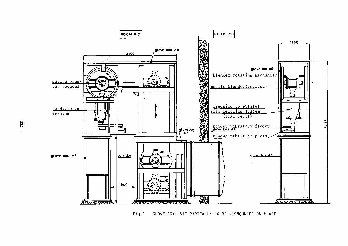
ro u to
1100
glove box A6
blender rotating mechanism
mobile blender(rotated)
feedsilo to presses silo weighing system
(load cells)
powder v i b r a t o r y f e e d e r flove box A4
transportbelt to press
glove box A7 glove box A7 ,
Fig 1 GLOVE BOX UNIT PARTIALLY TO BE DISMOUNTED ON PLACE

ro w
QUUJ
F i g . 2 GLOVE BOX LIFTING DEVICE

Glove box llano wesLgaskst
ro w
ÌZL
Glove box llano
<S / \ \ \ / IU shaoea gasxer / V V S À Pressure dividing leih
i / k W yj-\ ' ,.
■/\\\\]/
a : : ORIGINAL CONNECTION
Flat oaskel
Cut-*- -
3 Section AÃ'
§£SSSS£¿3-•— Smoli side
b : : FLAT CASKET AND FRAMEWORK IN L PROFIE
Glove box flana, U shaped gasket
s^^rø • — ^
(¿) Framework in L profilt
(s) Flot ggskel
(?) Tightening piece
@ Tape, adhesive on both sides
(p) PVC foil for plastic bag
(F) Clamping bolt
© Tope
© Pat gasket
(7) Pressing steel plate
© Clamping strip
(K) Clomping bolt
FIG. 3 SEPARATION OF 2 GLOVE BOX PARTS CONNECTED BY M.O. U-SHAPED GASKETS.

8.9. Melting of Radioactive Metal Scrap from the KRB-A Plant
Contractor: KRB Gundreminingen GmbH, Gundremmingen, Germany Contract N°; FI1D-0059 Working Period: July 1986 - December 1988 Project Leader: W. Stang
A. Objectives and Scope Radioactivity homogenisation and volume compaction of low-level
radioactive scrap can be achieved by melting. Then, depending on the average specific activity, the metal can be released to the general on the nuclear market, or stored for final disposal. However, melting in standard foundries without controlled containment atmosphere has to be limited to scrap with low specific activity (< 74 Bq/g), and large-scale experience with melting of higher-level radioactive metal scrap is presently not available.
The present research programme aims at collecting experience by large-scale melting of about 400 t of radioactive metal waste out of the KRB-A decommissioning, up to concentrations of 500 Bq/g.
The work will be executed with an induction-heated furnace (capacity ca. 3t) in the controlled zone of the KRB-A turbine building, probably after some backfitting of the existing filtration systems. The furnace will be leased, and is provided for reuse on another site.
The study will result in a clear statement if the above procedure has a potential for a large-scale application.
B. Work Programme B.1. Assessment of proposals for services from external contractors,
mainly concerning the leasing of an induction melting furnace. B.2. Definition of a work procedure, including the selection of represen
tative components for melting tests and of appropriate techniques for decontamination, dismounting and cutting, the definition of a procedure for the installation and operation of the melting furnace, and a preliminary planning for health physics protection.
B.3. Preparation of licensing procedures for the dismantling operations in the reactor building and for the installation and operation of a melting furnace.
B.4. Execution of the melting test programme, including decontamination for reducing the activity level (if needed), dismounting and conditioning of scrap into feeding drums, installation of the melting furnace and its auxiliary equipment, and execution of the main melting and casting programme, followed by an analysis of the prevailing radiation level during the melting operations.
B.5. Study of the final decommissioning of the melting furnace and the arising secondary waste.
B.6. Conclusive assessment of the usefulness of large-scale melting of metal scrap with a radioactivity level higher than 74 Bq/g.
- 235

C. Progresa of Work and Obtained Results
Summary Four different service companies have been asked for proposals concerning mainly leasing and operation of an induction melting furnace inside the controlled area of KRB unit A, The assessment of the proposals resulted in the decision that the necessary planning work for licensing, installation and cost-benefit-evaluation should be carried out by two independent engineering groups within about 6 months. Depending on the results of these activities at that time one service company will be choosen for the continuation of the program in the practical phase.
Progress and results
1. Assessment of proposals (B.I.) The proposals which have been asked by four different service companies for leasing and operating an induction melting furnace were devided into two phases: Phase 1 includes mainly the planning work for licensing, installation and cost-benefit-evaluation of the intended program (B.3.).
Phase 2 covers the following practical work beginning with the order of the melting furnace and ending with the conclusive assessment of the usefulness of large-scale melting in controlled areas (B.4. -B.6.). Because of quite different proposed concepts and costs it has been decided to contract two service companies (Noell, Würzburg, and Gesellschaft fur Nuclear Service (GNS), Essen) for executing phase 1. In October 1987 the contractor for phase 2 will be choosen depending on the results of phase 1.
2. Selection and preparation of plant components (B.2.)
The material which will be melted in the furnace has to be dismantled and cut into small pieces fitting in charging drums. For these activities the doserate of the personal has been calculated once assuming an in situ decontamination and once without predecontaraination. It can be expected that the in situ decontamination reduces the total job dose of the personal by a factor of 5. For this reason a concept of in situ system decontamination has to be worked out in the next step.
The following systems have been selected for the decontamination, dismantling and melting activities:
primary cleanup system shutdown cooling system control rod drive system recirculation loop 3 including secondary steam generator
- primary steam and feedwater piping.
236
8.10 Volume and Plutonium Inventories before and after Dismantling of a Mixed-oxide Fuel Plant
Contractor: Commissariat à l'Energie Atomique, CEN Cadarache, France Contract N": FIlD-0060 Working Period: May 1986 - October 1988 Project Leader: P. Gerontopoulos
A. Objectives and Scope Several plutonium processing lines belonging to the Fuel Fabrication
Complex of SFER-Cadarache (Service de Fabrication et d'Examens Radiomé-tallurgiques), have to be dismantled after long service, in the frame of plant modernisation. After disconnection from the ventilation ductwork and external utilities, the glove boxes and associated equipment are transported to the Waste Treatment Service of the Center, SPPC/SAR (Service de Protection, Prevention et ContrSle, Section d'Assainissement Radioactif) for dismantling, compacting and embedding in cement.
The importance of the plutonium quantities that have been processed in these now obsolete lines, the volume of the glove boxes to be dismantled and the variety of their functions make it of general interest to establish a balance of the volume and plutonium content of the arising wastes. These data will enable the evaluation of the waste management problems involved in the decommissioning of an industrial-size mixed-oxide fabrication facility as well as in defining novel design criteria for the construction of new facilities. Their collection and evaluation is the main objective of this research activity.
A conclusive assessment will give an answer as to whether the applied measuring and waste compacting techniques are appropriate for the present decommissioning task.
B. Work Programme B.1. Determination of the exact volume of the glove boxes to be dismantl
ed and description of the associated equipment. B. ?. Determination of the exact volumes of the wastes generated by the
dismantling. B.3. Preliminary estimation of the residual plutonium in the glove boxes
and associated equipment before dismantling. B.A. Measurement of the plutonium contained in the waste drums after
dismantling. B.5. Improvement of the existing plutonium monitoring techniques. B.6. Preparation of a conclusive assessment of the applied measuring
techniques, as well as a balance of involved volumes of waste and of masses of plutonium.
- 237
C. Progress of Work and Obtained Results Summary
This report describes dismantling work carried out before the end of 1986. This includes an important part of important preparatory work such as a specification outline of the dismantling procedures, risk evaluation, preparation of irradiation maps, plutonium recovery, fixation of the residual activity in the internal walls of the glove boxes etc. General information relative to the facilities is given in Table I.
The disconnection of the glove boxes belonging to these lines is almost completed but in some cases their transportation to SPPC/SAR for dismantling and waste conditioning is temporarily postponed because of the need of a more precise definition of their plutonium content and, eventually, further plutonium recovery. Consequently, a more precise estimation of the balance of the plutonium contaminated wastes will be possible only in the next reporting period.
Progress and Results 1. Organisation aspects
The lines to be dismantled are situated in the following SFKR facilities: ATPuSFECPu (Atelier Plutonium Section de Fabrication des Elements Combustibles au Plutonium) housed in building 258, in which finished mixed oxide fuel elements are fabricated starting from commercial U0„ and PuO powders and metallic structural components. LPCSCTCPu (Laboratoire de Purification Chimique Section de Contrôle et de Traitements des Combustibles au Plutonium), housed in Building 272, where impure, offspecification products or wastes are chemically processed for plutonium recovery and waste volume reduction. The decommissioning activities are performed under the direction of SFER within specific contractual arrangements with SPPC/SAR and STMI (Société de Travaux en Milieu Ionisant), a CEAEdF company specialised in work in radioactive environment. The responsibilities are shared as follows: preparation of the glove boxes and general technical assistance during
dismantling: SFECPu or SCTCPu dismantling: STMI transport: SPPC/SAR waste conditioning: SSPC/SAR.
The healthphysics surveillance in all phases of the decommissioning work is assured by the SPR (Service de Protection Contre les Rayonnements) .
The data presented here are based on contributions from all above mentioned services.
2. Plutonium monitored services (B.3., B.4.) Plutonium assaying in nonvoluminous packages leaving SFECPu and
SCTCPu for SPPC/SAR is routinely performed by coincidence passive neutron measurement of spontaneous fission events combined with the determination of the percentage of the even number of plutonium isotopes by gaimnaray spectometry. With the available instrumentation, the minimum detection limit of the plutonium content in a 100 litre waste drum corresponds to 100 mg.
Plutonium assaying in voluminous items (glove boxes, 870 litres waste drums etc.) that represent the major part of wastes arising from this decommissioning campaign, is more complex. A measuring apparatus (fig. 1) consisting of an ensemble of 83He total neutron counters fixed on a 2.5 m x 2.5 m mobile frame, able to scan at k 1Ţ geometry voluminous
238
items positioned on a 2.5 m x 3.5 m platform, was especially set up for monitoring this type of wastes and is first field-tested in the present campaign (B.3.). The correlation of the total neutron flux measured by the system to the quantity of plutonium is subiect to variations of plutonium isotopie composition, 241. content from 241p decay and the presence and distribution of chemical impurities favouring (ö(,n) reactions. In fact, cross check tests in which the plutonium content of voluminous waste items with the mobile frame apparatus are compared to those obtained after dismantling and conditioning in 100 litre drums counted by the routine coincidence technique show strong variations. The plutonium content of the waste packages leaving SFECPu/SCTCPu is measured by SPPC/SAR after dismantling and conditioning by passive gamma-essays.
3. Dismantling operation (B.I., B.2.) Disconnection of the glove boxes belonging to the processing lines
described in Table I has been almost terminated and a major part of the glove boxes and associated equipment has been transported to SPPC/SAR. Important plutonium quantities have been recovered during glove box preparation during dismantling. For example, in the pelletising line of LAB.2., SFECPu kilogram quantities of UO - PuO powders have been recovered during dismantling in spite of the fact tliat a cursory plutonium clean-up had taken place before disconnecting the line from the ventilation ductwork. In some cases (LAB.7. SFECPu and LAB. B-8,010 SCTCPu), excessive quantities of residual plutonium prove to constitute a burden for the decommissioning campaign due to the fact that the acceptance of the waste packages for dismantling at SPPC/SAR is conditioned to the presence of less than 300 g Pu in each waste package.
239 -

Table 1 SFECPu and SCTCPu processing Lines dismantled between 1.5.86 and 31.12.1986
IO
è
Product ion faci lity
SFECPu II
II
SCTCPu II
II
II
Lab
2
6 7
2 2
3
B-8,010
Function of the processing line/total quantity of plotonium processed, KG
Granulation line of UC^-PuQ^MOOO
Calcination of U02~Pu02/500
Calcination of U02~PuC>2 powder/1000
Powder transfer tunnel/7000
Glove boxes for miscellaneous use/50
Plutonium nitrate conversion by oxalate precipitation/300
Concentration of Pu (N03)¿, solution/300
Experimental facility for UC^-PuO? powder transfer/50
TOTAL:
N° of glove boxes
5 15 6
18 segments
1 2
2
8
39 glove boxes 18 segments
Total Volume (m3)
54 30 4,4 6,0
8 15,2
7,4
11,4
136,3

3 H« NEUTRON DETECTOR
PREAMPLIFIER
Fig. l - Mobile frame apparatus for passive t o t a l neutron measurements.
241

8.11 Decontamination, before Dismantling, of the Primary Coolant System of the RAPSODIE FBR
Contractor: Commissariat à l'Energie Atomiaue, CEN Valrho, France Contract N": FIlD-0061 Working Period: April 1986 - December 1988 Project Leader: J.R. Costes
A. Objectives and Scope The large-scale decontamination of FBR sodium loops is an original
task, since only a limited number of results with laboratory-scale work is available, so far.
The principal aim of the present contract is the development of an appropriate decontamination procedure and its application to the primary loops of the RAPSODIE FBR in the framework of its Stage 2 decommissioning.
The procedure is developed in a pilot facility, allowing to treat representative samples and providing the selection of an efficient decontaminant, but also with special care in minimising and treating the secondary waste.
After disconnecting the pipework from the main vessel, pipes will be treated by circulating chemical solutions, and containers by spraying liquids or gels.
B. Work Programme B.1. Characterisation of the primary reactor loops to be decontaminated,
including size and nature of structures and type and degree of contamination.
B.2. Construction and commissioning tests of the pilot decontamination loop GROLABO.
B.3. Decontamination tests in the GROLABO facility, aimed at an optimisation of procedures and of secondary waste treatment.
B.4. Safety analysis for the decontamination of the primary reactor loops and ordering of needed equipment.
B.5. Adaptation of the primary reactor loops, including isolation from the reactor vessel and equipment with specific components and instrumentation.
B.6. Assessment of the above developed decontamination procedures and decontamination of the isolated primary reactor loops.
B.7. Treatment of effluents. B.8. Final assessment of obtained results and recommendations for future
work.
- 242

C. Progresa of vork and obtained results
Summary In the first part of this study are successively examined :
- the best means to decontaminate the reactor main circuits ; - circuits characteristics i.e. metal nature, size, running temperature
conditions ; - contamination and irradiation data ; - décontamination efficiency of some reagents.
Progress and results Work in this year was mainly devoted to the characterisation of the primary Loop to be decontaminated (B.I) 1. Size and nature of Rapsodie reactor structures
The cooling of reactor (40 liUth of thermic power) was made by two identical North and South circuits. Each one exhausted its power by the mean of an intermediate sodium exchanger (EIS and EIN) through a primary pump (PP2 and PP3).
These main circuits, which are under double jacket, and the core containment are surrounded by several auxiliary circuits, having the following purposes : - leak detections ; - circuits reheating before start up or safety recooling in case of primary
cooling shut down ; - sodium purification ; - neutral gases supply of - shield cooling, primary sodium cold trap cooling ; etc.
Figures 1 and 2 show the circuits arrangment and the synoptic. The decontamination of all these circuits before their dismantling, is
the aim of this project.
Geometric data The geometric data, for the North or for the South circuit, are :
- between main vessel and exchanger : 300/314 mm of diameter, 16 m long with a part not concerned by the decontamination ; between exchanger and pump : 300/314 mm diameter, 8.5 m long ;
- between pump and "Y" : 300/314 mm diameter, 8.5 m long ; exchanger tank dimensions : 884 mm diameter ; 5.2 m high ; pump tank dimensions : 850 mm diameter ; 4.5 m high.(see TABLE I)
Thermic data In a simplified manner, we can consider several sodium circuit groups,
according to their nominal running temperature : 500'C :
- between the reactor exit and the primary exchangers, with the upper part of the exchanger tank ; - the overflow tank, with its connexion with the main vessel and the
purification board ; 400'C :
- part of primary circuit between the overflow tank and "saxophone" and the lower part of exchanger tanks and primary pumps.
Metallurgie data These circuits are made of austinitic stainless steel 316L or 316 Ti.
243

Sodium level In each tank, there was a given sodium level, above which was a neutral
gas blanket. The liquid-gas interface has a specific contamination.
2. Contamination data From EIS and PP Na samples analysis, three spectral compositions are
presented on TABLE II. Uith a contamination mean level of 10000 Bq/cm*, the total radioactivity contain is estimated at : 104 * 286 * 104 = 2,9.1010 Bq
3. Preliminary Laboratory works extracts made in Cadarache These tests are not included in this CEC contract. However, they are
summed up here, because they will be useful to understand the pilot experiments. They were carried on little samples cut out of intermediate exchangers, primary pump, overflow tank.
Eroaion tests by chemical reagents The main conclusion of erosion tests carried on inactive samples of the
same metallurgie nature, are : - fluotrinic mixture erodes up to 4 /im/h and diminishes the sample brightness - oxalosulfuric mixture is a little more agressive and partially removes
the brightness; - oxygenated water addition in this last mixture controles the erosion.
Decontamination tests The best results were obtained with the following reagents :
- fluonitric when cold, - oxalic-8ulfuric-oxygenated water, when hot, - sulfonitric when cold or hot.
A preliminary treatment with caustic soda, enhances the results, by removing grease deposits, specially in gas zones.
The residual activity goes from 3 to 200 Bq/cm*. Next tests will be made in a pilot unit, called "GROLABO" which will be
the object of next report.
4. First study on a part of circuit decontamination The decontamination operation will be divided in eight or ten
elementary operations called "loops". The circulation scheme foreseen for "the overflow tank RE Na 301 loop"
is representative of the other Loops schemes. It includes :
i filling the RE Na 301 tank bottom by reagents by pumping from the Re Na 300 large tank, lower point of the plant. A specific pump (PPal 463) will be installed,
ii pipe decontamination of the loop, by reagents circulation, by the mean of PPal 463 (see figure 2).
iii sprinkling decontamination in the inside of the overflow tank Re Na 301 (see figure 2).
These three steps are called "configuration". For each one, we have listed straight lines, bends, valves and other pecularities ; then a computer software give us the working point of the pump, and Reynolds number. The TABLE III sums up the results.
These data will be useful to fix the working parameters of GROLABO pilot unit.
- 244

TABLE I - ESTIMATED VOLUMES AND SURFACES
! Each primary loop with ! associated tank ! Over flow tank (RE Na 301) ! Storage tank (RE Na 300) ! Little sodium circuits ! Blanket gas circuits
! TOTAL
Volume (m3)
8.6 10 40 2 1 62
Area (m") !
2 x 60 !
31 ! 65 ! 50 ! 20 !
286 ! !
TABLE II - CONTAMINATION DATA
! ! contamination mean level !
! 1 24000 Bq/cm2 ! 4500 Bq/cm« ! 5500 Bq/cm" ! ! ! gas zone ! cold sodium zone ! Hot sodium zone !
! H3 ! - ! 2 *< ! - ! ! Mn 54 ! 2 \ ! 40 * ! 24 % ! ! Co 60 ! 1 % ! 4 \ \ 6 % ! ! Ni 63 ! - ! 25 % ! 15 % ! ! Sr 90 ! - ! 9 % ! 2 % ! ! Cs 134 ! 1 % ! - ! 1 % ! ! Cs 137 ! 96 \ ! 20 \ ! 52 * ! ! ! ! ! !
TABLE III - CONFIGURATION
! ! Flovrate ! Speed (m/s) ! Reynolds number ! ! Configuration ! m3/h ! minimum ! maximum ! minimum ! maximum ! ! ! ! ! ! ! ! ! ! ! ! ! ! ! ! Filling ! 6.3 ! 1.6 ! 1.9 ! 1,5 .10* ! ! Circulation J 4.5 ! 0.15 ! 4.3 ! 3.6.104 ! 2.103 ! ! Sprinkling ! 3.6 ! ! 0.6 ! ! 1900 ! ! ! ! ! ! ! !
- 245 -
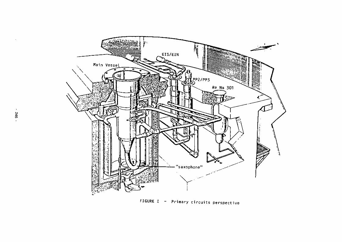
IO ■o.
FIGURE I - Primary circuits perspective

r~r-~T ^ L ' - Ţ i ^ » - ^ ^
IV) J
Re Na 301
FIGURE 2 - Overflow tank Re Na 301 Loop decontaminations circulation and sprinkling decontamination configuration.

8.12 Automated Measuring System for Waste from Dismantling of the KKN Plant, to be Released
Contractor: Nuklear-Ingenieur-Servlce GmbH, Hanau Contract N°: FI1D-0062 Working Period: May 1986 - April 1988 Project Leader: I. Auler
A. Objectives and Scope An important task in the decommissioning of nuclear installations is
the proof of very low radioactivity levels, allowing for free release of the generated waste. This proof involves long measuring times on a great number of representative samples out of important masses of metal structures and concrete, and considerable radiation exposure of the measuring staff.
The main objective of the present research is the development, construction and large-scale testing of a prototype for an automatic measuring system, appropriate to treat important masses of waste, with low-level activities and different nuclide compositions and shapes. It is expected to minimise human errors by automatic operation.
The measuring system will be designed as a mobile unit, with a modular structure allowing for a general purpose application to LWR typical waste arisings, at different decommissioning sites. The practical testing will be done with a total mass of 1000 Mg in the framework of the KKN decommissioning.
The study will be completed by a conclusive assessment of the merits of the developed measuring system for large-scale operation.
B. Work Programme B.1. Conceptual studies for the definition of the requirements for a
measuring system, including assessment of existing low-level activity measuring techniques, definition of the types of waste to be treated, and health physics protection considerations.
B.2. Preparation of a design of the complete measuring system, including detectors, control and transport system, general purpose software for measuring data processing, followed by a call for tenders and the choice of manufacturers.
B.3. Preparation of a licensing dossier for experimental operation of the measuring system in the framework of the decommissioning of KKN.
B.4. Execution of a large-scale test programme. B.5. Conclusive assessment of the appropriateness of the developed
measuring system, considering technical and economic aspects.
248

C. Progress of Work and Obtained Results
Summary Databank and literature investigations have shown that at
the present state of technology adequate systems for the object of this research program do not exist.
The measurement conditions depending on the kind of wastes to be treated were defined. Wastes have been classified by nuclide spectra measurements. The measuring equipment was roughly designed and the measuring requirements were specified. Several detector systems can fulfill these requirements. Calculations to study the sensitivity of the measuring devices were performed. A devision which detector system represents the most adequate solution will be taken during the next working period.
Progress and Results 1. Definition on requirements for a measuring system (B.l.)
Assessment of existing low level activity measuring technics Databank and literature investigations have shown that at
the present state of technology adequate systems for the object of this research program do not exist.
Dismantling of a 1300 MWe BWR will generate about 16.000 Mg of de contaminat) l e or very low-level radioactive wastes for which an unrestricted release may be proven by measurements. For a 1300 MWe PWR about 7.000 Mg are to be expected. In case of KKN these wastes will amount to about 815 Mg.
Figure 1 shows the total mass of dismantling wastes and the portion of decontaminable and releasable wastes. Most of this material consits of steel used in structures and shiel-dings. In Table I the main waste materials are listed. Nuclide spectra have been measured at contaminated and activated components.
In every nuclide spectrum Co-60 could be identified. Because of its typical gamma-energies (1,332 MeV and 1,173 MeV) Co-60 was chosen as the reference nuclide for detection of radioactivity.
Because of the very low level of the detectable activity the monitoring systems must be able to detect 0,03 Bq/cm2 taking into consideration that
only 50 % of the radioactivity will be Co-60 the self shielding attenuation factor is 0,3 (corresponding to a steel thickness of 2-3 cm) an additional security factor is required.
The limit for unrestricted release of contaminated materials, given by the German Radiation Protection Ordinance, is 0,37 Bq/cm2.
249

It is expected that any radioactivity of this level will be detected meeting the conditions mentioned above.
2. Preparation of a design of the complete measuring system (B.2.) In addition the monitoring system has to meet the follo
wing requirements: - Total capacity of one measuring campaign 800 Mg
Weight of one measuring batch 1 Mg - Measuring time for one batch about 1 minute - Manpower minimization
The consideration of parts to be measured showns that a measuring chamber of 1 m width and 0,8 m hight is required. For measuring pipes longer than the measuring chamber it has to be open at the front and back side.
Various detector systems which meet the specifications have been offered. Figures 2-5 show the different configurations and principles of the considered scintillation counters. A decision which of them will be the most suitable will be taken after an evaluation of measuring results.
- 250

Table I Mass and Surface of contaminated components of NPP Niederaichbach
Component
Pipings Valves Tanks Control Rod Drives Plug Boxes Cable Ducts Heat Insulations (100 cm Thickness) Insulation Plates Steel Parts Press Stones
Mass /Mg/
37 6 7 5 10 42 46
40 362 260
Surface An
2/
3912 150 92 30 183 975 5520
1455 5062 2397
Surface/Mass 2
lc.aTIV.gl
470 250 130 60 180 230 1200
370 140 90
Total 815 19776 243
19.000 -
J 10.000
2.500 -
8S y. ' f r e e '
70 X - f r e e '
V/////U* ■«
Figure 1: Portions of releasable masses
251

ro en io
Figure 2: Configuration of partly lowerable detectors (Supplier A)
Figure 3: Configuration of NaJ-detectors (Supplier B)

IO Ol G)
Figure 4: C o n f i g u r a t i o n of s e a l e d l i q u i d s c i n t i l l a t o r d e t e c t o r s (Supp l i e r C)
F igure 5: Conf igura t ion of p l a s t i c s c i n t i l l a t i o n d e t e c t o r s (Supp l i e r D)

ANNEX I
LIST OF PUBLICATIONS RELATING TO THE RESULTS OF THE 1979-83 PROGRAMME ON THE DECOMMISSIONING OF NUCLEAR POWER PLANTS
A. Annual Progress Reports
"The Community's Research and Development Programme on Decommissioning of Nuclear Power Plants - First Annual Progress Report (year 1980)", EUR 7440, 1981.
"The Community's Research and Development Programme on Decommissioning of Nuclear Power Plants - Second Annual Progress Report (year 1981)", EUR 8343, 1983.
"The Community's Research and Development Programme on Decommissioning of Nuclear Power Plants - Third Annual Progress Report (year 1982)", EUR 8961, 1984.
"The Community's Research and Development Programme on Decommissioning of Nuclear Power Plants - Fourth Annual Progress Report (year 1983)", EUR 9677, 1985.
B. 1984 European Conference
Schaller, K.H., Huber, B. (ed). Decommissioning of nuclear power plants - Proceedings of a European Conference held in Luxembourg, 22-24 May 1984. Graham & Trotman Ltd, London. EUR 9474 EN.
C. Final Contract Reports
Boothby, R.M., William, T.M. (1983). The control of cobalt content in reactor grade steels. European Appi. Res. Rept., Nuci. Sci. Technol. Vol. 5, No. 2, Harwood Academic Publishers. EUR 8655.
Lörcher, G., Piel, W. (1983). Dekontamination von Komponenten stillgelegter Kernkraftwerke für die freie Beseitigung. EUR 8704.
Kloj, G., Tittel, G. (1984). Thermische und mechanische Trennverfahren für Beton und Stahl. EUR 8633.
Harbecke, W. et al. (1984). Die Aktivierung des biologischen Schilds im stillgelegten Kernkraftwerk Lingen. EUR 8801.
Verrai, S., Fitzpatrick, J. (1985). Design concepts to minimize the activation of the biological shield of light-water reactors. EUR 8804.
Eickelpasch, W. et al. (1984). Die Aktivierung des biologischen Schilds im stillgelegten Kernkraftwerk Gundremmingen Block A. EUR 8950.
Verry, P., Lecoffre, Y. (1984). Decontamination de surfaces par érosion de cavitation. EUR 8956.
254

Allibert, M., Delabbaye, F. (1984). Extraction du cobalt des aciers inoxydables. EUR 8966.
Ebeling, W. et al. (1984). Dekontamination von Betonoberflächen durch Flammstrahlen. EUR 8969.
Boulitrop, D., Rouet, D. (1984). Etude de la décontamination au moyen de supports gélifiés. EUR 9102.
Peselli, M. (1984). Individuazione quantitativa delle impurezze del contenitore a pressione del reattore del Garigliano. EUR 9167.
Avanzini, P.G. et al. (1984). Valutazione delle caratteristiche di progetto che facilitano lo smantellamento delle centrali nucleari PWR. EUR 9191.
Regan, J.D. et al. (1984). Design features facilitating the decommissioning of Advanced Gas-cooled Reactors. EUR 9207.
May, S., Piccot, D. (1984). Détermination analytique d'éléments traces dans des échantillons de bétons utilisés dans les réacteurs nucléaires de la Communauté européenne. EUR 9208.
White, I.F. et al. (1984). Assessment of management modes for graphite from reactor decommissioning. EUR 9232.
Goddard, A.J.H, et al. (1984). Trace element assessment of low-alloy and stainless steels with reference to gamma activity. EUR 9264.
Bregani, F. et al. (1984). Chemical decontamination for decommissioning purposes. EUR 9303.
Glock, H.-J. et al. (1984). Dokumentationssystem für den Abbau von Kernkraftwerken. EUR 9343.
Ahlfänger, W. (1984). Zusammensetzung von Kontaminationsschichten und Wirksamkeit der Dekontamination. EUR 9352.
Brambilla, G. et al. (1984). Vernici per la fissazione della contaminazione superficiale dei materiali. EUR 9358.
Paton, A.A. et al. (1984). Civil engineering design for decommissioning of nuclear installations. Graham & Trotman Ltd, London. EUR 9399.
Bittner, A. et al. (1985). Konzepte zur Minimierung der Aktivierung des biologischen Schilds. EUR 9442.
Brambilla, G., Beaulardi, L. (1985). Rivestimenti rimovibili per la protezione di superfici in calcestruzzo dalla contaminazione. EUR 9463.
Arndt, K.-D. et al. (1984). Thermisches Trennen von plattierten Komponenten des Primärkreises von Kernkraftwerken. EUR 9479.
Rawlings, G.W. (1985). Development of large diamond-tipped saws and their application to cutting large radioactive reinforced concrete structures. EUR 9499.
255

Barody, I.I. et al. (1985). Treatment of active concrete waste arising from dismantling of nuclear facilities. EUR 9568.
Bernard, A., Gerland, H. (1985). Recherche et caractérisation de revêtements pour la protection des structures en béton. EUR 9595.
De Tassigny, Ch. (1985). Mise au point et essais d'une méthode pour le revêtement de déchets métalliques contaminés, par des résines thermo-durcissables. EUR 9666.
Migliorati, B. et al. (1985). Smantellamento di componenti metallici e di strutture in calcestruzzo mediante raggio laser. EUR 9715.
Fleischer, C.C. (1985). A study of explosive demolition techniques for heavy reinforced and prestressed concrete structures. EUR 9862.
Wieling, N., Hofmann, P.J. (1985). Erosionskorrosionsversuche mit kobaltfreien Werkstoffen. EUR 9865.
Antoine, P. et al. (1985). Intégrité à long terme des bâtiments et des systèmes. EUR 9928.
Lewis, G.H. (1985). Degradation of building materials over a life span of 30-100 years. EUR 10020.
Hasselhoff, H., Seidler, M. (1985). Anlage zum Einschmelzen von radioaktiven metallischen Abfällen aus der Stillegung. EUR 10021.
Chavand, J. et al. (1985). Découpage de composants métalliques par fissuration intergranulaire. EUR 10037.
Gauchon, J.P. et al. (1986). Décontamination par des méthodes chimiques, électrochimiques et au jet d'eau. EUR 10043.
Smith, G.M. et al. (1985). Methodology for evaluating radiological consequences of the management of very low-level solid waste arising from decommissioning of nuclear power plants. EUR 10058.
Gomer, C.R., Lambley, J.T. (1985). Melting of contaminated steel scrap arising in the dismantling of nuclear power plants. EUR 10188.
Da Costa, L. et al. (1985). Review of systems for remotely controlled decommissioning operations. Graham & Trotman Ltd, London. EUR 10197.
Price, M.S.T., Lafontaine, I. (1985). System of large transport containers for waste from dismantling light water and gas-cooled nuclear reactors. EUR 10232.
Bargagliotti, A. et al. (1986). Plasma arc and thermal lance techniques for cutting concrete and steel. EUR 10402.
Lasch, M. (1986). Entwicklung von wirtschaftlichen Dekontaminationsverfahren. EUR 10519.
Hulot, M. et al. (1986). State-of-the-art review on technology for measuring and controlling very low-level radioactivity in relation to the decommissioning of nuclear power plants. EUR 10463.
256

ANNEX II
MEMBERS OF THE MANAGEMENT AND COORDINATION ADVISORY COMMITTEE NUCLEAR FISSION ENERGY
FUEL CYCLE/PROCESSING AND STORAGE OF WASTE (1)
(during 1986)
BELGIUM M. ALLE (2) H. MATTHIJS J.P. PONCELET (3)
DENMARK K. BRODERSEN T. NILSEN
FRANCE J. LEFEVRE (Chairman) J.-C. MOUGNIOT
GERMANY R. GORGEN K. HUBENTHAL
GREECE S. AMARANTOS M. DOMIS-ANTONOPOULOS
IRELAND J. CUNNINGHAM F. Tl'RVEY
ITALY F. MOPSELLI P. VENDITTI
LUXEMBOURG P. KAYSER
NETHERLANDS J.C. BAAS (3) H. CORNELISSEN (2) A. GEVERS
PORTUGAL H.J.P. CARREIRA PICH C. RAMALHO CARLOS
SPAIN G. MADRID J.M. VALVERDE MUFLA
UNITED KINGDOM P.H. AGRELL (2) F.S. FEATES G.H. STEVENS (3)
COMMISSION S. FINZI J. VAN CEEL
(D
(2) (3)
This Committee was established by the Council Decision of 29 June 1984 dealing with structures and procedures for the management and coordination of Community research, development and demonstration activities (OJ N° L 177, 4. 7. 1984, p. 25). Entered in 1986. Retired in 1986.
257


European Communities — Commission
EUR 11112 — The Community's research and development programme on decommissioning of nuclear installations — Second annual progress report (year 1986)
Luxembourg: Office for Official Publications of the European Communities
1987 — VII, 257 pp., 96 Fig., 45 Tab. — 21.0 x 29.7 cm
Nuclear science and technology series
EN
ISBN 92-825-7385-0
Catalogue number: CD-NA-11112-EN-C
Price (excluding VAT) in Luxembourg: ECU 19.80 BFR 850 IRL 15.30 UKL 13.90 USD 22.60
This is the second annual progress report of the European Community's programme (1984-88) of research on the decommissioning of nuclear installations. It shows the status of the programme on 31 December 1986. This second progress report describes the objectives, scope and work programme of the 58 research contracts concluded, as well as the progress of work achieved and the results obtained in 1986.
llllllllllllllillllllllll


Venta y suscripciones • Salg og abonnement • Verkauf und Abonnement • nuÅnoeic Kai ouvSpouéq Sales and subscriptions • Vente et abonnements • Vendita e abbonamenti
Verkoop en abonnementen • Venda e assinaturas
BELGIQUE/BELGIË FRANCE NEDERLAND
Moniteur belge/Belgisch Staatsblad Rue de Louvain 40-42/Leuvensestraat 40-42 1000 Bruxel les/ 1000 Brussel Tél. 512 00 26 CCP/Postrekening 000-2005502-27
Sous-dépôts / A g e n t schappen: Librairie e u r o p é e n n e / Europese Boekhandel Rue de la Loi 244 /Wets t raa t 244 1040 Bruxel les/ 1040 Brussel
CREDOC Rue de la Montagne 34/Bergst raat 34 Bte 1 1 / B u s 11 1000 Bruxel les/ 1000 Brussel
DANMARK
Schultz EF-publikationer Mentergade 19 1116 København K Tlf: (01) 14 11 95 Telecopier: (01) 32 75 11
BR DEUTSCHLAND
Bundesanzeiger Verlag Breite Straße Postfach 10 80 06 5000 Köln 1 Tel. (02 21) 20 29-0 Fernschreiber: ANZEIGER BONN 8 882 595 Telecopierer: 20 29 278
GREECE
G.C. Eleftheroudakis SA International Bookstore 4 Nikis Street 105 63 Athens Tel. 322 22 55 Telex 219410 ELEF
Sub-agent for Northern Greece: Molho's Bookstore The Business Bookshop 10 Tsimiski Street Thessaloniki Tel. 275 271 Telex 412885 LIMO
ESPANA
Boletín Oficial del Estado Trafalgar 27 28010 Madr id Tel. (91) 446 60 00
Mundi-Prensa Libros, S.A. Castellò 37 28001 Madr id Tel. (91) 431 33 99 (Libros)
431 32 22 (Suscripciones) 435 36 37 (Dirección)
Télex 49370-MPLI-E
Journal officiel Service des publications des Communautés européennes 26. rue Desaix 75727 Paris Cedex 15 Tél. (1 )45 78 61 39
IRELAND
Government Publications Sales Office Sun Alliance House Molesworth Street Dublin 2 Tel. 7 1 0 3 09
or by post Government Stationery Office Publications Section 6th floor Bishop Street Dublin 8 Tel. 78 16 66
ITALIA
Licosa Spa Via Lamarmora, 45 Casella postale 552 50 121 Firenze Tel. 57 97 51 Telex 570466 LICOSA I CCP 343 509
Subagenti: Libreria scientifica Lucio de Biasio - AEIOU Via Meravigli, 16 20 123 Milano Tel. 80 76 79
Libreria Tassi Via A. Farnese. 28 00 192 Roma Tel. 31 05 90
Libreria giuridica Via 12 Ottobre. 172/R 16 121 Genova Tel. 59 56 93
GRAND-DUCHÉ DE LUXEMBOURG et autres pays /and other countries
Office des publications officielles des Communautés européennes 2, rue Mercier L-2985 Luxembourg Tél. 49 92 81 Télex PUBOF LU 1324 b CCP 19190-81 CC bancaire BIL 8 -109 /6003 /200
Abonnements /Subscript ions
Messageries Paul Kraus 11, rue Christophe Plantin L-2339 Luxembourg Tél. 49 98 888 Télex 2515 CCP 49242-63
Staatsdrukkerij- en uitgeversbedrijf Christoffel Plantijnstraat Postbus 20014 2500 EA 's-Gravenhage Tel. (070) 78 98 80 (bestellingen)
PORTUGAL
Imprensa Nacional Casa da Moeda, E. P. Rua D. Francisco Manuel de Melo, 5 1092 Lisboa Codex Tel. 69 34 14 Telex 15328 INCM
Distribuidora Livros Bertrand Lda. Grupo Bertrand, SARL Rua das Terras dos Vales, 4-A Apart. 37 2700 Amadora CODEX Tel. 493 90 50 - 494 87 88 Telex 15798 BERDIS
UNITED KINGDOM
H M Stationery Office HMSO Publications Centre 51 Nine Elms Lane London SW8 5DR Tel. (01) 211 56 56
Sub-agent: Alan Armstrong & Associates Ltd 72 Park Road London NW1 4SH Tel. (01) 723 39 02 Telex 297635 AAALTD G
UNITED STATES OF AMERICA
European Community Information Service 2100 M Street. NW Suite 707 Washington, DC 20037 Tel. (202) 862 9500
CANADA
Renouf Publishing Co., Ltd 61 Sparks Street Ottawa Ontario K IP 5R1 Tel. Toll Free 1 (800) 267 4164 Ottawa Region (613) 238 8985-6 Telex 053-4936
JAPAN
Kinokuniya Company Ltd 17-7 Shinjuku 3-Chome Shiniuku-ku Tokyo 160-91 Tel. (03) 354 0131
Journal Department PO Box 55 Chitóse Tokyo 156 Tel. (03 )439 0124
10/86

NOTICE TO THE READER
All scientific and technical reports published by the Commission of the European Communities are announced in the monthly periodical 'euro abstracts'. For subscription (1 year: BFR 3 300) please write to the address below.
Price (excluding VAT) in Luxembourg ECU 19.80 BFR 850 IRL 15.30 UKL 13.90 USD 22.60
* * . OFFICE FOR OFFICIAL PUBLICATIONS * -sfa \ OF THE EUROPEAN COMMUNITIES
* * * L—2985 Luxembourg
ISBN TS-ñES-VBñS-Q