Embed Size (px)
Citation preview

ISSN 1018-5593
Commission of the European Communities
energy
EUROPEAN SOLAR TEST INSTALLATION (ESTI)
QUALIFICATION TEST PROCEDURES FOR CRYSTALLINE
SILICON PHOTOVOLTAIC MODULES
Report EUR 13897 EN
Blow-up from microfiche original


s ISSN 1018-5593
Commission of the European Communities
energy
EUROPEAN SOLAR TEST INSTALLATION (ESTI)
QUALIFICATION TEST PROCEDURES FOR CRYSTALLINE
SILICON PHOTOVOLTAIC MODULES
H. OSSENBRINK, E. ROSSI Commission of the European Communities
Joint Research Centre Institute for Systems Engineering and Informatics
Ispra Establishment 1-21020 Ispra (VA)
FINAL REPORT
Directorate-General Science, Research and Development
Joint Research Centre
1992
PARI. EUROP. Bibliotf,.
N.C EUR 13897 Ef

Published by the COMMISSION OF THE EUROPEAN COMMUNITIES
Directorate-General Telecommunications, Information Industries and Innovation
L-2920 LUXEMBOURG
LEGAL NOTICE
Neither the Commission of the European Communities nor any person acting on behalf of the Commission is responsible for the use which might be made of the following
information
Catalogue number: CD-NA-13897-EN-C
© ECSC — EEC — EAEC, Brussels - Luxembourg, 1992

I I I
Printing History
Qualification Test Procedures for Photovoltaic Modules Draft Specification N"503 Version 1.0 June 1989 (not for publication)
Qualification Test Procedures for Crystalline Silicon Photovoltaic Modules Specification N·503 Version 2.0 Dec. 1989 (JRC Preprint-For Internal Use Only)
Qualification Test Procedures for Crystalline Silicon Photovoltaic Modules Specification N ·503 Version 2.1 May 1990 (JRC Preprint)
Qualification Test Procedures for Crystalline Silicon Photovoltaic Modules Specification N "503 Version 2.2 March 1991 (JRC Publication)


CONTENTS
SPECIFICATION N*503
1 2 3 4 5 6 7
Introduction Scope Objectives List of Source Documents Comparison with Specification 502 Acknowledgements Additional Information
ANNEX A: TEST REQUIREMENTS
A1 A2 A3 A4 A5 A6 A7 A8 A9
Introduction Purpose Sampling Marking Testing Pass Criteria Major Visual Defects Report Modifications
Page
ANNEX B: TEST PROCEDURES
B1 Visual Inspection 11 B2 Performance at STC 12
B3 Insulation 13 B4 Measurement of Temperature Coefficients 14 B5 Measurement of Nominal Operating Cell Temperature (NOCT) 16 B6 Performance at NOCT 19 B7 Performance at Low Irradiance 19 B8 Outdoor Exposure 2 0 B9 Hot Spot Endurance 21 B10 UV Exposure 2 7 B11 Thermal Cycling 28 B12 Humidity-Freeze 30 B13 Damp-Heat 3 2 B14 Robustness of Terminations 3 3 B15 Twist 3 5 B16 Mechanical Load 3 6 B17 Hail Resistance 3 7
VI
TABLES
Table I Summary of Test Levels 8
Table II Ice Ball Masses and Test Velocities 3 9
ILLUSTRATIONS
Fig.l Qualification Test Sequences 9 Fig.2 NOCT Correction Factor 18 Fig.3 Hot Spot Effect in Type A Cell 21 Fig.4 Reverse Characteristics 2 2 Fig.5 Hot Spot Effect in Type B Cell 2 2 Fig.6 Case SP: Series-Parallel Connection 2 3 Fig.7 Case SPS: Series-Parallel-Series Connection 2 3 Fig.8 Thermal Cycling Test 2 9 Fig.9 Humidity Freeze Cycle 31 Fig.10 Hail Test Equipment 3 8 Fig.ll Impact Locations Illustrated 3 9

1. INTRODUCTION
This recommendation lays down the control tests of the Commission of the European Communities, applied by the Joint Research Centre for the qualification of crystalline silicon photovoltaic (PV) modules used in projects funded by the Commission, or upon special request from industry or other organizations.
The general objective of these tests is to assess relative performances and to identify environmental factors and design features which could affect the attainment of a sufficiently long life-time. A similar specification applicable to thin-film technology is in preparation under the designation 701.
2. SCOPE
This document is issued for the purpose of updating previous specifications of the Commision's Joint Research Centre, such as the Specifications 501 and 502. Performance and qualification tests have been revised in order to adjust for terrestrial PV module technology developments and to take into account a growing knowledge from field experience.
3. OBJECTIVES
With the increased number of installed PV systems in the past years the need for international agreeable standards on performance and reliability tests became obvious. The International Electrotechnical Commision (IEC), Geneva, is drafting since 1983 within its Technical Committee 82, Working Group 2 (PV Modules), documents for measurement and qualification, which are based to a large extent on existing specifications. These draft documents represent today the best common denominator achievable between experts from numerous countries.
Being a test laboratory of the Commission of the European Communities, the European Solar Test Installation (ESTI) of the Joint Research Centre is committed to both pre-normative contributions to the harmonisation of standards and execution of tests for PV devices. In this respect ESTI provides expertise to the IEC work and has strong interest in implementing widely agreed test procedures.
ESTI decided to update the existing Specifications 501 (1981) and 502 (1984), because the experience acquired with modules deployed in real conditions allowed the implementation of more specific failure simulations and the development of appropriate and sophisticated equipment.
As in the near future a Standards publication of the IEC and/or CENELEC can be expected, ESTI tries now to align with the considered tests and test sequences in order to
a) validate experimentally the Standards proposals for the benefit of a wide technical acceptance
b) ensure the industry as far as possible that devices qualified to-day in accordance with this Specification 503 will pass future IEC and/or CENELEC Standards as well.
Therefore the herewith presented Specification 503 in its Version 2.2 contains purely documents drafted within the IEC TC82 Working Group 2 and shall be considered only as a description of procedures, which ESTI will follow until an official Standards Publication is issued. The tests and schedules described will be executed as an alternative to those of the Specification 502.
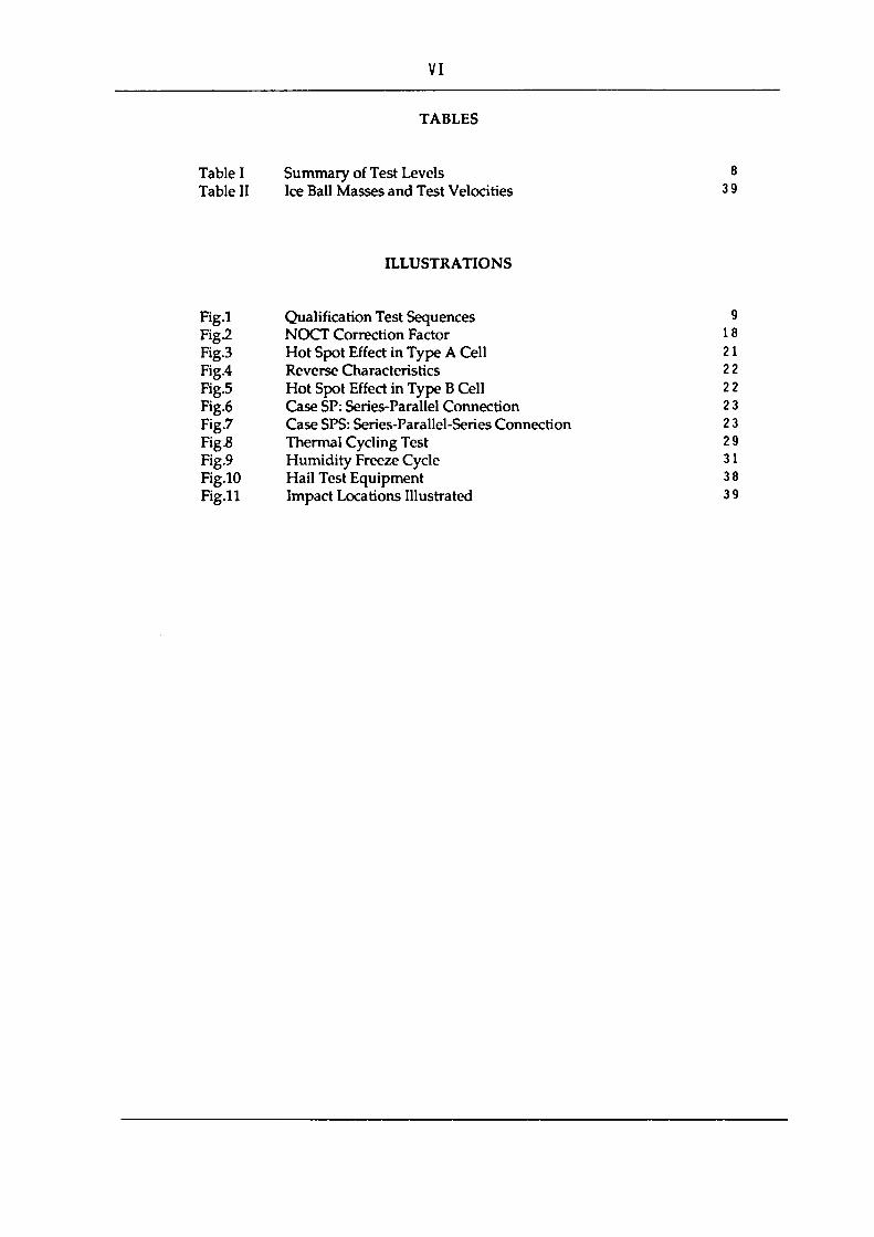
4. LIST OF SOURCE DOCUMENTS
The following IEC TC82 WG 2 documents have been taken as source for this Specification 503:
Document Designation
82 /WG2 (Secretary)142, 82 /WG2 (Secretary)53, 82 /WG2 (Secretary)95, 82 /WG2 (Secretary)143, 82 /WG2 (Secretary)133, 82 /WG2 (Secretary)155, 82 /WG2 (Secretary)104+135, 82 /WG2 (Secretary)154, 82 /WG2 (Secretary)67, 82 /WG2 (Secretary)152, 82 /WG2 (Secretary^, 82 /WG2 (Secretary)68, 82 /WG2 (Secretary)54, 82 /WG2 (Secretary)153, 82 /WG2 (Secretary)136, 82 /WG2 (Treble)28
Issue Date
11/1988 05/1985 12/1986 11/1988 06/1988 03/1989 10/1988 03/1989 12/1985 03/1989 04/1986 12/1985 05/1985 03/1989 11/1988 07/1989
Source for
Part A Test Bl Test B3 Test B4 Test B5 Test B8 Test B9 Test B10 TestBll Test B12 Test B13 Test B14 Test B15 Test B16 Test B17 Tests B2,B6, B7
The character fonts of the following Annex A (Test Requirements) and Annex B (Test Procedures) have the following significance:
Text printed in HELVETICA indicates test procedures taken from the above documents and implemented at ESTI.
Text printed in HELVETICA Italic indicates procedures taken from above documents, which will be implemented at ESTI in the near future (during the year 1991).
5. COMPARISON WITH SPECIFICATION 502
Fig.1 shows the layout of the proposed test sequence for crystalline silicon photovoltaic module qualification tests. The scheme compromises between a schedule where each single module undergoes only one specific experiment (as it is the case in the Spec.502) and a schedule where all samples are subjected to all specific tests subsequentially. This allows a better statistics of failures but maintains a practical time schedule for the test laboratory.
The following tests have been added compared to Spec.502:
B7 Performance at Low Irradiance
This additional measurement provides the manufacturer and user with valuable data necessary for the system design of low-irradiance critical applications as e.g. pumping stations or maximum-power-point tracking.
B12 Humidity Freeze
The scope of this test is to determine the ability of the module to withstand the effects of high temperature and humidity followed by freezing. It reveals destructive effects caused by humidity penetration and subsequent expansion at below-zero temperatures.

Sufficient experience from tests on crystalline technology is available to justify an inclusion in the recommendation. This test was listed in Spec.501, but not in Spec.502
B14 Robustness of Terminations
This test was listed in Spec.501, but not in Spec.502
The following tests have been dropped:
CT.10 High Temperature Storage
Experience has shown that the failure mechanisms screened by this test are to a large extent covered by the High-Temperature / High Humidity Test (HTH), now designated as Test B 13, Damp Heat.
The following tests implement a different procedure:
B5 Measurement of the Nominal Operating Cell Temperature (NOCT)
The new procedure is a primary method and does not require a reference module.
The following tests have new test levels:
B9 Hot Spot Endurance B11 Thermal Cycling B13 Damp Heat B16 Mechanical Load
6. ACKNOWLEDGEMENTS
The authors thank all experts joining the numerous sessions of the IEC TC82 Working Group 2, in particular Mr. A. Desombre, chairman of the Working Group and Mr. F. Treble for his assistance in drafting the final document.
7. ADDITIONAL INFORMATION
This document was prepared by the Joint Research Centre of the Commission of the European Communities.Inquiries concerning further details, or suggestions for improvements, should be directed to the
Commission of the European Communities Joint Research Centre - Ispra Establishment
21020 Ispra (Va) - Italy To the attention of: Dr. Heinz Ossenbrink
Tel. 0039-332-78 9196 Telex 380042 EUR I
FAX 0039-332-78 9268

PART A: TEST REQUIREMENTS
A1 INTRODUCTION
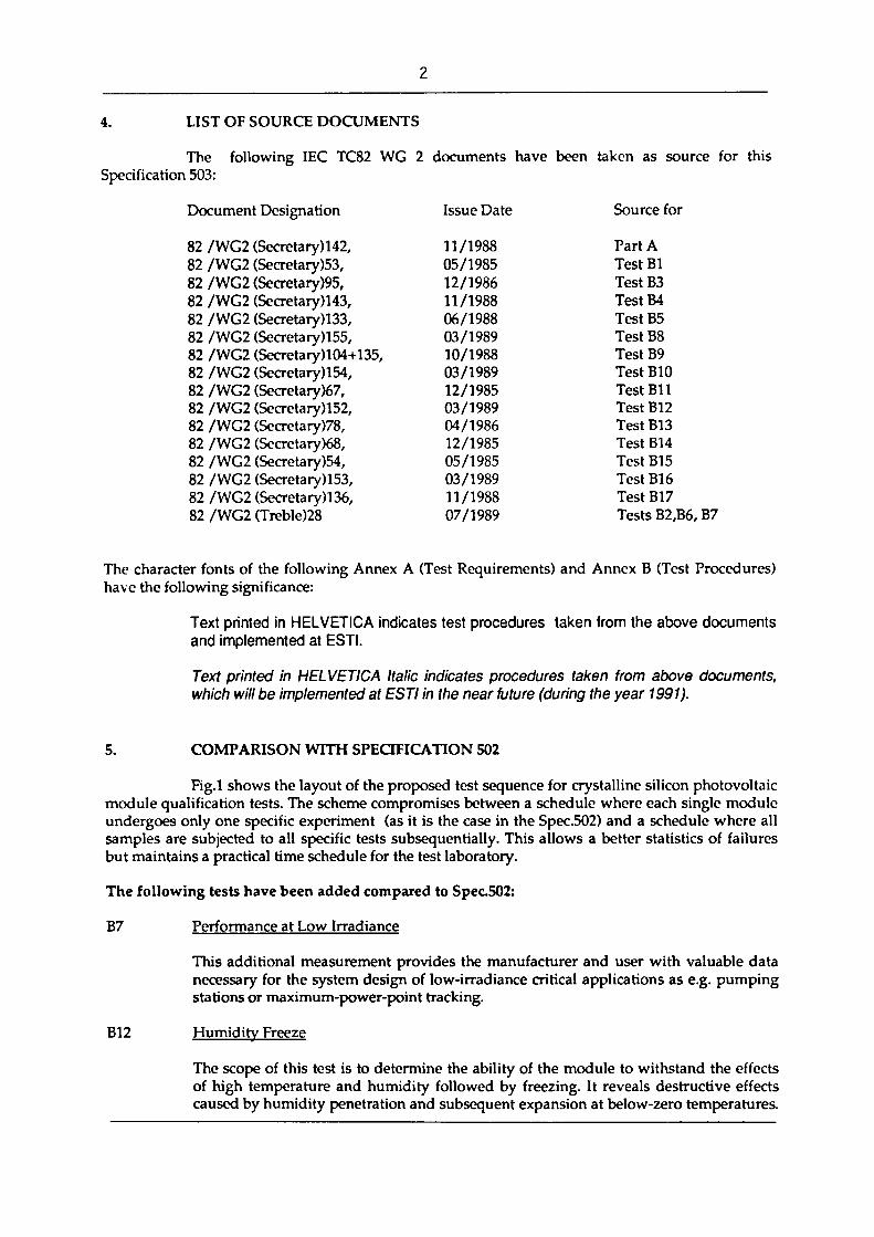
This standard lays down requirements for the design qualification and type approval of terrestrial photovoltaic modules suitable for long-term operation in general open-air climates, as defined in IEC 721-2-1. It applies only to crystalline silicon types. Standards for thin-film modules and other environments, such as marine or equatorial conditions, are under consideration.
IEC publications quoted in this standard are:
IEC 68-1 Basic environmental testing procedures. Part 1: General.
IEC 68-2-3 Basic environmental testing procedures. Part 2: Tests.
IEC 68-2-21 Basic environmental testing procedures. Part 2: Tests. Test U: Robustness of terminations and integral mounting devices.
IEC 721-2-1 Classification of environmental conditions: Part II Environmental conditions appearing in nature, temperature and humidity.
IEC 891 Procedures for temperature and irradiance corrections to measured l-V characteristics of crystalline silicon photovoltaic (PV) devices.
IEC 904-1 Measurement of photovoltaic current-voltage characteristics.
IEC 904-3 Measurement principles for terrestrial photovoltaic solar devices, with reference spectral irradiance data.
A2 PURPOSE
To determine the electrical and thermal characteristics of the module and to show, as far as is possible within reasonable constraints of cost and time, that the module is capable of withstanding prolonged exposure in the climates described in the Introduction. The actual lifetime expectancy of modules so qualified will depend on their design, their environment and the conditions under which they are operated.
A3 SAMPLING
Eight modules for qualification testing (plus spares as desired) shall be taken at random from a production batch or batches. The modules shall have been manufactured from specified materials and components in accordance with the relevant drawings and process sheets and have been subjected to the manufacturer's normal inspection, quality control and production acceptance procedures. The modules shall be complete in every detail and shall be accompanied by the manufacturer's handling, mounting and connection instructions, including the maximum permissible system voltage.
When the modules to be tested are prototypes of a new design and not from production, this fact shall be noted in the test report (see Clause A8).

A4 MARKING
Each module shall carry the following clear indelible markings:
name, monogram or symbol of manufacturer; type or model number; serial number; polarity of terminals or leads (colour coding is permissible); maximum system voltage for which the module is suitable.
The date and place of manufacture shall be marked on the module or be traceable from the serial number.
A5 TESTING
The modules shall be divided into groups and subjected to the test sequences in Fig.1, carried out in the order laid down. Test procedures and severities, including initial and final measurements where necessary, are detailed in Part B.
In carrying out the tests, the tester shall strictly observe the manufacturer's handling, mounting and connection instructions. Test B4 may be omitted if the temperature coefficients a and
B are already known.
Test levels are summarised in Table I.
A6 PASS CRITERIA
A module design shall be judged to have passed the qualification tests, if each test sample meets all the following criteria:
a) The degradation of maximum output power at STC does not exceed the prescribed limit after each test nor 8% after each test sequence.
b) No sample has exhibited any open-circuit or ground fault during the tests.
c) There is no visual evidence of a major defect, as defined in Clause A7.
d) The insulation test requirements are met after the tests.
If two or more modules do not meet these test criteria, the design shall be deemed not to have met the qualification requirements. Should one module fail any test, another two modules meeting the requirements of Clause A3 shall be subjected to the whole of the relevant test sequence from the beginning. If one or both of these modules also fail, the design shall be deemed not to have met the qualification requirements. If, however, both modules pass the test sequence, the design shall be judged to have met the qualification requirements.

A7 MAJOR VISUAL DEFECTS
For the purposes of design qualification and type approval, the following are considered to be major visual defects:
1) broken or cracked wi ndow;
2) a crack in a cell whose propagation could remove more than 10% of that cell's area from the electrical circuit of the module;
3) bubbles or delamination forming a continuous path between any part of the electrical circuit and the edge of the module;
4) loss of mechanical integrity, to the extent that the installation and/or operation of the module would be impaired.
A8 REPORT
A certified report of the qualification tests, with measured performance characteristics and details of any failures and re-tests, shall be prepared by the test agency. A copy of this report shall be kept by the manufacturer for reference purposes.
A9 MODIFICATIONS
Any change in the design, materials, components or processing of the module may require a repetition of some or all of the qualification tests to maintain type approval.

Test No. Title Test level
B1
B2
B3
B4
B5
B6
B7
Visual Inspection
Performance at STC
Insulation
See detailed inspection list in B1.2
Cell temp. : 25*C Irradiance : 1000 W-rrv2 with IEC 904-3 reference solar spectral irradiance distribution
1000 Vdc + twice the open-circuit voltage of the system at STC for 1min. Insulation resistance not less than 50 Megohms at 500 Vdc.
Measurement of Temperature Coeff. See detail in B4
Measurement ofNOCT
Performance at NOCT
Performance at Low Irradiance
B8
B9
B10
B11
B12
B13
B14
B15
B16
B17
Outdoor Exposure
Hot Spot Endurance
UV Exposure
Thermal Cycling
Humidity Freeze
Damp Heat
Robustness of Terminations
Twist
Mechanics' Load
Hail Resistance
Total solar irradiance :800 W-m2
Ambient temperature : 20 'C Wind Speed : 1 ms1
Cell temp. : NOCT. Irradiance : 800 Wrrr2 with IEC 904-3 reference solar spectral irrradiance distribution
Cell temp. :25'C Irradiance : 200 W-rrr* with IEC 904-3 reference solar spectral irrradiance distribution
60 kWh-m2 total solar irradiation
Five 1 hour exposures to 1000 W-nr2 irradiance in worst-case hot-spot condition.
15 kWh-m2 UV irradiation
50 and 200 cycles from -40*C to +85*C.
10 cycles from +85'C, 85% RH to -40'C.
1000 hours at +85*C, 85% RH.
As in IEC 68-2-21.
Deformation Angle: 1.2*.
2 cycles of 2400 Pa uniform load, applied for 1 hour to front and back surfaces in turn.
25 mm diam. ice ball at 23.0 m s \ directed at 11 impact locations.
Table I SUMMARY OF TEST LEVELS

8 modules
B1 VISUAL
INSPECTION
B2 PERFORMANCE
ATSTC
B3 INSULATION
TEST
B4 MEASURE TEMP COEFnCIENTS
B10 UVTEST
B11 THERMAL CYCUNG
200 cycles B13
DAMP HEAT
B11 THERMAL CYCLING
50 cycles
C o o
B6 PERFORMANCE
AT NOCT
B12 HUMIDITY FREEZE
B7 PERFORMANCE Al LOW IRRADIANCE
B8 OUTDOOR EXPOSURE
REPEAT B1. B2 & B3 AS REQUIRED
B9 HOT SPOT
ENDURANCE
B16 MECHANICAL
LOAD B17
HAIL TEST
BU ROBUSTNESS OF TERMINATIONS
Fig.1 QUALIFICATION TEST SEQUENCE


11
PART B: TEST PROCEDURES
B1 VISUAL INSPECTION
B1.1 Purpose
To detect any visual defects in the module.
B1.2 Procedure
Carefully inspect each module under an illumination of not less than 1000 lux for the following conditions:
broken, cracked or torn external surfaces; broken cells; cracked cells; faulty interconnections or joints; cells touching one another or the frame; failure of adhesive bonds; bubbles or delamination forming a continuous path between a cell and the edge of the module; tacky surfaces of plastic materials; faulty terminations; any other conditions which may affect performance.
Make note of and/or photograph the nature and position of any cracks, bubbles or delamination, etc., which may worsen and adversely affect the module performance in subsequent tests.
B1.3 Requirement
Visual conditions other than the major visual defects listed in Clause A7 are acceptable for the purposes of type approval.
12
B2 PERFORMANCE AT STC
B2.1 Purpose
To determine how the electrical performance of the module varies with load at Standard Test Conditions (cell temperature: 25±2'C, irradiance: 1000 W-rrr2, with the IEC 904-3 reference solar spectral irradiance distribution).
B2.2 Procedure
Determine the current-voltage characteristic of the module at STC, in accordance with IEC 904-1, using natural sunlight or a Class A simulator conforming to the requirements of the relevant IEC publication. When necessary, make temperature and irradiance corrections in accordance with IEC 891.

13
B3 INSULATION
B3.1 Purpose
To determine whether or not the module is sufficiently well insulated.
B3.2 Test conditions
The test shall be made on modules at ambient temperature of the surrounding atmosphere (see IEC 68-1) and in a relative humidity not exceeding 75%.
B3.3 Procedure
1) Connect the shorted output terminals of the module to the positive terminal of a D.C. insulation tester with a current limitation.
2) Connect the exposed metal parts of the module to the negative terminal of the tester. If the module has no frame or if the frame is a poor electrical conductor, mount the module on a metallic simulated support structure, which is to be connected to the negative terminal of the tester.
3) Increase the voltage applied by the tester at a rate not exceeding 500 Vs"1 to a maximum equal to 1000 V plus twice the maximum system voltage (i.e. the open-circuit voltage of the system at STC). Maintain the voltage at this level for 1 minute. If the maximum system voltage does not exceed 50V, the applied voltage shall be 500 V.
4) Reduce the applied voltage to zero and short-circuit the terminals of the tester for 5 minutes, while still connected to the module.
5) Remove the short-circuit.
6) Apply a D.C. voltage of not less than 500 V to the module, with the tester connected as in Steps 1 and 2. Determine the insulation resistance.
B3.4 Requirements
No dielectric breakdown or surface tracking during Step 3. Insulation resistance not less than 50 megohms.

14
B4 MEASUREMENT OF TEMPERATURE COEFFICIENTS
B4.1 Purpose
To determine the temperature coefficients of current (a) and voltage (B) from
module measurements. The coefficients so determined are valid at the irradiance at which the measurements were made. For linear modules, they are also valid over an irradiance range of ±30% of this level. This procedure supplements that in IEC 891 for measuring these coefficients from a representative set of single cells.
B4.2 Apparatus
1) Solar simulator (Class B or better), conforming to IEC publication (under consideration). Means to measure irradiance, short-circuit current and open-circuit voltage in accordance with IEC 904-1, Clause 2.
B4.
Note: The use of a pulsed simulator is preferred, since it creates little additional heat that could affect the module during the measurement. If a steady-state simulator is used, it should be equipped with a shutter or equivalent means to minimise the period irradiance to 0.5 seconds or less.
2) Means to measure the surface or cell temperature of the module to an accuracy of ±0.5*C.
3) A chamber capable of accommodating the module, equipped with a transparent window and means for evenly heating and cooling the contents over the temperature range of interest.
Procedure
1) Determine the short-circuit current of the module at the desired irradiance at room temperature, in accordance with IEC 904-1.
2) Mount the test module in the chamber and a suitable irradiance monitor outside the chamber within the simulator beam. Connect to the instrumentation.
3) Close the chamber and set the irradiance so that the test module produces the short-circuit current determined in Step 1. Use the irradiance monitor to maintain this irradiance setting throughout the test.
4) Heat the module to the maximum temperature of interest, switch off the heater and allow the module to cool evenly.
5) As the module cools, take measurements of the short-circuit current and open-circuit voltage at 5"C intervals over a range of interest of at least 30*C.
Note: The complete current-voltage characteristic may be measured at each temperature to determine the curve correction factor K, in accordance with IEC 891, Clause 5.
15
6) Plot the values of l s c and V ^ as functions of temperature and construct a least-squares fit curve through each set of data.
7) From the slopes of the current and voltage curves at a point midway between the minimum and maximum temperatures of interest, calculate a and 6, the temperature coefficients for the module.

16
B5 MEASUREMENT OF THE NOMINAL OPERATING CELL TEMPERATURE
(NOCT)
B5.1 Purpose
To determine the NOCT of the module.
B5.2 Introduction NOCT is defined as the equilibrium mean solar cell junction temperature within
an open rack mounted module in the following Standard Reference Environment:
- tilt angle: at normal incidence to the direct solar beam at local solar noon; - totalirradiance: BOO Wm'2; - ambient temperature: 20'C; - wind speed: 1 ms'1; - electrical load: nil (open circuit).
NOCT can be used by the system designer as a guide to the temperature at which a module will operate in the field and it is therefore a useful parameter when comparing the performance of different module designs. However, the actual operating temperature at any particular time is affected by the mounting structure, irradiance, wind speed, ambient temperature, sky temperature and reflections and emissions from the ground and nearby objects. For accurate performance predictions, these factors should be taken into account.
B5.3 Method
B5.3.1 Principle
This method is based on gathering actual measured cell temperature data under a range of environmental conditions including the Standard Reference Environment. The data are presented in a way that allows accurate and repeatable interpolation of the NOCT.
The temperature of the solar cell junction (TJ is primarily a function of the ambient temperature (Tamb), the average wind speed (V) and the total solar irradiance (E) incident on the active surface of the module. The temperature difference (Tj-Tamb) is largely independent of the ambient temperature and is essentially linearly proportional to the irradiance at levels above 400 Wnr2. The procedure calls for plotting (Tj-T^ against E for a period when wind conditions are favourable. A preliminary NOCT value is then determined by adding 20'C to the value of (TJ-T^J,^ interpolated at the Standard Reference Environment irradiance of 800 Wnr2. Finally, a correction factor, dependent on the average temperature and wind speed during the test period, is added to the preliminary NOCT to correct it to 20 'C and 1ms1
B5.3.2 Apparatus
The following apparatus is required:
1) An open rack to support the test module(s) and pyranometer in the specified manner (see Clause B5.3.3). The rack shall be designed to minimise heat conduction from the modules and to interfere as little as possible with the free radiation of heat from their front and back surfaces. Note: In the case of modules not designed for open rack mounting, the test module(s) shall be mounted as recommended by the manufacturer.

17
2)
3)
4)
5)
6)
A pyranometer, mounted in the plane of the module(s) and within 0.3 m of the test array.
Instruments to measure wind speed down to 0.25 ms'1 and wind direction, installed approximately 0.7 m above the top of the module(s) and 1.2 m to the East or West.
An ambient temperature sensor, with a time constant approaching that of the module(s), installed in a shaded enclosure with good ventilation near the wind sensors.
Cell temperature sensors, attached by solder or thermally-conductive adhesive to the backs of two solar cells near the middle of each test module, or other equipment necessary for IEC-approved measurement of cell temperature.
A data acquisition system to record the following parameters within an interval of no more than 60 s:
Parameter
Irradiance Ambient temperature Cell temperature Wind speed Wind direction
Accuracy:
± 5 Wrrr2
± 0.5'C ± 0.5'C ± 0.5ms1
±10'
B5.3.3 Test module mounting
Tilt angle. The test module(s) shall be positioned so that it is normal to the direct solar beam (within ± 5') at local solar noon.
Height. The bottom edge of the test module(s) shall be 0.6 m or more above the local horizontal plane or ground level.
Configuration. To simulate the thermal boundary conditions of modules installed in an array, the test module(s) shall be mounted in the interior of a planar surface that extends at least 0.6 m beyond the module(s) in all directions. For modules designed for free-standing, open-back installations, black aluminium plates or other modules of the same design shall be used to fill out the remaining open area of the planar surface.
Surrounding area. There shall be no obstructions to prevent full irradiance of the test module(s) during the period from 4 hours before local solar noon to 4 hours after local solar noon. The ground surrounding the module(s) shall not have an abnormally high solar reflectance and shall be flat and level or sloping away from the test fixture in all directions. Grass, other types of vegetation, black asphalt or dirt are acceptable for the local surrounding area.
B5.3.4 Procedure
1) Set up the apparatus with the test module(s), as described in Clause B5.3.3. Ensure that the test module(s) are open circuited.
18
2)
3)
On a suitable clear sunny day with little wind, record, as a function of time, the cell temperature, the ambient temperature, the irradiance, wind speed and wind direction.
Reject all data taken during the following conditions:
- irradiance below 400 Wnr2;
• wind speeds outside the range 1 + 0.75 m·s-1;
- ambient temperatures outside the range 20 + 15'C or varying by more than 5'C; -a 10 minute interval after a wind gust of more than 4m·s
-1;
- wind direction within + 20' of East or West.
4)
5)
6)
7)
8)
From a minimum of 10 acceptable data points covering an irradiance range of at least 300 Wmr
2, plot (TjTamb)
as a function of irradiance. Draw a straight line through the points.
From the straight line, determine the value of (Tj-Tamb) at 800 W·m-
2 and add 20°C to give the preliminary value ofNOCT.
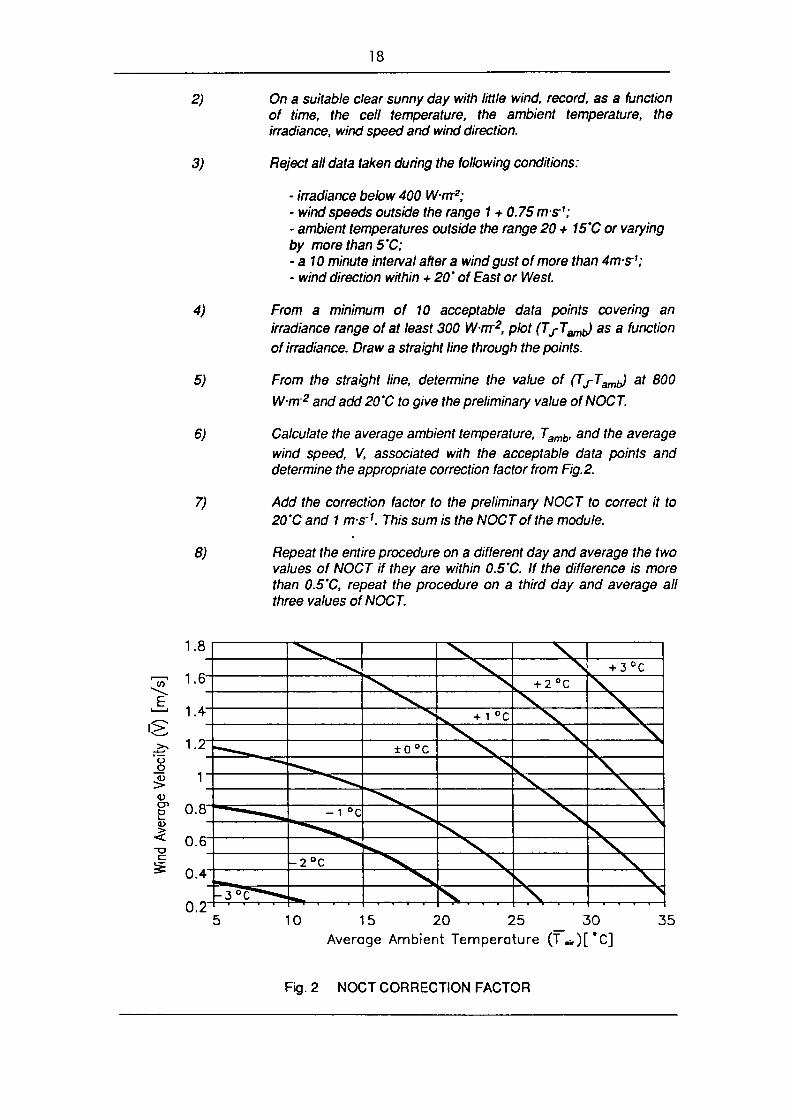
Calculate the average ambient temperature, Tamb, and the average wind speed, V, associated with the acceptable data points and determine the appropriate correction factor from Fig. 2.
Add the correction factor to the preliminary NOCT to correct it to 20'C and 1 ms
1. This sum is the NOCT of the module.
Repeat the entire procedure on a different day and average the two values of NOCT if they are within 0.5'C. If the difference is more than 0.5'C, repeat the procedure on a third day and average all three values ofNOCT.
t/3
E 1 ' <> _>> o o £ E
i.a
1.6-
1.4
1.2"
1
0.8"
0.6T
0.4 - 3 ° C * - - * « ,
I I ■ 1 1
- 1 °C
- 2 ° C
^ 1 ■■ 1
± o ° c
f . . . , - T ■ t .
^ +1 °c
. + 2 ° C + 3°C
10 15 20 25 _ 30 Average Ambient Temperature (Ta i r)[*C]
35
Fig. 2 NOCT CORRECTION FACTOR
19
B6 PERFORMANCE A T NOCT
B6.1 Purpose
To determine how the electrical performance of the module varies with bad at NOCT and an irradiance of 800 Wrrr2, with the IEC 904-3 reference solar spectral irradiance distribution.
B6.2 Procedure
Heat the module unifonnly to NOCT and trace its current-voltage characteristic at an irradiance of 800 Wrrr2 (as measured by a suitable reference device), in accordance with IEC 904-1, using natural sunlight or a Class A simulator conforming to the requirements of the relevant IEC publication.
Alternatively, transpose the l-V characteristic measured at room temperature and 800 W.mr2 to NOCT in accordance with IEC 891.
B7 PERFORMANCE AT LOW IRRADIANCE
B7.1 Purpose
To determine how the electrical performance of the module varies with load at 25'C and an irradiance of 200 Wrrr2, with the IEC 904-3 reference solar spectral irradiance distribution.
B7.2 Procedure
Determine the current-voltage characteristic of the module at 25 ± 2'C and an irradiance of 200 Wrrr2 (as measured by a suitable reference device), in accordance with IEC 904-1, using natural sunlight or a Class A simulator conforming to the requirements of the relevant IEC publication. The irradiance shall be reduced to the specified level by using neutral filters or other technique which does not affect the spectral irradiance distribution.
When necessary, make temperature and irradiance corrections in accordance with IEC 891.

20
B8
B8.1
OUTDOOR EXPOSURE
Purpose
To make a preliminary exposure to outdoor conditions anc not be detected by laboratory tests.
assessment of the ability of the module to withstand reveal any synergistic degradation effects which may
B8.2
B8.3
B8.4
B8.5
Apparatus
1) A solar irradiation monitor, accurate to ± 10%.
2)
Procedure
1)
2)
Means to mount the module, as recommended by the manufacturer, co-planar with the irradiation monitor.
Short-circuit the module and mount it outdoors, as recommended by the manufacturer, co-planar with the irradiation monitor. Any hot spot protective devices recommended by the manufacturer shall be installed before the module is tested.
Subject the module to an irradiation totalling 60 kWhnrr2, as measured by the monitor, under conditions conforming to general open-air climates, as defined in I EC 721-2-1.
Final measurements
Repeat Tests B1, B2 and B3.
Requirements
not No evidence of major visual defects, as defined in Clause A7. The degradation of maximum output power at STC shall exceed 5% of the value measured before this test. Insulation resistance shall meet the same requirements as for the initial measurements.
21
B9 HOT SPOT ENDURANCE
B9.1 Purpose
To determine the ability of the module to withstand hot spot heating effects, e.g. solder melting or deterioration of the encapsulation. This defect could be provoked by cracked or mismatched cells, interconnect failures, partial shadowing or soiling.
B9.2 Hot spot effect
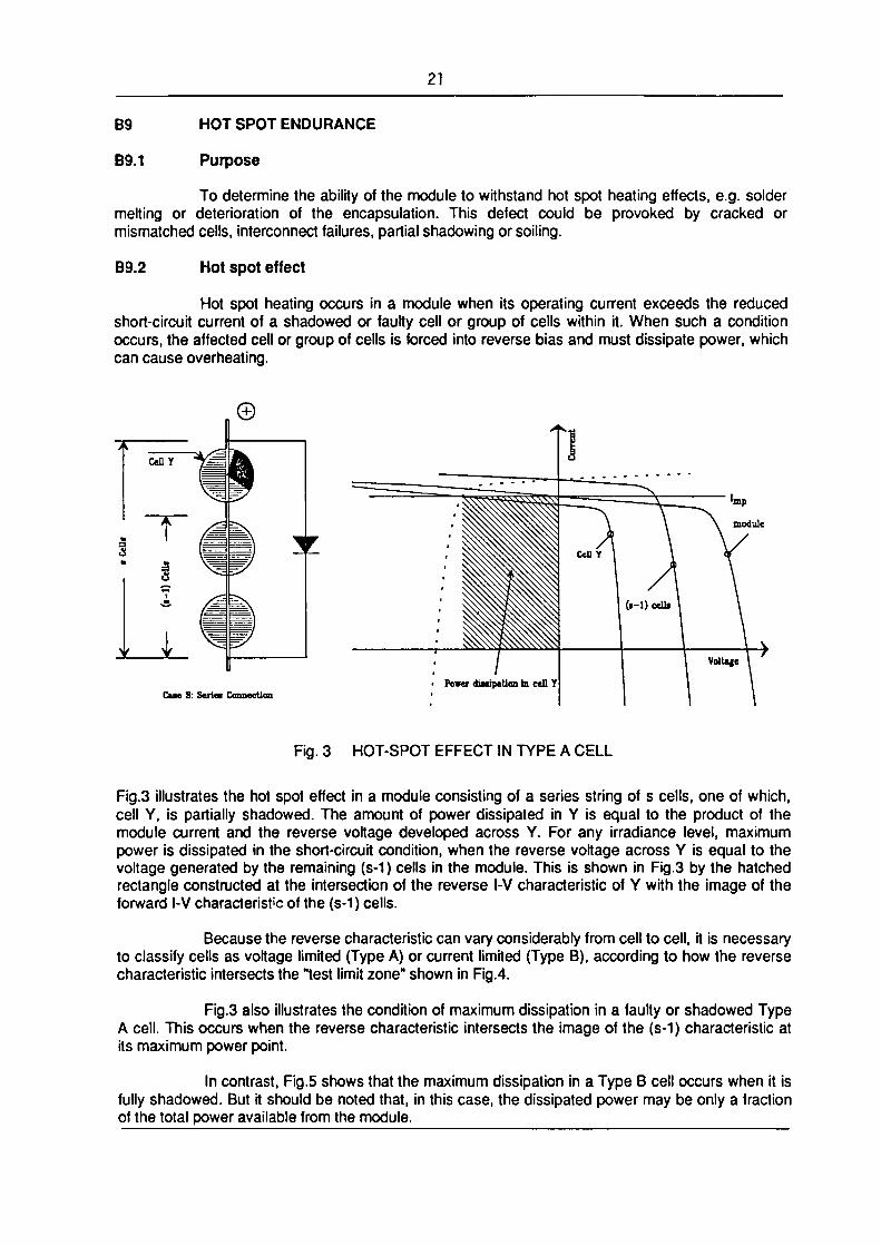
Hot spot heating occurs in a module when its operating current exceeds the reduced short-circuit current of a shadowed or faulty cell or group of cells within it. When such a condition occurs, the affected cell or group of cells is forced into reverse bias and must dissipate power, which can cause overheating.
module
Cue S: Serlee Connection
Fig. 3 HOT-SPOT EFFECT IN TYPE A CELL
Fig.3 illustrates the hot spot effect in a module consisting of a series string of s cells, one of which, cell Y, is partially shadowed. The amount of power dissipated in Y is equal to the product of the module current and the reverse voltage developed across Y. For any irradiance level, maximum power is dissipated in the short-circuit condition, when the reverse voltage across Y is equal to the voltage generated by the remaining (s-1) cells in the module. This is shown in Fig.3 by the hatched rectangle constructed at the intersection of the reverse l-V characteristic of Y with the image of the forward l-V characteristic of the (s-1) cells.
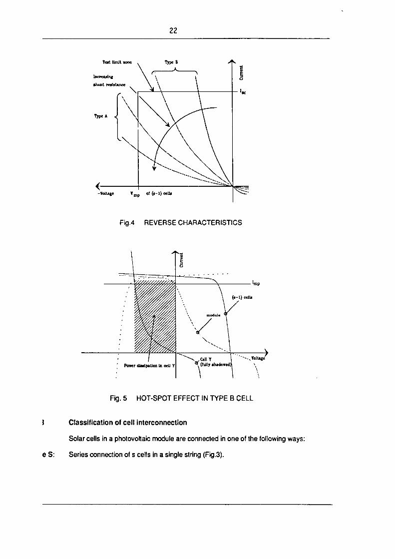
Because the reverse characteristic can vary considerably from cell to cell, it is necessary to classify cells as voltage limited (Type A) or current limited (Type B), according to how the reverse characteristic intersects the "test limit zone" shown in Fig.4.
Fig.3 also illustrates the condition of maximum dissipation in a faulty or shadowed Type A cell. This occurs when the reverse characteristic intersects the image of the (s-1) characteristic at its maximum power point.
In contrast, Fig.5 shows that the maximum dissipation in a Type B cell occurs when it is fully shadowed. But it should be noted that, in this case, the dissipated power may be only a fraction of the total power available from the module.
22
Teat limit wne
Increulnf
■hunt reaiaUnce
Type A .<
-Voltaje ¥ m . of (f-1) cella
Fig.4 REVERSE CHARACTERISTICS
. \/////////////.M\ ^V 'mp
(■-1) cell!
V
Power diaripation In cell Y v^CellY I
<? (lullj ahadovedjj ..Volt^c
Fig. 5 HOT-SPOT EFFECT IN TYPE B CELL
J Classification of cell interconnection
Solar cells in a photovoltaic module are connected in one of the following ways:
e S: Series connection of s cells in a single string (Fig.3).

23
I Fig.6 CASE SP : SERIES-PARALLEL CONNECTION
1 2
W-..<>
6 6 6 e
Fig. 7 CASE SPS : SERIES-PARALLEL-SERIES CONNECTION
Case SP: Series-parallel connection, i.e. a parallel connection of p strings, each with s cells in series (Fig.6).
Case SPS: Series-parallel-series connection, i.e.. a series connection of b blocks, where each block consists of a parallel connection of p strings, each with s cells in series (Fig.7).
By-pass diodes, if present, limit the reverse voltage of the enclosed cells and therefore define the part of the circuit to be tested. Each configuration requires a particular hot spot testing procedure. The maximum internal power dissipation occurs with the module short-circuited.

24
B9.4 Apparatus
1) Radiant source 1. Steady-state solar simulator or natural sunligyht capable of an irradiance of not less than 700 W-nr2 with a non-uniformity not more than ± 2% and a temporal stability within ± 5%.
2) Radiant source 2. Class C steady-state solar simulator (or better) or natural sunlight with an irradiance of 1000 W-nr2 ± 10%.
3) Module l-V curve tracer.
4) Set of opaque covers for test cell shadowing in 5% increments.
5) An appropriate temperature detector, if required.
B9.5 Procedures
All tests shall be performed at an ambient temperature of 25 ± 5"C, with a wind speed less than 2 ms"1. Any hot spot protective devices recommended by the manufacturer shall be installed before the module is tested.
B9.5.1 Case S
1) Expose the unshadowed module to Radiant Source 1 at an irradiance of not less than 700 W-nr2. Measure the l-V characteristic and determine the current at maximum power, l ^ .
2) Short-circuit the module and select a cell by one of the following methods:
a) With the module exposed to Radiant Source 1 at a stable irradiance of not less than 700 W-nr2, determine the hottest cell using an appropriate temperature detector.
b) Under the irradiance specified for Step 1, completely shadow each cell in turn and select the cell or one of the cells which gives the biggest decrease in short-circuit current when shadowed. During this process, the irradiance shall not change by more than ± 5%.
3) Under the same irradiance (within ± 3%) as used in Step 1, completely shadow the selected cell and check that the lte of the module is less than the l^ , as determined in Step 1. If this condition does not occur, one cannot set the condition of maximum power dissipation within a single cell. In this case, proceed with the selected cell completely shadowed, omitting Step 4.
4) Gradually decrease the shadowed area of the selected cell until the l,c of the module coincides as closely as possible with l ^ . In this condition, the maximum power is dissipated within the selected cell.
5) Expose the module to Radiant Source 2. Note the value of l,c and keep the module in the condition of maximum power dissipation, re-adjusting the shadow, if necessary, to maintain the ltc at the specified level.
6) After 1 hour, shade the module from the light source and verify that I1C is not more than 10% of I .
mp

25
7) After 30 minutes, restore the irradiance to 1000 W-rrr2.
8) Repeat Steps 5, 6 and 7 a total of five times.
B9.5.2 Case SP
1) Expose the unshadowed module to Radiant Source 1 at an irradiance of not less than 700 W-rrr2. Measure the l-V characteristic and determine llc(*), the short-circuit current corresponding to the condition of maximum hot spot power dissipation, from the following equation, assuming that all strings generate the same current:
BC)-I«-(P-1)/P + Imp/P
where: l s c is the short-circuit current of the unshadowed module;
lmp is the current at maximum power of the unshadowed module;
P is the number of paralleled strings in the module.
2) Short-circuit the module and select a cell by one of the following methods:
a) With the module exposed to Radiant Source 1 at a stable irradiance of not less than 700 W-rrr2, determine the hottest cell using an appropriate temperature detector.
b) Under the irradiance specified in Step 1, completely shadow each cell in turn and find the cell which gives the biggest decrease in short-circuit current when shadowed. During this process, the irradiance shall not change by more than ± 5%.
3) Under the same irradiance as in Step 1 (within ± 3%), check that, with the selected cell fully shadowed, the l,c of the module is less than ltc(*), as determined in Step 1. If this condition does not occur, one cannot set the condition of maximum power dissipation within a single cell. In this case, proceed with the selected cell fully shadowed, omitting Step 4.
4) Gradually decrease the shadowed area of the selected cell until the l,c of the module coincides as closely as possible with ltc(*). In this condition, the maximum power is dissipated within the selected cell.
5) Expose the module to Radiant Source 2. Note the value of \K and keep the module in the condition of maximum power dissipation, re-adjusting the shadow, if necessary, to maintain the l,c at the specified level.
6) After 1 hour, shade the module from the light source and verify that the l,c
is not more than 10% of lm .
7) After 30 minutes, restore the irradiance to 1000 W-rrr2.
8) Repeat Steps 5,6 and 7 a total of five times.

26
B9.5.3 CaseSPS
1) Short-circuit the unshadowed module and expose it to Radiant Source 1 at a stable irradiance of not less than 700 W-rrr2. Take at random at least 30% of the cells in the module, fully shadow each cell in turn and measure the temperature at which it stabilises, using thermal imaging equipment or other appropriate means.
2) Fully shadow the hottest cell found in Step 1.
3) While continuing to monitor its temperature, gradually decrease the shadowed area and determine the condition in which maximum temperature is achieved.
4) Expose the module to Radiant Source 2 and keep it in the shadowed condition established in Step 3.
5) After 1 hour, shade the module from the light source.
6) After 30 minutes, restore the irradiance to 1000 W-nr2.
7) Repeat Steps 4,5 and 6 a total of five times.
B9.6 Final measurements
Repeat Tests B1, B2 and B3.
B9.7 Requirements
No evidence of major visual defects, as defined in Clause A7. The degradation of maximum output power at STC shall not exceed 5% of the value measured before this test. Insulation resistance shall meet the same requirements as for the initial measurements.

27
B10 UV EXPOSURE
B10.1 Purpose
To determine the ability of the module to withstand exposure to ultra-violet (UV) radiation.
B10.2 Apparatus
1) A radiant source, capable of subjecting the module to UV radiation between 280 and 400 nm at an irradiance not exceeding 250 W m2 (i.e. about five times the natural sunlight level) and with an irradiation uniformity of ± 15% over the test plane. The module shall be protected from any ozone produced.
2) Means to keep the module temperature at 60 ± 5*C and to monitor this temperature to an accuracy of ± 2"C.
3) A UV monitor, sensitive only to radiation between 280 and 400 nm, to measure the irradiation.
B10.3 Procedure
1) Mount the module in the test plane co-planar with the UV monitor.
2) Subject the module to a total UV irradiation of 15 kWhm2, as measured by the monitor, maintaining the module temperature within the prescribed range.
Note: The indicated UV irradiation corresponds to 325 hours
exposure in the IEC 904-3 reference solar irradiance.
B10.4 Final measurements
Repeat Tests B1, B2 and B3.
B10.5 Requirements
No evidence of major visual defects, as defined in Clause A7. The degradation of maximum output power at STC shall not exceed 5% of the value measured before this test. Insulation resistance shall meet the same requirements as for the initial measurements.

28
B11 THERMAL CYCLING
B11.1 Purpose
To determine the ability of the module to withstand thermal mismatch, fatigue and other stresses caused by repeated changes of temperature.
B11.2 Apparatus
1)
2)
3)
B11.3
4)
5)
Procedure
1)
2)
3)
A climatic chamber with automatic temperature control, means for circulating the air inside and means to avoid condensation on the module during the test, capable of subjecting one or more modules to the thermal cycle in Fig.8.
Means for mounting or supporting the module(s) in the chamber, so as to allow free circulation of the surrounding air. The thermal conduction of the mount or support shall be low, so that, for practical purposes, the module(s) are thermally isolated.
Means for measuring and recording the temperature of the module(s) to an accuracy of ± 1"C. The temperature sensors shall be attached to the front or back surface of the module near the middle. If more than one module are tested simultaneously, it will suffice to monitor the temperature of one representative sample.
Means for monitoring, throughout the test, the continuity of the internal circuit of each module.
Instrumentation for monitoring in each module the integrity of the insulation between one of the terminals and the module frame or supporting structure.
4)
Install the module(s) at room temperature in the chamber. If the frame is a poor electrical conductor, mount the module on a metal frame simulating an open support structure.
Connect the temperature monitoring equipment to the temperature sensor(s). Connect the continuity instrumentation across the module terminals. Connect the insulation monitor between one terminal and the frame or supporting structure.
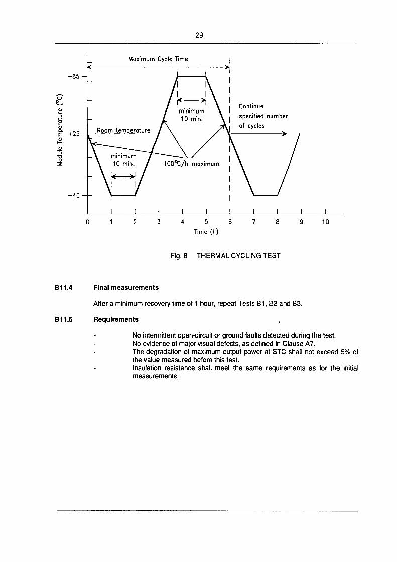
Close the chamber and, with the air around the module(s) circulating at a velocity of not less than 2 m.s"1, subject the module(s) to cycling between module temperatures of -40 ± 2'C and +85 ± 2'C, in accordance with the profile in Fig.8. The rate of change of temperature between the low and high extremes shall not exceed 100*C/hour and the module temperature shall remain stable at each extreme for a period of at least 10 minutes. The cycle time shall not exceed 6 hours. The number of cycles shall be as shown in the relevant blocks in Fig.1.
Throughout the test, record the module temperature and monitor the module(s) to detect any open-circuit or ground faults that may occur during the exposure.
29
Maximum Cycle Time
+85 -
o o
0J k_ 3 "5
<D Q . E
t— JU
O
+25
Continue specified number of cycles
4 5 6 Time (h)
10
Fig. 8 THERMAL CYCLING TEST
B11.4 Final measurements
After a minimum recovery time of 1 hour, repeat Tests B1, B2 and B3.
B11.5 Requirements
No intermittent open-circuit or ground faults detected during the test. No evidence of major visual defects, as defined in Clause A7. The degradation of maximum output power at STC shall not exceed 5% of the value measured before this test. Insulation resistance shall meet the same requirements as for the initial measurements.
30
B12 HUMIDITY FREEZE
B12.1 Purpose
To determine the ability of the module to withstand the effects of high temperature and humidity followed by sub-zero temperatures. This is not a thermal shock test.
B12.2
B12.2.1
Method
Apparatus
B12.2.2
1)
2)
3)
4)
Procedure
D
2)
3)
4)
5)
A climatic chamber with automatic temperature and humidity control, capable of subjecting one or more modules to the humidity freeze cycle specified in Fig.9. At sub-zero temperatures, the dewpoint of the chamber air shall be the chamber temperature.
Means for measuring and recording the module temperature to an accuracy of ± 1"C (if more than one module are tested simultaneously, it will suffice to monitor the temperature of one representative sample).
Means for monitoring, throughout the test, the continuity of the internal circuit of each module.
Instrumentation for monitoring in each module the integrity of the insulation between one of the terminals and the module frame or supporting structure.
Attach a suitable temperature sensor to the front or back surface of the module(s) near the middle.
Install the module(s) at room temperature in the climatic chamber at an angle of not less than 5* to the horizontal. If the frame is a poor electrical conductor, mount the module on a metal frame simulating an open support structure.
Connect the temperature monitoring equipment to the temperature sensor(s). Connect the continuity instrumentation across the module terminals. Connect the insulation monitor between one terminal and the frame or supporting structure.
After closing the chamber, subject the module(s) to 10 complete cycles in accordance with the profile in Fig.9. The maximum and minimum temperatures shall be within ± 2*C of the specified levels and the relative humidity shall be maintained within ± 5% of the specified value at all temperatures above room temperature.
Throughout the test, record the module temperature and monitor the module(s) to detect any open-circuit or ground faults that may occur during the exposure.

31
85% + / - 5% RH Continue for totol
| | of 10 cycles > No RH control i<
End of Cycle
2 0 0 t / h maximum
— > i i < — 30 min. minimum
|< 20 h min. >|< 4h max >|
Time (h)
Fig. 9 HUMIDITY-FREEZE CYCLE
B12.3 Final measurements
After a recovery time of 2 to 4 hours, repeat Tests B1, B2 and B3.
B12.4 Requirements
No intermittent open-circuit or ground faults detected during the test. No evidence of major visual defects, as defined in Clause A7. The degradation of maximum output power at STC shall not exceed 5% of the value measured before this test. Insulation resistance shall meet the same requirements as for the initial measurements.
32
B13 DAMP HEAT
B13.1 Purpose
To determine the ability of the module to withstand the effects of long-term penetration of humidity.
B13.2 Procedure
The test shall be carried out in accordance with IEC 68-2-3 (1969): Basic Environmental Testing Procedures: Part 2 Tests - Test Ca: Damp heat, steady state, with the following provisions:
1) Preconditioning The module(s), being at room temperature, shall be introduced into the chamber without preconditioning.
2) Severities Test temperature: 85*C ± 2*C Relative humidity: 85% ± 5% Test duration: 1000 hours
3) Recovery
Module(s) shall be submitted to a recovery time between 2 and 4 h.
B13.3 Final measurements
At the end of the recovery time, repeat Tests B1, B2 and B3.
B13.4 Requirements
No evidence of major visual defects, as defined in Clause A7. The degradation of maximum output power at STC shall not exceed 5% of the value measured before this test. Insulation resistance shall meet the same requirements as for the initial measurements.

33
B14 ROBUSTNESS OF TERMINATIONS
B14.1 Purpose
To determine that the terminations and the attachment of the terminations to the body of the module will withstand such stresses as are likely to be applied during normal assembly or handling operations.
B14.2 Types of terminations
Three types of module terminations are considered:
Type A: wire or flying lead; Type B: tags, threaded studs, screws, etc.; Type C: connector.
B14.3 Procedure
B14.3.1 Type A terminations
Tensile test
As described in IEC 68-2-21: Test Ua-|, with the following provisions: preconditioning: 1 hour at standard atmospheric conditions for measurement and test; all terminations shall be tested; tensile force shall never exceed the module weight.
Bending test
As described in IEC 68-2-21: Test Ub, with the following provisions: all terminations shall be tested; method 1 - 1 0 cycles (1 cycle is 1 bend in each opposite direction).
B14.3.2 Type B terminations
Tensile and bending tests
a) For module with exposed terminals, each termination shall be tested as for Type A terminations.
b) If the terminations are enclosed in a protective box, the following procedure shall be applied: A cable of the size and type recommended by the module manufacturer, cut to a suitable length, shall be connected to the terminations inside the box using the manufacturer's recommended procedures. The cable shall be taken through the hole of the cable gland, taking care to utilise any cable clamp arrangement provided. The lid of the box shall be securely replaced. The module shall then be tested as for Type A terminations.

34
Torque test
As described in IEC 68-2-21: Test Ud, with the following provisions:
preconditioning: 1 hour at standard atmospheric conditions for measurement and test; all terminations shall be tested; Severity 1.
The nuts or screws should be capable of being loosened afterwards unless they are specifically designed for permanent attachment.
B14.3.3 Type C terminations
A cable of the size and type recommended by the module manufacturer, cut to a suitable length, shall be connected to the output end of the connector and the tests for Type A terminations shall be carried out.
B14.4 Final measurements
Repeat Tests B1 and B2.
B14.5 Requirements
No evidence of mechanical damage. The degradation of maximum output power at STC shall not exceed 5% of the value measured before this test.
35
B15 TWIST
B15.1 Purpose
To detect detects which might be caused to the module when mounted on an imperfect structure.
B15.2 Procedure
1) Instrument the module so that the electrical continuity of the internal circuit and the insulation resistance of the module can be monitored continuously during the test. The insulation resistance shall be measured as described in Test B3, Clause B3.3, Step 6, except that only one of the module terminals shall be connected to the tester.
2) Maintain three corners of the module in the same plane.
3) Displace the fourth corner from this plane by a distance:
h = 0.021 •[ I_2+W2p
where:
h displacement measured perpendicular to the module diagonal (corresponding to an angle of deformation of 1.2');
L length of the module; W width of the module.
Note: The module shall not be in operation during the test.
B15.3 Final measurements
Repeat Tests B1 and B2.
B15.4 Requirements
No intermittent open-circuit or ground faults detected during the test. No evidence of major visual defects, as defined in Clause A7. The degradation of maximum output power at STC shall not exceed 5% of the value measured before this test.

36
B16 MECHANICAL LOAD
B16.1 Purpose
To determine the ability of the module to withstand wind, snow and ice loads.
B16.2 Procedure
1) Instrument the module so that the electrical continuity of the internal circuit can be monitored continuously during the test.
2) Mount the module on a rigid structure by the method prescribed by the manufacturer (if there are different possibilities, use the worst one, where the distance between the fixing points is maximum).
3) On the front surface, apply gradually a load corresponding to 2400 Pa, spread uniformly (this load may be applied pneumatically or by means of a water-filled bag covering the entire surface. In the latter case, the module must be mounted horizontally). Maintain this load for one hour.
4) Without removing the module from the rigid structure, apply the same procedure on the back surface of the module.
5) Repeat Steps 3 and 4.
Note: 2400 Pa corresponds to a wind pressure of 130 kmh "1 (= 800 Pa) with a safety factor of 3 for gusty winds. If the module is to be qualified to withstand heavy accumulations of snow and ice, the load applied to the front of the module during this test shall be increased from 2400 to 5400 Pa.
B16.3 Final measurements
Repeat Tests B1, B2 and B3.
B16.4 Requirements
No intermittent open-circuit fault detected during the test. No evidence of major visual defects, as defined in Clause A7. The degradation of maximum output power at STC shall not exceed 5% of the value measured before this test. Insulation resistance shall meet the same requirements as for the initial measurements.

37
B17 HAIL RESISTANCE
B17.1 Purpose
To verify that the module is capable of withstanding the impact of hailstones.
B17.2 Apparatus
1) Moulds of suitable material for casting spherical ice balls of the required diameter. The standard diameter shall be 25 mm but any of the other diameters listed in Table II may be specified for special environments.
2) A freezer, controlled at -10'C ± 5*C.
3) A storage container for storing the ice balls at a temperature of -4"C ± 2'C.
4) A launcher capable of propelling an ice ball at the specified velocity, within ± 5%, so as to hit the module within the specified impact location. The path of the ice ball from the launcher to the module may be horizontal, vertical or at any intermediate angle, so long as the test requirements are met.
5) A rigid mount for supporting the test module by the method prescribed by the manufacturer, with the impact surface normal to the path of the projected ice ball.
6) A balance for determining the mass of an ice ball to an accuracy of ± 2%.
7) An instrument for measuring the velocity of the ice ball to an accuracy of ± 2%. The velocity sensor shall be no more than 1 m from the surface of the test module.
As an example, Fig.10 shows in schematic form a suitable apparatus, comprising a horizontal pneumatic launcher, a vertical module mount and a velocity meter which measures electronically the time it takes the ice ball to traverse the distance between two light beams.
B17.3 Procedure
1) Using the moulds and the freezer, make sufficient ice balls of the required size for the test, including some for the preliminary adjustment of the launcher.
2) Examine each one for cracks, size and mass. An acceptable ball shall meet the following criteria:
no cracks visible to the unaided eye; diameter within ± 5% of that reuqired; mass within ± 5% of the appropriate nominal value in Table II.
3) Place the balls in the storage container and leave them there for at least one hour before use.
4) Ensure that all surfaces of the launcher likely to be in contact with the ice balls are near room temperature.
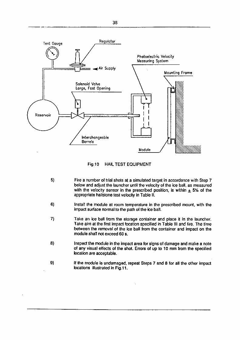
38
Regulator
Photoelectric Velocity Measuring System
Mounting Frame
Module
Fig.10 HAIL TEST EQUIPMENT
5)
6)
7)
8)
9)
Fire a number of trial shots at a simulated target in accordance with Step 7 below and adjust the launcher until the velocity of the ice ball, as measured with the velocity sensor in the prescribed position, is within ± 5% of the appropriate hailstone test velocity in Table II.
Install the module at room temperature in the prescribed mount, with the impact surface normal to the path of the ice ball.
Take an ice ball from the storage container and place it in the launcher. Take aim at the first impact location specified in Table III and fire. The time between the removal of the ice ball from the container and impact on the module shall not exceed 60 s.
Inspect the module in the impact area for signs of damage and make a note of any visual effects of the shot. Errors of up to 10 mm from the specified location are acceptable.
If the module is undamaged, repeat Steps 7 and 8 for all the other impact locations illustrated in Fig.11.

39
B17.4 Final measurements
Repeat Tests B1, B2 and B3.
B17.5 Requirements
No evidence of major visual defects, as defined in Clause A7. The degradation of maximum output power at STC shall not exceed 5% of the value measured before this test. Insulation resistance shall meet the same requirements as for the initial measurements.
Diameter mm
12.5 15 25 35 45 55 65 75
Mass g 0.94 1.63 7.53 20.7 43.9 80.2 132 203
Test velocity m-s-1
16.2 17.7 22.8 27.0 30.7 33.9 36.8 39.6
Table II ICE BALL MASSES AND TEST VELOCITIES
fixing point
Impact Location Shot No.
On the module window, not more than 12mm from one of the points at which the module is fixed to the supporting structure. 1,2
On the module window, at points furthest from the points selected before.
Over points of minimum spacing between cells.
Over edges of cells, near an electrical joint.
3.4
5.6
7.8
An edge of the module, not more than 12mm from the frame. 9
A corner of the module window, not more than 50mm from the frame. 10
Any point which may prove especially vulnerable to hail impact, (e.g. feed-through points of terminals) 11
Fig. 11 IMPACT LOCATIONS ILLUSTRATED


iijijiiiiiriyiniiiiiii III:III liiiiiiii iiiriir,i[ '09ll IU1OO66 426709lHLi10066 426709UH410066 42fi709lW4' 709" "410066 426709'! "410066 426709" II4"