Embed Size (px)
Citation preview

1
PART NO. 212626-000PRINTED IN U.S.A. 0905 SUPERSEDES PART NO. 192011-000 REV.4
MODELS HW-120M, 160M, 200M, 225MCOMMERCIAL GAS COPPER HEAT EXCHANGER WATER HEATER
BURKAY UP-FLOW MODELSIncluding Models with Intermittent Pilot Ignition (I.I.D.)
A DIVISION OF A.O. SMITH CORPORATIONMcBEE, SOUTH CAROLINA, USA
RENTON, WA, USASTRATFORD, ONTARIO, CANADA
VELDHOVEN, THE NETHERLANDSwww.hotwater.com
PLACE THESE INSTRUCTIONS ADJACENT TO HEATERAND NOTIFY OWNER TO KEEP FOR FUTURE REFERENCE
• Installation • Operation • Maintenance • Limited Warranty
WARNING: If the information in theseinstructions are not followed exactly, a fireor explosion may result causing propertydamage, personal injury or death.
—Do not store or use gasoline or otherflammable vapors and liquids in thevicinity of this or any other appliance.
—WHAT TO DO IF YOU SMELL GAS
• Do not try to light any appliance.• Do not touch any electrical switch;
do not use any phone in yourbuilding.
• Immediately call your gas supplierfrom a neighbor’s phone. Followthe gas supplier’s instructions.
• If you cannot reach your gassupplier, call the fire department.
— Installation and service must beperformed by a qualified installer,service agency or the gas supplier.
CAUTIONTEXT PRINTED OR OUTLINED IN RED CONTAINSINFORMATION RELATIVE TO YOUR SAFETY. PLEASE READTHOROUGHLY BEFORE USING APPLIANCE.

2
ROUGH-IN-DIMENSIONS
HEATER PERFORMANCE DATANOTE: To compensate for the effects of high altitude areas above 2000 feet, input rating, and therefore recovery ratings, should bereduced approximately 4% for each 1000 feet above sea level.
Recovery rating of models shown in chart above are obtained by actual efficiency test data by recognized Certification Agency.
NOTE: Recovery rate shown on each models rating plate is based on the requirements of ANSI Standard Z21.10.3, which stipulatesthe data to be based on energy efficiency of 75%.
TABLE 3 - CAPACITY AND GAS AND ELECTRIC CHARACTERISTICS Manifold Pressure Maximum Supply Pressure Electrical Characteristics
Model Type of Gas Inches W.C. kPa Inches W.C. kPa Volts/Hz AmperesHW-120M thru 225M NATURAL 3.5 0.87 10.5 2.61 120/60 <5HW-120M thru 200M PROPANE 10 2.49 13.0 3.23 120/60 <5
Minimum Supply Pressure, Natural Gas: 4.5 inches W.C. (1.12 kPa)Minimum Supply Pressure, Propane Gas: 11.0 inches W.C. (1.74 kPa)Minimum Pressure must be maintained under both load and no load (static and dynamic) conditions.
Models HW-120M HW-160M HW-200M HW-200MDimensions Inches mm Inches mm Inches mm Inches mm
A 49 3/8 1254 50 1/8 1273 53 1/4 1353 60 1524B 30 3/8 772 30 3/8 772 33 1/8 841 33 1/8 841C 23 5/8 600 23 5/8 600 27 1/8 689 27 1/8 689D 20 3/4 527 20 3/4 527 20 3/4 527 20 3/4 527E 5 1/2 140 5 1/2 140 5 1/2 140 5 1/2 140F 10 254 10 254 10 254 10 254G 11 13/16 300 11 13/16 300 11 13/16 300 11 13/16 300H 6 152 7 178 7 178 7 178J 26 11/16 678 26 11/16 678 26 11/16 678 26 11/16 678K 20 3/4 527 20 3/4 527 20 3/4 527 20 3/4 527L 1 1/4 NPT 1 1/4 NPT 1 1/4 NPT 1 1/4 NPTM 1 NPT 1 NPT 1 NPT 1 NPTN 1/2 NPT 1/2 NPT 1/2 NPT 1/2 NPTW 1 3/4 44 1 3/4 44 1 3/4 44 1 3/4 44
Approx.Shipping 120 lbs. 54 Kg. 155 lbs. 70 Kg. 165 Lbs. 75 Kg. 175 lbs. 79 Kg.Weight
TABLE 1 - ROUGH-IN DIMENSIONS
TABLE 2 - RECOVERY CAPACITIESU.S. Gallons/Hrs. and Litres/Hr. at TEMPERATURE RISE INDICATED
Input F° 20F° 30F° 36F° 40F° 50F° 54F° 60F° 70F° 72F° 80F° 90F° 100F° 108F° 110F° 120F° 126F° 130F° 140F°Model Btuh KW C° 11.1C° 16.6C° 20C° 22.2C° 27.7C° 30C° 33.3C° 38.8C° 40C° 44.4° 50C° 55.5C° 60C° 61.1C° 66.6C° 70C° 72.2C° 77.7C°
120,000 GPH 605 403 336 303 242 224 202 173 168 151 134 121 112 110 101 96 93 8635 LPH 2290 1527 1272 1145 916 848 763 654 636 573 509 458 242 416 382 364 352 327
160,000 GPH 777 518 432 388 311 288 259 222 216 194 173 155 144 141 129 123 120 11147 LPH 2941 1961 1634 1471 1176 1089 980 840 817 735 654 588 545 535 490 467 452 420
199,000 GPH 987 658 548 494 395 366 329 282 274 247 219 197 183 179 165 157 152 14158 LPH 3737 2491 2076 1869 1495 1384 1246 1068 1038 934 830 747 692 679 623 593 575 534
225,000 GPH 1096 731 609 548 438 406 365 313 304 274 244 219 203 199 183 174 169 15766 LPH 4149 2766 2305 2074 1659 1537 1383 1185 1152 1037 922 830 768 754 691 659 638 593
HW-120M
HW-160M
HW-200M
HW-2250M
3
FOREWORDThis design complies with the latest edition of the ANSI StandardZ21.10.3 for gas water heaters Vol. III Storage Water Heaterswith input ratings above 75,000 BTU per hour Circulating andInstantaneous.
Detailed installation diagrams are in this manual. These diagramswill serve to provide the installer with a reference for the materialsand method of piping suggested. IT IS ESSENTIAL THAT ALLWATER AND GAS PIPING AND THE ELECTRICAL WIRING BEINSTALLED AND CONNECTED AS SHOWN IN THE DIAGRAMS.
You should thoroughly read and understand this manual beforeinstallation and operation of this unit.
CHECK THE DIAGRAMS THOROUGHLY BEFORE STARTINGINSTALLATION TO AVOID POSSIBLE ERRORS AND TOMINIMIZE TIME AND MATERIALS COST.
Particular attention should be given to the installation ofthermometers at the locations indicated in the diagrams as theseare necessary for checking the operation of the heater.
MAKE SURE THE GAS ON WHICH THE HEATER WILLOPERATE IS THE SAME AS THAT SPECIFIED ON THE HEATERMODEL AND RATING PLATE.
The factory warranty will be void if the unit(s) have been improperlyinstalled or operated.
In addition to these instructions, the boiler(s) shall be installed inaccordance with those installation regulations in force in the localarea where the installation is to be made. These shall be carefullyfollowed in all cases. Authorities having jurisdiction should beconsulted before installations are made.
In absence of local codes, the installation must comply with thelatest editions.
In the United States:The National Fuel Gas Code, ANSI Z223.1 and the NationalElectric Code, NFPA 70.
In Canada:The Installation Code CAN/CGA B149.1 and .2 (latest edition)and the Canadian Electric Code, CSA C22.1.
These are available from the Canadian Standards Association,8501 East Pleasant Valley Road, Cleveland, OH 44131, USA, or,Canadian Gas Association Laboratories, 55 Scarsdale Road, DonMills, Ontario M3B 2R3, Canada.
TABLE OF CONTENTSROUGH-IN DIMENSIONS .................................................................. 2FOREWORD ....................................................................................... 3GENERAL SAFETY INFORMATION .................................................. 3
Precautions .................................................................................... 3-4Grounding Instructions ................................................................... 4Chemical Vapor Corrosion ............................................................. 4Liquid Petroleum Models ................................................................ 4High Altitude Installations ............................................................... 4
FEATURES ......................................................................................... 5Automatic Gas Shutoff Control ....................................................... 5Protector Switch (Coil High Limit) ................................................... 5Thermal Balancer ........................................................................... 5Intermittent Ignition Control Module ................................................ 5-6Circulating Pump ............................................................................ 6Tank Temperature Control (Not Supplied) ...................................... 6Safety Flow Switch (Not Supplied) ................................................. 6-7Drain Valve (Not Supplied) ............................................................. 7Thermometers (Not Supplied) ........................................................ 7
INSTALLATION INSTRUCTIONS ....................................................... 8Important ........................................................................................ 8Required Ability .............................................................................. 8Location ......................................................................................... 8Installation Clearances ................................................................... 8Levelling ......................................................................................... 8Air Requirements ........................................................................... 8-9Venting ........................................................................................... 9Relief Valve .................................................................................... 9-10Hard Water ..................................................................................... 10Closed Water System .................................................................... 10Water Line Connections ................................................................ 10Water (Potable) Heating ................................................................ 10
PIPING DIAGRAMS ............................................................................ 11-13Gas Connections ........................................................................... 14-15Electrical Information ..................................................................... 15-16
OPERATION ........................................................................................ 17Important ....................................................................................... 17General ........................................................................................... 17Filling .............................................................................................. 17Purging Of Gas Line ...................................................................... 17Operating Instructions For I.I.D Models. ....................................... 18Checking And Adjusting The Input ................................................. 19
SERVICE INFORMATION .................................................................. 20Pilot And Main Burner Maintenance ............................................... 20I.I.D. Pilot Burner ........................................................................... 20-21Protector Switch (Coil High Limit-All Heaters) ............................... 21Tank Temperature Control .............................................................. 21Automatic Gas Shutoff Control ..................................................... 21Thermal Balancer ........................................................................... 21Inspecting The Heat Exchanger And Venting System .................. 21-22Gas Pressure Regulator ................................................................ 22Relief Valve ................................................................................... 22Circulating Pump ............................................................................ 22Electrical Service ........................................................................... 22Replacement Parts ........................................................................ 22
PREVENTIVE MAINTENANCE ........................................................... 22Recommended Procedure For Periodic Removal Of LimeDeposits From Coil Type Commercial Water Heaters ................. 22-23Deliming Solvents .......................................................................... 23Removing Light Deposits .............................................................. 23Heavy Lime Deposits ................................................................... 23-24
CHECKOUT ........................................................................................ 24-27LIMITED WARRANTY ........................................................................ 28
PAGEPAGE
GENERAL SAFETY INFORMATIONPRECAUTIONS
If the unit is exposed to the following, do not operate heater untilall corrective steps have been made by a qualified serviceman:
1. FLOODING TO LEVEL OF BURNER OR CONTROLS ORHIGHER.
2. EXPOSURE TO FIRE.
3. IF DAMAGED.
4. FIRING WITHOUT WATER.
5. SOOTING.
KEEP THE HEATER AREA CLEAR AND FREE FROMCOMBUSTIBLE MATERIALS, GASOLINE AND OTHERFLAMMABLE VAPORS AND LIQUIDS. AREA AROUND HEATERMUST NOT CONTAIN OBSTRUCTING MATERIAL TO THEFLOW OF COMBUSTION AND VENTILATING AIR.

4
SHOULD OVERHEATING OCCUR OR THE GAS SUPPLY FAILTO SHUT OFF, TURN OFF THE MANUAL GAS CONTROLVALVE TO THE APPLIANCE.
Heater must be protected from freezing downdrafts duringshutdown periods.
GROUNDING INSTRUCTIONS
This water heater must be grounded in accordance with theNational Electric Code and/or local codes. These must be followedin all cases.
This water heater must be connected to a grounded metal,permanent wiring system; or an equipment grounding conductormust be run with the circuit conductors and connected to theequipment grounding terminal or lead on the water heater.
CHEMICAL VAPOR CORROSION
WARNINGCORROSION OF THE FLUEWAYS AND VENT SYSTEM MAYOCCUR IF AIR FOR COMBUSTION CONTAINS CERTAINCHEMICAL VAPORS. SUCH CORROSION MAY RESULT INFAILURE AND RISK OF ASPHYXIATION.
Spray can propellants, cleaning solvents, refrigerator and airconditioning refrigerants, swimming pool chemicals, calcium andsodium chloride (water softener salt), waxes, and processchemicals are typical compounds which are potentially corrosive.Do not store products of this sort near the heater. Also, air whichis brought in contact with the heater should not contain any ofthese chemicals. If necessary, uncontaminated air should beobtained from remote or outside sources. The limited warranty isvoided when failure of water heater is due to a corrosiveatmosphere. (Refer to the limited warranty for complete termsand conditions.)
LIQUID PETROLEUM MODELS
Water heaters for propane or liquefied petroleum gas (LPG) aredifferent from natural gas models. A natural gas heater will notfunction safely on LP gas and no attempt should be made toconvert a heater from natural to LP gas.
LP gas must be used with great caution. It is highly explosiveand heavier than air. It collects first in low areas making odordifficult to detect at nose level. If LP gas is present or evensuspected, do not attempt to find the cause yourself. Go to aneighbor’s house, leaving your doors open to ventilate the house,then call your gas supplier or service agent. Keep area clearuntil a service call has been made.
At times you may not be able to smell an LP gas leak. One causeis odor fade, which is a loss of the chemical odorant that gives LPgas its distinctive smell. Another cause can be your physicalcondition, such as having a cold or diminishing sense of smellwith age. For these reasons, the use of a propane gas detectoris recommended.
IF YOU EXPERIENCE AN OUT-OF-GAS SITUATION, DO NOTTRY TO RELIGHT APPLIANCES YOURSELF. Only trained LPprofessionals should conduct the required safety checks inaccordance with industry standards.
HIGH ALTITUDE INSTALLATIONS
WARNINGINSTALLATIONS ABOVE 2000 FEET REQUIRE REPLACEMENTOF THE BURNER ORIFICE IN ACCORDANCE WITH SECTION8.1.2 OF THE NATIONAL FUEL GAS CODE (ANSI Z223.1). FORCANADIAN INSTALLATIONS CONSULT CANADIANINSTALLATION CODES AND CAN/CGA B149. FAILURE TOREPLACE THE ORIFICES WILL RESULT IN IMPROPER ANDINEFFICIENT OPERATION OF THE APPLIANCE RESULTINGIN THE PRODUCTION OF INCREASED LEVELS OF CARBONMONOXIDE GAS IN EXCESS OF SAFE LIMITS WHICH COULDRESULT IN SERIOUS PERSONAL INJURY OR DEATH.
You should contact your gas supplier for any specific changeswhich may be required in your area.
As elevation above sea level is increased, there is less oxygenper cubic foot of gas. Therefore, the heater input rate should bereduced at high altitudes for satisfactory operation with the reducedoxygen supply. Failure to make this reduction could result in anoverfiring of the heater, causing sooting, poor combustion and/orunsatisfactory heater performance.
U.S. REQUIREMENTS
Ratings specified by manufacturers for most appliances apply forelevations up to 2000 feet (610m). For elevations above 2000feet (610m), ratings must be reduced at the rate of 4% for each1000 feet (305m) above sea level. For example, if a heater israted at 120,000 Btuh (35 Kwh) at sea level, to rate the heater at4000 feet (1219m), you subtract 4 (once for each thousand feet)x .04 (4% input reduction) x 120,000 (original rating) from theoriginal rating. Therefore, to calculate the input rating at 4,000feet (121.9m): 4 x .04 x 120,000=19,200 Btuh (5.6 Kwh), 120,000(35 Kwh) - 19,200 (5.6Kwh)=100,000 Btuh (29.4 Kwh). At 6000feet (1829m) the correct input rating should be 91,200 Btuh (26.7Kwh).
CANADIAN REQUIREMENTS
Appliances with inputs up to and including 400,000 BTU (117.2Kw) must be factory equipped with orifices for operation at specificelevations. Standard (sea level) orifices permit operation up to2000’ (610m) elevation. For operation between 2000’ (610m)and 4500’ (1370m) specify “HIGH ALTITUDE OPERATION” whenordering the heater(s). For operation above 4500’ (2370m) consultfactory before ordering.
Field conversion for operation at altitudes other than thatspecified on the heater rating plate is not permitted.
The input reduction is primarily achieved by reducing the size ofthe main burner orifice. To do this, the main burner orifices requirereplacement with orifices sized for the particular installationelevation. Correct orifice sizing and parts may be obtained fromA.O. Smith Water Products Company. When ordering, be sureto state the model number and the altitude of the location wherethe water heater is being installed.
Upon completion of derating of the heater, adjustment to the gaspressure regulator may be required. See CHECKING THE INPUTsection in this manual for inlet and manifold pressurerequirements.
Also due to the input rating reduction required at high altitudes,the output rating of the appliance is reduced and should becompensated for in the sizing of the equipment for the application.

5
AUTOMATIC GAS SHUTOFF CONTROL
The automatic gas shutoff control, fig. 1, is an automatic safetydevice which activates at a water temperature of approximately1950F (90.5°C). This limits the water outlet temperature to amaximum of 2000F (87.7°C).
The device is wired in series with the gas valve. The control willautomatically reset when the water temperature cools toapproximately 190oF (87.7°C).
Should the automatic gas shutoff control activate during a heatingcycle, the heater’s gas valve will close; extinguishing the mainburners. The pilot burner will also be extinguished. The circulatingpump will continue operating as long as the storage tankthermostat continues to “call for heat”. When the watertemperature in the heater drops to 1800F (82.2°C) or below thecontrol module will begin an ignition cycle which will relight thepilot burner and main burners. Re-ignition of the main burnerswill occur if the storage tank thermostat continues to call for heat.Otherwise, the normal operating cycle will resume on thethermostat’s next call for heat.
AUTOMATIC GAS SHUTOFF CONTROLFIGURE 1
PROTECTOR SWITCH (Coil High Limit)
This heater is equipped with a manually reset protector switch,Figure 2, located under the small cover on the side of the jacket.This device provides positive shutdown of the heater in the eventof heater or system malfunction. Should the surface temperatureof the copper tubing heat exchanger reach 2500F (121.1°C), theprotector switch will activate. The gas valve will close, and thepilot and main burners will be extinguished. To resume heateroperation, the protector switch must be manually reset (removethe protector switch cover and push the reset button) after thecoil surface temperature cools to less than 2000F(93.3°C).
FIGURE 2
DO NOT RESET THIS SWITCH WITHOUT PERFORMING THESYSTEM CHECKS OUTLINED UNDER PROTECTOR SWITCHIN THE SERVICE INFORMATION SECTION. ALSO, SEE CHARTONE UNDER THE CHECKOUT SECTION. IF NECESSARY,CALL A QUALIFIED SERVICEMAN. Once the cause of theprotector switch activation has been determined and corrected, itwill be necessary to restart the heater following the LIGHTINGAND OPERATING instructions.
THERMAL BALANCER
The thermal balancer (standard on Models HW-200M andHW-225M, optional on Models HW-120M and HW-160M) is asnap-acting single-pole thermal relay used only on Cer-Temp 80Recovery systems. It gives immediate pump start but delay ofpump shutoff for approximately 2 minutes. Residual heat in theheat exchanger is then recovered after shutdown. This improvesefficiency and balances heater temperature with tank temperatureat shutdown.
INTERMITTENT IGNITION CONTROL MODULE
The Honeywell S-8600 control module contain the electroniccomponents of the system and also serve as a central wiringsystem for the controls mounted on the heater. The control moduleperforms the following functions:
1. Checks for safe-start by sensing for a flame or false flamecondition on start-up.
2. Generates a potential of 15,000 volts for spark ignition of thepilot burner.
3. Opens the pilot valve.
FEATURES
Control Device Factory Setting Field Adjustment1950F (90.5°C) cut out temp.
Heater Automatic Gas Shutoff Control Fixed 1900F (87.7°C) cut in temp. Non-adjustable2500F (121°C) cut out temp.
Heater Protector Switch Fixed 2000F (93.3°C) cut in temp. Non-adjustableTank Temperature Control Field Supplied and Installed Adjust to RequirementsSafety Flow Switch See Table 1 Field Adjustable
TABLE 4.

6
4. Discontinues ignition spark when the pilot flame is established.The S-8600 control used on propane gas models providessafety lockout if the pilot fails to ignite within the pilot flameestablishing period. The S-8600 control used on natural gasmodels continues trial for ignition until pilot flame is established.
5. After proof-of-pilot flame, opens the main valve.
6. On a power loss, shuts the heater down. When power isrestored it will begin a new ignition cycle.
7. On a loss of flame, shuts off main gas and starts trial for pilotignition.
INTERMITTENT IGNITION CONTROL MODULE (I.I.D.)FIGURE 3
CIRCULATING PUMP
Constant circulating pump operation of the heater voids thewarranty. Constant water flow through the unit will “wash” awaythe copper’s natural protective coating. This is called velocityerosion. This erosion is not as great a problem when intermittentcirculating operation is used per the recommended installationprocedure. Constant circulation of water between the storagetank and the building is permissible as long as the water does notconstantly flow through the heater.
Only all bronze circulators are used with commercial water heaters.
Although circulators are oiled and operated by the manufacturer,THEY MUST BE OILED AGAIN BEFORE OPERATED. Oil thethree oil cups (2 on the motor, 1 on the pump) as instructed bymanufacturer. See fig. 4.
Thereafter, lubricate the three oil cups at least once every 4months.
TYPICAL CIRCULATING PUMPFIGURE 4
Use 2 or 3 teaspoonsful in bearing oil cups, and 10 or 12 drops inthe motor oil cups. Use no. 20 non-detergent motor oil.
Follow the same oiling procedure if a replacement circulator isinstalled into the system.
TANK TEMPERATURE CONTROL(Not Supplied)
DANGERUSE ANTI-SCALD VALVE(S) in the hot water system to reducethe risks of scalds at points of use such as lavatories, sinks andbathing facilities.
The tank temperature control is located in the lower portion of thehot water storage tank, see PIPING DIAGRAMS. It is the primaryoperating control of the system and regulates the watertemperature in the tank.
The storage tank thermostat should have contact ratings thatexceed the maximum electrical requirements of the system.Typically, the thermostat should have motor full load and lockedrotor current ratings which exceed the total amount of currentrequired to drive the pump(s) controlled by the thermostat.
The thermostat should have a temperature range of 1000F(37.7°C) to 1800F (82.2°C) or more. The preferred initial settingfor the storage tank thermostat is 1200F (48.8°C). However, fornormal use, the thermostat should be adjusted to the lowest settingwhich produces an acceptable hot water supply temperature. Thiswill always give the most energy efficient operation. Do not adjustthe thermostat to achieve a storage temperature of 190oF (87.7°C)or above. This action may cause the automatic gas shutoff controlto activate shutting down the heater.
Intermittent ignition device and circulator start and stopsimultaneously as the tank thermostat contacts open and close.This basic action, water flowing whenever the burner operates,must not be altered.
SAFETY FLOW SWITCH(Not Supplied)
The safety flow switch is a safety device installed at the wateroutlet of the unit to prevent main burner operation in the event ofinadequate water flow through the unit.
An accessory package A.O.S. No. 211480 containing a safetyflow switch is available for this application.
This switch may be mounted in a horizontal pipe line or a verticalpipe line with upward water flow. Do not install the switch wherethe water flow is downward.
For proper performance mount the switch in a section of pipewhere there is a straight run of at least 5 pipe diameters on eachside of the flow switch (i.e. do not locate adjacent to valves, elbows,orifices, etc.).
The flow switch shall be mounted in a standard 1" x 1" x 1" tee fora 1" pipe application. For larger pipe sizes use a reducing tee inorder to keep the switch as close to the pipe as possible. Installthe flow switch in the branch (top) opening of the reducing teeand provide adequate paddle length in the flow stream. Forexample in a 2" pipe installation use a 2" x 2" x 1" reducing tee.For 1", 2" or 3" pipe use the paddle segments as supplied. Forother pipe sizes (i.e. 1 1/4", 1 1/2", and 2 1/2") trim the paddle tothe proper pipe size, see fig. 5. If a standard tee is used, install aface or hex bushing in the top opening. The paddle must beadjusted or trimmed to the size of the pipe in which it will beinstalled.

7
CAUTIONAny part of the paddle must not touch the pipe or any restrictionsin the pipe. Screw the flow switch in position so the flat of thepaddle is at right angles to the flow. The arrow on the side casemust point in the direction of the flow.
The safety flow switch may be field adjusted to obtain higherminimum flow rates than those shown in Table 5.
To adjust the flow rate setting:
1. Remove the flow switch cover.2. For higher flow rate—turn the range adjusting screw clockwise.3. For lower flow rate—turn the range adjusting screw
counterclockwise.
CAUTIONThe switch is factory set at approximately the minimum flow rate,see Table 5. It must not be set lower than the factory setting asthis may result in the switch failing to return at a“no flow” condition.
4. Replace the flow switch cover.
TABLE 5 - SAFETY FLOW SWITCH SETTINGS
Minimum Flow Rate (GPM) Contacts Close Contacts Close Pkg.
Model GPM LPM GPM LPM No.HW-120M,160M 0.6 2.3 0.3 1.1 211480
HW-200M 4.2 15.9 2.5 9.5 211480HW-225M 5.8 22.0 3.7 14.0 211480
The installer is cautioned to follow the manufacturer’s instructionsexactly when inserting this switch into a pipe tee. This is necessaryin order to assure positive action of the switch with water flow.Once the minimum flow rate (Table 5) through the heater isreached, the safety flow switch contacts close and consequently,main burner operation is achieved.
DRAIN VALVE (Not Supplied)
A drain valve must be obtained and installed on each heater andtank for draining purposes, see installation diagrams in thismanual.
THERMOMETERS (Not Supplied)
Thermometers should be obtained and field installed as shownin the installation diagrams.
Thermometers are installed in the system as a means of detectinga possible liming condition in the heater. An increase of 50F overthe normal temperature rise through the heater is an indicationthat lime is present. The term “temperature rise” designates thedifference between the heater inlet and outlet water temperatures.
An increase of 50F (3°C) above the recorded temperature risemay signify a liming condition in the coils or heat exchanger. Referto PREVENTIVE MAINTENANCE section of this manual fordeliming instructions.
Record temperature rise at initial start-up for future reference.
CAUTION: The paddle must be trimmed at the dotted arc. It must not touch the pipe or any restrictions when installed.
FIGURE 5

8
INSTALLATION INSTRUCTIONS
IMPORTANT
Strict adherence to installation wiring diagrams shown in thismanual is required to prevent constant pump operation when thesystem temperature control is satisfied, otherwise the warranty isvoid as stipulated under item 2a (6) of the LIMITED WARRANTY.
REQUIRED ABILITY
INSTALLATION OR SERVICE OF THIS WATER HEATERREQUIRES ABILITY EQUIVALENT TO THAT OF A LICENSEDTRADESMAN IN THE FIELD INVOLVED. PLUMBING, AIRSUPPLY, VENTING, GAS SUPPLY AND ELECTRICAL WORKARE REQUIRED.
LOCATION
When installing the heater, consideration must be given to properlocation. Location selected should be as close to the stack orchimney as practicable with adequate air supply, and ascentralized with piping system as possible.
THE HEATER SHOULD NOT BE LOCATED IN AN AREA WHEREIT WILL BE SUBJECT TO FREEZING.
LOCATE IT NEAR A FLOOR DRAIN. THE HEATER SHOULDBE LOCATED IN AN AREA WHERE LEAKAGE FROM THEHEATER OR CONNECTIONS WILL NOT RESULT IN DAMAGETO THE ADJACENT AREA OR TO LOWER FLOORS OF THESTRUCTURE.
WHEN SUCH LOCATIONS CANNOT BE AVOIDED, A SUITABLEDRAIN PAN SHOULD BE INSTALLED UNDER THE HEATER.Such pans should be fabricated with sides at least 2" (50.8mm)deep, with length and width at least 2" (50.8mm) greater than thediameter of the heater and must be piped to an adequate drain.The pan must not restrict combustion air flow.
Should the heater be installed in a garage, the heater must belocated, or protected, so it is not subject to physical damage by amoving vehicle.
WARNINGTHERE IS A RISK IN USING FUEL BURNING APPLIANCESSUCH AS HEATERS IN ROOMS OR AREAS WHEREGASOLINE, OTHER FLAMMABLE LIQUIDS OR ENGINEDRIVEN EQUIPMENT OR VEHICLES ARE STORED,OPERATED OR REPAIRED. FLAMMABLE VAPORS AREHEAVY AND TRAVEL ALONG THE FLOOR AND MAY BEIGNITED BY THE IGNITER OR MAIN BURNER FLAMESCAUSING FIRE OR EXPLOSION. SOME LOCAL CODESPERMIT OPERATION OF GAS APPLIANCES IN SUCH AREASIF THEY ARE INSTALLED 18 INCHES OR MORE ABOVE THEFLOOR. THIS MAY REDUCE THE RISK IF LOCATION IN SUCHAN AREA CANNOT BE AVOIDED.
WARNINGFLAMMABLE ITEMS, PRESSURIZED CONTAINERS OR ANYOTHER POTENTIAL FIRE HAZARDOUS ARTICLES MUSTNEVER BE PLACED ON OR ADJACENT TO THE HEATER.OPEN CONTAINERS OF FLAMMABLE MATERIAL SHOULDNOT BE STORED OR USED IN THE SAME ROOM WITH THEHEATER.
For appliance installation in locations with elevations above 2,000feet (600M), refer to HIGH ALTITUDE INSTALLATIONS sectionof this manual for input reduction procedure.
INSTALLATION CLEARANCES
These units are approved for installation in an alcove havingminimum clearances from combustible construction of 44"(1,118mm) from top of the jacket, 6" (152.4mm) from sides, and6" (152.4mm) from rear and vent connections.
All models may be installed on combustible flooring.
DO NOT INSTALL THIS WATER HEATER DIRECTLY ON ACARPETED FLOOR. A FIRE HAZARD MAY RESULT. Insteadthe water heater must be placed on a metal or wood panelextending beyond the full width and depth by at least 3 inches(76.2mm) in any direction. If the heater is installed in a carpetedalcove, the entire floor shall be covered by the panel. Also, seethe DRAIN REQUIREMENTS.
It is recommended that at least 24" (610mm) be provided on theleft side and front of the unit for accessibility and proper servicing.In a utility room installation, the door shall be wide enough toallow the heater to enter or to permit the replacement of anotherappliance.
LEVELLING
Each unit should be checked after installation to be certain that itis level.
If the unit is not level, obtain and insert metal shims under thebase ring of the unit to correct this condition.
AIR REQUIREMENTS
WARNINGFOR SAFE OPERATION AN AMPLE SUPPLY OF AIR MUST BEPROVIDED FOR PROPER COMBUSTION AND VENTILATION.AN INSUFFICIENT SUPPLY OF AIR WILL RESULT IN AYELLOW/LUMINOUS BURNER FLAME, CAUSING CARBONINGOR SOOTING OF THE FINNED HEAT EXCHANGER ANDCREATING A RISK OF ASPHYXIATION. DO NOT OBSTRUCTTHE FLOW OF COMBUSTION AND VENTILATION AIR.
UNCONFINED SPACE
In buildings of conventional frame, brick, or stone construction,unconfined spaces may provide adequate air for combustion,ventilation and draft hood dilution.
If the unconfined space is within a building of tight construction(buildings using the following construction: weather stripping,heavy insulation, caulking, vapor barrier, etc.), air for combustion,ventilation, and draft hood dilution must be obtained from outdoors.The installation instructions for confined spaces in tightlyconstructed buildings must be followed to ensure adequate airsupply.

9
CONFINED SPACE
When drawing combustion and dilution air from inside aconventionally constructed building to a confined space, such aspace shall be provided with two permanent openings, ONE INOR WITHIN 12 INCHES (30.5cm) OF THE ENCLOSUREBOTTOM. Each opening shall have a free area of at least onesquare inch per 1000 Btuh (2,225mm2/Kw)of the total input of allappliances in the enclosure, but not less than 100 square inches(645 square cm).
If the confined space is within a building of tight construction, airfor combustion, ventilation and draft hood dilution must beobtained from outdoors. When directly communicating with theoutdoors or communicating with the outdoors through verticalducts, two permanent openings, located in the above manner,shall be provided. Each opening shall have a free area of notless than one square inch per 4000 Btuh (8,900mm2/Kw) of thetotal input of all appliances in the enclosure. If horizontal ductsare used, each opening shall have a free area of not less thanone square inch per 2000 Btuh (4,450mm2/Kw) of the total inputof all appliances in the enclosure. For Canadian installationsconsult CAN/CGA B149.
Where an exhaust fan is installed in the same room with a heater,sufficient openings for air must be provided in the walls.UNDERSIZED OPENINGS WILL CAUSE AIR TO BE DRAWNINTO THE ROOM THROUGH THE CHIMNEY, CAUSING POORCOMBUSTION. SOOTING MAY RESULT AND RISK OFASPHYXIATION WILL OCCUR.
VENTING
WARNINGTHE INSTRUCTIONS IN THIS SECTION ON VENTING THEHEATER MUST BE FOLLOWED TO AVOID CHOKEDCOMBUSTION OR RECIRCULATION OF FLUE GASES. SUCHCONDITIONS CAUSE SOOTING OR RISKS OF FIRE ANDASPHYXIATION.
In the United States:Vent sizing, installation and termination shall be in accordancewith the NATIONAL FUEL GAS CODE. ANSI Z223.1-1999 or mostrecent edition.
In Canada:With Canadian Installation Code CAN/CGA B149 (latest edition)Type B venting may be used with these heaters. All local andutility regulations on venting should be followed.
Remove all soot or other obstructions from chimney which willretard free draft.
1. Install and size the vent pipe as necessary. The connectionfrom the heater to the chimney should be run full size andshould have a minimum pitch upward to the chimney of onequarter inch per foot length.
PROPER VENT PIPE INSTALLATIONFIGURE 6
Do not install without draft hood and do not install any damperin flueway. Be sure that the vent pipe does not extend beyondthe inside wall of the chimney.
2. Where a continuous or intermittent back draft is found to exist,the cause must be determined and corrected. A special ventcap may be required.
FAILURE TO CORRECT BACK DRAFTS MAY CAUSE AIRCONTAMINATION AND UNSAFE CONDITIONS.
• If the back draft cannot be corrected by the normal methodsor if a suitable draft cannot be obtained, ablower type fluegas exhauster must be employed to assure proper ventingand correct combustion.
3. Do not connect the heater to a common flue or chimney withsolid fuel burning equipment. This practice is prohibited bymany local building codes as is the practice of venting gasfired equipment to the duct work of ventilation systems.
• Where a separate vent connection is not available and thevent pipe from the heater must be connected to a commonflue with an oil burning furnace, the vent pipe should enter thecommon flue or chimney at a point above the flue pipe from oilfurnace.
4. Where two or more appliances vent into a common ventconnector or manifold, the area of the common vent should atleast equal the area of the largest flue or vent connector plus50% of the areas of the additional draft hood outlets.
5. Refer to the National Fuel Gas Code for information pertainingto multiple heater venting. The ASHRAE HVAC SYSTEMS &EQUIPMENT HANDBOOK 2000, as well as manymanufacturers’ gas vent and chimney sizing handbookscontain information on multiple heater manifold venting.
RELIEF VALVE
An ASME-rated pressure relief valve (Supplied) must be installedin the hot water outlet line as near to the heater as possible. Thispressure relief valve is rated in accordance with and comply withthe ANSI/ASME Boiler and Pressure Vessel Code, Section IV(“Heating Boilers”), 1989 edition (or latest edition).
A C.S.A design-certified and ASME-rated temperature andpressure relief valve (Not Supplied) must be installed on eachand every water storage tank. This relief valve shall comply withthe Standard for Relief Valves and Automatic Gas Shutoff Devicesfor Hot Water Supply systems, “ANSI Z21.22-1986 or latestedition”. This relief valve should have a temperature rating of2100F (98.8°C), a pressure rating not exceeding the lowest ratedworking pressure of any system component and a dischargecapacity exceeding the total input of the water heaters supplyingwater to the storage tank.
Select a relief valve with a discharge capacity exceeding themaximum heater input rating and a pressure rating not exceedingthe working pressure shown on the rating plate of the heater.
Locate the T & P relief valve in the top of the tank, or in the side ofthe tank on centerline within the upper 6 inches from the top ofthe tank. See installation diagrams. Tapping shall be threaded inaccordance with the latest version of the Standard for PipeThreads, General Purpose (inch), ANSI/ASME B1.20.1. Marklocation with a Class III label. See ANSI Z21.10.1, Part 1,MARKING.

10
Your local code authority may have other specific relief valverequirements not covered in this section.
THE PURPOSE OF A RELIEF VALVE IS TO AVOID EXCESSIVEPRESSURE OR TEMPERATURE INTO THE STEAM RANGE,WHICH MAY CAUSE SCALDING AT FIXTURES, TANKEXPLOSION, SYSTEM OR HEATER DAMAGE.
TO AVOID SCALDING OR WATER DAMAGE, A DRAIN LINEMUST BE CONNECTED TO A RELIEF VALVE TO DIRECTDISCHARGE TO A SAFE LOCATION. A DRAIN LINE MUSTNOT BE REDUCED FROM THE SIZE OF THE VALVE OUTLETAND IT MUST NOT CONTAIN ANY VALVES BETWEEN THEHEATER AND THE RELIEF VALVE OR THE RELIEF VALVE ANDTHE DRAIN LINE EXIT. IN ADDITION, THERE SHOULD NOTBE ANY RESTRICTIONS IN A DRAIN LINE NOR SHOULD ITBE ROUTED THROUGH AREAS WHERE FREEZINGCONDITIONS MIGHT OCCUR. DO NOT THREAD OR CAP THEDRAIN LINE EXIT. RESTRICTING OR BLOCKING A DRAINLINE WILL DEFEAT THE PURPOSE OF THE RELIEF VALVEAND MAY CREATE AN UNSAFE CONDITION. INSTALL ADRAIN LINE WITH A DOWNWARD SLOPE SUCH THAT ITNATURALLY DRAINS ITSELF.
Recommended locations of relief valves are shown in theinstallation diagrams.
HARD WATER
Where hard water conditions exist, water softening or the thresholdtype of water treatment is recommended. This will protect thedishwashers, coffee urns, water heaters, water piping and otherequipment. When water softening or water treatment is notpractical, a comparatively easy method of periodic lime removalfrom the heater may be employed by installing gate valves, drainvalve and acid fill opening as shown in PREVENTIVEMAINTENANCE section of this manual.
CLOSED WATER SYSTEM
A closed system will exist if a back-flow prevention device (checkvalve), pressure reducing valve, or other similar device is installedin the cold water line between the water heater and the streetmain (or well). Excessive pressure may develop due to thethermal expansion of heated water causing premature tankfailure or intermittent relief valve operation. This is not a warrantyfailure. An expansion tank may be necessary in the cold watersupply to alleviate this situation. Contact the local plumbingauthority.
WATER LINE CONNECTIONS
This manual provides detailed installation diagrams for typicalmethods of application. See piping diagrams.
• Cer-Temp 80 Recovery System (for one temperature water).
These diagrams will serve to provide the installer with a referencefor the materials and method of piping necessary for installation.It is essential that all water and gas piping, vent connections,electrical wiring and check and flow regulating valves be installedas shown on the diagrams.
Consult the installation diagrams for appropriate locations toinstall the safety flow switch(es), drain valves, thermometers,relief valves and the circulating pump(s). Apply suitable pipethread sealing compounds to only the male threads of parts tobe connected. If any of these parts are being replaced in afunctioning system, remember to shut off the manual gas andcontrol valve(s) and close off the water inlet(s). Open a nearbyfaucet to relieve pressure and drain the heater and/or systembefore attempting to install the new parts.
Check the diagrams thoroughly before starting installation toavoid errors and minimize time and material costs.
If the system is to be filled with water for testing or otherpurposes during cold weather and before actual operation, caremust be taken to prevent a downdraft entering the heater orfreezing air from contacting the system. Failure to do so maycause the water in the system to freeze with resulting damageto the system. Damage due to freezing is not covered by thewarranty.
WATER (POTABLE) HEATING
1. All piping components connected to this unit for spaceheating applications shall be suitable for use with potablewater.
2. Toxic chemicals, such as those used for boiler treatment,shall NEVER be introduced into this system.
3. This unit may NEVER be connected to any existing heatingsystem or component(s) previously used with a non-potablewater heating appliance.
11
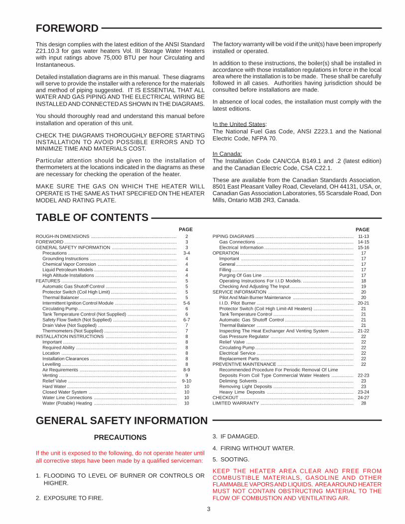
PIPING DIAGRAMS
(USE THIS DIAGRAM FOR STRAIGHT RECOVERYSYSTEMS SUPPLYING HOT WATER AT ONETEMPERATURE ONLY)
FIGURE 7
DANGERTEMPERATURE SETTING SHOULD NOT EXCEED SAFE USE TEMPERATURE ATFIXTURES. SEE WATER TEMPERATURE CONTROL WARNING ON PAGE 19. IF HIGHERPREHEAT TEMPERATURES ARE NECESSARY TO OBTAIN ADEQUATE BOOSTEROUTPUT, ADD AN ANTI-SCALD VALVE FOR HOT WATER SUPPLIED TO FIXTURES.

12
FIGURE 8
DANGERTEMPERATURE SETTING SHOULD NOT EXCEED SAFE USETEMPERATURE AT FIXTURES. SEE WATER TEMPERATURE CONTROLWARNING ON PAGE 19. IF HIGHER PREHEAT TEMPERATURES ARENECESSARY TO OBTAIN ADEQUATE BOOSTER OUTPUT, ADD ANANTI-SCALD VALVE FOR HOT WATER SUPPLIED TO FIXTURES.

13
FIGURE 9
FIGURE 10
DANGERTEMPERATURE SETTING SHOULD NOT EXCEED SAFE USE TEMPERATUREAT FIXTURES. SEE WATER TEMPERATURE CONTROL WARNING ONPAGE 19. IF HIGHER PREHEAT TEMPERATURES ARE NECESSARY TOOBTAIN ADEQUATE BOOSTER OUTPUT, ADD AN ANTI-SCALD VALVE FORHOT WATER SUPPLIED TO FIXTURES.

14
GAS CONNECTIONS
WARNINGTHE INLET GAS PRESSURE MUST NOT EXCEED THE VALUESPECIFIED BY THE MANUFACTURER ON THE RATING PLATE(10.5" W.C. - NATURAL GAS, 13.0" W.C. - PROPANE GAS).EXPOSURE TO HIGHER GAS SUPPLY PRESSURE MAY CAUSEDAMAGE TO THE GAS VALVE WHICH COULD RESULT IN FIREOR EXPLOSION. IF OVERPRESSURE HAS OCCURRED SUCHAS THROUGH IMPROPER TESTING OF GAS LINES OREMERGENCY MALFUNCTION OF THE SUPPLY SYSTEM, THEGAS VALVE MUST BE CHECKED FOR SAFE OPERATION. MAKESURE THAT THE OUTSIDE VENTS ON THE SUPPLYREGULATORS AND THE SAFETY VENT VALVES AREPROTECTED AGAINST BLOCKAGE. THESE ARE PARTS OFTHE GAS SUPPLY SYSTEM, NOT THE HEATER. VENTBLOCKAGE MAY OCCUR DURING ICE STORMS.
IT IS IMPORTANT TO GUARD AGAINST GAS VALVE FOULINGFROM CONTAMINANTS IN THE GAS WAYS. SUCH FOULINGMAY CAUSE IMPROPER OPERATION, FIRE OR EXPLOSION.
IF COPPER SUPPLY LINES ARE USED THEY MUST BEINTERNALLY TINNED AND CERTIFIED FOR GAS SERVICE.
BEFORE ATTACHING THE GAS LINE BE SURE THAT ALL GASPIPE IS CLEAN ON THE INSIDE.
TO TRAP ANY DIRT OR FOREIGN MATERIAL IN THE GASSUPPLY LINE, A DIRT LEG (SOMETIMES CALLED SEDIMENTTRAP OR DRIP LEG), MUST BE INCORPORATED IN THEPIPING. SEE PIPING DIAGRAMS. THE DIRT LEG MUST BEREADILY ACCESSIBLE AND NOT SUBJECT TO FREEZINGCONDITIONS. INSTALL IN ACCORDANCE WITHRECOMMENDATIONS OF SERVING GAS SUPPLIERS. IN THEUNITED STATES REFER TO ANSI Z223.1-1999 OR MOSTRECENT EDITION OF THE NATIONAL FUEL GAS CODE. INCANADA, THE CANADIAN INSTALLATION CODE CAN/CGAB 149 (LATEST EDITION).
To prevent damage, care must be taken not to apply too muchtorque when attaching gas supply pipe to gas valve gas inlet.
Fittings and unions in the gas line must be metal to metal type.
Apply joint compounds (pipe dope) sparingly and only to the malethreads of pipe joints. Do not apply compound to the first twothreads. Use compounds resistant to the action of liquefiedpetroleum gases.
BEFORE PLACING THE HEATER IN OPERATION, CHECK FORGAS LEAKAGE. Use soap and water solution or other material
acceptable for the purpose in locating gas leaks. DO NOT USEMATCHES, CANDLES, FLAME OR OTHER SOURCES OFIGNITION FOR THIS PURPOSE.
DISCONNECT THE HEATER AND ITS MANUAL GAS SHUTOFFVALVE FROM THE GAS SUPPLY PIPING SYSTEM DURINGANY PRESSURE TESTING OF THAT SYSTEM AT TESTPRESSURES IN EXCESS OF 1/2 PSIG. THE GAS SUPPLYLINE MUST BE CAPPED WHEN NOT CONNECTED TOHEATER.
THE HEATER MUST BE ISOLATED FROM THE GAS SUPPLYPIPING SYSTEM BY CLOSING ITS MANUAL GAS SHUTOFFVALVE DURING ANY PRESSURE TESTING OF THE GASSUPPLY PIPING SYSTEM AT TEST PRESSURES EQUAL TOOR LESS THAN 1/2 PSIG (3.44kPa).
CORRECT GAS
MAKE SURE the gas on which the heater will operate is the sameas that specified on the heater model and rating plate. Do notinstall the heater if equipped for a different type gas - contact theheater supplier.
SIZING GAS SUPPLY LINE
The iron pipe or equivalent pipe sizes in Table 6 are derived fromTable C-3 in the NATIONAL FUEL GAS CODE. The pipe sizesare based on a supply line gas pressure drop of 0.3 inches ofwater column from the gas meter to the point of installation of theheater(s). For natural gas, a heating value of 1050 Btu/ft3 and aspecific gravity of 0.60 has been assumed. A heating value of2500 Btu/ft3 and a specific gravity of 1.53 has been assumed forL.P. (propane) gas.
Where it is necessary to use an excess number of pipe fittings,i.e., elbows, tees and valves, in the gas supply line, use pipe atleast one size larger than that recommended in Table 2 tocompensate for the increased pressure drop.
If the service pressure is 4.5 inches W.C. (1.12kPa) (11 inches(1.74kPa) for L.P. gas) of water column or less, use pipe sizelarger than specified in Table 6 to minimize pressure drop in theline.
GAS METER SIZE - City Gases Only
Be sure that the gas meter has sufficient capacity to supply thefull rated gas input of the heater as well as the requirements of allother gas fired equipment supplied by the meter. If gas meter istoo small, ask the gas company to install a larger meter havingadequate capacity.
TABLE 6 GAS SUPPLY PIPE SIZES (IN INCHES)
NATURAL GAS (1050 Btu/ft3) PROPANE GAS (2500 Btu/ft3)Distance To HeaterFrom Meter (FT./M) HW-120M HW-160M HW-200M HW-225M HW-120M HW-160M HW-200M
10 (3M) 1/2 3/4 3/4 3/4 1/2 1/2 1/230 (9.1M) 3/4 3/4 1 1 1/2 3/4 3/4
50 (15.2M) 3/4 1 1 1 3/4 3/4 180 (24.4M) 1 1 1 1/4 1 1/4 3/4 1 1100 (30.5M) 1 1 1/4 1 1/4 1 1/4 3/4 1 1150 (45.7M) 1 1 1/4 1 1/4 1 1/4 1 1 1 1/4200 (61M) 1 1/4 1 1/4 1 1/4 1 1/2 1 1 1/4 1 1/4

15
ELECTRICAL WIRING DIAGRAMS FOR THE HW-120M, 160M, 200M AND 225M WATER HEATERSI.I.D. SYSTEM (NATURAL)
FIGURE 11
A minimum gas supply pressure of 4.5" W.C. (1.12kPa) for naturalgas and 11" W.C. (1.74kPa) for propane gas is required forpurposes of input adjustment.
ELECTRICAL INFORMATION
ALL ELECTRICAL WORK MUST BE INSTALLED INACCORDANCE WITH THE NATIONAL ELECTRICAL CODE INTHE UNITED STATES AND IN CANADA MUST CONFORM TOLOCAL REGULATIONS OR THE CANADIAN ELECTRICALCODE CSA C22.
The electrical connections must be made so that both the circulatorand intermittent ignition device operate simultaneously when thestorage tank temperature control calls for heat.
The appliance, when installed, must be electrically grounded inaccordance with local codes or, in the absence of local codes, inthe United States with the NATIONAL ELECTRICAL CODE, ANSI/NFPA 70. In Canada with the CANADIAN ELECTRIC CODE,CSA C22.
A screw is provided in the heater junction box for a groundconnection.
All piping diagrams include an electrical wiring diagram to assistthe installer in properly wiring of the additional componentsrequired to assure correct system operation.
Figures 11 and 12 show the heater mounted controls as they arewired when the heater leaves the factory. Using the individualwiring diagrams on the installation diagrams, the installer connectshis wiring to terminals in the heater(s) mounted junction box asshown.
All wiring should be done such that the heater(s) will operate inthe following manner:
1. When the tank temperature control calls for heat:
• The circulating pump starts to operate. Once the safety flowswitch contacts close, intermittent ignition device is poweredand sequence through steps as described for I.I.D. ControlModule on Page 5.
2. When the tank temperature control is satisfied:
• The main burners should stop firing, but the circulating pumpshould continue to operate for about 2 minutes when equippedwith a thermal balancer.
3. When the automatic gas shutoff control or coil protector switchoperate (break electric circuit):
• The main burners should stop firing. Circulating pump shouldcontinue to operate.

16
ELECTRICAL WIRING DIAGRAMS FOR THE HW-120M, 160M, AND 200M WATER HEATERSI.I.D. SYSTEM (PROPANE)
FIGURE 12
NOTES:

17
OPERATIONIMPORTANT
Only qualified personnel shall perform the initial firing of the heater.At this time the user should not hesitate to ask the start-uptechnician any questions regarding the operation andmaintenance of the unit.
Lighting and Operating instructions are included with this manual.By using these instructions, the user may be able to make minoroperational adjustments and save unnecessary service calls.However the user should not attempt repairs, but should contacta service technician or gas supplier.
GENERAL
Never operate the water heater without first making sure the waterheater and system are filled with water, in addition:
• Make sure a temperature and pressure relief valve is installedat the water heater and if used, the storage tank. Also checkfor leaks.
• Also be sure to check the gas piping for leaks before beginningthe initial firing of the boiler.
FILLING
1. Close the systems drain valve by turning handle clockwise.
2. Open a nearby hot water faucet to permit the air in the systemto escape.
3. Fully open the cold water inlet pipe valve allowing the heaterand piping to be filled.
4. Close the hot water faucet as water starts to flow.
5. The heater is ready to be operated.
PURGING OF GAS LINE
Gas line purging is required with new piping or systems in whichair has entered.
CAUTIONPURGING SHOULD BE PERFORMED BY PERSONSEXPERIENCED IN THIS TYPE GAS SERVICE. TO AVOID RISKOF FIRE OR EXPLOSION, PURGE DISCHARGE MUST NOTENTER CONFINED AREAS OR SPACES WHERE IGNITIONCAN OCCUR. THE AREA MUST BE WELL VENTILATED ANDALL SOURCES OF IGNITION MUST BE INACTIVATED ORREMOVED.
BEFORE PLACING THE WATER HEATER IN OPERATION,CHECK FOR GAS LEAKAGE. USE A SOAP AND WATERSOLUTION OR OTHER MATERIAL ACCEPTABLE FOR THEPURPOSE OF LOCATING GAS LEAKS. DO NOT USEMATCHES, CANDLES, FLAME OR OTHER SOURCES OFIGNITION FOR THIS PURPOSE.
CAUTIONBEFORE PROCEEDING WITH THE OPERATION OF THE UNIT,MAKE SURE HEATER AND SYSTEM ARE FILLED WITH WATERAND ALL AIR IS EXPELLED FROM HEATER AND PIPING.
THE MAIN MANUAL GAS SHUTOFF VALVE AND THE PILOTADJUSTING VALVE (WHEN APPLICABLE) MUST HAVE BEENCLOSED FOR AT LEAST FIVE (5) MINUTES. THIS WAITINGPERIOD IS AN IMPORTANT SAFETY STEP. ITS PURPOSE ISTO PERMIT GAS THAT MIGHT HAVE ACCUMULATED IN THECOMBUSTION CHAMBER TO CLEAR. IF YOU DETECT GASAT THE END OF THIS PERIOD, DO NOT PROCEED WITHLIGHTING. RECOGNIZE THAT GAS ODOR, EVEN IF IT SEEMSWEAK MAY INDICATE PRESENCE OF ACCUMULATED GASSOMEPLACE IN THE AREA WITH A RISK OF FIRE OREXPLOSION. SEE THE FRONT PAGE FOR STEPS TO BETAKEN.
DO NOT USE THIS HEATER IF ANY PART HAS BEEN UNDERWATER. IMMEDIATELY CALL A QUALIFIED SERVICETECHNICIAN TO INSPECT THE HEATER AND TO REPLACEANY PART OF THE CONTROL SYSTEM AND ANY GASCONTROL WHICH HAS BEEN UNDER WATER.
Light the unit in accordance with the instructions on the lightinglabel attached to the boiler. These instructions are repeated inthe following.

18
OPERATING INSTRUCTIONS FOR I.I.D. MODELS
The I.I.D. models have an automatic intermittent spark ignition system, figure 3, mounted on the jacket at the front of the heater whichignites the pilot gas whenever system controls call for heat.
Start the unit in accordance with the instructions on the operating label attached to the heater. These instructions are repeated in thefollowing.
1. SET THE THERMOSTAT TO LOWEST SETTING.2. TURN OFF ALL ELECTRIC POWER TO THE APPLIANCE IF SERVICE IS TO BE PERFORMED.3. TURN GAS VALVE CONTROL KNOB CLOCKWISE TO “OFF”. REFER TO STEP 5 OF “OPERATING INSTRUCTIONS” ABOVE.
A. THIS APPLIANCE IS EQUIPPED WITH AN IGNITIONDEVICE WHICH AUTOMATICALLY LIGHTS THEPILOT. DO NOT TRY TO LIGHT THE PILOT BY HAND.
B. BEFORE OPERATING SMELL ALL AROUND THEAPPLIANCE AREA FOR GAS . BE SURE TO SMELLNEXT TO THE FLOOR BECAUSE SOME GAS ISHEAVIER THAN AIR AND WILL SETTLE ON THEFLOOR.
WHAT TO DO IF YOU SMELL GAS• DO NOT TRY TO LIGHT ANY APPLIANCE.• DO NOT TOUCH ANY ELECTRIC SWITCH
DO NOT USE ANY PHONE IN YOUR BUILDING.• IMMEDIATELY CALL YOUR GAS SUPPLIER FROM
A NEIGHBOR’S PHONE. FOLLOW THE GASSUPPLIER’S INSTRUCTIONS.
• IF YOU CANNOT REACH YOUR GAS SUPPLIER,CALL THE FIRE DEPARTMENT.
C. USE ONLY YOUR HAND TO TURN THE GASCONTROL KNOB . NEVER USE TOOLS. IF THE KNOBWILL NOT TURN BY HAND, DON’T TRY TO REPAIRIT. CALL A QUALIFIED SERVICE TECHNICIAN.FORCE OR ATTEMPTED REPAIR MAY RESULT IN AFIRE OR EXPLOSION.
D. DO NOT USE THIS APPLIANCE IF ANY PART HASBEEN UNDER WATER. IMMEDIATELY CALL AQUALIFIED SERVICE TECHNICIAN TO INSPECT THEAPPLIANCE AND TO REPLACE ANY PART OF THECONTROL SYSTEM AND ANY GAS CONTROLWHICH HAS BEEN UNDER WATER.
E. DO NOT OPERATE APPLIANCE UNLESS UNIT ISFILLED WITH WATER AND INLET LINES AFTERFULLY OPEN.
WARNING: IF YOU DO NOT FOLLOW THESE INSTRUCTIONSEXACTLY A FIRE OR EXPLOSION MAY RESULT CAUSINGPROPERTY DAMAGE, PERSONAL INJURY OR LOSS OF LIFE.
1. STOP! READ THE SAFETY INFORMATIONABOVE ON THIS LABEL.
2. SET THERMOSTAT TO LOWEST SETTING.
3. TURN OFF ALL ELECTRIC POWER TO THEAPPLIANCE.
4. THIS APPLIANCE IS EQUIPPED WITH AN IGNITIONDEVICE WHICH AUTOMATICALLY LIGHTS THEPILOT. DO NOT TRY TO LIGHT THE PILOT BY HAND.
5. TURN GAS VALVE CONTROL KNOB CLOCKWISE TO “OFF” (FIG. A) A SLIGHT INDENT CAN BE FELTIN THE “OFF” POSITION.
6. WAIT FIVE (5) MINUTES TO CLEAR OUT ANY GAS.THEN SMELL FOR GAS, INCLUDING NEAR THEFLOOR. IF YOU THEN SMELL GAS.
STOP! FOLLOW “B” IN THE SAFETY INFORMATION ABOVE IN THIS LABEL.
IF YOU DON’T SMELL GAS. GO TO NEXTSTEP.
7. TURN GAS CONTROL KNOB COUNTERCLOCKWISE TO “ON” (FIG. B) UNTIL KNOB SNAPS INTO “ON”
POSITION.
8. TURN ON ALL ELECTRICAL POWER TO THEAPPLIANCE.
9. SET THERMOSTAT TO DESIRED SETTING. PILOTWILL BE IGNITED BY ELECTRONIC SPARK. WHENPILOT IGNITION IS SENSED, THE MAIN BURNERSWILL IGNITE.
10. IF MAIN BURNER FAILS TO IGNITE, REMOVEBURNER ACCESS DOOR AND FOLLOW SMALLMETAL TUBE FROM GAS VALVE TO PILOT. REPEATSTEPS 2 THRU 9. MAKE SURE PILOT IS BURNING.IF PILOT FAILS TO IGNITE, CHECK FOR PILOTIGNITION SPARK.
IF APPLIANCE WILL NOT OPERATE, FOLLOW THEINSTRUCTIONS “TO TURN OFF GAS TOAPPLIANCE” AND CALL YOUR SERVICETECHNICIAN OR GAS SUPPLIER.
FOR YOUR SAFETY READ BEFORE OPERATING
TO TURN OFF GAS TO APPLIANCE
OPERATING INSTRUCTIONS
HONEYWELL VR8304P GAS CONTROL

19
DANGERHOT WATER TEMPERATURES REQUIRED FOR AUTOMATICDISHWASHER AND LAUNDRY USE CAN CAUSE SCALDBURNS RESULTING IN SERIOUS PERSONAL INJURY AND/OR DEATH. THE TEMPERATURE AT WHICH INJURY OCCURSVARIES WITH THE PERSON’S AGE AND TIME OF EXPOSURE.THE SLOWER RESPONSE TIME OF CHILDREN, AGED ORDISABLED PERSONS INCREASES THE HAZARDS TO THEM.NEVER ALLOW SMALL CHILDREN TO USE A HOT WATERTAP, OR TO DRAW THEIR OWN BATH WATER. NEVER LEAVEA CHILD OR DISABLED PERSON UNATTENDED IN A BATHTUBOR SHOWER.
THE WATER HEATER SHOULD BE LOCATED IN AN AREAWHERE THE GENERAL PUBLIC DOES NOT HAVE ACCESSTO SET TEMPERATURES.
It is recommended in domestic hot water applications that lowerwater temperature be used to avoid the risk of scalding. It isfurther recommended, in all cases, that the water temperature beset for the lowest temperature which satisfies the user’s hot waterneeds. This will also provide the most energy efficient operationof the boiler and minimize scale formation in the heat exchanger,thus prolonging the life of the boiler.
SETTING THE WATER HEATER TEMPERATURE AT 120°F(49°C) WILL REDUCE THE RISK OF SCALDS. Some statesrequire settings at specific lower temperatures. The table belowshows the approximate time-to-burn relationship for normal adultskin.
Temperature Time to Produce 2nd & 3rdSetting Degree Burns on Adult Skin
Over 170°F (77°C) Nearly instantaneous160°F (71°C) About 1/2 seconds150°F (66°C) About 1-1/2 seconds140°F (60°) Less than 5 seconds130°F (54°) About 30 seconds
120°F (49°C) or less More than 5 minutes
Table 7
USE ANTI-SCALD VALVE(S) in the hot water system to reducethe risks of scalding at points of use such as lavatories, sinks andbathing facilities.
CAUTIONIN THE EVENT OF ELECTRIC POWER FAILURE, DO NOTATTEMPT TO OPERATE THE HEATER.
CHECKING AND ADJUSTING THE INPUT
The maximum inlet gas pressure must not exceed the valuespecified by the manufacturer (10.5" W.C. - natural gas,13.0" W.C. - propane gas). The minimum value listed on theRating Plate is for the purposes of input adjustment.
1. Turn the gas valve control knob to “OFF”, (See page 18).
2. Attach a pressure gauge or a manometer to the outlet pressuretap, figure 14 and refer to table 3 for correct manifold pressure.
3. Fire the heater by turning the gas valve control knob to “ON”.4. Use this formula to “clock” the meter. Be sure that other gas
consuming appliances are not operating during this interval.
3600 T x H = Btuh
T = Time (in seconds) to burn one cubic foot of gas.
H = Heating value of gas (in Btu’s per cubic foot of gas).
Btuh = Actual heater input (in Btuh).
EXAMPLE: (Using HW-120M heater)
T = 31.5 seconds/ft3
H = 1050 Btu/ft3
Btuh = ?
3600 x 1050 = 120,000 (compare with the ratings in31.5 Table 5).
Should it be necessary to adjust the gas pressure to the burnersto obtain the full input rate, the steps below should be followed.
5. Remove the regulator adjustment sealing cap, fig. 14, andadjust the pressure by turning the adjusting screw with ascrewdriver.
• Clockwise to increase gas pressure and input rate.
• Counterclockwise to decrease gas pressure and input rate.
DO NOT turn the adjusting screw in past the point of little or nomanifold pressure change or fully bottom the adjusting screw.
6. “Clock” the meter as in step 4 above.
7. Repeat steps 5 and 6 until the specified input rate is achieved.
8. Turn the gas valve control knob to “OFF”. Replace the regulatoradjustment sealing cap and remove the pressure gauge ormanometer from the outlet pressure tap. Using an allenwrench, replace the set screw in the outlet pressure tap.
9. Turn the gas valve control knob to “ON”.
If gas pressure regulator cannot be equipped to give the full inputrating with sufficient gas pressure at the valve, re-orifice the mainburners.
IMPORTANTUNDER NO CIRCUMSTANCES SHOULD THE GAS INPUTEXCEED THE INPUT SHOWN IN TABLE 2. OVERFIRINGCOULD RESULT IN DAMAGE OR SOOTING OF THE HEATER.
When the heater is operating at full capacity, or full gas input, itshould consume 1 cu. ft. of gas in approximately the amount oftime indicated in table 8.
TABLE 8 — TIME REQUIRED TO CONSUME 1 CUBIC FT. OF GAS(Heater operating at full input or full capacity.Does not apply to high altitude installations.)
Heating Total Time Required (Seconds) Value MODEL
Type of (Btu/ Gas Cu. Ft.) HW-120M HW-160M HW-200M HW-225M
Natural 1050 31.5 23.6 19.0 16.8Propane 2500 78.3 56.3 45.2 - - -

20
SERVICE INFORMATIONThe installer may be able to observe and correct certain problemswhich may arise when the unit is put into operation. HOWEVER,it is recommended that only qualified service personnel, usingappropriate test equipment, be allowed to service the heater.
Any safety devices used in conjunction with this appliance shouldreceive periodic (at least twice a year) inspection to assure properoperation. All relief valves should be inspected and manuallyoperated every six months.
PILOT AND MAIN BURNER MAINTENANCE
At least twice a year, check the pilot burner, fig. 15 and the mainburners, fig 13, for proper operation.
The burners should display the following characteristics:
• Provide complete combustion of gas.• Cause rapid ignition and carryover of flame across entire
burner.• Give reasonably quiet operation during ignition, burning and
extinction.• Cause no excessive lifting of flame from burner ports.
If the preceding burner characteristics are not evident, check foraccumulation of lint or other foreign material that restricts or blocksthe air openings to the burners or heater.
Also check for good flow of combustion and ventilating air to theunit. Maintain a clear area around the heater at all times.
Qualified servicers should follow this procedure when the heater’sburners need cleaning.
1. Turn off the electrical power and close the main manual gasshutoff valve.
• Allow heater parts to cool before disassembly.
2. Remove main burner manifold assembly from heater.
• Refer to parts list supplied with this manual for disassemblyaid.
3. Remove any loose foreign material such as dust or lint with avacuum. Check all ports, orifices and air openings for blockage.Dislodge any foreign material causing blockage. Do not usesharp metal objects to clean blocked orifices as they willdamage the soft brass orifice. Remove any soot or carbondeposits with a rag making sure to remove any lint left on burnerby vacuuming again.
MAIN BURNER FOR HW HEATERSFIGURE 13
4. Reinstall the burner manifold assembly on heater.
5. Restore electrical power and gas supply to heater.
• Check for gas leaks and proper heater and vent operation.
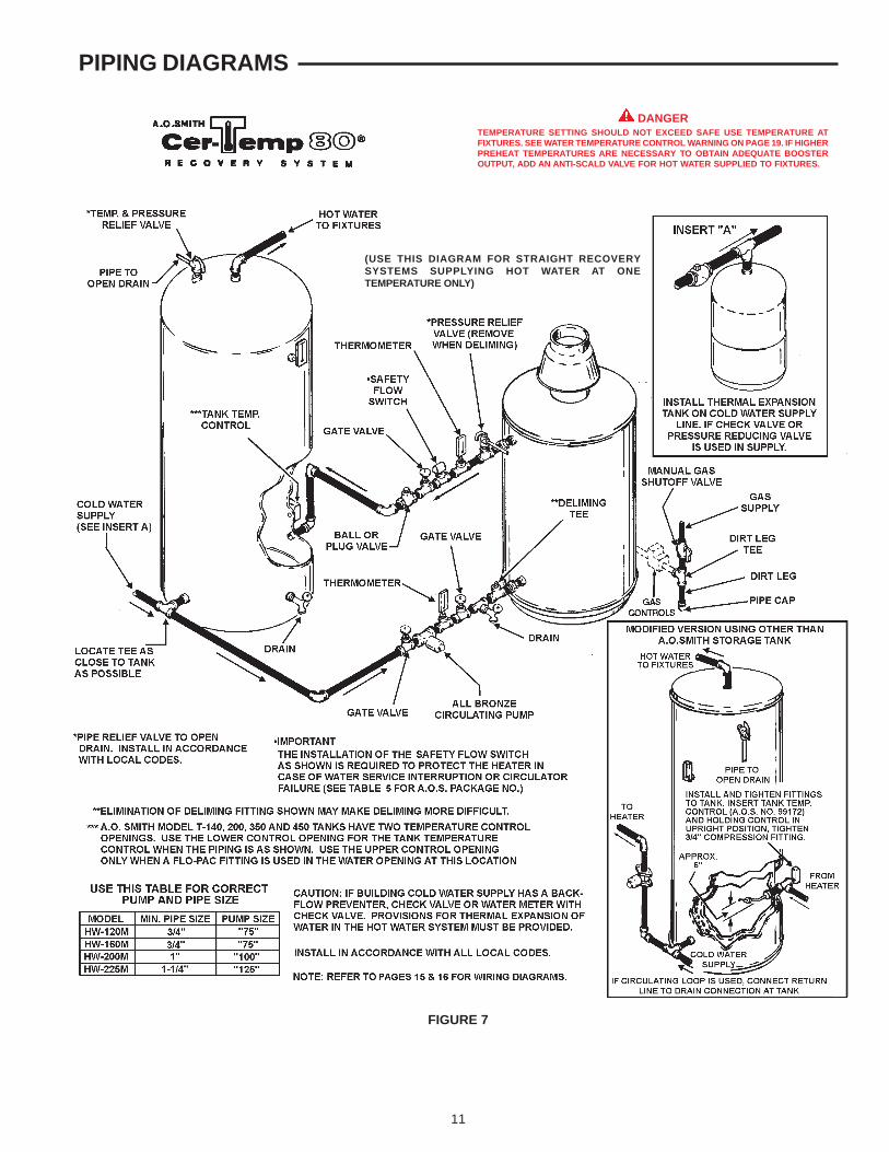
I.I.D. PILOT BURNER
Servicing of the pilot burner includes cleaning the burner headand the orifice of the pilot burner, fig. 15.
The pilot flame should envelop 3/8 to 1/2 in. of the tip of theinsulated rod on the igniter-sensor. If adjustment is required, it isnecessary to establish pilot flame without main burner operation.For this to happen, perform the following steps.
1. Follow “TO TURN OFF GAS TO APPLIANCE” steps in the“OPERATING INSTRUCTIONS FOR I.I.D. MODELS”.
2. Carefully disconnect the wire terminal connected to theMV terminal of the S8600 module, fig. 3.
3. Turn gas valve control knob counterclockwise to “ON”.
4. Turn on all electric power to the heater.
5. Set tank temperature control to call for heat. Pilot will operatewithout the main burners igniting.
6. Remove the pilot adjustment cover screw, fig. 14, and turn theinner adjustment screw clockwise to decrease orcounterclockwise to increase the pilot flame. Be sure toreplace cover screw after adjustment to prevent possible gasleakage.
7. Repeat step 1.
8. Carefully reconnect the MV wire terminal to the S8600 module.Be sure the terminal is securely connected.
9. Follow “OPERATING INSTRUCTIONS FOR I.I.D. MODELS”to put heater back into operation.
If the pilot burner ignites but the main burner fails to light, checkfor gas flow to the main burner.
Check for good terminal connections at the igniter-sensorconnector (fig. 15) and at the S8600 module.
For further assistance see Chart 2, “S8600 INTERMITTENT PILOTSYSTEM TROUBLESHOOTING”.
HONEYWELL GAS VALVE FOR I.I.D. SYSTEM (TOP VIEW)FIGURE 14
21
PILOT BURNER USED ON I.I.D. SYSTEMSFIGURE 15
PROTECTOR SWITCH(Coil High Limit - All Heaters)
If the protector switch, fig 2, should shut off unit, check for thefollowing conditions:
1. No water in heater.2. Restricted water flow through the heater.3. Excessive liming.4. Improper wiring (automatic gas shutoff control acting as primary
control).5. Pump failure.
After correcting failure condition, remove the protector switch coverand depress reset button. Button will not reset until watertemperature in heater coil is down to 2000F. Restart heater,following the “OPERATING INSTRUCTIONS FOR I.I.D.MODELS” , PAGE 18.
PROTECTOR SWITCH CONTINUITY TEST
Do not depress the protector switch reset button prior to testing.The leads from the switch are removed at the point farthest fromthe switch.
Attach the leads from a test flashlight to the switch leads.
The Model N22T test kit (combination flashlight and continuitytester) is manufactured by the Ray-O-Vac Company, Madison,WI and available through your local suppliers.
With the flashlight turned on, the lamp should light. If the lamplights, the protector switch circuit is closed and in proper workingorder. If the lamp does not light, the reasons could be:
1. Protector switch contacts open.• Depress reset button on switch (switch cannot be reset until
water temperature in the heater coil drops below 2000F).Lamp should light.
2. Defective protector switch or bad leads.• If lamp does not light when reset button is depressed, attach
the test flashlight leads to the protector switch terminals. Iflamp does not light, switch is defective and must be replaced.
• If lamp does not light, the leads are bad and must be repairedor replaced.
TANK TEMPERATURE CONTROL
The tank temperature control is the primary operating control ofthe system. The sensing element is mounted on the hot waterstorage tank. A change of temperature lower than the controlsetting will cause the element to activate the electrical switch andstart the heater.
If control is out of calibration, replace control.
AUTOMATIC GAS SHUTOFF CONTROL
The automatic gas shutoff control, fig. 1, is an automatic devicewhich is wired in series with the gas valve and intermittent ignitioncontrol module.
The control settings are fixed at 1950F (90.5°C) cut-out and 1900F(87.7°C) cut-in. Reduced water flow due to lime scaleaccumulation is one cause of frequent automatic gas shutoffcontrol operations. Refer to “PREVENTIVE MAINTENANCE”section for deliming instructions. If this non-adjustable control isout of calibration, replace control.
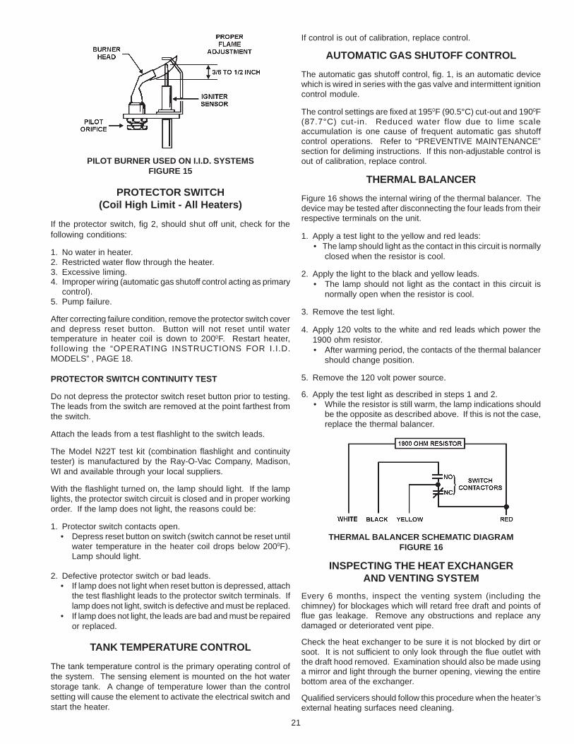
THERMAL BALANCER
Figure 16 shows the internal wiring of the thermal balancer. Thedevice may be tested after disconnecting the four leads from theirrespective terminals on the unit.
1. Apply a test light to the yellow and red leads:• The lamp should light as the contact in this circuit is normally
closed when the resistor is cool.
2. Apply the light to the black and yellow leads.• The lamp should not light as the contact in this circuit is
normally open when the resistor is cool.
3. Remove the test light.
4. Apply 120 volts to the white and red leads which power the1900 ohm resistor.• After warming period, the contacts of the thermal balancer
should change position.
5. Remove the 120 volt power source.
6. Apply the test light as described in steps 1 and 2.• While the resistor is still warm, the lamp indications should
be the opposite as described above. If this is not the case,replace the thermal balancer.
THERMAL BALANCER SCHEMATIC DIAGRAMFIGURE 16
INSPECTING THE HEAT EXCHANGERAND VENTING SYSTEM
Every 6 months, inspect the venting system (including thechimney) for blockages which will retard free draft and points offlue gas leakage. Remove any obstructions and replace anydamaged or deteriorated vent pipe.
Check the heat exchanger to be sure it is not blocked by dirt orsoot. It is not sufficient to only look through the flue outlet withthe draft hood removed. Examination should also be made usinga mirror and light through the burner opening, viewing the entirebottom area of the exchanger.
Qualified servicers should follow this procedure when the heater’sexternal heating surfaces need cleaning.
22
PREVENTIVE MAINTENANCERECOMMENDED PROCEDURE FOR PERIODIC
REMOVAL OF LIME DEPOSITS FROM COILTYPE COMMERCIAL WATER HEATERS
The amount of calcium carbonate (lime) released from water is indirect proportion to water temperature and usage, see fig. 17.
CAUTIONDO NOT USE A NYLON BRUSH OR OTHER STATIC CREATINGMATERIAL TO CLEAN DUST AND CARBON DEPOSITS FROMHEATING SURFACES AND VENT.
SUCH DEPOSITS ARE FLAMMABLE AND MAY BE IGNITEDBY STATIC ELECTRICITY. USE A METAL BRUSH TO MINIMIZETHE DANGER OF EXPLOSION.
1. Turn off the electrical power and main manual gas shutoff valve.• Allow heater parts and vent to cool before disassembly.
2. Remove the heater draft diverter and vent pipe running to thechimney.• Check parts and chimney for obstructions and clean as
necessary.• Replace any damaged or deteriorated parts of the venting
system.
3. Remove burners from heater and other metal parts as requiredto clean and vacuum the heat exchangers and combustioncoils.• Refer to parts list supplied with this manual for disassembly
aid.
4. Reinstall the parts removed in steps 2 and 3.• Be sure the vent pipe has a minimum upward pitch of one
quarter inch per foot of length and is sealed as necessary.
5. Restore electrical power and gas supply to heater.• Check for gas leaks and proper heater and vent operation.
Upon reassembly, a negative draft must be produced by thesystem. Check for proper draft by holding a lit match near thedraft hood opening while the heater is operating. The flame shouldbe drawn into the draft hood opening indicating proper draft.
GAS PRESSURE REGULATOR
The gas pressure regulator is included in the combination gasvalve, fig.14, and is set to operate on the gas specified on theheater model and rating plate.
Periodically check main burner, fig. 13, and pilot flame, fig. 15, forproper operation. This should be checked every six months.
Do not subject the gas valve to inlet gas pressure of more than10.5" W.C. - natural gas, 13.0" W.C. - propane gas. If higher gaspressures are encountered, a service regulator is necessary.
Check for a minimum inlet gas pressure value shown on the RatingPlate before making any adjustment of the regulator.
Attempts to adjust the regulator during periods of low gas supplypressure could result in overfiring of the heater when the gassupply pressure returns to normal.
DO NOT INCREASE PRESSURE ABOVE THAT SPECIFIED ASOVERFIRING WILL RESULT IN DAMAGE TO THE HEATER.If gas pressure regulator cannot be adjusted to correct pressure
with sufficient gas pressure at the valve, replace with new gasvalve.
RELIEF VALVEAt least twice a year the system relief valves should be checkedto ensure that they are in operating condition. To check a reliefvalve, lift the lever at the end of the valve several times. Thevalve should seat properly and operate freely.
CAUTIONBEFORE MANUALLY OPERATING A RELIEF VALVE, MAKESURE THAT A DRAIN LINE HAS BEEN ATTACHED TO THEVALVE TO DIRECT DISCHARGE TO AN OPEN DRAIN.FAILURE TO TAKE THIS PRECAUTION COULD MEANCONTACT WITH EXTREMELY HOT WATER EXITING THEVALVE DURING THE CHECK OPERATION.
If a relief valve discharges periodically or continuously, it may bedue to thermal expansion of water in a closed water supply system,or, it may be due to a faulty relief valve.
Thermal expansion is the normal response of water when it isheated. In a closed system, thermal expansion will cause thesystem pressure to build until the relief valve actuation pressureis equaled. Then the relief valve will open allowing some water toescape, slightly lowering the pressure.
Installation of a properly sized thermal expansion tank will usuallycorrect this problem. Contact your water supplier or local plumbinginspector for information on how to best correct this situation.
ABOVE ALL DO NOT PLUG ANY RELIEF VALVE. THIS IS NOTA SOLUTION AND CAN CREATE A HAZARDOUS SITUATION.
CIRCULATING PUMP
The circulating pump may require occasional lubrication. Referto circulator manufacturer’s instructions for lubrication procedures,and lubrication frequency.
ELECTRICAL SERVICE
CAUTIONLABEL ALL WIRES PRIOR TO DISCONNECTION WHENSERVICING CONTROLS. WIRING ERRORS CAN CAUSEIMPROPER AND DANGEROUS OPERATION.
VERIFY PROPER OPERATION AFTER SERVICING.
REPLACEMENT PARTS
Replacement parts may be ordered through A. O. Smith dealers,authorized servicers or distributors. Refer to the Yellow Pagesfor where to call or contact the A. O. Smith Water ProductsCompany, 5621 West 115th Street, Alsip, IL 60803,1-800-433-2545, or on the web at www.hotwater.com/parts. Whenordering parts be sure to state the quantity, part number anddescription of the item including the complete model and serialnumber as it appears on the product. Refer to the parts list formore information.
The higher the water temperature or water usage, the more limedeposits are dropped out of the water. This is the lime scalewhich forms in pipes, heaters and on cooking utensils.
Lime accumulation not only reduces the life of the equipment,but also reduces efficiency of the heater and increases fuelconsumption.

23
The usage of water softening equipment greatly reduces thehardness of the water. However, this equipment does not alwaysremove all of the hardness (lime). For this reason it isrecommended that a regular schedule for deliming be maintained.
The time between cleaning will vary from weeks to monthsdepending upon water conditions and usage. A change ofapproximately 50F in the normal temperature rise through theheater is usually an indication that scale should be removed. Forlong life, copper or brass is recommended for all valves, pipe andfittings used between gate valves “A” and “B” and the heater, seefig. 18.
Heater failure due to excessive lime build-up voids the warranty
.
FIGURE 17
DELIMING SOLVENTS
A. O. Smith recommends the use of UN•LIME® for deliming.UN•LIME is a patented food grade acid which is safe to handleand does not create the harmful fumes which are associated withother products.
UN•LIME may be obtained from your dealer, distributor or theA. O. Smith Water Products Company. Order part no. 4763(1 gal.), packed 4 gallons per case, or part no. 4813 (5 gal.container).
CAUTIONObserve handling instructions on label of product being used.
REMOVING LIGHT DEPOSITS
1. Shut off electric and gas supply to the burner.
2. Close gate valves “A” and “B”.
3. Install drain hose assembly in upper deliming tee. Open draincock and drain heater. Install standpipe in lower deliming teeor in tee from which pressure relief valve has been removed.
4. Close drain valve.
5. Slowly pour 3 gallons of UN•LIME into heater throughstandpipe. Direct solution into suitable container with a hose,see fig. 18.
DELIMING THE HW WATER HEATERFIGURE 18
6. Continue to fill until foaming action stops.
7. When foaming action has stopped completely, allow 10 to 15minutes for UN•LIME to dissolve any remaining scale in theheater.
8. Open the drain valve and drain all UN•LIME from the heater.
9. Remove standpipe and drain hose assembly from tees. Installfittings originally removed into openings. Open valve “A”,allowing fresh water to flow through heater and out drain valvefor 3 to 5 minutes.
10.Close drain valve and open valve “B”. Heater is now ready foroperation.
HEAVY LIME DEPOSITS
If the solvent does not readily pass through the clogged coils orheat exchanger, it will be necessary to use a deliming pump orcontact a service agency for proper cleaning.
A. O. Smith part no. 4930 motorized deliming pump kit, completewith pump, hoses, fittings, container and instructions, is availablefrom your dealer, distributor or A. O. Smith Water ProductsCompany.
A. O. Smith Form No. 4778, entitled “All About Deliming Coil TypeWater Heaters”, describes heater cleaning methods andequipment required. UN•LIME and the booklet may be obtainedthrough your dealer, distributor or A. O. Smith Water ProductsCompany.
FIGURE 19

24
CHART 1 - CER-TEMP 80 RECOVERY SYSTEM CHECKOUT PROCEDURE(Use this checkout for Cer-Temp 80 Recovery Systems)
CHECKOUTThe checkout sequence should be used as an on-the-job trouble-shooting guide to identify the cause of incorrect system operationand suggest a remedy for its correction.
Because improper piping and wiring can result in unsatisfactorysystem performance, it is suggested that the installation be
examined before using the checkout procedure. Be sure to referto the correct piping - wiring diagram and checkout for the type ofsystem that is installed.
The system should be filled with water, purged of air, valvesproperly set and utilities connected and ready to operate.
REMOVING SILICATE
Ammonium bifluoride flakes (NH4FlHF) are used in conjunctionwith A. O. Smith UN•LIME delimer and pump type deliming kit,part no. 4930, to delime and remove siliceous materials fromcopper coil water heaters.
• The part no. 4920 pump contained in the deliming kit isequipped with a titanium shaft. This shaft will not withstandammonium bifluoride solutions and must be replaced with astainless steel shaft, part no. 4926.
Ammonium bifluoride flakes should be purchased locally fromchemical suppliers. Contact your dealer, distributor or A. O. Smith Water Products Company for additional information.
SYSTEM OPERATIONCheckout Sequence Contact Incorrect Cause RemedySet tank temperature Circulating pump Pump and burner Tank temperature control Reduce differential.control 20° (11°C) below and burner shut remain on. differential wide.tank water temperature off.
With thermal Tank temperature control Replace.balancer, pump off defective.delay of approx-imately 2 minutes. System wiring is incorrect. Correct wiring.
Circulating pump Pump wired for continuous Correct wiring.on. operation.
Burner on. See intermittent pilot system troubleshooting chart 2.
Gas valve stuck or defective. Correct or replace valve.
System wiring in incorrect. Correct wiring.
Set tank temperature Circulating pump Circulating pump Automatic gas shutoff Replace. (If problemcontrol 20° (11°C) above and burner on. on. control calibrated too low proven to be at thistank water temperature. or differential too wide. control by applying
jumper to terminals.)
If system has been in See preventiveextended use it may maintenance.have lime build-up.
System wiring is incorrect. Correct wiring.
Gas valve or wiring Check wiring repair ordefective. replace valve.
See intermittent pilot system trouble-shooting chart 2.
Circulating pump Tank temperature control Reduce differential. A 5°and burner off. differential too great. differential is generally
used.
Power off or system wiring Check power supply andis incorrect. wiring.
Tank temperature control Replace.defective.
See intermittent pilot system trouble-shooting chart 2.
Burner on. System wiring is incorrect. Replace.
See intermittent pilot system trouble-shooting chart 2.
Heater outlet water Circulating pump Circulating pump Automatic gas shutoff Replace.temperature exceeds on. and burner on. control defective.210°F.
See intermittent pilot system trouble-shooting chart 2.
Set tank temperature System maintains.control for desired water desired watertemperature. temperature.

25
CHART 2S8600 (NATURAL GAS AND LP GAS)
INTERMITTENT PILOT SYSTEM TROUBLESHOOTING
NO SPARK AT PILOT BURNER
Turn gas supply off.
Is voltage (24 Vac) across the 24 V terminals on “Call for heat”?
Is voltage (24 Vac) across the PV & MV/PV terminals on“call for heat”?
NOTE: (FOR LP MODELS ONLY) Pilot valve will be de-energizedif module goes into lockout condition. Reset system by turningelectrical power off or by turning system controller to “OFF” or
down below “Call for heat”. Wait one minute then turn system on.
Turn off power supply.
Is ignition cable firmly plugged into module?
Is green ground wire firmly attached to mounting screwand GND terminal on module?
Ensure ground strap is the closest metal to the igniter/sensorrod (electrode) to prevent the spark from shorting outto other metal parts (pilot screen, pilot shield, etc.).
Ignition cable must not touch metal surfaces orcurrent carrying wires.
Is there a 1/8” gap between ground strap and electrode?
Are the ceramic insulators surrounding the electrodecracked or broken?
Replace pilot burner assembly or bus bar.
Replace ignition module.
Turn on gas supply.turn on power supply.
Securely connect cableand/or ground wire.
Carefully bend downwardtop of ground strap
to achieve 1/8”spark gap.
Replace ignitionmodule.
YES
NO
YES
YES
YES
YES
NO
NO
NO
NO
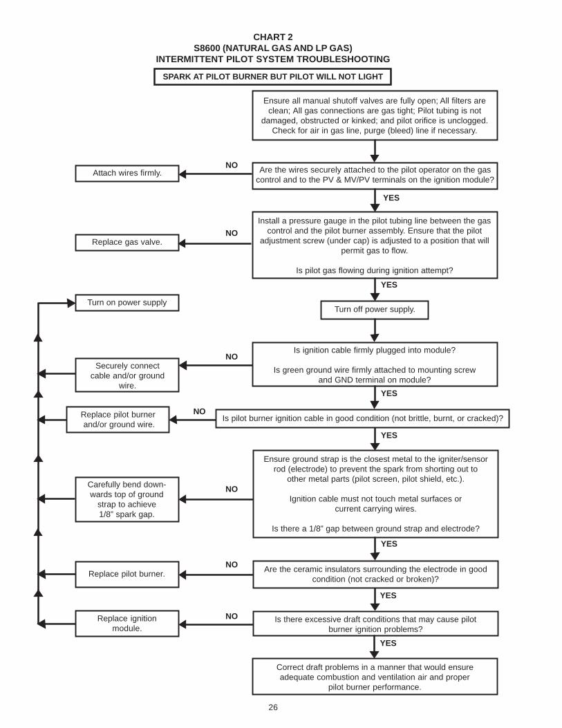
26
CHART 2S8600 (NATURAL GAS AND LP GAS)
INTERMITTENT PILOT SYSTEM TROUBLESHOOTING
Ensure all manual shutoff valves are fully open; All filters areclean; All gas connections are gas tight; Pilot tubing is not
damaged, obstructed or kinked; and pilot orifice is unclogged.Check for air in gas line, purge (bleed) line if necessary.
Are the wires securely attached to the pilot operator on the gascontrol and to the PV & MV/PV terminals on the ignition module?
Install a pressure gauge in the pilot tubing line between the gascontrol and the pilot burner assembly. Ensure that the pilot
adjustment screw (under cap) is adjusted to a position that willpermit gas to flow.
Is pilot gas flowing during ignition attempt?
Turn off power supply.
Is ignition cable firmly plugged into module?
Is green ground wire firmly attached to mounting screwand GND terminal on module?
Is pilot burner ignition cable in good condition (not brittle, burnt, or cracked)?
Ensure ground strap is the closest metal to the igniter/sensorrod (electrode) to prevent the spark from shorting out to
other metal parts (pilot screen, pilot shield, etc.).
Ignition cable must not touch metal surfaces orcurrent carrying wires.
Is there a 1/8” gap between ground strap and electrode?
Are the ceramic insulators surrounding the electrode in goodcondition (not cracked or broken)?
Is there excessive draft conditions that may cause pilotburner ignition problems?
Correct draft problems in a manner that would ensureadequate combustion and ventilation air and proper
pilot burner performance.
YES
YES
YES
YES
YES
YES
YES
NO
NO
NO
NO
NO
NO
NOAttach wires firmly.
Replace gas valve.
Turn on power supply
Securely connectcable and/or ground
wire.
Replace pilot burner and/or ground wire.
Carefully bend down-wards top of ground
strap to achieve1/8” spark gap.
Replace pilot burner.
Replace ignitionmodule.
SPARK AT PILOT BURNER BUT PILOT WILL NOT LIGHT

27
CHART 2S8600 (NATURAL GAS AND LP GAS)
INTERMITTENT PILOT SYSTEM TROUBLESHOOTING
PILOT BURNER LIGHTS BUT MAIN BURNER DOES NOT LIGHT
Does the pilot flame cover 3/8” to 1/2”of igniter/sensor rod?
Does spark stay on for more than 30 secondsafter the pilot is “proven” (lit)?
Is the pilot burner ignition cable in goodcondition (not brittle, burnt, or cracked)?
Are the ceramic insulators surrounding theigniter/sensor rod in good condition
(not broken or cracked)?
Are the igniter/sensor rod in goodcondition (not worn, corroded, sooted
or damaged)?
Replace ignition module.
Correct the situation by consulting theinstallation or user’s manual on how to
adjust pilot flame.
Is voltage (24 Vac) across terminalsMV & MV/PV?
Are the wires securely attached to the mainvalve operator on the gas control and to
terminals MV & MV/PV on ignition module?
Replaceignitionmodule.
Replace main gas valve.
Replace pilot burner.
Replace pilot burner.
Clean rod or replacepilot burner if necessary.
Attachwiresfirmly.
YES
YES
YES
YES
YES
NO
NO
NO
NO
NO
NO
NO
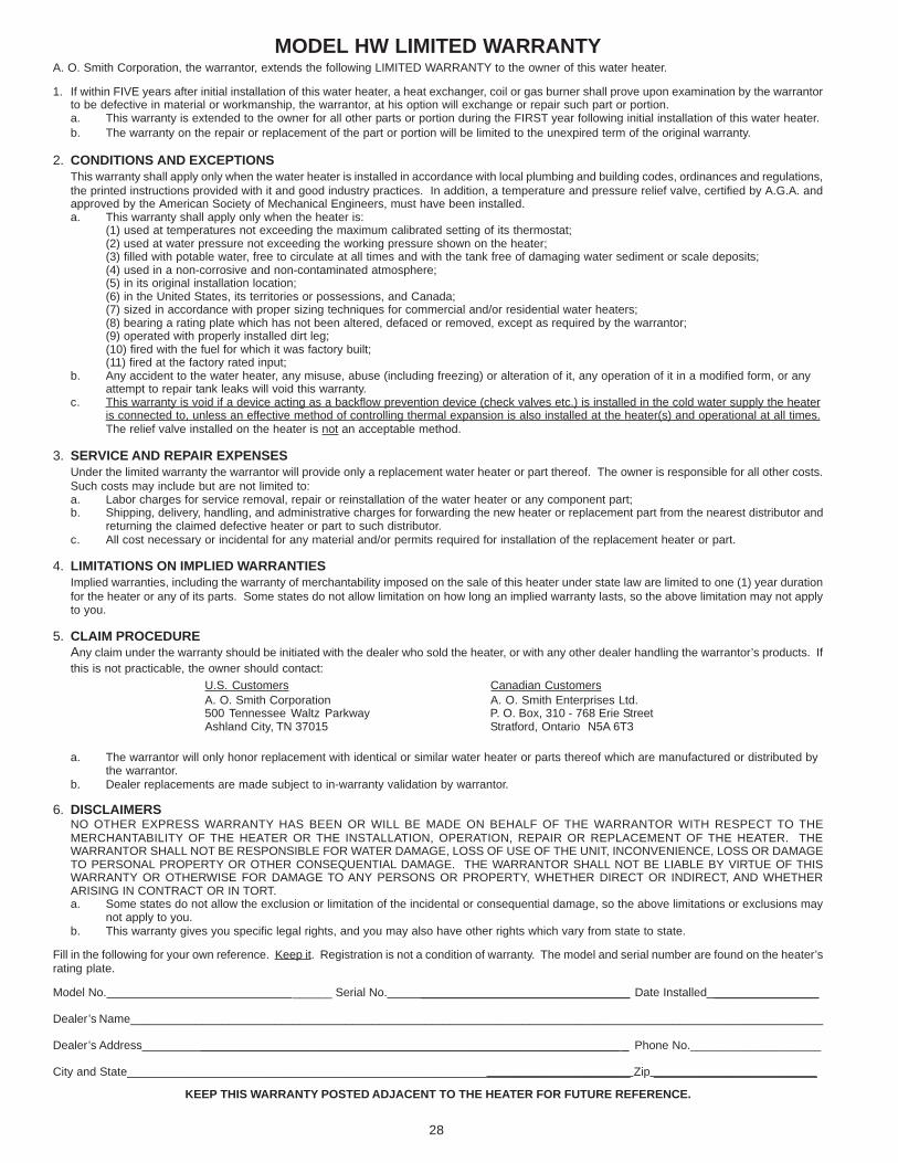
28
MODEL HW LIMITED WARRANTYA. O. Smith Corporation, the warrantor, extends the following LIMITED WARRANTY to the owner of this water heater.
1. If within FIVE years after initial installation of this water heater, a heat exchanger, coil or gas burner shall prove upon examination by the warrantorto be defective in material or workmanship, the warrantor, at his option will exchange or repair such part or portion.a. This warranty is extended to the owner for all other parts or portion during the FIRST year following initial installation of this water heater.b. The warranty on the repair or replacement of the part or portion will be limited to the unexpired term of the original warranty.
2. CONDITIONS AND EXCEPTIONSThis warranty shall apply only when the water heater is installed in accordance with local plumbing and building codes, ordinances and regulations,the printed instructions provided with it and good industry practices. In addition, a temperature and pressure relief valve, certified by A.G.A. andapproved by the American Society of Mechanical Engineers, must have been installed.a. This warranty shall apply only when the heater is:
(1) used at temperatures not exceeding the maximum calibrated setting of its thermostat;(2) used at water pressure not exceeding the working pressure shown on the heater;(3) filled with potable water, free to circulate at all times and with the tank free of damaging water sediment or scale deposits;(4) used in a non-corrosive and non-contaminated atmosphere;(5) in its original installation location;(6) in the United States, its territories or possessions, and Canada;(7) sized in accordance with proper sizing techniques for commercial and/or residential water heaters;(8) bearing a rating plate which has not been altered, defaced or removed, except as required by the warrantor;(9) operated with properly installed dirt leg;(10) fired with the fuel for which it was factory built;(11) fired at the factory rated input;
b. Any accident to the water heater, any misuse, abuse (including freezing) or alteration of it, any operation of it in a modified form, or anyattempt to repair tank leaks will void this warranty.
c. This warranty is void if a device acting as a backflow prevention device (check valves etc.) is installed in the cold water supply the heateris connected to, unless an effective method of controlling thermal expansion is also installed at the heater(s) and operational at all times.The relief valve installed on the heater is not an acceptable method.
3. SERVICE AND REPAIR EXPENSESUnder the limited warranty the warrantor will provide only a replacement water heater or part thereof. The owner is responsible for all other costs.Such costs may include but are not limited to:a. Labor charges for service removal, repair or reinstallation of the water heater or any component part;b. Shipping, delivery, handling, and administrative charges for forwarding the new heater or replacement part from the nearest distributor and
returning the claimed defective heater or part to such distributor.c. All cost necessary or incidental for any material and/or permits required for installation of the replacement heater or part.
4. LIMITATIONS ON IMPLIED WARRANTIESImplied warranties, including the warranty of merchantability imposed on the sale of this heater under state law are limited to one (1) year durationfor the heater or any of its parts. Some states do not allow limitation on how long an implied warranty lasts, so the above limitation may not applyto you.
5. CLAIM PROCEDUREAny claim under the warranty should be initiated with the dealer who sold the heater, or with any other dealer handling the warrantor’s products. Ifthis is not practicable, the owner should contact:
U.S. Customers Canadian CustomersA. O. Smith Corporation A. O. Smith Enterprises Ltd.500 Tennessee Waltz Parkway P. O. Box, 310 - 768 Erie StreetAshland City, TN 37015 Stratford, Ontario N5A 6T3
a. The warrantor will only honor replacement with identical or similar water heater or parts thereof which are manufactured or distributed bythe warrantor.
b. Dealer replacements are made subject to in-warranty validation by warrantor.
6. DISCLAIMERSNO OTHER EXPRESS WARRANTY HAS BEEN OR WILL BE MADE ON BEHALF OF THE WARRANTOR WITH RESPECT TO THEMERCHANTABILITY OF THE HEATER OR THE INSTALLATION, OPERATION, REPAIR OR REPLACEMENT OF THE HEATER. THEWARRANTOR SHALL NOT BE RESPONSIBLE FOR WATER DAMAGE, LOSS OF USE OF THE UNIT, INCONVENIENCE, LOSS OR DAMAGETO PERSONAL PROPERTY OR OTHER CONSEQUENTIAL DAMAGE. THE WARRANTOR SHALL NOT BE LIABLE BY VIRTUE OF THISWARRANTY OR OTHERWISE FOR DAMAGE TO ANY PERSONS OR PROPERTY, WHETHER DIRECT OR INDIRECT, AND WHETHERARISING IN CONTRACT OR IN TORT.a. Some states do not allow the exclusion or limitation of the incidental or consequential damage, so the above limitations or exclusions may
not apply to you.b. This warranty gives you specific legal rights, and you may also have other rights which vary from state to state.
Fill in the following for your own reference. Keep it. Registration is not a condition of warranty. The model and serial number are found on the heater’srating plate.
Model No. ______ Serial No. ________________________________ Date Installed ________________
Dealer’s Name__________________________________________________________________________________________________________
Dealer’s Address ________________________________________________________________ _ Phone No.____________________
City and State_____________________________________________________________________________ Zip _________________________
KEEP THIS WARRANTY POSTED ADJACENT TO THE HEATER FOR FUTURE REFERENCE.