Embed Size (px)
Citation preview

1
Tankless Water Heater Training Program
Product Knowledge / Installation Fundamentals
Level I/II
Title
Click here to advance slides.

2
This instructional presentation is provided by Rinnai America Corporation as a service to demonstrate common techniques used in installing and/or servicing Rinnai America products. An effort has been made to represent accurate and complete information at the time of publication; however, the information contained herein may not be current or applicable to specific products so review all available information and applicable codes.
Rinnai America expressly disclaims all liability (i) for any licensed professional or dealer relying solely on the information contained in this video without referencing the most recent information available from Rinnai America, for the latest and most detailed information as well as applicable plans and specifications, manuals of practice, codes, safety and health regulations with respect to Rinnai America products and (ii) for the installation or servicing of Rinnai America products by someone who is not a licensed professional familiar with all applicable codes.
Disclaimer

3 3
Designation Years of
production
Generation and
description
Other Notes
No specific letter
designation
1999-2001 1st Generation non-
condensing models
2402 and 2424 models only
“V” Series 2001-2006 2nd Generation non-
condensing models
Initially called “Continuum” and “Integrity.”
“VA” Series 2006-2010 3rd Generation non-
condensing models
Most VA models are also known as “LS” (except the
V53e)
2011 R98LS and V53e models still maintain the VA
designation.
“VB” Series
2010
4th Generation non-
condensing models
Most VB models still maintain the “LS” designation
(except the V53i)
2011 New for 2011 R75LS / R94LS models are now called
RL75 / RL94. V53 models are now called RV53. These
changes note the inclusion of isolation valves with the
product (LS designation no longer used for VB models)
“VC” Series 2012 5th Generation non-
condensing models
Additional Value Series units to include
V65i/e and V75i/e (V53i not produced any longer)
“KA” Series
2009-2010
1st Generation
condensing models
Also known as “HP” models (High Performance)
2011 New for 2011 RC series (80 and 98) now includes
isolation valves with the product (“HP” designation no
longer used)
“KB” Series 2012 2nd Generation
condensing models
Re-design of product and models are
now RU98i/e and RU80i/e
The Evolution of Rinnai Tankless
Water Heaters
Evolution
4
Model
Designation i=indoor models
e=outdoor
models
Full Model
Number
Minimum
Btu’s
Maximum
Btu’s
Minimum
Activation
Rate (approx.)
Maximum
Flow Rate
35° Temp
Rise
Maximum
Flow Rate
50° Temp
Rise
Efficiency
% or EF
Rating
V53e REU-VAM1620W 20.2 K – LP
19K - NG 120K 0.6 GPM 5.3 GPM 3.9 GPM .82
V65i REU-VC2025FFU 10.3K 152K 0.4 GPM 6.5 GPM 5.0 GPM .82
V65e REU-VC2025W
V75i REU-VC2528FFU 10.3K 180K 0.4 GPM 7.5 GPM 6.0 GPM .82
V75e REU-VC2528W
RL75i REU-VC2528FFUD 10.3K 180K 0.4 GPM 7.5 GPM 6.0 GPM .82
RL75e REU-VC2528WD
RL94i REU-VC2837FFUD 10.3K 199K 0.4 GPM 9.4 GPM 6.6 GPM .82
RL94e REU-VC2837WD
RU80i REU-KB2530FFUD 15.2K
157K 0.4 GPM 8.0 GPM 6.0 GPM .96
RU80e REU-KB2530WD 152K
RU98i REU-KB3237FFUD 15.2K 199K 0.4 GPM 9.8 GPM 7.6 GPM .95
RU98e REU-KB3237WD
Detailed individual model specifications are available—contact your local Rinnai representative or 1-800-621-9419
To remain the industry leader in tankless water heating, Rinnai is constantly improving our products- it is
important to attend Rinnai installation and service training classes on a regular basis
(preferably once per year)
Current Water Heater Model
Specifications
Current Model Specs

5
5
PRODUCT
FEATURES
Product Features
6 6
Rinnai Circ-Logic
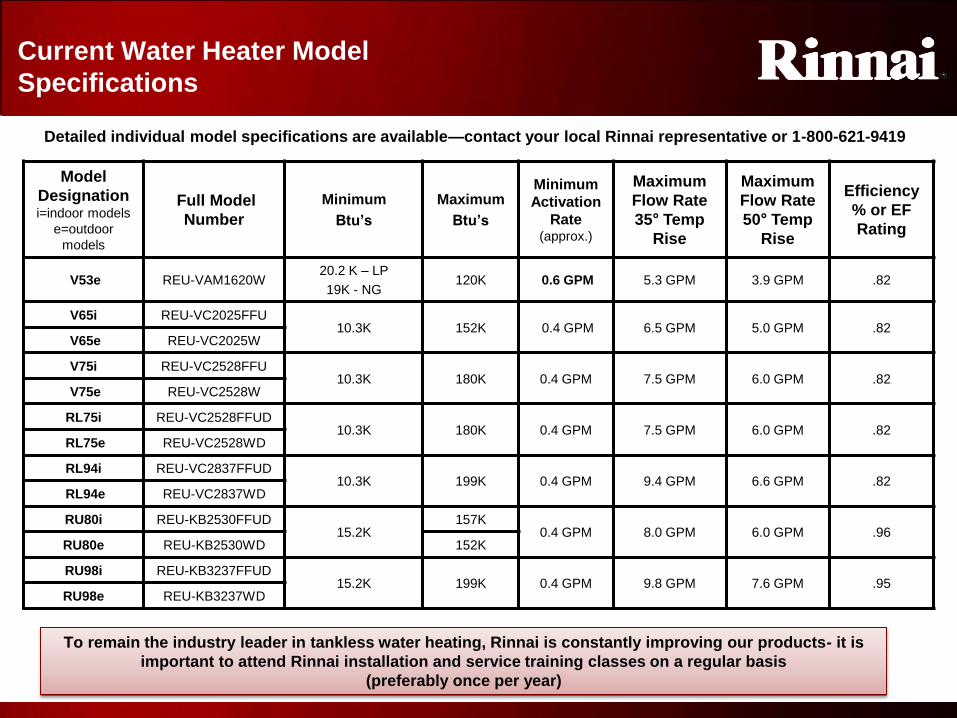
See pump cycle tables provided in Installation Instructions and Owners Manual
Rinnai Circ-Logic (RCL) offers homeowners enhanced convenience and energy
efficiency in home hot water recirculation systems with a dedicated return line. The
RCL controls the on/off sequence and operational cycles of the recirculation pump
through the programming of the tankless water heater’s control board.
This feature is standard on Rinnai’s Ultra and Luxury Series units.
Rinnai Circ Logic

7 7
Installation
1. Turn off the electrical supply by unplugging the
power cord or by turning off electrical power at
breaker.
2. Install the recirculation pump on the return line
according manufacturer installation instructions.
Install a check valve in the return line as shown in
the Plumbing Diagram if one is not integrated in the
pump.
Pump Requirements
Voltage: 120, 60 HZ
Amperage: less than 2 amps
NOTE: The Rinnai PC board will be damaged if
amperage exceeds 2 Amps.
Check valve: An integral flow check (IFC) valve is
required. See plumbing diagram.
The pump should be sized for 2.5 GPM at
the pressure loss through the tankless
water heater and the supply and return
plumbing in recirculation loop.
For more information on sizing the pump
refer to “Pump Sizing for Circulation” in
the Rinnai Hot Water System Design
Manual.
Note: Recirculation mode is for
residential installations only, and cannot
be used with the Bath Fill controller (BC-
100V), an air handler, or with multiple
Rinnai water heaters.
Installation

8 8
Installation
4. Adjust the (SW2) (bank of white) dip switches
as follows:
Economy mode, Switch 4 ON Switch 8 OFF
Comfort mode, Switch 4 ON Switch 8 ON.
5. Connect power to the water heater. Press
the power button on the controller. The pump
and water heater will turn on to raise the
recirculation loop temperature.
3. The wiring harness for the recirculation
pump is bundled with the wiring harness from
the PC board. The connector has a black and
white wire with the Label “Cut wire to connect
to pump”. To connect to the pump, cut the
connector, splice the wires and add a 4 Amp
fuse to hot wire (black) to the pump. Connect
the ground wire from the pump to a screw at
base of water heater cabinet.
( Refer to the pump Electrical Connection
Diagram. Follow Electrical Code and pump
manufactures recommendations.)
Installation

9 9
Sequence of Operation
Pump recirculation begins when the water heater is
turned on. The Rinnai inlet and outlet thermistors
measure the water temperature.
The water heater produces hot water at the
temperature setting. If the inlet thermistor detects
abnormal temperature then a diagnostic code 51 is
generated and the pump will turn off.
When the return water temperature reaches 15°F
(8.3°C) below the temperature setting the water
heater and pump will turn off.
The cycle will restart at the approximate time interval
in the table based on mode of operation and
temperature thermistor readings
* The pump will cycle on at these calculated intervals which are based on
the temperature setting, insulation, and estimated heat loss in the system.
The values for your installation may vary.
Note: The maximum Rinnai
temperature setting while in
recirculation mode is 140°F (60°C)
Sequence of Operation

1
0
10
Tankless Valve Kit
• Rinnai recommends the use of a tankless valve kit when connecting the water lines to the water heater
• All RL94, RL75, RU98, and RU80 models now include Webstone Isolation Valve kits!
• This kit includes hot and cold water shut-off valves, hot and cold water drain valves, and an ANSI approved PRV (pressure relief valve)
• This kit meets all individual states’ lead-free standards
• Use of this kit will assist in flushing the heat exchanger in areas where water quality issues exist, as well as improve overall product serviceability
• This kit is not included in the Value Series models.
Tankless Valve Kit

1
1
11
Product Features
ONLY RINNAI STANDS BEHIND ITS TANKLESS WATER HEATERS WITH A
LIMITED 5-YEAR EXTENDED LABOR WARRANTY!
RL / RU (Luxury/Ultra) Series Warranty (some restrictions
apply):
Heat exchanger limited warranty
12 years residential; 3 years when used in certain recirculating
systems; 10 years when used with a Rinnai hydronic furnace;
5 years in commercial applications.
All other parts: 5 years.
*Labor: 5 years residential and 2 years commercial for
Luxury/Ultra models when registered within 30 days of
installation, 1 year all other applications. All products installed
after March 31, 2011
Other models’ warranty guidelines may vary.
For more warranty details, visit www.rinnai.us or call
1-800-621-9419.
Product Features
1
2
12
Product Features
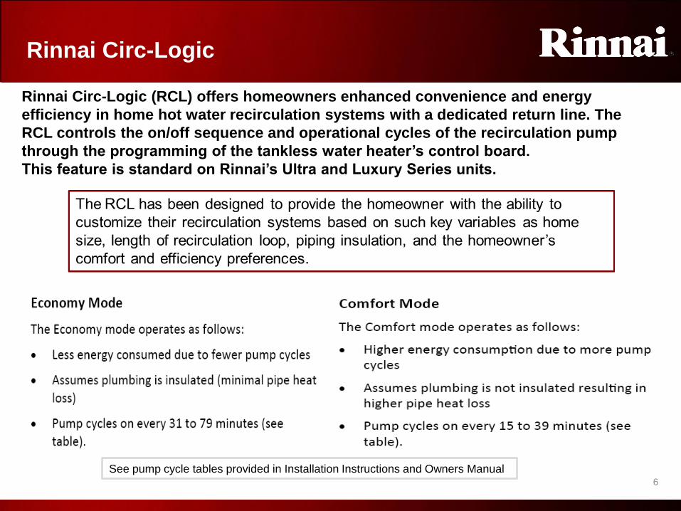
• Rinnai tankless water heaters have an industry leading activation rate of 0.4 gpm* and lower
minimum gas input rate of 10,000 Btu
• This allows ignition for smaller amounts of water at higher incoming temperatures
• Water flow deactivation is less than 0.26 gpm* (exceptions: V53e model)
• Current non-condensing models are approved for mobile homes installations (Exception: R98LS)
• Whole house continuous hot water system when properly sized
• Non-condensing models have EF ratings of .82-.84
• Condensing models have EF ratings of .95 - .96
• Temperature controller for setting desired water temperatures
• Output temperature can be adjusted to provide specific water temperatures for home, schools, nursing homes, hotels, etc.
• Locking capability of controller for safety
• Space saving, compact size
• Very low noise (49 decibels)
• All parts are replaceable
• †Life expectancy up to 15 – 20 years †Actual performance life will vary depending on water quality, usage rates, environmental conditions, and required maintenance scheduling. Refer to the
maintenance section of the operators manual for further details.
*Model Dependent
Product Features
1
3
13
Safety Devices
• Maintenance / diagnostic codes are displayed on the temperature controller, simplifying service calls
• Safe, low voltage temperature controllers
• Child safety lock on controller on current models
• Flame rod indicator(s) (validates and / or indicates flame failure)
• Over heat bi-metal sensor(s)
• Integrated boiling protection
• Heat exchanger thermal fuses
• Leak detection with Luxury and Ultra Series internal units
• Built-in freeze protection to -22º F for indoor units and -4º F for outdoor units (must have gas and electricity)
• A drain down kit can be obtained to protect the unit from freezing in case of electrical failure or inadequate gas supply—non-condensing models only
• Combustion fan senses blocked intake or exhaust flue
• Direct electronic ignition (no standing pilot)
• PC Board is protected by a glass fuse (size will vary by model)
Safety Devices

1
4
14
Tankless Water Heater
Sizing and Sequence
of Operation
Sizing and Sequence of
Operation
1
5
15
What is Delta T (∆T)?
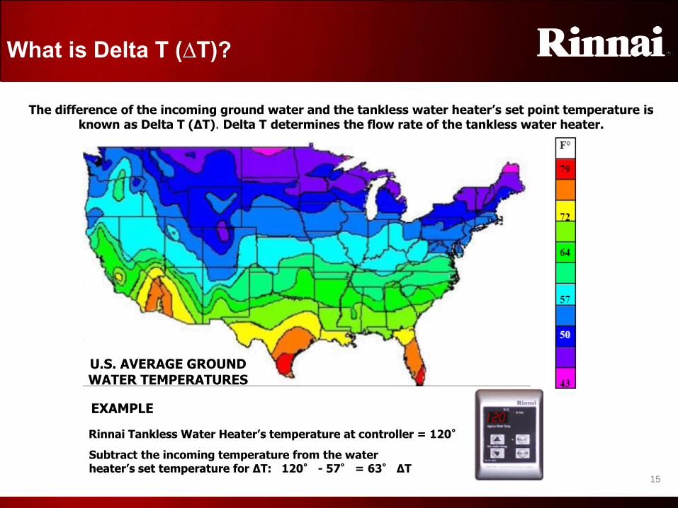
The difference of the incoming ground water and the tankless water heater’s set point temperature is known as Delta T (∆T). Delta T determines the flow rate of the tankless water heater.
U.S. AVERAGE GROUND WATER TEMPERATURES
EXAMPLE
Rinnai Tankless Water Heater’s temperature at controller = 120°
Subtract the incoming temperature from the water heater’s set temperature for ∆T: 120° - 57° = 63° ∆T
Delta T

1
6
16
Understanding Maximum Flow Rate
EXAMPLE (from previous page)
Incoming water = 57° Rinnai Set-Point temperature = 120°
• Subtract the incoming ground water temperature from the water heater’s set temperature for ∆T 120° - 57° = 63
• The maximum GPM flow rate for any given ∆T can be found at the intersecting points along each model’s specific
flow curve
• A GPM flow test from the temperature controller can verify each unit’s performance
RL94e
Flow
Curve
Flow curves of
each model are
listed in each
installation
manual
The tankless water heater’s first priority is to provide the set point temperature to the user. Based on the ∆T, the tankless product may regulate flow to ensure it can provide the selected temperature.
63
If incoming water is 57° and
requested temperature is 120°, ∆T
is 63° and gpm flow rate is 5.1
gpm
Maximum Flow Rate

1
7
17
Maximum Flow Rate by Model
Let’s focus on just the RL94 and RL75 models-Rinnai’s two main non-condensing products:
• Note that when the ∆T is greater than 50°F the difference in flow rate is less the 1gpm. Therefore, in areas where
the ground water is relatively cold, the RL75 is usually the model of choice for an average residential installation.
• In areas where the ground water is warmer, the RL94 will provide substantially more output than an RL75
Flow Rate by Model

1
8
18
Whole-House Sizing Chart
• Assumed mixed temperature on shower heads and bathroom faucets are set to 104º F
WHOLE HOUSE SIMULTANEOUS BATH USE To make things simpler, a basic sizing chart can be used based on ground water temperature. Please note the below factors as well:
• Assumed Rinnai water heater set point at 120º F
• Assumed 50 psi – 80 psi inlet water pressure for maximum flow
• A residential washing machine or dishwasher is equivalent to one shower head
• Bathroom sink faucets assumed to be 2 gpm mixed flow rate or less
• Shower heads assumed to be 2.5 gpm mixed flow rate or less.
• 2.5 gpm is a standard size for most residential shower heads
• If multiple shower fixtures (i.e. body sprays, large rain heads, or tubs over 60 gallons in capacity) are used, please contact Rinnai’s applications and sizing group
RU80i/e
RU98i/e + +
RL75i/e
RL94i/e
(R)V53i
(R)V53e
Sizing Chart

1
9
19
1. Water flow begins • Water flow sensor sends pulses to the PCB
• When flow exceeds approximately *0.4 gpm the ignition sequence begins.
2. Ignition Sequence • Combustion fan turns to allow correct air flow thru unit
• Spark igniter begins sparking and gas control valve opens to low fire rate
• When flame rods prove ignition spark igniter stops sparking
3. Normal Operation • PCB monitors flame rods, fan motor frequency, flame characteristic, outlet water
temperature, temperature set point, and water flow rate
• Gas valve assembly & fan speed modulate gas and air input to meet user demand
• If demand is very small, only SV1 will allow gas to burner, FR1 will monitor this
minimum fire state
• If demand is large flame can develop across the entire burner
• Water is heated as it passes thru heat exchanger multiple times
• Heat exchanger strategically overheats water while the fixed or variable bypass
cools to the set point temperature to provide higher flow rates
• Water flow control valve is adjusted, as needed
4. Shut-down Sequence • PCB senses flow rate less than *0.26 gpm
• Gas control valve closes & water flow control valve resets to standby position
• Combustion fan runs for a short period of time at low speed
5. Standby Mode • PCB monitors all components. Freeze protection is activated as needed *Model dependent
Water Flow
Sensor
PCB
Combustion Fan
Igniter
SV4
SV0 or SV Main
Modulating
Gas Valve/POV
Water flow
control valve
Out going
Temperature
Thermistor
Incoming Air Exhaust
Heat Exchanger Temp.Thermistor
Bypass
Sequence of Operation (VC) (indoor RL Non-condensing model)
FR 2
FR 1
SV2
SV1 SV3
VC Sequence of Operation

2
0
20
INSTALLATION
REQUIREMENTS
Installation Requirements

2
1
21
Manufactured Home Installation
• Modular Homes
• A modular, panelized, or precut home is built at a factory and then transported to the site and assembled.
These types of construction fall under the regulation of the model building code enforced in the
jurisdiction where the home is to be located.
• All Rinnai water heaters are approved for installation in modular, panelized, or precut homes
• Manufactured Homes (or Mobile Homes)
• The ANSI standard defines a manufactured home as a structure, transportable in one or more sections,
which in the traveling mode, is eight body feet or more in width or forty body feet or more in length, or
when erected on site, is 320 or more square feet.
• Rinnai R75/RL75, R94/RL94, and V53i/RV53i , V65, and V75 models with “VB” or “VC” in the
full model number are approved by CSA for installation in manufactured or mobile homes
• Rinnai V53e/RV53e models manufactured in April, 2010 or later are also approved by CSA for
installation in manufactured or mobile homes
• At the time of this publication, all other Rinnai model water heaters are not approved for manufactured
or mobile home installation. Contact Rinnai if needed for a current list of approved models.
• Furthermore, the ANSI standard requires that all products for installation in manufactured homes be CSA
certified with required labeling and instructions as well the ability to field convert gas type as necessary.
• VB and VC models meet these requirements
• Most models prior to the VB series were also gas type convertible, however only VB models are
approved to this standard for installation in manufactured homes.
• VB and VC models are also approved to retrofit into existing manufactured homes (local and state codes
may apply)
Manufactured Homes
2
2
22
Product Installation Key Points (All current Rinnai models)
• Rinnai’s tankless water heaters can be used in both residential and commercial applications
• Exception: Value Series models are not to be used in commercial applications
• Units are available as either natural or propane gas
• Indoor models must be installed within the confines of a structure. This includes carports and
crawlspaces. Outdoor models must be installed outside.
• Residential installations are potable water applications only in single family dwellings with a
maximum water temperature setting of 140ºF
• Commercial installations are potable water applications for restaurants, schools, hotels, car
washes, coin laundries, assisted living facilities, etc. Hydronic applications are also defined as
commercial installations.
• The MCC-91 commercial temperature controller (optional) allows a maximum water
temperature setting of 160º F on V53, V65 and V75/RL75 models
• The MCC-91 commercial temperature controller (optional) allows a maximum water
temperature setting of 185º F on the RL94,RU80,RU98 and R98LS models
DO NOT use these units in any application involving chemically treated water, (i.e. chlorinated
pool water, hot tubs, etc,)
Installation Key Points
2
3
23
Installation Check-List (All current models)
Attached to the front of every Rinnai water heater is an installation check list. It is important to review
this list BEFORE the installation and again BEFORE commissioning the product to ensure proper
operation. Below is an overview:
Ensure the manual gas valve packaged with the water heater is installed in the gas supply line
Ensure 120 Volts A.C. is connected to the unit, properly grounded, and that the circuit is turned on
Verify the gas system is functioning correctly by connecting a manometer to the gas pressure test
port on the unit. Operate all gas appliances in the facility at high fire. The inlet gas pressure on the
unit must not drop below that listed on the unit’s rating plate for the gas type being used.
Make sure you have cleaned the COLD water inlet filter screen
Inspect Hot (outlet) & Cold (inlet) water lines to ensure they have not been crossed & are leak free
– (Hot – Left) – (Cold – Center) – (Gas – Right)
Ensure the temperature controller is installed and functioning. Instruct the customer how to
operate the temperature controller. Instructions are supplied in the Use & Care Manual. A typical
water heater set point (water temperature) is 120º F.
Explain to the customer the importance of never blocking the intake or exhaust venting. They
should never store anything around the vent exhaust.
Ensure the condensation drain is connected and drained per local code (condensing models only)
Installation Check List

2
4
24
Installation Requirements (All current models)
It is very important to ensure the following incoming sources are within specification:
• Electricity –
• A properly polarized and grounded 120 VAC, 60 Hz supply is required. Temperature
controllers operate on 12 VDC only supplied by the water heater.
• Water –
• Pipe sizing and incoming water pressure must meet each model’s requirements as stated in the installation manual; and, water quality must meet the EPA’s National Secondary Drinking Standards
• Gas –
• Adequate gas pressure and volume (gas line sizing) must be verified for proper operation
• Venting (air) –
• Vent components that are certified and listed with the water heater model must be installed to
specifications and proper clearances must be maintained
• Code Adherence –
• All national, state, and local codes must be followed
Installation Requirements

2
5 25
Installation Requirements (All current models)
Important:
Observe all applicable electrical codes. Circuit must
be well grounded to earth for proper operation of the
water heater.
Outdoor Models Indoor Models
Internal units come
with a standard three-
prong appliance cord.
Ensure receptacle is
properly polarized and
grounded 120 VAC.
External units come with a hot
and neutral wire and a ground
connection point for direct
connection to supply (i.e.
circuit breaker box). Ensure
supply is properly polarized
and grounded 120 VAC.
ELECTRICAL REQUIREMENTS
Entry point for electrical connections
Supply power should enter the water heater
through the center opening at the bottom of the
unit
Temperature controller wire should enter the
water heater through the left opening at the
bottom of the unit.
120 VAC Input
Temperature Controller wire input
Ground Connection
120 VAC input Black – Hot
White - Neutral
Installation Requirements

2
6 26
Installation Requirements (All current models)
• WATER PRESSURE • Minimum water pressure 20 psi (non-condensing models), 50 psi (condensing models)
• Maximum water pressure 150 psi
• Rinnai recommends 30-80 psi for optimum performance for non-condensing models
• Rinnai recommends 60-80 psi for optimum performance for condensing models
• ANSI Code requires the addition of an approved pressure relief valve
• Valve must be rated No-More than 150 psi and No-Less than the water heater’s maximum Btu input
• INCOMING PIPING REQUIRMENTS
• All performance data of Rinnai Water Heaters are based on systems plumbed with ¾” pipe
(unless otherwise noted). Performance may vary with other pipe sizes.
• WATER QUALITY
• For proper operation, unit longevity, and warranty adherence, water quality cannot exceed
the parameters set forth by the EPA’s National Secondary Drinking Standard’s Act:
DESCRIPTION pH TDS (Total
Dissolved Solids)
Total
Hardness
Aluminum Chlorides Copper Iron Manganese Zinc
MAXIMUM
LEVELS
6.5
to
8.5
Up to 500 mg/L Up to 200
mg/L
(11.7 gpg)
Up to 0.2
mg/L
Up to 250
mg/L
Up to 1.0
mg/L
Up to
0.3
mg/L
Up to 0.05
mg/L
Up to
5
mg/L
WATER REQUIREMENTS
Installation Requirements

2
7
27
Gas Supply (All current models)
• A manual gas control valve must be installed in the gas supply line prior to the unit
• An easy means of disconnection (such as a union) should be above the shut-off valve for future servicing of
the water heater
• Supplied gas pressure must be within the limits shown on the rating plate or specification section listed for
each product
• Tankless water heaters require a higher gas supply than tank water heaters. Consider the following:
• An average 40 gallon gas-fired tank has a maximum input rating of approximately 45,000 Btu
• A Rinnai tankless water heater has a maximum input rating of approximately 199,000 Btu
• The variance in is 154,000 Btu’s. Sizing of the gas supply system and meter capacity must be considered when increasing a structure’s total Btu load
• Issues caused by insufficient gas supply:
• Poor appliance operation and/or water heater diagnostic codes
• Rumbling noises due to insufficient air/gas mixture
• Summer installations sometimes operate correctly until winter appliances are operated—causing delayed performance issues
• Testing gas pressure while all gas appliances are operating at full capacity can prevent such issues
U-tube or Slack tube manometers
Digital manometers
• If any symptom exists suggesting a gas supply issue may
be present, a gas manometer will be needed to verify
incoming pressure. Rinnai tankless water heaters only need
a single port manometer. Dual port or pressure differential
manometers are not needed. Some common manometers
are shown:
Gas Supply
2
8
28
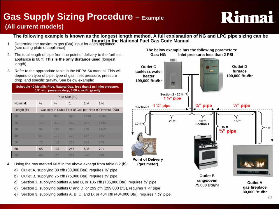
Gas Supply Sizing Procedure – Example
(All current models)
Point of Delivery
(gas meter)
Outlet B
range/oven
75,000 Btu/hr Outlet A
gas fireplace
30,000 Btu/hr
Outlet D
furnace
100,000 Btu/hr
Outlet C
tankless water
heater
199,000 Btu/hr
10 ft 20 ft 10 ft
Section 1 15 ft
Section 2 - 20 ft
1. Determine the maximum gas (Btu) input for each appliance (see rating plate of appliance)
2. The total length of pipe from the point of delivery to the farthest
appliance is 60 ft. This is the only distance used (longest
length).
3. Refer to the appropriate table in the NFPA 54 manual. This will
depend on type of pipe, type of gas, inlet pressure, pressure
drop, and specific gravity. See below example:
Section 3
The below example has the following parameters:
Gas: NG Inlet pressure: less than 2 PSI
Schedule 40 Metallic Pipe, Natural Gas, less than 2 psi inlet pressure,
0.5” w.c. pressure drop, 0.60 specific gravity
Pipe Size (in.)
Nominal: ½ ¾ 1 1 ¼ 1 ½
Length (ft) Capacity in Cubic Feet of Gas per Hour (CFH=Btu/1000)
10 172 360 678 1390 2090
20 118 247 466 957 1430
30 95 199 376 768 1150
40 81 170 320 657 985
50 72 151 284 583 873
60 65 137 257 528 791
70 60 126 237 486 728
4. Using the row marked 60 ft in the above excerpt from table 6.2.(b):
a) Outlet A, supplying 30 cfh (30,000 Btu), requires ½” pipe
b) Outlet B, supplying 75 cfh (75,000 Btu), requires ¾” pipe
c) Section 1, supplying outlets A and B, or 105 cfh (105,000 Btu), requires ¾” pipe
d) Section 2, supplying outlets C and D, or 299 cfh (299,000 Btu), requires 1 ¼” pipe
e) Section 3, supplying outlets A, B, C, and D, or 404 cfh (404,000 Btu), requires 1 ¼” pipe.
The following example is known as the longest length method. A full explanation of NG and LPG pipe sizing can be found in the National Fuel Gas Code Manual
5 ft 15 ft
½” pipe
¾” pipe
¾” pipe 1 ¼” pipe
1 ¼” pipe
Gas Supply Sizing

2
9
29
Schedule 40 Metallic Pipe, Natural Gas, less than 2 psi inlet pressure,
3.0” w.c. pressure drop, 0.60 specific gravity
Pipe Size (in.)
Nominal: ½ ¾ 1 1 ¼ 1 ½
Length (ft) Capacity in Cubic Feet of Gas per Hour (CFH=Btu/1000)
10 454 949 1,787 3,669 5,497
20 312 652 1,228 2,522 3,778
30 250 524 986 2,025 3,034
40 214 448 844 1,733 2,597
50 190 397 748 1,536 2,302
60 172 360 678 1,392 2,085
70 158 331 624 1,280 1,919
The following example is from a newly approved table in the NFPA 54 manual, which in some cases allows for smaller gas pipe sizing. Again using the longest length method.
1. Determine the maximum gas (Btu) input for each appliance (see rating plate of appliance)
2. The total length of pipe from the point of delivery to the farthest
appliance is 60 ft. This is the only distance used (longest
length).
3. Refer to the appropriate table in the NFPA 54 manual. This will
depend on type of pipe, type of gas, inlet pressure, pressure
drop, and specific gravity. See below example:
4. Using the row marked 60 ft in the above excerpt from table 6.2.(c):
a) Outlet A, supplying 30 cfh (30,000 Btu), requires ½” pipe
b) Outlet B, supplying 75 cfh (75,000 Btu), requires ½” pipe
c) Section 1, supplying outlets A and B, or 105 cfh (105,000 Btu), requires ½” pipe
d) Section 2, supplying outlets C and D, or 299 cfh (299,000 Btu), requires ¾” pipe
e) Section 3, supplying outlets A, B, C, and D, or 404 cfh (404,000 Btu), requires 1” pipe.
Point of Delivery
(gas meter)
Outlet B
range/oven
75,000 Btu/hr
Outlet A
gas fireplace
30,000 Btu/hr
Outlet D
furnace
100,000 Btu/hr
Outlet C
tankless water
heater
199,000 Btu/hr
The below example Intended use is with initial supply
pressure of 8”w.c. or greater.
Gas Supply Sizing Procedure
Section 3
10 ft
Section 2 - 20 ft
20 ft 10 ft Section 1
15 ft
5 ft 15 ft
1 ” pipe
¾” pipe
½” pipe ½” pipe
½” pipe
Gas Supply Sizing

3
0
30
Gas System – Two stage piping example
(All current models)
If resizing gas supply lines is not a feasible option, a two stage supply system may be used depending on
local code guidelines. Two stage systems operate in the following manner:
Point of Delivery (gas meter)
Outlet B range/oven
75,000 Btu/hr
Outlet A gas fireplace 30,000 Btu/hr
Outlet D furnace
100,000 Btu/hr
Outlet C tankless water
heater 199,000 Btu/hr
• Higher pressure (usually 2 lbs or
approximately 56” w.c.) is supplied for a large
portion of the supply system.
• Regulators are placed close to each appliance
to reduce pressure to the appliance standard
of ½ lb or approximately 7-14” w.c.
• This system overcomes volume inadequacies
by raising the pressure. NOTE: Never apply
high pressure (such as 2 lbs) to a household
appliance unless stated by the manufacturer.
All Rinnai tankless water heaters require no
more than ½” lb inlet pressure (14” w.c.).
• Using the previous example, if the existing
gas line did not meet the NFPA standard for ½
lbs pressure, the following two stage
implementation could be an alternative
• Follow NFPA 54 guideline and all code
requirements when sizing two stage systems.
• Two stage systems can be used in NG or LP
applications—sizing values differ by gas type
• Gas meter capacity must also be considered
Main gas meter supplies 2 lbs of pressure through
existing pipes
Regulators are placed in close vicinity to all appliances bringing pressure to appliance
standard (1/4-1/2 lb)
The below example has the following parameters Gas: NG Inlet pressure: 2 PSI
Gas System
3
1
31
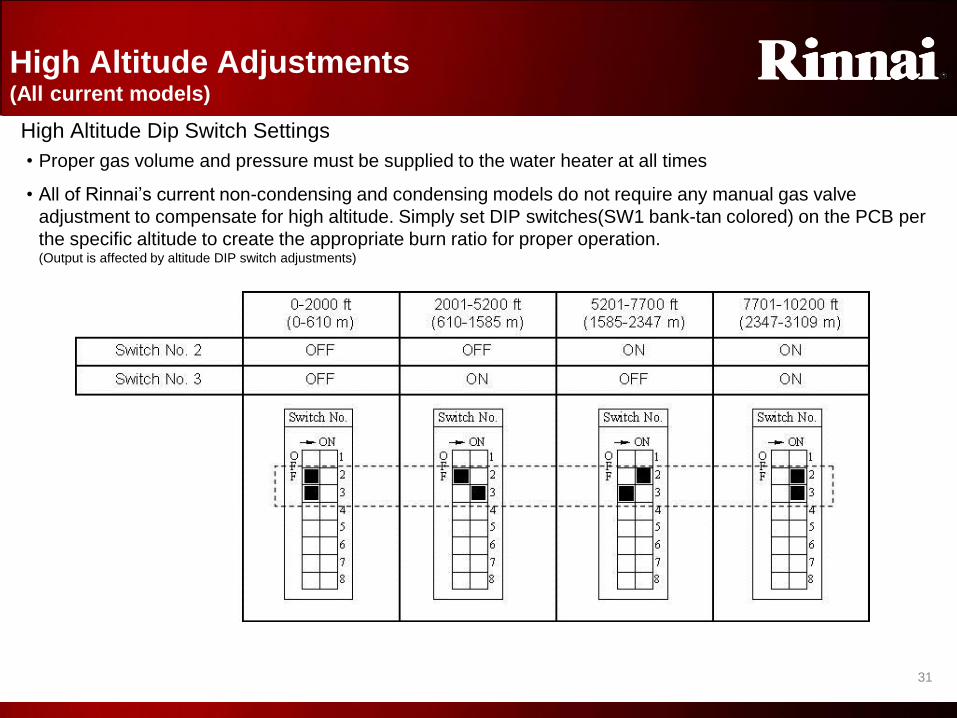
High Altitude Adjustments (All current models)
High Altitude Dip Switch Settings
• Proper gas volume and pressure must be supplied to the water heater at all times
• All of Rinnai’s current non-condensing and condensing models do not require any manual gas valve
adjustment to compensate for high altitude. Simply set DIP switches(SW1 bank-tan colored) on the PCB per
the specific altitude to create the appropriate burn ratio for proper operation. (Output is affected by altitude DIP switch adjustments)
High Altitude Adjustments

3
2
32
VENTING
REQUIREMENTS • It is imperative to ensure proper vent guidelines are
followed.
• Ensure non-condensing and condensing guidelines are understood.
• Do not mix vent parts or individual requirements between non-condensing and condensing models as dangerous safety conditions could occur!
! WARNING
Improper installation of vent system and components, or failure to follow all installation
instructions, can result in property damage or serious injury.
Venting Requirements
3
3
33
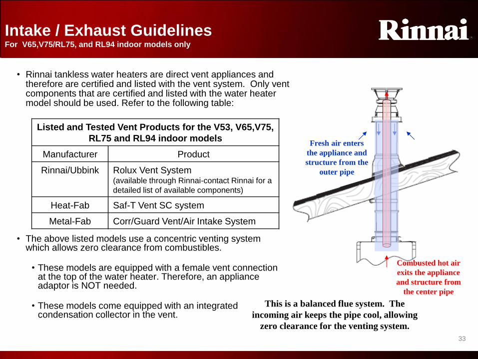
• The above listed models use a concentric venting system which allows zero clearance from combustibles.
• These models are equipped with a female vent connection at the top of the water heater. Therefore, an appliance adaptor is NOT needed.
• These models come equipped with an integrated condensation collector in the vent.
Combusted hot air
exits the appliance
and structure from
the center pipe
Fresh air enters
the appliance and
structure from the
outer pipe
This is a balanced flue system. The
incoming air keeps the pipe cool, allowing
zero clearance for the venting system.
• Rinnai tankless water heaters are direct vent appliances and therefore are certified and listed with the vent system. Only vent components that are certified and listed with the water heater model should be used. Refer to the following table:
Listed and Tested Vent Products for the V53, V65,V75,
RL75 and RL94 indoor models
Manufacturer Product
Rinnai/Ubbink Rolux Vent System (available through Rinnai-contact Rinnai for a
detailed list of available components)
Heat-Fab Saf-T Vent SC system
Metal-Fab Corr/Guard Vent/Air Intake System
Intake / Exhaust Guidelines For V65,V75/RL75, and RL94 indoor models only
Intake/Exhaust Guidelines

3
4
34
Indoor - Vent Length Calculator
(All current models)
Elbow Length Calculator
Each 90° bend is equivalent to 6 feet of vent pipe
= 6 Feet
Each 45° bend is equivalent to 3 feet of vent pipe
= 3 Feet
• Total equivalency cannot exceed 41 feet
• If the equivalency is greater than 21 feet, move DIP switch #1(bank of eight tan colored)
to OFF (this switch is shipped in the ON position)
• Comply with all vent guidelines – refer to vent manufacturer and installation instructions.
• The R94/RL94 indoor model’s maximum water flow capacity will be reduced by roughly 10% when DIP switch no. 1 is OFF.
• These images depict concentric venting. R98 models do not use concentric venting but use the same equivalency guidelines.
Add the total length of
all vent pipe and the
equivalency of all bends:
3’ (termination)
+3’ (bend)
+2’ (extension)
+3’ (bend)
+2’ (extension)
13 foot equivalency S
w
i
t
c
h
N
u
m
b
e
r
→ ON O
F
F
1
2
3
4
5
6
7
8
Vent Length Example
2 feet
2 feet
3 feet
45° bend = 3 feet
45° bend = 3 feet
In this example,
DIP switch #1
would remain in
the ON position
Vent Length Calculator

3
5
35
Vent Clearances – ANSI Standards (for all Rinnai Water Heaters)
See Chart on the following page for the ANSI recommended clearance of each corresponding letter
Vent Clearances
3
6
36
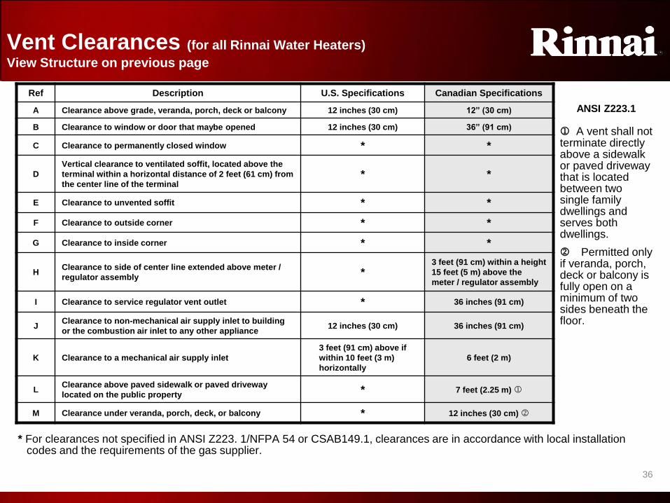
Vent Clearances (for all Rinnai Water Heaters)
View Structure on previous page
Ref Description U.S. Specifications Canadian Specifications
A Clearance above grade, veranda, porch, deck or balcony 12 inches (30 cm) 12” (30 cm)
B Clearance to window or door that maybe opened 12 inches (30 cm) 36” (91 cm)
C Clearance to permanently closed window * *
D
Vertical clearance to ventilated soffit, located above the
terminal within a horizontal distance of 2 feet (61 cm) from
the center line of the terminal * *
E Clearance to unvented soffit * *
F Clearance to outside corner * *
G Clearance to inside corner * *
H Clearance to side of center line extended above meter /
regulator assembly *
3 feet (91 cm) within a height
15 feet (5 m) above the
meter / regulator assembly
I Clearance to service regulator vent outlet * 36 inches (91 cm)
J Clearance to non-mechanical air supply inlet to building
or the combustion air inlet to any other appliance 12 inches (30 cm) 36 inches (91 cm)
K Clearance to a mechanical air supply inlet
3 feet (91 cm) above if
within 10 feet (3 m)
horizontally
6 feet (2 m)
L Clearance above paved sidewalk or paved driveway
located on the public property * 7 feet (2.25 m) j
M Clearance under veranda, porch, deck, or balcony * 12 inches (30 cm) k
j A vent shall not terminate directly above a sidewalk or paved driveway that is located between two single family dwellings and serves both dwellings.
k Permitted only if veranda, porch, deck or balcony is fully open on a minimum of two sides beneath the floor.
ANSI Z223.1
* For clearances not specified in ANSI Z223. 1/NFPA 54 or CSAB149.1, clearances are in accordance with local installation codes and the requirements of the gas supplier.
Vent Clearances

3
7
37
Rinnai Vent Termination Requirements (for all Rinnai Water Heaters)
• Avoid terminations near a dryer vent
• Avoid terminations near commercial cooking exhaust
• Comply with local and state codes as required
36” (.91 m) to ventilated or unventilated soffit or eve vent; or to a deck or porch
12” (.30 m) to an inside corner
12” (30 cm) between Rinnai terminals at the same level
The above clearances also apply to external models.
12” (30 cm) between Rinnai terminals at the same level
60” (1.52m) between Rinnai terminals at different levels
60” (1.52m) vertically between Rinnai terminals (Also applies to external models)
NOTE: It is acceptable to be within 60” vertically if a horizontal clearance of 12” is maintained
V Vent terminal represents concentric vent terminal or R98 LS series exhaust vent only or external exhaust where applicable
Vent Termination
3
8
38
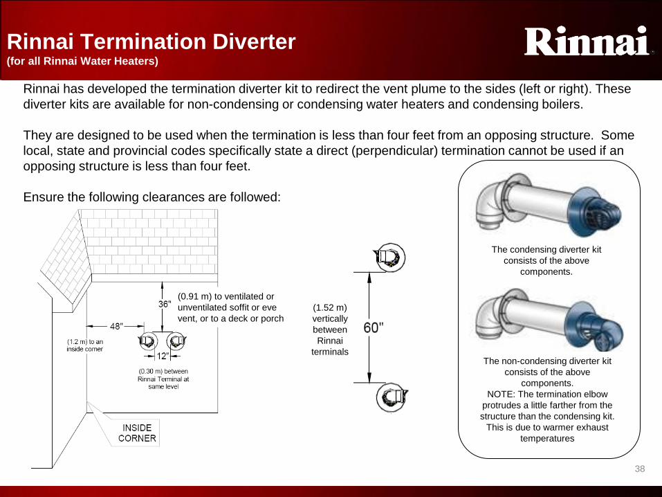
Rinnai Termination Diverter (for all Rinnai Water Heaters)
Rinnai has developed the termination diverter kit to redirect the vent plume to the sides (left or right). These
diverter kits are available for non-condensing or condensing water heaters and condensing boilers.
They are designed to be used when the termination is less than four feet from an opposing structure. Some
local, state and provincial codes specifically state a direct (perpendicular) termination cannot be used if an
opposing structure is less than four feet.
Ensure the following clearances are followed:
(0.91 m) to ventilated or
unventilated soffit or eve
vent, or to a deck or porch
(1.52 m)
vertically
between
Rinnai
terminals The non-condensing diverter kit
consists of the above
components.
NOTE: The termination elbow
protrudes a little farther from the
structure than the condensing kit.
This is due to warmer exhaust
temperatures
The condensing diverter kit
consists of the above
components.
Vent Termination Diverter

3
9
39
Cutting Ubbink Vent Pipe
• Certain applications require the vent pipe to be shortened to fit the application
• Shortening of Vent Pipe Extensions –
• The aluminum inside pipe should always extend 0.4 or 7/16” (10 mm) beyond the white outside of
the male end of the vent extension.
• Always cut the male end of the vent pipe extension. Do not attempt to cut the female end.
Improper installation of vent system and components, or failure to follow all
installation instructions, can result in property damage or serious injury.
0.4 or 7/16” (10mm)
Overall length = length of the outer pipe + 0.4 or 7/16”
Telescopic vent effective length is 2.2” – 12”
Intake / Exhaust Guidelines (For all Ubbink Pipe – aluminum or PP-s types)
• Ubbink also offers a telescopic vent extension that requires no cutting. This can reduce install time
and prevent possible vent sealing issues.
Cutting Ubbink Pipe

4
0
40
Draining Vent Condensation (Non-condensing models only)
Rubber Cap
• Condensation occurs when the water created in the combustion process cools below the dew point. As this water vapor condenses, it combines with other combustion by-products to form an acid solution. The resultant acid will collect and eventually destroy the joints and seams of any vent system not designed and or installed to properly drain the condensate solution.
• Condensate formation can occur in mid and high efficiency direct vent appliances.
• Even though many Rinnai tankless water heaters are referred to as “non-condensing” models,
condensation can still occur in the vent system
• Space provisions must be made to properly drain and dispose of the condensate.
• The condensate drain trap must contain a minimum of 3” of water.
• Dispose of condensate per local codes.
Rinnai products with a male appliance
top require a discharge adapter
Rinnai products with a female appliance top have an integrated condensate collector. Removal of the
rubber cap is required to connect the collector.
R98 LSi models (R)V53i, R75/RL75, and R94/RL94 indoor models
Rinnai now offers a self priming condensate trap that does not require
periodic priming
Draining Vent Condensation

4
1
41
Vent Termination For V65i, V75i/RL75i, and RL94 indoor models only
The diagrams illustrate the correct way to address condensation with Rinnai concentric vented water heaters ,V65, V75/RL75, RL94 indoor models only)
• The integrated condensate collector MUST BE used on all vertical vent terminations and on any horizontal vent termination where the vertical run exceeds 5 feet or two or more elbows exist.
• If the condensate collector is used in a horizontal vent termination, the exhaust venting MUST BE sloped 1/4" per foot towards the water heater.
• If no condensate collector is used in a horizontal vent termination the exhaust venting MUST BE sloped 1/4" per foot towards the exhaust terminal.
• The condensation trap MUST contain at least 3” of water
Vent Termination (indoor)

4
2
42
• Vent diameter must not be reduced
• Do not common vent with the vent pipe of any other water heater or appliance
Intake / Exhaust Guidelines (For all Ubbink Pipe – aluminum or PP-s types)
Do not combine vent components from
different manufacturers
The vent system must vent directly to the outside of the building with proper
termination clearances
• Only the black portion of the vertical termination should be exposed to the exterior.
• No Ubbink pipe joints should be exposed to the outside
Do not connect the venting system with an
existing vent or chimney
Do not use Class-B vent
Ubbink offers a paintable “snorkel” kit that will in many cases allow for a low structure termination while protecting all joints. This accessory is available for non-condensing or condensing models—the part number is different for each—ensure the correct part is used!
Intake/Exhaust Guidelines
4
3
43
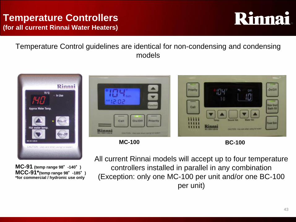
Temperature Controllers (for all current Rinnai Water Heaters)
MC-91 (temp range 98°-140°)
MCC-91*(temp range 98°-185°)
MC-100 BC-100
*for commercial / hydronic use only
All current Rinnai models will accept up to four temperature
controllers installed in parallel in any combination
(Exception: only one MC-100 per unit and/or one BC-100
per unit)
Temperature Control guidelines are identical for non-condensing and condensing
models
Temperature Controllers

4
4
44
When multiple controllers are
installed, the priority button
allows each to individually set
temperature output of the water
heater. The priority indicator
reports which controller has
control.
Indicates the selected
water temperature.
Diagnostic Codes flash if
operator intervention is
required.
ON/OFF BUTTON MODEL NUMBER
IN USE INDICATOR
Indicates that the unit is in
operation
TEMPERATURE
INDICATION
THERMOSTAT
Increases or decreases the
desired water temperature
PRIORITY BUTTON
& INDICATOR
MC-91/MCC-91 Temperature Controls (For all current Rinnai Water Heaters)
MC-91/MCC-91

4
5
45
MC-100/BC-100 Temperature Controllers (For all current Rinnai Water Heaters)
IN USE INDICATOR
Flame indicates unit is
in operation
TIME DISPLAY
CALL BUTTON
Pages (by beeping) all other
temperature controllers installed
on the same water heater
Sets time and
sound volume
FUNCTION
POWER SAVER
Turns display off after
extended non-use to
save energy
BATH FILL AND WATER VOLUME BUTTONS**
Bath fill allows a specific volume and temperature of
water to be programmed to fill a tub. Once that
amount of water is delivered, water heater will stop
hot water deliver.
• “Bath” will show on the BC-100 and MC-100 when
in use (see MC-100 picture).
• The fill amount and remaining fill volume will be
displayed as well
The MC-100 also has an extended diagnostic menu to aid in servicing. Contact Rinnai technical support for additional information. *Bath fill feature allows temperature adjustments from 98º F to 120º F. The BC-100 monitors flow through one water heater. DO NOT use this feature in applications with two or more water heaters. Do not use with single handled fixtures. Use only hot water when using the BC-100 controller.
Also available on BC-100
MC-100
BC-100
MC-100 and BC-100 controllers have the same features and the MC-91 plus these additional benefits:
MC-100/BC-100

4
6
46
• All water heaters* manufactured July, 2008 or after have the following
temperature adjustment features:
• Maximum default production temperature setting of 120º F (49º C)
Temperature Controller Range (for all current Rinnai Water Heaters)
S
w
i
t
c
h
N
u
m
b
e
r
→ ON
O
F
F
1
2
3
4
5
6
7
8
• Meets requirements of various
local codes
• Enhances safety of users,
especially children and the elderly
• Temperatures between 125 – 140º
(52º - 60ºC) are available by setting
DIP switch 6 to the ON position in
the SW1 bank of 8 (tan colored)
DIP switches
*The V53e does not default at a max
of 120°F with an MC-91 (or similar
controller). These models will always
max at 140°F. DIP switch 6 is
allocated for another use.
Temperature Controller Range

4
7
47
Temperature controller connection
• Refer to owner’s / installation manual of each model for specific installation
instructions
• Controller wires are to be connected to the unit where indicated . Wires are
not polarity sensitive.
• Indoor models come with a temperature controller integrated into the front
cover and its wiring already connected.
• Outdoor models come with an independent temperature controller to be
installed remotely.
• Controllers operate on 12 VDC supplied from the PCB and should never be
connected to supply voltage (120 VAC)
• Controllers can be located anywhere in the structure protected from heat,
direct sunlight, water, and small children
• Standard thermostat wire can be used to connect the controller to the water
heater if needed
• When connecting multiple controllers, they must be wired in parallel:
Rinnai®
Tankless Water Heater
Controllers Rinnai®
Tankless Water Heater
Controllers
Parallel Connection (correct) Series Connection (incorrect!)
Temperature Controller Installation (for all current Rinnai Water Heaters)
*The connection for
temperature controllers
for the V53e is located
on the bottom of the
cabinet
Temperature Controller Install
4
8
48
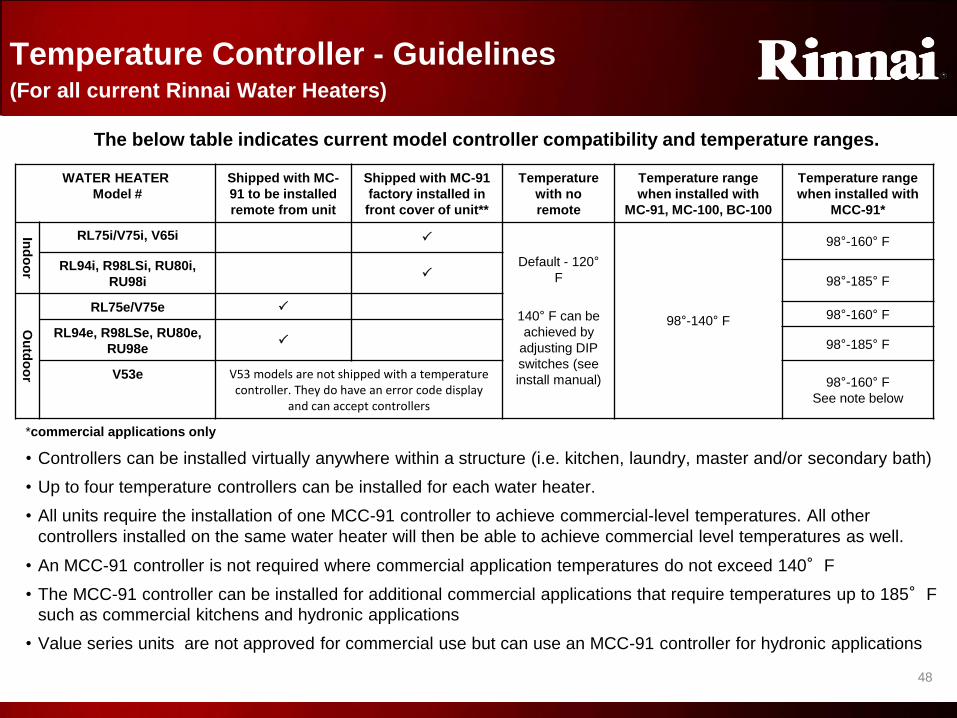
Temperature Controller - Guidelines (For all current Rinnai Water Heaters)
WATER HEATER
Model #
Shipped with MC-
91 to be installed
remote from unit
Shipped with MC-91
factory installed in
front cover of unit**
Temperature
with no
remote
Temperature range
when installed with
MC-91, MC-100, BC-100
Temperature range
when installed with
MCC-91*
Ind
oo
r
RL75i/V75i, V65i P
Default - 120°
F
140° F can be
achieved by
adjusting DIP
switches (see
install manual)
98°-140° F
98°-160° F
RL94i, R98LSi, RU80i,
RU98i P
98°-185° F
Ou
tdo
or
RL75e/V75e P 98°-160° F
RL94e, R98LSe, RU80e,
RU98e P 98°-185° F
V53e
V53 models are not shipped with a temperature controller. They do have an error code display
and can accept controllers
98°-160° F
See note below
The below table indicates current model controller compatibility and temperature ranges.
*commercial applications only
• Controllers can be installed virtually anywhere within a structure (i.e. kitchen, laundry, master and/or secondary bath)
• Up to four temperature controllers can be installed for each water heater.
• All units require the installation of one MCC-91 controller to achieve commercial-level temperatures. All other
controllers installed on the same water heater will then be able to achieve commercial level temperatures as well.
• An MCC-91 controller is not required where commercial application temperatures do not exceed 140°F
• The MCC-91 controller can be installed for additional commercial applications that require temperatures up to 185°F
such as commercial kitchens and hydronic applications
• Value series units are not approved for commercial use but can use an MCC-91 controller for hydronic applications
Temperature Controller Guidelines
4
9
49
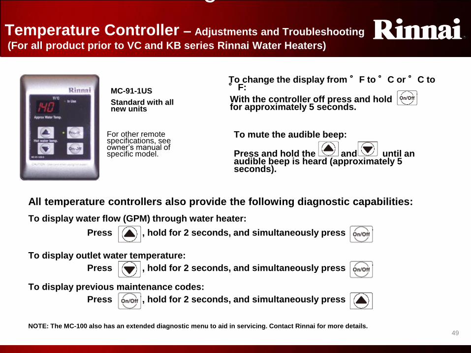
For other remote specifications, see owner’s manual of specific model.
All temperature controllers also provide the following diagnostic capabilities:
To display water flow (GPM) through water heater:
Press , hold for 2 seconds, and simultaneously press
To display outlet water temperature:
To display previous maintenance codes:
MC-91-1US
Standard with all new units
To change the display from °F to °C or °C to °F:
With the controller off press and hold for approximately 5 seconds.
To mute the audible beep:
Press and hold the and until an audible beep is heard (approximately 5 seconds).
Press , hold for 2 seconds, and simultaneously press
Press , hold for 2 seconds, and simultaneously press
NOTE: The MC-100 also has an extended diagnostic menu to aid in servicing. Contact Rinnai for more details.
Temperature Controller – Adjustments and Troubleshooting
(For all product prior to VC and KB series Rinnai Water Heaters)
Temperature Controller
Troubleshooting

5
0
50
• MC-91-1 and MCC-91-1 changing to MC-91-2 and MCC-91-2
• MC-91-2/MCC-91-2 controllers are backwards compatible
• An additional table of temperature increments is available (“alternate temperature settings”)
• For commercial applications ONLY
• Intended to provide additional increments between 140°F and 185°F
• These can only be accessed with the new “-2” controllers
• Controller now has locking function and increased diagnostics capability.
• Controller in interior units can NOT be removed and used as a remote control.
• Relocation kits no longer necessary
Controller Changes
Controller Changes
5
1
51
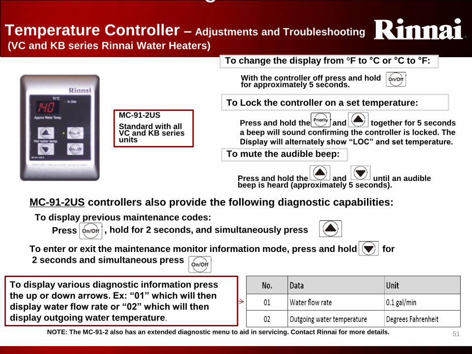
MC-91-2US controllers also provide the following diagnostic capabilities:
To display previous maintenance codes:
MC-91-2US
Standard with all VC and KB series units
To change the display from °F to °C or °C to °F:
With the controller off press and hold for approximately 5 seconds.
To mute the audible beep:
Press and hold the and until an audible beep is heard (approximately 5 seconds).
Press , hold for 2 seconds, and simultaneously press
Temperature Controller – Adjustments and Troubleshooting
(VC and KB series Rinnai Water Heaters)
Press and hold the and together for 5 seconds
a beep will sound confirming the controller is locked. The
Display will alternately show “LOC” and set temperature.
To Lock the controller on a set temperature:
To enter or exit the maintenance monitor information mode, press and hold for
2 seconds and simultaneous press
To display various diagnostic information press
the up or down arrows. Ex: “01” which will then
display water flow rate or “02” which will then
display outgoing water temperature.
NOTE: The MC-91-2 also has an extended diagnostic menu to aid in servicing. Contact Rinnai for more details.
Temperature Controlller
Troubleshooting

5
2
52
New Alternate Temperature Settings
1/23/2017 52
New
settings
Note: SW2 bank
of dip switches
(white) on some
units will have a
bank of 8
A different range of temperature setting is available by setting switches 2 and 3 of the SW2 dip switch
(white switches) to on. The table below shows the settings available with the MC-91-2 and MCC-91-2.

5
3
53
Temperature Controller - MC-91 Relocation Kit
(Not used for VC or KB series Water Heaters)
If an indoor water heater (with the MC-91
integrated in the front cover) is placed in an
inaccessible location, like an attic or crawl space,
the installer could use this kit to remove the MC-
91 from the front panel and relocate it to a remote
location.
• This kit fills the hole left after relocating the
working controller
• The working MC-91 controller assembly lacks an
outer trim piece (bezel) and so requires that the
bezel that comes with the kit be snapped on to
make it look like a complete unit.
• Accessory part number: MC-91-1US-S-RK
Blanking Plate
(non-functioning controller
Installed in place of
controller
Bezel
Remote Controller –
available for
relocation
Integrated
Controller
removed
Temperature Controller Relocation
5
4
54
WARRANTY
&
MAINTENANCE
Warranty and Maintenance

5
5
55
KEY POINTS OF LIMITED WARRANTY COVERAGE (all models)
• **Labor: 5 years residential / 2 years commercial for RL / RU / R98LS models when registered within 30 days of installation, 1 year all other applications and models, *** Heat exchanger warranty increased from 10 to 12 years if a isolation valve kit is installed on Value series.
• 3-year heat exchanger and parts warranty when water heater is installed in a circulation loop or system, or in a series where all water flows through the water heater, and where an on demand system is not incorporated.
• Note: The Rinnai warranty for a condensing model heat exchanger used in a circulation system which is controlled through an aquastat / thermostat, or timer, or an on-demand system is 12 years for residential applications.
• If a Rinnai water heater is used in a commercial application, the commercial warranty will apply. Exception: V53,V65, and V75 models are not approved for commercial applications
• If a Rinnai tankless water heater is in conjunction with a Rinnai Hydronic Furnace, the heat exchanger is warranted for 10 years and all other parts are warranted for 5 years. Heat Exchanger coverage is reduced to 5 years from date of purchase if the Rinnai water heater temperature setting exceeds 160ºF (71ºC).
• Warranty covers any defects in materials or workmanship when the product is installed and operated according to Rinnai written installation instructions
• Warranty applies only to products that are installed per local and/or state codes. Improper installation may void the warranty.
• Warranty doesn’t cover failure due to accident, abuse, misuse, alteration, misapplication, force majeure, improper installation, maintenance, or service, inadequate water quality, scale buildup, or freeze damage
• Warranty doesn’t cover any product used as a pool or spa heater. Warranty does cover bathroom whirlpool tubs.
• Warranty does not cover product or component failures where the water supply does not meet the National Secondary Drinking Water Regulations.
Warranty-All Models*
Residential Commercial
Heat Exchanger Parts **Labor Heat Exchanger Parts **Labor
12 or 10 (model dependent)
5 5 5 5 2
V53e, V65i/e, and V75i/e models have a 10 year heat exchanger ***and 1 year Labor warranty* / all other models have a 12
year heat exchanger warranty. Previous model warranties may vary *See Owner’s manual for complete warranty guidelines
Warranty

5
6
56
Maintenance – Inlet Water Filter (All Rinnai Models )
• Rinnai recommends that the inlet water filter be cleaned before the initial operation of a new unit.
• Before removing the inlet filter, ensure that the water supply has been turned off, and all pressure in the hot water system has been drained off by opening a hot water tap to ensure no water is flowing.
• See filter location in picture at right.
• The filter assembly should be hand tightened only.
Inlet Filter Screen
Maintenance-Inlet Water Filter

5
7
57
Maintenance – Service Flush Procedure (All Rinnai Models )
1. Disconnect electrical power to the water heater
2. Close the shutoff valves on both the hot and cold water lines (V3 and V4)
3. Connect pump outlet hose (H1) to the cold water line at service valve V2
4. Connect drain hose (H3) to service valve V1
5. Pour approximately 4 gallons of virgin food grade white vinegar or citric acid into pail
6. Place the drain hose (H3) and the hose (H2) to the pump inlet into the cleaning solution
7. Open both service valves (V1 and V2) on the hot and cold water lines
8. Operate the pump and allow the cleaning solution to circulate through the water heater for at least 45 minutes
9. Turn off the pump
10. Rinse the cleaning solution from the water heater by:
a. Remove the free end of the drain hose (H3) from the pail and place in a suitable drain
b. Close service valve, V2, and open shutoff valve, V4. Do not open shutoff valve, V3.
c. Allow water to flow through the water heater for 5 minutes
d. Close service valve, V1, and open shutoff valve, V3
11. Disconnect all hoses
12. Remove the in-line filter at the cold water inlet and clean out any residue
a. Place the filter back into the unit
13. Restore electrical power to the water heater
For proper operation, unit longevity, and warranty adherence, water
supply to the water heater must meet National Secondary Drinking
Water Regulations. In areas with hard water, a water softener or other
conditioning may be needed. A periodic flushing procedure may also
be required. Below is the proper flushing procedure:
Maintenance-Flush
5
8
58
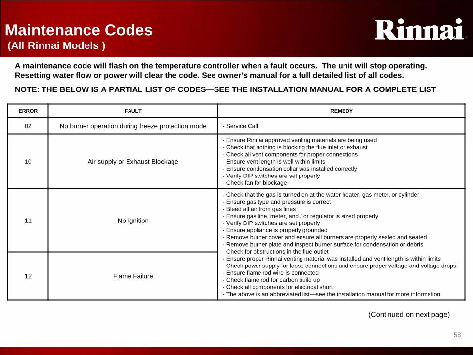
Maintenance Codes (All Rinnai Models )
A maintenance code will flash on the temperature controller when a fault occurs. The unit will stop operating.
Resetting water flow or power will clear the code. See owner's manual for a full detailed list of all codes.
NOTE: THE BELOW IS A PARTIAL LIST OF CODES—SEE THE INSTALLATION MANUAL FOR A COMPLETE LIST
ERROR FAULT REMEDY
02 No burner operation during freeze protection mode - Service Call
10 Air supply or Exhaust Blockage
- Ensure Rinnai approved venting materials are being used
- Check that nothing is blocking the flue inlet or exhaust
- Check all vent components for proper connections
- Ensure vent length is well within limits
- Ensure condensation collar was installed correctly
- Verify DIP switches are set properly
- Check fan for blockage
11 No Ignition
- Check that the gas is turned on at the water heater, gas meter, or cylinder
- Ensure gas type and pressure is correct
- Bleed all air from gas lines
- Ensure gas line, meter, and / or regulator is sized properly
- Verify DIP switches are set properly
- Ensure appliance is properly grounded
- Remove burner cover and ensure all burners are properly sealed and seated
- Remove burner plate and inspect burner surface for condensation or debris
- Check for obstructions in the flue outlet
- Ensure proper Rinnai venting material was installed and vent length is within limits
- Check power supply for loose connections and ensure proper voltage and voltage drops
- Ensure flame rod wire is connected
- Check flame rod for carbon build up
- Check all components for electrical short
- The above is an abbreviated list—see the installation manual for more information
12 Flame Failure
(Continued on next page)
Maintenance Codes
5
9
59
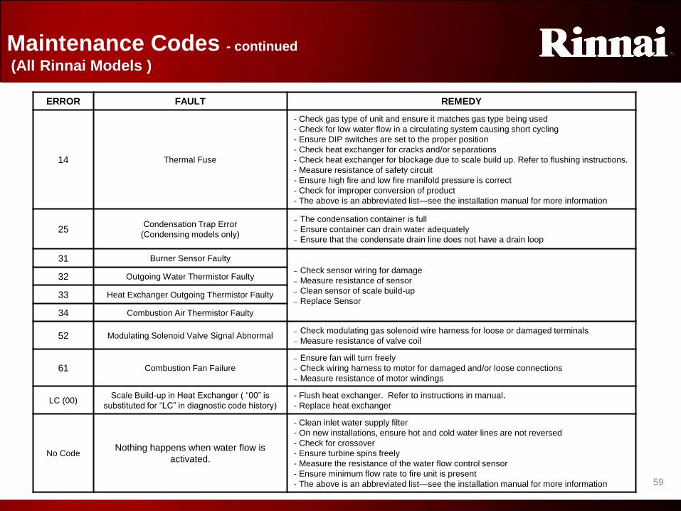
ERROR FAULT REMEDY
14 Thermal Fuse
- Check gas type of unit and ensure it matches gas type being used
- Check for low water flow in a circulating system causing short cycling
- Ensure DIP switches are set to the proper position
- Check heat exchanger for cracks and/or separations
- Check heat exchanger for blockage due to scale build up. Refer to flushing instructions.
- Measure resistance of safety circuit
- Ensure high fire and low fire manifold pressure is correct
- Check for improper conversion of product
- The above is an abbreviated list—see the installation manual for more information
25 Condensation Trap Error
(Condensing models only)
– The condensation container is full
– Ensure container can drain water adequately
– Ensure that the condensate drain line does not have a drain loop
31 Burner Sensor Faulty
– Check sensor wiring for damage
– Measure resistance of sensor
– Clean sensor of scale build-up
– Replace Sensor
32 Outgoing Water Thermistor Faulty
33 Heat Exchanger Outgoing Thermistor Faulty
34 Combustion Air Thermistor Faulty
52 Modulating Solenoid Valve Signal Abnormal – Check modulating gas solenoid wire harness for loose or damaged terminals
– Measure resistance of valve coil
61 Combustion Fan Failure
– Ensure fan will turn freely
– Check wiring harness to motor for damaged and/or loose connections
– Measure resistance of motor windings
LC (00) Scale Build-up in Heat Exchanger ( “00” is
substituted for “LC” in diagnostic code history)
- Flush heat exchanger. Refer to instructions in manual.
- Replace heat exchanger
No Code Nothing happens when water flow is
activated.
- Clean inlet water supply filter
- On new installations, ensure hot and cold water lines are not reversed
- Check for crossover
- Ensure turbine spins freely
- Measure the resistance of the water flow control sensor
- Ensure minimum flow rate to fire unit is present
- The above is an abbreviated list—see the installation manual for more information
Maintenance Codes - continued
(All Rinnai Models )
Maintenance Codes

6
0
60
VARIOUS
INSTALLATION DRAWINGS
Rinnai’s Engineering / Application department is available for assistance in sizing residential and commercial projects. Please call 1-800-621-9419.
• DO NOT use the following drawings for piping systems. These are only intended to be used as examples, and may not include all the components needed for all applications.
• For additional drawings and sizing information please review the Rinnai Hot Water System Design Manual available or Rinnai’s sizing calculators available at www.rinnai.us or by calling 1-800-621-9419.
• It is the engineer / contractors responsibility to ensure that installation is in accordance with all local and state building codes. Confer with your local building officials before installation.
Installation Drawings

6
1
61
Piping – Standard Installation
Gas Supply
3/4” Hot Water Supply Line 3/4” Cold Water Supply Line
Example Drawing Only
Standard Installation
• Single Unit based on structure’s hot water demand (bathrooms / fixtures)
Piping Standard Install
6
2
62
Piping – Multi Unit Application
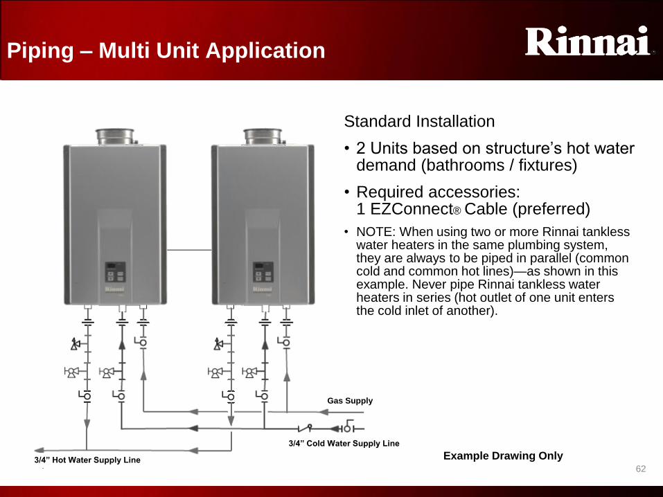
Standard Installation
• 2 Units based on structure’s hot water demand (bathrooms / fixtures)
• Required accessories: 1 EZConnect® Cable (preferred)
• NOTE: When using two or more Rinnai tankless water heaters in the same plumbing system, they are always to be piped in parallel (common cold and common hot lines)—as shown in this example. Never pipe Rinnai tankless water heaters in series (hot outlet of one unit enters the cold inlet of another).
Example Drawing Only
Gas Supply
3/4” Hot Water Supply Line
3/4” Cold Water Supply Line
Piping Multi Unit

6
3
63
Recommended Piping-Recirculation
Minimum ¾” Hot
Water Supply Line
Important
Install return line to the
hot supply as close as
possible to the Rinnai
water heater
Expansion Tank
Building Supply
Minimum ¾” Cold
Water Supply Line
Gas Supply
For this application
• Pump should be controlled by an Aquastat, Timer, or combination
Aquastat and Timer.
• Pump to be sized to maintain circulation loop temperature.
• The pump should be sized to overcome the pressure loss through
the tank water heater and supply and return plumbing in the
circulation loop. See the latest release of Rinnai’s Hot Water
System Design Manual for more information.
• Pump to be of bronze or stainless construction.
Gas or
Electric
Tank Water
Heater
Example Drawing Only
Piping Recirculation

6
4
64
Optional Piping-Recirculation
IMPORTANT
• Recirculation line must be a minimum
¾” piping throughout
• Warranty on the heat exchanger and
all parts is reduced to three years with
this option, unless an on demand
circulation system is installed.
• An On-Demand recirculation system
consists of switches or motion sensors
activated by user intervention to
control the cycling time and circulation
time of hot water throughout the
plumbing system.
For this application
• Pump should be controlled by an
Aquastat, Timer, or combination
Aquastat and Timer.
• Pump to be sized to maintain
circulation loop temperature.
• A minimum of 3 GPM flow is
recommended for the circulation system.
• The pump should be sized to
overcome the pressure loss through
the Rinnai, storage tank and supply and
return plumbing in the circulation loop.
See the latest release of Rinnai’s Hot
Water System Design Manual for more
information.
• Pump to be of bronze or stainless
construction.
Minimum ¾” Hot
Water Supply Line Minimum ¾” Cold
Water Supply Line
Gas Supply
Expansion Tank Aquastat Connection
(Optional)
2-6 Gallon Storage Tank
(To eliminate cold water
sandwich effect caused by
frequent On/Off operation)
Building Outlets Example Drawing Only
Piping Recirculation (alt)

6
5 65
Building Outlets Smaller Return Line Can
be used after the last fixture
(Optional) Header Sized One Pipe Size Larger Than
Hot Water Supply Line – (To eliminate cold water
sandwich effect caused by frequent On-Off operation
Circulation System
Example Drawing Only
*Refer To Rinnai Accessories and
Model Applicability for electronic
connection details
Rinnai
Equipment List Qty
Rinnai Water Heaters 3
Electronic Connection *
For this application:
Pump should be controlled by an
Aquastat. Timer or Combination
Aquastat and Timer.
Pump to be sized to maintain circulation
loop temperature.
The pump should be sized to overcome
the pressure loss through the tank water
heater, and supply and return plumbing in
the circulation loop. Reference the
section Pump Sizing for Circulation.
Gas Supply
Cold Water Supply Line
Hot Water Supply Line
Aquastat Connection
Expansion Tank
Pump to be of
bronze of stainless
construction.
PVA to be kept on
factory default
setting
Circulation Unit
should not be
connected
electronically
Circulation System

6
6
66
Backup Storage / Circulation
Example Drawing Only
Expansion Tank
Storage Tank Gas Supply
Cold Water Supply Line
Building Hot
Water Return
Line
Building
Circulation
Pump
Building Hot
Water Supply
Line
(No Burner or
Heating Element)
Submersible
Aquastat (set @
20° F below
Rinnai
Temperature
Setting)
Pump / Aquastat Control Wire
Reference the section on
Pump Sizing for Storage
Tank Application.
Set water heaters @ 20° F
above tank Aquastat
Backup Storage
6
7
67
Commercial Dishwasher Installations
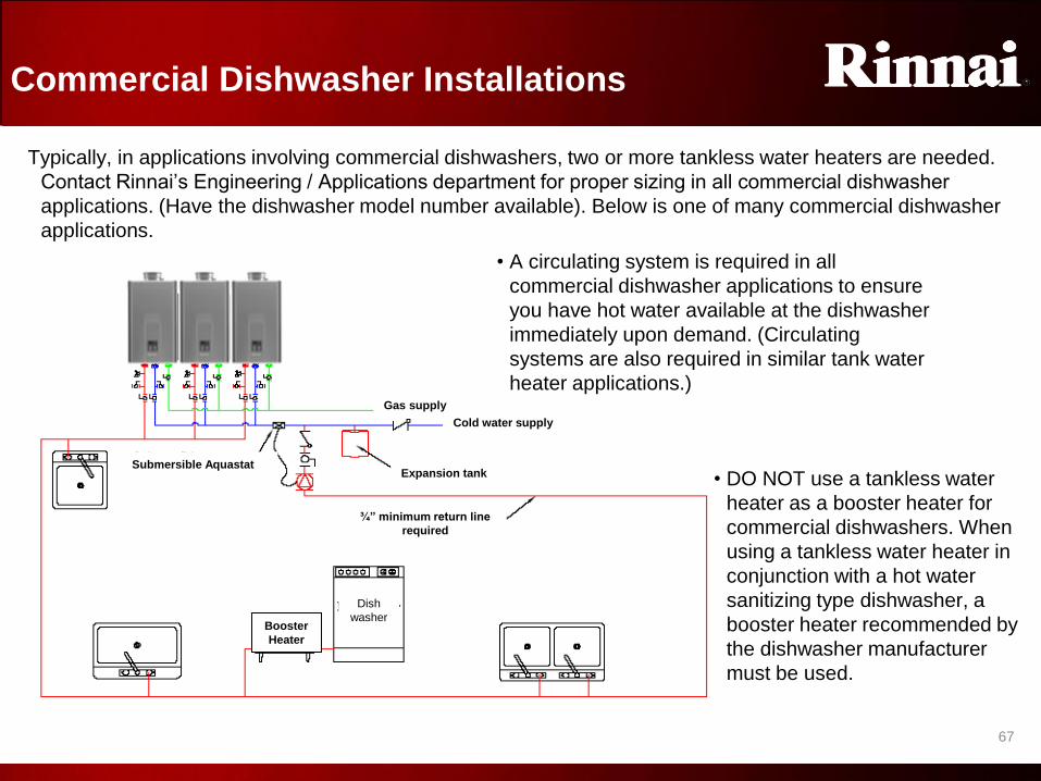
Typically, in applications involving commercial dishwashers, two or more tankless water heaters are needed.
Contact Rinnai’s Engineering / Applications department for proper sizing in all commercial dishwasher
applications. (Have the dishwasher model number available). Below is one of many commercial dishwasher
applications.
• DO NOT use a tankless water
heater as a booster heater for
commercial dishwashers. When
using a tankless water heater in
conjunction with a hot water
sanitizing type dishwasher, a
booster heater recommended by
the dishwasher manufacturer
must be used.
Submersible Aquastat
¾” minimum return line
required
Expansion tank
Cold water supply
Gas supply
Dish
washer Booster
Heater
• A circulating system is required in all
commercial dishwasher applications to ensure
you have hot water available at the dishwasher
immediately upon demand. (Circulating
systems are also required in similar tank water
heater applications.)
Commercial Dishwasher
6
8
68
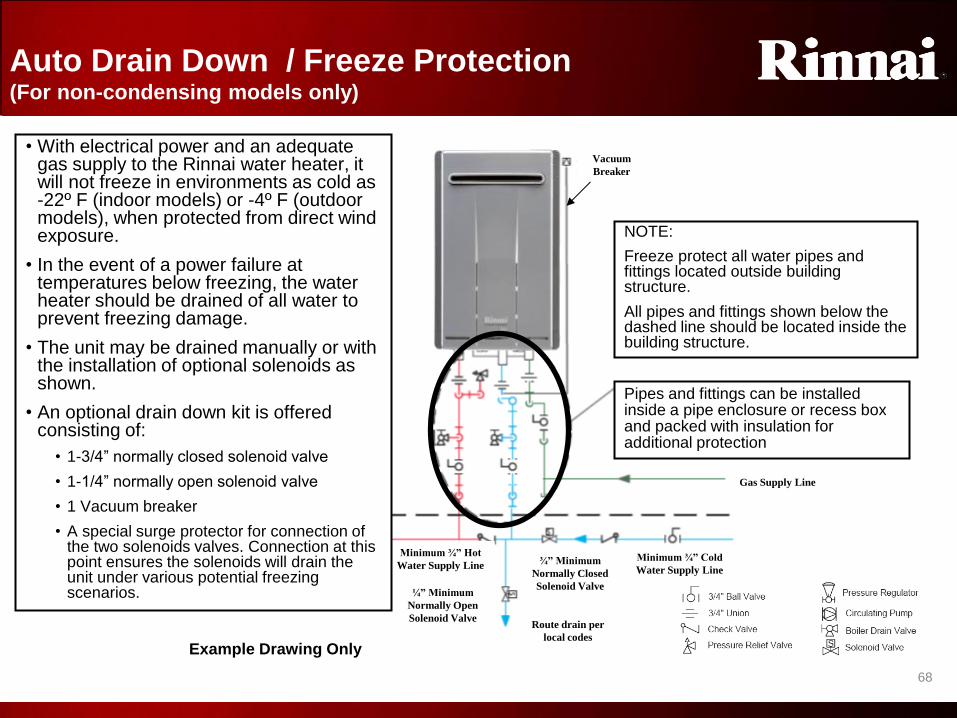
Auto Drain Down / Freeze Protection (For non-condensing models only)
Pipes and fittings can be installed inside a pipe enclosure or recess box and packed with insulation for additional protection
NOTE:
Freeze protect all water pipes and fittings located outside building structure.
All pipes and fittings shown below the dashed line should be located inside the building structure.
Minimum ¾” Hot
Water Supply Line
¼” Minimum
Normally Open
Solenoid Valve
¾” Minimum
Normally Closed
Solenoid Valve
Route drain per
local codes
Minimum ¾” Cold
Water Supply Line
Vacuum
Breaker
Gas Supply Line
Example Drawing Only
• With electrical power and an adequate gas supply to the Rinnai water heater, it will not freeze in environments as cold as -22º F (indoor models) or -4º F (outdoor models), when protected from direct wind exposure.
• In the event of a power failure at temperatures below freezing, the water heater should be drained of all water to prevent freezing damage.
• The unit may be drained manually or with the installation of optional solenoids as shown.
• An optional drain down kit is offered consisting of:
• 1-3/4” normally closed solenoid valve
• 1-1/4” normally open solenoid valve
• 1 Vacuum breaker
• A special surge protector for connection of the two solenoids valves. Connection at this point ensures the solenoids will drain the unit under various potential freezing scenarios.
Freeze Protection

6
9
69
Rinnai Condensing
Water Heater
Installation Differences
The following highlights the differences of condensing models
as compared to non-condensing models.
Please read each model’s installation manual that comes with each product.
Failure to comply with each model’s accompanying guidelines could void the warranty.
Installation Differences

7
0
70
DIFFERENCES
• Energy Factor rating as high as .96 (model dependent)
• Higher EF ratings could allow for additional rebate and tax incentives
• Integrated condensation trap—no need to address condensation in the vent system
• Draining direct to a drain system is permitted (check local codes-neutralizer may be required)
• Listed vent systems are different than Rinnai’s non-condensing water heaters
• Ubbink PP-s venting is economical and easy to install
• Ubbink PP-s has a plastic outer (intake) pipe and a flame-retardant polypropylene inner (exhaust) pipe
• Stainless steel secondary (latent) heat exchanger (primary heat exchanger is copper)
Condensing Model Product Features Similarities and differences compared to Rinnai’s non-condensing products
SIMILARITIES
• Energy Star Qualified—Eligible for various utility and tax incentives
• Industry leading activation rate of 0.4 gpm and lower minimum gas input rate of 10,000 Btu
• This allows ignition for smaller amounts of water at higher incoming temperatures
• Water flow deactivation is less than 0.26 gpm
• Current Rinnai temperature controllers are used with the condensing series
• Diagnostic codes are displayed on the controller—simplifying service issues
• Venting clearances and equivalencies are similar to Rinnai’s non-condensing water heaters
• Rinnai condensing water heaters are approved for installations up to 10,200 feet
• The same altitude setting procedures exist for condensing models
• Whole House continuous hot water system when properly sized
Condensing Features
7
1
71
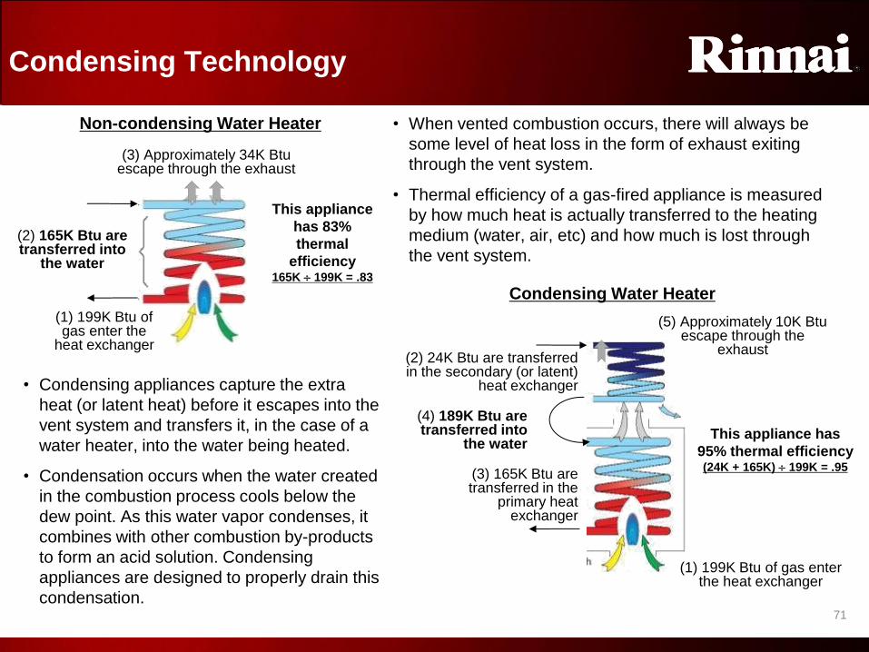
Condensing Technology
• When vented combustion occurs, there will always be
some level of heat loss in the form of exhaust exiting
through the vent system.
• Thermal efficiency of a gas-fired appliance is measured
by how much heat is actually transferred to the heating
medium (water, air, etc) and how much is lost through
the vent system.
(2) 165K Btu are transferred into
the water
(3) Approximately 34K Btu escape through the exhaust
This appliance
has 83%
thermal
efficiency 165K 199K = .83
• Condensing appliances capture the extra
heat (or latent heat) before it escapes into the
vent system and transfers it, in the case of a
water heater, into the water being heated.
• Condensation occurs when the water created
in the combustion process cools below the
dew point. As this water vapor condenses, it
combines with other combustion by-products
to form an acid solution. Condensing
appliances are designed to properly drain this
condensation.
(3) 165K Btu are transferred in the
primary heat exchanger
(1) 199K Btu of gas enter the heat exchanger
(4) 189K Btu are transferred into
the water
(2) 24K Btu are transferred in the secondary (or latent)
heat exchanger
(5) Approximately 10K Btu escape through the
exhaust
This appliance has
95% thermal efficiency
(24K + 165K) 199K = .95
(1) 199K Btu of gas enter the
heat exchanger
Non-condensing Water Heater
Condensing Water Heater
Condensing Technology

7
2
72
Condensing Technology
The RU98 and RU80 /KB series Condensing Units now have
a down-fired ceramic burner (with a downward-burning
flame)
This allows condensation to drain from the bottom of the
heat exchanger, providing greater longevity.
Condensate will drain down from secondary HEX, protecting primary HEX and burner. Condensate will drain down
from secondary HEX,
protecting primary HEX and
burner.
KB Condensing Units
Condensing Technology

7
3
73
Bypass
FR
SV1 SV2 SV3
Igniter
TC Sensor
Primary Heat Exchanger
PC
B /
Su
rge
Pro
tecto
r
Secondary Heat Exchanger
Con
de
nsa
te
Tra
p
Combustion
Fan
Incoming Air Exhaust
Water flow
control valve
Modulating
Gas Valve/POV
Water Flow
Sensor
Out going
Temperature
Thermistor
Heat
Exchanger
Thermistor
SV0 or SV
Main
1. Water flow begins • Water flow sensor sends pulses to the PCB
• When flow exceeds approximately 0.4 gpm the ignition sequence begins
2. Ignition Sequence
• Combustion fan turns to allow correct air flow thru unit
• Spark igniter begins sparking
• Gas control assembly opens to low fire rate
• When flame rod (FR) proves ignition, spark igniter stops sparking
3. Normal Operation
• Gas valve assembly & fan speed modulate gas and air input to meet user demand
• PCB monitors flame rod, TC Sensor, flame characteristic, fan motor frequency, outlet water temperature, temperature set point, and water flow rate
• If demand is very small, only SV1 will allow gas to burner. The flame rod (FR) will monitor this minimum fire state
• If demand is large, flame can develop across the entire burner
• Water is preheated in the secondary (latent) heat exchanger
• Water is heated as it passes through the heat exchanger multiple times
• Heat exchanger strategically overheats water while the variable bypass cools to the set point temperature to provide higher flow rates
• Condensation is drained through the condensation trap and to a drain
• Water flow control valve is adjusted, as needed
4. Shut-down Sequence • PCB senses flow rate less than 0.26 gpm
• Gas control valve closes & water flow control valve resets to standby position
• Combustion fan runs for a short period of time at low speed
5. Standby Mode • PCB monitors all components. Freeze protection is activated as needed
Sequence of Operation (indoor KB condensing unit)
Sequence of Operation (KB)

7
4
74
Intake / Exhaust Guidelines (For condensing models only)
• Refer to the vent pipe manufacturers’ instructions for component assembly instructions.
• Rinnai indoor condensing water heaters are direct vent water heaters and therefore are certified and listed with the vent system. Only vent components that are certified and listed with the water heater model should be used. Refer to the table below:
• The above listed vent systems use gaskets to ensure all seals are secure—no gluing or
cure time is required
• Schedule 40 PVC/CPVC venting is not approved and should never be used on exhaust
with Rinnai condensing water heaters
• Ubbink aluminum concentric venting is not approved for use with Rinnai condensing
water heaters • Ensure non-condensing and condensing guidelines are understood
• Do not mix vent parts or individual requirements between non-condensing and condensing models
as dangerous safety conditions could occur!
Listed and Tested Vent Products for the R80i and R98i
Manufacturer Product Description
Rinnai/Ubbink Rolux Condensing Vent System Polypropylene (PP-s)
Centrotherm InnoFlue Vent System Single wall 3”PP-s
Selkirk / Heat-Fab Saf-T Vent SC system AL29-4C Stainless Steel
Metal-Fab Corr/Guard Vent/Air Intake System
Intake/Exhaust Guidelines

7
5
75
Slope any horizontal venting toward the
water heater per venting manufacturer’s
installation instructions. Dispose of
condensate per local code
Slope any horizontal
venting toward the
water heater per
venting manufacturer’s
installation instructions.
Dispose of condensate
per local code.
Slope any horizontal venting toward
the water heater per the venting
manufacturer’s installation
instructions
• Rinnai / Ubbink PP-s venting for
condensing water heaters require a
¾” per foot slope
• Since there is an integrated
condensation trap inside the water
heater, no condensation collector in
the vent system is needed
¾” slope toward water heater when using
Ubbink PP-s condensing to ensure proper
flow through venting joints
¾” slope to water heater
Intake / Exhaust Guidelines (For condensing models only)
Intake/Exhaust Guidelines

7
6
76
Condensing label
on the packaging
Warning label on each individual vent piece
Condensing Concentric Venting Parts (For Condensing models only)
When purchasing or using Rinnai/Ubbink venting, ensure the proper type is used
• Rinnai/Ubbink polypropylene (PP-s) venting will have a green “Condensing” label on each package
• Each Rinnai/Ubbink PP-s condensing vent component will have an orange Warning Label on every
inside and outside piece
Inside pipe-
Exhaust
Outside pipe-
Intake
Condensing Venting

7
7
77
Centrotherm InnoFlue® 2 Pipe System
Innoflue Pipe
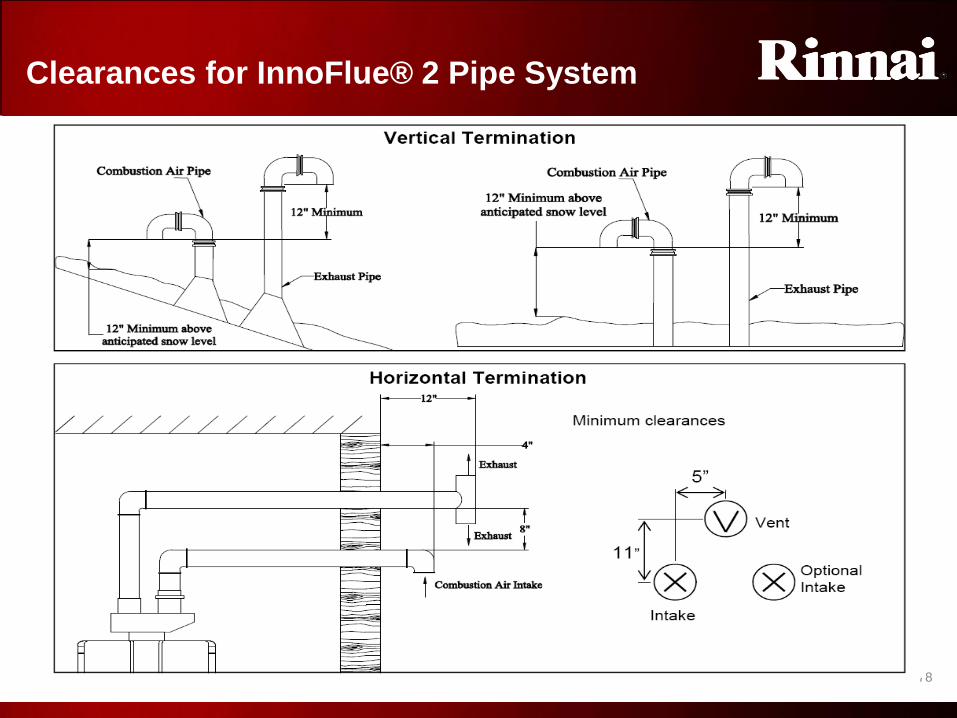
7
8
78
Clearances for InnoFlue® 2 Pipe System
Innoflue Clearances

7
9
79
Vent Length Tables
Maximum Straight Vent Length
There are two types of elbows, short radius and long radius.
1. Refer to correct table for your type of elbow (long/short) to find the maximum straight vent
length.
2. Count the number of elbows in your venting excluding the termination/intake.
3. Refer to the third column. If required based on vent length, move switch #1 in the tan dip
switches to off.
Vent Length Table

8
0
80
Installation
Vent Pitch
• Horizontal vent configurations must be pitched towards the appliance and at an angle of no less than 3°
or 5/8”/ft. (5.6cm/m)
• Male ends of all components must point towards the appliance to assure free condensate flow to the
condensate drain of the appliance.
Reminder… InnoFlue® can be installed at zero-clearance to combustible materials.
Install a Support Bracket at any directional changes such as Elbows or Tee sections as needed.
Vent Terminations
• Horizontal terminations should go straight through wall. Vent cannot extend more than 12” ( 30cm) from
the wall exterior.
• Termination Tee’s, 45°, or 90° elbows may be used to direct flue gases in desired directions.
• All outside piping must be the UV-rated PP-s (Black piping)
• Install Bird Screens into any exterior vent or air intake opening
Vent Installation

8
1
81
Installation
• Gaskets are factory installed in all InnoFlue® components. If a gasket is
missing or damaged, it must be replaced by a correctly-sized Centrotherm
supplied gasket
• CAUTION: leaking gaskets can cause the formation of dangerous carbon
monoxide or property damage due to condensate leaks!
• When measuring vent length required, ensure to include the depth of the
female socket to the total length required.
• When field cutting InnoFlue® vent lengths, use a hack saw and miter box to
create a perpendicular, clean cut, ensuring to deburr cut, so that any damage
to gasket is avoided.
Measure Cut Deburr
Vent Installation

8
2
82
Installation
Joint Connections
• Place Centrocerin, a water based lubricant on the gasket of component 1 for ease of assembly.
• Slip a Connector Ring over male end of component 2 so that that it can grip the gasket bead of
component 1.
• Push and twist male end until it bottoms out in component 1.
• Clip the Connector Ring onto gasket bead to secure the two components to each other.
• Install support brackets for horizontal venting onto solid ceiling joist or surfaces to avoid future
movement or sagging. Space supports no more than 39” (1m) apart.
• Install support brackets for vertical, wall mounted vent configuration. space brackets no more than 78”
(2m) apart.
1 2 1 2 1 2
Connector Ring
Vent Installation

8
3
83
Hot water out
Cold water in
(incoming filter)
Gas Supply
Condensate
trap drain
½” NPT male
connection
Condensate trap manual drain (for
winterization)
Water heater manual
drain (for winterization)
Temp controller in Power
supply
Piping – Standard Installation (For KB series Condensing models only)
Standard Installation
• Single Unit based on structure’s hot water demand (bathrooms / fixtures)
Piping Standard Install (KB)

8
4
84
Rinnai Condensing Water Heater FAQ
1. Can the condensing product be used for hydronic heating?
• Condensing products are certified and tested to ANSI Z21.10.3/CSA 4.3. This is the same
standard as our non-condensing product. Therefore, only open-loop hydronic applications
are permitted (check local codes too). Contact Rinnai Engineering for more details (1-800-
621-9419)
2. Is a neutralizer or neutralizing agent required for the condensation?
• This will depend on local code. Third-party neutralizers are readily available at Rinnai
distributors and supply houses.
3. Is the integrated condensation trap freeze protected
• Yes, there are heating elements on this trap (power must be applied). There is also a drain
plug for quick and easy draining (for winter storage).
4. Does the condensation trap require priming?
• No, in most cases normal operation will self-prime the trap (approximately 9-11 minutes)
5. What is the temperature of the exhaust? • Exhaust gases are approximately 120°F-135°F depending on incoming water temperature, demand,
etc
6. What is the maximum temperature limit of Ubbink PP-s? • Ubbink PP-s has a maximum temperature in excess of 230°F. This is superior to PVC’s max limit of
only 156°F.
Condensing FAQ

8
5
85
7. What are the input parameters to ensure the condensing tankless water heater is truly
condensing (high efficiency operation)? • Under most circumstances this product will be operating in a condensing state. However, the exhaust
will not condense as easily and efficiency will decrease as incoming temperatures surpass 100°F.
• If the unit has heavy scale build-up in the heat exchanger, the unit may not condense—ensure proper
water quality is maintained
8. Is PVC or CPVC venting permitted? • No, PVC and CPVC require twice the amount of piping (for intake and exhaust), priming and gluing, and
long cure times (which sometimes aren’t followed—creating a potentially dangerous environment).
• If poor water quality exists and the heat exchanger begins to scale, flue gas temperatures could exceed
the maximum allowable temperatures of PVC/CPVC.
• Under most circumstances, Rinnai/Ubbink concentric PP-s condensing vent material will be more
economical and easier to install
9. Why do condensing tankless water heaters use a different type of Ubbink venting than
Rinnai’s non-condensing water heaters • Because of large amounts of condensation in the vent system (due to high efficiency), aluminum exhaust
piping—the type used for non-condensing products—could break down over time
• Because the exhaust gas temperatures on non-condensing products are much higher than the
condensing products, polypropylene (PP-s) venting—the type used for condensing products—could melt
10. What size and type of piping should be used to drain the condensation from the water
heater? • It is the responsibility of the plumbing contractor, engineer, installer, etc. to size water pipe. If in
question, please refer to local codes and common design practices.
Rinnai Condensing Water Heater FAQ
Condensing FAQ

8
6
86
MANUFACTURER
ACCESSORIES
Manufacturer Accessories

8
7
87
Condensation Neutralizer Kit
Features and Benefits • Raises pH before discharging condensate into drain
• Clear Capsule – Easy to identify need for new media
• For Condensing Boilers and Condensing Water Heaters
• Can mount vertically and horizontally
• Fast and simple installation
• Refillable – Easy and inexpensive
• Capacity 1.6 Gallons/Hour (6.06 liters/hour)
P/N 804000074 P/N 809000114
Neutralizer Kit
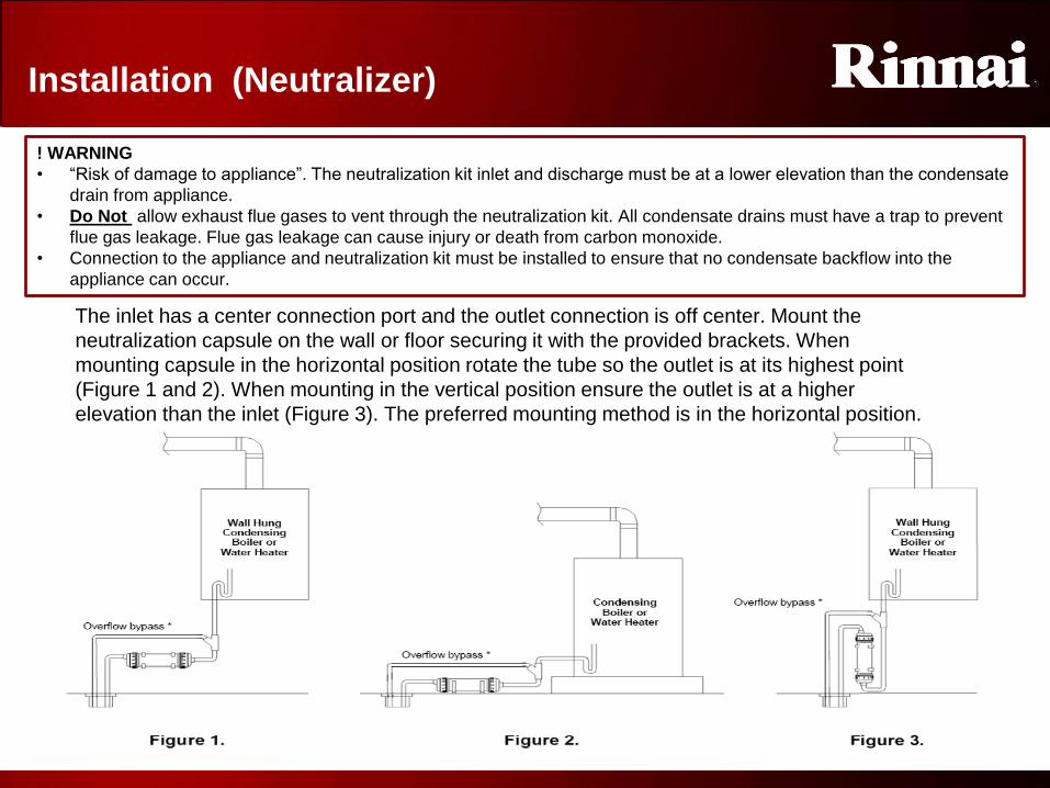
8
8
88
! WARNING
• “Risk of damage to appliance”. The neutralization kit inlet and discharge must be at a lower elevation than the condensate
drain from appliance.
• Do Not allow exhaust flue gases to vent through the neutralization kit. All condensate drains must have a trap to prevent
flue gas leakage. Flue gas leakage can cause injury or death from carbon monoxide.
• Connection to the appliance and neutralization kit must be installed to ensure that no condensate backflow into the
appliance can occur.
Installation (Neutralizer)
The inlet has a center connection port and the outlet connection is off center. Mount the
neutralization capsule on the wall or floor securing it with the provided brackets. When
mounting capsule in the horizontal position rotate the tube so the outlet is at its highest point
(Figure 1 and 2). When mounting in the vertical position ensure the outlet is at a higher
elevation than the inlet (Figure 3). The preferred mounting method is in the horizontal position.
Neutralizer Installation

8
9
89
Installation (Neutralizer)
• Connections to the appliance and neutralization kit must be installed to ensure that no condensate
backflow can occur.
• Connect corrosion resistant piping and secure it to the floor or wall to prevent movement. Do not route the
condensate line through any area that is exposed to freezing temperatures. If traffic poses a risk, install
some protection to prevent movement and/or damage
• Ensure the condensate will flow freely from the appliance drain into the capsule then to the drain.
• The end of the condensate drain pipe should be open to the atmosphere, not under water or other
substances.
• Access to the discharge is necessary for proper maintenance in order to check the effectiveness of the
neutralizing media, using pH test strips.
NOTE: IF there is no gravity drain available, Install a condensate removal pump designed for use on
condensing boilers and furnaces. The condensate pump must be equipped with an over flow switch
to prevent the appliance from running should a failure occur.
Check with your local water authority for regulations regarding discharge of
treated condensate to the drain or sewer system.
Neutralizer Installation

9
0
90
Scale Control System
Rinnai’s Scale Control System is a unique product providing excellent lime scale
prevention and corrosion control for tankless water haters. The scale control
conditions the water resulting in consistent scale control prevention and corrosion
control for predictable periods of time. The system works in the following ways:
• Keep scale causing minerals in solution, inhibiting lime scale formation.
• Changes the shape of the precipitated lime scale preventing accumulation.
• Coats wetted surfaces with a micro-thin layer that acts as a corrosion buffer.
• Helps soften and remove existing lime scale over time.
Part Numbers:
Scale Control

9
1
91
Installation (Scale Control)
Scale Control Installation

9
2
92
Installation (Scale Control)
Scale Control Installation

9
3
93
Recess / Pipe Cover Compatibility Parts List
PIPE COVER / RECESS BOX COMPATIBILITY
Model Pipe Cover Boxes Recess Boxes
V53e PC-20-W RGB-20U
V65e and V75e PCD03-EWV RGB-25U-C
R75LSe / RL75e
PCD03-SM2
RGB-25U or
RGB-25U-MSAL
MSAL=Moisture Seal Aluminum
R94LSe / RL94e
R98LSe or R98LSe ASME PC-32-S RGB-32-W
RC80e PCD07-SM
Bottom plate sold separately-PCD07-SM-BP RGB-CWTH
RC98e
RL75e and RL94e (VA,VB,VC) PCD03-SM2 RGB-25U-C
RU80e or RU98e (KB series) PCD07-SM RGB-CTWH-2
V65i and V75i PCD03-EWV
Not Applicable
R75LSi / RL75i PCD03-SM2 (use PCD03-SM for 2009 models or earlier) R94LSi / RL94i
R98LSi or R98LSi ASME PC-32-S
RC80i / RU80i PCD07-SM
Bottom plate sold separately-PCD07-SM-BP RC98i / RU98i
The below chart shows applicable part numbers for each model:
Pipe Cover

9
4
94
Accessories
PIPE COVER BOXES
• Pipe Cover boxes mount underneath indoor or outdoor units to cover visible pipes and valves, increasing security and allowing for possible insulation of pipes.
• Pipe cover boxes connect to the bottom of indoor or outdoor water heaters, providing an aesthetically pleasing cover for incoming piping and electrical connections
• Pipe cover boxes also provide additional security and allow insulation of incoming plumbing inside the box
• Ensure the correct model box is ordered for each model water heater (color and design should be considered)
Pipe Cover
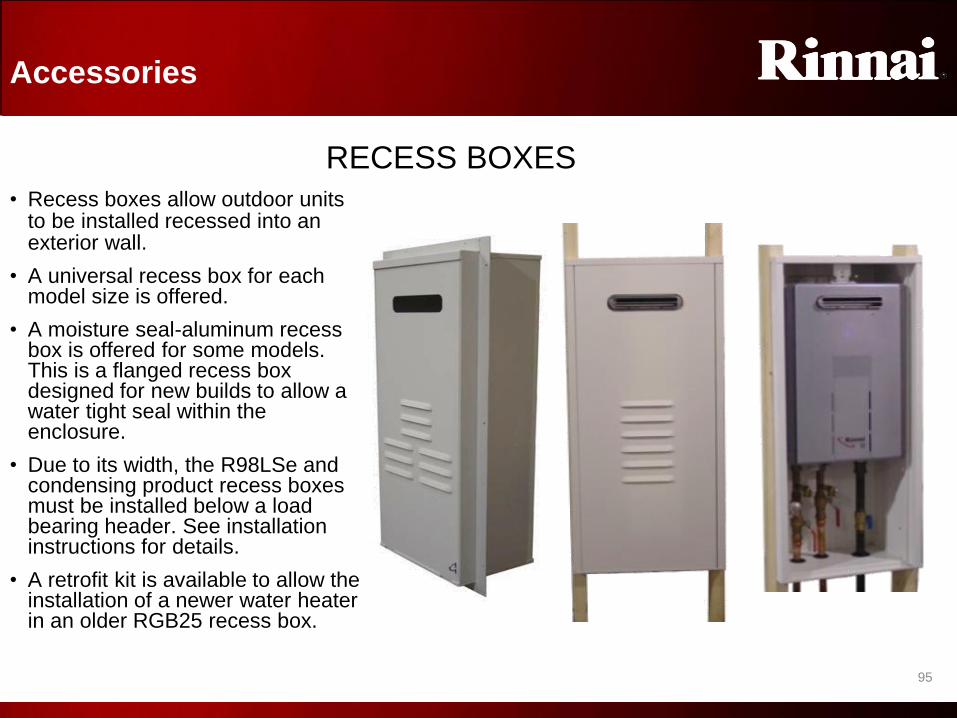
9
5
95
Accessories
RECESS BOXES
• Recess boxes allow outdoor units to be installed recessed into an exterior wall.
• A universal recess box for each model size is offered.
• A moisture seal-aluminum recess box is offered for some models. This is a flanged recess box designed for new builds to allow a water tight seal within the enclosure.
• Due to its width, the R98LSe and condensing product recess boxes must be installed below a load bearing header. See installation instructions for details.
• A retrofit kit is available to allow the installation of a newer water heater in an older RGB25 recess box.
Recess Box

9
6
96
Why is a
multi-unit
control
technology
needed?
Rinnai’s new MSB technology
If the above system of VB product did not use a multi-control system, it could take in excess of 2.0 gpm to fire any single unit
(5 units multiplied by a 0.4 gpm activation rate).
Example: If 1.5 gpm were flowing, this would divide evenly through all five units (remember, with no control system, ALL flow
control valves are open). 1.5 gpm ÷ 5 units = 0.3 gpm (less than each unit’s activation rate).
• Couldn’t pressure activation or regulator valves overcome this issue—turning on consecutive units based on incoming
pressure changes? Yes, but…
• The cost of such valves—including the labor to install them—could be prohibitive to many applications;
• And, such a system would always fire the water heaters in the same order—meaning that, over time, unit #1 would have
more usage than unit #5
• Furthermore, if one product experiences a diagnostic code, cold water would pass through it—diluting the overall
temperature at the output(s). This would occur until the disabled unit was reset.
• The solution: Rinnai’s MSB and EZConnect® technology….
MSB Technology

9
7
97
Rinnai’s improved upon its previous MSA
technology with the release of the MSB
platform.
Each MSB-M board will connect up to 5
water heaters. However, now up to 5
MSB-M boards can be connected
together with communication cables—now
as many as 25 water heaters will operate
as a single system!
Furthermore, dip switches will allow the
installer to select how many units are in
standby with their water control valves
open (ready to fire)—thus allowing quicker
response time when demand increases.
Depending on which model water heater
is used, an MSB system could have an
operating range of 10,000 to as great as
5.9 million Btu and anywhere in between.
Or, in terms of flow rate: 0.4 gpm to 245
gpm and anywhere in between!
Rinnai’s new MSB technology
MSB-M
control
board
MSB-M
control
board
MSB-M
control
board
MSB-M
control
board
MSB-M
control
board
MSB-C1 cable
Connects water
heaters within a
5-bank MSB
system
together
MSB-C2 cable
Connects MSB-
M boards
together
MSB Technology

9
8
98
MSB Compatibility Parts List
Part selection is important! Refer to the table below to ensure that the correct parts are selected for each
system.
NOTE: V-series products will accept MSB parts—see the note below. This would likely only be
performed for retrofit applications.
NO. OF UNITS 2* 3 4 5 6 7 8 9 10 11 12 13 14 15 16 17 18 19 20 21 22 23 24 25
Part Needed The following components are compatible for all VA, VB, and KA (HP) products. For V series, see note at MSB-C3
EZConnect ®
cable
1
MSB-M 1 2 3 4 5
MSB-C1 1 2 3 2 3 4 5 6 5 6 7 8 9 8 9 10 11 12 11 12 13 14 15
MSB-C2 1 2 3 4
MSB-C3
V-series products will accept the MSB technology. However, substitute the MSB-C3 cable for any
MSB-C1 cable and Connector A cable
V-Series products will not accept EZConnect either (except R98/C98 V-Series)
*EZConnect is the preferred (and least expensive) method for operating two units together; however, an MSB system is
capable of operating only two units
NOTE: This is an overview only. Please refer to the MSB/EZConnect installation instructions OR the expanded
edition of MSB training for more detail.
MSB Compatibility

9
9
99
NOTE: With any EZConnect configuration,
• The temperature controller connected to the primary or #1 unit will control temperature on both units in the system. The
temperature controller on the other unit in the system will only display (not change) the temperature. They will also display
individual diagnostic codes.
• All units manufactured after July, 2008 : When installed in an MSA / MSB or EZConnect setup and needing temperatures
higher than 140° F only one MCC-91 controller is required—Installed on the primary unit. All other units will follow the
primary unit’s temperature without the purchase of the MCC-91 controller.
Dip Sw 5 ON 1 unit in standby (allow for quicker activation for flow rates within the capacity of a single unit)
Dip Sw 5 OFF
(default)
2 units in standby (allows for quicker delivery temperature for flow rates requiring both units)
New for 94/75 Series VB units: Dip Switch 5 in the bank of 6 will control whether one or both units are
ready to fire when in standby:
EZConnect
standby setting
NOTE: This Dip Switch will not affect systems operating with an MSA / MSB board
EZConnect® – Connecting two units
When connecting only two LS/HP Series
model water heaters, an MSA or MSB
board is not necessary. An EZConnect
cable can be used connecting to a
special harness on the primary unit and
the PCB on the secondary unit (see
pictures). Three or more of these
models will require the MSA / MSB
components.
EZConnect Connection
EZConnect
Connection
EZ Connect

1
0
0
100
APPENDIX A
INSTALLATION EXAMPLES
Installation Examples

1
0
1
101
2008 HGTV Green Home
Example

1
0
2
102
Show Village Home
Example
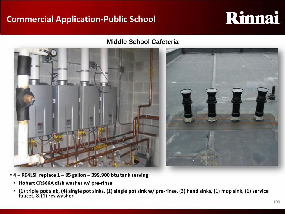
1
0
3
103
Commercial Application-Public School
• 4 – R94LSi replace 1 – 85 gallon – 399,900 btu tank serving:
• Hobart CRS66A dish washer w/ pre-rinse
• (1) triple pot sink, (4) single pot sinks, (1) single pot sink w/ pre-rinse, (3) hand sinks, (1) mop sink, (1) service faucet, & (1) res washer
Middle School Cafeteria
Example
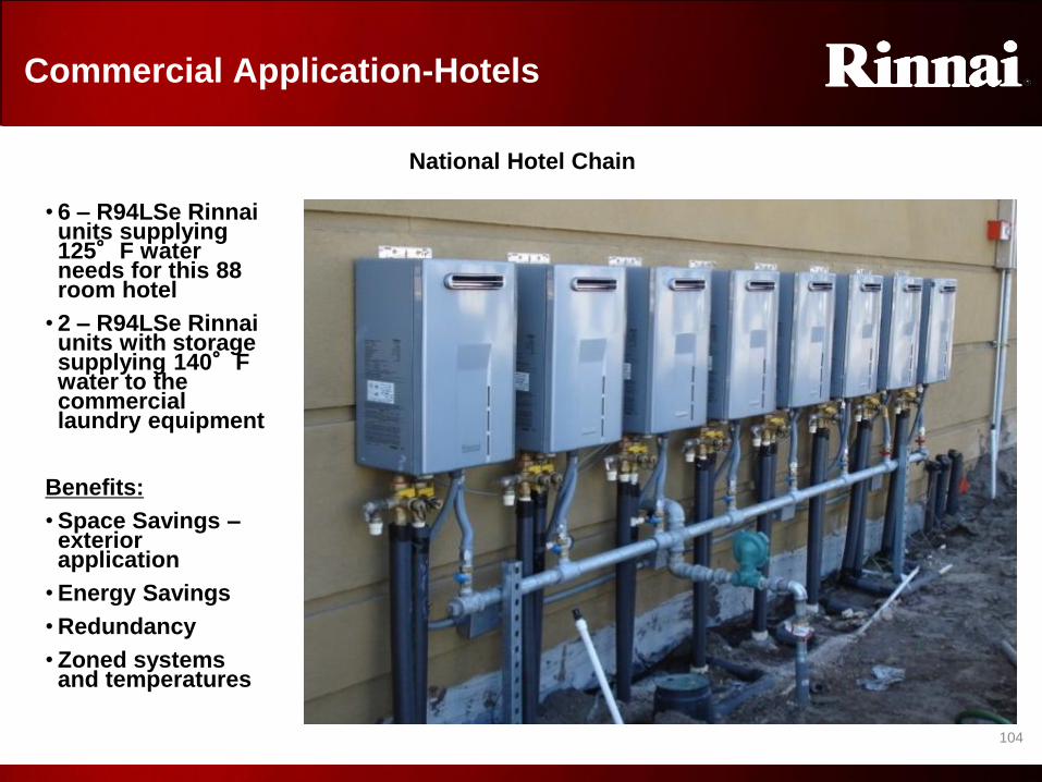
1
0
4
104
Commercial Application-Hotels
• 6 – R94LSe Rinnai units supplying 125°F water needs for this 88 room hotel
• 2 – R94LSe Rinnai units with storage supplying 140°F water to the commercial laundry equipment
Benefits:
• Space Savings – exterior application
• Energy Savings
• Redundancy
• Zoned systems and temperatures
National Hotel Chain
Example

1
0
5
105
Commercial Application-Hotels
22 – R94LSi
Rinnai units
105 room hotel
and
convention
center with
commercial
laundry and
full service
kitchen
National Hotel Chain
Example

1
0
6
106
Commercial Application-Restaurant
90 Gallon 500,000 btu tank water heater replaced with 5 – R94LSi Rinnai
units horizontally vented using snorkel kits.
National Full Service Restaurant
Example
1
0
7
107
APPENDIX B
MSB Multi-Unit Controller
MSB Multi Unit

1
0
8
108
Rinnai’s Multi-unit controller technology
An EZConnect® cable or MSA/MSB controller ensures each unit is firing at the same rate during operation
and electronically balances the flow rate through each unit.
In addition, this technology sequences or rotates between units to prevent one unit from being overworked.
History of Rinnai’s Multi-unit Controllers
VA, VB, VC, KA and KB
Products*
1-EZConnect cable or MSA-2M technology and moving forward MSB technology
V Series products MSA-2M technology and moving forward MSB technology (some components will vary)
2424/2402 Original MSA-M Technology
*NOTE
Some smaller models (RV53, R63, etc) may not accept MSA /MSB components. These units
are seldom operated in tandem—if so, PVA valves can be used. Contact Rinnai if needed for
more information.
The following features have not changed from MSA to MSB technology:
• With any MSA/MSB or EZConnect configuration, the temperature controller connected to the primary
or #1 unit will control temperature on ALL units in the system. • Temp controllers on other units in the system will only display (not change) the temperature. They will also display
individual diagnostic codes—therefore it is recommended to ensure temperature controllers are connected to all
units.
• Additionally, if multiple MSB systems are used together (6 or more units), the controller in the first unit of the Master
MSB will control the entire system.
• Water heaters that do not have a temperature controller will operate at the temp setting of this first unit.
• All units manufactured after July, 2008 installed in an MSA / MSB or EZConnect setup and needing
temperatures higher than 140° F will only require an MCC-91 controller installed on the primary unit. • All other units will follow the primary unit’s temperature without the purchase of the MCC-91 controller.
• For proper operation, it is not recommended that different models be connected together. Combining
different models may result in lower performance.
MSB Multi Unit
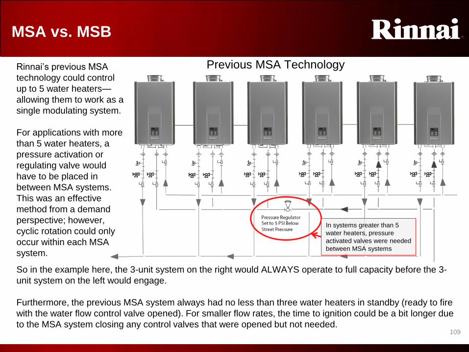
1
0
9
109
MSA vs. MSB
Rinnai’s previous MSA
technology could control
up to 5 water heaters—
allowing them to work as a
single modulating system.
For applications with more
than 5 water heaters, a
pressure activation or
regulating valve would
have to be placed in
between MSA systems.
This was an effective
method from a demand
perspective; however,
cyclic rotation could only
occur within each MSA
system.
So in the example here, the 3-unit system on the right would ALWAYS operate to full capacity before the 3-
unit system on the left would engage.
Furthermore, the previous MSA system always had no less than three water heaters in standby (ready to fire
with the water flow control valve opened). For smaller flow rates, the time to ignition could be a bit longer due
to the MSA system closing any control valves that were opened but not needed.
Previous MSA Technology
In systems greater than 5
water heaters, pressure
activated valves were needed
between MSA systems
MSA vs MSB
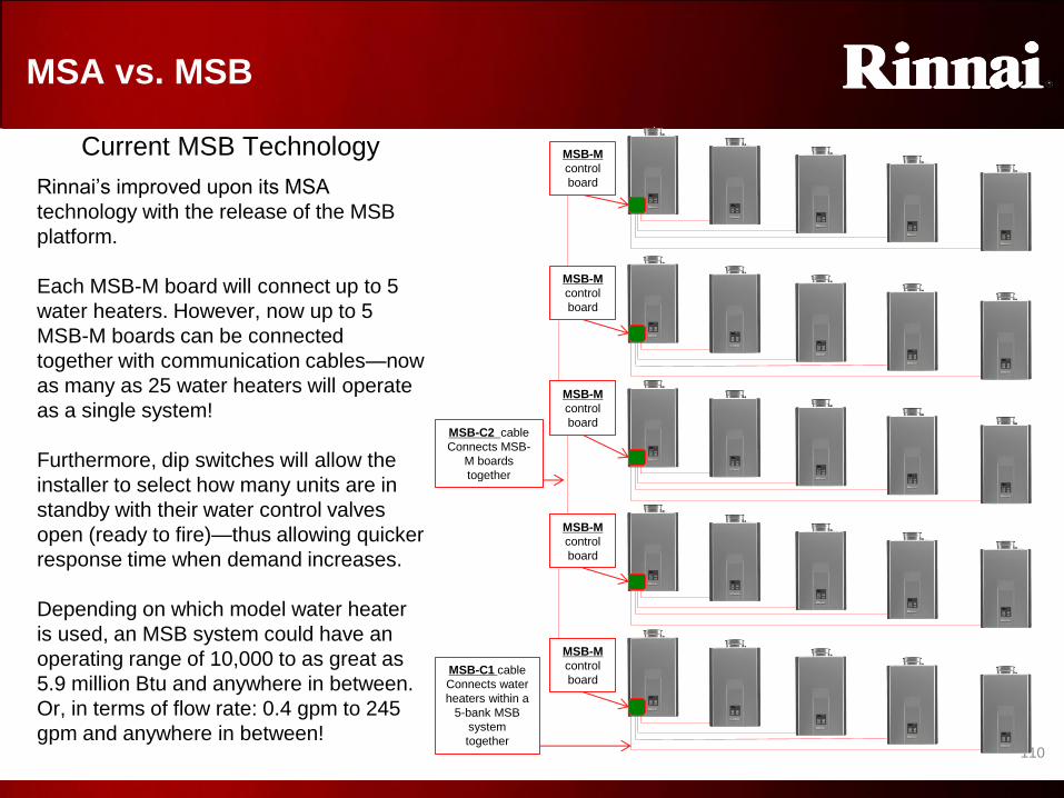
1
1
0
110
Rinnai’s improved upon its MSA
technology with the release of the MSB
platform.
Each MSB-M board will connect up to 5
water heaters. However, now up to 5
MSB-M boards can be connected
together with communication cables—now
as many as 25 water heaters will operate
as a single system!
Furthermore, dip switches will allow the
installer to select how many units are in
standby with their water control valves
open (ready to fire)—thus allowing quicker
response time when demand increases.
Depending on which model water heater
is used, an MSB system could have an
operating range of 10,000 to as great as
5.9 million Btu and anywhere in between.
Or, in terms of flow rate: 0.4 gpm to 245
gpm and anywhere in between!
MSA vs. MSB
MSB-M
control
board
MSB-M
control
board
MSB-M
control
board
MSB-M
control
board
MSB-M
control
board
MSB-C1 cable
Connects water
heaters within a
5-bank MSB
system
together
MSB-C2 cable
Connects MSB-
M boards
together
Current MSB Technology
MSA vs MSB
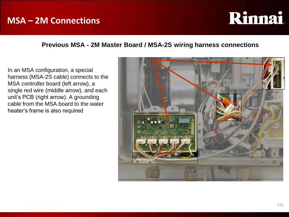
1
1
1
111
In an MSA configuration, a special
harness (MSA-2S cable) connects to the
MSA controller board (left arrow), a
single red wire (middle arrow), and each
unit’s PCB (right arrow). A grounding
cable from the MSA board to the water
heater’s frame is also required
MSA – 2M Connections
Previous MSA - 2M Master Board / MSA-2S wiring harness connections
MSA – 2M Connections

1
1
2
112
MSB – M: Connections within a 5-unit subsystem
MSB-M Master Board / MSB-C1 or C3 wiring harness connections
1. In an MSB configuration, a short cable is provided (connector A).
This connects from the MSB-M board’s far left port to the water
heater’s PCB in which the MSB is installed (as shown). NOTE: The
single red wire previously used for MSA systems is no longer needed
(nor supplied)
2. A grounding wire from the MSB board to the water heater’s frame is
also required (as shown)
3. For VA (LS), VB (LS), and KA (HP) models the connection to water
heaters 2 through 5 use cable MSB-C1
• This cable also does not use the single red wire
• This cable now has a grounding wire that is to be connected at
both ends (to both water heaters)—as shown
4. If an MSB-M is used with a V-series model, the single red wire
connection is still required. Therefore a separate cable is available—
MSB-C3
MSB-C1
Connector
B-must be
grounded at
both ends
1 1 Connector A
2 3
3
MSB – 5 units

1
1
3
113
• For applications with more than 5-Rinnai water heaters, an MSB-C2 cable can connect MSB-M boards together—allowing
the entire system to work as one.
• Two yellow terminal cables are provided with each MSB-C2 kit. These are to be installed on the first and last MSB-M boards
in the series
• The first MSB-M board in the system should have the yellow terminal cable seated in the top left port
• The last MSB-M board in the system should have the yellow terminal cable seated in the top right port
• See the following examples:
• For 6 though 10 units using 2-MSB-M boards, ensure the yellow terminal cable is installed as follows
MSB-C2
MSB-M Master Board / MSB-C2 wiring harness connections
Yellow terminal
to be installed in
the top left port
on the first MSB-
M board
NOTE: THIS IS
THE MASTER
MSB
MSB – M: Connections between a subsystem
• For systems using 3, 4 or 5-MSB-M boards, ensure the yellow terminal cable is installed as follows
Yellow terminal
to be installed in
the top right port
on the last MSB-
M board
MSB-C2
Yellow terminal
to be installed in
the top left port
on the first MSB-
M board
Yellow terminal
to be installed in
the top right port
on the last MSB-
M board
MSB-C2
MSB Between Subsystems

1
1
4
114
• No DIP switch settings are needed on the
water heaters’ PCB’s.
• However, each MSB has DIP switches that
should be set for the following reasons • Addressing each MSB within a system—when
set correctly the LED light on each MSB should
illuminate (shown here)
• To assign how many units should be “ready-to-
fire” upon initial water flow—this will be
dependent on the application’s needs (next
slide)
MSB-M Master Board / MSB-C2 wiring harness connections
MSB – M: DIP Switch Settings
#1. DIP 3=ON THIS IS THE MASTER MSB –
closest to cold water supply
#2. DIP 4=ON
#3. DIP 3 & 4=ON
#4. DIP 5=ON
#5. DIP 3 & 5=ON
When addressed
correctly, this
LED should
illuminate
MSB Dip Switches

1
1
5
115
• As the default setting, 3 units will open their servo valves until flow demand is determined. This can be
altered between 1 and 3 units dependent on the application’s needs
• The more units in standby, the quicker delivery temperature for higher flow rates
• The fewer units in standby, the quicker activation for lower flow rates
• If fewer than 3 units in standby is desired, refer to the Dip SW setting chart below
• When installation is completed, do a test run for all units.
• The temperature setting for all water heaters in the system is controlled by the temperature controller
connected to the water heater with the Master MSB Board. Temperature controllers connected to the other
units will provide maintenance codes for their respective units.
MSB – M: DIP Switch Settings
DIP 1 & 2 OFF
3-units in standby (default)
DIP 1 ONLY ON
2-units in standby
DIP 1 & 2 ON
1-unit in standby
When multiple water heaters are operating, they will attempt to supply equal
amounts of hot water. • By default, three water heaters will be in standby (or a “ready-to-fire” state)—meaning that the
water flow control valves of three units are open. Those units will fire immediately on initial
water flow demand.
• Once the MSB system determines water flow demand, only the necessary number of water
heaters will fire to meet that demand. Water heaters not firing will close their valves.
• Each MSB-C1 cable has an LED indicator to report the status of each water heater:
LED State Unit status with no flow established by MSA/MSB Unit status after MSA/MSB establishes flow LED On Solid Water flow control valve is open. Unit is in standby and will be among the
first to fire. Unit is fired and running.
LED Flashing Slow Water flow control valve is closed/ unit is not in standby.
LED Flashing Fast Error detected at this unit (Error will not reset until power at MSA/MSB or this unit is recycled). LED Off No unit detected at this plug
LED Status indicator
MSB Dip Switches

1
1
6
116
So based on the previous recommendation,
operation would work as follows:
• When water flow starts, the first three units of
the Master MSB #1 will pass water through
them. ALL other water heaters in the system
will have their flow control valves closed—not
allowing water flow initially
• If water flow is less than 1.2 gpm (3 units X
0.4 gpm activation), 1 or 2 of the active units
will close their valves (depending on total
flow rate)
• Otherwise, the MSB system will determine
demand and quickly commission as many
units as needed
• Once subsystem #1 is at about 90% of its
capacity, subsystem #2 will begin to
commission its units. The number of units
commissioned will be based on the
increase in demand.
• This sequence will continue in the same
manner
• NOTE: If an application requires a large
amount of flow very quickly at startup, the
MSB-C2 cable between subsystems 1 & 2 can
be omitted.
• This will allow 6 units to be in standby (3
each from the first two subsystems)
• This will also require a 0.8 gpm minimum
activation
MSB: Basic Operation
MSB-M #1
control board
(Master)
MSB-M #2
control board
MSB-M #3
control board
MSB-M #4
control board
MSB-M
#5
control
board
MSB-C1 cable
Connects water
heaters within a
5-bank MSB
system
together
MSB-C2 cable
Connects MSB-
M boards
together
For large
flow
applications,
this MSB-C2
cable
can be
omitted
MSB Basic Operation

1
1
7
117
The order in which each water heater operates is
occasionally rotated to ensure equal usage among
the entire system.
• When power is first applied, the Master MSB is
designated as the “parent subsystem.” All other
MSB subsystems are designated as “branches.”
• Every 24 hours the parent subsystem will rotate to
the next branch.
• So MSB #2 would become the parent after the
first 24 hours
• NOTE: this is 24 hours of applied power—not
operation time
• IMPORTANT: If the master MSB is set for 3-
units in standby (via its DIP settings), this will
transfer to each subsystem when it becomes
the parent. So, in this example, MSB #2 would
then have three units in standby.
• If a subsystem is not operating at full capacity—
meaning one or more units are not needed—a
rotation sequence will also occur WITHIN that
subsystem moving in a counterclockwise fashion
• NOTE: this works in the same fashion as the
previous MSA system. If needed, refer to TB-54
for additional information
MSB: Rotation
MSB-M #1
control board
(Master)
MSB-M #2
control board
MSB-M #3
control board
MSB-M #4
control board
MSB-M #5
control board
MSB Rotation
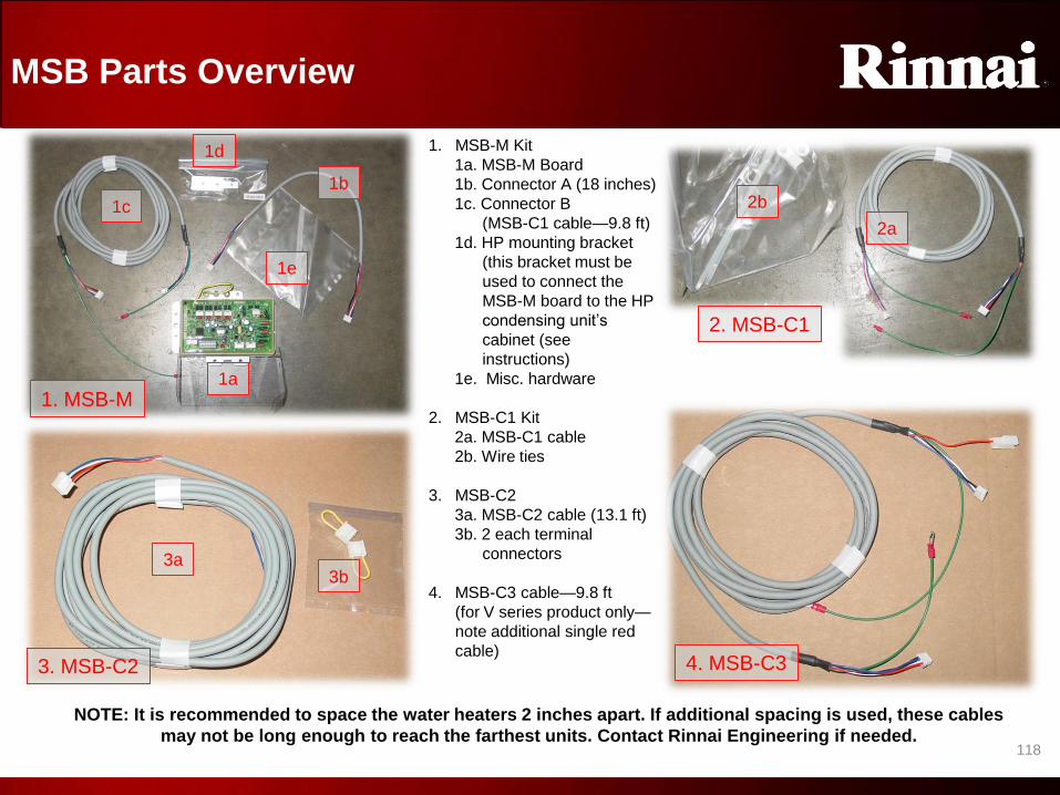
1
1
8
118
1. MSB-M Kit
1a. MSB-M Board
1b. Connector A (18 inches)
1c. Connector B
(MSB-C1 cable—9.8 ft)
1d. HP mounting bracket
(this bracket must be
used to connect the
MSB-M board to the HP
condensing unit’s
cabinet (see
instructions)
1e. Misc. hardware
2. MSB-C1 Kit
2a. MSB-C1 cable
2b. Wire ties
3. MSB-C2
3a. MSB-C2 cable (13.1 ft)
3b. 2 each terminal
connectors
4. MSB-C3 cable—9.8 ft
(for V series product only—
note additional single red
cable)
MSB Parts Overview
1. MSB-M
2. MSB-C1
3. MSB-C2 4. MSB-C3
1a
1b
1c
1d
1e
2a
2b
3a 3b
NOTE: It is recommended to space the water heaters 2 inches apart. If additional spacing is used, these cables
may not be long enough to reach the farthest units. Contact Rinnai Engineering if needed.
MSB Parts Overview

1
1
9
This concludes Rinnai’s
Tankless Water Heater Training Program
Product Knowledge / Installation
Fundamentals
Level I/II
Advance the next slide to test your
knowledge.
Conclusion

PROPERTIES
On passing, 'Finish' button: Goes to Next Slide
On failing, 'Finish' button: Goes to Next Slide
Allow user to leave quiz: After user has completed quiz
User may view slides after quiz: At any time
User may attempt quiz: Unlimited times120