Embed Size (px)
Citation preview

Comfort onboard yachts in anchored conditions
G. Gaillarde, R.P. Dallinga, G. Loeff, H. Luisman, MARIN1
1. Introduction By limiting comfort and on-board activities poor seakeeping affects the sheer enjoyment of a yacht at anchor. Over the years the focus has been mainly on the roll motion, perceived as an important cause of the trouble and an issue that can be influenced in the design, most yachts are built nowadays with active roll stabilisation. In the present work we will review contribution of roll and the effect of various means to stabilize it in comfort issues. The present paper builds on lessons learned in the course of a long history of seakeeping investigations (see Figure 1), involving concept numerical work, model tests and onboard measurements. It discusses the basics of motor yacht seakeeping, the techniques of various motion control devices and the way to quantify the performance of the
proposed solutions. New potential solutions are also briefly presented. Throughout the paper examples of motions, accelerations and quantification of the comfort are provided for a 175 tonnes hard chine yacht at anchor. Discomfort is hereafter represented through the Motion Illness Rating value, which is derived from wave induced accelerations. Discomfort due to vibrations or high order motions in general (induced by slamming for example) were discarded in the present study.
2. Yacht seakeeping at anchor The chosen base case is a 175 tonnes hard chine yacht. The 3.0m transverse stability of the original leads to a natural roll period in water of about 3.9 seconds. This short period is typical for light displacement high speed yachts. In the present study the metacentric height was varied to assess the effect of the roll period on comfort. The results of calculations presented hereafter are obtained by means a conventional strip theory code. The empirical roll damping coefficient was tuned with model test results. Non-linear character of the damping was not taken into account in the present study. In frequency domain calculations the motions and derived quantities like local accelerations and relative motions are described in terms of response functions (RAO’s), the amplitude per unit wave amplitude. These are a function of wave frequency and wave direction. Convolution with a wave spectrum yields the response in irregular waves, which is usually described in terms of the standard deviation (rms) value.
1 Maritime Research Institute Netherlands, Wageningen, The Netherlands, [email protected]
Figure 1: Overview of tested motor yachts
0
20
40
60
80
100
120
140
1970 1980 1990 2000 2010
Year of tests [-]
Lpp
[m]

A first step in the calculation process is the calculations of the roll excitation, which is shown in Figure 2 here below. For the present design the highest roll excitation is concentrated around beam seas.
Figure 3 shows the resulting response functions of the heave, roll and pitch motion as a function of wave direction and wave frequency. These contour plots provides a quick overview of the heading and wave frequencies that will induce the largest responses. The largest heave response is obtained in relatively long waves compared to the hull dimensions, the largest roll response in beam waves having the same period than the natural period of roll of the yacht, and the largest pitch response in waves from quarter to head or following directions with wave length slightly longer than the hull length.
Figure 2: RAO roll excitation as a function of wave direction and frequency for 3m GM
Figure 3: RAO’s of motions as a function of wave direction and frequency, for 3m GM

For the same displacement, the calculations were repeated for a lower GM (1.25m), yielding a longer natural roll period of 5.5 seconds. The following figure illustrates the effect GM variation of roll moment excitation, note the difference in the scale.
The same data is shown hereafter in 2D plots in waves from abeam and from the bow quarter. The figures on the left show the roll response, while the figures on the right show the roll excitation. The larger excitation obtained for the higher GM condition is clearly illustrated in beam seas, which also results in a higher roll response. Noteworthy is the fact that in waves from the bow quarter, despite the fact that the excitation is lower, the highest roll response of the 1.25m GM is larger than for the 3.0m GM. This result can be explained by the decreasing wave making roll damping component with increasing roll period.
The combined heave, roll and pitch motions result into vertical and transverse accelerations. Because most of the stabilising system are focusing on roll (for the obvious reason that it is the largest motions but also the easiest to damp with relatively low input), the following section will focus on these systems. Various techniques will be discussed.
Figure 4: Response of roll excitation for 3m and 1.25m GM
Figure 5: Response of roll and roll excitation for 3m and 1.25m GM in beam seas
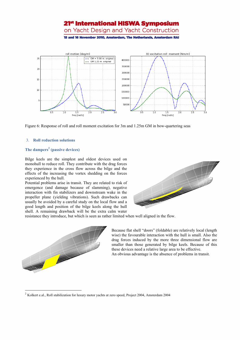
3. Roll reduction solutions The dampers2 (passive devices) Bilge keels are the simplest and oldest devices used on monohull to reduce roll. They contribute with the drag forces they experience in the cross flow across the bilge and the effects of the increasing the vortex shedding on the forces experienced by the hull. Potential problems arise in transit. They are related to risk of emergence (and damage because of slamming), negative interaction with fin stabilizers and downstream wake in the propeller plane (yielding vibrations). Such drawbacks can usually be avoided by a careful study on the local flow and a good length and position of the bilge keels along the hull shell. A remaining drawback will be the extra calm water resistance they introduce, but which is seen as rather limited when well aligned in the flow.
Because flat shell “doors” (foldable) are relatively local (length wise) the favourable interaction with the hull is small. Also the drag forces induced by the more three dimensional flow are smaller than those generated by bilge keels. Because of this these devices need a relative large area to be effective. An obvious advantage is the absence of problems in transit.
2 Kolkert e.al., Roll stabilization for luxury motor yachts at zero speed, Project 2004, Amsterdam 2004
Figure 6: Response of roll and roll moment excitation for 3m and 1.25m GM in bow-quartering seas

“Flopper stoppers” are devices suspended at a transverse beam outside the hull. They need to be lowered relatively deep to reduce the inevitable wave roll induced excitation. Their contribution, like the shell doors is highly dependent on their size. Practical issues are the deployment and storage as well as aesthetical aspects. A drawback of suspension from the keel plane is the reduced lever arm, which requires an increase the area. Foldable ‘umbrella’ type of constructions could be considered. However they should be able to cope with the large added mass and drag forces.
Even if never used yet on motor yachts but known for ages in practice on sailing yachts, sails are also a possible way introduce additional damping. Because the air density is much lower than water density, their contribution to the damping (at equivalent size than underwater systems) large areas are required to be effective. Using such device for propulsion assistance in transit condition may allow the introduction of such system into the yacht market. Many studies3 4 learned that a lightly dampened passive U-type anti-roll tank are very effective in the reduction of roll motions. This characteristic, combined with the possibility to disable the tank quickly by closing the air ducts and the expected low noise production and zero power requirements, makes it an attractive (and “green”) solution for motor yachts.
Because the tank relies on a resonant response of the tank contents to the motions of the ship, a careful tuning of the natural period of the ship and the tank as well as the internal damping of the tank are important design issues. For a given wing-tank area (which determines the restoring term in the natural period) the height of the connecting duct is the remaining design parameter for the tuning. The “added” mass associated with the high acceleration of the fluid through the narrow duct is an important factor.
The internal damping is governed by the vortex shedding at the point where the duct merges in the wing-tanks, the drag of structural elements in the tank and the frictional drag. The first two components are considered as major factors. By nature these elements are non-linear in character (the drag force is more or less proportional to the square of the flow velocity). Because this induces a relatively high tank response at relatively low roll amplitudes this is an interesting characteristic to obtain a high degree of stabilisation in low wave heights. At the same time the relatively low response in extreme conditions prevents impacts at the tank top
3 Stigter; ‘The Performance of U-tanks as a Passive Anti-Roll Device’, TNO Report No. 81S, Feb. 1966. 4 Dallinga R.P., Roll Stabilisation at Anchor: Hydrodynamic Aspects of the Comparison of Anti-Roll Tanks and Fins, PROJECT 2002, Amsterdam.

Drawback of a U-type tank are the space requirements and the effort of carefully tuning the tank with the roll period and roll damping of the yacht. However, when introduced in the design from the first concept stage, an anti-roll tank can be seen as a powerful and efficient passive device. The energy users (active devices) Active stabiliser fins are the most the most commonly applied roll stabilisation device introduced in the yacht market of the last 15 years.
The idea of “kicking” the fins to stabilize roll was investigated for the first time at MARIN, in 1998, and reported by Dallinga5 in 1999. The roll damping is governed by the energy dissipated by the inertia and drag forces (the integral of the product of the roll velocity and the opposing damping forces). In this process the roll velocity may not be treated as a constant factor, in particular at the lowest fin velocity where the fin transition may take as much as one-third of the natural period of roll. Because the forces are independent of the roll velocity this way of stabilisation is limited to modest wave heights.
The initial inertia force during the initial acceleration and the drag forces in the transition phase contribute to the damping. The combined effect of the forces and their timing with respect to the roll velocity determine the result. A potential drawback of kicking fins is that the “kick” can sometimes be felt onboard as jerk (the rate of change of the acceleration). A solution is to adopt a larger fin that will provide the same reaction force with avoiding a too large kick in the starting phase. An obvious drawback then is the size of the device which is becoming relatively important. Magnus effect can also be used to generate damping. Such system makes uses of the lift acting on a spinning cylinder swinging in fore and aft direction. Careful timing of the swinging motion with the roll motion yields the required damping. Gyroscopes, spinning around a vertical axis and suspended in such a way that they can pitch freely, function very much like an anti roll tank. Tuning of the natural period of pitch of the suspended gyroscope with the natural period
of roll makes them function as follows: • a roll velocity of the ship causes a pitch moment acting on the spinning gyroscope; • because the gyroscope pitches in resonance, the pitch out of out of phase with the roll velocity • because of this the gyroscope pitch velocity induces a roll moment on the ship that counteracts the roll velocity.
5 R.P. Dallinga, ” Roll stabilisation of motor yachts: use of fin stabilizers in anchored conditions”, Projects 99, Amsterdam, November 1999.

An advantage of gyroscopes is perhaps that relatively large damping can be obtained in combination with relatively short natural roll periods. An issue in the design is the internal damping of the gyroscope pitch motion.
A cycloidal propulsor is a thrusting device with an axis of rotation that is approximately perpendicular to the direction of travel. A number of lifting blades equally spaced at a fixed orbit diameter, rotate about this axis. Each blade is further controlled in its orbit such that a component of force in a desired direction is obtained. By allowing quickly alternating transverse force and being located under the keel (so well below the centre of gravity), such devices can be used to generate roll damping with the same principle than all the other active systems.
Quite similar on the principle than an anti-roll tank, moving-mass system is also a solution applied on few ships. The mass, actively moved transversally on the ship, can work at anchor but also in transit conditions. The efficiency of the system lays in the mass, its location and the control algorithm. Such system also exists on large navy vessel to compensate for heel (so, quasi-static aspect, like ballast tanks). Moving at natural roll frequency of the vessel requires different types of characteristics and much faster motors. The energy converters (to be developed)
Resonant motions are stabilized by increasing the dissipated energy. An interesting concept to make this energy available on board. In the case of roll stabilisation by means of passive resonant systems the challenge is to retrieve the energy dissipated by the “internal” damping. For a U-type anti roll tank this might be achieved by using a very smooth tank with a impeller in the cross duct driving a generator. For the gyroscope this could be achieved with a connection between the transverse (pitching) axis with a generator. Although the roll excitation is large enough to be the cause of significant discomfort (also because of the
low roll damping) its absolute magnitude is limited. This limits the energy that can be extracted in this way.

Much more promising from an energy generation point of view is the stabilisation of pitch by connecting the bow to
the sea floor. The adjacent figure indicates the effect of a single vertical line with a particular amount of damping on the distribution of the vertical accelerations over the length of a 65m displacement yacht in a regular head wave. The response function drops nearly 50%, yielding a considerable increase in comfort in the fore and aft ship. At a (common) wave period of 7s the system generates about 25kW per m significant wave height squared. The same may investigated for roll, adding however the extra challenge to keep weathervaning possible. A practical issue is obviously the mooring through a vertical line with a high pre-tension. A large ballast weight, fixed suction anchors or by using large ‘foldable’ flopper stoppers may be an option. Harbours or famous yacht spots could pre-install in the sea-bad connection systems to plug the devices on the yachts and welcome them in a sustainable and comfortable bay.
The smarters (just don’t get excited!) The best way to reduce a problem is most probably to avoid it. In other terms, if roll and roll induce accelerations causes discomfort, just avoid rolling ! The first way is to simply avoid headings where the roll of the vessel is present, which would restrain the yacht to head or following conditions (with some +/-20 deg angle). Anchor systems (including aft anchor) or DP systems could make this happen. Another smarter way would be to simply avoid resonant conditions. A yacht (typical monohull type) having for example a natural roll period of 10 seconds would not experience any roll if anchored beam on in a 5 seconds peak period wave conditions. The discomfort due to vertical accelerations (heave and pitch) and transverse accelerations from sway component would however remain. An example of the effect of non-resonant condition is shown in the following chapter.
Figure 7: Reduction of vertical acceleration by means of sea bottom connector
30 22.5 15 7.5 0 7.5 15 22.5 300
0.2
0.4
0.6
0.8
1
1.2
1.4
1.6
1.8
2
2D2D w/o2D2D w/o
V.Acc.(x) w=0.9 rad/s
x [m]
V.A
cc. [
m/s
^2]
.

4. Motion induced discomfort and criteria General According to the literature6 the vertical accelerations are a prime measure for seasickness. These vertical accelerations originates from the combined heave, roll and pitch motions. An on board investigation7 and recent work 8 suggested then that also other and combined modes of motion play a role. Contemporary understanding relates motion-induced discomfort to:
The sensory conflict between the experienced accelerations and visual information, leading to increased stomach awareness, malaise and seasickness associated with motions in the lower frequency regime,
Interference of the low frequency horizontal and vertical accelerations with passenger activities and locomotion,
The mental distraction, anxiety and physical
coordination problems associated with vibrations with higher frequencies.
Regarding the sensory conflict, the naval community is already for quite some time aware that human sensitivity is highest in the low frequency range (LF) around 0.2 Hz. Recent work in the EU Compass project9 added important insight in the contribution of the horizontal motions as well as the effects of habituation, age, gender and the individual’s seasickness history. These findings are reflected in the lower weight factor for the horizontal accelerations in Figure 8. The effect of ship motions on specific activities like moving around on a ship or walking a staircase and more specific use of the ship’s leisure and other facilities may be, as suggested by the work of Graham10 and Graham et al.11, of a biomechanical nature. These are not covered by the above general weighting functions. Regarding the third category of problems, coordination problems associated with high frequency (HF) resonant phenomena in the human body lead to a high sensitivity to vibrations in the frequency range around 5-10 Hz 12. These coordination problems might amplify the effects of the low frequency accelerations in some situations. The ISO weighting factors for vertical and transverse vibrations are shown in Figure 8. All three sources of discomfort have an impact on the physical and mental efforts to “stay in control”. Prolonged exposure leads to Motion Induced Fatigue (MIF), with obvious effects on passenger gusto and the related on-board economy of the ships they sail on.
6 Nordforsk, Assessment of ship performance in a seaway, ISBN 87-982637-1-4, 1987 7 v Wieringen, et al, Practical experience of reducing motions and improving comfort on board large motor yachts, Project 1999. 8 TNO Rept. TM-01-C047 MSI Data, TNO Toegepaste Mens-kunde, Nov. 2001 9 Turan, O., Compass: a rational approach for reduction of motion sickness & improvement of passenger comfort and safety in sea transportation, EU Compass Project G3RD-CT-2002-00809, 2006 10 Graham R., Motion Induced Interruptions as ship operability criteria, Naval Engineers Journal 102:65-71, 1990. 11 Graham R., Baitis AE., Meyers WG, On the development of seakeeping criteria, Naval Engineers Journal 104:259-275, 1992 12 Griffin MJ., Handbook on human vibration, Academic Press, London, 1990
Figure 8: Human sensitivity to vertical and transverse accelerations

Apart from the behaviour in waves, noise and hull girder vibrations due to aft-body slamming in anchored conditions are clear comfort issues, but are not treated in the present study. Criteria for (rigid) motion induced discomfort Recent developments achieved in the EU Compass project13 have lead to the availability of an Illness Rating that expresses the sensory conflict in passenger discomfort. It accounts for: The frequency dependency in the human sensitivity. The combined effect of vertical and horizontal motions (and thus, through the transverse accelerations, the
effects of roll and roll stabilization). Gender, age and earlier experience with seasickness. The evaluation takes the following steps: A frequency weighting of the accelerations that accounts for human sensitivity (se Figure 2.1); the weighting
differs for the horizontal and vertical accelerations. The calculation of an effective rms acceleration. The calculation of the ISO “Motion Sickness Dose Value”. The calculation of the Motion Illness Rating IR from the MSDV. The basis for the evaluation of the Illness Rating consists of the local rigid body accelerations in vertical and transverse direction. These can be derived from model tests and from calculation methods based on linear theory. The calculation of the Illness Rating contains empirical factors that account for: Previous experience with seasickness, which increases the seasickness levels for teenagers with nearly 50%. Passenger age. Middle-aged passengers are nearly 50% less sensitive to seasickness; at this age also the effects
of previous experiences diminishes. Gender. Compared to men, female passengers are generally nearly twice as susceptible to seasickness. A typical criterion for the Illness Rating for large cruise ships is in the order of 90 to 95%, corresponding with some 3% seasickness. A rough ride on a high speed ferry yields an Illness Rating in the order of 75%, yielding some 15% seasickness. At constant exposure levels the illness rating peaks after about 6 hours exposure. Because of the relatively high “susceptibility” on comfort discussion in the yacht market, the Illness Rating was turned into a Comfort Rating criteria, which becomes then much easier to present and discuss. The Comfort Rating is simply unity minus the Illness Rating. For an acceptable comfort “zone” for yachts we suggest using a comfort rating of minimum 85. The top of such comfort zone would be in the order of 90 to 95.
Comfort Rating Illness Rating Passenger Comments 100-90 90-85 85-75
0 -10 10-15 15-25
Very comfortable Comfortable All right
75-50 25-50 Slightly Unwell 50-25 50-75 Quite Ill 25-0 75-100 Absolutely Dreadful
13 EU Compass Project G3RD-CT-2002-00809 Final Publishable Report “A rational approach for reduction of motion sickness & improvement of passenger comfort & safety in sea transportation.
Table 1: Comfort Rating and Criteria

5. Comfort assessment No assessment of the systems presented in Chapter 3 are mentioned in the present study. This was done on purpose as it is assumed that each system could potentially provide the same amount of roll damping, at the moment that they are properly sized or well controlled. Because of the variety of parameters involved, each comparison would be a particular case and may be misleading for the reader. Instead, the following chapter assumes a non stabilized platform and a hypothetical fully stabilized one (no roll), which is in practice never achieved. Any roll reduction result starting from the base case, 50%, 80% or 95% reduction, would follow the same trend towards the upper Comfort limits of having simply no roll in the picture.
Roll A quick way to look at motion induced discomfort is to study it through roll motions only. This is misleading in a way because its hard to visualize an anchored yacht in beam seas and because it puts a too large emphasis on only one part of the causes of discomfort. In practice heave and pitch contribute significantly. The simplicity of the approach makes also its success. Figure 8, provides quickly a comparison of yachts in “similar” conditions. In this example, for each yachts, model tests were executed in beam seas, in the same irregular wave conditions and with a wave peak period equal to the natural period of the vessel. It shows the known trend that at same wave height, shorter waves (larger wave slope) induce a larger excitation and larger roll response. In non-stabilised conditions, the difference in roll response for a yacht having a natural period of 6 seconds and 12 seconds can be a factor 3. The difference in natural roll period is mainly due to the difference in metacentric height GM and transverse radius of inertia in roll and to some extent through the added mass term.
Comfort rating The comfort rating as presented in chapter 4 brings in its formulation the combination of the different motion components. In this way, the drawback on focusing exclusively on the roll angles is avoided. Figure 9 shows the Comfort Rating calculated for the reference hard chine yacht (with original GM value) for a wave period that causes resonant roll. The non stabilised condition shows a maximum level of CR of about 97% in head and following seas, for a location amidships. The slight discomfort for these headings is originating from the vertical acceleration component from the heave. The lower CR around beam seas is due to the relatively large, inevitable sway and heave motions and the contribution of the roll in the transverse accelerations.
Figure 8: Roll at anchor in beam seas in resonant conditions

Figure 10 illustrates the effect of the longitudinal position on the yacht on the Comfort Rating. The shift observed for the most unfavourable heading with respect to comfort (slightly forward of beam seas) is due to the influence of the pitch on the vertical acceleration, which plays a smaller role amidships.
50
55
60
65
70
75
80
85
90
95
100
0 30 60 90 120 150 180
Com
fort
Rat
ing
[%]
Heading [deg]
Effect of roll on comfort Rating (midship on maindeck) Hs=1.0m, Tp=4.0s, GM=3.0m (Tphi=3.94s)
non stabilised
"100%" stabilised (NO roll)
50
55
60
65
70
75
80
85
90
95
100
0 30 60 90 120 150 180
Com
fort
Rat
ing
[%]
Heading [deg]
Effect of longitudinal position on comfort Rating Hs=1.0m, Tp=4.0s, GM=3.0m (Tphi=3.94s)
non stabilised Station 10 main deck
non stabilised Station 15 main deck
Figure 9: Effect of roll on comfort rating amidship
Figure 10: Effect of longitudinal position on comfort rating

Figure 11 shows the effects of roll stabilisation for the forward (St 15) position. In this case the stabilized condition is the case in which roll is suppressed entirely.
It is important to remember at this point that the foregoing results were obtained in conditions with resonant roll, yielding the most unfavourable case from the point of view of transverse accelerations. Considering the same yacht, in similar significant wave height but in longer wave (Tp=8 seconds, see Figure 12) illustrates again the impact of resonant roll on comfort. The levels are similar to the results in stabilised condition.
50
55
60
65
70
75
80
85
90
95
100
0 30 60 90 120 150 180
Com
fort
Rat
ing
[%]
Heading [deg]
Effect of roll on comfort Rating (Station 15 on maindeck) Hs=1.0m, Tp=4.0s, GM=3.0m (Tphi=3.94s)
non stabilised
"100%" stabilised (NO roll)
50
55
60
65
70
75
80
85
90
95
100
0 30 60 90 120 150 180
Com
fort
Rat
ing
[%]
Heading [deg]
Effect of wave peak period on Comfort Rating (midship on maindeck) non stabilised yacht - 3m GM, Hs=1.0m
Tp=8s
Tp=4.0s
Figure 11: Effect of roll on comfort rating for a forward location
Figure 12: Effect of wave peak period on comfort rating

Because humans are not yet able to modify a climate so quickly, a smart solution obviously consists in modifying the natural roll period of the vessel and ensure the yacht to always avoid roll resonant condition. Back to original case of 3m GM non stabilised, Figure 13 illustrates the effect of de-tuning the natural roll period of the vessel with the peak period of the waves. The results obtained are similar to the ones without roll, which means better results in terms of comfort than any passive and active stabilisation system available today. Of course the transverse stability cannot simply be reduced, speed and safety have obvious implications regarding a minimum stability value. A solution for high speed yachts might reside in a hull form in which, by flooding particular compartments open to the sea, the vessel has a lower stability and higher roll damping in anchored condition.
6. Conclusions The present work presents new insights in the mechanisms underlying comfort onboard yacht and a new way to assess such discomfort induced by ship motions. Considering the sample case it seems justified to conclude that the focus on roll as a unique cause of motion induced discomfort can be misleading and that other motions must be taken into account. Even a non-rolling vessel will experienced discomfort due to other motions and limiting wave conditions will remain a constraint in that respect. Despite the fact that the yacht market has generated by itself a large amount of technical solutions to reduce the roll, sometimes used nowadays in other markets, new solutions can still be envisaged. They are of two types: recovering energy through damping systems or adopt different design strategy to simply avoid the need of reducing roll.
50
55
60
65
70
75
80
85
90
95
100
0 30 60 90 120 150 180
Com
fort
Rat
ing
[%]
Heading [deg]
Effect of detuning natural roll period on comfort Rating(midship on maindeck) Hs=1.0m, Tp=4.0s
GM=3m -Tphi=3.93s
GM=1.25m -Tphi=5.5s
Figure 13: Effect of GM variation on comfort rating