Embed Size (px)
Citation preview

7/27/2019 Combined Mechanisms of Collapse of Discrete Single‐Layer Spherical Domes
http://slidepdf.com/reader/full/combined-mechanisms-of-collapse-of-discrete-singlelayer-spherical-domes 1/9
Study of Civil Engineering and Architecture (SCEA) Volume 1 Issue 1 , December 2012 www.seipub.org/scea
19
Combined Mechanisms of Collapse of
Discrete Single ‐Layer Spherical Domes Anita Handruleva *1 , Vladimir Matuski 2 , Konstantin Kazakov 3
Department Mechanics , Higher School of Civil Engineering “L. Karavelov”
175 Suhodolska Street, 1373 Sofia, BULGARIA
*[email protected]; [email protected]; [email protected]
Abstract
This paper presents investigation of combined mechanisms
of collapse of discrete single ‐layer domes. Main factors
influencing sustainable behavior are: morphology of the grid
configuration, geometry and material characteristics of the
structural elements, type of joints and the supporting
conditions. On this basis, representative configuration of
discrete spherical dome for structural analysis is selected.
The numerical solution is performed by software based on
the Finite Element Method. Several load cases are considered.
These are consistent with the surfaces of influence that have
been determined. In order to define the critical value of the
load parameter, the loading is increased incrementally and
iterative procedure is used in a given load step in order to
exclude the structural elements which have reached their
limit capacity. Thus the boundary equilibrium of the system
is defined. The study reveals geometric nonlinearities by
accounting for P‐ Δ effects, i.e. the influence of normal forces
on the stiffness of the system. It is assumed that the
displacements increase after exclusion of the elements which
have reached their limit capacity. The equilibrium conditions
are defined for the deformed shape of the structure. Results
are presented in graphical and tabular form.
Keywords
Single‐Layer Domes, Mechanisms of Destruction, Loss of Strength
and Stability
Introduction
The study of the sustainable behavior of discrete
domes is integral part of their analysis and design.
Scientists all over the world have conducted numerous
studies and experiments in order to ensure their
stability and reliability. One of the reasons for such
extensive research is the large number of cases of
domes which failed due to loss of stability under
loading considerably smaller than the critical loading
of the system. The main factors influencing sustainable
behavior of discrete domes are: morphology of the
grid, geometry and material characteristics of
structural elements, type of joints and the supporting
conditions.
Gioncu [8, 9] describes in detail the status of the
research of the sustainable behavior of single layer
lattice domes. Some important studies in this area are
made by Sumec [10]. The extensive use of discrete
computational models
for
the
calculation
of
plane
and
space structures is closely related to the rapid
development of effective software programs. Gioncu
identifies four main factors that have particular
importance on the sustainable behavior:
form of the grid configuration;
structural composition of grid configuration:
triangular or quadrilateral;
geometrical and physical characteristics of the
individual structural element;
type of connections: welded, bolted or special
mechanical joint.
The main task of the study of the sustainability of
lattice domes is to determine the critical load
parameter. Three types of analysis theories can be
applied:
1) theory of first order: equilibrium equations are
defined for the undeformed system;
2) theory of second order: equilibrium equations are
defined on a deformed system, but the displacements are small compared to the dimensions of the system.
3) theory of third order: equilibrium equations are
defined for deformed system at any magnitude of the
displacements.
The studies related to the problem of stability of
structures using FEM are given in detail in [1, 2, 5, 6]. A characteristic of the calculation is the so‐called
geometric stiffness matrix that takes into account the
influence of the normal forces on the stiffness of the
system.
For the calculation of critical loads, based on second

7/27/2019 Combined Mechanisms of Collapse of Discrete Single‐Layer Spherical Domes
http://slidepdf.com/reader/full/combined-mechanisms-of-collapse-of-discrete-singlelayer-spherical-domes 2/9
www.seipub.org/scea Study of Civil Engineering and Architecture (SCEA) Volume 1 Issue 1 , December 2012
20
and third order theory the loads have to be treated as a
process because of the non ‐linear behavior of the
system.
Gioncu and Balut [8] illustrate some iterative methods
to obtain solutions and develop the thesis that after
determination of the bifurcation load, an investigation
according to second and third order theory is required
in order to specify whether the system is vulnerable to
initial imperfections. There are several steps in the
study of sustainability. These steps are:
Determine the type of nonlinear analysis to be
applied: geometric nonlinear elastic analysis and
geometrical and physical nonlinearity with elasto ‐
plastic analysis;
Select the physical model: a discrete system or an
equivalent continuous model;
Select a computing model and computational
procedure for nonlinear pre ‐critical study and
after critical behavior;
Accounting for factors affecting bearing capacity:
density of grid structure, geometric and
mechanical tolerances, plastic deformation,
stiffness of the connections, distribution.
Detailed analyses indicate the main unsustainable
forms of
single
layer
lattice
domes
are
as
follows:
1) Instability of a single element ‐ Individual element
is unstable or excluded after reaching its limit capacity,
but the structure continues to work. Geometric
deviations are the main reason for loss of stability of
the elements. This raises the question whether to take
into account the influence of such elements on the
behavior of the entire structure. The answer depends
on the critical behavior of the element. In most cases,
all other structural elements connected to certain
unstable element have a stabilizing effect on it. It is
essential to ensure continuity of the structural system
especially of those elements belonging to ring and
radial beams of the cylindrical shells.
2) Local loss of stability:
а / Unacceptable deviation of a single node or group of
nodes – this is when significant nodal displacement is
observed referred to the original middle surface of the
dome structure. The phenomenon is known as
pitting in spherical shells. This requires examination
of the after critical behavior of the system. Many
researchers are on the opinion that this phenomenon
leads to the failure of the structure. Pitting occurs
when a node is considerably heavier compared to its
neighboring nodes, or when a group of nodes are
equally loaded, but one of them deviates significantly
from the initial geometry. Such behavior is referred to
as sensitivity of the structure to nodal imperfections.
b/ Unacceptable linear displacement of a node – this is
observed when all nodes in a given direction
(meridian or parallel) are loaded with significantly
larger forces compared to nodes outside the given
direction. This behavior is similar to the one in a/.
c/ General instability ‐ stretches over a large area of the
structure consisting of several elements and nodes.
d/ Combined instability – such forms of instability are
observed when the value of the critical load
corresponds to two separate unstable forms (usually
nodal and lattice).
General characteristic feature of the single layer
oblique lattice domes is the nonlinear behavior with
progressive decreasing stiffness. Large numbers of
scientists all over the world are dealing with problems
of stability of lattice domes. Guidelines for their
research related to the sustainable behavior under
static and dynamic loading are defined in the context
of physical and geometric nonlinearity.
Morris [12] shows that the critical behavior gives
information about the sensitivity to geometric deviations of the system. Ueki, Kato, Kubodera and
Mukaiyama [13] perform parametric study of
sustainable behavior of single layer lattice dome.
Murakami and Heki [11] discuss the stability of lattice
dome under the action of vertical load. Critical loads
and corresponding forms of loss of stability are
determined by FEM program. Bori and Chiostrini [15] study post ‐critical behavior of lattice dome with a
radius R=30m and H=3m for primary variations in the
elements. They develop a numerical method based on
fundamental relationships
in
FEM,
in
which
the
effect
of these variations is expressed by additional
(fictitious) nodal forces. They assume that the value of
the deviation increases proportionally to the radius of
inertia of the element. Sumec [10] determines the
critical load for sloping lattice dome with the analogy
of a continuous shell. Depending on the geometry and
density of the grid, the author has developed a
method in which by means of charts and analytical
expressions the critical load can be determined. The
influence of the primary deviation is reflected by
proofreading
coefficients.
Holzer
and
Tissaoui
[16]
give numerical solution by the FEM for stability
studies in three cases of snow loads.
7/27/2019 Combined Mechanisms of Collapse of Discrete Single‐Layer Spherical Domes
http://slidepdf.com/reader/full/combined-mechanisms-of-collapse-of-discrete-singlelayer-spherical-domes 3/9
Study of Civil Engineering and Architecture (SCEA) Volume 1 Issue 1 , December 2012 www.seipub.org/scea
21
The results show considerable differences in the
behavior of the domes when applying linear and
nonlinear analysis. The critical load for the dome with
geometric variations is much smaller than the one
with ideal geometry. Ikarashi and Kato [17] investigate
dome with three models of connections: hinge, rigid and semi rigid connection.
Judging from current analyses, it can be concluded
that the investigation of the behavior of spatial trusses
is a major challenge for civil engineers, both
practitioners and researchers. Considerable interest
has been shown by scientists and researchers all over
the world in this area, as evidenced by the large
number of publications and articles in scientific
journals. Most programming systems have
possibilities for more detailed analysis of space
systems using linear and nonlinear solution analysis in
terms of geometric nonlinearity of the elements of
structure and physical nonlinearity of the material.
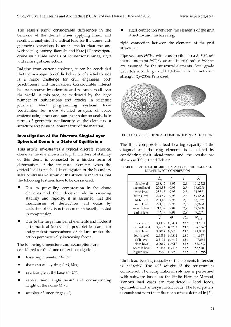
Investigation of the Discrete Single-Layer Spherical Dome in a State of Equilibrium
This article investigates a typical discrete spherical
dome as the one shown in Fig. 1. The loss of stability
of this dome is connected to a hidden form of
deformation of the structural elements when the
critical load
is
reached.
Investigation
of
the
boundary
state of stress and strain of the structure indicates that
the following features have to be considered:
Due to prevailing compression in the dome
elements and their decisive role in ensuring
stability and rigidity, it is assumed that the
mechanisms of destruction will occur by
exclusion of the bars that are most heavily loaded
in compression.
Due to the large number of elements and nodes it
is impractical (or even impossible) to search for
independent mechanisms of failure under the
action parametrically increasing forces.
The following dimensions and assumptions are
considered for the dome under investigation:
base ring diameter D=30m;
diameter of key ring dk =1,65m;
cyclic angle at the base = 15 ;
central semi angle α =50 and corresponding
height of the dome H=7m; number of inner rings n=7;
rigid connection between the elements of the grid
structure and the base ring;
rigid connection between the elements of the grid
structure.
Pipe sections
Ø83
х4
with
cross
‐section
area
А=9,93
сm
2
,
inertial moment I=77,64cm4 and inertial radius i=2,8cm
are assumed for the structural elements. Steel grade
S235JRH according to Е N 10219‐2 with characteristic
strength Ry=235MPa is used.
FIG. 1 DISCRETE SPHERICAL DOME UNDER INVESTIGATION
The limit compression load bearing capacity of the
diagonal and the ring elements is calculated by
considering their slenderness and the results are
shown in Table 1 and Table 2.
TABLE 1 LIMIT LOAD BEARING CAPACITY OF THE DIAGONAL
ELEMENTS FOR COMPRESSION
first level 283,45 9,93 2,8 101,2321second level 270,55 9,93 2,8 96,6250third level 257,48 9,93 2,8 91,9571
fourth level 244,87 9,93 2,8 87,4536fifth level 233,43 9,93 2,8 83,3679sixth level 223,93 9,93 2,8 79,9750
seventh level 217,08 9,93 2,8 77,5286eighth level 132,32 9,93 2,8 47,2571
first level 3,4192 0,5409 23,5 119,9081second level 3,2635 0,5717 23,5 126,7467third level 3,1059 0,6040 23,5 133,9074
fourth level 2,9538 0,6362 23,5 141,0374fifth level 2,8158 0,6662 23,5 147,694sixth level 2,7012 0,6918 23,5 153,3577
seventh level 2,6186 0,7105 23,5 157,5181eighth level 1,5961 0,8650 23,5 191,7595
i L A i
y R,
cr i N
Limit load bearing capacity of the elements in tension
is 221,69kN . The self weight of the structure is
considered. The computational solution is performed
with software based on the Finite Element Method.
Various load cases are considered – local loads,
symmetric and anti ‐symmetric loads. The load pattern
is consistent with the influence surfaces defined in [7].

7/27/2019 Combined Mechanisms of Collapse of Discrete Single‐Layer Spherical Domes
http://slidepdf.com/reader/full/combined-mechanisms-of-collapse-of-discrete-singlelayer-spherical-domes 4/9
www.seipub.org/scea Study of Civil Engineering and Architecture (SCEA) Volume 1 Issue 1 , December 2012
22
TABLE 2 LIMIT LOAD BEARING CAPACITY OF THE RING ELEMENTS
first level 353,48 9,93 2,8 126,2429second level 311,18 9,93 2,8 111,1357third level 265,18 9,93 2,8 94,7071
fourth level 216,03 9,93 2,8 77,1536fifth level 164,31 9,93 2,8 58,6821sixth level 110,64 9,93 2,8 39,5143
seventh level 55,65 9,93 2,8 19,8750eighth level 21,54 9,93 2,8 7,6929
first level 4,2639 0,3913 23,5 86,7537second level 3,7537 0,4781 23,5 105,9781third level 3,1988 0,5849 23,5 129,6605
fourth level 2,6059 0,7134 23,5 158,1615fifth level 1,9820 0,8648 23,5 191,7191sixth level 1,3346 1,0393 23,5 221,6873
seventh level 0,6713 1,2366 23,5 221,6873eighth level 0,2598 0,8650 23,5 221,6873
i L A i
y R,
cr i N
In order to determine the critical value of the load
parameter incrementally increasing loading is applied
with successive approximations for calculation of the
boundary equilibrium of the system in each load ‐step.
At a given stage of loading when an element reaches
its limit bearing capacity it is excluded from work and
in the next step of calculation its contribution is not
considered. This is repeated until the equilibrium of
the system is reached for this stage of loading without
the “excluded” elements. The study was conducted in
terms of geometric nonlinearity introduced by
accounting for P‐Δ effects, i.e. influence of normal
forces on the stiffness of the system. It is assumed that
the displacements increase after exclusion of elements
after reaching their capacity. The equilibrium
conditions are defined for the deformed shape of the
structure.
Analysis of the Results
First Load Case
The first load case is the local load shown in Fig. 2.
FIG. 2 LOAD CASE 1 ‐ LOCAL LOAD
It has initial value q1=1kN/m2 and is increased with
equal step. When the load reaches q8=8kN/m2 two
elements reach their capacity and are excluded from
the next calculation stage (see Fig. 3 and Fig. 5).
FIG. 3 FIRST AND FIFTH STAGE OF EXCLUSION OF ELEMENTS
In the next calculation steps progressive exclusion of 8, 33, 47 and in the end 12 elements occurs. This process
is illustrated in Fig. 5. When the load is q8=8kN/m2 total
of 102 elements reach their capacity. Deformed scheme
of the last stage of exclusion is illustrated in Fig. 4.
FIG. 4 LAST STAGE (FIFTH STAGE) OF EXCLUSION OF
ELEMENTS AND ITS CORRESPONDING DEFORMED SCHEME
FOR LOAD CASE 1
FIG. 5 NUMBER AND SEQUENCE OF BARS REACHING THEIR
CAPACITY FOR LOAD CASE 1
Second Load Case
In the second case, the load is applied in anti ‐
symmetric pattern (ratio 2:1) with respect to one of the
axis (for example, axis Y) of the dome, see Fig. 6. The
first elements reach their capacity at q4=4kN/m2. The

7/27/2019 Combined Mechanisms of Collapse of Discrete Single‐Layer Spherical Domes
http://slidepdf.com/reader/full/combined-mechanisms-of-collapse-of-discrete-singlelayer-spherical-domes 5/9
Study of Civil Engineering and Architecture (SCEA) Volume 1 Issue 1 , December 2012 www.seipub.org/scea
23
sequence of exclusion of elements at this stage of
loading is shown in Fig. 7 and Fig. 8. First to be
excluded are elements number 1 , which leads to
overloading of elements 2 . They are excluded from
the next stage, and this process continues until the
structure no longer fulfills its operational purpose. This promptly leads to overloading of consecutive
groups of elements, increasing the displacement and
destruction of the dome. The last stage of exclusion of
elements and the corresponding deformed scheme is
shown in Fig. 9. The process of successive exclusion is
progressive, resembling a domino effect. When load
q4=4kN/m2 is reached totally 94 elements (in 1st stage ‐
4, in 2d stage ‐ 16, in 3d stage – 74) are excluded.
FIG. 6 ANTI ‐SYMMETRICAL LOAD CASE 2
FIG. 7 I‐ST STAGE AND III‐RD STAGE OF EXCLUSION OF
ELEMENTS AND ITS CORRESPONDING DEFORMED SCHEME
FOR LOAD CASE 2
FIG. 8
NUMBER
AND
SEQUENCE
OF
BARS
REACHING
THEIR
CAPACITY FOR THE SECOND ANTI ‐SYMMETRICAL LOAD
CASE
FIG. 9 SECOND AND LAST STAGE (THIRD STAGE) OF
EXCLUSION OF ELEMENTS AND ITS CORRESPONDING
DEFORMED SCHEME FOR LOAD CASE 2
Third Load Case
In this case the load is localized between the sixth,
seventh and eighth level, see Fig. 10. Step load is
applied and the elements start reaching their capacity
at 13kN/m2.
FIG. 10 LOCAL LOAD CASE 3
In the first stage bars from the sixth and seventh inner
ring (48 in number) are excluded because of reaching
their capacity in compression, then at the second stage
elements are excluded from the fourth inner ring (in
tension), then from the fifth and eighth inner ring (in
compression). After these two stages static scheme of
the elements changes and they begin to work in
bending. In the third stage they are overloaded by the
bending moments occurring in them (144 in number ‐
the diagonal elements in the loaded area).
FIG. 11 SECOND STAGE OF THE EXCLUSION OF BARS
When the load is q13 = 13kN/m2 total of 264 elements (in
1st stage ‐ 48, in 2d stage – 72, in 3d stage – 144) are
excluded from the system. This process is illustrated in Fig. 11, Fig. 12 and Fig. 13.

7/27/2019 Combined Mechanisms of Collapse of Discrete Single‐Layer Spherical Domes
http://slidepdf.com/reader/full/combined-mechanisms-of-collapse-of-discrete-singlelayer-spherical-domes 6/9
www.seipub.org/scea Study of Civil Engineering and Architecture (SCEA) Volume 1 Issue 1 , December 2012
24
FIG. 12 I‐ST STAGE AND III‐RD STAGE OF EXCLUSION OF
ELEMENTS AND ITS CORRESPONDING DEFORMED SCHEME
FOR LOAD CASE 3
FIG. 13 NUMBER AND SEQUENCE OF BARS REACHING THEIR
BEARING CAPACITY FOR LOAD CASE 3
Fourth Load Case
In this case the load is localized in seventh and eighth
level as shown in Fig. 14.
FIG. 14 LOAD CASE 4
At 14kN/m2 the elements start reaching their capacity.
First elements from the eighth inner ring working
under compression are excluded (24 in number), then
in the second stage elements of the seventh inner ring
(in compression) are excluded, and in the third stage
elements of the fifth inner ring (in tension) and sixth
inner ring (in compression) reach their capacity.
After these three stages the static scheme of the
elements changes and they begin to work in bending as in the previous load case. In the fourth stage the
elements are overloaded bending moments (264 in
number ‐ the diagonal elements in loaded area).
Totally 360 elements (in 1st stage ‐ 24, in 2d stage – 24, in 3d stage – 48, in 4th stage – 264) are excluded at
q14=14kN/m2. This process is illustrated in Fig. 15, Fig.
16 and Fig. 17.
FIG. 15 THIRD STAGE OF THE EXCLUSION OF ELEMENTS AND
ITS CORRESPONDING DEFORMED SCHEME FOR LOAD CASE 4
FIG. 16 I‐ST STAGE AND IV‐TH STAGE OF EXCLUSION OF
ELEMENTS AND ITS CORRESPONDING DEFORMED SCHEME
FOR LOAD CASE 4
FIG. 17 NUMBER AND SEQUENCE OF ELEMENTS REACHING
BEARING CAPACITY FOR LOAD CASE 4
Fifth Load
Case
This local load case is shown in Fig. 18.

7/27/2019 Combined Mechanisms of Collapse of Discrete Single‐Layer Spherical Domes
http://slidepdf.com/reader/full/combined-mechanisms-of-collapse-of-discrete-singlelayer-spherical-domes 7/9
Study of Civil Engineering and Architecture (SCEA) Volume 1 Issue 1 , December 2012 www.seipub.org/scea
25
FIG. 18 LOAD CASE 5
When the value of the load is q10=9kN/m2 , two elements
lose stability and are excluded from the next
calculation stage. Consecutive exclusion of 9 elements
and then another 15, 78 and 38 occurs reaching total
number of 142 (see Fig. 19 and Fig. 20).
FIG. 19 I‐ST STAGE AND IV‐TH STAGE OF EXCLUSION OF
ELEMENTS AND ITS CORRESPONDING DEFORMED SCHEME
FOR LOAD CASE 5
FIG. 20 NUMBER AND SEQUENCE OF ELEMENTS REACHING
BEARING CAPACITY FOR LOAD CASE 5
The last stage of the exclusion of bars and its
corresponding deformed scheme is shown in Fig. 21.
FIG. 21 FINAL STAGE (FIFTH STAGE) OF EXCLUSION OF
ELEMENTS AND ITS CORRESPONDING DEFORMED SCHEME
FOR LOAD CASE 5
Sixth Load Case
In the sixth case, the load is applied in anti ‐symmetric
pattern (in ratio 3:1) with respect to one of the axis (for
example, axis Y) of the dome as illustrated in Fig. 22. At loading q4=4kN/m2 the elements start reaching their
capacity. First to lose stability are the elements with
number 1 , which leads to overloading of the
elements 2 (see Fig. 23 and Fig. 24), which are
excluded from the next stage. This continues until the structure no longer fulfills its operational purpose.
FIG. 22 LOAD CASE 6 – ANTI ‐SYMMETRIC LOADING
FIG. 23 I‐ST STAGE AND V‐TH STAGE OF EXCLUSION OF
ELEMENTS AND ITS CORRESPONDING DEFORMED SCHEME
FOR LOAD CASE 5
FIG. 24 NUMBER AND SEQUENCE OF BARS REACHING
BEARING CAPACITY FOR LOAD CASE 6
The last stage of the exclusion and its corresponding
deformed scheme are shown in Fig. 25. Finally under
loading of q4=4kN/m2 total of 131 elements are
excluded from the structural system.

7/27/2019 Combined Mechanisms of Collapse of Discrete Single‐Layer Spherical Domes
http://slidepdf.com/reader/full/combined-mechanisms-of-collapse-of-discrete-singlelayer-spherical-domes 8/9
www.seipub.org/scea Study of Civil Engineering and Architecture (SCEA) Volume 1 Issue 1 , December 2012
26
FIG. 25 THE LAST STAGE (FIFTH STAGE) OF EXCLUSION OF
ELEMENTS AND ITS CORRESPONDING DEFORMED SCHEME
FOR LOAD CASE 6
Conclusions
Studies conducted under six different load cases show
different forms (mechanisms) of failure. Apparently,
the most unfavorable load configurations are anti ‐
symmetric ones. Limit load of the local symmetric load
configuration (third and fourth case) have larger value,
thus reflecting a much larger symmetrical stiffness in
comparison to the behavior under the anti ‐symmetric
load configuration. In the symmetric local load
configurations, elements directly under the load
contour are affected. The limit value of the applied
load decreases when for anti ‐symmetric distribution
larger area of the dome is covered. This leads to
exclusion of large number of meridian elements at the
base. Characteristic feature of all load cases is the
domino effect where the limit load is reached by
progressive exclusion of groups of elements at a time.
Based on this research the following conclusions can
be formulated:
1) Typical for the dome structure is the elasto ‐plastic behavior.
2) Progressive collapse is observed when
reaching the limit load.
3) The limit load is the lowest for anti ‐
symmetrical load patterns. For local load
configurations over small area, local failure
under larger limit load is observed. By
enlarging the loaded area the value of the limit
load decreases.
4)
Overloading and subsequent failure is observed for the elements in proximity of the
local load stamp.
REFERENCES
Abedi K., Parke G., ”Progressive Collaps of Single ‐Layer
Braced Domes.”, Int. Journal of Space Structures, Vol. 11,
No 3, 1996, pp. 291‐305.
Bankov B. P., ”Statics of Structures Part I and Part II.”,
UACEG, Sofia, 2001.
Bankov B. P., ”Theory of Elasticity, Stability and Dynamics
of Elastic Systems.”, UACEG, Sofia, 2004.
Bankov B., Pavlova U., ”Finite element method in structural
mechanics.”, UACEG, Sofia, 1996.
Bobev T., Ganev T., Rangelov R., Pavlova U., Boichev I.,
Markov I., Krystev C., Popov A., Bonev Z., Vasilev T.,
Levi I., ”Stability and Dynamics of Structures ‐ Guidance
for solving problems.”, Technics, Sofia, 1994.
Borri C., Chiostrini S., ”Numerical Approaches to the
Nonlinear Stability Analysis of Single Layer Reticulated
and Grid ‐Shell Structures.”, Int. Journal of Space
Structures, Vol. 7, No. 4, 1992, pp. 285‐297.
Dubina D., ”Computation Models and Numerical Solution
procedures for Nonlinear Analysis of Single Layer
Laticce Shell.”, Int. Journal of Space Structures, Vol. 7, No.
4, 1992, pp. 321‐333.
El‐Sheikh A. I., ”Sensitivity of Space Trusses to Sudden
Member Loss.”,
Int.
Journal
of
Space
Structures,
Vol.
12,
No 1, 1997, pp. 31‐41.
Gioncu V., Balut N., ”Instability Behavior of Single Layer
Reticulated Shell.”, Int. Journal of Space Structures, Vol.
7, No. 4, 1992, pp. 243‐250.
Gioncu V., ”Buckling of Reticulated Shell: State of‐the Art.”,
Int. Journal of Space Structures, Vol. 10, 1995, pp. 1‐37.
Holzer M., Wu C., Tissaoui J., ”Finite Element Stability
Analysis of Glulam Dome.”, Int. Journal of Space
Structures, Vol. 7, No. 4, 1992, pp.353 ‐361.
Handruleva A., Bankov B., Kazakov К ., Matuski
V., ”Influence surfaces of discrete spherical domes.”,
Proceedings VSU 2012, Vol. 1, Sofia, pp. 47‐53.
Ikarashi K., Kato S., ”Elasto ‐Plastic Dynamic Buckling
Analysis of Reticular Domes Subjected to Earthquake
Motion.”, Int. Journal of Space Structures, Vol. 12, No.
3&4, 1997, pp. 205‐215.
Králik, J., ”Reliability Analysis of Structures Using Stochastic
Finite Element Method.”, Published by STU Bratislava,
2009, 143 pp., ISBN 978‐80‐227‐3130‐0.
Kato S., Yamada S., Takashima H., Shibata R., ”Buckling
Stress of a Member in a Rigidly Jointed Single ‐Layer
Reticular Dome.”, Proceedings of the IASS, Vol. III
Copenhagen, 1991, pp. 109‐116.
Kato S., ”Study on the Buckling Behavior of Semi ‐Rigidly
Jointed Latticed Dome of Single Layer.”, Proceedings of
the IASS, Vol. 4, Madrid, 1989.
Kazakov К . S., ”Theory of Elasticity, Stability and Dynamics
of Structures.”, Academic Publishing House Prof. Drinov,
Sofia, 2010.
7/27/2019 Combined Mechanisms of Collapse of Discrete Single‐Layer Spherical Domes
http://slidepdf.com/reader/full/combined-mechanisms-of-collapse-of-discrete-singlelayer-spherical-domes 9/9
Study of Civil Engineering and Architecture (SCEA) Volume 1 Issue 1 , December 2012 www.seipub.org/scea
27
Kazakov К . S., ”Finite Element Method for modeling of
building constructions.”, Academic Publishing House
Prof. Drinov , Sofia, 2010.
Levy R., Hanaor A., Rizzuto N., ”Experimental Investigation
of Prestresing in Double ‐Leyer Grids, Int. Journal of
Space Structures, Vol. 9, No 1, 1994, pp. 21‐25.
Murakami, Heki, ”On the Analysis of Elastic Buckling of
Single Layer Latticed Domes with Regular Hexagonal
Plan under Gravity Load.”, Proceedings of the IASS, Vol.
III Copenhagen, 1991, pp. 101‐108.
Morris N., ”Application of a Koiter ‐type. Theory to Buckling
of Lattice Domes.”, Int. Journal of Space Structures, Vol.
7, No. 4, 1992, pp.335 ‐343.
Rothert H. Gebeken N., ”On Numerical Results of
Reticulated Shell Buckling, Int. Journal of Space
Structures, Vol. 7, No 4, 1992, pp. 299‐319.
Sumec J., ”General Stability Analysis of Lattice Shells by
Continuum Modeling.”, Int. Journal of Space Structures,
Vol. 7, No. 4, 1992, pp. 275‐283.
Sumec J., ”Regularne mriezkove dosky a skrupiny.”,
Bratislava, 1984.
Saka T., Taniguchi Y., ”Post ‐Buckling Behavior of Square ‐on ‐
Diagonal Double ‐Layer Grids Constructed by Bolted
Jointing System.”, Proceedings of the IASS, Vol. III
Copenhagen, 1991, pp. 199‐206.
Suzuki T., Ogawa T., Ikarashi K., ”Elasto ‐Plastic Buckling
Analysis of Rigidly Jointed Single Layer Reticulated
Domes.”, Int. Journal of Space Structures, Vol. 7, No. 4,
1992, pp. 363‐367.
Smith E., Nguyen T., ”Buckling of Double Layer Grid Edge
Members, Int. Journal of Space Structures.”, Vol. 12, No 2,
1997, pp. 81‐87.
Saka T., ”Approximate Analysis method for Post ‐Buckling
Behavior of Double ‐Layer Space Grids Construction by a
Bolted Jointing System.”, Proceedings of the IASS, Vol. 4,
Madrid, 1989.
See T., McConnel R., ”Large Displacement Elastic Buckling
of Space Structures, Journal of Structural Engineering,
ASCE 112(5), 1986, pp. 1052‐1069.
Suzuki T., Ogawa T., Ikarashi K., ”Elasto ‐Plastic Buckling
Analysis of Rigidly Jointed Single Layer Reticulated
Domes with Random Initial Imperfections, Int. Journal of
Space Structures, Vol. 7, No. 4, 1992, pp. 265‐273.
Ueki T., Kato S., Kubodera I., Mukaiyama Y., ”Study on the
Elastic and Elasto ‐Plastic Buckling Behavior of Single
Layered
Domes
Composed
of
Members
having
Axial
and Bending Springs at Both Ends.”, Proceedings of the
IASS, Vol. III, Copenhagen, 1991, pp. 93‐100.
Vasek M., ”Non ‐Linear Small Strain ‐Separate Effects
Solution of 3D Beam System.”, Computational
Mechanics, Barcelona, Spain, 1998.
Yamada S., Takeuchi A., Tada Y., Tsutsumi
K., ”Imperfection ‐Sensitive Overall Buckling of Single ‐
Layer Lattice Domes.”, Journal of Engineering Mechanics,
Vol. 127, No. 4, April 2001, pp. 382‐386.
Anita K. Handruleva was born in
Burgas, Bulgaria in 1985. She is assistant
professor in the field of Structural
mechanics in the department
Mechanics , Higher School of Civil
Engineering “L. Karavelov”, Sofia, Bulgaria. She is author of two books and
more than 25 research papers in the field
of FEM computational modelling and the Structural
mechanics.
Assist.
prof.
Handruleva
is
member
of
IASS,
IABSE and others professional societies.
Vladimir D. Matuski was born in
Kustendil, Bulgaria in 1975. He is
assistant professor in the field of
Structural mechanics in the structural
mechanics dept. of VSU “Luben
Karavelov”, Sofia, Bulgaria. He is
coauthor of two books and more than 10
research papers in the field of the
Structural mechanics. Assist. prof. Matuski is member of
IASS and IABSE.
Konstantin S. Kazakov was born in Sofia, Bulgaria in 1966. He is professor in
the field of Structural mechanics and
Numerical methods in engineering in the
structural mechanics dept. of VSU
“Luben Karavelov”, Sofia, Bulgaria. He is
author of five books and more than 140
research papers in the field of the Structural mechanics and
the FEM computational technology. Prof. D.Sc. Kazakov is
member of several professional societies.