Embed Size (px)
Citation preview

General rights Copyright and moral rights for the publications made accessible in the public portal are retained by the authors and/or other copyright owners and it is a condition of accessing publications that users recognise and abide by the legal requirements associated with these rights.
Users may download and print one copy of any publication from the public portal for the purpose of private study or research.
You may not further distribute the material or use it for any profit-making activity or commercial gain
You may freely distribute the URL identifying the publication in the public portal If you believe that this document breaches copyright please contact us providing details, and we will remove access to the work immediately and investigate your claim.
Downloaded from orbit.dtu.dk on: Apr 24, 2020
Combination of Synchronous Condenser and Synthetic Inertia for Frequency StabilityEnhancement in Low Inertia Systems
Nguyen, Ha Thi; Yang, Guangya; Nielsen, Arne Hejde; Jensen, Peter Højgaard
Published in:I E E E Transactions on Sustainable Energy
Link to article, DOI:10.1109/TSTE.2018.2856938
Publication date:2018
Document VersionPeer reviewed version
Link back to DTU Orbit
Citation (APA):Nguyen, H. T., Yang, G., Nielsen, A. H., & Jensen, P. H. (2018). Combination of Synchronous Condenser andSynthetic Inertia for Frequency Stability Enhancement in Low Inertia Systems. I E E E Transactions onSustainable Energy, 10(3), 997 - 1005. https://doi.org/10.1109/TSTE.2018.2856938

1949-3029 (c) 2018 IEEE. Translations and content mining are permitted for academic research only. Personal use is also permitted, but republication/redistribution requires IEEE permission. Seehttp://www.ieee.org/publications_standards/publications/rights/index.html for more information.
This article has been accepted for publication in a future issue of this journal, but has not been fully edited. Content may change prior to final publication. Citation information: DOI 10.1109/TSTE.2018.2856938, IEEETransactions on Sustainable Energy
1
Combination of Synchronous Condenser andSynthetic Inertia for Frequency Stability
Enhancement in Low Inertia SystemsHa Thi Nguyen, Student Member, IEEE, Guangya Yang, Senior Member, IEEE, Arne Hejde
Nielsen, Senior Member, IEEE, and Peter Højgaard Jensen
Abstract—Inertia reduction due to high-level penetration ofconverter interfaced components may result in frequency stabilityissues. The paper proposes and analyzes different strategiesusing synchronous condenser (SC), synthetic inertia (SI) of windpower plant, and their combination to enhance the frequencystability of low inertia systems under various scenarios and windconditions. Furthermore, one of the SC models includes hardwareof automatic voltage regulator (AVR) for better representation ofthe reality is implemented. The simplified Western Danish powersystem simulated in real time digital simulator (RTDS) is used asa test system of low inertia to demonstrate the effectiveness of thestrategies. The comparative results show that the combination ofSC with AVR hardware-in-the-loop test and SI offers a betterimprovement not only on frequency stability (rate of changeof frequency and frequency deviation) but also on the systemsynchronism under various operating conditions.
Index Terms—Frequency stability, low inertia systems, syn-chronous condenser, synthetic inertia, wind power.
I. INTRODUCTION
W ITH the replacement of conventional generation bypower electronic-based generation such as wind power
plants, photovoltatics plants, and importing high-voltage directcurrent (HVDC) links, the significant inherent rotational inertiaproperty of traditional power plants is displaced by a smalleror no rotational inertia of converter interfaced generation.Therefore, high-level power electronic-based generation pene-tration makes the system inertia reduce that leads to the systemfrequency more vulnerable and probable frequency instabilityunder severe disturbances.
There have been many researchers considering the impactof low inertia on power system stability and operation becauseof high renewable energy penetration level [1]–[3]. In [1], aresearch related to system inertia and the challenge in the sys-tem operation due to the inertia reduction are investigated. Thestudy proposes using storage devices or inertia of converterconnected generation as a solution for low inertia systems.Maintaining sufficient inertia in the system to guarantee op-erational security is a main challenge of the Nordic powersystem [2]. The low inertia effect on power system operationand stability with high converter-connected wind turbine and
H. T. Nguyen, G. Y. Yang and A. H. Nielsen are with the Center for ElectricPower and Energy, Department of Electrical Engineering, Technical Universityof Denmark, Kongens Lyngby, DK-2800, Denmark (e-mail: (thangu, gyy,ahn)@elektro.dtu.dk, [email protected])
P. H. Jensen is with Energy Automation, Siemens A/S, 2750 Ballerup,Denmark (e-mail: peter [email protected])
photovoltaic penetration level is analyzed in [3]. The paperdemonstrates that system inertia becomes heterogeneous andfrequency dynamics are faster in power systems with lowinertia. Recently, 1200 MW photovoltaic resource interruptionincident in the Southern California system is occurred due tolow system frequency condition that activates inverters tripbased on the instantaneous frequency measurement during afault [4]. Consequently, the low inertia issue has been generallyrecognized.
To improve the frequency stability, transmission systemoperators (TSOs) have issued grid codes to the participationof wind power plants (WPPs) in frequency control [5]. Inaddition, the role and potential ability of WPPs for supportingfrequency control have been investigated in [6] that providesforeseeable ideas for further research work on WPPs. Recentliterature proposed strategies on implementing inertial supportof WPPs, the so-called synthetic inertia (SI), most of thempropose a supplementary control into active power loop thatis activated during frequency changes. It can be classifiedinto two main categories. The first one attempts to mimic theinertial response of conventional power plants [7], [8] that usesdf/dt as an input signal, while the second one takes frequencydeviation as an input signal with fast response time [9], [10].The authors in [11] use the combination of the two controlstrategies to provide inertial response for WPP. An ancillarycontrol signal proportional to df/dt and frequency deviationis used to increase/decrease the electric power of WPP.
A number of authors have paid more attention to theactivation schemes instead of control methods for SI im-plementation [12], [13]. A coordination of inertial responseand grid event detector using a demanded inertia responseand df/dt calculation trigger are studied in [12], whereasdifferent activation methods are proposed and analyzed in [13]that focuses on trigger schemes without coordinated with thecontrol. Based on the above-mentioned literature, a fulfilledcontrol strategy investigated both the control method and theactivation scheme for SI of WPPs has not done yet. Moreover,the synthetic inertia from WPPs is not fast enough to react insevere disturbances.
Synchronous condenser (SC) has been playing an importantrole in reactive power compensation and keeping voltagestability in power systems for a couple of decades [14].By varying the field excitation current, SC can operate atover-excited or under-excited modes to supply/absorb reactivepower to/from the network that can control smoothly the

1949-3029 (c) 2018 IEEE. Translations and content mining are permitted for academic research only. Personal use is also permitted, but republication/redistribution requires IEEE permission. Seehttp://www.ieee.org/publications_standards/publications/rights/index.html for more information.
This article has been accepted for publication in a future issue of this journal, but has not been fully edited. Content may change prior to final publication. Citation information: DOI 10.1109/TSTE.2018.2856938, IEEETransactions on Sustainable Energy
2
voltage or keep the system power factor at a specified level.SC can also support the short-circuit power to the networkthat can improve system interconnections, facilitates systemprotection and enhances the operation of modern power elec-tronics installations [15]. Furthermore, using SC for decreasingunder frequency load shedding is investigated in [16] and ainteraction between active power and reactive power channelsof synchronous condensers to improve primary frequencycontrol is studied in [17].
Completely different from WPPs, SC is an alternator thatcan provide inherently inertial response due to the electrome-chanical coupling with the grid. The kinetic energy stored inits rotating mass can naturally counteract the frequency changeduring disturbances.
From the literature review, the difference between SC andSI in terms of frequency support is not very well clarified.In this paper, synchronous condenser and SI of WPPs areinvestigated and clearly shown for the frequency stability im-provement of low inertia systems. Firstly, usage SC providingthe inherent rotating energy to support inertial response thathelps primary control has more time to react during systemfrequency changes. The SC model includes a real automaticvoltage regulator (AVR) system that is interfaced with thesimulation through hardware-in-the-loop (HiL). HiL providesan efficient real-time control and a safe environment wheretests can focus on the functionality of the controller andverify all dynamic conditions of the system, which is hardto implement in real devices [18], [19]. During HiL test, thephysical system of AVR interfaces with the rest of SC and thegrid that are simulated in real-time digital simulator (RTDS),and the outputs of the simulation imitate the actual outputof the physical AVR system. Secondly, a SI controller ofWPPs and its activation scheme are proposed. The differenceof inertia characteristic between SC and SI for the frequencycontrol is analyzed. Finally, a combination of SC and SIis examined that shows a better performance not only infrequency stability enhancement but also in system frequencysynchronism. These methods are demonstrated on the futureWestern Danish renewable-based (DK1) system to analyzetheir performance during disturbances. Different scenariosand wind speed conditions are investigated to examine theeffectiveness of these approaches.
The remaining part of the paper is organized as follows.Section II introduces the system configuration, system fre-quency characteristics, SC with AVR HiL testing, and controldesign for SI of WPPs. The comparative results of differentscenarios and wind speed conditions using various strategiesare analyzed and discussed in section III. Some specificimportant conclusions are drawn in section IV.
II. FREQUENCY STABILITY ENHANCEMENT USING SC ANDSI OF WPPS
In this section, the system configuration of DK1 systemthat is used as a low inertia system background is firstlydepicted. After that, the system frequency characteristic isclearly analyzed. Finally, the AVR HiL testing model of SCand control design for SI of WPPs are investigated.
TJE
GERMANY
NJVB2,3~
Sweden
VHA
TRI
MKS SSVB3,4
~
~
EDR
ESVB3
FVO
~
FYVB7FGD
LAG
SVS
VKE
REV
KAS
~
FER
SKVB3
AHA
22/0.69 kV
VW
0.69/22 kV
VW
VSC-HVDC Link, 700 MW, 350 kV
~
VSC-HVDC Link: 700 MW, 320 kV
~
Netherlands
~
~
~
SC2
SC1
SC3
LCC-based HVDC link: 600 MW, 400 kV
CDC VDC
2 LCC-based HVDC link: 740 MW, 285 kV
CDC VDC
3 LCC-based HVDC link: 1050 MW, 250 kV
CDC VDC
~
AHA 400 MW
Norway
MAL
NVV
KIN
IDU
ASR
0.69/22 kV
VW
~
KAE
HRB 200 MW
HRC 400 MW
HRA 169 MW
SHE
VW
ONWF
DFIG-based OFWF
DFIG-based OFWF
PMSG-based OFWF
Norway
Fig. 1. Single-line diagram of 400 kV Western Danish renewable-basedsystem in 2020.
A. System Configuration
Fig. 1 shows the DK1 system in 2020 that is using a major-ity of renewable energy and interconnecting to the neighboringcountries through HVDC links. This system is based on thecurrent DK1 system [20] adding more 400 MW offshore windfarm (HRC or HR3) and 700 MW Voltage-sourced converter(VSC) HVDC interconnection to the Netherlands (COBRAcable) that are operating in 2017 and in 2019, respectively. TheGerman grid is modeled by a large synchronous generator with7 s inertia constant and a load. The frequency control supportof the German grid is adjusted proportional to the power ex-change. There are three synchronous condensers (the markedred in Fig. 1) connected at three line-commutated converter(LCC) HVDC terminals with the detail parameters in TableI. The AVR of synchronous condenser located at bus FGDuses real control system to evaluate its performance duringdisturbances. There are three aggregate offshore wind farms(OFWFs), and one aggregate onshore wind farm (ONWF) asshown in Fig. 1.
TABLE ISYNCHRONOUS CONDENSER PARAMETERS.
SCs LocationSrated Vrated Qmin Qmax H
(MVA) (kV) (Mvar) (Mvar) (s)SC1 VHA 200 12 -100 150 2SC2 TJE 250 13 -120 200 2.2SC3 FGD 270 15.75 -144 242 2.5
B. System Frequency Characteristics
Inertia is defined as the resistance of a physical objectto changes in its state and position, consisting of its speedand direction [1]. Applying to an electrical power system,the physical objects are the rotating machines (generators,motors, etc.) connected directly to the power system and theresistance to the change in rotational speed is expressed bythe moment of inertia of their rotating mass. It is assumedthat only synchronous machines (generator and condenser)contribute to the system inertia in the respect of physics. The

1949-3029 (c) 2018 IEEE. Translations and content mining are permitted for academic research only. Personal use is also permitted, but republication/redistribution requires IEEE permission. Seehttp://www.ieee.org/publications_standards/publications/rights/index.html for more information.
This article has been accepted for publication in a future issue of this journal, but has not been fully edited. Content may change prior to final publication. Citation information: DOI 10.1109/TSTE.2018.2856938, IEEETransactions on Sustainable Energy
3
Fig. 2. The dependence of system inertia on maximum ROCOF anddisturbance size.
system inertia of a power system is referred to the nominalapparent power of synchronous machines that is defined by
Hsys =
N∑i=1
(SniHi)
Ssys(1)
where Ssys is selected equal to the total load of system; Nis the number of synchronous machines; and Sni and Hi
are the nominal apparent power and the inertia constant ofi-th synchronous machine, respectively. The system inertiadepends on the number of operating rotating machines andthe inertia constant of each machine.
A sudden change in load or generation causes a changein the generation-demand equilibrium. The system inertiaconstant plays a vital role in the first few seconds, afterthat primary control picks up the frequency deviation bycontrolling the governor to return the frequency to acceptableoperating value within 30 s. A higher inertia constant resultsin a lower rate of change of frequency (ROCOF), which givestime to the primary control regulating the power output.
The initial ROCOF that is determined by the size of thepower imbalance and the system inertia is expressed by
ROCOF =f0
2Hsys
∆P
Ssys(2)
where ∆P is the disturbance size; f0 is the nominal systemfrequency. Let define H1 and ROCOF1 are the system inertiaand ROCOF of the current system, and H2 and ROCOF2 arethose of the future system that uses a majority of renewableenergy, respectively. Hence, ROCOFs of these two systems fora given disturbance are described based on (2) as follows:
ROCOF1 =f0
2H1
∆P
Ssys(3)
ROCOF2 =f0
2H2
∆P
Ssys(4)
From (3) and (4) gives:
H2 = H1ROCOF1
ROCOF2(5)
From (5), when the maximum ROCOF that is imposedby TSOs is set, the minimum system inertia of the futuresystem for a given disturbance is determined based on the
current system, which beyond it ROCOF of the future systemwould be over the permissible value. The minimum systeminertia enables the system withstand a certain disturbancewithout exceeding a certain ROCOF is shown in Fig. 2. Thegeneral evaluation of minimum inertia will cover disturbancesize from 5% to 30% of the system load, and maximumROCOF between 0.5 and 2.5 Hz/s [21]. As can be seen clearlythat there is a reverse correlation between minimum systeminertia and maximum ROCOF, the higher maximum ROCOFis allowed, the lower minimum system inertia is required. Onthe contrary, a positive one exists between minimum systeminertia and disturbance size, a larger disturbance requires ahigher system inertia in order to the system frequency is notover the permissible maximum ROCOF.
The frequency deviation is regulated by the available fre-quency containment reserves. In the test system, it dependson the available primary control headroom of the online syn-chronous generators (SGs) and the German grid. The WesternDanish system is synchronized to the Continental Europeansystem where its primary reserve is designed in order to thesystem frequency deviation remains within a certain range forordinary as well as severe contingencies [22].
The system primary regulation constant for the entire systemin MW/Hz is determined by
Ksys =N∑i=1
Ki =N∑i=1
Sni
Rif0(6)
where Ki and Ri are regulation constant and droop gain ofi-th synchronous generator, respectively. The system primaryregulation constant determines how much active power sup-plies/absorbs against frequency changes. Ksys is normally keptfix and decided by the primary reserve.
When the system operates with high renewable energy pro-duction, high importing HVDC links, and phasing out of con-ventional power plants, the system inertia reduces significantlythat makes the frequency dynamics faster and more vulnerable.This may result in an activation of under frequency loadshedding or ROCOF-operated protection relays for trippingtransmission lines. As a result, the system freely gets split andmore challenging to operate. Cascading failure or even systemblackout may therefore occur. In the low inertia operatingsituation, some possible solutions TSOs could be implementedin form of grid codes such as the minimum system inertiarequirement, limiting the power output of large importingHVDC interconnections, or HVDC emergency power controlto guarantee for the operational stability of the system.
Regarding the load model, the lately proposed WesternElectricity Coordinating Council (WECC) composite loadmodel can better represent the dynamic behavior of loadsduring faults [23-24], which is the advantage of WECC modelcompared to static load models. However, the inertia of themotor in the model may not represent the worst case for thefrequency stability study. Therefore, the paper uses the ZIPload model instead, where the parameters of the model arebased on the information provided by the operators. A ZIPload model as a function of frequency variation and voltagemagnitude that is called voltage & frequency dependent load

1949-3029 (c) 2018 IEEE. Translations and content mining are permitted for academic research only. Personal use is also permitted, but republication/redistribution requires IEEE permission. Seehttp://www.ieee.org/publications_standards/publications/rights/index.html for more information.
This article has been accepted for publication in a future issue of this journal, but has not been fully edited. Content may change prior to final publication. Citation information: DOI 10.1109/TSTE.2018.2856938, IEEETransactions on Sustainable Energy
4
(V&FDL) model is implemented in this paper, yielding to thefollowing equation
PL = P0(1 + kPf∆f)(pp + pcV
V0+ pz(
V
V0)2) (7)
QL = Q0(1 + kQf∆f)(qp + qcV
V0+ qz(
V
V0)2) (8)
where PL and QL are the active power and reactive powerof the load (pu); P0 and Q0 are the rated active power andreactive power of the load (pu); V0 and V are the nominal andactual voltage magnitude at the load bus (pu); f0 and ∆f arethe nominal frequency and frequency deviation (pu); kPf andkQf are the frequency characteristic coefficients; pp and qp arethe portion of total load proportional to constant active powerload; pc and qc are the portion of total load proportional toconstant current load; pz and qz are the portion of total loadproportional to constant impedance load, respectively.
C. AVR hardware in the loop for synchronous condenser
The AVR of the biggest capacity SC (SC3) located at busFGD is implemented HiL, whereas the other ones use modifiedIEEE standard model of AC7B excitation system, which isincluded in the RTDS library to have a similar response withthe AVR used in HiL.
The entire grid and SC model are simulated in RTDS withthe dash blue bound, while AVR system is implemented HiLwith the dash red one as shown in Fig. 3. RTDS sends three-phase currents and voltages of the SC terminal, as well asthe frequency and voltage measured at the busbar to AVR,whereas AVR set point (AVR SP) is sent to RTDS.
The AVR is implemented based on PID controller of theAVR system of IEEE AC7B excitation model as shown inFig. 4 that is modeled in VisSim software in PC1 and thenprogrammed on PLC S7-400. Furthermore, S7-400 integrateswith supervisory control and data acquisition (SCADA) systemon PC2 using WinCC via IEC 104 standard for continuousmonitoring, data storage, control, and analysis. The SC be-havior can be captured over a long real-time period and usedfor further analysis.
S7-1500
AVR – S7-400H
EXCITER
SC
,busV f
1V
1I
AVR SP
HiL
RTDSCB
ON GRID
GRID
MEASUREMENT TRANSFORMER
PC1: VisSim PC2: WinCC
DP
OPC IEC 104
Fig. 3. Hardware in the loop testing setup for AVR system.
maxRV
+
+CV
+
1 + sTD
sKDKPKI
s+ +
minRV
RVKP
KI
s+
AV
maxAV
minAV
KF2
1 + sTE
1
SE(VE)
KE
KD
f(IN)
VE
KCIFD
fdI
fdE+
-
+
++
+
TpVK
-
FELVK
EV
minEV
maxEV
refV
UELV
-
PSSV
Frequency converterExciter
Diode bridge
AVR
Fig. 4. IEEE AC7B excitation system.
D. Synthetic inertia of WPPs
Because the replacement for traditional generation byrenewable-based generation may results in more challengingfor the system frequency stability, TSOs have issued gridcodes to all grid-connected generators. For instance, WPPswith rated power above 10 MW in the UK, above 50 MWin the continental European grid, and above 5 MW in Irelandmust be equipped with a control system for frequency response[5], [25]. To satisfy the grid connection requirement, SIcontroller for WPPs that mimics the inertial response behaviorof the conventional power plant during power imbalances isextremely necessary.
Fig. 5 shows the proposed synthetic inertia controller thatincludes two control loops, the first one takes df/dt asthe input to create an additional signal T1, the second onegenerates an extra signal T2 from frequency deviation input. Inorder to avoid competing control effect, the proposed methodswitches the reference from Tref of MPPT control to TSI ofthe proposed scheme during the inertia response. The outputof SI can be expressed as follows:
TSI = Kindf
dt−Kdroop∆f + Trefp (9)
where Trefp is the reference from MPPT corresponding topre-disturbance rotor speed that is stored on the system data.
A low-pass filter is used to eliminate the measurementnoise. Furthermore, a dead band (± 0.015 Hz) is deployedto avoid the participation of the synthetic inertia control on asmall frequency variation. A high-pass filter (HPF) is appliedto guarantee that the ∆f control loop does not contributewhen the system frequency reaches a new equilibrium andthe turbine can recover the operating speed.
It is important to select properly the values of Kin andKdroop. Otherwise, it may cause a poor performance for thecontroller. Kin is proportional to df/dt control loop, a highKin value may result in over ramping up limit of turbinespeed that can destroy the mechanical part of turbine. Kdroop
is the gain of ∆f control loop, a high Kdroop selection may
meaf1
1 + sT1
ddt
-Kin
-
+reff Kdroop
+
+
- 0.15
0.15
f
min,actf Comparator
x
f1 + sT2
sT2
T1
T2
HPF
A
refpT
+
-extT
,mea rmeaf
Ramp rate
refTMPPT
r
ConverterSIT
Fig. 5. Synthetic inertia controller of WPP.
1949-3029 (c) 2018 IEEE. Translations and content mining are permitted for academic research only. Personal use is also permitted, but republication/redistribution requires IEEE permission. Seehttp://www.ieee.org/publications_standards/publications/rights/index.html for more information.
This article has been accepted for publication in a future issue of this journal, but has not been fully edited. Content may change prior to final publication. Citation information: DOI 10.1109/TSTE.2018.2856938, IEEETransactions on Sustainable Energy
5
Germany
Sweden
Norway
DK2
Netherlands
1930 MW
700 MW
1000 MW
740 MW
600 MW
CP : 873 MW
W & C : 3269 MW
Load : 2936 MW
(a)
Germany
Sweden
Norway
DK2
Netherlands
2800 MW
700 MW
700 MW
740 MW
600 MW
CP : 750 MW
W & C : 3269 MW
Load : 3957 MW
(b)
Germany
Sweden
Norway
DK2
Netherlands
3050 MW
500 MW
500 MW
600 MW
600 MW
CP : 0 MW
W & C : 3269 MW
Load : 3957 MW
(c)
Germany
Sweden
Norway
DK2
Netherlands
1550 MW
500 MW
1000 MW
600 MW
600 MW
CP : 0 MW
W & C : 3269 MW
Load : 3957 MW
(d)
Germany
Sweden
Norway
DK2
Netherlands
2800 MW
700 MW
1000 MW
740 MW
600 MW
CP : 0 MW
W & C : 2395 MW
Load : 2055 MW
(e)
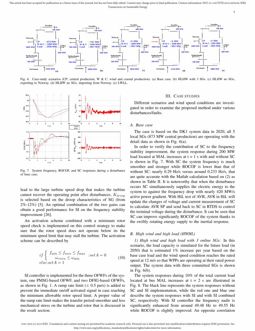
Fig. 6. Case-study scenarios (CP: central production, W & C: wind and coastal production). (a) Base case. (b) HLHW with 3 SGs. (c) HLHW no SGs,exporting to Norway. (d) HLHW no SGs, importing from Norway. (e) LWLL.
Fig. 7. System frequency, ROCOF, and SC responses during a disturbanceof base case.
lead to the large turbine speed drop that makes the turbinecannot recover the operating point after disturbances. Kdroop
is selected based on the droop characteristics of SG (from2%-12%) [5]. An optimal combination of the two gains canobtain a good performance for SI on the frequency stabilityimprovement [26].
An activation scheme combined with a minimum rotorspeed check is implemented on this control strategy to makesure that the rotor speed does not operate below its theminimum speed limit that may stall the turbine. The activationscheme can be described by
if
{fmin ≤ fmea ≤ fmax
ωrmea ≤ ωmin:setA = 0
else:setA = 1(10)
SI controller is implemented for the three OFWFs of the sys-tem, one PMSG-based OFWF, and two DFIG-based OFWFs,as shown in Fig. 1. A ramp rate limit (± 0.5 pu/s) is added toprevent the immediate on/off activated signal in case reachingthe minimum allowable rotor speed limit. A proper value ofthe ramp rate limit makes the transfer period smoother and lessmechanical stress on the turbine and rotor that is discussed inthe result section.
III. CASE STUDIES
Different scenarios and wind speed conditions are investi-gated in order to examine the proposed method under variousdisturbances/faults.
A. Base case
The case is based on the DK1 system data in 2020, all 5local SGs (873 MW central production) are operating with thedetail data as shown in Fig. 6(a).
In order to verify the contribution of SC to the frequencystability improvement, the system response during 200 MWload located at MAL increases at t = 1 s with and without SCis shown in Fig. 7. With SC the system frequency is muchsmoother and stronger while ROCOF is lower than that ofwithout SC: nearly 0.29 Hz/s versus around 0.233 Hz/s, thatare quite accurate with the Matlab calculation based on (2) asshown in Table II. It is noteworthy that when the disturbanceoccurs SC simultaneously supplies the electric energy to thesystem to against the frequency drop with nearly 420 MW/sactive power gradient. With HiL test of AVR, AVR in HiL willupdate the changes of voltage and current measurement of SCto calculate AVR SP and send back to SC in RTDS to controlthe terminal voltage during the disturbance. It can be seen thatSC can improve significantly ROCOF of the system thanks tothe swiftly rotating energy supply to the inertial response.
B. High wind and high load (HWHL)
1) High wind and high load with 3 online SGs: In thisscenario, the load capacity is simulated for the future load (in2050) that is estimated 1% increase per year based on thebase case load and the wind speed condition reaches the ratedspeed at 12 m/s so that WPPs are operating at their rated poweroutput. The system data with three committed SGs is shownin Fig. 6(b).
The system responses during 10% of the total current loadlocated at bus MAL increases at t = 2 s are illustrated inFig. 8. The black line represents the system responses withoutSC and SI implementation, while the red one and blue onedescribe the system responses with SI and with SI combinedSC, respectively. With SI controller the frequency nadir issignificantly enhanced from around 49.48 Hz to 49.55 Hzwhile ROCOF is slightly improved. An opposite correlation

1949-3029 (c) 2018 IEEE. Translations and content mining are permitted for academic research only. Personal use is also permitted, but republication/redistribution requires IEEE permission. Seehttp://www.ieee.org/publications_standards/publications/rights/index.html for more information.
This article has been accepted for publication in a future issue of this journal, but has not been fully edited. Content may change prior to final publication. Citation information: DOI 10.1109/TSTE.2018.2856938, IEEETransactions on Sustainable Energy
6
Fig. 8. System responses during a 10% load increase disturbance of HWHL 3 SGs in operation.
Fig. 9. System responses during a 10% load increase disturbance of HWHL no local SGs in operation WO, WSI, and WSI+SC.
is seen when SCs are in service, ROCOF is drastically de-creased from 0.5 Hz/s to approximately 0.4 Hz/s, whereas thefrequency nadir has a small improvement. It can be explainedthat when the disturbance occurs, at first few second SC’srotating energy is released in order to support to system inertialresponse that helps ROCOF improve, SI responds afterwardsto increase temporarily WPP power output counteracting thefrequency drop as well as compensate for SC’s rotating energy.It can be seen much more clearly about the response timethat shows how fast they react from the active power gradient(dP/dt) plots of SC and WPP in Fig. 8. Consequently, thecombination of SI and SC results in an efficient enhancementof the frequency stability in term of frequency nadir andROCOF. As expected, WPP can recover the pre-disturbanceoperating speed when the system frequency reaches a newequilibrium.
2) High wind and high load without online SGs: In thisscenario, the system operates without any local committedSGs (no central production) with the power flow as shownin Fig. 6(c). In order to support the inertial response, threemore SCs are installed to the system at KAS, TRI, and EDRthat are the same specification with SC3. The locations of SCinstallation are based on the reactive power support demandthrough power flow calculation. In this situation, the systemoperates in a very low inertia constant and relies largely onthe German interconnection. The frequency is measured atthree locations KAS, LAG, and FER to witness the frequencysynchronization when the system operates in a low inertiacondition.
Load increase disturbance: The same load increase dis-turbance size occurs. As can be seen clearly from Fig. 9 thatthe system frequency without SCSI (WO) undergoes a hugeoscillation and gets unstable after around 5 s because only theGerman side inertial support is not enough for the frequencyrecovery. An interesting point should be mentioned here is thevarious frequency behavior in different parts of the system. Areverse oscillation occurs with the frequency at KAS compared
to that of FER and LAG. With the combination of SC andSI, the system stays in synchronism and becomes stable afterapproximately 5 s as seen in the third sub-plot. It can beexplained that at the first few seconds, the inertial responsemainly from the German side and SCs tries to restrain thefrequency change, after that the inertia support from SI ofWPPs and primary control help the system frequency recoveryand stable. Only SI in operation is not fast enough for thefrequency support in this low inertia condition, which leads toa large oscillation before getting stable on the frequency, asshown in the second sub-plot of Fig. 9.
A three-phase short circuit: A three-phase short-circuitfault occurs at t = 1.6 s and cleared at t = 1.7 s at the busTRI, and after that the circuit breaker of TRI load (250 MW)is activated to disconnect the load. The comparative resultssuggest that with SCSI not only the frequency stability isimproved significantly, but also the system is much moresynchronized (Fig. 10(a)). Without any inertia supports ofSC and SI, the frequency experiences a huge deviation andROCOF reaches around 3.5 Hz/s. A significant enhancementof maximum frequency and oscillation damping is observedwhen SIs are in service. The maximum frequency is reducedconsiderably and rapidly settles down without further increaselike the WO case. On the other hand, a huge enhancementis observed in ROCOF with SC in operation. However, aquite large frequency deviation is witnessed with SC afterthe TRI load disconnection. This can be explained that at thefirst few seconds following the fault, the German side andall of SCs inherently contribute inertial response to the gridby absorbing the power to against the frequency increase thatcan be observed in a significantly ROCOF improvement. Aftersupporting inertial response, SCs release the energy to the gridto recover their speed which makes the frequency deviationlarger as shown in Fig. 10(a). This issue is addressed with thecombination of SC and SI in operation. ROCOF is lower fromnearly 3.5 Hz/s (WO) to 2.5 Hz/s that satisfies the acceptablerange of the Continental European grid code (± 2.5 Hz/s) [27].

1949-3029 (c) 2018 IEEE. Translations and content mining are permitted for academic research only. Personal use is also permitted, but republication/redistribution requires IEEE permission. Seehttp://www.ieee.org/publications_standards/publications/rights/index.html for more information.
This article has been accepted for publication in a future issue of this journal, but has not been fully edited. Content may change prior to final publication. Citation information: DOI 10.1109/TSTE.2018.2856938, IEEETransactions on Sustainable Energy
7
(a) Exporting HVDC link to Norway.
(b) Importing HVDC link from Norway.
Fig. 10. System frequency and ROCOF during a three-phase short-circuit fault with WO, WSI, WSC, and WSC+SI.
Another scenario of HWHL without online SGs is switchingthe power transfer direction of HVDC links to Norway.The current power flow of the system is listed detail inFig. 6(d). The 1000 MW power is imported from Norwayto DK1 through HVDC links, which leads to a reduction inimporting power and the frequency control support from theGerman grid. Consequently, the system frequency dynamicsis faster, the frequency deviation and ROCOF are muchlarger than the exporting HVDC links from Norway casewith the same incident sequence at bus TRI as shown inFig. 10(b). Specially, ROCOF that is measured at bus KASeven reaches approximately 8.5 Hz/s instead of 3.7 Hz/s inthe previous one. With SC and SI are in service, this value isconsiderably enhanced around 4.3 Hz/s. However, this valueis out of the acceptable range of the grid code (± 2.5 Hz/s),a limit of power output of importing HVDC link, or systeminertia minimum requirement, or more synchronous condenserinstallations should be implemented in low inertia systems.
C. Low wind and low load (LWLL)
This scenario examines the SI controller operating in lowwind speed condition (VW = 9.5 m/s) that leads to the rotorspeed hit its minimum allowable speed during a disturbance.The system operates with 70% of the base case load and nocentral production with the detail data as shown in Fig. 6(e).In this scenario, DK1 system operates like a corridor totransfer the power from Germany to Norway, Sweden, andthe Netherlands.
As expected, the ROCOF experiences a 0.2 Hz/s improve-ment from -0.6 Hz/s to -0.4 Hz/s when SCs are in operationduring 15% current load increase disturbance as shown in
Fig. 11. On the other hand, the frequency nadir and settlingtime have a significant enhancement with SI controller. It isnoteworthy that (2) is not precise in low inertia systems asshown in Table II.
An interesting point which should be concerned here is therotor speed hits the minimum speed limit that is set 0.75 puduring the disturbance. This causes an unsmooth response onthe recovery section of the active power and the rotor speed.It is worth to mention that a proper ramp rate limit can helpthe rotor speed response smoother and reduce the mechanicalstress.
A comparative load behavior of frequency dependent load(FDL) and V&FDL of FER load is shown in the last sub-plotof Fig. 11. It can be seen that the load changes immediatelyafter the onset of the disturbance and is mainly caused by thevoltage dependence.
IV. CONCLUSION
With a sharp increase of converter-based generation inpower system, there is a significant reduction on the systeminertia and the primary frequency control. That may causea faster frequency dynamics and a larger frequency deviation.Additionally, the system inertia constant becomes time-variantbecause of the variability of power dispatch and demandscenarios.
The paper proposes different strategies for frequency stabil-ity improvement that use SC, SI of WPP, and their combinationto support the inertia response for the low inertia systemduring power imbalances and three-phase short-circuit fault.In addition, hardware-in-the-loop test of AVR is implementedto validate its controller before deployment.

1949-3029 (c) 2018 IEEE. Translations and content mining are permitted for academic research only. Personal use is also permitted, but republication/redistribution requires IEEE permission. Seehttp://www.ieee.org/publications_standards/publications/rights/index.html for more information.
This article has been accepted for publication in a future issue of this journal, but has not been fully edited. Content may change prior to final publication. Citation information: DOI 10.1109/TSTE.2018.2856938, IEEETransactions on Sustainable Energy
8
Fig. 11. System responses during a disturbance of LWLL.
The combination of SC and SI may pronounce the inertialresponse of a synchronous generator during a frequency ex-cursion. The inertial response is from SC mainly improvingROCOF, afterwards the primary frequency control with fasttime response from SI of WPPs takes over and significantlyenhancing frequency deviation. This work is based on thesimulation to show how to tune Kin and Kdroop to adjust theoutput of WPP to support frequency stability and compensatethe kinetic energy recovery of SC after its inertial responseto help the system quickly settle down. Kin is tuned toget a proper power at the beginning of the SI responsebased on df/dt whereas Kdroop and T2 are tuned based onfrequency deviation to adjust how large and fast the outputof SI is. As a result, a combination of SC and SI provides abetter performance that not only enhances maximum/minimumfrequency and ROCOF, but also helps the low inertia systemmore synchronized during different disturbances. Furthermore,TSOs may impose requirements on the minimum systeminertia and examine the impact of HVDC in low inertiaoperating conditions.
TABLE IISYSTEM INERTIA AND ROCOF IN MATLAB CALCULATION.
- Cases (a) (b) (c) (e)
H (s)WOSC 6.53 5.42 4.54 8.76WSCs 7.46 6.1 5.52 10.63
ROCOF (Hz/s)WOSC -0.26 -0.45 -0.56 -0.43WSCs -0.23 -0.41 -0.45 -0.36
ACKNOWLEDGMENT
This work is supported by Synchronous Condenser Appli-cation (SCAPP) project funded by ForskEL program, grant no.12196 administrated by Energinet.dk.
REFERENCES
[1] P. Tielens and D. V. Hertem, “The relevance of inertia in power systems,”Renew. Sustain. Energy Rev., vol. 55, pp. 999-1009, Mar. 2016.
[2] Nordic TSOs, “Challenges and opportunities for the Nordic powersystem,” pp. 1-66, 2016. [online]. Available: http://www.svk.se/en/about-us/news/european-electricity-market/report-challenges-and-opportunities-for-the-nordic-power-system/
[3] A. Ulbig, T. S. Borsche, and G. Andersson, “Impact of low inertiaon power system stability and operation,” presented at IFAC WorldCongress 2014, Capetown, South Africa, Dec. 2014
[4] NERC, “1200 MW fault induced solar photovoltaic resource interruptiondisturbance,” Jun. 2017. [online]. Available: http://www.nerc.com
[5] F. Dıaz-Gonzalez, M. Hau, A. Sumper, and O. Gomis-Bellmunt, “Par-ticipation of wind power plants in system frequency control: Review ofgrid code requirements and control methods,” Renew. Sustain. EnergyRev., vol. 34, pp. 551–564, Apr. 2014.
[6] F. Teng and G. Strbac, “Assessment of the role and value of frequencyresponse support from wind plants,” IEEE Trans. Sustain. Energy, vol.7, no. 2, pp. 586–595, Apr. 2016.
[7] M. Kayikci and J. V. Milanovic, “Dynamic contribution of DFIG-basedwind plants to system frequency disturbances,” IEEE Trans. Power Syst.,vol. 24, no. 2, pp. 859–867, May 2009.
[8] J. Hu, L. Sun, X. Yuan, S. Wang, and Y.-N. Chi, “Modeling of type3 wind turbine with df/dt inertia control for system frequency responsestudy,” IEEE Trans. Power Syst., vol. 32, no. 4, pp. 2799–2809, Oct.2016.
[9] J. V. D. Vyver, J. D. M. D. Kooning, B. Meersman, L. Vandevelde,and T. L. Vandoorn, “Droop control as an alternative inertial responsestrategy for the synthetic inertia on wind turbines,” IEEE Trans. PowerSyst., vol. 31, no. 2, pp. 1129–1138, Mar. 2016.
[10] M. Wang-Hansen, R. Josefsson, and H. Mehmedovic, “Frequency con-trolling wind power modeling of control strategies,” IEEE Trans. Sustain.Energy, vol. 4, no. 4, pp. 954–959, Oct. 2013.
[11] J. M. Mauricio, A. Marano, A. Gomez-Exposito, and J. L. MartinezRamos, “Frequency regulation contribution through variable-speed windenergy conversion systems,” IEEE Trans. Power Syst., vol. 24, no. 1, pp.173–180, Feb. 2009.
[12] G. C. Tarnowski, “Coordinated frequency control of wind turbines inpower systems with high wind power penetration,” Ph.D. dissertation,Dept. Elec. Eng., Tech. Univ. Denmark, Lyngby, 2011.
[13] F. M. Gonzlez-Longatt, “Activation schemes for synthetic inertia con-troller on wind turbines based on full rated converter,” in Proc. IEEEPowerTech 2015, Eindhoven, Netherlands, Jun. 29-Jul. 2, 2015, pp. 1-5.
[14] N. Mendis, K. M. Muttaqi, and S. Perera, “Management of battery-supercapacitor hybrid energy storage and synchronous condenser forisolated operation of PMSG based variable-speed wind turbine generat-ing systems,” IEEE Trans. Smart Grid, vol. 5, no. 2, pp. 944–953, Mar.2014.
[15] Siemens, “The stable way synchronous condenser solutions,” 2014.[online]. Available:http://www.energy.siemens.com/ru/pool/hq/power-transmission/FACTS/Synchronous-Condenser/Synchronous-Condenser.pdf
[16] N. A. Masood, R. Yan, T. K. Saha, and N. Modi, “Frequency responseand its enhancement using synchronous condensers in presence of highwind penetration,” in Proc. 2015 IEEE Power and Energy SocietyGeneral Meeting, Denver, CO, Jul. 26-30, 2015, pp. 1-5.
[17] A. Moeini and I. Kamwa, “Analytical concepts for reactive power baseprimary frequency control in power systems,” IEEE Trans. Power Syst.,vol. 31, no. 6, pp. 4217-4230, Nov. 2016.
[18] Y. J. Kim and J. Wang, “Power hardware-in-the-loop simulation study onfrequency regulation through direct load control of thermal and electricalenergy storage resources,” IEEE Trans. Smart Grid, vol. PP, no. 99, pp.1-10, 2017.
[19] F. Alvarez-Gonzalez, A. Griffo, B. Sen, and J. Wang, “Real-timehardware-in-the-loop simulation of permanent magnet synchronous mo-tor drives under stator faults,” IEEE Trans. Industrial Electronics, vol.PP, no. 99, pp. 1-10, Mar. 2017.
[20] H. T. Nguyen, G. Y. Yang, A. H. Nielsen, and P. H. Jensen, “Frequencystability improvement of low inertia systems using synchronous con-densers,” in Proc. 2016 IEEE International Conference on Smart GridCommunications, Sydney, Australia, Nov. 6-9, 2016.
[21] Frequency stability Evaluation criteria for the synchronous zone ofcontinental Europe, ENTSO-E, Brussels, Belgium, Mar. 2016.

1949-3029 (c) 2018 IEEE. Translations and content mining are permitted for academic research only. Personal use is also permitted, but republication/redistribution requires IEEE permission. Seehttp://www.ieee.org/publications_standards/publications/rights/index.html for more information.
This article has been accepted for publication in a future issue of this journal, but has not been fully edited. Content may change prior to final publication. Citation information: DOI 10.1109/TSTE.2018.2856938, IEEETransactions on Sustainable Energy
9
[22] The load-frequency and reserves network code, ENTSO-E, Brussels,Belgium, Jan. 2013.
[23] D. Kosterev, “Load modeling in power system studies: WECC progressupdate,” in Proc. 2008 IEEE Power and Energy Society General Meet-ing, Pittsburgh, PA, Jul. 20-24, 2008, pp. 1-8.
[24] A. R. Khatib, M. Appannagari, S. Manson and S. Goodall, “Loadmodeling assumptions: what is accurate enough?,” IEEE Trans. Ind.App., vol. 52, no. 4, pp. 3611-3619, July-Aug. 2016.
[25] ENTSO-E network code for requirements for grid connection applicableto all generators, ENTSO-E, Brussels, Belgium, 2013. [online]. Avail-able: https://www.entsoe.eu/
[26] H. T. Nguyen, G. Y. Yang, A. H. Nielsen, and P. H. Jensen, “Frequencystability Enhancement of low inertia systems using synthetic inertia,” inProc. 2017 IEEE Power and Energy Society General Meeting, Chicago,IL, Jul. 16-21, 2017, pp. 1-5.
[27] ELFORSK, “Report of Vindforsk Project V-369,” Jan. 2013.[online]. Available: http://www.elforsk.se/Programomraden/El-Varme/Vindforsk/reports/reports-VFIII
Ha Thi Nguyen received the B.Sc. and M.Sc.degrees in electric power system from University ofScience and Technology - the University of Danang,Vietnam, 2010, and National Cheng Kung Univer-sity, Taiwan, 2014, respectively. In 2014, she wasa lecturer at Department of Electrical Engineering,University of Science and Technology - the Univer-sity of Danang, Vietnam. She is currently pursuingher Ph.D. degree in the Center for Electric Powerand Energy, Department of Electrical Engineering,Technical University of Denmark, Kgs. Lyngby,
Denmark. In 2017, she was a visiting Scholar at the Centre Energy Research,University of California San Diego, California, USA. Her research interestsare power system simulation and control, frequency stability and control, andrenewable energy.
Guangya Yang received the B.E., M.E., and Ph.D.degrees all in the field of electric power system, in2002, 2005, and 2008, respectively. Since 2009, hehas been with the Technical University of Denmark,Kongens Lyngby, Denmark, as a Postdoctoral Re-searcher, and he is currently an Associate Professorwith the Center for Electric Power and Energy, De-partment of Electrical Engineering, Technical Uni-versity of Denmark. Since 2009, he has been leadingseveral industrial collaborative projects in Denmarkin the field of monitoring, operation and protection
of renewable energy systems. His research interests include renewable energyintegration, smart grids, and cyber-physical energy systems
Arne Hejde Nielsen is an Associate Professor at theCentre for Electric Power and Energy, Departmentof Electrical Engineering, Technical University ofDenmark, Kongens Lyngby, Denmark. He has 30years experience in electric power engineering; thefirst years were from ASEA AB, Central Researchand Development Department, Sweden, with focuson measurement technology and motor design andcontrol. Over the past decade, his focus has beenon electric power systems, especially on the imple-mentation of renewable energy sources in the power
system.
Peter Højgaard Jensen is a System Specialistat Siemens A/S. He received the M.Sc. degree inelectrical engineering from the Technical Universityof Denmark, Lyngby in 1979. He has 34 years’experience from Danish Power Plants in mainte-nance, operation, management, engineering, powerplant erection and commissioning. Five years inSiemens have been used for developing new controlconcept for Synchronous Condensers (SynCon’s)and commissioning of 13 SynCon’s in Denmark,Norway, Texas and California (175-270 MVAr).