Embed Size (px)
Citation preview

Tuning for the MSTB classicThe proven COMBICON MSTB plug connector is now available as a "high current" (HC) version for currents up to 16 A. On top of the familiar MSTB features, a dou-ble steel spring guarantees extra safety for higher power transmission.The HC family is available with 2 to 12 positions and in pitches of 5.0 and 5.08 mm.Only the MSTB 2,5 HC headers provided are allowed to be used for carrying the higher current load of 16 A.
COMBICON Plugs and Headers as a„high current“ (HC) Version for Currents up to 16 A,5.0 or 5.08 mm Pitch
Headquarters:
© Phoenix Contact GmbH & Co. KG• Flachsmarktstraße 8 • 32825 Blomberg • Germany
Phone +49-(0) 52 35-3-00 • Fax +49-(0) 52 35-3-4 12 0 • http://www.phoenixcontact.com
PHOENIX CONTACT page 1 of 13
Dim.Description No. of pos. a
[mm]
Type Order No.
Pcs./Pkt.
COMBICON HC plugs
, 5.0 mm pitchcolor: green 2 5
3 10 4 15
5 20 6 25 7 30
8 359 40
10 45
11 5012 55
MSTB 2,5 HC/2-STMSTB 2,5 HC/3-STMSTB 2,5 HC/4-ST
MSTB 2,5 HC/5-STMSTB 2,5 HC/6-STMSTB 2,5 HC/7-ST
MSTB 2,5 HC/8-STMSTB 2,5 HC/9-STMSTB 2,5 HC/10-ST
MSTB 2,5 HC/11-STMSTB 2,5 HC/12-ST
19 11 85 519 11 86 819 11 87 1
19 11 88 419 11 89 719 11 90 7
19 11 91 019 11 92 319 11 93 6
19 11 94 919 11 95 2
50
COMBICON HC plugs
, 5.08 mm pitchcolor: green 2 5.08
3 10.16 4 15.24
5 20.32 6 25.40 7 30.48
8 35.569 40.64
10 45.72
11 50.8012 55.88
MSTB 2,5 HC/2-ST-5,08MSTB 2,5 HC/3-ST-5,08MSTB 2,5 HC/4-ST-5,08
MSTB 2,5 HC/5-ST-5,08MSTB 2,5 HC/6-ST-5,08MSTB 2,5 HC/7-ST-5,08
MSTB 2,5 HC/8-ST-5,08MSTB 2,5 HC/9-ST-5,08MSTB 2,5 HC/10-ST-5,08
MSTB 2,5 HC/11-ST-5,08MSTB 2,5 HC/12-ST-5,08
19 11 96 519 11 97 819 11 98 1
19 11 99 419 12 00 319 12 01 6
19 12 02 919 12 03 219 12 04 5
19 12 05 819 12 06 1
50
(1)
Coding profile,
is inserted into the groove on the plug,red insulating material
CP-MSTB 17 34 63 4
100
(2)
Marker card,
with 12 pcs. 10-section marker strips, white, self-adhesive, for 120 terminal blocks
SK 5/3,8 or SK 5,08/3,8
(see COMBICON catalog)
Technical data
Dimensions see description on page 13Pitch [mm] 5 / 5.08Hole diameter [mm| –Pin dimensions [mm]x[mm] –
Technical data in accordance with IEC/ DIN VDE
Insulating material group – ISurge voltage category / contamination class –/– III / 3 III / 2 II / 2Rated voltage [V] 250 320 630Rated surge voltage [kV] 4 4 4Nominal current / cross section [A]/[mm
2
] 16 / 2.5Maximum load current / cross section [A]/[mm
2
] 16 / 2.5
Capacity connection
Solid / stranded / conductor sizes [mm
2
]/[mm
2
]/AWG 0.2 - 2.5 / 0.2 - 2.5 / 24 - 12Stranded with ferrule without / with plastic sleeve [mm
2
] 0.25 - 2.5 / 0.25 - 2.5
Multiple connection (2 conductors with same cross section)
Solid / stranded [mm
2
] 0.2 - 1 / 0.2 - 1.5Stranded with ferrule with plastic sleeve [mm
2
] 0.25 - 1Stranded with TWIN ferrule with plastic sleeve [mm
2
] 0.5 - 1.5
Stripping length
[mm] 7
Internal cylindrical gauge (IEC 60 947-1)
A 3
Thread
M 3
Torque
[Nm] 0.5 - 0.6
Insulating material
PAInflammability class in acc. with UL 94 V0
Note:
Only actuate COMBICON plug connectors when under no load condition. If for operating reasons small loads must be switched, experimental values are available upon request.
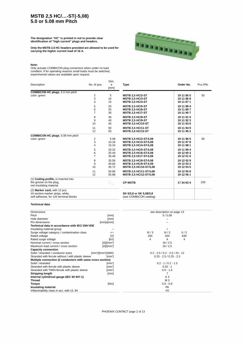
MSTB 2,5 HC/…-ST(-5,08)5.0 or 5.08 mm Pitch
PHOENIX CONTACT page 2 of 13
The designation "HC" is printed in red to provide clear identification of "high current" plugs and headers.
Only the MSTB 2,5 HC headers provided are allowed to be used for carrying the higher current load of 16 A.

Dim.Description No. of pos. a
[mm]
Type Order No.
Pcs./Pkt.
COMBICON HC plugs
, 5.0 mm pitch,with screw flange, color: green 2 5
3 10 4 15
5 20 6 25 7 30
8 359 40
10 45
11 5012 55
MSTB 2,5 HC/2-STFMSTB 2,5 HC/3-STFMSTB 2,5 HC/4-STF
MSTB 2,5 HC/5-STFMSTB 2,5 HC/6-STFMSTB 2,5 HC/7-STF
MSTB 2,5 HC/8-STFMSTB 2,5 HC/9-STFMSTB 2,5 HC/10-STF
MSTB 2,5 HC/11-STFMSTB 2,5 HC/12-STF
19 12 07 419 12 08 719 12 09 0
19 12 10 019 12 11 319 12 12 6
19 12 13 919 12 14 219 12 15 5
19 12 16 819 12 17 1
50
COMBICON HC plugs
, 5.08 mm pitch,with screw flange, color: green 2 5.08
3 10.16 4 15.24
5 20.32 6 25.40 7 30.48
8 35.569 40.64
10 45.72
11 50.8012 55.88
MSTB 2,5 HC/2-STF-5,08MSTB 2,5 HC/3-STF-5,08MSTB 2,5 HC/4-STF-5,08
MSTB 2,5 HC/5-STF-5,08MSTB 2,5 HC/6-STF-5,08MSTB 2,5 HC/7-STF-5,08
MSTB 2,5 HC/8-STF-5,08MSTB 2,5 HC/9-STF-5,08MSTB 2,5 HC/10-STF-5,08
MSTB 2,5 HC/11-STF-5,08MSTB 2,5 HC/12-STF-5,08
19 12 18 419 12 19 719 12 20 7
19 12 21 019 12 22 319 12 23 6
19 12 24 919 12 25 219 12 26 5
19 12 27 819 12 28 1
50
(1)
Coding profile,
is inserted into the groove on the plug,red insulating material
CP-MSTB 17 34 63 4
100
(2)
Marker card,
with 12 pcs. 10-section marker strips, white, self-adhesive, for 120 terminal blocks
SK 5/3,8 or SK 5,08/3,8
(see COMBICON catalog)
Technical data
Dimensions see description on page 13Pitch [mm] 5 / 5.08Hole diameter [mm| –Pin dimensions [mm]x[mm] –
Technical data in accordance with IEC/ DIN VDE
Insulating material group – ISurge voltage category / contamination class –/– III / 3 III / 2 II / 2Rated voltage [V] 250 320 630Rated surge voltage [kV] 4 4 4Nominal current / cross section [A]/[mm
2
] 16 / 2.5Maximum load current / cross section [A]/[mm
2
] 16 / 2.5
Capacity connection
Solid / stranded / conductor sizes [mm
2
]/[mm
2
]/AWG 0.2 - 2.5 / 0.2 - 2.5 / 24 - 12Stranded with ferrule without / with plastic sleeve [mm
2
] 0.25 - 2.5 / 0.25 - 2.5
Multiple connection (2 conductors with same cross section)
Solid / stranded [mm
2
] 0.2 - 1 / 0.2 - 1.5Stranded with ferrule with plastic sleeve [mm
2
] 0.25 - 1Stranded with TWIN ferrule with plastic sleeve [mm
2
] 0.5 - 1.5
Stripping length
[mm] 7
Internal cylindrical gauge (IEC 60 947-1)
A 3
Thread
M 3
Torque
[Nm] 0.5 - 0.6
Insulating material
PAInflammability class in acc. with UL 94 V0
MSTB 2,5 HC/…-STF(-5,08) with Srew Flange5.0 or 5.08 mm Pitch
Note:
Only actuate COMBICON plug connectors when under no load condition. If for operating reasons small loads must be switched, experimental values are available upon request.
PHOENIX CONTACT page 3 of 13
The designation "HC" is printed in red to provide clear identification of "high current" plugs and headers.
Only the MSTB 2,5 HC headers provided are allowed to be used for carrying the higher current load of 16 A.
Dim.Description No. of pos. a
[mm]
Type Order No.
Pcs./Pkt.
COMBICON HC plugs
, 5.0 mm pitch,color: green 2 5
3 10 4 15
5 20 6 25 7 30
8 359 40
10 45
11 5012 55
MSTBT 2,5 HC/2-STMSTBT 2,5 HC/3-STMSTBT 2,5 HC/4-ST
MSTBT 2,5 HC/5-STMSTBT 2,5 HC/6-STMSTBT 2,5 HC/7-ST
MSTBT 2,5 HC/8-STMSTBT 2,5 HC/9-STMSTBT 2,5 HC/10-ST
MSTBT 2,5 HC/11-STMSTBT 2,5 HC/12-ST
19 26 35 819 26 24 819 26 25 1
19 26 26 419 26 27 719 26 28 0
19 26 29 319 26 30 319 26 31 6
19 26 32 919 26 33 2
50
(1)
Coding profile,
is inserted into the groove on the plug,red insulating material
CP-MSTB 17 34 63 4
100
(2)
Marker card,
with 12 pcs. 10-section marker strips, white, self-adhesive, for 120 terminal blocks
SK 5/3,8
(see COMBICON catalog)
Technical data
Dimensions see description on page 13Pitch [mm] 5Hole diameter [mm| –Pin dimensions [mm]x[mm] –
Technical data in accordance with IEC/ DIN VDE
Insulating material group – ISurge voltage category / contamination class –/– III / 3 III / 2 II / 2Rated voltage [V] 250 320 630Rated surge voltage [kV] 4 4 4Nominal current / cross section [A]/[mm
2
] 16 / 2.5Maximum load current / cross section [A]/[mm
2
] 16 / 2.5
Capacity connection
Solid / stranded / conductor sizes [mm
2
]/[mm
2
]/AWG 0.2 - 2.5 / 0.2 - 2.5 / 24 - 12Stranded with ferrule without / with plastic sleeve [mm
2
] 0.25 - 2.5 / 0.25 - 2.5
Multiple connection (2 conductors with same cross section)
Solid / stranded [mm
2
] 0.2 - 1 / 0.2 - 1.5Stranded with ferrule with plastic sleeve [mm
2
] 0.25 - 1Stranded with TWIN ferrule with plastic sleeve [mm
2
] 0.5 - 1.5
Stripping length
[mm] 7
Internal cylindrical gauge (IEC 60 947-1)
A 3
Thread
M 3
Torque
[Nm] 0.5 - 0.6
Insulating material
PAInflammability class in acc. with UL 94 V0
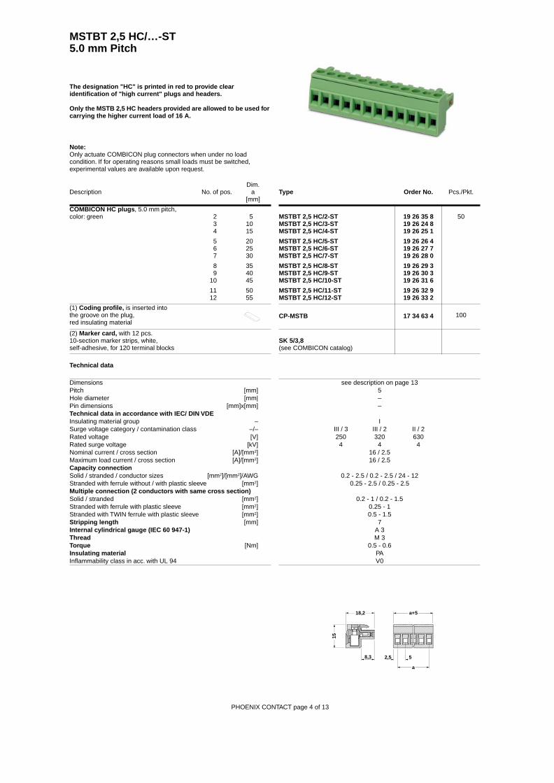
MSTBT 2,5 HC/…-ST 5.0 mm Pitch
Note:
Only actuate COMBICON plug connectors when under no load condition. If for operating reasons small loads must be switched, experimental values are available upon request.
PHOENIX CONTACT page 4 of 13
The designation "HC" is printed in red to provide clear identification of "high current" plugs and headers.
Only the MSTB 2,5 HC headers provided are allowed to be used for carrying the higher current load of 16 A.
2,5 5
a+5
a
18,2
15
8,3

Dim.Description No. of pos. a
[mm]
Type Order No.
Pcs./Pkt.
COMBICON HC plugs
, 5.0 mm pitch,plug-in direction vertical to the conductor axis, 2 5connection point facing the smooth wall (R) 3 10of the header, color: green 4 15
5 20 6 25 7 30
8 359 40
10 45
11 5012 55
MVSTBR 2,5 HC/2-STMVSTBR 2,5 HC/3-STMVSTBR 2,5 HC/4-ST
MVSTBR 2,5 HC/5-STMVSTBR 2,5 HC/6-STMVSTBR 2,5 HC/7-ST
MVSTBR 2,5 HC/8-STMVSTBR 2,5 HC/9-STMVSTBR 2,5 HC/10-ST
MVSTBR 2,5 HC/11-STMVSTBR 2,5 HC/12-ST
19 12 29 419 12 30 419 12 31 7
19 12 32 019 12 33 319 12 34 6
19 12 35 919 12 36 219 12 37 5
19 12 38 819 12 39 1
50
COMBICON HC plugs
, 5.08 mm pitch,plug-in direction vertical to the conductor axis, 2 5.08connection point facing the smooth wall (R) 3 10.16of the header, color: green 4 15.24
5 20.32 6 25.40 7 30.48
8 35.569 40.64
10 45.72
11 50.8012 55.88
MVSTBR 2,5 HC/2-ST-5,08MVSTBR 2,5 HC/3-ST-5,08MVSTBR 2,5 HC/4-ST-5,08
MVSTBR 2,5 HC/5-ST-5,08MVSTBR 2,5 HC/6-ST-5,08MVSTBR 2,5 HC/7-ST-5,08
MVSTBR 2,5 HC/8-ST-5,08MVSTBR 2,5 HC/9-ST-5,08MVSTBR 2,5 HC/10-ST-5,08
MVSTBR 2,5 HC/11-ST-5,08MVSTBR 2,5 HC/12-ST-5,08
19 12 40 119 12 41 419 12 42 7
19 12 43 019 12 44 319 12 45 6
19 12 46 919 12 47 219 12 48 5
19 12 49 819 12 50 8
50
(1)
Coding profile,
is inserted into the groove on the plug,red insulating material
CP-MSTB 17 34 63 4
100
(2)
Marker card,
with 12 pcs. 10-section marker strips, white, self-adhesive, for 120 terminal blocks
SK 5/3,8 or SK 5,08/3,8
(see COMBICON catalog)
Technical data
Dimensions see description on page 13Pitch [mm] 5 / 5.08Hole diameter [mm| –Pin dimensions [mm]x[mm] –
Technical data in accordance with IEC/ DIN VDE
Insulating material group – ISurge voltage category / contamination class –/– III / 3 III / 2 II / 2Rated voltage [V] 250 320 630Rated surge voltage [kV] 4 4 4Nominal current / cross section [A]/[mm
2
] 16 / 2.5Maximum load current / cross section [A]/[mm
2
] 16 / 2.5
Capacity connection
Solid / stranded / conductor sizes [mm
2
]/[mm
2
]/AWG 0.2 - 2.5 / 0.2 - 2.5 / 24 - 12Stranded with ferrule without / with plastic sleeve [mm
2
] 0.25 - 2.5 / 0.25 - 2.5
Multiple connection (2 conductors with same cross section)
Solid / stranded [mm
2
] 0.2 - 1 / 0.2 - 1.5Stranded with ferrule with plastic sleeve [mm
2
] 0.25 - 1Stranded with TWIN ferrule with plastic sleeve [mm
2
] 0.5 - 1.5
Stripping length
[mm] 7
Internal cylindrical gauge (IEC 60 947-1)
A 3
Thread
M 3
Torque
[Nm] 0.5 - 0.6
Insulating material
PAInflammability class in acc. with UL 94 V0
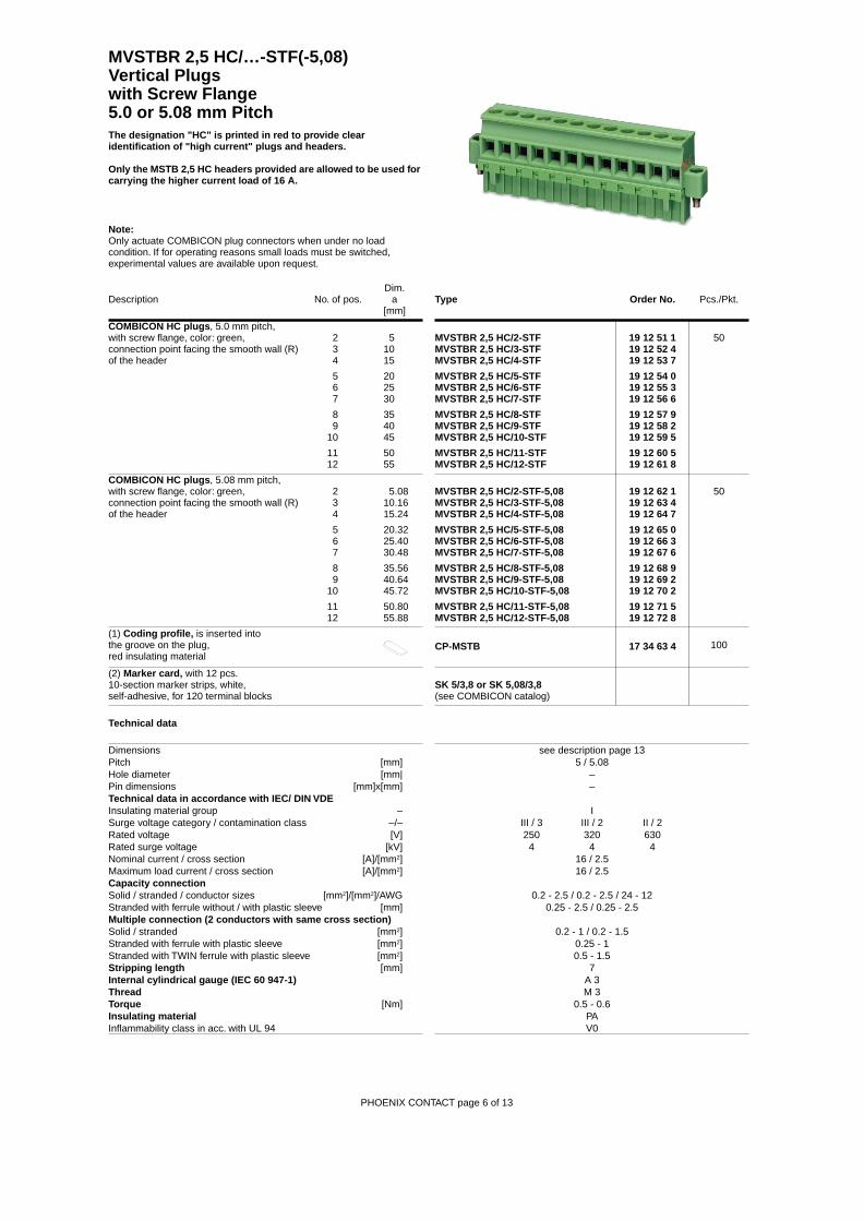
MVSTBR 2,5 HC/…-ST(-5,08) Vertical Plugs5.0 or 5.08 mm Pitch
Note:
Only actuate COMBICON plug connectors when under no load condition. If for operating reasons small loads must be switched, experimental values are available upon request.
PHOENIX CONTACT page 5 of 13
The designation "HC" is printed in red to provide clear identification of "high current" plugs and headers.
Only the MSTB 2,5 HC headers provided are allowed to be used for carrying the higher current load of 16 A.
Dim.Description No. of pos. a
[mm]
Type Order No.
Pcs./Pkt.
COMBICON HC plugs
, 5.0 mm pitch,with screw flange, color: green, 2 5connection point facing the smooth wall (R) 3 10of the header 4 15
5 20 6 25 7 30
8 359 40
10 45
11 5012 55
MVSTBR 2,5 HC/2-STFMVSTBR 2,5 HC/3-STFMVSTBR 2,5 HC/4-STF
MVSTBR 2,5 HC/5-STFMVSTBR 2,5 HC/6-STFMVSTBR 2,5 HC/7-STF
MVSTBR 2,5 HC/8-STFMVSTBR 2,5 HC/9-STFMVSTBR 2,5 HC/10-STF
MVSTBR 2,5 HC/11-STFMVSTBR 2,5 HC/12-STF
19 12 51 119 12 52 419 12 53 7
19 12 54 019 12 55 319 12 56 6
19 12 57 919 12 58 219 12 59 5
19 12 60 519 12 61 8
50
COMBICON HC plugs
, 5.08 mm pitch,with screw flange, color: green, 2 5.08connection point facing the smooth wall (R) 3 10.16of the header 4 15.24
5 20.32 6 25.40 7 30.48
8 35.569 40.64
10 45.72
11 50.8012 55.88
MVSTBR 2,5 HC/2-STF-5,08MVSTBR 2,5 HC/3-STF-5,08MVSTBR 2,5 HC/4-STF-5,08
MVSTBR 2,5 HC/5-STF-5,08MVSTBR 2,5 HC/6-STF-5,08MVSTBR 2,5 HC/7-STF-5,08
MVSTBR 2,5 HC/8-STF-5,08MVSTBR 2,5 HC/9-STF-5,08MVSTBR 2,5 HC/10-STF-5,08
MVSTBR 2,5 HC/11-STF-5,08MVSTBR 2,5 HC/12-STF-5,08
19 12 62 119 12 63 419 12 64 7
19 12 65 019 12 66 319 12 67 6
19 12 68 919 12 69 219 12 70 2
19 12 71 519 12 72 8
50
(1)
Coding profile,
is inserted intothe groove on the plug,red insulating material
CP-MSTB 17 34 63 4
100
(2)
Marker card,
with 12 pcs. 10-section marker strips, white, self-adhesive, for 120 terminal blocks
SK 5/3,8 or SK 5,08/3,8
(see COMBICON catalog)
Technical data
Dimensions see description page 13Pitch [mm] 5 / 5.08Hole diameter [mm| –Pin dimensions [mm]x[mm] –
Technical data in accordance with IEC/ DIN VDE
Insulating material group – ISurge voltage category / contamination class –/– III / 3 III / 2 II / 2Rated voltage [V] 250 320 630Rated surge voltage [kV] 4 4 4Nominal current / cross section [A]/[mm
2
] 16 / 2.5Maximum load current / cross section [A]/[mm
2
] 16 / 2.5
Capacity connection
Solid / stranded / conductor sizes [mm
2
]/[mm
2
]/AWG 0.2 - 2.5 / 0.2 - 2.5 / 24 - 12Stranded with ferrule without / with plastic sleeve [mm] 0.25 - 2.5 / 0.25 - 2.5
Multiple connection (2 conductors with same cross section)
Solid / stranded [mm
2
] 0.2 - 1 / 0.2 - 1.5Stranded with ferrule with plastic sleeve [mm
2
] 0.25 - 1Stranded with TWIN ferrule with plastic sleeve [mm
2
] 0.5 - 1.5
Stripping length
[mm] 7
Internal cylindrical gauge (IEC 60 947-1)
A 3
Thread
M 3
Torque
[Nm] 0.5 - 0.6
Insulating material
PAInflammability class in acc. with UL 94 V0
MVSTBR 2,5 HC/…-STF(-5,08) Vertical Plugs with Screw Flange5.0 or 5.08 mm Pitch
Note:
Only actuate COMBICON plug connectors when under no load condition. If for operating reasons small loads must be switched, experimental values are available upon request.
PHOENIX CONTACT page 6 of 13
The designation "HC" is printed in red to provide clear identification of "high current" plugs and headers.
Only the MSTB 2,5 HC headers provided are allowed to be used for carrying the higher current load of 16 A.

Dim.Description No. of pos. a
[mm]
Type Order No.
Pcs./Pkt.
COMBICON HC plugs
, 5.0 mm pitch,plug-in direction vertical to the conductor axis, 2 5connection point facing the rippled wall (W) 3 10of the header, color: green 4 15
5 20 6 25 7 30
8 359 40
10 45
11 5012 55
MVSTBW 2,5 HC/2-STMVSTBW 2,5 HC/3-STMVSTBW 2,5 HC/4-ST
MVSTBW 2,5 HC/5-STMVSTBW 2,5 HC/6-STMVSTBW 2,5 HC/7-ST
MVSTBW 2,5 HC/8-STMVSTBW 2,5 HC/9-STMVSTBW 2,5 HC/10-ST
MVSTBW 2,5 HC/11-STMVSTBW 2,5 HC/12-ST
19 12 73 119 12 74 419 12 75 7
19 12 76 019 12 77 319 12 78 6
19 12 79 919 12 80 919 12 81 2
19 12 82 519 12 83 8
50
COMBICON HC plugs
, 5.08 mm pitch,plug-in direction vertical to the conductor axis, 2 5.08connection point facing the rippled wall (W) 3 10.16of the header, color: green 4 15.24
5 20.32 6 25.40 7 30.48
8 35.569 40.64
10 45.72
11 50.8012 55.88
MVSTBW 2,5 HC/2-ST-5,08MVSTBW 2,5 HC/3-ST-5,08MVSTBW 2,5 HC/4-ST-5,08
MVSTBW 2,5 HC/5-ST-5,08MVSTBW 2,5 HC/6-ST-5,08MVSTBW 2,5 HC/7-ST-5,08
MVSTBW 2,5 HC/8-ST-5,08MVSTBW 2,5 HC/9-ST-5,08MVSTBW 2,5 HC/10-ST-5,08
MVSTBW 2,5 HC/11-ST-5,08MVSTBW 2,5 HC/12-ST-5,08
19 12 84 119 12 85 419 12 86 7
19 12 87 019 12 88 319 12 89 6
19 12 90 619 12 91 919 12 92 2
19 12 93 519 12 94 8
50
(1)
Coding profile,
is inserted into the groove on the plug,red insulating material
CP-MSTB 17 34 63 4
100
(2)
Marker card,
with 12 pcs. 10-section marker strips, white, self-adhesive, for 120 terminal blocks
SK 5/3,8 or SK 5,08/3,8
(see COMBICON catalog)
Technical data
Dimensions see description on page 13Pitch [mm] 5 / 5.08Hole diameter [mm| –Pin dimensions [mm]x[mm] –
Technical data in accordance with IEC/ DIN VDEInsulating material group – ISurge voltage category / contamination class –/– III / 3 III / 2 II / 2Rated voltage [V] 250 320 630Rated surge voltage [kV] 4 4 4Nominal current / cross section [A]/[mm2] 16 / 2.5Maximum load current / cross section [A]/[mm2] 16 / 2.5Capacity connectionSolid / stranded / conductor sizes [mm2]/[mm2]/AWG 0.2 - 2.5 / 0.2 - 2.5 / 24 - 12Stranded with ferrule without / with plastic sleeve [mm2] 0.25 - 2.5 / 0.25 - 2.5Multiple connection (2 conductors with same cross section)Solid / stranded [mm2] 0.2 - 1 / 0.2 - 1.5Stranded with ferrule with plastic sleeve [mm2] 0.25 - 1Stranded with TWIN ferrule with plastic sleeve [mm2] 0.5 - 1.5Stripping length [mm] 7Internal cylindrical gauge (IEC 60 947-1) A 3Thread M 3Torque [Nm] 0.5 - 0.6Insulating material PAInflammability class in acc. with UL 94 V0
MVSTBW 2,5 HC/…-ST(-5,08) Vertical Plugs5.0 or 5.08 mm Pitch
Note:Only actuate COMBICON plug connectors when under no load condition. If for operating reasons small loads must be switched, experimental values are available upon request.
PHOENIX CONTACT page 7 of 13
The designation "HC" is printed in red to provide clear identification of "high current" plugs and headers.
Only the MSTB 2,5 HC headers provided are allowed to be used for carrying the higher current load of 16 A.

Dim.Description No. of pos. a
[mm]Type Order No. Pcs./Pkt.
COMBICON HC plugs , 5.0 mm pitch,with screw flange, color: green, 2 5connection point facing the rippled wall (W) 3 10of the header 4 15
5 20 6 25 7 30
8 359 40
10 45
11 5012 55
MVSTBW 2,5 HC/2-STFMVSTBW 2,5 HC/3-STFMVSTBW 2,5 HC/4-STF
MVSTBW 2,5 HC/5-STFMVSTBW 2,5 HC/6-STFMVSTBW 2,5 HC/7-STF
MVSTBW 2,5 HC/8-STFMVSTBW 2,5 HC/9-STFMVSTBW 2,5 HC/10-STF
MVSTBW 2,5 HC/11-STFMVSTBW 2,5 HC/12-STF
19 12 95 119 12 96 419 12 97 7
19 12 98 019 12 99 319 13 00 2
19 13 01 519 13 02 819 13 03 1
19 13 04 419 13 05 7
50
COMBICON HC plugs , 5.08 mm pitch,with screw flange, color: green, 2 5.08connection point facing the rippled wall (W) 3 10.16of the header 4 15.24
5 20.32 6 25.40 7 30.48
8 35.569 40.64
10 45.72
11 50.8012 55.88
MVSTBW 2,5 HC/2-STF-5,08MVSTBW 2,5 HC/3-STF-5,08MVSTBW 2,5 HC/4-STF-5,08
MVSTBW 2,5 HC/5-STF-5,08MVSTBW 2,5 HC/6-STF-5,08MVSTBW 2,5 HC/7-STF-5,08
MVSTBW 2,5 HC/8-STF-5,08MVSTBW 2,5 HC/9-STF-5,08MVSTBW 2,5 HC/10-STF-5,08
MVSTBW 2,5 HC/11-STF-5,08MVSTBW 2,5 HC/12-STF-5,08
19 13 06 019 13 07 319 13 08 6
19 13 09 919 13 10 919 13 11 2
19 13 12 519 13 13 819 13 14 1
19 13 15 419 13 16 7
50
(1) Coding profile, is inserted into the groove on the plug,red insulating material
CP-MSTB 17 34 63 4 100
(2) Marker card, with 12 pcs. 10-section marker strips, white, self-adhesive, for 120 terminal blocks
SK 5/3,8 or SK 5,08/3,8 (see COMBICON catalog)
Technical data
Dimensions see description on page 13Pitch [mm] 5 / 5.08Hole diameter [mm| –Pin dimensions [mm]x[mm] –Technical data in accordance with IEC/ DIN VDEInsulating material group – ISurge voltage category / contamination class –/– III / 3 III / 2 II / 2Rated voltage [V] 250 320 630Rated surge voltage [kV] 4 4 4Nominal current / cross section [A]/[mm2] 16 / 2.5Maximum load current / cross section [A]/[mm2] 16 / 2.5Capacity connectionSolid / stranded / conductor sizes [mm2]/[mm2]/AWG 0.2 - 2.5 / 0.2 - 2.5 / 24 - 12Stranded with ferrule without / with plastic sleeve [mm2] 0.25 - 2.5 / 0.25 - 2.5Multiple connection (2 conductors with same cross section)Solid / stranded [mm2] 0.2 - 1 / 0.2 - 1.5Stranded with ferrule with plastic sleeve [mm2] 0.25 - 1Stranded with TWIN ferrule with plastic sleeve [mm2] 0.5 - 1.5Stripping length [mm] 7Internal cylindrical gauge (IEC 60 947-1) A 3Thread M 3Torque [Nm] 0.5 - 0.6Insulating material PAInflammability class in acc. with UL 94 V0
MVSTBW 2,5 HC/…-STF(-5,08) Vertical Plugs with Screw Flange5.0 or 5.08 mm Pitch
Note:Only actuate COMBICON plug connectors when under no load condition. If for operating reasons small loads must be switched, experimental values are available upon request.
PHOENIX CONTACT page 8 of 13
The designation "HC" is printed in red to provide clear identification of "high current" plugs and headers.
Only the MSTB 2,5 HC headers provided are allowed to be used for carrying the higher current load of 16 A.

Dim.Description No. of pos. a
[mm]Type Order No. Pcs./Pkt.
COMBICON HC headers , 5.0 mm pitch,plug-in direction parallel to the p.c.b., 2 5color: green 3 10
4 15
5 20 6 25 7 30
8 359 40
10 45
11 5012 55
MSTBA 2,5 HC/2-GMSTBA 2,5 HC/3-GMSTBA 2,5 HC/4-G
MSTBA 2,5 HC/5-GMSTBA 2,5 HC/6-GMSTBA 2,5 HC/7-G
MSTBA 2,5 HC/8-GMSTBA 2,5 HC/9-GMSTBA 2,5 HC/10-G
MSTBA 2,5 HC/11-GMSTBA 2,5 HC/12-G
19 23 75 919 23 76 219 23 77 5
19 23 78 819 23 79 119 23 80 1
19 23 81 419 23 82 719 23 83 0
19 23 84 319 23 85 6
50
COMBICON HC headers , 5.08 mm pitch,plug-in direction parallel to the p.c.b., 2 5.08color: green 3 10.16
4 15.24
5 20.32 6 25.40 7 30.48
8 35.569 40.64
10 45.72
11 50.8012 55.88
MSTBA 2,5 HC/2-G-5,08MSTBA 2,5 HC/3-G-5,08MSTBA 2,5 HC/4-G-5,08
MSTBA 2,5 HC/5-G-5,08MSTBA 2,5 HC/6-G-5,08MSTBA 2,5 HC/7-G-5,08
MSTBA 2,5 HC/8-G-5,08MSTBA 2,5 HC/9-G-5,08MSTBA 2,5 HC/10-G-5,08
MSTBA 2,5 HC/11-G-5,08MSTBA 2,5 HC/12-G-5,08
19 23 86 919 23 87 219 23 88 5
19 23 89 819 23 90 819 23 91 1
19 23 92 419 23 93 719 23 94 0
19 12 95 319 12 96 6
50
(1) Coding section, inserted into the recess in the header,red insulating material
CR-MSTB 17 34 40 1 100
(2) Marker card, with 12 pcs. 10-section marker strips, white, self-adhesive, for 120 terminal blocks
SK 5/3,8 or SK 5,08/3,8 (see COMBICON catalog)
Technical data
Dimensions see descriptionPitch [mm] 5 / 5.08Hole diameter [mm| 1.4Pin dimensions [mm]x[mm] 1 x 1Technical data in accordance with IEC/ DIN VDEInsulating material group – IIIaSurge voltage category / contamination class –/– III / 3 III / 2 II / 2Rated voltage [V] 250 320 400Rated surge voltage [kV] 4 4 4Nominal current / cross section [A]/[mm2] 16 / –Maximum load current / cross section [A]/[mm2] 16 / –Insulating material PBTInflammability class in acc. with UL 94 V0
MSTBA 2,5 HC/…-G(-5,08) 5.0 or 5.08 mm Pitch
Note:Only actuate COMBICON plug connectors when under no load condition. If for operating reasons small loads must be switched, experimental values are available upon request.
PHOENIX CONTACT page 9 of 13
The designation "HC" is printed in red to provide clear identification of "high current" plugs and headers.
Only the MSTB 2,5 HC headers provided are allowed to be used for carrying the higher current load of 16 A.
8,6
12
22
153,
5 2
(a+7,08)
a
3,5 5(5,08)(3,54)
a+7a
5
2
(5,08)
1,4
3,5(3,54)

Dim.Description No. of pos. a
[mm]Type Order No. Pcs./Pkt.
COMBICON HC headers vertical ,5.0 mm pitch, color: green, 2 5plug-in direction vertical to the p.c.b. 3 10
4 15
5 20 6 25 7 30
8 359 40
10 45
11 5012 55
MSTBVA 2,5 HC/2-GMSTBVA 2,5 HC/3-GMSTBVA 2,5 HC/4-G
MSTBVA 2,5 HC/5-GMSTBVA 2,5 HC/6-GMSTBVA 2,5 HC/7-G
MSTBVA 2,5 HC/8-GMSTBVA 2,5 HC/9-GMSTBVA 2,5 HC/10-G
MSTBVA 2,5 HC/11-GMSTBVA 2,5 HC/12-G
19 24 19 819 24 20 819 24 21 1
19 24 22 419 24 23 719 24 24 0
19 24 25 319 24 26 619 24 27 9
19 24 28 219 24 29 5
50
COMBICON HC headers vertical , 5.08 mm pitch, color: green, 2 5.08plug-in direction vertical to the p.c.b. 3 10.16
4 15.24
5 20.32 6 25.40 7 30.48
8 35.569 40.64
10 45.72
11 50.8012 55.88
MSTBVA 2,5 HC/2-G-5,08MSTBVA 2,5 HC/3-G-5,08MSTBVA 2,5 HC/4-G-5,08
MSTBVA 2,5 HC/5-G-5,08MSTBVA 2,5 HC/6-G-5,08MSTBVA 2,5 HC/7-G-5,08
MSTBVA 2,5 HC/8-G-5,08MSTBVA 2,5 HC/9-G-5,08MSTBVA 2,5 HC/10-G-5,08
MSTBVA 2,5 HC/11-G-5,08MSTBVA 2,5 HC/12-G-5,08
19 24 30 519 24 31 819 24 32 1
19 24 33 419 24 34 719 24 35 0
19 24 36 319 24 37 619 24 38 9
19 24 39 219 24 40 2
50
(1) Coding section, inserted into the recess in the header,red insulating material
CR-MSTB 17 34 40 1 100
(2) Marker card, with 12 pcs. 10-section marker strips, white, self-adhesive, for 120 terminal blocks
SK 5/3,8 or SK 5,08/3,8 (see COMBICON catalog)
Technical data
Dimensions see descriptionPitch [mm] 5 / 5.08Hole diameter [mm| 1.4Pin dimensions [mm]x[mm] 1 x 1Technical data in accordance with IEC/ DIN VDEInsulating material group – ISurge voltage category / contamination class –/– III / 3 III / 2 II / 2Rated voltage [V] 250 320 400Rated surge voltage [kV] 4 4 4Nominal current / cross section [A]/[mm2] 16 / –Maximum load current / cross section [A]/[mm2] 16 / –Insulating material PAInflammability class in acc. with UL 94 V0
MSTBVA 2,5 HC/…-G(-5,08) 5.0 or 5.08 mm Pitch
Note:Only actuate COMBICON plug connectors when under no load condition. If for operating reasons small loads must be switched, experimental values are available upon request.
PHOENIX CONTACT page 10 of 13
The designation "HC" is printed in red to provide clear identification of "high current" plugs and headers.
Only the MSTB 2,5 HC headers provided are allowed to be used for carrying the higher current load of 16 A.
a5
(5,08)
3,8
1,4
3,5(3,54)
12,6
15
22
29,5
3,9
12
a+7(a+7,08)
3,8
8,6
3,5 5
a(3,54) (5,08)
Dim.Description No. of pos. a
[mm]Type Order No. Pcs./Pkt.
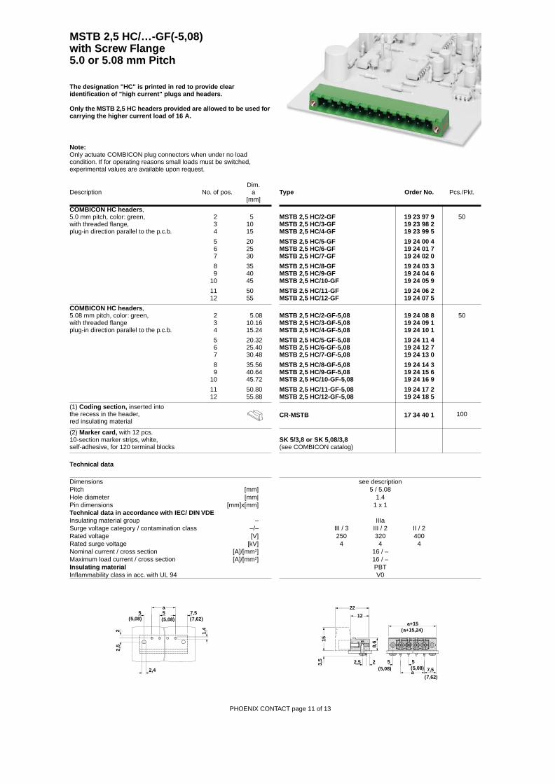
COMBICON HC headers ,5.0 mm pitch, color: green, 2 5with threaded flange, 3 10plug-in direction parallel to the p.c.b. 4 15
5 20 6 25 7 30
8 359 40
10 45
11 5012 55
MSTB 2,5 HC/2-GFMSTB 2,5 HC/3-GFMSTB 2,5 HC/4-GF
MSTB 2,5 HC/5-GFMSTB 2,5 HC/6-GFMSTB 2,5 HC/7-GF
MSTB 2,5 HC/8-GFMSTB 2,5 HC/9-GFMSTB 2,5 HC/10-GF
MSTB 2,5 HC/11-GFMSTB 2,5 HC/12-GF
19 23 97 919 23 98 219 23 99 5
19 24 00 419 24 01 719 24 02 0
19 24 03 319 24 04 619 24 05 9
19 24 06 219 24 07 5
50
COMBICON HC headers , 5.08 mm pitch, color: green, 2 5.08with threaded flange 3 10.16plug-in direction parallel to the p.c.b. 4 15.24
5 20.32 6 25.40 7 30.48
8 35.569 40.64
10 45.72
11 50.8012 55.88
MSTB 2,5 HC/2-GF-5,08MSTB 2,5 HC/3-GF-5,08MSTB 2,5 HC/4-GF-5,08
MSTB 2,5 HC/5-GF-5,08MSTB 2,5 HC/6-GF-5,08MSTB 2,5 HC/7-GF-5,08
MSTB 2,5 HC/8-GF-5,08MSTB 2,5 HC/9-GF-5,08MSTB 2,5 HC/10-GF-5,08
MSTB 2,5 HC/11-GF-5,08MSTB 2,5 HC/12-GF-5,08
19 24 08 819 24 09 119 24 10 1
19 24 11 419 24 12 719 24 13 0
19 24 14 319 24 15 619 24 16 9
19 24 17 219 24 18 5
50
(1) Coding section, inserted into the recess in the header,red insulating material
CR-MSTB 17 34 40 1 100
(2) Marker card, with 12 pcs. 10-section marker strips, white, self-adhesive, for 120 terminal blocks
SK 5/3,8 or SK 5,08/3,8 (see COMBICON catalog)
Technical data
Dimensions see descriptionPitch [mm] 5 / 5.08Hole diameter [mm| 1.4Pin dimensions [mm]x[mm] 1 x 1Technical data in accordance with IEC/ DIN VDEInsulating material group – IIIaSurge voltage category / contamination class –/– III / 3 III / 2 II / 2Rated voltage [V] 250 320 400Rated surge voltage [kV] 4 4 4Nominal current / cross section [A]/[mm2] 16 / –Maximum load current / cross section [A]/[mm2] 16 / –Insulating material PBTInflammability class in acc. with UL 94 V0
MSTB 2,5 HC/…-GF(-5,08) with Screw Flange5.0 or 5.08 mm Pitch
Note:Only actuate COMBICON plug connectors when under no load condition. If for operating reasons small loads must be switched, experimental values are available upon request.
PHOENIX CONTACT page 11 of 13
The designation "HC" is printed in red to provide clear identification of "high current" plugs and headers.
Only the MSTB 2,5 HC headers provided are allowed to be used for carrying the higher current load of 16 A.
2,5
2 1,4
a5 5 7,5
(7,62)(5,08)(5,08)
2,4
a+15(a+15,24)
5 5
7,5(5,08) (5,08)
(7,62)a
8,6
12
22
153,
5 22,5
Dim.Description No. of pos. a
[mm]Type Order No. Pcs./Pkt.
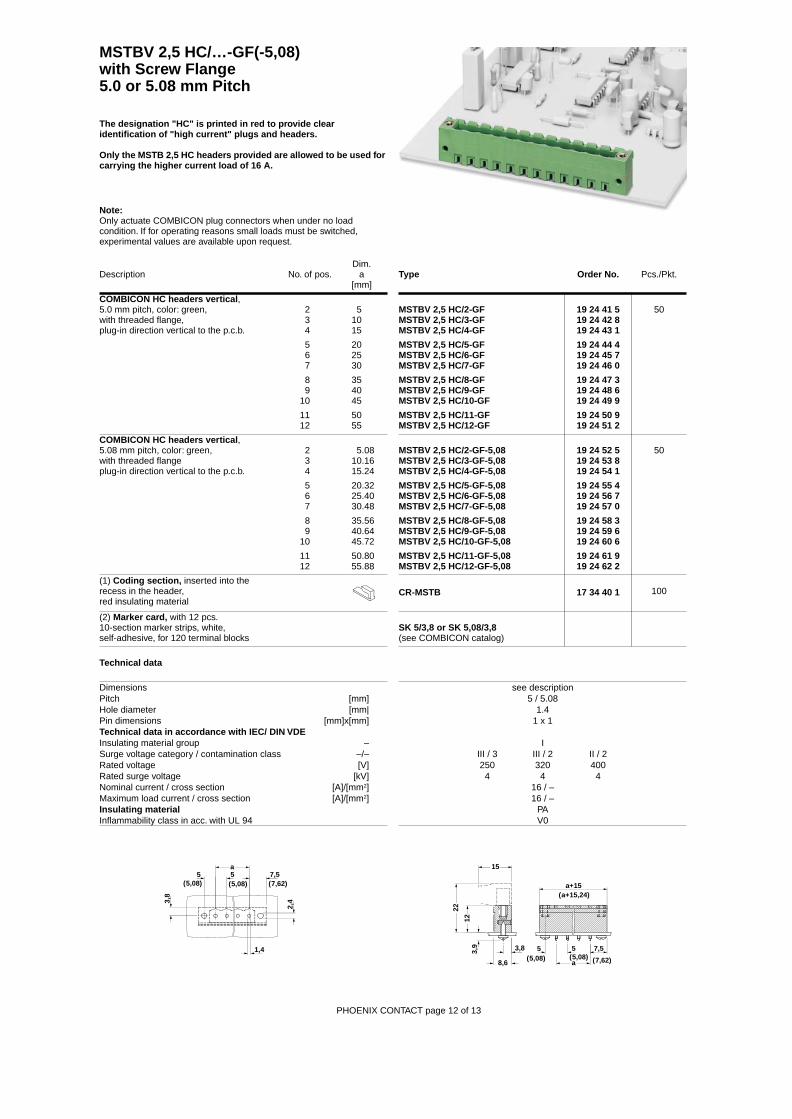
COMBICON HC headers vertical ,5.0 mm pitch, color: green, 2 5with threaded flange, 3 10plug-in direction vertical to the p.c.b. 4 15
5 20 6 25 7 30
8 359 40
10 45
11 5012 55
MSTBV 2,5 HC/2-GFMSTBV 2,5 HC/3-GFMSTBV 2,5 HC/4-GF
MSTBV 2,5 HC/5-GFMSTBV 2,5 HC/6-GFMSTBV 2,5 HC/7-GF
MSTBV 2,5 HC/8-GFMSTBV 2,5 HC/9-GFMSTBV 2,5 HC/10-GF
MSTBV 2,5 HC/11-GFMSTBV 2,5 HC/12-GF
19 24 41 519 24 42 819 24 43 1
19 24 44 419 24 45 719 24 46 0
19 24 47 319 24 48 619 24 49 9
19 24 50 919 24 51 2
50
COMBICON HC headers vertical , 5.08 mm pitch, color: green, 2 5.08with threaded flange 3 10.16plug-in direction vertical to the p.c.b. 4 15.24
5 20.32 6 25.40 7 30.48
8 35.569 40.64
10 45.72
11 50.8012 55.88
MSTBV 2,5 HC/2-GF-5,08MSTBV 2,5 HC/3-GF-5,08MSTBV 2,5 HC/4-GF-5,08
MSTBV 2,5 HC/5-GF-5,08MSTBV 2,5 HC/6-GF-5,08MSTBV 2,5 HC/7-GF-5,08
MSTBV 2,5 HC/8-GF-5,08MSTBV 2,5 HC/9-GF-5,08MSTBV 2,5 HC/10-GF-5,08
MSTBV 2,5 HC/11-GF-5,08MSTBV 2,5 HC/12-GF-5,08
19 24 52 519 24 53 819 24 54 1
19 24 55 419 24 56 719 24 57 0
19 24 58 319 24 59 619 24 60 6
19 24 61 919 24 62 2
50
(1) Coding section, inserted into therecess in the header,red insulating material
CR-MSTB 17 34 40 1 100
(2) Marker card, with 12 pcs. 10-section marker strips, white, self-adhesive, for 120 terminal blocks
SK 5/3,8 or SK 5,08/3,8 (see COMBICON catalog)
Technical data
Dimensions see descriptionPitch [mm] 5 / 5.08Hole diameter [mm| 1.4Pin dimensions [mm]x[mm] 1 x 1Technical data in accordance with IEC/ DIN VDEInsulating material group – ISurge voltage category / contamination class –/– III / 3 III / 2 II / 2Rated voltage [V] 250 320 400Rated surge voltage [kV] 4 4 4Nominal current / cross section [A]/[mm2] 16 / –Maximum load current / cross section [A]/[mm2] 16 / –Insulating material PAInflammability class in acc. with UL 94 V0
MSTBV 2,5 HC/…-GF(-5,08) with Screw Flange5.0 or 5.08 mm Pitch
Note:Only actuate COMBICON plug connectors when under no load condition. If for operating reasons small loads must be switched, experimental values are available upon request.
PHOENIX CONTACT page 12 of 13
The designation "HC" is printed in red to provide clear identification of "high current" plugs and headers.
Only the MSTB 2,5 HC headers provided are allowed to be used for carrying the higher current load of 16 A.
3,9
12
22
15
3,8
8,6
a+15
5 5(5,08) (5,08)
7,5
(7,62)a
(a+15,24)
5(5,08)
3,8
(7,62)7,55
(5,08)
a
2,4
1,4

Descriptions
PHOENIX CONTACT page 13 of 13
P
HO
EN
IX C
ON
TAC
T 1
5.03
.01
TN
R: 5
0995
53-0
1 ht
tp://
ww
w.p
hoen
ixco
ntac
t.com
MSTB 2,5 HC/…-ST(-5,08) MSTB 2,5 HC/…-STF(-5,08)
MVSTBR 2,5 HC/…-ST(-5.08) MVSTBR 2,5 HC/…-STF(-5,08)
MVSTBW 2,5 HC/…-STF(-5,08) MVSTBW 2,5 HC/…-STF(-5,08)
15
18,2
8,3 2,5 5
(a+5,08)
(5,08)(2,54)
a+5
a
15
18,2
8,3
a
a+5
5
(a+5,08)
(5,08)5
(5,08)
4,9
8,3
26
12,6 a+5(a+5,08)
2,5 5(2,54) (5,08)
a
8,3
26
12,6(a+6,08)
5(5,08)
5(5,08)a
a+64,5(4,58)
8,3
26
12,6
2,5 5
a+5(a+5,08)
(2,54) (5,08)a
8,3
26
12,6
5
(a+6,08)
(5,08)a
a+6
5(5,08)
4,5(4,58)