Embed Size (px)
Citation preview

13
ATEX type examination certificate:
Marking acc. to 2014/34/EU and standard:
EN 60079-0
IECEx type examination certificate:
Category of application: IEC60079-0
(A)The EC-Type Examination Certificate and any future supplements thereto shall, at the same time, be regarded as supplements to
the EC-Type Examination Certificates PTB 99 ATEX 3128 X and PTB 99 ATEX 3101 X
Perm. storage temperature in original packing: to
Degree of protection to IEC/EN 60529: (when fully assembled)
1 Technical data
1.1 Technical details for: Cable entries (KLE) M12x1,5 to M63x1,5
Type SW L1 L2 Eweight app.
Dimension drawings and dimensions in mm
Typeoperating tempera-ture
impact resistance Cable diameter
Screw-in thread in enclosure
Colour of dust protection cover
Seal 1+2+3 1 2 3 Seal 1+2 1 2 3 Seal 1 1 2 3
min. max. min. max. min. max.°C Joule Ø Nm** Ø(1)(2) Nm** Ø Nm** Ø(1)(2) Nm** Ø Nm** Ø(2) Nm** Nm**
whitewhitewhitegreenwhitegreenwhitegreengreen
green
green
additional seal
** Test torques at 20°C
(1) The tests of clamping ranges and torque values were performed with metal mandrel. The clamping range can vary by using cables with different manufacturing tolerances and material properties. Please use the combination of sealing 1 + 2 + 3 for the intermediate region.
(2) When selecting the seal rubber, ensure that the cap nut can be tightened when carrying out any future maintenance work on the cable entry.
1 2 3 1+2+31+211 2 3 1+2+31+211 2 3 1+2+31+21
Fig. D Cable diameter 16 mm e.g. for M25x1,5
Fig. C Cable diameter 12 mm e.g. for M25x1,5
seal 2seal 1
Ø 9 mmuse seal 1 + 2 + 3.
Fig. B Cable diameter 9 mm e.g. for M25x1,5
seal 3 seal 2seal 1 seal 3
Ø 12 mmUse seal 1 + 2. Remove seal 3.
Ø 16 mmUse seal 1. Remove seal 2 + 3.
seal 2seal 1 seal 3
GBCable entries, blanking plugs, screw plugs, trumpet-shaped cable glands, reducing glands and drain plugs
Pressure screwIntermediate gland
Fig. A
>5 mm
0 mm
M12, M16 (Ø < 9 mm), M20 ... M63
M16 (Ø > 9 mm)
Ø
Ø
PTB 14 ATEX 1015 X(A)
II 2 G Ex eb IIC Gb
II 2 D Ex tb IIIC Db IECEx PTB 14.0027X(A)
Ex eb IIC Gb
Ex tb IIIC Db
-20° C +70° C
IP 66
M12x1,5 15 mm 19,3 mm 12 / 8 mm 16,2 mm 3,4 gM16x1,5 20 mm 23,0 mm 12 / 8 mm 22,0 mm 6,5 gM20x1,5 24 mm 25,0 mm 13 / 8 mm 26,5 mm 10,1 gM25x1,5 29 mm 29,5 mm 13 / 8 mm 32,0 mm 16,9 gM32x1,5 36 mm 35,5 mm 15 / 10 mm 40,0 mm 27,6 gM40x1,5 46 mm 39,5 mm 15 / 10 mm 50,5 mm 50,3 gM50x1,5 55 mm 44,0 mm 16 / 12 mm 60,0 mm 75,9 gM63x1,5 68 mm 47,0 mm 16 / 12 mm 75,0 mm 117,6 g
M12x1,5 -20 - 70 4 5,0 0,8 7,0 1,0 1,2M16x1,5 -20 - 70 4 5,5 1,0 7,0 1,0 7,0 1,0 10,0 1,4 3,3M20x1,5 -20 - 70 7 5,5 1,5 7,0 1,0 7,0 1,5 9,0 1,4 9,5 1,0 13,0 1,7 2,7M20x1,5 -40 - 70 4 5,5 1,5 7,0 1,0 7,0 1,5 9,0 1,4 9,5 1,0 11,0 1,7 2,7M25x1,5 -20 - 70 7 8,0 1,5 10,0 2,0 10,0 2,3 13,0 2,6 13,5 1,3 17,5 2,3 3,0M25x1,5 -55 - 70 7 8,0 1,5 10,0 2,0 10,0 2,3 13,0 2,6 13,5 1,5 15,0 2,3 3,0M32x1,5 -20 - 70 7 14,0 3,0 17,0 4,0 17,5 1,5 21,0 1,3 5,0M32x1,5 -55 - 70 7 14,0 3,0 17,0 4,0 17,5 1,5 21,0 1,3 5,0M40x1,5 -55 - 70 7 19,0 3,3 22,0 5,5 22,0 3,3 28,0 6,7 7,5
M50x1,5 -55 - 70 7 24,0 6,0 28,0 7,0 28,0 5,0 35,0 7,0 7,5
M63x1,5 -55 - 70 7 29,0 12,0 35,0 12,0 36,0 12,0 41,0 13,0 7,5
41,0 13,0 48,0 7,8

14
1.3 Enlargement glands
Dimension drawings and dimensions in mm
Type SW L1 L2 Eweight app.
1.2 Multiple glands
TypeOperating temperature
Impact resistant
Cable diameter
Seal 1min. max.
M25x1,5 2 - times
M32x1,5 4 - times
Type SW L1 L2 Eweight app.
M25x1,5 2 - times
M32x1,5 4 - times
for multiple gland
Fig. D/1 Seal insert
TypeOperating temperature
Impact resistant
Cable diameterScrew-in thread in enclosure
Seal 1+2+3 Seal 1+2 Seal 1min. max. min. max. min. max.
°C Joule Ø Nm** Ø(1)(2) Nm** Ø Nm** Ø(1)(2) Nm** Nm** Ø(1) Nm** Nm**
additional seal
** Test torques at 20°C
(1) The tests of clamping ranges and torque values were performed with metal mandrel. The clamping range can vary by using cables with different manufacturing tolerances and material properties. Please use the combination of sealing 1 + 2 + 3 for the intermediate region.
(2) When selecting the seal rubber, ensure that the cap nut can be tightened when carrying out any future maintenance work on the cable entry.
GBCable entries, blanking plugs, screw plugs, trumpet-shaped cable glands, reducing glands and drain plugs
M16x1,5 / M20x1,5 24 mm 25,0 mm 12 mm 26,5 mm 9,2 gM20x1,5 / M25x1,5 29 mm 29,5 mm 13 mm 32,0 mm 16,7 gM25x1,5 / M32x1,5 36 mm 35,5 mm 15 mm 40,0 mm 27,0 gM32x1,5 / M40x1,5 46 mm 39,5 mm 15 mm 50,5 mm 46,5 gM40x1,5 / M50x1,5 55 mm 44,0 mm 15 mm 60,0 mm 73,5 gM50x1,5 / M63x1,5 68 mm 47,0 mm 16 mm 75,0 mm 106,4 g
°C Joule Ø Nm Ø Nm
-20 - 70 < 7 2x 4,5 2,0 7,0 2,0
-20 - 70 < 7 4x 4,5 3,0 7,0 3,5
29 mm 29,5 mm 13 / 8 mm 32,0 mm 16,9 g
36 mm 35,5 mm 15 / 10 mm 40,0 mm 27,6 g
M16x1,5 / M20x1,5-20 - 70 < 7 5,5 1,5 7,0 1,0 7,0 1,5 9,0 1,4 9,5 1,0 13,0 1,7 3,3-40 - 70 < 4 5,5 1,5 7,0 1,0 7,0 1,5 9,0 1,4 9,5 1,0 11,0 1,7 3,3
M20x1,5 / M25x1,5-20 - 70 < 7 8,0 1,5 10,0 2,0 10,0 2,3 13,0 2,6 13,5 1,3 17,5 2,3 2,7-40 - 70 < 4 8,0 1,5 10,0 2,0 10,0 2,3 13,0 2,6 13,5 1,5 15,0 2,3 2,7
M25x1,5 / M32x1,5 -55 - 70 < 7 14,0 3,0 17,0 4,0 17,5 1,5 21,0 1,3 3,0M32x1,5 / M40x1,5 -55 - 70 < 7 19,0 3,3 22,0 5,5 22,0 3,3 28,0 6,7 5,0M40x1,5 / M50x1,5 -55 - 70 < 7 24,0 6,0 28,0 7,0 28,0 5,0 35,0 7,0 7,5M50x1,5 / M63x1,5 -55 - 70 < 7 29,0 12,0 35,0 12 36,0 12,0 41,0 13,0 7,5
41,0 13,0 48,0 7,8

15
TypeOperating temperature
Impact resistant
Cable-diameterScrew-in thread in enclosure
Seal 1+2 Seal 2min. max. min. max.
M20 with seal Ø 2 mm
M20x1,5 with slotted seal Ø 7,0 - 13 mm
M25x1,5 with PG 16 threadM25x1,5 flat cable
M25x1,5 flat cable
Cable type Seal dimensions Cable dimensions
M25 flat cable
M25 flat cablel
M25 flat cable
M25 flat cable
M25 flat cable Raychem
M25 flat cable
** Test torques at 20°C(1) The tests of clamping ranges and torque values were performed with metal mandrel. The clamping range can vary by using
cables with different manufacturing tolerances and material properties. Please use the combination of sealing 1 + 2 for the intermediate region.
(2) When selecting the seal rubber, ensure that the cap nut can be tightened when carrying out any future maintenance work on the cable entry.
Type SW L1 L2 Eweight app.
M20 with seal Ø 2 mm
M20 with slotted seal Ø 7,0 - 13 mm
M25 flat cableM25 with PG 16 thread
1.4 Cable entries in special versions
for gland for flat cables
Fig. D/2 Seal insert
Dimension drawings and dimensions in mm
GBCable entries, blanking plugs, screw plugs, trumpet-shaped cable glands, reducing glands and drain plugs
°C Joule Ø Nm** Ø(1)(2) Nm** Ø Nm** Ø(1)(2) Nm** Nm**
-20 - 60 < 7 2,0 3,5 2,7
-5 - 45 Breakout-Innenkabel Typ: orange 2,7
-20 - 60 Ultra-Fox Plus Typ: 903 AG 621 02 709 2,7
-20 - 60 Ehret / ICS 24 Typ: 84 305 ... .. 2,7
-20 - 70 < 7 10,0 2,3 13,0 2,6 13,5 1,3 17,5 2,3 3,0
-55 - 70 < 7 10,0 2,3 13,0 2,6 13,5 1,5 15,0 2,3 3,0
-55 - 70 (110) < 7G18 = 5-8x9-12,5 flat cable
5,0 3,0
-55 - 70 (110) < 7G26 = 6-8x11-14 flat cable
3,5 3,0
Raychem XTV-4XTV 2 ...
8,0 x 11,0 mm 7,5 x 11,0 mm 3,0
Raychem VPL-5VPL 2 ...
8,0 x 11,0 mm 7,5 x 11,5 mm 3,0
Raychem BTV-3BTV 2 ...
8,0 x 11,0 mm 6,0 x 11,0 mm 3,0
Raychem QTV-10QTVR2
8,0 x 11,0 mm 5,0 x 12,5 mm 3,0
Raychem BTV-10BTV 2 ...
8,0 x 14,0 mm 6,0 x 14,0 mm 3,0
Raychem KTV-5KTV 2 ...
8,0 x 14,0 mm 7,5 x 13,5 mm 3,0
24 mm 25,0 mm 13 / 8 mm 26,5 mm 10,1 g
24 mm 25,0 mm 13 / 8 mm 26,5 mm 10,1 g
29 mm 29,5 mm 13 / 8 mm 32,0 mm 16,9 g
36 mm 35,5 mm 15 / 10 mm 40,0 mm 27,6 g
16
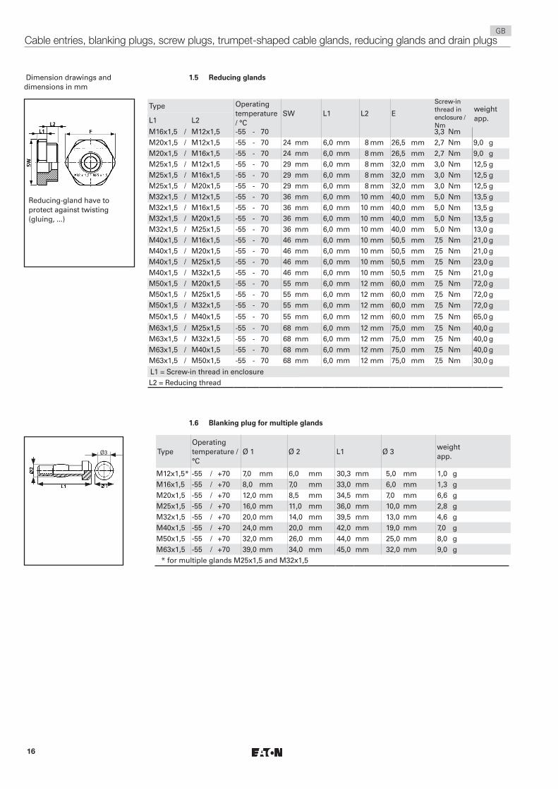
1.5 Reducing glands
Type Operating temperature / °C
SW L1 L2 E
Screw-in thread in enclosure /Nm
weight app.L1 L2
L1 = Screw-in thread in enclosureL2 = Reducing thread
TypeOperating temperature / °C
Ø 1 Ø 2 L1 Ø 3weight app.
* for multiple glands M25x1,5 and M32x1,5
1.6 Blanking plug for multiple glands
Dimension drawings and dimensions in mm
Reducing-gland have to protect against twisting (gluing, ...)
Ø3
GBCable entries, blanking plugs, screw plugs, trumpet-shaped cable glands, reducing glands and drain plugs
M16x1,5 / M12x1,5 -55 - 70 3,3 NmM20x1,5 / M12x1,5 -55 - 70 24 mm 6,0 mm 8 mm 26,5 mm 2,7 Nm 9,0 gM20x1,5 / M16x1,5 -55 - 70 24 mm 6,0 mm 8 mm 26,5 mm 2,7 Nm 9,0 gM25x1,5 / M12x1,5 -55 - 70 29 mm 6,0 mm 8 mm 32,0 mm 3,0 Nm 12,5 gM25x1,5 / M16x1,5 -55 - 70 29 mm 6,0 mm 8 mm 32,0 mm 3,0 Nm 12,5 gM25x1,5 / M20x1,5 -55 - 70 29 mm 6,0 mm 8 mm 32,0 mm 3,0 Nm 12,5 gM32x1,5 / M12x1,5 -55 - 70 36 mm 6,0 mm 10 mm 40,0 mm 5,0 Nm 13,5 gM32x1,5 / M16x1,5 -55 - 70 36 mm 6,0 mm 10 mm 40,0 mm 5,0 Nm 13,5 gM32x1,5 / M20x1,5 -55 - 70 36 mm 6,0 mm 10 mm 40,0 mm 5,0 Nm 13,5 gM32x1,5 / M25x1,5 -55 - 70 36 mm 6,0 mm 10 mm 40,0 mm 5,0 Nm 13,0 gM40x1,5 / M16x1,5 -55 - 70 46 mm 6,0 mm 10 mm 50,5 mm 7,5 Nm 21,0 gM40x1,5 / M20x1,5 -55 - 70 46 mm 6,0 mm 10 mm 50,5 mm 7,5 Nm 21,0 gM40x1,5 / M25x1,5 -55 - 70 46 mm 6,0 mm 10 mm 50,5 mm 7,5 Nm 23,0 gM40x1,5 / M32x1,5 -55 - 70 46 mm 6,0 mm 10 mm 50,5 mm 7,5 Nm 21,0 gM50x1,5 / M20x1,5 -55 - 70 55 mm 6,0 mm 12 mm 60,0 mm 7,5 Nm 72,0 gM50x1,5 / M25x1,5 -55 - 70 55 mm 6,0 mm 12 mm 60,0 mm 7,5 Nm 72,0 gM50x1,5 / M32x1,5 -55 - 70 55 mm 6,0 mm 12 mm 60,0 mm 7,5 Nm 72,0 g
M50x1,5 / M40x1,5 -55 - 70 55 mm 6,0 mm 12 mm 60,0 mm 7,5 Nm 65,0 g
M63x1,5 / M25x1,5 -55 - 70 68 mm 6,0 mm 12 mm 75,0 mm 7,5 Nm 40,0 gM63x1,5 / M32x1,5 -55 - 70 68 mm 6,0 mm 12 mm 75,0 mm 7,5 Nm 40,0 gM63x1,5 / M40x1,5 -55 - 70 68 mm 6,0 mm 12 mm 75,0 mm 7,5 Nm 40,0 gM63x1,5 / M50x1,5 -55 - 70 68 mm 6,0 mm 12 mm 75,0 mm 7,5 Nm 30,0 g
M12x1,5* -55 / +70 7,0 mm 6,0 mm 30,3 mm 5,0 mm 1,0 gM16x1,5 -55 / +70 8,0 mm 7,0 mm 33,0 mm 6,0 mm 1,3 gM20x1,5 -55 / +70 12,0 mm 8,5 mm 34,5 mm 7,0 mm 6,6 gM25x1,5 -55 / +70 16,0 mm 11,0 mm 36,0 mm 10,0 mm 2,8 gM32x1,5 -55 / +70 20,0 mm 14,0 mm 39,5 mm 13,0 mm 4,6 gM40x1,5 -55 / +70 24,0 mm 20,0 mm 42,0 mm 19,0 mm 7,0 gM50x1,5 -55 / +70 32,0 mm 26,0 mm 44,0 mm 25,0 mm 8,0 gM63x1,5 -55 / +70 39,0 mm 34,0 mm 45,0 mm 32,0 mm 9,0 g

17
Fig E
Trumpet-shaped gland
Screw-in thread/ Intermediate gland
Seal
Connection Cable
Type SW L1 L2E width across corners
weight app.
L1 L2
E
SW
TypeOperating tempera-ture
Impact re-sistant
Cable diameterstrain Relief (screws)
Screw-in thread
Trumpet-shaped glandmin. max.
Dimension drawings and dimensions in mm
ATEX type examination certificate:
Marking acc. to 2014/34/EU and standard:
EN 60079-0
IECEx type examination certificate:
Category of application:
IEC60079-0
Perm. storage temperature in original packing:
Degree of protection to IEC/EN 60529: (fully assembled)
1.7 Trumpet-shaped glands M20 to M63
GBCable entries, blanking plugs, screw plugs, trumpet-shaped cable glands, reducing glands and drain plugs
M20x1.5 27 mm 64 mm 15 mm 47 mm 57 gM25x1.5 32 mm 65 mm 15 mm 51 mm 68 gM32x1.5 41 mm 80 mm 15 mm 68 mm 138 gM40x1.5 50 mm 86 mm 15 mm 81 mm 191 gM50x1.5 60 mm 95 mm 16 mm 96 mm 325 gM63x1.5 75 mm 105 mm 16 mm 107 mm 757 g
°C Joule Ø Ø Nm Nm NmM20x1,5 -40 - 85 < 7 8.0 13.0 3.0 1.5 3.5M25x1,5 -40 - 85 < 7 11.0 16.0 3.0 2.0 4.0M32x1,5 -40 - 85 < 7 15.0 20.0 6.0 4.0 7.5M40x1,5 -40 - 85 < 7 19.0 27.0 10.0 6.0 12.0M50x1,5 -40 - 85 < 7 26.0 34.0 30.0 10.0 35.0M63x1,5 -40 - 85 < 7 35.0 46.0 40.0 15.0 45.0
PTB 00 ATEX 3121
II 2 G Ex e II
II 2 D Ex tD A21 IP66 IECEx BKI 08.0007
Ex e II
Ex tD A21 T85°C IP66
-20° C +40° C
IP 66

18
ATEX type examination certificate:
Marking acc. to 2014/34/EU and standard:
EN 60079-0
Einsatztemperaturbereich:
Perm. storage temperature in original packing:
Degree of protection to IEC/EN 60529: (fully assembled)
Einschraubgewinde in Gehäuse:
Prüfdrehmoment:
1.9 Drain plug
TypeOperating
temperature / °CØ 1 L1 L2 L3
Screw-in thread in
enclosure / Nm
weight app.
= Socket head spanner or screw driver, size 8 mm
ATEX type examination certificate:
Marking acc. to 2014/34/EU and standard:
EN 60079-0
(not for M63x1,5)
IECEx type examination certificate::
Category of application:
IEC60079-0 (not for M63x1,5)
(not for M63x1,5)
Perm. storage temperature in original packing:
Degree of protection to IEC/EN 60529: (fully assembled)
M12 - M50
M63
1.8 Screw plugs Dimension drawings and dimensions in mm
GBCable entries, blanking plugs, screw plugs, trumpet-shaped cable glands, reducing glands and drain plugs
PTB 01 ATEX 1128 X
II 2 G Ex e II
-20° C +40° C
-20° C +40° C
IP 66
M25x1,5
5,0 Nm
M16x1,5 -55 / +95 21 mm 12 mm 11 mm 4,0 mm 3,3 2,4 gM20x1,5 -55 / +95 25 mm 13 mm 12 mm 4,0 mm 2,7 4,3 gM25x1,5 -55 / +95 30 mm 13 mm 12 mm 4,0 mm 3,0 6,6 gM32x1,5 -55 / +95 37 mm 15 mm 14 mm 5,5 mm 5,0 12,0 gM40x1,5 -55 / +95 45 mm 15 mm 14 mm 5,5 mm 7,5 36,6 gM50x1,5 -55 / +95 55 mm 16 mm 15 mm 5,5 mm 7,5 56,6 gM63x1,5 -20 / +80 72 mm / mm 12 mm 11,0 mm 7,5 64,5 g
PTB 98 ATEX 3130
II 2 G Ex IIC Gb
II 2 D Ex tb IIIC Db IP66
IECEx PTB 03.0000
Ex IIC Gb
Ex tb IIIC Db IP 66
-20° C +40° C
IP 66
IP 54

19
2 Legende Caution This symbol warns of a possible failure. Failure to observe this caution may result in the total failure of the device or the system or plant to which it is connected.
XATEX - IEC Special conditions:
This symbol indicates that special conditions apply for a safe operation in accordance with the EC Type Examination Certificate / IECEx Certificate of Conformity.
2.1 Safety instructionsThe operations must be carried out by
electrical suitably trained in hazardous area with knowledge of
increased safety explosion protec-tion IEC/EN 60079-14.
All the entries and components listed in these operating and mounting instructions are not suited for use in Zone 0 and Zone 20.
In addition, they may not be used as direct cable entries or seals for flameproof enclo-sures in potentially explosive atmospheres in Zone 1, Zone 2 and Zone 21, Zone 22.
They shall be used for their intended purpose and shall be in a perfect and clean state.
Prior to mounting, check the entries and components, as well as the screw-in threads of the apparatus into which they are to be mounted to ensure that they are in a perfect state.
The requirements of the IEC/EN 60079-0 and EN/IEC 60079-31 regarding excessive dust deposits and temperature to be considered from the user.
The national safety rules and regulations for the prevention of accidents, as well as the safety instructions included in these operating instructions, that, like this text, are set in italics, shall be observed!
3 Conformity with standardsThey have been designed, manufactured and tested according to the state of the art and to DIN EN ISO 9001:2015 and EN ISO/IEC 80079-34:2011.
The apparatus are conform to the standards specified in the EC-Declaration of conformity, enclosed separately.
4 Field of applicationThe entries and components covered by these instructions (see Technical Data) are suited for mounting in potentially explosive atmospheres in Zone 1, Zone 2 and Zone 21, Zone 22 accord-ance with IEC/EN 60079-10-1 and IEC/EC 60079-10-2!
The materials used, including the exterior metal parts, are high quality materials that ensure a corrosion resistance and resistance to chemical substances according to the requirements for use in a ”normal industrial atmosphere”:
- impact resistant polyamide - stainless steel
In case of use in an extremely aggresive atmosphere, please refer to manufacturer
5 Application / PropertiesAll the cable entries and components covered by these operating and mounting instructions are suited for use in enclosures and apparatus in the type of protection ”Increased Safety”.
Trumpet-shaped cable glands are used for feeding flexible cables into enclosures and apparatus.
The fitting of seal inserts one inside the other or the interchanging of seal inserts of different entries to reduce the cable opening is not permitted.
Reducing glands can be used to reduce the size of threaded or through holes in enclosures to a smaller thread size.
Blanking plugs are used to seal metric COOPER CROUSE-HINDS cable entries and COOPER CROUSE-HINDS multiple entries.
Screw glands are used to seal unused through and threaded holes.
Any condensation in the apparatus can escape via drain plugs (see 6.1, Mounting).
Applications other than those described are not permissible without a written declaration of consent from Messrs. COOPER CROUSE-HINDS.
The instructions according to section 7 of the operating instructions shall be observed during operation.
The sole responsibility with respect to the suitability and proper use of these entry components with regard to the basic conditions of these instructions (see Technical Data) lies with the operator.
XATEX - IEC The EC-Type Examination Certificate and any
future supplements thereto shall, at the same time, be regarded as supplements to the EC-Type Examination Certificates PTB 99 ATEX 3128 X and PTB 99 ATEX 3101 X.
GBCable entries, blanking plugs, screw plugs, trumpet-shaped cable glands, reducing glands and drain plugs

20
Through hole
Counter-nut
Fig. 2Enclosure wall
(Wall thickness á 4mm)
Fig. 3
"even" sealing surface
with seal
Pressure screwIntermediate gland
Fig. 1
Enclosure wall (Wall thickness < 4 mm)
Through hole
Pressure screwSeal 1
Fig. 4
6 InstallationThe relevant national regulations and the generally recognized rules of engineering apply for the installation and operation. (IEC/EN 60079-14).
The improper installation and operation of enclosures can result in the invalidation of the guarantee.
Observe the special operational condi-tions accordance to IEC/EN 60069-14.
XATEX - IEC Only fixed cables may be used. The operator
shall ensure that an appropriate strain relief is provided. This is not required for trumpet-shaped glands.
XATEX - IEC The degree of protection IP66 is only
attained if the seals and cable entries are installed correctly.
XATEX - IEC Cable entries that are only suited for a low
impact energy shall be built into an enclosure in such a way as to protect them from a mechani-cal impact energy.
6.1 Mounting
Prior to mounting, ensure that the threads of the entry components match the threads of the apparatus or enclosure.
If the entries and components are to be screwed directly into the walls, the wall thick-ness of the apparatus shall be at least 4 mm.
Counter-nuts shall be used if enclosure walls are less than 4 mm thick. The minimum thickness of the enclosure wall shall be 1.5 mm.
The use of entry elements with damaged or dirty threads can impair the IP degree of protection.
Imported Cables and wiring shall be relieved of tensile forces (eg with a cable clamp).
Special spanner for tightening pressure screws of cable entries
Fig. 5
Screw-in thread
Counter-nut
(with seal for uneven sealing
surface)
Mounting in"uneven"
sealing surface
without seal
Intermediate gland
Seal 2
6.1.1 Cable entries (KLE)
The intermediate gland (see Fig. 1) of the cable entries shall be fitted with a suitable tool, e.g. fork, ring or box spanner.
It is mounted directly in the threaded hole or via the through hole of the enclosure (see Fig. 2).
If the sealing surfaces are uneven, seals shall be used between the enclosure wall and the intermediate gland (see Fig. 3).
Counter-nuts shall be used for walls with a thickness of less than 4 mm (see Fig. 2).
Cables are fed in as shown in Fig. 4.
The seal inserts shall be chosen to suit the respective cable diameter (Page 13 Figs. A, B, C and D).
Use COOPER CROUSE-HINDS spanners with a side opening can be used to facilitate the tightening of the pressure screw when the cable entry has been mounted (see Fig. 5).
Order No. GHG 960 1951 R0001 for Set 1 (M12, 16, 20, 25, 32 and 40)
Order No. GHG 960 1951 R0002 for Set 2 (M50 and M63)
To ensure the required minimum degree of protection, the gland body and the pressure cap shall be tightened with the given test torques (see Technical Data).
When tightening the pressure cap, the gland body shall be prevented from turning with a suitable tool, e.g. a spanner.
Overtightening can impair the degree of protection.
Optionally, cable entries with colour-coded (light blue) pressure screws can be used for intrinsically safe circuits (see main COOPER CROUSE-HINDS catalogue for order numbers).
>5 mm
0 mm
M12, M16 (Ø < 9 mm), M20 ... M63
M16 (Ø > 9 mm)
Ø
Ø
GBCable entries, blanking plugs, screw plugs, trumpet-shaped cable glands, reducing glands and drain plugs

21
Counter-nut
Trumpet-shaped gland
Fig. 8
pressure screw
Blanking plug
Seal 1 + Seal2
Fig. 6
Counter-nut
Fig. 7Seal
6.1.2 Blanking plugsX
ATEX - IEC Blanking plugs of the types GGH 960 6107 P**** or GHG 960 1944 R**** may only be used in conjunction with cable entries of the types GHG 960 92** P**** or GHG 960 19** R**** .
The following shall be observed when mounting blanking plugs for COOPER CROUSE-HINDS metric cable entries (see Fig. 6):
1. Only the blanking plug associated to the KLE shall be used.
2. The head of the blanking plug shall, as shown in Fig. 5, be on the outside.
3. The head of the blanking plug shall, as shown in Fig. 5, be on the outside.
4. The blanking plug shall be pushed into the KLE until it reaches the stop.
5. The pressure screw of the KLE shall be tightened down as described in 6.1.1.
6.1.3 Screw plug
The screw plug shall be screwed tightly into the threaded hole in the enclosure using a suitable tool, e.g. 8 mm socket head spanner or a suitable screw driver.
A counter-nut shall be used for through holes or enclosures that are less than 4 mm thick.
An additional seal shall be used for uneven sealing surfaces.
In general, the M50 screw plug shall be mounted together with the seal supplied.
6.1.4 Trumpet-shaped gland
A suitable tool, e.g. a fork spanner, shall be used for mounting the intermediate gland in the trumpet-shaped gland in such a way that it cannot twist.
It is necessary to ensure that the gland cannot twist once the cable has been fed in and the trumpet-shaped gland mounted (e.g. by using a counter-nut, see Figs. 7 + 8). A counter-nut shall be used for through holes or enclosures that are less than 4 mm thick. When mounting, a seal shall always be used between the enclosure wall and intermediate gland (see Fig. 7).
The following describes the mounting of the cable in the trumpet-shaped gland, as shown in Fig. 8:
1. Cut out the individual rings of the ”onion ring” seal insert to match the respective cable diameter.
2. After feeding in the cable, that has been cut to length and has the seal mounted, into the intermediate gland, screw the trumpet-shaped gland tightly into the intermediate gland to seal off the cable.
3. Then mount the pull relief on the trumpet-shaped gland.
It is necessary to ensure that there is sufficient pull relief, that damage to the cable is not possible and that the trumpet-shaped gland cannot twist.
6.1.5 Reducing gland
A suitable tool, e.g. a fork, ring or box spanner, shall be used for screwing the reducing gland tightly into the threaded hole in the enclosure.
A counter-nut shall be used for through holes or enclosures that are less than 4 mm thick.
An additional seal shall be used for uneven sealing surfaces.
Screwing several reducing glands one inside the other to reduce the size of the entry thread is not permitted.Intermediate gland
Pull relief
Seal inserts
GBCable entries, blanking plugs, screw plugs, trumpet-shaped cable glands, reducing glands and drain plugs