Embed Size (px)
Citation preview

COLLEGE PHYSICSChapter 5 FURTHER APPLICATION OF NEWTON’S LAWS:
FRICTION, DRAG, AND ELASTICITYPowerPoint Image Slideshow

FIGURE 5.1
Total hip replacement surgery has become a common procedure. The head (or ball) of the patient’s femur fits into a cup that has a hard plastic-like inner lining. (credit: National Institutes of Health, via Wikimedia Commons)

FIGURE 5.2
Frictional forces, such as f , always oppose motion or attempted motion between objects in contact. Friction arises in part because of the roughness of the surfaces in contact, as seen in the expanded view. In order for the object to move, it must rise to where the peaks can skip along the bottom surface. Thus a force is required just to set the object in motion. Some of the peaks will be broken off, also requiring a force to maintain motion. Much of the friction is actually due to attractive forces between molecules making up the two objects, so that even perfectly smooth surfaces are not friction-free. Such adhesive forces also depend on the substances the surfaces are made of, explaining, for example, why rubber-soled shoes slip less than those with leather soles.
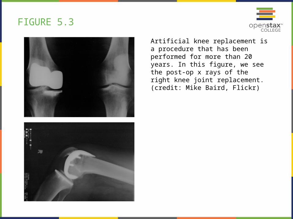
FIGURE 5.3
Artificial knee replacement is a procedure that has been performed for more than 20 years. In this figure, we see the post-op x rays of the right knee joint replacement. (credit: Mike Baird, Flickr)

FIGURE 5.4
The motion of the skier and friction are parallel to the slope and so it is most convenient to project all forces onto a coordinate system where one axis is parallel to the slope and the other is perpendicular (axes shown to left of skier). N (the normal force) is perpendicular to the slope, and f (the friction) is parallel to the slope, but w (the skier’s weight) has components along both axes, namely w⊥ and W// . N is equal in magnitude to w , so there is no motion ⊥perpendicular to the slope. However, f is less than W// in magnitude, so there is acceleration down the slope (along the x-axis).

FIGURE 5.5
Two rough surfaces in contact have a much smaller area of actual contact than their total area. When there is a greater normal force as a result of a greater applied force, the area of actual contact increases as does friction.

FIGURE 5.6
The tip of a probe is deformed sideways by frictional force as the probe is dragged across a surface. Measurements of how the force varies for different materials are yielding fundamental insights into the atomic nature of friction.

FIGURE 5.8
From racing cars to bobsled racers, aerodynamic shaping is crucial to achieving top speeds. Bobsleds are designed for speed. They are shaped like a bullet with tapered fins. (credit: U.S. Army, via Wikimedia Commons)

FIGURE 5.9
NASA researchers test a model plane in a wind tunnel. (credit: NASA/Ames)

FIGURE 5.10
Body suits, such as this LZR Racer Suit, have been credited with many world records after their release in 2008. Smoother “skin” and more compression forces on a swimmer’s body provide at least 10% less drag. (credit: NASA/Kathy Barnstorff)

FIGURE 5.11
Geese fly in a V formation during their long migratory travels. This shape reduces drag and energy consumption for individual birds, and also allows them a better way to communicate. (credit: Julo, Wikimedia Commons)

FIGURE 5.13
A graph of deformation ΔL versus applied force F . The straight segment is the linear region where Hooke’s law is obeyed. The slope of the straight region is For larger forces, the graph is curved but the deformation is still elastic— ΔL will return to zero if the force is removed. Still greater forces permanently deform the object until it finally fractures. The shape of the curve near fracture depends on several factors, including how the force F is applied. Note that in this graph the slope increases just before fracture, indicating that a small increase in F is producing a large increase in L near the fracture.

FIGURE 5.14
The same force, in this case a weight ( w ), applied to three different guitar strings of identical length produces the three different deformations shown as shaded segments. The string on the left is thin nylon, the one in the middle is thicker nylon, and the one on the right is steel.

FIGURE 5.15
(a) Tension. The rod is stretched a length ΔL when a force is applied parallel to its length.
(b) Compression. The same rod is compressed by forces with the same magnitude in the opposite direction.
For very small deformations and uniform materials, ΔL is approximately the same for the same magnitude of tension or compression. For larger deformations, the cross-sectional area changes as the rod is compressed or stretched.

FIGURE 5.16
Gondolas travel along suspension cables at the Gala Yuzawa ski resort in Japan. (credit: Rudy Herman, Flickr)

FIGURE 5.17
Typical stress-strain curve for mammalian tendon. Three regions are shown: (1) toe region (2) linear region, and (3) failure region.

FIGURE 5.18
Shearing forces are applied perpendicular to the length L0 and parallel to the area A , producing a deformation Δx . Vertical forces are not shown, but it should be kept in mind that in addition to the two shearing forces, F , there must be supporting forces to keep the object from rotating. The distorting effects of these supporting forces are ignored in this treatment. The weight of the object also is not shown, since it is usually negligible compared with forces large enough to cause significant deformations.

FIGURE 5.19
Side view of a nail with a picture hung from it. The nail flexes very slightly (shown much larger than actual) because of the shearing effect of the supported weight. Also shown is the upward force of the wall on the nail, illustrating that there are equal and opposite forces applied across opposite cross sections of the nail. See Example 5.5 for a calculation of the mass of the picture.

FIGURE 5.20
An inward force on all surfaces compresses this cube. Its change in volume is proportional to the force per unit area and its original volume, and is related to the compressibility of the substance.

FIGURE 5.21

FIGURE 5.22
Part of the climber’s weight is supported by her rope and part by friction between her feet and the rock face.

FIGURE 5.23
Which method of sliding a block of ice requires less force—
(a) pushing or
(b) pulling at the same angle above the horizontal?

FIGURE 5.24
This telephone pole is at a 90º bend in a power line. A guy wire is attached to the top of the pole at an angle of 30º with the vertical.


![Turbulent Drag Reduction by Biopolymers in Large Scale Pipes · drag reduction by polymers elucidated the role of viscosity profile [5], polymer relaxation time [6], polymer elasticity](https://img.dokumen.tips/doc/110x75/60628fb2149ef01205737169/turbulent-drag-reduction-by-biopolymers-in-large-scale-pipes-drag-reduction-by-polymers.jpg)