Embed Size (px)
Citation preview

International Workshop on Collective Effects and Impedance for B-Factories
12- 17 June, 1995, Tsukuba, Japan
COLLECTIVE EFFECTS AND IMPEDANCE STUDY FOR THE DAΦNE Φ - FACTORY
M. Zobov, P. Arcioni#, R. Boni, A. Gallo, A. Ghigo, F. Marcellini, M. Migliorati,
L. Palumbo°, L. Perregrini#, M. Serio, B. Spataro,
INFN - Laboratori Nazionali di Frascati, P. O. Box 13, I-00044 Frascati (Roma), Italy (#) Università di Pavia, Via Abbiategrasso 209, Pavia, Italy
(°) INFN-LNF and Università di Roma "La Sapienza", P.le Aldo Moro 2, I-00185 Roma, Italy Abstract We describe the design of main impedance generating elements of DAΦNE vacuum chamber and discuss the impact of these elements on single and multibunch beam dynamics.
1. INTRODUCTION The e+e! Φ - factory DAΦNE is presently under construction in Frascati (Italy). It is de-signed as a double ring system with a maximum number of 120 bunches/beam. The short term luminosity goal is L =1.3 !1032cm"2
sec"1 with 30 bunches. The main features of the
factory have been described in details elsewhere [1]. Table 1 gives the relevant parameters of the DAΦNE main rings. The basic design choice of achieving the required luminosity with a large total current, distributed over a large number of bunches, makes the operation very critical with respect to coupled bunch instabilities. These instabilities have been identified since the very beginning of the project as a potentially severe limit on the ultimate achievable luminosity. For this reason, one of the primary goals in the machine design was to reduce to a minimum the number of vacuum chamber elements creating parasitic high order modes (HOMs) capable to drive the multibunch instability and to develop means for damping both the HOMS and the instabilities. This task is accomplished by properly designing the RF cavity and by coupling off the HOMs through loops or wave-guides to extract energy from the resonant fields, thus reducing at the same time the quality factor Q and the shunt impedance R. The residual excitation of beam oscillations is damped by means of a bunch-by-bunch digital feedback system. The single bunch instabilities are also of great importance for DAΦNE. In order to achieve high luminosity in a short machine the single bunch current must be high. This implies that certain single bunch thresholds must be taken into account. Indeed, for DAΦNE, the approximate criterion on the limit of the microwave longitudinal instability [2]:
ZL
n
! "
# $ eff
=2%&(E/ e) '( 0 / E( )
2'z0
I0R (1)
gives a small longitudinal impedance limit
ZL / n( )
eff! 0.01" and the turbulent
lengthening (and widening) regime can hardly be avoided. Here !z0 is the natural bunch length (4.82 mm at Vrf =250 kV).

The energy spread !" and the bunch length are the key parameters defining Touschek lifetime, parasitic losses, luminosity, multibunch instability rise times etc. This demanded careful analysis of the broad-band impedance of the machine (short range wake fields) and simulation of the bunch lengthening process. The transverse mode coupling does not seem to be a limiting instability for DAΦNE as it is for large machines, LEP for example [3]. Nevertheless, the instability can be destructive for the beam and its threshold has to be estimated. The paper is organized in the following way. In Section 2 we discuss the design of the main vacuum chamber elements with analysis of their impedance and possible impact on the beam dynamics. Section 3 describes the results of bunch lengthening simulations and gives estimates for the transverse mode coupling threshold. Section 4 shows the results of the multibunch instability simulations. In the Appendix we summarize formulae which have been used for multibunch instabilities rise time calculations. More details on the subject of the paper can be found in the quoted References.
Table 1. Main DAΦNE Parameters
Energy Average radius Emittance Beam-beam tune shift Betatron tune RF frequency Harmonic number Revolution frequency Max. number of bunches Minimum bunch separation Bunch average current Particles per bunch Momentum compaction Natural energy spread Bunch length Synchrotron radiation loss Damping time RF voltage Synchrotron tune Beta functions at IP Maximum luminosity
E R
! x / !y
!x / !y
!x / !y
f rf h f 0 nb sb I0 N
!
!" 0 / E !z U0
!" / !x Vrf !s
!x
*/ !y
* L
510.0 15.548 1/0.01
0.04/0.04 5.13/6.10
368.25 120
3.0688 120 81.4 43.7
9.0 !1010
0.0058 0.000396
3.0 9.3
17.8/36.0 250
0.0078 450/4.5
5.3 !1032
Mev m
mm.mrad
MHz
MHz
cm mA
cm keV/turn
ms kV
cm
cm-2s-1

2. IMPEDANCE GENERATING ELEMENTS
2.1. RF cavity 2.1.1. RF power requirements DAΦNE is designed to store a maximum current of 5.24 A in 120 bunches per ring at 510 MeV. The RF power per ring, given by the sum of the power delivered to the beam and that dissipated on the cavity walls, is about 100 kW for 120 bunches at 250 kV gap voltage. One 150 kW klystron amplifier per ring will be installed to feed a 368.25 MHz RF cavity. 2.1.2. Shape choice The choice of the cavity shape has been matter of a long debate. The goal was to reduce both the shunt impedance R and the (R/Q) of the cavity HOMs in order to increase the longitudinal instability thresholds. The basic ideas to reduce the HOM impedances were to provide large and long tapered cavity beam tubes to let the parasitic modes propagate along them and to couple out the HOM energy by means of waveguides (WG) [4]. The tapered tubes are used as a gradual transition from the cavity iris to the ring vacuum pipe. A careful analysis of the longitudinal wake potentials made with the code TBCI [5] has shown that in a long taper cavity the loss factor of the HOMs is significantly lower than that of a cavity with short tubes [6]. This means that, on the average, the R/Q values of the parasitic modes are reduced. Two basic cavity shapes, the so called "nose-cone" and "rounded" profiles, were consid-ered. Calculations performed with the computer codes URMEL [7] and OSCAR2D [8] and experimental measurements made on prototypes have shown that the two models are comparable in terms of HOM impedances as illustrated in Table 2. Therefore the rounded cavity was chosen since its mechanical design is much simpler. The cavity shape was then optimized in order to keep the fundamental mode (FM) impedance above 3 MΩ to reduce the dissipated power and make the cooling design easier. Much care was also taken to keep the higher impedance HOM frequencies far away from harmonics of the beam in order to avoid resonant enhancement of the parasitic power losses.

Table 2. Nosecone vs. Rounded
Nosecone Rounded Nosecone Rounded
Frequency (MHz) R/Q (Ω) Q Rs (MΩ) kl (V/pC) k0 (V/pC) kpm (V/pC) kt' (V/pC/m) kpm /k0 kt'/k0 *1 mm
368.3 69.9
34000 2.37 0.101
0.077 0.024 1.16
0.31 0.015
368.3 61.7
49000 3.04 0.129
0.068 0.061 1.38 0.91 0.02
0-MM-1 mode: Frequency (MHz) R/Q (Ω) Q Rs (kΩ) 0-EM-1 mode: Frequency (MHz) R'/Q (Ω) Q Rs' (kΩ)
704.7
4.2 30000
128
565.0 30.3
42000 1.28
696.8 16.0
50000 800
532.7 13.7
54000 0.74
2.1.3. HOM damping and measurements on prototype. HOM damping is obtained by opening rectangular slots onto the cavity surface and applying at those positions rectangular WGs which can convey out of the cavity the fields of the parasitic modes in the TE10 WG dominant mode. The DAΦNE cavity is equipped with five WGs. Three WGs are applied, 120° apart for symmetry considerations, onto the central body. They are 305x40 mm2 rectangular WGs with TE10 cut-off at 495 MHz. Their position allows, on the average, the best coupling with the magnetic field HΦ of the HOMs. One additional 140x40 mm2 WG, with cut-off at 1070 MHz, is placed on each tapered tube to couple some high frequency HOMs which penetrate along the pipes and have intense HΦ at that position. In order to dissipate the HOM power extracted from the cavity, the rectangular WGs are converted in double ridge WGs with a smooth and wideband tapered section which is finally adapted to 50 Ω by a transition to coaxial. The obtained bandwidth is 0.5-3 GHz and 1.2-3 GHz respectively with standing wave ratio (VSWR) < 2 in the full band. Then, by means of coaxial vacuum feedthroughs, the HOM power can be dissipated onto external 50 Ω loads in air [9]. In this way, the application of dissipating materials in ultra high vacuum (UHV) is avoided. Moreover the HOM power can be sampled with directional couplers. The broadband transitions have been designed at LNF with the 3D computer code HFSS [10]. They are manufactured in OFHC copper and have been tested on bench in UHV and with RF power [11].

One broadband transition is shown in Fig. 1. It consists of an initial straight 30 cm section followed by an 80 cm tapered double ridge WG terminated with an adapter to a 7/8" coaxial output. The 30 cm straight allows the fundamental cavity mode to vanish before entering the tapered WG. This avoids having high FM field at the coaxial output. The measured VSWR versus frequency response of the WG to coaxial transition is shown in Fig. 2.
Fig. 1 - Broad band waveguide-to-coaxial transition.
Fig. 2 - Measured VSWR vs. frequency response of waveguide-to-coaxial transition.

With the use of the described damping system, the parasitic mode quality factors Qs of the most dangerous HOMs are reduced, on the average, by two orders of magnitude. In some cases, like for the TM011, the Q damping is even stronger. Frequency and Q of the FM and HOMs have been measured. Also, a careful characterization of the model with the bead perturbation method has been carried out for some longitudinal monopoles to measure their R/Q. Table 3 shows the FM and HOM Qs obtained on a copper cavity prototype equipped with WGs. The last column in Table 3 gives the coupled bunch instability rise time in case of full coupling with the damped HOMs calculated with formulae given in the Appendix. The FM quality factor decreases by 12 % due to the application of WGs.
Table 3. Cavity Prototype Modes
Mode Freq. (MHz) R/Q (Ω) Undamped Q WG
damped Q τ (ms)
0-EM-1 0-MM-1 0-EM-2 0-MM-2 0-EM-3 0-MM-3 0-EM-4 0-EM-5 0-MM-4 1-MM-1 a 1-MM-1 b 1-EM-1 a 1-EM-1 b
357.2 745.7 796.8
1023.6 1121.1 1175.9 1201.5 1369.0 1431.7
490.0 491.3 523.5 549.7
61 16
0.5 0.9 0.3 0.6 0.2 2.0 1.0 5.1* 5.1*
14.0* 14.0*
25000 24000 40000 28000 12000
5000 9000 5000 4000
30500 28500 31500 32000
22000 70
210 90
300 90
180 170 550 650 830 150
50
1.4
14.9 17.5 15.4 25.6 38.4
4.1 2.6 3.0 2.4 4.5
13.1
(*) Normalized impedance, URMEL definition.
2.1.4. Simulations. Simulations of the WG loaded DAΦNE cavity have been carried out using the computer codes POPBCI [12] and HFSS [13] and an analytical method based on the Kirchoff's approx-imation [14]. The code POPBCI can post-process data from any 3D electromagnetic code to calculate the resonant frequencies and the beam coupling impedances of waveguide loaded resonators. The code considers perfectly matched WGs connected to the cavity body and calculates the longitudinal and transverse mode impedances of the resonator as a function of frequency.

Figures 3 and 4 show Re[ZL] and Re[ZT] of the DAΦNE cavity without and with WGs respectively.
Fig. 3 - Longitudinal and transverse coupling impedances of DAΦNE cavity
in the 0 - 1000 MHz frequency band (without waveguide dampers).

Fig. 4 - Longitudinal and transverse coupling impedances of DAΦNE cavity in the 0 - 1000 MHz frequency band (waveguide terminated with perfectly matched loads).

Similar investigations have been performed using the HFSS code which is based on the finite elements method. HFSS computes the field distribution in the frequency domain inside any passive 3D structure by defining input and output ports. The results are presented in the form of a scattering matrix and the parameters Sij versus frequency are given. A different simulation method of the DAΦNE cavity with WG loading is based on the so-called Kirchoff's approximation. The fields propagating in the WGs are computed considering the unperturbed magnetic field on the slot surface as the source term for the WG Green's functions. The Q factor of a generic resonance of the loaded cavity (QL) is therefore:
QL = !U / P0 + Pwg( ) = 1/ 1 /Q0 + Pwg / !U( ) (2)
where Qo is the unloaded quality factor, Po is the power dissipated by the cavity walls and U is the energy stored in the cavity. The power Pwg absorbed by the WGs is given by the real part of the Poynting vector flux through the rectangular slot. This method has been applied to the monopolar modes of the DAΦNE cavity and the re-sults of this analytical simulation are presented in [14]. The results obtained with analytical and numerical methods are in rather good agreement. 2.1.5. HOM power loss estimates. The beam power delivered to the cavity HOMs has been estimated for the 30 bunches initial operation [15] of DAΦNE. The beam current expressed as a Fourier series is: ib(t)= Im! exp jm"0t( ) (3) The total HOM power depends on the cavity monopole spectrum and increases when the beam lines Im overlap the cavity spectrum. The power can finally be derived as follows:
P =2 R /Q( )QIm
2
1 + Q2 m! 0
! r
"!rm!o
#
$ % &
' ( 2
HOMs
)m=0
+*
) (4)
The above expression has been calculated taking into account the beam and cavity spectra. For 30 bunches the HOM power is about 200 W. In the case of full current operation, the HOM losses are below 1 kW per WG.
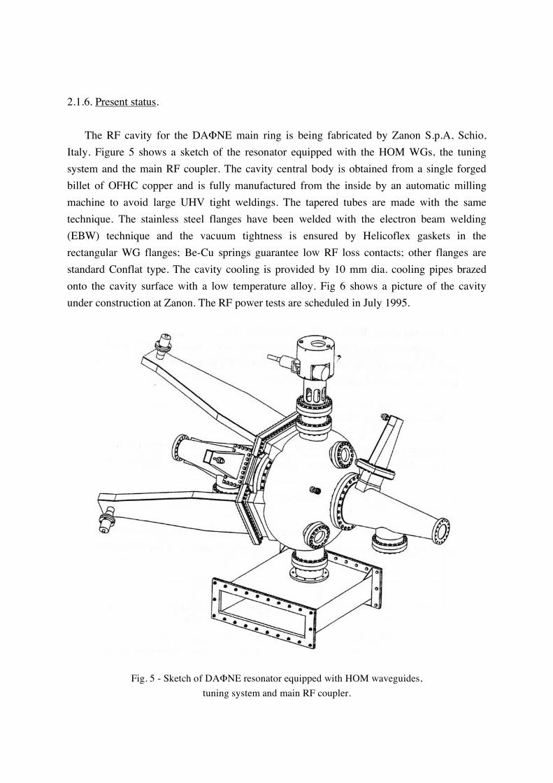
2.1.6. Present status. The RF cavity for the DAΦNE main ring is being fabricated by Zanon S.p.A, Schio, Italy. Figure 5 shows a sketch of the resonator equipped with the HOM WGs, the tuning system and the main RF coupler. The cavity central body is obtained from a single forged billet of OFHC copper and is fully manufactured from the inside by an automatic milling machine to avoid large UHV tight weldings. The tapered tubes are made with the same technique. The stainless steel flanges have been welded with the electron beam welding (EBW) technique and the vacuum tightness is ensured by Helicoflex gaskets in the rectangular WG flanges; Be-Cu springs guarantee low RF loss contacts; other flanges are standard Conflat type. The cavity cooling is provided by 10 mm dia. cooling pipes brazed onto the cavity surface with a low temperature alloy. Fig 6 shows a picture of the cavity under construction at Zanon. The RF power tests are scheduled in July 1995.
Fig. 5 - Sketch of DAΦNE resonator equipped with HOM waveguides, tuning system and main RF coupler.

Fig. 6 - DAΦNE cavity under construction at Zanon.
2.2. Longitudinal feedback kicker Even though the HOMs in the accelerating cavity are heavily damped, the probability for a damped HOM to cross a coupled bunch mode frequency is high and, due to the large total current, the growth rate of unstable modes can be substantially stronger than the natural damping rate (compare the data of Table 3 with radiation damping times given in Table 1).

The required additional damping is provided via a time domain, bunch by bunch feedback system [16] based on digital signal processors (DSPs). The digital section is under construction at SLAC in the framework of a collaboration with the SLAC-LBL PEP-II group on feedback systems for the next generation of factories with intense beams and a large number of bunches. In fact, the design specifications are set to meet the ultimate performance specifications of ALS, PEP-II and DAΦNE. A prototype system with a single board digital section is running at ALS [17]. The maximum power at the kicker is determined by the voltage gain needed to achieve the required damping rate and the maximum synchrotron phase error allowed during injection. We have some new development with the longitudinal kicker. We have built a prototype with two full coverage striplines broadly resonant at ~ 1.2 GHz, i.e.: 3.25 times the RF fre-quency, series connected with a λ/2 line. We have experimented with little surprise how awk-ward can be proper tuning of this device. Furthermore, according to simulations, the stripline kicker is very rich in HOM content, requiring a careful laboratory characterization. Therefore, we have explored the possibility to use an RF cavity kicker whose fundamental mode resonates at 3.25 times the RF frequency. Figure 7 shows a cut view of the cavity. The 88 mm diameter beam tube opens into a 200 mm diameter, 72 mm long, pill-box cavity. To obtain the very large bandwidth required (≈ 180 MHz at least, for 120 bunches operation), the cavity is loaded by 6 ridged waveguides followed by broadband transition to 7/8" standard coax, very similar to those in the main RF cavity, except that in this case the coupling is extended to the fundamental mode. The 6 waveguides are placed symmetrically on both sides of the pill box 120° apart from each other. Three WGs are used as input ports and the other three for termination loads. In this way, thanks to the symmetry and since the power dissipated in the external load is much greater than the power dissipated in the cavity walls, the system is perfectly matched. The kicker cavity does not need to be tuned in operation, being broadband, nor cooled, since almost all the power is dissipated in the external loads. Moreover, the damping waveg-uides couple out the HOM's as well. The behavior of the device has been completely characterized making use of the HFSS as the fundamental design tool. A cavity kicker prototype has been recently built and measured at LNF. Figure 8 shows the theoretical and experimental transmission frequency response for the fundamental mode and HOMs up to beam pipe cut-off. A 750 Ω peak shunt impedance, to be compared to the theoretical 400 Ω (measured in a prototype: ≈ 300 Ω) in the stripline, together with a bandwidth larger than 220 MHz have been calculated and measured. The results are shown in Fig. 9.

The mechanical design is now complete and we intend to place an order to industry for two pieces (one per ring) for the initial operation at a reduced number of bunches. According to simulations with realistic values of the HOM impedances, a large bandwidth power amplifier of ~ 200 Watt is enough to damp an initial offset of 100 ps of the injected bunch with the other 29 bunches at the full design current. Two cavities per ring will eventually be installed for operation at the full nominal current with 3x200 Watt power amplifiers per cavity, each feeding separately a waveguide coupler. The stripline kicker is a directional device operating in travelling wave mode, and therefore its input downstream ports are almost uncoupled to the beam. On the contrary the cavity kicker is a totally symmetric standing wave structure so that the power released by the beam reaches indifferently all ports. Ferrite circulators are therefore necessary in this case to isolate the output section of the power amplifier feeding the cavity.
Fig. 7 - Cut view of longitudinal feedback kicker cavity.

Fig. 8 - Theoretical and experimental WG to WG transmission frequency response
of longitudinal feedback kicker cavity.

Fig. 9 - Shunt impedance of longitudinal feedback cavity kicker.

2.3. Resistive wall The resistive wall impedance per unit length is given by [18]:
ZL
L=!
c
(1 + j)Z0"
4#bF0
b
a
$ %
& '
ZTx
L=
(1 + j)Z0"
2#b3F1x
b
a
$ %
& '
ZTy
L=
(1 + j )Z0"
2 #b3F1y
b
a
$ %
& '
(5)
where
! =2c"
#Z0 (6)
is the skin depth; ! the material resistivity; Z0 the free space impedance (120π Ω).
F0,F1x ,F1y are the form factors depending on the geometrical shape of a vacuum chamber cross section, b stands for half the vertical chamber size and a is half the horizontal one. Almost all the DAΦNE vacuum chamber is made of aluminum, except for a 60 cm long
beryllium vacuum pipe in the vicinity of the interaction point and relatively short pieces of
stainless steel pipe coated with 40-50 µm copper. The vacuum chamber in the bending
magnets is of rectangular shape with cut corners which can be approximated by an ellipse
with axes 53! 100 mm and F0 = 0.95, F1x = 0.47,F1y = 0.845. The beam pipe in the
straight sections has a circular cross section with radius b = 44 mm for which
F0 = F1x = F1y = 1. The very flat rectangular vacuum chamber inside the wiggler magnets
(20! 130mm) can be represented in calculations by two infinite parallel plates with
F0 = 1,F1x =
!2
24,F1y =
!2
12.
By summing up the three contributions, the total longitudinal and transverse resistive wall impedances are:
ZL = 0.3(1 + j) n ! , ZTx = 15.34(1 + j) / nk!
m, ZTy = 28.27(1 + j) / n
k!
m Here n is the harmonic number f/fo.

For a thick wall and not very short bunches the loss factor and the dissipated power per unit length due to the resistive wall impedance are given by:
dkl
dz=
c
4!2b"z
3/2
Z0#
2$3
4
% &
' ( F0;
dP
dz=
(eN )2 nbc
2!R
dkl
dz (7)
where N is the number of particles per bunch and nb is the number of bunches in the beam. Then, in the case of 120 bunches, the power deposited in the straight sections is 6.9 W/m, in the bending magnet vacuum chamber 10.9 W/m and in the wiggler vacuum chamber 30.4 W/m. The longitudinal impedance estimated at the bunch spectrum roll-off n = 520 is a rather small value
ZL
n= 0.013(1 + j )!
and is not considered to be harmful for the longitudinal single and multibunch beam dynamics while the transverse impedance is dominant at low frequencies and can excite the transverse multibunch instability. We have evaluated the transverse instability rise time [19] using the well-known expression for the coherent frequency shift [20, 21]. Figure 10 shows the rise time for the first three transverse coherent modes as a function of the machine chromaticity ! for 30 bunches in the beam.
Fig. 10 - Rise times of transverse resistive wall instability for monopole (m = 0), dipole (m = 1) and sextupole (m = 2) modes.

As we can see, the rise time of the monopolar mode (m = 0) for a slightly positive chromaticity is about one order of magnitude faster than the DAΦNE transverse damping time. A transverse feedback system is necessary to damp this instability.
2.4. Transverse feedback kicker A transverse feedback system is foreseen in order to damp the resistive wall instability and control a large number of transverse coupled bunch modes. The system utilizes two button beam position monitors in order to detect both the horizontal and vertical beam momenta; summing the pick-up signals in proper proportion, the correction signal (in quadrature) at the kicker is produced. Two transverse kickers will be installed in each ring; these kickers are of stripline pair design (see Fig. 11), with one device per transverse plane. In order to use the stripline as transverse kicker, two voltages of opposite polarity are applied downstream the beam direction at facing ports. The combined magnetic and electric fields give a deflecting Lorentz force in the transverse plane.
Fig. 11 - Sketch of transverse feedback kicker.
The striplines are chosen to be 20 cm long; the stay clear aperture of the devices is 88 mm (the beam pipe diameter) and the vacuum chamber diameter in this section is 120 mm. The available space in the machine limits the maximum length of each kicker. Two 50 mm long tapers join the kicker vacuum chamber to the rest of the beam pipe in order to minimize the losses. The electromagnetic project has been realized with the HFSS computer code optimizing the feedthrough positions, in order to minimize the reflection to the amplifier. The calculated fraction of the input power reflected to the amplifier is less than 2%.

The transverse shunt impedance versus frequency on axis is shown in Fig. 12.
Fig. 12 - Transverse shunt impedance of transverse feedback kicker (solid line - analytical result; points - HFSS numerical simulation result).
The coupling impedance of the kicker at low frequencies can be evaluated as the impedance of a pair of striplines [22]:
ZL(! )= 2Zs"02#
$ %
& '
2
sin2!l
c+ j sin
!l
ccos
!l
c
$ %
& '
ZT((! )=
c
b24
"0
$
% ) &
' * 2
sin2"02
$ %
& ' ZL
!+ ,
- .
(8)
where Zs is the characteristic impedance of the transmission line formed by a strip and the vacuum chamber wall; l is the stripline length; !0 the stripline coverage angle; ZT
! is the transverse impedance in the direction perpendicular to the striplines.

At frequencies ! / 2" << c / 4l = 375MHz eq. (8) gives for such a kicker:
ZL
n! j2Zs
"02#
$ %
& '
2l
R= j0.064(
ZT) ! j
8Zsl
#2b2sin
2 "o2
$ %
& '
= j1.73k(
m
(9)
Due to the periodic behavior of (8) these values have to be considered as an upper limit in the low frequency range. The maximum value of the real part of the impedance ReZL / n within the low frequency range is 0.04! at f = 375 MHz. Analysis of high frequency kicker behavior with MAFIA and HFSS have shown that some HOMs do not couple to the feedthroughs and remain trapped in the kicker structure. The strongest is the mode at f = 2.303 GHz with Rs = 2.67 kΩ and Q = 1971. The longitudinal coupled bunch instability rise time is about 1 ms at full coupling. If this happens the instability can be damped, in principle, by the longitudinal feedback system. But the power loss due to the mode can be high. Although the mode is at the tail of the bunch spectrum (for 3 cm bunch length), it is close to the spectrum line 25 ! (30 f 0 ) = 2.302 GHz in the 30 bunches operation. There is a high probability of full mode coupling with the spectrum line. This would give 1 kW power loss. In order to extract this mode we plan to install an antenna on the kicker taper. 2.5. Interaction region The interaction region (IR) for the KLOE experiment [23] is 10 m long and is shown in Fig. 13. The low-! permanent quadrupole triplets are 46 cm away from the interaction point (IP) and are confined in a cone of 9o half aperture, leaving a material free solid angle for the apparatus of ~ 99%. It is a requirement of the experiment to have a large (radius 10 cm) aper-ture vacuum chamber at the IP as transparent as possible to the produced particles. The outer parts of the IR vacuum chamber are made of stainless steel with a copper coating inside to reduce the ohmic losses. The inner section, bulb-shaped at the IP, is made of 0.5 mm thick pure beryllium, directly brazed onto the stainless steel pipe. The beryllium bulb-shaped cavity (see Fig. 14 for details) is harmful to the beam dynam-ics. It traps both monopolar and dipolar HOMs which can result in longitudinal and transverse multibunch instabilities and excess RF power loss [24]. Table 4 shows the parameters of three dangerous monopole modes while Table 5 gives estimated rise times for the dipole mode and quadrupole mode instabilities, !1 and !2 , respectively.

Fig. 13 - KLOE interaction region layout.

Fig. 14 - Central part of interaction region vacuum chamber.
Table 4. Modes trapped in the spherical part of IR
f [MHz] R/Q [!] Q
1324.2 1877.1 2353.8
15.2 14.0
7.45
34500 36100 37100
Table 5. Power losses and instability rise times
f [MHz] !1 [ms] !2 [ms] P1 [W]
1324.2 1877.1 2353.8
0.006 0.006 0.011
0.012 0.008 0.011
1109.4 531.2 131.1
Note that the dissipated power may be enormous even for a single bunch rotating in the machine when full coupling of the HOM with the closest bunch spectrum line occurs (P1 in Table 5). This situation has a rather high probability since the spectrum lines are situated at each harmonic of the revolution frequency and due to the temperature drift the HOM can be moved on a spectrum line.

The possibility of using long tapers from the IP to the first quadrupole magnet instead of the beryllium cavity also has been investigated. It was shown that this would not remove the problem of trapped modes completely and, what is even more important, such a thin beryllium structure could collapse under the 1-2 atm. pressure [25]. In order to avoid RF radiation a solution with a thin Be screen of 50-60 µm thickness has been proposed. Its radius is equal to that of the beam pipe and the length ! 20 cm, shielding the bulb-shaped part of the vacuum chamber. This thickness is enough to screen frequencies starting from the first harmonic of the revolution frequency and, on the other hand, transparent for the experiment. The total estimated resistive wall loss in the screen is about 4 W in case of 120 bunches in both electron and positron beams. The synchrotron radiation produces only a small additional heating of the beam pipe (1-2 W) near the IP [26]. The first Be sample prototype has been delivered from K-TEK and is under test at the Frascati Laboratory. The tapers in the IR are very smooth and give mainly an inductive contribution to the impedance (see below). The IR for the FINUDA experiment [27] is simpler because the vacuum chamber near the IP is just a cylindrical Be pipe.
2.6. Vacuum port screen Lumped vacuum ports in the straight sections are screened by a mesh of rounded end 22 mm long and 8 mm wide longitudinal slots. The longitudinal distance between slots is varied randomly within ±10% in order to break the periodicity and destroy possible coherent buildup of the wave radiated by the slots [28]. The low frequency longitudinal and transverse impedance of a slot in a circular vacuum chamber of radius b is calculated analytically [29]:
ZL !( ) = jZo!
c
"m + " e( )4#2b2
ZT !( ) = jZo
"m + " e( )#2b4
r a s cos($s % $b )
(10)
where !e and !m are the electric and magnetic polarizabilities;
r a s is the unit vector directed
onto the slot ; !s and !b are azimuthal angles of the slot and beam in the vacuum chamber cross section containing the slot.

For slots with rounded ends and 0.1 ! w / l ! 1 , where w is the slot width and l the slot length, !e and !m can be found with an accuracy better than 1% by applying the following approximations [30]:
!e " #$
16w2l 1 # 0.765
w
l+ 0.1894
w
l
% &
' (
2) * +
, - .
!m "$
16w2l 1 # 0.0857
w
l# 0.0.0654
w
l
% &
' (
2) * +
, - .
(11)
For a single pump screen containing 90 slots eq. (10)-(11) give:
ZL
n= j1.68 ! 10
"3# and ZT = j27.0
#
m
In the case of DAΦNE the bunch is longer than the slot sizes and the low frequency formulae (10)-(11) are valid almost for all the bunch spectrum. The real part of a slot impedance is much smaller than the imaginary one and has been calculated in [31]:
ReZL !( ) = Z0
" e2 + "m
2( )6#3b2c4
!4 (12)
The corresponding loss factor is :
kl = Zo
!e2 + !m
2( )c16"7/2#
z
5b2
(13)
An estimate for the DAΦNE pump screen gives the negligible value
kl = 2.8 !10
"5V / pC .
We should mention that the expressions (12), (13) were obtained for infinitely thin vacuum pipe walls. Due to the finite thickness of the beam screen, which is comparable to the slot width in the DAΦNE case, some additional reduction of the impedances (~ 60%) is expected.

2.7. Antechamber slots Four 10 m long vessels constitute the vacuum chamber of the bending and wiggler sections of each ring. A continuous 10 m long slot separates the beam channel from an antechamber where the synchrotron radiation absorbers and the pumping stations are situated. The width of the slot very smoothly changes between 20 mm at the absorber location and 10 mm in the wiggler vacuum chamber. Different cross sections along the bending section are shown in Fig. 15. The depth of the slot is always longer than its width. This attenuates beam coupling to the antechamber. In order to estimate the beam impedance, calculations were carried out with MAFIA (see Fig. 16). Due to the known fact that the dependence of the impedance on the slot length satu-rates for long slots we assumed for the simulation a 50 cm long slot which, being much longer that the bunch, is adequate to describe the slot impedance. The slot width was taken to be 2 cm and the depth 2.5 cm. The coupling impedance was found by performing the Fourier transform of the long range wake field given by MAFIA. Figure 17 shows the real and imaginary part of the impedance. As it can be seen, the impedance is small and mainly inductive up to rather high frequencies. The low frequency part of the impedance is less than ZL / n = j6.6 ! 10
"5# . No dangerous HOM were found in
such a structure.
Fig. 15 - Some of arc vacuum chamber cross sections (only half of the arc is shown).

Fig. 16 - MAFIA input for antechamber slot impedance calculations.
Fig. 17 - Real and imaginary part of the antechamber impedance.

2.8. Beam position monitor (BPM)
The beam position monitor (BPM) system is the primary diagnostic system. We have 41 BPMs in each ring and 12 in the common part of the interaction regions. They consist of four "button" electrodes mounted flush with the vacuum pipe. The design helps maintaining cou-pling impedance and parasitic losses within acceptably low values in spite of the large number of units. Since the vacuum chamber cross-section is largely variable along the ring circumference, we have developed six different designs, but in all of them the same type of electrode (SMA 50-MB from Ceramex, France) is used (see Fig. 18).
Fig. 18 - Button electrode for DAΦNE BPMs.
The button electrode is mainly sensitive to the beam electric field. The usual equivalent circuit representation of an electrostatic monitor is a current generator of the same value of the image current intercepted fraction, shunted by the electrode capacitance to ground (~ 5pF in our case). The button is connected to the detector circuit by means of a short run of coaxial cable having characteristic impedance Ro = 50 Ohm and terminated into an Ro resistor.

Taking a circular vacuum chamber of radius b as reference, it is useful to write the signal impedance ZB for a centered beam as:
ZB = F!R0j" / "2
1 + j" / "1 (14)
where ω1 = 1/RoCB and ω2 = c/2r, with CB the button capacitance to ground, r the button ra-dius, c speed of light, ϕ the coverage factor = r/4b and F a form factor depending on the chamber geometry and on the electrode position in the chamber (F = 1 for circular geometry). In this way the signal impedance is written as a frequency-depending part which is a function of the button characteristics (radius and capacitance to ground, equal for all the BPMs) times a constant factor including geometric factors and the termination resistance. In the various BPM designs the values of F range from ~ 0.7 to 1 and the values of ϕ from ~ 0.03 to 0.125. Following the arguments of Ref.[32], the low frequency component of the longitudinal coupling impedance (per button) can be written as
ZL(! )= "!1!2
#
$ % &
' ( ZB(! ) (15)
and
ZL
n= F! 2R0
"1"2
#
$ % &
' ( j"0 / "21 + j" / "1
(16)
with ω0 the angular revolution frequency. Note that for a matched electrode (ω1/ω2) = 1. Taking into account all the BPMs, this gives a fairly small value (3.3.10-3 Ω) for Z/n, with the imaginary part mainly inductive at low frequency and vanishing at high frequency and a maximum of the real part at a frequency f = ω1/2π. However, this method of evaluation of the coupling impedance is likely to underestimate the result, since it takes into account only that part of fields contributing to the output signal formation. In fact, some modes which do not dissipate their power in the external terminations, have been found with MAFIA. The first one is the mode of TE11 type establishing around the electrodes. Since the electric field is maximum at the button circumference and zero at the center connection, no signal is generated outside. The frequency of the mode (~7 GHz) is beyond the bunch spectrum and does not give any substantial contribution to the power loss. Neither it is dangerous for the multibunch stability.

The same is valid for the other modes of that kind at higher frequencies. However, these modes give some additional inductive contribution to the impedance at low frequency. The low frequency impedance of a BPM can be evaluated as the impedance of an annular narrow slot in the vacuum chamber wall. Since the polarizabilities are not known for the slot we calculated the inductive impedance of a single button with MAFIA and applied eq. (10) as a scaling law for different BPM designs taking into account also the geometry of the vacuum chamber and the button position in it. For all BPMs such an estimate gives Z
L/ n < 0.01 !.
2.9 Tapers In order to reduce the coupling impedance it is necessary to produce a vacuum chamber as smooth as possible. Long tapers, connecting vacuum chamber components, are used in DAΦNE to avoid sharp discontinuities in the vacuum chamber cross section. The diameter of the beam pipe in the interaction region increases from 88 mm at the interaction point to 200 mm at the gate valve location at a distance of 3.3 m from the IP by means of a system of very gradual azimuthally symmetric tapers, shown in Fig. 13. After the valve, a 1.1 m long taper with the angle less than 4o is used to connect the 200 mm round beam pipe to the 200! 54 mm rectangular pipe in front of the splitting magnet. Simulation of such a structure with ABCI gives a low frequency inductive impedance ZL / n = j0.033 ! and a loss factor kl = 2.58 !10
"3V / pC for 3 cm bunch length.
Smooth transitions connect the circular beam pipe of the straight sections (with a diameter of 88 mm) and the rectangular beam pipes after the splitting magnet (88! 54 mm). Figure 19 shows an example of such a connection between the rectangular chamber in the splitting magnet and the straight section. The tapers between the rectangular dipole vacuum chamber and the straight section are essentially the same, but steeper (with the angle of
13.9o) due to the limited space allowed. For the taper impedance estimates, in simulations
with ABCI, we use an azimuthally symmetric structure and then multiply the results by the azimuthal filling factor. Summing up the contributions from all the tapers of that kind gives ZL / n = j0.063 ! . There are other tapers between the rectangular vacuum chamber in the bending sections and the very flat rectangular chamber inside the wiggler magnets (130! 20 mm). These tapers are the closest to the beam and to decrease their influence on the beam dynamic the taper angle has to be as small as possible. In the present design the angle is less than 2.5o . The total contribution of the tapers in 4 wiggler section is ZL / n = j0.027 ! .

Fig. 19 - Transition between rectangular and round beam pipes.
2.10. Scrapers A scraper system [33] will be used in DAΦNE to reduce the lost particles background in-side the KLOE and FINUDA detectors. It consists of two vertical and two horizontal scrapers in each ring. Fig. 20 shows the horizontal scraper. The central part of the scraper (target) is made of W and has a thickness of 5 cm to stop almost completely the electromagnetic shower produced by 500 MeV electrons. In order to minimize the contribution of such a discontinuity to the coupling impedance the target joins the neighboring vacuum chamber by means of long tapers in the beam direction which are made of a lighter material. During machine operation the position of the scraper can be varied to find a compromise between a good life time and an acceptable background in the detectors. At injection the scrapers must be open to exploit the whole available aperture. The impedance calculations were carried out for the case of maximum target penetration into the vacuum chamber. Figure 21 shows the real and imaginary part of the impedance calculated as Fourier transform of the wake field given by MAFIA. The impedance remains inductive until ~3 GHz and the low frequency contribution can be estimated as j0.0155 Ω. The design of the vertical scraper is the same, except that the targets are moved in the vertical direction and the maximum penetration is smaller than the horizontal one.

Fig. 20 - Horizontal scraper design.
Fig. 21 - Horizontal scraper broad band impedance.

2.11. Bellows The mainly inductive contribution to the beam impedance is expected from bellows con-necting the machine arcs with the straight sections. The bellows have to allow both the longi-tudinal expansion and the bend in the horizontal plane. It was decided to avoid any sliding contacts in the bellows which can be burned out due to the high current flowing on the bellows screen. Moreover, if, for any reason, there is no contact between the sliding surfaces the capacitance between the sliding contacts can create a resonant circuit with the rest of the bellows. This is a potential danger for the multibunch stability and a source of power losses. The bellows design proposed for DAΦNE is shown in Fig. 22. The bellows screen is made of thin (0.5 mm) strips oriented in the vertical plane and separated by 4 mm gaps. The width of a strip is 6 mm, i. e. wider than the gap between the strips in order to attenuate radia-tion outside the screen.
Fig. 22 - Bellows design. The strips are produced by a hot forming method and have a waved shape. This allows longitudinal expansion. In the working regime the strips are supposed to be almost straight. Preliminary simulations with MAFIA show that the bellows are inductive at low frequency with a rather small impedance of ZL / n = j0.006! . Simulations in frequency domain indicated a cluster of low shunt impedance low Q HOMs with wave length ! = 2l , l being the length of the slots between the strips. However, we can not completely rely on the numerical simulation for such a complicated structure which were carried out with a rough mesh due to memory and CPU time limitations. Because of that a bellows prototype was ordered to DOIG SPRING, UK and the coupling impedance will be measured.

2.12. Other inductive elements There is a large number of small discontinuities in the DAΦNE vacuum chamber, of different kinds, shapes and sizes. These are shallow cavities in flanges and valves, gaps in BPM assembly, slots for the synchrotron radiation monitor etc. Due to the limited space allowed, we do not show the corresponding drawings. Despite of small sizes, the overall contribution of these elements to the inductive impedance, up to rather high frequencies, can not be neglected. We have used both the analytical expressions of [34] and numerical simulations with ABCI in order to evaluate the contribution. The overall estimated impedance ZL/n is smaller than j0.1 Ω. 2.13. Space charge impedance, Laslett tune shift The space charge coupling impedance of a uniform disk beam with transverse size "a" in a smooth round beam pipe of a radius "b" is purely imaginary [35]:
ZL
n= ! j
Z0
2" 21 + 2 ln
b
a
# $
% &
'
( ) *
+ , (17)
ZT = ! jZ0R
" 21
2a2!1
b2# $
% &
(18)
To give an estimate we take a =< ! y > , which is the smallest average transverse size and b = 2.65 cm as an average beam pipe radius. This gives:
ZL
n= ! j2.1m" and ZT = ! j114.9k" /m
The Laslett tune shift [36] for a tri-gaussian bunch can be written in the following form [37]:
!"y = #NT / B( )$ yre
2%$2& 3'y 'x + 'y( )#NT$ yre
%&
1
$2& 2B
(1h2
+(1h2
+(2g2
) * +
, - .
(19)
where NT is the total number of particles in the ring;
B = 2!"z / sb is the bunching factor
with sb the bunch spacing; h is the half-height of the vacuum chamber; g is the half-height of the magnetic gap. The coefficients !1 and !2 are the form factors for the vacuum chamber and magnetic gap (can be found, for example, in [38]).

The first term in (19) is a direct space charge term !"ysc and can serve as a measure of
the space charge tune spread in a bunch [37]. For DAΦNE it is negligible:
!"y
sc= #4.4 $ 10
#4 (120 bunches)
i. e. about two orders of magnitude smaller than the beam-beam tune spread. The second term in (19) is due to induced charges and currents in the vacuum chamber walls and magnet poles. A rough pessimistic estimate gives for DAΦNE:
!"y
ind= #1.16 $10
#2 (120 bunches) which can be compensated, if necessary, by adjusting the machine linear optics. Here we have considered only the vertical tune shift because the direct space charge term is much smaller for the horizontal plane due to the larger horizontal beam size and, in turn, the second term gives a slightly smaller value than !"y
ind but of the opposite sign.
3. SINGLE BUNCH THRESHOLDS
3.1. Bunch lengthening In the study of the single bunch dynamics, the wake potential over the bunch length is of main interest. This implies that, in the frequency domain, the bunch does not resolve the details of the actual machine impedance and it rather experiences an average effect. The reduced frequency resolution was the main justification for using different broad-band models, when the machine impedance is substituted by a simple model with a limited number of parameters, extracted from the results of experiments or numerical simulations. However, when the bunch length changes over a wide range the parameters of the model essentially depend on the bunch length. For example, the wake of an RF cavity can be induc-tive for long bunches and capacitive for short bunches. For DAΦNE, where the bunch length changes from a "natural" length of 5-6 mm to the nominal value of 3 cm, it is impossible to characterize the broad-band impedance of a vacuum chamber element by a single value at different bunch lengths. In order to get an idea of the relative contributions of the elements to the total machine impedance, in Table 6 we show the contribution of the main inductive elements (remaining inductive in the foreseen bunch length range), while Table 7 shows the loss factors of the elements contributing to the power loss at the nominal bunch length.

Table 6. Impedance of main inductive elements
Element Im ZL/n [Ω] Tapers Transverse feedback kickers (low frequency) Scrapers Bellows Resistive wall (at roll - off frequency) BPMs Vacuum pump screens Injection port Antechamber slots Synchrotron radiation Space charge Other inductive elements
Total
0.156 0.128 0.062 0.024 0.013 0.01 0.02 0.0031 0.0005
< 0.015 -0.0021 0.1
0.53 Ω
Table 7. Elements contributing to power losses
Element kl ,V / pC at σz = 3 cm
RF cavity Third harmonic cavity Longitudinal feedback kicker Transverse kickers Injection kickers IR taper system Scrapers Injection port
Total
0.129 0.157 0.120 0.064 0.047 0.0026 0.00007 0.00004
0.52
In order to simulate the bunch lengthening process we undertake a numerical tracking using the wake potential of a short gaussian bunch with !z = 2.5 mm (see Fig. 23) as the machine wake function. The computer codes ABCI [39] and MAFIA were used to calculate the wake potential for DAΦNE.
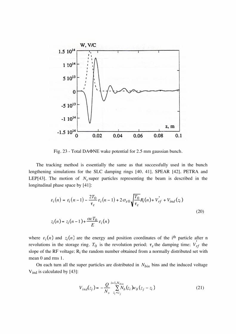
Fig. 23 - Total DAΦNE wake potential for 2.5 mm gaussian bunch. The tracking method is essentially the same as that successfully used in the bunch lengthening simulations for the SLC damping rings [40, 41], SPEAR [42], PETRA and LEP[43]. The motion of Ns super particles representing the beam is described in the longitudinal phase space by [41]:
!i n( ) = !i n "1( ) "2T0
#!!i n " 1( ) + 2$! 0
T0
#!Ri(n)+ Vrf
' + Vind (zi )
zi(n)= zi(n "1)+%cT0E
!i(n)
(20)
where !i(n) and zi(n) are the energy and position coordinates of the ith particle after n revolutions in the storage ring. T0 is the revolution period; !" the damping time;
Vrf
' the slope of the RF voltage; Ri the random number obtained from a normally distributed set with mean 0 and rms 1. On each turn all the super particles are distributed in Nbin bins and the induced voltage Vind is calculated by [43]:
Vind(zj )= !Q
Ns
Nb(zi )w"zi <z j
i=1,Nbin
# (zj ! zi ) (21)

Note, that zj in the expression (21) are the coordinates of the bin centers and the induced voltage at the positions of the super particles is found by a linear interpolation over the
Vind (zj ). Here Nb(zi ) is the number of super particles in the bin with the center at zi and
w! (z) is the machine wake function. For the simulation we have used Vrf = 127 kV . This corresponds to the natural bunch length of 6.8 mm. Ns = 200000 particles are tracked over 4 damping times and the average bunch properties, as rms length, rms energy spread, coordinate of the centroid, are calculated by averaging over the last damping time. These bunch characteristics with the bunch distribution are shown in Fig. 24. The bunch distribution gets more bulbous than a gaussian and is tilted forward. Such a distribution corresponds to the inductive - resistive machine broad-band impedance.
Fig. 24 - Bunch lengthening in DAΦNE at Vrf = 127 kV: a) Bunch shape; b) Bunch centroid coordinate; c) Relative rms energy spread;
d) rms bunch length as intensity function.

As it can be seen in Fig. 24c) the microwave threshold is at N = 1 !1010 particles per
bunch. Despite such a low threshold the bunch length still does not reach the nominal value of !z = 3cm. We should remark here, that in the simulation we did not included the impedance contribution from the bellows between the machine arcs and straight sections be-cause their final design was not finalized yet. The wake fields due to the bellows give some bunch length increase. Nevertheless, a third harmonic cavity is foreseen for DAΦNE as an additional means for the bunch length control [44, 45].
3.2. Transverse mode coupling threshold In order to estimate the threshold average current (Io)th for the transverse mode coupling instability in DAΦNE we use the approximate formula [21] which is valid for the coupling of lowest transverse modes ( m = 0 and m = -1 ):
I0( )th=
4 E / e( )!sR Im ZT[ ]" y #
4 $
3% z (22)
Here the imaginary impedances of vacuum chamber elements must be summed up weighting by the betatron function at their locations. The bunch arriving from the accumulator ring is expected to be longer than 3 cm and, due to the fact that the synchrotron period is two orders of magnitude shorter than the damping time, the bunch never reaches its "natural" value of 4.8 mm. Numerical simulations of the bunch lengthening show that it never becomes shorter than 1 cm for the nominal bunch current. By substituting DAΦNE parameters in eq. (22) and choosing σz = 1 cm we get the impedance limit:
Im ZT[ ]! y " # 0.55M$
The broad band transverse impedance calculations were carried out with MAFIA and ABCI performing Fourier transform of the short range wake fields. Figure 25 shows the calculated transverse impedance of some main impedance contributing elements (in the case of 1 cm bunch length and Fourier transform over 30 cm wake). Figure 26 shows the overall contributions to the weighted impedance. As it can be seen the total impedance weighted by the beta function is well below the threshold value 0.55 MΩ in all the frequency range of interest.

Simulations for other bunch lengths have shown that the situation is even safer for longer bunches.
Fig. 25 - Imaginary part of transverse broad band impedance of some vacuum chamber elements: a) resistive wall; b) RF cavity; c) transverse feedback kicker; d) longitudinal feedback kicker.
Fig. 26 - Imaginary part of DAΦNE transverse broad band impedance.

4. MULTIBUNCH INSTABILITY SIMULATIONS A time domain simulation code [4, 46] has been developed in order to investigate the effect of the bunch-by-bunch feedback system on the multibunch dynamics. We have simulated the instabilities with the feedback off, considering the injection of one bunch (with an error of 100 psec) all the others (29) being in the equilibrium state.
Fig. 27 - Phase oscillations of a perturbed bunch with the feedback off.
Fig. 28 - Phase oscillations of the injected bunch with the feedback off.

Figures 27, 28 show the oscillations of perturbed and injected bunches during the first 5000 turns. This instability can be easily damped by an ideal kicker with a peak voltage of 400 Volt as shown in Fig. 29. Since the RF cavity kicker has a limited bandwidth, it differs from the ideal case, showing a reduced efficiency of about 20% as shown in Fig. 30.
Fig. 29 - Phase oscillations of the injected bunch with an ideal kicker.
Fig. 30 - Phase oscillations of the injected bunch with the RF cavity kicker.

5. CONCLUSIONS
We have described the design of the main DAΦNE vacuum chamber elements with an analysis of their impedance and impact on the single and multibunch dynamics. The list of presented elements is far from being complete, but enough to demonstrate the design strategy. Our main concern was the coupled bunch instabilities. Because of that, strong efforts have been undertaken to reduce the number of vacuum chamber elements capable to create dangerous HOMs and to develop techniques for damping the HOMs and the instabilities. The RF cavity is, certainly, the main contributor to the strongest HOMs which, if not damped, could give a multibunch instability rise time in the order of tens of microseconds. Damping is obtained by strongly coupling HOMs to rectangular waveguides (WG) placed onto the cavity surface. In order to dissipate the extracted power outside the vacuum chamber the rectangular WGs are converted in double ridge WGs by a smooth and wideband tapered section which is adapted to 50 Ω by a transition to coaxial. Even though the HOMs are heavily damped, the instability growth rate is substantially stronger than the natural damping rate. This demanded the development of feedback systems. A bunch-by-bunch feedback system will be used with an overdamped cavity as a longitudinal feedback kicker. The cavity has about 200 MHz bandwidth with 750 Ω peak shunt impedance. The HOMs of such a cavity are also strongly damped. A transverse feedback system is also foreseen for DAΦNE in order to damp residual transverse oscillations after injection, transverse resistive wall and transverse coupled bunch instability. Maximum care has been taken to screen possible resonating volumes (bellows, central bulb shape part of the interaction region vacuum chamber etc.). Numerical tracking has been performed in order to simulate the bunch lengthening process. Broad band wake fields were calculated with numerical codes MAFIA and ABCI. Relative contribution of the inductive elements and loss factors of main lossy elements can be found in Tables 6 and 7, respectively. As expected, the bunch is in the turbulent lengthening regime with the threshold reached at N ~ 1010 particles. However, the bunch lengthens to a value (2.1 cm at Vrf = 127 kV) smaller than the nominal one of 3 cm and additional lengthening may be necessary. A third harmonic cavity is planned for this purpose. The transverse mode coupling instability does not seem to be the limiting instability for DAΦNE. The estimate has shown that the nominal bunch current is about one order of magnitude lower than the threshold due to the transverse mode coupling. Ion trapping effects are the subject of a separate paper [47].

6. ACKNOWLEDGMENTS It is a grateful duty to acknowledge the constant encouragement and guidance by Gaetano Vignola and the ingenuity of many solutions to "impossible" problems provided by Hank Hsieh. Pina Possanza turned many pages by several whimsical hands into a readable form.
7. REFERENCES
[1] The DAΦNE Project Team, "DAΦNE, the Frascati Φ - Factory", in Proceedings of the 1993 Particle
Accelerator Conference, Washington D.C., May 17-20, 1993, p. 1993. [2] D. Boussard, "Observation of Microwave Longitudinal Instabilities in the CPS", CERN-Lab 2/ RF / 75-2
(1975). [3] A. Hofmann (for the LEP team), "Performance Limitations at LEP", in Proceedings of the 4th EPAC,
London, 1994, p.73. [4] S. Bartalucci et al., "Analysis of Methods for Controlling Multibunch Instabilities in DAΦNE ", Particle
Accelerator, Vol. 48, 4 (1995), p. 213. [5] T. Weiland, Particle Accelerators 15, 245, 292 (1984). [6] S. Bartalucci et al., "A low loss cavity for the DAΦNE Main Ring", DAΦNE, Technical Note G-6, 1991. [7] T. Weiland, NIM 216 (1983), pp. 329-348. [8] P. Fernandes and R. Parodi, IEEE Trans. on Magn., 21(6) (1985) p. 2246. [9] R. Boni et al., "A Broadband Waveguide to Coaxial Transition for High Order Mode Damping in Particle
Accelerator RF Cavities", Particle Accelerator, Vol. 45, 4 (1994), p. 195. [10] Hewlett Packard Co, "HFSS, The High Frequency Structure Simulator HP85180ATM". [11] R. Boni et al., "Update on the Broadband Waveguide to 50 Ω Coaxial Transition for Parasitic Mode
Damping in the DAΦNE RF Cavities", Proceedings of the 4-th EPAC, London, 1994,Vol. 3, p. 2004. [12] P. Arcioni, "POPBCI - A Post-Processor for Calculating Beam Coupling Impedances in Heavily Damped
Accelerating Cavities", SLAC PUB n. 5444, March 1991. [13] R. Boni et al., "DAΦNE Main Ring Cavity 3D Code Simulations", DAΦNE Technical Note RF-13, July
1994. [14] R. Boni et al., "Kirchoff's Approximation for Evaluating the Coupling of the DAΦNE RF Cavity with
Waveguide Dampers", DAΦNE Technical Note RF-15, October 1994. [15] R. Boni et al., "Study of the Parasitic Mode Absorbers for the Frascati Φ-Factory RF Cavities", LNF-
93/014 (P), April 1993. [16] G. Oxoby et al., "Bunch by Bunch Longitudinal Feedback System for PEP-II", Proc. of 4th EPAC,
London, 1994, p.1616. [17] J.D. Fox et al.: "Operation and Performance of the PEP-II Prototype Longitudinal Damping System at the
ALS", to be published in Proc. of 1995 Particle Accelerator Conference, Dallas, TX, 1995. [18] R.L. Gluckstern, J. van Zeijts, B. Zotter, "Coupling Impedance of Beam Pipes of General Cross Section",
CERN SL/AP, 92-25, June 1992. [19] M. Migliorati, L. Palumbo, M. Zobov, "Transverse Instabilities in DAΦNE", DAΦNE Technical Note G-
25, July 1994. [20] B. Zotter, F. Sacherer, "Transverse Instabilities of Relativistic Particle Beams in Accelerators and Storage
Rings", in Proceedings of the First Course of Int. School of Particle Accelerators, Erice 1976, CERN 77-13, p.175.

[21] M.S. Zisman, S. Chattopadhyay, J. J. Bisognano, "ZAP Users Manual", LBL-21270, UC-28, December 1986.
[22] K.-Y. Ng, "Impedance of Stripline Beam-Position Monitors", Particle Accelerators, 1988, Vol. 23, p. 93. [23] The KLOE Collaboration, "KLOE, a General Purpose Detector for DAΦNE", Frascati Internal Note
LNF-92/019 (IR), April 1992. [24] S. Bartalucci et. al., "RF Losses in KLOE Interaction Region Vacuum Chamber", DAΦNE Technical
Note, G-23, January 1994. [25] Guido Raffone, private communication. [26] M.K. Sullivan, "Preliminary Background Calculations for DAΦNE", DAΦNE Technical Note IR-2,
March 24, 1993. [27] The Finuda Collaboration, "Finuda, a Detector for Nuclear Physics at DAΦNE", Frascati Internal Note
LNF-93/021, May 1993. [28] G.V. Stupakov, "Coupling Impedance of a Long Slot and an Array of Slots in a Circular Vacuum
Chamber", SLAC-PUB-6698, December 1994 (A). [29] S.S. Kurennoy, Particle Accelerators 39 (1992), p.1. [30] S.S. Kurennoy, "Pumping Slots: Coupling Impedance Calculations and Estimates", Report SSCL-636,
Dallas (1993). [31 S.S. Kurennoy, "Beam Coupling Impedance of Holes in Vacuum Chamber Walls", Report IHEP 92-84,
Protvino (1992). [32] R.E. Shafer: "Characteristics of Directional Coupler Beam Position Monitors", IEEE Trans. on Nuclear
Science, Vol. NS-32, n.5, p. 1933 (1985). [33] S. Guiducci, "Background evaluation in DAΦNE", DAΦNE Technical Note IR-6 (1995). [34] S.S. Kurennoy, G. V. Stupakov, "A New Method for Calculation of Low-Frequency Coupling
Impedance", SSC-preprint-332 (1993). [35] A.W. Chao, "Physics of Collective Beam Instabilities in High Energy Accelerators", New York: Jonh
Wiley &Sons, Inc., 1993, p.71. [36] L.J. Laslett, 'On Intensity Limitations Imposed by Transverse Space Charge Effects in Circular
Accelerators", BNL-7534, 1963, p. 324. [37] M.Furman, P.Morton, "The Laslett Tune Shift for the B Factory", SLAC-ABC-35, July '91. [38] G. Guignard, "Selection of Formulae Concerning Proton Storage Rings", CERN 77-10, June 1977. [39] Y.H. Chin, "User's Guide for ABCI Version 8.8 (Azimuthal Beam Cavity Interaction)", LBL-35258, UC-
414, February 1994. [40] K.L.F. Bane, "Bunch lengthening in the SLC Damping Rings", SLAC-PUB-5177, February 1990 (A). [41] K.L.F. Bane and K. Oide, "Simulations of the Longitudinal Instability in the SLC Damping Rings", in
Proceedings of the 1993 Particle Accelerator Conference, Washington, D.C., May 17-20, 1993, p. 3339. [42] R. Siemann, "Computer Simulation of Bunch Lengthening in SPEAR", Nuclear Instruments and Methods
203 (1982), p. 57. [43] T. Weiland, "On the Qualitative Prediction of Bunch Lengthening in High Energy Electron Storage
Rings", DESY 81-088, December 1981. [44] S. Bartalucci et. al., "A 3rd Harmonic Cavity for DAΦNE", in Proceedings of the Fourth European
Particle Accelerator Conference, London, 27 June-1 July, 1994, p. 1129. [45] M. Migliorati, L. Palumbo, M. Zobov, "Bunch Length Control in DAΦNE by a higher Harmonic Cavity",
Nuclear Instruments and Methods, A 354 (1995), p. 223. [46] M. Bassetti et al., "A Time Domain Simulation Code of the Longitudinal Multibunch Instabilities",
DAΦNE Technical Note G-19, Frascati, June 23, 1993. [47] C. Vaccarezza, "Ion Trapping Effect and Clearing in the DAΦNE Main Electron Ring", to be published.

APPENDIX
Multibunch longitudinal and transverse instability
for high Q resonators (HOMs)
The instability rise time and the coherent frequency shift are obtained by solving the equations (we use the formalism of J. L. Laclare in 'Bunched Beam Coherent Instabilities', CAS Advanced Accelerator Physics, CERN 87-03, p. 264, Vol. I)
j !c " m!s( ) = "Ibm#
!s E / e( )ZL p( )p
$go ˆ % ( )$ˆ %
Jm2p!oˆ % ( )dˆ %
0
&
' (longitudinal)
j !c " m!s( ) = "Ibc
2 E / e( )#x,yZT p( ) ˆ $ go ˆ $ ( )Jm
2p + #x,y( )!o " !%( ) ˆ $ [ ]dˆ $
0
&
' (transverse)
where !c is the coherent synchrotron frequency, m is the mode oscillation number, !s is the unperturbed synchrotron frequency, Ib is the beam current, ! is the slip factor, E / e is the nominal energy (eV), Z
L is the longitudinal resonator impedance,
go ˆ ! ( ) is the stationary
distribution in the phase space, !o is the angular revolution frequency, Jm x( ) is the Bessel function of the first kind, c is the speed of light, ZT p( ) is the transverse impedance,
!x,y is
the betatron number, !" = #x,y!o" / $ , and ! is the chromaticity. In case of Gaussian
bunch we can solve the integrals analytically and obtain
j !c " m!s( ) =Ibm#
!s E / e( )2$%&2
exp " p2!o2%&2( )Im p
2!o2% &2( ) ZL p( )
p (longitudinal)
j !c " m!s( ) = "Ibc
4 # E / e( )$x,yZT p( )
exp "% &2 p + $x,y( )!o " !'( )
2(
) * +
, - Im %&
2 p + $x,y( )!o " !'( )2(
) * +
, -
(transverse)
where !" is the time bunch length and Im x( ) is the modified Bessel function.

Usually the impedance is computed at the frequency p!o +m!s (longitudinal) or
p ! "x,y( )#o ! m#s (transverse), obtaining a rise time that in full coupling condition is
1
!o=
Ibm"
#s E / e( )2$%!2
exp & p2#o2%!2( )Im p
2#o2%!2( ) Rs
p (longitudinal)
1
!o=
Ib"r4# E / e( )$ x,y
R%URMEL
exp &' !2 & p + $x,y( )"o & "(( )
2)
* + ,
- . Im '!
2 & p + $x,y( )"o & "(( )2)
* + ,
- .
(transverse)
with Rs the longitudinal shunt impedances, !r the HOM resonant frequency, and R!
URMEL the transverse shunt impedance as given by URMEL code. The impedance should instead be computed at p!o +!c (longitudinal) and
p ! "x,y( )#o ! m#c (transverse), that is the
equations have to be solved self-consistently. In the worst case of full coupling condition, if !c<<!r , the instability rise time obtained for both longitudinal and transverse case is
! =2! f
1 + 4! f
!o"1
with ! f the HOM filling time. From the above equation, if ! f <<!o , the rise time coincides with !o , but when the cavity HOM filling time is comparable or higher than the instability rise time, the difference can become significant. Landau damping To evaluate the effect of the Landau damping on the single HOM multibunch instability, we use the dispersion integral that, in case of Gaussian bunch, can be written as 1 = ZL p( )G!1 y( ) with h the harmonic number, and
G!1
y( ) = ! j4 Ib"p
# h$s%&( )21
p$o%&( )2exp ! x( )Jm
2 p$o%& 2 x( )x ! y
dx
0
'
(
y = !8 "c !m"s( )m"sh"o
2#$2
The integral has a principal value and an imaginary part. By imposing
Im y[ ]! 0
+ , the curve of G y( ) in the complex plane gives the multibunch instability threshold for a given impedance ZL p( ) .