Embed Size (px)
Citation preview
Collection of Problems
about
RCL "Rutherford’s Scattering Experiment"
S. Gröber University of Technology Kaiserslautern (Germany)
November 2007

Table of Content
0. Suggestions for teaching applications and data of experiment 2
I. Problems about theory 6 1. Single particle scattering within Rutherford’s atomic model 6 2. Multi-particle scattering within Rutherford’s atomic model 7 3. Model assumptions to derive Rutherford’s scattering formula 7 4. Estimation of radius of atomic nuclei 8 5. Particle scattering within Dalton’s atomic model 8 6. Particle scattering within Thomson’s atomic model 9 7. Structure of metal foil 9 8. Motion of electrons within Rutherford’s atomic model 10
II. Problems about experimental setup 11 1. Experimental setup of the RCL “Rutherford´s Scattering Experiment” 11 2. Radiation source for Rutherford´s scattering experiment 11 3. Detector for alpha particles 12
III. Problems about measurements and data analysis 13 1. Difficulties performing Rutherford’s scattering experiment at school 13 2. Absorption of alpha particles 13 3. Influence of detector area to measure the scattering rate 15 4. Data analysis in case of Au foil 15 5. Investigation of further dependencies of scattering rate 16
IV. Solutions to problems I 17 - 30
V. Solutions to problems II 31 - 33
VI. Solutions to problems III 34 - 41
VII. References 42
1

0. Suggestions for teaching applications and data of experiment
1. Suggestions for teaching applications Problems possess different functions in teaching and aim on a broad spectrum of teaching objectives. The presented problems which are structured by a traditional scheme (theory, experimental setup, measurements and data analysis) deliver a broad basis for that. The following table contains for each problem the topic, the content and possible implications in real teaching.
No. Topic Content Teaching application
I.1 One particle scatter-
ing within Ruther-ford’s model
• Relevant forces in scattering • Discussion and application of deflec-
tion of motion • Simulation of trajectory of a scattered
alpha particle by a modelling soft-ware
• Project within an experimentally oriented group (deflection of a charged table-tennis ball), mathematically oriented group (discus-sion of deflection function by computer alge-bra system), and a modelling group (model-ling the Coulomb deflection in 2-dimensions)
I.2 Many body particle
scattering
• Qualitative explanation of the func-tional dependencies in Rutherford’s scattering formula
• Interrelation between photographic exposure of alpha particles scattered by nuclei and Rutherford’s scattering formula
• Application of scattering formula to the RCL experiment including back scattering
• Determination of the sum function to the angular distribution of alpha par-ticles
• Content of theory input by the teacher after measuring the angular dependence in the RCL experiment
• Independent application of formula by stu-dents on the measured data by RCL experi-ment
• Problem for students or gifted pupils
I.3
Model assumptions to derive Ruther-
ford’s scattering for-mula
• Term and justify model assumptions to derive Rutherford’s scattering for-mula
• Experimental examination of the sin-gle particle scattering
• Energy loss of alpha particles by col-lisions
• Content of teacher oriented lesson with inde-pendent working activities of students
• Physical application of curve sketching of a broken rational function
I.4 Estimation of radius of atomic nuclei
• Calculation of smallest distance be-tween center of an alpha particle and atomic nucleus
• Explanation of difference between theoretically derived scattering for-mula and experimental results
• Estimation of radius of atomic nu-cleus in case of gold
• Total potential respective total force of atomic nucleus and atomic shell
• Influence of nuclear forces on scat-tering
• Application of knowledge in mechanics and electrostatic
• Discussion about methods to determine nu-clear radius
• Students’ activity: modelling influence of nu-clear forces on scattering
I.5 Particle scattering
within Dalton’s atomic model
• Derivation and discussion of the de-flection function
• Derivation of Dalton’s scattering for-mula with respect to Rutherford’s scattering formula
• Derivation of the deflection function in small groups of students (application of knowledge in mathematics)
• Possibility to proof experimentally the deflec-tion function by reflection of laser light by a cylinder
• Possibility of experimental proof of Dalton’s scattering formula by a self made model ex-periment
• Derivation of Dalton’s scattering formula by students
2

I.6 Particle scattering within Thomson’s
atomic model
• Conclusions from Lenard’s experi-ments with electrons
• Estimation of the deflection angle in case of single particle scattering
• Comparison of scattering rates within Thomson and Rutherford atomic model
• Content of teacher centred class with inde-pendent working phases of pupils
• Problem c) for students only
I.7 Structure of metal foil
• Calculation of size of elementary cell from macroscopic data
• Problem for pupils after respective prepara-tion by the teacher
I.8 Motion of electrons within Rutherford’s
atomic model
• Assumption of circular/spherical mo-tion
• Calculation of velocity, time for revo-lution, kinetic and potential energy of electron
• Problem of radiation of accelerated charges
• Application of knowledge in mechanics • Understanding of the sign and trend of ener-
gies in atoms
II.1
Experimental setup of Rutherford’s scat-tering experiment as
an RCL
• Designation and working of experi-mental components • Problems to the first use of this RCL
II.2 Radiation source for Rutherford’s scatter-
ing experiment
• Justified selection of the radiation source for Rutherford experiment
• Influence of conversion electrons • Handling of radioactive sources
• Lecture by teacher or presentation by stu-dents to prepare the experiment
II.3 Detection of alpha particles by a semi-conducting detector
• Working principle of a semiconduct-ing detector
• Advantages of a semiconducting de-tector in comparison to an ionisation chamber
• Lecture by teacher or presentation by stu-dents to prepare the experiment
III.1
Difficulties perform-ing Rutherford’s
scattering experi-ment at school
• Planning of data collection • Importance of statistical error in
measurements • Actions to increase scattering rate
• Deepening Rutherford’s scattering experiment
III.2 Absorption of alpha particles
• Dependence of the absorption of al-pha particles on different parameters
• Term ‘mass of area unit’ • Estimation of energy losses of alpha
particles in the radioactive source • Acquire energy values for Ruther-
ford’s scattering formula • Estimation of the absorption by the
residual gas in the vacuum chamber
• Lecture by teacher or presentation by stu-dents to prepare the experiment
III.3 Influence of detector area on scattering
rates
• Qualitative explanation, calculation and influence of the detector area on scattering rates
• Use for measurements at small scat-tering rates
• Problem for students or gifted pupils: applica-tion of integration technique in measurements
III.4 Evaluation of scatter-
ing distribution in case of Au foil
• Presentation and interpretation of measured values
• Possibilities for the analysis of meas-ured values and functional interrela-tions
• Estimation of measuring time interval for a given statistical error
• Limits of validity of Rutherford scat-tering formula
• Application of the knowledge how to present and analyze measured values
• Example for the fact that physical laws have always only a limited range of validity
III.5 Investigation of fur-
ther dependencies of scattering rate
• Dependencies of scattering rate on the thickness of metal foil, on the element number of metal foil and on the energies of alpha particles
• Deepened discussion of Rutherford’s scatter-ing formula
• Exercise on the investigation of functional de-pendencies of measured values
3
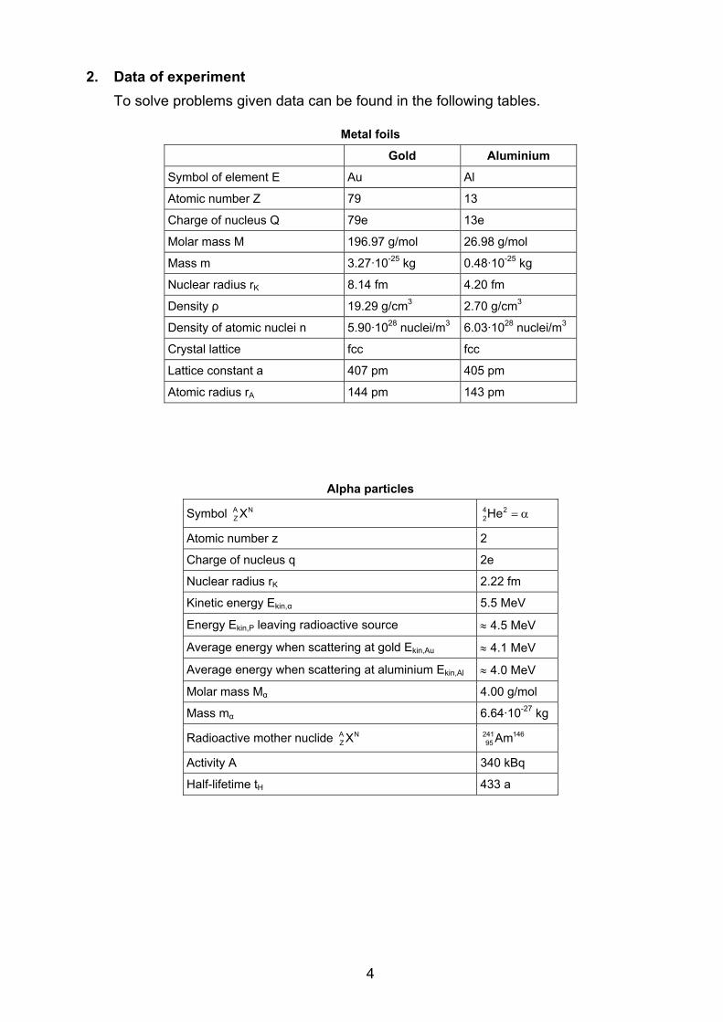
2. Data of experiment To solve problems given data can be found in the following tables.
Metal foils
Gold Aluminium
Symbol of element E Au Al
Atomic number Z 79 13
Charge of nucleus Q 79e 13e
Molar mass M 196.97 g/mol 26.98 g/mol
Mass m 3.27·10-25 kg 0.48·10-25 kg
Nuclear radius rK 8.14 fm 4.20 fm
Density ρ 19.29 g/cm3 2.70 g/cm3
Density of atomic nuclei n 5.90·1028 nuclei/m3 6.03·1028 nuclei/m3
Crystal lattice fcc fcc
Lattice constant a 407 pm 405 pm
Atomic radius rA 144 pm 143 pm
Alpha particles
Symbol A NZ X 4 2
2He = α
Atomic number z 2
Charge of nucleus q 2e
Nuclear radius rK 2.22 fm
Kinetic energy Ekin,α 5.5 MeV
Energy Ekin,P leaving radioactive source ≈ 4.5 MeV
Average energy when scattering at gold Ekin,Au ≈ 4.1 MeV
Average energy when scattering at aluminium Ekin,Al ≈ 4.0 MeV
Molar mass Mα 4.00 g/mol
Mass mα 6.64·10-27 kg
Radioactive mother nuclide A NZ X 241 146
95 Am
Activity A 340 kBq
Half-lifetime tH 433 a
4
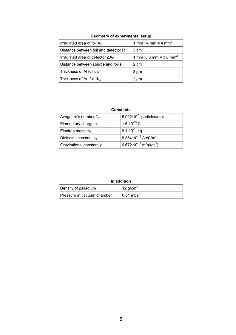
Geometry of experimental setup
Irradiated area of foil AF 1 mm · 4 mm = 4 mm2
Distance between foil and detector R 3 cm
Irradiated area of detector ΔAD 1 mm· 3.8 mm = 3.8 mm2
Distance between source and foil s 2 cm
Thickness of Al foil dAl 8 μm
Thickness of Au foil dAu 2 μm
Constants
Avogadro’s number NA 6.022·1023 particles/mol
Elementary charge e 1.6·10-19 C
Electron mass me 9.1·10-31 kg
Dielectric constant ε0 8.854·10-12 As/(Vm)
Gravitational constant γ 6.672·10-11 m3/(kgs2)
In addition
Density of palladium 12 g/cm3
Pressure in vacuum chamber 0.01 mbar
5

I. Problems about theory
1. Single particle scattering within Rutherford atomic model a) Calculate the forces between an alpha particle and an atom (Au, Al) of the metal foil
at a distance of 20 fm between the two centres and at minimum distance. Which qualitative statements based on the results can be made?
b) The relation between scattering angle ϑ and collision parameter b is given by: 2
o kin
zZeb co8 E 2
t( )ϑ=πε
Determine ϑ(b). Check the correctness of the new relation by a dimension analysis and in case of limiting cases.
Graph ϑ(b) in a suited coordinate system for the deflection of alpha particles by Au nucleus and by Al nucleus and explain differences.
Why is it impossible to check experimentally this relation ϑ(b)?
c) Fig. 1 shows the result of a simulation of scattering of alpha particles by the Coulomb force only at an Au nucleus.
Is this simulation correct? How can one recognize the fact
that less alpha particles are scattered at larger scattering angles?
d) By means of a modelling system (e.g. VII.9.) one can graph the trajectory of alpha particles.
Fig. 1: Simulation of scattering of alpha particles at an Au nucleus. Establish the necessary graphi-
cal model and check if the simu-lation is correct.
Formulate justified relations with respect to the size of the scattering angle and check their correctness within the model.
Imagine, the alpha particle is flying along the x-axis centrally against an Au nucleus positioned at x = 0: Display qualitatively the Coulomb force as a function of time FC(t) and of the kine-matic values x(t), vx(t) and ax(t). Check your predictions within the model.
Show by calculation that the incoming velocity and outgoing velocity of an alpha particle are the same. Extend your graphical model such that the validity of the en-ergy conservation law during the motion of the alpha particle can be shown.
6

2. Multi-particle scattering within Rutherford’s atomic model The Rutherford scattering formula is defining the amount of alpha particles ΔND/N, which are scattered by a metal foil under an angle ϑ and monitored by a detector area ΔAD:
( )22
DD2
4o kin
N nd zZe 1 AN 4R 8 E sin ( )
2
⎛ ⎞Δϑ = Δ⎜ ⎟ ϑπε⎝ ⎠
a) Explain qualitatively/semi-quantitatively the dependence of scattered particles ΔND/N on the different parameters/values.
Fig. 2: Exposure of traces of scat-tered particles on photographic foil
(from VII.6.).
b) Explain the rotational symmetry of the exposure of traces (Fig. 2). What are the qualitative interrelations between the Rutherford scattering formula and this expo-
sure? Discuss the limes D0
NlimNϑ→
Δ .
c) Perform a dimensional analysis of the Rutherford scattering formula. Simplify this function in the case of ΔND/N(180°) and describe the form of the graph of ΔND/N(ϑ). Display the graph ΔND/N(ϑ) for the scattering of alpha particles by a gold foil.
d) How many alpha particles of 109 incoming particles are scattered backward? How much time do we need in measurements to detect 10 backward scattered particles?
e) Graph the amount of scattered alpha particles, scattered up to a certain angle ϑ or scattered above a certain angle ϑ (sum function of distribution function). Determine the sum function analytically or by a computer algebra system. Formulate a state-ment which describes the scattering of alpha particles.
Hint: 3 2cosx 1dxsin x sin x
=∫ .
3. Model assumption to derive Rutherford’s scattering formula a) Term and justify the assumptions in the model to derive Rutherford’s scattering for-
mula (download text from RCL-website, Theory, 5.). Which of these assumptions go into which steps in the derivation (quote number of formula)?
b) The validity of which assumption could be checked varying the thickness d of metal foil in the Rutherford experiment?
c) Derive an expression for the relative energy loss ΔEkin/Ekin of a colliding particle 1 (mass m1, velocity v1) at a central, elastic collision with a second particle 2 at rest (mass m2, velocity v2 = 0). Discuss mathematically and physically this expression ΔEkin/Ekin as a function of mass ratio k = m1/m2. Apply this result to the scattering of alpha particles by a gold foil.
7

4. Estimation of the radius of atomic nuclei a) In which case is the distance to the Au nu-
cleus minimal for a scattered alpha particle? Derive an expression for the smallest dis-tance rmin between both centres (alpha parti-cle and atomic nucleus). How big is rmin in case of gold? Can one make a statement about the size of a gold nucleus?
b) What is the meaning of the broken line near 25 - 30 MeV in Fig. 3? How can one explain the deviation of experimental values and Rutherford’s scattering formula? In which di-rection must one shift the energy value Ekin,K at which one registers the deviation, if one is increasing the scattering angle ϑ?
c) The minimal distance between alpha particle and atomic nucleus is given by
minpot min
kin,P
brE (r )
1E
=
−
.
Check the validity of this expression in the special case of a). Estimate the upper value of nuclear radius of gold with the information of Fig. 3 in b).
Fig. 3: Theoretically predicted (bro-ken line) and experimentally found
attering rate (circles) for gold anscattering angle 60°.
sc d
d) The nuclear potential of atomic nuclei can be modelled with good approximation by the Saxon-Woods potential (V0 = 50 MeV, a = 0.5 fm and = ⋅ 3
Kr 1.4 fm A ):
K
0r r
a
VV(r)1 e
−= −+
.
What is the meaning of the parameters V0, rK and a? Display graphically the total potential of an alpha particle in the field of a gold atom. Investigate the influence of nuclear forces on the number of scattered alpha particles at angle ϑ by a modelling software program.
5. Particle scattering within Dalton’s atomic model a) Derive a relation between collision parameter b and scattering angle ϑ for alpha
particles under the assumption, that the scattering objects are atoms like hard spheres with radius rK. Display this deflection function ϑ(b) for gold atoms graphi-cally and compare this one with the one of Rutherford.
b) Analogous to Rutherford’s scattering formula derive a scattering formula within Dal-ton’s model. Determine the amount of scattered alpha particles by gold atoms and compare this result with experimental data. Discuss the range of applicability of the scattering formula in the Dalton model.
8

6. Particle scattering within Thomson’s atomic model a) Look up (VII.4. or VII.11.), which experiments with cathode rays the physicist
Philipp Lenard performed around 1894. Part of these results already showed, that the Thomson atomic model only partially describes the structure of atoms.
b) The size of deflection of alpha particles by gold atoms within Thomson’s model can be determined differently:
Determine the deflection angle under the simplifying assumption, that the maximum possible deflection force is acting on an alpha particle over a distance of four atomic radii and is constant in that range.
According to VII.1. the average scattering angle is 2
0 A kin,P
Ze32 r E
ϑ =ε
:
Try to understand the derivation of this formula. Insert actual parameters and de-termine the angle.
Investigate the deflection in Thomson’s model by a means of a modelling software.
c) Which assumptions in Thomson’s atomic model are able to explain the experimen-tal data for large scattering angles? The distribution of scattering angles after the scattering of N alpha particles by m atomic layers is given by a Gauss distribution (VII.1., S. 63):
2
D,T 0N ( ) N e⎛ ⎞ϑ⎜ ⎟−⎜ ⎟ϑ⎝ ⎠Δ ϑ = with mϑ = ⋅ϑ .
Compare this distribution in case of N0(200 s) = 2100 with the distribution in Ruther-ford’s atomic model (see III.4).
7. Structure of metal foils The crystal structure of the two metals, gold and alumin-ium, are face-centred cubic (fcc). Fig. 4 shows the ele-mentary cell:
a) Calculate the lattice constant a from macroscopic quanti-ties such as density. What is the amount of volume of the metal foil filled by atoms or nuclei? What is the ratio of atomic radius to nuclear radius? Fig. 4: Elementary cell
of a cubic face-centred lattice. b) Estimate qualitatively the atomic radii rA for Au and Al
and compare with literature values. Determine the num-ber of atomic layers of the metal foils with thickness d.
c) Determine the density n of atomic nuclei (i.e. number of nuclei per volume). Is this density a value averaged over atomic positions? How big is the area density nF (i.e. number of nuclei per area) when looking through the metal foil. What is the average distance e between nuclei in that case?
9

8. Motion of electrons within Rutherford atomic model a) Why does it make sense in a first approach to assume a circular / spherical motion
of electrons around an atomic nucleus?
b) Express the velocity v and the time interval for one orbit T of electrons by natural constants and the trajectory radius r. Calculate v, T and Coulomb force FC in case of r = 50 pm.
c) Calculate the kinetic energy Ekin, the potential energy Epot and the total energy Etot of an electron as a function of trajectory radius r. What is the relation between Ekin and Epot? How is the total energy Etot changing if we increase the distance to the atomic nucleus? Display the functions Ekin(r), Epot(r) and Etot(r) in case of Au atoms in a coordinate system. Which phenomena cannot be explained in that picture of an electron shell around a nucleus?
d) Due to classical electrodynamics accelerated charges radiate electromagnetic waves. What are the consequences in our case?
10

II. Problems about experimental setup
1. Experimental setup of the RCL “Rutherford’s Scattering Experiment” Fig. 5 shows the total setup (left part, without vacuum pump), the webcam picture (right part, up) and the control field (right part, down).
Fig. 5: Picture of total setup, webcam picture and contol panel of RCL.
a) Fill in a table with three columns: number, assignment and function.
2. Radioactive source for Rutherford’s scattering experiment In principle two radioactive sources are possible for Rutherford experiment (selec-tion from manufacturer):
Nuclide Am-241 Ra-226
Activity A 340 kBq 3.3 kBq
Diameter of source 2.5 mm 3 mm
Covering 2 µm rare metal foil 2 µm rare metal foil
Energy level scheme
a) What is the more suited radioactive source for the Rutherford experiment and justify your choice.
b) Conversion electrons are produced during the decay of Am-241: explain the proc-ess of production and what is the difference to the β-radiation? Do these conversion electrons influence the measurements of the Rutherford experiment?
11
c) The activity of Am-241 sample will decrease with time. Is this relevant for the ex-periment?
d) What are the major rules when experimenting with radioactive sources?
e) What is the velocity of alpha particles in ideal vacuum when striking the metal foil? Which acceleration voltage UB must be applied to the alpha particles to reach the same velocities?
3. Detector for alpha particles a) Explain the working principle of a semiconducting detector.
b) What are the advantages of such a detector in comparison with an ionisation cham-ber?
12

III. Problems about measurements and data analysis
1. Difficulties performing Rutherford’s scattering experiment at school a) Derive an expression to determine the total number N of scattered alpha particles
by the metal foil area AF. How big is N for a measuring time interval of t = 300 s?
b) What is the experimental result for the angular dependence of the number ΔND of scattered alpha particles with gold as metal foil and 300 s measuring time? Which percentage of these alpha particles will be scattered at angle 10°, 20° and 30°?
c) What is the maximum range of scattering angles in that RCL experiment? Suppose that alpha particles are scattered in an ideal scattering geometry with a statistical error f (f = 20 % or 50 %) and 300 s acquisition time? Reflect this result with respect to the interaction of theory and experiment in physics in general.
d) What is the proper interval of two scattering angles measuring ΔND(ϑ)? Specify a series of scattering angles with the following conditions: t ≤ 300 s, f ≤ 50 %, ttotal ≤ 20 min to collect a sufficient amount of data for further analysis.
e) What are possible changes in the experimental set-up and possible actions per-forming these measurements with the aim to increase the number ΔND of scattered alpha particles? Which constraints exist for which suitable actions from above? Which actions are best suited to improve the expected results? Look up the original publication VII.3. for that reason.
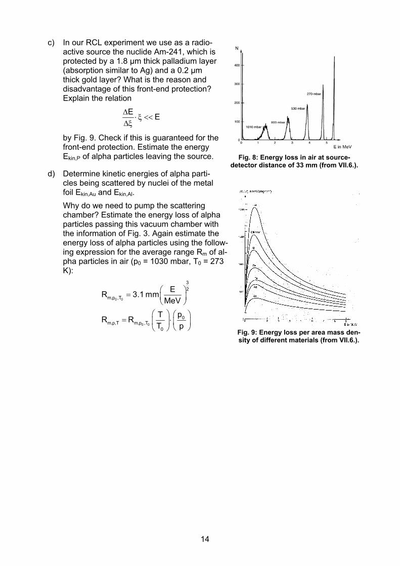
2. Absorption of alpha radiation a) Fig. 6 - 8 show the experimental results for the absorption of 5,5 MeV alpha parti-
cles from a radioactive source Am-241 by different matter: Which general state-ments about this absorption can be made? Explain these interrelations qualitatively.
Fig.6: Energy loss in Al foils of different thickness (from VII.6.).
Fig. 7: Energy loss in foils (Au, Al) of same thickness (from VII.6.).
b) What is the relation between thickness d of a homogenous foil and its mass with re-spect to its mass density per area ξ = m/AF? Determine ξ for the case of gold and aluminium foil. Why one uses more ξ instead of d to characterize thin foils?
13
c) In our RCL experiment we use as a radio-active source the nuclide Am-241, which is protected by a 1.8 μm thick palladium layer (absorption similar to Ag) and a 0.2 μm thick gold layer? What is the reason and disadvantage of this front-end protection? Explain the relation
E EΔ⋅ ξ <<
Δξ
by Fig. 9. Check if this is guaranteed for the front-end protection. Estimate the energy Ekin,P of alpha particles leaving the source. Fig. 8: Energy loss in air at source-
detector distance of 33 mm (from VII.6.).d) Determine kinetic energies of alpha parti-
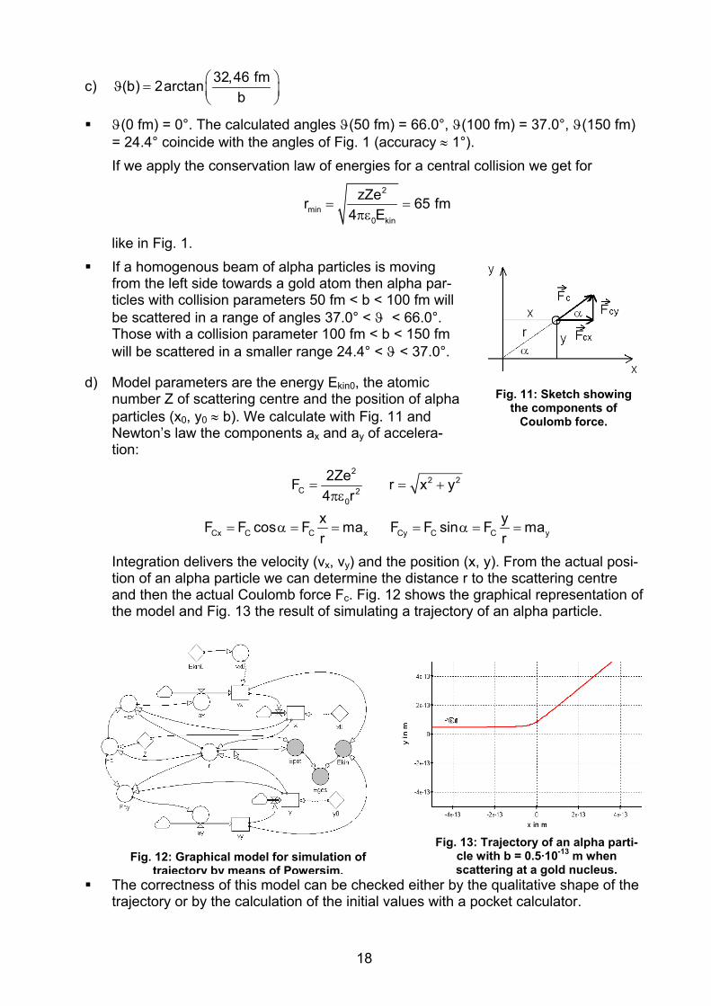
cles being scattered by nuclei of the metal foil Ekin,Au and Ekin,Al. Why do we need to pump the scattering chamber? Estimate the energy loss of alpha particles passing this vacuum chamber with the information of Fig. 3. Again estimate the energy loss of alpha particles using the follow-ing expression for the average range Rm of al-pha particles in air (p0 = 1030 mbar, T0 = 273 K):
⎛ ⎞= ⎜ ⎟⎝ ⎠
⎛ ⎞ ⎛ ⎞= ⋅⎜ ⎟ ⎜ ⎟
⎝ ⎠⎝ ⎠
0 0
0 0
32
m,p ,T
0m,p,T m,p ,T
0
ER 3.1 mmMeV
pTR RT p
Fig. 9: Energy loss per area mass den-sity of different materials (from VII.6.).
14

3. Impact of detector area on scattering rate a) Which range in angle picks up the detector positioned at angle ϑ when monitoring
the scattering rate? Consider which number registers the detector using the behav-iour of ΔND(ϑ). Do we register for the number of scattered particles ΔND a too big or too small value? Control your suppositions for one scattering angle in case of gold and 300 s measuring time interval.
Hint: 4 2x 2 x x2
sin dx cot 2 sin2 3 2
− −⎡ ⎤⎛ ⎞⎜ ⎟
⎛ ⎞ ⎛ ⎞= − ⋅ +⎜ ⎟ ⎜ ⎟ ⎢ ⎥⎝ ⎠ ⎝ ⎠ ⎝ ⎠⎣ ⎦∫
b) Compare in a suited coordinate system the number of scattered alpha particles ΔND(ϑ) according to Rutherford’s formula in case of gold and 300 s measuring time with the number of alpha particles registered by the detector. Determine the relative error f(ϑ) due to the finite detector area and discuss this result.
c) How can we use this result of b) to handle the small values ΔND for large scattering angles?
4. Data analysis in case of Au foil We measured the following scattering events for the gold foil by this RCL setup (download these data from the RCL-website, Material, 2.). ϑ in ° -50 -48 -45 -42 -39 -36 -33 -30 -29 -28 -27 -26 -25 -24 -23 t in s 78925 67440 53070 40920 30670 22497 16170 11105 9750 8400 7405 6410 5480 4710 3940 ΔND 51 51 47 57 52 48 51 52 48 45 38 47 50 55 51
ϑ in ° -22 -21 -20 -19 -18 -17 -16 -15 -14 -13 -12 -11 -10 -9 -8 t in s 3310 2745 2270 1850 1500 1192 930 718 550 410 300 200 200 200 200 ΔND 49 47 56 58 53 55 34 53 63 62 70 78 99 170 262
ϑ in ° -7 -6 -5 -4 -3 -2 -1 0 1 2 3 4 5 6 7 t in s 200 200 200 200 200 200 200 200 200 200 200 200 200 200 200 ΔND 369 602 1054 1267 1503 1902 2130 2095 2046 1778 1530 1187 827 589 487
ϑ in ° 8 9 10 11 12 13 14 15 16 17 18 19 20 21 22 t in s 200 200 200 200 300 410 550 718 930 1192 1500 1850 2270 2745 3310 ΔND 267 169 100 61 70 53 55 57 50 50 46 50 59 42 39
ϑ in ° 23 24 25 26 27 28 29 30 33 36 39 42 45 48 50 t in s 3940 4710 5480 6410 7405 8400 9750 11105 16170 22497 30670 40920 53070 67440 78925ΔND 42 51 46 43 52 43 56 39 41 45 44 45 43 50 47
a) Why did we increase the measuring time interval for larger scattering angles? How long would had been the measuring time interval, to determine the back scattered (ϑ = 180°) alpha particles with an accuracy of 15%?
b) Display graphically the function ΔND(ϑ) and determine the offset of scattering angle (i.e. shift in angle between ϑ = 0° and maximum scattering rate).
15

c) What are the possibilities to investigate a series of data, if there is a functional de-pendence? Check how good the Rutherford formula is describing these measured data. Determine the lower limit of validity for the scattering angle in Rutherford’s for-mula (i.e. angle at which experimental data and theoretical function deviate). De-termine the atomic number Z for gold from these data.
d) Suppose the Rutherford scattering formula is not known: Try to fit the measured data ΔND(ϑ) by a suited function. Control your assumption and justify your choice.
5. Investigation of further dependencies of scattering rate The following table (from VII.2.) presents measured values of registered alpha par-ticles ΔND as a function of further technical parameters such as thickness d of foil, kinetic energy Ekin of alpha particles and kind of foil Z:
ξ in mg/cm2 0.29 0.42 0.57 0.85 1.12 1.94 d in μm
ΔND/1000 s 168 283 420 504 780 1236
ϑ = 17.5° Z = 79
Ekin = 5.48 MeV
Ekin,α in MeV 4.82 4.90 5.00 5.04 5.08 5.17 ΔND/1000 s 10023 8734 7670 7631 7204 6427
ϑ = 17.5° Z = 79
Z 13 (Al) 28 (Ni) 29 (Cu) 47 (Ag) 79 (Au)
ΔND/(1000s⋅nd) in m-2 2.05⋅107 9.30⋅107 1.50⋅108 2.20⋅108 1.05⋅109 ϑ = 17.5°
Ekin = 5.48 MeV
a) Which dependencies of ΔND on these parameters do we expect due to Rutherford’s
scattering formula?
b) Rewrite the density ξ into thickness d and investigate ΔND(d) according to your hy-pothesis. Justify this dependence physically.
c) Investigate ΔND(Ekin) according to your hypothesis. How can we change the kinetic energy Ekin of alpha particles and how can we determine Ekin?
d) Why are the data for the scattering rate versus atomic number Z presented differ-ently like before (ΔND/1000s)? Investigate also this measuring values according to your hypothesis.
16

IV. Solutions to problems I
1. Single particle scattering within Rutherford’s atomic model a) The Coulomb force FC, the gravitational force FG (and the here disregarded nuclear
force) are acting between both particles:
1 2C 2
0
Q QF4 r
=πε
1 2G 2
m mFr
= γ .
The minimum distance between both particles are rmin,Au = 8.14 fm + 2.22 fm = 10.36 fm, rmin,Al = 4.20 fm + 2.22 fm = 6.42 fm, respectively.
Au (Z = 79) Al (Z = 13)
r = 20 fm FC = 90.88 N FG = 3.62·10-34 N
FC = 14.95 N FG = 4.98·10-35 N
r = rmin FC = 338.71 N
FG = 1.35·10-33 N FC = 145.14 N
FG = 4.84·10-34 N
• FG can be neglected in comparison with FC.
• These microscopic electrostatic forces are of the same size like forces in every-day. We observe therefore large accelerations due to small masses of atoms.
• FG as well as FC are increasing with atomic number Z, because the mass of nu-clei is increasing with Z.
b)
2
o kin
zZe(b) 2arctan8 E b
⎛ ⎞ϑ = ⎜ ⎟πε⎝ ⎠
, 2 2
o kin
zZe (As) Vm 18 E b AsVAsm⎡ ⎤
= =⎢ ⎥πε⎣ ⎦
Back scattering: o(0) 2arctan( ) 2 90 180ϑ = ∞ = ⋅ = ° No deflection: ( ) 2arctan(0) 2 0 0ϑ ∞ = = ⋅ ° = °
⎛ ⎞ϑ = ⋅⎜ ⎟⎝ ⎠
ZZ(b) 2arctan 0.31 fmb
. Since
ZAu > ZAl, a larger Coulomb force is acting on alpha particles at any time of the scattering trajectory in case of Au nucleus instead of Al nucleus. The scattering angle is larger in case of Au (red curve) instead of Al (blue curve) at the same collision parameters (Fig. 10).
One is not able to proof this experi-mentally, because there is no way to isolate gold atoms and shoot par-ticles on them in a distance of fem-tometer.
Fig. 10: Representation of scattering angle as a function of collision parameter for gold (Z = 79,
red) and for aluminium (Z = 13, blue). The position of the respective nucleus is shown in the center.
17
c) 32,46 fm(b) 2arctanb
⎛ ⎞ϑ = ⎜ ⎟⎝ ⎠
ϑ(0 fm) = 0°. The calculated angles ϑ(50 fm) = 66.0°, ϑ(100 fm) = 37.0°, ϑ(150 fm) = 24.4° coincide with the angles of Fig. 1 (accuracy ≈ 1°). If we apply the conservation law of energies for a central collision we get for
2
min0 kin
zZer 64 E
= =πε
5 fm
like in Fig. 1. If a homogenous beam of alpha particles is moving
from the left side towards a gold atom then alpha par-ticles with collision parameters 50 fm < b < 100 fm will be scattered in a range of angles 37.0° < ϑ < 66.0°. Those with a collision parameter 100 fm < b < 150 fm will be scattered in a smaller range 24.4° < ϑ < 37.0°.
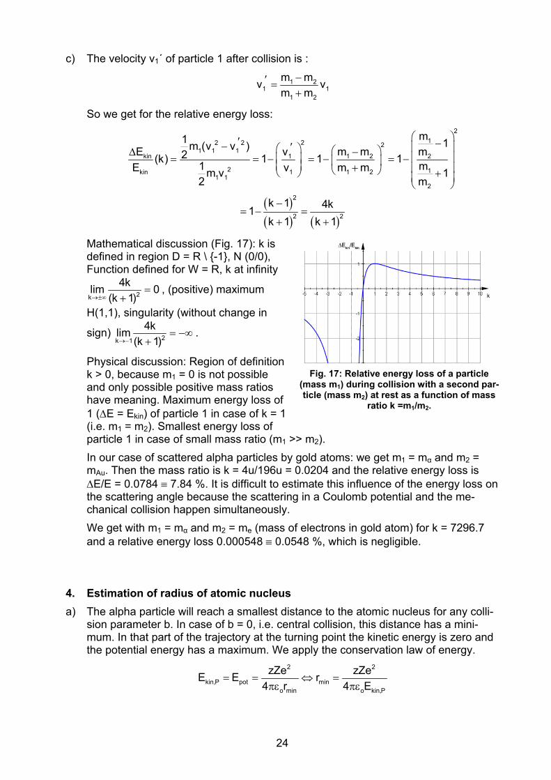
d) Model parameters are the energy Ekin0, the atomic number Z of scattering centre and the position of alpha particles (x0, y0 ≈ b). We calculate with Fig. 11 and Newton’s law the components ax and ay of accelera-tion:
Fig. 11: Sketch showing the components of
Coulomb force.
22 2
C 20
Cx C C x Cy C C y
2ZeF r x y4 rx yF F cos F ma F F sin F mar r
= = +πε
= α = = = α = =
Integration delivers the velocity (vx, vy) and the position (x, y). From the actual posi-tion of an alpha particle we can determine the distance r to the scattering centre and then the actual Coulomb force Fc. Fig. 12 shows the graphical representation of the model and Fig. 13 the result of simulating a trajectory of an alpha particle.
The correctness of this model can be checked either by the qualitative shape of the trajectory or by the calculation of the initial values with a pocket calculator.
Fig. 13: Trajectory of an alpha parti-cle with b = 0.5·10-13 m when scattering at a gold nucleus.
Fig. 12: Graphical model for simulation of trajectory by means of Powersim.
18

The scattering angle ϑ of alpha
particles is larger, Argumentation
if the collision parameter b is smaller.
The alpha particle is passing the collision centre at smaller distance and is experiencing a larger Coulomb force.
if the velocity v0 is smaller. The Coulomb force is acting on the particle during a longer time interval.
if the mass m of alpha particle is smaller. The alpha particle has a smaller moment of inertia.
if the atomic number Z of scatter-ing nucleus is larger. The Coulomb force is larger acting on the alpha particle.
These statements can be checked by the model varying respective values or pa-rameters.
Table containing qualitative considerations and graphs (tu time at turning point)
• Fcx < 0, because direction of force al-ways opposite to x direction.
• Fcx| for 0 < t < tu increasing and for t > tu decreasing, since FC ~ 1/r2.
• Fcx symmetric at t = tu, because the same trajectory is followed in opposite direc-tion.
• shape of graph like Fcx, because ax ~ Fcx.
• vx > 0 for 0 < t < tu, because motion in x-direction, vx < 0 for t > tu, because motion in opposite x-direction.
• graph vx has parity symmetry at (tu,0).
• x < 0 for all t, because incoming and out coming motion on negative x-axis.
• |x| for 0 < t < tu increasing and for t > tu de-creasing, because incoming/outgoing mo-tion.
• graph x symmetric at t = tu.
At infinite distance of the scattering atom the potential energy of the alpha particle is constant and can be chosen freely, e.g. Epot(∞) = 0. If we call v0 the incoming veloc-ity and v∞ the outgoing velocity then – according to conservation law of energy – we get:
2 20 0
1 1mv 0 mv 0 v v2 2 ∞ ∞+ = + ⇒ =
19

The model must be extended by some values (see grey shaded circles in Fig. 12):
22
kin pot0
2 2tot kin pot x y
1 2E mv E2 4
E E E v v v
= =πε
= + = + 2
Zer
Fig. 14 shows that the law of energy conservation is fulfilled at every time t.
Fig. 14: Kinetic (green), potential (red) and total energy (blue) during scattering process.
20

2. Multiple scattering within Rutherford atomic model a) The next table contains dependencies of respective parameters keeping all other
parameters constant.
Dependence Explanation
D4
1N ~sin
2
Δϑ⎛ ⎞
⎜ ⎟⎝ ⎠
• The dependence of ΔND on scattering angle ϑ is generated by the r-dependence of the Coulomb force. The quantitative relation can be un-derstood only reading the section “Derivation of scattering formula”.
2DN ~ ZΔ
• The dependence of ΔND on element number Z is generated by the Z-dependence of the Coulomb force.
• Since b ~ Z and Δb ~ Z we get for the scattering area of alpha particles with collision parameter b that ΔAb = 2πbΔb ~ Z2.
DN ~ d N ~ nΔ Δ D
• If we increase the thickness of metal foil d or the density n of atomic nuclei also ΔND/N will increase, because we increase the number of scattering centres.
D 2kin
1N ~E
Δ • An incoming alpha particle with larger kinetic energy will reach closer
an atomic nucleus. Because the Coulomb force closer to an atomic nu-cleus is increasing the scattered alpha particles will be deflected stronger.
D DN ~ AΔ Δ • If we increase the detector ΔAD more alpha particles will be registered supposed the scattering rate (due to angle interval) is not changed.
D 2
1N ~R
Δ • If we increase the distance R between metal foil and detector the scat-
tered alpha particles will be distributed on a larger surface sphere, ΔND will decrease.
b) Alpha particles with one and the same collision parameter will be scattered by gold atoms always in the same scattering angle because of the radially acting Coulomb force.
Picture/graph Formula
Distribution is rotational-symmetric One given scattering angle ϑ is sufficient to describe the distribution. The distribution ΔND is symmetric to ϑ = 0 because the exponent of sin4(ϑ/2) is even.
Scattering rate is decreasing with in-creasing scattering angle
ϑ larger → sin(ϑ/2) larger → sin4(ϑ/2) larger → 1/ sin4(ϑ/2) smaller
Scattering rate is quickly decreasing (for ϑ > 10° almost no scattered par-ticles)
Fourth power of sin4(ϑ/2)
Given D0
NlimNϑ→
Δ→ ∞ . The reason for this behaviour is lying in the model assumption:
which means, that one alpha particle is interacting only with one scattering centre and the interaction with other scattering centres is neglected. Consequently, the model allows collision parameter b = ∞ for scattering angle ϑ = 0. The range of col-lision parameters b is limited, about half of the atomic radius. Experimentally we get
D D0
N Nlim (0 )N Nϑ→
Δ Δ= ° < ∞ ,
because only a finite number of alpha particles will hit the metal foil.
21

c) The dimension analysis must deliver 1 for the scattering rate:
2 22 22
D2 3 24o kin
nd zZe 1 m (As) VmA m 14R 8 E m m AsVAssin ( )
2
⎡ ⎤⎢ ⎥⎛ ⎞ ⎛ ⎞
Δ = =⎜ ⎟⎢ ⎥ ⎜ ⎟ϑπε ⎝ ⎠⎝ ⎠⎢ ⎥⎣ ⎦
D22D D
D24o kin
N (180 )N nd zZe N NN(180 ) A ( ) (180 )cosec( )N 4R 8 E N Nsin ( )
2
Δ°⎛ ⎞Δ Δ Δ
° = Δ ⇒ ϑ = = °⎜ ⎟ ϑπε⎝ ⎠D
2ϑ
The scattering rate will be divided by a larger value with increasing scattering angle. The graph is monotonically decreasing for 0 < ϑ ≤ 180°. If we insert all technical/physical data we get (Fig. 15):
−Δ ⋅ϑ =
ϑ
7D
4
N 1.5 10( )N sin ( )
2
.
d) According to the scattering formula of part b) we get ΔND = 150 back scattered particles (ϑ = 180°) if the beam of alpha particles contains N = 109.
D D D DD
D
N N N N NNN N (180 ) (180 ) A (180 ) t NN t t N N
Fig. 15: Scattering rate as a function of scattering angle.
D
A (180 )N
Δ Δ Δ Δ ΔΔ = ° ⇔ = ° = ° ⇒ =
Δ°
If the activity A = 340 kBq and ΔND = 10 the measuring time interval is t = 196 s ~ 3 min.
e) According to theory the number dN of scattered particles in a range of angle ϑ and ϑ + dϑ is
22
3o kin
22
3 o kin
cos( )zZe 2dN Nnd d8 E sin ( )
2
cos( ) zZe2Nk d with k=nd8 Esin ( )
2
ϑ⎛ ⎞
= π ϑ⎜ ⎟ ϑπε⎝ ⎠
ϑ⎛ ⎞
= ϑ π⎜ ⎟ϑ πε⎝ ⎠
Since dN diverges for ϑ → 0, one can only determine the number of scattered particles in a range of angle ϑ < ϑ´ ≤ π - the sum function.
Fig. 16: Sum function of distribution nction of scattering rate as a functio
of scattering angle for gold. fu n
22

N( )´ 2 2
3N( )
2 2
´cos( )1 1 ´2dN k d ´ [N( ) N( )] k sin ( ) k(1 sin ( ))´N N 2sin ( )2
N( ) N( )1 k k sin ( ) 1 k[1 sin ( )]N 2 N 2
ππ π− −
ϑϑ ϑ
− −
ϑ
2ϑ ϑ⎡ ⎤= ϑ ⇔ π − ϑ = − = − −⎢ ⎥ϑ ⎣ ⎦
ϑ ϑ ϑ ϑ⇔ − = − + ⇔ = + −
∫ ∫
The sum function is displayed in Fig. 16. If we insert all given numbers/values (k = 2.22·10-4) more than 95 % of the alpha particles will be scattered at angles smaller than 10 %. Only less than 5 % of alpha particles are scattered at angles larger than 10°.
3. Model assumptions for the derivation of Rutherford’s scattering formula a)
Assumption Justification No. of formula
Only the Coulomb force is acting on alpha particles
• Gravitational forces can be neglected (see problem I.1a). • Nuclear forces are essential only at small collision parame-
ter (see I.4). 1
Alpha particles as well as atomic nuclei are consid-ered fictive points
• Nuclear dimensions were not known in those times. • Dimensions of alpha particles and atomic nuclei do not in-
fluence the trajectory of alpha particles, unless rmin > rK,α + rK,A.
-
Each alpha particle will be scattered only by one atomic nucleus (single particle scattering)
• Multiple scattering can be neglected if 1dn
<<σ
, with σ total
cross section. • With b(ϑ=10°) = 0.317 pm and σ = πb2 we get for gold d <<
54 μm, but the gold foil is d ~ 2 μm.
7
Beam of alpha particles is homogenous
• Technically realized by a point-like radioactive source. • Irradiated area of metal foil AF << 4πs2 (with s-distance
source to foil). 7
Beam of particles is con-stant in time
• Justified due to the half-lifetime of Am-241 tH = 433 years (see II.2c). -
Motion is not relativistic • vα/c ~ 1/10, respectively m/m0 ~ 1.001. 3, 5
No energy losses of al-pha particles at collision
• Because mα/mAu ~ 1/50, we consider the collision with tar-get nucleus is elastic (see I.3c).
• Because mα/me ~ 7300, elastic collision also with electrons (see I.3c).
• No ionisation of target atoms.
5
Alpha particles are scat-tered only by atomic nu-clei
• Because mα/me ~ 7300, deflection by electrons can be ne-glected. 1, 7
b) If we duplicate the thickness d of metal foil then we also duplicate the scattering centers, supposed single particle scattering the number of scattered alpha particles ΔND (ϑ) will be duplicated too (compare I.2a).
23
c) The velocity v1´ of particle 1 after collision is :
1 21 1
1 2
m mv vm m
−′ =+
So we get for the relative energy loss:
( )( ) ( )
2122 2 2
1 1 1kin 1 1 2 2
2 1kin 1 1 21 1
2
2
2 2
m1 1m (v v )E v m m2(k) 1 1 11 mE v m mm v 12 m
k 1 4k1k 1 k 1
⎛ ⎞′ −− ′ ⎜ ⎟⎛ ⎞ ⎛ ⎞Δ − ⎜ ⎟⎜ ⎟= = − = − = −⎜ ⎟⎜ ⎟ + ⎜ ⎟⎝ ⎠⎝ ⎠ +⎜ ⎟⎝ ⎠
−= − =
+ +
m
Mathematical discussion (Fig. 17): k is defined in region D = R \ {-1}, N (0/0), Function defined for W = R, k at infinity
2k
4klim 0(k 1)→±∞
=+
, (positive) maximum
H(1,1), singularity (without change in
sign) 2k 1
4klim(k 1)→−
= −∞+
.
Physical discussion: Region of definition k > 0, because m1 = 0 is not possible and only possible positive mass ratios have meaning. Maximum energy loss of 1 (ΔE = Ekin) of particle 1 in case of k = 1 (i.e. m1 = m2). Smallest energy loss of particle 1 in case of small mass ratio (m1 >> m2). In our case of scattered alpha particles by gold atoms: we get m1 = mα and m2 = mAu. Then the mass ratio is k = 4u/196u = 0.0204 and the relative energy loss is ΔE/E = 0.0784 ≡ 7.84 %. It is difficult to estimate this influence of the energy loss on the scattering angle because the scattering in a Coulomb potential and the me-chanical collision happen simultaneously. We get with m1 = mα and m2 = me (mass of electrons in gold atom) for k = 7296.7 and a relative energy loss 0.000548 ≡ 0.0548 %, which is negligible.
Fig. 17: Relative energy loss of a particle ass m1) during collision with a second par
icle (mass m2) at rest as a function of massratio k =m1/m2.
(m -t
4. Estimation of radius of atomic nucleus a) The alpha particle will reach a smallest distance to the atomic nucleus for any colli-
sion parameter b. In case of b = 0, i.e. central collision, this distance has a mini-mum. In that part of the trajectory at the turning point the kinetic energy is zero and the potential energy has a maximum. We apply the conservation law of energy.
= = ⇔ =πε πε
2 2
kin,P pot mino min o kin,P
zZe zZeE E r4 r 4 E
24

In our case – alpha particle on gold atom – we get rmin = 50.5 fm. This value for the nuclear radius is only an upper limit, because we do not know, if the alpha particle penetrates into a region of nuclear forces.
b) According to Rutherford’s scattering formula we get the following dependence
D 2kin
1E
cleus in a range, where the short range attractive nuclear forces are acting. There-fore, the resulting forces (repulsive Coulomb force, attractive nuclear forces) on thalpha particle will be smaller and less alpha particles will be registered at a fixed scattering angle e.g. ϑ = 60° as in the case where only Coulomb force is acting. increase in scattering angle means that we are considering alpha particles with smaller collision parameter b. These ones are coming closer to the nucleus, such that the de
N ~Δ . Alpha particles with high kinetic energy almost reach the atomic nu-
e
An
flection of alpha particles already starts at lower kinetic energies of alpha particles.
eter can
be derived from the deflection function (see RCL-website, Theory, 1.3):
c) For collision parameter b = 0 we get Epot(rmin) = Ekin,P since rmin ≠ 0. At Ekin,K = 28 MeV all energy considerations can be performed in Coulomb potential, because themeasured value is lying on Rutherford curve ΔND (ϑ). The collision param
2Au
o kin,K
zZ eb( ) cot( )8 E 2
ϑϑ =
πε.
ϑ = 60° we get b = 7.027 fm. The potential energy for the Coulomb interac-tion is And for
2
pot04 r r
zZe kE (r) = = .
To get rmin we have to solve a quadratic equation:
πε
min minmin kin,Kpot min
kin,K
2 2minmin min min
kin,K kin,K
2
2min
2
b kr r 1 br EE (r )
1E
kr kr b r r b 0E E
k kr b2E 2E
= ⇔ − =
−
⇔ − = ⇔ − − =
⎛ ⎞= ± +⎜ ⎟⎜ ⎟
get rAu ≤ 10 fm (from literature r = 8.14 fm).
nd
kin,K kin,K⎝ ⎠
The minus sign leads to a negative radius of gold nucleus. For the positive sign we get rmin = 12.17 fm. If we subtract the radius of alpha particles (rα = 2.2 fm) we
Au
d) V0 means the minimum of nuclear potential, rKmeans the width of the nuclear potential ameans the steepness of the transition be-
F -ig. 18: Shape of the attractive core potential (red) and of total potential of
gold nucleus (blue).
25
tween minimum and maximum of potential well (Fig. 18, red curve). The total potetial is given by the sum of Saxon-Woods potential and Coulomb potential, where thCoulomb potential is fitted to the minimum of Saxon-W
n-e
oods potential (Fig. 18, blue curve).
atomic model
get the deflection function for values b ≤ rK:
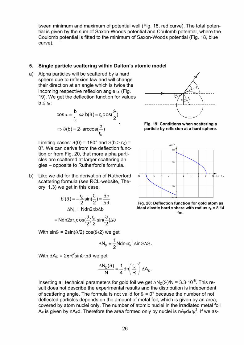
5. Single particle scattering within Dalton’sa) Alpha particles will be scattered by a hard
sphere due to reflexion law and will change their direction at an angle which is twice theincoming respective reflexion angle α (Fig. 19). We
KK
Kr
bcos b( ) r c os( )r 2
b(b) 2 arccos( )
ϑα = ⇔ ϑ =
⇔ ϑ = ⋅.
gles – opposite to Rutherford’s formula.
ebsite, The-ory, 1.3) we get in this case:
Limiting cases: ϑ(0) = 180° and ϑ(b ≥ rK) = 0°. We can derive from the deflection func-tion or from Fig. 20, that more alpha parti-cles are scattered at larger scattering an-
Fig. 19: Conditions when scattering a particle by reflexion at a hard sphere.
b) Like we did for the derivation of Rutherford scattering formula (see RCL-w
K
D
KK
r bb´( ) sin( )2 2
N Ndn2 b brNdn2 r cos( ) sin( )
2 2 2
ϑ Δϑ = − ≡
ΔϑΔ = π Δ
ϑ ϑ= π Δϑ
With sinϑ = 2sin(ϑ/2)·cos(ϑ/2) we get
Fig. 20: Deflection function for gold atom as ere ideal elastic hard sph with radius rk = 8.14 fm.
2D K
1N Ndn r sin2
Δ = π ϑΔϑ .
With ΔAD = 2πR2sinϑ·Δϑ we get 2
D KD
N ( ) r1 dn AΔ ϑ ⎛ ⎞N 4 R
= Δ⎜ ⎟ .
l AF is given by nAFd. Therefore the area formed only by nuclei is nAFdπrK
2. If we as-
⎝ ⎠
Inserting all technical parameters for gold foil we get ΔND(ϑ)/N = 3.3·10-8. This re-sult does not describe the experimental results and the distribution is independentof scattering angle. The formula is not valid for ϑ = 0° because the number of not deflected particles depends on the amount of metal foil, which is given by an area, covered by atom nuclei only. The number of atomic nuclei in the irradiated metal foi
26

sume that the areas of atomic nuclei do not overlap we get for this part of area ndπrK
2, in case of gold 2.45·10-5. The distribution function in this model is 2
KDD
2K
r1 dn A for 0N ( ) 4 RN
ndr for 0
⎧ ⎛ ⎞ Δ ϑ ≠Δ ⎪ ⎜ ⎟ϑ = ⎨ ⎝ ⎠⎪ ϑ =⎩
6. Single particle scattering within Thomson’s atomic model a) Accelerated electrons can leave the cathode ray tube through the Lenard-window
(3-5 μm thick Al foil stabilized by grid of tiny wires). A foil of 4 μm thickness consists out of 28000 atomic layers because the diameter of an Al atom is 143 μm. Only very few electrons can penetrate through this Al foil, since due to Thomson’s model all atoms consist completely out of matter.
b) The alpha particle is moving under the action of a constant electrostatic force, i.e.
with constant acceleration a on a parabolic trajectory: 2 2
20 2 2
0 o2 2 2
22 2 2
o A 0 o A kin,P
1 1 x F Zx(t) v t and y(t) at y(x) a a2 2 v m 2
Ze x Zey(x) x4 r m v 8 r E
A
er mα α
α
= = ⇒ = = =πε
= =πε πε
The respective scattering angle is the angle at which the particle leaves the electro-static field at the position x = 4rA. This angle can be determined as the slope of the trajectory at this position:
⎛ ⎞′ = = ϑ⇔ ϑ = ⎜ ⎟⎜ ⎟πε πε⎝ ⎠
2 2
Ao A kin,P o A kin,P
Ze Zey (4r ) tan arctanr E r E
Inserting all technical parameters we get for gold ϑ = 0.04°. Using experimental data we get for the average scattering angle
− −ϑ = = ⋅ = ⋅ °ε
25 6
0 A kin,P
Ze 6.88 10 1.20 1032 r E
.
The basic model is the same which was used in IV.1d, assuming 2
Au
0 A,Au
Z Z eF(r) r4 r
α=πε
.
c) The multiple scattering of one alpha particle by several atoms of the metal foil may explain the larger scattering angle. All other model assumptions due to Rutherford are that the charge and the mass is localized in the nucleus only. In case of rA = rK = 8.14 fm we get ϑ ≈ 85°. With m (number of atomic layers of the gold foil)
Au
Au
dm 2 1 9829a
= + =
27

(see IV.7b) and −ϑ = ⋅ϑ = ⋅ = °3m 6.82 10 0.00012 .
To compare both methods we must use the same time interval 200 s for the irradia-tion with alpha particles. In that case the number of alpha particles are N = 54112 (see VI.1a). Therefore, we get in Thomson’s atomic model
⎛ ⎞ϑ⎜ ⎟−⎜ ⎟ϑ − ⋅ ϑ⎝ ⎠Δ ϑ = ⋅ = ⋅
2
4 22.15 10D,TN ( ) 2100 e 2100 e
and in Rutherford’s atomic model −⋅
Δ ϑ =ϑ
3
D,R4
8.117 10N ( )sin ( )
2
.
Fig. 21 shows the two graphs in compari-son. The distribution due to Thomson de-liver much less scattering rates for larger scattering angles than due to Rutherford. The Rutherford distribution is valid only for |ϑ| < ≈ 10°.
Fig. 21: Comparison of scattering rates duto Thomson’s (green) and due to
e
Rutherford’s model (red).
7. Structure of metal foil a) The microscopic density of one elementary unit cell ρE is equivalent to the macro-
scopic density ρ:
A3E 3 3
A A
1 1(8 6 )mm 4M8 2 aV a a N
⋅ + ⋅ρ = = = = ρ ⇔ =
ρ4MN
Inserting values we get aAu = 408 pm and aAl = 406 pm.
The part of volume filled by nuclei respectively by atoms of the elementary unit cell is
3 3
3
44 rV 163V a 3 a
⋅ πΔ ⎛ ⎞= = π⎜ ⎟⎝ ⎠
r .
Inserting values we get for ΔVAu,K/V = 1.34·10-13, ΔVAu,A/V = 0.74, ΔVAl,K/V = 1.86·10-14, ΔVAl,A/V = 0.74 (closed packed structure). rAu,A/rAu,K = 17690 and rAl,A/rAl,K = 34048.
b) Supposed atoms are like spheres we determine the atomic radius rA:
A 3A3A A A
m 3M 3MrV 4 r N 4 N
ρ = = ⇔ =π π Aρ
.
Inserting values we get rAu = 159 pm and rAl = 158 pm. Values from literature are slightly smaller, because atoms are not completely filling the volume in the metal foil.
28

Each elementary unit cell contain 2 layers and one layer at the edge, supposed the cube area of the elementary unit cell is parallel to the surface of the metal foil. In case of gold we determine 4914 elementary unit cells (2 µm/407 pm = 4914) i.e. 9829 layers, in case of aluminium we find 17284 elementary unit cells (7 µm/405 pm = 17284) i.e. 34569 layers.
c) Density of atomic nuclei n:
A A
A
m Nm nM NnV V N M
ρρ = = = ⇔ =
Inserting values deliver for gold nAu = 5.90·1028 nuclei/m3 and nAl = 6.03·1028 nu-clei/m3. The distances between atoms in the elementary cell are different for the fcc lattice, opposite to the primitive cubic lattice (e.g. a and a/1.414). Therefore, we as-sume an average value. Density of area nF:
FF
N N nn nV Ad d
nd= = = ⇔ = .
Inserting values we get for gold nF,Au =1.18·1023 nuclei/m2 and nF,Al =4.22·1023 nu-clei/m2. Average distance between atoms e:
2
F 2F
N x 1n ex N n
= ⇔ = = .
Inserting values delivers eAu = 2.91 pm and eAl = 1.54 pm.
8. Motion of electrons within simple atomic model a) If the electrons would be not in motion they would ‘stick’ at the atomic nucleus and
the geometric extension of atom and nucleus would be the same.
b) We describe in Bohr’s model of atoms the motion of electrons in the laboratory ref-erence frame. Electrons with mass me are moving on stable circles with radius r around the nucleus. The centripetal force
F mvrZ e=2
,
which points to the center of the circle, is produced by the Coulomb force. 2 2
e 2o o
3 3o e
2
v eZe Zem vr 4 r 4 m
16 r m2 rTv Ze
= ⇔ =πε πε
π επ⇒ = =
er
v = 1.998⋅107 m/s, T = 1.572⋅10-17 s, FC = 7.27 μN.
29

c) 2 2
2kin e pot
o o2 2 2
o
r
tot kin poto o
kin pot
1 Ze ZeE m v E2 8 r 4
Ze Ze ZeE E E8 r 4 r 8 r
1E E2
= = = −πε πε
= + = − = −πε πε πε
= −
Fi
Fig. 22 shows the graphs of the energies. Etot and r are ant proportional. The dis-crete emission spectra of all gases can-not be explained in that model, because the electron may possess any distance to the shape of all kinds of energies of elec-trons in a gold atom.
g. 22: Energies of an electron inside thegold atom by simple model.
d) The electron must loose total energy and must fall into the nucleus. A situation like in section a).
30

V. Solutions to problems II
1. Experimental setup of the RCL “Rutherford’s Scattering Experiment”
No. Assignment Function
1 Vacuum chamber Space with smaller air pressure (p ~ 0.01 mbar), to avoid absorption and energy loss of alpha particles by air
2 Interface Control of motor for scattering angle and motor to select scattering target. Measure number of scat-tered alpha particles
3 Discriminator-preamplifier To amplify and shape the detector signal
4 Digital display First: countdown of the left measuring interval. Sec-ond: indicate the number of registered alpha parti-cles
5 Web camera To follow changes in scattering position and kind of target material
6 Tube to vacuum pump To evacuate the vacuum chamber
7 Radioactive source (Am-241) To produce alpha particles
8 Target wheel To position and fix target material
9 Semiconducting detector To register alpha particles which produce an electric signal if alpha particles penetrate into the semicon-ductor
10 Scale for scattering angles To indicate choosen scattering angle
11 Menu for scattering material To choose the scattering object between Al-foil with diaphragm, Au-foil with diaphragm, diaphragm
12 Input field for scattering angle To choose the scattering angle (-50 ° - +50°)
13 Input field for measuring time To choose the measuring time interval (0 – 300 s)
2. Radioactive source for Rutherford’s scattering experiment a) more suited is nuclide Am-241 as the radioactive source, because
• the activity is a factor of 100 larger than the one for Ra-226 to guarantee large scattering rates at large angles
• Ra-226 emits α and γ radiation. In addition some β-radiation in the decay proc-ess of daughter elements (Pb).
• The daughter nuclide Np-237 of Am-241 is quasi stable and the activity of sub-sequent radioactive products is not relevant. Am-241 can be considered mainly as an alpha emitter, because the γ-radiation is not registered by the semicon-ducting detector. The emission of alpha particles with different kinetic energies does not play a significant role in this experiment (the manual of the radioactive source describes 5 classes of alpha particles with energies between 5.389 and 5.545 MeV, due to ΔE = 156 keV the ratio is ΔE/E ~ 3 %. If we would measure the spectrum of these 5 classes of alpha particles with different kinetic energies we would register only one broad band, because the five isolate bands are
31

broadened when these alpha particles penetrate through metallic cover of radio-active source (line broadening).
• Ra-226 is a more ideal alpha emitter than Am-241, because it emits monoener-getic alpha particles, but it cannot be used since Ra-226 emits also β-radiation.
a) Conversion electrons are produced if an excited nucleus transfers energy directly to shell electrons (internal conversion). These electrons are mono-energetic opposite to electrons of the β-radiation. These conversion electrons will produce a noticeable scattering rate at large scattering angles. In our RCL experiment this effect is not relevant, because |ϑ| < 50°.
b) The Am-241 decays very slowly because of the relatively large half lifetime tH = 433 a (decay constant λ = ln2/tH). Due to the decay law we get for the time interval t, since the activity decreases by 1 %
−
= = ⇔ = − =H
ln2 tt
0 0 Hln0.99A(t) A e 0.99A t t 6.27 a
ln2
c) The rules to minimize radiation hazards are the following: • guarantee a large distance between radioactive source and experimenter • guarantee that the radioactive source always points away from the experimen-
tator • guarantee that measuring processes with radioactive source are minimal • minimize time of exposure.
d) With kinetic energy of Ekin,P = 4.5 MeV we get:
kin,P kin,P7o kin,P B B B
2E Emv 1.47 10 E qU 2eU U 2.25 MVm s 2eα
= = ⋅ = = ⇔ = =
3. Detector for alpha particles a) Alpha particles produce free electron-hole
pairs by ionization in a semiconducting detec-tor (Fig. 23). If the semiconducting material is sufficiently thick these alpha particles will be completely slowed down and will completely transfer their kinetic energy. As a detector one uses a silicium diode operated in backward di-rection. If an alpha particle penetrates through the very thin p-doped silicium layer into the zone free of charges, then they will produce there electron and holes, respectively. These electrons respective these holes will migrate towards the positive respective negative pole due to the applied voltage. This current gen-
Fig. 23: Principle of a semiconduct-ing detector (from VII.7, p 231).
32

erates a small voltage drop, which will be amplified. The number of alpha particles i.e. the number of voltage impulses will be registered by a suited electronics. The height of a voltage impulse is proportional to the energy of the alpha particle.
b) Charged particles produce in gases of an ionization chamber much smaller amount of electricity than in semiconductors. Therefore, ionization chambers as detectors would require more elaborated amplifiers. The energy resolution of an ionization chamber is much less than of a semiconductor detector because the ionization en-ergy of air, for example, is about 30 eV, the one of semiconductor is about 1 eV.
33

VI. Solutions to problems III
1. Difficulties performing Rutherford’s scattering experiment at school a) The current density of alpha particles through a surface of a sphere (4πs2) is con-
stant, assuming a quasi pointlike radioactive source in the center of that sphere emitting isotropically:
= ⇔ = ⇔ = =π π πGes F
2 2 2F F
N AN N A 27N A t tA 4 s tA 4 s 4 s s
0.56
N(300 s) = 81169.
b) Using all given technical values and the solution of a) we get (Fig. 24)
Δ =ϑD 4
0.00757Nsin ( / 2)
.
If we take values from the graph we can recognize that the number of scattered particles are below 10 for scattering an-gles ϑ > 20°. ΔND(10°)/N = 0.00161 ≡ 0.161 % ΔND(20°)/N = 0.000102 ≡ 0.0102 % ΔND(30°)/N = 0.0000207 ≡ 0.00207 %.
Fig. 24: Number of alpha particles as a function of scattering angle.
c) The lower limit of scattering angle ϑmin is defined by the range of validity of the Rutherford scattering formula (ϑmin ≈ 10°), whereas the upper limit ϑmax is defined by the statistical error of measurements:
−
Δ= = = ≤ ⇔ ϑ ≤
Δ Δ ϑD 24
4D D
N 1 1f g 2arcsin( 0.00757g )N N 0.00757sin ( / 2)
For a given error of 20 % the angle ϑmax ~ 15°, for one of 50 % it is ϑmax ~ 24°. Consequently only a very limited range in scattering angles is accessible to check the validity of Rutherford’s scattering angle. These measured values ΔND(ϑ) can be modelled by much simpler functions than by ΔND(ϑ) = ksin-4(ϑ/2). An inductive process of teaching to find the physical law is not possible like in Ohm’s law be-cause the dependence between ΔN and ϑ is non-linear and the range of scattering angles is so limited. Therefore, the Rutherford scattering experiment is a typical ex-periment to confirm a theoretical hypothesis.
d) Since the graph ΔND(ϑ) is steep for smaller scattering angles one should use more angles in that range. To check the theoretically given expression ΔND(ϑ) = ksin-
4(ϑ/2) it is sufficient to measure at 5 scattering angles e.g. 10°, 11°, 13°, 16° and 25°, which means about 25 min. At smaller scattering angle – due to the larger scattering rate – one can even choose a smaller measuring time interval e.g. 100 s at ϑ = 10° and 11°, 200 s at 13° and 16°. So on total one would need about 1100 s ~ 18 min.
34

e) Action Limitations
Larger acitivity A of radioactive source (larger number of scat-tered alpha particles)
• The activity A is limited to 370 kBq (10 µC) in case of experi-ments at school
Smaller distance R between scattering object and detector • ΔND will be averaged over a larger range of scattering angles
Larger detector area ΔAD • ΔND will be averaged over a larger range of scattering angles
Smaller energy Ekin of alpha par-ticles
• Either another radioactive source instead of Am-241 or in case of Am-241 use of absorption material as a cover
• Alpha particles need a sufficient energy to pass the metal foil in spite of absorption
Larger measuring time interval t • Larger blocking of RCL respective longer measuring time in class
Thicker metal foil d
• Increase of small angle scattering of alpha particles by elec-trons
• Increase of multiple scattering of alpha particles • Increase of absorption
Larger irradiated area AF of metal foil
• Detector will register also alpha particles scattered at other angles (averaging)
Larger density of atoms n • Increase of absorption
Larger Z • Increase of absorption
Actions by Rutherford, Geiger and Marsden:
• radioactive source Radium with 10 times larger activity 3.7 MBq (100 μCi)
• decrease of distance between radioactive source and metal foil
• increase irradiated area of metal foil for larger scattering angles Alpha particles were counted visually as light flashes on a scintillation screen, 90 particles/min at maximum and 5 particles/min at minimum. The authors started their measurements at larger scattering angles. For smaller scattering angles they used the fact, that the activity of the radioactive source decreased with time. They were able to register up to 30 scattered alpha particles in case of gold and 20 in case of aluminium at scattering angles up to 150°.
2. Absorption of alpha particles a) Energy losses of alpha particles are larger the thicker the metal foil (Fig. 6), the lar-
ger the element number Z of scattering material (Fig. 6), the larger the pressure of air in sample chamber (Fig. 8). This energy loss depends on the energy of alpha particles (Fig. 9). The alpha particles lose their energy mainly by Coulomb interac-tion with shell electrons of scattering target.
b) F F
m V dA A
ρξ = = = ρ
ξAu = 3.858 mg/cm2 and ξAl = 2,160 mg/cm2. The thickness d of thin metal foils can be determined by measuring the mass m of a large area of metal foil AF.
35
c) The additional cover at the frontend of radioactive source prevent the direct contact of experimenter with this radioactive source. To determine the element number Z one must measure the energy loss of alpha particles. This additional investigation is disadvantageous. The energy loss of alpha particles, passing through matter, is not constant per dis-tance in that matter. The energy loss for alpha particles is getting smaller at the end of the motion and then it is getting larger again for smaller energies i.e. velocities.
EΔ⋅ ξ
Δξ is the energy loss of ΔE at the energy E. If this value is small in comparison
with energy E then the foil can be considered as thin enough. In that case the en-ergy E will not decrease and the deceleration per mass unit in the material can be considered approximately constant. If we take pure Palladium (ξPd = 2.4 mg/cm2): ΔEPd≈Ag(5.5 MeV) = 320 keV/(mg/cm2)·2.4 mg/cm2 = 0.77 MeV.
d) ξAu = 3.858 mg/cm2, ΔEAu(4.5 MeV) = 210 keV/(mg/cm2)·3.858 mg/cm2 = 0.81 MeV, ξAl = 2.16 mg/cm2, ΔEAl(4.5 MeV) = 680 keV/(mg/cm2)·2.16 mg/cm2 = 1.47 MeV. This is the maximum energy loss, which is the correct/proper value for scat-tering of alpha particles by nuclei at the front end surface of the metal foil. But we consider averaged energy values to a better approximation: Ekin,Au = 4.1 MeV und Ekin,Al = 3.75 MeV.
e) Alpha particles will loose about 4 MeV of their kinetic energy by absorption in air of a distance 3.3 cm (see Fig. 3) and would not reach the detector (radioactive source – foil distance s = 2 cm, foil detector distance = 3 cm). At a pressure of 270 mbar the alpha particles loose about 0.8 MeV at a distance in air of 3.3 cm. Supposed a linear relation between pressure of air and energy loss the alpha particles loose 29 eV at a pressure of 0.01 mbar at a distance of 3.3 cm or 45 eV at a distance of 5 cm. The average range of alpha particles with kinetic energy E = 4.5 MeV is 29.6 mm at ambient conditions p0, T0, and about 3 km at p = 0.01 mbar. Under the assumption of an average constant energy loss (distance in air) the alpha particles will loose 75 eV at a distance of 5 cm.
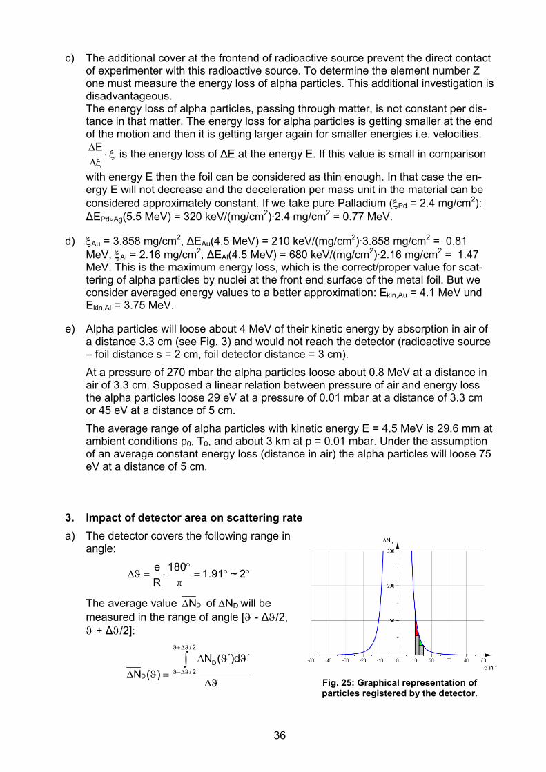
3. Impact of detector area on scattering rate a) The detector covers the following range in
angle:
°Δϑ = ⋅ = ° °
πe 180 1.91 ~ 2R
The average value DNΔ of ΔND will be measured in the range of angle [ϑ - Δϑ/2, ϑ + Δϑ/2]:
/ 2
D/ 2
D
N ( ´)d ´N ( )
ϑ+Δϑ
ϑ−Δϑ
Δ ϑ ϑΔ ϑ =
Δϑ
∫
Fig. 25: Graphical representation of particles registered by the detector.
36
As a consequence ΔND will be determined by measurements larger than expected: If we choose a symmetric interval of scattering angles (±Δϑ/2) the red area is larger than the green area, because the function ΔND(ϑ) is more steep at smaller angles (Fig. 25). The height of DNΔ of the square, formed by grey plus red plus green area with equal width Δϑ is therefore larger than the value ΔND at ϑ. By numeric or ana-lytic calculations we get for example ΔND(10°) = 134.5 and Δ °DN (10 ) = 138.7 .
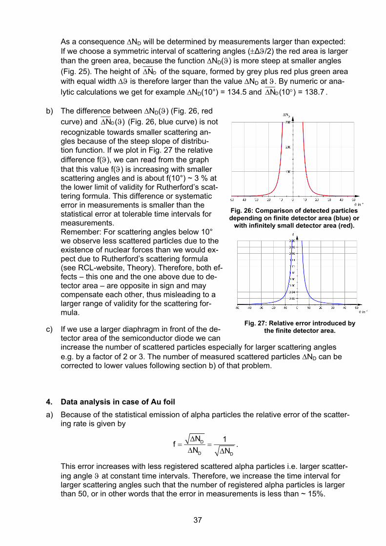
b) The difference between ΔND(ϑ) (Fig. 26, red curve) and DN ( )Δ ϑ (Fig. 26, blue curve) is nrecognizable towards smaller scattering an-gles because of the steep slope of distribu-tion function. If we plot in Fig. 27 the relative difference f(ϑ), we can read from the graph that this value f(ϑ) is increasing with smaller scattering angles and is about f(10°) ~ 3 % at the lower limit of validity for Rutherford’s scat-tering formula. This difference or systematic error in measurements is smaller than the statistical error at tolerable time intervals for measurements. Remember: For scattering angles below 10° we observe less scattered particles due to the existence of nuclear forces than we would ex-pect due to Rutherford’s scattering formula (see RCL-website, Theory). Therefore, both ef-fects – this one and the one above due to de-tector area – are opposite in sign and may compensate each other, thus misleading to a larger range of validity for the scattering for-mula.
Fig. 26: Comparison of detected particles depending on finite detector area (blue) or
with infinitely small detector area (red).
ot
c) If we use a larger diaphragm in front of the de-tector area of the semiconductor diode we can increase the number of scattered particles especially for larger scattering angles e.g. by a factor of 2 or 3. The number of measured scattered particles ΔND can be corrected to lower values following section b) of that problem.
Fig. 27: Relative error introduced by the finite detector area.
4. Data analysis in case of Au foil a) Because of the statistical emission of alpha particles the relative error of the scatter-
ing rate is given by
D
D D
N 1fN NΔ
= =Δ Δ
.
This error increases with less registered scattered alpha particles i.e. larger scatter-ing angle ϑ at constant time intervals. Therefore, we increase the time interval for larger scattering angles such that the number of registered alpha particles is larger than 50, or in other words that the error in measurements is less than ~ 15%.
37

D7D
D D
62
NN 1 1(180 ) 1.11 10 k fN N N kN270.56 1 1N(t) t ct f t 1.5 10 s 17.36 d
s kcfkct
− ΔΔ° = ⋅ = = = =
Δ Δ
= = = ⇔ = ≈ ⋅ =
The calculation delivers a duration of measurements of 17.36 d.
b) If we plot the measured values (Fig. 28) we can hardly recognize an offset in angle. If we fit the measured values by a suited mathematical fit function e.g. Gauss distri-bution (Fig. 29)
20b( )DN a e
s− ϑ−ϑΔ
= ⋅
we can determine the fit parameters a = 10.7 and b = 0.035. These numbers con-firm that we can neglect an offset of angle ϑ0 at ϑ = 0°.
Fig. 29: Determination of offset by means of a Gaussian fit function.
Fig. 28: Graphical representation of measured values.
c) We discuss three kinds how to check an estimated relation – such as y = k·f(x) (e.g. y = kx2) – between measured values (xi|yi) with respect to errors in measurements:
• The ratio i
i
y kf(x )
= is a constant.
• All points (f(xi)|yi) are lying on a line through the origin.
• The constant k as well as further parameters of the function f(x) may be chosen such that all pairs of measured values (xi|yi) will lie on this graph of the function y = k f(x). How good this function y = k f(x) describes all measured values can be controlled by the standard deviation in a regression analysis.
38

In Fig. 30 the measured data are graphically represented. According to Rutherford’s scattering formula all pairs of measured values (sin-4(ϑi/2) |ΔND,i/s) should lie on a line through the origin.
We can read from Fig. 31, that this is fulfilled only for an angle larger than ϑmin (the angle ϑ = 0° is lying at x = ∞, the angle ϑ = 180° at x = 1). The diagram delivers ϑmin ~ 8° from sin-4(ϑmin/2) ~ 43000. The evaluation in Fig. 32 gives the result that all measured values for |ϑ| ≥ 8° are lying on a line through the origin with slope k = 0.00003 s within error limits. For the gold foil we get Z = 85, if we use N = 270.56 (see VI.4a) and insert all technical parameters in
Fig. 31: Determination of the lower limit of scattering angle ϑmin for the validity of
Fig. 30: Graphical representation of measured data as a function of sin-4(ϑ/2).
Rutherford’s scattering formula.
2o kin2
D
8 E kRZe Nnd A
πε=
Δ Fig. 32: Validity of Rutherford’s scattering
formula for |ϑ| ≥ 8°.
(see RCL-website, Theory, 2.2d). The deviation is 6/79 ≡ 8 % and is mainly given by the uncertainty of ≈ 20 % for the exact thickness of gold foil.
d) If we use as a fit function a Gaussian function (see VI.4b) then we can read from the Fig. 33 that the scattering rate for larger scattering angles is too high.
Fig. 33: Description of measured scatter-ing data by a Gaussian function. Fig. 34: Description of measured scatter-
ing data by a power function.
39

If we use instead a power function 4D
4000N ( )s grad
−Δ ϑ = ϑ⋅
we can read from Fig. 34
that this one is as good as Rutherford’s scattering formula.
5. Investigation of further dependencies of scattering rate
a) 2D D D2
kin
1N ~ d, N ~ , N ~ ZE
Δ Δ Δ
b) Following VI.2b we get AuAu
d d ξξ = ρ ⇔ =
ρ.
ξ in mg/cm2 0.29 0.42 0.57 0.85 1.12 1.94 d in μm 0.15 0.21 0.29 0.44 0.58 1.01
ΔND/1000 s 168 283 420 504 780 1236
ϑ = 17.5° Z = 79
Ekin = 5.48 MeV
All measured values are lying on a line within error limits if we plot the scattering rate ΔND versus thick-ness d of gold foil (Fig. 35). If we increase the thickness d of gold foil, we increase the number of scattering Au atoms (supposed single scattering) and, therefore, the number of scattered alpha par-ticles (see I.3b).
c) All measured values are lying on a line within error limits if we plot the scattering rate ΔND versus 1/Ekin,α
2 (Fig. 36). We can vary the energy Ekin of alpha particles by different radioactive sources emitting alpha particles or by the absorption of al-pha particles by differently thick metal foils. In the first case we must look up the energy of alpha particles of different radioactive sources in energy level diagrams or tables of radioactive ma-terials. The disadvantage in that case is the prize of these radioactive sources and the limited number of nuclides which emit mainly alpha particles and much less β-radiation. In the second case we can deter-mine the energy of alpha particles from the thickness of the metal foil applying em-pirical or theoretical formulas like Bethe-Bloch equation. Or we can determine the energy directly by a calibrated multi-channel analyzer.
Fig. 35: Relation between ΔND/1000 s and thickness d of gold foil.
Fig. 36: Relation between ΔND/1000 s and kinetic energy Ekin,α of alpha particles.
40
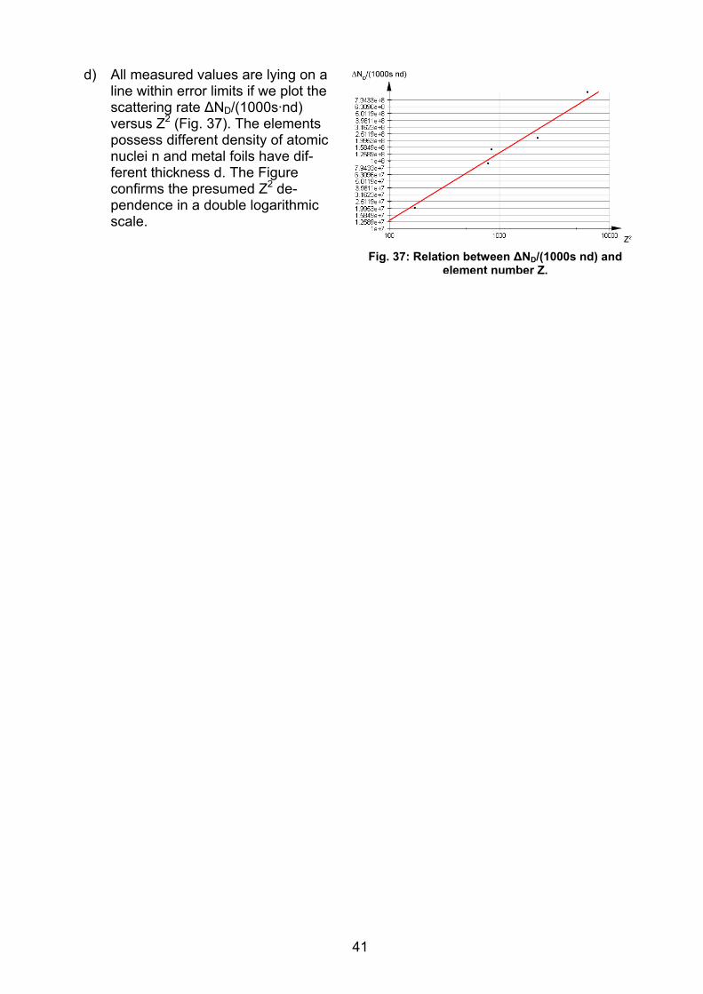
d) All measured values are lying on a line within error limits if we plot the scattering rate ΔND/(1000s·nd) versus Z2 (Fig. 37). The elements possess different density of atomic nuclei n and metal foils have dif-ferent thickness d. The Figure confirms the presumed Z2 de-pendence in a double logarithmic scale.
Fig. 37: Relation between ΔND/(1000s nd) and element number Z.
41

42
VII. References
Since this collection of problems is translated from German version the literature is due to German sources. Similar literature of * is available in English language.
1. Demtröder, W. (2005): Experimentalphysik 3 – Atome, Moleküle, Festkörper, 3. Aufl., Springer, S. 56-66. *
2. Eaton, T. W. & Cheetham, D.: A novel design of Rutherford scattering apparatus, Physics Education 8 (1973) 2, pp 97-101.
3. Geiger, H. & Marsden, E.: The Laws of Deflexion of α Particles through Large An-gles, Philosophical Magazine 25 (1913) 6, pp 604-623, 07-01-10.
4. Grehn, J. & Krause, J. (Hrsg.) (1998): Metzler Physik, 3. Aufl., Schroedel, S. 405-407. *
5. Haken, H. & Wolf, H. C. (1993): Atom- und Quantenphysik, 5. Aufl., Springer, S. 41-51. *
6. Kuhn, W. (Hrsg.) (2000): Handbuch der Experimentalphysik – Sekundarbeich II. Band 10 – Kerne und Teilchen I. Aulis, S. 75-96. *
7. Kuhn, W. (Hrsg.) (2001): Handbuch der Experimentalphysik – Sekundarbeich II. Band 10 – Kerne und Teilchen II. Aulis, S. 1-20. *
8. Meschede, D. (2001): Gerthsen Physik, 21. Aufl., Springer, S. 815-819. * 9. Powersim Constructor Light, for free version see http://wwwu.uni-
klu.ac.at/gossimit/pap.php?uk=7, 07-01-10. 10. Rutherford, E.: The Scattering of α and β Particles by Matter and the Structure of
the Atom, Philosophical Magazine 21 (1911) 6, pp 669-688. 11. http://leifi.physik.uni-
muenchen.de/web_ph12/umwelt_technik/10lenard_kath/atom_lenard.htm, 07-01-10.