Embed Size (px)
Citation preview

2
The Company
3
Manufacturing processTubes are manufactured in the cold drawing plants of SalzgitterMannesmann Precision, and more particularly in Vitry-le-Françoisplant. Tubes are cold drawn from hollows supplied mainly by Salzgitter Mannesmann Rohr Sachsen in Zeithain. Modern and efficient equipment makes it possible to meet the most stringentrequirements and to obtain long unit lengths, up to 87 ft according to sizes.
Cold drawn seamless heat exchanger tubes for Process Industries
Sal
zgitt
er M
anne
sman
n Pr
ecis
ion
Gm
bH, C
old
draw
n se
amle
ss h
eat e
xcha
nger
tube
s fo
r Pr
oces
s In
dust
ries,
002
E 1
2.09

Introduction
2
The Company
3
The tubes described in this brochure are intended for the construction of heat exchange equipment for Process Industries,such as oil refineries, gas condensers or petrochemical plants. These heat exchangers are designed for service temperaturesranging from – 100°C to +625°C (-150°F to 1150°F). Tube parameters (dimensions, steel grade etc) are determined by the design engineers according to the fluids, temperatures andpressures used in the equipment.
Manufacturing processTubes are manufactured in the cold drawing plants of SalzgitterMannesmann Precision, and more particularly in Vitry-le-Françoisplant. Tubes are cold drawn from hollows supplied mainly by Salzgitter Mannesmann Rohr Sachsen in Zeithain. Modern and efficient equipment makes it possible to meet the most stringentrequirements and to obtain long unit lengths, up to 87 ft according to sizes.
Cold drawn seamless heat exchanger tubes for Process Industries
Sal
zgitt
er M
anne
sman
n Pr
ecis
ion
Gm
bH, C
old
draw
n se
amle
ss h
eat e
xcha
nger
tube
s fo
r Pr
oces
s In
dust
ries,
002
E 1
2.09

2
The Company
3
Production of seamless and welded precision steel tubes in accordance to international standards e.g. EN 10305-1, EN 10305-2, EN 10305-3, EN 10305-4, EN 10216 and
EN 10217, ASTM A 179, A192, A 209, A 210, A 213, A 556 Japan Industrial Standard, British Standards, Other standards on inquiry.
0
10
20
30
40
50
100
150
200
300
350380
Wall thickness, mm1 2 3 4 5 6 7 8 9 10 11 12 13 14 15 16 17 18 20 22 25
Outs
ide
diam
eter
, mm
Salzgitter Mannesmann PrecisionFollowing the takeover of Vallourec Précision Etirage (VPE),France, by the Salzgitter AG, the new European market leader of cold-drawn seamless and welded precision steel tubes hasbeen founded under the name of Salzgitter Mannesmann Preci-sion GmbH. As a leading European manufacturer Salzgitter Man-nesmann Precision offers a wide range of products and services with great scope for intelligent, tubing-related solutions.
The Group-StructureEffective synergies are a result of our integration with the Salzgitter Group ensure an outstanding efficiency - from the pre-material to the finished precision steel tube.The affiliated group companies ensure a comprehensive supplyguarantee regarding the complete value-added chain in produc-tion of precision steel tubes and is therewith the basis for the highperformance in deliveries and customer satisfaction.Today, Mannesmannröhren-Werke (MRW) manages the Group'sTube Division. The Division has numerous subsidiaries and affiliated companies.
Salzgitter Mannesmann Precision GmbH
Salzgitter MannesmannPräzisrohr GmbH, Hamm
Hamm
Wickede
Brackwede
Holzhausen
Remscheid *
Salzgitter MannesmannRohr Sachsen GmbH, Zeithain
Zeithain
Salzgitter AG
Mannesmannröhren-Werke GmbH
Salzgitter MannesmannPrécision Etirage SAS, St. Florentin
Salzgitter MannesmannPrecisión S.A. de C.V., Guadalajara
St. Florentin
Vitry
Rachecourt
Tonnerre
La Charité
Guadalajara
*A Company of Salzgitter Mannesmann Stainless Tubes GmbH
Seamless precision steel tubes of special dimensional accuracy according to DIN EN 10305-1Outside diameter: 1.5 - 380 mmWall thicknesses: 0.2 - 25.0 mm
Welded precision steel tubes of special dimensional accuracy according to DIN EN 10305-2Outside diameter: 20 - 120 mmWall thicknesses: 1.0 - 7.5 mm
Welded size-rolled precision steel tubes according toDIN EN 10305-3Outside diameter: 25 - 114.3 mmWall thicknesses: 1.75 - 8.5 mm

4
Technical data
6 7
Table 1: Main steel grades
IdentificationTubes are stencilled according to the specification. Marking and labelling can be adapted to suit your particular needs.
Rust protectionHeat exchanger tubes from SMP can be supplied with three typesof surface finish: without oil, externally oiled or internally and externally oiled. Yourchoice of protection should take into account the end use of thetubes and the means of transport.
PackagingBased on our extensive experience with overseas customers, wecan offer a comprehensive range of packaging solutions adaptedto your needs in bundles or wooden crates.
Technical data
Table 4: U-Bending
All U-bent tubes can be submitted with the following operations or tests:
• Stress relieving of the bend + 150 mm (5.9") of each leg (standard), over 150 mm upon request,• Hydrostatic test up to 800 bars (11 603 psi) for radii up to 1100 mm (43“),• Magnetic particle test for radii up to 500 mm (20“),• Ultrasonic test of the wall thickness on the bend.
U-bent tubes are shipped in specially designed wooden boxes or crates depending on the destination.
Wall thickness1.50 mm to 3.81 mm.059“ to .150“
Developed lengthMini 2.6 m max 26.500 mMini 8 1/2“ max 86,95‘
Radius of bend min. 1.5 x OD max 1250 mm (49‘)
Outside diameter15.88 mm to 31.75 mm5/8“ to 1.25“
U-bent tubes are shipped in specially designed wooden boxes or crates depending on the destination.
5
TestsAt each manufacturing stage, heat exchanger tubes are submitted to a visual and dimensional inspection. They are also submitted to Eddy current test (straighttubes) or, if requested, to other non destructive tests in accordance with the requi-rements of the standards and customers’ specifications. Mechanical tests, alongwith flaring and flattening tests, are performed on samples of each order as perthe reference standards.
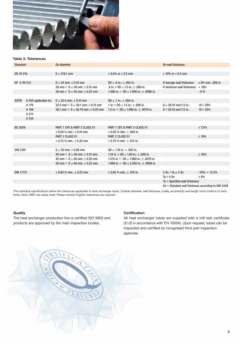
QualityThe heat exchanger production line is certified ISO 9002 and products are approved by the main inspection bodies.
CertificationAll heat exchanger tubes are supplied with a mill test certificate(3.1.B in accordance with EN 10204). Upon request, tubes can be inspected and certified by recognised third part inspection agencies.
Service Steel EN NF A 49-215 DIN BS ASTM UNItemperature grades 10216-2 17175 3059-3601 A 179, A 192 5462range 10216-3 17173 3602-3603 A 209, A 213 663
10216-4 17179 3604-3606 A 334, A 210, A 199
Low C Ni P215 NL Gr 1temperature P265 NL TU 42 BT TTST 35N Gr 6-Gr A1
Gr 3
Medium C Mn P195 GH TU 37-C St 35.8 320/360 Gr A 179temperature P235 GH TU 42-C St 45.8 410 Gr A192 Fe 35.2/C 14
P265 GH TU 48-C 440/460 Gr C C18/Fe 45.2
High 0.3 Motemperature 0.5 Mo 16 Mo 3 TU 15 D 3 15 Mo 3 243 T1 16 Mo 5
0.5 Cr 0.5 Mo TU 15 CD 2-05 T1A1 Cr 0.5 Mo 13CrMo 4-5 620 T121.25 Cr 0.5 Mo 10CrMo 5-5 TU 10 CD 5-05 13 Cr Mo 4-4 T11 14 Cr Mo 35Cr 0.5 Mo X11CrMo5+NT11
TU Z10 CD5-05 T52.25 Cr 1 Mo 10CrMo9-10
TU 10 CD 9-10 10 CrMo9-10 622-490 T22 12CrMo9-10
Steel grades is for information. Other grades are available upon request
The individual specifications define the tolerances applicable to heat exchanger tubes. Outside diameter, wall thickness, ovality, eccentricity and length must conform to strict limits, which SMP can easily meet. Please consult if tighter tolerances are required.
Table 3: Tolerances
Standard On diameter On wall thickness
EN 10 216 D ≤ 219,1 mm ± 0.5% or ± 0.3 mm ± 10% or ± 0.2 mm
NF A 49-215 D ≤ 20 mm: ± 0.10 mm OD ≤ .8 in.: ± .004 in. If average wall thickness: ± 9% min. .008 in.20 mm < D ≤ 38 mm: ± 0.15 mm .8 in. < OD ≤ 1.5 in.: ± .006 in. If minimum wall thickness: + 18% 38 mm < D ≤ 50 mm: ± 0.25 mm 1.496 in. < OD ≤ 1.969 in.: ± .0098 in. - 0 %
ASTM A 450 applicable for: D ≤ 25.4 mm: ± 0.10 mm OD ≤ .1 in.: ± .004 in.A 179 25.4 mm < D ≤ 38.1 mm: ± 0.15 mm 1 in. < OD ≤ 1.5 in.: ± .006 in. D ≤ 38.10 mm/1.5 in.: -0/+ 20%A 199 38.1 mm < D ≤ 50.79 mm: ± 0.20 mm 1.5 in. < OD ≤ 1.999 in.: ± .0079 in. D > 38.10 mm/1.5 in.: -0/+ 22%A 213A 334
BS 3059 PART 1 CFS & PART 2 CLASS S1 PART 1 CFS & PART 2 CLASS S1 ± 7.5%± 0.50 % min.: ± 0.10 mm ± 0.50 % min.: ± .004 in.PART 2 CLASS S1 PART 2 CLASS S1 ± 10%± 0.75 % min.: ± 0.30 mm ± 0.75 % min.: ± .012 in.
DIN 2391 D ≤ 30 mm: ± 0.08 mm OD ≤ 1.18 in.: ± .003 in.30 mm < D ≤ 40 mm: ± 0.15 mm 1.18 in. < OD ≤ 1.60 in.: ± .006 in. ± 10%40 mm < D ≤ 50 mm: ± 0.20 mm 1.574 in. < OD ≤ 1.969 in.: ± .0079 in.50 mm < D ≤ 60 mm: ± 0.25 mm 1.969 in. < OD ≤ 2.362 in.: ± .0098 in.
DIN 17175 ± 0.60 % min.: ± 0.25 mm ± 0.60 % min.: ± .010 in. 2 Sn < Ta ≤ 4 Sn -10%/ + 12.5%Ta > 4 Sn ± 9%Ta = Specified wall thicknessSn = Standard wall thickness according to DIN 2448
Table 2: Outside diameter and wall thickness
1 Ib/ft = 1.48816 kg/m 1 kg/m= 0.67197 lb/ft
Average wall thickness: (OD – WT) x WT x 0,0246615 Kg/m
O.D/wt BWG 16 14 13 12 11 10inch mm 1.50 1.65 2.00 2.11 2.41 2.50 2.77 3.00 3.05 3.40 4.00
15.00 0.499 0.641 0.771 0.8885/8 15.87 0.579 0.716 0.800 0.895
16.00 0.691 0.832 0.96218.00 0.610 0.789 0.956 1.110
3/4 19.05 0.708 0.881 0.989 1.112 1.203 1.31220.00 0.888 1.079 1.25822.00 0.986 1.202 1.40625.00 1.134 1.387 1.628 2.072
1 25.40 0.966 1.212 1.366 1.546 1.681 1.84528.00 1.282 1.572 1.850 2.36830.00 1.381 1.695 1.998 2.565
1 1/4 31.75 1.542 1.744 1.980 2.159 2.37735.00 1.628 2.004 2.368
1 1/2 38.10 1.873 2.121 2.413 2.636 2.9102 50.80 2.534 2.876 3.281 3.592 3.9742.37 60.30 3.563 3.930 4.239 4.306 4.771 5.5532 1/2 63.50 3.761 4.148 4.476 4.547 5.040 5.870
1 Ib/ft = 1.48816 kg/m 1 kg/m= 0.67197 Ib/ft Above is an indication of the must usual sizes. Please inquire for other dimensions.
Minimum wall thickness: (OD – 1,1 WT) x 1,1 WT x 0,0246615 Kg/m
O.D/wt BWG 16 14 13 12 11 10inch mm 1.50 1.65 2.00 2.11 2.41 2.50 2.77 3.00 3.05 3.40 4.00
15.00 0.543 0.694 0.831 0.9525/8 15.87 0.629 0.776 0.864 0.964
16.00 0.749 0.899 1.03418.00 0.665 0.857 1.034 1.196
3/4 19.05 0.771 0.958 1.072 1.203 1.299 1.41220.00 0.966 1.170 1.35922.00 1.074 1.306 1.52225.00 1.237 1.509 1.766 2.235
1 25.40 1.056 1.321 1.487 1.680 1.824 1.99828.00 1.400 1.712 2.010 2.56130.00 1.508 1.848 2.173 2.778
1 1/4 31.75 1.684 1.902 2.157 2.349 2.58335.00 1.780 2.187 2.580
1 1/2 38.10 2.048 2.318 2.634 2.8752 50.80 2.775 3.148 3.588 3.926 4.3412.37 60.30 3.903 4.302 4.638 4.711 5.216 6.0652 1/2 63.50 4.120 4.542 4.899 4.976 5.512 6.412

4
Technical data
6 7
Table 1: Main steel grades
IdentificationTubes are stencilled according to the specification. Marking and labelling can be adapted to suit your particular needs.
Rust protectionHeat exchanger tubes from SMP can be supplied with three typesof surface finish: without oil, externally oiled or internally and externally oiled. Yourchoice of protection should take into account the end use of thetubes and the means of transport.
PackagingBased on our extensive experience with overseas customers, wecan offer a comprehensive range of packaging solutions adaptedto your needs in bundles or wooden crates.
Technical data
Table 4: U-Bending
All U-bent tubes can be submitted with the following operations or tests:
• Stress relieving of the bend + 150 mm (5.9") of each leg (standard), over 150 mm upon request,• Hydrostatic test up to 800 bars (11 603 psi) for radii up to 1100 mm (43“),• Magnetic particle test for radii up to 500 mm (20“),• Ultrasonic test of the wall thickness on the bend.
U-bent tubes are shipped in specially designed wooden boxes or crates depending on the destination.
Wall thickness1.50 mm to 3.81 mm.059“ to .150“
Developed lengthMini 2.6 m max 26.500 mMini 8 1/2“ max 86,95‘
Radius of bend min. 1.5 x OD max 1250 mm (49‘)
Outside diameter15.88 mm to 31.75 mm5/8“ to 1.25“
U-bent tubes are shipped in specially designed wooden boxes or crates depending on the destination.
5
TestsAt each manufacturing stage, heat exchanger tubes are submitted to a visual and dimensional inspection. They are also submitted to Eddy current test (straighttubes) or, if requested, to other non destructive tests in accordance with the requi-rements of the standards and customers’ specifications. Mechanical tests, alongwith flaring and flattening tests, are performed on samples of each order as perthe reference standards.
QualityThe heat exchanger production line is certified ISO 9002 and products are approved by the main inspection bodies.
CertificationAll heat exchanger tubes are supplied with a mill test certificate(3.1.B in accordance with EN 10204). Upon request, tubes can be inspected and certified by recognised third part inspection agencies.
Service Steel EN NF A 49-215 DIN BS ASTM UNItemperature grades 10216-2 17175 3059-3601 A 179, A 192 5462range 10216-3 17173 3602-3603 A 209, A 213 663
10216-4 17179 3604-3606 A 334, A 210, A 199
Low C Ni P215 NL Gr 1temperature P265 NL TU 42 BT TTST 35N Gr 6-Gr A1
Gr 3
Medium C Mn P195 GH TU 37-C St 35.8 320/360 Gr A 179temperature P235 GH TU 42-C St 45.8 410 Gr A192 Fe 35.2/C 14
P265 GH TU 48-C 440/460 Gr C C18/Fe 45.2
High 0.3 Motemperature 0.5 Mo 16 Mo 3 TU 15 D 3 15 Mo 3 243 T1 16 Mo 5
0.5 Cr 0.5 Mo TU 15 CD 2-05 T1A1 Cr 0.5 Mo 13CrMo 4-5 620 T121.25 Cr 0.5 Mo 10CrMo 5-5 TU 10 CD 5-05 13 Cr Mo 4-4 T11 14 Cr Mo 35Cr 0.5 Mo X11CrMo5+NT11
TU Z10 CD5-05 T52.25 Cr 1 Mo 10CrMo9-10
TU 10 CD 9-10 10 CrMo9-10 622-490 T22 12CrMo9-10
Steel grades is for information. Other grades are available upon request
The individual specifications define the tolerances applicable to heat exchanger tubes. Outside diameter, wall thickness, ovality, eccentricity and length must conform to strict limits, which SMP can easily meet. Please consult if tighter tolerances are required.
Table 3: Tolerances
Standard On diameter On wall thickness
EN 10 216 D ≤ 219,1 mm ± 0.5% or ± 0.3 mm ± 10% or ± 0.2 mm
NF A 49-215 D ≤ 20 mm: ± 0.10 mm OD ≤ .8 in.: ± .004 in. If average wall thickness: ± 9% min. .008 in.20 mm < D ≤ 38 mm: ± 0.15 mm .8 in. < OD ≤ 1.5 in.: ± .006 in. If minimum wall thickness: + 18% 38 mm < D ≤ 50 mm: ± 0.25 mm 1.496 in. < OD ≤ 1.969 in.: ± .0098 in. - 0 %
ASTM A 450 applicable for: D ≤ 25.4 mm: ± 0.10 mm OD ≤ .1 in.: ± .004 in.A 179 25.4 mm < D ≤ 38.1 mm: ± 0.15 mm 1 in. < OD ≤ 1.5 in.: ± .006 in. D ≤ 38.10 mm/1.5 in.: -0/+ 20%A 199 38.1 mm < D ≤ 50.79 mm: ± 0.20 mm 1.5 in. < OD ≤ 1.999 in.: ± .0079 in. D > 38.10 mm/1.5 in.: -0/+ 22%A 213A 334
BS 3059 PART 1 CFS & PART 2 CLASS S1 PART 1 CFS & PART 2 CLASS S1 ± 7.5%± 0.50 % min.: ± 0.10 mm ± 0.50 % min.: ± .004 in.PART 2 CLASS S1 PART 2 CLASS S1 ± 10%± 0.75 % min.: ± 0.30 mm ± 0.75 % min.: ± .012 in.
DIN 2391 D ≤ 30 mm: ± 0.08 mm OD ≤ 1.18 in.: ± .003 in.30 mm < D ≤ 40 mm: ± 0.15 mm 1.18 in. < OD ≤ 1.60 in.: ± .006 in. ± 10%40 mm < D ≤ 50 mm: ± 0.20 mm 1.574 in. < OD ≤ 1.969 in.: ± .0079 in.50 mm < D ≤ 60 mm: ± 0.25 mm 1.969 in. < OD ≤ 2.362 in.: ± .0098 in.
DIN 17175 ± 0.60 % min.: ± 0.25 mm ± 0.60 % min.: ± .010 in. 2 Sn < Ta ≤ 4 Sn -10%/ + 12.5%Ta > 4 Sn ± 9%Ta = Specified wall thicknessSn = Standard wall thickness according to DIN 2448
Table 2: Outside diameter and wall thickness
1 Ib/ft = 1.48816 kg/m 1 kg/m= 0.67197 lb/ft
Average wall thickness: (OD – WT) x WT x 0,0246615 Kg/m
O.D/wt BWG 16 14 13 12 11 10inch mm 1.50 1.65 2.00 2.11 2.41 2.50 2.77 3.00 3.05 3.40 4.00
15.00 0.499 0.641 0.771 0.8885/8 15.87 0.579 0.716 0.800 0.895
16.00 0.691 0.832 0.96218.00 0.610 0.789 0.956 1.110
3/4 19.05 0.708 0.881 0.989 1.112 1.203 1.31220.00 0.888 1.079 1.25822.00 0.986 1.202 1.40625.00 1.134 1.387 1.628 2.072
1 25.40 0.966 1.212 1.366 1.546 1.681 1.84528.00 1.282 1.572 1.850 2.36830.00 1.381 1.695 1.998 2.565
1 1/4 31.75 1.542 1.744 1.980 2.159 2.37735.00 1.628 2.004 2.368
1 1/2 38.10 1.873 2.121 2.413 2.636 2.9102 50.80 2.534 2.876 3.281 3.592 3.9742.37 60.30 3.563 3.930 4.239 4.306 4.771 5.5532 1/2 63.50 3.761 4.148 4.476 4.547 5.040 5.870
1 Ib/ft = 1.48816 kg/m 1 kg/m= 0.67197 Ib/ft Above is an indication of the must usual sizes. Please inquire for other dimensions.
Minimum wall thickness: (OD – 1,1 WT) x 1,1 WT x 0,0246615 Kg/m
O.D/wt BWG 16 14 13 12 11 10inch mm 1.50 1.65 2.00 2.11 2.41 2.50 2.77 3.00 3.05 3.40 4.00
15.00 0.543 0.694 0.831 0.9525/8 15.87 0.629 0.776 0.864 0.964
16.00 0.749 0.899 1.03418.00 0.665 0.857 1.034 1.196
3/4 19.05 0.771 0.958 1.072 1.203 1.299 1.41220.00 0.966 1.170 1.35922.00 1.074 1.306 1.52225.00 1.237 1.509 1.766 2.235
1 25.40 1.056 1.321 1.487 1.680 1.824 1.99828.00 1.400 1.712 2.010 2.56130.00 1.508 1.848 2.173 2.778
1 1/4 31.75 1.684 1.902 2.157 2.349 2.58335.00 1.780 2.187 2.580
1 1/2 38.10 2.048 2.318 2.634 2.8752 50.80 2.775 3.148 3.588 3.926 4.3412.37 60.30 3.903 4.302 4.638 4.711 5.216 6.0652 1/2 63.50 4.120 4.542 4.899 4.976 5.512 6.412

Salzgitter Mannesmann Precision Etirage SAS
Direct Contact Sales:Avenue Jean JuifBP 77 – Z.I.51300 Vitry-le-François, France
Phone: +33 3 26 41 23 00Fax: +33 3 26 41 23 32E-mail: [email protected]
Salzgitter Mannesmann Precision GmbH
Wiesenstraße 3645473 Mülheim/Ruhr, Germany
www.smp-tubes.com
Your local contact:
Sal
zgitt
er M
anne
sman
n Pr
ecis
ion
Gm
bH, C
old
draw
n se
amle
ss h
eat e
xcha
nger
tube
s fo
r Pr
oces
s In
dust
ries,
002
E 1
2.09