Embed Size (px)
Citation preview

ADVANCED ENGINE MANAGEMENT INC. 2205 126TH Street, Unit A Hawthorne, CA. 90250
Phone: (310) 484-2322 Fax: (310) 484-0152 www.aempower.com
Instructions Part Number: 10-7019 2003 Infiniti G35 VQ35DE 3.5L C.A.R.B. E.O. #D-392-24
2004-2005 Infiniti G35 VQ35DE 3.5L C.A.R.B. E.O. #Pending © Copyright 2003
COLD AIR
SYSTEM
Installation Instructions for: Part Number 21-548
2003-2005 Infiniti G35

Congratulations! You have just purchased the finest Air Induction & Filtration system for your car at any price! The AEM Cold Air Intake System is the result of extensive development on a wide variety of cars. It is the most advanced Cold Air Intake System on the market. Each system is specifically engineered for its application. All AEM Cold Air Intake Systems deliver maximum performance gains through lightweight, all-aluminum, mandrel-bent tubing that is tuned in both length and diameter. The aluminum will not crack in extended use like plastic. The tube length and diameter are matched for each specific engine to give power over a broad RPM range. Unlike plastic systems that use a continually diverging cross-section, we take advantage of the acoustical energy in the inlet duct to promote cylinder filling during the intake valve-opening event. Every intake is coated with a high-gloss, heat-reducing Zirconia based powder coating. This special blend of powder coating helps reduce heat penetration, which in turn reduces the temperature of the inlet air charge. The cooler inlet air temperature translates to more power during the combustion process because cool air is denser than warm air. The filter element has also been extensively developed. An integral part of all our filter elements is a built-in velocity stack. This velocity stack is specifically engineered to improve the aerodynamic efficiency of the intake system. We have seen airflow gains on a flow bench of 12-15% by using this velocity stack. The air mass flow to the engine is increased because of the increased airflow and reduced inlet temperature, which translates to more power. Bill of Materials for: 21-548
1 2-548 Upper intake pipe 1 2-549 Lower intake pipe 1 21-203 3" air filter & Clamp 1 103-BLO-5220 #52 Hose Clamp 5 103-BLO-4820 #48 hose clamp 2 5-300 3" x 3" silicone Hose 1 2-641 Nissan MAF adaptor 4 1-2030 BOLT,HEX M6 X 1 X 16 4 1-3018 WASHER, M6 ZINC-PLATED STEEL 1 444.460.04 6mm Nylok Nut 1 1228599 Rubber Mount 1" x 6mm 1 559999 Washer, Flat M6x25x1 1 5-323 HOSE,ADAPTER 3.25/3.00 X 2.25" BLK 1 10-7019 Installation instructions 2 10-922S AEM Large Decal - Silver 1 10-400W AEM Lic Plate Frame - White 1 10-922E300 EMBLEM,CAS/SRS 3.00R

Read and understand these instructions BEFORE attempting to install this product. Note: This inlet pipe kit may require the removal and reinstallation of emissions related components. If you are not familiar with the installation and/or the operation of these components then please refer this installation to a qualified professional.
This installation will also require access to the underside of the vehicle. If a lift is not available, jack up the front of the vehicle and support it with jack stands. Make sure vehicle is stable before working under it.
1) Getting started a) Make sure the vehicle is parked on a level surface and set parking brake. b) Remove left front wheel. c) Disconnect negative battery terminal. d) If engine has run within the past two hours let it cool down. e) Check contents of package with list on previous page f) Make sure AEM intake components are free of packaging material.
2) Removing the stock air inlet system
a) Remove the four fasteners holding on the engine cover. Remove the engine cover.
b) Remove the two plastic fasteners holding on the air duct and remove the duct from the engine bay.
c) Loosen the hose clamp holding the stock intake tube on the throttle body. Loosen the spring hose clamp on the breather hose and pull the hose off of the fitting on the intake tube.
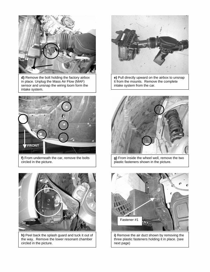
d) Remove the bolt holding the factory airbox in place. Unplug the Mass Air Flow (MAF) sensor and unsnap the wiring loom form the intake system.
e) Pull directly upward on the airbox to unsnap it from the mounts. Remove the complete intake system from the car.
f) From underneath the car, remove the bolts circled in the picture.
FRONT
g) From inside the wheel well, remove the two plastic fasteners shown in the picture.
h) Peel back the splash guard and tuck it out of the way. Remove the lower resonant chamber circled in the picture.
i) Remove the air duct shown by removing the three plastic fasteners holding it in place. (see next page)
Fastener #1

3) Installing the AEM Cold Air Intake System
When installing the Cold Air Intake System, DO NOT completely tighten the hose clamps or mounting tab hardware until instructed to do so later in these instructions.
BBER MOUNT
ACER
Fastener #2
View Through Grille. View from underneath.
Fastener #3
j) Remove the four bolts holding the MAF sensor on the factory airbox. Handle the MAF sensor with care.
a) Using the 6mm bolts and washers included in the kit, bolt the MAF sensor to the AEM adaptor.
b) Slide one of the 3” straight silicone couplers over the MAF sensor as shown. Lightly oiling the inside of the coupler may help. Secure the coupler in place using a #48 hose clamp.
Note: The G35 sedan has foam insert attached to the plastic duct. Remove the whole assembly.

c) Place the 3.25”-3.0” reducing silicone coupler on the throttle body. Use a #52 hose clamp around the throttle body. Make sure the coupler is sitting squarely on the throttle body and tighten the #52 hose clamp. Loosely install a #48 hose clamp on the other end of the coupler.
d) Insert the upper intake pipe in the coupler as shown. Reuse the factory hose clamp and install the breather hose on the fitting on the pipe. Do not tighten the #48 hose clamp.
e) Install the assembly from step 3-b on the upper intake pipe. Loosely install a #48 hose clamp on the coupler. Make sure the MAF sensor connector is pointing toward the oil cap.
f) Install the other 3” silicone coupler on the end of the AEM MAF adaptor. Loosely install two #48 hose clamps.
g) Thread the rubber mount into the hole that held the resonant chamber rear mounting bolt. Hand tighten the rubber mount.
h) If installing on a G35 Sedan, remove the mounting screw for the HID Headlight controller. Ignore step 3-h and 3-i if installing on a G35 Coupe.

Rubber Mount
Support Bracket
Fender Washer
Nut
k) Install the AEM air filter on the end of the lower intake pipe. Make sure the filter is fully and squarely seated on the end of the pipe. Use a #52 hose clamp to secure it in place.
l) Plug in the MAF senor. Place the engine cover on the intake manifold and check for clearance of the MAF sensor plug. Rotate the MAF sensor assembly until the plug has adequate clearance
j) Install the lower intake pipe in the end of the coupler on the AEM MAF adaptor. Line up the bracket on the pipe with the rubber mount and install the 6mm nylock nut and fender washer according to the diagram below. Do not tighten.
Note: If a Bypass valve is to be used install it in the circled section of pipe. Bypass valve part number for this system is: 20-403S
NOTE
i) Rotate the HID controller forward and reinstall the screw in the other mounting hole on the controller. Pull excess slack for the wires from farther up the harness if needed.
For Technical Inquiries
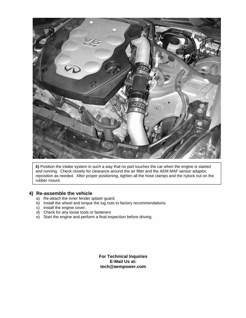
4) Re-assemble the vehicle
a) Re-attach the inner fender splash guard. b) Install the wheel and torque the lug nuts to factory recommendations. c) Install the engine cover. d) Check for any loose tools or fasteners e) Start the engine and perform a final inspection before driving.
For Technical Inquiries E-Mail Us at:
k) Position the intake system in such a way that no part touches the car when the engine is started and running. Check closely for clearance around the air filter and the AEM MAF sensor adaptor, reposition as needed. After proper positioning, tighten all the hose clamps and the nylock nut on the rubber mount.