Embed Size (px)
Citation preview

Diesel Mechanic: Module CLU
- Mining Qualifications Authority - All rights reserved
Created : 01 February 2003
Revised : March 2015
Owner : Learnership Department
First Published : March 2003
Revision No: 002
TRG 9
Page 1 of 45
DIESEL MECHANIC
CODE: CLU
MAINTAIN CLUTCHES

Diesel Mechanic: Module CLU
- Mining Qualifications Authority - All rights reserved
Created : 01 February 2003
Revised : March 2015
Owner : Learnership Department
First Published : March 2003
Revision No: 002
TRG 9
Page 2 of 45
INDEX
The following elements are contained in this learning guide:
TOPIC PAGE NUMBER
Index 2
Module Objective and Additional resources 3
HIAC 4
Operation of clutches 5 - 12
Adjusting the cable-operated clutch 13
Checking and adjusting a hydraulic clutch 14 - 15
Servicing a Clutch 16 - 18
Clutch removal and installation 19 - 21
Inspection and repair 22 - 42
Fault Finding 43
Self-test 44
Practice 45

Diesel Mechanic: Module CLU
- Mining Qualifications Authority - All rights reserved
Created : 01 February 2003
Revised : March 2015
Owner : Learnership Department
First Published : March 2003
Revision No: 002
TRG 9
Page 3 of 45
OBJECTIVE WHAT YOU MUST DO 1. Strip, inspect, assemble and adjust a friction plate clutch. 2. State the possible causes for:
(a) the clutch not releasing, and (b) the clutch slipping. (c) the clutch grabbing or shudder
WHAT YOU WILL BE GIVEN 1. An engine fitted with a friction plate clutch. 2. All the necessary tools and equipment. HOW WELL YOU MUST DO IT 1. The clutch pedal height must be within specification. 2. The pedal free play must be within specification. 3. The push rod play must be within specification 4. When the clutch pedal is depressed, the transmission shaft must be able to be
turned freely by hand. 5. When the transmission shaft is turned with the clutch lever having been released, the
clutch must not slip. 6. There must not be any damage to the parts, tools or equipment. 7. All the bolts and nuts must be torqued to specification. ADDITIONAL RESOURCES 1. A demonstration by a competent person, e.g. your Instructor.
2. Audiovisual aids if available.

Diesel Mechanic: Module CLU
- Mining Qualifications Authority - All rights reserved
Created : 01 February 2003
Revised : March 2015
Owner : Learnership Department
First Published : March 2003
Revision No: 002
TRG 9
Page 4 of 45
HAZARD IDENTIFICATION AND CONTROL (HIAC) FORM
CLU
MAINTAIN A CLUTCH
STEPS IN OPERATION / PROCESS
POTENTIAL ACCIDENT / INCIDENT
CONTROLS (BY RESPONSIBLE PERSON)
Use hand tools
Use special tools
Bleeding of hydraulic system
Using damaged tools or wrong tools for the job can cause injury and damage to equipment.
Be aware of High pressure when bleeding clutches
Always use the correct tool for the job.
Ensure tools are in good condition.
Use tools correctly.
Wear appropriate PPE where necessary.
Always take good care of tools. Maintain, clean and store it properly.
NOTE: Before doing the practical work contained in this module, the learner must study the content of the above HIAC Form again and then sign the statement below: The above risks, which will be encountered in this module, are fully understood and will be controlled during the practical work. Signature of Learner:…………………………………… Signature of Training Officer:…………………………….. Date:………………………….

Diesel Mechanic: Module CLU
- Mining Qualifications Authority - All rights reserved
Created : 01 February 2003
Revised : March 2015
Owner : Learnership Department
First Published : March 2003
Revision No: 002
TRG 9
Page 5 of 45
MAINTAIN A CLUTCH ITEM / TASK: Introduction DESCRIPTION: A clutch is a mechanism which couples two shafts together, thereby enabling them to revolve together. It may also uncouple the shafts so that they are free from one another. There are two basic types, namely the positive clutch and the friction clutch. Square-jaw-type Positive clutch (Fig. 1). Friction clutch (Fig. 2).
Fig 1
Fig 2

Diesel Mechanic: Module CLU
- Mining Qualifications Authority - All rights reserved
Created : 01 February 2003
Revised : March 2015
Owner : Learnership Department
First Published : March 2003
Revision No: 002
TRG 9
Page 6 of 45
In a car with a manual gearbox, the first stage in the transmission system is the clutch. It transmits engine power to the gearbox and allows transmission to be interrupted either while a gear is being selected to move off from a stationary position or when gears are changed while the car is moving. Most cars use a friction clutch that is operated either by fluid (hydraulic) or by a cable. When a car is moving under power, the clutch is engaged. A pressure plate bolted to the flywheel exerts constant force, by means of a diaphragm spring, on the driven (or friction) plate. Some cars have a series of coil springs, instead of a diaphragm spring, at the back of the pressure plate. The driven plate runs on a splined input shaft, through which the power is transmitted to the gearbox. The plate has friction linings, similar to brake linings, on both its faces. These allow the drive to be taken up smoothly when the clutch is engaged. Friction clutch (Fig.3).
Fig 3

Diesel Mechanic: Module CLU
- Mining Qualifications Authority - All rights reserved
Created : 01 February 2003
Revised : March 2015
Owner : Learnership Department
First Published : March 2003
Revision No: 002
TRG 9
Page 7 of 45
Operation principles of Friction clutches A sanding disc, driven by a power drill corresponds to the flywheel of a car, driven by the engine (Fig. 4). If a second sanding disc is brought into contact with the first, friction makes it revolve too but moves slowly (Fig. 5). Under increased pressure the two sanding discs revolve as one. This is how a friction clutch works (Fig. 6 on the next page).
Fig 4
Fig 5

Diesel Mechanic: Module CLU
- Mining Qualifications Authority - All rights reserved
Created : 01 February 2003
Revised : March 2015
Owner : Learnership Department
First Published : March 2003
Revision No: 002
TRG 9
Page 8 of 45
FRICTION CLUTCHES Two kinds of friction clutches are used in the mining industry:
a) the multi-disc friction type
b) the plate-friction type Multi-Disc Friction Clutches These clutches are occasionally used for transmitting high powers. They are also used on a driveshaft to protect the motor from becoming overloaded. (When the motor is loaded to its maximum the clutch will start to slip) (Fig.7).
Fig 6
Fig 7

Diesel Mechanic: Module CLU
- Mining Qualifications Authority - All rights reserved
Created : 01 February 2003
Revised : March 2015
Owner : Learnership Department
First Published : March 2003
Revision No: 002
TRG 9
Page 9 of 45
This type of clutch may be regarded as a series of single plate clutches connected together in such a manner that all the friction plates are attached to the driving shaft by means of splines on the shaft. The metal contact plates are attached to the driven shaft by means of splines in the clutch housing. The friction and metal plates can also slide along the shaft and clutch housing. Plate Friction Clutch This type of clutch is going to be discussed in detail in this module because it is the type most commonly used in any vehicle. Operation When the clutch pedal is released (engaged) the pressure plate comes into contact with the clutch plate (disc) and presses it until it comes into contact with the flywheel. The pressure of the clutch spring keeps the three plates in firm contact with one another. (Fig.8). When the clutch is disengaged (i.e. when the pedal is depressed), an arm pushes a release bearing (throw-out bearing) against the centre of the diaphragm spring, which releases the clamping pressure. As a result, the outer part of the pressure plate, which has a large friction surface, no longer clamps the driven plate to the flywheel, so the transmission of power is interrupted and the gears can be changed. When the clutch pedal is released, the release bearing is withdrawn and the diaphragm-spring load once again clamps the driven plate to the flywheel so as to resume the transmission of power.
Fig 8

Diesel Mechanic: Module CLU
- Mining Qualifications Authority - All rights reserved
Created : 01 February 2003
Revised : March 2015
Owner : Learnership Department
First Published : March 2003
Revision No: 002
TRG 9
Page 10 of 45
Dismantled clucth
1. flywheel
2. flywheel bolt(to crankshaft)
3. clutch friction plate
4. pressure plate
5. pressure plate bolts(to flywheel)
6. pilot bearing(for inputshaft of gearbox)
Exploded view of a Dismantled clucth (Fig 9).
Some cars have a hydraulically operated clutch. Pressure on the clutch pedal inside the car activates a piston in a master cylinder, which transmits the pressure through a fluid-filled pipe to a slave cylinder mounted on the gearbox. The slave-cylinder piston is connected to the clutch release arm. (Fig10).
Fig 9
Fig 10
Diesel Mechanic: Module CLU
- Mining Qualifications Authority - All rights reserved
Created : 01 February 2003
Revised : March 2015
Owner : Learnership Department
First Published : March 2003
Revision No: 002
TRG 9
Page 11 of 45
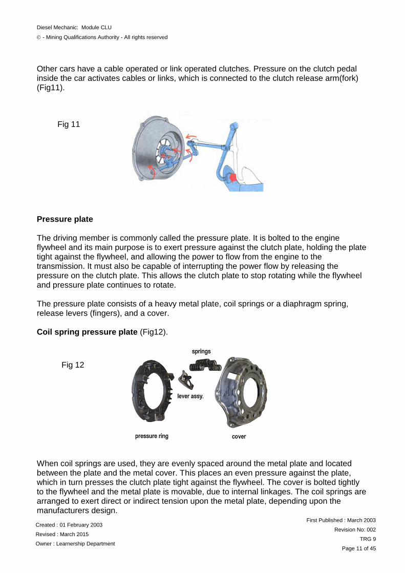
Other cars have a cable operated or link operated clutches. Pressure on the clutch pedal inside the car activates cables or links, which is connected to the clutch release arm(fork) (Fig11). Pressure plate The driving member is commonly called the pressure plate. It is bolted to the engine flywheel and its main purpose is to exert pressure against the clutch plate, holding the plate tight against the flywheel, and allowing the power to flow from the engine to the transmission. It must also be capable of interrupting the power flow by releasing the pressure on the clutch plate. This allows the clutch plate to stop rotating while the flywheel and pressure plate continues to rotate. The pressure plate consists of a heavy metal plate, coil springs or a diaphragm spring, release levers (fingers), and a cover. Coil spring pressure plate (Fig12). When coil springs are used, they are evenly spaced around the metal plate and located between the plate and the metal cover. This places an even pressure against the plate, which in turn presses the clutch plate tight against the flywheel. The cover is bolted tightly to the flywheel and the metal plate is movable, due to internal linkages. The coil springs are arranged to exert direct or indirect tension upon the metal plate, depending upon the manufacturers design.
Fig 12
Fig 11
Diesel Mechanic: Module CLU
- Mining Qualifications Authority - All rights reserved
Created : 01 February 2003
Revised : March 2015
Owner : Learnership Department
First Published : March 2003
Revision No: 002
TRG 9
Page 12 of 45
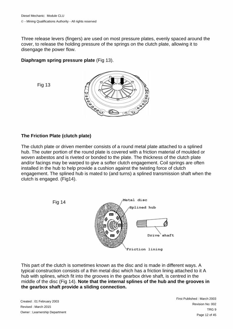
Three release levers (fingers) are used on most pressure plates, evenly spaced around the cover, to release the holding pressure of the springs on the clutch plate, allowing it to disengage the power flow. Diaphragm spring pressure plate (Fig 13). The Friction Plate (clutch plate) The clutch plate or driven member consists of a round metal plate attached to a splined hub. The outer portion of the round plate is covered with a friction material of moulded or woven asbestos and is riveted or bonded to the plate. The thickness of the clutch plate and/or facings may be warped to give a softer clutch engagement. Coil springs are often installed in the hub to help provide a cushion against the twisting force of clutch engagement. The splined hub is mated to (and turns) a splined transmission shaft when the clutch is engaged. (Fig14). This part of the clutch is sometimes known as the disc and is made in different ways. A typical construction consists of a thin metal disc which has a friction lining attached to it A hub with splines, which fit into the grooves in the gearbox drive shaft, is centred in the middle of the disc (Fig 14). Note that the internal splines of the hub and the grooves in the gearbox shaft provide a sliding connection.
Fig 13
Fig 14

Diesel Mechanic: Module CLU
- Mining Qualifications Authority - All rights reserved
Created : 01 February 2003
Revised : March 2015
Owner : Learnership Department
First Published : March 2003
Revision No: 002
TRG 9
Page 13 of 45
ITEM / TASK: Adjusting the cable-operated clutch
DESCRIPTION: To work efficiently, the clutch needs the correct amount of free play (or clearance) in the linkage between the foot pedal and the clutch operating lever (also known as the release arm or fork). Anything less than the correct amount of free play will result in clutch slip, because the pressure plate will be unable to exert its full pressure on the friction plate. Failure to cure this fault will quickly lead to a burned-out friction plate and possibly a ruined pressure plate. If, on the other hand, there is too much clearance in the clutch linkage, the gears will grate on selection and the car may tend to creep forward when in gear with the clutch pedal fully depressed. This is known as clutch drag, which can cause difficulties in heavy traffic. It is generally better, however, to have too much play in the clutch linkage than too little. (Fig 15)
Fig 15

Diesel Mechanic: Module CLU
- Mining Qualifications Authority - All rights reserved
Created : 01 February 2003
Revised : March 2015
Owner : Learnership Department
First Published : March 2003
Revision No: 002
TRG 9
Page 14 of 45
On most cars, mechanical clutch- linkage clearance is measured and adjusted underneath the car. On some older cars, checking and adjustment can be done at the bulkhead under the bonnet. Wherever adjustment is made, the same principles apply to all cable linkages: they are adjusted by either increasing or decreasing the lengths of the inner and outer cables in relation to each other. If there is insufficient clearance in the linkage, the inner cable has to be made longer. If there is too much, it has to be shortened. As a rule of thumb, 1-2mm usually gives a good working clearance on the clutch thrust bearing, but more can be allowed for if the clutch disengages and allows smooth gear shifting whilst the pedal is more than 40-50 mm above floor level.
ITEM / TASK: Checking and adjusting a hydraulic clutch DESCRIPTION:
Many hydraulic clutches are self- adjusting, but some designs allow adjustment to compensate for wear of the friction plate. If your hydraulic clutch is adjustable, the pushrod at the slave cylinder will be threaded and fitted with a locknut. (Fig 16)
Fig 16

Diesel Mechanic: Module CLU
- Mining Qualifications Authority - All rights reserved
Created : 01 February 2003
Revised : March 2015
Owner : Learnership Department
First Published : March 2003
Revision No: 002
TRG 9
Page 15 of 45
Check that the fluid in the clutch master-cylinder reservoir is at the correct level. To do so, first raise the car securely on ramps or axle stands. Get underneath the car and locate the clutch slave cylinder and its adjustable pushrod to the clutch operating lever. Use pliers to unhook the pull- off spring from the operating lever. Without attempting to force fluid back towards the main cylinder, push the lever towards the slave cylinder as far as it will go. Now move the lever in the opposite direction until its movement is stopped by the clutch thrust bearing contacting the pressure-plate fingers. If specifications are available, measure the distance and correct to the recommended settings. If not, increase or reduce this distance until there is 15-25mm of free play at the clutch pedal when you push it lightly. The locknut and the adjuster nut are on the threaded end of the pushrod. Loosen the locknut. Screw the adjuster nut towards the slave cylinder to increase the amount of free play, or towards the operating arm to decrease it. When the measurement is correct, tighten the locknut. Recheck the measurement and adjust it again if necessary. Depress the clutch pedal several times, then check it again, refit pull-off spring. (Fig 17)
Fig 17

Diesel Mechanic: Module CLU
- Mining Qualifications Authority - All rights reserved
Created : 01 February 2003
Revised : March 2015
Owner : Learnership Department
First Published : March 2003
Revision No: 002
TRG 9
Page 16 of 45
TEM / TASK: Servicing a Clutch DESCRIPTION: Servicing refers to general maintenance procedures to be performed by qualified service personnel. Clutch pedal height. Inspection: Measure to verify that the distance from the upper surface of the pedal to the firewall is within the standard value.
Adjustment (Fig 18)
Check that the pedal height is correct according specifications.
Loosen the lock nut and turn the stopper bolt until the pedal height is within the specified range.
Tighten the lock nut. (Torque to specification)
Fig 18

Diesel Mechanic: Module CLU
- Mining Qualifications Authority - All rights reserved
Created : 01 February 2003
Revised : March 2015
Owner : Learnership Department
First Published : March 2003
Revision No: 002
TRG 9
Page 17 of 45
Pedal Free play adjustment (Fig 19)
1. Depress the clutch pedal until resistance is felt.
2. Measure the distance between the pedal’s released position and the position in (1).
3. Release the pedal. Using your finger, gently press the pedal until resistance increases slightly.
4. Measure the distance between the pedal’s released position and the position in (3).
PUSH ROD PLAY (Fig 20 on next page) Push rod play at pedal top must be according to manufacturer’s specification.
Adjust the pedal free play and push rod play.
Loosen the lock nut and turn the push rod until the pedal free play and push rod play are within the specified ranges.
Tighten the lock nut. (Torque to specification)
After adjusting the pedal free play, check the pedal height.
Fig 19

Diesel Mechanic: Module CLU
- Mining Qualifications Authority - All rights reserved
Created : 01 February 2003
Revised : March 2015
Owner : Learnership Department
First Published : March 2003
Revision No: 002
TRG 9
Page 18 of 45
Fig 20

Diesel Mechanic: Module CLU
- Mining Qualifications Authority - All rights reserved
Created : 01 February 2003
Revised : March 2015
Owner : Learnership Department
First Published : March 2003
Revision No: 002
TRG 9
Page 19 of 45
ITEM / TASK: Clutch removal and installation (Fig 21) DESCRIPTION:
NB: For the correct removal of a clutch, follow the steps in the OEM document or workshop manual.
Removal Steps
1. Transmission assembly
2. Pressure plate assembly
3. Drive plate assembly
4. Release bearing
5. Shift fork
6. Fulcrum bridge
Fig 21

Diesel Mechanic: Module CLU
- Mining Qualifications Authority - All rights reserved
Created : 01 February 2003
Revised : March 2015
Owner : Learnership Department
First Published : March 2003
Revision No: 002
TRG 9
Page 20 of 45
1. Transmission Assembly:
Refer to the workshop manual for removal procedure for the engine and transmission in you training centre.
2. Pressure Plate Assembly: (Fig 22)
Remove the bolts on the outer side of the pressure plate assembly in a circular rotation. If the bolts are remove one at a time the pressure plate assembly may be damaged due to the spring tension of the diaphragm spring.
3. Drive Plate Assembly:
Use the drive plate aligner to prevent the drive plate assembly from falling free (Fig.22).
Mark the fly wheel, clutch cover and pressure plate lug for alignment when installing. 4. Release Bearing:
Remove the release bearing from the transmission case (Fig 23).
(Fig 23).
Fig 22
Fig 23

Diesel Mechanic: Module CLU
- Mining Qualifications Authority - All rights reserved
Created : 01 February 2003
Revised : March 2015
Owner : Learnership Department
First Published : March 2003
Revision No: 002
TRG 9
Page 21 of 45
5. Shift Fork: (Fig 24).
Remove the snap pin.
Remove the shift fork pin and shift fork from the fulcrum bridge.
6. Fulcrum Bridge: (Fig 25).
Remove the fulcrum bridge bolts
Remove the fulcrum from the transmission case.
Fig 24
Fig 25

Diesel Mechanic: Module CLU
- Mining Qualifications Authority - All rights reserved
Created : 01 February 2003
Revised : March 2015
Owner : Learnership Department
First Published : March 2003
Revision No: 002
TRG 9
Page 22 of 45
ITEM / TASK: Inspection and repair. DESCRIPTION: Make the necessary adjustments, repairs and part replacements if any excessive wear or damage is discovered during inspection (Fig 26).
Pressure Plate Assembly (Fig 27). Visually inspect the pressure plate friction surface for excessive wear and heat cracks. If excessive wear or deep heat cracks are present the pressure plate must be replaced.
Fig 26
Fig 27

Diesel Mechanic: Module CLU
- Mining Qualifications Authority - All rights reserved
Created : 01 February 2003
Revised : March 2015
Owner : Learnership Department
First Published : March 2003
Revision No: 002
TRG 9
Page 23 of 45
Pressure Plate Warpage (Fig 28).
Use a straight edge and feeler gauge to measure the pressure plate friction surface flatness in four directions.
NB: If any of the values exceed the specific limit, the pressure plate must be replaced. Pressure plate maximum war page limit= 0.3mm
Inspect Diaphragm Spring for Wear (Fig 29).
Using callipers, measure the diaphragm spring for depth and with wear. See workshop manual for above specifications.
Fig 28
Fig 29

Diesel Mechanic: Module CLU
- Mining Qualifications Authority - All rights reserved
Created : 01 February 2003
Revised : March 2015
Owner : Learnership Department
First Published : March 2003
Revision No: 002
TRG 9
Page 24 of 45
Pressure plate and release bearing assembly (Fig 30).
Shift Fork (Fig 31)
Visually check the surfaces of the shifting fork, making contact with the release bearing for excessive wear and damage.
Remove any minor stepping or abrasion from the shift fork with an oil stone or file.
Replace any exhibiting excessive wear or damage.
Fig 30
Fig 31

Diesel Mechanic: Module CLU
- Mining Qualifications Authority - All rights reserved
Created : 01 February 2003
Revised : March 2015
Owner : Learnership Department
First Published : March 2003
Revision No: 002
TRG 9
Page 25 of 45
Apply multi-purpose grease as shown in (Fig 32)
Release Bearing
Visually inspect the release bearing for excessive play, noise and breakage.
NB: If any of these conditions are discovered, the bearing must be replaced. (Fig 33)
Irrespective of condition of release and pilot bearing always replace them when
overhauling clutches.
Apply Grease
Fig 32
Apply Grease
Fig 33

Diesel Mechanic: Module CLU
- Mining Qualifications Authority - All rights reserved
Created : 01 February 2003
Revised : March 2015
Owner : Learnership Department
First Published : March 2003
Revision No: 002
TRG 9
Page 26 of 45
Release bearing replacement (Fig 34)
Use a bearing puller and adapter to remove the release bearing.
Release bearing installation (Fig 35)
Set the release bearing to the shift block bearing fitting surface.
NB: The release bearing must be perfectly horizontal.
Use a bench press to fit the release bearing to the shift block.
Install the parts as illustrated after applying wheel bearing grease or multi-purpose
grease as shown in (Fig 36).
Apply Grease
Fig 34
Fig 35
Fig 36
Apply Grease

Diesel Mechanic: Module CLU
- Mining Qualifications Authority - All rights reserved
Created : 01 February 2003
Revised : March 2015
Owner : Learnership Department
First Published : March 2003
Revision No: 002
TRG 9
Page 27 of 45
Drive plate assembly (Fig 37).
Visually inspect the torsion springs for looseness, breakage and weakening.
Visually inspect the facing surfaces for cracking and excessive scorching.
Using a Vernier calliper, measure the rivet head depth. Minimum of 0.3mm
Visually inspect the surfaces for the presence of oil or grease.
NB: If any of these conditions are present the drive plate need to be replaced.
Examination
Inspect the surface of the flywheel and the pressure plate for grooving, cracking, distortion or signs of overheating (discolouring).
Inspect the friction disc to make sure that the linings are not loose, cracked, worn or oil soaked. Also check that the rivets are secure. Check that the heads of the rivets are below the surface of the friction material. If they are not the rivet head will score the pressure plate or the flywheel surfaces.
Measure the lengths of all the springs with Vernier callipers. Compare their lengths to a new spring. A tolerance of + 0, 5 mm is allowed.
NOTE: Remember that the ability of the clutch to transmit all the power from the engine to
the transmission is dependent on the clutch spring pressure.
Fig 37

Diesel Mechanic: Module CLU
- Mining Qualifications Authority - All rights reserved
Created : 01 February 2003
Revised : March 2015
Owner : Learnership Department
First Published : March 2003
Revision No: 002
TRG 9
Page 28 of 45
NB: If the spring pressure is not sufficient to hold the clutch plate against the flywheel, the power of the engine will cause the plate to slip (Fig.38)
Check that the drive plate moves smoothly on the transmission input shaft
INSPECT CLUTCH DISC ASSEMBLY (Fig 39)
Measure the flatness of pressure plate with a square. If it exceeds 0.5mm, replace it.
Check the pressure plate surface for wear, cracks and colour change.
Measure the thickness of friction plate (Fig 39).
NB: Always refer to manufacturer’s specifications when measuring.
Fig 38
Fig 39

Diesel Mechanic: Module CLU
- Mining Qualifications Authority - All rights reserved
Created : 01 February 2003
Revised : March 2015
Owner : Learnership Department
First Published : March 2003
Revision No: 002
TRG 9
Page 29 of 45
Use Dial Indicator/Magnetic Base or equivalent to check clutch disc run out. (Fig 40) NB: Replace the clutch disc if not within specifications.
Measure clutch disc run out and backlash. (Fig 41)
Slowly turn the driven plate counter clockwise. Measure the spline rotation play as you turn the driven plate.
NB: If either measurement exceeds the specification, replace clutch disc or clutch disc and clutch cover as a set.
Flywheel Inspection (Fig 42 on the next page)
Remove the ring gear holder.
Inspect the ring gear teeth for wear and damage.
Fig 40
Fig 41

Diesel Mechanic: Module CLU
- Mining Qualifications Authority - All rights reserved
Created : 01 February 2003
Revised : March 2015
Owner : Learnership Department
First Published : March 2003
Revision No: 002
TRG 9
Page 30 of 45
Inspect the clutch disc mating surface on the flywheel for wear, cracks, and burning.
Measure the flywheel run out using a dial indicator, through at least two full turns while pushing against the flywheel to take up the crankshaft thrust washer clearance.
NB: If the measurement is not within the standard, replace the flywheel, and recheck the run out.
(Fig 41)
Crankshaft Pilot Bearing (Fig 43)
Inspect the crankshaft pilot bearing for wear and damage.
Inspect the inside surface of the crankshaft pilot bearing with your finger. If the crankshaft pilot bearing is not turning smoothly, replace it.
Fig 42
Fig 43

Diesel Mechanic: Module CLU
- Mining Qualifications Authority - All rights reserved
Created : 01 February 2003
Revised : March 2015
Owner : Learnership Department
First Published : March 2003
Revision No: 002
TRG 9
Page 31 of 45
Crankshaft Pilot Bearing Replacement (Fig 44)
Remove the crankshaft pilot bearing using the bearing remover shaft set.
Install a new crankshaft pilot bearing into the crankshaft to the specified depth using the driver handle and the bearing dolly (Fig 45).
Fig 45

Diesel Mechanic: Module CLU
- Mining Qualifications Authority - All rights reserved
Created : 01 February 2003
Revised : March 2015
Owner : Learnership Department
First Published : March 2003
Revision No: 002
TRG 9
Page 32 of 45
Clutch Disc and Pressure Plate Installation (Fig 46).
Temporarily install the clutch disc onto the splines of the transmission main shaft. Make sure the clutch disc slides freely on the main shaft.
Apply a light coat of super high temperature grease to the crankshaft pilot bushing (A).
Apply super high temperature grease to the splines (B) of the clutch disc (C), then install the clutch disc using the clutch alignment tool set (D), and the clutch alignment tool (E).
Install the pressure plate (A) and the mounting bolts (B) finger-tight. (Fig 47).
Fig 46
Fig 47

Diesel Mechanic: Module CLU
- Mining Qualifications Authority - All rights reserved
Created : 01 February 2003
Revised : March 2015
Owner : Learnership Department
First Published : March 2003
Revision No: 002
TRG 9
Page 33 of 45
Torque the mounting bolts (A) in a crisscross pattern (Fig 48) to prevent warping the diaphragm spring.
Remove the ring gear holder (B), the clutch alignment tool set (C), and the clutch alignment tool.
Make sure the diaphragm spring fingers are all the same height.
BASIC HYDRAULIC CLUTCH SYSTEM (Fig 49)
Fig 48
Fig 49

Diesel Mechanic: Module CLU
- Mining Qualifications Authority - All rights reserved
Created : 01 February 2003
Revised : March 2015
Owner : Learnership Department
First Published : March 2003
Revision No: 002
TRG 9
Page 34 of 45
CLUTCH MASTER CYLINDER (Fig 50)
Fig 50

Diesel Mechanic: Module CLU
- Mining Qualifications Authority - All rights reserved
Created : 01 February 2003
Revised : March 2015
Owner : Learnership Department
First Published : March 2003
Revision No: 002
TRG 9
Page 35 of 45
CLUTCH MASTER CYLINDER COMPONENTS (Fig 51)
Fig 51

Diesel Mechanic: Module CLU
- Mining Qualifications Authority - All rights reserved
Created : 01 February 2003
Revised : March 2015
Owner : Learnership Department
First Published : March 2003
Revision No: 002
TRG 9
Page 36 of 45
Remove master cylinder from vehicle (Fig 52)
Disassemble and inspect clutch master cylinder
Remove the piston stop ring.
Remove the push rod and piston assembly.
Remove the reservoir band, reservoir cap and reservoir.
Check the inside of cylinder body for rust, pitting or scoring.
Check the piston cup for wear or distortion.
Check the piston for rust, pitting or scoring.
Check the clutch tube line for clogged. Measure the master cylinder
Measure the master cylinder inside diameter with a cylinder gauge and the piston outside diameter with a micro meter (Fig 53) on the next page.
NOTE: Use care not to damage the master cylinder body and piston assembly.
Do not disassemble the piston assembly.
Fig 52

Diesel Mechanic: Module CLU
- Mining Qualifications Authority - All rights reserved
Created : 01 February 2003
Revised : March 2015
Owner : Learnership Department
First Published : March 2003
Revision No: 002
TRG 9
Page 37 of 45
Measure the inside diameter of the master cylinder at three places (bottom, middle, and top), in perpendicular directions.
NB: If the master cylinder-to-piston clearance exceeds the limit, replace the master
cylinder assembly. Assemble master cylinder
Apply the specified fluid to the inner surface of the master cylinder body and to the entire periphery of the piston assembly (Fig 54).
Fig 53
Piston seals
Fig 54

Diesel Mechanic: Module CLU
- Mining Qualifications Authority - All rights reserved
Created : 01 February 2003
Revised : March 2015
Owner : Learnership Department
First Published : March 2003
Revision No: 002
TRG 9
Page 38 of 45
Install the piston assembly.
Install the push rod.
Install the reservoir to the master cylinder body.
Slave Cylinder (Fig 55).
Raise the vehicle and safely support with jack stands.
Unscrew the hydraulic line from the release cylinder.
Unhook the release fork return spring from the cylinder.
Unfasten the nuts which secure the release cylinder to the transmission/transaxle.
Installation is performed in the reverse order of removal. Bleed the hydraulic system as detailed below, and adjust the release fork free-play as previously described.
Fig 55

Diesel Mechanic: Module CLU
- Mining Qualifications Authority - All rights reserved
Created : 01 February 2003
Revised : March 2015
Owner : Learnership Department
First Published : March 2003
Revision No: 002
TRG 9
Page 39 of 45
CLUTCH SLAVE CYLINDER COMPONENTS (Fig 56)
DISASSEMBLE THE CLUTCH SLAVE CYLINDER (Fig 57)
Remove the clutch hose, valve plate, spring, push rod and boot.
Remove any dirt from the piston bore opening of the release cylinder.
Remove the piston from the release cylinder using compressed air. (Fig 57)
Fig 56
Fig 57

Diesel Mechanic: Module CLU
- Mining Qualifications Authority - All rights reserved
Created : 01 February 2003
Revised : March 2015
Owner : Learnership Department
First Published : March 2003
Revision No: 002
TRG 9
Page 40 of 45
NB
Cover with rags to prevent the piston from popping out and causing injury.
Apply compressed air slowly to prevent the fluid from splashing in your eyes or on your skin.
Check the clutch release cylinder for fluid leakage.
Check the clutch release cylinder boots for damage.
Check the release cylinder bore for rust and damage.
Measure the release cylinder bore at three locations (bottom, middle and top) with a cylinder gauge and replace the release cylinder assembly if the bore-to-piston clearance exceeds the limit.
REASSEMBLY (Fig 58)
Apply specified brake fluid to the release cylinder bore and the outer surface of the piston and piston cup, and push the piston cup assembly into the cylinder.
Install the clutch hose, valve plate, spring, push rod and boot.
Coat the clevis pin with the specified grease. Align the hole in the end of the release cylinder push rod with that of the clutch release fork shaft and insert the clevis pin into the holes. (Fig 59)
Fig 58
Fig 59

Diesel Mechanic: Module CLU
- Mining Qualifications Authority - All rights reserved
Created : 01 February 2003
Revised : March 2015
Owner : Learnership Department
First Published : March 2003
Revision No: 002
TRG 9
Page 41 of 45
Bleeding the Clutch System CAUTION: Brake/clutch fluid damages painted surfaces. Immediately clean any spilled
fluid. During the bleeding procedure, the reservoir must be kept at least3/4full.
Fill the master cylinder reservoir with clean brake fluid.
Check the fluid level often during bleeding procedure; do not let the reservoir fall below half full.
Bleeding sequence
Pour about an inch of new hydraulic fluid into a clean jar, and stand it on the ground under the slave cylinder.
Put the free end of the bleed tube into the jar, below the surface of the fluid. Air and fluid from the system will be pumped into the jar.(Fig 60)
Remove the bleed-nipple dust cover on the slave cylinder and fit the bleed tube as described. The nipple is easily damaged, so use a spanner of the right size to unscrew it about three-quarters of a turn.
Get an assistant to press the clutch pedal smartly all the way down, then release it quickly. If bubbles flow from the end of the pipe in the jar, pump the pedal until no more appear. Keep the end of the tube immersed in the fluid all the time.
If after six pedal strokes the bubbles have not cleared, top up the reservoir before you continue pumping. Otherwise, more air will be drawn into the system and it will have to be bled again.
Fig 60

Diesel Mechanic: Module CLU
- Mining Qualifications Authority - All rights reserved
Created : 01 February 2003
Revised : March 2015
Owner : Learnership Department
First Published : March 2003
Revision No: 002
TRG 9
Page 42 of 45
When the system is free of air, get the helper to hold the pedal down while you tighten the nipple.
Before you remove the bleed tube and jar, depress the clutch pedal to ensure that the pressure required is normal.
Top up the fluid reservoir and screw the cap on firmly. Get your helper to work the pedal vigorously several times while you inspect all the joints and piping of the system for leaks.
Unless the end of the bleed tube is covered with fluid, air will be sucked into the system during pumping.
NB: When find difficult to get rid of all the air, firstly bleed air out at clutch master cylinder by applying pedal three times. Keep the pedal all the way down and now open bleeding nipple / hose at slave cylinder slowly to let air escape. Repeat steps until the fluid is free of air bubbles. Then bleed complete system as described.

Diesel Mechanic: Module CLU
- Mining Qualifications Authority - All rights reserved
Created : 01 February 2003
Revised : March 2015
Owner : Learnership Department
First Published : March 2003
Revision No: 002
TRG 9
Page 43 of 45
FAULT FINDING You must be able to give the reasons for a clutch not releasing and slipping. Table 1 gives these reasons and how to correct the faults.
TABLE 1
SYMPTOM
CAUSE
REMEDY
Clutch will not release
Oil or grease on friction plate Install new friction plate
Improper pedal adjustment Adjust clutch pedal free travel and linkage
Damaged pressure plate or clutch cover
Replace defective part
Friction plate hub binding on splined drive pinion
Clean up splines and smear with small quantity of grease
Distorted friction plate. Broken facings on friction plate
Install new friction plate
Dirt or foreign matter in the clutch
Remove clutch from flywheel and clean with dry rags. See that all working parts are free.
Clutch slip
Oil or grease on friction plate Install new friction plate
Weak or soft pressure springs Install new set of pressure springs
Binding of clutch pedal mechanism preventing its full return to stop
Free bearings
Improper pedal adjustment preventing full engagement
Correct pedal adjustment
Clutch facing worn Install new friction plate
Clutch Grabs or Shudder
1. Engine mounting loose or damaged
2. Clutch disc run out is excessive
3. Clutch disc glazed, oily or worm out
Tighten or install new mounting Replace Clutch disc Replace Clutch disc
DO THE SELF-TEST ON THE NEXT PAGE BEFORE CONTINUING WITH THE REST OF THE MODULE

Diesel Mechanic: Module CLU
- Mining Qualifications Authority - All rights reserved
Created : 01 February 2003
Revised : March 2015
Owner : Learnership Department
First Published : March 2003
Revision No: 002
TRG 9
Page 44 of 45
SELF-TEST What causes a clutch not to release? What causes a clutch to slip and to grabs or shudder? Give possible causes and the remedies in each case.
TABLE 1 SYMPTOM
CAUSE
REMEDY
Compare your answers with the notes. If your answers were not all correct, read the notes over and repeat the test.

Diesel Mechanic: Module CLU
- Mining Qualifications Authority - All rights reserved
Created : 01 February 2003
Revised : March 2015
Owner : Learnership Department
First Published : March 2003
Revision No: 002
TRG 9
Page 45 of 45
PRACTICE
Overhaul a complete clutch system and all relevant components.
Ask your Training Officer to check your work and to sign you off when it is correct.
R EMEMBER ALWAYS WORK SAFE
Once you have passed the self-test and
practice, you are now at liberty to
request a Formative Assessment from
your Assessor.
LEARNER
TRAINING OFFICER
Date:
Date:
Signed:
Signed:


![A new kind of resin-based wet friction material: Non-woven ... · 1 Introduction. Friction materials are widely used in automatic transmissions and clutches in automobiles [1–3]](https://img.dokumen.tips/doc/110x75/610ff52e2ab81b75d2765cc6/a-new-kind-of-resin-based-wet-friction-material-non-woven-1-introduction-friction.jpg)