Embed Size (px)
Citation preview
28
Air Tube Disc Clutches and Brakes
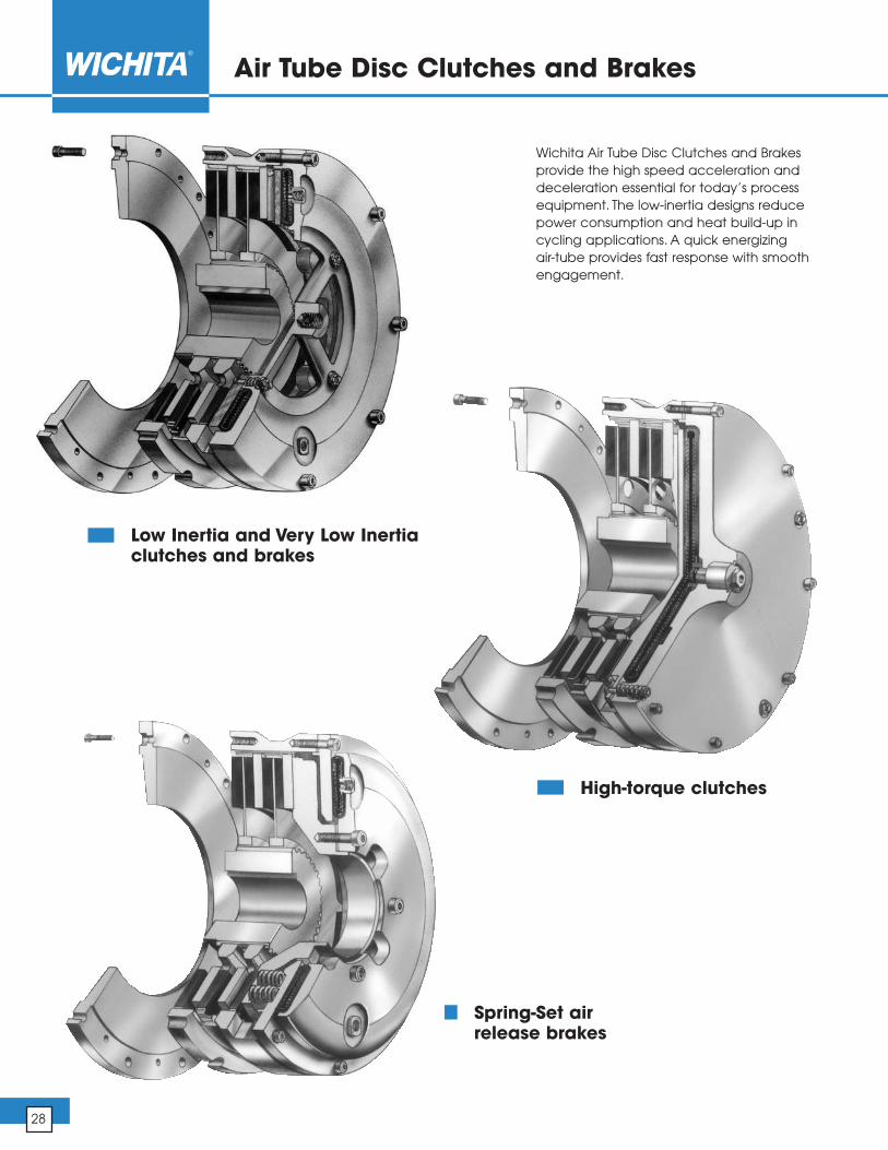
Spring-Set airrelease brakes
Wichita Air Tube Disc Clutches and Brakesprovide the high speed acceleration anddeceleration essential for today’s processequipment. The low-inertia designs reducepower consumption and heat build-up incycling applications. A quick energizing air-tube provides fast response with smoothengagement.
Low Inertia and Very Low Inertiaclutches and brakes
High-torque clutches
29
A
B
C
D
E
F
G
H
Low inertia
Clutch
Brake
Very low inertia
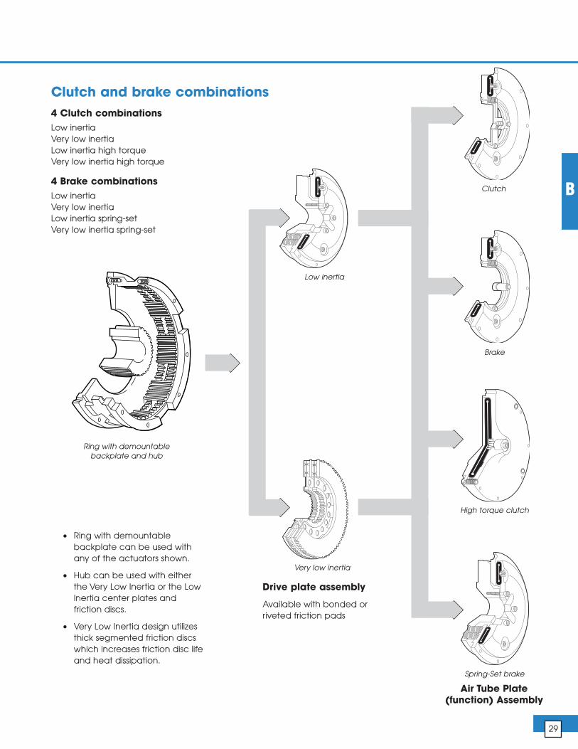
Drive plate assembly
Available with bonded orriveted friction pads
Spring-Set brake
High torque clutch
Ring with demountable backplate and hub
Clutch and brake combinations4 Clutch combinationsLow inertiaVery low inertiaLow inertia high torqueVery low inertia high torque
4 Brake combinationsLow inertiaVery low inertiaLow inertia spring-setVery low inertia spring-set
Air Tube Plate (function) Assembly
• Ring with demountablebackplate can be used withany of the actuators shown.
• Hub can be used with eitherthe Very Low Inertia or the LowInertia center plates andfriction discs.
• Very Low Inertia design utilizesthick segmented friction discswhich increases friction disc lifeand heat dissipation.
30
Air Tube Disc Clutches and Brakes
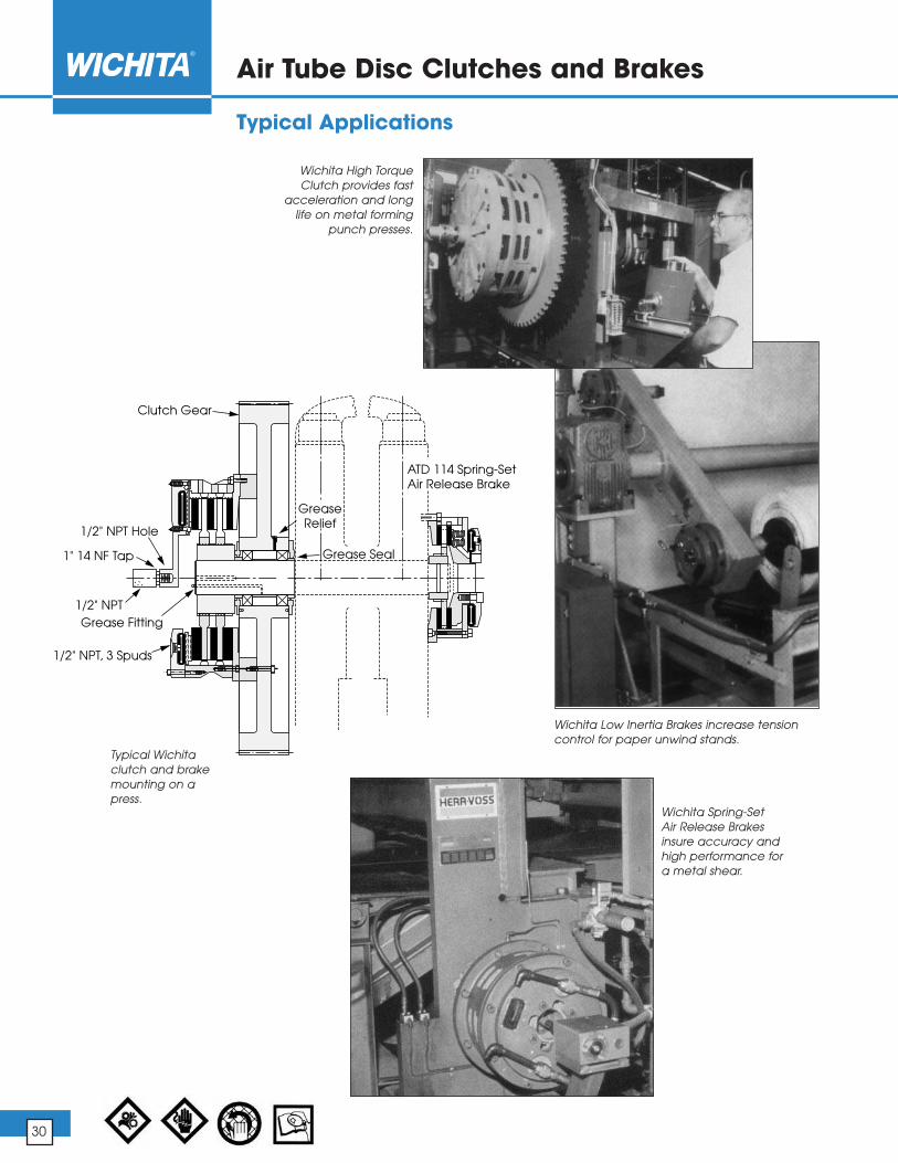
Wichita High TorqueClutch provides fast
acceleration and longlife on metal forming
punch presses.
Wichita Spring-Set Air Release Brakes insure accuracy andhigh performance for a metal shear.
Typical Applications
Wichita Low Inertia Brakes increase tensioncontrol for paper unwind stands.
ATD 114 Spring-SetAir Release Brake
GreaseRelief
Grease Seal
Grease Fitting
1/2" NPT, 3 Spuds
1/2" NPT
1" 14 NF Tap
1/2" NPT Hole
Clutch Gear
Typical Wichitaclutch and brakemounting on apress.
31
A
B
C
D
E
F
G
H
Field of Application Group A Group B Group C Group D
Pumps Centrifugal Reciprocating compressors Reciprocating compressorscompressors over 2 cylinders, one or two cylinders
centrifugal fans & blowers
Agitators Liquid Semi-solid Solids
Brick Brick press, extruder, pug millmanufacturing
Canning & bottling machine Bottle-can feeders, filling, mixers
Engine driven equipment Crane, hoist, engine Crowd
Grinding mills Ball-rod-sag-pebble Crushers, shakers
Lumber processing Yarder Carriages, conveyers Chipper, logger
Marine Propulsion clutch CP wheel Shaft brakes, propulsionreversing type, anchor winch
Bulk material Conveyors evenly loaded, Feeders Elevatorshandling line shaft evenly loaded
Metal production & Coilers, slitters, press brake, Draw bench, rolling mill, Hammer mill, formingmetalforming non-geared press, geared press shear, back geared press, press, forging press,
deep draw press, transfer header press, knuckle presspress, toggle press
Paper industry dryer Fourdrinier to 500 FPM, Fourdrinier to 1800 RPMsections & calenders paper mill plane & press selections, calendersConsult factory smoothing press & dryers
Petroleum Drilling & service rig master Mud pumps,production clutches, compound clutches, PTO clutches
rotary, drum
Rubber Transfer machines Banberry mixer, drum mixer, Centrifugemanufacturing evenly loaded extruder, calender
Application GuidelinesThis chart gives application factorsranging from light duty (the A group)to extra heavy duty (the D group).
After initial usage is determined, see
Application FactorsClutch sizes are affected by thefollowing variables:
1. Machines that operate undersmooth loads require smallerclutches. These machines aredriven by either multi-cylinder highspeed engines or electric motorswith reduced starting current.
2. Drives that require high startingcurrent motors will require clutcheswith sufficient torque to preventexcessive slipping while starting.
3. Starting torque may be high,which requires a fast clutchresponse time to transmit therequired torque or extendedclutch slip time is required toprotect the prime mover.
“Selection Requirements” to completethe selection process. The inflation andexhaust time should also be checkedto insure proper response.
4. Starting torques may be very lowcompared to the normal torque,which may result in the clutch notbeing fully pressurized prior to thetime of full torque requirement. Thiswill cause the clutch to overheatfrom slippage. Clutch inflation timein this instance is very important.
5. Clutches on most machines aredesigned to slip prior to damagefrom shockloads. As a result, theclutch may require periodic maintenance; therefore, theclutch should be located for easyaccess in the power train.Clutches should also be locatedfor maximum cooling air. In
instances where this is not possi-ble, forced air cooling may benecessary for extended clutch life.
6. Safe clutch operating speedsshould be maintained in productdesign.
Maximum Clutch Contact VelocityFPM Material
6,000 (Recommended cast iron9,000 upper limit for slip) ductile iron12,000 steel
Dynamic balancing recommendedwhen peripheral speeds exceed 3500 fpm. The maximum speedsshown are safe operating speedsbased on years of Wichita testing.Please do not exceed these limits.
32
Air Tube Disc Clutches and Brakes
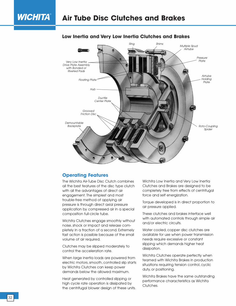
Low Inertia and Very Low Inertia Clutches and Brakes
AirtubeHolding
Plate
Ring ShimsMultiple Spud
Airtube
PressurePlate
Roto-CouplingSpider
DemountableBackplate
GroovedFriction Disc
DuctileCenter Plate
Hub
Floating Plate
Very Low InertiaDrive Plate Assembly
with Bonded or Riveted Pads
Operating FeaturesThe Wichita Air-Tube Disc Clutch combinesall the best features of the disc type clutchwith all the advantages of direct airengagement. The simplest and mosttrouble-free method of applying airpressure is through direct axial pressure application by compressed air in a specialcomposition full-circle tube.
Wichita Clutches engage smoothly withoutnoise, shock or impact and release com-pletely in a fraction of a second. Extremelyfast action is possible because of the smallvolume of air required.
Clutches may be slipped moderately tocontrol the acceleration rate.
When large inertia loads are powered fromelectric motors, smooth, controlled slip startsby Wichita Clutches can keep powerdemands below the allowed maximum.
Heat generated by controlled slipping orhigh cycle rate operation is dissipated bythe centrifugal blower design of these units.
Wichita Low Inertia and Very Low InertiaClutches and Brakes are designed to becompletely free from effects of centrifugalforce and self energization.
Torque developed is in direct proportion toair pressure applied.
These clutches and brakes interface wellwith automated controls through simple airand/or electric circuits.
Water cooled, copper disc clutches areavailable for use when power transmissionneeds require excessive or constantslipping which demands higher heat dissipation.
Wichita Clutches operate perfectly whenteamed with Wichita Brakes in productionsituations requiring tension control, cyclicduty, or positioning.
Wichita Brakes have the same outstandingperformance characteristics as WichitaClutches.
33
A
B
C
D
E
F
G
H
Selection RequirementsThe selection of a Low Inertia Brake is based on:
1. Torque required to stop a load.
2. Friction area necessary to absorbrotational energy.
3. Contact velocity of rotating discs.
4. Maximum bore capacity of unit.
Selection exampleTo properly select a Low Inertia Brake for a controlled deceleration application, thefollowing information is needed:
Speed . . . . . . . . . . . . . . . . . 750 rpmShaft Dia. . . . . . . . . . . . . . . 5 In.Inertia to Stop . . . . . . . . . . . 2,473 lb.ft.2
Stop Time . . . . . . . . . . . . . . 5 Sec.Air Pressure Available . . . . . 80 psi
CalculationsAvg. hp = WR2 X (rpm)2
3.2 x 10⁶ x Stop Time
= 2,473 X (750)2
3.2 x 106 x 5 Sec. = 87 HP
Swept Avg. hpFriction = hp absorption rate for 5 seconds Area (see page 160)
= 87 hp = 202 in.2
0.43
Torque = WR2 x rpm25.5 x Stop Time
= 2.473 x 75025.5 x 5
= 14,547 lb.in.
Using the above calculations, consult theLow Inertia Specifications Chart onpages 34 and 35.
SummaryAs calculated, the torque required to stopthe load in 5 seconds is 14,547 lb.in. WichitaLow Inertia Brakes are rated at 100 psi. Thisapplication has only 80 psi available.
To determine the torque rating of a LowInertia brake at 80 psi apply the followingformula:
Application: Torque for a Low Inertia Brake
= Torque X Catalog Rated PressureAvailable Air Pressure
= 14,547 X = 18,183 lb.in.
Consult pages 34 and 35 for clutch andbrake specifications. A Low Inertia model114 Brake produces 27,625 lb.in. torque at100 psi. However, the bore capacity is 4.125 inches. This application requires a 5 in. bore. Therefore, a Low Inertia 118 is to be investigated.
Catalog Torque Rating = 64,500 lb.in@ 100 psi
Maximum Bore Capacity = 5.25 in.Catalog Swept Friction Area = 264 in.2
Calculations show this application needs atleast 202 In.2 to absorb the heat.
All of these ratings are acceptable for thegiven application data.
Next, check contact velocity of rotatingdiscs.
= Diameter of centerplate X rpm3.82
= 18" X 7503.82
= 3,534 fpm
Standard material is sufficient up to 6,000fpm (see page 31). Balancing isrecommended above 3,500 fpm.
Therefore, a Low Inertia ATD-118 brake is the optimum choice for this application.
A Spring-Set Air Release Brake is also available (see page 54).
Note:This application example is for preliminarysizing only. Contact a Wichita Sales Engineeror the factory for final selection.
10080
34
Air Tube Disc Clutches and Brakes
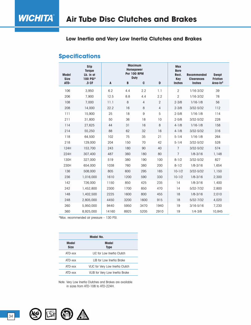
SpecificationsMaximum
HorsepowerPer 100 RPM
Duty
Slip MaxTorque Bore
Model Lb. in at Rect. Recommended SweptSize 100 PSI* Key Clearances FrictionATD- .3 CF A B C D Inches Inches Area-In2
106 3,950 6.2 4.4 2.2 1.1 2 1/16-3/32 39
206 7,900 12.5 8.8 4.4 2.2 2 1/16-3/32 78
108 7,000 11.1 8 4 2 2-3/8 1/16-1/8 56
208 14,000 22.2 16 8 4 2-3/8 3/32-5/32 112
111 15,900 25 18 9 5 2-5/8 1/16-1/8 114
211 31,800 50 36 18 10 2-5/8 3/32-5/32 228
114 27,625 44 31 16 8 4-1/8 1/16-1/8 158
214 55,250 88 62 32 16 4-1/8 3/32-5/32 316
118 64,500 102 75 35 21 5-1/4 1/16-1/8 264
218 129,000 204 150 70 42 5-1/4 3/32-5/32 528
124H 153,700 243 180 90 40 7 3/32-5/32 574
224H 307,400 487 360 180 80 7 1/8-3/16 1,148
130H 327,000 519 380 190 100 8-1/2 3/32-5/32 827
230H 654,000 1038 760 380 200 8-1/2 1/8-3/16 1,654
136 508,000 805 600 295 165 10-1/2 3/32-5/32 1,150
236 1,016,000 1610 1200 590 330 10-1/2 1/8-3/16 2,300
142 726,000 1150 850 425 235 14 1/8-3/16 1,400
242 1,452,800 2300 1700 850 470 14 5/32-7/32 2,800
148 1,402,500 2225 1600 800 455 18 1/8-3/16 2,010
248 2,805,000 4450 3200 1600 915 18 5/32-7/32 4,020
260 5,950,000 9440 5950 3470 1940 19 3/16-5/16 7,230
360 8,925,000 14160 8925 5205 2910 19 1/4-3/8 10,845
*Max. recommended air pressure – 130 PSI.
Low Inertia and Very Low Inertia Clutches and Brakes
Model No.
Model ModelSize Type
ATD-xxx LIC for Low Inertia Clutch
ATD-xxx LIB for Low Inertia Brake
ATD-xxx VLIC for Very Low Inertia Clutch
ATD-xxx VLIB for Very Low Inertia Brake
Note: Very Low Inertia Clutches and Brakes are availablein sizes from ATD-108 to ATD-224H.
35
A
B
C
D
E
F
G
H
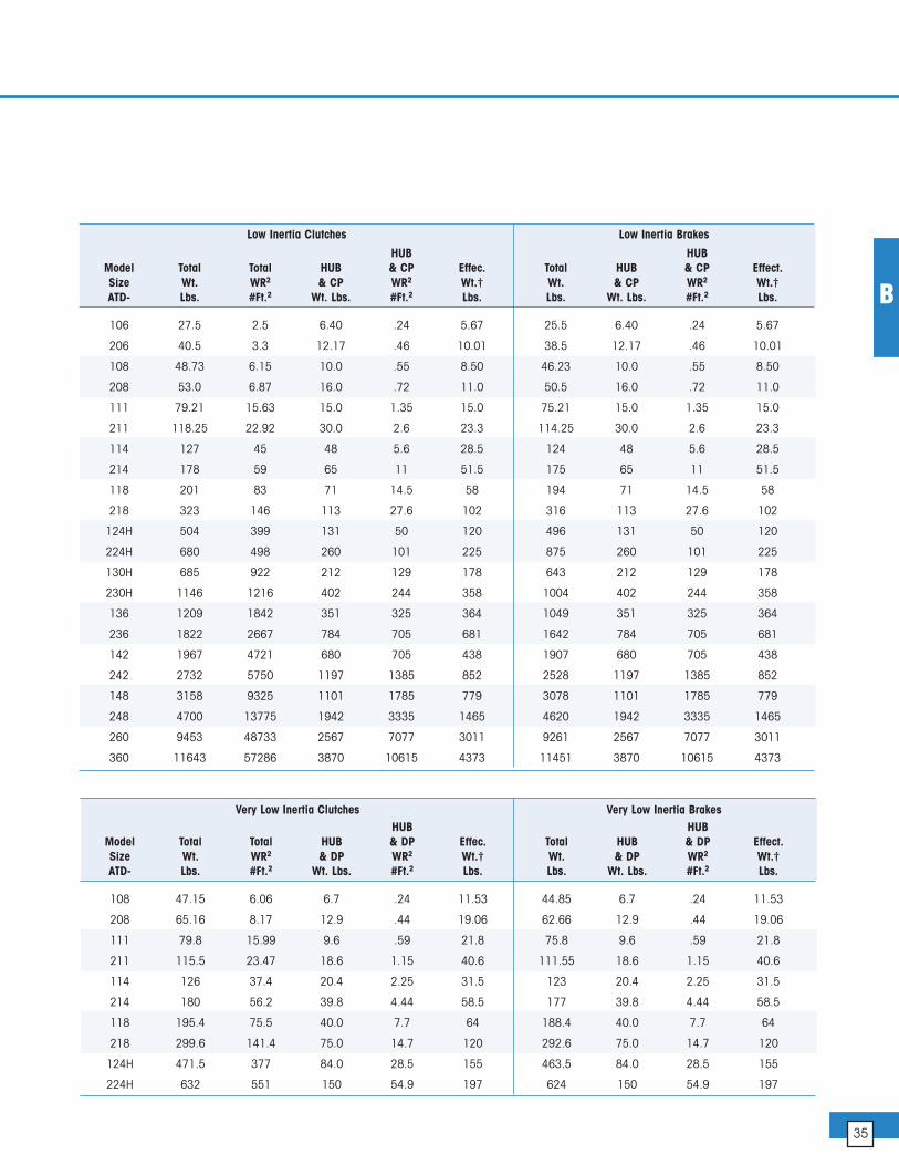
HUB HUBModel Total Total HUB & CP Effec. Total HUB & CP Effect.Size Wt. WR2 & CP WR2 Wt.† Wt. & CP WR2 Wt.†ATD- Lbs. #Ft.2 Wt. Lbs. #Ft.2 Lbs. Lbs. Wt. Lbs. #Ft.2 Lbs.
106 27.5 2.5 6.40 .24 5.67 25.5 6.40 .24 5.67
206 40.5 3.3 12.17 .46 10.01 38.5 12.17 .46 10.01
108 48.73 6.15 10.0 .55 8.50 46.23 10.0 .55 8.50
208 53.0 6.87 16.0 .72 11.0 50.5 16.0 .72 11.0
111 79.21 15.63 15.0 1.35 15.0 75.21 15.0 1.35 15.0
211 118.25 22.92 30.0 2.6 23.3 114.25 30.0 2.6 23.3
114 127 45 48 5.6 28.5 124 48 5.6 28.5
214 178 59 65 11 51.5 175 65 11 51.5
118 201 83 71 14.5 58 194 71 14.5 58
218 323 146 113 27.6 102 316 113 27.6 102
124H 504 399 131 50 120 496 131 50 120
224H 680 498 260 101 225 875 260 101 225
130H 685 922 212 129 178 643 212 129 178
230H 1146 1216 402 244 358 1004 402 244 358
136 1209 1842 351 325 364 1049 351 325 364
236 1822 2667 784 705 681 1642 784 705 681
142 1967 4721 680 705 438 1907 680 705 438
242 2732 5750 1197 1385 852 2528 1197 1385 852
148 3158 9325 1101 1785 779 3078 1101 1785 779
248 4700 13775 1942 3335 1465 4620 1942 3335 1465
260 9453 48733 2567 7077 3011 9261 2567 7077 3011
360 11643 57286 3870 10615 4373 11451 3870 10615 4373
Low Inertia Clutches Low Inertia Brakes
HUB HUBModel Total Total HUB & DP Effec. Total HUB & DP Effect.Size Wt. WR2 & DP WR2 Wt.† Wt. & DP WR2 Wt.†ATD- Lbs. #Ft.2 Wt. Lbs. #Ft.2 Lbs. Lbs. Wt. Lbs. #Ft.2 Lbs.
108 47.15 6.06 6.7 .24 11.53 44.85 6.7 .24 11.53
208 65.16 8.17 12.9 .44 19.06 62.66 12.9 .44 19.06
111 79.8 15.99 9.6 .59 21.8 75.8 9.6 .59 21.8
211 115.5 23.47 18.6 1.15 40.6 111.55 18.6 1.15 40.6
114 126 37.4 20.4 2.25 31.5 123 20.4 2.25 31.5
214 180 56.2 39.8 4.44 58.5 177 39.8 4.44 58.5
118 195.4 75.5 40.0 7.7 64 188.4 40.0 7.7 64
218 299.6 141.4 75.0 14.7 120 292.6 75.0 14.7 120
124H 471.5 377 84.0 28.5 155 463.5 84.0 28.5 155
224H 632 551 150 54.9 197 624 150 54.9 197
Very Low Inertia Clutches Very Low Inertia Brakes
36
Air Tube Disc Clutches and Brakes
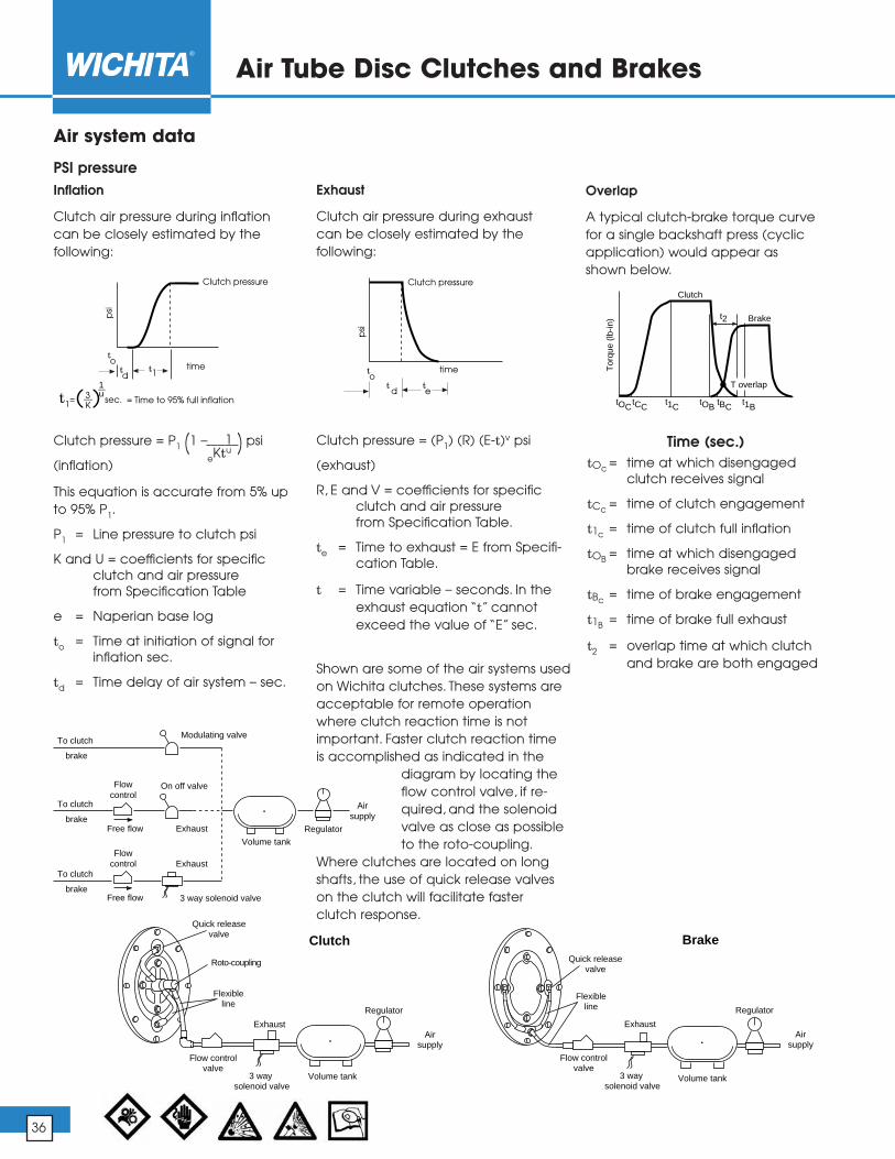
Air system data
PSI pressureInflation
Clutch air pressure during inflationcan be closely estimated by thefollowing:
Clutch pressure = P1 (1 – ) psi
(inflation)
This equation is accurate from 5% up to 95% P1.
P1 = Line pressure to clutch psi
K and U = coefficients for specificclutch and air pressurefrom Specification Table
e = Naperian base log
to = Time at initiation of signal forinflation sec.
td = Time delay of air system – sec.
Exhaust
Clutch air pressure during exhaust can be closely estimated by the following:
Clutch pressure = (P1) (R) (E-t)v psi
(exhaust)
R, E and V = coefficients for specificclutch and air pressurefrom Specification Table.
te = Time to exhaust = E from Specifi-cation Table.
t = Time variable – seconds. In theexhaust equation “t” cannotexceed the value of “E” sec.
Shown are some of the air systems usedon Wichita clutches. These systems areacceptable for remote operationwhere clutch reaction time is notimportant. Faster clutch reaction time is accomplished as indicated in the
diagram by locating theflow control valve, if re-quired, and the solenoidvalve as close as possible to the roto-coupling.
Where clutches are located on longshafts, the use of quick release valveson the clutch will facilitate faster clutch response.
Overlap
A typical clutch-brake torque curvefor a single backshaft press (cyclicapplication) would appear asshown below.
Time (sec.)tOc = time at which disengaged
clutch receives signal
tCc = time of clutch engagement
t1c = time of clutch full inflation
tOB = time at which disengagedbrake receives signal
tBc = time of brake engagement
t1B = time of brake full exhaust
t2 = overlap time at which clutchand brake are both engaged
1eKtu
To clutch
brake
To clutch
brake
To clutch
brake
Modulating valve
On off valve
Exhaust
Flowcontrol
Flowcontrol
Free flow
Free flow 3 way solenoid valve
Volume tank
Regulator
Airsupply
Exhaust
3 way solenoid valve
Volume tank
Regulator
Airsupply
Exhaust
Flow controlvalve
Clutch
Flexibleline
Quick releasevalve
Roto-coupling
3 way solenoid valve
Volume tank
Regulator
Airsupply
Exhaust
Flow controlvalve
Brake
Flexibleline
Quick releasevalve
Clutch
Brake
T overlap
Tor
que
(lb-in
)
tOCtCC t1C tOB t1BtBC
t2
psi
timet o t d
t e
Clutch pressure
psi
Clutch pressure
timet o t d
t1
t1= 3 sec.K (—)
1u—
= Time to 95% full inflation
37
A
B
C
D
E
F
G
H
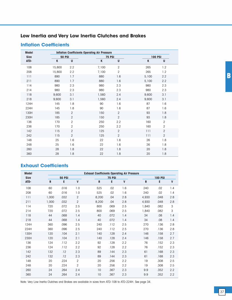
Low Inertia and Very Low Inertia Clutches and Brakes
Model Exhaust Coefficients Operating Air PressureSize 50 PSI 75 PSI 100 PSIATD- R E V R E V R E V
108 60 .016 1.0 525 .02 1.6 240 .02 1.4
208 60 .016 1.0 525 .02 1.6 240 .02 1.4
111 1,000 .032 2 8,200 .04 2.8 4,930 .048 2.8
211 1,000 .032 2 8,200 .04 2.8 4,930 .048 2.8
114 720 .072 2.5 800 .069 2.5 1,840 .082 3
214 720 .072 2.5 800 .069 2.5 1,840 .082 3
118 44 .068 1.4 40 .072 1.4 34 .08 1.4
218 44 .068 1.4 40 .072 1.4 34 .08 1.4
124H 360 .096 2.5 240 .112 2.5 270 .136 2.8
224H 360 .096 2.5 240 .112 2.5 270 .136 2.8
130H 120 .104 2.1 140 .128 2.4 146 .158 2.7
230H 120 .104 2.1 140 .128 2.4 146 .158 2.7
136 124 .112 2.2 92 .128 2.2 76 .152 2.3
236 124 .112 2.2 92 .128 2.2 76 .152 2.3
142 132 .12 2.3 89 .144 2.3 61 .168 2.3
242 132 .12 2.3 89 .144 2.3 61 .168 2.3
148 20 .224 2 20 .256 2.2 19 .308 2.5
248 20 .224 2 20 .256 2.2 19 .308 2.5
260 24 .264 2.4 10 .367 2.3 9.9 .352 2.2
360 24 .264 2.4 10 .367 2.3 9.9 .352 2.2
Exhaust Coefficients
Model Inflation Coefficients Operating Air PressureSize 50 PSI 75 PSI 100 PSIATD- K U K U K U
108 15,800 2.2 7,100 2 265 1.2
208 15,800 2.2 7,100 2 265 1.2
111 890 1.7 880 1.6 5,100 2.2
211 890 1.7 880 1.6 5,100 2.2
114 980 2.3 980 2.3 980 2.3
214 980 2.3 980 2.3 980 2.3
118 9,600 3.1 1,560 2.4 9,600 3.1
218 9,600 3.1 1,560 2.4 9,600 3.1
124H 145 1.8 90 1.6 87 1.6
224H 145 1.8 90 1.6 87 1.6
130H 185 2 150 2 93 1.8
230H 185 2 150 2 93 1.8
136 170 2 250 2.2 160 2
236 170 2 250 2.2 160 2
142 115 2 125 2 111 2
242 115 2 125 2 111 2
148 25 1.6 22 1.6 26 1.8
248 25 1.6 22 1.6 26 1.8
260 28 1.8 22 1.8 20 1.8
360 28 1.8 22 1.8 20 1.8
Inflation Coefficients
Note: Very Low Inertia Clutches and Brakes are available in sizes from ATD-108 to ATD-224H. See page 34.
39
A
B
C
D
E
F
G
H
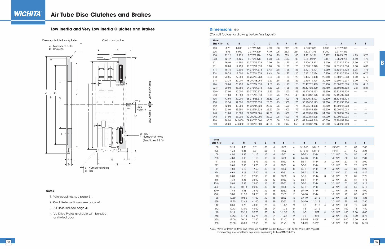
Dimensions (in)
(Consult factory for drawing before final layout.)
ModelSize ATD- A B C D E F G H I J K L
106 8.75 8.000 7.377/7.379 4.19 .06 .562 .69 7.373/7.375 8.000 7.377/7.379 — —
206 8.75 8.000 7.377/7.379 4.19 .06 .562 .69 7.373/7.375 8.000 7.377/7.379 — —
108 12.12 11.125 8.375/8.378 5.38 .25 .875 1.00 9.281/9.284 10.187 9.285/9.288 4.25 3.75
208 12.12 11.125 8.375/8.378 5.38 .25 .875 1.00 9.281/9.284 10.187 9.285/9.288 5.50 4.75
111 16.00 14.750 11.375/11.378 7.00 .38 1.125 1.25 12.370/12.373 13.500 12.375/12.378 5.50 3.75
211 16.00 14.750 11.375/11.378 7.00 .38 1.125 1.25 12.370/12.373 13.500 12.375/12.378 7.38 5.63
114 18.75 17.500 14.375/14.378 9.43 .38 1.125 1.25 15.121/15.124 16.250 15.125/15.128 6.25 4.75
214 18.75 17.500 14.375/14.378 9.43 .38 1.125 1.25 15.121/15.124 16.250 15.125/15.128 8.25 6.75
118 23.25 22.000 18.250/18.253 12.50 .38 1.125 1.25 19.495/19.498 20.750 19.500/19.503 6.69 5.19
218 23.25 22.000 18.250/18.253 12.50 .38 1.125 1.25 19.495/19.498 20.750 19.500/19.503 9.00 7.50
124H 30.00 28.750 24.375/24.378 14.50 .25 1.125 1.25 25.497/25.499 26.750 25.500/25.503 7.63 6.13
224H 30.00 28.750 24.375/24.378 14.50 .25 1.125 1.25 25.497/25.499 26.750 25.500/25.503 10.31 8.81
130H 37.00 35.500 30.375/30.378 19.25 .25 1.250 1.43 32.118/32.123 33.250 32.125/32.128 — —
230H 37.00 35.500 30.375/30.378 19.25 .25 1.250 1.43 32.118/32.123 33.250 32.125/32.128 — —
136 43.50 42.000 36.375/36.378 23.63 .25 1.500 1.75 38.120/38.123 39.500 38.125/38.128 — —
236 43.50 42.000 36.375/36.378 23.63 .25 1.500 1.75 38.120/38.123 39.500 38.125/38.128 — —
142 52.00 49.250 44.625/44.628 29.50 .25 1.500 1.75 44.995/44.998 46.500 45.000/45.003 — —
242 52.00 49.250 44.625/44.628 29.50 .25 1.500 1.75 44.995/44.998 46.500 45.000/45.003 — —
148 61.00 58.000 52.000/52.005 32.00 .25 1.500 1.75 51.993/51.998 54.000 52.000/52.005 — —
248 61.00 58.000 52.000/52.005 32.00 .25 1.500 1.75 51.993/51.998 54.000 52.000/52.005 — —
260 78.50 74.5000 59.990/60.000 35.50 .38 3.25 3.50 62.740/62.745 66.500 62.750/62.760 — —
360 78.50 74.5000 59.990/60.000 35.50 .38 3.25 3.50 62.740/62.745 66.500 62.750/62.760 — —
ModelSize ATD- M N O Z a b c d e f g h j k
106 3.19 4.63 8.81 .06 4 11/32 4 5/16-18 5/8-18 2 1/4"NPT .31 .69 2.00
206 4.38 5.81 8.81 .06 4 11/32 4 5/16-18 5/8-18 1/4"NPT .31 .69 3.25
108 4.50 4.38 11.13 .13 6 17/32 6 1/2-13 1"-14 2 1/2" NPT .50 .50 1.50
208 4.88 6.63 11.13 .13 6 17/32 6 1/2-13 1"-14 1/2" NPT .50 .50 2.87
111 3.88 5.63 14.75 .13 6 21/32 6 5/8-11 1"-14 2 1/2" NPT .63 .75 2.00
211 5.63 7.38 14.75 .13 6 21/32 6 5/8-11 1"-14 1/2" NPT .63 .75 3.75
114 4.63 6.13 17.50 .13 8 21/32 8 5/8-11 1"-14 2 1/2" NPT .63 .88 2.25
214 6.63 8.13 17.50 .13 8 21/32 8 5/8-11 1"-14 1/2" NPT .63 .88 4.25
118 5.63 7.13 22.00 .13 12 21/32 12 5/8-11 1"-14 3 1/2" NPT .63 .81 2.75
218 7.38 8.88 22.00 .13 12 21/32 12 5/8-11 1"-14 1/2" NPT .63 .81 4.75
124H 5.88 7.38 29.00 .13 12 21/32 12 5/8-11 1"-14 3 1/2" NPT .63 .56 3.13
224H 8.75 10.13 29.00 .13 12 21/32 12 5/8-11 1"-14 1/2" NPT .63 .56 5.13
130H 7.88 9.38 34.75 .19 18 25/32 18 3/4-10 1"-14 4 1/2" NPT .75 .88 4.00
230H 9.88 11.38 34.75 .19 18 25/32 18 3/4-10 1"-14 1/2" NPT .75 .88 6.25
136 10.69 10.50 41.00 .19 18 25/32 18 3/4-10 1 1/2-12 4 1/2" NPT .75 .88 4.25
236 11.75 12.44 41.00 .19 18 25/32 18 3/4-10 1 1/2-12 1/2" NPT .75 .88 7.50
142 8.38 9.25 49.00 .25 24 1-1/32 24 1-8 1 1/2-12 4 1/2" NPT 1.00 .75 5.62
242 12.13 13.00 49.00 .25 24 1-1/32 24 1-8 1 1/2-12 1/2" NPT 1.00 .75 7.50
148 9.13 13.13 56.75 .25 24 1-1/32 24 1-8 1" NPT 4 1/2" NPT 1.00 1.00 6.00
248 13.43 17.43 56.75 .25 24 1-1/32 24 1-8 1" NPT 1/2" NPT 1.00 1.00 8.75
260 18.00 20.38 70.50 .25 24 2" NC 24 2-4-1/2 2-1/2" 6 1/2" NPT 2.00 1.00 9.37
360 23.00 25.00 70.50 .25 24 2" NC 24 2-4-1/2 2-1/2" 1/2" NPT 2.00 1.00 14.13
Notes: Very Low Inertia Clutches and Brakes are available in sizes from ATD-108 to ATD-224H. See page 34.For mounting, use socket head cap screws conforming to the ASTM-574-97a.
38
Air Tube Disc Clutches and Brakes
Low Inertia and Very Low Inertia Clutches and Brakes
Notes:
1. Roto-couplings, see page 61.
2. Quick Release Valves, see page 61.
3. Air Hose Kits, see page 41.
4. VLI Drive Plates available with bonded or riveted pads.
A
B
C
D
E
F
G
H
M
N
O
h
Z
I
J
k e
(See Note 1)
j
g - Tapf - Number of holes (See Notes 2 & 3)
K
L
a - Number of holesb - Hole size
Low
ine
rtia
Ve
ry lo
w in
ert
ia
c - Number of holesd - Tap
Demountable backplate Clutch or brake
40
Air Tube Disc Clutches and Brakes
10
11
12
13
14
2019
3
2
4
1
6
7
6
7
8
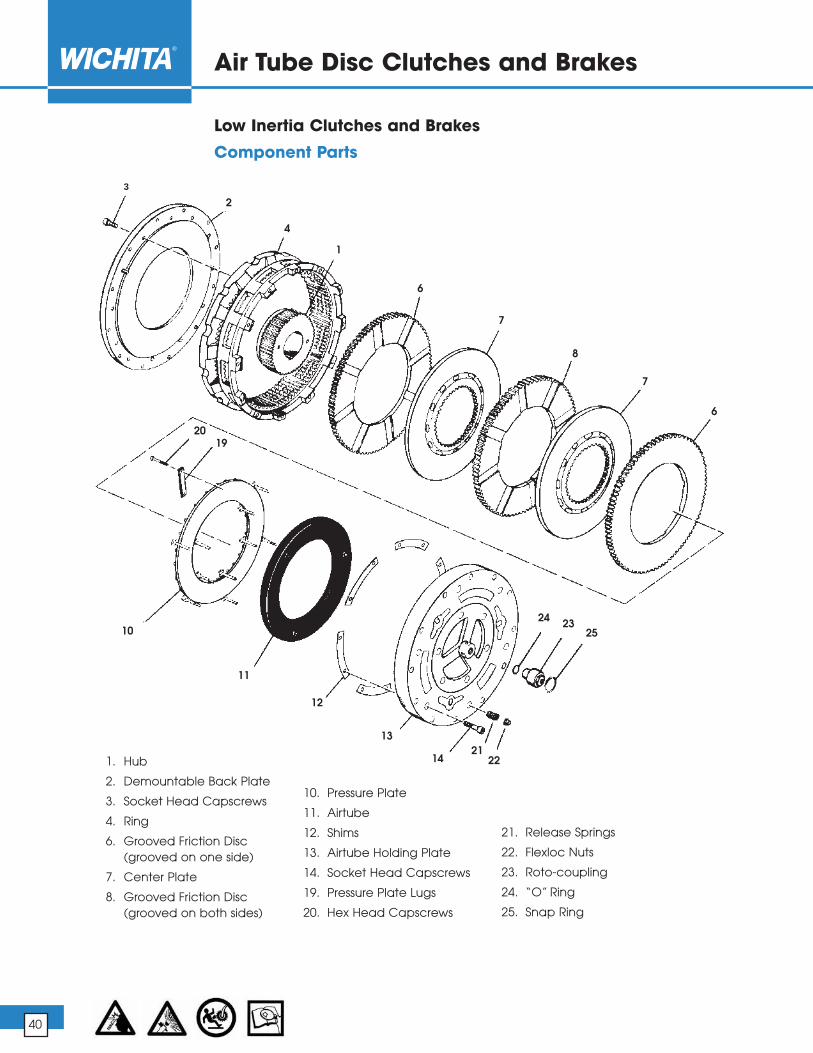
Low Inertia Clutches and Brakes
Component Parts
24 2325
21221. Hub
2. Demountable Back Plate
3. Socket Head Capscrews
4. Ring
6. Grooved Friction Disc(grooved on one side)
7. Center Plate
8. Grooved Friction Disc(grooved on both sides)
10. Pressure Plate
11. Airtube
12. Shims
13. Airtube Holding Plate
14. Socket Head Capscrews
19. Pressure Plate Lugs
20. Hex Head Capscrews
21. Release Springs
22. Flexloc Nuts
23. Roto-coupling
24. “O” Ring
25. Snap Ring
41
A
B
C
D
E
F
G
H
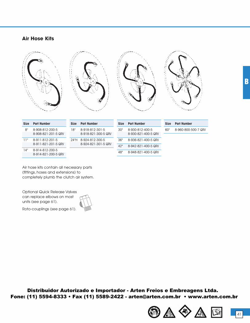
Air Hose Kits
Air hose kits contain all necessary parts(fittings, hoses and extensions) to completely plumb the clutch air system.
Optional Quick Release Valves can replace elbows on most units (see page 61).
Roto-couplings (see page 61).
Size Part Number
8" 8-908-812-200-58-908-821-201-5 QRV
11" 8-911-812-201-58-911-821-201-5 QRV
14" 8-914-812-200-58-914-821-200-5 QRV
Size Part Number
18" 8-918-812-301-58-918-821-300-5 QRV
24"H 8-924-812-300-58-924-821-301-5 QRV
Size Part Number
30" 8-930-812-400-58-930-821-400-5 QRV
36" 8-936-821-400-5 QRV
42" 8-942-821-400-5 QRV
48" 8-948-821-400-5 QRV
Size Part Number
60" 8-960-800-500-7 QRV
Distribuidor Autorizado e Importador - Arten Freios e Embreagens Ltda.Fone: (11) 5594-8333 • Fax (11) 5589-2422 - [email protected] • www.arten.com.br