Embed Size (px)
Citation preview

© 2004 – 2010 9000 Virginia Manor Rd Ste. 290, Beltsville MD 20705 | 301-474-0607 | www.dfrsolutions.com
Coatings and Pottings:A Critical Update
Webinar – February 16, 2017
Presented by: Greg Caswell

9000 Virginia Manor Rd Ste. 290, Beltsville MD 20705 | 301-474-0607 | www.dfrsolutions.com2
Abstract
o Conformal coatings and potting materials continue to create issues for the electronics industry. This webinar will dig deeper into the failure modes of these materials, specifically issues with Coefficient of Thermal Expansion (CTE), delamination, cracking, de-wetting, pinholes/bubbles and orange peel issues with conformal coatings and what mitigation techniques are available. Similarly, this webinar will look at the failure modes of potting materials, (e.g Glass Transition Temperature (Tg), PCB warpage, the effects of improper curing and potential methods for correcting these situations.
o Finally, advances in superhydrophobic materials will be addressed to demonstrate the direction the industry is taking with respect to this topic.

9000 Virginia Manor Rd Ste. 290, Beltsville MD 20705 | 301-474-0607 | www.dfrsolutions.com
The Need for Cleaning Before
Coating or Potting

9000 Virginia Manor Rd Ste. 290, Beltsville MD 20705 | 301-474-0607 | www.dfrsolutions.com4
Contamination
o Two concerns
o Hygroscopic contaminants (discussed)
o Ionisable contaminants that are soluble in water (e.g., acids, salts)
o Ionic contaminants of greatest concern
o Primarily anions; especially halides (chlorides and bromides)
o Chemically aggressive due to chemical structure
o Very common in electronics manufacturing process
o Decreases pH; few metal ions found in dendrites are soluble at mid to high pH. Cu dendrites require pH less than 5 to form.
o Silver(I) ions are soluble at higher pH; reason it is one of easiest to form dendrites.
o Cations primarily assist in the identifying the source of anions
o Example: Cl with K suggests KCl (salt from human sweat)
9000 Virginia Manor Rd Ste. 290, Beltsville MD 20705 | 301-474-0607 | www.dfrsolutions.com5
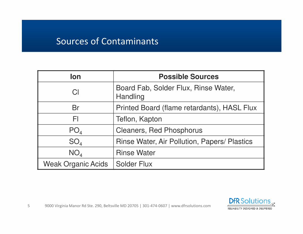
Sources of Contaminants
Ion Possible Sources
ClBoard Fab, Solder Flux, Rinse Water, Handling
Br Printed Board (flame retardants), HASL Flux
Fl Teflon, Kapton
PO4 Cleaners, Red Phosphorus
SO4 Rinse Water, Air Pollution, Papers/ Plastics
NO4 Rinse Water
Weak Organic Acids Solder Flux

9000 Virginia Manor Rd Ste. 290, Beltsville MD 20705 | 301-474-0607 | www.dfrsolutions.com6
PCB Contaminants (examples)
o Etching
o Chloride-based: Alkaline ammonia (ammonium chloride), cupric chloride, ferric chloride, persulfates (sometimes formulated with mercuric chloride)
o Other: Peroxide-sulfuric acid
o Neutralizer
o Hydrochloric acid
o Cleaning and degreasing
o Hydrochloric acid, chlorinated solvents (rare)
o Photoresist stripping
o methylene chloride as a solvent
o Oxide
o Sodium chlorite
o Electroless plating
o Sodium hypochlorite (in potassium permanganate)
o Palladium chlorides (catalyst)

9000 Virginia Manor Rd Ste. 290, Beltsville MD 20705 | 301-474-0607 | www.dfrsolutions.com7
Source of Contaminants: Fluxes
o Chemicals used for preparing metal surfaces for soldering
o High molecular weight chemistries
o Slightly acidic
o Optimum behavior
o Maximum activity during reflow; minimum activity after reflow
o Difficult balancing act
o Flux nomenclature
o Rosin only (RO)
o Rosin, mildly activated (RMA)
o Rosin activated
o Water soluble
o Low residue (no-clean)

9000 Virginia Manor Rd Ste. 290, Beltsville MD 20705 | 301-474-0607 | www.dfrsolutions.com8
J-STD-004 Flux Classification

9000 Virginia Manor Rd Ste. 290, Beltsville MD 20705 | 301-474-0607 | www.dfrsolutions.com
Handling / Storage / Environment
o Handling
o Salts from human contact (KCl and NaCl)
o Storage
o Cleaning chemicals
o Outgassing
o Polymeric materials
o Use Environment
o Dust
o Evaporated sea water
o Industrial pollutants

9000 Virginia Manor Rd Ste. 290, Beltsville MD 20705 | 301-474-0607 | www.dfrsolutions.com
Handling / Sweat
o Composition of dissolved salts in water
o Can include other biological molecules.
o Main constituents, after the solvent (water),
o Chloride, sodium, potassium, calcium, magnesium, lactate, and urea.
o Chloride and sodium dominate.
o To a lesser but highly variable extent, iron, copper, urocanate (and the
parent molecule histidine), and other metals, proteins, and enzymes
are also present.
o The main concern regarding sweat is as a source of chloride

9000 Virginia Manor Rd Ste. 290, Beltsville MD 20705 | 301-474-0607 | www.dfrsolutions.com11
Conformal Coating
o Conformal coating is applied to circuit cards to provide a dielectric layer on an electronic board. This layer functions as a membrane between the board and the environment. With this coating in place, the circuit card can withstand more moisture by increasing the surface resistance or surface insulation resistance (SIR). With a higher SIR board, the risk of problems such as cross talk, electrical leakage, intermittent signal losses, and shorting is reduced.
o This reduction in moisture will also help to reduce metallic growth called dendrites and corrosion or oxidation. Conformal coating will also serve to shield a circuit card from dust, dirt and pollutants that can carry moisture and may be acidic or alkaline.

9000 Virginia Manor Rd Ste. 290, Beltsville MD 20705 | 301-474-0607 | www.dfrsolutions.com12
Summary of Conventional Materials
o Rework
procedures
for
Paralyne
now exist

9000 Virginia Manor Rd Ste. 290, Beltsville MD 20705 | 301-474-0607 | www.dfrsolutions.com13
Theoretical Information
o The conformal coating material can be applied by
brushing, spraying or dipping. Or, due to the
increasing complexities of electronic circuit board
assemblies being designed and with the 'process
window' becoming smaller and smaller, by selectively
coating via robot.

9000 Virginia Manor Rd Ste. 290, Beltsville MD 20705 | 301-474-0607 | www.dfrsolutions.com14
o Inspection of the coating is easily accomplished using “Black Light” to expose
the surface to be inspected. The conformal coating will fluoresce. Areas that
are coated will look like snow on the surface of the PWB, while uncoated
areas look dark. This allows touch up to be performed to assure full coverage
of the product.
o Inspection Requirements are usually to IPC-610 for commercial applications
and MIL-I-45608 for military.
Inspection

9000 Virginia Manor Rd Ste. 290, Beltsville MD 20705 | 301-474-0607 | www.dfrsolutions.com15
o Methods include air, UV, thermal and moisture laden atmospheres
o Time to cure is a function of the type of coating and the application methodo Tack free, Time required, Optimum properties
o Know the Difference!!!
o If using UV curable coating you may have to have a secondary cure for material not exposed to the UV
o Max temperature during curing should be <100C
o If thermal curing is used – may require several hours of air curing to permit outgassing before entering a chamber
o Must be cured to optimum properties before any other environmental exposure
Proper Curing
9000 Virginia Manor Rd Ste. 290, Beltsville MD 20705 | 301-474-0607 | www.dfrsolutions.com16
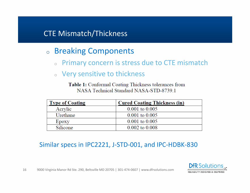
o Breaking Components
o Primary concern is stress due to CTE mismatch
o Very sensitive to thickness
CTE Mismatch/Thickness
Similar specs in IPC2221, J-STD-001, and IPC-HDBK-830

9000 Virginia Manor Rd Ste. 290, Beltsville MD 20705 | 301-474-0607 | www.dfrsolutions.com17
o Cracked Components
o Especially glass MELF Diodes
o Cracked Solder Joints
o Primarily cylindrical components
Failure Modes

9000 Virginia Manor Rd Ste. 290, Beltsville MD 20705 | 301-474-0607 | www.dfrsolutions.com18
o Dip coated assembly with BGA technology
o Passed ALT (-40C / 100C)
o Failing quickly in the field
Solder Fracture –Why?
9000 Virginia Manor Rd Ste. 290, Beltsville MD 20705 | 301-474-0607 | www.dfrsolutions.com19
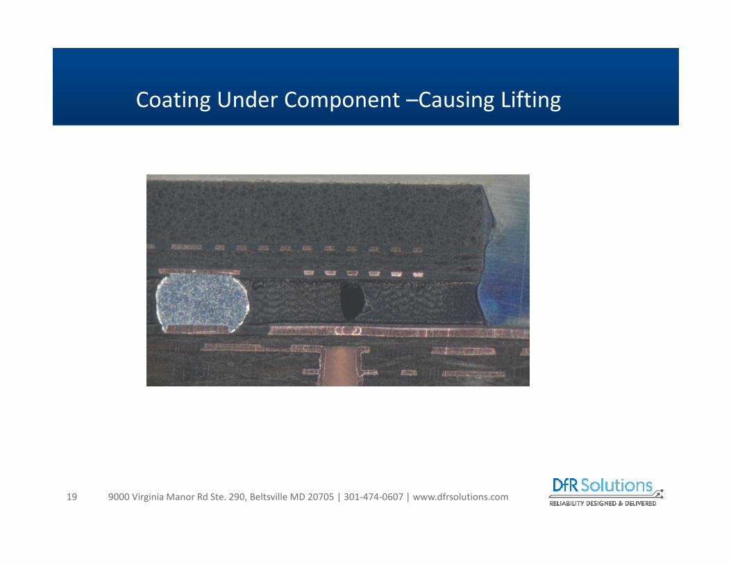
Coating Under Component –Causing Lifting

9000 Virginia Manor Rd Ste. 290, Beltsville MD 20705 | 301-474-0607 | www.dfrsolutions.com20
Tg Behavior
o Near the glass transition temperature (Tg), CTE changes more rapidly than modulus
o Changes in the CTE in polymers tend to be driven by changes in the free volume
o Changes in modulus tend to be driven by increases in translational / rotational movement of the polymer chains
o Increases in CTE tend to initiate before decreases in modulus because lower levels of energy (temperature) are required to increase free volume compared to increases in movement along the polymer chains
Polymer Science and Technology, Chapter 4: Thermal Transitions in Polymers,
Robert Oboigbaotor Ebewele, CRC Press, 2000
0.01
0.10
1.00
10.00
35 45 55 65 75 85 95 105
Temperature (oC)
Sto
rag
e M
od
ulu
s (
MP
a)
0
20
40
60
80
100
120
140
CT
E (p
pm
/ oC)
Storage Modulus
CTE
High stresses generated due to CTE increase before modulus decrease

9000 Virginia Manor Rd Ste. 290, Beltsville MD 20705 | 301-474-0607 | www.dfrsolutions.com21
Glass Transition Temperature
Tg ≈ 5 to 15°C
Coefficient of Thermal Expansion - TMA
Below Tg CTE – 170 ppm/°C
Above Tg : CTE – 340 ppm/°C
Acrylic conformal coating

9000 Virginia Manor Rd Ste. 290, Beltsville MD 20705 | 301-474-0607 | www.dfrsolutions.com
Sulfur Attack of Coated Hybrid
o Silicone coating,
ceramic hybrid
o Used in industrial controls
o Customer reported failures
after 12 to 36 months in the field
o X-ray identified several separations
‘Good’
hybrid
‘Bad’
hybrid
Visual inspection revealed black corrosion product throughout the hybrid
Most severe in areas with no solder or solder mask covering silver thick film tracesAttack through the solder mask in some locations
9000 Virginia Manor Rd Ste. 290, Beltsville MD 20705 | 301-474-0607 | www.dfrsolutions.com
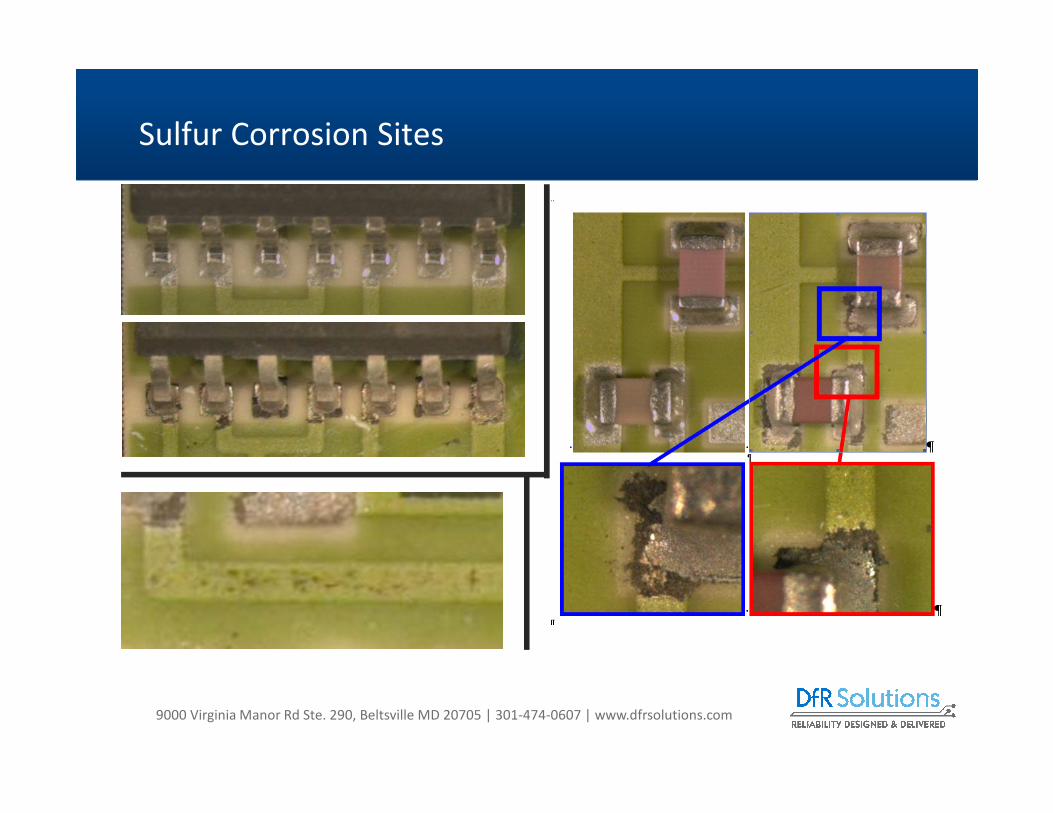
Sulfur Corrosion Sites

9000 Virginia Manor Rd Ste. 290, Beltsville MD 20705 | 301-474-0607 | www.dfrsolutions.com
o Sulfur attack of silver occurs at the abutment of the glass passivation layer and the resistor termination
o Cracks or openings can allow the ingress of corrosive gases,
o Reaction with the silver to form silver sulfide (Ag2S)
o Large change in resistance
o ρAg = 10-8 ohm-m; ρAg2S = 10 ohm-m
o Up 20K ohms (0.01 x 0.01 x 0.5mm)
o Manufacturers’ solutions
o Sulfur tolerant – silver alloys
o Sulfur resistant – silver replacement
SMT Resistors

9000 Virginia Manor Rd Ste. 290, Beltsville MD 20705 | 301-474-0607 | www.dfrsolutions.com25
Conformal Coating Failure Modes
o Capillary Flow is when the
conformal coating runs
away from some areas to
more favorable areas,
possibly even under BGAs
o Low viscosity of the
coating could cause
this
o Too much coating
applied
o High surface tension of
the coating From SCH Technologies – Aug 08 Technical bulletin

9000 Virginia Manor Rd Ste. 290, Beltsville MD 20705 | 301-474-0607 | www.dfrsolutions.com26
Conformal Coating Failure Modes
o Delamination is when
the conformal coating
lifts from the board
surface
o Cleanliness
o Cure cycle for coating

9000 Virginia Manor Rd Ste. 290, Beltsville MD 20705 | 301-474-0607 | www.dfrsolutions.com27
Conformal Coating Failure Modes
o Cracking of the coating can be due to a cure temperature that was too high or the cure cycle was too fast.
o Also if the conformal coating is applied too thick (>5 mils) its CTE mismatch can drive the cracks.
o Or, the operating environment is too hot or too low causing the coating to flex too much and crack
From SCH Technologies – Oct 08 Technical bulletin

9000 Virginia Manor Rd Ste. 290, Beltsville MD 20705 | 301-474-0607 | www.dfrsolutions.com28
Conformal Coating Failure Modes
o Dewetting – is when the conformal coating refuses to
adhere to the surface that is has been applied to.
o Causes can be flux residue due to no-clean flux being
used.
o HASL rinse operation not cleaning completely
o Silicone oils
o Mold release agents
o Soldering processes
o Cleaning bath contamination
From SCH Technologies – Nov 08 Technical bulletin

9000 Virginia Manor Rd Ste. 290, Beltsville MD 20705 | 301-474-0607 | www.dfrsolutions.com29
Conformal Coating Failure Modes
o Pinholes/Bubbles – trapped air under conformal coating
o Possible causes – skin over surface trapping solvents under surface
o If coating is too thick then bubbles can get trapped during
application
o Requires good adhesion to the circuit board
o Bubbles/Voids/Delam can drive micro-condensation
o Can make it electrochemical migration MORE likely

9000 Virginia Manor Rd Ste. 290, Beltsville MD 20705 | 301-474-0607 | www.dfrsolutions.com30
Conformal Coating Failure Modes
o Orange Peel - appears as an uneven textured surface
resembling the skin of an orange
o Can occur is spray application if nozzle is held too far
away from the PCB surface.
o Insufficient coverage so coating can’t level on
surface
o Incorrect cure profile-especially when a fast profile
is used.

9000 Virginia Manor Rd Ste. 290, Beltsville MD 20705 | 301-474-0607 | www.dfrsolutions.com31
Masking Approaches
o Masking is performed to assure components or areas
that are not to be coated do not get coated.
o Liquid latex
o Masking boots
o Kapton tape
o Parts not typically coated
o Electromechanical devices/switches
o Batteries
o Connectors/sockets
o Glass bodied diodes
o Optical devices
o Potentiometers Courtesy SCH Technologies
Courtesy – Thin Film Partners
9000 Virginia Manor Rd Ste. 290, Beltsville MD 20705 | 301-474-0607 | www.dfrsolutions.com
o Selecting the appropriate coating based on the
application will reduce the risk of failure.
o For instance, an acrylic coating would not be the ideal choice
for an automotive application, because this coating type
tends to soften (low glass transition temperature, Tg) with
the high temperatures and exposure to moisture or
petroleum residues.
o A better choice might be a silicone coating, which has a
usable operating range of -55°C to +200°C and offers
resistance to high humidity environments.
Selecting the Right Material

9000 Virginia Manor Rd Ste. 290, Beltsville MD 20705 | 301-474-0607 | www.dfrsolutions.com
o An ultraviolet (UV) cured coating may not be the best
choice if the assembly in question has high-profile
components. Shadowing can leave uncured coating
which compromises the reliability of the PWB. Some
coating manufacturers address this issue by adding
catalysts which act as a secondary cure mechanism.
Selecting the Right Material

9000 Virginia Manor Rd Ste. 290, Beltsville MD 20705 | 301-474-0607 | www.dfrsolutions.com34
o Very similar behavior to that of conformal coatings
o Potting materials are also designed to protect electronics
from environmental, chemical, mechanical, thermal, and
electrical conditions that could damage the product.
o Selection of the wrong potting for your application could
result in damage from the potting due to unwanted
stresses or heat.
o Though there are potting materials made from
polyurethane, silicone and UV cured acrylic, most potting
applications use epoxy compounds due to their balance of
mechanical, thermal, electrical and adhesion properties
Potting Materials

9000 Virginia Manor Rd Ste. 290, Beltsville MD 20705 | 301-474-0607 | www.dfrsolutions.com
o One of the most common issues with selecting the
right potting material is understanding your thermal
requirements
o Typically selected based on min and max temperatures
o Maybe OK, but does not take ramp times and dwells into
consideration
o Failing to consider dwell and ramp times often can lead to
over specifying the materials
o For example, if you select a material with a 200C continuous
rating, it would be able to withstand a short burst at 250C
during a soldering operation
o Ignoring the short dwell time could result in selecting a
much more expensive material than you actually require.
Know Your Thermal Situation

9000 Virginia Manor Rd Ste. 290, Beltsville MD 20705 | 301-474-0607 | www.dfrsolutions.com36
o Typically, manufacturers will select the potting material
with the fastest cure cycle.
o A risk is that the fast cure can result in a larger exothermic
reaction which could possibly cause damage (potential
>200C)
o Fast cures also have the potential for entrapped bubbles,
which can impact the materials electrical and mechanical
properties
o The selection of a 1 or 2 part material also can have an
impact – selecting the easiest approach may not be the best
o The more potting material involved the higher risk
associated with the exothermic reaction during curing
especially in thicknesses greater than ¼ to ½ inch
The Curing Process

9000 Virginia Manor Rd Ste. 290, Beltsville MD 20705 | 301-474-0607 | www.dfrsolutions.com37
What Happens if Cure Cycle is Wrong
o DfR had a situation where components were
being damaged by a breakdown of the
potting material
o Testing showed that the Tg for the material
was -22C and not -40C as advertised.
o DfR looked at failure and observed that the
potting material seemed very viscous rather
than fully cured.
o DfR performed an analysis of the uncured
potting material and demonstrated that
the uncured potting material could carry a
current and then result in a breakdown
failure. The uncured material carries a
significant and growing level of current
with only 20V applied

9000 Virginia Manor Rd Ste. 290, Beltsville MD 20705 | 301-474-0607 | www.dfrsolutions.com
o Some potting materials have low surface energy and
do not bond easily
o Substrate materials can be treated with surface treatments
or primers
o Undercuts in the housing can be used to let the cured
potting “lock” itself into the housing
o Cleanliness is paramount
Think About Adhesion

9000 Virginia Manor Rd Ste. 290, Beltsville MD 20705 | 301-474-0607 | www.dfrsolutions.com
o Viscosity is primary parameter
o Geometry of housing or shell in relation to the
components on the PCB is also important
o Watch for large horizontal surfaces – when filled from
the top, they can entrap moisture or air that can
affect electronic components
Think About the Flow and Think Small

9000 Virginia Manor Rd Ste. 290, Beltsville MD 20705 | 301-474-0607 | www.dfrsolutions.com
o Ideally the CTE of the potting should be as close to the CCA as possible
o Usually in the 20 to 30 ppm/°C
o The larger the CTE, the more compliant the potting must be to limit the stresses imparted to the CCA
o Potting should the generate hydrostatic pressure (equal on all sides) of the circuit card
o This prevents warping of the CCA as the potting expands
o Excessive warping will greatly reduce time to failure
o May cause overstress failures.
o This may require modification to the housing
o Housing may need to be relatively stiff
Potting

9000 Virginia Manor Rd Ste. 290, Beltsville MD 20705 | 301-474-0607 | www.dfrsolutions.com
Material Properties
Potting Compound
Isotropic Material
CTEx,y = 120 ppm
Significant increase in modulus or
stiffness below with high CTE

9000 Virginia Manor Rd Ste. 290, Beltsville MD 20705 | 301-474-0607 | www.dfrsolutions.com
o Very high stresses during
cold dwell of thermal cycle
Solder Stresses
HOT
COLD

9000 Virginia Manor Rd Ste. 290, Beltsville MD 20705 | 301-474-0607 | www.dfrsolutions.com
o The higher the
creep strains
the shorter the
time to failure
Creep Strains
Unpotted
Pottedo Excessive creep
occurring at cold temperature
o More energy required to cause cold temperature creep (more damaging)

9000 Virginia Manor Rd Ste. 290, Beltsville MD 20705 | 301-474-0607 | www.dfrsolutions.com
o In materials science, creep is the tendency of a solid material to slowly move or deform
permanently under the influence of stresses. It occurs as a result of long term exposure
to high levels of stress that are below the yield strength of the material. Creep is more
severe in materials that are subjected to heat for long periods, and near melting point.
Creep always increases with temperature.
o The rate of this deformation is a function of the material properties, exposure time,
exposure temperature and the applied structural load. Depending on the magnitude of
the applied stress and its duration, the deformation may become so large that a
component can no longer perform its function — for example creep of a turbine blade
will cause the blade to contact the casing, resulting in the failure of the blade. Creep is
usually of concern to engineers and metallurgists when evaluating components that
operate under high stresses or high temperatures. Creep is a deformation mechanism
that may or may not constitute a failure mode. Moderate creep in concrete is
sometimes welcomed because it relieves tensile stresses that might otherwise lead to
cracking.
o Unlike brittle fracture, creep deformation does not occur suddenly upon the application
of stress. Instead, strain accumulates as a result of long-term stress. Creep is a "time-
dependent" deformation
Creep Strain

9000 Virginia Manor Rd Ste. 290, Beltsville MD 20705 | 301-474-0607 | www.dfrsolutions.com
o Mechanical properties of the potting material
o Glass transition temperature (Tg)
o Modulus should be specified above and below the Tg
o CTE should be specified above and below the Tg
o The design of the housing
o May provide a surface to which the potting material can pull
against when shrinking causing PCB warpage
o Should be designed to provide as close to a hydrostatic
pressure as possible (equal pressure on all sides)
Need to Pay Attention To

9000 Virginia Manor Rd Ste. 290, Beltsville MD 20705 | 301-474-0607 | www.dfrsolutions.com
Natural Frequencies
Without PottingWith 5 mm potting covering entire
board surface

9000 Virginia Manor Rd Ste. 290, Beltsville MD 20705 | 301-474-0607 | www.dfrsolutions.com
o Explosion in new coating technologies over the past
several years
o Drivers
o Moisture proofing
o Oxygen barrier
(hermeticity)
o Tin whiskers
New Superhydrophobic Nanocoating Materials

9000 Virginia Manor Rd Ste. 290, Beltsville MD 20705 | 301-474-0607 | www.dfrsolutions.com
o Definition: Wetting angle far
greater than the 90 degrees
typically defined as hydrophobic
o Can create barriers far more
resistant to humidity and
condensation than standard
conformal coatings
Super Hydrophobicity
9000 Virginia Manor Rd Ste. 290, Beltsville MD 20705 | 301-474-0607 | www.dfrsolutions.com
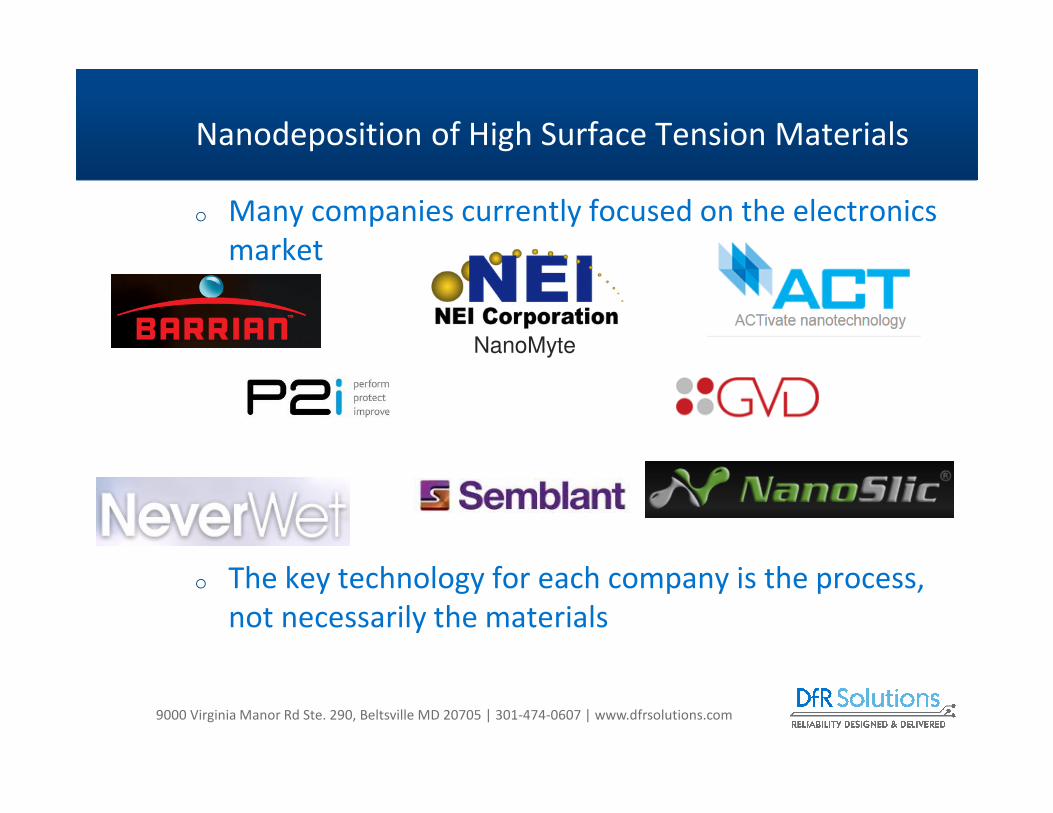
o Many companies currently focused on the electronics
market
o The key technology for each company is the process,
not necessarily the materials
Nanodeposition of High Surface Tension Materials
NanoMyte
9000 Virginia Manor Rd Ste. 290, Beltsville MD 20705 | 301-474-0607 | www.dfrsolutions.com
o Hydrophobicity tends to be driven by number and
length of the fluorocarbon groups and the
concentration of these groups on the surface
o The key points to each technology are:
o Some are chemical vapor deposition (CVD) processes, with
low vacuum requirements, Room Temperature Deposition
Process
o Variety of Potential Coating Materials (with primary focus on
fluorocarbons)
o Some incorporate nano-particles into a conventional
conformal coating
Process Technology
9000 Virginia Manor Rd Ste. 290, Beltsville MD 20705 | 301-474-0607 | www.dfrsolutions.com
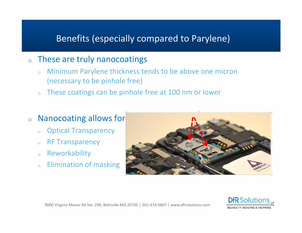
o These are truly nanocoatings
o Minimum Parylene thickness tends to be above one micron
(necessary to be pinhole free)
o These coatings can be pinhole free at 100 nm or lower
o Nanocoating allows for
o Optical Transparency
o RF Transparency
o Reworkability
o Elimination of masking
Benefits (especially compared to Parylene)

9000 Virginia Manor Rd Ste. 290, Beltsville MD 20705 | 301-474-0607 | www.dfrsolutions.com
LLCR Measurements
Current (A) 0.01
V comp (V) 0.1
Connector Male 34way Pin Header Au over nickel contact (TE Connectivity 1-215307-7)
Connector Female 34way Socket Header Au over nickel contact (TE Connectivity 1-826632-7)
Benefits: No Masking
1234567
323334
Current
Source
10mA
Nano
Voltmeter
34 way
header pins
34 way
header Socket
Rcontact = Vmeasure/10x10-3
Test Circuit
0
1
2
3
4
5
6
7
8
9
0 10 20 30 40
Re
sist
an
ce (
mO
hm
s)
Pin Number
Low Level Contact Resistance
Plasma Coated
Uncoated
Courtesy of Semblant Ltd.

9000 Virginia Manor Rd Ste. 290, Beltsville MD 20705 | 301-474-0607 | www.dfrsolutions.com53
o Voltage Breakdowno Levels tend to be lower compared to existing coatings (acrylic, urethane, silicone)
o Can be an issue in terms of MIL and IPC specifications
o Optically Transparento Inspection is challenging
o Costo Likely more expensive than common wet coatings
o However, major cell phone manufacturer claims significant ROI based on drop in warranty costs
o Throughputo Batch process. Coating times tend to be 10 to 30 minutes, depending upon desired
thickness
o However, being used in high volume manufacturing
Risks?

9000 Virginia Manor Rd Ste. 290, Beltsville MD 20705 | 301-474-0607 | www.dfrsolutions.com
o There is significant opportunity for field performance
improvement and cost reduction through the proper
use of coatings and pottings
o Requires a knowledge of the materials and processes
on the market
o Benefits vs. Risks
o With any technology, do not rely on standard
qualification tests!
o A physics-based test plan provides the most robust
mitigation
54
Conclusions


![Waterborne Epoxy Based Coating Materials · friendly coatings like powder coatings, solventless coatings, UV curable coatings and waterborne coatings [6]. The first step in this process](https://img.dokumen.tips/doc/110x75/600912c2a8aea319421a2c7d/waterborne-epoxy-based-coating-materials-friendly-coatings-like-powder-coatings.jpg)


