Embed Size (px)
Citation preview

Thermal barrier coatings technology: criticalreview, progress update, remainingchallenges and prospects
R. Darolia*
A comprehensive and integrated review of thermal barrier coatings (TBCs) applied to turbine
components is provided. Materials systems, processes, applications, durability issues, technical
approaches and progress for improved TBC, and our understanding of the science and
technology are discussed. Thermal barrier coating prime reliance and further advances have
been hampered by TBC loss by particle impact and erosion in certain locations of the turbine
blades. Accumulation of low melting eutectic containing calcia, magnesia, alumina and silica
resulting in TBC spallation limits maximum surface temperature. Design methodologies to
address durability and data scatter issues are discussed. Compositions, morphology,
characteristics and performance data for new bonds to achieve longer TBC life are described.
Further reduction in the thermal conductivity of the top layer to minimise the parasitic mass of the
coating on the component is being sought via top layer composition and processing
modifications as well as by alternate ceramic compositions. The progress in these areas is
critically reviewed including processing, stability and durability limitations. The paper also
describes effort to understand various failure mechanisms including modelling and simulation.
Keywords: Thermal barrier coatings, Bond coat, Yttria stabilised zirconia, Low thermal conductivity, EB-PVD, CMAS, Erosion, Impact, Designmethodology
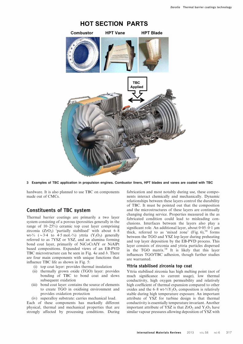
IntroductionApplication of thermal barrier coatings (TBCs) oncooled turbine engine components such as combustors,high pressure turbine (HPT) blades and HPT nozzles isincreasing in commercial and military jet engines. Thistrend will certainly continue because the insulatingcapability of TBC enables higher operating temperaturesand/or permits a reduction in the required amount ofcooling air, thereby improving efficiency, reducingemission and increasing thrust/weight ratio. Powergeneration turbine engines are also increasingly usingTBC. Thermal barrier coatings are also slated to be usedon components made out of ceramic–matrix composites(CMCs).
A schematic of a TBC system on an HPT blade isshown in Fig. 1. Thermal barrier coatings are currentlyused to provide metal temperature reductions of up toy100uC (Fig. 1b), while potential benefits are estimatedto be greater than y200uC. Factors that determinetemperature reductions include part geometry andlocation, heat flux, heat transfer coefficients, backsidecooling air, TBC thickness and thermal conductivity.The temperature benefits are highly significant and
surpass other material technologies advances includingsingle crystal Ni based superalloys (Fig. 2) achievedover a 30 year period. The initial applications weredriven by the need to suppress component degradationdue to excessive surface temperatures in combustors andsome selected turbine aerofoils experiencing oxidationdamage. In spite of significant improvements, TBCs areyet considered ‘prime reliant’ because of local spalls andreduction in thickness, and full utilisation has eludedturbine designers. Research and technology develop-ments have been carried out for the last two decades toaddress performance and reliability while extensiveresearch is being carried out for higher temperatureapplications beyond the baseline system, and for TBCwith lower thermal conductivity.
Thermal barrier coatings are complex, multilayeredand multimaterial systems with many variants related tocomposition, processing and microstructure. There areover 400 publications on this subject. This review paperwill describe the currently used TBC materials systemsand summarise our current understanding of the science,technology and failure mechanisms. Emphasis will beplaced on engineering application aspects to draw onthe author’s vast experience directing TBC research ata major aerospace company in collaboration with manyuniversities and national laboratories. References select-ed based on relevance and scientific value are provided.Recent review papers1–10 capture various aspects of the*Corresponding author, email [email protected]
(Retired) GE Aviation, 7377 Overland Park Court, West Chester, OH45069, USA
� 2013 Institute of Materials, Minerals and Mining and ASM InternationalPublished by Maney for the Institute and ASM InternationalDOI 10.1179/1743280413Y.0000000019 International Materials Reviews 2013 VOL 58 NO 6 315

TBC technology and provide excellent additional back-ground. The author has also relied heavily for insight forhis research on papers in five conference proceedings‘Science and technology of zirconia, Volumes I–V’11–13
that are excellent sources for fundamental informationon sintered or hot pressed ‘bulk’ zirconia based ma-terials. The author has found that the properties andbehaviour in the coating form are quite similar to thoseof the bulk materials.
Thermal barrier coating applicationThermal barrier coatings are applied to componentswhich are internally cooled by directing air thoughchannels. Designs with TBC coated parts consider partconfiguration and thickness, heat flux, heat transfercoefficients, combustion and turbine inlet temperaturesand total cooling air allowed by the system engineers. Tominimise adding excessive mass and cooling holeclosure, thinner coatings are preferred.
Main components in propulsion turbine engines whereTBC is applied are shown in Fig. 3. The combustor linerswere the first components to routinely use TBC appliedby an air plasma spray (APS) process. Thermal barriercoatings on aeroturbine blades are applied by an electronbeam physical vapour deposition (EB-PVD) process. Thelarger components of the power generation turbines(combustor, several stages of nozzles and blades, referr-ed to as buckets) predominantly use the APS processbecause of their larger size. Thermal barrier coatingthickness on aerorotating parts is typically 100–250 mmcompared to 250–500 mm on the stationary componentssuch as shrouds, nozzles and combustor parts. In theseparts, both EB-PVD and APS processes are consider-ed. The rationale for the process choices will be describ-ed in the section on ‘Processing methods for top coat’.Component designs with TBC have evolved from simplyapplying a thin layer of TBC on existing components tosophisticated design practices based on laboratorytest data and observations from the field returned
2 Turbine temperature advancement with TBC compared
with Ni based superalloys
1 a An HPT blade coated with TBC. TBC components (bond coat and top coat) are shown with temperature drop though
the thickness of TBC. b An example of temperature drop in an HPT by TBC application
Darolia Thermal barrier coatings technology
316 International Materials Reviews 2013 VOL 58 NO 6
hardware. It is also planned to use TBC on componentsmade out of CMCs.
Constituents of TBC systemThermal barrier coatings are primarily a two layersystem consisting of a porous (porosities generally in therange of 10–25%) ceramic top coat layer comprisingzirconia (ZrO2) ‘partially stabilised’ with about 6–8wt-% (y3?4 to 4?5 mol.-%) yttria (Y2O3) generallyreferred to as 7YSZ or YSZ, and an alumina formingbond coat layer, primarily of NiCoCrAlY or NiAlPtbased compositions. Expanded views of an EB-PVDTBC microstructure can be seen in Fig. 4a and b. Thereare four main components with unique functions thatinfluence TBC life as shown in Fig. 5:
(i) top coat layer: provides thermal insulation(ii) thermally grown oxide (TGO) layer: provides
bonding of TBC to bond coat and slowssubsequent oxidation
(iii) bond coat layer: contains the source of elementsto create TGO in oxidising environment andprovides oxidation protection
(iv) superalloy substrate: carries mechanical load.Each of these components has markedly differentphysical, thermal and mechanical properties that arestrongly affected by processing conditions. During
fabrication and most notably during use, these compo-nents interact chemically and mechanically. Dynamicrelationships between these layers control the durabilityof TBC. It must be pointed out that the compositionand the microstructures of these layers are continuallychanging during service. Properties measured in the asfabricated condition could lead to misleading con-clusions. Interfaces between the layers also play asignificant role. An additional layer, about 0?05–0?1 mmthick, referred to as ‘mixed zone’ (Fig. 6),14 formsbetween the TGO and YSZ lop layer during preheatingand top layer deposition by the EB-PVD process. Thislayer consists of zirconia and yttria particles dispersedin the TGO matrix.14 It is likely that this layerinfluences TGO/TBC adhesion, though further studiesare warranted.
Yttria stabilised zirconia top coatYttria stabilised zirconia has high melting point (not ofmuch significance to current usage), low thermalconductivity, high oxygen permeability and relativelyhigh coefficient of thermal expansion compared to otheroxides and the 6–8 wt-%Y2O3 composition is relativelystable during high temperature exposure. An importantattribute of YSZ for turbine design is that thermalconductivity is essentially temperature invariant. Anotherimportant attribute of YSZ is that ZrO2 and Y2O3 havesimilar vapour pressures allowing deposition of YSZ with
3 Examples of TBC application in propulsion engines. Combustor liners, HPT blades and vanes are coated with TBC
Darolia Thermal barrier coatings technology
International Materials Reviews 2013 VOL 58 NO 6 317

uniform composition by the EB-PVD process. This isunlike alternate TBC materials containing oxides ofdifferent vapour pressures yielding undesirable, non-uniform and layered structures. Yttria stabilised zirco-nia is applied either by APS or EB-PVD techniques.These processes make YSZ ‘strain tolerant’ by deposit-ing a structure that contains numerous pores, gaps,microcracks and interfaces (Fig. 7). Strain tolerantstructures are necessary to accommodate thermalexpansion misfit between the substrate and top layer.The high oxygen permeability of the YSZ requires thatthe bond coats be highly resistant to oxidation and hotcorrosion attack. The bond coat compositions are richin aluminium to form a protective, TGO scale of a-Al2O3, typically 1–6 mm. The NiCoCrAl (Y, Hf, Si andRe) type overlay bond coats, typically 100–200 mm, aremainly based on the c-Ni and b-NiAl phases. The Ptplatinum modified diffusion aluminide bond coats,typically 50 mm, mainly consist of a b-NiAl–Pt phase.
In addition to enhancing oxidation resistance, TGOserves to bond the ceramic top coat to the substrate/bond coat system. Thickening and buckling of the TGOscale and subsequent cracking is one of the severalfailure mechanisms of TBC. The adhesion and mechan-ical integrity of the TGO scale is dependent on thecomposition and impurity levels of the bond coat.
A pseudobinary ZrO2–Y2O3 phase diagram modifiedby Levi1 is shown in Fig. 8. In this figure, the Y2O3
content in the x axis is labelled as mole fraction YO1?5
since wt-%Y2O3 roughly translates to 0?5 mol.-%Y2O3
in ZrO2–Y2O3 compositions. Numerous modifica-tions to precisely define phase boundaries have beenproposed.15 As opposed to the equilibrium tetrago-nal phase t (t-ZrO2), a closely related non-equilibrium,metastable phase t (t’-ZrO2) is obtained in the asdeposited TBC due to high rate deposition by eitherAPS or EB-PVD. This phenomenon is highly desirablefor achieving optimised lives. Though thermodynami-cally driven to partition into equilibrium tzc, the t’phase does not transform easily to tetragonal andmonoclinic phases under normal circumstances until atleast y1200uC,16,17 which is adequate in current use.Stability will become an issue for higher temperatureoperations. Transformation to monoclinic phase atlower Y2O3 contents is undesirable due to significantvolume change (y3 to 4%) causing cracks and TBCspallation. Higher Y2O3 contents have been shown tohave lower fracture toughness, a possible cause oflower erosion and impact resistance to be discussedlater.
During the initial TBC development originating atNASA during the 1970s, it was demonstrated byStecura18–20 in APS TBC that about 6–8 wt-% (y3 to4?5 mol.-%) Y2O3 addition to ZrO2 provided the longestTBC thermal cycle life in burner rig tests, even thoughZrO2 was not fully stabilised. This conclusion wasdrawn with different test temperatures and various bondcoat compositions. Time to first crack related tosubsequent TBC spallation in thermal cycle tests as afunction of Y2O3 content and four composition varia-tions of NiCrAlY bond coat is shown in Fig. 9. Later,Stecura evaluated Yb2O3 containing ZrO2 and con-cluded that maximum life is obtained between 12?4 and14?7 wt-%Yb2O3. Thermal barrier coating life decreasedvery rapidly at concentrations exceeding these optimumvalues. It must be pointed out that, after extensiveresearch for the last two decades to identify better topcoat compositions, 6–8 wt-%Y2O3 content in ZrO2continues to be optimum. Alternate oxide stabilisersevaluated primarily to reduce thermal conductivity haveshown TBC lives to be inferior to YSZ to be discussed ina later section. To date, YSZ continues to be a materialsystem of choice. It is interesting to note that Engelet al.21 observed on ‘single-crystal’ ZrO2 that maximumfracture toughness and fracture strength are obtainedaround 4–5 wt-%Y2O3 (Fig. 10).
It has been proposed by Virkar22,23 and Baither et al.24
based on experiments on sintered ZrO2–3 mol.-%Y2O3
specimens that the t’ phase microstructure consists oflarge grains on the order of 100 mm or greater. Thesegrains contain very small domains (y0?1 mm) arrangedin three mutually orthogonal orientations in each grainmaking t’ phase extremely non-transformable. How-ever, these domains reorient under stress that provides
4 a TBC microstructure with four components (Ni based
superalloy, bond coat, TGO and YSZ top coat). Note
the columnar microstructure of the zirconia coating.
The white band is an interdiffusion layer between the
Al rich bond coat above and the Ni rich superalloy. b
Expanded view of zirconia top coat
Darolia Thermal barrier coatings technology
318 International Materials Reviews 2013 VOL 58 NO 6

high toughness, a phenomenon called ferroelastic domainswitching. Mercer et al.25 and co-workers have arguedbased on indentation and TEM studies that the nuclea-tion of domains contributes to the toughness of YSZTBC, and not the switching. This assertion was drawn byexamining the material in the wake of an indentationinduced crack by using TEM and by interferometry.
Yttria stabilised zirconia compositions are thermallystable up to the current use temperatures of TBC which is
y1200uC. Yttria stabilised zirconia has shown minimumpartition to the cubicztetragonal phases which in turn
transform to tetragonalzmonoclinic phases respective-ly, upon cooling. It is another desirable attribute since
destabilisation and subsequent monoclinic formation canlead to TBC spallation. Investigation on the thermal
stability of YSZ and ZrO2 containing various stabilisershas been conducted more recently by Rebollo et al.16
At higher temperatures, in addition to destabilisation,
sintering can modify pore structure influencing thermalconductivity as well as strain tolerance.
Processing methods for top coat
Thermal barrier coatings are porous with overallporosities generally in the range of 10–25%. In the EB-PVD process, an ingot (or ingots) of a YSZ compositionis vapourised in a vacuum chamber using a focusedelectron beam. Before deposition, the samples are pre-heated to y1000uC in a low oxygen partial pressureenvironment resulting in the growth of a thin (y0?05 to0?1 mm) TGO layer. The parts are coated by manipula-tion within the vapour cloud on the preheated substratesurface. The EB-PVD process is especially effective intailoring microstructures and inplane modulus. Forexample, EB-PVD can yield a very desirable columnarmicrostructure (Figs. 7 and 11) to result in a low inplanemodulus that provides strain accommodation for thecoefficient of thermal expansion mismatch between themetallic substrate and the ceramic top coat. The airplasma spray process yields a microstructure withhorizontal splats of YSZ (Fig. 11). The interfaces/gapsbetween the splats provide additional reduction in
6 a TGO microstructure, predominantly a-Al2O3 and b mixed zone of a-Al2O3zZrO2
5 Thermal barrier coating consists of four main components with unique functions that influence TBC life
Darolia Thermal barrier coatings technology
International Materials Reviews 2013 VOL 58 NO 6 319

thermal conductivity and thermal expansion compliancewith the substrate. The pore structure characteristics ofEB-PVD and APS are schematically shown in Fig. 12(reproduced from Ref. 26). Various versions of theplasma spray processes are used as an alternative tothe expensive EB-PVD process. Excellent reviews of theAPS process and processing parameters, and the controlof coating characteristics and properties are provided bySampath.26,27 During preheating and top coat deposi-tion, and during subsequent heat treatments, the bondcoat generates an adherent a-alumina layer (TGO) be-tween the bond coat and the YSZ top coat. Forma-tion of this a-alumina of optimal thickness andcrystallography is critical to achieve reproducible TBClife and prevent premature spallation of the TBC. ATGO thickness of about 0?3–1?0 mm is consideredoptimum right after deposition.28 The TGO thickensduring the TBC use, eventually contributing to TBCspallation. Thermal barrier coating failure mechanismsare discussed in the section on ‘Temperature and ther-mal cycle dependent failure’.
Process selection considers performance, capital cost,per-part process cost, thickness requirements and con-trol, composition requirements and control, surface
roughness requirement, line of sight versus non-line ofsight characteristics and degree of cooling hole closure.The EB-PVD process provides longer TBC life,smoother coating with excellent composition and thick-ness control, and causes minimum cooling hole closure.This process is preferred for blades and vanes in spite ofmuch higher cost compared to the APS processes.
Air plasma spray processes are used for combustorparts, HPT shrouds and on most power generationcomponents due to lower cost and requirement forthicker coatings. A variation of the APS process that isincreasingly being used is ‘dense vertically cracked’(DVC) TBC coating process.29 Vertical cracks areintroduced to provide strain tolerance and serve similarfunction as intercolumnar gaps in the EB-PVD coatingsat much lower cost. However, the performance iscompromised in this lower cost version of the EB-PVDprocess.
Promising newer processing methods that are attemp-ting to compete with EB-PVD and APS include directedvapour deposition, a variation of the EB-PVD processwhere a supersonic gas jet is used to direct vapours ontocomponents being coated to increase process efficiencyand deposition rate. The process acts as a non-line ofsight process, and is able to coat multiple componentswith complex geometry.30–32 Composition uniformityand microstructural flexibility are other beneficialattributes. Suspension plasma spray or liquid solutionprecursor plasma spray33–35 creates microstructures withhigh segmented crack density and finer pores forreduced thermal conductivity and improved thermalcycle performance. The process employs suspensions ofsubmicrometre particles as feedstock. This circumventsflow issues with finer particles in a powder feedstock,thereby, improving process efficiency. Microstructure
a column gaps; b feathers on columns; c porosity incolumns due to rotation
7 Types of TBC porosity
8 The zirconia rich corner of the ZrO2–YO1?5 binary phase
diagram. Yttria stabilised zirconia composition and
operating temperature range are shown by the hatched
region. The tetragonal prime phase is metastable within
the To bounds shown as dashed lines superimposed
on the phase diagram (courtesy: Professor Carlos Levi,
UCSB)
Darolia Thermal barrier coatings technology
320 International Materials Reviews 2013 VOL 58 NO 6

and composition flexibility are two other advantages. Arecent review of the developments in this technology isprovided by Killinger et al.36
Bond coatBefore introduction of TBC, turbine blades and vaneswere protected from oxidative and corrosive environ-ments with either diffusion coatings such as single phase,simple, b-NiAl or Pt modified b-NiAl or two phaseoverlay czb MCrAlX coatings (where M represents Nior Co and X represents Y, Hf, Si, or other minoradditives such as Re). The choice between these coatingtypes by turbine engine manufacturers was based on
experience, design philosophy, performance and cost.Although designed originally for environmental resis-tance, these coatings have been used as bond coats forTBC applications without any specific compositionmodifications and process development.
The MCrAlX type bond coats usually contain (inwt-%) 15–25%Cr, 10–15%Al and 0?2–0?5%Y, and con-sist of a b-NiAl phase in a c-Ni matrix. These coatings,typically 100–150 mm thick, are applied using a varietyof overlay processes: APS, high velocity oxyfuel, lowpressure plasma spray, cathodic arc/ion plasma deposi-tion or EB-PVD. The overlay coating processes areabout 2–4 times more expensive than the diffusion
9 Time to first crack and subsequent TBC spallation in a thermal cycle test as a function of Y2O3 content for APS TBC
(Stecura18–20)
10 Flexure strength and fracture toughness of ZrO2 single crystals as a function of Y2O3 content (Engel et al.21)
Darolia Thermal barrier coatings technology
International Materials Reviews 2013 VOL 58 NO 6 321

processes, but offer much greater control of the coatingcomposition since the coating composition is dictatedessentially by the composition of the coating source.This attribute provides flexibility in depositing bondcoat layers of various different chemical compositions.In actual practice, a knowledge of the vapour pressure,deposition efficiency and spatial distribution of all thechemical elements of the coating is required. The b-NiAlbond coats contain (in wt-%) 20–30%Al, and aregenerally applied by a diffusion process. Electroplatingof Pt on the surface of the alloy precedes the diffusioncycle in the Pt modified b-NiAl bond coats. Thediffusion processes enrich the component surface withAl. The composition of a diffusion coating is dictated bythermodynamic and kinetic constraints, and there arelimitations on what multicomponent compositions canbe deposited in reproducible and cost effective manner.The thickness is typically limited to about 40–60 mm.The b-NiAl coatings consist of an interdiffusion zonetypically about the thickness of the top layer sandwiched
between the alloy and the b-NiAl layer. A typicalmicrostructure of TBC with a b-NiAl type bond coatand a TGO layer between the bond coat and the YSZtop layer is shown in Fig. 4a.
It must be strongly emphasised that environmentalcoatings form and reform the TGO layer as the coatingis thermally cycled. In TBC applications, TGO spalla-tion leads to TBC spallation. A significant level ofunderstanding has been developed over the last twodecades on various stages of TGO formation, growthand adhesion. The effects of major elements (aluminium,chromium and platinum) and minor elements additions(Y, Hf, Zr, Si, Pt and Re) have been studied extensivelyin bulk alloys and coatings. Of these, additions of smallamounts of Hf, Y, Zr, Si and the elements (e.g. Ti, S, Hfand W) diffusing into the coating from the substrateplay a critical role.6,37–59 A thin layer of Pt over a gritblasted NiCoCrAlHfSi coating surface has demon-strated a beneficial effect,44 though, this observationwould have limited industrial application due to high
a EB-PVD; b APS; c DVC11 Thermal barrier coating top coat microstructures
12 An illustrative description of microstructures of TBCs across length scales. The defect architectures of plasma
sprayed coatings are differentiated from those of EB-PVD coatings26
Darolia Thermal barrier coatings technology
322 International Materials Reviews 2013 VOL 58 NO 6

cost of Pt. The effect of grit blasting,57 preoxidation58
and post-oxidation60 has been studied. Some of thesemodifications alter transformation kinetics of transientalumina such as h-Al2O3 to a-Al2O3, faster establish-ment of a-Al2O3 being desirable.59 A remarkable effecton initial stages of oxide formation, transformation andgrowth kinetics has been demonstrated by Gleeson whenY, Hf and Si are added synergistically (codoping) at verylow levels (Fig. 13).61 An excellent summary of researchon the oxidation mechanism and bond coat composi-tions is provided by Gleeson.5 Impurities such as S andC in the starting materials and introduced duringprocessing have a critical role on TGO scale adhesion,sometimes leading to infant mortality. The impurityeffect will be discussed in section TBC scatter. A recentreview on alumina scale formation is given by Heueret al.10
Thermal barrier coating operating at higher tempera-tures will require improved bond coats capable ofoperating at higher temperatures. This is especially trueif TBCs are used as a prime reliant coating. LocalisedTBC loss due to foreign object impact will probably bedifficult to avoid. In this case, TBC loss will expose andrapidly oxidise the bond coat, causing rapid degradationof underlying substrate. However, it must be recognisedthat bond coat materials and the underlying substratehave similar thermal conductivities, and, therefore,improvement in bond coat temperature capability willbe limited by the creep strength of the substrate. Itshould be pointed out that the extent of coating/substrate interdiffusion will increase as the operatingtemperature of the turbine increases. An ideal bond coatshould have the following attributes:
(i) oxidation resistance by forming a slow growing,non-porous, continuous and adherent a-Al2O3
scale layer (TGO)
(ii) minimal interdiffusion with the substrate tominimise Al depletion and upward diffusion ofrefractory elements and impurities such as S,and avoid formation of ‘secondary reactionzone’ (SRZ) below the bond coat on the newergeneration of Ni based superalloys
(iii) minimal strain misfit with the substrate result-ing from thermal expansion differences
(iv) high creep strength to suppress plasticity/rum-pling effect (to be discussed in the section on‘Thermal barrier coating damage and degrada-tion mechanisms’)
(v) compatibility with the processes to coat internalcooling passages of the blade
(vi) minimum use of Pt and other expensiveelements such as Ru, Re and Pd
(vii) minimally affected by impurities such as S, C,etc.
The newer generation Ni based superalloys contain highlevels of rhenium (Re) and relatively higher levels of Al.The higher levels of alloying elements tend to causemicrostructural instability. Specifically, Re has beenidentified as a key alloying element promoting an SRZlayer beneath the coating layer (Fig. 14). The SRZ layerconsists of a c’ matrix containing c and P phase (TCP)needles (as opposed to a c matrix containing c’ of atypical Ni based superalloy). The SRZ formation hasbeen demonstrated to be detrimental to the creep andrupture properties of the alloys.62 To address the SRZ
issue, Rickerby et al.63,64 and Gleeson et al.65 havedeveloped lower aluminium containing bond coatschemically compatible with the Ni based superalloysubstrate. Rickerby applies a thin layer of Pt followed bya diffusion heat treat to create a Pt modified czc9
coating layer. With investigation of phase equilibria at1100 and 1150uC in the Ni–Al–Pt system, Hayashiet al.66 have identified czc9 bond coat compositions thathave demonstrated oxidation performance matching theconventional MCrAlX and a b-NiAl coating. To addressthe high cost of Pt, Gleeson61 has developed coatingcompositions with lower Pt levels in combination withlow level additions of Hf, Y and Si.
A modified version of a b-NiAl bond coat has beendeveloped by Darolia et al.67–71 at GE Aviation usingoverlay processes such as ion plasma deposition, APSand EB-PVD. The bond coat is predominantly a bphase, and contains (in wt-%) about 20–25Al, 5Cr, 0?25–0?5Zr and/or 0?25–0?5Hf. The bond coat was designedbased on the author’s extensive knowledge gainedduring the development of NiAl based intermetallicalloys for turbine applications.72–74 A large library ofNiAl compositions is available in single crystal formto evaluate oxidation resistance and TBC coated life.Compositions were selected based on the knowledgeof strengthening behaviour in single crystal NiAl todevelop an oxidation resistant and ‘strong’, creep re-sistant bond coat. Thermal expansion data were usedto match thermal expansion of the coating with theunderlying substrate. Reactive element doped NiAlcoupons coated with TBC and tested to spallationfailure showed that minor additions of Hf or Zr to NiAlprovided substantial increases in the TBC spallation lifeas seen in Fig. 15. The improvement was linked, in part,to increase in the room and high temperature strengthsprovided by solid solution strengthening by Cr insolution within the b phase matrix of the coating anddispersions of a-Cr particles, and by the b9-Heuslerphase Ni2Al(Hf, Zr) precipitates within the b phasematrix of the coating (Figs. 16–18). In addition, TGOscale adherence was provided, in part, by Zr or Hf oxidepegging.
A programme was initiated to translate the improvedperformance of the TBC coated NiAl single crystal
13 Synergistic beneficial effect of Hf, Si and Y in a b-
NiAl coating composition61
Darolia Thermal barrier coatings technology
International Materials Reviews 2013 VOL 58 NO 6 323

alloys into bond coat compositions. The result wasdevelopment of an overlay b phase NiAlCrZr bond coatstrengthened to prevent rumpling. As an example,dependence of TBC life in a NiAlCrZr bond coatingas a function of Zr content is shown in Fig. 19. Thermalexpansion match with the substrate is demonstrated asshown in Fig. 20. In addition to increased oxidationresistance and TBC life in laboratory and engine tests,the bond coat has demonstrated reduced wall consump-tion of the turbine blade. Reduced rumpling resulted inunderlying substrate running cooler by maintaining asmooth air flow boundary layer on the surface (Fig. 21).The NiAlCrZr bond coat has been introduced in GEAviation’s new engines such as GEnx for the Boeing 787Dreamliner airplane.
Diffusion barriersOwing to increased interdiffusion expected in highertemperature applications, and to avoid SRZ formation,extensive development effort has been made to identifydiffusion barrier layers applied between the bond coatand the substrate to block interdiffusion. Multilayerbond coats incorporating a combination of diffusion andoverlay processes have been evaluated. Diffusion barriermaterials have included metallic (i.e. Re and Ru), in-termetallic (i.e. sigma and laves phases) and oxides.75–78
Majority of the work has been on Ru containing layers.Ru and Re are demonstrated to be effective barriers, butpossess poor oxidation resistance. Alloying to adequatelyimpart oxidation resistance to Ru and Re has not beendemonstrated. Oxide barriers have durability issuesduring thermal cycling. So far, a diffusion barrier layerthat meets all of the critical requirements, namely, goodadhesion (due to thermal expansion difference), oxidationresistance (or does not oxidise such as an oxide layer),TBC durability during thermal cycling and practical andcost effective processing is yet to be developed, andcontinues to challenge materials scientists.
Thermal conductivity lower than YSZ(low k TBC)There is a significant design benefit in lowering thethermal conductivity and density of the top coat toreduce parasitic mass of the coating especially on the
rotating parts such as turbine blades. For higher gaspath temperatures, thicker coatings required to maintainconstant metal temperatures are undesirable. Hence,considerable effort has been directed for the last twodecades towards reducing thermal conductivity by one-third to one-half. Thermal conductivity k (W m21 K21)is often calculated from measurements according to theformula k5arCp, where k is the thermal conductivity, ais the thermal diffusivity measured by a flash diffusivitymeasurement technique, r is the density of the coatingsand Cp is the specific heat.
In addition to the composition of the startingmaterial, thermal conductivity is highly influenced bythe density and microstructure (e.g. defect structure,porosity, grain boundaries/interfaces, splat boundariesin APS TBC and second phases) of the coating. It is alsoimportant that the deposited microstructure, with theoptimal porosity level, defect structure and interfaces, bestable during high temperature exposures during theengine operation. Some of the highest thermal con-ductivity reductions have been achieved with highlyporous microstructures. Thermodynamically unstablestructures experience a loss or redistribution in vacancyconcentration, and coarsening of micropores as well assintering during exposure. Such changes cause increasein thermal conductivity by reducing the number ofmicrostructural sites available to scatter the thermalwave (phonons). Approaches to lower the thermalconductivity have included the following: YSZ composi-tion modifications including partial or total substitutionof Y2O3 by codoping with rare earth oxides to increasecrystalline lattice disorder and oxygen vacancies byvarying the type and amount (i.e. ionic radius or mass)of stabilisers; process modifications for microstructurechanges including porosity increase; and alternateceramic systems: the efforts have been mainly focusedwith plasma spray processing since most alternateceramic compositions are difficult to deposit uniformlyby EB-PVD. Excellent reviews of the scientific basis forapproaches for reduced conductivity are provided byKlemens and Gell,79 Clarke80 and Mevrel et al.81 Beforewe discuss the progress made with these approaches, the
14 An SRZ is created between the coating and a high Re
containing Ni based superalloy15 Thermal barrier coating spallation life for TBC coated
single crystal NiAl compositions containing small
amounts of Zr, Hf and Ti (compositions in at-%) com-
pared with stoichiometric NiAl (50/50)
Darolia Thermal barrier coatings technology
324 International Materials Reviews 2013 VOL 58 NO 6

author would like to point out the lessons learneddirecting this effort over 20 years.
(i) Different top coat ceramic compositions resultin different as deposited microstructures anddensity, and it is difficult to separate composi-tion and microstructure effects. Therefore,claims for lower thermal conductivity with agiven composition should be analysed carefully.The theoretical/intrinsic thermal conductivity ofYSZ is approximately 2?2 W m21 K21 and islinked to its composition and phase structure. Itis the processing induced microstructure, por-osity being a major contributor, that causes a25–50% reduction in conductivity from thetheoretical value. In case of EB-PVD, proces-sing parameters such as surface preparation,substrate temperature, processing temperatureand chamber pressure including oxygen partialpressure, and deposition rate, angles and rota-tion significantly affect microstructure (e.g.volume fraction, geometry and distribution ofthe pores, column gaps and interfaces).82–86 Itshould be mentioned that the conductivity of
APS TBC can be as low as 0?8 W m21 K21, thesplat boundaries being major contributor forreduction.
(ii) The alternative oxide stabilisers to ZrO2 have,in most cases, vast vapour pressure differencesas shown in Fig. 22 (reproduced from Schulzet al.87). The vapour pressure difference yieldsundesirable layered and non-uniform micro-structures, at least in the case of EB-PVDprocessing. Dual source processing and otherprocessing advancements can overcome thisissue, in turn, adding to complexity and cost.
(iii) It has been demonstrated that the ‘low k TBC’compositions, unlike YSZ, do not ‘bond’ toTGO. Lower interface toughness is consideredto be the cause, though, further studies arewarranted. This lack of bonding requires a YSZ‘bonding’ underlayer below the new ceramic topcoat. This requirement adds to processing stepsand associated process reliability, and cost. Thisis certainly an undesirable requirement.
17 Improvement in rupture strength (life) at 982uC/
124 MPa in the ,110. orientation with alloying addi-
tions such as Hf, Ti and Ta to a NiAl (50Ni–49?3Al–
0?5Hf–0?2Ga) single crystal composition. The composi-
tions are shown in at-%
18 Microstructure of a NiAlCrZr bond coat composition
showing Cr particle dispersions and b’ precipitates
that contribute to strengthening of the bond coat
19 Thermal barrier coating spallation life results from fur-
nace thermal cycle testing of NiAlCrZr coatings pro-
duced by EB-PVD method as a function of Zr
content68
16 Effects of small amount of alloying additions on the
,100. room temperature fracture strength of single
crystal NiAl compositions
Darolia Thermal barrier coatings technology
International Materials Reviews 2013 VOL 58 NO 6 325

(iv) The particle erosion and impact resistanceof baseline YSZ, discussed in the section on‘Erosion and impact damage’, need improve-ment based on field observations. Unfor-tunately, the ‘low k TBC’ compositions havedemonstrated, in most cases, inferior resistanceassumed due to their reduced fracture tough-ness. Understanding the relationship betweenimpact resistance, composition and processingwill be key to developing a well balanced, nextgeneration ‘low k TBC’.
(v) There is significant scatter and error in the laserflash diffusivity measurements primarily due toerrors in thickness and density measurements.Therefore, reported thermal conductivity valuesare sometimes suspect.
(vi) Microstructural and phase stability will becomeimportant issues when TBCs are used at higher
engine operating temperatures. Phase stabilityof new TBC compositions has been studied byRebollo et al.,16 Cairney et al.88 and Kakudaet al.89 During use at the operating tempera-tures of y1200uC, the feather-like features ofEB-PVD coatings progressively disappear andtransform into a microstructure of dispersedpores. Additionally, the columns join togetherto form blocks separated by cracks perpendi-cular to the interface. These so called ‘aging’effects have been shown to increase thermalconductivity.90,91 Loss of strain complianceleading to TBC spallation is also a critical issue.
(vii) Radiative heat transfer from the gas, currently aminor contributor to the blades, could signifi-cantly increase in higher temperature turbines.Development of erosion and impact resistantreflective layers will become an area of futuredevelopment.
Yttria stabilised zirconia compositionmodifications including codoping with otherstabilisersIncorporation of Y2O3 to the ZrO2 fluorite crystalstructure creates a defect structure (solute Y atoms andoxygen vacancies). In baseline YSZ, one oxygen vacancyis created for every two yttrium cations. The amountand stability of this defect structure and the porositycreated during deposition control the as deposited andexposed thermal conductivity acting as phonon scatter-ing centres. In baseline YSZ, the easiest approach wouldbe to vary the Y2O3 content.
Substitution and addition of ternary and high orderdopants of metal (M) oxides of the form MO, MO2 orM2O3 with varying ionic radius or atomic mass havebeen evaluated while maintaining the t’ phase. There areover 50 issued patents related to low conductivity withsubtle differences in compositions and processing.Developments with the most relevance, uniqueness andimpact are discussed next.
20 Coefficient of Thermal Expansion match between a
second generation single crystal Ni based superalloy
(Rene9 N5) and NiAlCrZr bond coat (courtesy
Professor Kevin Hemker, JHU, unpublished work)
21 Engine test results with NiAlCrZr bond coat compared with NiAlPt bond coat. a NiAlPt bond coat and b NiAlCrZr
bond coat. Bond coat rumpling seen in the NiAlPt bond coat c is absent in the NiAlCrZr bond coat d. Lower oxida-
tion in the NiAlCrZr bond coat and retention of czc’ structure in the underlying superalloy was also observed
Darolia Thermal barrier coatings technology
326 International Materials Reviews 2013 VOL 58 NO 6

Numerous codoped YSZ compositions have shownlower thermal conductivity. One of first research tolower thermal conductivity conducted with ceria stabi-lised zirconia (CeSZ) as an alternate to YSZ or added toYSZ demonstrated lower thermal conductivity.92 Pro-cessing due to vapour pressure differences and inferiorerosion resistance has been major issue on the ceriacontaining TBC. In spite of this limitation, developmentin this area is continuing.87 Rickerby and Tamarin,93
Nicholls et al.,94,95 Rigney and Darolia96 and Schulzet al.97 have investigated dopants such as NiO, MgO,CaO, Nd2O3, Gd2O3, Er2O3,Yb2O3, Dy2O3, CeO2, SrO,Sc2O3, Eu2O3, Fe2O3, In2O, Sm2O3, Ho2O3, HfO2 andTa2O5 with various combinations and levels. Majority ofthese dopants have shown to reduce thermal conductiv-ity from about 25 up to 40%. A clear trend, however, ofthe effects of ionic radius and/or mass of the dopants isdifficult to establish due to scatter in data, mainly due toprocessing difficulties, microstructural differences inthe as deposited coatings and errors associated withconductivity measurement techniques.
An interesting ‘multicomponent defect cluster’ con-cept investigated by Zhu and Miller98–101 has also shownto lower thermal conductivity. Thermal barrier coatingswith oxides clusters of ZrO2–Y2O3–Nd2O3–Yb2O3
(Gd2O3, Sm2O3 and Sc2O3) have been investigated onboth plasma sprayed and EB-PVD coatings. In onestudy, the effect of the cluster dopant type withcompositions ranging from YSZ only, YSZ plus a singleNd2O3 or Yb2O3 dopant, YSZ plus both the Nd2O3 andYb2O3 in varying relative concentrations was investi-gated. It was observed that ZrO2–Y2O3 with paireddopant additions (Nd2O3zYb2O3) had lower thermalconductivity than those of YSZ, or YSZ with a singlecluster dopant, Nd or Yb. The coatings with equalamount of cluster dopants (Yb2O3/Nd2O351) oftenshowed the lowest conductivity at a given total dopantconcentration. Optimum dopant concentration wasestablished at y10 mol.-%. The results of their findingsare summarised in Fig. 23. The TEM observationsindicated nanoscale clustering of the smaller and largercations in different regions, with Y being uniformlydistributed. It has been postulated that the clusterscontribution to the phonon scattering is responsible for
larger reductions in conductivity than those found withY alone or codoped with only one of the cations atcomparable total dopant concentration. Higher thermalstability and TBC thermal cycle life comparable to thatobtained with YSZ TBC have been shown.
Yttria stabilised zirconia with HfO2 additionsYttria stabilised zirconia compositions containing haf-nia have also been evaluated by Peters et al.,4 Zhuand Miller,102 Gorman et al.,103 Singh et al.104 andMatsumoto et al.,105 since the crystal lattice of zirconiaand hafnia is isomor phous, and a complete solubilityexists. Yttria stabilised zirconia ingots generally containabout 1–2 wt-% hafnia. Larger additions of hafnia (e.g.40 wt-% zirconiaz40 wt-% hafniaz20 wt-% yttria) fur-ther reduce thermal conductivity but the largest effect of30% reduction at high temperature was reported forzirconia free 27 wt-% yttria stabilised hafnia.104 Thelatter showed a much denser and fine columnar mic-rostructure and was less susceptible to sintering. Similarfavourable lower shrinkage rates have been found forEB-PVD 7?5 wt-% yttria–hafnia samples that were notrotated during deposition. Peters et al.4 have demon-strated similar results with 32 wt-% yttria–hafnia with-out notable processing problems with nearly the samecomposition in both ingot and coating.
Pyrochlore type (A2B2O7) structuresUnlike the t’ YSZ based compositions, a new class oflow conductivity compositions based on the pyrochloretype zirconate structure [(Gd, Eu, Sm, Nd, La)2Zr2O7]have emerged, of which Gd2Zr2O7, La2Zr2O7 andSm2Zr2O7 have been studied the most.106–110 Con-ductivity reductions up to 50% have been reported. Inaddition to lower conductivity, Gd2Zr2O7 TBC has beenclaimed to provide calcium–magnesium–alumino-sili-cate (CMAS) attack mitigation,111 though, independentverification and understanding of this benefit is yet to beconducted. Several other beneficial attributes includephase stability up to at least 1500uC,16 and sluggishsintering kinetics.109,112 Some of these compositionsare rather difficult to deposit, especially by EB-PVD,uniformity of composition and microstructure being themajor issue.109 Owing to chemical incompatibility with
22 Vapour pressures of various oxides for potential additions to zirconia (Schulz et al.87)
Darolia Thermal barrier coatings technology
International Materials Reviews 2013 VOL 58 NO 6 327

TGO, a thin, about y25 to 50 mm, underlayer of YSZ isnecessary113 to negate reduced TBC life times observedwith a just a pyrochlore type zirconate top coat layer.Such underlayers have been reported for majority of‘low k TBC’ compositions.4,114 Thermochemical com-patibility issues between alumina and ZrO2–Gd2O3 arediscussed by Leckie et al.115 and an assessment of thethermodynamic parameters in the ZrO2–Y2O3–Al2O3
system is provided by Fabrichnaya and Aldinger.116
Significant conductivity reductions have been report-ed by Vassen et al.109 on zirconate variations such asLa1?7Dy0?3Zr2O7, La1?4Gd0?6Zr2O7, La1?4Eu0?6Zr2O7 andLa1?4Nd0?6Zr2O7 applied by APS.
To negate conductivity increase during service,Darolia et al.117,118 have evaluated combinations ofone or more dopant oxides for conductivity reductionalong with carbides such as YbC2, NdC2 and LaC2 ofthe dopant metals which are either evaporated from acarbide ingot source or formed by reaction during orafter the EB-PVD processing. In another approach,insoluble alumina by Rigney and Darolia,119 or aluminacombined with lanthanum oxide, chromium oxide and/or yttrium chromate by Ackerman et al.120 have beenevaluated. Insoluble particles or dispersions in the TBCstructure provide additional sites for phonon scatteringas well as stabilise the structure during subsequentexposure.
New ceramic compositionsOther suggested compounds121,122 with very limited con-ductivity data as a coating are: hafnates such as La2Hf2O7,monazites such as LaPO4, magnetoplumbite structuressuch as LaMgAl11O19 and LaLiAl11O18?5, garnets such as
Y3AlxFe52xO12, Y3Fe5O12, W3Nb12O44, mullite, TiO2,ZrSiO4, ZrTiO4, perovskite structures such as SrZrO3,BaZrO3 and rare earth aluminates such as RE2SrAl2O7.122
Of these compounds, CaxMg1–xZr4(PO4)6 (abbreviatedas CMZP) has been reported with a conductivity of0?7 W m21 K21 at 1000uC.123 Perovskites (ABO3) canaccommodate a wide variety of different ions in solidsolution including ions with large atomic mass. Some ofthese compounds are stable to very high temperatures,and have the potential to be developed as future lowconductivity materials. Processing as a coating withcontrolled uniform composition, however, will be aserious challenge.
An excellent summary of reported thermal conductiv-ity data is provided by Levi,1 and reproduced in Fig. 24.There appears to be a minimum value obtainable around610 wt-% of the total stabiliser additions. Thermal barriercoating life as determined in furnace thermal cycle testssuperimposed in the ZrO2–Y2O3 phase diagram by Levi isshown in Fig. 25. It is interesting to note that the TBC lifehas a maximum value around 6–10 wt-% of the totalstabiliser additions (irrespective of the type of stabiliser)to ZrO2. Non-transformable tetragonal (t’) phase is thepredominant phase in this composition range.
Processing modificationsProcessing modifications to incorporate porosity is theeasiest approach to reduce the thermal conductivity ofYSZ. However, the porosity reduction is only effective ifthe porosity is retained via improved sintering resis-tance. For EB-PVD, in addition to porosity within thecolumns, their feathery structure and gaps betweenthe columns play a significant role. For APS, splat
23 Thermal conductivity of various oxide cluster TBCs as a function of total dopant concentration after 5 or 20 h laser
high heat flux tests at 1316uC (Zhu and Miller98–101)
Darolia Thermal barrier coatings technology
328 International Materials Reviews 2013 VOL 58 NO 6

boundaries which are essentially perpendicular to theheat flow cause conductivity reductions as low as 50% offully dense YSZ in contrast to y30% for EB-PVD YSZ.The EB-PVD processing parameters that have beendemonstrated for microstructure modifications includethe following:
(i) pressure during processing
(ii) oxygen partial pressure
(iii) part temperature during preheat
(iv) part temperature during coating
(v) alternate part motions
(vi) bond coat roughness/texture.
It must be pointed out that high temperature exposureduring service will densify the coating structure via porecoarsening and sintering, negating the porosity effect.Thermal barrier coating durability for majority of newTBC compositions under thermal cycling is reduced andthe erosion rate is increased. The decreased performancehas been attributed to lower toughness rendering thesystem susceptible to delamination internally in the TBCupon thermal cycling.8 Non-compatibility with TGO isalso a major contributor.
Thermal barrier coating damage anddegradation mechanismsThermal barrier coating failures are generally classifiedinto two categories: thermal cycle dependent failure,termed ‘intrinsic failure’ and temperature independentfailures, termed ‘extrinsic’ failure which is caused byparticulates in the gas turbine environment leading totop layer thinning, densification, cracking and completeloss/spallation. At temperatures .1200uC, CMAS par-ticles can deposit onto the TBC surface, melt andpenetrate the TBC structure, changing the near surfacemechanical properties and enhancing the TBC spallationtendency. A schematic of various degradation modesproposed by Evans et al.8 is shown in Fig. 26. Thevarious degradation modes are described in the follow-ing sections.
Temperature and thermal cycle dependentfailureNot surprisingly, engine thermal cycles (e.g. tempera-ture, dwell time, rates of excursions, gradients andcycling frequency) play a significant part in TBCfailures. The oxidation of the bond coat results in theformation and growth of the TGO that induces stressesand displacements at the TGO/TBC/bond coat inter-faces eventually leading to TBC spallation. Extensiveresearch has been carried out to establish the variousmechanisms and factors that control TBC spallation inboth EB-PVD and APS TBC.124–144 In spite of over 50publications on this subject, arguments still persist. Therelative roles of plasticity of TGO and the bond coat aswell as phase transformations in the bond coat due to Aldepletion are still being debated. During engine opera-tion, several interrelated thermal cycle dependentphenomena take place. The wide variation of engineoperating conditions is one of the reasons why TBCfailure mechanisms are not completely understood andagreed upon. Additionally, TBC in service is a verydynamic system with continuously changing composi-tion, crystalline phases and microstructures. These changeslead to changes in physical and mechanical properties, socreating models becomes rather difficult. The othercomplicating factor is that current TBC systems show awide distribution in life, with a significant proportionfailing at much earlier times primarily due to process-ing variations, and sometimes lack of adequate processcontrol. Additionally, the bond coat surface gets con-taminated with a minute amount of impurities such as S,originating from the raw materials or by diffusion from theunderlying substrate. The incidence of lower life TBC isavoidable with better raw material control and cleaner heattreat furnaces. Laboratory furnace and rig tests used asscreening tests, unfortunately, are not generally simulativeof engine operating conditions that are difficult toduplicate in laboratory settings.
A brief summary of our understanding of the factorsthat control thermal cycle dependent TBC spall in
24 Comparative summary of thermal conductivity values for EB-PVD coatings reported in the literature for a variety of
zirconia based materials (Levi1)
Darolia Thermal barrier coatings technology
International Materials Reviews 2013 VOL 58 NO 6 329

case of EB-PVD TBC with a b phase NiAlPt bondcoat follows. The failure mechanisms for the EB-PVDTBC with MCrAlX bond coat and APS TBC differsomewhat,132 and will not be elaborated in this paper.The TGO thickens with time at operating temperatureresulting in a constrained volume expansion that leadsto inplane compressive ‘growth’ stresses. Additionally,upon cooling, the thermal expansion mismatch with thesubstrate leads to very high ‘thermal’ compressiveresidual stresses in the TGO reaching about 3–6 GPaat ambient temperature. During thermal cycling, TGOseeks to relieve compression, by means of out of planedisplacements, preferentially into the bond coat since itis relatively soft at high temperature, and prone tocreep deformation. During repeated thermal cycling,progressive roughening of the bond coat/TGO/top coatinterfaces occurs due to cyclic creep of the bond coatas shown in Fig. 27. Such roughening/undulationsare often termed ‘ratcheting’, ‘rumpling’ or ‘bucking’,though, arguments have persisted on the exact terminol-ogy. Once the stored energies at the TGO/TBC/bondcoat interfaces exceed a threshold value, cracks andseparation occur. Initial surface imperfections andrough bond coat surfaces are considered to be con-tributing to the out of plane stresses, and are the originsof initial displacements and cracks. Large scale bucklingof TBC and spallation is preceded by smaller cracks thatextend and grow either at the TGO/bond coat or TGO/TBC interface, though, separation within the TGO, andwithin the TBC at the TGO/TBC interface is oftenobserved.
The growth of the TGO and interdiffusion betweenthe bond coat and the substrate results in the depletionof Al in the bond coat. The Al depletion can promotethe formation of other oxides, such as Ni containing
spinels, that accelerates localised oxidation by provid-ing fast oxygen diffusion paths. Al depletion also leadsto phase transformations such as b to c’ and/ormartensite formation (for a b NiAlPt bond coat).Large stresses generated due to transformations in thebond coat have been suggested as contributing factors inpromoting undulation growth. Thus, thermal cycl-ing combined with TGO stresses, strain misfit (due tothermal expansion and phase transformations), bondcoat creep deformation and initial imperfections leadsto TBC failure. Loss of Al by oxidation and byinterdiffusion between the bond coat and the substratealso plays a significant role by changing the bond coatproperties, and sometimes, creating voids at the bondcoat/substrate interface. Several of the concurrentmechanisms operating related to use temperature andthermal cycling during engine service are schematicallydepicted in Fig. 28 (reproduced from Clarke and Levi2).During the early days of TBC application, TGOthickness of y6 mm was considered in industry to bemaximum allowable thickness to avoid TBC spallation.Thermally grown oxide thickness up to 17 mm has beenobserved before failure in the b-NiAl bond coat byDarolia et al.67–71 at GE Aviation. The concept ofcritical TGO thickness is definitely not a very usefulguide since the critical TGO thickness strongly dependson bond coat composition, impurities, microstructureand thermal cycling history.
The above scenario suggests the following guidelinesfor longer TBC life:
(i) Slow growing TGO: Unfortunately this attributecannot be independently controlled. Thermallygrown oxide formation and growth depends onthe bond coat composition.
(ii) Create and maintain a strong adherence of TGO:It is universally agreed that impurities such as Sdiffuse to the TGO/bond coat interface andweaken it. Also, rapid conversion to a-Al2O3,and minimisation of other faster growing oxides(e.g. spinels) is essential.
(iii) Minimise strain mismatch between the bondcoat and the substrate.
(iv) Higher yield strength and creep resistant bondcoat to avoid rumpling.
(v) Minimal surface imperfections, meaning flatand smooth surfaces.
(vi) Bond coat compositions with slow growingTGO and/or can tolerate thicker TGO.
The other temperature dependent TBC degradation issintering and densification of the porous structure of thetop coat resulting in increased thermal conductivity anddecreased stain tolerance. Phase destabilisation or changesare not currently limiting issues since TBC operatingtemperatures are below the threshold of transformation,though, it is becoming an issue for the power generationturbines that run for extended periods of time (e.g.20 000z h), metastable phase t’ being transformed tothe monoclinic phase.
Erosion and impact damageThermal barrier coating compaction, plastic deforma-tion, spallation or gradual thinning by particulates in thegas turbine environments generally termed ‘extrinsicfailures’ have limited full TBC utilisation. The damage isassumed to be primarily dependent on the microstruc-ture and properties of the top coat. It is quite likely that
25 A line representative of the cyclic durability of TBC is
superimposed on a binary phase diagram for the
ZrO2–YO1?5 showing phases expected (courtesy of
Levi, UCSB)
Darolia Thermal barrier coatings technology
330 International Materials Reviews 2013 VOL 58 NO 6

the TBC/TGO and TGO/bond coat interface propertiesalso play a significant role. For a given TBC system,impinging particle size, mass, velocity, temperature,rotation speed of the component, impact location andincidence angles relative to the specific locations in thecomponent are deciding factors to differentiate betweenthe impact or erosion damage. Particles of various sizesimpinge turbine blades at a variety of angles. Theleading edge of the blade could experience a 90uimpingement whereas the other locations are subjectedto particle impingement at lower angles. The impinge-ment angles to the TBC coated turbine combustor linersare about 20u or lower. It has been demonstrated inthe laboratory tests as well as during service that the
EB-PVD TBC is generally 7–10 times more erosionresistant than the APS TBC in majority of the particleimpingement conditions.145 A typical particle size dis-tribution in a dust collected from a high pressure turbineblade is shown in Fig. 29. Particle size ranges from 10 to100 mm. Sand, ash and dirt ingested are typically smallerin size whereas debris from upstream engine componentssuch as combustor can be of much larger size, and theirfrequency, fortunately, is low. Different size particleshave definite trajectory in the hot flow path renderingimpact and erosion damage combined with particle sizelocation specific. Turbine blade locations that are proneto either impact or erosion damage are shown in Fig. 30.
Impacts from ‘large’ particles can cause plastic de-formation, kink bands, compaction and brittle fractureof the columns and complete spallation of TBC.Examples of impact damage are given in Figs. 31 and32. Areas of impact, as noted by compressed andfractured PVD TBC columns, can be seen in Fig. 32,and in some areas shear fractures propagating from theimpact site to the bond coat/alumina interface areevident. This fracture, upon reaching the interface, canthen propagate along the interface and result in a localspall with an appearance similar to typical thermal cyclespallation. Terminology for this type of damage as‘foreign object damage’ is misleading since debris fromTBC spalled from combustor liners often lands on theblades. An example is shown in Fig. 33. The impactevent is unpredictable; however, from field experience,
26 A schematic of various degradation modes proposed by Evans et al.8
27 Thermally grown oxide undulations referred to as
rumpling or ratcheting in a thermally cycled TBC (YSZ
top coat and NiAlPt bond coat)
Darolia Thermal barrier coatings technology
International Materials Reviews 2013 VOL 58 NO 6 331

the leading edges on high pressure blades have beenfound to be susceptible to impact related TBC spallationbecause of high rotation speed, sharp curvature,relatively higher thermal stresses and their exposure tohigh velocity particulates. In certain applications,experience has shown that impact related spallation orerosion extends further onto the convex side of theblades. Thermal barrier coating loss at these locationsmust be accounted for in the design of blades to avoidlocal hotspots that can accelerate degradation of theunderlying bond coat and the superalloy blade.Additional cooling air is required in such locationsnegatively affecting engine efficiency.
Typical examples of TBC erosion indicated by gradualthinning of TBC are shown in Fig. 34. Erosion/thinningof TBC generally occurs on the pressure side pocket, andon the suction side near the leading edge of the blade. Thedesign of the blade can account for TBC thinning (e.g.thicker TBC) on blade locations susceptible to erosion onthe basis of field experience.
Development of particle impact resistant TBC con-tinues to be a major development activity for a ‘primereliant’ TBC. The activities have focused on: capabilityto reproduce the damage modes observed in service incontrolled laboratory tests; understanding of themechanisms of various forms of TBC damage causedby the impinging particles; and improvements in impactand erosion resistance by TBC composition and micro-structure modifications.
In order to assess impact resistance under conditionssimulative of turbine blades in service, tests develop-ed by Bruce146 at GE Aviation and Wellman et al.147–152
at Cranfied University have evaluated erosion ratesand impact events with different sizes and types ofparticles introduced into the gas stream of a combustorburner rig at high temperatures and high velocities.Progress towards a mechanistic understanding has beenlimited by the absence of well controlled experimentscapable of duplicating the conditions expected in turbineengines. The challenges are associated with the high
temperatures (typically 1100uC) and high impact velo-cities (up to 300 m s21), as well as the relatively smallparticles involved (y20 to 500 mm) and their com-positions (usually calcium–alumino-silicate: CMAS).Currently, there are no tests capable of single particleimpacts that can reasonably reproduce engine operatingenvironments.
Evans et al.153–155 have analysed the erosion andimpact events on field returned blades and laboratorytested specimens. The effort was to establish trends of thematerial removal rates with the properties of thecolumnar microstructure EB-PVD TBC. A limitationfor creating such models is that the size and velocity of theimpacting particles responsible for specific damage sitesare unknown. The exact temperature of the componentsurface during particle impingement is also unknownwhenever engine hardware is used for analysis. Othercomplication arises from the fact that it is unknownwhether the damage comprises a single event or anaccumulation of multiple events of various energies,though, erosion involves a sequence of nanosecondimpingement and TBC thinning.
The analysis has postulated two major damagemodes, erosion mode and impact mode, with anintermediate mode in between as described in nextsections on ‘Erosion mode’ and on ‘Impact mode’. Thetransition between the two modes depends on impactvelocity, part rotation speed, impact angle, particle size,temperature, contact area relative to the columndiameter as well as the TBC constituent properties andmicrostructure.
Erosion mode
For low kinetic energy mainly with small particles,during initial impact, to accommodate the projectile as itpenetrates, elastic stress waves that are transmitteddown the columns, can give fracture at tops of columns,at mid-depth and at TBC/TGO interface. For example,induced elastic bending waves can cause preexistingflaws at the column perimeter (e.g. column feathers) to
28 Schematic summary of the several of the concurrent processes occurring in the bond coat, TGO and TBC during use
at high temperatures (Clarke and Levi2)
Darolia Thermal barrier coatings technology
332 International Materials Reviews 2013 VOL 58 NO 6

form cracks that extend across the columns, beneath thesurface, resulting in an array of column sized cracks(Fig. 35). Once the cracks link, small amounts ofmaterial are removed. Elastic waves also reflect offthe bottom of the columns becoming tensile waves thatpropagate back to the surface. These waves couldalso cause cracks to form and extend across thecolumns.153,154
Impact mode
With larger particles, combinations of high kineticenergy and high temperature cause YSZ to be susceptibleto large scale plastic deformation and densificationaround the contact site (Fig. 32a). Outside the densifiedzone, kink bands form and extend diagonally down-ward, toward the TGO interface. Such bands have beenidentified at a variety of different angles to the interface(Fig. 32b). Within the bands, the columns are plasticallybent, causing the boundaries to crack, weakening thematerial (Fig. 32c). In some cases, the bands reach theTGO interface. When this happens, they nucleate adelamination that extends outward from the impact site,along a trajectory within the TBC, just above the TGO.Such delaminations provide a mechanism for creatinglarge scale spalls (Fig. 32d).
Mechanism maps153 for the onset of material removalby particle impact with the plane indicating the
transition from elastic to plastic response superposedare shown in Fig. 36. Evans et al.153 analysis forinitiation and threshold has concluded that increasingthe TBC toughness should have the most pervasiveinfluence, through its role in elevating the threshold and,in some cases, decreasing the removal rate (Fig. 35).However, increased toughness may not provide thedesired benefit since TBC is quite ductile at temperatures.900uC.156 In fact, doped YSZ with increased tough-ness, to be discussed next, have not proven to be moreresistant relative to baseline compositions in laboratorytesting.157 The models also imply that softer materials(at high temperature) should have a substantially higherthreshold as well as a slightly lower erosion rate abovethe threshold. A systematic assessment of the deforma-tion mechanisms and of trends in yield strength withcomposition and temperature would be beneficial.Additionally, reducing the diameter of the columnsshould be beneficial in affecting material removal in theelastic range. Designed experiments, preferably usingsingle particle impacts, and further analysis of fieldreturned hardware are required to further aid ourunderstanding.
Approaches for improved impact and erosionresistant TBCComposition modifications and composite toughening
Low k compositions
Though lacking in ‘desired’ erosion and impact resis-tance, YSZ has demonstrated, at least in the laboratorytests with the newer ‘low k’ TBC compositions, sup-erior particle erosion and impact resistance. Over 200combinations of compositions and microstructural vari-ations have been tested at GE Aviation under varioustest conditions to find a low conductivity TBC com-position or microstructure with erosion and impactresistance equal to or better than that of baseline YSZ.This effort has generally been unsuccessful except in acouple of cases (composite/layered and modulatedstructured TBC, discussed later). Wellman et al.149 haveerosion tested ten different TBC compositions undervarious test conditions including at room temperatureand high temperatures. The erosion behaviour of severalof the tested low conductivity compositions of dopedand codoped YSZ was compared with that of baselineYSZ. Their findings are: all the EB-PVD TBC had anerosion rate lower than that of the APS TBC; aging
29 Particle size distribution in a turbine environment
30 Locations in an HPT blade prone to impact (locations
1 and 2), erosion (locations 2 and 4) and CMAS (loca-
tion 5). No TBC degradation at location 3
Darolia Thermal barrier coatings technology
International Materials Reviews 2013 VOL 58 NO 6 333

31 Electron beam physical vapour deposition TBC delamination at a leading edge of an HPT blade by particle impact
32 Electron beam physical vapour deposition TBC deformation, fracture and delamination in an HPT blade by particle
impact
Darolia Thermal barrier coatings technology
334 International Materials Reviews 2013 VOL 58 NO 6

during high temperature exposure decreases impact anderosion resistance, and becomes more pronounced as thetime and/or temperature of aging increases; YSZ issuperior to all the ‘low k compositions’ investigated; andthinner inclined columns are more erosion resistant.Dopant additions to YSZ increase the erosion rate ofEB-PVD YSZ significantly as shown in Fig. 37 (repro-duced from Ref. 147); this increase is then furthermagnified when the samples are aged before erosiontesting. Engine experiences with the doped YSZ, if any,are considered proprietary, and not available in the openliterature.
Fracture toughness improvement
The superior erosion and impact behaviour of YSZ islikely related to its higher fracture toughness as shown inFig. 38 (reproduced from Ref. 8) that compares fracturetoughness of zirconia coatings containing different Y2O3
levels. It is interesting to look at fracture toughness data
(circa 1983) of YSZ in the single crystal and polycrys-talline forms. Fracture toughness was found to bemaximum around 6 wt-%Y2O3 as shown in Fig. 10.21
Impact and erosion test data shown in Fig. 39 obtainedat GE Aviation158 on TBC coatings show a remarkableresemblance to the fracture toughness plot in Fig. 10.Research activities, therefore, have sought to identifyTBC compositions with fracture toughness higher thanthat of YSZ. A limited number of oxide dopants,generally with tetravalent (Ti4z) and pentavalent (Ta5z)cations can increase tetragonality of zirconia andsignificantly increase fracture toughness as reported byKim159,160 by incorporating small amounts of Ta2O5.Greater than twofold increase in toughness at roomtemperature with substitution of Ti4z for the largerZr4z cation into single phase tetragonal (t9) YSZ in-creasing the tetragonality of the unit cell has beendemonstrated by Schaedler et al.161,162 Ferroelastictoughening is postulated to be the underlying mechan-ism for the increase. As mentioned earlier, laboratorytesting with these new compositions has not demon-strated any improvement. Fracture toughness measure-ments at elevated temperatures (about 1100–1200uC) areessential to further elucidate the role of fracturetoughness.
Composite toughening
By incorporating dispersion of ceramic particles such asalumina or chromia in the YSZ microstructure to explorecomposite toughening, Darolia and Rigney163,164 havedemonstrated a 50% improvement in impact and erosionresistance with alumina dispersion. In another approachby Rigney and Darolia,165 the top layer consists of layersof particle free YSZ alternating with layers of YSZ withdispersions of alumina particles.
TGO/bond coat interface toughening
Analytical models have suggested that toughening thebond with the TGO (i.e. interface) should providebenefit in preventing interfacial delamination and
33 Air plasma spray TBC spalled from combustor can
cause impact and erosion damage in EB-PVD TBC
applied to a turbine blade
34 Typical EB-PVD TBC erosion locations and microstructural details of TBC thinning in blade locations indicated by circles
Darolia Thermal barrier coatings technology
International Materials Reviews 2013 VOL 58 NO 6 335

complete loss of TBC. Interface strength/toughnesscannot be independently controlled. Bond coat compo-sition dependent interfacial chemistry, in particularsegregation of impurities such as S, bond has a strongrole. Eberl et al.166 have initiated a difficult task of themeasurement of the interfacial properties while Smithet al.167–169 have conducted first principles computationsof the interfacial adhesion and the role of S and Hf onthe interfacial strength: S was calculated to be detri-mental and Hf was calculated to be beneficial. Hfwas also shown to negate S effect. If S escapes Hfbulk pinning, Hf can mitigate detrimental S effects atthe interface. Experimentally, Hou and Priimak53 andMolins et al.170 have measured S segregation at theTGO/bond coat interface as well as at voids in a NiAlbased bond coat composition (44Al–11Pt–37Ni in at-%).
S as high as 11 at-% was measured after 50 h at 1100uCas shown in Fig. 40. Hou and Priimak53 have measuredinterface fracture strength reduction shown in Fig. 41from y80 to y10 MPa with 2?5 at-%S at the inter-face. Experimentally, a large body of literature dataexists46,47,51,53 on the detrimental effect of S, and thebeneficial effects of reactive elements such as Hf andY. A fairly recent review of the segregation phenomenonis given by Hou.171 Improved TBC life has been demon-strated by Darolia and Walston172 in Hf containing Nibased superalloys and bond coat compositions.
Microstructure modifications
Porosity effect
Porosity effects on performance are not clearly under-stood due to the fact that porosity levels cannot be
35 Particle erosion mechanism of crack initiation and propagation with small kinetic energy mainly with small particles
Darolia Thermal barrier coatings technology
336 International Materials Reviews 2013 VOL 58 NO 6

independently controlled without changing other subtlemicrostructural features of porosity such as pore dia-meter and TBC column characteristics such as columndiameter, gaps and the feathery structure. Additionally,these features vary through the thickness of the topcoat. Coating chamber pressure, deposition rate, deposi-tion temperature, deposition angle, substrate tempera-ture, surface roughness and rotation speed are someof the EB-PVD parameters that influence porosity.Microstructural modifications have to ensure straincompliance of the top coat; maintain a ‘desired’ thermalconductivity; and minimum susceptibility to micros-tructural changes during high temperature exposure.Experimentally, denser microstructures have demon-strated inferior erosion resistance.147 Porous coatingsabsorb the impact much more effectively than dense
coatings. On the other hand, increased porosity/softnesscould have inferior erosion performance. Rapid removaland/or compaction leading to impact mode of damageare the issues. For example, ceria doped YSZ deposits asan extremely soft, friable coating with poor roomtemperature erosion resistance.92
Other approaches such as smoother TBC surface anddense top layers including metallic layers such as Ptwould have limited, short term value in actual engineoperating environment, roughening of the surface andspallation of dense layers being the underlying issues.
37 Erosion rates of YSZ modified with Dy2O3 and Gd2O3
(reproduced from Wellman and Nicholls147)
38 Fracture toughness of 7 wt-%YSZ and 20 wt-%YSZ
coating.8 Also shown data for parially stabilised zirco-
nia in the sintered ‘bulk’ form (TZP)
36 Mechanism maps proposed by Evans et al.153 for the onset of TBC removal by particle impact with the plane indicat-
ing the transition from elastic to plastic response superposed
Darolia Thermal barrier coatings technology
International Materials Reviews 2013 VOL 58 NO 6 337

Modulated/wavy TBC structures
A recent breakthrough observation by Darolia et al.173
from the evaluation of field returned blades showed thata ‘modulated’ (as compared to straight TBC columns)TBC structure can better withstand impact damage asshown in Fig. 42. Evaluation of these blades has shownthat the layers between each zone of orientation act assites for deflection of the impact stress, resulting inremoval of only the outer layer(s) rather than the entirecoating. In this way, a single layer (perhaps less than25 mm depending on wave design) is sacrificed ratherthan the entire coating thickness.
Deposition, infiltration and reaction withCMAS particlesUnder certain engine operating conditions (such as incoastal or Middle East regions), debris of siliceousmaterials such as airborne dust, sand, fly ash, volcanicdust, concrete dust and fuel residue ingested into theengine accumulate on certain hotter surfaces, generallyon the concave side, of the blade, and melt whensufficiently hot. The melt penetrates rather rapidly intothe top layer densifying the layer and rendering itsusceptible to cracking and delamination. The primary
melt constituents are calcium–magnesium–alumino-silicates referred to as CMAS. A typical chemical composi-tion is 35 mol.-%CaO, 10 mol.-%MgO, 7 mol.-%Al2O3,48 mol.-%SiO2, y3 mol.-%Fe2O3 and y1?5 mol.-%NiO.This composition melts (TCMAS
M ) at y1240uC, and smallamounts of other oxides such as TiO2 can vary the melttemperature. When the TBC surface exceeds the CMASmelt temperature TCMAS
M , due to the excellent wettingcharacteristics of CMAS, it penetrates rapidly to a depthwhere Ttbc~TCMAS
M . Fortunately, the depth of thepenetration is dictated by the thermal gradient across thecoating and the viscosity of the melt limited in an actualengine operation. Upon cooling, it solidifies as a fully denselayer decreasing the compliance of TBC, and consequentlyincreasing susceptibility to TBC spallation. The CMASinfiltration induced TBC loss is seen both in EB-PVD andAPS TBC. Examples of CMAS infiltration induced TBCloss are shown in Fig. 43 for HPT blades and shrouds.Thermal gradients though the TBC play a significant role.The CMAS (once molten) penetration stiffens the pene-trated layer and generates tensile stress upon cooling leadingto mode I delamination within the TBC. Metallographicevaluations have revealed subsurface delaminations withininfiltrated regions of the TBC shown in Fig. 44, as well aslarge areas in which the TBC has been entirely removed: allcovered with yellowish CMAS. Low magnification back-scattered electron image of a region with delaminationcracks is shown in Fig. 45. The intercolumnar gaps on bothsides of the crack have remained aligned, indicating that thedelamination is strictly mode I.
Thermomechanical effect: Mercer et al.174 haveanalysed CMAS infiltration caused delamination onfield and laboratory tested hardware, and have proposeda cold shock degradation mechanism. A schematic ofone of the degradation modes caused by CMASinfiltration coupled with cooling is shown in Fig. 46.The inplane modulus of the CMAS penetrated top coatlayer increases by about a factor of 5–10. Such arelatively high modulus of this layer, in conjunction withits relatively low toughness, increases its susceptibility tocold shock during engine shutdown. A shock analysishas identified a critical infiltration thickness H�penetrate,above which the penetrated layer is susceptible todelamination. For a rapid shock, the model predicts acritical thickness, H�penetrate~11 mm, with delaminationexpected at depth b~Hpenetrate=2. This analysis is highly
40 S segregation at the TGO/bond coat interface in a
NiAl based bond coat composition: 44Al–11Pt–37Ni in
at-%170
41 Effect of S on interface fracture strength5339 Impact resistance of YSZ coatings containing various
levels of Y2O3.158 The fracture toughness data super-
imposed from Ref. 21
Darolia Thermal barrier coatings technology
338 International Materials Reviews 2013 VOL 58 NO 6

dependent on several variables, heat transfer coefficientbeing a major variable. Repeated shock of infiltratedregions could cause large area spalls by sequentialmaterial removal. Chemical reaction of TBC with moltenCMAS also alters top coat properties. Additionally,thermal misfit between the superposed CMAS and thesubstrate can be responsible for large spalls because ofthe bending of the underlying TBC columns and modeII delamination from through thickness vertical separ-ations. Interestingly, the CMAS modified dense layer atthe surface of TBC has demonstrated a slightly superiorresistance to particle erosion by Wellman and Nicholls.147
Kramer et al.175 and Evans and Hutchinson176 havecharacterised the susceptibility to delamination whenpenetrated by CMAS on a stationary component, HPT
shroud with relatively thick APS TBC, after removalfrom service. During service, the CMAS melted, pene-trated to a depth about half the coating thickness andinfiltrated all the open areas. Consequently, TBC devel-oped channel cracks and subsurface delaminations asshown in Fig. 47. Complete TBC spall is also observed innearby areas. Estimates of the residual stress gradientsmade on cross-sections (by using the Raman peak shift)indicated tension at the surface, becoming compressivebelow. A fracture mechanics approach relevant to thethermoelastic stresses upon cooling was used to rationa-lise the propagation of channel cracks and delaminations.
Thermochemical effect: Substantial thermochemicalattack of YSZ by CMAS occurs at y1240uC withinminutes. Kramer et al.177 have observed breakdown of
42 Observations on field returned HPT blades from the same engine service show that modulated TBC structure is resis-
tant to particle impact damage
a HPT blade; b HPT shroud43 Thermal barrier coating loss caused by CMAS
44 Calcium–magnesium–alumino-silicate penetrated TBC reveals mode I subsurface delamination within infiltrated
regions of the TBC, as well as large areas in which the TBC has been entirely removed: covered with yellowish
CMAS
Darolia Thermal barrier coatings technology
International Materials Reviews 2013 VOL 58 NO 6 339

the columnar structure, coarsening, densification and t’phase destabilisation. As seen in Fig. 48, columns havelost their identity in the upper portion of TBC, and arereplaced by a conglomerate of much smaller globularparticles embedded in CMAS. The reaction zone depthincreases with temperature. The chemical interactioninvolves dissolution of the metastable t’ phase andreprecipitation of YSZ that is sufficiently depleted in Yin some locations and susceptible to monoclinictransformation upon cooling, potentially leading toTBC spallation due to volume change associated withthe transformation.
In isolated cases, reaction with the TGO has beenobserved in field returned hardware, leading to TBCspallation (Fig. 49). Near the TGO/TBC interface, thedissolution of the underlying alumina by the CMAS cancause precipitation of a crystalline aluminosilicate phaseand globules of a Y enriched cubic YSZ.
Strategy to mitigate CMAS damageThe engine components have been designed with TBCsurface temperatures not exceeding 1240uC until amaterials solution to mitigate CMAS damage is available.To address this critical issue that limits maximum usetemperature, the CMAS mitigation strategy has consistedof depositing a protective coating on the surface of TBCor incorporating sacrificial materials, mostly oxides, in
the strain compliant spaces of the coatings. The sacrificialcoating reacts with CMAS to increase the meltingtemperature or viscosity of the contaminants therebyinhibiting infiltration. One of the examples is aluminaeither as a top layer or codeposited with YSZ.178–181 Theother approach is to deposit a dense, non-cracked andnon-porous ceramic or metal impermeable or non-wetting outer layer to inhibit the infiltration of moltenCMAS. Examples include Pd, Pt, Pd–Ag and ceramicssuch AlN and BN.
Kramer et al.182 have shown that dissolution ofgadolinium zirconate, Gd2Zr2O7, into the CMAS meltresults in a mixture of crystalline phases, an apatitephase based on Gd8Ca2(SiO4)6O2 and the fluorite ZrO2
phase with Gd and Ca in a solid solution, that fills theflow channels, and essentially creates a dense, imper-vious layer/zone that prevents or significantly slowsdown further penetration and reaction as shown inFig. 50. The extent of penetration depends on therelative competitiveness of the infiltration, dissolutionand crystallisation kinetics, all of which are dependenton the temperature and the compositions of the melt andthe TBC top coat. After an early sealing of the flowchannels, reaction continues slowly. The progressiveslowing of the attack should be beneficial to thesurvivability of the reaction layer under thermal cyclingconditions. These promising results with gadolinium
45 a low magnification backscattered electron image of region with delamination cracks, b backscattered electron image
showing phase contrast at interface TBC/CMAS, c backscattered electron image showing phase contrast in CMAS
infiltrated crack and d backscattered electron image showing CMAS infiltrated crack. Note that the intercolumnar
gaps on both sides of the crack remain aligned, indicating that the delamination is strictly mode I
Darolia Thermal barrier coatings technology
340 International Materials Reviews 2013 VOL 58 NO 6

zirconate have led to evaluation of other rare earthzirconates such as Nd2Zr2O7 and YSZ containingvarious amounts of Nd2O3. The results have showntheir effectiveness in mitigating CMAS penetration bythe rapid formation of a dense reaction layer in theintercolumnar gaps and the intracolumnar porosity ofan EB-PVD TBC.183 As a further improvement of thisapproach, Darolia et al.184 have proposed a two layersystem consisting of an innerlayer of YSZ and an outerlayer of a pyrochlore structure rare earth zirconate.Yttria stabilised zirconia doped with rare earth oxides ofGd, La, Eu, Sm and Nd have also been proposed as theouter layer.
Aygun et al.185 and Drexler et al.186 have demon-strated that incorporation of 20 mol.-%Al2O3 and5 mol.-%TiO2 in the form of a solid solution into YSZ(referred to as YSZz20Alz5Ti) coatings deposited by
APS results in resistance to CMAS attack whileconventional APS YSZ was fully penetrated anddestroyed by molten CMAS (at 1200uC), under thesame conditions. The molten CMAS was found topenetrate only about a third of the YSZz20Alz5TiTBC thickness before it was arrested due to theformation of crystalline anorthite. It was also demon-strated that the APS Gd2Zr2O7 TBC is resistant toattack by molten lignite fly ash which penetrated onlyy25% of the TBC thickness due to the formation of animpervious, stable crystalline structure that arrested thepenetrating molten fly ash.
Darolia and Fu187 have demonstrated that a top layerof Y2O3 or mixtures of YSZ and Y2O3 over a YSZunderlayer reacts with CMAS to produce a yttrium–calcium–silicate phase having a needle-like geometrythat is very dense and resistant to infiltration of molten
46 A schematic of a CMAS layer that forms on the TBC and penetrates once it melts. This layer develops a large compressive
stress upon cooling to ambient because of the expansion misfit with the substrate. A delamination may be induced near
the base of the TBC if the energy release rate associated with the stress in the CMAS layer is high enough
47 Micrographs of cross-sections through the TBC of a CMAS damaged HPT shroud. Delaminations at three different
levels are apparent. In each case, the delaminations originate from channel cracks with separation
Darolia Thermal barrier coatings technology
International Materials Reviews 2013 VOL 58 NO 6 341

CMAS. These coatings were deposited by EB-PVDwithout any difficulty due to vapour pressure similaritybetween ZrO2 and Y2O3.
Scatter in TBC performanceScatter in TBC test data and engine performancecontinues to be a major issue as observed in laboratoryfurnace cycle tests data and in infant mortality (e.g. TBCspall right after coating deposition, occasional TBCfailure during rotor grind or during engine qualificationtest before shipment). Thermal barrier coating life has awide variation as shown schematically in Fig. 51.Consequently, blade design incorporates only the lowerend of the TBC life distribution curve. Weibull statisticaldistribution curves are also used. Scatter in TBC lifedata has been attributed to: processing variables; defects(e.g. grits) introduced during manufacture; impuritiesintroduced during coating processing and the from theraw materials; segregation of S and other impurities tothe TGO/bond coat interface; surface contaminationfrom the heat treat furnaces; and lapse in processinstructions and equipment maintenance. S segregationand resultant reduction in TGO/bond coat interfacefracture strength was described in an earlier section. Anextreme example of TBC data scatter (tenfold variationin TBC life) is shown in Fig. 52, plotted from a study byDarolia188 to pinpoint various sources of TBC datascatter. Thermal barrier coating specimens havingidentical substrate, bond coat and top coat composi-tions, processing, thickness, and deposited as a singlebatch were heat treated after the bond coat deposition inseveral different furnaces at two slightly differenttemperatures. Another example of variation is shownin Fig. 53. Variation in surface colour in test specimens(with NiAlCrZr bond coat only) arises from varyingspecimen locations in the deposition chamber using thesame evaporation target. The coating depositionswere aimed to have identical NiAlCrZr bond coatcomposition.
Coating process improvements need to focus onvariability, not just average performance. An opportu-nity exists for utilisation of inline sensors during
processing at the risk of added cost. The contaminantssuch as S and C at ppm levels can vastly affect TGOgrowth and, therefore, TBC life. Unfortunately, theseimpurities are difficult to measure and accurately controlat the ppm level in a production environment. To inhibitsuch degradation, there has been a long history in theindustry of systematically lowering the S level insuperalloys, as well as using alloy additions such as Y,Hf and Pt to tie up remnant S. Continued surface scienceresearch to fully understand role of various contami-nants, and their synergistic effects would help alleviatethis problem.
Thermal barrier coating lifetimepredictionThe major challenge in TBC life-time prediction hasbeen to identify laboratory and component tests that canaccurately simulate conditions in an operating turbine.Key variables such as temperature, thermal cycle,pressure and thermal gradients are difficult to reproducein a single test specimen and laboratory set-up. Also,TBC service life is subject to scatter due to differences inoperating conditions. Modelling of various failuremechanisms in TBC involves numerous thermomecha-nical phenomenon with complexities and nuances notfound in other materials. At best, the models haveincorporated data on bond coat oxidation and TGOgrowth, and have relied heavily on the vast body ofexisting knowledge of environmental coatings and theirfailure mechanisms. Understanding of the TBC damageby particles (e.g. erosion, impact and CMAS penetra-tion) is still evolving. Design of the components has beendependent on physical evidence of damages and theirlocation on the field hardware. This approach has beensuccessful, but under utilises TBC capability.
The current testing protocol for screening candidatematerials at GE Aviation typically consists of: furnacecycle test on simple, flat coupons (no gradient); burnerrig test with cylindrical specimens without gradient;burner rig test with tubular specimens with gradient;component test with actual parts/geometry; factory
48 Thermal barrier coating columns have lost their iden-
tity in the upper portion of TBC, and are replaced by
a conglomerate of much smaller globular particles
embedded in CMAS177
49 Voiding at base of wedge shaped segmentation crack
in a NiAlPt bond coat. Calcium–magnesium–alumino-
silicate has penetrated through 50% of TBC thickness
Darolia Thermal barrier coatings technology
342 International Materials Reviews 2013 VOL 58 NO 6
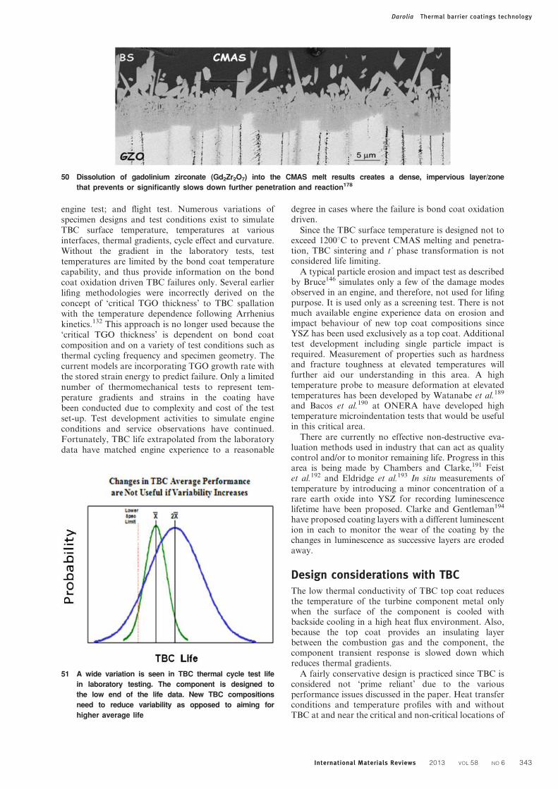
engine test; and flight test. Numerous variations ofspecimen designs and test conditions exist to simulateTBC surface temperature, temperatures at variousinterfaces, thermal gradients, cycle effect and curvature.Without the gradient in the laboratory tests, testtemperatures are limited by the bond coat temperaturecapability, and thus provide information on the bondcoat oxidation driven TBC failures only. Several earlierlifing methodologies were incorrectly derived on theconcept of ‘critical TGO thickness’ to TBC spallationwith the temperature dependence following Arrheniuskinetics.132 This approach is no longer used because the‘critical TGO thickness’ is dependent on bond coatcomposition and on a variety of test conditions such asthermal cycling frequency and specimen geometry. Thecurrent models are incorporating TGO growth rate withthe stored strain energy to predict failure. Only a limitednumber of thermomechanical tests to represent tem-perature gradients and strains in the coating havebeen conducted due to complexity and cost of the testset-up. Test development activities to simulate engineconditions and service observations have continued.Fortunately, TBC life extrapolated from the laboratorydata have matched engine experience to a reasonable
degree in cases where the failure is bond coat oxidationdriven.
Since the TBC surface temperature is designed not toexceed 1200uC to prevent CMAS melting and penetra-tion, TBC sintering and t’ phase transformation is notconsidered life limiting.
A typical particle erosion and impact test as describedby Bruce146 simulates only a few of the damage modesobserved in an engine, and therefore, not used for lifingpurpose. It is used only as a screening test. There is notmuch available engine experience data on erosion andimpact behaviour of new top coat compositions sinceYSZ has been used exclusively as a top coat. Additionaltest development including single particle impact isrequired. Measurement of properties such as hardnessand fracture toughness at elevated temperatures willfurther aid our understanding in this area. A hightemperature probe to measure deformation at elevatedtemperatures has been developed by Watanabe et al.189
and Bacos et al.190 at ONERA have developed hightemperature microindentation tests that would be usefulin this critical area.
There are currently no effective non-destructive eva-luation methods used in industry that can act as qualitycontrol and/or to monitor remaining life. Progress in thisarea is being made by Chambers and Clarke,191 Feistet al.192 and Eldridge et al.193 In situ measurements oftemperature by introducing a minor concentration of arare earth oxide into YSZ for recording luminescencelifetime have been proposed. Clarke and Gentleman194
have proposed coating layers with a different luminescention in each to monitor the wear of the coating by thechanges in luminescence as successive layers are erodedaway.
Design considerations with TBCThe low thermal conductivity of TBC top coat reducesthe temperature of the turbine component metal onlywhen the surface of the component is cooled withbackside cooling in a high heat flux environment. Also,because the top coat provides an insulating layerbetween the combustion gas and the component, thecomponent transient response is slowed down whichreduces thermal gradients.
A fairly conservative design is practiced since TBC isconsidered not ‘prime reliant’ due to the variousperformance issues discussed in the paper. Heat transferconditions and temperature profiles with and withoutTBC at and near the critical and non-critical locations of
50 Dissolution of gadolinium zirconate (Gd2Zr2O7) into the CMAS melt results creates a dense, impervious layer/zone
that prevents or significantly slows down further penetration and reaction178
51 A wide variation is seen in TBC thermal cycle test life
in laboratory testing. The component is designed to
the low end of the life data. New TBC compositions
need to reduce variability as opposed to aiming for
higher average life
Darolia Thermal barrier coatings technology
International Materials Reviews 2013 VOL 58 NO 6 343

the component dictate specific locations where TBC isapplied and its thickness. To utilise TBC to a greaterextent, TBC performance in the field is being analysedand related to laboratory data.
Maximum allowable bond coat temperature based onbond coat capability for a specific engine mission cycleand life requirements and overhaul interval is the firstdesign consideration. Calcium–magnesium–alumino-silicate melting temperature of y1240uC sets the uppertemperature limit for the top coat. In areas, prone toimpact, design has considered the maximum allowablebond coat temperature as the limit to avoid rapidoxidation of the coating and the underlying substrate. Inrotating components such as blades, TBC thickness thatranges between 100 and 250 mm is kept to a minimumsufficient to meet mission requirements to avoidexcessive inertial loads due to the extra mass. Onstationary components, such as shrouds and combus-tors, the mass is less critical and much thicker layers canbe used. Thermal barrier coating thickness on thesecomponents can range from 250 to 1000 mm.
Based on the field observations and laboratoryexperiments, it has been assumed that TBC willeventually fail. Thermal barrier coatings do not provideself-renewing protection. When TBC spalls, the thermalprotection is lost unlike environmental coatings used inturbines where a protective scale such as aluminareforms. Thermal barrier coating is stripped off the fieldreturned blades and reapplied if the blade is serviceable.The design practice has considered the following factors:when and at what location of the blade TBC spalls, typeof TBC failure mode (thermal/engine cycle related,particle erosion, impact damage or CMAS induced)determined by visual and microstructural failure analy-sis, and estimated temperature profiles at the damagedlocations.
Fortunately, the majority of the failure modes andtheir specific locations have been reasonably predictable.Temperature rise in the component is calculated at thelocations where TBC is missing or thinned out. Design
52 Scatter in TBC life with identical specimens (substrate, bond coat, top coat, processing and tests are identical).
Variation comes potentially from post-deposition heat treatment conditions (furnace type, contamination from furnace
walls, temperature and vacuum level)
53 Thermal cycle furnace test buttons (with NiAlCrZr
bond coat only) show variation in surface colour aris-
ing from specimen locations in the deposition cham-
ber using the same evaporation target. The coating
depositions were aimed to have identical NiAlCrZr
bond coat composition
Darolia Thermal barrier coatings technology
344 International Materials Reviews 2013 VOL 58 NO 6

iterations involve TBC spall size or remaining TBCthickness, altered heat transfer and heat flux character-istics. Certain specific locations of the blades (e.g.leading edge) are designed without taking into accountthe benefit of the insulating properties of TBC, since it isdifficult to predict and avoid TBC loss due to largeimpacting particles. In some cases, the leading edgecurvature of the blade has been redesigned to minimiseimpact damage.
Conclusions and future directionsApplication of TBC is one of the major developments inturbine industry that has revolutionised how turbinecomponents are designed. The surface temperatures ofthe components can potentially be increased by as highas 200uC. The temperature benefit surpasses othermaterial technologies advances including single crystalNi based superalloys achieved over a 30 year period.Thermal barrier coatings have become an integralpart of turbine designs requiring higher efficiency,performance and reduced emissions and noise. Ther-mal barrier coating applications continue to increase oncomponents in the propulsion and power generationturbines. In future, CMC components will also dependon TBC. Thermal barrier coatings have evolved fromjust simple insulating layers for temperature reduction tocomplex designs. However, the turbine designers have alove and hate relationship with TBC because ofunacceptable scatter in laboratory and engine perfor-mance, even with the baseline YSZ TBC due to a varietyof reasons mostly related to processing, and issuesrelated to damage by the particulates in the turbineoperating environment. The scatter in performancedictates that turbine components should be designed tothe lowest spectrum of the scatter band. Enhancedreliability should lead to deriving greater TBC benefits.
While our understanding of mechanisms governingTBC performance has improved significantly afterextensive research and development over the past twodecades, no clear top coat composition superior to YSZhas been developed; balance of properties being an issue.The baseline top coat composition developed at NASAcontinues to be used. It was essentially a mother nature’sgift after a short development effort mainly at NASAbased on the knowledge of bulk oxides used in industrialapplications.
Modifications to existing EB-PVD and APS processessuch as DVC, directed vapour deposition and suspensionplasma spray have been developed for process efficiency,cost reduction, and composition and microstructuraluniformity, control and flexibility. These processes areincreasingly being used. Critical need still exists for betterprocess controls with online sensors to avoid infantmortality, reduce scatter and improve TBC reliability.Higher temperature applications requiring CMAS relateddamage mitigation as well as microstructure and phasestability will add to composition and process complexitywith added costs that will need to be balanced with TBCperformance requirements for a specific application.
New bond coat compositions have been developed forslow TGO growth, higher temperature and/or longerservice life capabilities, reduced interdiffusion andreduction/elimination of platinum group metals. Thesenewly developed bond coats are being introduced intoservice. There is still a need to minimise use of expensive
elements such as Pt, Re, Ta and Ru. Long termavailability of the rare earth elements is also a concernin the industry. Bond coat development effort willcontinue for further optimisation of TGO and reducedinterdiffusion with the newer generation of Ni basedsuperalloys. The maximum bond coat temperature willstill be limited by the temperature capability of theunderlying alloy since there is minimal thermal gradientbetween the bond coat and the substrate. Life predic-tion, validation, and oxidation and hot corrosion teststhat simulate engine behaviour will continue to bepursued. Development efforts for effective diffusionbarriers will continue. This area could prove to be a holygrail.
The ‘low k TBC’ compositions will most likely requirean under layer of YSZ because of the chemicalincompatibility with TGO. This will add to processcomplexity and cost. The erosion and impact resistanceof the ‘low k TBC’ compositions is inferior to YSZ TBCas demonstrated in laboratory and component tests.Validation of laboratory data with engine tests isrequired. Currently, limited engine experience exists.
Development efforts have continued to make TBC‘prime reliant’. Prime reliance will require elimination ofcoating process variability, consistency in quality andperformance over time and a long and predictable life.Calcium–magnesium–alumino-silicate caused damagemodes have limited TBC surface temperature toy1200uC. Calcium–magnesium–alumino-silicate miti-gation solutions are the most critical development needs,and will continue to challenge materials scientists. Inauthor’s opinion, CMAS can become TBC’s Achilles’heel. Mitigation results with rare earth zirconates arevery promising. Validation with engine tests needs tocontinue. Thermal barrier coating thinning by particleerosion can perhaps be addressed by experience baseddesign practices but impact events are unpredictable,and fail safe designs need to be developed. Furtherdevelopment of tailored TBC microstructures involvingmulti- or modulated layers should play an importantrole in combating impact damage caused by impingingparticles. Additional test development including singleparticle impact is required. Measurement of propertiessuch as hardness and fracture toughness at elevatedtemperatures will further aid our understanding in thisarea. Embedded thermographic phosphors for tempera-ture and wear sensing will be used for specialised missioncritical applications.
The scientific understanding of TBC systems hasbenefited from collaboration between industry, govern-ment laboratories and universities for the last decade.Unfortunately, such collaborations have slowed, at leastin United States. The collaborations need to continuebecause the future TBC systems for higher temperatureapplications will most likely be highly complex incor-porating multifunctional multilayers requiring multi-disciplinary efforts. The challenge will be to develop costeffective TBC systems with balanced properties. As theTBC surface temperature is increased, issues such asphase stability, densification and microstructuralchanges will affect TBC performance particularly,spallation behaviour. Future TBC research will involve,in addition to composition and process development, abetter understanding of failure mechanisms, life predic-tion modelling, more effective use of sensors, perhaps
Darolia Thermal barrier coatings technology
International Materials Reviews 2013 VOL 58 NO 6 345

imbedded, and non-destructive evaluation methods forquality control during TBC manufacture, and assessingthe remaining TBC life. Improved laboratory andcomponent tests including thermomechanical and ther-mochemical–mechanical tests simulative of engine oper-ating conditions and associated failure mechanisms willhelp life prediction and component designs that takeadvantage of TBC to the fullest extent.
Acknowledgements
This review has attempted to capture contributions of alarge number of researchers. I would like to acknowl-edge many of my colleagues at GE Aviation and GEGlobal Research, especially Joe Rigney, Scott Walston,Dave Wortman, Ken Wright, Curt Johnson, DonLipkin, J.-C. Zhao (currently at the Ohio State Uni-versity), Ming Fu, Mark Gorman and Ben Nagaraj.Collaborations with Professors Tony Evans (Universityof California at Santa Barbara, UCSB), Carlos Levi(UCSB), David Clarke (UCSB), Kevin Hemker (JohnsHopkins University), Brian Gleeson (University ofPittsburgh), Arthur Heuer (Case Western ReserveUniversity), Jerry Meier (University of Pittsburgh),Fred Pettit (University of Pittsburgh), Dr Bob Miller(NASA), Dr Dongming Zhu (NASA) and Dr UweSchulz (DLR, Germany) are greatly appreciated. DrSteve Fishman (retired, Office of Naval Research) washighly instrumental in University collaborations. Muchof my thoughts and insights were obtained from suchcollaborations. This paper reflects much of the researchconducted under these collaborations. Special thanksto Drs Carlos Levi, Richard Wellman (CranfieldUniversity), Uwe Schulz and Dongming Zhu forallowing me to use figures from their published andunpublished work.
References1. C. G. Levi: Curr. Opin. Solid State Mater. Sci., 2004, 8, 77–91.
2. D. R. Clarke and C. G. Levi: Annu. Rev. Mater. Res., 2003, 33,
383–417.
3. N. P. Padture, M. Gell and E. H. Jordan: Science, 2002, 296, 280–
284.
4. M. Peters, B. Saruhan-Brings and U. Schulz: Proc. CEAS 2009
European Air and Space Conf., Manchester, UK, October 2009,
CEAS, 1–9.
5. B. Gleeson: J. Propul. Power, 2006, 22, 375–383.
6. R. Nicholls: MRS Bull., 2003, 28, 659–670.
7. J. A. Feuerstein, J. Knapp, T. Taylor, A. Ashray, A. Bolcavage
and N. Hitchman: J. Therm. Spray Technol., 2008, 17, (2), 199–
213.
8. A. G. Evans, D. R. Clarke and C. G. Levi: J. Eur. Ceram. Soci.,
2008, 28, (7), 1405–1419.
9. A. G. Evans, D. R. Mumm, J. W. Hutchinson, G. H. Meier and
F. S. Pettit: Prog. Mater. Sci., 2001, 46, 505–553.
10. A. H. Heuer, D. B. Hovis, J. L. Smialek and B. Gleeson: J. Am.
Ceram. Soc., 2011, 94, s146–s153.
11. N. Claussen, M. Ruhle and A. H. Heuer (eds.): ‘Science and
technology of zirconia II’; 1984, Columbus, OH, The American
Ceramic Society.
12. S. Somiya, N. Yamamoto and H. Yanagida (eds.): ‘Science and
technology of zirconia III’; 1988, Westerville, OH, The American
Ceramic Society.
13. S. Badwal, M. J. Bannister and R. H. J. Hannink (eds.): ‘Science
and technology of zirconia V’; 1993, Lancaster, Basel, Tech-
nomatic Publishing.
14. M. J. Stiger, N. M. Yanar, R. W. Jackson, S. J. Laney, F. S.
Pettit, G. H. Meier, A. S. Gandhi and C. G. Levi: Metall. Mater.
Trans. A, 2007, 38A, (4), 848–857.
15. J. A. Krogstad, S. Kramer, D. M. Lipkin, C. A. Johnson, D. R.
G. Mitchell, J. M. Cairney and C. G. Levi: J. Am. Ceram. Soc.,
2011, 94, S168–S177.
16. N. R. Rebollo, A. S. Gandhi and C. G. Levi: in ‘High temperature
corrosion and materials chemistry IV’, (ed. E. Opila et al.), 431–
442; 2003, Pennington, NJ, Electrochemical Society.
17. J. Chevalier, L. Gremillard, A. Virkar and D. R. Clarke: J. Am.
Ceram. Soc., 2009, 92, (9), 1901–1920.
18. S. Stecura: Am. Ceram. Soc. Bull., 1977, 56, 1082–1085.
19. S. Stecura: Adv. Ceram. Mater., 1986, 1, (1), 68–76.
20. S. Stecura: Thin Solid Films, 1987, 150, 15–40.
21. R. P. Ingel, D. Lewis, B. A. Bender and R. W. Rice: in ‘Advances
in ceramics’, Vol. 12, ‘Science and technology of zirconia II’, (ed.
N. Claussen et al.), 408–414; 1984, Columbus, OH, The American
Ceramic Society.
22. A. V. Virkar and R. L. K. Matsumoto: J. Am. Ceram. Soc., 1986,
69, C224–C226.
23. A. V. Virkar: Key Eng. Mater., 1998, 153–154, 183–210.
24. D. Baither, M. Bartsch, B. Baufeld, A. Tikhonovsky, F. A. M.
Ruhle and U. Messerschmidt: J. Am. Ceram. Soc., 2001, 84, (8),
1755–1762.
25. C. Mercer, J. R. Williams, D. R. Clarke and A. G. Evans: Proc. R.
Soc. A: Mathemat. Phys. Eng. Sci., 2007, 463, (2081), 1393–1408.
26. S. Sampath: Int. J. Mater. Prod. Technol., 2009, 35, (3/4), 425–
448.
27. S. Sampath, V. Srinivasan, A. Valarezo, A. Vaidya and T. Streibl:
J. Therm. Spray Technol., 2009, 18, (2), 243–255.
28. D. V. Rigney, R. Viguie, D. J. Wortman and D. W. Skelly:
J. Therm. Spray Technol., 199, 6, 167–175.
29. T. A. Taylor: ‘Thermal barrier coating for substrates and process
for producing it’, US Patent 5,073,433, 1991.
30. D. D. Hass, P. A. Parrish and H. N. G. Wadley: J. Vac. Sci.
Technol. A, 1998, 16A, 3396–3401.
31. D. D. Hass, A. J. Slifka and H. N. G. Wadley: Acta. Mater., 2001,
49, 973–983.
32. D. D. Hass, J. F. Groves and H. N. G. Wadley: Surf. Coat.
Technol., 2001, 85, 146–147.
33. N. P. Padture, K. W. Schlichting, T. Bhatia, A. Ozturk,
B. Cetegen, E. H. Jordan, M. Gell, S. Jiang, T. D. Xiao, P. R.
Strutt, E. Garcia, P. Miranzo and M. I. Osendi: Acta Mater.,
2001, 49, 2251–2257.
34. T. Bhatia, A. Ozturk, B. Cetegen, L. Xie, E. H. Jordan, M. Gell,
X. Ma and P. Padture: J. Mater. Res., 2002, 17, 2363–2372.
35. M. Gell, L. Xie, X. Ma, E. H. Jordan and N. P. Padture: Surf.
Coat. Technol., 2004, 97, 177–178.
36. A. Killinger, R. Gadow, G. Mauer, A. Guignard, R. Vaßen and
D. Stover: J. Therm. Spray Technol., 2011, 20, (4), 677–695.
37. B. A. Pint, J. A. Haynes, K. L. More, J. H. Schneibel, Y. Zhang
and I. G. Wright: in ‘Superalloys 2008’, (ed. R. C. Reed et al.),
641–650; 2008, Warrendale, PA, The Minerals, Metals and
Materials Society.
38. M. P. Brady, B. Gleeson and I. G. Wright: JOM, 2000, 52, (1),
16–21.
39. B. A. Pint: Mater. Sci. Forum, 2011, 696, 57–62.
40. B. A. Pint, K. L. More and I. G. Wright: Oxid. Met., 2003, 59,
(3–4), 257–283.
41. Y. Cadoret, D. Monceau, M.-P. Bacos, P. Josso, V. Maurice and
P. Marcus: Oxid. Met., 2005, 64, (3–4), 185–205.
42. L. Hu, D. B. Hovis and A. H. Heuer: Oxid. Met., 2010, 73, (1–2),
275–288.
43. N. M. Yanar, F. S. Pettit and G. H. Meier: Metall. Mater. Trans.
A, 2006, 37A, 1563–1580.
44. N. M. Yanar, G. H. Meier and F. S. Pettit: Scr. Mater., 2002, 46,
325–330.
45. J. A. Nesbitt, B. Gleeson, D. Sordelet and C. A. Barrett: Mater.
Sci. Forum, 2003, 209, 426–432.
46. J. G. Smeggil, A. W. Funkenbush and N .S. Bornstein: Metall.
Mater. Trans. A, 1986, 7A, 923–932.
47. J. L. Smialek: Metall. Mater. Trans. A, 1991, 22A, 739–752.
48. B. A. Pint, I. G. Wright, W. Y. Lee, Y. Zhang, K. Prußner and
K. B. Alexander: Mater. Sci. Eng. A, 1998, A245, 201–211.
49. J. A. Haynes, B. A. Pint, K. L. More, Y. Zhang and I. G. Wright:
Oxid. Met., 2002, 58, 513–544.
50. R. Janakiraman, G. H. Meier and F. S. Pettit: in ‘Cyclic oxidation
of high temperature materials’, (ed. M. Schutze and W. J.
Quadakkers), 38–62; 1999, London, European Federation of
Corrosion Publications.
51. J. L. Smialek, C. A. Barrett and J. C. Schaeffer: in ‘ASM
handbook’, 589–602; 1997, Materials Park, OH, ASM
International.
Darolia Thermal barrier coatings technology
346 International Materials Reviews 2013 VOL 58 NO 6

52. W. J. Quadakkers, A. K. Tyagi, D. Clemens, R. Anton and
L. Singheiser: in ‘Elevated temperature coatings: science and
technology III’, (ed. J. M. Hampikian and N. B. Dahotre), 119–
130; 1999, Warrendale, PA, TMS.
53. P. Y. Hou and K. Priimak: Oxid. Met., 2005, 63, 113–130.
54. J. L. Smialek: JOM, 2000, 52, 22–26.
55. T. Izumi and B. Gleeson: Mater. Sci. Forum, 2006, 221, 522–523.
56. S. Hayashi, S. I. Ford, D. J. Young, D. J. Sordelet, M. F. Besser
and B. Gleeson: Acta Mater., 2005, 53, 3319–3328.
57. V. K. Tolpygo, D. R. Clarke and K. S. Murphy: Metall. Mater.
Trans. A, 2001, 32A, 1467–1478.
58. V. K. Tolpygo and D. R. Clarke: Surf. Coat. Technol., 2005, 200,
1276–1281.
59. V. K. Tolpygo and D. R. Clarke: Mater. High Temper., 2000, 17,
(1), 59–70.
60. R. Darolia: ‘Post-deposition oxidation of a nickel-base superalloy
protected by a thermal barrier coating’, US Patent 6,607.611,
2003.
61. B. Gleeson: Unpublished work presented at Thermal Barrier
Coatings III, ECI Conference, 2011, at Irsee, Germany.
62. W. S. Walston, J. C. Schaeffer and W. H. Murphy: in ‘Superalloys
1996’, (ed. R. D. Kissinger et al.), 9–18; 1996, Warrendale, PA,
TMS.
63. D. S. Rickerby and R. G. Wing: ‘Thermal barrier coating for a
superalloy article and a method of application thereof’, US Patent
5,942,337, 1999.
64. D. S. Rickerby, S. R. Bell and R. G. Wing: ‘Article including
thermal barrier coated superalloy substrate’, US Patent 5,981,091,
1999.
65. B. Gleeson, W. Wang and D. J. Sordelet: ‘High temperature
coatings with Pt metal modified gamma-Ni z gamma9-Ni3Al
alloy compositions’, US Patent 7,273,662, 2007.
66. S. Hayashi, W. Wang, D. J. Sordelet and B. Gleeson: Metall.
Mater. Trans. A, 2005, 36A, 1769–1775.
67. R. Darolia: ‘Bond coat for a thermal barrier coating system and
method therefor’, US Patent 6,255,001, 2001.
68. R. Darolia, J. D. Rigney and R. G. Grylls: ‘Bond coat for a
thermal barrier coating system and systems therewith’, US Patent
6,291,084, 2001.
69. J. D. Rigney, R. Darolia, W. S. Walston and R. R. Corderman:
‘Bond coat for a thermal barrier coating system and systems
therewith’, US Patent 6,153,313, 2000.
70. J. A. Pfaendtner, J. R. Rigney, R. Darolia, R. R. Corderman and
R. A. Nardi: ‘Nickel aluminide coating and coating systems
formed therewith’, US Patent 6,620,524, 2003.
71. R. Darolia and J. D. Rigney: ‘Nickel-base superalloy article with
rhenium-containing protective layer, and its preparation’, US
Patent 6,461,746, 2002.
72. R. Darolia and W. S. Walston: in ‘Structural intermetallics 1997’,
(ed. M. V. Nathal et al.), 585–594; 1997, Warrendale, PA, TMS.
73. W. S. Walston, R. D. Field, J. R. Dobbs, D. F. Lahrman and
R. Darolia: in ‘Structural intermetallics’, (ed. R. Darolia et al.),
523–532; 1993, Warrendale, PA, TMS.
74. R. Darolia, W. S. Walston and M. V. Nathal: in ‘Superalloys
1996’, (ed. R. D. Kissinger et al.), 561–570; 1996, Warrendale, PA,
TMS.
75. I. T. Spitsberg, R. Darolia, M. R. Jackson, J.-C. Zhao and J. C.
Schaeffer: ‘Diffusion barrier layer’, US Patent 6,306,524 B1, 2001.
76. J.-C. Zhao, M. R. Jackson, R. J. Grylls and R. Darolia: ‘Heat-
resistant Ru alloy coating for protection of superalloy substrates
in high temperature’, US Patent 6,720,088, 2004.
77. J.-C. Zhao and M. R. Jackson: ‘Diffusion barrier coatings, and
related articles and processes’, US Patent 6,746,782, 2004.
78. T. Narita, K. Z. Thosin, L. Fengqun, S. Hayashi, H. Murakami,
B. Gleeson and D. Young: Mater. Corros., 2005, 56, 923–929.
79. P. G. Klemens and M. Gell: Mater. Sci. Eng. A, 1998, A245, 143–
149.
80. D. R. Clarke: Surf. Coat. Technol., 2003, 163–164, 67–74.
81. R. Mevrel, J. Laizeta, A. Azzopardi, B. Leclercq, M. Poulain,
O. Lavigne and D. Demange: J. Eur. Ceram. Soc., 2004, 24, 3081–
3089.
82. B. Saruhan, U. Schulz and M. Bartsch: Key Eng. Mater., 2007,
333, 137–146.
83. U. Schulz, C. Leyens, K. Fritscher, M. Peters, B. Saruhan,
O. Lavigne, M. Dorvaux, M. Poulain, R. Mevrel and M. L.
Caliez: Aerospace Sci. Technol., 2003, 7, 73–80.
84. C. Leyens, U. Schulz and M. Peters: in ‘High temperature
coatings –science and technology IV’, (ed. N. B. Dahotre et al.),
61–76; 2001, Warrendale, PA, TMS.
85. M. Peters, C. Leyens, U. Schulz and W. Kaysser: Adv. Eng.
Mater., 2001, 3, (4), 193–204.
86. U. Schulz, S. G. Terry and C. G. Levi: Mater. Sci. Eng. A, 2003,
A360, 319–329.
87. U. Schulz, B. Saruhan, K. Fritscher and C. Leyens: Int. J. Appl.
Ceram. Technol., 2004, 1, (4), 302–315.
88. J. M. Cairney, N. R. Rebollo, M. Ruhle and C. G. Levi: Int. J.
Mater. Res., 2007, 98, (12), 1177–1187.
89. T. Kakuda, A. M. Limarga, T. D. Bennett and D. R. Clarke: Acta
Mater., 2009, 57, 2583–2591.
90. A. Azzopardi, R. Mevrel, B. Saint-Ramond, E. Olson and
K. Stiller: Surf. Coat. Technol., 2004, 177–178, 131–139.
91. R. B. Dinwiddie, S. C. Beecher, W. D. Porter and B. A. Nagaraj:
‘The effect of thermal aging on the thermal conductivity of plasma
sprayed and EB-PVD thermal barrier coatings’. 96-GT-282,
ASME, New York, USA, 1996.
92. M. J. Maloney, H. S. Achter and R. H. Barkalow: Proc. 1997
Thermal Barrier Coating Workshop, Cincinnati, OH, USA, May
1997, 41. NASA/CP-1998-207429, NASA Lewis Research Center,
Cleveland, OH.
93. D. S. Rickerby and Y. A. Tamarin: ‘Metallic article having a
thermal barrier coating and a method of application thereof’, US
Patent 6,025,078, 2009.
94. J. R. Nicholls, K. J. Lawson and D. S. Rickerby: Surf. Coat.
Technol., 2002, 151–152, 383–391.
95. J. R. Nicholls, K. J. Lawson, A. Johnstone and D. S. Rickerby:
Mater. Sci. Forum, 2001, 369, 595–606.
96. J. D. Rigney and R. Darolia: ‘Yttria-stabilized zirconia with
reduced thermal conductivity’, US Patent 6,586,115 B2, 2003.
97. U. Schulz, B. Saint-Ramond, O. Lavigne, P. Moretto,
A. Vanlieshout and A. Borger: Ceram. Eng. Sci. Proc., 2004, 25,
375–380.
98. D. Zhu and R. A. Miller: Ceram. Eng. Sci. Proc., 2002, 23, 457–
468.
99. D. Zhu and R. A. Miller: J. Therm. Spray Technol., 2000, 9, 175–
180.
100. D. Zhu and R. A. Miller: ‘Low conductivity and high toughness
tetragonal phase structured ceramic thermal barrier coatings’, US
Patent 7,700,508 B1, 2010.
101. D. Zhu and R. A. Miller: ‘Low conductivity and sintering
resistant thermal barrier coatings’, US Patent 6,812,176, 2004.
102. D. Zhu and R. A. Miller: Surf. Coat. Technol., 1998, 108–109,
114–120.
103. M. D. Gorman, I. Spitsberg, B. A. Boutwell, R. Darolia, R. W.
Bruce, V. S. Venkataramani, A. M. Thompson and A. Mogro-
Campera: ‘Ceramic compositions for low conductivity thermal
barrier coatings’, US Patent, 6,858,334, 2005.
104. J. Singh, D. E. Wolfe, R. A. Miller and D. M. Zhu: J. Mater. Sci.,
2004, 39, 1975–1985.
105. K. Matsumoto, Y. Itoh and T. Kameda: Sci. Technol. Adv.
Mater., 2003, 4, 153–158.
106. M. J. Maloney: ‘Thermal barrier coating systems and materials’,
US Patent 6, 117,560, 2000.
107. M. J. Maloney: ‘Thermal barrier coating systems and materials’,
US Patent 6,284,323, 2001.
108. M. J. Maloney: ‘Thermal barrier coating systems and materials’,
US Patent 6,177,200, 2001.
109. R. Vassen, X. Cao, F. Tietz, D. Basu and D. Stover: J. Am.
Ceram. Soc., 2000, 83, 2023–2028.
110. B. Saruhan, P. Francois, K. Fritscher and U. Schulz: Surf. Coat.
Technol., 2004, 182, 175–183.
111. M. J. Maloney: Unpublished work presented at Thermal Barrier
Coatings III, ECI Conference, 2011, at Irsee, Germany.
112. R. Subramanian: ‘Thermal barrier coating having high phase
stability’, US Patent 6, 258, 467, 2001.
113. N. E. Ulion, M. Trubelja, M. Maloney and D. Litton: ‘Thin 7YSZ
interfacial layer as cyclic durability (spallation) life enhancement
for low conductivity TBCs’, US Patent 7, 326, 470, 2008.
114. R. Darolia, I. Spitsburg, B. A. Boutwell, M. D. Gorman and
R. W. Bruce: ‘Thermal barrier coatings having lower layer for
improved adherence to bond coat’, US Patent 6, 887, 595, 2005.
115. R. M. Leckie, S. Kramer, M. Ruhle and C. G. Levi: Acta Mater.,
2005, 53, (11), 3281–3292.
116. O. Fabrichnaya and F. Aldinger: Zeitschrift Metallkund., 2004,
95, (1), 27–39.
117. R. Darolia, B. A. Movchan, R. E. Nerodenko, I. Spitsburg, D. J.
Wortman, J. D. Rigney and V. S. Venkatramani: US Patent 6,
808,799, 2004.
Darolia Thermal barrier coatings technology
International Materials Reviews 2013 VOL 58 NO 6 347

118. R. Darolia, B. A. Movchan, R. E. Nerodenko, I. Spitsburg and
D. J. Wortman: ‘Thermal barrier coating and process therefor’,
US Patent 7, 087,266, 2006.
119. J. D. Rigney and R. Darolia: ‘Thermally-stabilized thermal
barrier coating’, US Patent, 6,544,665, 2003.
120. J. F. Ackerman, V. S. Venkataramani, I. Spitsberg and
R. Darolia: ‘Article protected by thermal barrier coating having a
sintering inhibitor, and its fabrication’, US Patent 6, 887,588, 2005.
121. T. D. Sparks, P. A. Fuierer and D. R. Clarke: J. Am. Ceram. Soc.,
2010, 93, (4), 1136–1141.
122. C. Wan, T. D. Sparks, P. Wei and D. R. Clarke: J. Am. Ceram.
Soc., 2010, 93, 1457–1460.
123. D. A. Hirchfield, et al.: Proc. 4th Int. Sympos. on ‘Ceramic
materials and components for engines’, (ed. R. Carlson et al.),
372; 1992, London, Elsevier Applied Science.
124. V. K. Tolpygo and D. R. Clarke: Acta Mater., 2000, 48, (10),
3283–3293.
125. J. W. Hutchinson and A. G. Evans: Surf. Coat. Technol., 2002,
149, 179–184.
126. A. Rabiei and A. G. Evans: Acta Mater., 2000, 48, 3963–3976.
127. T. Xu, M. Y. He and A. G. Evans: Acta Mater., 2003, 51, 3807–3820.
128. V. K. Tolpygo and D. R. Clarke: Acta Mater., 2004, 52, 5115–5141.
129. J. A. Nychka, T. Xu, D. R. Clarke and A.G. Evans: Acta Mater.,
2004, 52, 2561–2568.
130. D. S. Balint and J. W. Hutchinson: J. Mech. Phys. Solids, 2005,
53, 949–973.
131. K. W. Schlichting, N. P. Padture, E. H. Jordan and M. Gell:
Mater. Sci. Eng. A, 2003, A342, 120–130.
132. N. S. Cheruvu, K. S. Chan and R. Viswanathan: Energy Mater.,
2006, 1, 33–47.
133. N. R. Rebollo, M. Y. He, C. G. Levi and A. G. Evans: Zeitschrift
Metallkund., 2003, 94, 171–179.
134. D. S. Balint and J. W. Hutchinson: Acta Mater., 2003, 51, 3965–
3983.
135. S. M. Meier, D. M. Nissley and K. D. Sheffler: ‘Thermal barrier
coating life prediction model development’. NASA CR-189111,
NASA, Cleveland, OH, USA, 1991.
136. R. A. Miller: J. Am. Ceram. Soc., 1984, 67, 517–521.
137. R. A. Miller: ‘Progress toward life modeling of thermal barrier
coatings for aircraft gas turbine engines’. Paper 87-ICE-18,
ASME, New York, USA, 1987.
138. S. Dryepondt and D. R. Clarke: Acta Mater., 2009, 57, 2321–2327.
139. S. Dryepondt and D. R. Clarke: Scr. Mater., 2009, 60, 917–920.
140. S. Dryepondt, J. Porter and D. R. Clarke: Acta Mater., 2009, 57,
1717–1723.
141. R. G. Hutchinson and J. W. Hutchinson: J. Am. Ceram. Soc.,
2011, 94, s85–s95.
142. B. Heeg, V. K. Tolpygo and D. R. Clarke: J. Am. Ceram. Soc.,
2011, 94, s112–s119.
143. P. K. Wright and A. G. Evans: Curr. Opin. Solid State Mater.
Sci., 1999, 4, 255–265.
144. P. K. Wright: Mater. Sci. Eng. A, 1998, A245, 191–200.
145. P. Morrell and D. S. Rickerby: ‘Thermal barrier coatings’, 20-1 to
20-9, AGARD report 823, Aalborg, Denmark, NATO, 1998.
146. R. W. Bruce: Tribol. Trans., 1998, 41, (4), 399–410.
147. R. G. Wellman and J. R. Nicholls: J. Phys. D: Appl. Phys., 2007,
40, R293–R305.
148. R. G. Wellman, M. J. Deakin and J. R. Nicholls: Tribol. Int.,
2005, 38, 798–804.
149. R. G. Wellman, J. R. Nicholls and K. Murphy: Wear, 2009, 267,
1927–1934.
150. R. J. L. Steenbakker, R. G. Wellman and J. R. Nicholls: Surf.
Coat. Technol., 2006, 201, (6), 2140–2146.
151. R. G. Wellman and J. R. Nicholls: Tribol. Int., 2008, 41, 657–662.
152. R. G. Wellman, M. J. Deakin and J. R. Nicholls: Wear, 2005, 258,
349–356.
153. A. G. Evans, N. A. Fleck, S. Faulhaber, N. Vermaak,
M. Maloney and R. Darolia: Wear, 2006, 260, 886–894.
154. M. Wang, N. A. Fleck and A. G. Evans: J. Am. Ceram. Soc.,
2011, 94, s160–s167.
155. X. Chen, R. Wang, N. Yao, A. G. Evans, J. W. Hutchinson and
R. W. Bruce: Mater. Sci. Eng. A, 2003, A352, (1–2), 221–231.
156. R. P. Ingel, D. Lewis, B. A. Bender and R. W. Rice: Communications
of the American Ceramic Society, C-150-152, 1982.
157. R. Darolia: Unpublished work.
158. W. S. Walston: in ‘Superalloys 2004’, (ed. K. A. Green et al.),
579–588; 2004, Warrendale, PA, TMS.
159. D. J. Kim and T. Y. Tien: J. Am. Ceram. Soc., 1991, 74, (12),
3061–3065.
160. D. J. Kim: J. Am. Ceram. Soc., 1990, 73, (1), 115–120.
161. T. A. Schaedler, R. Leckie, S. Kramer and A. G. Evans: J. Am.
Ceram. Soc., 2007, 90, (12), 3896–3901.
162. T. A. Schaedler, O. Fabrichnaya and C. G. Levi: J. Eur. Ceram.
Soc., 2008, 28, 2509–2520.
163. R. Darolia and J. D. Rigney: ‘Thermal barrier coating with
improved erosion and impact resistance’, US Patent
6,617,049,2003.
164. R. Darolia and J. D. Rigney: ‘Thermal barrier coating with
improved strength and fracture toughness’, US Patent 6, 663,
983,2003.
165. J. D. Rigney and R. Darolia: ‘Thermal barrier coating with
improved erosion and impact resistance and process therefor’, US
Patent 6,620,525,2003.
166. C. Eberl, X. Wang, D. S. Gianola, T. D. Nguyen, M. Y. He, A. G.
Evans and K. J. Hemker: J. Am. Ceram. Soc., 2011, 94, s120–s127.
167. J. R. Smith, Y. Jiang and A. G. Evans: Appl. Phys. Lett., 2008, 92,
141918.
168. W. Zhang, J. R. Smith and A. G. Evans: Phys. Rev. B, 2003, 67B,
245414.
169. J. R. Smith, X.-G. Wang and A. G. Evans: Phys. Rev. B, 2006,
74B, 081403.
170. R. Molins, I. Rouzou and P. Hou: Oxid. Met., 2006, 65, (3–4),
263–283.
171. P. Y. Hou: Annu. Rev. Mater. Res., 2008, 38, 275–298.
172. R. Darolia and W. S. Walston: ‘Fabrication of superalloy articles
having hafnium- or zirconium-enriched protective layer’, US
Patent 6, 190, 471,2001.
173. R. Darolia, B. Boutwell, B. T. Hazel, B. A. Nagaraj, J. D. Rigney
and R. D. Wustman: ‘Thermal barrier coating with modulated
grain structure and method therefor’, US Patent 7, 318, 955,
2008.
174. C. Mercer, S. Faulhaber, A. G. Evans and R. Darolia: Acta
Mater., 2005, 53, 1029–1039.
175. S. Kramer, S. Faulhaber, M. Chambers, D. R. Clarke, C. G. Levi,
J. W. Hutchinson and A. G. Evans: Mater. Sci. Eng. A, 2008,
A490, (1–2), 26–35.
176. A. G. Evans and J. W. Hutchinson: Surf. Coat. Technol., 2007,
201, 7905–7916.
177. S. Kramer, J. Yang, C. A. Johnson and C. G. Levi: J. Am. Ceram.
Soc., 2006, 89, 3167–3175.
178. W. C. Hasz, M. P. Borom and C. A. Johnson: ‘Protected thermal
barrier coating composite with multiple coatings’, US Patent 6,
261, 643,2001.
179. W. C. Hasz, M. P. Borom and C. A. Johnson: ‘Protection of TBC
with an impermeable barrier coating’, US Patent 5, 871,820, 1999.
180. W. C. Hasz, C. A. Johnson and M. P. Borom: ‘Protection
of TBC by sacrificial surface coating’, US Patent 5,660,885, 1997.
181. M. Borom, C. A. Johnson and L. A. Peluso: Surf. Coat. Technol.,
1996, 86–87, 116–128.
182. S. Kramer, J. Yang and C. G. Levi: J. Am. Ceram. Soc., 2008, 91,
576–583.
183. M.-P. Bacos, J.-M. Dorvaux, S. Landais, O. Lavigne, R. Mevrel,
M. Poulain, C. Rio and M.-H. Vidal-Setif: Aerospace Lab. J.,
Nov. 2011, (3), 1–14.
184. R. Darolia, B. A. Nagaraj, D. G. Konitzer, M. D. Gorman and
M. Fu: ‘Layered thermal barrier coatings containing lanthanide
series oxides for improved resistance to CMAS degradation’ US
patent application 20070160859, 2007.
185. A. Aygun, A. L. Vasiliev, N. P. Padture and X. Ma: Acta Mater.,
2007, 55, 6734–6745.
186. J. M. Drexler, K. Shinoda, A. L. Ortiz, D. Li, A. L. Vasiliev,
A. D. Gledhill, S. Sampath and N. P. Padture: Acta Mater., 2010,
58, 6835–6844.
187. R. Darolia and M. Fu: ‘Yttria containing thermal barrier coating
topcoat layer and method for applying the coating layer’, US
Patent 7,862,901, 2011.
188. R. Darolia: Unpublished work, 2006.
189. M. Watanabe, C. Mercer, C. G. Levi and A. G. Evans: Acta
Mater., 2004, 52, 1479–1487.
190. M.-P. Bacos, J.-M. Dorvaux, O. Lavigne, R. Mevrel, M. Poulain,
C. Rio and M.-H. Vidal-Setif: Aerospace Lab J., Nov. 2011, (3),
1–11.
191. M. D. Chambers and D. R. Clarke: Annu. Rev. Mater. Res., 2009,
39, 325–359.
192. J. P. Feist, A. L. Heyes and J. R. Nicholls: J. Aerospace Eng.,
2001, 215, 6333–6342.
193. J. I. Eldridge, T. J. Bencic, C. M. Spuckler, J. Singh and D. E.
Wolfe: J. Am. Ceram. Soc., 2006, 89, (10), 3246–3251.
194. D. R. Clarke and M. M. Gentleman: Surf. Coat. Technol., 2007,
202, 4–7.
Darolia Thermal barrier coatings technology
348 International Materials Reviews 2013 VOL 58 NO 6