Embed Size (px)
Citation preview

MEP COORDINATION MEP COORDINATION PROCEDURE MANUALPROCEDURE MANUAL
INTRODUCTIONINTRODUCTION
CSD (Combined Service Drawing) is a process that involves defining the CSD (Combined Service Drawing) is a process that involves defining the locations for compounds of building system; in what are often congested spaces, in locations for compounds of building system; in what are often congested spaces, in order to avoid interference and to comply with diverse design and operations criteria.order to avoid interference and to comply with diverse design and operations criteria.
Mechanical, Electrical and Plumbing (MEP) coordination is a major Mechanical, Electrical and Plumbing (MEP) coordination is a major challenge for complex buildings and industrial plants. It involves locating equipment challenge for complex buildings and industrial plants. It involves locating equipment and routing connecting elements for each system using a process of sequentially and routing connecting elements for each system using a process of sequentially comparing and overlaying transparent drawings of MEP system on light table to comparing and overlaying transparent drawings of MEP system on light table to detect spatial interference. detect spatial interference.

1.1. Heating Ventilation and Air Conditioning Heating Ventilation and Air Conditioning (HVAC)(HVAC)
SERVICES INVOLVED IN SERVICES INVOLVED IN COORDINATION COORDINATION(CSD)(CSD)
2.2. Plumbing (Drainage & Water Supply)Plumbing (Drainage & Water Supply)
3.3. Electrical Services (Power & Lighting)Electrical Services (Power & Lighting)
4.4. Fire Fire ProtectionProtection

Heating Ventilation and Air ConditioningHeating Ventilation and Air Conditioning
HVAC systems heat and cool air and water and distribute these fluids to building HVAC systems heat and cool air and water and distribute these fluids to building spaces to maintain desired conditions. HVAC systems generally include the following spaces to maintain desired conditions. HVAC systems generally include the following components:components:
1) A Heat-Generating System1) A Heat-Generating System
2) A Cooling System2) A Cooling System
for hand adjusting and/or automatic monitoring of the system operation. The HVAC for hand adjusting and/or automatic monitoring of the system operation. The HVAC system provides complete conditioning of the air, which also may include filtering out system provides complete conditioning of the air, which also may include filtering out dust and odors, freshening with outdoor air, adjustment of the temperature, and dust and odors, freshening with outdoor air, adjustment of the temperature, and modification of the relative humidity.modification of the relative humidity.
3) An Air-Handling System and3) An Air-Handling System and
4) A Control 4) A Control System System

Plumbing (Drainage & Water Supply)Plumbing (Drainage & Water Supply)
The plumbing system serves three primary functionsThe plumbing system serves three primary functions : :
1) C1) Collection and Disposal of Waste Waterollection and Disposal of Waste Water
2) 2) Distribution of Hot and Cold WaterDistribution of Hot and Cold Water
3) 3) Collection and Disposal of Storm waterCollection and Disposal of Storm water

Electrical Services (Power & Lighting)Electrical Services (Power & Lighting)
LIGHTING :LIGHTING :
In the lighting drawing we will take type of light & lumen’s of the light. Take distance between light to wall. Also take distance between light to light. Take a circuit those light’s with respect of depend on load. In every circuit we will take maximum 10 no’s of lights. We are using two type’s of installation method’s.
1) 1) Fall Ceiling typeFall Ceiling type
2) 2) Wall Mounted typeWall Mounted type
POWER:POWER:

The two primary objectives of the fire-protection system are to save lives and protect The two primary objectives of the fire-protection system are to save lives and protect property. property.
The design approach is to make the building fire resistant and to facilitate the speedy The design approach is to make the building fire resistant and to facilitate the speedy evacuation of occupants in case of a fire. Contrary to popular belief, this system can evacuation of occupants in case of a fire. Contrary to popular belief, this system can only retard fires during extreme emergencies.only retard fires during extreme emergencies.
Fire protection systems fall into one of four categories: Fire protection systems fall into one of four categories:
1) 1) WetWet
2) 2) DryDry
3) Pre-3) Pre-ActionAction
4) Deluge 4) Deluge
In wet systems, water is always under pressure in all pipes and In wet systems, water is always under pressure in all pipes and mains.mains.
In dry systems, pipes contain compressed air or nitrogen until the In dry systems, pipes contain compressed air or nitrogen until the opening of a sprinkler permits water flow. opening of a sprinkler permits water flow.
Pre-action systems are similar to dry systems, except that Pre-action systems are similar to dry systems, except that valves release water to the pipes before any sprinkler head valves release water to the pipes before any sprinkler head has opened. has opened.
In a deluge system, the sprinklers are open and all go off at once In a deluge system, the sprinklers are open and all go off at once
Fire Fighting SystemFire Fighting System
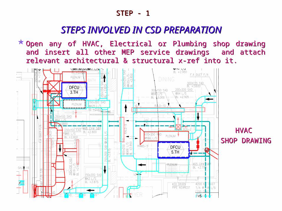
STEPS INVOLVED IN CSD PREPARATIONSTEPS INVOLVED IN CSD PREPARATIONOpen any of HVAC, Electrical or Plumbing shop drawing and insert all other MEP Open any of HVAC, Electrical or Plumbing shop drawing and insert all other MEP
service drawings and attach relevant architectural & structural x-ref into it.service drawings and attach relevant architectural & structural x-ref into it.
STEP - 1STEP - 1
HVAC HVAC
SHOP DRAWINGSHOP DRAWING
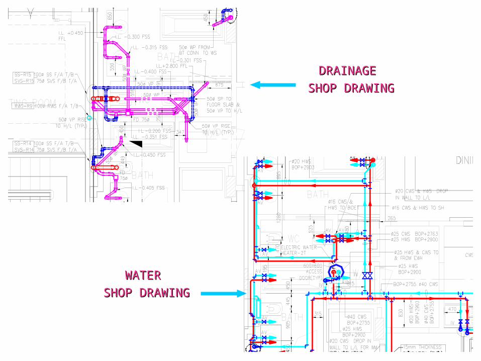
DRAINAGE DRAINAGE
SHOP DRAWINGSHOP DRAWING
WATER WATER
SHOP DRAWINGSHOP DRAWING

LIGHTING LIGHTING
SHOP DRAWINGSHOP DRAWING
POWERPOWER
SHOP DRAWINGSHOP DRAWING

FIRE FIGHTING FIRE FIGHTING
SHOP DRAWINGSHOP DRAWING

ARCHITECTUREARCHITECTURE
X-REFX-REF
STRUCTURALSTRUCTURAL
X-REFX-REF

After merging of all MEP Services together the drawing will be look like as figure After merging of all MEP Services together the drawing will be look like as figure shown below:shown below:

Remove all unnecessary entities, text, pipe supports and keep relevant data for Remove all unnecessary entities, text, pipe supports and keep relevant data for coordination purposes.coordination purposes.
STEP - 2STEP - 2
Unnecessary Entities in HVAC Service :Unnecessary Entities in HVAC Service :
1. All Abbreviations e.g. VD, 1. All Abbreviations e.g. VD, FDFD 2. Highlighted Text as Showing Below2. Highlighted Text as Showing Below
3. Volume Damper and Fire Damper at the place of dense 3. Volume Damper and Fire Damper at the place of dense area.area.
4. Tag Numbers Like (RALD-7, SALD-8, RWMS-3, 4. Tag Numbers Like (RALD-7, SALD-8, RWMS-3, DUC-3)DUC-3)
5. Duct Air Flow 5. Duct Air Flow ArrowsArrows 6. Duct Insulations6. Duct Insulations
7. All Hanging 7. All Hanging SupportsSupports 8. All 8. All DimensionsDimensions

Unnecessary Entities in Plumbing Service :Unnecessary Entities in Plumbing Service :
1. All Abbreviations e.g. 1. All Abbreviations e.g. RERE 2. All Riser Numbers2. All Riser Numbers
3. Highlighted Text as Showing 3. Highlighted Text as Showing BelowBelow
4. Pipe Designation e.g. 4. Pipe Designation e.g. Ø50 VP, Ø75 Ø50 VP, Ø75 WPWP 5. All 5. All DimensionsDimensions
DRAINAGE SERVICE :-DRAINAGE SERVICE :-
WATER SERVICE :-WATER SERVICE :-
1. All Abbreviations e.g. AV, IV, WHA1. All Abbreviations e.g. AV, IV, WHA
2. All Riser 2. All Riser NumbersNumbers 3. Insulation and Insulation 3. Insulation and Insulation TextText 4. All 4. All DimensionsDimensions
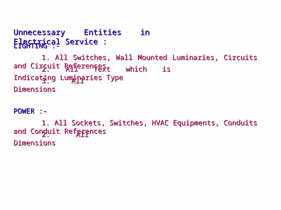
Unnecessary Entities in Electrical Service :Unnecessary Entities in Electrical Service :
1. All Switches, Wall Mounted Luminaries, Circuits and Circuit References1. All Switches, Wall Mounted Luminaries, Circuits and Circuit References
2. All Text which is Indicating Luminaries 2. All Text which is Indicating Luminaries TypeType 3. All 3. All DimensionsDimensions
LIGHTING :-LIGHTING :-
1. All Sockets, Switches, HVAC Equipments, Conduits and Conduit 1. All Sockets, Switches, HVAC Equipments, Conduits and Conduit ReferencesReferences2. All 2. All DimensionsDimensions
POWER :-POWER :-

Unnecessary Entities in Fire Fighting Service :Unnecessary Entities in Fire Fighting Service :
1. Tag Number Showing as 1. Tag Number Showing as BelowBelow
2. All Pipe Supports2. All Pipe Supports
3. All 3. All DimensionsDimensions

STEP - 3STEP - 3
Rearrange all texts in order to avoid overlaps and good presentation of the CSD Rearrange all texts in order to avoid overlaps and good presentation of the CSD drawing.drawing.
After completion of CSD presentation take printout of the drawing and color each After completion of CSD presentation take printout of the drawing and color each service manually with different colors. Then check and mark clashing areas.service manually with different colors. Then check and mark clashing areas.

STEP - 4STEP - 4
To avoid the clashing (hitting) change the levels for the services at the clashing To avoid the clashing (hitting) change the levels for the services at the clashing places.places.
Before Changing the LevelsBefore Changing the Levels After Changing the LevelsAfter Changing the Levels

STEP - 5STEP - 5
Study the plan and sections of relevant architectural drawings to ascertain Finish Study the plan and sections of relevant architectural drawings to ascertain Finish Floor Level (FFL), False Ceiling Level (FCL) and Roof Slab Levels.Floor Level (FFL), False Ceiling Level (FCL) and Roof Slab Levels.


STEP - 6STEP - 6
Check the riser locations in the below floor and upper floor drawing to match riser Check the riser locations in the below floor and upper floor drawing to match riser positions.positions.
Soil Pipe RiserSoil Pipe Riser
Waste Pipe RiserWaste Pipe Riser
Vent Pipe RiserVent Pipe Riser
Rain Water Pipe RiserRain Water Pipe Riser
FS RiserFS Riser
Duct RiserDuct Riser

STEP - 7STEP - 7
Prepare sectional drawings at the critical Prepare sectional drawings at the critical areas.areas.


STEP - 8STEP - 8
Prepare required number of view ports as per clients scale with relevant Prepare required number of view ports as per clients scale with relevant title blocks.title blocks.Check following instructions while preparing view Check following instructions while preparing view ports.ports.
1.1. Check Drawing Title, Drawing Check Drawing Title, Drawing Number, Date, Revision Number and Number, Date, Revision Number and Detailer & Checker Code is inserted Detailer & Checker Code is inserted correctlycorrectly
2.2. Check Key Plan, Revision Number, Check Key Plan, Revision Number, Date, Description, Detailer & Checker Date, Description, Detailer & Checker Code is inserted correctlyCode is inserted correctly

3.3. Check Drawing Title, Drawing Check Drawing Title, Drawing Number, Date, Revision Number and Number, Date, Revision Number and Detailer & Checker Code is inserted Detailer & Checker Code is inserted correctlycorrectly
4.4. Check LegendsCheck Legends

CSD OUTPUT DRAWINGCSD OUTPUT DRAWING
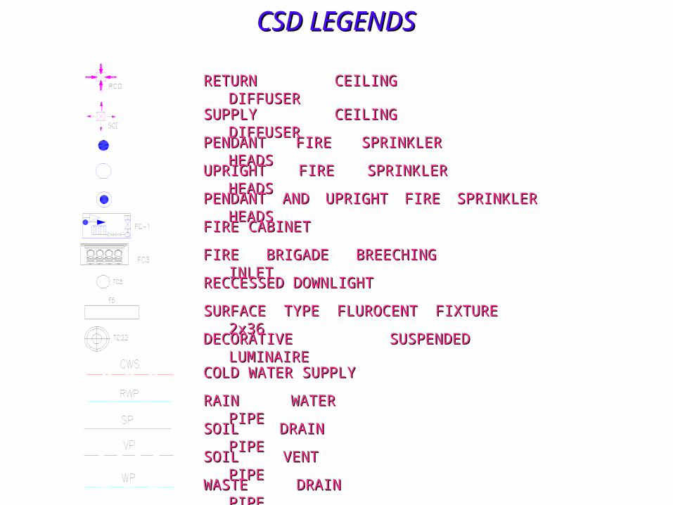
CSD LEGENDSCSD LEGENDS
RETURN CEILING RETURN CEILING DIFFUSERDIFFUSER
SUPPLY CEILING SUPPLY CEILING DIFFUSERDIFFUSER
PENDANT FIRE SPRINKLER PENDANT FIRE SPRINKLER HEADSHEADS
UPRIGHT FIRE SPRINKLER UPRIGHT FIRE SPRINKLER HEADSHEADS
PENDANT AND UPRIGHT FIRE SPRINKLER PENDANT AND UPRIGHT FIRE SPRINKLER HEADSHEADS
FIRE CABINETFIRE CABINET
FIRE BRIGADE BREECHING FIRE BRIGADE BREECHING INLETINLET
RECCESSED RECCESSED DOWNLIGHTDOWNLIGHT
SURFACE TYPE FLUROCENT FIXTURE SURFACE TYPE FLUROCENT FIXTURE 2x362x36
DECORATIVE SUSPENDED DECORATIVE SUSPENDED LUMINAIRELUMINAIRE
COLD WATER COLD WATER SUPPLYSUPPLY
RAIN WATER PIPERAIN WATER PIPE
SOIL DRAIN SOIL DRAIN PIPEPIPE
SOIL VENT PIPESOIL VENT PIPE
WASTE DRAIN WASTE DRAIN PIPEPIPE

CSD ABBREVATIONSCSD ABBREVATIONS
KEDKED -- KITCHEN EXTRACT DUCTKITCHEN EXTRACT DUCT
CHWSCHWS -- CHILLED WATER SUPPLYCHILLED WATER SUPPLY
CHWRCHWR -- CHILLED WATER CHILLED WATER RETURNRETURN
SADSAD -- SUPPLY AIR DIFFUSERSUPPLY AIR DIFFUSER
RADRAD -- RETURN AIR DIFFUSERRETURN AIR DIFFUSER
F/AF/A -- FROM FROM ABOVEABOVE
F/BF/B -- FROM FROM BELOWBELOW
T/AT/A -- TO ABOVETO ABOVE
T/BT/B -- TO TO BELOWBELOW
H/LH/L -- HIGH HIGH LEVELLEVEL
L/LL/L -- LOW LOW LEVELLEVEL
F.F.LF.F.L -- FINISHED FLOOR FINISHED FLOOR LEVELLEVEL
BOPBOP -- BOTTOM OF PIPEBOTTOM OF PIPE
BODBOD -- BOTTOM OF BOTTOM OF DUCTDUCT
BOUBOU -- BOTTOM OF BOTTOM OF UNITUNIT

TYPICAL PROBLEMS ENCOUNTERED DURING TYPICAL PROBLEMS ENCOUNTERED DURING COORDINATIONCOORDINATION
COORDINATION ISSUES WAYS TO AVOID OR RESOLVE
Graded plumbing lines interfering withductwork
· Drop ceiling grid· Move one component to side· Penetrate ductwork· Flatten ductwork· Drop ductwork below plumbing line· Split ductwork around plumbing line
Graded plumbing line interfering withstructural member
· Cope structural member· Penetrate structural member
Components interfering with accessspace for valves
· Move components away from valve
Ductwork interfering with lightingfixture removal clearance space
· Drop ceiling grid· Move ductwork away from lighting· Flatten ductwork
Vertical space not adequate to place allcomponents
· Drop ceiling grid· Place electrical conduit in floor slab· Use alternative ductwork shape
As ductwork drops below structuralelement, bottom of ductwork fallsbelow ceiling grid
· Drop ceiling grid· Flatten ductwork· Penetrate structural member
Components too close to structuralsystem, therefore not allowing properarea for fire proofing
· Move components down to allow forproper thickness of fire proofing
No access space for maintenance · Move components to sides to createaccess area
Component support systems interferewith other components
· Create common support systems for allsystems

INDICATORS FOR THE QUALITY OF MEP INDICATORS FOR THE QUALITY OF MEP CORDINATION EFFORTSCORDINATION EFFORTS
1.1. Minimize the number of fittings and Minimize the number of fittings and connections.connections.
2.2. Group and centralize similar systems.Group and centralize similar systems.
3.3. Group similar systems at same Group similar systems at same elevation.elevation.
4.4. Route systems on grid pattern, perpendicular to Route systems on grid pattern, perpendicular to building walls.building walls.
5.5. Minimize the number of diagonal lines.Minimize the number of diagonal lines.
6.6. Provide adequate access space for operations and Provide adequate access space for operations and maintenance.maintenance.
7.7. Reserve adequate space for future expansion.Reserve adequate space for future expansion.