Embed Size (px)
Citation preview
Model eCNA-5D-Cinema Automation
Installation and OperationManual
Version 1.052-02 : March 9, 2010

Table of Contents
1. Product Description . . . . . . . . . . . . . . . . . . . . . . . . . . . . . . . . . . . . . . . . . . . . . . . . . . . . 1
2. Enclosure . . . . . . . . . . . . . . . . . . . . . . . . . . . . . . . . . . . . . . . . . . . . . . . . . . . . . . . . . . . . 2
3. Configuring the Unit . . . . . . . . . . . . . . . . . . . . . . . . . . . . . . . . . . . . . . . . . . . . . . . . . . . . 3
3.1 Configuring the Main CPU Board . . . . . . . . . . . . . . . . . . . . . . . . . . . . . . . . . . . . . . . 33.2 Configuring Ethernet via the Serial Port . . . . . . . . . . . . . . . . . . . . . . . . . . . . . . . . . . 73.3 Configuring via the Web Browser . . . . . . . . . . . . . . . . . . . . . . . . . . . . . . . . . . . . . . 10
3.3.1 Setup . . . . . . . . . . . . . . . . . . . . . . . . . . . . . . . . . . . . . . . . . . . . . . . . . . . 113.3.2 Setup: Ethernet Network . . . . . . . . . . . . . . . . . . . . . . . . . . . . . . . . . . . . . . 113.3.3 Setup: Trigger Configuration . . . . . . . . . . . . . . . . . . . . . . . . . . . . . . . . . . . 133.3.4 Setup: Fault Behavior . . . . . . . . . . . . . . . . . . . . . . . . . . . . . . . . . . . . . . . . 153.3.5 Setup: Real Time Clock . . . . . . . . . . . . . . . . . . . . . . . . . . . . . . . . . . . . . . . 173.3.6 Setup: System Parameters . . . . . . . . . . . . . . . . . . . . . . . . . . . . . . . . . . . . . 183.3.7 Setup: Segment Names . . . . . . . . . . . . . . . . . . . . . . . . . . . . . . . . . . . . . . . 223.3.8 Setup: Remote Device Configuration . . . . . . . . . . . . . . . . . . . . . . . . . . . . . 233.3.9 I/O Boards . . . . . . . . . . . . . . . . . . . . . . . . . . . . . . . . . . . . . . . . . . . . . . . . 253.3.10 Setup: 39431/39445 House/Aux . . . . . . . . . . . . . . . . . . . . . . . . . . . . . . . . 263.3.11 Setup: Light Control . . . . . . . . . . . . . . . . . . . . . . . . . . . . . . . . . . . . . . . . 303.3.12 Setup: Zone Names . . . . . . . . . . . . . . . . . . . . . . . . . . . . . . . . . . . . . . . . . 303.3.13 Setup: QDC-400 Dimmer Boards . . . . . . . . . . . . . . . . . . . . . . . . . . . . . . . . 313.3.14 Setup: RVC-5 Card . . . . . . . . . . . . . . . . . . . . . . . . . . . . . . . . . . . . . . . . . 323.3.15 LVM-250 Voltage Monitor . . . . . . . . . . . . . . . . . . . . . . . . . . . . . . . . . . . . . 333.3.16 Administration . . . . . . . . . . . . . . . . . . . . . . . . . . . . . . . . . . . . . . . . . . . . 343.3.17 Setup: Backup or Restore eCNA-5 Configuration . . . . . . . . . . . . . . . . . . . . . 343.3.18 Setup: Device Firmware Update . . . . . . . . . . . . . . . . . . . . . . . . . . . . . . . . 373.3.19 Programs . . . . . . . . . . . . . . . . . . . . . . . . . . . . . . . . . . . . . . . . . . . . . . . . 393.3.20 Program and Macro Instructions . . . . . . . . . . . . . . . . . . . . . . . . . . . . . . . . 393.3.21 Setup: Program Editor . . . . . . . . . . . . . . . . . . . . . . . . . . . . . . . . . . . . . . . 463.3.22 Setup: Macro Editor . . . . . . . . . . . . . . . . . . . . . . . . . . . . . . . . . . . . . . . . . 47
4. Status . . . . . . . . . . . . . . . . . . . . . . . . . . . . . . . . . . . . . . . . . . . . . . . . . . . . . . . . . . . . 48
4.1 Status: Main Status . . . . . . . . . . . . . . . . . . . . . . . . . . . . . . . . . . . . . . . . . . . . . . . 484.1.1 Status and Fault Messages . . . . . . . . . . . . . . . . . . . . . . . . . . . . . . . . . . . . 49
4.2 Status: Network Monitor . . . . . . . . . . . . . . . . . . . . . . . . . . . . . . . . . . . . . . . . . . . . 514.3 Status: Local I/O Network . . . . . . . . . . . . . . . . . . . . . . . . . . . . . . . . . . . . . . . . . . . 524.4 Status: Ethernet Network . . . . . . . . . . . . . . . . . . . . . . . . . . . . . . . . . . . . . . . . . . . 544.5 Status: Event Log . . . . . . . . . . . . . . . . . . . . . . . . . . . . . . . . . . . . . . . . . . . . . . . . 544.6 Status: System Control Detail . . . . . . . . . . . . . . . . . . . . . . . . . . . . . . . . . . . . . . . . 554.7 Status: I/O Flag Detail . . . . . . . . . . . . . . . . . . . . . . . . . . . . . . . . . . . . . . . . . . . . . 56
5. CAI Serial Command Interface . . . . . . . . . . . . . . . . . . . . . . . . . . . . . . . . . . . . . . . . . . . 57
5.1 EVENT Command . . . . . . . . . . . . . . . . . . . . . . . . . . . . . . . . . . . . . . . . . . . . . . . . . 595.2 LOG Command . . . . . . . . . . . . . . . . . . . . . . . . . . . . . . . . . . . . . . . . . . . . . . . . . . . 605.3 CONFIGURATION Command . . . . . . . . . . . . . . . . . . . . . . . . . . . . . . . . . . . . . . . . . 615.4 STATUS Command . . . . . . . . . . . . . . . . . . . . . . . . . . . . . . . . . . . . . . . . . . . . . . . . 625.5 OUTPUT Command . . . . . . . . . . . . . . . . . . . . . . . . . . . . . . . . . . . . . . . . . . . . . . . . 645.6 READ CLOCK Command . . . . . . . . . . . . . . . . . . . . . . . . . . . . . . . . . . . . . . . . . . . . 665.7 SET CLOCK Command . . . . . . . . . . . . . . . . . . . . . . . . . . . . . . . . . . . . . . . . . . . . . . 675.8 REPORT ID Command . . . . . . . . . . . . . . . . . . . . . . . . . . . . . . . . . . . . . . . . . . . . . . 685.9 EXCHANGE STATUS Command . . . . . . . . . . . . . . . . . . . . . . . . . . . . . . . . . . . . . . . . 695.10 REPORT STATUS Command . . . . . . . . . . . . . . . . . . . . . . . . . . . . . . . . . . . . . . . . 735.11 EVENT Report . . . . . . . . . . . . . . . . . . . . . . . . . . . . . . . . . . . . . . . . . . . . . . . . . . 755.12 EVENT Log . . . . . . . . . . . . . . . . . . . . . . . . . . . . . . . . . . . . . . . . . . . . . . . . . . . . 775.13 Error Response Numbers . . . . . . . . . . . . . . . . . . . . . . . . . . . . . . . . . . . . . . . . . . . 855.14 Connect Error Response . . . . . . . . . . . . . . . . . . . . . . . . . . . . . . . . . . . . . . . . . . . 855.15 Checksum . . . . . . . . . . . . . . . . . . . . . . . . . . . . . . . . . . . . . . . . . . . . . . . . . . . . . 865.16 Command Summary . . . . . . . . . . . . . . . . . . . . . . . . . . . . . . . . . . . . . . . . . . . . . 875.17 Event Report Summary . . . . . . . . . . . . . . . . . . . . . . . . . . . . . . . . . . . . . . . . . . . 905.18 Event Log Summary . . . . . . . . . . . . . . . . . . . . . . . . . . . . . . . . . . . . . . . . . . . . . . 92

Table of Contents (continued)
6. System Block Diagram . . . . . . . . . . . . . . . . . . . . . . . . . . . . . . . . . . . . . . . . . . . . . . . . . 97
7. I/O Termination Board . . . . . . . . . . . . . . . . . . . . . . . . . . . . . . . . . . . . . . . . . . . . . . . . . 99
7.1 39490 House/Aux Termination Board . . . . . . . . . . . . . . . . . . . . . . . . . . . . . . . . . . . 997.2 39490 Termination Schedule . . . . . . . . . . . . . . . . . . . . . . . . . . . . . . . . . . . . . . . . 1017.3 39490 Board Dimensions . . . . . . . . . . . . . . . . . . . . . . . . . . . . . . . . . . . . . . . . . . . 1037.4 Termination Board Inputs . . . . . . . . . . . . . . . . . . . . . . . . . . . . . . . . . . . . . . . . . . 1047.5 Termination Board Outputs . . . . . . . . . . . . . . . . . . . . . . . . . . . . . . . . . . . . . . . . . 106
8. Power Supply . . . . . . . . . . . . . . . . . . . . . . . . . . . . . . . . . . . . . . . . . . . . . . . . . . . . . . . 107
eCNA-5 Cinema Automation
1EPRAD Incorporated, © 2010
1. Product Description
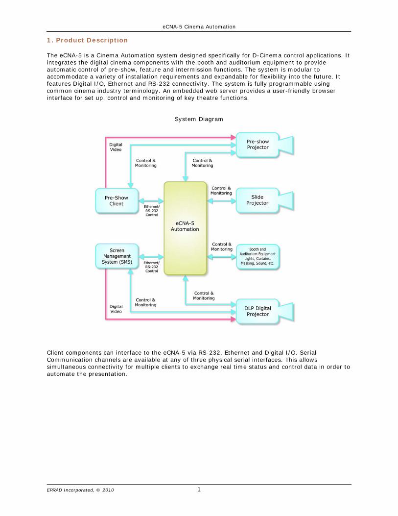
The eCNA-5 is a Cinema Automation system designed specifically for D-Cinema control applications. Itintegrates the digital cinema components with the booth and auditorium equipment to provideautomatic control of pre-show, feature and intermission functions. The system is modular toaccommodate a variety of installation requirements and expandable for flexibility into the future. Itfeatures Digital I/O, Ethernet and RS-232 connectivity. The system is fully programmable usingcommon cinema industry terminology. An embedded web server provides a user-friendly browserinterface for set up, control and monitoring of key theatre functions.
System Diagram
Client components can interface to the eCNA-5 via RS-232, Ethernet and Digital I/O. SerialCommunication channels are available at any of three physical serial interfaces. This allowssimultaneous connectivity for multiple clients to exchange real time status and control data in order toautomate the presentation.
eCNA-5 Cinema Automation
2EPRAD Incorporated, © 2010
2. Enclosure
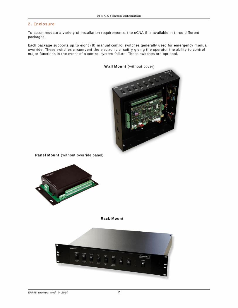
To accommodate a variety of installation requirements, the eCNA-5 is available in three differentpackages.
Each package supports up to eight (8) manual control switches generally used for emergency manualoverride. These switches circumvent the electronic circuitry giving the operator the ability to controlmajor functions in the event of a control system failure. These switches are optional.
Wall Mount (without cover)
Panel Mount (without override panel)
Rack Mount
eCNA-5 Cinema Automation
3EPRAD Incorporated, © 2010
3. Configuring the Unit
The eCNA-5 must be configured to operate on a network with various network devices and with theperipheral booth and auditorium equipment.
3.1 Configuring the Main CPU Board
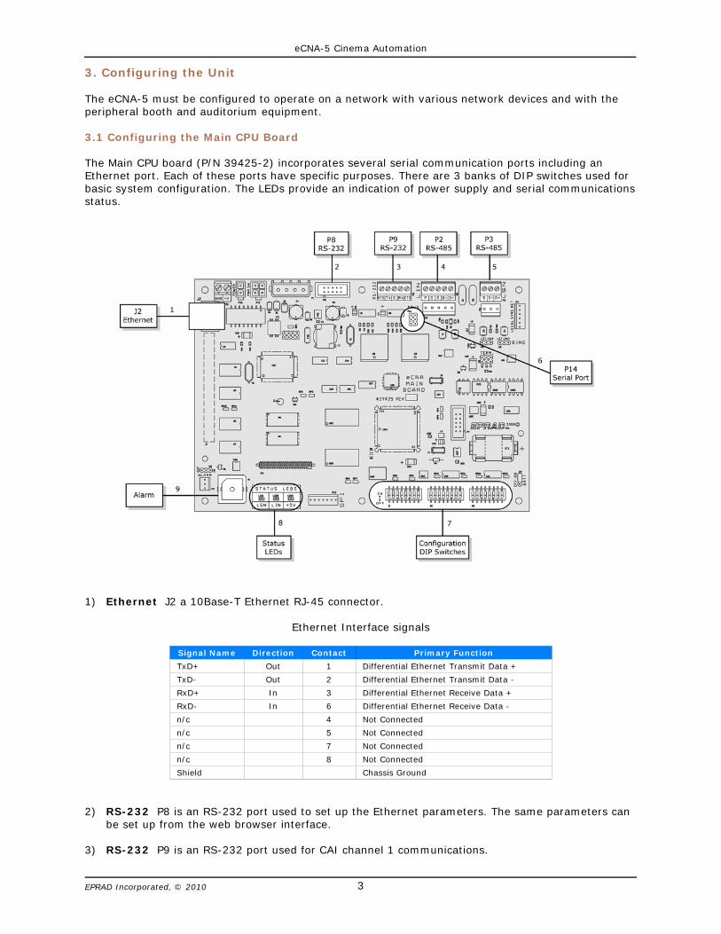
The Main CPU board (P/N 39425-2) incorporates several serial communication ports including anEthernet port. Each of these ports have specific purposes. There are 3 banks of DIP switches used forbasic system configuration. The LEDs provide an indication of power supply and serial communicationsstatus.
1) Ethernet J2 a 10Base-T Ethernet RJ-45 connector.
Ethernet Interface signals
Signal Name Direction Contact Primary Function
TxD+ Out 1 Differential Ethernet Transmit Data +
TxD- Out 2 Differential Ethernet Transmit Data -
RxD+ In 3 Differential Ethernet Receive Data +
RxD- In 6 Differential Ethernet Receive Data -
n/c 4 Not Connected
n/c 5 Not Connected
n/c 7 Not Connected
n/c 8 Not Connected
Shield Chassis Ground
2) RS-232 P8 is an RS-232 port used to set up the Ethernet parameters. The same parameters canbe set up from the web browser interface.
3) RS-232 P9 is an RS-232 port used for CAI channel 1 communications.
eCNA-5 Cinema Automation
4EPRAD Incorporated, © 2010
4) RS-485 P2 and P10 are the LIN (Local I/O Network) connections. Serial data and power supportthe termination boards, dimmer control and any other LIN devices.
5) RS-485 P3 and P11 are connectors for the isolated RS-485 port.
6) Serial Port P14 supports the CAI channel 3. It requires the optional 39446 RS-232 adapterboard.
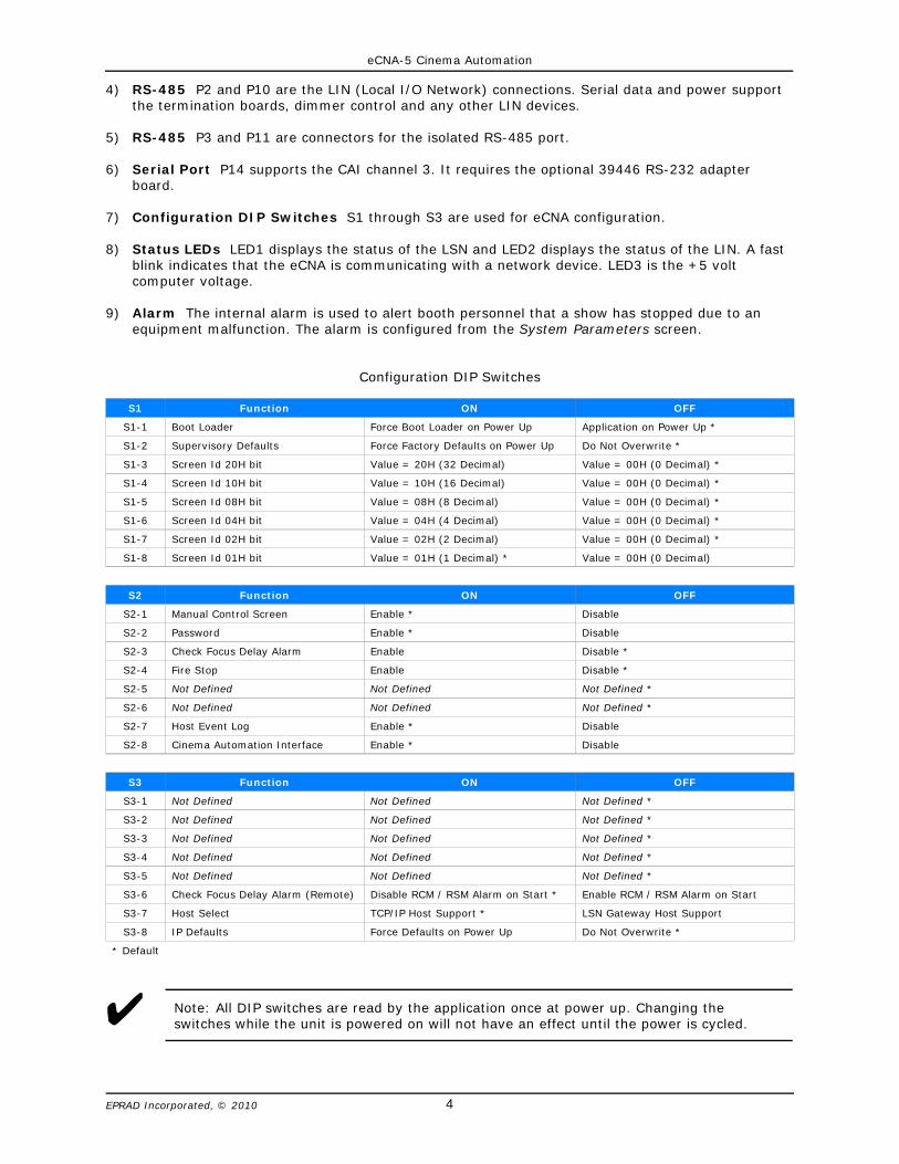
7) Configuration DIP Switches S1 through S3 are used for eCNA configuration.
8) Status LEDs LED1 displays the status of the LSN and LED2 displays the status of the LIN. A fastblink indicates that the eCNA is communicating with a network device. LED3 is the +5 voltcomputer voltage.
9) Alarm The internal alarm is used to alert booth personnel that a show has stopped due to anequipment malfunction. The alarm is configured from the System Parameters screen.
Configuration DIP Switches
S1 Function ON OFF
S1-1 Boot Loader Force Boot Loader on Power Up Application on Power Up *
S1-2 Supervisory Defaults Force Factory Defaults on Power Up Do Not Overwrite *
S1-3 Screen Id 20H bit Value = 20H (32 Decimal) Value = 00H (0 Decimal) *
S1-4 Screen Id 10H bit Value = 10H (16 Decimal) Value = 00H (0 Decimal) *
S1-5 Screen Id 08H bit Value = 08H (8 Decimal) Value = 00H (0 Decimal) *
S1-6 Screen Id 04H bit Value = 04H (4 Decimal) Value = 00H (0 Decimal) *
S1-7 Screen Id 02H bit Value = 02H (2 Decimal) Value = 00H (0 Decimal) *
S1-8 Screen Id 01H bit Value = 01H (1 Decimal) * Value = 00H (0 Decimal)
S2 Function ON OFF
S2-1 Manual Control Screen Enable * Disable
S2-2 Password Enable * Disable
S2-3 Check Focus Delay Alarm Enable Disable *
S2-4 Fire Stop Enable Disable *
S2-5 Not Defined Not Defined Not Defined *
S2-6 Not Defined Not Defined Not Defined *
S2-7 Host Event Log Enable * Disable
S2-8 Cinema Automation Interface Enable * Disable
S3 Function ON OFF
S3-1 Not Defined Not Defined Not Defined *
S3-2 Not Defined Not Defined Not Defined *
S3-3 Not Defined Not Defined Not Defined *
S3-4 Not Defined Not Defined Not Defined *
S3-5 Not Defined Not Defined Not Defined *
S3-6 Check Focus Delay Alarm (Remote) Disable RCM / RSM Alarm on Start * Enable RCM / RSM Alarm on Start
S3-7 Host Select TCP/IP Host Support * LSN Gateway Host Support
S3-8 IP Defaults Force Defaults on Power Up Do Not Overwrite *
* Default
U Note: All DIP switches are read by the application once at power up. Changing theswitches while the unit is powered on will not have an effect until the power is cycled.

eCNA-5 Cinema Automation
5EPRAD Incorporated, © 2010
S1-1 Force Boot Loader on Power Up
The boot loader is a program that supports the firmware download. It is protected and cannot beerased by the user. This ensures that the boot loader can always be reloaded even if the applicationsoftware in flash memory is corrupted due to an incomplete download. If the unit won’t boot due to acorrupted application, setting this switch to ON will force the boot loader to run on a power up. After asuccessful application upgrade, be sure to set this switch back to the OFF position.
S1-2 Supervisory Defaults
When this switch is ON, Supervisory factory defaults will be restored on power up overwriting any userconfiguration.
S1-3 - S1-8 Screen Id
These six switches set the Screen Id number. It is suggested that each unit have these switches set tothe corresponding screen or house number.
S2-1 Manual Control Screen Enable
This switch enables the Output Control and Status screens.

eCNA-5 Cinema Automation
6EPRAD Incorporated, © 2010
S2-2 Local Password Enable
This switch enables the Local password. There is currently no local password protected functions. Thisswitch has no effect.
S2-3 Check Focus Delay Alarm Enable
This switch enables the ‘Check Focus Delay’ function. When this switch is ON the local and RSM/RCMremote station alarm will sound prior to the show starting. This feature alerts the operator that theshow is about to start. The alarm will sound seven seconds before the show starts. This gives theoperator time to make any quick adjustments.
S2-4 Fire Stop Option Enable
This switch enables the Fire Stop option. This only applies to the older 39331 Booth and 39332 Singletermination boards that did not have a dedicated fire stop input. When this switch is ON the remotestop input on these boards was treated as a fire stop.
S2-5 Undefined.
S2-6 Undefined.
S2-7 Event Logging Enable
This switch enables the Event Logging to Host function. When this switch is ON events areautomatically sent to the Host program as they occur. This applies only to the Host port 16000.
S2-8 Cinema Automation Interface (CAI) Enable
This switch enables the three CAI communications channels. When this switch is off, the CAI isDisabled and the eCNA ignores incoming control data.
S3-1 Undefined.
S3-2 Undefined.
S3-3 Undefined.
S3-4 Undefined.
S3-5 Undefined.
S3-6 Defeat Check Focus Delay Alarm at Remote
This switch disables the ‘Check Focus Delay’ alarm at the RSM/RCM remote stations.
S3-7 Ethernet TCP/IP Host Enable
The Host software program can connect to the unit via either the LSN Gateway Interface or EthernetTCP/IP port 16000. This switch selects which communications port the unit will send the unsolicitedstatus data.
S3-8: Ethernet IP Defaults
This switch forces the default Ethernet TCP/IP settings. When this switch is ON, factory defaults will berestored on a power up overwriting the user configured settings.
Ethernet default settings:Duplex: HalfIP Address: 192.168.0.254Subnet Mask: 255.255.255.0Gateway IP: 0.0.0.0
eCNA-5 Cinema Automation
7EPRAD Incorporated, © 2010
3.2 Configuring Ethernet via the Serial Port
The eCNA-5's IP address must be configured before a network connection is available. The Ethernetcommunications can be configured via the RS-232 port, P8, on the Main CPU board. This is a dumbterminal interface and will work with almost any terminal emulation software program running on aPC. A 9 pin D-sub adapter is required to connect the PC to the P8 connector.
RS-232 Communication Parameters
Baud Rate: 19,200 bpsData Length: 8 bitsParity Bit: EvenStop Bits: 1 bitFlow Control: Hardware (RTS-CTS)
The following example uses Windows® HyperTerminal to setup the Ethernet TCP/IP parameters.
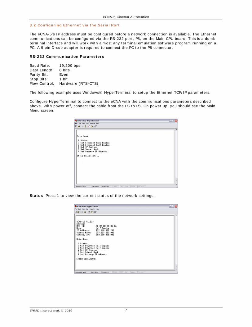
Configure HyperTerminal to connect to the eCNA with the communications parameters describedabove. With power off, connect the cable from the PC to P8. On power up, you should see the MainMenu screen.
Status Press 1 to view the current status of the network settings.

eCNA-5 Cinema Automation
8EPRAD Incorporated, © 2010
Duplex Ethernet communications can operate in Half or Full Duplex mode. This setting will dependon the device that is connected to the eCNA-5 (network switch, PC, etc.). Press 2 to set Ethernet FullDuplex. Press 3 to set Ethernet Half Duplex.
IP Address The IP address assigned to the unit can be modified. Press 4 and enter the new addressin the same format (as the current address) as it appears inside the parenthesis.
Subnet Mask The Subnet Mask assigned to the unit can be modified. Press 5 and enter the newmask in the same format (as the current mask) as it appears inside the parenthesis.

eCNA-5 Cinema Automation
9EPRAD Incorporated, © 2010
Gateway IP Address The Gateway IP Address assigned to the unit can be modified. The Gatewayaddress allows communications to other LAN segments. The gateway address should be the IP addressof the router connected to the same LAN segment as the eCNA. The gateway address must be withinthe local network. Press 6 and enter the new address in the same format (as the current address) as itappears inside the parenthesis.
eCNA-5 Cinema Automation
10EPRAD Incorporated, © 2010
3.3 Configuring via the Web Browser
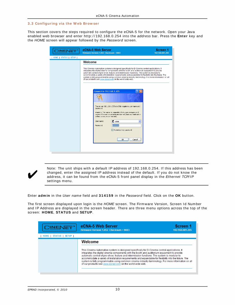
This section covers the steps required to configure the eCNA-5 for the network. Open your Javaenabled web browser and enter http://192.168.0.254 into the address bar. Press the Enter key andthe HOME screen will appear followed by the Password screen.
U
Enter admin in the User name field and 314159 in the Password field. Click on the OK button.
The first screen displayed upon login is the HOME screen. The Firmware Version, Screen Id Numberand IP Address are displayed in the screen header. There are three menu options across the top of thescreen: HOME, STATUS and SETUP.
Note: The unit ships with a default IP address of 192.168.0.254. If this address has beenchanged, enter the assigned IP address instead of the default. If you do not know theaddress, it can be found from the eCNA-5 front panel display in the Ethernet TCP/IPsettings menu.
eCNA-5 Cinema Automation
11EPRAD Incorporated, © 2010
3.3.1 Setup
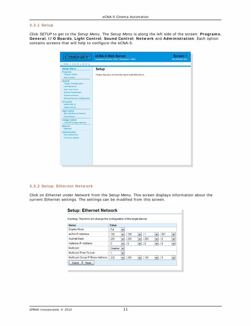
Click SETUP to get to the Setup Menu. The Setup Menu is along the left side of the screen: Programs,General, I/O Boards, Light Control, Sound Control, Network and Administration. Each optioncontains screens that will help to configure the eCNA-5.
3.3.2 Setup: Ethernet Network
Click on Ethernet under Network from the Setup Menu. This screen displays information about thecurrent Ethernet settings. The settings can be modified from this screen.

eCNA-5 Cinema Automation
12EPRAD Incorporated, © 2010
Duplex Mode The Ethernet supports half or full duplex communications. This setting will depend onthe device that is connected to the eCNA-5 (network switch, PC, etc.).
IP Address The IP address assigned to the unit can be modified. Change each octet of the addressby using the list box to select the desired number.
Subnet Mask The Subnet Mask assigned to the unit can be modified. Change each octet of the maskby using the list box to select the desired number.
Gateway IP Address The Gateway IP address assigned to the unit can be modified. Change eachoctet of the address by using the list box to select the desired number.
Multicast IP Multicast allows the eCNAs that belong to the multicast group to exchange status andcontrol information. The network infrastructure between all eCNAs must be multicast capable,including intermediate routers. Multicast can be Enabled or Disabled. Multicast must be enabled andconfigured in order to use the Network Monitor screen.
Multicast Time to Live Each IP Multicast packet uses a time-to-live (TTL) parameter. Thisparameter controls the number of hops that a Multicast packet is allowed to propagate. Each time arouter forwards a packet it’s TTL is decremented. A Multicast packet whose TTL has expired (is 0) isdropped, without an error notification to the sender. This mechanism prevents messages fromneedless transmission to regions of a network that lie beyond the subnets containing the multicastgroup members. This setting will depend on the physical network. You can adjust the range ofmulticast propagations from 0 to 62.
Multicast Group IP Base Address Multicast addresses are in the range from 224.0.0.0 to239.255.255.255. All eCNAs that are to belong to the same multicast group must have the sameMulticast Group IP Starting Address. A block of 30 addresses should be reserved for current and futurecommunications between eCNAs. For example, if you were to assign a starting address of239.255.100.0, be sure that 239.255.100.0 to 239.255.100.30 are not being used for any othermulticast enabled devices. Change each octet of the address by using the list box to select the desirednumber.
IP Multicast Address Ranges and Uses
Range Start Address Range End Address Description
224.0.0.0 224.0.0.255 Reserved for special “well-known” multicast addresses.
224.0.1.0 238.255.255.255 Globally-scoped (internet-wide) multicast addresses.
239.0.0.0 239.255.255.255 Administratively-scoped (local) multicast addresses.
Click on the Reset button to put the original data back. Click the Submit button to save new settingsto the eCNA-5.
U Note: Changes to the Duplex Mode, IP Address, Subnet Mask and Gateway IPAddress will not take effect until the eCNA-5 is re-booted. The eCNA can be re-bootedlocally by cycling power with the front panel power switch or from the web browser byclicking on the Start RTOS button from the Firmware Update screen.

eCNA-5 Cinema Automation
13EPRAD Incorporated, © 2010
3.3.3 Setup: Trigger Configuration
Click on Trigger Configuration under General in the Setup Menu. This screen displays informationabout the trigger assignments.
Triggers are used to initiate macros from internal and external events such as a power up, a fault, akey press or an input.
The following events can be assigned to triggers:
Event Initiated by
Program Abort Abort key or Abort command
Fault Set Fault command, Fault input
Fault Clear Cancel key, Cancel command
Fire Stop Fire Stop input
Idle Transition from In Progress (running a program) to the Idle state
In Progress Start key, Start command
Power Up in Idle eCNA-5 power up (in Idle state)
Resume Start key, Start command
Stop Stop key, Stop command
User-Defined Key 1 - 8 Front panel keys, Browser Status screen Web Keys
In 1 - 16 Input control flags
Timer 1 - 10 General Purpose Timer Expiration
Line Voltage Low Line voltage dropped below Low Voltage Threshold
Line Voltage OK 1 Line voltage restored inside Voltage Low Window
Line Voltage OK 2 Line voltage restored outside Voltage Low Window
eCNA-5 Cinema Automation
14EPRAD Incorporated, © 2010
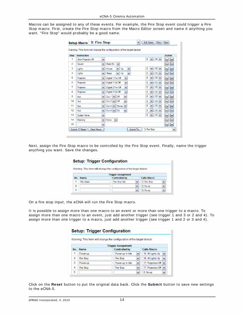
Macros can be assigned to any of these events. For example, the Fire Stop event could trigger a FireStop macro. First, create the Fire Stop macro from the Macro Editor screen and name it anything youwant. “Fire Stop” would probably be a good name.
Next, assign the Fire Stop macro to be controlled by the Fire Stop event. Finally, name the triggeranything you want. Save the changes.
On a fire stop input, the eCNA will run the Fire Stop macro.
It is possible to assign more than one macro to an event or more than one trigger to a macro. Toassign more than one macro to an event, just add another trigger (see trigger 1 and 3 or 2 and 4). Toassign more than one trigger to a macro, just add another trigger (see trigger 1 and 2 or 3 and 4).
Click on the Reset button to put the original data back. Click the Submit button to save new settingsto the eCNA-5.

eCNA-5 Cinema Automation
15EPRAD Incorporated, © 2010
3.3.4 Setup: Fault Behavior
Click on Fault Behavior under General in the Setup Menu. This screen displays information about thebehavior of the output control state flags.
By default, the eCNA-5 memorizes the state of the output control flags when a fault or a stop isreceived and restores the state when a program is resumed or when the fault is cleared in the idlestate. When the eCNA-5 receives a fault from the client, the outputs can be driven to a fault state (seeTrigger Configuration).
When this occurs during a program, the eCNA-5 suspends all active instruction delay timers and savesthe current state of the outputs. When the program is resumed, the timers resume and the outputsare returned to their previous memorized state. When this occurs in the idle state (not running aprogram), the eCNA-5 saves the current state of the outputs. When the fault is cleared, the outputsare returned to their previous memorized state.
This is normally the preferred method of operation. However, if the default operation is not desirable,the Fault Behavior screen allows you to modify this behavior for individual output flags.

eCNA-5 Cinema Automation
16EPRAD Incorporated, © 2010
When to Memorize/Restore the Instruction Timer and Output State:
On Stop or Fault Set/On Resume or Fault Clear - (Default) The state of the output and the timerare memorized on a stop or a fault. The timer resumes and the output is returned to the memorizedstate when the program is resumed or when the fault is cleared in the Idle state.
On Fault Set/On Fault Clear - The state of the output is memorized on a fault. The timer resumesand the output is returned to the memorized state when the fault is cleared.
Never - The timer is not suspended (continues to tick) on a fault or a stop and the output fires whenthe timer expires. In this case the output is not effected unless it is overridden.
Click on the Reset button to put the original data back. Click the Submit button to save new settingsto the eCNA-5.
Output Control Flag Definitions
Digital Projector Power/Video These are the four Digital Projector output control flags, DigitalProj 1 Power, Digital Proj 1 Video, Digital Proj 2 Power and Digital Proj 2 Video. These flagsare controlled with a Program or Macro instruction. The client can also control these flags directly withthe Output (OUT) serial command and can read the status of these flags with the Status (STS),Exchange Status (XST) and Request Status (RST) Commands. These flags can also be sent,unsolicited, to the client in the Report (RPT) Message. If relay control is required, these flags can beassigned to any of the relays on the termination boards.
House Lights These are the house lights Up, Down, Mid 1, and Mid 2 output control flags. Bydefault, these are assigned to the house lights relays. Only one of these flags can be active at a time.These flags are controlled with a Program or Macro instruction. The client can also control these flagsdirectly with the Output (OUT) serial command.
Stage Lights These are the stage lights Up and Down output control flags. By default, these areassigned to the stage lights relays. Only one of these flags can be active at a time. These flags arecontrolled with a Program or Macro instruction. The client can also control these flags directly with theOutput (OUT) serial command.
Curtain These are the Open and Close output control flags. By default, these are assigned to thecurtain relays. Only one of these flags can be active at a time. These flags are controlled with aProgram or Macro instruction. The client can also control these flags directly with the Output (OUT)serial command.
Masking These are the masking Flat, Scope and Special output control flags. By default, these areassigned to the masking relays. Only one of these flags can be active at a time. These flags arecontrolled with a Program or Macro instruction. The client can also control these flags directly with theOutput (OUT) serial command.
Lens These are the lens Flat, Scope and Special output control flags. By default, these are assignedto the lens relays. Only one of these flags can be active at a time. These flags are controlled with aProgram or Macro instruction. The client can also control these flags directly with the Output (OUT)serial command.
Sound These are the sound Non-Sync, Mono, SVA, Digital 1, Aux 1, Digital 2, Aux 2, and Muteoutput control flags. By default, these are assigned to the sound relays. Only one of these flags can beactive at a time. These flags are controlled with a Program or Macro instruction. The client can alsocontrol these flags directly with the Output (OUT) serial command.
Slide Projector This is the Slide (or Auxiliary) Projector output control flag. By default, this isassigned to the slide projector relay. These flags are controlled with a Program or Macro instruction.The client can also control these flags directly with the Output (OUT) serial command and can readthe status of this flag with the Status (STS), Exchange Status (XST) and Request Status (RST)commands.

eCNA-5 Cinema Automation
17EPRAD Incorporated, © 2010
Aux Out 1 - 16 These are the 16 Aux Out output control flags. These flags are controlled with aProgram or Macro instruction. The client can also control these flags directly with the Output (OUT)serial command and can read the status of these flags with the Status (STS), Exchange Status(XST) and Request Status (RST) Commands. If relay control is required, these flags can beassigned to any of the relays on the termination boards.
3.3.5 Setup: Real Time Clock
The eCNA-5 uses an internal clock/calendar to put time and date stamps on logged events. Time anddate is displayed on the local Run Status screen and the Main Status web screen.
Click on Real Time Clock under General from the Setup Menu. This screen is used to setup the internalclock. The time is displayed in 24 hour format. This screen is not automatically refreshed. You mustclick on the Refresh button to get the current the time and date from the eCNA-5. Click on theSubmit button to save your changes to the eCNA-5.
If the eCNA-5 is configured to use network (NTP) time, the Submit button is disabled and the clockcannot be changed. A message is displayed to indicate this condition.
eCNA-5 Cinema Automation
18EPRAD Incorporated, © 2010
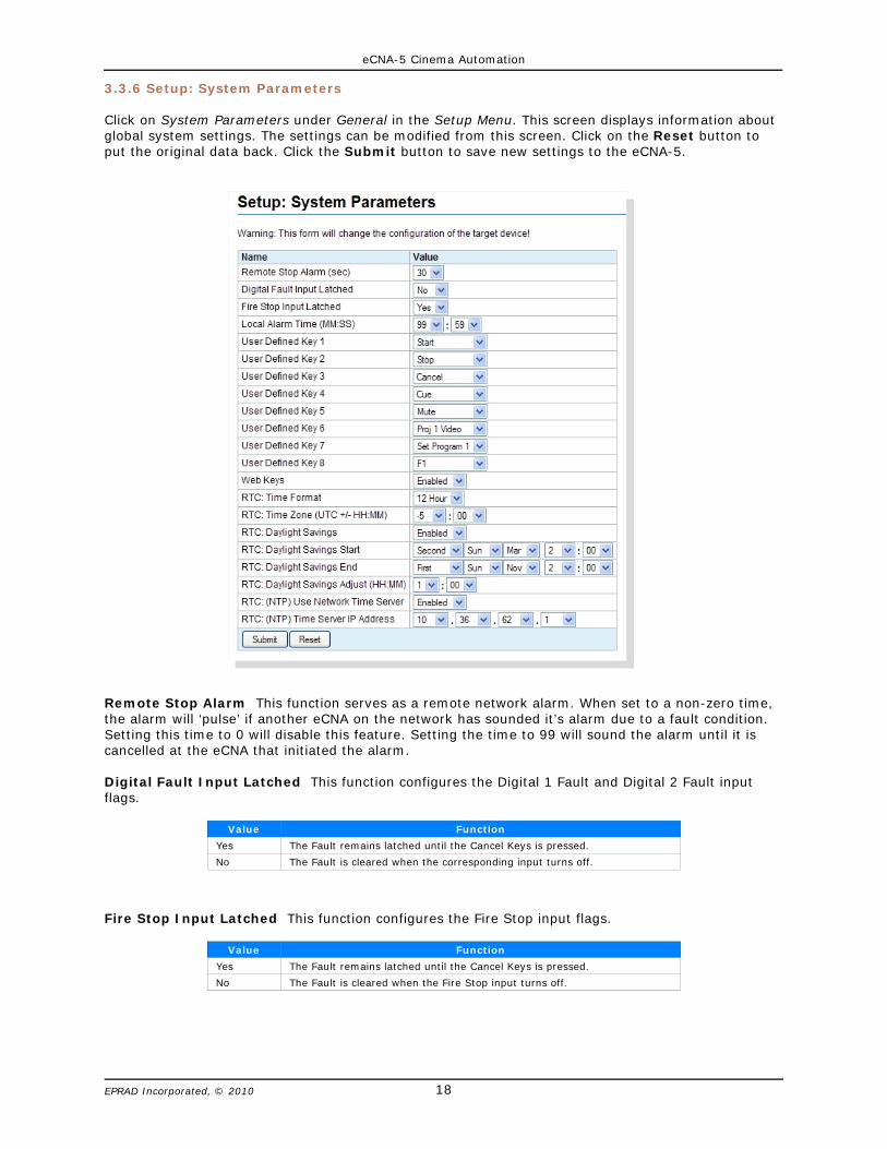
3.3.6 Setup: System Parameters
Click on System Parameters under General in the Setup Menu. This screen displays information aboutglobal system settings. The settings can be modified from this screen. Click on the Reset button toput the original data back. Click the Submit button to save new settings to the eCNA-5.
Remote Stop Alarm This function serves as a remote network alarm. When set to a non-zero time,the alarm will ‘pulse’ if another eCNA on the network has sounded it’s alarm due to a fault condition.Setting this time to 0 will disable this feature. Setting the time to 99 will sound the alarm until it iscancelled at the eCNA that initiated the alarm.
Digital Fault Input Latched This function configures the Digital 1 Fault and Digital 2 Fault inputflags.
Value Function
Yes The Fault remains latched until the Cancel Keys is pressed.
No The Fault is cleared when the corresponding input turns off.
Fire Stop Input Latched This function configures the Fire Stop input flags.
Value Function
Yes The Fault remains latched until the Cancel Keys is pressed.
No The Fault is cleared when the Fire Stop input turns off.

eCNA-5 Cinema Automation
19EPRAD Incorporated, © 2010
Local Alarm Time (MM:SS) This function configures the local alarm.
Time (mm:ss) Function
00:00 Disables the local alarm.
99:59 Alarm will sound until cancelled
00:01 to 99:58 Alarm will sound until time expires or cancelled.
User Defined Keys This allows the user to customize the front panel controls. The eight front panelkeys can be assigned to any of the functions in the table below.
Key Function
<<blank>> Key has no function.
Start Starts or Resumes a program.
Stop Stops a Program. Press and hold for 5 seconds to abort a program.
Cue Forces a cue event.
Cancel Cancels the alarm or clears any ‘latched’ faults.
Bypass Not used.
Volume Up Ramps volume up.
Volume Down Ramps volume down.
Mute Mutes the sound.
Proj 1 Video Toggles Projector 1 Video output.
Proj 1 Power Toggles Projector 1 Power output.
Proj 2 Video Toggles Projector 2 Video output.
Proj 2 Power Toggles Projector 2 Power output.
Set Program 1 Sets the program to 1.
Set Program 2 Sets the program to 2.
Set Program 3 Sets the program to 3.
Set Program 4 Sets the program to 4.
Set Program 5 Sets the program to 5.
Set Program 6 Sets the program to 6.
Set Program 7 Sets the program to 7.
Set Program 8 Sets the program to 8.
Set Program 9 Sets the program to 9.
F1 F1 key will be displayed on the Main Status screen if Web Keys are enabled.
F2 F2 key will be displayed on the Main Status screen if Web Keys are enabled.
F3 F3 key will be displayed on the Main Status screen if Web Keys are enabled.
F4 F4 key will be displayed on the Main Status screen if Web Keys are enabled.
F5 F5 key will be displayed on the Main Status screen if Web Keys are enabled.
F6 F6 key will be displayed on the Main Status screen if Web Keys are enabled.
F7 F7 key will be displayed on the Main Status screen if Web Keys are enabled.
F8 F8 key will be displayed on the Main Status screen if Web Keys are enabled.
Program Abort Aborts a program (back to idle state). Outputs are not changed.
Pause Pauses a Program.
Web Keys This Enables or Disables the manual control buttons on the Main Status web screen. Thebutton functions are the same as the User Defined front panel keys.
RTC: Time Format The clock can be set to display 12 or 24 hours time. Use the list box to changethe time to 12 hour or 24 hour format.

eCNA-5 Cinema Automation
20EPRAD Incorporated, © 2010
RTC: Time Zone (UTC +/- HH:MM) When the eCNA-5 is configured to synchronize it’s clock to anNTP Server, an offset time needs to be applied to the Coordinated Universal Time (UTC). For example,if you are in the Eastern Standard Time zone, set the value to -5:00.
Standard Time Zones in North America and Hawaii
Abbreviation Full Name Time Zone
NST Newfoundland Standard Time UTC - 3:30 hours
AST Atlantic Standard Time UTC - 4 hours
EST Eastern Standard Time UTC - 5 hours
CST Central Standard Time UTC - 6 hours
MST Mountain Standard Time UTC - 7 hours
PST Pacific Standard Time UTC - 8 hours
AKST Alaska Standard Time UTC - 9 hours
HAST Hawaii-Aleutian Standard Time UTC - 10 hours
RTC: Daylight Savings This applies the Daylight time adjustment to the clock. Select Enabled toautomatically adjust for daylight savings.
RTC: Daylight Savings Start/RTC: Daylight Savings End If the Daylight Savings is Enabled, thedaylight savings start and end time must be configured for your location.
Daylight Savings Time Rules
Location DST Begins DST Ends
North America 2 a.m. on the second Sunday in March 2 a.m. on the first Sunday in November
European Union 1 a.m. on the last Sunday in March 1 a.m. on the last Sunday in October
Australia 2 a.m. on the first Sunday in October 3 a.m. on the first Sunday in April
New Zealand 2 a.m. on the last Sunday in September 3 a.m. on the first Sunday in April
RTC: Daylight Savings Adjust (HH:MM) The DST adjustment time is in hours and minutes. This isthe amount of time that the time will move forward at the beginning of DST and backward at the endof DST.
RTC: (NTP) Use Network Time Server The Network Time Protocol (N.T.P.) is an Ethernet TCP/IPprotocol for distributing the universal time (U.C.) for the purpose of synchronizing the clocks ofcomputer systems. The eCNA-5 implements SNTP and can be setup to be an NTP client. In order touse the NTP, a Network Time Server on the LAN or WAN must be available. Normally, a dedicatedtime server is installed inside the firewall of the LAN. Select Enabled to use the Network Time Server.
U Note: If the time server is on the other side of a router that is connected to the networksubnet that the eCNA-5 belongs, remember to assign the router’s IP address to theGateway IP Address from the Ethernet Network setup screen.
eCNA-5 Cinema Automation
21EPRAD Incorporated, © 2010
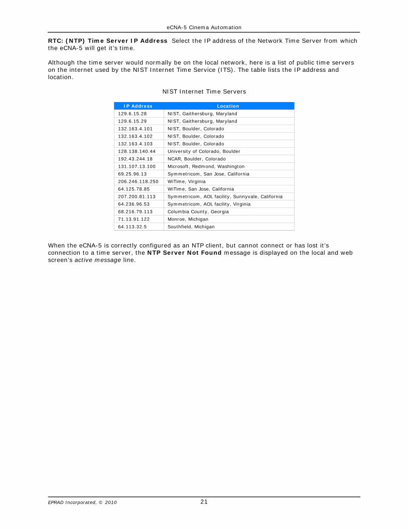
RTC: (NTP) Time Server IP Address Select the IP address of the Network Time Server from whichthe eCNA-5 will get it’s time.
Although the time server would normally be on the local network, here is a list of public time serverson the internet used by the NIST Internet Time Service (ITS). The table lists the IP address andlocation.
NIST Internet Time Servers
IP Address Location
129.6.15.28 NIST, Gaithersburg, Maryland
129.6.15.29 NIST, Gaithersburg, Maryland
132.163.4.101 NIST, Boulder, Colorado
132.163.4.102 NIST, Boulder, Colorado
132.163.4.103 NIST, Boulder, Colorado
128.138.140.44 University of Colorado, Boulder
192.43.244.18 NCAR, Boulder, Colorado
131.107.13.100 Microsoft, Redmond, Washington
69.25.96.13 Symmetricom, San Jose, California
206.246.118.250 WiTime, Virginia
64.125.78.85 WiTime, San Jose, California
207.200.81.113 Symmetricom, AOL facility, Sunnyvale, California
64.236.96.53 Symmetricom, AOL facility, Virginia
68.216.79.113 Columbia County, Georgia
71.13.91.122 Monroe, Michigan
64.113.32.5 Southfield, Michigan
When the eCNA-5 is correctly configured as an NTP client, but cannot connect or has lost it’sconnection to a time server, the NTP Server Not Found message is displayed on the local and webscreen’s active message line.
eCNA-5 Cinema Automation
22EPRAD Incorporated, © 2010
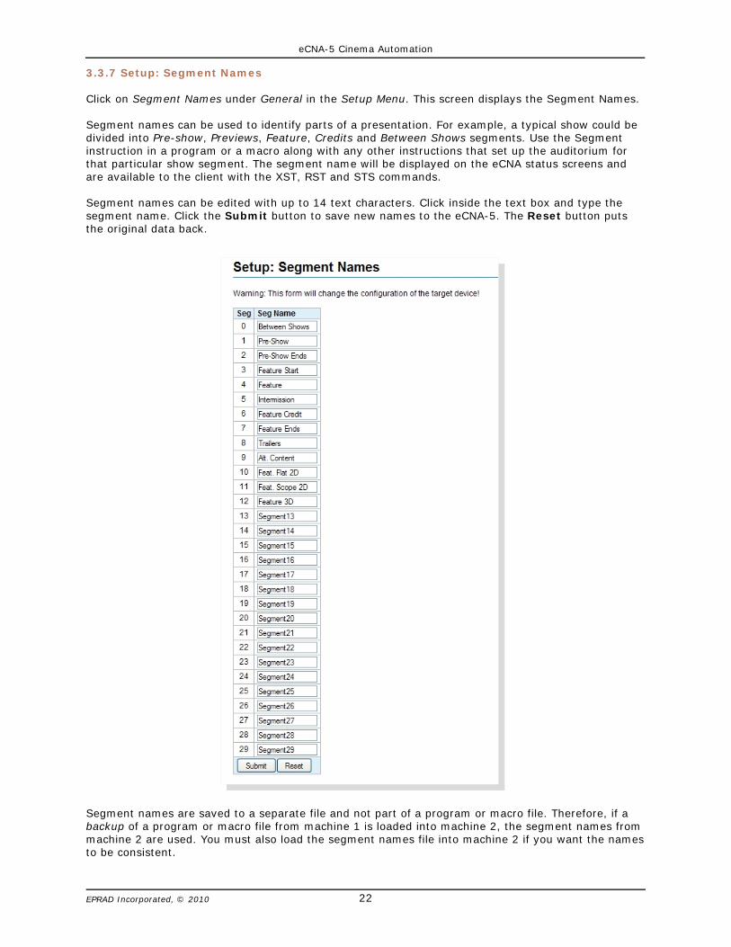
3.3.7 Setup: Segment Names
Click on Segment Names under General in the Setup Menu. This screen displays the Segment Names.
Segment names can be used to identify parts of a presentation. For example, a typical show could bedivided into Pre-show, Previews, Feature, Credits and Between Shows segments. Use the Segmentinstruction in a program or a macro along with any other instructions that set up the auditorium forthat particular show segment. The segment name will be displayed on the eCNA status screens andare available to the client with the XST, RST and STS commands.
Segment names can be edited with up to 14 text characters. Click inside the text box and type thesegment name. Click the Submit button to save new names to the eCNA-5. The Reset button putsthe original data back.
Segment names are saved to a separate file and not part of a program or macro file. Therefore, if abackup of a program or macro file from machine 1 is loaded into machine 2, the segment names frommachine 2 are used. You must also load the segment names file into machine 2 if you want the namesto be consistent.

eCNA-5 Cinema Automation
23EPRAD Incorporated, © 2010
3.3.8 Setup: Remote Device Configuration
Click on Remote Device Configuration under General in the Setup Menu. This screen is used to setupcommunications parameters and command messages.
The eCNA-5 supports five TCP client communication channels. These are used to connect to a remotedevice such as a projector, sound processor, etc.
Device This is a list of supported devices including Raw. Select the device that the eCNA-5 will becontrolling.
Device Name Enter the Device Name (up to 10 characters). This name is used in the eCNA-5 macroand program instruction.
IP Address Enter the IP address of the remote device. See remote device documentation.
Port Number Enter the port number of the remote device. See remote device documentation.
Enable Select Enable to enable communications to the remote device.

eCNA-5 Cinema Automation
24EPRAD Incorporated, © 2010
Enter the Message Name of the command here (up to 14 characters). This name is used in the newmacro instruction.
The Message Command Code is the actual command sent to the remote device. These are thecommands supported by a particular device. Remote Device configuration files are available fromEPRAD for supported devices.
The Resp checkbox tells the eCNA whether or not to expect a response from the Remote Device.Some devices send an acknowledgment to the command, so this box must be ‘checked’ if the devicesends a response.
Click Submit to save configuration to the eCNA. Click Reset to abort any changes.
The Prev and Next buttons take you to another device setup screen.
Note: Message Command codes can be added, removed or edited as required. They can be enteredin both binary and ASCII. Enter binary data using hex numbers. ASCII characters must be insidethe curly braces { }. It is okay to put spaces between data bytes for clarity. For supported devices,it is only necessary to enter the command itself. Any start byte, Id, checksum, etc. areautomatically inserted. The maximum length of a command code is 40 characters. For Raw devicecommands, you must enter the entire command including a checksum if required.
Only use commands that force an action at the device (such as turning the lamp on). Statuscommands that request information from the device serve no purpose here. Status requestssupported devices will be handled by the eCNA automatically.
Remember these are the actual command codes sent to the device, so be sure to enter themcorrectly. Contact EPRAD or the device vendor for support.
eCNA-5 Cinema Automation
25EPRAD Incorporated, © 2010
3.3.9 I/O Boards
The eCNA-5 is normally used with the House/Aux termination board to provide digital inputs andoutputs. This board is available in two form factors, the 39431 and the 39445. An optional auxiliaryI/O board (39436) can plug onto either of these boards to provide an additional eight I/O points.
By default, the relays are internally mapped to their corresponding control flags. For example theHouse Lights Up Relay is controlled by the House Lights Up control flag. However, relay control can bere-assigned to any output control flag. For example, the Slide Projector relay can be controlled by theSound Non-Sync control flag.
Outputs are controlled by Program/Macro Instructions and Serial Commands and can be overridden bymanual control. The relays can be configured for Pulsed or Maintained. The pulse duration is abouttwo seconds.
Most inputs can also be reconfigured. For example, the Stop input could be re-assigned to the Pauseinput control flag. Most inputs only require a momentary pulse in order to set the input control flag.The duration of an input pulse should be at least 0.5 seconds.
The eCNA-5 also supports termination boards not described in this manual. These include thefollowing:
• 39490 GPIO Board• 39432-1 Combo I/O Board• 39432-2 Film I/O Board• 39330 Console I/O Board (legacy)• 39331 Booth I/O Board (legacy)• 39332 Single I/O Board (legacy)
eCNA-5 Cinema Automation
26EPRAD Incorporated, © 2010
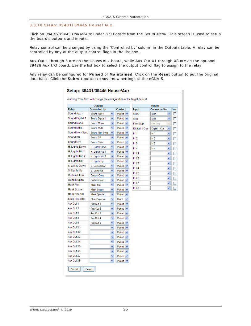
3.3.10 Setup: 39431/39445 House/Aux
Click on 39431/39445 House/Aux under I/O Boards from the Setup Menu. This screen is used to setupthe board’s outputs and inputs.
Relay control can be changed by using the ‘Controlled by’ column in the Outputs table. A relay can becontrolled by any of the output control flags in the list box.
Aux Out 1 through 5 are on the House/Aux board, while Aux Out X1 through X8 are on the optional39436 Aux I/O board. Use the list box to select the output control flag to assign to the relay.
Any relay can be configured for Pulsed or Maintained. Click on the Reset button to put the originaldata back. Click the Submit button to save new settings to the eCNA-5.
eCNA-5 Cinema Automation
27EPRAD Incorporated, © 2010
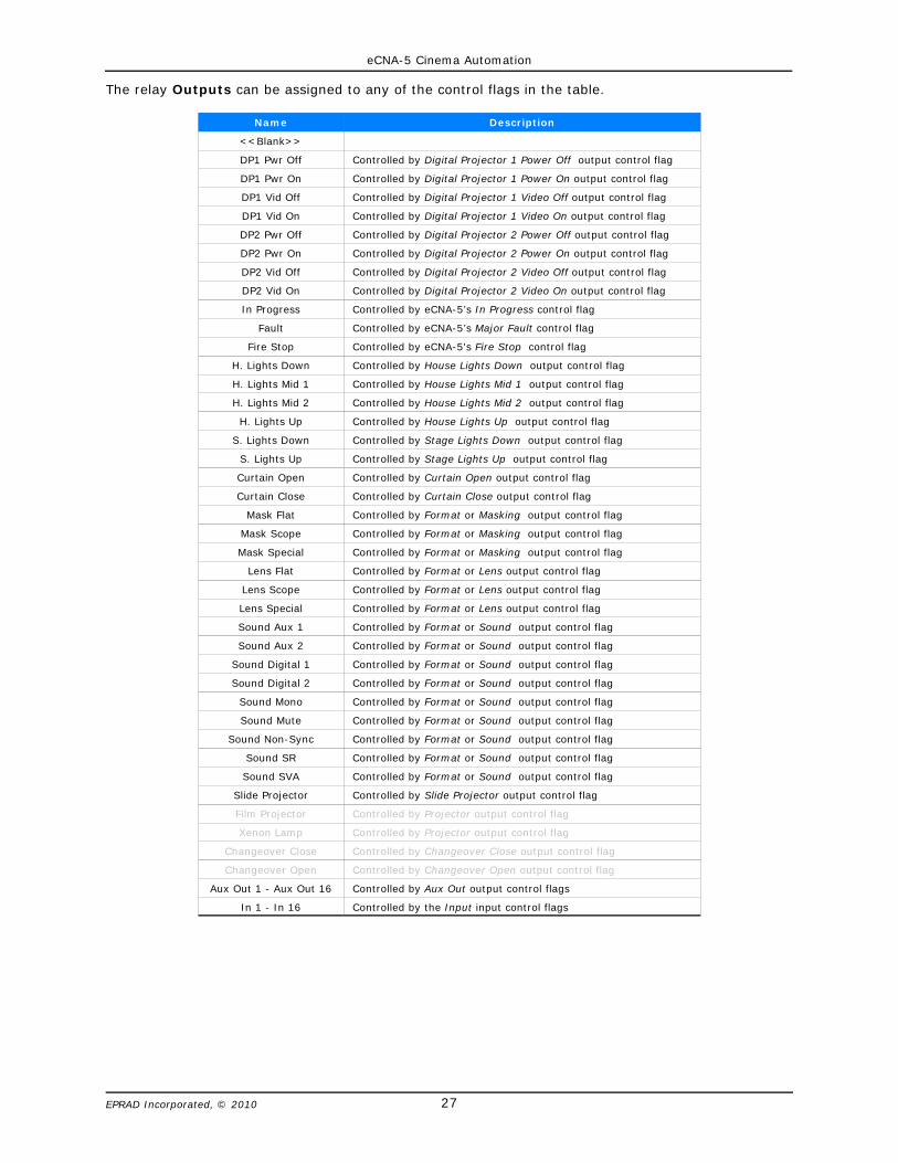
The relay Outputs can be assigned to any of the control flags in the table.
Name Description
<<Blank>>
DP1 Pwr Off Controlled by Digital Projector 1 Power Off output control flag
DP1 Pwr On Controlled by Digital Projector 1 Power On output control flag
DP1 Vid Off Controlled by Digital Projector 1 Video Off output control flag
DP1 Vid On Controlled by Digital Projector 1 Video On output control flag
DP2 Pwr Off Controlled by Digital Projector 2 Power Off output control flag
DP2 Pwr On Controlled by Digital Projector 2 Power On output control flag
DP2 Vid Off Controlled by Digital Projector 2 Video Off output control flag
DP2 Vid On Controlled by Digital Projector 2 Video On output control flag
In Progress Controlled by eCNA-5’s In Progress control flag
Fault Controlled by eCNA-5’s Major Fault control flag
Fire Stop Controlled by eCNA-5's Fire Stop control flag
H. Lights Down Controlled by House Lights Down output control flag
H. Lights Mid 1 Controlled by House Lights Mid 1 output control flag
H. Lights Mid 2 Controlled by House Lights Mid 2 output control flag
H. Lights Up Controlled by House Lights Up output control flag
S. Lights Down Controlled by Stage Lights Down output control flag
S. Lights Up Controlled by Stage Lights Up output control flag
Curtain Open Controlled by Curtain Open output control flag
Curtain Close Controlled by Curtain Close output control flag
Mask Flat Controlled by Format or Masking output control flag
Mask Scope Controlled by Format or Masking output control flag
Mask Special Controlled by Format or Masking output control flag
Lens Flat Controlled by Format or Lens output control flag
Lens Scope Controlled by Format or Lens output control flag
Lens Special Controlled by Format or Lens output control flag
Sound Aux 1 Controlled by Format or Sound output control flag
Sound Aux 2 Controlled by Format or Sound output control flag
Sound Digital 1 Controlled by Format or Sound output control flag
Sound Digital 2 Controlled by Format or Sound output control flag
Sound Mono Controlled by Format or Sound output control flag
Sound Mute Controlled by Format or Sound output control flag
Sound Non-Sync Controlled by Format or Sound output control flag
Sound SR Controlled by Format or Sound output control flag
Sound SVA Controlled by Format or Sound output control flag
Slide Projector Controlled by Slide Projector output control flag
Film Projector Controlled by Projector output control flag
Xenon Lamp Controlled by Projector output control flag
Changeover Close Controlled by Changeover Close output control flag
Changeover Open Controlled by Changeover Open output control flag
Aux Out 1 - Aux Out 16 Controlled by Aux Out output control flags
In 1 - In 16 Controlled by the Input input control flags
eCNA-5 Cinema Automation
28EPRAD Incorporated, © 2010
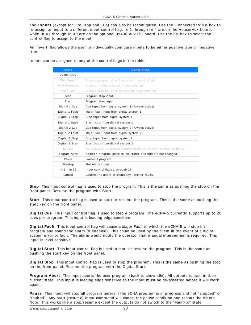
The Inputs (except for Fire Stop and Cue) can also be reconfigured. Use the ‘Connected to’ list box tore-assign an input to a different input control flag. In 1 through In 4 are on the House/Aux board,while In X1 through In X8 are on the optional 39436 Aux I/O board. Use the list box to select thecontrol flag to assign to the input.
An ‘invert’ flag allows the user to individually configure inputs to be either positive true or negativetrue.
Inputs can be assigned to any of the control flags in the table.
Name Description
<<Blank>>
Film Motion Stops a program after 2 seconds if not satisfied.
Film Presence Stops or prevents a start if not satisfied.
Xenon Fault Stops a program after 10 seconds if not satisfied.
Stop Program stop input
Start Program start input
Digital 1 Cue Cue Input from digital system 1 (Always active)
Digital 1 Fault Major Fault input from digital system 1
Digital 1 Stop Stop Input from digital system 1
Digital 1 Start Start Input from digital system 1
Digital 2 Cue Cue Input from digital system 2 (Always active)
Digital 2 Fault Major Fault input from digital system 2
Digital 2 Stop Stop Input from digital system 2
Digital 2 Start Start Input from digital system 2
Bypass De-activates the Bypass Control Relays on 39440 Termination Board.
Program Abort Aborts a program (back to idle state). Outputs are not changed.
Pause Pauses a program.
Firestop Fire Alarm Input
In 1 - In 16 Input control flags 1 through 16.
Cancel Cancels the alarm or clears any ‘latched’ faults.
Stop This input control flag is used to stop the program. This is the same as pushing the stop on thefront panel. Resume the program with Start.
Start This input control flag is used to start or resume the program. This is the same as pushing thestart key on the front panel.
Digital Cue This input control flag is used to step a program. The eCNA-5 currently supports up to 20cues per program. This input is leading edge sensitive.
Digital Fault This input control flag will cause a Major Fault in which the eCNA-5 will stop it’sprogram and sound the alarm (if enabled). This could be used by the client in the event of a digitalsystem error or fault. The alarm would notify the operator that manual intervention is required. Thisinput is level sensitive.
Digital Start This input control flag is used to start or resume the program. This is the same aspushing the start key on the front panel.
Digital Stop This input control flag is used to stop the program. This is the same as pushing the stopon the front panel. Resume the program with the Digital Start.
Program Abort This input aborts the user program (back to show idle). All outputs remain in theircurrent state. This input is leading edge sensitive so the input must be de-asserted before it will workagain.
Pause This input will stop all program timers if the eCNA program is in progress and not “stopped” or“faulted”. Any start (resume) input command will cancel the pause condition and restart the timers.Note: This works like a stop/resume except the outputs do not switch to the “Fault-to” state.

eCNA-5 Cinema Automation
29EPRAD Incorporated, © 2010
Firestop This input control flag causes the firestop event which can be assigned to a trigger to initiatea fire alarm macro.
In1 - In16 The inputs can be connected to input control flags. These control flags can be used toactivate Triggers or can be connected directly to relay outputs.
For example, input IN 1 can be configured to control the Slide Projector relay. Configure IN 1 to beconnected to the In 1 control flag and configure the Slide Projector relay to be controlled by the In 1control flag.
Click on the Reset button to put the original data back. Click the Submit button to save new settingsto the eCNA-5.
Cancel This input control flag cancels the alarm or clears any ‘latched’ faults.
Invert Flag
The inputs can be individually configured for positive true or negative true. Click on the Inv check boxnext to the input you want to invert.

eCNA-5 Cinema Automation
30EPRAD Incorporated, © 2010
3.3.11 Setup: Light Control
The eCNA-5 software supports up to four QDC-400 4-channel dimmer control boards for a total ofsixteen channels. If the QDC-400 is installed on the LIN use the following two screens to set up theQDC-400.
U
3.3.12 Setup: Zone Names
Click on Zone Names under Light Control in the Setup Menu. Up to sixteen different light zones aresupported by the QDC dimmer. Each zone name can be can be named to indicate it’s particularfunction. Zone 1 is fixed for House lights and Zone 2 is fixed for Stage lights. Zones 3 through 16can be named with up to eight characters of text. Click in the Zone Name text box and enter the zonename. These names are used in the QDC-400 Dimmer Boards setup screen and the Lights instruction.
Click on the Reset button to put the original data back. Click the Submit button to save new settingsto the eCNA-5.
Note: This board is powered by the Local I/O Network (LIN). If more than one QDC-400dimmer control board is to be installed on the LIN, make sure the eCNA-5's power supply isof sufficient size. See Power Supply section.
eCNA-5 Cinema Automation
31EPRAD Incorporated, © 2010
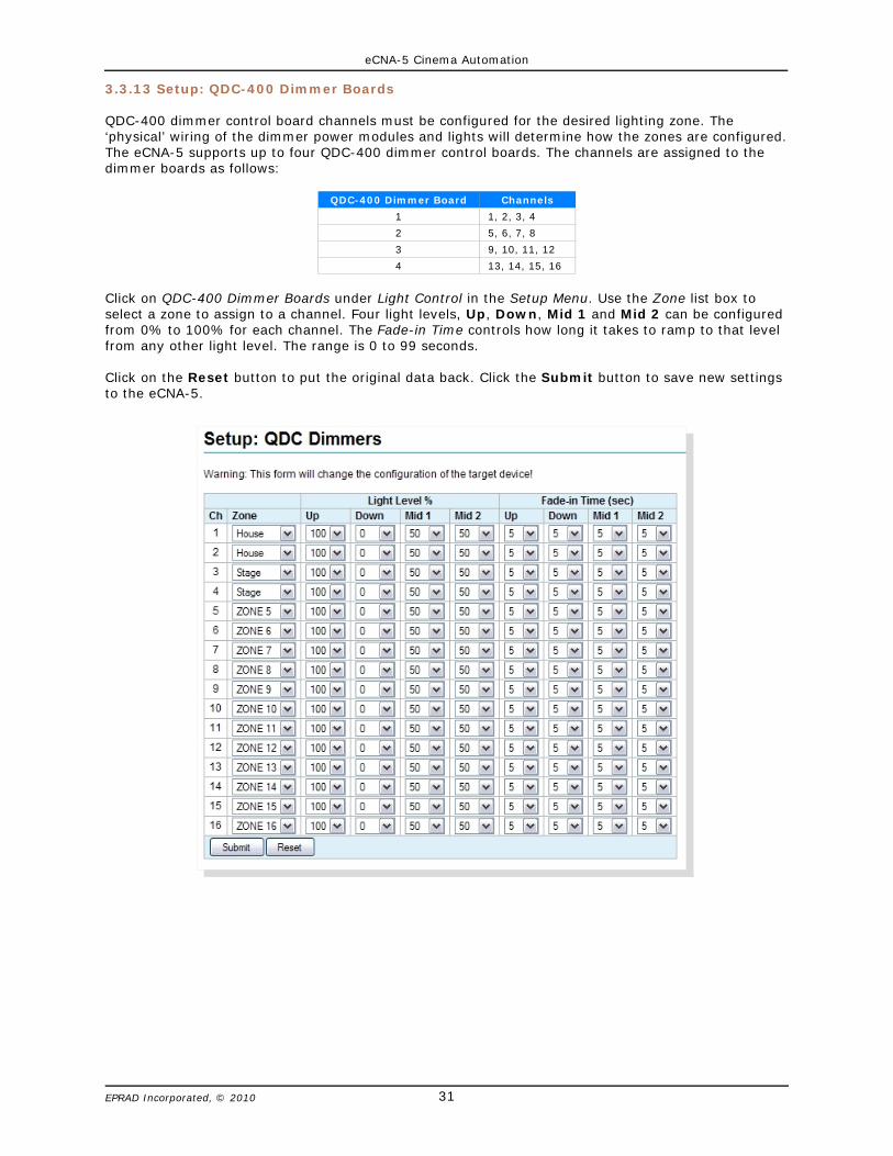
3.3.13 Setup: QDC-400 Dimmer Boards
QDC-400 dimmer control board channels must be configured for the desired lighting zone. The‘physical’ wiring of the dimmer power modules and lights will determine how the zones are configured.The eCNA-5 supports up to four QDC-400 dimmer control boards. The channels are assigned to thedimmer boards as follows:
QDC-400 Dimmer Board Channels
1 1, 2, 3, 4
2 5, 6, 7, 8
3 9, 10, 11, 12
4 13, 14, 15, 16
Click on QDC-400 Dimmer Boards under Light Control in the Setup Menu. Use the Zone list box toselect a zone to assign to a channel. Four light levels, Up, Down, Mid 1 and Mid 2 can be configuredfrom 0% to 100% for each channel. The Fade-in Time controls how long it takes to ramp to that levelfrom any other light level. The range is 0 to 99 seconds.
Click on the Reset button to put the original data back. Click the Submit button to save new settingsto the eCNA-5.

eCNA-5 Cinema Automation
32EPRAD Incorporated, © 2010
3.3.14 Setup: RVC-5 Card
Click on RVC-5 Volume Card under Sound Control in the Setup Menu. Use this screen to configure theeCNA-5 for the optional RVC-5 Remote Volume Control card. The RVC-5's analog output connects tothe remote fader input of the sound processor. This card is available as a single or dual version. TheRVC-5S has one isolated fader control output. The RVC-5D has two isolated fader control outputs.Select Enabled to use the card. Configure Output 1 and/or Output 2 for the type of sound processorused. Control the volume level manually from the eCNA-5 front panel or automatically by using theVolume program instruction.
Sound Processors Supported
Dolby CP65
Dolby CP500
Ultra Stereo JS-20
EPRAD DSS
Sony DFP-D3000
UClick on the Reset button to put the original data back. Click the Submit button to save new settingsto the eCNA-5.
Note: Although the fader control output was designed to specifically match these particularsound processor remote fader inputs, the RVC-5 may work with other models as well.
eCNA-5 Cinema Automation
33EPRAD Incorporated, © 2010
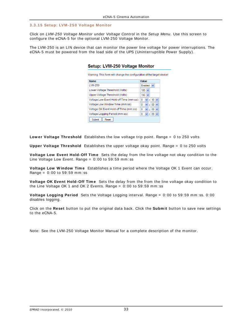
3.3.15 Setup: LVM-250 Voltage Monitor
Click on LVM-250 Voltage Monitor under Voltage Control in the Setup Menu. Use this screen toconfigure the eCNA-5 for the optional LVM-250 Voltage Monitor.
The LVM-250 is an LIN device that can monitor the power line voltage for power interruptions. TheeCNA-5 must be powered from the load side of the UPS (Uninterruptible Power Supply).
Lower Voltage Threshold Establishes the low voltage trip point. Range = 0 to 250 volts
Upper Voltage Threshold Establishes the upper voltage okay point. Range = 0 to 250 volts
Voltage Low Event Hold-Off Time Sets the delay from the line voltage not okay condition to theLine Voltage Low Event. Range = 0:00 to 59:59 mm:ss
Voltage Low Window Time Establishes a time period where the Voltage OK 1 Event can occur.Range = 0:00 to 59:59 mm:ss
Voltage OK Event Hold-Off Time Sets the delay from the from the line voltage okay condition tothe Line Voltage OK 1 and OK 2 Events. Range = 0:00 to 59:59 mm:ss
Voltage Logging Period Sets the Voltage Logging interval. Range = 0:00 to 59:59 mm:ss. 0:00disables logging.
Click on the Reset button to put the original data back. Click the Submit button to save new settingsto the eCNA-5.
Note: See the LVM-250 Voltage Monitor Manual for a complete description of the monitor.
eCNA-5 Cinema Automation
34EPRAD Incorporated, © 2010
3.3.16 Administration
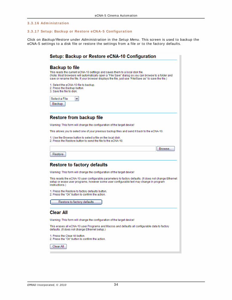
3.3.17 Setup: Backup or Restore eCNA-5 Configuration
Click on Backup/Restore under Administration in the Setup Menu. This screen is used to backup theeCNA-5 settings to a disk file or restore the settings from a file or to the factory defaults.
eCNA-5 Cinema Automation
35EPRAD Incorporated, © 2010
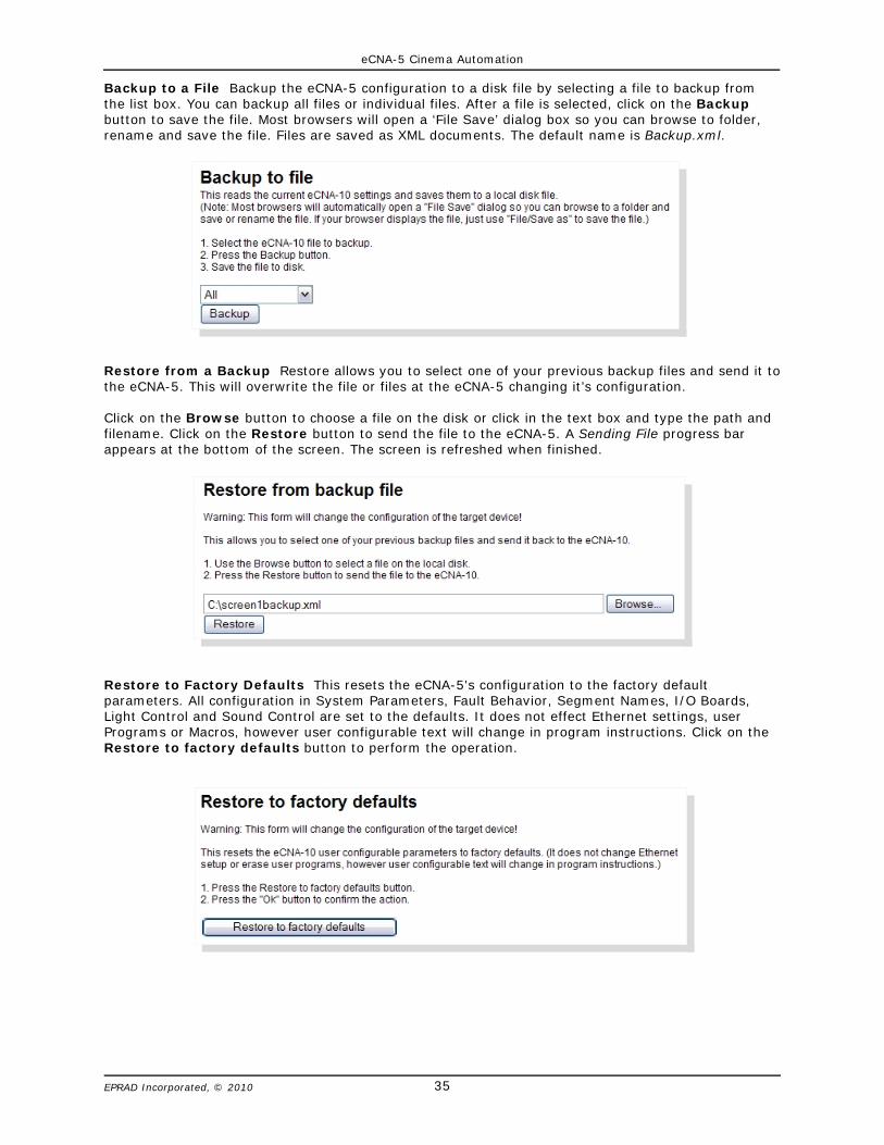
Backup to a File Backup the eCNA-5 configuration to a disk file by selecting a file to backup fromthe list box. You can backup all files or individual files. After a file is selected, click on the Backupbutton to save the file. Most browsers will open a ‘File Save’ dialog box so you can browse to folder,rename and save the file. Files are saved as XML documents. The default name is Backup.xml.
Restore from a Backup Restore allows you to select one of your previous backup files and send it tothe eCNA-5. This will overwrite the file or files at the eCNA-5 changing it’s configuration.
Click on the Browse button to choose a file on the disk or click in the text box and type the path andfilename. Click on the Restore button to send the file to the eCNA-5. A Sending File progress barappears at the bottom of the screen. The screen is refreshed when finished.
Restore to Factory Defaults This resets the eCNA-5's configuration to the factory defaultparameters. All configuration in System Parameters, Fault Behavior, Segment Names, I/O Boards,Light Control and Sound Control are set to the defaults. It does not effect Ethernet settings, userPrograms or Macros, however user configurable text will change in program instructions. Click on theRestore to factory defaults button to perform the operation.

eCNA-5 Cinema Automation
36EPRAD Incorporated, © 2010
Clear All This resets the eCNA-5's configuration to the factory default parameters. All configuration inSystem Parameters, Fault Behavior, Segment Names, I/O Boards, Light Control, Sound Control,Macros and Programs are set to the defaults. It does not effect Ethernet settings. Click on the ClearAll button to perform the operation.

eCNA-5 Cinema Automation
37EPRAD Incorporated, © 2010
3.3.18 Setup: Device Firmware Update
Click on Firmware Update under Administration in the Setup Menu. This screen is used to upgrade theeCNA-5 application firmware. The screen shows status of the current application and boot loaderprograms. The screen is not automatically updated.
U
Before proceeding with the upgrade, the following is recommended:
a) Backup the eCNA-5 configuration files. b) Make note of the version and checksum of the firmware currently installed.c) Make sure the software to be installed is compatible with the eCNA-5.d) Have the installation file of the software currently installed available.
The Start Boot button starts the boot loader program. The Start RTOS button just re-starts theapplication without making any changes to the eCNA-5.
Note: The firmware cannot be updated if the application is running a program. This isindicated by the App Busy flag. If a program is running, end or abort the program andclick on the Refresh Table button to update the screen. The Start Boot and Start RTOSbuttons should now be enabled.
eCNA-5 Cinema Automation
38EPRAD Incorporated, © 2010
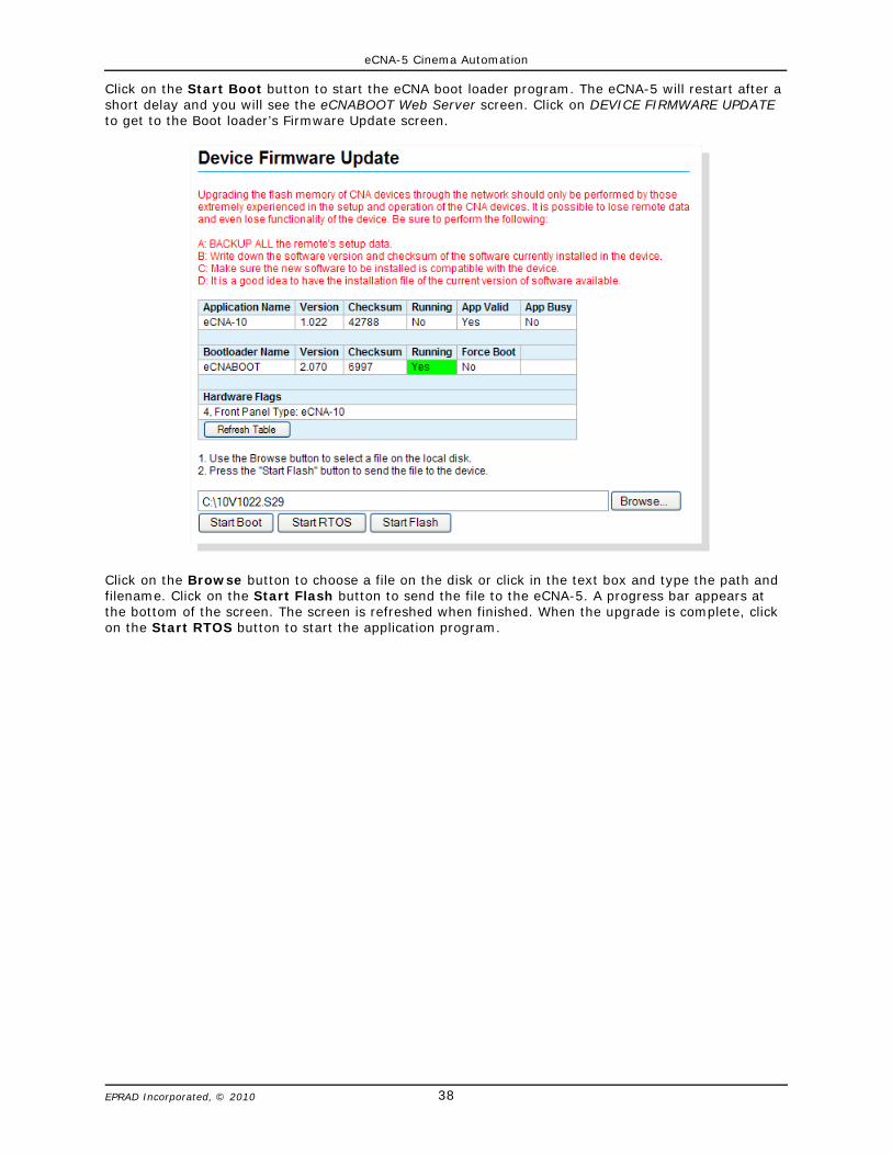
Click on the Start Boot button to start the eCNA boot loader program. The eCNA-5 will restart after ashort delay and you will see the eCNABOOT Web Server screen. Click on DEVICE FIRMWARE UPDATEto get to the Boot loader’s Firmware Update screen.
Click on the Browse button to choose a file on the disk or click in the text box and type the path andfilename. Click on the Start Flash button to send the file to the eCNA-5. A progress bar appears atthe bottom of the screen. The screen is refreshed when finished. When the upgrade is complete, clickon the Start RTOS button to start the application program.
eCNA-5 Cinema Automation
39EPRAD Incorporated, © 2010
3.3.19 Programs
A program is a series of instructions that are executed as they are encountered. The Wait Cueinstruction is a special instruction that causes the program to wait for a cue event before continuing.Many instructions have an associated offset time which allow time-delayed execution. The eCNA-5 canstore up to nine programs. A macro is similar to a program but is used differently. The eCNA-5 canstore up to thirty macros.
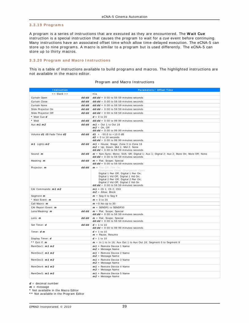
3.3.20 Program and Macro Instructions
This is a table of instructions available to build programs and macros. The highlighted instructions arenot available in the macro editor.
Program and Macro Instructions
Instruction Parameters / Offset Time
<< blank >> n/a
Curtain Open dd:dd dd:dd = 0:00 to 59:59 minutes:seconds
Curtain Close dd:dd dd:dd = 0:00 to 59:59 minutes:seconds
Curtain None dd:dd dd:dd = 0:00 to 59:59 minutes:seconds
Slide Projector On dd:dd dd:dd = 0:00 to 59:59 minutes:seconds
Slide Projector Off dd:dd dd:dd = 0:00 to 59:59 minutes:seconds
* Wait Cue d d = 0 to 20
* Wait dd:dd dd:dd = 0:00 to 99:99 minutes:seconds
Aux m1 m2 dd:dd m1 = Out 1 to Out 16m2 = On, Offdd:dd = 0:00 to 99:99 minutes:seconds
Volume d1 dB Fade Time d2 dd:dd d1 = -50.0 to +10.0 dBd2 = 0 to 10 secondsdd:dd = 0:00 to 99:99 minutes:seconds
m1 Lights m2 dd:dd m1 = House; Stage; Zone 3 to Zone 16m2 = Up; Down; Mid 1; Mid 2; Nonedd:dd = 0:00 to 59:59 minutes:seconds
Sound: m dd:dd m = Non-Sync; Mono; SVA; SR; Digital 1; Aux 1; Digital 2; Aux 2; Mute On; Mute Off; Nonedd:dd = 0:00 to 59:59 minutes:seconds
Masking: m dd:dd m = Flat; Scope; Specialdd:dd = 0:00 to 59:59 minutes:seconds
Projector: m dd:dd m = Film Off; Film On; Changeover Close; Changeover Open; Digital 1 Pwr Off; Digital 1 Pwr On; Digital 1 Vid Off; Digital 1 Vid On; Digital 2 Pwr Off; Digital 2 Pwr On; Digital 2 Vid Off; Digital 2 Vid Ondd:dd = 0:00 to 59:59 minutes:seconds
CAI Commands: m1 m2 m1 = Ch 1; Ch 2; Ch3m2 = Allow; Block
Segment m m = Seg 0 to Seg 9
* Wait Event: m m = 0 to 20
Call Macro: m m =0:No-op to 30:
CAI Report Event: m m = SENDF1 to SENDF30
Lens/Masking: m dd:dd m = Flat; Scope; Specialdd:dd = 0:00 to 59:59 minutes:seconds
Lens: m dd:dd m = Flat; Scope; Specialdd:dd = 0:00 to 59:59 minutes:seconds
Set Timer: d dd:dd d = 1 to 10dd:dd = 0:00 to 99:99 minutes:seconds
Timer: d m d = 1 to 10m = Pause; Resume
Display Timer: d d = 1 to 10
** Exit If: m m = In 1 to In 16; Aux Out 1 to Aux Out 16; Segment 0 to Segment 9
RemDev1: m1 m2 m1 = Remote Device 1 Namem2 = Message Name
RemDev2: m1 m2 m1 = Remote Device 2 Namem2 = Message Name
RemDev3: m1 m2 m1 = Remote Device 3 Namem2 = Message Name
RemDev4: m1 m2 m1 = Remote Device 4 Namem2 = Message Name
RemDev5: m1 m2 m1 = Remote Device 5 Namem2 = Message Name
d = decimal numberm = message* Not available in the Macro Editor** Not available in the Program Editor
eCNA-5 Cinema Automation
40EPRAD Incorporated, © 2010
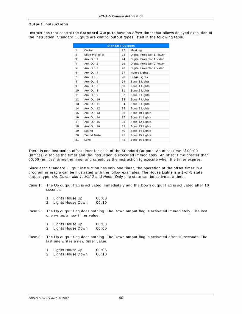
Output Instructions
Instructions that control the Standard Outputs have an offset timer that allows delayed execution ofthe instruction. Standard Outputs are control output types listed in the following table.
Standard Outputs
1 Curtain 22 Masking
2 Slide Projector 23 Digital Projector 1 Power
3 Aux Out 1 24 Digital Projector 1 Video
4 Aux Out 2 25 Digital Projector 2 Power
5 Aux Out 3 26 Digital Projector 2 Video
6 Aux Out 4 27 House Lights
7 Aux Out 5 28 Stage Lights
8 Aux Out 6 29 Zone 3 Lights
9 Aux Out 7 30 Zone 4 Lights
10 Aux Out 8 31 Zone 5 Lights
11 Aux Out 9 32 Zone 6 Lights
12 Aux Out 10 33 Zone 7 Lights
13 Aux Out 11 34 Zone 8 Lights
14 Aux Out 12 35 Zone 9 Lights
15 Aux Out 13 36 Zone 10 Lights
16 Aux Out 14 37 Zone 11 Lights
17 Aux Out 15 38 Zone 12 Lights
18 Aux Out 16 39 Zone 13 Lights
19 Sound 40 Zone 14 Lights
20 Sound Mute 41 Zone 15 Lights
21 Lens 42 Zone 16 Lights
There is one instruction offset timer for each of the Standard Outputs. An offset time of 00:00(mm:ss) disables the timer and the instruction is executed immediately. An offset time greater than00:00 (mm:ss) arms the timer and schedules the instruction to execute when the timer expires.
Since each Standard Output instruction has only one timer, the operation of the offset timer in aprogram or macro can be illustrated with the follow examples. The House Lights is a 1-of-5 stateoutput type: Up, Down, Mid 1, Mid 2 and None. Only one state can be active at a time.
Case 1: The Up output flag is activated immediately and the Down output flag is activated after 10seconds.
1 Lights House Up 00:002 Lights House Down 00:10
Case 2: The Up output flag does nothing. The Down output flag is activated immediately. The lastone writes a new timer value.
1 Lights House Up 00:002 Lights House Down 00:00
Case 3: The Up output flag does nothing. The Down output flag is activated after 10 seconds. Thelast one writes a new timer value.
1 Lights House Up 00:052 Lights House Down 00:10

eCNA-5 Cinema Automation
41EPRAD Incorporated, © 2010
Curtain
These instructions control the Curtain output flags to operate the Curtain relays for one of threestates: Open, Close and None. The offset time can be used to delay these instructions.
Curtain Open Sets the open flag; clears the close flag
Curtain Close Sets the close flag; clears the open flag
Curtain None Clears both the open and close flags
Slide Projector
This instruction controls the Slide Projector output control flag to operate the Slide Projector relay.The offset time can be used to delay the execution of this instruction.
Slide Projector On Sets the Slide Projector flag
Slide Projector Off Clears the Slide Projector flag
Aux Out
This instruction controls the Aux Out output control flags. The Aux Out control flag can be assigned toany relay. The I/O Board screens are used to configure these outputs. This instruction will operate theassigned relay(s). The offset time can be used to delay the execution of these instructions.
Aux Out d On Sets the Aux Out d flag
Aux Out d Off Clears the Aux Out d flag
* d = 1 through 16
Lights
This instruction controls the Light level output flags for each of the sixteen light zones. It operates thelight relays for one of five states: Up, Down, Mid 1, Mid 2 and None. This instruction also activateslight levels on the QDC-400 dimmer control board. The offset time can be used to delay the executionof these instructions.
House Lights Up Sets the House Lights Up flag. Clears the Mid 1, Mid 2 and Down flags
House Lights Mid 1 Sets the House Lights Mid 1 flag. Clears the Up, Mid 2 and Down flags
House Lights Mid 2 Sets the House Lights Mid 2 flag. Clears the Up, Mid 1 and Down flags
House Lights Down Sets the House Lights Down flag. Clears the Up, Mid 1 and Mid 2 flags
House Lights None Clears the Up, Mid 1, Mid 2 and Down flags
Stage Lights Up Sets the Stage Lights Up flag. Clears the Mid 1, Mid 2 and Down flags
Stage Lights Mid 1 Sets the Stage Lights Mid 1 flag. Clears the Up, Mid 2 and Down flags
Stage Lights Mid 2 Sets the Stage Lights Mid 2 flag. Clears the Up, Mid 1 and Down flags
Stage Lights Up Sets the Stage Lights Down flag. Clears the Up, Mid 1 and Mid 2 flags
Stage Lights None Clears the Up, Mid 1, Mid 2 and Down flags
Zone* Lights Down Sets the Zone Lights Up flag. Clears the Mid 1, Mid 2 and Down flags
Zone* Lights Mid 1 Sets the Zone Lights Mid 1 flag. Clears the Up, Mid 2 and Down flags
Zone* Lights Mid 2 Sets the Zone Lights Mid 2 flag. Clears the Up, Mid 1 and Down flags
Zone* Lights Up Sets the Zone Lights Down flag. Clears the Up, Mid 1 and Mid 2 flags
Zone* Lights None Clears the Up, Mid 1, Mid 2 and Down flags
* User-defined Zone names for Zones 3 through 16 will be displayed here in the editor.

eCNA-5 Cinema Automation
42EPRAD Incorporated, © 2010
Sound
This instruction controls the eight sound output control flags and which operate the sound relays. Thisinstruction also controls the Mute control flag. This instruction is normally used to select the formatand audio source on the Sound Processor. The offset time can be used to delay the execution of thisinstruction.
Sound: Non-Sync Sets the Non-Sync flag. Clears all other sound flags
Sound: Mono Sets the Mono flag. Clears all other sound flags
Sound: SVA Sets the SVA flag. Clears all other sound flags
Sound: SR Sets the SR flag. Clears all other sound flags
Sound: Digital 1 Sets the Digital 1 flag. Clears all other sound flags
Sound: Aux 1 Sets the Aux 1 flag. Clears all other sound flags
Sound: Digital 2 Sets the Digital 2 flag. Clears all other sound flags
Sound: Aux 2 Sets the Aux 2 flag. Clears all other sound flags
Sound: Mute On Sets the Mute flag and memorizes the previous sound state
Sound: Mute Off Clears the Mute flag and restores the previous sound state
Sound: None Clears all sounds flags
When using this instruction, be aware of the following rules:
• A Sound Mute On instruction will turn off any other sound output. • A Sound Mute Off instruction will cause the previous sound output to be restored.• Executing a new sound instruction, including Sound None, will not turn off the mute output. Only
a Sound Mute Off instruction will turn off mute.• When mute is on, a Sound Mute On instruction will not cause the mute output to re-pulse.
Masking
This instruction controls the Masking output control flags which operate the masking relays. Thisinstruction is normally used to control the screen masking curtains.
Masking: Flat Sets the Flat flag. Clears the Scope and Special flags
Masking: Scope Sets the Scope flag. Clears the Flat and Special flags
Masking: Special Sets the Special flag. Clears the Flat and Scope flags
Masking: None Clears the Flat, Scope and Special flags
Lens
This instruction controls the Lens output control flags which operate the lens relays.
Lens: Flat Sets the Flat flag. Clears the Scope and Special flags
Lens: Scope Sets the Scope flag. Clears the Flat and Special flags
Lens: Special Sets the Special flag. Clears the Flat and Scope flags
Lens: None Clears the Flat, Scope and Special flags
Lens/Masking
This instruction combines the Lens and Masking instructions to control the Lens and Masking outputcontrol flags which operate the lens relays.
Lens/Masking: Flat Sets the Flat flag. Clears the Scope and Special flags
Lens/Masking: Scope Sets the Scope flag. Clears the Flat and Special flags
Lens/Masking: Special Sets the Special flag. Clears the Flat and Scope flags
Lens?Masking: None Clears the Flat, Scope and Special flags
eCNA-5 Cinema Automation
43EPRAD Incorporated, © 2010
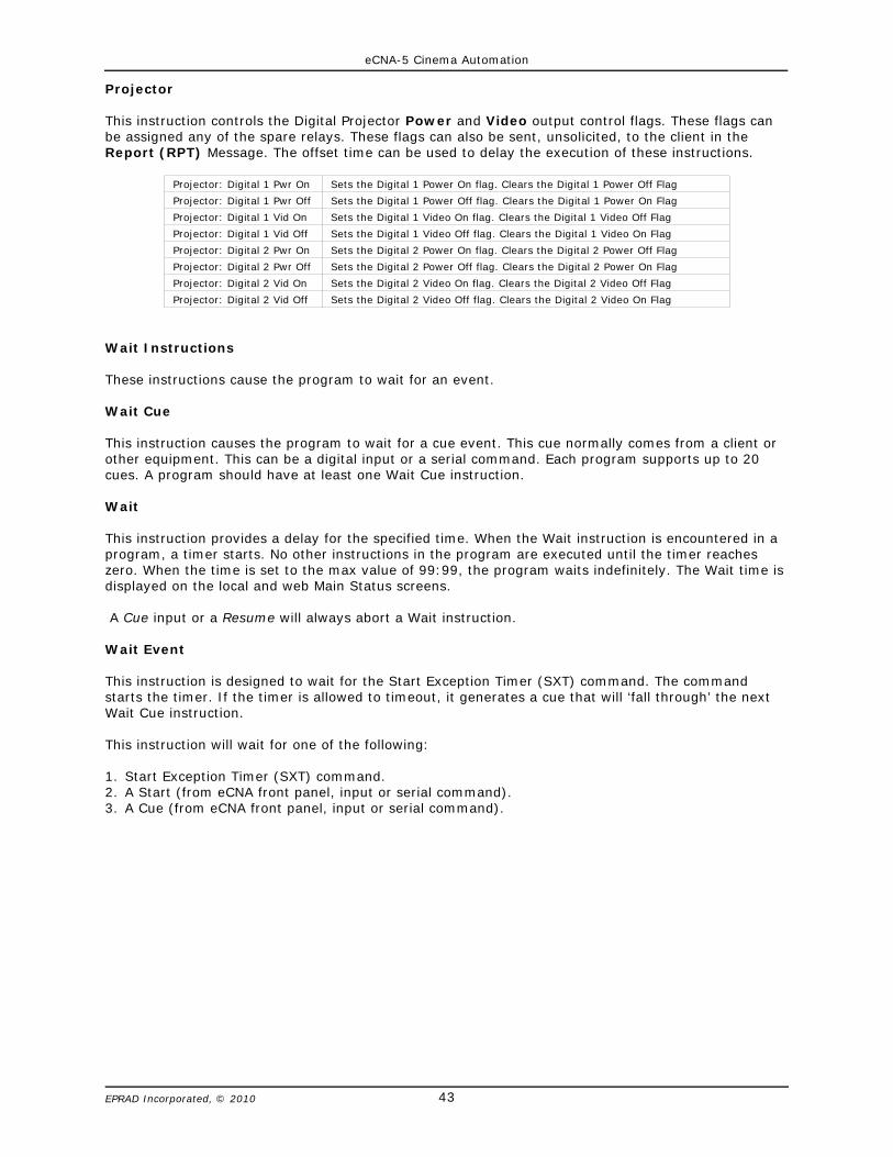
Projector
This instruction controls the Digital Projector Power and Video output control flags. These flags canbe assigned any of the spare relays. These flags can also be sent, unsolicited, to the client in theReport (RPT) Message. The offset time can be used to delay the execution of these instructions.
Projector: Digital 1 Pwr On Sets the Digital 1 Power On flag. Clears the Digital 1 Power Off Flag
Projector: Digital 1 Pwr Off Sets the Digital 1 Power Off flag. Clears the Digital 1 Power On Flag
Projector: Digital 1 Vid On Sets the Digital 1 Video On flag. Clears the Digital 1 Video Off Flag
Projector: Digital 1 Vid Off Sets the Digital 1 Video Off flag. Clears the Digital 1 Video On Flag
Projector: Digital 2 Pwr On Sets the Digital 2 Power On flag. Clears the Digital 2 Power Off Flag
Projector: Digital 2 Pwr Off Sets the Digital 2 Power Off flag. Clears the Digital 2 Power On Flag
Projector: Digital 2 Vid On Sets the Digital 2 Video On flag. Clears the Digital 2 Video Off Flag
Projector: Digital 2 Vid Off Sets the Digital 2 Video Off flag. Clears the Digital 2 Video On Flag
Wait Instructions
These instructions cause the program to wait for an event.
Wait Cue
This instruction causes the program to wait for a cue event. This cue normally comes from a client orother equipment. This can be a digital input or a serial command. Each program supports up to 20cues. A program should have at least one Wait Cue instruction.
Wait
This instruction provides a delay for the specified time. When the Wait instruction is encountered in aprogram, a timer starts. No other instructions in the program are executed until the timer reacheszero. When the time is set to the max value of 99:99, the program waits indefinitely. The Wait time isdisplayed on the local and web Main Status screens.
A Cue input or a Resume will always abort a Wait instruction.
Wait Event
This instruction is designed to wait for the Start Exception Timer (SXT) command. The commandstarts the timer. If the timer is allowed to timeout, it generates a cue that will ‘fall through’ the nextWait Cue instruction.
This instruction will wait for one of the following:
1. Start Exception Timer (SXT) command.2. A Start (from eCNA front panel, input or serial command).3. A Cue (from eCNA front panel, input or serial command).
eCNA-5 Cinema Automation
44EPRAD Incorporated, © 2010
Miscellaneous Instructions
Volume
This instruction controls the Volume level and Fade Time of the RVC-5 Remote Volume Control card.This instruction is useful for automatically changing the auditorium sound level when a different soundsource is selected.
CAI Commands
This instruction is used to Allow or Block serial control commands on a CAI communications channel.This can be useful for blocking undesired control by a client during parts of a presentation, especiallywhen more than one client is connected to the eCNA-5. This only blocks ‘control’ commands. Statuscommands are always accepted.
CAI Commands: Ch1 Block Blocks serial control commands on CAI channel 1
CAI Commands: Ch1 Allow Allows serial control commands on CAI channel 1
CAI Commands: Ch2 Block Blocks serial control commands on CAI channel 2
CAI Commands: Ch2 Allow Allows serial control commands on CAI channel 2
CAI Commands: Ch3 Block Blocks serial control commands on CAI channel 3
CAI Commands: Ch3 Allow Allows serial control commands on CAI channel 3
Segment
This instruction is used to identify the current part or segment of the presentation. The active segmentname is displayed on the local and web status screens. The segment names are defined in the inSegment Names setup screen. The client can also request the active segment with the SEGIDX andSEGTXT Status commands.
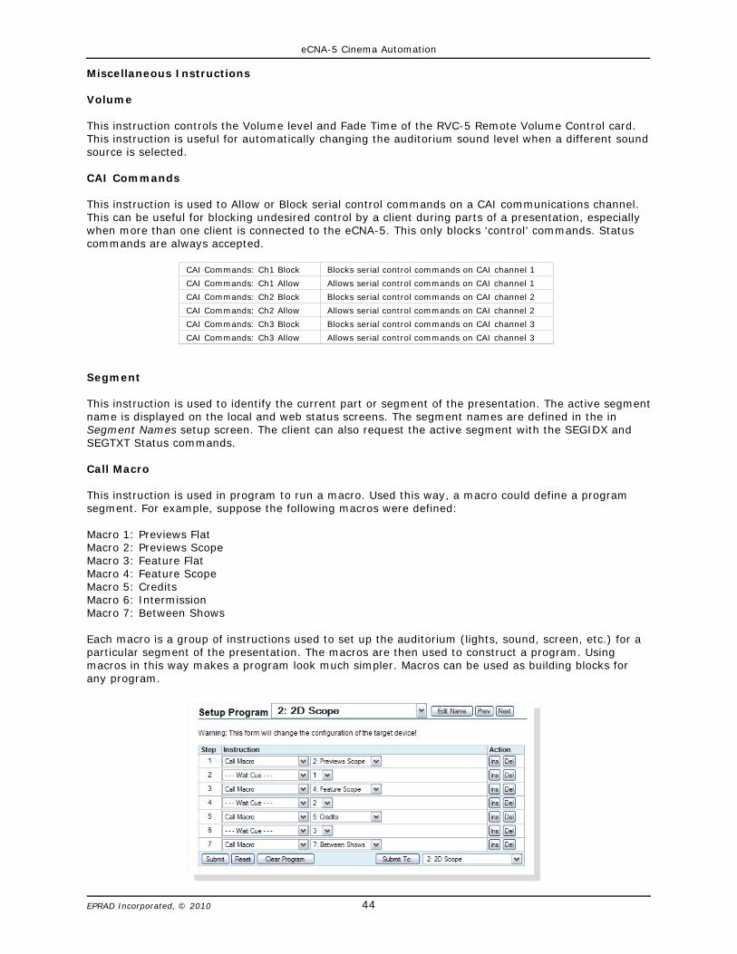
Call Macro
This instruction is used in program to run a macro. Used this way, a macro could define a programsegment. For example, suppose the following macros were defined:
Macro 1: Previews FlatMacro 2: Previews ScopeMacro 3: Feature FlatMacro 4: Feature ScopeMacro 5: CreditsMacro 6: IntermissionMacro 7: Between Shows
Each macro is a group of instructions used to set up the auditorium (lights, sound, screen, etc.) for aparticular segment of the presentation. The macros are then used to construct a program. Usingmacros in this way makes a program look much simpler. Macros can be used as building blocks forany program.
eCNA-5 Cinema Automation
45EPRAD Incorporated, © 2010
CAI Report Event
This instruction is used to generate an EVENT Report message. The message is sent to the client whenthis instruction is encountered in a program or a macro.
Set Timer
This instruction is used to set or clear the general purpose timers.
Timer
This instruction is used to pause or resume a timer.
Display Timer
This instruction allows a timer to be displayed on the local and browser status screens.
Exit If
This instruction provides a conditional exit of a macro based on an input, an output or a segment flag.If the tested condition is true, the macro is immediately exited and any instructions following the ExitIf instruction are not executed. If the tested condition is false, then the instructions following the ExitIf instruction will be executed.
Remote Device
The RemDev1 though RemDev5 instructions are used to send commands to a remote Ethernet TCPdevice. Remote Devices and commands are set up from the Remote Device Configuration screen.
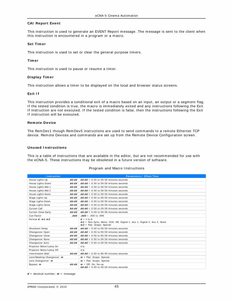
Unused Instructions
This is a table of instructions that are available in the editor, but are not recommended for use withthe eCNA-5. These instructions may be obsoleted in a future version of software.
Program and Macro Instructions
Instruction Parameters / Offset Time
House Lights Up dd:dd dd:dd = 0:00 to 59:59 minutes:seconds
House Lights Down dd:dd dd:dd = 0:00 to 59:59 minutes:seconds
House Lights Mid 1 dd:dd dd:dd = 0:00 to 59:59 minutes:seconds
House Lights Mid 2 dd:dd dd:dd = 0:00 to 59:59 minutes:seconds
House Lights None dd:dd dd:dd = 0:00 to 59:59 minutes:seconds
Stage Lights Up dd:dd dd:dd = 0:00 to 59:59 minutes:seconds
Stage Lights Down dd:dd dd:dd = 0:00 to 59:59 minutes:seconds
Stage Lights None dd:dd dd:dd = 0:00 to 59:59 minutes:seconds
Curtain Call dd:dd dd:dd = 0:00 to 59:59 minutes:seconds
Curtain Close Early dd:dd dd:dd = 0:00 to 59:59 minutes:seconds
Cue Factor .ddd .ddd = .000 to .999
Format d: m1 m2 d = 1 to 9m1 = Non-Sync; Mono; SVA; SR; Digital 1; Aux 1; Digital 2; Aux 2; None m2 = Flat; Scope; Special
Shutdown Delay dd:dd dd:dd = 0:00 to 59:59 minutes:seconds
Changeover Open dd:dd dd:dd = 0:00 to 59:59 minutes:seconds
Changeover Close dd:dd dd:dd = 0:00 to 59:59 minutes:seconds
Changeover None dd:dd dd:dd = 0:00 to 59:59 minutes:seconds
Changeover Auto dd:dd dd:dd = 0:00 to 59:59 minutes:seconds
Projector Motor/Lamp On n/a
Projector Motor/Lamp Off n/a
Intermission Wait dd:dd dd:dd = 0:00 to 99:99 minutes:seconds
Lens/Masking Changeover: m m = Flat; Scope; Special
Lens Changeover: m m = Flat; Scope; Special
Bypass: m dd:dd m = Off; On; No-opdd:dd = 0:00 to 59:59 minutes:seconds
d = decimal number; m = message
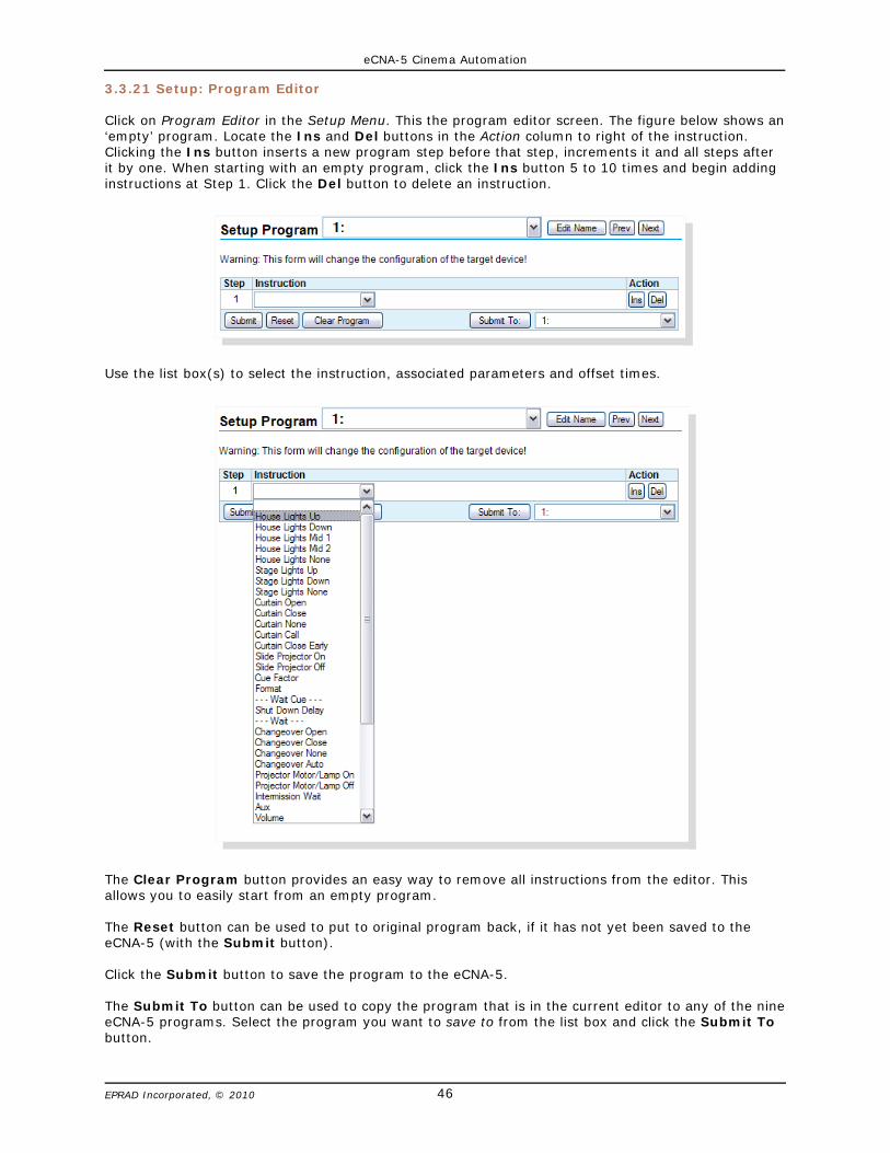
eCNA-5 Cinema Automation
46EPRAD Incorporated, © 2010
3.3.21 Setup: Program Editor
Click on Program Editor in the Setup Menu. This the program editor screen. The figure below shows an‘empty’ program. Locate the Ins and Del buttons in the Action column to right of the instruction.Clicking the Ins button inserts a new program step before that step, increments it and all steps afterit by one. When starting with an empty program, click the Ins button 5 to 10 times and begin addinginstructions at Step 1. Click the Del button to delete an instruction.
Use the list box(s) to select the instruction, associated parameters and offset times.
The Clear Program button provides an easy way to remove all instructions from the editor. Thisallows you to easily start from an empty program.
The Reset button can be used to put to original program back, if it has not yet been saved to theeCNA-5 (with the Submit button).
Click the Submit button to save the program to the eCNA-5.
The Submit To button can be used to copy the program that is in the current editor to any of the nineeCNA-5 programs. Select the program you want to save to from the list box and click the Submit Tobutton.

eCNA-5 Cinema Automation
47EPRAD Incorporated, © 2010
The program editor screen allows you to assign meaningful names to programs with up to 14characters of text. Click the Edit Name button to type the program name into the Combo Box. Use theCombo Box to select the program to edit.
For example, a program could be named “3D Scope”.
3.3.22 Setup: Macro Editor
The macro editor screen allows you to create up to 30 macros. This screen is almost identical to theProgram Editor screen.
Click on Macro Editor in the Setup Menu. This the macro editor screen. Locate the Ins and Delbuttons in the Action column to right of the instruction. Clicking the Ins button inserts a new programstep before that step, increments it and all steps after it by one. When starting with an emptyprogram, click the Ins button a few times and begin adding instructions at Step 1. Click the Delbutton to delete an instruction. Macros are limited to a maximum of 15 instructions.
The macro editor screen also allows you to assign meaningful names to macros with up to 14characters of text. Click the Edit Name button to type the program name into the Combo Box. Use theCombo Box to select the macro to edit. This is helpful when assigning macros to triggers.
A Macro is a group of instructions similar to a program. Macros, however, are used much differentlythan programs. A macro can be run anytime while the eCNA is in progress (running a program),faulted, stopped or in the idle state. Macros can be initiated by the Call Macro program instruction, theMacro serial command or a Trigger event.

eCNA-5 Cinema Automation
48EPRAD Incorporated, © 2010
4. Status
Click STATUS to get to the Status Menu. The Status Menu is along the left side of the screen: MainStatus, Network Monitor, Local I/O Network, Ethernet Network, System Control Detail andI/O Flag Detail. Each option contains screens that will provide status of the eCNA-5.
4.1 Status: Main Status
Click on Main Status in the Status Menu. This screen displays information during and between showsproviding feedback of show progress, sound and picture format, current show segment, programnumber and step, cue number and fault conditions.
When the Web Keys in System Parameters are Enabled, the manual control buttons, as defined inSystem Parameters, will be available along the bottom of this screen.
eCNA-5 Cinema Automation
49EPRAD Incorporated, © 2010
4.1.1 Status and Fault Messages
Memory Faults
User configuration data is stored in battery-back memory. A checksum is calculated on a block of dataeach time new data is saved. The checksum is re-calculated on a power up and compared to theprevious saved checksum. If there is a mis-match, a fault is generated. Any of the following memoryfaults indicate that configuration data has changed. Any memory fault will prevent a program frombeing started. The fault must be cleared before starting a program. Although a Cancel will clear thefault and allow a program start, this does not fix the checksum mis-match. So the next power cyclewill generate a new memory fault. The only way to fix this is to force a new checksum calculation bysaving new data. The best way to do this is to restore data from your backup.
MEM FAULT:SYSTEM This indicates a System Parameters Memory Fault.
MEM FAULT:PROG d-dd This indicates a Program Memory Fault where d-dd is the program and stepnumber of the first occurrence of corrupt user data.
MEM FAULT:MACR d-dd This indicates a Macro Memory Fault where d-dd is the macro and stepnumber of the first occurrence of corrupt user data. LOW BATTERY FAULT The Low Battery Fault indicates that the battery fell below the thresholdvoltage during a power down condition. This message would usually be accompanied by one or morememory faults.
CHECK RTC SETTINGS This message is displayed if the hardware clock and the software clock differby more than 60 seconds. This normally won’t happen because the software clock is set by readingthe hardware clock on a power up. Thereafter, the hardware clock is set when the NTP time isreceived.
NTP SERVER NOT FOUND This message is displayed if the eCNA is configured to be an NTP client,the NTP IP address is not 0.0.0.0 and the NTP server is not responding. The message is activated ifthere are three consecutive NTP server timeouts.
LIN: NETWORK FAULT This message is displayed to indicate a loss of communications with a LocalI/O Network (LIN) device. This fault will cause a program shutdown or prevent a program fromstarting. This is a latched fault and a Cancel input is required to clear the fault.
FIRE ALARM STOP This message indicates a fire stop input, which would normally come from thefire alarm system. This is a latched fault and a Cancel input is required to clear the fault.
LIN REMOTE STOP This is a status message only. This message indicates that a stop input from aLocal I/O Network (LIN) device is activated. This message has a three second re-triggerable one-shot.
LIN REMOTE START This is a status message only. This message indicates that a start input from aLocal I/O Network (LIN) device is activated. This message has a three second re-triggerable one-shot.
LIN REMOTE CANCEL INPUT This is a status message only. This message indicates that a cancelinput from a Local I/O Network (LIN) device is activated. This message has a three second re-triggerable one-shot.
CAI d REMOTE STOP This is a status message only where d is 1, 2 or 3. This message indicates thata stop input was received from a Cinema Automation Interface (CAI) channel. This message has athree second re-triggerable one-shot.
CAI d REMOTE START This is a status message only where d is 1, 2 or 3. This message indicatesthat a start input was received from a Cinema Automation Interface (CAI) channel. This message hasa three second re-triggerable one-shot.

eCNA-5 Cinema Automation
50EPRAD Incorporated, © 2010
DIGITAL d FAULT This message is displayed to indicate that a digital input fault was activatedwhere d is 1 or 2. This fault will cause a program shutdown or prevent a program from starting. Thisfault can be configured to be a latched fault requiring a Cancel to clear the fault. See ‘Digital FaultInput Latched’ on the Setup: System Parameters screen.
CAI d FAULT This message is displayed to indicate that a digital input fault was activated where d is1, 2 or 3. This fault will cause a program shutdown or prevent a program from starting.
IP ADDRESS CONFLICT This message indicates that more than one eCNA-5 is configured with thesame IP Address.
SCREEN ID CONFLICT This message indicates that more the one eCNA-5 is configured with thesame Screen Id. See Configuration DIP Switches on the Main CPU Board.
PROGRAM ABORT INPUT This is a status message only. This message indicates that an abort wasactivated. This message has a three second re-triggerable one-shot.
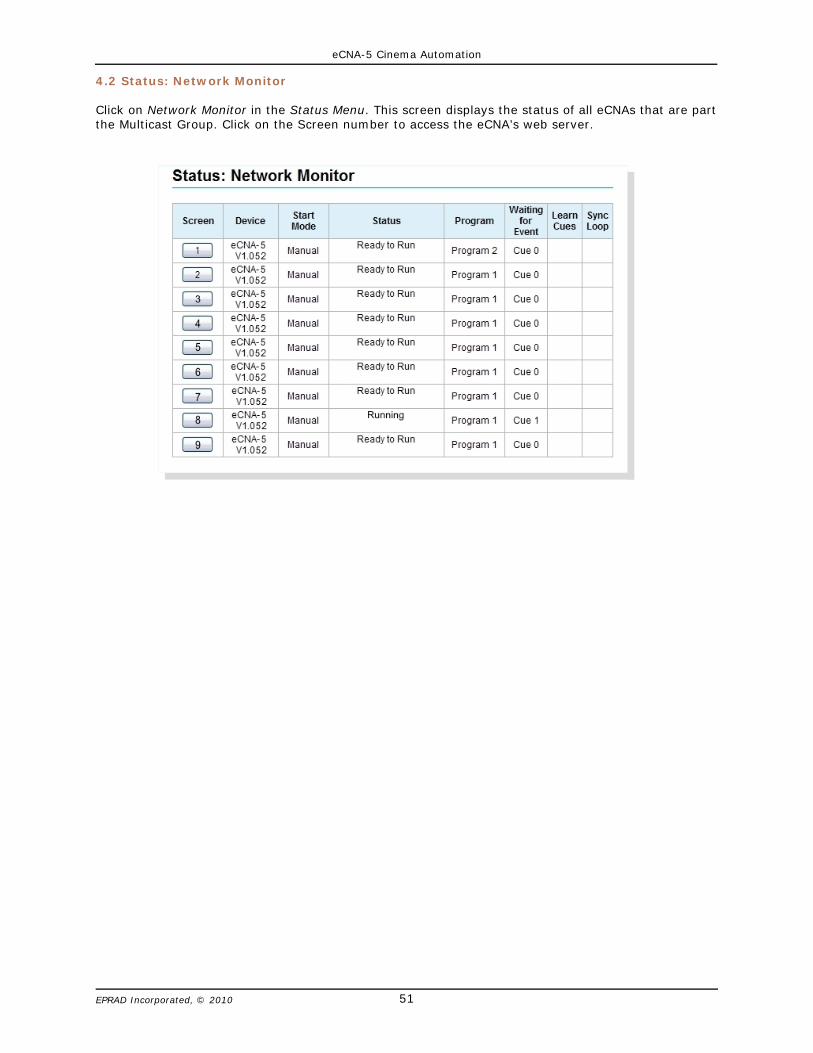
eCNA-5 Cinema Automation
51EPRAD Incorporated, © 2010
4.2 Status: Network Monitor
Click on Network Monitor in the Status Menu. This screen displays the status of all eCNAs that are partthe Multicast Group. Click on the Screen number to access the eCNA’s web server.
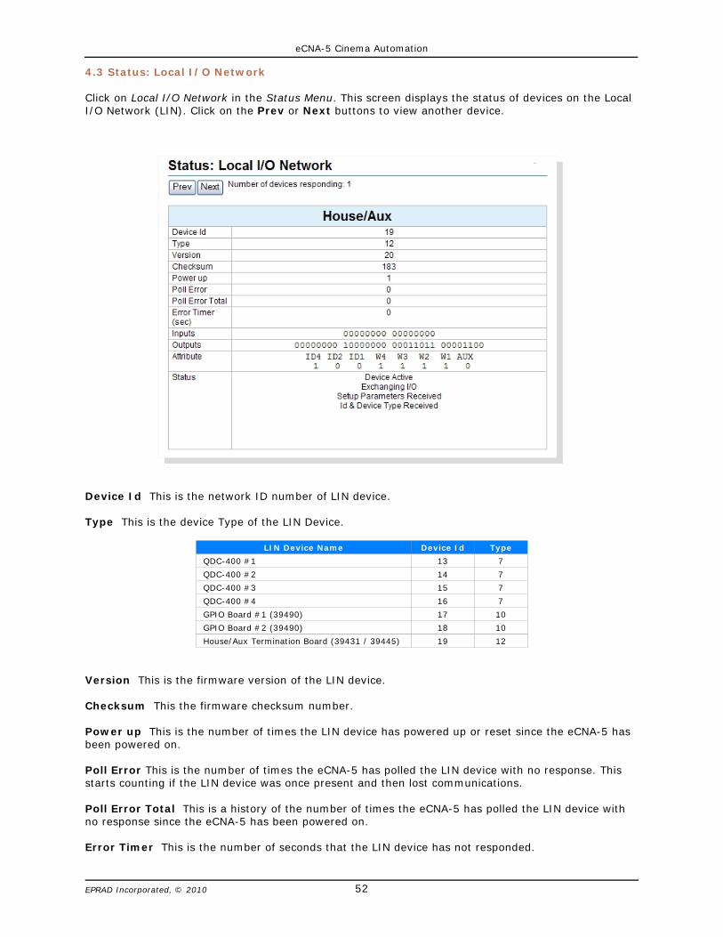
eCNA-5 Cinema Automation
52EPRAD Incorporated, © 2010
4.3 Status: Local I/O Network
Click on Local I/O Network in the Status Menu. This screen displays the status of devices on the LocalI/O Network (LIN). Click on the Prev or Next buttons to view another device.
Device Id This is the network ID number of LIN device.
Type This is the device Type of the LIN Device.
LIN Device Name Device Id Type
QDC-400 #1 13 7
QDC-400 #2 14 7
QDC-400 #3 15 7
QDC-400 #4 16 7
GPIO Board #1 (39490) 17 10
GPIO Board #2 (39490) 18 10
House/Aux Termination Board (39431 / 39445) 19 12
Version This is the firmware version of the LIN device.
Checksum This the firmware checksum number.
Power up This is the number of times the LIN device has powered up or reset since the eCNA-5 hasbeen powered on.
Poll Error This is the number of times the eCNA-5 has polled the LIN device with no response. Thisstarts counting if the LIN device was once present and then lost communications.
Poll Error Total This is a history of the number of times the eCNA-5 has polled the LIN device withno response since the eCNA-5 has been powered on.
Error Timer This is the number of seconds that the LIN device has not responded.

eCNA-5 Cinema Automation
53EPRAD Incorporated, © 2010
Inputs This string of digits represent the actual state of the inputs. A “1" represents an input that ispresent. A “0" represents an input that is not present.
House/Aux Board Inputs
Outputs This string of digits represent the actual state of the relay outputs. A ‘1' represents anoutput that is on. A ‘0' represents an output that is off.
House/Aux Board Outputs
Attribute The attribute bits indicate the state of any configuration DIP switches and jumpers.
Status These messages are displayed based on internal status flags.
Device ActiveExchanging I/O
Setup Parameters ReceivedId & Device Type Received
Wrong Device TypeCommunications Link ErrorNot Responding Regularly

eCNA-5 Cinema Automation
54EPRAD Incorporated, © 2010
4.4 Status: Ethernet Network
Click on Ethernet Network in the Status Menu. This screen displays the connection status of theavailable ports. The Connection History column displays the last five IP addresses of the devices thathave been connected since the eCNA-5 has been powered on.
4.5 Status: Event Log
Click on Event Log in the Status Menu. This screen is used to download Event Logs from the eCNA-5.Select the number of records to retrieve and click on the Download Event Log Data button to eitherOpen or Save the Event data.
Save: By default, the event logs are saved as a .csv (comma separated values) file. This is an ASCIItext file that can be imported into any spreadsheet program.
Open: The event log records will be opened by the application that has the ‘csv’ file type association.

eCNA-5 Cinema Automation
55EPRAD Incorporated, © 2010
4.6 Status: System Control Detail
Click on System Control Detail in the Status Menu. This screen displays the status of the ten generalpurpose timers and a history of executed Triggers and Macros. This screen is useful for developing anddebugging your application.
Timers
This table displays the status of the ten General Purpose Timers (GPT).
Trigger/Macro History
This table displays the history of macros and triggers in the order they were executed.
# This column displays a number that increments to 99 and wraps. This is just a reference numberthat helps you keep track of the data.
Type This column displays either the trigger or the macro that was executed.
Cause This column displays the corresponding event, trigger or communications channel thatgenerated or caused the macro or trigger.
Action This column displays the macro that was executed as a result of the trigger.
Triggers are abbreviated as Txx, where xx is the trigger number. Macros are abbreviated as Mxx,where xx is the macro number. Programs are abbreviated as Px-yy, where x is the program numberand yy is the step number.
The eCNA maintains a local buffer that stores a full tables’ worth a data. The Clear Table button onlyclears the table, not the eCNA buffer data. The Refresh Table button retrieves all buffer data. ThePause Display button allows you to freeze the table data on the screen.

eCNA-5 Cinema Automation
56EPRAD Incorporated, © 2010
4.7 Status: I/O Flag Detail
Click on I/O Flag Detail in the Status Menu. This screen displays the current states of the StandardInput and Output flags.
The screen also allows Administrators to override the Standard Outputs when the S2-1 DIP switch andWeb Keys are both Enabled. The override buttons are not shown if these permissions are not enabled.
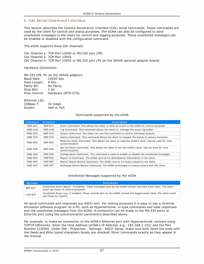
eCNA-5 Cinema Automation
57EPRAD Incorporated, © 2010
5. CAI Serial Command Interface
This section describes the Cinema Automation Interface (CAI) serial commands. These commands areused by the client for control and status purposes. The eCNA can also be configured to sendunsolicited messages to the client for control and logging purposes. These unsolicited messages canbe enabled or disabled with the configuration command.
The eCNA supports three CAI channels:
CAI Channel 1: TCP Port 13000 or RS-232 port (P9)CAI Channel 2: TCP Port 13001CAI Channel 3: TCP Port 13002 or RS-232 port (P1 on the 39446 optional adapter board)
Hardware Connection:
RS-232 (P9, P1 on the 39446 adapter):Baud Rate: 19200 bpsData Length: 8 bitsParity Bit: No ParityStop Bits: 1 bitFlow Control: Hardware (RTS-CTS)
Ethernet (J2):10Base-T: 10 mbpsDuplex: Half or Full
Commands supported by the eCNA
Command Response Description
CMD EVT RSP EVT Event Command. This allows the client to send an event to the eCNA for control purposes
CMD LOG RSP LOG Log Command. This command allows the client to manage the event log buffer.
CMD OUT RSP OUT Output Command. The client can use this command to control individual outputs.
CMD STS RSP STS Status Command. This command allows the client to request the status of various functions.
CMD RCK RSP RCKRead the Clock Command. This allows the client to read the eCNA’s clock. Can be used for timesynchronization.
CMD SCK RSP SCK Set the Clock Command. This allows the client to set the eCNA’s clock. Can be used for timesynchronization.
CMD CFG RSP CFG Configuration Command. This command is used to enable or disable the unsolicited messages.
CMD RID RSP RID Report Id Command. The eCNA returns it’s identification information to the client.
CMD RST RSP RST Report Status Record Command. The eCNA returns it’s status record to the client.
CMD XST RSP XST Exchange Status Record Command. The eCNA exchanges it’s status record with the client.
Unsolicited Messages supported by the eCNA
Message Description
RPT EVT Unsolicited Event Report. If enabled, These messages sent by the eCNA contain real time event data. The clientcould use these for control purposes.
LOG EVT Unsolicited Event Log. If enabled, These records sent by the eCNA contain the logged event data. The client coulduse these for reports.
All serial commands and responses are ASCII text. For testing purposes it is easy to use a terminalemulation software program on a PC, such as Hyperterminal, to type commands and view responsesand the unsolicited messages from the eCNA. A connection can be made to the RS-232 ports orEthernet port using the communication parameters described above.
For example, to make an connection to the eCNA’s Ethernet port with Hyperterminal, connect usingTCP/IP (Winsock). Enter the Host Address (eCNA’s IP Address, e.g., 192.168.1.101) and the PortNumber (13000). Under File - Properties - Settings - ASCII Setup, make sure both Send line ends withline feeds and Echo typed characters locally are checked. Enter commands exactly as they appear inthe manual.

eCNA-5 Cinema Automation
58EPRAD Incorporated, © 2010
Important Client Application Notes
1) A CAI channel will timeout after one minute. However, the connection timeout logic allows theconnection to remain open even if the connection has timed out to allow sending unsolicitedreports. But be aware, that the eCNA will close the TCP/IP connection if it is timed out and anotherclient requests the resource. It may be desirable to periodically send a command to the port inorder to maintain ownership of the resource.
In the case where the eCNA communications resource is already being used (open and not timedout) by Client A and Client B tries to connect, the error response (RSP,ERR,0,998,ResourceUnavailable,828<CR><LF>) is sent back to Client B. The connection to Client A is unaffected.
2) The third parameter in all commands is the Packet Sequence Number (PSN). The PSN is atwo-byte number (0 to 65535) that should wrap at 65535. The eCNA puts the Client’s commandPSN in all responses to the Client. The PSN can be used to match responses with commands. TheClient may increment the PSN for each new command it transmits. Incrementing PSN is optionaland if not used just fix it at 0.
3) A checksum calculation by the client is optional. If ?? is used in the command instead of achecksum, the command is executed. The eCNA interprets this as a ‘don’t care’ value for thechecksum. This method is not recommended because it does not insure proper message errorchecking. However it may be acceptable for TCP/IP communications.
4) The Request Response parameter (Y or N) appears in a command just before the checksum. Thisinstructs the eCNA to either send a response or not. This is available for all commands that do notrequest information from the eCNA.
The response is only an acknowledgment that the command was received and not that it wasnecessarily executed. The Report Event message or Status command can be utilized to determineexecution.
5) Commands exceeding 132 characters including the terminating carriage return and line feed arediscarded by the eCNA. Commands must not contain the NULL character (0x00) anywhere in thecommand line.
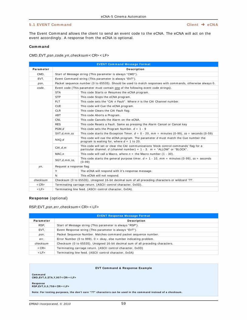
eCNA-5 Cinema Automation
59EPRAD Incorporated, © 2010
5.1 EVENT Command Client þ eCNA
The Event Command allows the client to send an event code to the eCNA. The eCNA will act on theevent accordingly. A response from the eCNA is optional.
Command
CMD,EVT,psn,code,yn,checksum<CR><LF>
EVENT Command Message Format
Parameter Description
CMD, Start of Message string (This parameter is always “CMD”).
EVT, Event Command string (This parameter is always “EVT”).
psn, Packet sequence number (0 to 65535). Should be used to match responses with commands, otherwise always 0.
code, Event code (This parameter must contain one of the following event code strings).
STA This code Starts or Resumes the eCNA program.
STP This code Stops the eCNA program.
FLT This code sets the “CAI n Fault”. Where n is the CAI Channel number.
CUE This code will Cue the eCNA program.
CLR This code Clears the CAI Fault flag.
ABT This code Aborts a Program.
CNL This code Cancels the Alarm on the eCNA.
RES This code Resets a Fault. Same as pressing the Alarm Cancel or Cancel key
PGM,d This code sets the Program Number. d = 1 - 9
SXT,d,mm,ss This code starts the Exception Timer. d = 0 - 20, mm = minutes (0-99), ss = seconds (0-59)
NXQ,d This code will cue the eCNA program. The parameter d must match the Cue number theprogram is waiting for, where d = 1 to 20.
CAI,d,m This code will set or clear the CAI communications ‘block control commands’ flag for aparticular channel. d (channel number) = 1 - 3. m = “ALLOW” or “BLOCK”.
MAC,n This code will call a Macro, where n = the Macro number (1 - 30).
SGT,d,mm,ss, This code starts the general purpose timer. d = 1 - 10, mm = minutes (0-99), ss = seconds(0-99)
yn, Request a response flag.
Y The eCNA will respond with it’s response message.
N This eCNA will not respond.
checksum Checksum (0 to 65535). Unsigned 16-bit decimal sum of all preceding characters or wildcard ‘??’.
<CR> Terminating carriage return. (ASCII control character, 0x0D).
<LF> Terminating line feed. (ASCII control character, 0x0A).
Response (optional)
RSP,EVT,psn,err,checksum<CR><LF>
EVENT Response Message Format
Parameter Description
RSP, Start of Message string (This parameter is always “RSP”).
EVT, Event Response string (This parameter is always “EVT”).
psn, Packet Sequence Number. Matches command packet sequence number.
err, Error Number (0 to 999). 0 = okay, else number indicating problem.
checksum Checksum (0 to 65535). Unsigned 16-bit decimal sum of all preceding characters.
<CR> Terminating carriage return. (ASCII control character, 0x0D)
<LF> Terminating line feed. (ASCII control character, 0x0A)
EVT Command & Response Example
CommandCMD,EVT,0,STA,Y,907<CR><LF>
ResponseRSP,EVT,0,0,756<CR><LF>
Note: For testing purposes, the don’t care “??” characters can be used in the command instead of a checksum.
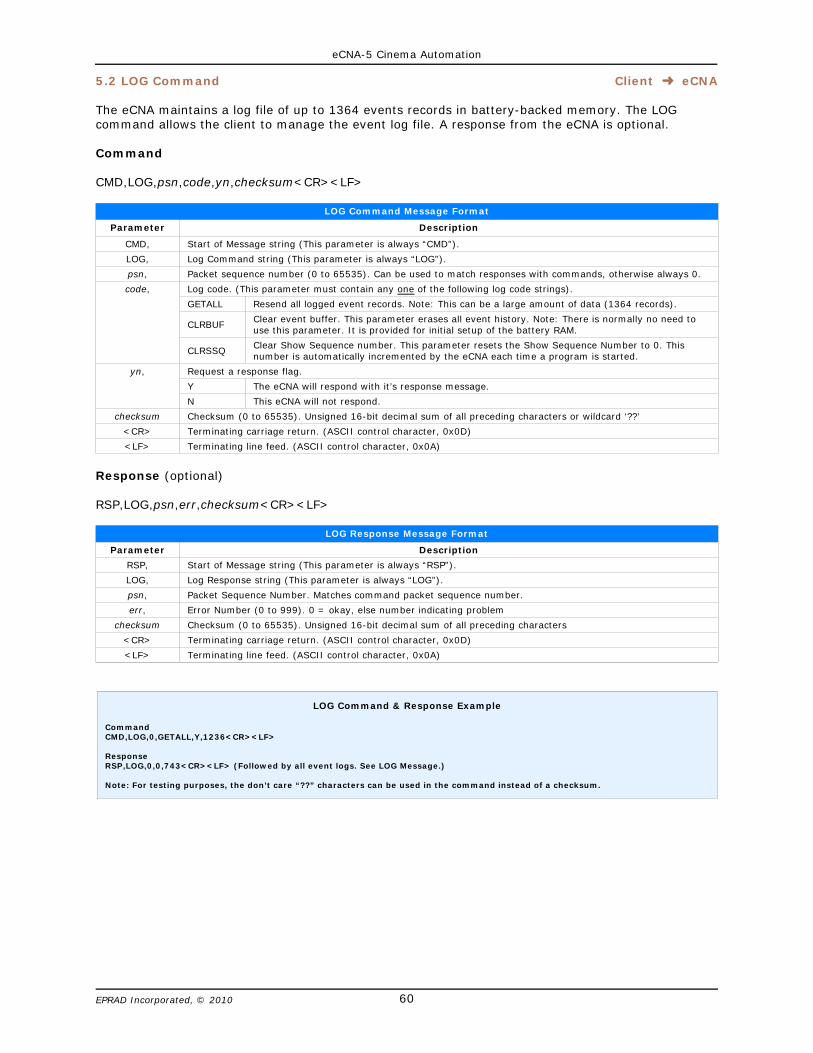
eCNA-5 Cinema Automation
60EPRAD Incorporated, © 2010
5.2 LOG Command Client þ eCNA
The eCNA maintains a log file of up to 1364 events records in battery-backed memory. The LOGcommand allows the client to manage the event log file. A response from the eCNA is optional.
Command
CMD,LOG,psn,code,yn,checksum<CR><LF>
LOG Command Message Format
Parameter Description
CMD, Start of Message string (This parameter is always “CMD”).
LOG, Log Command string (This parameter is always “LOG”).
psn, Packet sequence number (0 to 65535). Can be used to match responses with commands, otherwise always 0.
code, Log code. (This parameter must contain any one of the following log code strings).
GETALL Resend all logged event records. Note: This can be a large amount of data (1364 records).
CLRBUF Clear event buffer. This parameter erases all event history. Note: There is normally no need touse this parameter. It is provided for initial setup of the battery RAM.
CLRSSQ Clear Show Sequence number. This parameter resets the Show Sequence Number to 0. Thisnumber is automatically incremented by the eCNA each time a program is started.
yn, Request a response flag.
Y The eCNA will respond with it’s response message.
N This eCNA will not respond.
checksum Checksum (0 to 65535). Unsigned 16-bit decimal sum of all preceding characters or wildcard ‘??’
<CR> Terminating carriage return. (ASCII control character, 0x0D)
<LF> Terminating line feed. (ASCII control character, 0x0A)
Response (optional)
RSP,LOG,psn,err,checksum<CR><LF>
LOG Response Message Format
Parameter Description
RSP, Start of Message string (This parameter is always “RSP”).
LOG, Log Response string (This parameter is always “LOG”).
psn, Packet Sequence Number. Matches command packet sequence number.
err, Error Number (0 to 999). 0 = okay, else number indicating problem
checksum Checksum (0 to 65535). Unsigned 16-bit decimal sum of all preceding characters
<CR> Terminating carriage return. (ASCII control character, 0x0D)
<LF> Terminating line feed. (ASCII control character, 0x0A)
LOG Command & Response Example
CommandCMD,LOG,0,GETALL,Y,1236<CR><LF>
ResponseRSP,LOG,0,0,743<CR><LF> (Followed by all event logs. See LOG Message.)
Note: For testing purposes, the don’t care “??” characters can be used in the command instead of a checksum.

eCNA-5 Cinema Automation
61EPRAD Incorporated, © 2010
5.3 CONFIGURATION Command Client þ eCNA
The Configuration command allows the client to enable or disable the unsolicited messages sent bythe eCNA. A response from the eCNA is optional.
Command
CMD,CFG,psn,code,yn,checksum<CR><LF>
CONFIGURATION Command Message Format
Parameter Description
CMD, Start of Message string (This parameter is always “CMD”).
CFG, Configuration Command string (This parameter is always “CFG”).
psn, Packet sequence number (0 to 65535). Can be used to match responses with commands, otherwise always 0.
code, Configuration code. (This parameter must contain any one of the following configuration code strings).
RPTOFF Event Reports Off.
RPTON Event Reports On
LOGOFF Event Log Off
LOGON Event Log On
OPT1OFF Disables logging of Macro calls (Event #95)
OPT1ON Enables logging of Macro calls (Event #95)
yn, Request a response flag.
Y The eCNA will respond with it’s response message.
N This eCNA will not respond.
checksum Checksum (0 to 65535). Unsigned 16-bit decimal sum of all preceding characters or wildcard ‘??’
<CR> Terminating carriage return. (ASCII control character, 0x0D)
<LF> Terminating line feed. (ASCII control character, 0x0A)
Response (optional)
RSP,CFG,psn,err,checksum<CR><LF>
CONFIGURATION Response Message Format
Parameter Description
RSP, Start of Message string (This parameter is always “RSP”).
CFG, Configuration Response string (This parameter is always “CFG”).
psn, Packet Sequence Number. Matches command packet sequence number.
err, Error Number (0 to 999). 0 = okay, else number indicating problem
checksum Checksum (0 to 65535). Unsigned 16-bit decimal sum of all preceding characters
<CR> Terminating carriage return. (ASCII control character, 0x0D)
<LF> Terminating line feed. (ASCII control character, 0x0A)
CFG Command & Response Example
CommandCMD,CFG,0,LOGON,Y,1160<CR><LF>
ResponseRSP,CFG,0,0,725<CR><LF>
Note: For testing purposes, the don’t care “??” characters can be used in the command instead of a checksum.
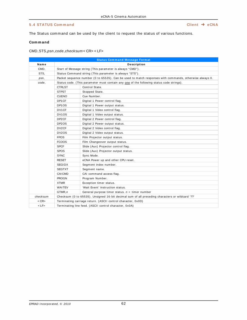
eCNA-5 Cinema Automation
62EPRAD Incorporated, © 2010
5.4 STATUS Command Client þ eCNA
The Status command can be used by the client to request the status of various functions.
Command
CMD,STS,psn,code,checksum<CR><LF>
Status Command Message Format
Name Description
CMD, Start of Message string (This parameter is always “CMD”).
STS, Status Command string (This parameter is always “STS”).
psn, Packet sequence number (0 to 65535). Can be used to match responses with commands, otherwise always 0.
code, Status code. (This parameter must contain any one of the following status code strings).
CTRLST Control State.
STPST Stopped State.
CUENO Cue Number.
DP1CF Digital 1 Power control flag.
DP1OS Digital 1 Power output status.
DV1CF Digital 1 Video control flag.
DV1OS Digital 1 Video output status.
DP2CF Digital 2 Power control flag.
DP2OS Digital 2 Power output status.
DV2CF Digital 2 Video control flag.
DV2OS Digital 2 Video output status.
FPOS Film Projector output status.
FCOOS Film Changeover output status.
SPCF Slide (Aux) Projector control flag.
SPOS Slide (Aux) Projector output status.
SYNC Sync Mode.
RESET eCNA Power up and other CPU reset.
SEGIDX Segment index number.
SEGTXT Segment name.
CAICMD CAI command access flag.
PROGN Program Number.
XTMR Exception timer status.
WAITEV ‘Wait Event’ instruction status.
GTMR,n General purpose timer status. n = timer number
checksum Checksum (0 to 65535). Unsigned 16-bit decimal sum of all preceding characters or wildcard ‘??’
<CR> Terminating carriage return. (ASCII control character, 0x0D)
<LF> Terminating line feed. (ASCII control character, 0x0A)
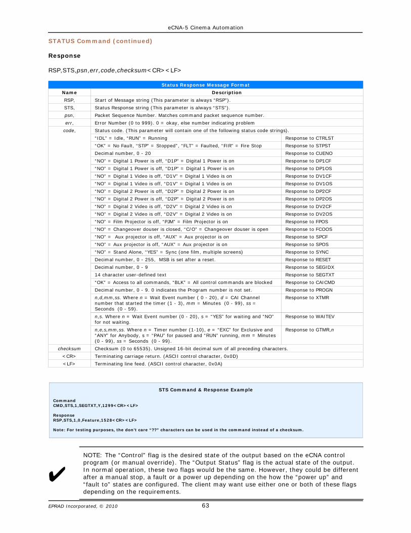
eCNA-5 Cinema Automation
63EPRAD Incorporated, © 2010
STATUS Command (continued)
Response
RSP,STS,psn,err,code,checksum<CR><LF>
Status Response Message Format
Name Description
RSP, Start of Message string (This parameter is always “RSP”).
STS, Status Response string (This parameter is always “STS”).
psn, Packet Sequence Number. Matches command packet sequence number.
err, Error Number (0 to 999). 0 = okay, else number indicating problem
code, Status code. (This parameter will contain one of the following status code strings).
“IDL” = Idle, “RUN” = Running Response to CTRLST
“OK” = No Fault, “STP” = Stopped”, “FLT” = Faulted, “FIR” = Fire Stop Response to STPST
Decimal number, 0 - 20 Response to CUENO
“NO” = Digital 1 Power is off, “D1P” = Digital 1 Power is on Response to DP1CF
“NO” = Digital 1 Power is off, “D1P” = Digital 1 Power is on Response to DP1OS
“NO” = Digital 1 Video is off, “D1V” = Digital 1 Video is on Response to DV1CF
“NO” = Digital 1 Video is off, “D1V” = Digital 1 Video is on Response to DV1OS
“NO” = Digital 2 Power is off, “D2P” = Digital 2 Power is on Response to DP2CF
“NO” = Digital 2 Power is off, “D2P” = Digital 2 Power is on Response to DP2OS
“NO” = Digital 2 Video is off, “D2V” = Digital 2 Video is on Response to DV2CF
“NO” = Digital 2 Video is off, “D2V” = Digital 2 Video is on Response to DV2OS
“NO” = Film Projector is off, “PJM” = Film Projector is on Response to FPOS
“NO” = Changeover douser is closed, “C/O” = Changeover douser is open Response to FCOOS
“NO” = Aux projector is off, “AUX” = Aux projector is on Response to SPCF
“NO” = Aux projector is off, “AUX” = Aux projector is on Response to SPOS
“NO” = Stand Alone, “YES” = Sync (one film, multiple screens) Response to SYNC
Decimal number, 0 - 255, MSB is set after a reset. Response to RESET
Decimal number, 0 - 9 Response to SEGIDX
14 character user-defined text Response to SEGTXT
“OK” = Access to all commands, “BLK” = All control commands are blocked Response to CAICMD
Decimal number, 0 - 9. 0 indicates the Program number is not set. Response to PROGN
n,d,mm,ss. Where n = Wait Event number ( 0 - 20), d = CAI Channelnumber that started the timer (1 - 3), mm = Minutes (0 - 99), ss =Seconds (0 - 59).
Response to XTMR
n,s. Where n = Wait Event number (0 - 20), s = “YES” for waiting and “NO”for not waiting.
Response to WAITEV
n,e,s,mm,ss. Where n = Timer number (1-10), e = “EXC” for Exclusive and“ANY” for Anybody, s = “PAU” for paused and “RUN” running, mm = Minutes(0 - 99), ss = Seconds (0 - 99).
Response to GTMR,n
checksum Checksum (0 to 65535). Unsigned 16-bit decimal sum of all preceding characters.
<CR> Terminating carriage return. (ASCII control character, 0x0D)
<LF> Terminating line feed. (ASCII control character, 0x0A)
U
STS Command & Response Example
CommandCMD,STS,1,SEGTXT,Y,1299<CR><LF>
ResponseRSP,STS,1,0,Feature,1528<CR><LF>
Note: For testing purposes, the don’t care “??” characters can be used in the command instead of a checksum.
NOTE: The “Control” flag is the desired state of the output based on the eCNA controlprogram (or manual override). The “Output Status” flag is the actual state of the output.In normal operation, these two flags would be the same. However, they could be differentafter a manual stop, a fault or a power up depending on the how the “power up” and“fault to” states are configured. The client may want use either one or both of these flagsdepending on the requirements.
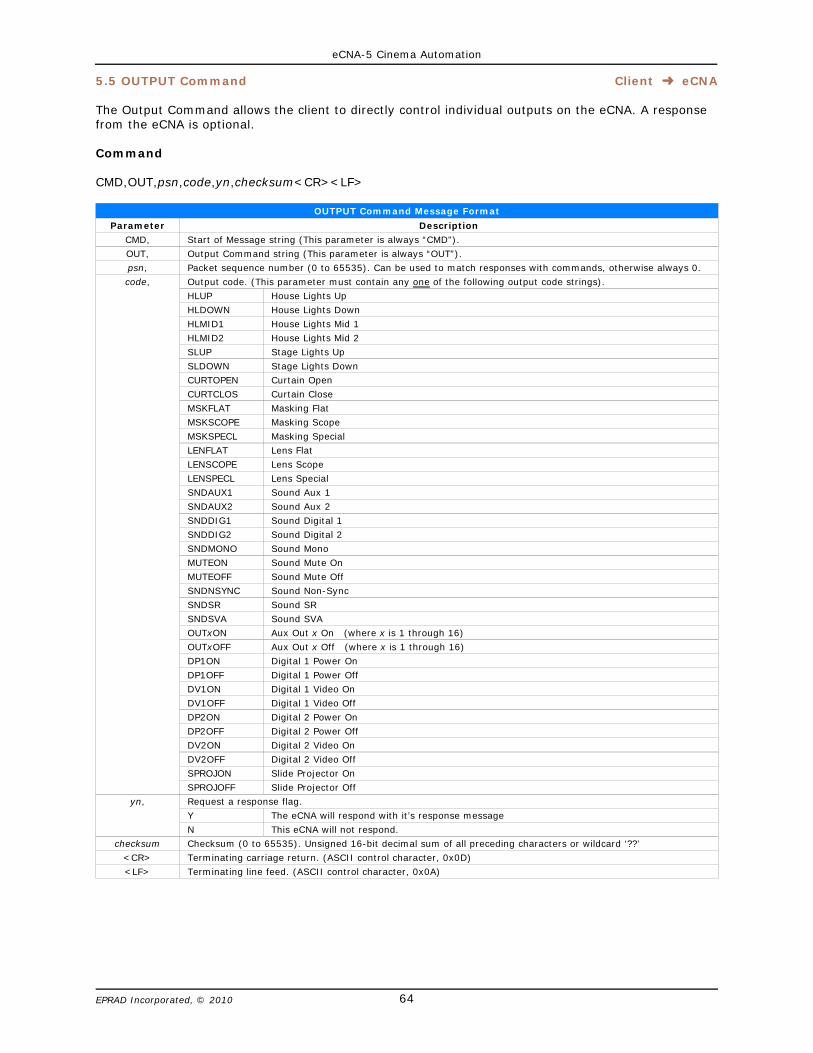
eCNA-5 Cinema Automation
64EPRAD Incorporated, © 2010
5.5 OUTPUT Command Client þ eCNA
The Output Command allows the client to directly control individual outputs on the eCNA. A responsefrom the eCNA is optional.
Command
CMD,OUT,psn,code,yn,checksum<CR><LF>
OUTPUT Command Message Format
Parameter Description
CMD, Start of Message string (This parameter is always “CMD”).
OUT, Output Command string (This parameter is always “OUT”).
psn, Packet sequence number (0 to 65535). Can be used to match responses with commands, otherwise always 0.
code, Output code. (This parameter must contain any one of the following output code strings).
HLUP House Lights Up
HLDOWN House Lights Down
HLMID1 House Lights Mid 1
HLMID2 House Lights Mid 2
SLUP Stage Lights Up
SLDOWN Stage Lights Down
CURTOPEN Curtain Open
CURTCLOS Curtain Close
MSKFLAT Masking Flat
MSKSCOPE Masking Scope
MSKSPECL Masking Special
LENFLAT Lens Flat
LENSCOPE Lens Scope
LENSPECL Lens Special
SNDAUX1 Sound Aux 1
SNDAUX2 Sound Aux 2
SNDDIG1 Sound Digital 1
SNDDIG2 Sound Digital 2
SNDMONO Sound Mono
MUTEON Sound Mute On
MUTEOFF Sound Mute Off
SNDNSYNC Sound Non-Sync
SNDSR Sound SR
SNDSVA Sound SVA
OUTxON Aux Out x On (where x is 1 through 16)
OUTxOFF Aux Out x Off (where x is 1 through 16)
DP1ON Digital 1 Power On
DP1OFF Digital 1 Power Off
DV1ON Digital 1 Video On
DV1OFF Digital 1 Video Off
DP2ON Digital 2 Power On
DP2OFF Digital 2 Power Off
DV2ON Digital 2 Video On
DV2OFF Digital 2 Video Off
SPROJON Slide Projector On
SPROJOFF Slide Projector Off
yn, Request a response flag.
Y The eCNA will respond with it’s response message
N This eCNA will not respond.
checksum Checksum (0 to 65535). Unsigned 16-bit decimal sum of all preceding characters or wildcard ‘??’
<CR> Terminating carriage return. (ASCII control character, 0x0D)
<LF> Terminating line feed. (ASCII control character, 0x0A)
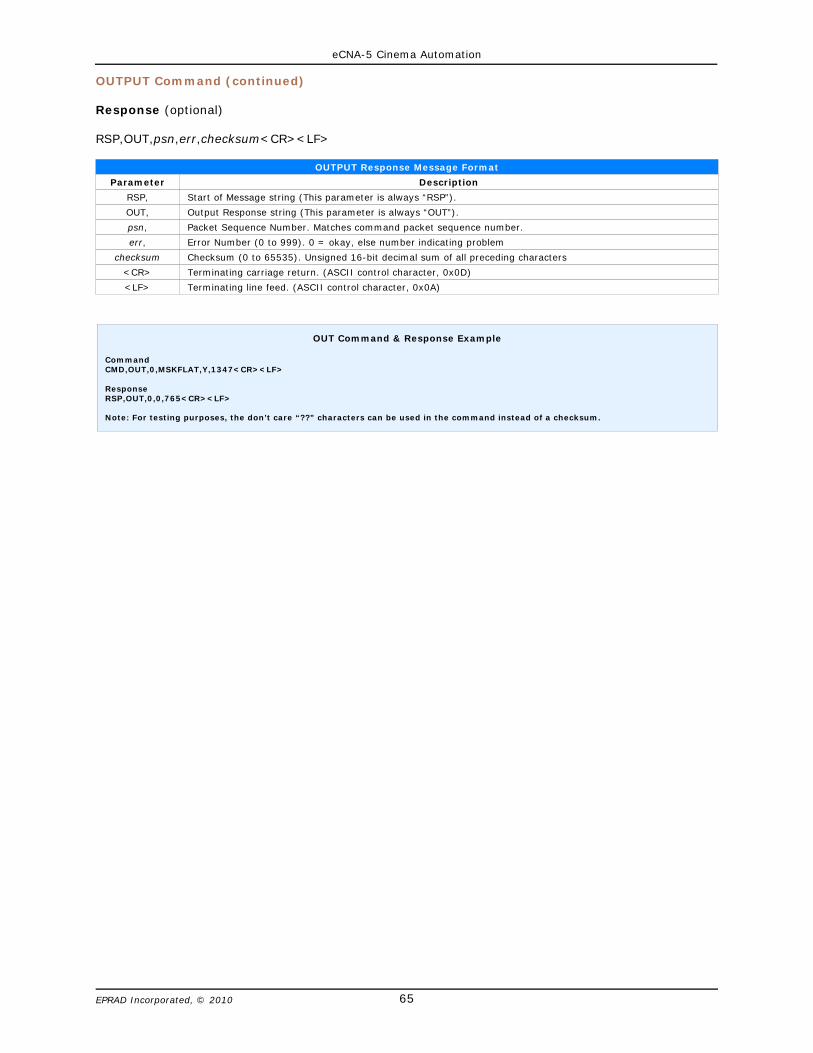
eCNA-5 Cinema Automation
65EPRAD Incorporated, © 2010
OUTPUT Command (continued)
Response (optional)
RSP,OUT,psn,err,checksum<CR><LF>
OUTPUT Response Message Format
Parameter Description
RSP, Start of Message string (This parameter is always “RSP”).
OUT, Output Response string (This parameter is always “OUT”).
psn, Packet Sequence Number. Matches command packet sequence number.
err, Error Number (0 to 999). 0 = okay, else number indicating problem
checksum Checksum (0 to 65535). Unsigned 16-bit decimal sum of all preceding characters
<CR> Terminating carriage return. (ASCII control character, 0x0D)
<LF> Terminating line feed. (ASCII control character, 0x0A)
OUT Command & Response Example
CommandCMD,OUT,0,MSKFLAT,Y,1347<CR><LF>
ResponseRSP,OUT,0,0,765<CR><LF>
Note: For testing purposes, the don’t care “??” characters can be used in the command instead of a checksum.
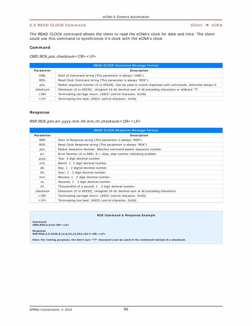
eCNA-5 Cinema Automation
66EPRAD Incorporated, © 2010
5.6 READ CLOCK Command Client þ eCNA
The READ CLOCK command allows the client to read the eCNA’s clock for date and time. The clientcould use this command to synchronize it’s clock with the eCNA’s clock.
Command
CMD,RCK,psn,checksum<CR><LF>
READ CLOCK Command Message Format
Parameter Description
CMD, Start of Command string (This parameter is always “CMD”).
RCK, Read Clock Command string (This parameter is always “RCK”).
psn, Packet sequence number (0 to 65535). Can be used to match responses with commands, otherwise always 0.
checksum Checksum (0 to 65535). Unsigned 16-bit decimal sum of all preceding characters or wildcard ‘??’
<CR> Terminating carriage return. (ASCII control character, 0x0D)
<LF> Terminating line feed. (ASCII control character, 0x0A)
Response
RSP,RCK,psn,err,yyyy,mm,hh,mm,ttt,checksum<CR><LF>
READ CLOCK Response Message Format
Parameter Description
RSP, Start of Response string (This parameter is always “RSP”).
RCK, Read Clock Response string (This parameter is always “RCK”).
psn, Packet Sequence Number. Matches command packet sequence number.
err, Error Number (0 to 999). 0 = okay, else number indicating problem
yyyy, Year. 4 digit decimal number.
mm, Month. 1- 2 digit decimal number.
dd, Day. 1 - 2 digital decimal number.
hh, Hour. 1 - 2 digit decimal number.
mm, Minutes. 1 - 2 digit decimal number.
ss, Seconds. 1 - 2 digit decimal number.
ttt, Thousandths of a second. 1 - 3 digit decimal number.
checksum Checksum (0 to 65535). Unsigned 16-bit decimal sum of all preceding characters
<CR> Terminating carriage return. (ASCII control character, 0x0D)
<LF> Terminating line feed. (ASCII control character, 0x0A)
RCK Command & Response Example
CommandCMD,RCK,0,616<CR><LF>
ResponseRSP,RCK,0,0,2008,6,12,8,53,12,253,1817<CR><LF>
Note: For testing purposes, the don’t care “??” characters can be used in the command instead of a checksum.
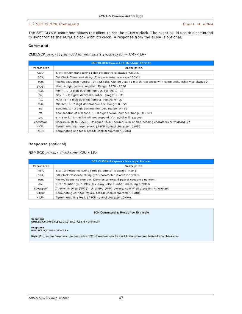
eCNA-5 Cinema Automation
67EPRAD Incorporated, © 2010
5.7 SET CLOCK Command Client þ eCNA
The SET CLOCK command allows the client to set the eCNA’s clock. The client could use this commandto synchronize the eCNA’s clock with it’s clock. A response from the eCNA is optional.
Command
CMD,SCK,psn,yyyy,mm,dd,hh,mm,ss,ttt,yn,checksum<CR><LF>
SET CLOCK Command Message Format
Parameter Description
CMD, Start of Command string (This parameter is always “CMD”).
SCK, Set Clock Command string (This parameter is always “SCK”).
psn, Packet sequence number (0 to 65535). Can be used to match responses with commands, otherwise always 0.
yyyy, Year. 4 digit decimal number. Range: 1970 - 2036
mm, Month. 1- 2 digit decimal number. Range: 1 - 12
dd, Day. 1 - 2 digital decimal number. Range: 1 - 31
hh, Hour. 1 - 2 digit decimal number. Range: 0 - 23
mm, Minutes. 1 - 2 digit decimal number. Range: 0 - 59
ss, Seconds. 1 - 2 digit decimal number. Range: 0 - 59
ttt, Thousandths of a second. 1 - 3 digit decimal number. Range: 0 - 999
yn, a = Y or N. N= eCNA will not respond. Y = eCNA will respond.
checksum Checksum (0 to 65535). Unsigned 16-bit decimal sum of all preceding characters or wildcard ‘??’
<CR> Terminating carriage return. (ASCII control character, 0x0D)
<LF> Terminating line feed. (ASCII control character, 0x0A)
Response (optional)
RSP,SCK,psn,err,checksum<CR><LF>
SET CLOCK Response Message Format
Parameter Description
RSP, Start of Response string (This parameter is always “RSP”).
SCK, Set Clock Response string (This parameter is always “SCK”).
psn, Packet Sequence Number. Matches command packet sequence number.
err, Error Number (0 to 999). 0 = okay, else number indicating problem
checksum Checksum (0 to 65535). Unsigned 16-bit decimal sum of all preceding characters
<CR> Terminating carriage return. (ASCII control character, 0x0D).
<LF> Terminating line feed. (ASCII control character, 0x0A).
SCK Command & Response Example
CommandCMD,SCK,0,2008,6,12,10,12,43,0,Y,1476<CR><LF>
ResponseRSP,SCK,0,0,742<CR><LF>
Note: For testing purposes, the don’t care “??” characters can be used in the command instead of a checksum.

eCNA-5 Cinema Automation
68EPRAD Incorporated, © 2010
5.8 REPORT ID Command Client þ eCNA
The REPORT ID command allows the client get the eCNA’s identification record. The eCNA returns it’sDevice Name, Software Version and Screen Id Number.
Command
CMD,RID,psn,checksum<CR><LF>
REPORT ID Command Message Format
Parameter Description
CMD, Start of Command string (This parameter is always “CMD”).
RID, Report Id Command string (This parameter is always “RID”).
psn, Packet sequence number (0 to 65535). Can be used to match responses with commands, otherwise always 0.
checksum Checksum (0 to 65535). Unsigned 16-bit decimal sum of all preceding characters or wildcard ‘??’
<CR> Terminating carriage return. (ASCII control character, 0x0D).
<LF> Terminating line feed. (ASCII control character, 0x0A).
Response
RSP,RID,psn,err,record,checksum<CR><LF>
REPORT ID Response Message Format
Parameter Description
RSP, Start of Response string (This parameter is always “RSP”).
RID, Report Id Response string (This parameter is always “RID”).
psn, Packet sequence number (0 to 65535). Can be used to match responses with commands, otherwise always 0.
err, Error Number (0 to 999). 0 = okay, else number indicating problem.
record, eCNA Id Record. (This record will contain all of the following code strings).
code 1,code 2,code 3
Device name = “eCNA-5". ASCII Text. Max. Length = 8 characters.Software version. ASCII Text. Max. Length = 6 characters.Screen Id. Decimal number: 0 to 63. Max length = 2 characters.
checksum Checksum (0 to 65535). Unsigned 16-bit decimal sum of all preceding characters or wildcard ‘??’
<CR> Terminating carriage return. (ASCII control character, 0x0D).
<LF> Terminating line feed. (ASCII control character, 0x0A).
RID Command & Response Example
CommandCMD,RID,0,615<CR><LF>
ResponseRSP,RID,0,0,eCNA-5,1007,27,1630<CR><LF>
Note: For testing purposes, the don’t care “??” characters can be used in the command instead of a checksum.
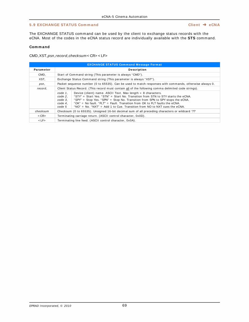
eCNA-5 Cinema Automation
69EPRAD Incorporated, © 2010
5.9 EXCHANGE STATUS Command Client þ eCNA
The EXCHANGE STATUS command can be used by the client to exchange status records with theeCNA. Most of the codes in the eCNA status record are individually available with the STS command.
Command
CMD,XST,psn,record,checksum<CR><LF>
EXCHANGE STATUS Command Message Format
Parameter Description
CMD, Start of Command string (This parameter is always “CMD”).
XST, Exchange Status Command string (This parameter is always “XST”).
psn, Packet sequence number (0 to 65535). Can be used to match responses with commands, otherwise always 0.
record, Client Status Record. (This record must contain all of the following comma delimited code strings).
code 1,code 2,code 3,code 4,code 5
Device (client) name. ASCII Text. Max length = 8 characters.“STY” = Start Yes. “STN” = Start No. Transition from STN to STY starts the eCNA.“SPY” = Stop Yes. “SPN” = Stop No. Transition from SPN to SPY stops the eCNA.“OK” = No fault. “FLT” = Fault. Transition from OK to FLT faults the eCNA.“NO” = No. “NXT” = Add 1 to Cue. Transition from NO to NXT cues the eCNA.
checksum Checksum (0 to 65535). Unsigned 16-bit decimal sum of all preceding characters or wildcard ‘??’
<CR> Terminating carriage return. (ASCII control character, 0x0D).
<LF> Terminating line feed. (ASCII control character, 0x0A).

eCNA-5 Cinema Automation
70EPRAD Incorporated, © 2010
EXCHANGE STATUS Command (continued)
Response
RSP,XST,psn,err,record,checksum<CR><LF>
EXCHANGE STATUS Response Message Format
Parameter Description
RSP, Start of Response string (This parameter is always “RSP”).
XST, Exchange Status Response string (This parameter is always “XST”).
psn, Packet sequence number (0 to 65535). Can be used to match responses with commands, otherwise always 0.
err, Error Number (0 to 999). 0 = okay, else number indicating problem.
record, eCNA Status Record. (This record will contain all of the following comma delimited code strings).
code 1,code 2,code 3,code 4,code 5,code 6,code 7,code 8,code 9,code 10,code 11,code 12,code 13,code 14,code 15,code 16,code 17,code 18,code 19,code 20,code 21,code 22,code 23,code 24,code 25,code 26,code 27,
code 28,code 29,code 30,code 31,code 32,code 33
CAI control flag. “ENA” = CAI Enabled, “DIS” = CAI Disabled. (See Main CPU Board S2-8)Control state. “IDL” = Idle , “RUN” = Running.Stopped state. “OK” = No Fault, “STP” = Stopped, “FLT” = Faulted, “FIR” = Fire Stop.Cue number. Decimal number: 0 to 20.Digital 1 Power control flag. “NO” = Off, “D1P” = OnDigital 1 Power output status. “NO” = Off, “D1P” = OnDigital 1 Video control flag. “NO” = Off, “D1V” = OnDigital 1 Video output status. “NO” = Off, “D1V” = OnDigital 2 Power control flag. “NO” = Off, “D2P” = OnDigital 2 Power output status. “NO” = Off, “D2P” = OnDigital 2 Video control flag. “NO” = Off, “D2V” = OnDigital 2 Video output status. “NO” = Off, “D2V” = On*Film Projector output status. “NO” = Off, “PJM” = On*Film Changeover output status. “NO” = Closed, “C/O” = OpenSlide (Aux) Projector control flag. “NO” = Off, “AUX” = OnSlide (Aux) Projector output status. “NO” = Off, “AUX” = On*Sync Mode. “NO” = Stand Alone, “YES” = Sync (one film, multiple screens)*Synced House Id. Decimal number, 0 = Not used, 1 to 63 = Screen Id*Synced House Id. Decimal number, 0 = Not used, 1 to 63 = Screen Id*Synced House Id. Decimal number, 0 = Not used, 1 to 63 = Screen Id*Synced House Id. Decimal number, 0 = Not used, 1 to 63 = Screen Id*Synced House Id. Decimal number, 0 = Not used, 1 to 63 = Screen IdReset. Decimal number, 0 - 255, MSB is set after a reset.*Bypass flag. “BPN” = Not Active, “BPY” = ActivatedSegment index number. Decimal number, 0 - 9Segment name. Up to 14 character user-defined text CAI Command Access Flag. “OK” = Access to all commands, “BLK” = All control commands areblocked.Program Number. Decimal number 1 - 9CAI Channel Number that started the Exception Timer. Decimal number, 1,2 or 3Exception Timer Minutes (Ticking down). Decimal number, 0 - 99Exception Timer Seconds (Ticking down). Decimal number, 0 -59‘Wait Event: n’ Instruction Status. “YES” = Waiting, “NO” = Not Waiting‘Wait Event: n’ Instruction Event number n. (Cleared on program start).
checksum Checksum (0 to 65535). Unsigned 16-bit decimal sum of all preceding characters or wildcard ‘??’
<CR> Terminating carriage return. (ASCII control character, 0x0D).
<LF> Terminating line feed. (ASCII control character, 0x0A).* Not applicable to the eCNA-5.
XST Command & Response Example
CommandCMD,XST,0,Client 1,STN,SPN,OK,NO,2352<CR><LF>
ResponseRSP,XST,0,0,ENA,IDL,OK,0,NO,NO,D1V,D1V,NO,NO,NO,NO,NO,NO,NO,NO,NO,0,0,0,0,0,7,BPN,Between Shows,OK,6723<CR><LF>
Note: For testing purposes, the don’t care “??” characters can be used in the command instead of a checksum.
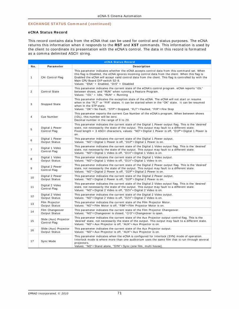
eCNA-5 Cinema Automation
71EPRAD Incorporated, © 2010
EXCHANGE STATUS Command (continued)
eCNA Status Record
This record contains data from the eCNA that can be used for control and status purposes. The eCNAreturns this information when it responds to the RST and XST commands. This information is used bythe client to coordinate its presentation with the eCNA’s control. The data in this record is formattedas a comma delimited ASCII string.
eCNA Status Record
No. Parameter Description
1 CAI Control Flag
This parameter indicates whether the eCNA accepts control data from this command set. Whenthis flag is Disabled, the eCNA ignores incoming control data from the client. When this flag isEnabled the eCNA will accept valid control data from the client. This flag is controlled by with theMain CPU Board DIP switch S2-8.Values: “ENA” = Enabled, “DIS” = Disabled
2 Control StateThis parameter indicates the current state of the eCNA's control program. eCNA reports “IDL”between shows, and “RUN” when running a Feature Program. Values: "IDL" = Idle, "RUN" = Running
3 Stopped State
This parameter indicates the exception state of the eCNA. The eCNA will not start or resumewhen in the “FLT” or “FIR” states. It can be started when in the “OK” state. It can be resumedwhen in the STP state.Values: “OK“=No Fault, “STP”=Stopped, “FLT”=Faulted, “FIR”=Fire Stop
4 Cue NumberThis parameter reports the current Cue Number of the eCNA’s program. When between shows(IDL), this number will be zero. Decimal number in the range of 0 to 20.
5 Digital 1 PowerControl Flag
This parameter indicates the current state of the Digital 1 Power output flag. This is the 'desired'state, not necessarily the state of the output. This output may fault to a different state.Fixed length = 3 ASCII characters, values: “NO”=Digital 1 Power is off, “D1P”=Digital 1 Power ison.
6 Digital 1 PowerOutput Status
This parameter indicates the current state of the Digital 1 Power output.Values: “NO”=Digital 1 Power is off, “D1P”=Digital 1 Power is on.
7 Digital 1 VideoControl Flag
This parameter indicates the current state of the Digital 1 Video output flag. This is the 'desired'state, not necessarily the state of the output. This output may fault to a different state.Values: “NO”=Digital 1 Video is off, “D1V”=Digital 1 Video is on.
8 Digital 1 VideoOutput Status
This parameter indicates the current state of the Digital 1 Video output.Values: “NO”=Digital 1 Video is off, “D1V”=Digital 1 Video is on.
9 Digital 2 PowerControl Flag
This parameter indicates the current state of the Digital 2 Power output flag. This is the 'desired'state, not necessarily the state of the output. This output may fault to a different state.Values: “NO”=Digital 2 Power is off, “D2P”=Digital 2 Power is on.
10 Digital 2 PowerOutput Status
This parameter indicates the current state of the Digital 2 Power output.Values: “NO”=Digital 2 Power is off, “D2P”=Digital 2 Power is on.
11 Digital 2 VideoControl Flag
This parameter indicates the current state of the Digital 2 Video output flag. This is the 'desired'state, not necessarily the state of the output. This output may fault to a different state.Values: “NO”=Digital 2 Video is off, “D2V”=Digital 2 Video is on.
12 Digital 2 VideoOutput Status
This parameter indicates the current state of the Digital 2 Video output.Values: “NO”=Digital 2 Video is off, “D2V”=Digital 2 Video is on.
13 Film ProjectorOutput Status
This parameter indicates the current state of the Film Projector Motor.Values: “NO”=Film Motor is off, “PJM”=Film Projector Motor is on.
14 Film ChangeoverOutput Status
This parameter indicates the current state of the Film Projector Changeover. Values: “NO”=Changeover is closed, “C/O”=Changeover is open.
15 Slide (Aux) ProjectorControl Flag
This parameter indicates the current state of the Aux Projector output control flag. This is the'desired' state, not necessarily the state of the output. This output may fault to a different state.Values: “NO”=Aux Projector is off, “AUX”=Aux Projector is on.
16 Slide (Aux) ProjectorOutput Status
This parameter indicates the current state of the Aux Projector output. Values: “NO”=Aux Projector is off, “AUX”=Aux Projector is on.
17 Sync Mode
This parameter indicates when the eCNA is configured for Interlock (SYN) mode of operation. Interlock mode is where more than one auditorium uses the same film that is run through severalprojectors.Values: “NO“=Stand alone, “SYN”=Sync (one film, multi house).
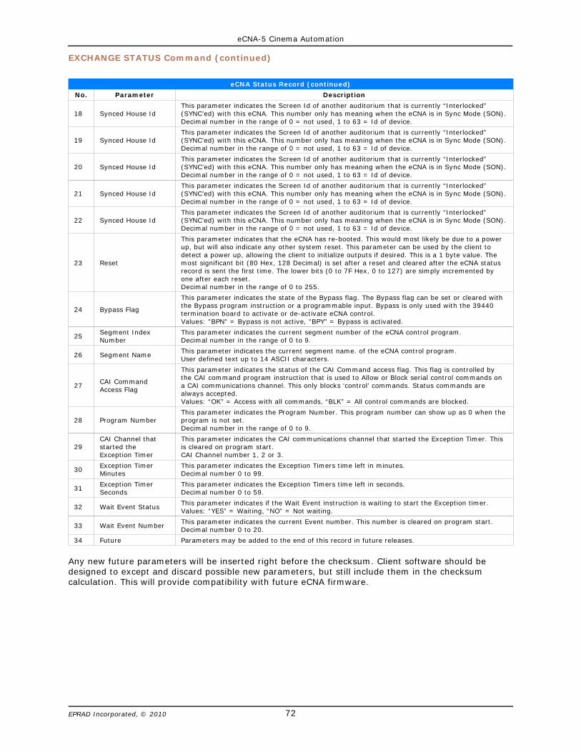
eCNA-5 Cinema Automation
72EPRAD Incorporated, © 2010
EXCHANGE STATUS Command (continued)
eCNA Status Record (continued)
No. Parameter Description
18 Synced House IdThis parameter indicates the Screen Id of another auditorium that is currently “Interlocked”(SYNC’ed) with this eCNA. This number only has meaning when the eCNA is in Sync Mode (SON).Decimal number in the range of 0 = not used, 1 to 63 = Id of device.
19 Synced House IdThis parameter indicates the Screen Id of another auditorium that is currently “Interlocked”(SYNC’ed) with this eCNA. This number only has meaning when the eCNA is in Sync Mode (SON).Decimal number in the range of 0 = not used, 1 to 63 = Id of device.
20 Synced House IdThis parameter indicates the Screen Id of another auditorium that is currently “Interlocked”(SYNC’ed) with this eCNA. This number only has meaning when the eCNA is in Sync Mode (SON).Decimal number in the range of 0 = not used, 1 to 63 = Id of device.
21 Synced House IdThis parameter indicates the Screen Id of another auditorium that is currently “Interlocked”(SYNC’ed) with this eCNA. This number only has meaning when the eCNA is in Sync Mode (SON).Decimal number in the range of 0 = not used, 1 to 63 = Id of device.
22 Synced House IdThis parameter indicates the Screen Id of another auditorium that is currently “Interlocked”(SYNC’ed) with this eCNA. This number only has meaning when the eCNA is in Sync Mode (SON).Decimal number in the range of 0 = not used, 1 to 63 = Id of device.
23 Reset
This parameter indicates that the eCNA has re-booted. This would most likely be due to a powerup, but will also indicate any other system reset. This parameter can be used by the client todetect a power up, allowing the client to initialize outputs if desired. This is a 1 byte value. Themost significant bit (80 Hex, 128 Decimal) is set after a reset and cleared after the eCNA statusrecord is sent the first time. The lower bits (0 to 7F Hex, 0 to 127) are simply incremented byone after each reset. Decimal number in the range of 0 to 255.
24 Bypass Flag
This parameter indicates the state of the Bypass flag. The Bypass flag can be set or cleared withthe Bypass program instruction or a programmable input. Bypass is only used with the 39440termination board to activate or de-activate eCNA control. Values: "BPN" = Bypass is not active, "BPY" = Bypass is activated.
25 Segment IndexNumber
This parameter indicates the current segment number of the eCNA control program. Decimal number in the range of 0 to 9.
26 Segment Name This parameter indicates the current segment name. of the eCNA control program.User defined text up to 14 ASCII characters.
27 CAI CommandAccess Flag
This parameter indicates the status of the CAI Command access flag. This flag is controlled bythe CAI command program instruction that is used to Allow or Block serial control commands ona CAI communications channel. This only blocks ‘control’ commands. Status commands arealways accepted.Values: “OK” = Access with all commands, “BLK” = All control commands are blocked.
28 Program NumberThis parameter indicates the Program Number. This program number can show up as 0 when theprogram is not set. Decimal number in the range of 0 to 9.
29CAI Channel thatstarted theException Timer
This parameter indicates the CAI communications channel that started the Exception Timer. Thisis cleared on program start.CAI Channel number 1, 2 or 3.
30 Exception TimerMinutes
This parameter indicates the Exception Timers time left in minutes.Decimal number 0 to 99.
31 Exception TimerSeconds
This parameter indicates the Exception Timers time left in seconds.Decimal number 0 to 59.
32 Wait Event Status This parameter indicates if the Wait Event instruction is waiting to start the Exception timer.Values: “YES” = Waiting, “NO” = Not waiting.
33 Wait Event Number This parameter indicates the current Event number. This number is cleared on program start.Decimal number 0 to 20.
34 Future Parameters may be added to the end of this record in future releases.
Any new future parameters will be inserted right before the checksum. Client software should bedesigned to except and discard possible new parameters, but still include them in the checksumcalculation. This will provide compatibility with future eCNA firmware.

eCNA-5 Cinema Automation
73EPRAD Incorporated, © 2010
5.10 REPORT STATUS Command Client þ eCNA
The REPORT STATUS command can be used by the client to request the status record from the eCNA.Most of the codes in the eCNA status record are individually available with the STS command.
Command
CMD,RST,psn,checksum<CR><LF>
REPORT STATUS Command Message Format
Parameter Description
CMD, Start of Command string (This parameter is always “CMD”).
RST, Exchange Status Command string (This parameter is always “RST”).
psn, Packet sequence number (0 to 65535). Can be used to match responses with commands, otherwise always 0.
checksum Unsigned 16-bit decimal sum of all preceding characters or wildcard ‘??’
<CR> Terminating carriage return. (ASCII control character, 0x0D).
<LF> Terminating line feed. (ASCII control character, 0x0A).
Response
RSP,RST,psn,err,record,checksum<CR><LF>
REPORT STATUS Response Message Format
Parameter Description
RSP, Start of Response string (This parameter is always “RSP”).
RST, Exchange Status Response string (This parameter is always “RST”).
psn, Packet sequence number (0 to 65535). Can be used to match responses with commands, otherwise always 0.
err, Error Number (0 to 999). 0 = okay, else number indicating problem.
record, eCNA Status Record. (This record will contain all of the following comma delimited code strings).
code 1,code 2,code 3,code 4,code 5,code 6,code 7,code 8,code 9,code 10,code 11,code 12,code 13,code 14,code 15,code 16,code 17,code 18,code 19,code 20,code 21,code 22,code 23,code 24,code 25,code 26,code 27,
code 28,code 29,code 30,code 31,code 32,code 33
CAI control flag. “ENA” = CAI Enabled, “DIS” = CAI Disabled. (See Main CPU Board S2-8)Control state. “IDL” = Idle , “RUN” = Running.Stopped state. “OK” = No Fault, “STP” = Stopped, “FLT” = Faulted, “FIR” = Fire Stop.Cue number. Decimal number: 0 to 20.Digital 1 Power control flag. “NO” = Off, “D1P” = OnDigital 1 Power output status. “NO” = Off, “D1P” = OnDigital 1 Video control flag. “NO” = Off, “D1V” = OnDigital 1 Video output status. “NO” = Off, “D1V” = OnDigital 2 Power control flag. “NO” = Off, “D2P” = OnDigital 2 Power output status. “NO” = Off, “D2P” = OnDigital 2 Video control flag. “NO” = Off, “D2V” = OnDigital 2 Video output status. “NO” = Off, “D2V” = On*Film Projector output status. “NO” = Off, “PJM” = On*Film Changeover output status. “NO” = Closed, “C/O” = OpenSlide (Aux) Projector control flag. “NO” = Off, “AUX” = OnSlide (Aux) Projector output status. “NO” = Off, “AUX” = On*Sync Mode. “NO” = Stand Alone, “YES” = Sync (one film, multiple screens)*Synced House Id. Decimal number, 0 = Not used, 1 to 63 = Screen Id*Synced House Id. Decimal number, 0 = Not used, 1 to 63 = Screen Id*Synced House Id. Decimal number, 0 = Not used, 1 to 63 = Screen Id*Synced House Id. Decimal number, 0 = Not used, 1 to 63 = Screen Id*Synced House Id. Decimal number, 0 = Not used, 1 to 63 = Screen IdReset. Decimal number, 0 - 255, MSB is set after a reset.*Bypass flag. “BPN” = Not Active, “BPY” = ActivatedSegment index number. Decimal number, 0 - 9Segment name. Up to 14 character user-defined text CAI Command Access Flag. “OK” = Access to all commands, “BLK” = All control commands areblocked.Program Number. Decimal number 1 - 9CAI Channel Number that started the Exception Timer. Decimal number, 1,2 or 3Exception Timer Minutes (Ticking down). Decimal number, 0 - 99Exception Timer Seconds (Ticking down). Decimal number, 0 -59‘Wait Event: n’ Instruction Status. “YES” = Waiting, “NO” = Not Waiting‘Wait Event: n’ Instruction Event number n. (Cleared on program start).
checksum Checksum (0 to 65535). Unsigned 16-bit decimal sum of all preceding characters or wildcard ‘??’
<CR> Terminating carriage return. (ASCII control character, 0x0D).
<LF> Terminating line feed. (ASCII control character, 0x0A).* Not applicable to the eCNA-5.

eCNA-5 Cinema Automation
74EPRAD Incorporated, © 2010
REPORT STATUS Command (continued)
See the eCNA-5 Status Record in section 5.9 for a detailed description of the parameters.
RST Command & Response Example
CommandCMD,RST,0,641<CR><LF>
ResponseRSP,RST,0,0,ENA,IDL,OK,0,NO,NO,D1V,D1V,NO,NO,NO,NO,NO,NO,NO,NO,NO,0,0,0,0,0,7,BPN,0,Between Shows,OK,6717<CR><LF>
Note: For testing purposes, the don’t care “??” characters can be used in the command instead of a checksum.
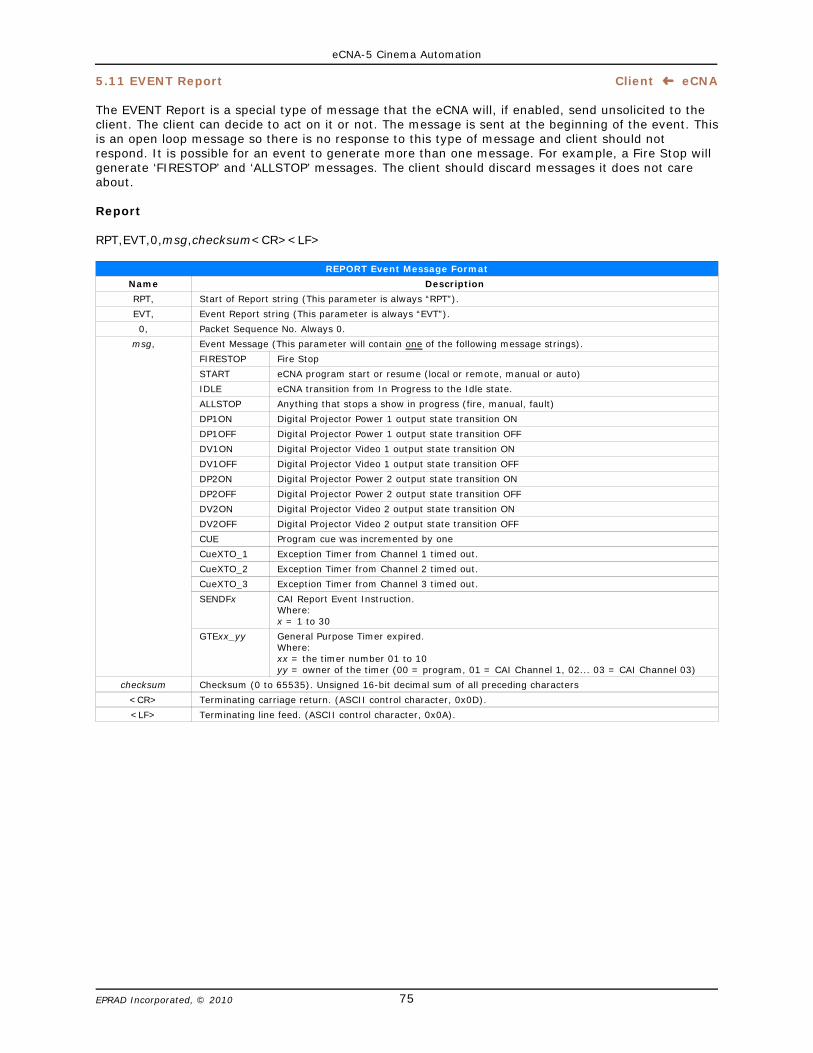
eCNA-5 Cinema Automation
75EPRAD Incorporated, © 2010
5.11 EVENT Report Client ³ eCNA
The EVENT Report is a special type of message that the eCNA will, if enabled, send unsolicited to theclient. The client can decide to act on it or not. The message is sent at the beginning of the event. Thisis an open loop message so there is no response to this type of message and client should notrespond. It is possible for an event to generate more than one message. For example, a Fire Stop willgenerate ‘FIRESTOP’ and ‘ALLSTOP’ messages. The client should discard messages it does not careabout.
Report
RPT,EVT,0,msg,checksum<CR><LF>
REPORT Event Message Format
Name Description
RPT, Start of Report string (This parameter is always “RPT”).
EVT, Event Report string (This parameter is always “EVT”).
0, Packet Sequence No. Always 0.
msg, Event Message (This parameter will contain one of the following message strings).
FIRESTOP Fire Stop
START eCNA program start or resume (local or remote, manual or auto)
IDLE eCNA transition from In Progress to the Idle state.
ALLSTOP Anything that stops a show in progress (fire, manual, fault)
DP1ON Digital Projector Power 1 output state transition ON
DP1OFF Digital Projector Power 1 output state transition OFF
DV1ON Digital Projector Video 1 output state transition ON
DV1OFF Digital Projector Video 1 output state transition OFF
DP2ON Digital Projector Power 2 output state transition ON
DP2OFF Digital Projector Power 2 output state transition OFF
DV2ON Digital Projector Video 2 output state transition ON
DV2OFF Digital Projector Video 2 output state transition OFF
CUE Program cue was incremented by one
CueXTO_1 Exception Timer from Channel 1 timed out.
CueXTO_2 Exception Timer from Channel 2 timed out.
CueXTO_3 Exception Timer from Channel 3 timed out.
SENDFx CAI Report Event Instruction.Where:x = 1 to 30
GTExx_yy General Purpose Timer expired.Where:xx = the timer number 01 to 10yy = owner of the timer (00 = program, 01 = CAI Channel 1, 02... 03 = CAI Channel 03)
checksum Checksum (0 to 65535). Unsigned 16-bit decimal sum of all preceding characters
<CR> Terminating carriage return. (ASCII control character, 0x0D).
<LF> Terminating line feed. (ASCII control character, 0x0A).
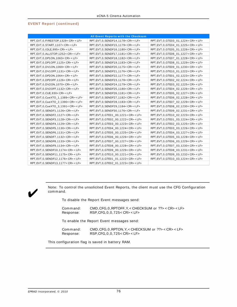
eCNA-5 Cinema Automation
76EPRAD Incorporated, © 2010
EVENT Report (continued)
All Event Reports with the Checksum
RPT,EVT,0,FIRESTOP,1329<CR><LF> RPT,EVT,0,SENDF14,1178<CR><LF> RPT,EVT,0,GTE03_01,1224<CR><LF>
RPT,EVT,0,START,1107<CR><LF> RPT,EVT,0,SENDF15,1179<CR><LF> RPT,EVT,0,GTE04_01,1225<CR><LF>
RPT,EVT,0,IDLE,995<CR><LF> RPT,EVT,0,SENDF16,1180<CR><LF> RPT,EVT,0,GTE05_01,1226<CR><LF>
RPT,EVT,0,ALLSTOP,1252<CR><LF> RPT,EVT,0,SENDF17,1181<CR><LF> RPT,EVT,0,GTE06_01,1227<CR><LF>
RPT,EVT,0,DP1ON,1063<CR><LF> RPT,EVT,0,SENDF18,1182<CR><LF> RPT,EVT,0,GTE07_01,1228<CR><LF>
RPT,EVT,0,DP1OFF,1125<CR><LF> RPT,EVT,0,SENDF19,1183<CR><LF> RPT,EVT,0,GTE08_01,1229<CR><LF>
RPT,EVT,0,DV1ON,1069<CR><LF> RPT,EVT,0,SENDF20,1175<CR><LF> RPT,EVT,0,GTE09_01,1230<CR><LF>
RPT,EVT,0,DV1OFF,1131<CR><LF> RPT,EVT,0,SENDF21,1176<CR><LF> RPT,EVT,0,GTE10_01,1222<CR><LF>
RPT,EVT,0,DP2ON,1064<CR><LF> RPT,EVT,0,SENDF22,1177<CR><LF> RPT,EVT,0,GTE01_02,1223<CR><LF>
RPT,EVT,0,DP2OFF,1126<CR><LF> RPT,EVT,0,SENDF23,1178<CR><LF> RPT,EVT,0,GTE02_02,1224<CR><LF>
RPT,EVT,0,DV2ON,1070<CR><LF> RPT,EVT,0,SENDF24,1179<CR><LF> RPT,EVT,0,GTE03_02,1225<CR><LF>
RPT,EVT,0,DV2OFF,1132<CR><LF> RPT,EVT,0,SENDF25,1180<CR><LF> RPT,EVT,0,GTE04_02,1226<CR><LF>
RPT,EVT,0,CUE,930<CR><LF> RPT,EVT,0,SENDF26,1181<CR><LF> RPT,EVT,0,GTE05_02,1227<CR><LF>
RPT,EVT,0,CueXTO_1,1389<CR><LF> RPT,EVT,0,SENDF27,1182<CR><LF> RPT,EVT,0,GTE06_02,1228<CR><LF>
RPT,EVT,0,CueXTO_2,1390<CR><LF> RPT,EVT,0,SENDF28,1183<CR><LF> RPT,EVT,0,GTE07_02,1229<CR><LF>
RPT,EVT,0,CueXTO_3,1391<CR><LF> RPT,EVT,0,SENDF29,1184<CR><LF> RPT,EVT,0,GTE08_02,1230<CR><LF>
RPT,EVT,0,SENDF1,1126<CR><LF> RPT,EVT,0,SENDF30,1176<CR><LF> RPT,EVT,0,GTE09_02,1231<CR><LF>
RPT,EVT,0,SENDF2,1127<CR><LF> RPT,EVT,0,GTE01_00,1221<CR><LF> RPT,EVT,0,GTE10_02,1223<CR><LF>
RPT,EVT,0,SENDF3,1128<CR><LF> RPT,EVT,0,GTE02_00,1222<CR><LF> RPT,EVT,0,GTE01_03,1224<CR><LF>
RPT,EVT,0,SENDF4,1129<CR><LF> RPT,EVT,0,GTE03_00,1223<CR><LF> RPT,EVT,0,GTE02_03,1225<CR><LF>
RPT,EVT,0,SENDF5,1130<CR><LF> RPT,EVT,0,GTE04_00,1224<CR><LF> RPT,EVT,0,GTE03_03,1226<CR><LF>
RPT,EVT,0,SENDF6,1131<CR><LF> RPT,EVT,0,GTE05_00,1225<CR><LF> RPT,EVT,0,GTE04_03,1227<CR><LF>
RPT,EVT,0,SENDF7,1132<CR><LF> RPT,EVT,0,GTE06_00,1226<CR><LF> RPT,EVT,0,GTE05_03,1228<CR><LF>
RPT,EVT,0,SENDF8,1133<CR><LF> RPT,EVT,0,GTE07_00,1227<CR><LF> RPT,EVT,0,GTE06_03,1229<CR><LF>
RPT,EVT,0,SENDF9,1134<CR><LF> RPT,EVT,0,GTE08_00,1228<CR><LF> RPT,EVT,0,GTE07_03,1230<CR><LF>
RPT,EVT,0,SENDF10,1174<CR><LF> RPT,EVT,0,GTE09_00,1229<CR><LF> RPT,EVT,0,GTE08_03,1231<CR><LF>
RPT,EVT,0,SENDF11,1175<CR><LF> RPT,EVT,0,GTE10_00,1221<CR><LF> RPT,EVT,0,GTE09_03,1232<CR><LF>
RPT,EVT,0,SENDF12,1176<CR><LF> RPT,EVT,0,GTE01_01,1222<CR><LF> RPT,EVT,0,GTE10_03,1224<CR><LF>
RPT,EVT,0,SENDF13,1177<CR><LF> RPT,EVT,0,GTE02_01,1223<CR><LF>
UNote: To control the unsolicited Event Reports, the client must use the CFG Configurationcommand.
To disable the Report Event messages send:
Command: CMD,CFG,0,RPTOFF,Y,<CHECKSUM or ??><CR><LF>Response: RSP,CFG,0,0,725<CR><LF>
To enable the Report Event messages send:
Command: CMD,CFG,0,RPTON,Y,<CHECKSUM or ??><CR><LF>Response: RSP,CFG,0,0,725<CR><LF>
This configuration flag is saved in battery RAM.

eCNA-5 Cinema Automation
77EPRAD Incorporated, © 2010
5.12 EVENT Log Client ³ eCNA
A history of activity is stored at the eCNA in a log file in battery-backed memory. If this feature isenabled, event records are sent one a time and at a low priority so they shouldn’t interfere with othertransactions. The client can store these records to it’s own disk file for future use. This is an open loopmessage so there is no response to this type of message and client should not respond.
Usage Note: To get the “run time” event logging, just turn logging on with the Configuration commandand leave it on. The client will get any buffered events, and then receive new events in real time asthey are buffered. This method collects logged events as they happen. To get “on-demand” eventlogging, turn logging on with the Configuration command to receive all the buffered events (since thelast time you retrieved them). Then turn logging back off with the Configuration command until thenext time you want to gather events. This method can be used to collect all the logged events at theend of a show or at the end of the day, week, etc.
Log
LOG,EVT,0,record,checksum<CR><LF>
Event Log Format
Parameter Description
LOG, Start of Log string (This parameter is always “LOG”)
EVT, Event Log string (This parameter is always “EVT”).
0, Packet Sequence No. Always 0.
record, Log Record (This parameter will contain all of the following message strings).
ID,Record,Device,Code,Code Name,Event Flags,Sequence,Year,Month,Day,Hour,Minutes,Seconds,Hundredths,Down Time,Loop,Program,Status,
Cue,P1,P2,P3,P4,P5,P6,P7,P8
Network ID (Screen Number). 1 byte decimal, 1 - 63 Event record version. 1 byte decimal, 0Type of Device. 1 byte decimal, 12 = eCNA-5Event code number. 2 bytes decimal, 0 to 65535Event code name. Text, max length = 8 characters32 bit event flags. Show sequence number. 2 byte decimal, 0 to 65535Event date stamp. Year. 2 byte decimal number.Event date stamp. Month. 1 byte decimal number, 1 to 12Event date stamp. Day. 1 byte decimal number, 1 to 31Event time stamp. Hour. 1 byte decimal number, 0 to 23Event time stamp. Minute. 1 byte decimal number, 0 to 59 Event time stamp. Second. 1 byte decimal number, 0 to 59Event time stamp. Hundredths of a second. 1 byte decimal, 0 to 99Accumulated show down timeSync loop number. 1 byte decimal, 0 to 20Program Number. 1 byte decimal, 1 to 9Show status. 1 byte decimal. 1 = Ready to Run, 2 = Fault, 3 = Running, 4 =Intermission, 5 = StoppedCue number. 1 byte decimal, 0 to 20Parameters 1. Event specific data. 2 byte decimal, 0 to 65535Parameters 2. Event specific data. 2 byte decimal, 0 to 65535Parameters 3. Event specific data. 2 byte decimal, 0 to 65535Parameters 4. Event specific data. 2 byte decimal, 0 to 65535Parameters 5. Event specific data. 2 byte decimal, 0 to 65535Parameters 6. Event specific data. 2 byte decimal, 0 to 65535Parameters 7. Event specific data. 2 byte decimal, 0 to 65535Parameters 8. Event specific data. 2 byte decimal, 0 to 65535
checksum Checksum (0 to 65535). Unsigned 16-bit decimal sum of all preceding characters
<CR> Terminating carriage return. (ASCII control character, 0x0D).
<LF> Terminating line feed. (ASCII control character, 0x0A).
Event Log Example
LOG,EVT,0,27,0,12,1,StartMan,1090584577,16,2008,6,10,7,33,21,82,0,0,1,0,0,0,0,0,0,0,0,0,0,4913

eCNA-5 Cinema Automation
78EPRAD Incorporated, © 2010
EVENT Log (continued)
UNote: To control the unsolicited Event Logs, the client must use the CFG Configurationcommand.
To disable the Log Event messages send:
Command: CMD,CFG,0,LOGOFF,Y,<CHECKSUM OR ??><CR><LF>Response: CMD,CFG,0,0,725<CR><LF>
To enable the send Logged Events send:
Command: CMD,CFG,0,LOGON,Y,<CHECKSUM or ??><CR><LF>Response: RSP,CFG,0,0,725<CR><LF>
This configuration flag is saved in battery RAM.

eCNA-5 Cinema Automation
79EPRAD Incorporated, © 2010
EVENT Log (continued)
Event Record Detail
Parameter Description
ID, This is the Screen ID. DIP switches S1-3 through S1-8 on the eCNA Main CPU are used to configure the ID number.This number should correspond with the screen number.
Record, This is the record version number.
Device, This is the Network Device Type. 12 = eCNA-5
Code, This is the event code number. Each event has a unique number.
Code Name, This is the name of the event. This is text with a maximum of 8 characters.
Event Flags,
This is a 32 bit event flag. Bit 0 is the LSB. This is a decimal number in the range 0 to 232 - 1
Bit 0Bit 1Bit 2Bit 3Bit 4Bit 5Bit 6Bit 7
------------In Progress *------------Running *------------------------------------------------
Bit 8Bit 9Bit 10Bit 11Bit 12Bit 13Bit 14Bit 15
------------------------------------------------------------------------------------------------
Bit 16Bit 17Bit 18Bit 19Bit 20Bit 21Bit 22Bit 23
Any Event **------------Ready to Resume **Ready to Run **User Code **Resume **Cue **Show End **
Bit 24Bit 25Bit 26Bit 27Bit 28Bit 29Bit 30Bit 31
Show Start **Minor Fault **------------Major Fault **Computer **Unscheduled Shutdown **Scheduled Events **Buffer Overflow - Lost Data *
The flag bits can be used to organize events for reporting purposes. These bits represent either run time ‘status’ orevent ‘type’ flags.* = Status Flags. These flags are set depending on the status of the eCNA at the time of the event.** = Type Flags. These flags are set depending on the type of event.
Sequence, This parameter is the Show sequence number. This number is incremented for each new show. This number is usedto group all events for a particular show. This is a decimal number in the range of 0 to 9999. This number can bereset (cleared) by the client.
Year, This parameter is the year value of the date stamp for the logged event. This is a two byte decimal number.
Month, This parameter is the month value of the date stamp for the logged event. This is a decimal number in the range of1 to 12.
Day, This parameter is the day value of the date stamp for the logged event. This is a decimal number in the range of 1to 31.
Hour, This parameter is the hour value of the time stamp for the logged event. This is a decimal number in the range of 0to 23.
Minutes, This parameter is the minutes value of the time stamp for the logged event. This is a decimal number in the rangeof 0 to 59.
Seconds, This parameter is the seconds value of the time stamp for the logged event. This is a decimal number in the rangeof 0 to 59.
Hundredths, This parameter is the hundredths of a second value of the time stamp for the logged event. This is a decimalnumber in the range of 0 to 99.
Down Time, This is an accumulated time value that is the unscheduled show down time. This is a decimal number thatrepresents the down time in seconds.
Loop, Sync Loop Number. This is a decimal number in the range of 1 to 20.
Program, Program Number. This is a decimal number in the range of 1 to 20.
Status, This is the Show Status at the time of the event. 0 = Ready to Run, 1 = Fault, 2 = Running, 3 = Intermission, 4 =Stopped
Cue, This is the Cue Number at the time of the event.
P1, Parameter 1 - Event specific data.
P2, Parameter 2 - Event specific data.
P3, Parameter 3 - Event specific data.
P4, Parameter 4 - Event specific data.
P5, Parameter 5 - Event specific data.
P6, Parameter 6 - Event specific data.
P7, Parameter 7 - Event specific data.
P8, Parameter 8 - Event specific data.
The client can use some or all of these parameters to generate Event Log or Show Log reports. Usingthe Event flags can simplify organizing the events.
Using Hyperterminal or another terminal software program, the events can easily be captured to atext file and imported into a spreadsheet for examination.
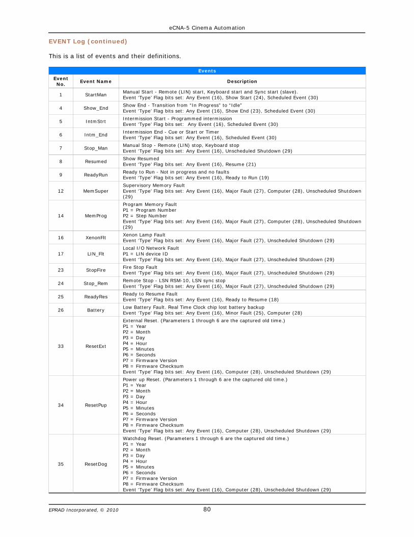
eCNA-5 Cinema Automation
80EPRAD Incorporated, © 2010
EVENT Log (continued)
This is a list of events and their definitions.
Events
EventNo. Event Name Description
1 StartMan Manual Start - Remote (LIN) start, Keyboard start and Sync start (slave). Event ‘Type’ Flag bits set: Any Event (16), Show Start (24), Scheduled Event (30)
4 Show_End Show End - Transition from “In Progress” to “Idle”Event ‘Type’ Flag bits set: Any Event (16), Show End (23), Scheduled Event (30)
5 IntmStrtIntermission Start - Programmed intermissionEvent ‘Type’ Flag bits set: Any Event (16), Scheduled Event (30)
6 Intm_EndIntermission End - Cue or Start or TimerEvent ‘Type’ Flag bits set: Any Event (16), Scheduled Event (30)
7 Stop_Man Manual Stop - Remote (LIN) stop, Keyboard stopEvent ‘Type’ Flag bits set: Any Event (16), Unscheduled Shutdown (29)
8 Resumed Show ResumedEvent ‘Type’ Flag bits set: Any Event (16), Resume (21)
9 ReadyRunReady to Run - Not in progress and no faultsEvent ‘Type’ Flag bits set: Any Event (16), Ready to Run (19)
12 MemSuperSupervisory Memory FaultEvent ‘Type’ Flag bits set: Any Event (16), Major Fault (27), Computer (28), Unscheduled Shutdown(29)
14 MemProg
Program Memory Fault P1 = Program NumberP2 = Step NumberEvent ‘Type’ Flag bits set: Any Event (16), Major Fault (27), Computer (28), Unscheduled Shutdown(29)
16 XenonFlt Xenon Lamp FaultEvent ‘Type’ Flag bits set: Any Event (16), Major Fault (27), Unscheduled Shutdown (29)
17 LIN_FltLocal I/O Network FaultP1 = LIN device IDEvent ‘Type’ Flag bits set: Any Event (16), Major Fault (27), Unscheduled Shutdown (29)
23 StopFire Fire Stop FaultEvent ‘Type’ Flag bits set: Any Event (16), Major Fault (27), Unscheduled Shutdown (29)
24 Stop_Rem Remote Stop - LSN RSM-10, LSN sync stopEvent ‘Type’ Flag bits set: Any Event (16), Major Fault (27), Unscheduled Shutdown (29)
25 ReadyRes Ready to Resume FaultEvent ‘Type’ Flag bits set: Any Event (16), Ready to Resume (18)
26 Battery Low Battery Fault. Real Time Clock chip lost battery backupEvent ‘Type’ Flag bits set: Any Event (16), Minor Fault (25), Computer (28)
33 ResetExt
External Reset. (Parameters 1 through 6 are the captured old time.)P1 = YearP2 = MonthP3 = DayP4 = HourP5 = MinutesP6 = SecondsP7 = Firmware VersionP8 = Firmware ChecksumEvent ‘Type’ Flag bits set: Any Event (16), Computer (28), Unscheduled Shutdown (29)
34 ResetPup
Power up Reset. (Parameters 1 through 6 are the captured old time.)P1 = YearP2 = MonthP3 = DayP4 = HourP5 = MinutesP6 = SecondsP7 = Firmware VersionP8 = Firmware ChecksumEvent ‘Type’ Flag bits set: Any Event (16), Computer (28), Unscheduled Shutdown (29)
35 ResetDog
Watchdog Reset. (Parameters 1 through 6 are the captured old time.)P1 = YearP2 = MonthP3 = DayP4 = HourP5 = MinutesP6 = SecondsP7 = Firmware VersionP8 = Firmware ChecksumEvent ‘Type’ Flag bits set: Any Event (16), Computer (28), Unscheduled Shutdown (29)
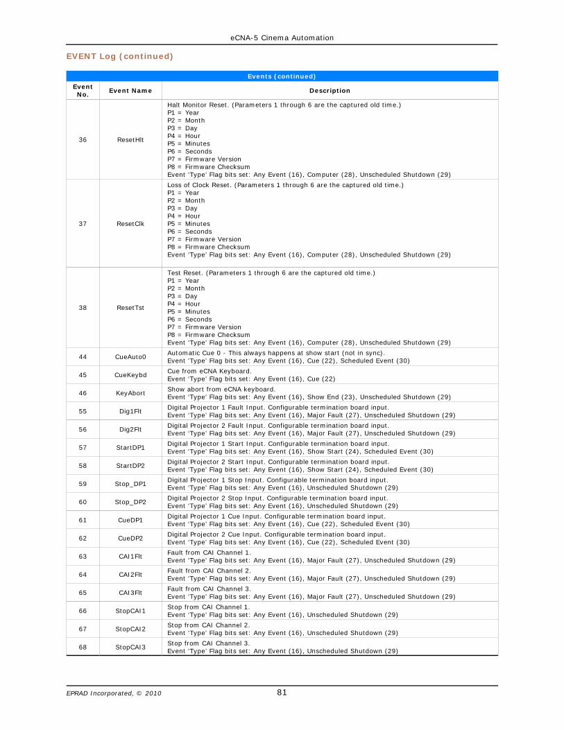
eCNA-5 Cinema Automation
81EPRAD Incorporated, © 2010
EVENT Log (continued)
Events (continued)
EventNo. Event Name Description
36 ResetHlt
Halt Monitor Reset. (Parameters 1 through 6 are the captured old time.)P1 = YearP2 = MonthP3 = DayP4 = HourP5 = MinutesP6 = SecondsP7 = Firmware VersionP8 = Firmware ChecksumEvent ‘Type’ Flag bits set: Any Event (16), Computer (28), Unscheduled Shutdown (29)
37 ResetClk
Loss of Clock Reset. (Parameters 1 through 6 are the captured old time.)P1 = YearP2 = MonthP3 = DayP4 = HourP5 = MinutesP6 = SecondsP7 = Firmware VersionP8 = Firmware ChecksumEvent ‘Type’ Flag bits set: Any Event (16), Computer (28), Unscheduled Shutdown (29)
38 ResetTst
Test Reset. (Parameters 1 through 6 are the captured old time.)P1 = YearP2 = MonthP3 = DayP4 = HourP5 = MinutesP6 = SecondsP7 = Firmware VersionP8 = Firmware ChecksumEvent ‘Type’ Flag bits set: Any Event (16), Computer (28), Unscheduled Shutdown (29)
44 CueAuto0 Automatic Cue 0 - This always happens at show start (not in sync).Event ‘Type’ Flag bits set: Any Event (16), Cue (22), Scheduled Event (30)
45 CueKeybd Cue from eCNA Keyboard.Event ‘Type’ Flag bits set: Any Event (16), Cue (22)
46 KeyAbort Show abort from eCNA keyboard.Event ‘Type’ Flag bits set: Any Event (16), Show End (23), Unscheduled Shutdown (29)
55 Dig1Flt Digital Projector 1 Fault Input. Configurable termination board input.Event ‘Type’ Flag bits set: Any Event (16), Major Fault (27), Unscheduled Shutdown (29)
56 Dig2Flt Digital Projector 2 Fault Input. Configurable termination board input.Event ‘Type’ Flag bits set: Any Event (16), Major Fault (27), Unscheduled Shutdown (29)
57 StartDP1 Digital Projector 1 Start Input. Configurable termination board input.Event ‘Type’ Flag bits set: Any Event (16), Show Start (24), Scheduled Event (30)
58 StartDP2 Digital Projector 2 Start Input. Configurable termination board input.Event ‘Type’ Flag bits set: Any Event (16), Show Start (24), Scheduled Event (30)
59 Stop_DP1 Digital Projector 1 Stop Input. Configurable termination board input.Event ‘Type’ Flag bits set: Any Event (16), Unscheduled Shutdown (29)
60 Stop_DP2 Digital Projector 2 Stop Input. Configurable termination board input.Event ‘Type’ Flag bits set: Any Event (16), Unscheduled Shutdown (29)
61 CueDP1 Digital Projector 1 Cue Input. Configurable termination board input.Event ‘Type’ Flag bits set: Any Event (16), Cue (22), Scheduled Event (30)
62 CueDP2 Digital Projector 2 Cue Input. Configurable termination board input.Event ‘Type’ Flag bits set: Any Event (16), Cue (22), Scheduled Event (30)
63 CAI1Flt Fault from CAI Channel 1.Event ‘Type’ Flag bits set: Any Event (16), Major Fault (27), Unscheduled Shutdown (29)
64 CAI2Flt Fault from CAI Channel 2.Event ‘Type’ Flag bits set: Any Event (16), Major Fault (27), Unscheduled Shutdown (29)
65 CAI3Flt Fault from CAI Channel 3.Event ‘Type’ Flag bits set: Any Event (16), Major Fault (27), Unscheduled Shutdown (29)
66 StopCAI1 Stop from CAI Channel 1.Event ‘Type’ Flag bits set: Any Event (16), Unscheduled Shutdown (29)
67 StopCAI2 Stop from CAI Channel 2.Event ‘Type’ Flag bits set: Any Event (16), Unscheduled Shutdown (29)
68 StopCAI3 Stop from CAI Channel 3.Event ‘Type’ Flag bits set: Any Event (16), Unscheduled Shutdown (29)
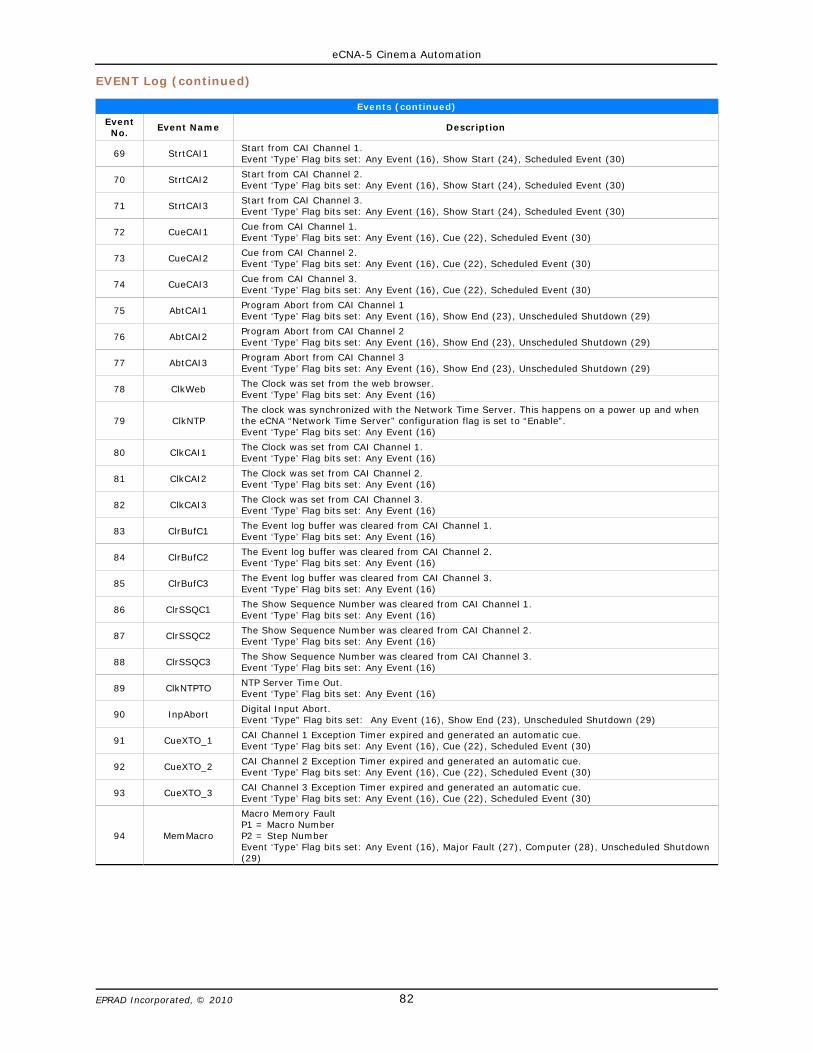
eCNA-5 Cinema Automation
82EPRAD Incorporated, © 2010
EVENT Log (continued)
Events (continued)
EventNo. Event Name Description
69 StrtCAI1 Start from CAI Channel 1.Event ‘Type’ Flag bits set: Any Event (16), Show Start (24), Scheduled Event (30)
70 StrtCAI2 Start from CAI Channel 2.Event ‘Type’ Flag bits set: Any Event (16), Show Start (24), Scheduled Event (30)
71 StrtCAI3Start from CAI Channel 3.Event ‘Type’ Flag bits set: Any Event (16), Show Start (24), Scheduled Event (30)
72 CueCAI1Cue from CAI Channel 1.Event ‘Type’ Flag bits set: Any Event (16), Cue (22), Scheduled Event (30)
73 CueCAI2 Cue from CAI Channel 2.Event ‘Type’ Flag bits set: Any Event (16), Cue (22), Scheduled Event (30)
74 CueCAI3 Cue from CAI Channel 3.Event ‘Type’ Flag bits set: Any Event (16), Cue (22), Scheduled Event (30)
75 AbtCAI1 Program Abort from CAI Channel 1Event ‘Type’ Flag bits set: Any Event (16), Show End (23), Unscheduled Shutdown (29)
76 AbtCAI2Program Abort from CAI Channel 2Event ‘Type’ Flag bits set: Any Event (16), Show End (23), Unscheduled Shutdown (29)
77 AbtCAI3 Program Abort from CAI Channel 3Event ‘Type’ Flag bits set: Any Event (16), Show End (23), Unscheduled Shutdown (29)
78 ClkWeb The Clock was set from the web browser.Event ‘Type’ Flag bits set: Any Event (16)
79 ClkNTPThe clock was synchronized with the Network Time Server. This happens on a power up and whenthe eCNA “Network Time Server” configuration flag is set to “Enable”.Event ‘Type’ Flag bits set: Any Event (16)
80 ClkCAI1 The Clock was set from CAI Channel 1.Event ‘Type’ Flag bits set: Any Event (16)
81 ClkCAI2 The Clock was set from CAI Channel 2.Event ‘Type’ Flag bits set: Any Event (16)
82 ClkCAI3 The Clock was set from CAI Channel 3.Event ‘Type’ Flag bits set: Any Event (16)
83 ClrBufC1 The Event log buffer was cleared from CAI Channel 1.Event ‘Type’ Flag bits set: Any Event (16)
84 ClrBufC2 The Event log buffer was cleared from CAI Channel 2.Event ‘Type’ Flag bits set: Any Event (16)
85 ClrBufC3 The Event log buffer was cleared from CAI Channel 3.Event ‘Type’ Flag bits set: Any Event (16)
86 ClrSSQC1 The Show Sequence Number was cleared from CAI Channel 1.Event ‘Type’ Flag bits set: Any Event (16)
87 ClrSSQC2 The Show Sequence Number was cleared from CAI Channel 2.Event ‘Type’ Flag bits set: Any Event (16)
88 ClrSSQC3 The Show Sequence Number was cleared from CAI Channel 3.Event ‘Type’ Flag bits set: Any Event (16)
89 ClkNTPTO NTP Server Time Out.Event ‘Type’ Flag bits set: Any Event (16)
90 InpAbort Digital Input Abort.Event ‘Type” Flag bits set: Any Event (16), Show End (23), Unscheduled Shutdown (29)
91 CueXTO_1 CAI Channel 1 Exception Timer expired and generated an automatic cue.Event ‘Type’ Flag bits set: Any Event (16), Cue (22), Scheduled Event (30)
92 CueXTO_2 CAI Channel 2 Exception Timer expired and generated an automatic cue.Event ‘Type’ Flag bits set: Any Event (16), Cue (22), Scheduled Event (30)
93 CueXTO_3 CAI Channel 3 Exception Timer expired and generated an automatic cue.Event ‘Type’ Flag bits set: Any Event (16), Cue (22), Scheduled Event (30)
94 MemMacro
Macro Memory Fault P1 = Macro NumberP2 = Step NumberEvent ‘Type’ Flag bits set: Any Event (16), Major Fault (27), Computer (28), Unscheduled Shutdown(29)
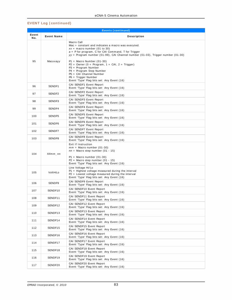
eCNA-5 Cinema Automation
83EPRAD Incorporated, © 2010
EVENT Log (continued)
Events (continued)
EventNo. Event Name Description
95 Macxxayy
Macro CallMac = constant and indicates a macro was executed.xx = macro number (01 to 30)a = P for program, C for CAI Command, T for Trigger yy = Program number (01-99), CAI Channel number (01-03), Trigger number (01-30)
P1 = Macro Number (01-30)P2 = Owner (0 = Program, 1 = CAI, 2 = Trigger)P3 = Program NumberP4 = Program Step NumberP5 = CAI Channel NumberP6 = Trigger NumberEvent ‘Type’ Flag bits set: Any Event (16)
96 SENDF1 CAI SENDF1 Event ReportEvent ‘Type’ Flag bits set: Any Event (16)
97 SENDF2CAI SENDF2 Event ReportEvent ‘Type’ Flag bits set: Any Event (16)
98 SENDF3CAI SENDF3 Event ReportEvent ‘Type’ Flag bits set: Any Event (16)
99 SENDF4 CAI SENDF4 Event ReportEvent ‘Type’ Flag bits set: Any Event (16)
100 SENDF5 CAI SENDF5 Event ReportEvent ‘Type’ Flag bits set: Any Event (16)
101 SENDF6 CAI SENDF6 Event ReportEvent ‘Type’ Flag bits set: Any Event (16)
102 SENDF7 CAI SENDF7 Event ReportEvent ‘Type’ Flag bits set: Any Event (16)
103 SENDF8 CAI SENDF8 Event ReportEvent ‘Type’ Flag bits set: Any Event (16)
104 Xifmm_nn
Exit If Instructionmm = Macro number (01-30)nn = Macro step number (01 - 15)
P1 = Macro number (01-30)P2 = Macro step number (01 - 15)Event ‘Type’ Flag bits set: Any Event (16)
105 VoltHiLo
Line Voltage Hi/Lo P1 = Highest voltage measured during the intervalP2 = Lowest voltage measured during the intervalEvent ‘Type’ Flag bits set: Any Event (16)
106 SENDF9 CAI SENDF9 Event ReportEvent ‘Type’ Flag bits set: Any Event (16)
107 SENDF10 CAI SENDF10 Event ReportEvent ‘Type’ Flag bits set: Any Event (16)
108 SENDF11 CAI SENDF11 Event ReportEvent ‘Type’ Flag bits set: Any Event (16)
109 SENDF12 CAI SENDF12 Event ReportEvent ‘Type’ Flag bits set: Any Event (16)
110 SENDF13 CAI SENDF13 Event ReportEvent ‘Type’ Flag bits set: Any Event (16)
111 SENDF14 CAI SENDF14 Event ReportEvent ‘Type’ Flag bits set: Any Event (16)
112 SENDF15 CAI SENDF15 Event ReportEvent ‘Type’ Flag bits set: Any Event (16)
113 SENDF16 CAI SENDF16 Event ReportEvent ‘Type’ Flag bits set: Any Event (16)
114 SENDF17 CAI SENDF17 Event ReportEvent ‘Type’ Flag bits set: Any Event (16)
115 SENDF18 CAI SENDF18 Event ReportEvent ‘Type’ Flag bits set: Any Event (16)
116 SENDF19 CAI SENDF19 Event ReportEvent ‘Type’ Flag bits set: Any Event (16)
117 SENDF20 CAI SENDF20 Event ReportEvent ‘Type’ Flag bits set: Any Event (16)

eCNA-5 Cinema Automation
84EPRAD Incorporated, © 2010
EVENT Log (continued)
Events (continued)
EventNo. Event Name Description
118 SENDF21 CAI SENDF21 Event ReportEvent ‘Type’ Flag bits set: Any Event (16)
119 SENDF22 CAI SENDF22 Event ReportEvent ‘Type’ Flag bits set: Any Event (16)
120 SENDF23CAI SENDF23 Event ReportEvent ‘Type’ Flag bits set: Any Event (16)
121 SENDF24CAI SENDF24 Event ReportEvent ‘Type’ Flag bits set: Any Event (16)
122 SENDF25 CAI SENDF25 Event ReportEvent ‘Type’ Flag bits set: Any Event (16)
123 SENDF26 CAI SENDF26 Event ReportEvent ‘Type’ Flag bits set: Any Event (16)
124 SENDF27 CAI SENDF27 Event ReportEvent ‘Type’ Flag bits set: Any Event (16)
125 SENDF28CAI SENDF28 Event ReportEvent ‘Type’ Flag bits set: Any Event (16)
126 SENDF29 CAI SENDF29 Event ReportEvent ‘Type’ Flag bits set: Any Event (16)
127 SENDF30 CAI SENDF30 Event ReportEvent ‘Type’ Flag bits set: Any Event (16)
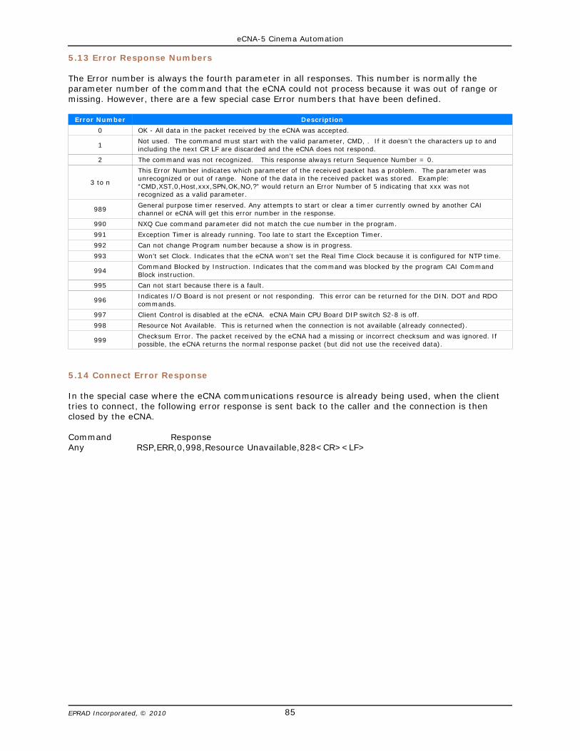
eCNA-5 Cinema Automation
85EPRAD Incorporated, © 2010
5.13 Error Response Numbers
The Error number is always the fourth parameter in all responses. This number is normally theparameter number of the command that the eCNA could not process because it was out of range ormissing. However, there are a few special case Error numbers that have been defined.
Error Number Description
0 OK - All data in the packet received by the eCNA was accepted.
1Not used. The command must start with the valid parameter, CMD, . If it doesn’t the characters up to andincluding the next CR LF are discarded and the eCNA does not respond.
2 The command was not recognized. This response always return Sequence Number = 0.
3 to n
This Error Number indicates which parameter of the received packet has a problem. The parameter wasunrecognized or out of range. None of the data in the received packet was stored. Example:“CMD,XST,0,Host,xxx,SPN,OK,NO,?” would return an Error Number of 5 indicating that xxx was notrecognized as a valid parameter.
989 General purpose timer reserved. Any attempts to start or clear a timer currently owned by another CAIchannel or eCNA will get this error number in the response.
990 NXQ Cue command parameter did not match the cue number in the program.
991 Exception Timer is already running. Too late to start the Exception Timer.
992 Can not change Program number because a show is in progress.
993 Won’t set Clock. Indicates that the eCNA won’t set the Real Time Clock because it is configured for NTP time.
994 Command Blocked by Instruction. Indicates that the command was blocked by the program CAI CommandBlock instruction.
995 Can not start because there is a fault.
996 Indicates I/O Board is not present or not responding. This error can be returned for the DIN. DOT and RDOcommands.
997 Client Control is disabled at the eCNA. eCNA Main CPU Board DIP switch S2-8 is off.
998 Resource Not Available. This is returned when the connection is not available (already connected).
999 Checksum Error. The packet received by the eCNA had a missing or incorrect checksum and was ignored. Ifpossible, the eCNA returns the normal response packet (but did not use the received data).
5.14 Connect Error Response
In the special case where the eCNA communications resource is already being used, when the clienttries to connect, the following error response is sent back to the caller and the connection is thenclosed by the eCNA.
Command ResponseAny RSP,ERR,0,998,Resource Unavailable,828<CR><LF>
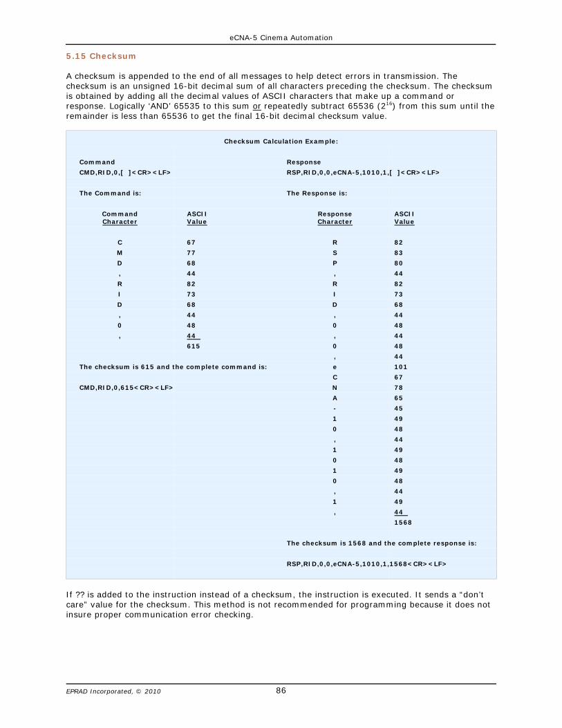
eCNA-5 Cinema Automation
86EPRAD Incorporated, © 2010
5.15 Checksum
A checksum is appended to the end of all messages to help detect errors in transmission. Thechecksum is an unsigned 16-bit decimal sum of all characters preceding the checksum. The checksumis obtained by adding all the decimal values of ASCII characters that make up a command orresponse. Logically ‘AND’ 65535 to this sum or repeatedly subtract 65536 (216) from this sum until theremainder is less than 65536 to get the final 16-bit decimal checksum value.
Checksum Calculation Example:
Command Response
CMD,RID,0,[ ]<CR><LF> RSP,RID,0,0,eCNA-5,1010,1,[ ]<CR><LF>
The Command is: The Response is:
CommandCharacter
ASCIIValue
ResponseCharacter
ASCIIValue
C 67 R 82
M 77 S 83
D 68 P 80
, 44 , 44
R 82 R 82
I 73 I 73
D 68 D 68
, 44 , 44
0 48 0 48
, 44 , 44
615 0 48
, 44
The checksum is 615 and the complete command is: e 101
C 67
CMD,RID,0,615<CR><LF> N 78
A 65
- 45
1 49
0 48
, 44
1 49
0 48
1 49
0 48
, 44
1 49
, 44
1568
The checksum is 1568 and the complete response is:
RSP,RID,0,0,eCNA-5,1010,1,1568<CR><LF>
If ?? is added to the instruction instead of a checksum, the instruction is executed. It sends a “don’tcare” value for the checksum. This method is not recommended for programming because it does notinsure proper communication error checking.

eCNA-5 Cinema Automation
87EPRAD Incorporated, © 2010
5.16 Command Summary
All Commands and Responses end with a checksum, carriage return and line feed. Checksum = 0 to 65535. Carriage Return = 0Dh. Line Feed = 0Ah.
FUNCTION
COMMAND RESPONSE
REF.ASCIICommand
Code
ASCIIFunction
Code
PacketSequenceNumber
ASCIIParameters
RequestAck
ASCIIResponse
Code
ASCIIFunction
Code
PacketSequenceNumber
ErrorNumber
ASCIIParameters
Read Clock CMD, RCK, 0-65535, RSP, RCK, 0-65535, 0-999, yyyy,mm,dd,hh,mm,ss,ttt,
Set Clock CMD, SCK, 0-65535, yyyy,mm,dd,hh,mm,ss,ttt, RSP, SCK, 0-65535, 0-999,
Get Control StateStatus
CMD, STS, 0-65535, CTRLST, RSP, STS, 0-65535, 0-999, IDL, | RUN,
Get Cue Number CMD, STS, 0-65535, CUENO, RSP, STS, 0-65535, 0-999, 0 - 20,
Get Stopped StateStatus
CMD, STS, 0-65535, STPST, RSP, STS, 0-65535, 0-999, OK, | STP, | FLT, | FIR,
Get Digital 1 Power Control Flag Status
CMD, STS, 0-65535, DP1CF, RSP, STS, 0-65535, 0-999, NO, | D1P,
Get Digital 1 Power Output Status Flag
CMD, STS, 0-65535, DP1OS, RSP, STS, 0-65535, 0-999, NO, | D1P,
Get Digital 1 Video Control Flag
CMD, STS, 0-65535, DV1CF, RSP, STS, 0-65535, 0-999, NO, | D1V,
Get Digital 1 VideoOutput Status Flag
CMD, STS, 0-65535, DV1OS, RSP, STS, 0-65535, 0-999, NO, | D1V,
Get Digital 2 Power Control Flag
CMD, STS, 0-65535, DP2CF, RSP, STS, 0-65535, 0-999, NO, | D2P,
Get Digital 2 PowerOutput Status Flag
CMD, STS, 0-65535, DP2OS, RSP, STS, 0-65535, 0-999, NO, | D2P,
Get Digital 2 VideoControl Flag
CMD, STS, 0-65535, DV2CF, RSP, STS, 0-65535, 0-999, NO, | D2V,
Get Digital 2 VideoOutput Status
CMD, STS, 0-65535, DV2OS, RSP, STS, 0-65535, 0-999, NO, | D2V,
Get Film ProjectorOutput Status
CMD, STS, 0-65535, FPOS, RSP, STS, 0-65535, 0-999, NO, | PJM,
Get Film Changeover DouserOutput Status
CMD, STS, 0-65535, FCOOS, RSP, STS, 0-65535, 0-999, NO, | C/O,
Get Slide (Aux) ProjectorControl Flag
CMD, STS, 0-65535, SPCF, RSP, STS, 0-65535, 0-999, NO, | AUX,
Get Slide (Aux) ProjectorOutput Status
CMD, STS, 0-65535, SPOS, RSP, STS, 0-65535, 0-999, NO, | AUX,
Get Sync Mode Status CMD, STS, 0-65535, SYNC, RSP, STS, 0-65535, 0-999, NO, | YES,
Get CPU Reset Status CMD, STS, 0-65535, RESET, RSP, STS, 0-65535, 0-999, 0 - 255,
Get Segment Index Number CMD, STS, 0-65535, SEGIDX, RSP, STS, 0-65535, 0-999, 0 - 9,
Get Segment Name CMD, STS, 0-65535, SEGTXT, RSP, STS, 0-65535, 0-999, a,
Get CAI Command AccessFlag
CMD, STS, 0-65535, CAICMD, RSP, STS, 0-65535, 0-999, OK, | BLK,
Get Program Number CMD, STS, 0-65535, PROGN, RSP, STS, 0-65535, 0-999, 0 - 9,
Get Exception Timer Status CMD, STS, 0-65535, XTMR, RSP, STS, 0-65535, 0-999, n,d,m,s,
Get Wait Event InstructionStatus
CMD, STS, 0-65535, WAITEV, RSP, STS, 0-65535, 0-999, n,s,
Get GP Timer Status CMD, STS, 0-65535, GTMR,n, RSP, STS, 0-65535, 0-999, n,e,s,mm,ss,
Exchange Status CMD, XST, 0-65535, < client status record>, RSP, XST, 0-65535, 0-999, <eCNA status record>,
Report Status CMD, RST, 0-65535, RSP, RST, 0-65535, 0-999, <eCNA status record>,
Report Id CMD, RID, 0-65535, RSP, RID, 0-65535, 0-999, n,v,s,
Start Program CMD, EVT, 0-65535, STA, Y/N RSP, EVT, 0-65535, 0-999,
Stop Program CMD, EVT, 0-65535, STP, Y/N RSP, EVT, 0-65535, 0-999,
Fault CMD, EVT, 0-65535, FLT, Y/N RSP, EVT, 0-65535, 0-999,
Cue Program CMD, EVT, 0-65535, CUE, Y/N RSP, EVT, 0-65535, 0-999,
Clear Fault CMD, EVT, 0-65535, FLT, Y/N RSP, EVT, 0-65535, 0-999,
Abort Program CMD, EVT, 0-65535, ABT Y/N RSP, EVT, 0-65535, 0-999,
Cancel Alarm CMD, EVT, 0-65535, CNL, Y/N RSP, EVT, 0-65535, 0-999,
Reset Fault CMD, EVT, 0-65535, RES, Y/N RSP, EVT, 0-65535, 0-999,
Set Program Number CMD, EVT, 0-65535, PGM,d, Y/N RSP, EVT, 0-65535, 0-999,
Start Exception Timer CMD, EVT, 0-65535, SXT,d,m,s, Y/N RSP, EVT, 0-65535, 0-999,
Cue Program CMD, EVT, 0-65535, NXQ,d, Y/N RSP, EVT, 0-65535, 0-999,
Block Commands CMD, EVT, 0-65535, CAI,d,m, Y/N RSP, EVT, 0-65535, 0-999,
Start Macro CMD, EVT, 0-65535, MAC,n Y/N RSP, EVT, 0-65535, 0-999,
Set/Clear GP Timer CMD, EVT, 0-65535, SGT,n,m,s, Y/N RSP, EVT, 0-65535, 0-999,
Get All Event Logs CMD, LOG, 0-65535, GETALL, Y/N RSP, LOG, 0-65535, 0-999, <all event logs>
Clear Log Buffer CMD, LOG, 0-65535, CLRBUF, Y/N RSP, LOG, 0-65535, 0-999,
Clear Log Show Number CMD, LOG, 0-65535, CLRSSQ, Y/N RSP, LOG, 0-65535, 0-999,
Enable Event Report CMD, CFG, 0-65535, RPTON, Y/N RSP, CFG, 0-65535, 0-999,
Disable Event Report CMD, CFG, 0-65535, RPTOFF, Y/N RSP, CFG, 0-65535, 0-999,
Enable Event Log CMD, CFG, 0-65535, LOGON, Y/N RSP, CFG, 0-65535, 0-999,
Disable Event Log CMD, CFG, 0-65535, LOGOFF, Y/N RSP, CFG, 0-65535, 0-999,
Enable Macro Calls Logging CMD, CFG, 0-65535, OPT1ON, Y/N RSP, CFG, 0-65535, 0-999,
Disable Macro Calls Logging CMD, CFG, 0-65535, OPT1OFF, Y/N RSP, CFG, 0-65535, 0-999,

eCNA-5 Cinema Automation
88EPRAD Incorporated, © 2010
Command Summary (continued)
FUNCTION
COMMAND RESPONSE
REF.ASCIICommand
Code
ASCIIFunction
Code
PacketSequenceNumber
ASCIIParameters
RequestAck
ASCIIResponse
Code
ASCIIFunction
Code
PacketSequenceNumber
ErrorNumber
ASCIIParameters
Lights: House Up CMD, OUT, 0-65535, HLUP, Y/N RSP, OUT, 0-65535, 0-999,
Lights: House Mid 1 CMD, OUT, 0-65535, HLMID1, Y/N RSP, OUT, 0-65535, 0-999,
Lights: House Mid 2 CMD, OUT, 0-65535, HLMID2, Y/N RSP, OUT, 0-65535, 0-999,
Lights: House Down CMD, OUT, 0-65535, HLDOWN, Y/N RSP, OUT, 0-65535, 0-999,
Lights: Stage Up CMD, OUT, 0-65535, SLUP, Y/N RSP, OUT, 0-65535, 0-999,
Lights: Stage Down CMD, OUT, 0-65535, SLDOWN, Y/N RSP, OUT, 0-65535, 0-999,
Curtain Open: CMD, OUT, 0-65535, CURTOPEN, Y/N RSP, OUT, 0-65535, 0-999,
Curtain Close: CMD, OUT, 0-65535, CURTCLOS, Y/N RSP, OUT, 0-65535, 0-999,
Masking: Flat CMD, OUT, 0-65535, MSKFLAT, Y/N RSP, OUT, 0-65535, 0-999,
Masking: Scope CMD, OUT, 0-65535, MSKSCOPE, Y/N RSP, OUT, 0-65535, 0-999,
Masking: Special CMD, OUT, 0-65535, MSKSPECL, Y/N RSP, OUT, 0-65535, 0-999,
Lens: Flat CMD, OUT, 0-65535, LENSFLAT, Y/N RSP, OUT, 0-65535, 0-999,
Lens: Scope CMD, OUT, 0-65535, LENSCOPE, Y/N RSP, OUT, 0-65535, 0-999,
Lens: Special CMD, OUT, 0-65535, LENSPECL, Y/N RSP, OUT, 0-65535, 0-999,
Sound: Aux 1 CMD, OUT, 0-65535, SNDAUX1, Y/N RSP, OUT, 0-65535, 0-999,
Sound: Aux 2 CMD, OUT, 0-65535, SNDAUX2, Y/N RSP, OUT, 0-65535, 0-999,
Sound: Digital 1 CMD, OUT, 0-65535, SNDDIG1, Y/N RSP, OUT, 0-65535, 0-999,
Sound: Digital 2 CMD, OUT, 0-65535, SNDDIG2, Y/N RSP, OUT, 0-65535, 0-999,
Sound: Mono CMD, OUT, 0-65535, SNDMONO, Y/N RSP, OUT, 0-65535, 0-999,
Sound: Mute On CMD, OUT, 0-65535, MUTEON, Y/N RSP, OUT, 0-65535, 0-999,
Sound: Mute Off CMD, OUT, 0-65535, MUTEOFF, Y/N RSP, OUT, 0-65535, 0-999,
Sound: Non-Sync CMD, OUT, 0-65535, SNDNSYNC, Y/N RSP, OUT, 0-65535, 0-999,
Sound: SR CMD, OUT, 0-65535, SNDSR, Y/N RSP, OUT, 0-65535, 0-999,
Sound: SVA CMD, OUT, 0-65535, SNDSVA, Y/N RSP, OUT, 0-65535, 0-999,
Aux Out 1: On CMD, OUT, 0-65535, OUT1ON, Y/N RSP, OUT, 0-65535, 0-999,
Aux Out 1: Off CMD, OUT, 0-65535, OUT1OFF, Y/N RSP, OUT, 0-65535, 0-999,
Aux Out 2: On CMD, OUT, 0-65535, OUT2ON, Y/N RSP, OUT, 0-65535, 0-999,
Aux Out 2: Off CMD, OUT, 0-65535, OUT2OFF, Y/N RSP, OUT, 0-65535, 0-999,
Aux Out 3: On CMD, OUT, 0-65535, OUT3ON, Y/N RSP, OUT, 0-65535, 0-999,
Aux Out 3: Off CMD, OUT, 0-65535, OUT3OFF, Y/N RSP, OUT, 0-65535, 0-999,
Aux Out 4: On CMD, OUT, 0-65535, OUT4ON, Y/N RSP, OUT, 0-65535, 0-999,
Aux Out 4: Off CMD, OUT, 0-65535, OUT4OFF, Y/N RSP, OUT, 0-65535, 0-999,
Aux Out 5: On CMD, OUT, 0-65535, OUT5ON, Y/N RSP, OUT, 0-65535, 0-999,
Aux Out 5: Off CMD, OUT, 0-65535, OUT5OFF, Y/N RSP, OUT, 0-65535, 0-999,
Aux Out 6: On CMD, OUT, 0-65535, OUT6ON, Y/N RSP, OUT, 0-65535, 0-999,
Aux Out 6: Off CMD, OUT, 0-65535, OUT6OFF, Y/N RSP, OUT, 0-65535, 0-999,
Aux Out 7: On CMD, OUT, 0-65535, OUT7ON, Y/N RSP, OUT, 0-65535, 0-999,
Aux Out 7: Off CMD, OUT, 0-65535, OUT7OFF, Y/N RSP, OUT, 0-65535, 0-999,
Aux Out 8: On CMD, OUT, 0-65535, OUT8ON, Y/N RSP, OUT, 0-65535, 0-999,
Aux Out 8: Off CMD, OUT, 0-65535, OUT8OFF, Y/N RSP, OUT, 0-65535, 0-999,
Aux Out 9: On CMD, OUT, 0-65535, OUT9ON, Y/N RSP, OUT, 0-65535, 0-999,
Aux Out 9: Off CMD, OUT, 0-65535, OUT9OFF, Y/N RSP, OUT, 0-65535, 0-999,
Aux Out 10: On CMD, OUT, 0-65535, OUT10ON, Y/N RSP, OUT, 0-65535, 0-999,
Aux Out 10: Off CMD, OUT, 0-65535, OUT10OFF, Y/N RSP, OUT, 0-65535, 0-999,
Aux Out 11: On CMD, OUT, 0-65535, OUT11ON, Y/N RSP, OUT, 0-65535, 0-999,
Aux Out 11: Off CMD, OUT, 0-65535, OUT11OFF, Y/N RSP, OUT, 0-65535, 0-999,
Aux Out 12: On CMD, OUT, 0-65535, OUT12ON, Y/N RSP, OUT, 0-65535, 0-999,
Aux Out 12: Off CMD, OUT, 0-65535, OUT12OFF, Y/N RSP, OUT, 0-65535, 0-999,
Aux Out 13: On CMD, OUT, 0-65535, OUT13ON, Y/N RSP, OUT, 0-65535, 0-999,
Aux Out 13: Off CMD, OUT, 0-65535, OUT13OFF, Y/N RSP, OUT, 0-65535, 0-999,
Aux Out 14: On CMD, OUT, 0-65535, OUT14ON, Y/N RSP, OUT, 0-65535, 0-999,
Aux Out 14: Off CMD, OUT, 0-65535, OUT14OFF, Y/N RSP, OUT, 0-65535, 0-999,
Aux Out 15: On CMD, OUT, 0-65535, OUT15ON, Y/N RSP, OUT, 0-65535, 0-999,
Aux Out 15: Off CMD, OUT, 0-65535, OUT15OFF, Y/N RSP, OUT, 0-65535, 0-999,
Aux Out 16: On CMD, OUT, 0-65535, OUT16ON, Y/N RSP, OUT, 0-65535, 0-999,
Aux Out 16: Off CMD, OUT, 0-65535, OUT16OFF, Y/N RSP, OUT, 0-65535, 0-999,

eCNA-5 Cinema Automation
89EPRAD Incorporated, © 2010
Command Summary (continued)
FUNCTION
COMMAND RESPONSE
REF.ASCIICommand
Code
ASCIIFunction
Code
PacketSequenceNumber
ASCIIParameters
RequestAck
ASCIIResponse
Code
ASCIIFunction
Code
PacketSequenceNumber
ErrorNumber
ASCIIParameters
Digital 1 Power On CMD, OUT, 0-65535, DP1ON, Y/N RSP, OUT, 0-65535, 0-999,
Digital 1 Power Off CMD, OUT, 0-65535, DP1OFF, Y/N RSP, OUT, 0-65535, 0-999,
Digital 1 Video On CMD, OUT, 0-65535, DV1ON, Y/N RSP, OUT, 0-65535, 0-999,
Digital 1 Video Off CMD, OUT, 0-65535, DV1OFF, Y/N RSP, OUT, 0-65535, 0-999,
Digital 2 Power On CMD, OUT, 0-65535, DP2ON, Y/N RSP, OUT, 0-65535, 0-999,
Digital 2 Power Off CMD, OUT, 0-65535, DP2OFF, Y/N RSP, OUT, 0-65535, 0-999,
Digital 2 Video On CMD, OUT, 0-65535, DV2ON, Y/N RSP, OUT, 0-65535, 0-999,
Digital 2 Video Off CMD, OUT, 0-65535, DV2OFF, Y/N RSP, OUT, 0-65535, 0-999,
Slide Projector On CMD, OUT, 0-65535, SPROJON, Y/N RSP, OUT, 0-65535, 0-999,
Slide Projector Off CMD, OUT, 0-65535, SPROJOFF, Y/N RSP, OUT, 0-65535, 0-999,
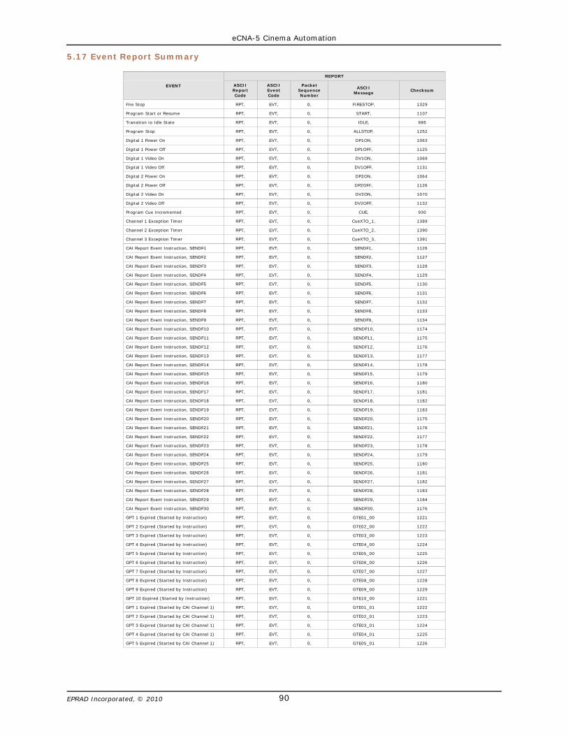
eCNA-5 Cinema Automation
90EPRAD Incorporated, © 2010
5.17 Event Report Summary
EVENT
REPORT
ASCIIReportCode
ASCIIEventCode
PacketSequenceNumber
ASCIIMessage Checksum
Fire Stop RPT, EVT, 0, FIRESTOP, 1329
Program Start or Resume RPT, EVT, 0, START, 1107
Transition to Idle State RPT, EVT, 0, IDLE, 995
Program Stop RPT, EVT, 0, ALLSTOP, 1252
Digital 1 Power On RPT, EVT, 0, DP1ON, 1063
Digital 1 Power Off RPT, EVT, 0, DP1OFF, 1125
Digital 1 Video On RPT, EVT, 0, DV1ON, 1069
Digital 1 Video Off RPT, EVT, 0, DV1OFF, 1131
Digital 2 Power On RPT, EVT, 0, DP2ON, 1064
Digital 2 Power Off RPT, EVT, 0, DP2OFF, 1126
Digital 2 Video On RPT, EVT, 0, DV2ON, 1070
Digital 2 Video Off RPT, EVT, 0, DV2OFF, 1132
Program Cue Incremented RPT, EVT, 0, CUE, 930
Channel 1 Exception Timer RPT, EVT, 0, CueXTO_1, 1389
Channel 2 Exception Timer RPT, EVT, 0, CueXTO_2, 1390
Channel 3 Exception Timer RPT, EVT, 0, CueXTO_3, 1391
CAI Report Event Instruction, SENDF1 RPT, EVT, 0, SENDF1, 1126
CAI Report Event Instruction, SENDF2 RPT, EVT, 0, SENDF2, 1127
CAI Report Event Instruction, SENDF3 RPT, EVT, 0, SENDF3, 1128
CAI Report Event Instruction, SENDF4 RPT, EVT, 0, SENDF4, 1129
CAI Report Event Instruction, SENDF5 RPT, EVT, 0, SENDF5, 1130
CAI Report Event Instruction, SENDF6 RPT, EVT, 0, SENDF6, 1131
CAI Report Event Instruction, SENDF7 RPT, EVT, 0, SENDF7, 1132
CAI Report Event Instruction, SENDF8 RPT, EVT, 0, SENDF8, 1133
CAI Report Event Instruction, SENDF9 RPT, EVT, 0, SENDF9, 1134
CAI Report Event Instruction, SENDF10 RPT, EVT, 0, SENDF10, 1174
CAI Report Event Instruction, SENDF11 RPT, EVT, 0, SENDF11, 1175
CAI Report Event Instruction, SENDF12 RPT, EVT, 0, SENDF12, 1176
CAI Report Event Instruction, SENDF13 RPT, EVT, 0, SENDF13, 1177
CAI Report Event Instruction, SENDF14 RPT, EVT, 0, SENDF14, 1178
CAI Report Event Instruction, SENDF15 RPT, EVT, 0, SENDF15, 1179
CAI Report Event Instruction, SENDF16 RPT, EVT, 0, SENDF16, 1180
CAI Report Event Instruction, SENDF17 RPT, EVT, 0, SENDF17, 1181
CAI Report Event Instruction, SENDF18 RPT, EVT, 0, SENDF18, 1182
CAI Report Event Instruction, SENDF19 RPT, EVT, 0, SENDF19, 1183
CAI Report Event Instruction, SENDF20 RPT, EVT, 0, SENDF20, 1175
CAI Report Event Instruction, SENDF21 RPT, EVT, 0, SENDF21, 1176
CAI Report Event Instruction, SENDF22 RPT, EVT, 0, SENDF22, 1177
CAI Report Event Instruction, SENDF23 RPT, EVT, 0, SENDF23, 1178
CAI Report Event Instruction, SENDF24 RPT, EVT, 0, SENDF24, 1179
CAI Report Event Instruction, SENDF25 RPT, EVT, 0, SENDF25, 1180
CAI Report Event Instruction, SENDF26 RPT, EVT, 0, SENDF26, 1181
CAI Report Event Instruction, SENDF27 RPT, EVT, 0, SENDF27, 1182
CAI Report Event Instruction, SENDF28 RPT, EVT, 0, SENDF28, 1183
CAI Report Event Instruction, SENDF29 RPT, EVT, 0, SENDF29, 1184
CAI Report Event Instruction, SENDF30 RPT, EVT, 0, SENDF30, 1176
GPT 1 Expired (Started by Instruction) RPT, EVT, 0, GTE01_00 1221
GPT 2 Expired (Started by Instruction) RPT, EVT, 0, GTE02_00 1222
GPT 3 Expired (Started by Instruction) RPT, EVT, 0, GTE03_00 1223
GPT 4 Expired (Started by Instruction) RPT, EVT, 0, GTE04_00 1224
GPT 5 Expired (Started by Instruction) RPT, EVT, 0, GTE05_00 1225
GPT 6 Expired (Started by Instruction) RPT, EVT, 0, GTE06_00 1226
GPT 7 Expired (Started by Instruction) RPT, EVT, 0, GTE07_00 1227
GPT 8 Expired (Started by Instruction) RPT, EVT, 0, GTE08_00 1228
GPT 9 Expired (Started by Instruction) RPT, EVT, 0, GTE09_00 1229
GPT 10 Expired (Started by Instruction) RPT, EVT, 0, GTE10_00 1221
GPT 1 Expired (Started by CAI Channel 1) RPT, EVT, 0, GTE01_01 1222
GPT 2 Expired (Started by CAI Channel 1) RPT, EVT, 0, GTE02_01 1223
GPT 3 Expired (Started by CAI Channel 1) RPT, EVT, 0, GTE03_01 1224
GPT 4 Expired (Started by CAI Channel 1) RPT, EVT, 0, GTE04_01 1225
GPT 5 Expired (Started by CAI Channel 1) RPT, EVT, 0, GTE05_01 1226

eCNA-5 Cinema Automation
91EPRAD Incorporated, © 2010
Event Report Summary (continued)
EVENT
REPORT
ASCIIReportCode
ASCIIEventCode
PacketSequenceNumber
ASCIIMessage Checksum
GPT 6 Expired (Started by CAI Channel 1) RPT, EVT, 0, GTE06_01 1227
GPT 7 Expired (Started by CAI Channel 1) RPT, EVT, 0, GTE07_01 1228
GPT 8 Expired (Started by CAI Channel 1) RPT, EVT, 0, GTE08_01 1229
GPT 9 Expired (Started by CAI Channel 1) RPT, EVT, 0, GTE09_01 1230
GPT 10 Expired (Started by CAI Channel 1) RPT, EVT, 0, GTE10_01 1222
GPT 1 Expired (Started by CAI Channel 2) RPT, EVT, 0, GTE01_02 1223
GPT 2 Expired (Started by CAI Channel 2) RPT, EVT, 0, GTE02_02 1224
GPT 3 Expired (Started by CAI Channel 2) RPT, EVT, 0, GTE03_02 1225
GPT 4 Expired (Started by CAI Channel 2) RPT, EVT, 0, GTE04_02 1226
GPT 5 Expired (Started by CAI Channel 2) RPT, EVT, 0, GTE05_02 1227
GPT 6 Expired (Started by CAI Channel 2) RPT, EVT, 0, GTE06_02 1228
GPT 7 Expired (Started by CAI Channel 2) RPT, EVT, 0, GTE07_02 1229
GPT 8 Expired (Started by CAI Channel 2) RPT, EVT, 0, GTE08_02 1230
GPT 9 Expired (Started by CAI Channel 2) RPT, EVT, 0, GTE09_02 1231
GPT 10 Expired (Started by CAI Channel 2) RPT, EVT, 0, GTE10_02 1223
GPT 1 Expired (Started by CAI Channel 3) RPT, EVT, 0, GTE01_03 1224
GPT 2 Expired (Started by CAI Channel 3) RPT, EVT, 0, GTE02_03 1225
GPT 3 Expired (Started by CAI Channel 3) RPT, EVT, 0, GTE03_03 1226
GPT 4 Expired (Started by CAI Channel 3) RPT, EVT, 0, GTE04_03 1227
GPT 5 Expired (Started by CAI Channel 3) RPT, EVT, 0, GTE05_03 1228
GPT 6 Expired (Started by CAI Channel 3) RPT, EVT, 0, GTE06_03 1229
GPT 7 Expired (Started by CAI Channel 3) RPT, EVT, 0, GTE07_03 1230
GPT 8 Expired (Started by CAI Channel 3) RPT, EVT, 0, GTE08_03 1231
GPT 9 Expired (Started by CAI Channel 3) RPT, EVT, 0, GTE09_03 1232
GPT 10 Expired (Started by CAI Channel 3) RPT, EVT, 0, GTE10_03 1224
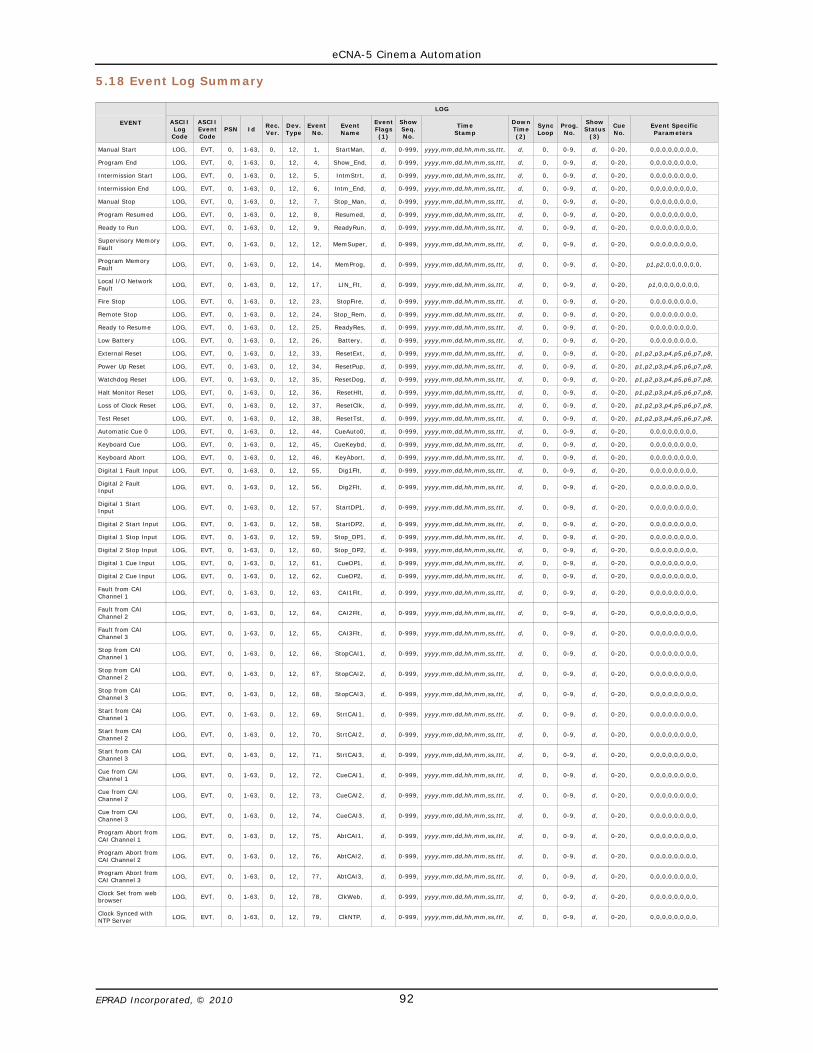
eCNA-5 Cinema Automation
92EPRAD Incorporated, © 2010
5.18 Event Log Summary
EVENT
LOG
ASCIILog
Code
ASCIIEventCode
PSN IdRec.Ver.
Dev.Type
Event No.
EventName
EventFlags(1)
ShowSeq.No.
TimeStamp
DownTime(2)
SyncLoop
Prog.No.
ShowStatus
(3)
CueNo.
Event SpecificParameters
Manual Start LOG, EVT, 0, 1-63, 0, 12, 1, StartMan, d, 0-999, yyyy,mm,dd,hh,mm,ss,ttt, d, 0, 0-9, d, 0-20, 0,0,0,0,0,0,0,0,
Program End LOG, EVT, 0, 1-63, 0, 12, 4, Show_End, d, 0-999, yyyy,mm,dd,hh,mm,ss,ttt, d, 0, 0-9, d, 0-20, 0,0,0,0,0,0,0,0,
Intermission Start LOG, EVT, 0, 1-63, 0, 12, 5, IntmStrt, d, 0-999, yyyy,mm,dd,hh,mm,ss,ttt, d, 0, 0-9, d, 0-20, 0,0,0,0,0,0,0,0,
Intermission End LOG, EVT, 0, 1-63, 0, 12, 6, Intm_End, d, 0-999, yyyy,mm,dd,hh,mm,ss,ttt, d, 0, 0-9, d, 0-20, 0,0,0,0,0,0,0,0,
Manual Stop LOG, EVT, 0, 1-63, 0, 12, 7, Stop_Man, d, 0-999, yyyy,mm,dd,hh,mm,ss,ttt, d, 0, 0-9, d, 0-20, 0,0,0,0,0,0,0,0,
Program Resumed LOG, EVT, 0, 1-63, 0, 12, 8, Resumed, d, 0-999, yyyy,mm,dd,hh,mm,ss,ttt, d, 0, 0-9, d, 0-20, 0,0,0,0,0,0,0,0,
Ready to Run LOG, EVT, 0, 1-63, 0, 12, 9, ReadyRun, d, 0-999, yyyy,mm,dd,hh,mm,ss,ttt, d, 0, 0-9, d, 0-20, 0,0,0,0,0,0,0,0,
Supervisory MemoryFault
LOG, EVT, 0, 1-63, 0, 12, 12, MemSuper, d, 0-999, yyyy,mm,dd,hh,mm,ss,ttt, d, 0, 0-9, d, 0-20, 0,0,0,0,0,0,0,0,
Program MemoryFault
LOG, EVT, 0, 1-63, 0, 12, 14, MemProg, d, 0-999, yyyy,mm,dd,hh,mm,ss,ttt, d, 0, 0-9, d, 0-20, p1,p2,0,0,0,0,0,0,
Local I/O NetworkFault
LOG, EVT, 0, 1-63, 0, 12, 17, LIN_Flt, d, 0-999, yyyy,mm,dd,hh,mm,ss,ttt, d, 0, 0-9, d, 0-20, p1,0,0,0,0,0,0,0,
Fire Stop LOG, EVT, 0, 1-63, 0, 12, 23, StopFire, d, 0-999, yyyy,mm,dd,hh,mm,ss,ttt, d, 0, 0-9, d, 0-20, 0,0,0,0,0,0,0,0,
Remote Stop LOG, EVT, 0, 1-63, 0, 12, 24, Stop_Rem, d, 0-999, yyyy,mm,dd,hh,mm,ss,ttt, d, 0, 0-9, d, 0-20, 0,0,0,0,0,0,0,0,
Ready to Resume LOG, EVT, 0, 1-63, 0, 12, 25, ReadyRes, d, 0-999, yyyy,mm,dd,hh,mm,ss,ttt, d, 0, 0-9, d, 0-20, 0,0,0,0,0,0,0,0,
Low Battery LOG, EVT, 0, 1-63, 0, 12, 26, Battery, d, 0-999, yyyy,mm,dd,hh,mm,ss,ttt, d, 0, 0-9, d, 0-20, 0,0,0,0,0,0,0,0,
External Reset LOG, EVT, 0, 1-63, 0, 12, 33, ResetExt, d, 0-999, yyyy,mm,dd,hh,mm,ss,ttt, d, 0, 0-9, d, 0-20, p1,p2,p3,p4,p5,p6,p7,p8,
Power Up Reset LOG, EVT, 0, 1-63, 0, 12, 34, ResetPup, d, 0-999, yyyy,mm,dd,hh,mm,ss,ttt, d, 0, 0-9, d, 0-20, p1,p2,p3,p4,p5,p6,p7,p8,
Watchdog Reset LOG, EVT, 0, 1-63, 0, 12, 35, ResetDog, d, 0-999, yyyy,mm,dd,hh,mm,ss,ttt, d, 0, 0-9, d, 0-20, p1,p2,p3,p4,p5,p6,p7,p8,
Halt Monitor Reset LOG, EVT, 0, 1-63, 0, 12, 36, ResetHlt, d, 0-999, yyyy,mm,dd,hh,mm,ss,ttt, d, 0, 0-9, d, 0-20, p1,p2,p3,p4,p5,p6,p7,p8,
Loss of Clock Reset LOG, EVT, 0, 1-63, 0, 12, 37, ResetClk, d, 0-999, yyyy,mm,dd,hh,mm,ss,ttt, d, 0, 0-9, d, 0-20, p1,p2,p3,p4,p5,p6,p7,p8,
Test Reset LOG, EVT, 0, 1-63, 0, 12, 38, ResetTst, d, 0-999, yyyy,mm,dd,hh,mm,ss,ttt, d, 0, 0-9, d, 0-20, p1,p2,p3,p4,p5,p6,p7,p8,
Automatic Cue 0 LOG, EVT, 0, 1-63, 0, 12, 44, CueAuto0, d, 0-999, yyyy,mm,dd,hh,mm,ss,ttt, d, 0, 0-9, d, 0-20, 0,0,0,0,0,0,0,0,
Keyboard Cue LOG, EVT, 0, 1-63, 0, 12, 45, CueKeybd, d, 0-999, yyyy,mm,dd,hh,mm,ss,ttt, d, 0, 0-9, d, 0-20, 0,0,0,0,0,0,0,0,
Keyboard Abort LOG, EVT, 0, 1-63, 0, 12, 46, KeyAbort, d, 0-999, yyyy,mm,dd,hh,mm,ss,ttt, d, 0, 0-9, d, 0-20, 0,0,0,0,0,0,0,0,
Digital 1 Fault Input LOG, EVT, 0, 1-63, 0, 12, 55, Dig1Flt, d, 0-999, yyyy,mm,dd,hh,mm,ss,ttt, d, 0, 0-9, d, 0-20, 0,0,0,0,0,0,0,0,
Digital 2 FaultInput
LOG, EVT, 0, 1-63, 0, 12, 56, Dig2Flt, d, 0-999, yyyy,mm,dd,hh,mm,ss,ttt, d, 0, 0-9, d, 0-20, 0,0,0,0,0,0,0,0,
Digital 1 StartInput
LOG, EVT, 0, 1-63, 0, 12, 57, StartDP1, d, 0-999, yyyy,mm,dd,hh,mm,ss,ttt, d, 0, 0-9, d, 0-20, 0,0,0,0,0,0,0,0,
Digital 2 Start Input LOG, EVT, 0, 1-63, 0, 12, 58, StartDP2, d, 0-999, yyyy,mm,dd,hh,mm,ss,ttt, d, 0, 0-9, d, 0-20, 0,0,0,0,0,0,0,0,
Digital 1 Stop Input LOG, EVT, 0, 1-63, 0, 12, 59, Stop_DP1, d, 0-999, yyyy,mm,dd,hh,mm,ss,ttt, d, 0, 0-9, d, 0-20, 0,0,0,0,0,0,0,0,
Digital 2 Stop Input LOG, EVT, 0, 1-63, 0, 12, 60, Stop_DP2, d, 0-999, yyyy,mm,dd,hh,mm,ss,ttt, d, 0, 0-9, d, 0-20, 0,0,0,0,0,0,0,0,
Digital 1 Cue Input LOG, EVT, 0, 1-63, 0, 12, 61, CueDP1, d, 0-999, yyyy,mm,dd,hh,mm,ss,ttt, d, 0, 0-9, d, 0-20, 0,0,0,0,0,0,0,0,
Digital 2 Cue Input LOG, EVT, 0, 1-63, 0, 12, 62, CueDP2, d, 0-999, yyyy,mm,dd,hh,mm,ss,ttt, d, 0, 0-9, d, 0-20, 0,0,0,0,0,0,0,0,
Fault from CAIChannel 1
LOG, EVT, 0, 1-63, 0, 12, 63, CAI1Flt, d, 0-999, yyyy,mm,dd,hh,mm,ss,ttt, d, 0, 0-9, d, 0-20, 0,0,0,0,0,0,0,0,
Fault from CAIChannel 2
LOG, EVT, 0, 1-63, 0, 12, 64, CAI2Flt, d, 0-999, yyyy,mm,dd,hh,mm,ss,ttt, d, 0, 0-9, d, 0-20, 0,0,0,0,0,0,0,0,
Fault from CAIChannel 3
LOG, EVT, 0, 1-63, 0, 12, 65, CAI3Flt, d, 0-999, yyyy,mm,dd,hh,mm,ss,ttt, d, 0, 0-9, d, 0-20, 0,0,0,0,0,0,0,0,
Stop from CAIChannel 1
LOG, EVT, 0, 1-63, 0, 12, 66, StopCAI1, d, 0-999, yyyy,mm,dd,hh,mm,ss,ttt, d, 0, 0-9, d, 0-20, 0,0,0,0,0,0,0,0,
Stop from CAIChannel 2
LOG, EVT, 0, 1-63, 0, 12, 67, StopCAI2, d, 0-999, yyyy,mm,dd,hh,mm,ss,ttt, d, 0, 0-9, d, 0-20, 0,0,0,0,0,0,0,0,
Stop from CAIChannel 3
LOG, EVT, 0, 1-63, 0, 12, 68, StopCAI3, d, 0-999, yyyy,mm,dd,hh,mm,ss,ttt, d, 0, 0-9, d, 0-20, 0,0,0,0,0,0,0,0,
Start from CAIChannel 1
LOG, EVT, 0, 1-63, 0, 12, 69, StrtCAI1, d, 0-999, yyyy,mm,dd,hh,mm,ss,ttt, d, 0, 0-9, d, 0-20, 0,0,0,0,0,0,0,0,
Start from CAIChannel 2
LOG, EVT, 0, 1-63, 0, 12, 70, StrtCAI2, d, 0-999, yyyy,mm,dd,hh,mm,ss,ttt, d, 0, 0-9, d, 0-20, 0,0,0,0,0,0,0,0,
Start from CAIChannel 3
LOG, EVT, 0, 1-63, 0, 12, 71, StrtCAI3, d, 0-999, yyyy,mm,dd,hh,mm,ss,ttt, d, 0, 0-9, d, 0-20, 0,0,0,0,0,0,0,0,
Cue from CAIChannel 1
LOG, EVT, 0, 1-63, 0, 12, 72, CueCAI1, d, 0-999, yyyy,mm,dd,hh,mm,ss,ttt, d, 0, 0-9, d, 0-20, 0,0,0,0,0,0,0,0,
Cue from CAIChannel 2
LOG, EVT, 0, 1-63, 0, 12, 73, CueCAI2, d, 0-999, yyyy,mm,dd,hh,mm,ss,ttt, d, 0, 0-9, d, 0-20, 0,0,0,0,0,0,0,0,
Cue from CAIChannel 3
LOG, EVT, 0, 1-63, 0, 12, 74, CueCAI3, d, 0-999, yyyy,mm,dd,hh,mm,ss,ttt, d, 0, 0-9, d, 0-20, 0,0,0,0,0,0,0,0,
Program Abort fromCAI Channel 1
LOG, EVT, 0, 1-63, 0, 12, 75, AbtCAI1, d, 0-999, yyyy,mm,dd,hh,mm,ss,ttt, d, 0, 0-9, d, 0-20, 0,0,0,0,0,0,0,0,
Program Abort fromCAI Channel 2
LOG, EVT, 0, 1-63, 0, 12, 76, AbtCAI2, d, 0-999, yyyy,mm,dd,hh,mm,ss,ttt, d, 0, 0-9, d, 0-20, 0,0,0,0,0,0,0,0,
Program Abort fromCAI Channel 3
LOG, EVT, 0, 1-63, 0, 12, 77, AbtCAI3, d, 0-999, yyyy,mm,dd,hh,mm,ss,ttt, d, 0, 0-9, d, 0-20, 0,0,0,0,0,0,0,0,
Clock Set from webbrowser
LOG, EVT, 0, 1-63, 0, 12, 78, ClkWeb, d, 0-999, yyyy,mm,dd,hh,mm,ss,ttt, d, 0, 0-9, d, 0-20, 0,0,0,0,0,0,0,0,
Clock Synced withNTP Server
LOG, EVT, 0, 1-63, 0, 12, 79, ClkNTP, d, 0-999, yyyy,mm,dd,hh,mm,ss,ttt, d, 0, 0-9, d, 0-20, 0,0,0,0,0,0,0,0,
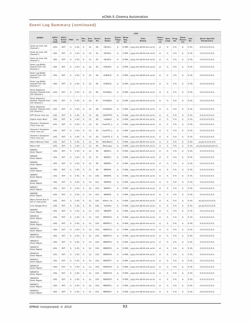
eCNA-5 Cinema Automation
93EPRAD Incorporated, © 2010
Event Log Summary (continued)
EVENT
LOG
ASCIILog
Code
ASCIIEventCode
PSN IdRec.Ver.
Dev.Type
Event No.
EventName
EventFlags(1)
ShowSeq.No.
TimeStamp
DownTime(2)
SyncLoop
Prog.No.
ShowStatus
(3)
CueNo.
Event SpecificParameters
Clock set from CAIChannel 1
LOG, EVT, 0, 1-63, 0, 12, 80, ClkCAI1, d, 0-999, yyyy,mm,dd,hh,mm,ss,ttt, d, 0, 0-9, d, 0-20, 0,0,0,0,0,0,0,0,
Clock set from CAIChannel 2
LOG, EVT, 0, 1-63, 0, 12, 81, ClkCAI2, d, 0-999, yyyy,mm,dd,hh,mm,ss,ttt, d, 0, 0-9, d, 0-20, 0,0,0,0,0,0,0,0,
Clock set from CAIChannel 3
LOG, EVT, 0, 1-63, 0, 12, 82, ClkCAI3, d, 0-999, yyyy,mm,dd,hh,mm,ss,ttt, d, 0, 0-9, d, 0-20, 0,0,0,0,0,0,0,0,
Event Log Buffercleared from CAIChannel 1
LOG, EVT, 0, 1-63, 0, 12, 83, ClrBufC1, d, 0-999, yyyy,mm,dd,hh,mm,ss,ttt, d, 0, 0-9, d, 0-20, 0,0,0,0,0,0,0,0,
Event Log Buffercleared from CAIChannel 2
LOG, EVT, 0, 1-63, 0, 12, 84, ClrBufC2, d, 0-999, yyyy,mm,dd,hh,mm,ss,ttt, d, 0, 0-9, d, 0-20, 0,0,0,0,0,0,0,0,
Event Log Buffercleared from CAIChannel 3
LOG, EVT, 0, 1-63, 0, 12, 85, ClrBufC3, d, 0-999, yyyy,mm,dd,hh,mm,ss,ttt, d, 0, 0-9, d, 0-20, 0,0,0,0,0,0,0,0,
Show SequenceNumber Cleared fromCAI Channel 1
LOG, EVT, 0, 1-63, 0, 12, 86, ClrSSQC1, d, 0-999, yyyy,mm,dd,hh,mm,ss,ttt, d, 0, 0-9, d, 0-20, 0,0,0,0,0,0,0,0,
Show SequenceNumber Cleared fromCAI Channel 1
LOG, EVT, 0, 1-63, 0, 12, 87, ClrSSQC2, d, 0-999, yyyy,mm,dd,hh,mm,ss,ttt, d, 0, 0-9, d, 0-20, 0,0,0,0,0,0,0,0,
Show SequenceNumber Cleared fromCAI Channel 1
LOG, EVT, 0, 1-63, 0, 12, 88, ClrSSQC3, d, 0-999, yyyy,mm,dd,hh,mm,ss,ttt, d, 0, 0-9, d, 0-20, 0,0,0,0,0,0,0,0,
NTP Server time out LOG, EVT, 0, 1-63, 0, 12, 89, ClkNTPTO, d, 0-999, yyyy,mm,dd,hh,mm,ss,ttt, d, 0, 0-9, d, 0-20, 0,0,0,0,0,0,0,0,
Digital Input Abort LOG, EVT, 0, 1-63, 0, 12, 90, InpAbort d, 0-999, yyyy,mm,dd,hh,mm,ss,ttt, d, 0, 0-9, d, 0-20, 0,0,0,0,0,0,0,0,
Channel 1 ExceptionTimer time out
LOG, EVT, 0, 1-63, 0, 12, 91, CueXTO_1, d, 0-999, yyyy,mm,dd,hh,mm,ss,ttt, d, 0, 0-9, d, 0-20, 0,0,0,0,0,0,0,0,
Channel 2 ExceptionTimer time out
LOG, EVT, 0, 1-63, 0, 12, 92, CueXTO_2, d, 0-999, yyyy,mm,dd,hh,mm,ss,ttt, d, 0, 0-9, d, 0-20, 0,0,0,0,0,0,0,0,
Channel 3 ExceptionTimer time out
LOG, EVT, 0, 1-63, 0, 12, 93, CueXTO_3, d, 0-999, yyyy,mm,dd,hh,mm,ss,ttt, d, 0, 0-9, d, 0-20, 0,0,0,0,0,0,0,0,
Macro Memory Fault LOG, EVT, 0, 1-63, 0, 12, 94, MemMacro, d, 0-999, yyyy,mm,dd,hh,mm,ss,ttt, d, 0, 0-9, d, 0-20, p1,p2,0,0,0,0,0,0,
Macro Call LOG, EVT, 0, 1-63, 0, 12, 95, Macxxayy, d, 0-999, yyyy,mm,dd,hh,mm,ss,ttt, d, 0, 0-9, d, 0-20, p1,p2,p3,p4,p5,p6,0,0,
SENDF1 Event Report
LOG, EVT, 0, 1-63, 0, 12, 96, SENDF1, d, 0-999, yyyy,mm,dd,hh,mm,ss,ttt, d, 0, 0-9, d, 0-20, 0,0,0,0,0,0,0,0,
SENDF2 Event Report
LOG, EVT, 0, 1-63, 0, 12, 97, SENDF2, d, 0-999, yyyy,mm,dd,hh,mm,ss,ttt, d, 0, 0-9, d, 0-20, 0,0,0,0,0,0,0,0,
SENDF3 Event Report
LOG, EVT, 0, 1-63, 0, 12, 98, SENDF3, d, 0-999, yyyy,mm,dd,hh,mm,ss,ttt, d, 0, 0-9, d, 0-20, 0,0,0,0,0,0,0,0,
SENDF4Event Report
LOG, EVT, 0, 1-63, 0, 12, 99, SENDF4, d, 0-999, yyyy,mm,dd,hh,mm,ss,ttt, d, 0, 0-9, d, 0-20, 0,0,0,0,0,0,0,0,
SENDF5 Event Report
LOG, EVT, 0, 1-63, 0, 12, 100, SENDF5, d, 0-999, yyyy,mm,dd,hh,mm,ss,ttt, d, 0, 0-9, d, 0-20, 0,0,0,0,0,0,0,0,
SENDF6 Event Report
LOG, EVT, 0, 1-63, 0, 12, 101, SENDF6, d, 0-999, yyyy,mm,dd,hh,mm,ss,ttt, d, 0, 0-9, d, 0-20, 0,0,0,0,0,0,0,0,
SENDF7 Event Report
LOG, EVT, 0, 1-63, 0, 12, 102, SENDF7, d, 0-999, yyyy,mm,dd,hh,mm,ss,ttt, d, 0, 0-9, d, 0-20, 0,0,0,0,0,0,0,0,
SENDF8Event Report
LOG, EVT, 0, 1-63, 0, 12, 103, SENDF8, d, 0-999, yyyy,mm,dd,hh,mm,ss,ttt, d, 0, 0-9, d, 0-20, 0,0,0,0,0,0,0,0,
Macro Exited due toExit If Instruction
LOG, EVT, 0, 1-63, 0, 12, 104, Xifmm_nn, d, 0-999, yyyy,mm,dd,hh,mm,ss,ttt, d, 0, 0-9, d, 0-20, p1,p2,0,0,0,0,0,0,
Line Voltage Hi/Lo LOG, EVT, 0, 1-63, 0, 12, 105, VoltHiLo d, 0-999, yyyy,mm,dd,hh,mm,ss,ttt, d, 0, 0-9, d, 0-20, p1,p2,0,0,0,0,0,0,
SENDF9Event Report
LOG, EVT, 0, 1-63, 0, 12, 103, SENDF9, d, 0-999, yyyy,mm,dd,hh,mm,ss,ttt, d, 0, 0-9, d, 0-20, 0,0,0,0,0,0,0,0,
SENDF10Event Report
LOG, EVT, 0, 1-63, 0, 12, 103, SENDF10, d, 0-999, yyyy,mm,dd,hh,mm,ss,ttt, d, 0, 0-9, d, 0-20, 0,0,0,0,0,0,0,0,
SENDF11Event Report
LOG, EVT, 0, 1-63, 0, 12, 103, SENDF11, d, 0-999, yyyy,mm,dd,hh,mm,ss,ttt, d, 0, 0-9, d, 0-20, 0,0,0,0,0,0,0,0,
SENDF12Event Report
LOG, EVT, 0, 1-63, 0, 12, 103, SENDF12, d, 0-999, yyyy,mm,dd,hh,mm,ss,ttt, d, 0, 0-9, d, 0-20, 0,0,0,0,0,0,0,0,
SENDF13Event Report
LOG, EVT, 0, 1-63, 0, 12, 103, SENDF13, d, 0-999, yyyy,mm,dd,hh,mm,ss,ttt, d, 0, 0-9, d, 0-20, 0,0,0,0,0,0,0,0,
SENDF14Event Report
LOG, EVT, 0, 1-63, 0, 12, 103, SENDF14, d, 0-999, yyyy,mm,dd,hh,mm,ss,ttt, d, 0, 0-9, d, 0-20, 0,0,0,0,0,0,0,0,
SENDF15Event Report
LOG, EVT, 0, 1-63, 0, 12, 103, SENDF15, d, 0-999, yyyy,mm,dd,hh,mm,ss,ttt, d, 0, 0-9, d, 0-20, 0,0,0,0,0,0,0,0,
SENDF16Event Report
LOG, EVT, 0, 1-63, 0, 12, 103, SENDF16, d, 0-999, yyyy,mm,dd,hh,mm,ss,ttt, d, 0, 0-9, d, 0-20, 0,0,0,0,0,0,0,0,
SENDF17Event Report
LOG, EVT, 0, 1-63, 0, 12, 103, SENDF17, d, 0-999, yyyy,mm,dd,hh,mm,ss,ttt, d, 0, 0-9, d, 0-20, 0,0,0,0,0,0,0,0,
SENDF18Event Report
LOG, EVT, 0, 1-63, 0, 12, 103, SENDF18, d, 0-999, yyyy,mm,dd,hh,mm,ss,ttt, d, 0, 0-9, d, 0-20, 0,0,0,0,0,0,0,0,
SENDF19Event Report
LOG, EVT, 0, 1-63, 0, 12, 103, SENDF19, d, 0-999, yyyy,mm,dd,hh,mm,ss,ttt, d, 0, 0-9, d, 0-20, 0,0,0,0,0,0,0,0,
SENDF20Event Report
LOG, EVT, 0, 1-63, 0, 12, 103, SENDF20, d, 0-999, yyyy,mm,dd,hh,mm,ss,ttt, d, 0, 0-9, d, 0-20, 0,0,0,0,0,0,0,0,
SENDF21Event Report
LOG, EVT, 0, 1-63, 0, 12, 103, SENDF21, d, 0-999, yyyy,mm,dd,hh,mm,ss,ttt, d, 0, 0-9, d, 0-20, 0,0,0,0,0,0,0,0,
SENDF22Event Report
LOG, EVT, 0, 1-63, 0, 12, 103, SENDF22, d, 0-999, yyyy,mm,dd,hh,mm,ss,ttt, d, 0, 0-9, d, 0-20, 0,0,0,0,0,0,0,0,
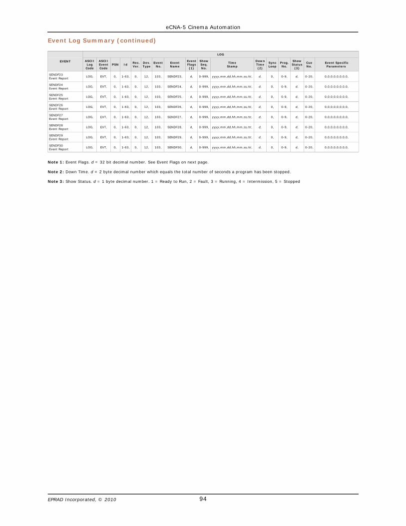
eCNA-5 Cinema Automation
94EPRAD Incorporated, © 2010
Event Log Summary (continued)
EVENT
LOG
ASCIILog
Code
ASCIIEventCode
PSN IdRec.Ver.
Dev.Type
Event No.
EventName
EventFlags(1)
ShowSeq.No.
TimeStamp
DownTime(2)
SyncLoop
Prog.No.
ShowStatus
(3)
CueNo.
Event SpecificParameters
SENDF23Event Report
LOG, EVT, 0, 1-63, 0, 12, 103, SENDF23, d, 0-999, yyyy,mm,dd,hh,mm,ss,ttt, d, 0, 0-9, d, 0-20, 0,0,0,0,0,0,0,0,
SENDF24Event Report
LOG, EVT, 0, 1-63, 0, 12, 103, SENDF24, d, 0-999, yyyy,mm,dd,hh,mm,ss,ttt, d, 0, 0-9, d, 0-20, 0,0,0,0,0,0,0,0,
SENDF25Event Report
LOG, EVT, 0, 1-63, 0, 12, 103, SENDF25, d, 0-999, yyyy,mm,dd,hh,mm,ss,ttt, d, 0, 0-9, d, 0-20, 0,0,0,0,0,0,0,0,
SENDF26Event Report
LOG, EVT, 0, 1-63, 0, 12, 103, SENDF26, d, 0-999, yyyy,mm,dd,hh,mm,ss,ttt, d, 0, 0-9, d, 0-20, 0,0,0,0,0,0,0,0,
SENDF27Event Report
LOG, EVT, 0, 1-63, 0, 12, 103, SENDF27, d, 0-999, yyyy,mm,dd,hh,mm,ss,ttt, d, 0, 0-9, d, 0-20, 0,0,0,0,0,0,0,0,
SENDF28Event Report
LOG, EVT, 0, 1-63, 0, 12, 103, SENDF28, d, 0-999, yyyy,mm,dd,hh,mm,ss,ttt, d, 0, 0-9, d, 0-20, 0,0,0,0,0,0,0,0,
SENDF29Event Report
LOG, EVT, 0, 1-63, 0, 12, 103, SENDF29, d, 0-999, yyyy,mm,dd,hh,mm,ss,ttt, d, 0, 0-9, d, 0-20, 0,0,0,0,0,0,0,0,
SENDF30Event Report
LOG, EVT, 0, 1-63, 0, 12, 103, SENDF30, d, 0-999, yyyy,mm,dd,hh,mm,ss,ttt, d, 0, 0-9, d, 0-20, 0,0,0,0,0,0,0,0,
Note 1: Event Flags. d = 32 bit decimal number. See Event Flags on next page.
Note 2: Down Time. d = 2 byte decimal number which equals the total number of seconds a program has been stopped.
Note 3: Show Status. d = 1 byte decimal number. 1 = Ready to Run, 2 = Fault, 3 = Running, 4 = Intermission, 5 = Stopped

eCNA-5 Cinema Automation
95EPRAD Incorporated, © 2010
Event Log Summary (continued)
Event Flags
32 bit event flag. Bit 0 is the LSB. This is a decimal number in the range 0 to 232 - 1
Bit 0Bit 1Bit 2Bit 3Bit 4Bit 5Bit 6Bit 7
------------In Progress *------------Running *------------------------------------------------
Bit 8Bit 9Bit 10Bit 11Bit 12Bit 13Bit 14Bit 15
------------------------------------------------------------------------------------------------
Bit 16Bit 17Bit 18Bit 19Bit 20Bit 21Bit 22Bit 23
Any Event **------------Ready to Resume **Ready to Run **User Code **Resume **Cue **Show End **
Bit 24Bit 25Bit 26Bit 27Bit 28Bit 29Bit 30Bit 31
Show Start **Minor Fault **------------Major Fault **Computer **Unscheduled Shutdown **Scheduled Events **Buffer Overflow - Lost Data *
The flag bits can be used to organize events for reporting purposes. These bits represent either run time ‘status’ or event ‘type’ flags.* = Status Flags. These flags are set depending on the status of the eCNA at the time of the event.** = Type Flags. These flags are fixed depending on the type of event.
No. EventBits 0 - 31
31 30 29 28 27 26 25 24 23 22 21 20 19 18 17 16 15 14 13 12 11 10 9 8 7 6 5 4 3 2 1 0
1 StartMan 0 1 0 0 0 0 0 1 0 0 0 0 0 0 0 1 0 0 0 0 0 0 0 0 0 0 0 0 0 0 0 04 Show_End 0 1 0 0 0 0 0 0 1 0 0 0 0 0 0 1 0 0 0 0 0 0 0 0 0 0 0 0 0 0 0 05 IntmStrt 0 1 0 0 0 0 0 0 0 0 0 0 0 0 0 1 0 0 0 0 0 0 0 0 0 0 0 0 0 0 0 06 Intm_End 0 1 0 0 0 0 0 0 0 0 0 0 0 0 0 1 0 0 0 0 0 0 0 0 0 0 0 0 0 0 0 07 Stop_Man 0 0 1 0 0 0 0 0 0 0 0 0 0 0 0 1 0 0 0 0 0 0 0 0 0 0 0 0 0 0 0 08 Resumed 0 0 0 0 0 0 0 0 0 0 1 0 0 0 0 1 0 0 0 0 0 0 0 0 0 0 0 0 0 0 0 09 ReadyRun 0 0 0 0 0 0 0 0 0 0 0 0 1 0 0 1 0 0 0 0 0 0 0 0 0 0 0 0 0 0 0 012 MemSuper 0 0 1 1 1 0 0 0 0 0 0 0 0 0 0 1 0 0 0 0 0 0 0 0 0 0 0 0 0 0 0 014 MemProg 0 0 1 1 1 0 0 0 0 0 0 0 0 0 0 1 0 0 0 0 0 0 0 0 0 0 0 0 0 0 0 017 LIN_Flt 0 0 1 0 1 0 0 0 0 0 0 0 0 0 0 1 0 0 0 0 0 0 0 0 0 0 0 0 0 0 0 023 StopFire 0 0 1 0 1 0 0 0 0 0 0 0 0 0 0 1 0 0 0 0 0 0 0 0 0 0 0 0 0 0 0 024 Stop_Rem 0 0 1 0 1 0 0 0 0 0 0 0 0 0 0 1 0 0 0 0 0 0 0 0 0 0 0 0 0 0 0 025 ReadyRes 0 0 0 0 0 0 0 0 0 0 0 0 0 1 0 1 0 0 0 0 0 0 0 0 0 0 0 0 0 0 0 026 Battery 0 0 0 1 0 0 1 0 0 0 0 0 0 0 0 1 0 0 0 0 0 0 0 0 0 0 0 0 0 0 0 033 ResetExt 0 0 1 1 0 0 0 0 0 0 0 0 0 0 0 1 0 0 0 0 0 0 0 0 0 0 0 0 0 0 0 034 ResetPup 0 0 1 1 0 0 0 0 0 0 0 0 0 0 0 1 0 0 0 0 0 0 0 0 0 0 0 0 0 0 0 035 ResetDog 0 0 1 1 0 0 0 0 0 0 0 0 0 0 0 1 0 0 0 0 0 0 0 0 0 0 0 0 0 0 0 036 ResetHlt 0 0 1 1 0 0 0 0 0 0 0 0 0 0 0 1 0 0 0 0 0 0 0 0 0 0 0 0 0 0 0 037 ResetClk 0 0 1 1 0 0 0 0 0 0 0 0 0 0 0 1 0 0 0 0 0 0 0 0 0 0 0 0 0 0 0 038 ResetTst 0 0 1 1 0 0 0 0 0 0 0 0 0 0 0 1 0 0 0 0 0 0 0 0 0 0 0 0 0 0 0 044 CueAuto0 0 1 0 0 0 0 0 0 0 1 0 0 0 0 0 1 0 0 0 0 0 0 0 0 0 0 0 0 0 0 0 045 CueKeybd 0 0 0 0 0 0 0 0 0 1 0 0 0 0 0 1 0 0 0 0 0 0 0 0 0 0 0 0 0 0 0 046 KeyAbort 0 0 1 0 0 0 0 0 1 0 0 0 0 0 0 1 0 0 0 0 0 0 0 0 0 0 0 0 0 0 0 055 Dig1Flt 0 0 1 0 1 0 0 0 0 0 0 0 0 0 0 1 0 0 0 0 0 0 0 0 0 0 0 0 0 0 0 056 Dig2Flt 0 0 1 0 1 0 0 0 0 0 0 0 0 0 0 1 0 0 0 0 0 0 0 0 0 0 0 0 0 0 0 057 StartDP1 0 1 0 0 0 0 0 1 0 0 0 0 0 0 0 1 0 0 0 0 0 0 0 0 0 0 0 0 0 0 0 058 StartDP2 0 1 0 0 0 0 0 1 0 0 0 0 0 0 0 1 0 0 0 0 0 0 0 0 0 0 0 0 0 0 0 059 Stop_DP1 0 0 1 0 0 0 0 0 0 0 0 0 0 0 0 1 0 0 0 0 0 0 0 0 0 0 0 0 0 0 0 060 Stop_DP2 0 0 1 0 0 0 0 0 0 0 0 0 0 0 0 1 0 0 0 0 0 0 0 0 0 0 0 0 0 0 0 061 CueDP1 0 1 0 0 0 0 0 0 0 1 0 0 0 0 0 1 0 0 0 0 0 0 0 0 0 0 0 0 0 0 0 062 CueDP2 0 1 0 0 0 0 0 0 0 1 0 0 0 0 0 1 0 0 0 0 0 0 0 0 0 0 0 0 0 0 0 063 CAI1Flt 0 0 1 0 1 0 0 0 0 0 0 0 0 0 0 1 0 0 0 0 0 0 0 0 0 0 0 0 0 0 0 064 CAI2Flt 0 0 1 0 1 0 0 0 0 0 0 0 0 0 0 1 0 0 0 0 0 0 0 0 0 0 0 0 0 0 0 065 CAI3Flt 0 0 1 0 1 0 0 0 0 0 0 0 0 0 0 1 0 0 0 0 0 0 0 0 0 0 0 0 0 0 0 066 StopCAI1 0 0 1 0 0 0 0 0 0 0 0 0 0 0 0 1 0 0 0 0 0 0 0 0 0 0 0 0 0 0 0 067 StopCAI2 0 0 1 0 0 0 0 0 0 0 0 0 0 0 0 1 0 0 0 0 0 0 0 0 0 0 0 0 0 0 0 068 StopCAI3 0 0 1 0 0 0 0 0 0 0 0 0 0 0 0 1 0 0 0 0 0 0 0 0 0 0 0 0 0 0 0 069 StrtCAI1 0 1 0 0 0 0 0 1 0 0 0 0 0 0 0 1 0 0 0 0 0 0 0 0 0 0 0 0 0 0 0 070 StrtCAI2 0 1 0 0 0 0 0 1 0 0 0 0 0 0 0 1 0 0 0 0 0 0 0 0 0 0 0 0 0 0 0 071 StrtCAI3 0 1 0 0 0 0 0 1 0 0 0 0 0 0 0 1 0 0 0 0 0 0 0 0 0 0 0 0 0 0 0 072 CueCAI1 0 1 0 0 0 0 0 0 0 1 0 0 0 0 0 1 0 0 0 0 0 0 0 0 0 0 0 0 0 0 0 073 CueCAI2 0 1 0 0 0 0 0 0 0 1 0 0 0 0 0 1 0 0 0 0 0 0 0 0 0 0 0 0 0 0 0 074 CueCAI3 0 1 0 0 0 0 0 0 0 1 0 0 0 0 0 1 0 0 0 0 0 0 0 0 0 0 0 0 0 0 0 075 AbtCAI1 0 0 1 0 0 0 0 0 1 0 0 0 0 0 0 1 0 0 0 0 0 0 0 0 0 0 0 0 0 0 0 076 AbtCAI2 0 0 1 0 0 0 0 0 1 0 0 0 0 0 0 1 0 0 0 0 0 0 0 0 0 0 0 0 0 0 0 077 AbtCAI3 0 0 1 0 0 0 0 0 1 0 0 0 0 0 0 1 0 0 0 0 0 0 0 0 0 0 0 0 0 0 0 078 ClkWeb 0 0 0 0 0 0 0 0 0 0 0 0 0 0 0 1 0 0 0 0 0 0 0 0 0 0 0 0 0 0 0 079 ClkNTP 0 0 0 0 0 0 0 0 0 0 0 0 0 0 0 1 0 0 0 0 0 0 0 0 0 0 0 0 0 0 0 080 ClkCAI1 0 0 0 0 0 0 0 0 0 0 0 0 0 0 0 1 0 0 0 0 0 0 0 0 0 0 0 0 0 0 0 081 ClkCAI2 0 0 0 0 0 0 0 0 0 0 0 0 0 0 0 1 0 0 0 0 0 0 0 0 0 0 0 0 0 0 0 082 ClkCAI3 0 0 0 0 0 0 0 0 0 0 0 0 0 0 0 1 0 0 0 0 0 0 0 0 0 0 0 0 0 0 0 083 ClrBufC1 0 0 0 0 0 0 0 0 0 0 0 0 0 0 0 1 0 0 0 0 0 0 0 0 0 0 0 0 0 0 0 084 ClrBufC2 0 0 0 0 0 0 0 0 0 0 0 0 0 0 0 1 0 0 0 0 0 0 0 0 0 0 0 0 0 0 0 085 ClrBufC3 0 0 0 0 0 0 0 0 0 0 0 0 0 0 0 1 0 0 0 0 0 0 0 0 0 0 0 0 0 0 0 086 ClrSSNC1 0 0 0 0 0 0 0 0 0 0 0 0 0 0 0 1 0 0 0 0 0 0 0 0 0 0 0 0 0 0 0 087 ClrSSNC2 0 0 0 0 0 0 0 0 0 0 0 0 0 0 0 1 0 0 0 0 0 0 0 0 0 0 0 0 0 0 0 088 ClrSSNC3 0 0 0 0 0 0 0 0 0 0 0 0 0 0 0 1 0 0 0 0 0 0 0 0 0 0 0 0 0 0 0 089 ClkNTPTO 0 0 0 0 0 0 0 0 0 0 0 0 0 0 0 1 0 0 0 0 0 0 0 0 0 0 0 0 0 0 0 090 InpAbort 0 0 1 0 0 0 0 0 1 0 0 0 0 0 0 1 0 0 0 0 0 0 0 0 0 0 0 0 0 0 0 091 CueXTO_1 0 0 0 0 0 0 0 0 0 0 0 0 0 0 0 1 0 0 0 0 0 0 0 0 0 0 0 0 0 0 0 092 CueXTO_2 0 0 0 0 0 0 0 0 0 0 0 0 0 0 0 1 0 0 0 0 0 0 0 0 0 0 0 0 0 0 0 093 CueXTO_3 0 0 0 0 0 0 0 0 0 0 0 0 0 0 0 1 0 0 0 0 0 0 0 0 0 0 0 0 0 0 0 094 MemMacro 0 0 1 1 1 0 0 0 0 0 0 0 0 0 0 1 0 0 0 0 0 0 0 0 0 0 0 0 0 0 0 095 Macxxayy 0 0 0 0 0 0 0 0 0 0 0 0 0 0 0 1 0 0 0 0 0 0 0 0 0 0 0 0 0 0 0 0
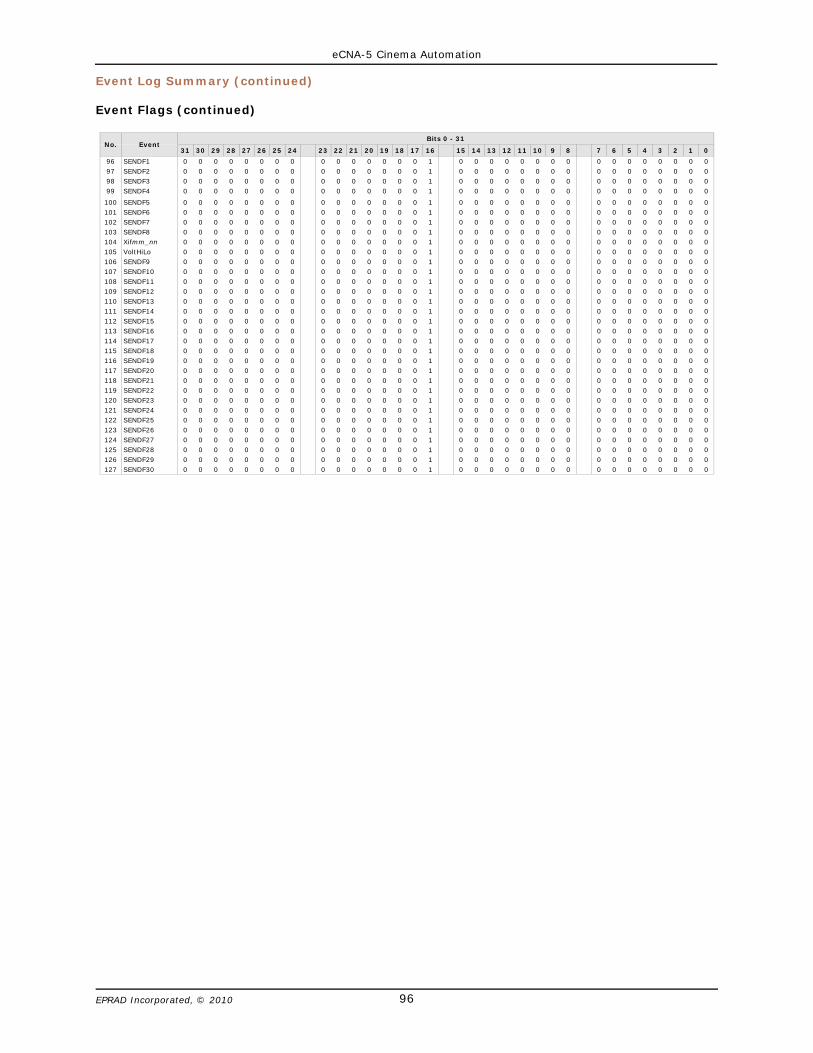
eCNA-5 Cinema Automation
96EPRAD Incorporated, © 2010
Event Log Summary (continued)
Event Flags (continued)
No. EventBits 0 - 31
31 30 29 28 27 26 25 24 23 22 21 20 19 18 17 16 15 14 13 12 11 10 9 8 7 6 5 4 3 2 1 0
96 SENDF1 0 0 0 0 0 0 0 0 0 0 0 0 0 0 0 1 0 0 0 0 0 0 0 0 0 0 0 0 0 0 0 097 SENDF2 0 0 0 0 0 0 0 0 0 0 0 0 0 0 0 1 0 0 0 0 0 0 0 0 0 0 0 0 0 0 0 098 SENDF3 0 0 0 0 0 0 0 0 0 0 0 0 0 0 0 1 0 0 0 0 0 0 0 0 0 0 0 0 0 0 0 099 SENDF4 0 0 0 0 0 0 0 0 0 0 0 0 0 0 0 1 0 0 0 0 0 0 0 0 0 0 0 0 0 0 0 0
100 SENDF5 0 0 0 0 0 0 0 0 0 0 0 0 0 0 0 1 0 0 0 0 0 0 0 0 0 0 0 0 0 0 0 0101 SENDF6 0 0 0 0 0 0 0 0 0 0 0 0 0 0 0 1 0 0 0 0 0 0 0 0 0 0 0 0 0 0 0 0102 SENDF7 0 0 0 0 0 0 0 0 0 0 0 0 0 0 0 1 0 0 0 0 0 0 0 0 0 0 0 0 0 0 0 0103 SENDF8 0 0 0 0 0 0 0 0 0 0 0 0 0 0 0 1 0 0 0 0 0 0 0 0 0 0 0 0 0 0 0 0104 Xifmm_nn 0 0 0 0 0 0 0 0 0 0 0 0 0 0 0 1 0 0 0 0 0 0 0 0 0 0 0 0 0 0 0 0105 VoltHiLo 0 0 0 0 0 0 0 0 0 0 0 0 0 0 0 1 0 0 0 0 0 0 0 0 0 0 0 0 0 0 0 0106 SENDF9 0 0 0 0 0 0 0 0 0 0 0 0 0 0 0 1 0 0 0 0 0 0 0 0 0 0 0 0 0 0 0 0107 SENDF10 0 0 0 0 0 0 0 0 0 0 0 0 0 0 0 1 0 0 0 0 0 0 0 0 0 0 0 0 0 0 0 0108 SENDF11 0 0 0 0 0 0 0 0 0 0 0 0 0 0 0 1 0 0 0 0 0 0 0 0 0 0 0 0 0 0 0 0109 SENDF12 0 0 0 0 0 0 0 0 0 0 0 0 0 0 0 1 0 0 0 0 0 0 0 0 0 0 0 0 0 0 0 0110 SENDF13 0 0 0 0 0 0 0 0 0 0 0 0 0 0 0 1 0 0 0 0 0 0 0 0 0 0 0 0 0 0 0 0111 SENDF14 0 0 0 0 0 0 0 0 0 0 0 0 0 0 0 1 0 0 0 0 0 0 0 0 0 0 0 0 0 0 0 0112 SENDF15 0 0 0 0 0 0 0 0 0 0 0 0 0 0 0 1 0 0 0 0 0 0 0 0 0 0 0 0 0 0 0 0113 SENDF16 0 0 0 0 0 0 0 0 0 0 0 0 0 0 0 1 0 0 0 0 0 0 0 0 0 0 0 0 0 0 0 0114 SENDF17 0 0 0 0 0 0 0 0 0 0 0 0 0 0 0 1 0 0 0 0 0 0 0 0 0 0 0 0 0 0 0 0115 SENDF18 0 0 0 0 0 0 0 0 0 0 0 0 0 0 0 1 0 0 0 0 0 0 0 0 0 0 0 0 0 0 0 0116 SENDF19 0 0 0 0 0 0 0 0 0 0 0 0 0 0 0 1 0 0 0 0 0 0 0 0 0 0 0 0 0 0 0 0117 SENDF20 0 0 0 0 0 0 0 0 0 0 0 0 0 0 0 1 0 0 0 0 0 0 0 0 0 0 0 0 0 0 0 0118 SENDF21 0 0 0 0 0 0 0 0 0 0 0 0 0 0 0 1 0 0 0 0 0 0 0 0 0 0 0 0 0 0 0 0119 SENDF22 0 0 0 0 0 0 0 0 0 0 0 0 0 0 0 1 0 0 0 0 0 0 0 0 0 0 0 0 0 0 0 0120 SENDF23 0 0 0 0 0 0 0 0 0 0 0 0 0 0 0 1 0 0 0 0 0 0 0 0 0 0 0 0 0 0 0 0121 SENDF24 0 0 0 0 0 0 0 0 0 0 0 0 0 0 0 1 0 0 0 0 0 0 0 0 0 0 0 0 0 0 0 0122 SENDF25 0 0 0 0 0 0 0 0 0 0 0 0 0 0 0 1 0 0 0 0 0 0 0 0 0 0 0 0 0 0 0 0123 SENDF26 0 0 0 0 0 0 0 0 0 0 0 0 0 0 0 1 0 0 0 0 0 0 0 0 0 0 0 0 0 0 0 0124 SENDF27 0 0 0 0 0 0 0 0 0 0 0 0 0 0 0 1 0 0 0 0 0 0 0 0 0 0 0 0 0 0 0 0125 SENDF28 0 0 0 0 0 0 0 0 0 0 0 0 0 0 0 1 0 0 0 0 0 0 0 0 0 0 0 0 0 0 0 0126 SENDF29 0 0 0 0 0 0 0 0 0 0 0 0 0 0 0 1 0 0 0 0 0 0 0 0 0 0 0 0 0 0 0 0127 SENDF30 0 0 0 0 0 0 0 0 0 0 0 0 0 0 0 1 0 0 0 0 0 0 0 0 0 0 0 0 0 0 0 0
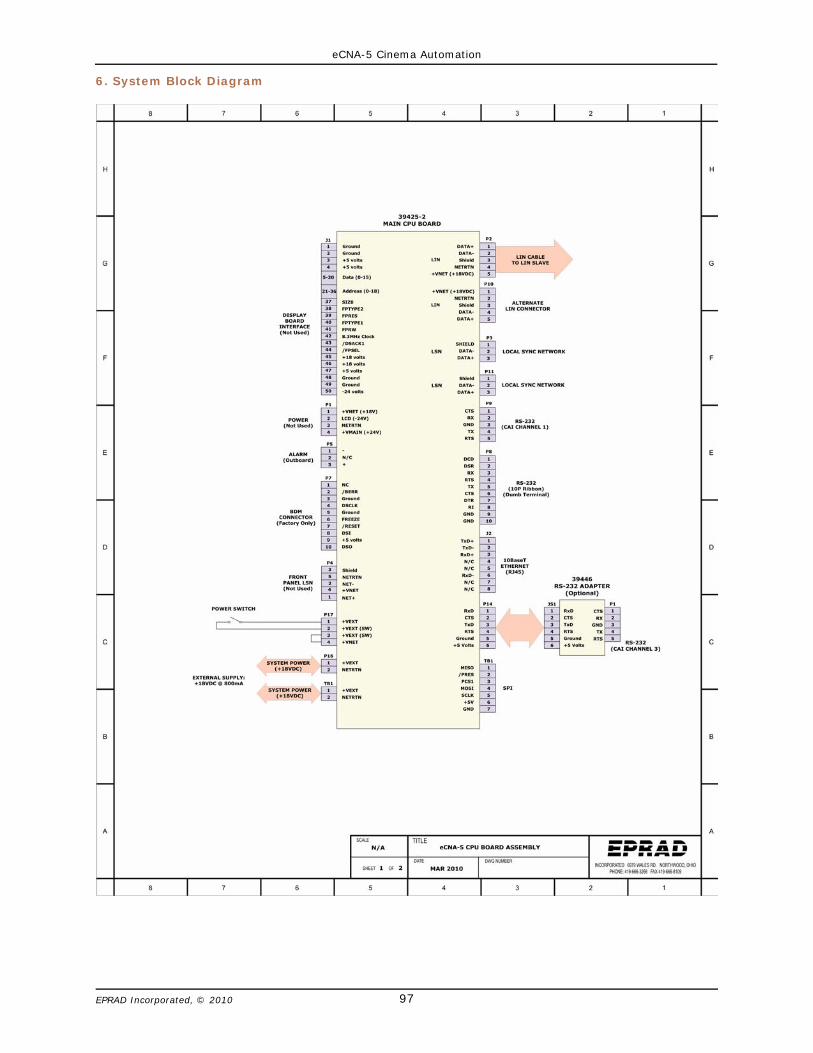
eCNA-5 Cinema Automation
97EPRAD Incorporated, © 2010
6. System Block Diagram
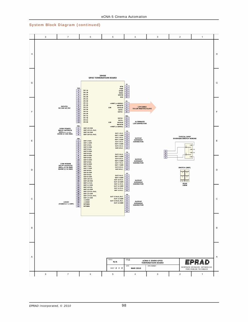
eCNA-5 Cinema Automation
98EPRAD Incorporated, © 2010
System Block Diagram (continued)

eCNA-5 Cinema Automation
99EPRAD Incorporated, © 2010
7. I/O Termination Board
The eCNA-5 39490 termination board is powered and controlled by the eCNA-10 main control boardvia the Local I/O Network (LIN). This is where all digital inputs and outputs are terminated in the field.The eCNA-5 can support up to two 39490 termination boards.
Features
• 14 low power relay outputs with LED indicators• 2 high power relay outputs with LED indicators• 8 optically isolated inputs• 12 volt DC power • Manual override headers
7.1 39490 GPIO Termination Board
1) Power LED - This indicates the status of the regulated +12 volt DC power.
2) Option Jumpers - These jumpers are used for special configuration.
Jumper Position Description
OPT 1 1-22-3 Undefined. Reserved for future.
OPT 2 1-22-3 Undefined. Reserved for future.
OPT 3 1-22-3 Undefined. Reserved for future.
OPT 4 1-22-3
Board #1 (LIN Id = 17)Board #2 (LIN Id = 18)

eCNA-5 Cinema Automation
100EPRAD Incorporated, © 2010
3) Status LED - This indicates the status of the on-board computer. If the computer is operatingproperly, it will indicate one of three conditions.
1: A fast (.2 second) blink rate indicates the computer is working and communicating properlywith the eCNA-5 main control board.
2: A slow (1 blink ON, 2 seconds OFF) rate indicates since power up, the board has notreceived data from the eCNA-5 main control board. The I/O is disabled.
3: A slow (2 blinks ON, 2 seconds OFF) rate indicates a communication timeout.Communications were once established and subsequently lost. The I/O is disabled.
4) Voltage/Contact Sense Jumpers - Inputs can be individually configured for either voltage senseor contact sense.
5) Inputs - TB5 (1-16) are the low voltage isolated input connections. Inputs can be wired foreither ‘contact’ or ‘voltage’ sense. All inputs are de-bounced and require a minimum pulse widthof 0.5 seconds.
Input Range: 5VDC - 34VDC, 3.6VRMS - 24VRMS @ 20mA Max.
6) 12 Volt Power Fuse - The 12VDC supply is fused at 1/2 amp. LED 19 indicates the condition ofthe fuse.
7) Optional Expansion Board - J1 socket strip is used for an expansion board.
8) 12 Volt Power Connections - TB4 (29-32) are the +12 volt power connections. This can be usedto power any 12 volt device such as an external relay.
9) Low Power Relay Outputs - TB4-1 through TB4-28 are the low power output connections. Allrelay contacts are ‘dry’ and require an external power source.
Contact Maximum Ratings: 30VRMS @ 2 Amps / 60VDC @ 1 Amp
10) High Power Relay Outputs - TB2 is the high power output connections. The relay contacts are‘dry’ and require and external power source.
Contact Maximum Ratings: 250VRMS @ 10 Amps / 30VDC @ 10 Amps
11) Override Connections - P3, P4, P5 and P6 headers are for the low power manual override cables.
12) LIN - TB1 and P1 are the LIN connections. This is the serial data and power connections fromthe main control board.
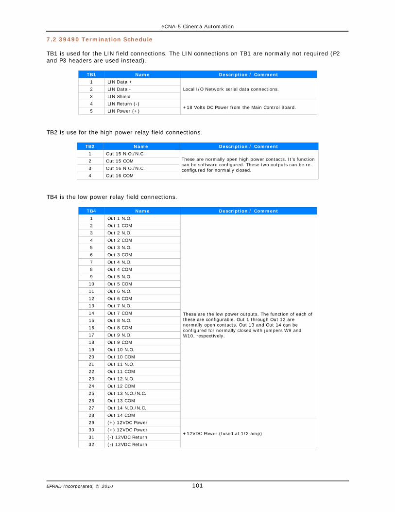
eCNA-5 Cinema Automation
101EPRAD Incorporated, © 2010
7.2 39490 Termination Schedule
TB1 is used for the LIN field connections. The LIN connections on TB1 are normally not required (P2and P3 headers are used instead).
TB1 Name Description / Comment
1 LIN Data +
Local I/O Network serial data connections.2 LIN Data -
3 LIN Shield
4 LIN Return (-)+18 Volts DC Power from the Main Control Board.
5 LIN Power (+)
TB2 is use for the high power relay field connections.
TB2 Name Description / Comment
1 Out 15 N.O./N.C.These are normally open high power contacts. It’s functioncan be software configured. These two outputs can be re-configured for normally closed.
2 Out 15 COM
3 Out 16 N.O./N.C.
4 Out 16 COM
TB4 is the low power relay field connections.
TB4 Name Description / Comment
1 Out 1 N.O.
These are the low power outputs. The function of each ofthese are configurable. Out 1 through Out 12 arenormally open contacts. Out 13 and Out 14 can beconfigured for normally closed with jumpers W9 andW10, respectively.
2 Out 1 COM
3 Out 2 N.O.
4 Out 2 COM
5 Out 3 N.O.
6 Out 3 COM
7 Out 4 N.O.
8 Out 4 COM
9 Out 5 N.O.
10 Out 5 COM
11 Out 6 N.O.
12 Out 6 COM
13 Out 7 N.O.
14 Out 7 COM
15 Out 8 N.O.
16 Out 8 COM
17 Out 9 N.O.
18 Out 9 COM
19 Out 10 N.O.
20 Out 10 COM
21 Out 11 N.O.
22 Out 11 COM
23 Out 12 N.O.
24 Out 12 COM
25 Out 13 N.O./N.C.
26 Out 13 COM
27 Out 14 N.O./N.C.
28 Out 14 COM
29 (+) 12VDC Power
+12VDC Power (fused at 1/2 amp)30 (+) 12VDC Power
31 (-) 12VDC Return
32 (-) 12VDC Return
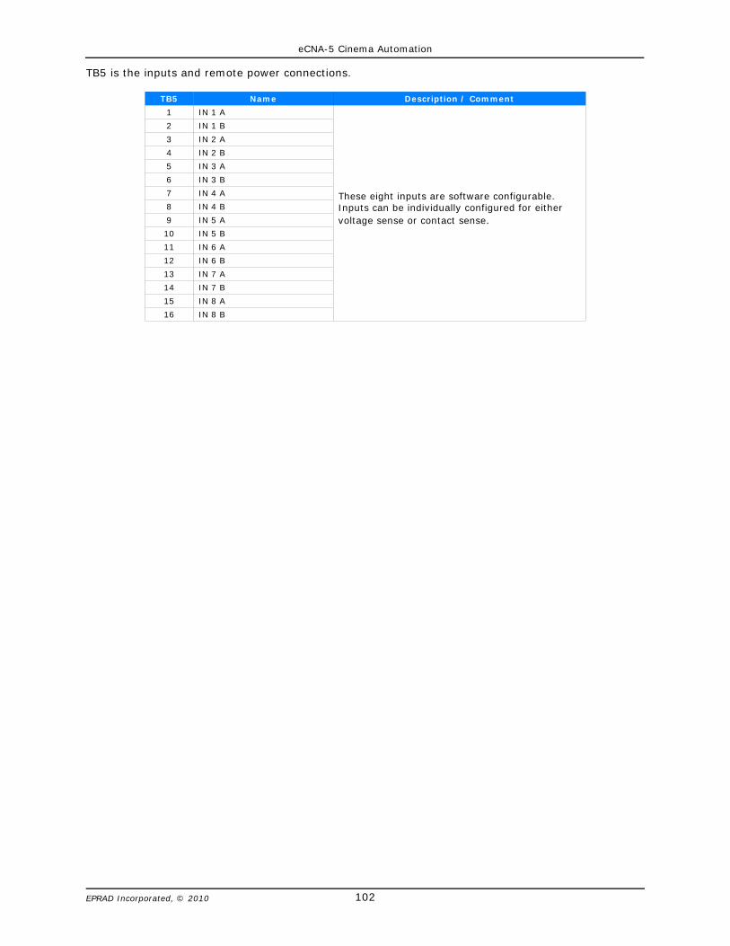
eCNA-5 Cinema Automation
102EPRAD Incorporated, © 2010
TB5 is the inputs and remote power connections.
TB5 Name Description / Comment
1 IN 1 A
These eight inputs are software configurable.Inputs can be individually configured for eithervoltage sense or contact sense.
2 IN 1 B
3 IN 2 A
4 IN 2 B
5 IN 3 A
6 IN 3 B
7 IN 4 A
8 IN 4 B
9 IN 5 A
10 IN 5 B
11 IN 6 A
12 IN 6 B
13 IN 7 A
14 IN 7 B
15 IN 8 A
16 IN 8 B
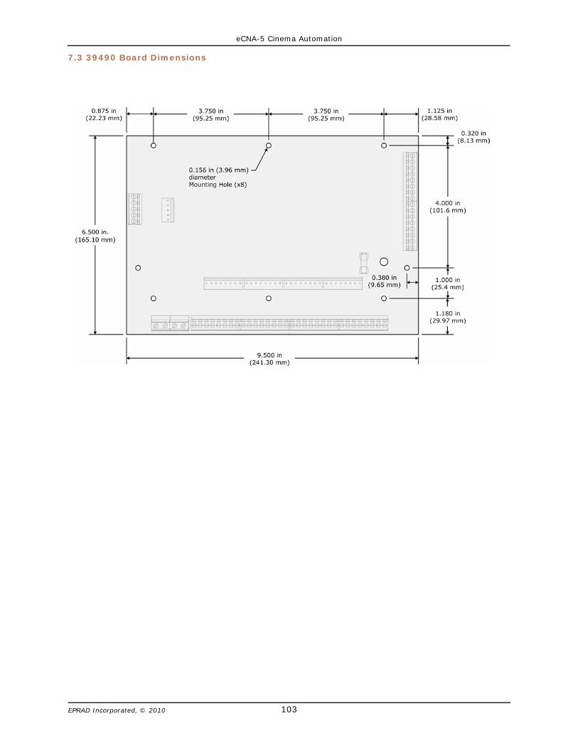
eCNA-5 Cinema Automation
103EPRAD Incorporated, © 2010
7.3 39490 Board Dimensions

eCNA-5 Cinema Automation
104EPRAD Incorporated, © 2010
7.4 Termination Board Inputs
All inputs are bi-directional. The figure below is a schematic representation of all inputs.
Inputs can be wired in a number of ways. Below are the most typical ways the inputs are wired to anexternal device.
Contact Sense Input
Using the +12 volt power source on the termination board, the input can wired for contact sensing.Only a remote relay contact or switch is required to generate an input.
Voltage Sense Input
The input can accept AC or DC voltage in the range of 5 to 24 volts. The maximum current draw perinput is 20 milliamps.
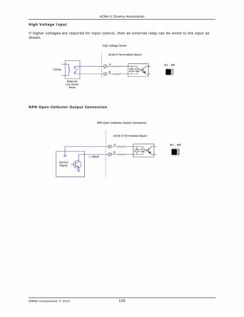
eCNA-5 Cinema Automation
105EPRAD Incorporated, © 2010
High Voltage Input
If higher voltages are required for input control, then an external relay can be wired to the input asshown.
NPN Open Collector Output Connection

eCNA-5 Cinema Automation
106EPRAD Incorporated, © 2010
7.5 Termination Board Outputs
All relay outputs are ‘dry’ contacts. They require an external power source. It is stronglyrecommended that the power source be current limited. The figure below is a schematicrepresentation of the relay outputs. Most outputs are normally open contacts.
Typical Masking motor wiring
eCNA-5 Cinema Automation
107EPRAD Incorporated, © 2010
8. Power Supply
The power requirements for the eCNA-5 control and I/O boards is 18 to 24 volts DC @ 0.8 A.
The wall plug power supply included with the eCNA-5 Rack and Panel mount is a 15 watt universal (90- 264 volt AC) input and a 18 volt DC @ 825mA output.
The power requirements for the Wall mount unit is 85 to 264 volts AC @ 0.25 A.