Embed Size (px)
Citation preview

Subject to change - Fabricio Dourado, Gernot Bauer - 02/2002 – Application Note 1MA49_0E
Products: CMU200, SMIQ
CMU200 BluetoothTM
Transmitter Measurementswithout Connection Setup
This application note shows how to perform Bluetooth transmitter measurementswith the CMU200 in a reduced signaling mode, in which the protocol handshakebetween the Bluetooth Equipment Under Test, the EUT, and CMU200 isskipped. This additional CMU200 feature allows both more flexible and faster RFtesting of Bluetooth modules.
A step-by-step example with SMIQ demonstrates the principles and serves as areference for integrating this method in user-specific test strategies.

CMU200 Bluetooth(TM) Transmitter Measurements without connection setup
1MA49_0E 2 Rohde & Schwarz
1 Overview.................................................................................................3
2 Abbreviations.........................................................................................3
3 Principle of Operation ...........................................................................4
4 Configuration .........................................................................................5Equipment Under Test (EUT).............................................................5CMU200 .............................................................................................5
5 Transmitter Tests ..................................................................................6Hardware Test Setup for Reduced Signaling Mode ...........................6Settings for SMIQ as EUT ..................................................................7Settings for CMU200 ..........................................................................9Measurement Results of Transmitter Tests .....................................11
Test Object Power:......................................................................11Test Object Modulation: ..............................................................11
6 Working with SMIQ-K5........................................................................12Installing SMIQ-K5 Software .......................................................12User Interface of SMIQ-K5 Software...........................................12
7 Ordering Information...........................................................................15
CMU200 Bluetooth(TM) Transmitter Measurements without connection setup
1MA49_0E 3 Rohde & Schwarz
1 OverviewThe CMU200 in signaling mode can carry out the most importanttransmitter and receiver tests on Bluetooth devices in production, qualitymanagement, and development. Signaling mode requires a connectionsetup to synchronize the CMU with the Equipment Under Test (EUT).However in unsynchronized mode, the CMU200 can also carry out anumber of transmitter measurements. This additional CMU200 featureallows both more flexible and faster RF testing of Bluetooth modules.Unsynchronized mode without connection setup is presented in thisapplication note.
The transmitter measurements possible in unsynchronized mode are:
� POWER: nominal and leakage, as well as the graphical displayof the power versus bit curve
� MODULATION: frequency accuracy, frequency drift, maximum driftrate, and frequency deviation (average, minimum,maximum, and graphical result as a function of thebit)
These CMU200 measurements are performed in unsynchronized modethrough either manual operation or remote control. There are no MASTER-SLAVE roles in unsynchronized mode and both the EUT and the testermust be configured locally prior to the measurement.
Examples using an SMIQ signal generator simulating the Bluetooth EUTboth help demonstrate the principles and serve as the reference forintegrating this method in user-specific test strategies. The SMIQ has to beequipped with options SMIQB11, and SMIQB10 or SMIQB20. Winbatchsequences demonstrate the application through the IEC/IEEE-bus remotecontrol.
2 AbbreviationsBD_Address Bluetooth Device Address
EUT Equipment Under Test

CMU200 Bluetooth(TM) Transmitter Measurements without connection setup
1MA49_0E 4 Rohde & Schwarz
3 Principle of OperationCMU200 Bluetooth transmitter measurements without a connection setupare based on the CMU200 signaling mode with:
� source trigger configured as RF or IF Power
� local pre-configuration of the Bluetooth signal on both the EUT andthe CMU200 as required for each of the transmittermeasurements.
This mode is defined as REDUCED SIGNALING MODE for simplicity'ssake and common terminology across the supported CMU200 standards(e.g. GPRS). The difference from signaling mode is explained below.
In signaling mode (see fig. 1) the CMU first transmits an inquiry signal todetect connectable Bluetooth devices within its domain. From the list ofdevices, a target device is selected. The CMU transmits a signal tosynchronize and attempt a connection to the target device. After theconnection is established, the EUT is put into its internal test mode wheretransmitter and receiver tests can be performed provided that the test modehas been locally enabled. When switching between the variousmeasurements, signalling control commands are transmitted by CMU200 tore-configure the EUT for the next measurement to be performed; thisprocedure is skipped when performing measurements in reduced signalingmode.
Fig. 1: Test setup in signaling mode
In reduced signaling mode, both the EUT and the CMU200 must beconfigured by the operator or via remote control prior to eachmeasurement. Therefore CMU200 does not act as “Master” and the EUT isnot “Slave”.
Fig. 2: Test setup in reduced signaling mode

CMU200 Bluetooth(TM) Transmitter Measurements without connection setup
1MA49_0E 5 Rohde & Schwarz
4 Configuration
Equipment Under Test (EUT)Parameters required for both the CMU200 and the EUT configuration:
� Frequency
� Transmit power
� Packet type
� Access code (sync word must correspond to the CMU200 BD_Address)
� Payload length
� Payload data pattern
CMU200Step by step configuration:
� GROUP CONFIGURATION:
• Input level / max. manual level 5.0dB higher than EUT expected powerconsidering the coupling losses
• Source trigger as "RF Power" or "IF Power"
� CONNECTION CONTROL, tab SIGNALLING:
• Automatic connection control pop up "OFF"
� CONNECTION CONTROL, tab NETWORK, section MASTER SIGNALING:
• CMU200 BD_Address as coded in the synch word of the EUT'stransmitted signal
� CONNECTION CONTROL, tab NETWORK, section TEST MODE:
• Test scenario as transmitted by the EUT
• Test mode hop scheme as "Hopping Rx/Tx Single"
• Tx packet type as transmitted by the EUT
• Tx packet length as transmitted by the EUT
� CONNECTION CONTROL, tab RF:
• Coupling losses (RF Input 2 / Ext. Att. Input 2)
� Measurement menus POWER and MODULATION, soft-key CHANNEL:
• Measurement mode as "Single"
• Display channel/frequency as transmitted by the EUT
CMU200 Bluetooth(TM) Transmitter Measurements without connection setup
1MA49_0E 6 Rohde & Schwarz
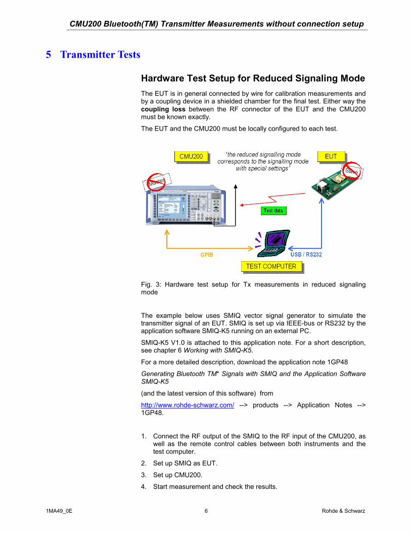
5 Transmitter Tests
Hardware Test Setup for Reduced Signaling ModeThe EUT is in general connected by wire for calibration measurements andby a coupling device in a shielded chamber for the final test. Either way thecoupling loss between the RF connector of the EUT and the CMU200must be known exactly.
The EUT and the CMU200 must be locally configured to each test.
Fig. 3: Hardware test setup for Tx measurements in reduced signalingmode
The example below uses SMIQ vector signal generator to simulate thetransmitter signal of an EUT. SMIQ is set up via IEEE-bus or RS232 by theapplication software SMIQ-K5 running on an external PC.
SMIQ-K5 V1.0 is attached to this application note. For a short description,see chapter 6 Working with SMIQ-K5.
For a more detailed description, download the application note 1GP48
Generating Bluetooth TM* Signals with SMIQ and the Application SoftwareSMIQ-K5
(and the latest version of this software) from
http://www.rohde-schwarz.com/ --> products --> Application Notes -->1GP48.
1. Connect the RF output of the SMIQ to the RF input of the CMU200, aswell as the remote control cables between both instruments and thetest computer.
2. Set up SMIQ as EUT.
3. Set up CMU200.
4. Start measurement and check the results.

CMU200 Bluetooth(TM) Transmitter Measurements without connection setup
1MA49_0E 7 Rohde & Schwarz
Settings for SMIQ as EUTStart the SMIQ-K5 program on your test computer to transfer suitabledata/control lists to SMIQ. At the top menu
1. Click 'Configure Packet'
2. Select Packet Type
3. Set Data Source to Standard
4. Click 'Packet Editor'
5. Enter the CMU200 Bluetooth Device Address for the Access Code of theEUT (SMIQ)
(The CMU200 default BD_Address is 1234 56 123456)

CMU200 Bluetooth(TM) Transmitter Measurements without connection setup
1MA49_0E 8 Rohde & Schwarz
6. Click 'PAYLOAD' and configure Length and Payload Data
With Pattern 1010 as payload, it is possible to perform all Tx measurements
7. Return to the top menu by clicking 'OK'
8. Click 'Transmission'
9. Enter a list name(e.g. 'DH1-1010')and click 'Transmit'
A data and a control list containing the modulation data for your Bluetoothpacket will be transfered to the SMIQ.
10. Exit SMIQ-K5

CMU200 Bluetooth(TM) Transmitter Measurements without connection setup
1MA49_0E 9 Rohde & Schwarz
Configure SMIQ manually to transmit the Bluetooth uplink signal:
11. Set FREQUENCY (e.g. 2.473GHz)SMIQ: SOUR:FREQ 2.473 GHZ
12. Set LEVEL (e.g. 0dBm)SMIQ: SOUR:POW 0.0 DBM
Settings for CMU2001. Select the function group BLUETOOTH, SIGNALLING
2. Configure GROUP CONFIGURATION:
• Set Input Level, Max. Level, Manual Level: 5dBm (5dB higherthan expected)CMUBT: LEV:MAX 5
• Set Trigger, Source (e.g. IF Power)CMUBT: TRIG:SOUR IFPower
3. Configure CONNECTION CONTROL by setting:
I. Signaling, automatic pop-up OFFGPIB command not applicable
II. Network, Master Signaling, CMU BD_Address (default 1234 56123456)CMUBT: CONF:NETW:PAG:TARG '123456123456'
III. Network, Test Mode, Test Scenario (e.g. Tx Test – 1010 Pattern)CMUBT: CONF:NETW:TMOD:SCEN P10;
IV. Network, Test Mode, Test Mode Hop Scheme: Hopping Rx/Tx onsingleCMUBT: CONF:NETW:TMOD:HSCH RXTX
V. Network, Test Mode, Transmitter Test, Packet Type (e.g. DH1)CMUBT: CONF:NETW:TMOD:TXT:PTYP DH1
VI. Network, Test Mode, Transmitter Test, Packet Length (e.g.27bytes)CMUBT: CONF:NETW:TMOD:TXT:LOTS 27
VII. RF, Ext. Att. Input (e.g. cable loss 1.0dB)CMUBT: INP RF2;:CORR:LOSS:INP2 1.0

CMU200 Bluetooth(TM) Transmitter Measurements without connection setup
1MA49_0E 10 Rohde & Schwarz
4. Configure MEASUREMENTS:
ESCAPE gets you from CONNECTION CONTROL to the last selectedMEASUREMENT window
I. Select the POWER measurement window
Configure POWER by pressing Power/Time twice:
• Control, Power/Time, Measure Mode: SingleCMUBT: CONF:POW:TIME:MMODE SING
• Control, Power/Time, Display Channel/Frequency (e.g.channel 71)CMUBT: CONF:POW:TIME:MFR:UNIT CH
CMUBT: CONF:POW:TIME:MFR 71
II. Select the MODULATION measurement window
Configure MODULATION by pressing Deviation/Time twice:
• Control, Modulation, Measure Mode: SingleCMUBT: CONF:MOD:DEV:MMODE SING
• Control, Modulation, Display Channel/Frequency (e.g. channel71)CMUBT: CONF:MOD:DEV:MFR:UNIT CH
CMUBT: CONF:MOD:DEV:MFR 71

CMU200 Bluetooth(TM) Transmitter Measurements without connection setup
1MA49_0E 11 Rohde & Schwarz
Measurement Results of Transmitter Tests
Test Object Power:
Fig. 4: Nominal-, Leakage-Power and Power versus TimeCMUBT: READ:POW:TIME?
Test Object Modulation:
Fig. 5: Frequency-Accuracy, -Drift, -Deviation, Maximum Drift Rateand Deviation versus Time
CMUBT: READ:MOD:DEV?
CMU200 Bluetooth(TM) Transmitter Measurements without connection setup
1MA49_0E 12 Rohde & Schwarz
6 Working with SMIQ-K5The SMIQ-K5 software can define a Bluetooth signal setup and transmit itto a SMIQ as a set of Data and Control Lists. The SMIQ can be configuredto use the content of this Data List as data source and the data sequence isthen modulated using Bluetooth modulation. The modulation parameterscan be changed, as well as parameters like power ramping, etc. Theseparameters either influence the calculation of the Data and Control Lists, orthey are transferred to the SMIQ directly by remote control commands.
The SMIQ-K5 helps to create Bluetooth compatible standard packets. DH1,DH3, DH5 and AUX1 packet types are supported. With the integratedpacket editor it is possible to edit every single information element of thepacket, whilst the software calculates defined elements like CRCs or SyncWords by itself.
Requirements to run SMIQ-K5:
• Windows 95/98, Windows NT or Windows 2000
• At least Intel x486 CPU with 32 MB RAM. Pentium or higherrecommended.
• GPIB-bus card PS-B4 from Rohde & Schwarz or an equivalent cardfrom National Instruments with installed Windows drivers is required. ARS232 connection can also be used if no GPIB interface is present.
• SMIQxB equipped with options B20 and B11. B12 is recommended if anon-truncated PRBS 15 is being used with DH1 packets.
• SMIQ-Z5 (extension Board) needed if any trigger output signals shallbe used.
Installing SMIQ-K5 SoftwareSMIQ-K5 V1.0 is attached to this application note as a windows self-expanding file (smiq_k5.exe). Download the latest version of the softwarefrom “http://www.rohde-schwarz.com/” --> products --> ApplicationNotes --> 1GP48.
. Install the software as follows:
1. Start smiq_k5.exe copying the setup files into a directory of your choice.The installation kit consists of 5 files: readme.txt, setup.exe, smiq-k5.001,smiq-k5.002 and smiq-k5.003
2. Start setup.exe and proceed in accordance with the dialog.
User Interface of SMIQ-K5 SoftwareAfter starting SMIQ-K5, the software is ready to create the Bluetoothcompatible packets. A detailed help function is available.

CMU200 Bluetooth(TM) Transmitter Measurements without connection setup
1MA49_0E 13 Rohde & Schwarz
The GPIB device address can be defined later when a connection to theSMIQ is needed, e.g. for transferring a set of data and control lists to theSMIQ.

CMU200 Bluetooth(TM) Transmitter Measurements without connection setup
1MA49_0E 14 Rohde & Schwarz
The GPIB/RS232 configuration window is available only after an attempt toconnect to an SMIQ.
A tentative to transmit data without selecting or defining a LIST NAME willresult in a ‘LIST Transmission Error’. A tentative to ‘Activate Lists’ withoutselecting or defining a LIST NAME will result in a ‘Data/Control List Error’.
The data transferred to SMIQ are data (DLIST) and control lists (CLIST).
The DLIST is organized in bits. The index counts the bit positions.
The CLIST is organized in symbols (the index counts symbol positions).The CLIST contains status changes.

CMU200 Bluetooth(TM) Transmitter Measurements without connection setup
1MA49_0E 15 Rohde & Schwarz
7 Ordering Information
Universal Radio Communication Tester CMU200:
CMU200 Base unit 1100.0008.02
Options:
CMU-B11 orCMU-B12
Reference Oscillator 1100.5000.02 or1100.5100.02
CMU-B21 Signalling unit 1100.5200.02CMU-B53 (factory installation only) Bluetooth extension 1100.5700.02CMU-K53 (factory installation only) Bluetooth test software 1115.5000.02CMU-U53 (B53/K53 upgrade) Bluetooth upgrade kit 1100.7302.02
Vector Signal Generator SMIQ:
SMIQ02B 300 kHz to 2.2 GHz 1125.5555.02SMIQ03B 300 kHz to 3.3 GHz 1125.5555.03SMIQ03B 300 kHz to 3.3 GHz 1125.5555.03SMIQ04B 300 kHz to 4.4 GHz 1125.5555.04SMIQ06B 300 kHz to 6.4 GHz 1125.5555.06
Options:
SMIQB11 Data Generator 1085.4502.04SMIQB12 Memory Extension 1085.2800.04SMIQB20 Modulation Coder 1125.5190.02
IEC/IEEE-Bus CardPS-B4 IEEE 488.2-Bus Interface 1006.6207.04
ROHDE & SCHWARZ GmbH & Co. KG . Mühldorfstraße 15 . D-81671 MünchenP.O.B 80 14 69 . D-81614 München . Telephone +41 89 4129 -0 · Fax +41 89 4129 - 3777 . Internet: www.rohde-schwarz.com