Embed Size (px)
Citation preview


CLP-4 VECTOR CALCULUS
Joel FELDMAN Andrew RECHNITZER Elyse YEAGER
THIS DOCUMENT WAS TYPESET ON TUESDAY 31ST AUGUST, 2021.

§§ Legal stuff
• Copyright c© 2017–21 Joel Feldman, Andrew Rechnitzer and Elyse Yeager.
• This work is licensed under the Creative Commons Attribution-NonCommercial-ShareAlike 4.0 International License. You can view a copy of the license athttp://creativecommons.org/licenses/by-nc-sa/4.0/.
• Links to the source files can be found at the text webpage
2

CONTENTS
1 Curves 11.1 Derivatives, Velocity, Etc. . . . . . . . . . . . . . . . . . . . . . . . . . . . . . . 71.2 Reparametrization . . . . . . . . . . . . . . . . . . . . . . . . . . . . . . . . . 181.3 Curvature . . . . . . . . . . . . . . . . . . . . . . . . . . . . . . . . . . . . . . 201.4 Curves in Three Dimensions . . . . . . . . . . . . . . . . . . . . . . . . . . . . 291.5 A Compendium of Curve Formula . . . . . . . . . . . . . . . . . . . . . . . . 351.6 Integrating Along a Curve . . . . . . . . . . . . . . . . . . . . . . . . . . . . . 361.7 Sliding on a Curve . . . . . . . . . . . . . . . . . . . . . . . . . . . . . . . . . 381.8 Optional — Polar Coordinates . . . . . . . . . . . . . . . . . . . . . . . . . . . 421.9 Optional — Central Forces . . . . . . . . . . . . . . . . . . . . . . . . . . . . . 471.10 Optional — Planetary Motion . . . . . . . . . . . . . . . . . . . . . . . . . . . 491.11 Optional — The Astroid . . . . . . . . . . . . . . . . . . . . . . . . . . . . . . 521.12 Optional — Parametrizing Circles . . . . . . . . . . . . . . . . . . . . . . . . 54
2 Vector Fields 572.1 Definitions and First Examples . . . . . . . . . . . . . . . . . . . . . . . . . . 572.2 Optional — Field Lines . . . . . . . . . . . . . . . . . . . . . . . . . . . . . . . 65
2.2.1 More about r1(t)ˆ v(r(t)) = 0 . . . . . . . . . . . . . . . . . . . . . . 712.3 Conservative Vector Fields . . . . . . . . . . . . . . . . . . . . . . . . . . . . . 732.4 Line Integrals . . . . . . . . . . . . . . . . . . . . . . . . . . . . . . . . . . . . 85
2.4.1 Path Independence . . . . . . . . . . . . . . . . . . . . . . . . . . . . . 902.5 Optional — The Pendulum . . . . . . . . . . . . . . . . . . . . . . . . . . . . 94
3 Surface Integrals 973.1 Parametrized Surfaces . . . . . . . . . . . . . . . . . . . . . . . . . . . . . . . 973.2 Tangent Planes . . . . . . . . . . . . . . . . . . . . . . . . . . . . . . . . . . . . 1073.3 Surface Integrals . . . . . . . . . . . . . . . . . . . . . . . . . . . . . . . . . . . 113
3.3.1 Parametrized Surfaces . . . . . . . . . . . . . . . . . . . . . . . . . . . 1133.3.2 Graphs . . . . . . . . . . . . . . . . . . . . . . . . . . . . . . . . . . . . 1153.3.3 Surfaces Given by Implicit Equations . . . . . . . . . . . . . . . . . . 1173.3.4 Examples of
ťS ρ dS . . . . . . . . . . . . . . . . . . . . . . . . . . . . 118
i

CONTENTS CONTENTS
3.3.5 Optional — Dropping Higher Order Terms in du, dv . . . . . . . . . 1303.4 Interpretation of Flux Integrals . . . . . . . . . . . . . . . . . . . . . . . . . . 132
3.4.1 Examples of Flux Integrals . . . . . . . . . . . . . . . . . . . . . . . . 1333.5 Orientation of Surfaces . . . . . . . . . . . . . . . . . . . . . . . . . . . . . . . 141
4 Integral Theorems 1464.1 Gradient, Divergence and Curl . . . . . . . . . . . . . . . . . . . . . . . . . . 146
4.1.1 Vector Identities . . . . . . . . . . . . . . . . . . . . . . . . . . . . . . . 1484.1.2 Vector Potentials . . . . . . . . . . . . . . . . . . . . . . . . . . . . . . 1564.1.3 Interpretation of the Gradient . . . . . . . . . . . . . . . . . . . . . . . 1614.1.4 Interpretation of the Divergence . . . . . . . . . . . . . . . . . . . . . 1624.1.5 Interpretation of the Curl . . . . . . . . . . . . . . . . . . . . . . . . . 166
4.2 The Divergence Theorem . . . . . . . . . . . . . . . . . . . . . . . . . . . . . . 1724.2.1 Optional — An Application of the Divergence Theorem — the Heat
Equation . . . . . . . . . . . . . . . . . . . . . . . . . . . . . . . . . . . 1814.2.2 Variations of the Divergence Theorem . . . . . . . . . . . . . . . . . . 1854.2.3 An Application of the Divergence Theorem — Buoyancy . . . . . . . 1874.2.4 Optional — Torque . . . . . . . . . . . . . . . . . . . . . . . . . . . . . 1914.2.5 Optional — Solving Poisson’s Equation . . . . . . . . . . . . . . . . . 195
4.3 Green’s Theorem . . . . . . . . . . . . . . . . . . . . . . . . . . . . . . . . . . 1984.4 Stokes’ Theorem . . . . . . . . . . . . . . . . . . . . . . . . . . . . . . . . . . . 209
4.4.1 The Interpretation of Div and Curl Revisited . . . . . . . . . . . . . . 2284.4.2 Optional — An Application of Stokes’ Theorem — Faraday’s Law . 230
4.5 Optional — Which Vector Fields Obey∇∇∇ˆ F = 0 . . . . . . . . . . . . . . . . 2314.6 Optional — More Interpretation of Div and Curl . . . . . . . . . . . . . . . . 2394.7 Optional — A Generalized Stokes’ Theorem . . . . . . . . . . . . . . . . . . . 248
A Trigonometry 261A.1 Trigonometry — Graphs . . . . . . . . . . . . . . . . . . . . . . . . . . . . . . 261A.2 Trigonometry — Special Triangles . . . . . . . . . . . . . . . . . . . . . . . . 261A.3 Trigonometry — Simple Identities . . . . . . . . . . . . . . . . . . . . . . . . 262A.4 Trigonometry — Add and Subtract Angles . . . . . . . . . . . . . . . . . . . 263A.5 Inverse Trigonometric Functions . . . . . . . . . . . . . . . . . . . . . . . . . 264
B Powers and Logarithms 266B.1 Powers . . . . . . . . . . . . . . . . . . . . . . . . . . . . . . . . . . . . . . . . 266B.2 Logarithms . . . . . . . . . . . . . . . . . . . . . . . . . . . . . . . . . . . . . . 267
C Table of Derivatives 269
D Table of Integrals 271
E Table of Taylor Expansions 273
F 3d Coordinate Systems 275F.1 Cartesian Coordinates . . . . . . . . . . . . . . . . . . . . . . . . . . . . . . . 275F.2 Cylindrical Coordinates . . . . . . . . . . . . . . . . . . . . . . . . . . . . . . 276F.3 Spherical Coordinates . . . . . . . . . . . . . . . . . . . . . . . . . . . . . . . 277
ii

CONTENTS CONTENTS
G ISO Coordinate System Notation 280G.1 Polar Coordinates . . . . . . . . . . . . . . . . . . . . . . . . . . . . . . . . . . 280G.2 Cylindrical Coordinates . . . . . . . . . . . . . . . . . . . . . . . . . . . . . . 282G.3 Spherical Coordinates . . . . . . . . . . . . . . . . . . . . . . . . . . . . . . . 283
H Conic Sections and Quadric Surfaces 287
I Review of Linear Ordinary Differential Equations 290
iii

CONTENTS CONTENTS
iv

CURVES
Chapter 1
We are now going to study vector-valued functions of one real variable. That is, we aregoing to study functions that assign to each real number t (typically in some interval) avector1 r(t). For example
r(t) =(x(t), y(t), z(t)
)might be the position of a particle at time t. As t varies, r(t) sweeps out a curve.
r(0)
r(1)r(2)
While in some applications t will indeed be “time”, it does not have to be. It can be simplya parameter that is used to label the different points on the curve that r(t) sweeps out. Wethen say that r(t) provides a parameterization of the curve.
Example 1.0.1(Parametrization of x2 + y2 = a2)
While we will often use t as the parameter in a parametrized curve r(t), there is no needto call it t. Sometimes it is natural to use a different name for the parameter. For example,consider the circle x2 + y2 = a2. It is natural to use the angle θ in the sketch below to labelthe point
(a cos θ , a sin θ
)on the circle.
1 We are going to use boldface letters, like r, to designate vectors. When writing by hand, it is clearer touse arrows, like~r, instead.
1

CURVES
x
y
x2 ` y2 “ a2
`a cos θ , a sin θ
˘
θ
That is,r(θ) =
(a cos θ , a sin θ
)0 ď θ ă 2π
is a parametrization of the circle x2 + y2 = a2. Just looking at the figure above, it is clearthat, as θ runs from 0 to 2π, r(θ) traces out the full circle.
However beware that just knowing that r(t) lies on a specified curve does not guaran-tee that, as t varies, r(t) covers the entire curve. For example, as t runs over the whole realline, 2
π arctan(t) runs over the interval (´1, 1). For all t,
r(t) =(x(t), y(t)
)= a
(2π
arctan(t) ,
c1´ 4
π2 arctan2(t)
)
is well-defined and obeys x(t)2 + y(t)2 = a2. But this r(t) does not cover the entire circlebecause y(t) is always positive.
Example 1.0.1
Example 1.0.2(Parametrization of (x´ h)2 + (y´ k)2 = a2)
We can tweak the parametrization of Example 1.0.1 to get a parametrization of the circleof radius a that is centred on (h, k). One way to do so is to redraw the sketch of Example1.0.1 with the circle translated so that its centre is at (h, k).
x
y
px ´ hq2 ` py ´ kq2 “ a2
a sin θa
ph, kq
`h ` a cos θ , k ` a sin θ
˘
θ
2

CURVES
We see from the sketch that
r(θ) =(h + a cos θ , k + a sin θ
)0 ď θ ă 2π
is a parametrization of the circle (x´ h)2 + (y´ k)2 = a2.A second way to come up with this parametrization is to observe that we can turn the
trig identity cos2 t + sin2 t = 1 into the equation (x´ h)2 + (y´ k)2 = a2 of the circle by
• multiplying the trig identity by a2 to get (a cos t)2 + (a sin t)2 = a2 and then
• setting a cos t = x ´ h and a sin t = y´ k , which turns (a cos t)2 + (a sin t)2 = a2
into (x´ h)2 + (y´ k)2 = a2.
Example 1.0.2
Example 1.0.3(
Parametrization of x2
a2 +y2
b2 = 1 and of x2/3 + y2/3 = a2/3)
We can build parametrizations of the curves x2
a2 +y2
b2 = 1 and x2/3 + y2/3 = a2/3 fromthe trig identity cos2 t + sin2 t = 1, like we did in the second part of the last example.
• Setting cos t = xa and sin t = y
b turns cos2 t + sin2 t = 1 into x2
a2 +y2
b2 = 1.
• Setting cos t =( x
a) 1
3 and sin t =( y
a) 1
3 turns cos2 t + sin2 t = 1 into x2/3
a2/3 +y2/3
a2/3 = 1.
So
r(t) =(a cos t , b sin t
)0 ď t ă 2π
r(t) =(a cos3 t , a sin3 t
)0 ď t ă 2π
give parametrizations of x2
a2 + y2
b2 = 1 and x2/3 + y2/3 = a2/3, respectively. To see thatrunning t from 0 to 2π runs r(t) once around the curve, look at the figures below.
x
y
x2
a2` y2
b2“ 1
t “ 0t “ π
t “ π2
t “ 3π2
x
y
x2/3 + y2/3 = a2/3
t = 0t = π
t = π/2
t = 3π/2
3

CURVES
The curve x2/3 + y2/3 = a2/3 is called an astroid. From its equation, we would expectits sketch to look like a deformed circle. But it is probably not so obvious that it wouldhave the pointy bits of the right hand figure. We will not explain here why they arise.The astroid is studied in some detail in Example 1.1.9. In particular, the above sketch iscarefully developed there.
Example 1.0.3
Example 1.0.4(Parametrization of ey = 1 + x2)
A very easy method that can often create parametrizations for a curve is to use x ory as a parameter. Because we can solve ey = 1 + x2 for y as a function of x, namelyy = ln
(1 + x2), we can use x as the parameter simply by setting t = x. This gives the
parametrizationr(t) =
(t , ln(1 + t2)
) ´8 ă t ă 8
Example 1.0.4
Example 1.0.5(Parametrization of x2 + y2 = a2, again
)It is also quite common that one can use either x or y to parametrize part of, but all of, acurve. A simple example is the circle x2 + y2 = a2. For each ´a ă x ă a, there are twopoints on the circle with that value of x. So one cannot use x to parametrize the wholecircle. Similarly, for each ´a ă y ă a, there are two points on the circle with that value ofy. So one cannot use y to parametrize the whole circle. On the other hand
r(t) =(t ,
aa2 ´ t2
) ´a ă t ă a
r(t) =(t , ´
aa2 ´ t2
) ´a ă t ă a
provide parametrizations of the top half and bottom half, respectively, of the circle usingx as the parameter, and
r(t) =(a
a2 ´ t2 , t) ´a ă t ă a
r(t) =(´a
a2 ´ t2 , t) ´a ă t ă a
provide parametrizations of the right half and left half, respectively, of the circle using yas the parameter.
Example 1.0.5
Example 1.0.6 (Unparametrization of r(t) = (cos t, 7´ t))
In this example, we will undo the parametrization r(t) = (cos t, 7´ t) and find the Carte-sian equation of the curve in question. We may rewrite the parametrization as
x = cos ty = 7´ t
4

CURVES
Note that we can eliminate the parameter t simply by using the second equation to solvefor t as a function of y. Namely t = 7´ y. Substituting this into the first equation gives usthe Cartesian equation
x = cos(7´ y)
Example 1.0.6
Curves often arise as the intersection of two surfaces. For example, the intersection
of the ellipsoid x2 + y2
2 + z2
3 = 1 with the paraboloid z = x2 + 2y2 is the blue curve inthe figure below. One way to parametrize such curves is to choose one of the three
x2 ` y2
2` z2
3“ 1
z “ x2 ` 2y2
coordinates x, y, z as the parameter, and solve the two given equations for the remainingtwo coordinates, as functions of the parameter. Here are two examples.
Example 1.0.7
The set of all (x, y, z) obeying
x3 ´ e3y = 0
x2 ´ ey + z = 0
is a curve. We can choose to use y as the parameter and think of
x3 = e3y
x2 + z = ey
as a system of two equations for the two unknowns x and z, with y being treated as agiven constant, rather than as an unknown. We can now solve the first equation for x,substitute the result into the second equation, and finally solve for z.
x3 = e3y ùñ x = ey
x2 + z = ey ùñ e2y + z = ey ùñ z = ey ´ e2y
5

CURVES
Sor(y) =
(ey , y , ey ´ e2y)
is a parametrization for the given curve.
Example 1.0.7
Example 1.0.8
The previous example was rigged so that it was easy to solve for x and z as functions of y.In practice it is not always easy, or even possible, to do so. A more realistic example is theset of all (x, y, z) obeying
x2 +y2
2+
z2
3= 1
x2 + 2y2 = z
which is the blue curve in the figure above. Substituting x2 = z ´ 2y2 (from the secondequation) into the first equation gives
´32
y2 + z +z2
3= 1
or, completing the square,
´32
y2 +13
(z +
32
)2=
74
If, for example, we are interested in points (x, y, z) on the curve with y ě 0, this can besolved to give y as a function of z.
y =
c29
(z +
32
)2´ 14
12
Then x2 = z´ 2y2 also gives x as a function of z. If x ě 0,
x =
cz´ 4
9
(z +
32
)2+
146
=
c43´ 4
9z2 ´ 1
3z
The other signs of x and y can be gotten by using the appropriate square roots. In thisexample, (x, y, z) is on the curve, i.e. satisfies the two original equations, if and only if allof (˘x,˘y, z) are also on the curve.
Example 1.0.8
6

CURVES 1.1 DERIVATIVES, VELOCITY, ETC.
1.1IJ Derivatives, Velocity, Etc.
This being a Calculus text, one of our main operations is differentiation. We are nowinterested in parametrizations r(t). It is very easy and natural to extend our definition ofderivative to r(t) as follows.
The derivative of the vector valued function r(t) is defined to be
r1(t) =drdt
(t) = limhÑ0
r(t + h)´ r(t)h
rptq
rpt ` hq
rpt ` hq ´ rptq
when the limit exists. In particular, if r(t) =(x(t) , y(t) , z(t)
), then
r1(t) =(x1(t) , y1(t) , z1(t)
)That is, to differentiate a vector valued function of t, just differentiate each of itscomponents.
Definition 1.1.1.
And of course differentiation interacts with arithmetic operations, like addition, in theobvious way. Only a little more thought is required to see that differentiation interactsquite nicely with dot and cross products too. Here are some examples.
Example 1.1.2
Let
a(t) = t2 ııı + t4 + t6 k
b(t) = e´t ııı + e´3t + e´5t k
γ(t) = t2
s(t) = sin t
We are about to compute some derivatives. To make it easier to follow what is going on,we’ll use some colour. When we apply the product rule
ddt[
f (t) g(t)]= f 1(t) g(t) + f (t) g1(t)
we’ll use blue to highlight the factors f 1(t) and g1(t). Here we go.
γ(t) b(t) = t2e´t ııı + t2e´3t + t2e´5t k
ùñ ddt[γ(t)b(t)
]=[2te´t´t2e´t]ııı + [2te´3t´3t2e´3t] + [2te´5t´5t2e´5t]k
= 2t
e´t ııı + e´3t + e´5t k(+ t2 ´ e´t ııı´ 3e´3t ´ 5e´5t k
(
= γ1(t)b(t) + γ(t)b1(t)
7

CURVES 1.1 DERIVATIVES, VELOCITY, ETC.
and
a(t) ¨ b(t) = t2e´t + t4e´3t + t6e´5t
ùñ ddt[a(t) ¨ b(t)] = [2te´t´t2e´t]+ [4t3e´3t´3t4e´3t]+ [6t5e´5t´5t6e´5t]
=[2te´t + 4t3e´3t + 6t5e´5t]+ [´t2e´t´3t4e´3t´5t6e´5t]
=
2t ııı + 4t3 + 6t5 k( ¨ e´t ııı + e´3t + e´5t k
(
+
t2 ııı + t4 + t6 k( ¨ ´ e´t ııı´ 3e´3t ´ 5e´5t k
(
= a1(t) ¨ b(t) + a(t) ¨ b1(t)
and
a(t)ˆ b(t) = det
ııı kt2 t4 t6
e´t e´3t e´5t
= ııı(t4e´5t ´ t6e´3t)´ (t2e´5t ´ t6e´t) + k(t2e´3t ´ t4e´t)
ùñ ddt[a(t)ˆ b(t)
]= ııı
(4t3e´5t ´ 6t5e´3t) ´ ( 2te´5t ´ 6t5e´t) + k( 2te´3t ´ 4t3e´t)
+ ııı(´5t4e´5t+3t6e´3t)´ (´5t2e´5t+t6e´t) + k(´3t2e´3t+t4e´t)
=
2t ııı + 4t3 + 6t5 k(ˆ
e´t ııı + e´3t + e´5t k(
+
t2 ııı + t4 + t6 k(ˆ ´ e´t ııı´ 3e´3t ´ 5e´5t k
(
= a1(t)ˆ b(t) + a(t)ˆ b1(t)
and
a(s(t)
)= (sin t)2 ııı + (sin t)4 + (sin t)6 k
ùñ ddt[a(s(t)
)]= 2(sin t) cos t ııı + 4(sin t)3 cos t + 6(sin t)5 cos t k
=
2(sin t) ııı + 4(sin t)3 + 6(sin t)5k(
cos t
= a1(s(t)
)s1(t)
Example 1.1.2
Of course these examples extend to general (differentiable) a(t), b(t), γ(t) and s(t) andgive us (most of) the following theorem.
8

CURVES 1.1 DERIVATIVES, VELOCITY, ETC.
Let
˝ a(t), b(t) be vector valued differentiable functions of t P R that take valuesin Rn and
˝ α, β P R be constants and˝ γ(t) and s(t) be real valued differentiable functions of t P R
Then
(a)ddt[α a(t) + β b(t)
]= α a1(t) + β b1(t) (linear combination)
(b)ddt[γ(t)b(t)
]= γ1(t)b(t) + γ(t)b1(t) (multiplication by scalar function)
(c)ddt[a(t) ¨ b(t)] = a1(t) ¨ b(t) + a(t) ¨ b1(t) (dot product)
(d)ddt[a(t)ˆ b(t)
]= a1(t)ˆ b(t) + a(t)ˆ b1(t) (cross product)
(e)ddt[a(s(t)
)]= a1
(s(t)
)s1(t) (composition)
Theorem 1.1.3 (Arithmetic of differentiation).
Let’s think about the geometric significance of r1(t). In particular, let’s think about therelationship between r1(t) and distances along the curve. The derivative r1(t) is the limitof r(t+h)´r(t)
h as h Ñ 0. The numerator, r(t + h)´ r(t), is the vector with head at r(t + h)and tail at r(t).
r(t)
r(t+ h)
r(t+ h)− r(t) ≈ r′(t) h
When h is very small this vector
˝ has the essentially the same direction as the tangent vector to the curve at r(t) and˝ has length being essentially the length of the part of the curve between r(t) and
r(t + h).
Taking the limit as h Ñ 0 yields that
˝ r1(t) is a tangent vector to the curve at r(t) that points in the direction of increasingt and
˝ if s(t) is the length of the part of the curve between r(0) and r(t), then dsdt (t) =
ˇdrdt (t)
ˇ.
This is worth stating formally.
9

CURVES 1.1 DERIVATIVES, VELOCITY, ETC.
Let r(t) be a parametrized curve.
(a) Denote by T(t) the unit tangent vector to the curve at r(t) pointing in thedirection of increasing t. If r1(t) ‰ 0 then
T(t) =r1(t)|r1(t)|
(b) Denote by s(t) the length of the part of the curve between r(0) and r(t). Then
dsdt
(t) =ˇˇdrdt
(t)ˇˇ
s(T)´ s(T0) =
ż T
T0
ˇˇdrdt
(t)ˇˇ dt
rp0q
rptqTptq
sptq
(c) In particular, if the parameter happens to be arc length, i.e. if t = s, so thatdsds = 1, then ˇ
ˇdrds
(s)ˇˇ = 1 T(s) = r1(s)
Lemma 1.1.4.
As an application, we have the
If r(t) =(x(t) , y(t) , z(t)
)is the position of a particle at time t, then
position at time t = r(t) =(x(t) , y(t) , z(t)
)velocity at time t = v(t) = r1(t) =
(x1(t) , y1(t) , z1(t)
)=
dsdt
(t) T(t)
speed at time t =dsdt
(t) = |v(t)| = |r1(t)| =b(x1(t)2 + y1(t)2 + z1(t)2
acceleration at time t = a(t) = r2(t) = v1(t) =(x2(t) , y2(t) , z2(t)
)and the distance travelled between times T0 and T is
s(T)´ s(T0) =
ż T
T0
ˇˇdrdt
(t)ˇˇdt =
ż T
T0
b(x1(t)2 + y1(t)2 + z1(t)2 dt
Lemma 1.1.5.
Note that the velocity v(t) = r1(t) is a vector quantity while the speed dsdt (t) = |r1(t)| is
a scalar quantity.
Example 1.1.6 (Circumference of a circle)
10

CURVES 1.1 DERIVATIVES, VELOCITY, ETC.
In general it can be quite difficult to compute arc lengths. So, as an easy warmup example,we will compute the circumference of the circle x2 + y2 = a2. We’ll also find a unit tangentto the circle at any point on the circle. We’ll use the parametrization
r(θ) =(a cos θ , a sin θ
)0 ď θ ď 2π
of Example 1.0.1. Using Lemma 1.1.4, but with the parameter t renamed to θ
r1(θ) = a(´ sin θ , cos θ
)T(θ) =
r1(θ)|r1(θ)| =
(´ sin θ , cos θ)
dsdθ
(θ) =ˇr1(θ)
ˇ= a
s(Θ)´ s(0) =ż Θ
0
ˇr1(θ)
ˇdθ = aΘ
As2 s(Θ) is the arc length of the part of the circle with 0 ď θ ď Θ, the circumference of thewhole circle is
s(2π) = 2πa
which is reassuring, since this formula has been known3 for thousands of years. The
x
y
x2 ` y2 “ a2
`a cos θ , a sin θ
˘
θ
Tpθq
formula s(Θ)´ s(0) = aΘ also makes sense — the part of the circle with 0 ď θ ď Θ is thefraction Θ
2π of the whole circle, and so should have length Θ2π ˆ 2πa. Also note that
r(θ) ¨ T(θ) = (a cos θ , a sin θ) ¨ (´ sin θ , cos θ
)= 0
so that the tangent to the circle at any point is perpendicular to the radius vector of thecircle at that point. This is another geometric fact that has been known4 for thousands ofyears.
2 You might guess that Θ is a capital Greek theta. You’d be right.3 The earliest known written approximations of π, in Egypt and Babylon, date from 1900–1600BC. The
first recorded algorithm for rigorously evaluating π was developed by Archimedes around 250 BC. Thefirst use of the symbol π, for the ratio between the circumference of a circle and its diameter, in printwas in 1706 by William Jones.
4 It is Proposition 18 in Book 3 of Euclid’s Elements. It was published around 300BC.
11

CURVES 1.1 DERIVATIVES, VELOCITY, ETC.
Example 1.1.6
Example 1.1.7 (Arc length of a helix)
Consider the curver(t) = 6 sin(2t)ııı + 6 cos(2t) + 5tk
where the standard basis vectors ııı = (1, 0, 0), = (0, 1, 0) and k = (0, 0, 1). We’ll firstsketch it, by observing that
˝ x(t) = 6 sin(2t) and y(t) = 6 cos(2t) obey x(t)2 + y(t)2 = 36 sin2(2t)+ 36 cos2(2t) =36. So all points of the curve lie on the cylinder x2 + y2 = 36 and
˝ as t increases,(x(t), y(t)
)runs clockwise around the circle x2 + y2 = 36 and at the
same time z(t) = 5t just increases linearly.
Our curve is the helix
y
z
x
t “ 0
t “ π2
t “ π
We have marked three points of the curve on the above sketch. The first has t = 0 and is0ııı + 6 + 0k. The second has t = π
2 and is 0ııı´ 6 + 5π2 k, and the third has t = π and is
0ııı + 6 + 5πk. We’ll now use Lemma 1.1.4 to find a unit tangent T(t) to the curve at r(t)and also the arclength of the part of curve between t = 0 and t = π.
r(t) = 6 sin(2t)ııı + 6 cos(2t) + 5tk
r1(t) = 12 cos(2t)ııı´ 12 sin(2t) + 5kdsdt
(t) =ˇr1(t)
ˇ=
b122 cos2(2t) + 122 sin2(2t) + 52 =
a122 + 52
= 13
T(t) =r1(t)|r1(t))| =
1213
cos(2t)ııı´ 1213
sin(2t) +5
13k
s(π)´ s(0) =ż π
0
ˇr1(t)
ˇdt = 13π
12

CURVES 1.1 DERIVATIVES, VELOCITY, ETC.
Example 1.1.7
Example 1.1.8 (Velocity and acceleration)
Imagine that, at time t, a particle is at
r(t) =[
h + a cos(
2πtT
)]ııı +[
k + a sin(
2πtT
)]
As |r(t) ´ h ııı ´ k | = a, the particle is running around the circle of radius a centred on(h, k). When t increases by T, the argument, 2π t
T , of cos(2π t
T)
and sin(2π t
T)
increasesby exactly 2π and the particle runs exactly once around the circle. In particular, it travelsa distance 2πa. So it is moving at speed 2πa
T . According to Lemma 1.1.5, it has
velocity = r1(t) = ´2πaT
sin(
2πtT
)ııı +
2πaT
cos(
2πtT
)
speed =dsdt
(t) = |r1(t)| = 2πaT
acceleration = r2(t) = ´4π2aT2 cos
(2π
tT
)ııı´ 4π2a
T2 sin(
2πtT
) = ´4π2
T2
[r(t)´ h ııı´ k
]Here are some observations.
• The velocity r1(t) has dot product zero with r(t)´ h ııı´ k , which is the radius vectorfrom the centre of the circle to the particle. So the velocity is perpendicular to theradius vector, and hence parallel to the tangent vector of the circle at r(t).
• The speed given by Lemma 1.1.5 is exactly the speed we found above, just before westarted applying Lemma 1.1.5.
• The acceleration r2(t) points in the direction opposite to the radius vector.
x
y
rptqr1ptq
r2ptq
ph, kq
13

CURVES 1.1 DERIVATIVES, VELOCITY, ETC.
Example 1.1.8
Example 1.1.9 (Perimeter of the astroid)
In this example, we find the perimeter of the astroid5
x2/3 + y2/3 = a2/3
A geometric construction of this curve, as well as a derivation of its equation is given inthe optional section 1.11 later. We’ll start by finding a convenient parametrization.
˝ To do so, notice that x2/3 + y2/3 = a2/3 looks somewhat like the equation of the circlex2 + y2 = a2.
˝ The standard parametrization of the circle, namely x = a cos t, y = a sin t worksbecause of the elementary trig identity cos2 t + sin2 t = 1.
˝ If we can arrange that x(t)2/3 = a2/3 cos2 t and y(t)2/3 = a2/3 sin2 t, then the sameelementary trig identity will give x(t)2/3 + y(t)2/3 = a2/3, as desired.
˝ But of course its easy to arrange that: just solve x(t)2/3 = a2/3 cos2 t for x(t), namelyx(t) = a cos3 t, and solve y(t)2/3 = a2/3 sin2 t for y(t), namely y(t) = a sin3 t.
Our parametrization isr(t) = a cos3 t ııı + a sin3 t
By Lemma 1.1.4
r(t) = a cos3 t ııı + a sin3 t
r1(t) = ´3a sin t cos2 t ııı + 3a sin2 t cos t
dsdt
(t) =ˇr1(t)
ˇ=
a9a2 sin2 t cos4 t + 9a2 sin4 t cos2 t
= 3ab
sin2 t cos2 t(cos2 t + sin2 t)
= 3aˇsin t cos t
ˇ
T(t) =r1(t)|r1(t))| =
sin t cos t| sin t cos t|
(´ cos t ııı + sin t )
= sgn(sin t cos t
) (´ cos t ııı + sin t )
Here sgn(sin t cos t
)means “the sign of sin t cos t”, i.e +1 when sin t cos t ą 0 and ´1
when sin t cos t ă 0. So
T(t) =
#1 if sin t ą 0, cos t ą 0 or sin t ă 0, cos t ă 0´1 if sin t ą 0, cos t ă 0 or sin t ă 0, cos t ą 0
+ (´ cos t ııı + sin t )
=
#1 if 0 ă t ă π
2 or π ă t ă 3π2
´1 if π2 ă t ă π or 3π
2 ă t ă 2π
+ (´ cos t ııı + sin t )
Before we go on to sketch the astroid and compute its perimeter, we can make a fewobservations that will simplify our lives.
5 Astroid should not be confused with asteroid, though both words derive from the Greek word for star.
14

CURVES 1.1 DERIVATIVES, VELOCITY, ETC.
˝ The signs of both components of r(t) are the same as the signs of the components ofcos t ııı + sin t ; and the signs of both components of r1(t) are the same as the signs ofthe components of ´ sin t ııı + cos t . Consequently the astroid looks somewhat like acircle in that
– when 0 ď t ď π2 , r(t) lies in the first quadrant and moves upward and to the
left as t increases and– when π
2 ď t ď π, r(t) lies in the second quadrant and moves downward and tothe left as t increases and
– when π ď t ď 3π2 , r(t) lies in the third quadrant and moves downward and to
the right as t increases and– when 3π
2 ď t ď 2π, r(t) lies in the fourth quadrant and moves upward and tothe right as t increases and
– r(2π) = r(0) so that the astroid is a closed curve that circumnavigates the originexactly once as t runs from 0 to 2π.
˝ Something weird happens at those values of t where sin t cos t changes sign6, i.e. att = 0, π
2 , π, 3π2 , etc. Namely T(t) flips. To be precise
limtÑ0´
T(t) = limtÑ0´
sgn(sin t cos t
)lim
tÑ0´
(´ cos t ııı + sin t )= ııı
limtÑ0+
T(t) = limtÑ0+
sgn(sin t cos t
)lim
tÑ0+
(´ cos t ııı + sin t )= ´ııı
and
limtÑπ/2´
T(t) = limtÑπ/2´
sgn(sin t cos t
)lim
tÑπ/2´
(´ cos t ııı + sin t )=
limtÑπ/2+
T(t) = limtÑπ/2+
sgn(sin t cos t
)lim
tÑπ/2+
(´ cos t ııı + sin t )= ´
and so on. This signals cusps in the curve at t = 0, i.e. at r(0) = aııı, and at t = π2 ,
i.e. at r(π2 ) = a, and so on. So while the astroid looks somewhat like a circle, it has
cusps at ˘aııı and ˘a. Here is the sketch.
x
y
x2/3 + y2/3 = a2/3
t = 0t = π
t = π/2
t = 3π/2
6 Like a cross-walk sign.
15

CURVES 1.1 DERIVATIVES, VELOCITY, ETC.
˝ The astroid is invariant under reflections in the x-axis and in the y-axis. That is,x2/3 + y2/3 = a2/3 is invariant under x Ñ ´x and also under y Ñ ´y. So to find thewhole perimeter, it suffices to find the arc length of the part of the astroid in the firstquadrant, and then multiply by 4.
perimeter = 4ż π/2
0
dsdt
dt = 4ż π/2
03a sin t cos t dt = 6a
ż π/2
0sin(2t) dt
= 6a[´ cos(2t)
2
]π/2
0= 6a
Example 1.1.9
Example 1.1.10 (r1(t) = 0)
In the last example, we found that the astroid had cusps at those points r(t) where the ve-locity r1(t) vanished. In this example, we will explore a little further what can happenwhen r1(t) = 0.
Suppose that you are out for a walk and that your position at time t is r(t). If at sometime you have nonzero velocity, it is very hard for you to change your direction of motiondiscontinuously7. On the other hand, when r1(t) = 0, you are not moving at all and it iseasy for you to turn and leave in any direction you choose. You could reverse directioncompletely, or make a sharp left turn, or not change direction at all. Here are examples ofall of these. They all have r1(t) = 0. They are sketched below.
r1(t) = (t5, t2) r11(t) = (5t4, 2t)
r2(t) =
#(t2, 0) if t ě 0(0, t2) if t ď 0
+r12(t) =
#(2t, 0) if t ě 0(0, 2t) if t ď 0
+
r3(t) = (t3, 0) r13(t) = (3t2, 0)
r1ptq
t “ 0
r2ptq
t “ 0
r3ptqt “ 0
Example 1.1.10
Example 1.1.11 (Corkscrew)
We’ll find the arc length of
r(t) = t cos t ııı + t sin t + t k 0 ď t ď?
2
7 For your velocity to jump discontinuously, your acceleration has to be infinite, which requires an infiniteforce. You might not look so healthy afterwards
16

CURVES 1.1 DERIVATIVES, VELOCITY, ETC.
We’ll first sketch it, by observing that
˝ x(t) = t cos t, y(t) = t sin t and z(t) = t obey x(t)2 + y(t)2 = t2 = z(t)2. So all pointsof the curve lie on the cone x2 + y2 = z2 and
˝ as t increases,(x(t), y(t)
)runs counterclockwise around a “circle whose radius in-
creases linearly with t and at the same time z(t) also increases linearly.
Our curve is the “corkscrew”
y
z
x
y “ z, x “ 0
By Lemma 1.1.4
r(t) = t cos t ııı + t sin t + t k
r1(t) = [cos t´ t sin t]ııı + [sin t + t cos t] + kdsdt
(t) =ˇr1(t)
ˇ
=b(
cos2 t´ 2t sin t cos t + t2 sin2 t)+(
sin2 t + 2t sin t cos t + t2 cos2 t)+ 1
=a
2 + t2
Our goal, stated at the beginning of this example, was to compute
s(?
2)´ s(0) =ż ?2
0
ˇr1(t)
ˇdt =
ż ?2
0
a2 + t2 dt
To evaluate the integral, we’ll use three techniques that you learned in your first integralcalculus course. First, motivated by the
?2 + t2, we’ll use the trigonometric substitution
t =?
2 tan u dt =?
2 sec2 u du 2 + t2 = 2[1 + tan2 u
]= 2 sec2 u
When t = 0, u = 0 and when t =?
2, tan u = 1 so that u = π4 and
s(?
2)´ s(0) =ż π/4
0
a2 sec2 u
?2 sec2 u du = 2
ż π/4
0sec3 u du
You may have evaluated this integral in first year. There are several ways of doing so.Perhaps the most straight forward, but also most tedious, method is to rewrite the integralas
s(?
2)´ s(0) = 2ż π/4
0
cos ucos4 u
du
17

CURVES 1.2 REPARAMETRIZATION
We recognize that this is a trigonometric integral that contains an odd power of cos u, sowe substitute w = sin u, dw = cos u du, cos2 u = 1´ w2. When u = 0, w = 0 and whenu = π
4 , w = 1?2
so that
s(?
2)´ s(0) = 2ż 1/
?2
0
dw
(1´w2)2
The integrand is now a rational function, i.e. a ratio of polynomials. So we apply partialfractions.
s(?
2)´ s(0) = 2ż 1/
?2
0
dw
[(1´w)(1 + w)]2
=12
ż 1/?
2
0
[ 11´w
+1
1 + w
]2dw
=12
ż 1/?
2
0
[ 1(1´w)2 +
2(1´w)(1 + w)
+1
(1 + w)2
]dw
=12
ż 1/?
2
0
[ 1(1´w)2 +
11´w
+1
1 + w+
1(1 + w)2
]dw
=12
[ 11´w
´ ln |1´w|+ ln |1 + w| ´ 11 + w
]1/?
2
0
=12
[ 2w1´w2 + ln
1 + w1´w
]1/?
2
0=
12
[2?
2 + ln?
2 + 1?2´ 1
]« 2.2956
Ooof!Example 1.1.11
1.2IJ Reparametrization
There are invariably many ways to parametrize a given curve. Kind of trivially, onecan always replace t by, for example, 3u. But there are also more substantial ways toreparametrize curves. It often pays to tailor the parametrization used to the application ofinterest. For example, we shall see in the next couple of sections that many curve formulaesimplify a lot when arc length is used as the parameter.
Example 1.2.1
Here are three different parametrizations of the semi-circle x2 + y2 = r2, y ě 0.
˝ The first uses the polar angle θ as the parameter. We have already seen, in Example1.0.1, the parametrization
x
y
x2 ` y2 “ r2
`r cos θ , r sin θ
˘
θ
r1(θ) =(r cos θ , r sin θ
)0 ď θ ď π
18

CURVES 1.2 REPARAMETRIZATION
˝ The second uses x as the parameter. Just solving x2 + y2 = r2, y ě 0 for y as afunction of x, gives y(x) =
?r2 ´ x2 and so gives the parametrization
x
y
x2 ` y2 “ r2
`x ,
?r2 ´ x2
˘x r2(x) =
(x ,
ar2 ´ x2
) ´ r ď x ď r
˝ The third uses arc length from (r, 0) as the parameter. We have seen, in Example1.1.6, that the arc length from (r, 0) to r1(θ) is just s = rθ. So the point on the semi-circle that is arc length s away from (r, 0) is
x
y
x2 ` y2 “ r2
`r cos s
r, r sin s
r
˘
sr3(s) = r1
( sr
)=(
r cossr
, r sinsr
)
with 0 ď s ď πr.
Example 1.2.1
We shall see that, for some purposes, it is convenient to use parametrization by arclength. Here is a messier example in which we reparametrize a curve so as to use the arclength as the parameter.
Example 1.2.2
We saw in Example 1.1.9, that, as t runs from 0 to π2 , r(t) = a cos3 t ııı + a sin3 t runs
from (a, 0) to (0, a) along the astroid x2/3 + y2/3 = a2/3. Suppose that we want a newparametrization R(s) chosen so that, as s runs from 0 to some appropriate value, R(s)runs from (a, 0) to (0, a) along x2/3 + y2/3 = a2/3, with s being the arc length from (a, 0)to R(s) along x2/3 + y2/3 = a2/3.
x
y
Rpsqrptq
s
19

CURVES 1.3 CURVATURE
We saw, in Example 1.1.9, that, for 0 ď t ď π2 , ds
dt = 3a2 sin(2t) so that the arclength from
(a, 0) = r(0) to r(t) is
s(t) =ż t
0
3a2
sin(2t1)dt1 =3a4[1´ cos(2t)
]which runs from 0, at t = 0, to 3a
2 , at t = π2 . This is relatively clean and we can invert s(t)
to find t as a function of s. The value, T(s), of t that corresponds to any given 0 ď s ď 3a2
is determined by
s =3a4[1´ cos
(2T(s)
)] ðñ T(s) =12
arccos(
1´ 4s3a
)and
R(s) = r(T(s)
)= a cos3 (T(s))ııı + a sin3 (T(s))
We can simplify cos3 (T(s)) and sin3 (T(s)) by just using trig identities to convert thecos
(2T(s)
)in s = 3a
4
[1´ cos
(2T(s)
)]into cos
(T(s)
)’s and sin
(T(s)
)’s.
s =3a4[1´ cos
(2T(s)
)]=
3a4[1´ (2 cos2 (T(s)´ 1
)] ðñ cos2 (T(s)) = 1´ 2s3a
s =3a4[1´ cos
(2T(s)
)]=
3a4[1´ (1´ 2 sin2 (T(s))] ðñ sin2 (T(s)) = 2s
3a
Consequently the desired parametrization is
R(s) = a[
1´ 2s3a
]3/2
ııı + a[
2s3a
]3/2
0 ď s ď 3a2
which is remarkably simple.
Example 1.2.2
1.3IJ Curvature
So far, when we have wanted to approximate a complicated curve by a simple curve nearsome point, we drew the tangent line to the curve at the point. That’s pretty crude. Inparticular tangent lines are straight — they don’t curve. We will get a much better ideaof what the complicated curve looks like if we approximate it, locally, by a very simple“curvy curve” rather than by a straight line. Probably the simplest “curvy curve” is acircle8 and that’s what we’ll use.
8 Circles are good for studying “curvature”, because, unlike parabolas for example, the rate at which acircle curves is uniform over the entire circle.
20

CURVES 1.3 CURVATURE
(a) The circle which best approximates a given curve near a given point is calledthe circle of curvature or the osculating circle9 at the point.
(b) The radius of the circle of curvature is called the radius of curvature at thepoint and is normally denoted ρ.
(c) The curvature at the point is κ = 1/ρ.
(d) The centre of the circle of curvature is called centre of curvature at the point.
Definition 1.3.1.
These definitions are illustrated in the figure below. It shows (part of) the osculating circleat the point P. The point C is the centre of curvature.
ρ
P
C
Note that when the curvature κ is large, the radius of curvature ρ is small and wehave a very curvy curve. On the other hand when the curvature κ is small, the radiusof curvature ρ is large and our curve is almost straight. In particular, straight lines havecurvature exactly zero.
We are now going to determine how to find the circle of curvature, starting by figuringout what its radius should be. We’ll first look at curves10 that lie in the xy-plane and thenmove on to curves in 3d. Consider the black curve in the figure below.
dθρ
ds
That figure also contains a (portion of a) red circle that fits the curve really well betweenthe two radial lines that are (a very small) angle dθ apart. So the arclength ds of the part
9 “Osculare” is the Latin verb “to kiss”. The German mathematician Gottfried Wilhelm (von) Leibniz(1646–1716) named the circle the “circulus osculans”.
10 We’ll also assume that the curves of interest are smooth, with no cusps for example, and not straight,so that the radius of curvature 0 ă ρ ă 8.
21

CURVES 1.3 CURVATURE
of the black curve between the two radial lines, should be (essentially) the same as thearc length of the circle between the two radial lines, which is ρ |dθ|, where ρ is the radiusof the circle. (We put in absolute values to take into account the possibility that dθ couldbe negative.) Thus ds = ρ |dθ|. When dθ is a macroscopic angle, this is of course anapproximation. But in the limit as dθ Ñ 0, we should end up with
ρ =
ˇˇdsdθ
ˇˇ
We now have a formula for the radius of curvature, but not in a very convenient form,because to evaluate it we would need to know the arc length along the curve as a functionof the angle θ in the rightmost figure below. We’ll now spend some time developing moreconvenient formulae for ρ. First consider the three figures below. They all show the samecurve as in the last figure. The leftmost figure just shows
˝ the curve of interest, which is the black curve, and˝ the (blue) point of interest on the black curve. We want to find the curvature at that
point.
The middle figure shows the same curve and point of interest and also shows
˝ the red circle of curvature (i.e. best fitting circle) for the black curve at the blue dot.˝ The red dot is the centre of curvature.
The rightmost figure shows the same black curve, blue point of interest and red circle ofcurvature (at least part of it) somewhat enlarged.
˝ The angle θ is the angle between ııı and the radius vector from the red dot (the centreof curvature) to the blue dot (the point of interest).
˝ T is the tangent vector to the black curve at the blue dot.˝ The angle φ is the angle between ııı and T. The vector T is also tangent to the red circle.
As the tangent and radius vectors for circles are perpendicular to each other11, wehave that φ = θ + π
2 and hence ρ =ˇds
dφ
ˇtoo.
T
θ
θ
φ ııı
ııı
We are now in a position to develop a bunch of formulae for the radius of curvature ρ andthe curvature κ = 1
ρ , that are more convenient than κ =ˇ ds
dφ
ˇ´1. These formulae will usethe
11 We saw that in Example 1.1.6.
22

CURVES 1.3 CURVATURE
If r(t) is a parametrized curve, then
• v(t) = drdt (t) is the velocity vector at r(t)
• a(t) = d2rdt2 (t) is the acceleration vector at r(t)
• T(t) is the unit tangent vector to the curve at r(t) that points in the directionof increasing t.
• N(t) is the unit normal vector to the curve at r(t) that points toward thecentre of curvature.
• κ(t) is the curvature at r(t)
• ρ(t) is the radius of curvature at r(t)
Notation 1.3.2.
(a) Given12 s(φ), i.e. if we know the arc length along the curve as a function ofthe angle13 φ = >(ııı, T), then
ρ =
ˇˇdsdφ
ˇˇ κ =
ˇˇdsdφ
ˇˇ´1
κ =
ˇˇdφ
ds
ˇˇ
(b) Given r(s), i.e. if we have a parametrization of the curve in terms of arclength, then
dTds
(s) = κ(s) N(s)
where N(s) is the unit normal vector to the curve at r(s) that points towardthe centre of curvature.
(c) Given r(t), i.e. if we have a general parametrized curve, then
dTdt
= κdsdt
N v(t) =dsdt
(t) T(t) a(t) =d2sdt2 T + κ
(dsdt
)2
N
(d) Given(x(t) , y(t)
), (for curves in the xy-plane)
κ =
ˇˇˇv(t)ˆ a(t)(ds
dt)3
ˇˇˇ =
ˇdxdt
d2ydt2 ´ dy
dtd2xdt2
ˇ
[(dxdt)2
+(dy
dt)2]3/2
Theorem 1.3.3.
12 The equation s = s(φ) is called the “intrinsic equation of the curve”.
23

CURVES 1.3 CURVATURE
(e) Given y(x), (again for curves in the xy-plane)
κ =
ˇd2ydx2
ˇ
[1 +
(dydx)2]3/2
Theorem 1.3.3 (continued).
Proof. (a) Given s(φ), then
ρ =ˇˇdsdφ
ˇˇ κ =
ˇˇdsdφ
ˇˇ´1
As we are assuming that 0 ă ρ =ˇˇ ds
dφ
ˇˇ ă 8, the inverse function theorem says that we can
invert the function s(φ) (at least locally) to get φ as a function of s, and that
κ =ˇˇdφ
ds
ˇˇ
(b) Given r(s), then, by Lemma 1.1.4.c, T(s) = r1(s) is a unit tangent to the curve at r(s)and
dTds
=dTdφ
dφ
ds(˚)
Now up to a sign dφds is κ, and just because φ = >(ııı, T), with T a unit vector,
T = cos φ ııı + sin φ
ùñ dTdφ
= ´ sin φ ııı + cos φ (˚˚)
So dTdφ is a unit vector that is perpendicular14 to T, and hence to the curve at r(s), and
dTds
(s) = κ(s) N(s) (:)
with N(s) a unit normal vector to the curve at r(s). In fact, N(s) is the unit normal vectorto the curve at r(s) that points toward the centre of curvature.
To see that, look at the figures below15, and note that substituting the sign informationfrom each figure into (˚) gives (:). For example, consider the figure on the lower left. In
13 The notation >(ııı, T) means “the angle between ııı and T”.14 Think about why this should be the case. In particular, sketch T and φ and think about what the sketch
says about dTdφ .
15 In each of the four figures, the arrow on the curve specifies the direction of increasing arc length s andthe red dot is the centre of curvature for the curve at the blue dot.
24

CURVES 1.3 CURVATURE
TdTdφ
φ
cosφ ą 0, dφds
ą 0
TdTdφ
φ
cosφ ą 0, dφds
ă 0
TdTdφ
φ
cosφ ă 0, dφds
ă 0
TdTdφ
φ
cosφ ă 0, dφds
ą 0
that figure,
˝ the x component of T is negative (T is leftward pointing in the figure),
˝ which makes cos φ negative (see (˚˚)),˝ which makes the y component of dT
dφ negative (see (˚˚) again),
˝ so dTdφ is downward pointing,
so dTdφ = ´N (the centre of curvature is the red dot above the curve) and
˝ as s increases (i.e. as you move in the direction of the arrow on the curve), φ de-creases (on the far right hand part of the curve φ « 3π
2 , while on the far left handpart of the curve φ « π), so dφ
ds ă 0 and κ =ˇdφ
ds
ˇ= ´dφ
ds .
˝ So by (˚), dTds = dT
dφdφds =
(´ N)(´κ) = κN.
In each of the three other figures we also end up with dTds = κ(s)N(s).
Note that if κ(s) = 0, then N(s) is not defined. This makes sense: if the curve is (locally) astraight line, there is no “best fitting circle”.
(c) Given r(t), i.e. if we have a general parametrized curve, we can determine a unittangent vector by using Lemma 1.1.4:
v(t) =drdt
(t) =dsdt
(t) T(t) ùñ T(t) =r1(t)|r1(t)|
Then we can determine κ and N by differentiating T(t) and using the chain rule:
dTdt
=dTds
dsdt
= κdsdt
N ùñ κ(t) =|T1(t)||r1(t)|
25

CURVES 1.3 CURVATURE
Also, if we differentiate v(t) = dsdt T(t), we get that the acceleration
a(t) =d2rdt2 =
d2sdt2 T +
dsdt
dTdt
=d2sdt2 T + κ
(dsdt
)2N
(d) Given(x(t) , y(t)
), (for curves in the xy-plane), we can read off the curvature from
v(t)ˆ a(t) =(ds
dt(t) T(t)
)ˆ(d2s
dt2 T + κ(ds
dt
)2N)
= κ(ds
dt
)3Tˆ N (since Tˆ T = 0)
Think of T and N as 3d vectors that whose z-components happen to be zero. As T and Nare mutually perpendicular unit vectors in the xy-plane, the cross-product Tˆ N will beeither +k or ´k. In both cases, |v(t)ˆ a(t)
ˇ= κ
ˇdsdt
ˇ3. So
κ =
ˇˇˇv(t)ˆ a(t)(ds
dt)3
ˇˇˇ =
ˇˇˇ
[dxdt ııı + dy
dt ]ˆ [d2x
dt2 ııı + d2ydt2 ](ds
dt)3
ˇˇˇ =
ˇˇˇ
[dxdt
d2ydt2 ´ dy
dtd2xdt2
]k(ds
dt)3
ˇˇˇ
=
ˇdxdt
d2ydt2 ´ dy
dtd2xdt2
ˇ
[(dxdt)2
+(dy
dt)2]3/2
(e) Given y(x), again for curves in the xy-plane, we can parametrize the curve using x asthe parameter:
r(t) =(X(t) , Y(t)
)with X(t) = t and Y(t) = y(t)
ThendXdt
= 1d2Xdt2 = 0
dYdt
=dydx
d2Ydt2 =
d2ydx2
and
κ =
ˇdXdt
d2Ydt2 ´ dY
dtd2Xdt2
ˇ
[(dXdt)2
+(dY
dt)2]3/2 =
ˇd2ydx2
ˇ
[1 +
(dydx)2]3/2
Take another look at Theorem 1.3.3.c and note that
˝ the tangential component of acceleration, i.e. d2sdt2 , arises purely from change in speed
while˝ the normal component of acceleration, i.e. κ
(dsdt)2, arises from curvature and is pro-
portional to the square of the speed dsdt . Think about what you feel when you are
driving. That’s why velodromes and (car) race tracks often have banked corners.
26

CURVES 1.3 CURVATURE
Example 1.3.4
As a warm up example, and also a check that our formulae make sense, we’ll find the cur-vature κ, radius of curvature, ρ, unit tangent vector, T, unit normal vector, N, and centreof curvature of the parametrized curve
r(t) = a cos t ııı + a sin t
with the constant a ą 0. This is, of course, the circle of radius a centred on the origin. As
v(t) =drdt
(t) = ´a sin t ııı + a cos t ùñ dsdt
(t) = |v(t)| = a
we have that the unit tangent vector
T(t) =v(t)|v(t)| = ´ sin t ııı + cos t
Note, as a check, that this is indeed a vector of length one and is perpendicular to theradius vector (as expected — the curve is a circle). As
dTdt
(t) = ´ cos t ııı´ sin t
we have that
N(t) =dTdt (t)ˇdTdt (t)
ˇ = ´ cos t ııı´ sin t κ(t) =
ˇdTdt (t)
ˇ
dsdt (t)
=1a
ρ(t) =1
κ(t)= a
Now look at the figure.
T
N
rptq
To get to the centre of curvature we should start from r(t) and walk a distance ρ(t), whichafter all is the radius of curvature, in the direction N(T), which is pointing towards thecentre of curvature. So the centre of curvature is
r(t) + ρ(t)N(t) =[a cos t ııı + a sin t
]+ a[´ cos t ııı´ sin t
]= 0
This makes perfectly good sense — the radius of curvature is the radius of the originalcircle and the centre of curvature is the centre of the original circle.
27

CURVES 1.3 CURVATURE
One alternative calculation of the curvature, using x(t) = a cos t, y(t) = a sin t, is
κ(t) =
ˇdxdt (t)
d2ydt2 (t)´ dy
dt (t)d2xdt2 (t)
ˇ[(dx
dt (t))2
+(dy
dt (t))2]3/2
=
ˇ´ a sin t(´ a sin t
)´ a cos t(´ a cos t
)ˇ[(´ a sin t)2
+(a cos t
)2]3/2
=1a
Another alternative calculation of the curvature, using y(x) =?
a2 ´ x2 (for the part ofthe circle with y ą 0),
y1(x) = ´ x?a2 ´ x2
= ´ xy(x)
y2(x) = ´y(x)´ xy1(x)y(x)2 = ´y(x)2 + x2
y(x)3 = ´ a2
y(x)3
is
κ(x) =
ˇd2ydx2 (x)
ˇ[1 +
(dydx (x)
)2]3/2 =
a2
y(x)3[1 + x2
y(x)2
]3/2 =a2[
y(x)2 + x2]3/2 =
1a
Example 1.3.4
Example 1.3.5
As a more computationally involved example, we’ll analyze
r(t) =(
cos t + t sin t)ııı +(
sin t´ t cos t) t ą 0
v(t) = t cos t ııı + t sin t
a(t) =(
cos t´ t sin t)ııı +(
sin t + t cos t)
We can read off from v(t), that
dsdt
(t) = |v(t)| = t
d2sdt2 (t) = 1
T(t) =v(t)|v(t)| = cos t ııı + sin t
Next, from a(t), we read off that
a(t) =(
cos t´ t sin t)ııı +(
sin t + t cos t) and
a(t) =d2sdt2 (t) T(t) + κ(t)
(dsdt
(t))2
N(t) (by Theorem 1.3.3.c)
= cos t ııı + sin t + t2κ(t)N(t)
ùñ t2κ(t)N(t) = ´t sin t ııı + t cos t
28

CURVES 1.4 CURVES IN THREE DIMENSIONS
so that t2κ(t) is the length of ´t sin t ııı + t cos t , which is t. Thus
κ(t) =1t
and N(t) =´t sin t ııı + t cos t
t2κ(t)= ´ sin t ııı + cos t
As an alternative calculation of the curvature, we have
κ(t) =|v(t)ˆ a(t)|(ds
dt (t))3
=
ˇ[t cos t ııı + t sin t
]ˆ [( cos t´ t sin t)ııı +(
sin t + t cos t)]ˇ
(dsdt (t))
3
=
ˇ[t cos t
(sin t + t cos t
)´ t sin t(
cos t´ t sin t)]
kˇ
(dsdt (t))
3
=|t2k|
t3 =1t
It pays to think before you calculate!Example 1.3.5
1.4IJ Curves in Three Dimensions
So far, we have developed formulae for the curvature, unit tangent vector, etc., at a pointr(t) on a curve that lies in the xy-plane. We now extend our discussion to curves in R3.Fix any t. For t1 very close to t, r(t1), will, by the Taylor expansion to second order, be veryclose to r(t) + r1(t) (t1 ´ t) + 1
2 r2(t) (t1 ´ t)2, so that r(t1) almost lies in the plane throughr(t) that is determined by the two vectors r1(t) and r2(t). Thus, if we restrict our attentionto a very small part of the curve near the point of interest r(t), the curve will, to a verygood approximation lie in some plane. So we can still define, for example, the osculatingcircle to the curve at r(t) to be the circle in that plane that fits the curve best near r(t). Andwe still have the formulae16
v =drdt
=dsdt
T
dTds
= κN
dTdt
= κdsdt
N
a =d2rdt2 =
d2sdt2 T + κ
(dsdt
)2N
vˆ a = κ(ds
dt
)3Tˆ N
16 The arguments in the proof of Theorem 1.3.3 that we used to verify these formulae work in any plane,not just the xy-plane. Just choose ııı and to be any two mutually perpendicular unit vectors in the plane.
29

CURVES 1.4 CURVES IN THREE DIMENSIONS
The only17 difference is that v, a, T and N are now three component vectors rather thantwo component vectors.
If we are lucky and our curve happens to lie completely in a single plane, the vectorsT(s) and N(s) are mutually perpendicular unit vectors that lie in the same plane, so thattheir cross product B(s) = T(s)ˆ N(s) is a unit vector that is perpendicular to the plane.By continuity, B(s) has to be a constant vector, i.e. be independent of s.
If, on the other hand, B(s) is not constant, then our curve doesn’t lie in a single plane,and we can use the derivative
dBds
=dds(Tˆ N
)=
dTdsˆ N + Tˆ dN
ds
= Tˆ dNds
(since
dTds
is parallel to N)
as a measure
˝ of how badly the curve fails to lie in a plane,˝ i.e. how much the plane that fits the curve best near r(s) twists as s increases,
The cross product in dBds = Tˆ dN
ds implies that dBds is perpendicular to T. In addition, dB
dsmust be perpendicular to B because
|B| = 1 ùñ 1 = B ¨ B ùñ 0 =dds[B ¨ B] = 2B ¨ dB
ds
So dBds (s) must be parallel to N(s).
(a) The binormal vector at r(s) is B(s) = T(s) ˆ N(s). The normal vector N(s)is sometimes called the unit principal normal vector to distinguish it from thebinormal vector.
(b) We define the torsion τ(s) by
dBds
(s) = ´τ(s)N(s)
The negative sign is included so that τ(s) ą 0 indicates “right handed twist-ing”. There will be an explanation of what this means in Example 1.4.4 below.
(c) The osculating plane at r(s) (the plane that fits the curve best at r(s)) is theplane through r(s) with normal vector B(s). The equation of the plane is
B(s) ¨ (x, y, z)´ r(s)(= 0
Definition 1.4.1.
17 However this can be a significant difference.
30

CURVES 1.4 CURVES IN THREE DIMENSIONS
For each s, T(s), N(s) and B(s) are mutually perpendicular unit vectors. They form anorthonormal basis for R3, just as ııı, and k form an orthonormal basis for R3. Furthermoreboth (T(s) , N(s) , B(s)) and (ııı , , k) are “right handed triples18”, meaning that B(s) =T(s)ˆ N(s) and k = ıııˆ .
k
ııı TN
B
We have already computed dTds and dB
ds . It is now an easy matter to compute
dNds
=dds(B(s)ˆ T(s)
)= ´τ(s)N(s)ˆ T(s) + B(s)ˆ (κ(s)N(s)
)= τ(s)B(s)´ κ(s)T(s)
To see that N(s) ˆ T(s) = ´B(s) and B(s) ˆ N(s) = ´T(s), just look at the right handfigure above.
Now suppose that we have a curve that is parametrized by t rather than s. How do wefind the torsion τ? The most obvious method is to
• recall that vˆ a = κ(ds
dt)3Tˆ N = κ
(dsdt)3B and that B(t) is a unit vector. So
B(t) =v(t)ˆ a(t)|v(t)ˆ a(t)|
• Having found B(t) we can differentiate it and use dBds (s) = ´τ(s)N(s) and the chain
rule to givedBdt
=dBds
dsdt
= ´τdsdt
N
from which we can read off τ, provided we know dsdt and N.
There is another, often more efficient, method to find the torsion τ that uses
dadt
=ddt
(d2sdt2 T + κ
(dsdt
)2N)
=d3sdt3 T +
d2sdt2
dsdt
κN +ddt
(κ(ds
dt
)2)N + κ
(dsdt
)3(τB´ κT
)18 We shall stick to “right handed triples” to make it easier to get various signs right.
31

CURVES 1.4 CURVES IN THREE DIMENSIONS
While this looks a little complicated, notice that, with just one exception, namely κ(ds
dt)3
τ(s)B(s),every term on the right hand side is either in the direction T or in the direction N and sois perpendicular to B. So, dotting with vˆ a = κ
(dsdt)3B gives(
vˆ a) ¨ da
dt= κ2
(dsdt
)6τ = |vˆ a|2 τ
and hence
τ =
(vˆ a
) ¨ dadt
|vˆ a|2If the curvature19 κ(s) ą 0 and the torsion τ(s) are known, then the system of equa-
tions20
dTds
(s) = κ(s) N(s)
dNds
(s) = τ(s) B(s)´ κ(s) T(s)
dBds
(s) = ´τ(s) N(s)
Equation 1.4.2 (Frenet–Serret Formulae).
is a first order linear system of ordinary differential equations
dds
T(s)N(s)B(s)
=
0 κ(s) 0´κ(s) 0 τ(s)
0 ´τ(s) 0
T(s)N(s)B(s)
for the 9 component vector valued function (T(s) , N(s) , B(s)).
Any first order linear initial value problem
dds
x(s) = M(s)x(s) x(0) = x0
where x is an n-component vector and M(s) is an n ˆ n matrix with continuous entries,has exactly one solution. If n = 1, so that x(s) and M(s) are just functions, this is easy tosee. Just letM(s) be the antiderivative of M(s) that obeysM(0) = 0. Then
dds
x(s) = M(s)x(s) ðñ e´M(s) dds
x(s)´M(s)e´M(s)x(s) = 0
ðñ dds
(e´M(s)x(s)
)= 0
19 As in two dimensions, if κ(s) = 0, then N(s) is not defined. This makes even more sense in threedimensions than in two dimensions: if the curve is a straight line, there are infinitely many unit vectorsperpendicular to it and there is no way to distinguish between them.
20 The equations are named after the two French mathematicians who independently discovered them:Jean Frederic Frenet (1816–1900, the son of a wig maker), in his thesis of 1847 (actually he only gavetwo of the three equations), and Joseph Alfred Serret (1819–1885) in 1851.
32

CURVES 1.4 CURVES IN THREE DIMENSIONS
by the product rule. So e´M(s)x(s) is a constant independent of s. In particular e´M(s)x(s) =e´M(0)x(0) = x0 so that x(s) = x0eM(s). This argument can be generalized to any naturalnumber n. But that is beyond the scope of this book.
Since the Frenet-Serret formulae constitute a first order system of ordinary differentialequations for the vector (T(s) , N(s) , B(s)) and since any first order linear initial valueproblem has a exactly one solution,
˝ the vector valued function (T(s) , N(s) , B(s)) is determined by the functions κ(s)and τ(s) (assuming that they are continuous) together with the initial condition(T(0) , N(0) , B(0)).
˝ Furthermore, once you know T(s), then r(s) is determined by r(0) and drds (s) = T(s).
˝ So any smooth curve r(s) is completely determined by r(0), (T(0) , N(0) , B(0)),κ(s) and τ(s).
˝ That is, up to translations (you can move between any two possible choices of r(0)by a translation) and rotations (you can move between any two possible choices of(T(0) , N(0) , B(0)) by a rotation) a curve is completely determined by the curvatureκ(s) ą 0 and the torsion τ(s). This result is called “The fundamental theorem ofspace curves”.
Let κ(s) ą 0 and τ(s) be continuous. Then up to translations and rotations, thereis a unique curve with curvature κ(s) and torsion τ(s).
Theorem 1.4.3 (The Fundamental Theorem of Space Curves).
Example 1.4.4 (Right circular helix)
The right circular helix is the curve
r(t) = a cos t ııı + a sin t + bt k
with a, b ą 0 as in the figure on the left below.
y
z
xt “ 0
t “ π2
t “ 3π2
t “ 5π2
33

CURVES 1.4 CURVES IN THREE DIMENSIONS
Here is why it is called a right helix rather than a left helix. If the helix is the thread of abolt that you are screwing into a nut, and you turn the bolt in the direction of the (curled)fingers of your right hand (as in the figure21 on the right above), then it moves in thedirection of your thumb (as in the long straight arrow of the figure on the right above).
To determine the curvature and torsion of this curve we compute
v(t) = ´a sin t ııı + a cos t + b ka(t) = ´a cos t ııı´ a sin t
dadt
(t) = a sin t ııı´ a cos t
From v(t) we read off
dsdt
=a
a2 + b2 T(t) = ´ a?a2 + b2
sin t ııı +a?
a2 + b2cos t +
b?a2 + b2
k
From a = d2sdt2 T + κ
(dsdt)2N = κ(a2 + b2)N, we read off that
κ(t) =a
a2 + b2 N(t) = ´ cos t ııı´ sin t
From
v(t)ˆ a(t) = det
ııı k´a sin t a cos t b´a cos t ´a sin t 0
= ab sin t ııı´ ab cos t + a2 k
|v(t)ˆ a(t)|2 = a2b2 + a4 = a2(a2 + b2)
we read off
B(t) =v(t)ˆ a(t)|v(t)ˆ a(t)| =
b?a2 + b2
sin t ııı´ b?a2 + b2
cos t +a?
a2 + b2k
and
τ(t) =
(vˆ a
) ¨ dadt
|vˆ a|2 =a2b
a2(a2 + b2)=
ba2 + b2
Note that, for the right handed helix, τ ą 0. Finally the centre of curvature is
r(t) +1
κ(t)N(t) =
(a´ a2 + b2
a
)cos t ııı +
(a´ a2 + b2
a
)sin t ııı + bt k
= ´b2
acos t ııı´ b2
asin t ııı + bt k
which is another helix. In the figure below, the red curve is the original helix and the bluecurve is the helix traced by the centre of curvature.
21 This figure is a variant of https://commons.wikimedia.org/wiki/File:Right hand rule simple.png
34

CURVES 1.5 A COMPENDIUM OF CURVE FORMULA
y
z
x
Example 1.4.4
1.5IJ A Compendium of Curve Formula
In the following r(t) =(x(t) , y(t) , z(t)
)is a parametrization of some curve. The vectors
T(t), N(t), and B(t) are the unit tangent, normal and binormal vectors, respectively, atr(t). The tangent vector points in the direction of travel (i.e. direction of increasing t) andthe normal vector points toward the centre of curvature. The arc length from time 0 totime t is denoted s(t). The binormal B(t) = T(t) ˆ N(t) is perpendicular to the planethat fits the curve best at r(t). Some formulae use an arc length parametrization, which isdenoted r(s).
˝ the velocity v(t) = drdt (t) =
dsdt (t) T(t)
˝ the unit tangent vector T(t) = v(t)|v(t)| (general parametrization)
T(s) = drds (s) (arc length parametrization)
˝ the acceleration a(t) = d2rdt2 (t) = d2s
dt2 (t) T(t) + κ(t)(ds
dt (t))2N(t)
˝ the speed dsdt (t) = |v(t)| = ˇdr
dt (t)ˇ
˝ the arc length s(T) =şT
0dsdt (t) dt =
şT0
ax1(t)2 + y1(t)2 + z1(t)2 dt
˝ the curvature κ(t) =ˇdT
dt (t)ˇ/ ds
dt (t) =|v(t)ˆ a(t)|(ds
dt (t))3
κ(s) =ˇdφ
ds (s)ˇ=
ˇdTds (s)
ˇ
˝ the unit normal vector N(t) = dTdt (t)/
ˇdTdt (t)
ˇN(s) = dT
ds (s)/κ(s)
˝ the radius of curvature ρ(t) = 1κ(t)
˝ the centre of curvature r(t) + ρ(t)N(t)
35
CURVES 1.6 INTEGRATING ALONG A CURVE
˝ the torsion τ(t) =
(v(t)ˆ a(t)
) ¨ dadt (t)
|v(t)ˆ a(t)|2
˝ the binormal B(t) = T(t)ˆ N(t) =v(t)ˆ a(t)|v(t)ˆ a(t)|
Under arclength parametrization (i.e. if t = s) we have T(s) = drds (s) and the Frenet-Serret
formulae
dTds
(s) = κ(s) N(s)
dNds
(s) = τ(s) B(s)´ κ(s) T(s)
dBds
(s) = ´τ(s) N(s)
which in matrix form is
dds
T(s)N(s)B(s)
=
0 κ(s) 0´κ(s) 0 τ(s)
0 ´τ(s) 0
T(s)N(s)B(s)
When the curve lies entirely in the xy-plane the curvature is given by
κ(t) =
ˇdxdt (t)
d2ydt2 (t)´ dy
dt (t)d2xdt2 (t)
ˇ[(dx
dt (t))2
+(dy
dt (t))2]3/2
When the curve lies entirely in the xy-plane and the y-coordinate is given as a function,y(x), of the x-coordinate, the curvature is
κ(x) =
ˇd2ydx2 (x)
ˇ[1 +
(dydx (x)
)2]3/2
Notice that this follows from the previous formula since dxdx = 1 and d2x
dx2 = 0.
1.6IJ Integrating Along a Curve
Suppose that we have a curve C that is parametrized as r(t) with a ď t ď b. Supposefurther that C is actually a piece of wire and that the density (i.e. mass per unit length) ofthe wire at the point r is ρ(r). How do we figure out the mass of C? Of course we use thestandard Calculus divide and conquer strategy. We select a natural number n and
˝ divide the interval a ď t ď b into n equal subintervals, each of length ∆t = b´an . We
denote by t` = a + `∆t the right hand end of interval number `.
36

CURVES 1.6 INTEGRATING ALONG A CURVE
˝ Then we approximate the length of the part of the curve between r(t`´1
)and r
(t`)
byˇr(t`)´ r
(t`´1
)ˇand the mass of the part of the curve between r
(t`´1
)and r
(t`)
by ρ(r(t`)
)ˇr(t`)´ r
(t`´1
)ˇ.
rptℓ´1q rptℓq
˝ This gives us, as an approximate mass for C of
nÿ
`=1
ρ(r(t`)
)ˇr(t`)´ r
(t`´1
)ˇ=
nÿ
`=1
ρ(r(t`)
)ˇˇr(t`)´ r(t`´1
)t` ´ t`´1
ˇˇ∆t
Then we take the limit as n Ñ 8. Assuming22 that r(t) is continuously differentiable andthat ρ(r) is continuous we get
Mass of C =ż b
aρ(r(t)
) ˇˇdrdt
(t)ˇˇ dt
which we take to be a definition.
(a) For a parametrized curve(x(t), y(t), z(t)
), a ď t ď b, in R3 that we call C,
and for a function f (x, y, z), we define
ż
Cf (x, y, z)ds =
ż b
af(x(t), y(t), z(t)
)bx1(t)2 + y1(t)2 + z1(t)2 dt
In this notation the subscript C specifies the curve, and ds signifies arc length.
(b) For a curve y = f (x), a ď x ď b, in R2 that we call C, and for a functiong(x, y), we define
ż
Cg(x, y)ds =
ż b
ag(x, f (x)
)b1 + f 1(x)2 dx
Definition 1.6.1.
22 We could relax these conditions somewhat by instead assuming that r1(t) and ρ(t) are bounded and arecontinuous except at a finite number of points. (r1(t) need not exist at all at those points.)
37

CURVES 1.7 SLIDING ON A CURVE
Example 1.6.2
Suppose that we have a helical wire23
r(t) =(x(t) , y(t) , z(t)
)=(a cos t , a sin t , bt
)0 ď t ď 2π
and that this wire has constant mass density ρ. Let’s find the centre of mass of the wire.Recall that the centre of mass is
(x, y, z) with, for example, x being the weighted average
x =
şxρdsşρds
=
şxdsşds
(since ρ is constant)
of x over the wire. Similarly y =ş
ydsşds and z =
şzdsşds . For the given curve(
x(t) , y(t) , z(t))=(a cos t , a sin t , bt
)(x1(t) , y1(t) , z1(t)
)=(´ a sin t , a cos t , b
)dsdt
(t) =b
x1(t)2 + y1(t)2 + z1(t)2 =a
a2 sin2 t + a2 cos2 t + b2 =a
a2 + b2
so that
x =
şxdsşds
=
ş2π0 x(t)
?a2 + b2 dt
ş2π0
?a2 + b2 dt
=
ş2π0 a cos(t)dt
2π= 0
y =
şydsşds
=
ş2π0 y(t)
?a2 + b2 dt
ş2π0
?a2 + b2 dt
=
ş2π0 a sin(t)dt
2π= 0
z =
şzdsşds
=
ş2π0 z(t)
?a2 + b2 dt
ş2π0
?a2 + b2 dt
=
ş2π0 bt dt
2π=
b2π
[ t2
2
]2π
0= bπ
So the centre of mass is right on the axis of the helix, half way up, which makes perfectsense.
Example 1.6.2
1.7IJ Sliding on a Curve
We are going to investigate the motion of a particle of mass m sliding on a frictionless24,smooth curve that lies in a vertical plane. We will consider three scenarios:
˝ First, to set things up we’ll look at a bead sliding on a stiff wire.˝ Then, we will imagine that we are skiing straight downhill and ask “Where on the
hill can we become airborne?”.˝ Then we will imagine that we are skateboarding in a culvert (a large pipe) and ask
“When is it safe?”.
23 For example, your favourite solenoid or spring or slinky.24 We are mathematicians — we like idealized situations.
38

CURVES 1.7 SLIDING ON A CURVE
§§ The Sliding Bead
First, consider a bead of mass m that is sliding, without friction, on a stiff wire. Accordingto Newton’s law of motion
ma = F
where F is the net force being applied to the bead. The bead is subject to two forces.The gravitational force is ´mg. By definition, absence of friction means that the wire isdoes not apply any force that is in the direction tangential to the wire. But, because it isstiff, the wire never changes shape and instead applies just the right amount of force, inthe direction normal to the wire, that is needed to keep the bead on the wire25 withoutbending the wire. Call this normal force WN.
wire
T
W N
´mg (gravity)
ıııpx, yqbead
So, by Newton’s law,
m a = ´mg + W N
We’ll analyse this equation by splitting it into its tangential and normal components.To extract the tangential component of Newton’s law, we dot it with v = |v|T. Since
T ¨ N = 0 this kills all normal components.
mv ¨ dvdt
= ´mg ¨ v + WN ¨ v12
mddt
(v ¨ v) = ´mgdydt
Here we have used
˝ Theorem 1.1.3.c on the left hand side and˝ that ¨ v is just the y component of v and˝ that N and v = |v|T are perpendicular.
Moving everything to the left hand side of the equation gives
ddt
(12
m|v|2 + mgy)= 0
and we conclude that the quantity
25 This force is required to keep the bead from either passing through the wire or flying off the wire.
39

CURVES 1.7 SLIDING ON A CURVE
E =12
m|v|2 + mgy
Equation 1.7.1 (Conservation of Energy).
is a constant, independent of time. This is, of course, the principle of conservation of
energy. It determines the speed |v| =b
2Em ´ 2gy of the bead as a function of the height y
(and of the energy E, which is determined by the initial conditions).To extract the normal component of Newton’s law, we dot it with N:
ma ¨ N = ´mg ¨ N + W
Since
a =d2sdt2 T + κ
(dsdt
)2N =
d2sdt2 T + κ|v|2N
and T and N are perpendicular, this gives, after a little rearrangement,
W = mκ|v|2 + mg ¨ N = 2κ(E´mgy) + mg ¨ NEquation 1.7.2 (Normal Force).
§§ The Skier
The difference between the bead on the wire and the skier on the hill is that while the hillis capable of applying an upward normal force (i.e. it can push you upward to keep youfrom falling to the centre of the Earth), it is not capable of applying a downward normalforce. That is the hill cannot pull down on you to keep you on the hill. Only gravity cankeep you grounded. There are two main possibilities26.
TN T
N
˝ If the hill is concave downward as in the figure on the left above, then N pointsdownward and the hill is allowed to have W ď 0 (which corresponds to the normalforce WN pushing upward). If ever W ą 0, the hill would have to pull on you tokeep you on hill. It can’t, so you become airborne. Since ¨ N ă 0, this happenswhenever
W ą 0 ðñ mκ|v|2 + mg ¨ N ą 0 ðñ |v| ąc
gκ| ¨ N|
26 We assume that you are going downhill and that the curvature κ ą 0.
40

CURVES 1.7 SLIDING ON A CURVE
˝ If the hill is concave upward as in the figure on the right above, then N points up-ward and the hill is allowed to have W ě 0 (which corresponds to the normal forceWN pushing upward). Since ¨ N ą 0 we always have W = mκ|v|2 + mg ¨ N ą 0.You never become airborne. On the other hand your knees may complain.
§§ The Skate Boarder
So far, Equations (1.7.1) and (1.7.2) apply to any stiff frictionless “wire”. We now specializeto the special case of a skateboarder inside a circular culvert of radius a. Let’s put thebottom of the circle at the origin (0, 0), so that the centre of the circle is at (0, a).
a ´ y aNφ
px, yq
In this case the curvature is κ = 1a and ¨ N = cos φ = a´y
a so (1.7.1) and (1.7.2) simplifyto
|v| =c
2m(E´mgy) =
d2g( E
mg´ y)
W =2a(E´mgy) +
mga(a´ y) =
3mga
( 23mg
E +a3´ y)
Imagine now that you start at the bottom of the culvert, that is at y = 0, with energy E ą 0.As time progresses, y increases and consequently |v| and W both decrease, as, of course,they should. This continues until one of the following three things happen.
(i) |v| hits 0, in which case you stop rising and start descending. The speed |v| is zerowhen y = yS = E
mg . (The subscript “S” stands for “stop”.) Physicists say that when
you reach yS all of your kinetic energy (12 m|v|2) has been converted into potential
energy (mgy).
(ii) W hits zero. When you get higher than this, W becomes negative and the culvertwould have to pull on you to keep your feet on the culvert. As the culvert can onlypush on you, you become airborne. The normal force W is zero when y = yA =23
Emg +
a3 . (The subscript “A” stands for “airborne”.)
(iii) y hits 2a. This is the summit of the culvert. You descend on the other side.
Which case actually happens is determined by the relative sizes of yS, yA and 2a.
˝ Comparing yS = 23
Emg +
13
Emg and yA = 2
3E
mg +a3 , we see that yS ď yA ðñ E
mg ď a.
41

CURVES 1.8 OPTIONAL — POLAR COORDINATES
˝ Comparing yA = 23
Emg +
a3 and a = 2
3 a + a3 , we see that yA ď a ðñ E
mg ď a.
˝ Comparing yA = 23
Emg +
a3 and 2a = 5
3 a + a3 , we see that yA ď 2a ðñ E
mg ď 52 a.
So the conclusions are:
˝ If 0 ď Emg ď a then 0 ď yS ď yA ď a . In this case you just oscillate between heights
0 and yS ď a in the bottom half of the culvert, as in the figure on the left below.
˝ If a ď Emg ď 5
2 a then a ď yA ď yS, 2a . In this case you make it more than half wayto the top. But you become airborne at y = yA which is somewhere between the halfway mark y = a and the top y = 2a. At this point our model breaks down becauseyou are no longer in contact with the culvert. You just freely follow a parabolic arcuntil you crash back into the culvert, as in the figure in the centre below.
˝ If 52 a ă E
mg then 2a ă yA ă yS . In this case you successfully go all the wayaround the culvert, looping the loop, as in the figure on the right below. Note that,as E
mg ą 52 a ą 2a, this requires significantly more energy than that required to reach
the top, i.e. to reach height 2a.
happy unhappy thrilled!
1.8IJ Optional — Polar Coordinates
So far we have always written vectors in two dimensions in terms of the basis vectors ıııand . This is not always convenient. For example, when working in polar coordinates it isoften convenient to use basis vectors r(θ), θθθ(θ) which depend on the value of the currentpolar coordinate θ — though one usually just writes r, θθθ, suppressing the dependence onθ from the notation. When one is at the point with polar coordinates (r, θ), these basisvectors are defined by
r(θ) = cos θ ııı + sin θ
θθθ(θ) = ´ sin θ ııı + cos θ
θ
θ
r
p0, 0q ııı
rθθθEquation 1.8.1.
Note that this basis has two very nice properties.
42

CURVES 1.8 OPTIONAL — POLAR COORDINATES
1. |r(θ)| = |θθθ(θ)| = 1, r(θ) K θθθ(θ) (orthonormality)
2. drdθ (θ) = θθθ(θ), dθθθ
dθ (θ) = ´r(θ)
That drdθ (θ) is some scalar multiple of θθθ(θ) follows just from the fact that |r(θ)| = 1.
|r(θ)| = 1 ùñ r(θ) ¨ r(θ) = 1
ùñ r(θ) ¨ drdθ
(θ) =12
ddt(r(θ) ¨ r(θ)) = 0
ùñ drdθ
(θ) K r(θ) ùñ drdθ
(θ) ‖ θθθ(θ)
Similarly, that dθθθdθ (θ) is some scalar multiple of r(θ) follows just from the fact that |θθθ(θ)| =
1.
If we parametrize a curve by giving its polar coordinates27 (r(t) , θ(t)), then
(a) r(t) = r(t) r(θ(t)
)(b) v(t) = dr
dt (t) r(θ(t)
)+ r(t) dθ
dt (t) θθθ(θ(t)
)(c) a(t) =
(d2rdt2 (t)´ r(t)
(dθdt (t)
)2)
r(θ(t)
)+(
r(t) d2θdt2 (t) + 2dr
dt (t)dθdt (t)
)θθθ(θ(t)
)
Lemma 1.8.2.
It is standard to suppress the arguments t and θ(t) and write, for example,
v =drdt
r + rdθ
dtθθθ
But it is important to remember that the arguments really are there.
Proof. The vector from the origin to the point whose polar coordinates are (r, θ) is r =r r(θ). So if we parametrize a curve by giving the polar coordinates at time t,
r(t) = r(t) r(θ(t)
)v(t) =
drdt
(t) r(θ(t)
)+ r(t)
drdθ
(θ(t)
) dθ
dt(t)
=drdt
(t) r(θ(t)
)+ r(t)
dθ
dt(t) θθθ
(θ(t)
)a(t) =
d2rdt2 r +
drdt
drdθ
dθ
dt+
drdt
dθ
dtθθθ + r
d2θ
dt2 θθθ + r(dθ
dt
)2 dθθθ
dθ
=(d2r
dt2 ´ r(dθ
dt
)2)r +
(r
d2θ
dt2 + 2drdt
dθ
dt
)θθθ
27 As usual r is the distance from the origin to the point and θ is angle between the x-axis and the vectorfrom the origin to the point. The symbols r, θ are the standard mathematics symbols for the polarcoordinates. Appendix G gives another set of symbols that is commonly used in the physical sciencesand engineering.
43

CURVES 1.8 OPTIONAL — POLAR COORDINATES
Example 1.8.3
As an example, consider a bead that is sliding on a frictionless rod that has one end fixedat the origin and that is rotating about the origin at a constant Ω rad/sec.
Ωt
Because the rod is frictionless, it is incapable of applying to the bead any force parallel tothe rod. So under Newton’s law, ma = F, the radial28 component of the acceleration ofthe particle is exactly zero. So, if the polar coordinates of the bead at time t are
(r(t), θ(t)
),
then, by Lemma 1.8.2.c,d2rdt2 ´ r
(dθ
dt
)2= 0
As the rod is rotating at Ω rad/sec, dθdt = Ω and
d2rdt2 ´Ω2 r = 0
The general solution to this constant coefficient second order ordinary differential equa-tion is29
r(t) = AeΩ t + Be´Ω t
where A and B are arbitrary constants that are determined by initial conditions. Just as anexample, if r(0) = 1 and r1(0) = 0, then A + B = 1 and AΩ´ BΩ = 0, so that A = B = 1
2and
r(t) =12(eΩ t + e´Ω t)
If, again for example, θ(0) = 0, then θ(t) = Ωt and the bead follows the polar coordinatecurve
r(θ) =12(eθ + e´θ
)Observe that r(θ) is 1 when θ = 0, increases as θ increases, and tends to 8 as θ Ñ +8.The curve is a spiral.
28 The θθθ component of the acceleration just tells us how much normal force the rod is applying to the beadto keep it on the rod.
29 A review of the technique used to find this solution is given in Appendix I. In any event, it is easy tocheck that r(t) = AeΩ t + Be´Ω t really does obey d2r
dt2 ´Ω2 r = 0.
44

CURVES 1.8 OPTIONAL — POLAR COORDINATES
x
y
Example 1.8.3
Example 1.8.4 (Conic sections in polar coordinates)
In this example, we derive the equation of a general conic section in polar coordinates. Aconic section is the intersection of a plane with a cone. This is illustrated in the figuresbelow. For our current purposes, it is convenient to use the equivalent30 (and often used)
circle ellipse parabola hyperbola
definition that a conic section is the set of points P in the xy-plane
• whose distance from a fixed point F (called the focus of the conic)• is a constant multiple ε ě 0 (called the eccentricity of the conic)• of the distance from P to a fixed line L (called the directrix of the conic).
Choose a coordinate system with the focus F of the conic being the origin and with thedirectrix L being x = p for some p ą 0.
30 It is outside our scope to prove this equivalence.
45

CURVES 1.8 OPTIONAL — POLAR COORDINATES
x
y
θr
F
P
L
p
Q
If P has polar coordinates (r, θ), then P has x-coordinate r cos θ. The point Q on the lineL in the figure above has x-coordinate p. So the distance from P to L, which is also thedistance from P to Q, is p ´ r cos θ. The distance from P to F is r. We require that thedistance from P to F is ε times the distance from P to L. So
r = ε(
p´ r cos θ) ðñ r =
εp1 + ε cos θ
The numerator εp is usually renamed to ` giving the equation
r =`
1 + ε cos θ
Example 1.8.4
Example 1.8.5 (Conic sections in polar coordinates, again)
We’ll now take the equation r = `1+ε cos θ for a conic section in polar coordinates, from the
last example, and convert it to the more familiar Cartesian coordinates. Just by the defini-tion of polar coordinates
r(1 + ε cos θ
)= ` ðñ r = `´ εx
ðñ x2 + y2 = `2 ´ 2ε`x + ε2x2
ðñ (1´ ε2)x2 + 2ε`x + y2 = `2 (C)
Now consider separately four different cases, depending on the value of ε ě 0.
• If ε = 0, (C) reduces to
x2 + y2 = `2 x
y
ℓ
which is of course a circle of radius `.
46

CURVES 1.9 OPTIONAL — CENTRAL FORCES
• If 0 ă ε ă 1, completing the square in (C) gives
(1´ ε2)(
x +ε`
1´ ε2
)2+ y2 = `2 +
ε2`2
1´ ε2 =`2
1´ ε2
which is equivalent to(x + ε`
1´ε2
)2
`2
(1´ε2)2
+y2
`2
1´ε2
= 1 x
y
p´rM , 0qp0,´rmq
and is of course an ellipse with semi-major axis rM = `1´ε2 and semi-minor axis
rm = `?1´ε2
.
• If ε = 1, (C) reduces to
y2 = `2 ´ 2`x x
y
pℓ2, 0q
p0,´ℓqwhich is of course a parabola.
• If ε ą 1, the same computation as in the 0 ă ε ă 1 case gives
(x´ ε`
ε2´1
)2
`2
(ε2´1)2
´ y2
`2
ε2´1
= 1x
y
and is of course a hyperbola.
Example 1.8.5
1.9IJ Optional — Central Forces
One of the great triumphs of Newtonian mechanics was the explanation of Kepler’s laws31,which said
1. The planets trace out ellipses about the sun as focus.2. The radius vector r sweeps out equal areas in equal times.
31 The German astronomer Johannes Kepler (1571–1630) developed these laws during the course of anattempt to relate the five extraterrestrial planets then known to the five Platonic solids. He based thelaws on a great number of careful measurements made by the Danish Astronomer Tycho Brahe (1546–1601). Then Isaac Newton (English, 1642–1727) provided the explanation in 1687. Kepler also wrote apaper entitled “On the Six-Cornered Snowflake”. Tycho Brahe lost his nose in a sword duel and worea prosthetic nose from then on. The story is that Brahe died from a burst bladder that resulted from hisrefusing to leave the dinner table before his host.
47

CURVES 1.9 OPTIONAL — CENTRAL FORCES
3. The square of the period of each planet is proportional to the cube of the major axisof the planet’s orbit.
Newton showed that all of these behaviours follow from the assumption that the accel-eration a(t) of each planet obeys the law of motion ma = F where m is the mass of theplanet and
F = ´GMmr3 r
is the “gravitational force” applied on the planet by the sun. Here G is a constant32, calledthe “gravitational constant” or the “universal gravitational constant”, M is the mass of thesun, r is the vector from the sun to the planet and r = |r|.
In this section, we’ll show that some of these properties follow from the weaker as-sumption that the acceleration a(t) of each planet obeys the law of motion ma = F with Fbeing a central force. That is, the assumption that F is parallel to r. The verification thatthe other properties follow from the specific form of the gravitational force, proportionalto r´2, will be delayed until the optional §1.10.
So, in this section, we assume that we have a parametrized curve r(t) and that thiscurve obeys
md2rdt2 (t) = F
(r(t)
)where, for all r P R3, F(r) is parallel to r. We shall show that
1. The path r(t) lies in a plane through the origin and that2. the radius vector r sweeps out equal areas in equal times.
We’ll start by trying to guess what the plane is. Pretend that we know that r(t) lies in afixed plane through the origin. Then v(t) = dr
dt (t) lies in the same plane and r(t)ˆ v(t) isperpendicular to the plane. If our path really does lie in a fixed plane, r(t)ˆ v(t) cannotchange direction — it must always be parallel to the normal vector to the plane. So let’sdefine
ΩΩΩ(t) = r(t)ˆ v(t)
and check how it depends on time. By the product rule,
dΩΩΩdt
(t) =ddt(r(t)ˆ v(t)
)= v(t)ˆ v(t) + r(t)ˆ a(t) =
1m
r(t)ˆ F(r(t)
)= 0 (A)
because r(t) and F(r(t)
)are parallel. So ΩΩΩ(t) is33 in fact independent of t. It is a constant
vector that we’ll just denote ΩΩΩ.As r(t)ˆ v(t) = ΩΩΩ, we have that r(t) is always perpendicular to ΩΩΩ and
r(t) ¨ΩΩΩ = 0
˝ If ΩΩΩ ‰ 0, this is exactly the statement that r(t) always lies in the plane through theorigin with normal vector ΩΩΩ.
32 Its value is about 6.67408ˆ 10´11m3 kg´1 sec´2.33 Physicists call m ΩΩΩ(t) the angular momentum at time t and refer to (A) as (an example of) conservation
of angular momentum. Conservation of angular momentum is exploited in gyro-compasses and by iceskaters (to spin faster/slower).
48

CURVES 1.10 OPTIONAL — PLANETARY MOTION
˝ If ΩΩΩ = 0, then r(t) is always parallel to v(t) and there is some function α(t) such that
drdt
(t) = v(t) = α(t) r(t)
This is a first order, linear, ordinary differential equation that we can solve by usingan integrating factor. Set
β(t) =ż t
0α(t) dt
Then
drdt
(t) = α(t) r(t) ðñ e´β(t)drdt
(t)´ α(t)e´β(t) r(t) = 0
ðñ ddt[e´β(t)r(t)
]= 0
ðñ e´β(t)r(t) = r(0)
ðñ r(t) = eβ(t)r(0)
so that r(t) lies on a line through the origin. This makes sense — the particle isalways moving parallel to its radius vector.
This completes the verification that r(t) lies in a plane through the origin.Now we show that the radius vector r(t) sweeps out equal areas in equal times. In
other words, we now verify that the rate at which r(t) sweeps out area is independent oftime. To do so we rewrite the statement that |r(t)ˆ v(t)
ˇis constant in polar coordinates.
Writing r(t) = r(t)r(θ(t)
)and then applying Lemma 1.8.2.b gives that
constant =ˇrˆ v
ˇ=
ˇˇrrˆ
(drdt
r + rdθ
dtθθθ)ˇˇ = r2 dθ
dtsince |rˆ r| = 0, |rˆ θθθ| = 1
is constant. It now suffices to observe that r(t)2 dθdt (t) is exactly twice the rate at which r(t)
sweeps out area. To see this, just look at the figure below. The shaded area is essentially awedge of a circular disk of radius r. (If r(t) were independent of t, it would be exactly awedge of a circular disk.) Its area is the fraction dθ
2π of the area of the full disk, which is
dθ
2ππr2 =
12
r2 dθdθ
rptqrpt ` dtq
1.10IJ Optional — Planetary Motion
We now return to the claim, made in §1.9 on central forces, that if r(t) obeys Newton’sinverse square law
d2rdt2 = ´GM
r3 r = ´GMr2 r
then the curve obeys Kepler’s laws
49

CURVES 1.10 OPTIONAL — PLANETARY MOTION
1. r(t) runs over an ellipse having one focus at the origin and2. r(t) sweeps out equal areas in equal times and3. the square of the period is proportional to the cube of the major axis of the ellipse.
We just showed, in §1.9, that the fact that ´GMr3 r is parallel to r implies that r(t) lies in a
plane through the origin and sweeps out equal area in equal times. We now verify theremaining Kepler laws.
We start by just rewriting Newton’s laws above in polar coordinates. We saw inLemma 1.8.2.c, that if we write r(t) = r(t) r(t), then
d2rdt2 =
(d2rdt2 ´ r
(dθ
dt
)2)
r +(
rd2θ
dt2 + 2drdt
dθ
dt
)θθθ = ´GM
r3 r = ´GMr2 r
The r and θθθ components of this equation are
d2rdt2 ´ r
(dθ
dt
)2
= ´GMr2
rd2θ
dt2 + 2drdt
dθ
dt= 0
The second of these two equations only tells us that
ddt
"r2 dθ
dt
*= r
"r
d2θ
dt2 + 2drdt
dθ
dt
*= 0 ùñ r2 dθ
dt= h, a constant
which we already knew. Substituting dθdt = h
r2 into the first equation gives
d2rdt2 ´
h2
r3 = ´GMr2 (1.10.1)
This equations contains a lot of 1r ’s. So let’s set u = 1
r . Furthermore, for the first of Kepler’slaws, we really want r as a function of θ rather than t. So let’s make u a function of θ andwrite
r(t) =1
u(θ(t))Then
drdt
(t) = ´ 1u2
dudθ
(θ(t)
)dθ
dt(t) = ´h
dudθ
(θ(t)
)since
dθ
dt=
hr2 = hu2
d2rdt2 (t) = ´h
d2udθ2
(θ(t)
)dθ
dt(t) = ´h2u
(θ(t)
)2 d2udθ2
(θ(t)
)and our equation becomes
´ h2u2 d2udθ2 ´ h2u3 = ´GMu2 or
d2udθ2 + u =
GMh2 (1.10.2)
This is a second order, linear, ordinary differential equation with constant coefficients.Recall34 that the general solution of such an equation is the sum of a “particular solution”
34 See Appendix I.
50

CURVES 1.10 OPTIONAL — PLANETARY MOTION
(i.e. any one solution, which in this case we can take to be the constant function GMh2 ) plus
the general solution of the homogeneous equation u2 + u = 0, which one often writes as
A cos θ + B sin θ
with A and B arbitrary constants. In this particular application it is more convenient towrite the solution in a different, standard but less commonly used, form. Namely, we canuse the triangle
αA
BC
to write A = C cos α and B = C sin α so that the general solution of the homogeneousequation u2 + u = 0 becomes
C cos α cos θ + C sin α sin θ = C cos(θ ´ α)
with C and α being arbitrary constants. So the general solution to (1.10.2) is
u(θ) =GMh2 + C cos(θ ´ α)
and the general solution to (1.10.1) is
r(t) =1
GMh2 + C cos(θ(t)´ α)
The angle α just shifts the zero point of our coordinate θ. By rotating our coordinate systemby α, we can arrange that α = 0 and then
r(t) =1
GMh2 + C cos(θ(t))
=`
1 + ε cos θwith ` =
h2
GM, ε =
Ch2
GM
As we saw in Example 1.8.4, this is exactly the equation of a conic section with eccentricityε.
That leaves only the last of Kepler’s laws, relating the period to the semi-major axis.As we are talking about planets, whose orbits remain bounded, our conic section must bea circle or ellipse, rather than a parabola or hyperbola. Looking back at Example 1.8.5, wesee that the semi-major and semi-minor axes of our ellipse are
a =`
1´ ε2 b =`?
1´ ε2
The period T of our orbit is just the length of time it takes the radius vector r(t) to sweepout the area of the ellipse35, which is πab. As the rate at which the radius vector is sweep-ing out area is 1
2r2 dθdt = h
2 , we have
T2 =(πab
h/2
)2=
4π2a2b2
h2 =4π2a2b2
GM`=
4π2
GMa3 since ` =
b2
a
35 You probably computed the area of an ellipse in first year calculus. If not, you should be able to do itnow in a few lines.
51

CURVES 1.11 OPTIONAL — THE ASTROID
1.11IJ Optional — The Astroid
Imagine a ball of radius a/4 rolling around the inside of a circle of radius a. The curvetraced by a point P painted on the inner circle (that’s the blue curve in the figures below)is called an astroid36. We shall find its equation.
P PP
Define the angles θ and φ as in the figure in the left below.
ııı
OP
Q
θφ
ııı
O
P
θ
φ
36 The name “astroid” comes from the Greek word “aster”, meaning star, with the suffix “oid” meaning“having the shape of”. The curve was first discussed by Johann Bernoulli in 1691–92.
52

CURVES 1.11 OPTIONAL — THE ASTROID
That is
˝ the vector from the centre, O, of the circle of radius a to the centre, Q, of the ball ofradius a/4 is 3
4 a(
cos θ, sin θ)
and˝ the vector from the centre, Q, of the ball of radius a/4 to the point P is 1
4 a(
cos φ,´ sin φ)
As θ runs from 0 to π2 , the point of contact between the two circles travels through one
quarter of the circumference of the circle of radius a, which is a distance 14(2πa), which,
in turn, is exactly the circumference of the inner circle. Hence if φ = 0 for θ = 0 (i.e. if Pstarts on the x-axis), then for θ = π
2 , P is back in contact with the big circle at the northpole of both the inner and outer circles. That is, φ = 3π
2 when θ = π2 . (See the figure on
the right above.) So φ = 3θ and P has coordinates
34
a(
cos θ, sin θ)+
14
a(
cos φ,´ sin φ)=
a4(3 cos θ + cos 3θ, 3 sin θ ´ sin 3θ
)As, recalling your double angle, or even better your triple angle, trig identities,
cos 3θ = cos θ cos 2θ ´ sin θ sin 2θ
= cos θ[cos2 θ ´ sin2 θ]´ 2 sin2 θ cos θ
= cos θ[cos2 θ ´ 3 sin2 θ]
sin 3θ = sin θ cos 2θ + cos θ sin 2θ
= sin θ[cos2 θ ´ sin2 θ] + 2 sin θ cos2 θ
= sin θ[3 cos2 θ ´ sin2 θ]
we have
3 cos θ + cos 3θ = cos θ[3 + cos2 θ ´ 3 sin2 θ] = cos θ[3 + cos2 θ ´ 3(1´ cos2 θ)] = 4 cos3 θ
3 sin θ ´ sin 3θ = sin θ[3´ 3 cos2 θ + sin2 θ] = sin θ[3´ 3(1´ sin2 θ) + sin2 θ] = 4 sin3 θ
and the coordinates of P simplify to
x(θ) = a cos3 θ y(θ) = a sin3 θ
Oof! As x2/3 + y2/3 = a2/3 cos2 θ + a2/3 sin2 θ , the path traced by P obeys the equation
x2/3 + y2/3 = a2/3
which is surprisingly simple, considering what we went through to get here.There remains the danger that there could exist points (x, y) obeying the equation
x2/3 + y2/3 = a2/3 that are not of the form x = a cos3 θ, y = a sin3 θ for any θ. That is, thereis a danger that the parametrized curve x = a cos3 θ, y = a sin3 θ covers only a portion ofx2/3 + y2/3 = a2/3. We now show that the parametrized curve x = a cos3 θ, y = a sin3 θ infact covers all of x2/3 + y2/3 = a2/3 as θ runs from 0 to 2π.
First, observe that x2/3 =(
3?
x)2 ě 0 and y2/3 =
(3?y)2 ě 0. Hence, if (x, y) obeys
x2/3 + y2/3 = a2/3, then necessarily 0 ď x2/3 ď a2/3 and so ´a ď x ď a. As θ runs from0 to 2π, a cos3 θ takes all values between ´a and a and hence takes all possible values ofx. For each x P [´a, a], y takes two values, namely ˘[a2/3 ´ x2/3]
3/2. If x = a cos3 θ0 =
a cos3(2π ´ θ0), the two corresponding values of y are precisely a sin3 θ0 and ´a sin3 θ0 =a sin3(2π ´ θ0).
53

CURVES 1.12 OPTIONAL — PARAMETRIZING CIRCLES
1.12IJ Optional — Parametrizing Circles
We now discuss a simple strategy for parametrizing circles in three dimensions, startingwith the circle in the xy-plane that has radius ρ and is centred on the origin. This is easyto parametrize:
z
y
xρııı
ρ
k
r(t) = ρ cos t ııı + ρ sin t 0 ď t ă 2π
Now let’s move the circle so that its centre is at some general point c. To parametrizethis new circle, which still has radius ρ and which is still parallel to the xy-plane, we justtranslate by c:
z
y
x
ρıııρ
k
cr(t) = c + ρ cos t ııı + ρ sin t 0 ď t ă 2π
Finally, let’s consider a circle in general position. The secret to parametrizing a generalcircle is to replace ııı and by two new vectors ııı1 and 1 which
(a) are unit vectors,(b) are parallel to the plane of the desired circle and(c) are mutually perpendicular.
z
y
x
ρııı1
ρ1k1
c r(t) = c + ρ cos t ııı1 + ρ sin t 1 0 ď t ă 2π
To check that this is correct, observe that
˝ r(t)´ c is parallel to the plane of the desired circle because both ııı1 and 1 are parallelto the plane of the desired circle and r(t)´ c = ρ cos t ııı1 + ρ sin t 1
54

CURVES 1.12 OPTIONAL — PARAMETRIZING CIRCLES
˝ r(t)´ c is of length ρ for all t because
|r(t)´ c |2 = (r(t)´ c ) ¨ (r(t)´ c )= (ρ cos t ııı1 + ρ sin t 1) ¨ (ρ cos t ııı1 + ρ sin t 1)
= ρ2 cos2 t ııı1 ¨ ııı1 + ρ2 sin2 t 1 ¨ 1 + 2ρ cos t sin t ııı1 ¨ 1= ρ2(cos2 t + sin2 t) = ρ2
since ııı1 ¨ ııı1 = 1 ¨ 1 = 1 (ııı1 and 1 are both unit vectors) and ııı1 ¨ 1 = 0 (ııı1 and 1 areperpendicular).
To find such a parametrization in practice, we need to find the centre c of the circle, theradius ρ of the circle and two mutually perpendicular unit vectors, ııı1 and 1, in the planeof the circle. It is often easy to find at least one point p on the circle. Then we can takeııı1 = p´c
|p´c| . It is also often easy to find a unit vector, k1, that is normal to the plane of the
circle. Then we can choose 1 = k1 ˆ ııı1. We’ll illustrate this now.
Example 1.12.1
Let C be the intersection of the sphere x2 + y2 + z2 = 4 and the plane z = y.
˝ The intersection of any plane with any sphere is a circle. The plane in question passesthrough the centre of the sphere, so C has the same centre and same radius as thesphere. So C has radius 2 and centre (0, 0, 0).
˝ Notice that the point (2, 0, 0) satisfies both x2 + y2 + z2 = 4 and z = y and so is onC. We may choose ııı1 to be the unit vector in the direction from the centre (0, 0, 0) ofthe circle towards (2, 0, 0). Namely ııı1 = (1, 0, 0).
˝ Since the plane of the circle is z´ y = 0, the vector∇∇∇(z´ y) = (0,´1, 1) is perpen-dicular to the plane of C. So we may take k1 = 1?
2(0,´1, 1).
˝ Then 1 = k1 ˆ ııı1 = 1?2(0,´1, 1)ˆ (1, 0, 0) = 1?
2(0, 1, 1).
Substituting in c = (0, 0, 0), ρ = 2, ııı1 = (1, 0, 0) and 1 = 1?2(0, 1, 1) gives
z
y
x
ııı1
1k1 r(t) = 2 cos t (1, 0, 0) + 2 sin t1?2(0, 1, 1)
= 2(
cos t,sin t?
2,
sin t?2
)0 ď t ă 2π
To check this, note that x = 2 cos t, y =?
2 sin t, z =?
2 sin t satisfies both x2 + y2 + z2 = 4and z = y.
Example 1.12.1
Example 1.12.2
Let C be the circle that passes through the three points (3, 0, 0), (0, 3, 0) and (0, 0, 3).
55

CURVES 1.12 OPTIONAL — PARAMETRIZING CIRCLES
˝ All three points obey x + y + z = 3. So the circle lies in the plane x + y + z = 3. Weguess, by symmetry, or by looking at the figure below, that the centre of the circle isat the centre of mass of the three points, which is 1
3 [(3, 0, 0) + (0, 3, 0) + (0, 0, 3)] =(1, 1, 1). We must check this and can do so by checking that (1, 1, 1) is equidistantfrom the three points:
ˇ(3, 0, 0)´ (1, 1, 1)
ˇ=
ˇ(2,´1,´1)
ˇ=?
6ˇ(0, 3, 0)´ (1, 1, 1)
ˇ=
ˇ(´1, 2,´1)
ˇ=?
6ˇ(0, 0, 3)´ (1, 1, 1)
ˇ=
ˇ(´1,´1, 2)
ˇ=?
6
This tells us both that (1, 1, 1) is indeed the centre (as only the centre is equidistantfrom any three distinct points on a circle) and that the radius of C is
?6.
˝ We may choose ııı1 to be the unit vector in the direction from the centre (1, 1, 1) of thecircle towards (3, 0, 0). Namely ııı1 = 1?
6(2,´1,´1).
˝ Since the plane of the circle is x + y + z = 3, the vector ∇∇∇(x + y + z) = (1, 1, 1) isperpendicular to the plane of C. So we may take k1 = 1?
3(1, 1, 1).
˝ Then 1 = k1 ˆ ııı1 = 1?18(1, 1, 1)ˆ (2,´1,´1) = 1?
18(0, 3,´3) = 1?
2(0, 1,´1).
Substituting in c = (1, 1, 1), ρ =?
6, ııı1 = 1?6(2,´1,´1) and 1 = 1?
2(0, 1,´1) gives
z
yx
r(t) = (1, 1, 1) +?
6 cos t1?6(2,´1,´1) +
?6 sin t
1?2(0, 1,´1)
=(1 + 2 cos t, 1´ cos t +
?3 sin t, 1´ cos t´?3 sin t
)To check this, note that r(0) = (3, 0, 0), r
(2π3
)= (0, 3, 0) and r
(4π3
)= (0, 0, 3) since
cos 2π3 = cos 4π
3 = ´12 , sin 2π
3 =?
32 and sin 4π
3 = ´?
32 .
Example 1.12.2
56
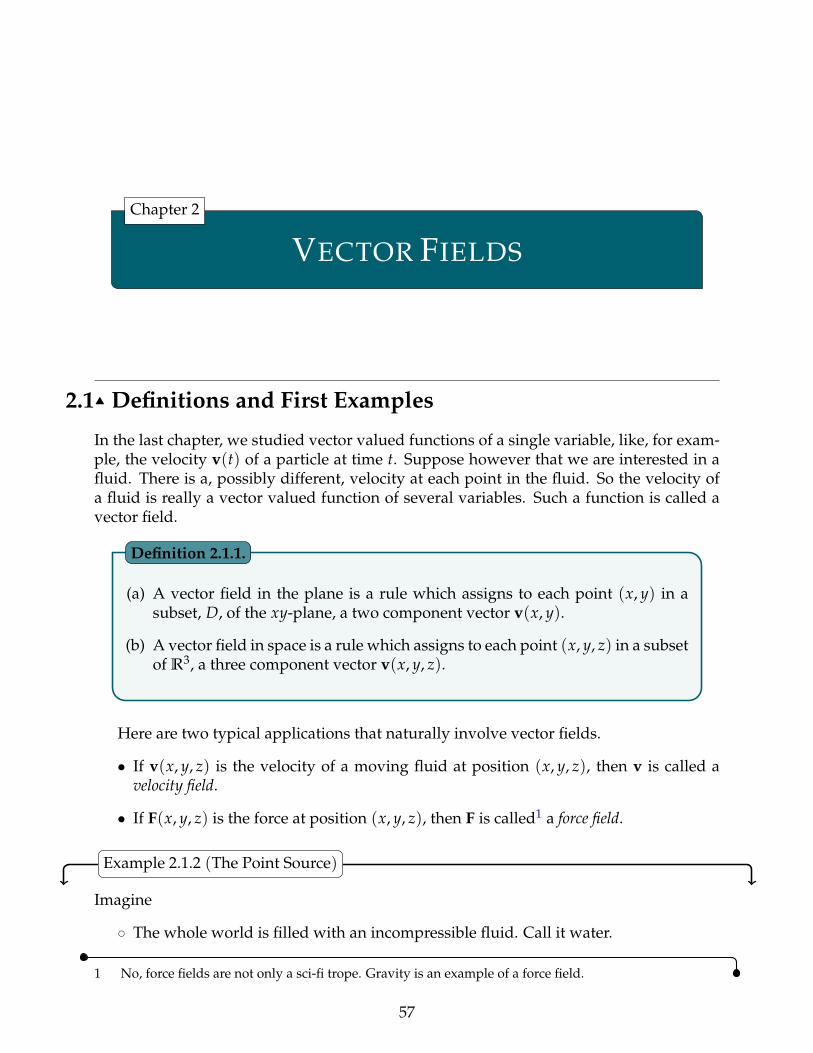
VECTOR FIELDS
Chapter 2
2.1IJ Definitions and First Examples
In the last chapter, we studied vector valued functions of a single variable, like, for exam-ple, the velocity v(t) of a particle at time t. Suppose however that we are interested in afluid. There is a, possibly different, velocity at each point in the fluid. So the velocity ofa fluid is really a vector valued function of several variables. Such a function is called avector field.
(a) A vector field in the plane is a rule which assigns to each point (x, y) in asubset, D, of the xy-plane, a two component vector v(x, y).
(b) A vector field in space is a rule which assigns to each point (x, y, z) in a subsetof R3, a three component vector v(x, y, z).
Definition 2.1.1.
Here are two typical applications that naturally involve vector fields.
• If v(x, y, z) is the velocity of a moving fluid at position (x, y, z), then v is called avelocity field.
• If F(x, y, z) is the force at position (x, y, z), then F is called1 a force field.
Example 2.1.2 (The Point Source)
Imagine
˝ The whole world is filled with an incompressible fluid. Call it water.
1 No, force fields are not only a sci-fi trope. Gravity is an example of a force field.
57

VECTOR FIELDS 2.1 DEFINITIONS AND FIRST EXAMPLES
˝ Somehow you find a way to produce still more water at the origin. Say you create4πm litres per second.
˝ This forces the water to flow outward. Let’s suppose that it flows symmetricallyoutward from the origin.
Let’s find the resulting vector field v(x, y, z). As the flow is to be symmetric, the velocityof the water at the point (x, y, z)
˝ has to be pointing radially outward from the origin. That is, the direction of thevelocity vector v(x, y, z) has to be the unit radial vector
r(x, y, z) =xııı + y + zka
x2 + y2 + z2
˝ The magnitude of the velocity, i.e. the speed |v(x, y, z)| of the water, has to dependonly on the distance from the origin. That is, the speed can only be some function of
r(x, y, z) =b
x2 + y2 + z2
Thus the velocity field is of the form
v(x, y, z) = v(r(x, y, z)
)r(x, y, z)
We just have to determine the function v(r). Fix any r ą 0 and concentrate on the spherex2 + y2 + z2 = r2. It is sketched in red in the figure below. During a very short time
vprq dt thick
interval dt seconds, 4πm dt litres of water is created at the origin (which is the red dot).As the water is incompressible, 4πm dt litres of water must exit through the sphere duringthe same time interval to make room for the newly created water.
But, at the surface of the sphere the water is flowing radially outward with speed v(r).So during the time interval in question the water near the surface of the sphere movesoutward a distance v(r) dt, and in particular the water that was in the thin spherical shellr ´ v(r) dt ď a
x2 + y2 + z2 ď r at the beginning of the time interval exits through thesphere
ax2 + y2 + z2 = r during the time interval. The shell is sketched in gray in the
figure above. The volume of water in the gray shell is essentially the surface area of theshell, which is 4πr2, times the thickness of the shell, which is v(r) dt. So, equating thevolume of water created inside the sphere with the volume of water that exited the sphere,
4πm dt = (4πr2)(v(r) dt
) ùñ v(r) =4πm4πr2 =
mr2
58

VECTOR FIELDS 2.1 DEFINITIONS AND FIRST EXAMPLES
Thus our vector field isv(x, y, z) =
mr(x, y, z)2 r(x, y, z)
If the world were two, rather than three dimensional2, and the source created 2πm litresper second, the same argument leads to
2πm dt = (2πr)(v(r) dt
) ùñ v(r) =2πm2πr
=mr
and to the vector field
v(x, y) =m
r(x, y)r(x, y) r(x, y) =
bx2 + y2 r(x, y) =
xııı + yax2 + y2
To get a mental image of what this field looks like, imagine sketching, for each point (x, y),the vector m
r(x,y) r(x, y) with its tail at (x, y). Note that the vector mr(x,y) r(x, y)
˝ points radially outward and˝ has length m
r(x,y) which
˝ depends only on r = |(x, y)| and˝ is very long when (x, y) is near the origin and˝ decreases in length like 1
r as r = |(x, y)| increases.
Here is a sketch of a bunch of such vectors.
x
y
vector field ~v “ m rr
Figure 2.1.1.
2 You might want to think about what happens in d dimensions for general d.
59

VECTOR FIELDS 2.1 DEFINITIONS AND FIRST EXAMPLES
Note that as |(x, y)| Ñ 0, the magnitude of the velocity |v(x, y)| Ñ 8. This is a conse-quence of our idealized assumption that we are producing water at a single point (theorigin).
Example 2.1.2
Example 2.1.3 (The Vortex)
In this example, we sketch the vector field
v(x, y) = Ω(´ yııı + x
)where Ω is just a strictly positive constant. We give an efficient procedure for getting arough sketch, which still provides a pretty realistic picture of the vector field, and whichalso generalises to other vector fields. First concentrate on the horizontal component ııı ¨v(x, y) of the vector field and determine in which part of the xy-plane it is zero, in whichpart it is positive and in which part it is negative.
ııı ¨ v(x, y) = ´Ωy
$’&’%
= 0 if y = 0ă 0 if y ą 0ą 0 if y ă 0
Next repeat with the vertical component.
¨ v(x, y) = Ωx
$’&’%
= 0 if x = 0ă 0 if x ă 0ą 0 if x ą 0
This naturally divides the xy-plane into nine parts according to whether each of the com-ponents is positive, 0 or negative —
˝ ııı ¨ v ą 0 and ¨ v ą 0 in (x, y) P R2
ˇy ă 0, x ą 0
(
˝ ııı ¨ v ą 0 and ¨ v = 0 in (x, y) P R2
ˇy ă 0, x = 0
(
˝ ııı ¨ v ą 0 and ¨ v ă 0 in (x, y) P R2
ˇy ă 0, x ă 0
(
˝ ııı ¨ v = 0 and ¨ v ą 0 in (x, y) P R2
ˇy = 0, x ą 0
(
˝ and so on
Now think of v(x, y) as being the velocity at (x, y) of a flowing fluid.
˝ Look at the first bullet point above. It says that in the first of the nine parts, namely (x, y) P R2
ˇy ă 0, x ą 0
(, which is the fourth quadrant, the horizontal com-
ponent ııı ¨ v ą 0 signifying that the fluid is flowing rightwards. Indicate this in thesketch by drawing a rightward pointing horizontal arrow at some generic point inthe middle of the fourth quadrant. (It’s the blue arrow in the figure below.) The ver-tical component ¨ v ą 0 signifying that the fluid is also moving upwards. Indicatethis in the sketch by drawing an upward pointing vertical arrow at the same genericpoint in the fourth quadrant. (It’s the red arrow in the figure below.)
60

VECTOR FIELDS 2.1 DEFINITIONS AND FIRST EXAMPLES
x
y
˝ Next, look at the second bullet point above. It says that on the second of the nineparts, namely
(x, y) P R2
ˇy ă 0, x = 0
(, which is the bottom half of the y-axis,
the horizontal component ııı ¨ v ą 0, signifying that the fluid is moving rightwards.Indicate this in the sketch by drawing a rightward pointing horizontal arrow at somegeneric point in the middle of the bottom half of the y-axis. (It’s the second bluearrow in the figure below.) The vertical component ¨ v = 0 signifying that the fluidhas no vertical motion at all. Indicate this in the sketch by not drawing any verticalarrow on the bottom half of the y-axis.
x
y
˝ and so on
By the time we have looked at all nine regions we will have built up the following sketch.
x
y
Figure 2.1.2.
61

VECTOR FIELDS 2.1 DEFINITIONS AND FIRST EXAMPLES
From this sketch we see that, for example, in the first quadrant,
• the fluid is moving upwards and to the left and• the fluid crosses the x-axis vertically (so that close to the x-axis, the arrows will be
almost vertical) and• the fluid crosses the y-axis horizontally (so that close to the y-axis, the arrows will
be almost horizontal) and• there is one point, namely (0, 0), where the vector field is exactly zero. It’s the black
dot in the centre of the figure above. Furthermore v(x, y) = Ω(´yııı + x) is smallerwhen (x, y) is closer to (0, 0) and v(x, y) is larger when (x, y) is farther from (0, 0),
Putting all of this accumulated wisdom together, we come up with this better sketch ofthe vector field.
x
y
vector field v “ Ωp´yııı ` xq
Figure 2.1.3.
This shows the field swirling around the origin in a counterclockwise direction. Hencethe name “vortex”.
Example 2.1.3
Example 2.1.4 (The Undamped Nonlinear Pendulum)
In this example, we illustrate another way in which vector fields arise. Model a pendulumby a mass m that is connected to a hinge by an idealized rod that is massless3 and of fixedlength `. Denote by θ the angle between the rod and vertical. The forces acting on the
3 While we are idealizing, let’s put everything in a vacuum.
62

VECTOR FIELDS 2.1 DEFINITIONS AND FIRST EXAMPLES
θℓ
mg
τ
mass are
˝ gravity and˝ the tension in the rod, whose magnitude, τ, automatically adjusts itself so that the
distance between the mass and the hinge is fixed at `.
In the optional4 Section 2.5, we show that the angle θ(t) obeys the second order nonlinear5
differential equationd2θ
dt2 +g`
sin θ = 0
It is often much more convenient to deal with first order, rather than second order, differ-ential equations. The second order pendulum equation above may be reformulated6 as asystem of first order ordinary differential equations, by the simple expedient of defining
x(t) = θ(t) y(t) = θ1(t)
So x(t) is the angle at time t and y(t) is the angular velocity at time t. Then,
x1(t) = θ1(t) = y(t)
y1(t) = θ2(t) = ´g`
sin x(t)
Usually, one does not write in the (t) dependence explicitly.
x1 = y
y1 = ´g`
sin x
The right hand sides form the vector field
v((x, y)
)=(
y , ´g`
sin x)
4 In the optional Section 2.5 we also include frictional forces. In this example, we do not, so set the β ofSection 2.5 to zero here.
5 It is common, when considering only small amplitude oscillations, to approximate sin θ by θ. Thisconverts our nonlinear differential equation into a linear differential equation.
6 This “hack” generalizes easily and is commonly used when generating, by computer, approximatesolutions to higher order ordinary differential equations.
63

VECTOR FIELDS 2.1 DEFINITIONS AND FIRST EXAMPLES
We can sketch this vector field, just as we sketched the vector field of Example 2.1.3. Not-ing that the horizontal component
ııı ¨ v(x, y) = y
$’&’%
= 0 if y = 0ą 0 if y ą 0ă 0 if y ă 0
and the vertical component.
¨ v(x, y) = ´g`
sin x
$’&’%
= 0 if x = 0, ˘π,˘2π, ¨ ¨ ¨ą 0 if ´π ă x ă 0, π ă x ă 2π, etc.ă 0 if 0 ă x ă π, 2π ă x ă 3π, etc.
we have
˝ rightward motion7 when y ą 0˝ leftward motion when y ă 0˝ downward motion when 0 ă x ă π, 2π ă x ă 3π, ¨ ¨ ¨ and˝ upward motion when ´π ă x ă 0, π ă x ă 2π, ¨ ¨ ¨ .
This gives us the collection of arrows in the figure
y “ 0
x “ ´π x “ 0 x “ π x “ 2π
Our full sketch will be less cluttered if we make all arrows the same length. This gives
7 Note that this is rightward motion of the point (x, y), not of the pendulum itself.
64

VECTOR FIELDS 2.2 OPTIONAL — FIELD LINES
x
y
direction field for x1 “ y, y1 “ ´2 sinx
which is a sketch of what is called the direction field of our vector field (see below).In the next section, we’ll learn how to use vector field sketches to sketch solution tra-
jectories.
Example 2.1.4
The direction field of a vector field v(x, y, z) is the vector field
V(x, y, z) =
$&%
v(x,y,z)|v(x,y,z)| if v(x, y, z) ‰ 0
0 if v(x, y, z) = 0
Definition 2.1.5.
2.2IJ Optional — Field Lines
Suppose that we drop a tiny stick into a river8 with the velocity field of the flowing waterbeing v(x, y). We are assuming, for simplicity, that the velocity field does not depend9 ontime t. The stick will move along with the water10. When the stick is at r, its velocity willbe the same as the velocity of the water at r, which is v(r). Thus if the stick is at r(t) attime t, we will have
drdt
= v(r(t)
)The stick will trace out a path, parametrized by r(t).
8 Think Poohsticks.9 This is not such an unreasonable assumption. The flow often changes on a larger time scale.10 This is also not an unreasonable approximation.
65

VECTOR FIELDS 2.2 OPTIONAL — FIELD LINES
A path that is parametrized by a function r(t) that obeys
drdt
= v(r(t)
)is called a
˝ field line or integral curve (for general vector fields) or a˝ stream line or flow line (when the vector field v is being thought of as a
velocity field) or a˝ line of force (when the vector field v is being thought of as a force field)
of the vector field v.
Definition 2.2.1.
Example 2.2.2 (Flow Line Sketch for the Vortex of Example 2.1.3)
Consider the vortex vector field, v(x, y) = Ω( ´ yııı + x
)of Example 2.1.3. Once we
sketched the vector field, as in Figure 2.1.3, or even made the “skeleton sketch” of Fig-ure 2.1.2, we can get rough idea of what the stream lines look like just by following thearrows. For example, suppose that we start a stream line (i.e. drop the stick into thestream) on the positive x-axis. Looking at Figure 2.1.2, which is repeated here,
x
y
the stick
˝ starts by moving in the +y direction, i.e. straight upward.˝ As it moves farther into the first quadrant it develops a larger and larger negative
x-component of velocity. So it also moves leftwards toward the y-axis.˝ Eventually it crosses the positive y-axis moving in the ´x direction, i.e. to the left.˝ As it moves farther into the second quadrant it develops a larger and larger negative
y-component of velocity. So it also moves downwards toward the x-axis.˝ Eventually it crosses the negative x-axis moving in the ´y direction, i.e. straight
downward.
66

VECTOR FIELDS 2.2 OPTIONAL — FIELD LINES
˝ As it moves farther into the third quadrant it develops a larger and larger positivex-component of velocity. So it also moves rightward towards the y-axis.
˝ Eventually it crosses the negative y-axis moving in the +x direction, i.e. to the right.˝ As it moves farther into the fourth quadrant it develops a larger and larger positive
y-component of velocity. So it also moves upwards toward the x-axis.
With this type of analysis we cannot tell if the streamline, which is the red line in the figureabove, will return to the x-axis
˝ exactly at its starting point, forming a closed curve, or˝ inside its starting point, spiralling inwards, or˝ outside its starting point, spiralling outwards.
Example 2.2.2
While the above procedure is a good way to get a qualitative feel for trajectories, wecan develop more precise, detailed descriptions of field lines by working analytically. Aswe saw above, thinking of r(t) as the position at time t of a stick dropped into waterwhose velocity at (x, y) is v(x, y), the velocity of the stick at time t will be the same as thevelocity of the water at r(t), which is v
(r(t)
). Thus r(t) will obey the system of first order
differential equations
drdt
(t) = v(r(t)
) Equation 2.2.3.
Notice that if we reparametrize r(t), say to R(u) = r(t(u)
), then R1(u) = r1
(t(u)
)t1(u)
is parallel to (though not necessarily equal to) r1(t(u)
)= v
(r((t(u)
))= v
(R(u)
). So if we
only care about the curve traced out by the stick, and not about when the stick is at eachpoint of the path, then it suffices to impose the weaker condition11 that, when the stickis at r(t), its velocity r1(t) is parallel to (though not necessarily equal to) v
(r(t)
). In three
dimensions, r1(t) is parallel to v(r(t)
)when the cross product is zero:
r1(t)ˆ v(r(t)
)= 0
Equation 2.2.4.
In two dimensions we can still use the cross product by the simple expedient of thinkingof r1(t) and v
(r(t)
)as three component vectors whose third components are zero.
A more convenient way to implement the weaker “just parallel” condition, involvesreparametrizing our streamline. Suppose that we are in two dimensions with r1(t) =(dx
dt (t) , dydt (t)
)and v(r) =
(v1(r) , v2(r)
)and fix some t0. If dx
dt (t0) is nonzero12, we canreparametrize the curve (at least near r(t0)) so as to use x, rather than t as the parameter.To do so, we
11 We’ll have a more careful discussion of this in the optional §2.2.1.12 If dx
dt (t0) = 0, but dydt (t0) ‰ 0, we should use y rather than x as the parameter. If dx
dt (t0) =dydt (t0) = 0,
then r(t) = r(t0) for all t and the streamline doesn’t move. It is just a single point.
67

VECTOR FIELDS 2.2 OPTIONAL — FIELD LINES
˝ solve x = x(t) for t as a function of x. Call the solution T(x). Then˝ the point on the curve which has x-coordinate x is R(x) =
(X(x) , Y(x)
)with
X(x) = x and Y(x) = y(T(x)
).
Then the condition that R1(x) =(1, Y1(x)
)is parallel to v
(R(x)
)says that R1(x) is a scalar
multiple of v(R(x)
)so that there is a nonzero number c(x) so that R1(x) = c(x)v
(R(x)
).
That is (1, Y1(x)
)=(c(x)v1
(x, Y(x)
), c(x)v2
(x, Y(x)
))or equivalently
Y1(x) =Y1(x)
1=
c(x) v2(x, Y(x)
)c(x) v1
(x, Y(x)
)) =v2(x, Y(x)
)v1(x, Y(x)
)This is exactly the statement that y = Y(x) is a solution of the differential equation
dydx
(x) =v2(x, y)
v1(x, y)
It is conventional to pretend13 that dydx is the ratio of dy and dx and rewrite the differential
equation14 as
dxv1(x, y)
=dy
v2(x, y)
Here is a summary of the discussion we have just completed. It extends to three di-mensions in an obvious way.
13 Of course dydx is not the ratio of dy and dx. However pretending that it is provides a simple way to
remember the technique that is used to solve the equation. You may have used this mnemonic de-vice before when you learned how to solve separable differential equations. Section 2.4 of the CLP-2text contains a treatment of separable differential equations, including a justification for the mnemonicdevice.
14 Here is another nonrigorous, but intuitive way to come up with this equation. Suppose that our stick isat (x, y) and has velocity
(dxdt (t) , dy
dt (t)). In a tiny time interval dt the stick moves by
(dxdt (t) , dy
dt (t))dt =
(dx, dy), which is parallel to(v1(x, y) , v2(x, y)
)if dx
v1(x,y) =dy
v2(x,y) .
68

VECTOR FIELDS 2.2 OPTIONAL — FIELD LINES
Use the symbol ‖ to stand for “is parallel to”.In two dimensions(dx
dt(t) ,
dydt
(t))‖(v1(r(t)) , v2(r(t)
)ðñ
(dxdt
(t) ,dydt
(t) , 0)ˆ (v1(r(t)) , v2(r(t)) , 0
)= 0
ðñ dxv1(x, y)
=dy
v2(x, y)
and in three dimensions(dxdt
(t) ,dydt
(t) ,dzdt
(t))‖(v1(r(t)) , v2(r(t)) , v3(r(t))
)ðñ
(dxdt
(t) ,dydt
(t) ,dzdt
(t))ˆ (v1(r(t)) , v2(r(t)) , v3(r(t))
)= 0
ðñ dxv1(x, y, z)
=dy
v2(x, y, z)=
dzv3(x, y, z)
Equation 2.2.5.
Let us apply this to two examples, in which the stream lines of the vortex field ofExample 2.1.3 are found by two different methods.
Example 2.2.6 (Stream lines for the vortex field using r1(t) ‖ v(r(t)))
In this example we will find the stream lines for the vortex field, v(x, y) = Ω(´ yııı + x
)of Example 2.1.3, by using the requirement that, on a stream line, the velocity vector r1(t)must be parallel to v
(r(t)
). By (2.2.5) one way to express this requirement mathematically
is
dx´Ωy
=dyΩx
This is a simple separable differential equation. We can solve it by cross multiplying andintegrating both sides. (Recall that Ω is a constant.)
Ωx dx = ´Ωy dy ðñ Ωż
x dx = ´Ωż
y dy
ðñ 12 Ωx2 = ´1
2 Ωy2 + C1
ðñ x2 + y2 = C
where C1 and C = 2Ω C1 are just arbitrary constants. So the stream lines of the vortex field
are exactly circles centred on the origin.
69

VECTOR FIELDS 2.2 OPTIONAL — FIELD LINES
x
y
We can come to exactly the same conclusion by using the cross product formulation of(2.2.4).(dx
dt(t) ,
dydt
(t) , 0)ˆ (v1(r(t)) , v2(r(t)) , 0
)= 0
ðñ(dx
dt(t) ııı +
dydt
(t) )ˆ (´Ωy(t) ııı + Ωx(t)
)= 0
ðñ(
Ωx(t)dxdt
(t) + Ωy(t)dydt
(t))
k = 0
ðñ Ωx(t)dxdt
(t) + Ωy(t)dydt
(t) = 0
ðñ ddt
(12 Ωx(t)2 + 1
2 Ωy(t)2)= 0 (Go ahead and evaluate the derivative.)
ðñ 12 Ω(x(t)2 + y(t)2) = C1
ðñ x(t)2 + y(t)2 = C
Example 2.2.6
Example 2.2.7 (Stream lines for the vortex field using r1(t) = v(r(t)))
This time we will find the stream lines for the vortex field, v(x, y) = Ω(´ yııı + x
)of Ex-
ample 2.1.3, by using (2.2.3), which is
dxdt
= ´Ωy
dydt
= Ωx
We can convert this system of first order linear ordinary differential equations into a singlesecond order linear constant coefficient differential equation15, by differentiating the first
15 In Example 2.1.4 we converted a second order ordinary differential equation into a system of first orderordinary differential equations. We are now just reversing the procedure we used there.
70

VECTOR FIELDS 2.2 OPTIONAL — FIELD LINES
equation, to get d2xdt2 = ´Ω dy
dt , and then substituting in the second equation to get
d2xdt2 + Ω2x = 0
This equation is a special case of the ordinary differential equation treated in Example I.3of the Appendix I, entitled “Review of Linear Ordinary Differential Equations”. In fact itis exactly (I.5h) with R = 0, L = C = 1
Ω . So the general solution is (I.7) with ρ = 0 andν = Ω, which is
x(t) = A cos(Ωt´ θ)
with A and θ being arbitrary constants16. Then
y(t) = ´ 1Ω
dxdt
= A sin(Ωt´ θ)
giving us the familiar circular stream lines.Example 2.2.7
2.2.1 §§ More about r1(t)ˆ v(r(t)
)= 0
Here is a lemma that gives a more precise version of “if we only care about the curvetraced out by the stick, and not about when the stick is at each point of the path, then itsuffices to impose the weaker condition r1(t)ˆ v
(r(t)
)= 0”.
Lat a ă b and let v(r) be a vector field. Assume that, for all a ă u ă b, R(u) isdefined, both R1(u) and v
(R(u)
)are continuous and nonzero and
R1(u)ˆ v(R(u)
)= 0
Then
R(u)ˇ
a ă u ă b(
is contained in a field line.
Lemma 2.2.8.
Proof. As R1(u)ˆ v(R(u)
)= 0 and both R1(u) and v
(R(u)
)are nonzero, there is an a(u)
such thatR1(u) = a(u) v
(R(u)
)This a(u) = R1(u)¨v(R(u))
v(R(u))¨v(R(u)) is necessarily nonzero and continuous. Since a(u) is nonzeroand continuous, it never changes sign. That is, either a(u) ą 0 for all u, or a(u) ă 0for all u. Let T(u) be an antiderivative of a(u). Then T(u) is strictly monotone (andcontinuous) and hence is invertible. That is, there is a continuous function U(t) that obeysU(T(u)
)= u for all a ă u ă b and T
(U(t)
)= t for all t in the range of U. Differentiating
16 Even if you don’t know how x(t) = A cos(Ωt´ θ) was arrived at, you should be able to easily verifythat it really does obey x2 + Ω2x = 0.
71

VECTOR FIELDS 2.2 OPTIONAL — FIELD LINES
T(U(t)
)= t gives T1
(U(t)
)U1(t) = 1 and hence U1(t) = 1
T1(U(t)) . Set r(t) = R(U(t)
).
Then
r1(t) = R1(U(t)
)U1(t) = a
(U(t)
)v(R(U(t)
)) 1T1(U(t)
) = a(U(t)
)v(r(t)
) 1a(U(t)
)= v
(r(t)
)So r(t) is a field line and R(u) = r(T(u)) is a reparametrization of r(t).
Here are a couple of examples that show that bad things can happen if we drop therequirement that v(R(u)) is nonzero.
Example 2.2.9
Let the vector field v(x, y) be identically zero. Then any field line(x(t) , y(t)
)must obey
x1(t) = 0 y1(t) = 0
which forces both x(t) and y(t) to be constants. So each field line is just a single point. Onthe other hand every nonconstant R(u) obeys R1(u)ˆ v
(R(u)
)= 0 but is not contained
in a field line. (As R(u) is not constant, it covers more than one point, while each field lineis just a single point.)
Example 2.2.9
Now here is a more interesting example.
Example 2.2.10
Consider the vector field v(x, y) = x ııı. This vector field takes the value 0 at each point onthe y-axis, is a positive multiple of ııı at every point of the right half-plane and is a negativemultiple of ııı at every point of the left half-plane. Let’s find the field lines. Any field linemust obey
dxdt
(t) = x(t)dydt
(t) = 0
So y(t) must be a constant. We can solve the linear ordinary differential equation dxdt (t) =
x(t) by moving the x(t) to the left hand side, and multiplying by the (integrating factor)e´t. This gives
e´t dxdt
(t)´ e´tx(t) = 0
By the product rule, this is the same as
ddt(e´tx(t)
)= 0
which forces e´tx(t) to be a constant. So our field lines are(Cet , D
), with C and D being
arbitrary constants. Note that
72

VECTOR FIELDS 2.3 CONSERVATIVE VECTOR FIELDS
• if C = 0, the field line is just the single point (0, D) on the y-axis. It is illustrated bythe black dot in the figure below.
• If C ą 0, then as t runs from ´8 to +8, the field line covers the horizontal half-line (x, D)
ˇx ą 0
(
in the right half-plane. It is illustrated by the red line in the figure below.
• If C ă 0, then as t runs from ´8 to +8, the field line covers the horizontal half-line (x, D)
ˇx ă 0
(
in the left half-plane. It is illustrated by the blue line in the figure below (with adifferent value of D than for the red line).
x
y
vector field v “ x ııı
On the other hand, fix any constant D and set R(u) = uııı + D. Then
R1(u)ˆ v(R(u)
)= ıııˆ (uııı) = 0
But as u runs from ´8 to +8, R(u) runs over the full line (x, D)
ˇ ´8 ă x ă 8 (. It
is not contained in any single field line and, in fact, completely covers three different fieldlines.
Example 2.2.10
2.3IJ Conservative Vector Fields
Not all vector fields are created equal. In particular, some vector fields are easier to workwith than others. One important class of vector fields that are relatively easy to workwith, at least sometimes, but that still arise in many applications are “conservative vectorfields”.
73

VECTOR FIELDS 2.3 CONSERVATIVE VECTOR FIELDS
(a) The vector field F is said to be conservative if there exists a function ϕ suchthat F =∇∇∇ϕ. Then ϕ is called a potential for F. Note that if ϕ is a potential forF and if C is a constant, then ϕ + C is also a potential for F.
(b) If F = ∇∇∇ϕ is a conservative field with potential ϕ and if C is a constant, thenthe set of points that obey ϕ(x, y, z) = C is called an equipotential surface.Similarly, in two dimensions, the set of points that obey ϕ(x, y) = C is calledan equipotential curve.
Definition 2.3.1.
In physics, when a vector field is of the form F = ´∇∇∇ϕ, then ϕ is called a potentialfor F. Note the minus17 sign in F =
Ò∇∇∇ϕ.
Warning 2.3.2.
Example 2.3.3 (Potential energy)
The “conservative” in “conservative vector field” has nothing to do with politics. It comesfrom “conservation of energy”. Here is how. Suppose that you have a particle of mass mmoving in a force field F that happens to be of the form F = ∇∇∇ϕ for some function ϕ. Ifthe position of the particle a time t is
(x(t), y(t), z(t)
), then, by Newton’s law of motion,
ma = F ùñ mdvdt
(t) = F(x(t), y(t), z(t)
)ùñ m
dvdt
(t) =∇∇∇ϕ(x(t), y(t), z(t)
)Now dot both sides with v(t).
ùñ m v(t) ¨ dvdt
(t) = v(t) ¨∇∇∇ϕ(x(t), y(t), z(t)
)= x1(t)
Bϕ
Bx(x(t), y(t), z(t)
)+ y1(t)
Bϕ
By(x(t), y(t), z(t)
)+ z1(t)
Bϕ
Bz(x(t), y(t), z(t)
)Next use d
dt v ¨ v = 2v ¨ dvdt on the left hand side and the chain rule on the right hand side.
ùñ ddt
(12
mv(t) ¨ v(t))=
ddt
(ϕ(x(t), y(t), z(t)
))ùñ d
dt
(12
mv(t) ¨ v(t)´ ϕ(x(t), y(t), z(t)
))= 0
ùñ 12
m|v(t)|2 ´ ϕ(x(t), y(t), z(t)
)= const
17 Physicists introduce this minus sign in order to eliminate the minus sign in the next footnote.
74

VECTOR FIELDS 2.3 CONSERVATIVE VECTOR FIELDS
So 12 m|v(t)|2 ´ ϕ
(x(t), y(t), z(t)
), which is called the energy18 of the particle at time t,
does not actually depend on time — it is conserved. Let’s call the initial energy E. That is,E = 1
2 m|v(0)|2 ´ ϕ(x(0), y(0), z(0)
). Then 1
2 m|v(t)|2 ´ ϕ(x(t), y(t), z(t)
)= E for all t and,
in particular
ϕ(x(t), y(t), z(t)
)=
12
m|v(t)|2 ´ E ě ´E
So even without having to find(x(t) , y(t) , z(t)
), we know that our particle can never
escape the region (x, y, z)
ˇϕ(x, y, z) ě ´E
(.
Example 2.3.3
Example 2.3.4 (Gravity)
The gravitational force that a body of mass M at the origin exerts on a body of mass m atr = (x, y, z) is
F(r) = ´GMmr3 r
where r = |r| = ax2 + y2 + z2 and G is the gravitational constant. This force is conserva-
tive, with potential ϕ(r) = GMmr . To verify that this is correct, observe that
BBx
ϕ(r) =BBx
GMmax2 + y2 + z2
= ´12
GMm(2x)[x2 + y2 + z2]3/2 = ´GMm
r3 x
BBy
ϕ(r) =BBy
GMmax2 + y2 + z2
= ´12
GMm(2y)[x2 + y2 + z2]3/2 = ´GMm
r3 y
BBz
ϕ(r) =BBz
GMmax2 + y2 + z2
= ´12
GMm(2z)[x2 + y2 + z2]3/2 = ´GMm
r3 z
Example 2.3.4
We have already found conservation of energy very helpful a couple of times in Section1.7 (Sliding on a Curve). So, at this point, there are probably several questions gnawingaway at you.
• Is every vector field conservative?
• If not, is there an easy way to tell whether or not a vector field is conservative?
• If we know that a given vector field is conservative, how do you find a potential forit?
Have no fear. We will consider those questions in some detail shortly. But first, a coupleof more examples.
Example 2.3.5
In this example we will show that the vector field F(x, y) = x ııı´ y is conservative andfind both its potential and its field lines.
18 12 m|v(t)|2 is the kinetic energy and ´ϕ is the potential energy. See Warning 2.3.2.
75

VECTOR FIELDS 2.3 CONSERVATIVE VECTOR FIELDS
(a) The potential: Our vector field F(x, y) = x ııı ´ y is conservative if we can find a ϕobeying
Bϕ
Bx(x, y) = x
Bϕ
By(x, y) = ´y
Recall that, when taking the partial derivative BBx the coordinate y is viewed as a con-
stant. So the first of these equations is satisfied if and only if there is a ψ(y), whichdoes not depend on x, so that
ϕ(x, y) =x2
2+ ψ(y)
For this to also satisfy the second equation, we need
´y =Bϕ
By(x, y) =
BBy
(x2
2+ ψ(y)
)= ψ1(y)
which is the case if and only if there is a constant C with
ψ(y) = ´y2
2+ C
So, for any choice of the constant C,
x2
2´ y2
2+ C
is a potential. In particular, taking C = 0, one possible potential is
ϕ(x, y) =x2
2´ y2
2
Some equipotential curves for this potential are sketched in (c) below. They are theblue curves.
(b) The field lines (Optional): Recalling (2.2.5), the field lines of the vector field F(x, y) =x ııı´ y are determined by
dxx
=dy´y
ðñ ´ydx = xdy
ðñ xdy + ydx = 0ðñ d(xy) = 0 by the product ruleðñ xy = C
76

VECTOR FIELDS 2.3 CONSERVATIVE VECTOR FIELDS
for some constant C. If you are not comfortable with the use of the product rule above,here is another way to write the same computation.
dydx
= ´yxðñ x
dydx
= ´y
ðñ xdydx
+ y = 0
ðñ ddx
(xy) = 0 by the product rule
ðñ xy = C
Some field lines are sketched in (c) below. They are the red curves. Note that theyappear to cross the equipotential curves, the blue curves, at right angles. We shall seein Lemma 2.3.6, below, that this is not a coincidence. Also note that, while the abovecomputation tells what the field lines are, it does not give us the direction of motionalong the field lines. We determine the direction of motion next.
(c) Direction of motion (Optional): The sign data
ııı ¨ F(x, y) = x
$’&’%
ą 0 if x ą 0= 0 if x = 0ă 0 if x ă 0
,/./-
¨ F(x, y) = ´y
$’&’%
ą 0 if y ă 0= 0 if y = 0ă 0 if y ą 0
,/./-
is visually displayed in the figure on the left below. The arrows in the figure on theleft gives us the direction of motion along the field lines (in red) in the figure on theright below. Some equipotential curves are also sketched (in blue) in the figure on theright below.
x
y
Example 2.3.5
We have just seen one example of a conservative vector field for which the field linesappear to cross the equipotential curves at right angles. Here is a result which says thatthat was no accident. The field lines of conservative fields always cross the equipotentialsurfaces at right angles.
77

VECTOR FIELDS 2.3 CONSERVATIVE VECTOR FIELDS
If F is a conservative vector field, then the field lines of F are perpendicular to theequipotential surfaces of F.
Lemma 2.3.6 (Optional).
Proof. Let F = ∇∇∇ϕ. Pick any point r0 and any nonzero vector T that is tangent to theequipotential surface at r0. That equipotential surface is ϕ
(x, y, z
)= ϕ(r0). Consider any
curve r(t) =(x(t), y(t), z(t)
)that
˝ lies in the equipotential surface of F through r0, so that ϕ(r(t)
)= ϕ(r0) for all t, and
also obeys˝ r(0) = r0 and˝ dr
dt (0) = T.
Differentiating ϕ(r(t)
)= ϕ(r0) with respect to t and applying the chain rule gives
ddt[ϕ(x(t), y(t), z(t)
)]= 0
Bϕ
Bx(x(t), y(t), z(t)
)dxdt
(t) +Bϕ
By(x(t), y(t), z(t)
)dydt
(t) +Bϕ
Bz(x(t), y(t), z(t)
)dzdt
(t) = 0
Notice that the left hand side is exactly the dot product of(BϕBx , Bϕ
By , BϕBz)
= ∇∇∇ϕ with(dxdt , dy
dt , dzdt)= dr
dt . So
∇∇∇ϕ(r(t)
) ¨ drdt
(t) = 0
F(r(t)
) ¨ drdt
(t) = 0
Then set t = 0 to getF(r0) ¨ T = 0
This says that the vector T (which is tangent to the equipotential surface at r0) is perpen-dicular to the vector field at r0 (which is a tangent vector to the field line of F throughr0).
Here is another example in which we try to find a potential for a vector field.
Example 2.3.7
Let’s try to find a potential for the vortex vector field v(x, y) = Ω(´ yııı + x
)of Example
2.1.3. The potential would have to obey
Bϕ
Bx(x, y) = ´Ωy
Bϕ
By(x, y) = Ωx
78

VECTOR FIELDS 2.3 CONSERVATIVE VECTOR FIELDS
We proceed just as we did in Example 2.3.5. The first of these equations is satisfied if andonly if there is a ψ(y), which does not depend on x, so that
ϕ(x, y) = ´Ωxy + ψ(y)
For this to also satisfy the second equation, we need
Ωx =Bϕ
By(x, y) =
BBy
(´Ωxy + ψ(y)
)= ´Ωx + ψ1(y) ðñ ψ1(y) = 2Ωx
If Ω ‰ 0, the right hand side of this equation depends on x while the left hand side inindependent of x, no matter what ψ is. So no ψ can work, and v(x, y) = Ω
(´ yııı + x)
isnot conservative.
Example 2.3.7
The previous example shows that not all vector fields are conservative. That answersthe first of the questions that we posed just before Example 2.3.5. The next theorem pro-vides a simple screening test for conservativeness, which partially answers the secondquestion. The easy way to remember the screening test uses the curl, which we now de-fine.
The curl of a vector field F(x, y, z) is denoted by∇∇∇ˆ F(x, y, z) and is defined by
∇∇∇ˆ F =(BF3
By´ BF2
Bz
)ııı +(BF1
Bz´ BF3
Bx
) +(BF2
Bx´ BF1
By
)k
= det
ııı kBBx
BBy
BBz
F1(x, y, z) F2(x, y, z) F3(x, y, z)
The determinant in the second row is really just a mnemonic device used to makeit easy to remember the expression after the equals sign in the first row. One mustbe careful about the signs in this definition — the determinant helps with that.
Definition 2.3.8.
79

VECTOR FIELDS 2.3 CONSERVATIVE VECTOR FIELDS
(a) Assume that F1(x, y) and F2(x, y) are continuously differentiable. If the vectorfield F1(x, y)ııı + F2(x, y) is conservative, then we must have
BF1
By=BF2
Bx
(b) Assume that F1(x, y, z), F2(x, y, z) and F3(x, y, z) are continuously differen-tiable. If the vector field F1(x, y, z)ııı+ F2(x, y, z)+ F3(x, y, z)k is conservative,then BF1
By=BF2
BxBF1
Bz=BF3
BxBF2
Bz=BF3
By
Equivalently,
∇∇∇ˆ F =(BF3
By´ BF2
Bz
)ııı +(BF1
Bz´ BF3
Bx
) +(BF2
Bx´ BF1
By
)k = 0
That is, F is curl free.
Theorem 2.3.9 (Screening test for conservative vector fields.).
Proof. (a) If the vector field F1(x, y)ııı + F2(x, y) is conservative, then there is a potentialϕ(x, y) such that
Bϕ
Bx(x, y) = F1(x, y)
Bϕ
By(x, y) = F2(x, y)
Applying BBy to the first equation and B
Bx to the second equation gives
B2ϕ
ByBx=BF1
ByB2ϕ
BxBy=BF2
Bx
Recall that, for any twice continuously differentiable function, B2 ϕByBx = B2 ϕ
BxBy . So the two lefthand sides are equal, and the two right hand sides must also be equal.(b) If the vector field F1(x, y, z)ııı + F2(x, y, z) + F3(x, y, z)k is conservative, then there is apotential ϕ(x, y, z) such that
Bϕ
Bx(x, y, z) = F1(x, y, z)
Bϕ
By(x, y, z) = F2(x, y, z)
Bϕ
Bz(x, y, z) = F3(x, y, z)
We proceed just as in (a).
80

VECTOR FIELDS 2.3 CONSERVATIVE VECTOR FIELDS
• Applying BBy to the first equation and B
Bx to the second equation gives$&%
B2 ϕByBx = BF1
ByB2 ϕBxBy = BF2
Bx
,.- ùñ BF1
By=BF2
Bx
• Applying BBz to the first equation and B
Bx to the third equation gives$&%
B2 ϕBzBx = BF1
BzB2 ϕBxBz = BF3
Bx
,.- ùñ BF1
Bz=BF3
Bx
• Applying BBz to the second equation and B
By to the third equation gives$&%
B2 ϕBzBy = BF2
BzB2 ϕByBz = BF3
By
,.- ùñ BF2
Bz=BF3
By
Combining the three bullet points gives∇∇∇ˆ F = 0.
As always, we have to be careful with the flow of logic19. The screening testin Theorem 2.3.9 is a one-way test. If, for example, BF1
By ‰ BF2Bx then the vector
field F cannot be conservative. But if BF1By = BF2
Bx Theorem 2.3.9 does not guaranteethat F is conservative. In fact there are fields that are not conservative but doobey BF1
By = BF2Bx . We’ll see one in Example 2.3.14, below. We shall later find some
additional regularity conditions which, when combined with BF1By = BF2
Bx , do implyconservativeness. See Theorem 2.4.8, below.
Warning 2.3.10.
Example 2.3.11 (Example 2.3.7 revisited)
In Example 2.3.7, we attempted to find a potential for the vector field
v(x, y) = Ω(´ yııı + x
)In the end we showed that, if Ω ‰ 0, no potential could exist, i.e. v(x, y) is not conserva-tive. Had we known the screening test of Theorem 2.3.9.a, we could have concluded thatv(x, y) is not conservative by simply observing that
Bv1
By=BBy(´Ωy)= ´Ω
Bv2
Bx=
BBx(Ωx) = +Ω
19 Use your favourite search engine to look up a list of common logical errors. One is “affirming theconsequent”. An example would be concluding that because Shakespeare is dead, Elvis, who is alsodead, must also be Shakespeare.
81

VECTOR FIELDS 2.3 CONSERVATIVE VECTOR FIELDS
are not equal, unless Ω = 0. But Ω = 0 makes a rather boring vector field.Example 2.3.11
Example 2.3.12
Determine whether or not the vector field
F(x, y, z) = yııı´ z + xk
is conservative. If it is conservative, find a potential.
Solution. Let’s start by applying the screening test Theorem 2.3.9.b. Since
∇∇∇ˆ F = det
ııı kBBx
BBy
BBz
y ´z x
= ııı´ ´ k
is not 0, the vector field F cannot be conservative.Example 2.3.12
Example 2.3.13
Determine whether or not the vector field
F(x, y, z) = (y2 + 2xz2 ´ 1)ııı + (2x + 1)y + (2x2z + z3)k
is conservative. If it is conservative, find a potential.
Solution. Again start by applying the screening test Theorem 2.3.9.b. This time
∇∇∇ˆ F = det
ııı kBBx
BBy
BBz
y2 + 2xz2 ´ 1 (2x + 1)y 2x2z + z3
= 0ııı´ (4xz´ 4xz) + (2y´ 2y)k
= 0
So F passes the screening test. Let’s look for a function ϕ(x, y, z) obeying
Bϕ
Bx(x, y, z) = y2 + 2xz2 ´ 1
Bϕ
By(x, y, z) = (2x + 1)y (˚)
Bϕ
Bz(x, y, z) = 2x2z + z3
The partial derivative BBx treats y and z as constants. So ϕ(x, y, z) obeys the first equation
if and only if there is a function ψ(y, z) with
ϕ(x, y, z) = xy2 + x2z2 ´ x + ψ(y, z)
82

VECTOR FIELDS 2.3 CONSERVATIVE VECTOR FIELDS
This ϕ(x, y, z) will also obey the second equation if and only if
BBy(
xy2 + x2z2 ´ x + ψ(y, z))= (2x + 1)y ðñ 2xy +
Bψ
By(y, z) = (2x + 1)y
ðñ Bψ
By(y, z) = y
ðñ ψ(y, z) =y2
2+ ζ(z)
for some function ζ(z) which depends only on z. At this stage we know that
ϕ(x, y, z) = xy2 + x2z2 ´ x + ψ(y, z) = xy2 + x2z2 ´ x +y2
2+ ζ(z)
obeys the first two equations of (˚), for any function ζ(z). Finally to have the third equationof (˚) also satisfied, we also need to chose ζ(z) to obey
BBz
(xy2 + x2z2 ´ x +
y2
2+ ζ(z)
)= 2x2z + z3 ðñ 2x2z + ζ1(z) = 2x2z + z3
ðñ ζ1(z) = z3
ðñ ζ(z) =z4
4+ C
for any constant C. So one possible potential, namely that with C = 0, is
ϕ(x, y, z) = xy2 + x2z2 ´ x +y2
2+
z4
4Note, as a check20, that
∇∇∇ϕ(x, y, z) =(y2 + 2xz2 ´ 1
)ııı +(2xy + y) +
(2x2z + z3)k
as desired.Example 2.3.13
Example 2.3.14(
Optional: First look at ´ yx2+y2 ııı + x
x2+y2 )
Now is a good time to reread Warning 2.3.10. In this example we will show that the vectorfield
F(x, y) = ´ yx2 + y2 ııı +
xx2 + y2 defined for all (x, y) in R2 except (x, y) = (0, 0)
passes the screening test of Theorem 2.3.9.a. We will also begin to see why it is not conser-vative on the domain R2zt(0, 0)u. To verify the screening test, we compute
BBy
(´ y
x2 + y2
)= ´(x2 + y2)´ y(2y)
(x2 + y2)2 =y2 ´ x2
(x2 + y2)2
BBx
( xx2 + y2
)=
(x2 + y2)´ x(2x)
(x2 + y2)2 =y2 ´ x2
(x2 + y2)2
20 It is always worth doing this check.
83

VECTOR FIELDS 2.3 CONSERVATIVE VECTOR FIELDS
and observe that the two right hand sides are identical. So the screening test is passed.In order for F to be conservative on the domain R2zt(0, 0u, there must exist a function
ϕ(x, y), that, together with both partial derivatives BϕBx (x, y) and Bϕ
By (x, y), is defined for all(x, y) in R2 except (x, y) = (0, 0), and obeys
Bϕ
Bx(x, y) = ´ y
x2 + y2 =´ y
x2
1 +( y
x)2 =
BBx
(arctan
yx
)Bϕ
By(x, y) =
xx2 + y2 =
1x
1 +( y
x)2 =
BBy
(arctan
yx
)by the chain rule, because
BBx
(yx
)= ´ y
x2BBy
(yx
)=
1x
It looks like we have found a potential, namely arctan yx . But there is a problem. Recall
that, by definition, arctan yx is an angle θ(x, y) that obeys tan θ(x, y) = arctan y
x ; but forany (x, y) P R2zt(0, 0u there are infinitely many angles having the tangent y
x . To defineϕ(x, y) we have to select exactly one such angle. It is impossible to do so in such a waythat ϕ(x, y) is continuous on all of R2zt(0, 0u.
To see why, fix any r ą 0, and imagine that you are walking on the circle x2 + y2 = r2
in the xy-plane. At time θ, you are at x = r cos θ, y = r sin θ and then yx = tan θ and you
are allowed to define ϕ(x, y) = θ + kπ, for any integer k.Suppose that at time θ = 0 you choose k = 0. That is, you choose ϕ(r, 0) = 0. Now
start walking, choosing an allowed ϕ(x, y), i.e. choosing a k, for each point (x, y) thatyou cross. Because ϕ(x, y) has to vary continuously21 with (x, y), you have to continuechoosing k = 0. But you run off a cliff as θ approaches 2π, because then
˝ you are approaching (r, 0) from below, as in the figure below, and
˝ because you are choosing k = 0, ϕ(x, y) is just a little less than 2π, but
˝ you have already chosen ϕ(r, 0) = 0, not 2π. So ϕ(x, y) has a jump discontinuity22
along the positive x-axis.
x
y
ϕ “ 0
ϕ “ π8ϕ “ 2π8
ϕ “ 3π8ϕ “ 5π8ϕ “ 6π8
ϕ “ 7π8ϕ “ π
ϕ “ 9π8ϕ “ 10π8
ϕ “ 11π8 ϕ “ 13π8ϕ “ 14π8
ϕ “ 15π8
21 If ϕ(x, y) is not continuous, its gradient does not exist, and ϕ cannot be a potential.22 Those who have taken some complex analysis may recognize this as the branch cut in ln z.
84

VECTOR FIELDS 2.4 LINE INTEGRALS
If you are having trouble following this argument, don’t worry about it. We will returnwith a less hand-wavy argument later.
Example 2.3.14
2.4IJ Line Integrals
We have already seen, in §1.6, one type of integral along curves. We are now going to seea second, that turns out to have significant connections to conservative vector fields. Itarose from the concept of “work” in classical mechanics.
Suppose that we wish to find the work done by a force F(r) moving a particle alonga path r(t). During the “infinitesimal time interval23” from t to t + dt the particle movesfrom r(t) to r(t) + dr with dr = dr
dt (t)dt. By definition, the work done during that in-finitesimal time interval is
F(r(t)
) ¨ dr = F(r(t)
) ¨ drdt
(t)dt
The total work done during the time interval from t0 to t1 is then
Work =
ż t1
t0
F(r(t)
) ¨ drdt
(t)dt
There are some useful shorthand notations for this work.
Denote by C the parametrized path r(t) with t0 ď t ď t1. Then
ż
CF ¨ dr =
ż
C
(F1dx + F2dy + F3dz
)=
ż t1
t0
F(r(t)
) ¨ drdt
(t)dt
If C is a closed path, the notationűC F ¨ dr is also used.
Notation 2.4.1.
In the event that F is conservative, and we know the potential ϕ, the following theoremprovides a really easy way to compute “work integrals”. The theorem is a generalizationof the fundamental theorem of calculus, and indeed some people call it the fundamentaltheorem of line integrals.
23 Yes, yes. We should first consider short time intervals ∆t ą 0 and then take the limit ∆t Ñ 0 at theend. But you have undoubtedly used this type of argument so many times before that you would bethoroughly bored by it.
85

VECTOR FIELDS 2.4 LINE INTEGRALS
Let F = ∇ϕ be a conservative vector field. Then if C is any curve that starts at P0and ends at P1, we have24
ż
CF ¨ dr = ϕ(P1)´ ϕ(P0)
Theorem 2.4.2.
Proof. Let r(t) =(x(t), y(t), z(t)
), t0 ď t ď t1, be any parametrization of C with r(t0) = P0
and r(t1) = P1. Then, by definition,
ż
CF ¨ dr =
ż t1
t0
F(r(t)
) ¨ drdt
(t)dt =ż t1
t0
∇∇∇ϕ(r(t)
) ¨ drdt
(t)dt
=
ż t1
t0
[Bϕ
Bx(x(t), y(t), z(t)
)dxdt
(t) +Bϕ
By(x(t), y(t), z(t)
)dydt
(t)
+Bϕ
Bz(x(t), y(t), z(t)
)dzdt
(t)]dt
=
ż t1
t0
ddt
[ϕ(x(t), y(t), z(t)
)]dt by the chain rule in reverse
= ϕ(r(t1)
)´ ϕ(r(t0)
)= ϕ(P1)´ ϕ(P0)
by the fundamental theorem of calculus.
Observe that, in Theorem 2.4.2, the value, ϕ(P1) ´ ϕ(P0), of the integralşC F ¨ dr de-
pended only on the endpoints P0 and P1 of the curve, not on the path that the curvefollowed to get to P0 from P1. We shall see, in Theorem 2.4.7, below, that this happensonly for conservative vector fields. Here are several examples of line integrals of vectorfields that are not conservative.
Example 2.4.3
Set P0 = (0, 0), P1 = (1, 1) and25
F(x, y) = xy ııı + (y2 + 1)
We shall consider three curves, all starting at P0 and ending at P1.
(a) Let C1 be the straight line from P0 to P1.
(b) Let C2 be the path, made from two straight lines, which follows the x-axis from P0 to(1, 0) and then follows the line x = 1 from (1, 0) to P1.
(c) Let C3 be the part of the parabola x = y2 from P0 to P1.
24 So ϕ acts a bit like the antiderivative of first year calculus.25 The reader should check that this vector field is not conservative.
86

VECTOR FIELDS 2.4 LINE INTEGRALS
x
y
P0
P1
C1
C2
C2
C3
We shall calculate the workşCi
F ¨ dr for each of the curves.
(a) We parametrize C1 by r(t) = t ııı + t with t running from 0 to 1. Then x(t) = t andy(t) = t so that
F(r(t)
)= t2 ııı + (t2 + 1) and
drdt
(t) = ııı +
so thatż
C1
F ¨ dr =ż 1
0F(r(t)
) ¨ drdt
(t)dt =ż 1
0
[t2 ııı + (t2 + 1)
] ¨ [ııı + ]dt
=
ż 1
0
[2t2 + 1
]dt
=53
(b) We split C2 into two parts, C2,x running from P0 to (1, 0) along the x-axis and then C2,yrunning from (1, 0) to P1 along the line x = 1. We parametrize C2,x by r(x) = x ııı withx running from 0 to 1 and C2,y by r(y) = ııı + y with y running from 0 to 1. Then26
ż
C2
F ¨ dr =ż
C2,x
F ¨ dr +ż
C2,y
F ¨ dr
=
ż 1
0
[(x)(0) ııı + (02 + 1)
] ¨ıııhkkkikkkj
ddx(x ııı)
dx +
ż 1
0
[(1)(y) ııı + (y2 + 1)
] ¨hkkkkkikkkkkj
ddy(ııı + y
)dy
=
ż 1
00 dx +
ż 1
0
(y2 + 1
)dy
=43
(c) We parametrize C3 by r(t) = t2 ııı + t with t running from 0 to 1. Then x(t) = t2 andy(t) = t so that
F(r(t)
)= t3 ııı + (t2 + 1) and
drdt
(t) = 2t ııı +
26 You might like to think about why we can split up the integral like this.
87

VECTOR FIELDS 2.4 LINE INTEGRALS
so thatż
C3
F ¨ dr =ż 1
0
[t3 ııı + (t2 + 1)
] ¨ [2t ııı + ]dt =ż 1
0
[2t4 + t2 + 1
]dt
=25+
13+ 1 =
2615
Note that, despite the fact that C1, C2 and C3 all start at P0 and all end at P1, the threeintegrals
şC1
F ¨ dr,şC2
F ¨ dr andşC3
F ¨ dr all have different values.
Example 2.4.3
Example 2.4.4
Set27
F(x, y) = 2y ııı + 3x
This time we consider two curves.
(a) Let C1 be circle x2 + y2 = 1, traversed once counterclockwise, starting at (1, 0).
(b) Let C2 be (trivial) curve which just consists of the single point (1, 0).
We shall calculate the workşCi
F ¨ dr for each curve.
(a) We parametrize C1 by r(t) = cos t ııı + sin t with t running from 0 to 2π, just as we didin Example 1.0.1. Then
¿
C1
F ¨ dr =ż 2π
0
[2 sin t ııı + 3 cos t
] ¨ [´ sin t ııı + cos t ]dt =ż 2π
0
[´ 2 sin2 t + 3 cos2 t]
dt
You could evaluate these integrals using double angle trig identities like you didin first year calculus. But there is a sneaky, much easier, way. Because sin2 t andcos2 t are translates of each other, and both are periodic of period π, the two integralsş2π
0 sin2 t dt andş2π
0 cos2 t dt represent the same area and so are equal. See the figurebelow.
y
xππ2 2π3π2
1y “ sin2 x
y
xππ2 2π3π2
1y “ cos2 x
27 Again, the reader should verify that this vector field is not conservative.
88

VECTOR FIELDS 2.4 LINE INTEGRALS
Thusż 2π
0sin2 t dt =
ż 2π
0cos2 t dt =
ż 2π
0
12[
sin2 t + cos2 t]
dt =12
ż 2π
0dt = π
and¿
C1
F ¨ dr = ´2ż 2π
0sin2 t dt + 3
ż 2π
0cos2 t dt = π
(b) We parametrize C2 by r(t) = ııı for all t. Then drdt (t) = 0 and
şC2
F ¨ dr = 0.
Again, despite the fact that C1 and C2 both start at (1, 0) and end at (1, 0), the two integralsşC1
F ¨ dr andşC2
F ¨ dr are different.
Example 2.4.4
Example 2.4.5 (Example 2.3.14, again.)
In Example 2.3.14, we saw that the vector field
F(x, y) = ´ yx2 + y2 ııı +
xx2 + y2 defined for all (x, y) in R2 except (x, y) = (0, 0)
passed the screening test of Theorem 2.3.9.a, and yet was not conservative. In this exam-ple, we will see that this F violates the conclusion of Theorem 2.4.2, thereby providing asecond proof that F(x, y) is not conservative on R2 with (0, 0) removed. For the curve C,of Theorem 2.4.2, we use the circle parametrized by x = a cos θ, y = a sin θ, 0 ď θ ď 2π.Then dx = ´a sin θ dθ and dy = a cos θ dθ so that
12π
ż
C
x dy´ y dxx2 + y2 =
12π
ż 2π
0
a2 cos2 θ dθ + a2 sin2 θ dθ
a2 cos2 θ + a2 sin2 θ=
12π
ż 2π
0dθ = 1
The curve C has initial point
P0 = (a cos θ, a sin θ)ˇθ=0 = (a, 0)
and final point
P1 = (a cos θ, a sin θ)ˇθ=2π
= (a, 0) = P0
So, if F were conservative with potential ϕ, Theorem 2.4.2 would give that
12π
ż
C
x dy´ y dxx2 + y2 = ϕ(P1)´ ϕ(P0) = 0
Consequently, F can’t be conservative.Example 2.4.5
89

VECTOR FIELDS 2.4 LINE INTEGRALS
2.4.1 §§ Path Independence
This brings us to the following question. Let F be any fixed vector field. When is it truethat, given any two fixed points P0 and P1, the integrals
ż
CF ¨ dr =
ż
C1
F ¨ dr
for all curves C, C 1 that start at P0 and end at P1? When can we ignore the path taken? Ifthis is the case we say that “
şC F ¨ dr is independent of the path chosen” and we write
ż P1
P0
F ¨ dr =ż
CF ¨ dr
for any path C from P0 to P1. The point of this section is that there is an intimate relationbetween path independence and conservativeness of vector fields, that we will get to inTheorem 2.4.7.
For simplicity, we will consider only vector fields that are defined and continuous onall of R2 (i.e. the xy-plane) or R3 (i.e. the usual three dimensional world). Some discussionabout what happens for vector fields that are defined only on part of R2 or R3 is given inthe optional §4.5.
First we show that if there is one pair of (not necessarily distinct) points P0, P1 suchthat ż
C1
F ¨ dr =ż
C2
F ¨ dr
for all curves C1, C2 that start at P0 and end at P1, then it is also true that, for any other pairof points P10, P11 ż
C11
F ¨ dr =ż
C12
F ¨ dr
for all curves C 11, C 12 that start at P10 and end at P11. This might seem unlikely at first, but theidea of the proof is really intuitive.
Let F be a vector field that is defined and continuous on all of R2 (or R3). Let P0,P1, P10, P11 be any four points in R2 (or R3). Assume that
ż
C1
F ¨ dr =ż
C2
F ¨ dr
for all curves C1, C2 that start at P0 and end at P1. Thenż
C11
F ¨ dr =ż
C12
F ¨ dr
for all curves C 11, C 12 that start at P10 and end at P11.
Theorem 2.4.6.
90

VECTOR FIELDS 2.4 LINE INTEGRALS
Proof. Let C 11 and C 12 be any two curves that start at P10 and end at P11. We start by choosing
P 10
P 11
P0
P1
CℓCr
C11
C12
any two (auxiliary) curves
˝ C` that starts at P0 and ends at P10 and˝ Cr that starts at P11 and ends at P1.
and then we define the curves
˝ C1 to be C`, followed by C11, followed by Cr and˝ C2 to be C`, followed by C12, followed by Cr.
Then both C1 and C2 start at P0 and end at P1, so that, by hypothesis,ż
C1
F ¨ dr =ż
C2
F ¨ dr
and, from the construction of C1 and C2,ż
C`F ¨ dr +
ż
C11
F ¨ dr +ż
Cr
F ¨ dr =ż
C`F ¨ dr +
ż
C12
F ¨ dr +ż
Cr
F ¨ dr
ùñż
C11
F ¨ dr =ż
C12
F ¨ dr
as desired.
We are now ready for our main theorem on conservative fields.
Let F be a vector field that is defined and continuous on all of R2 (or R3). Thenthe following three statements are equivalent.
(a) F is conservative. That is, there exists a function ϕ such that F =∇∇∇ϕ.
(b) The integralűC F ¨ dr = 0 for any closed curve C.
(c) The integralş
F ¨ dr is path independent. That is, for any points P0, P1 wehave
şC1
F ¨ dr =şC2
F ¨ dr for all curves C1, C2 that start at P0 and end at P1.
That is, if any one of the three statements are true, then all three are true.
Theorem 2.4.7.
91

VECTOR FIELDS 2.4 LINE INTEGRALS
Proof. It suffices for us to prove28 that
˝ the truth of (a) implies the truth of (b) and˝ the truth of (b) implies the truth of (c) and˝ the truth of (c) implies the truth of (a).
That’s exactly what we will do.(a) ùñ (b): Let C be a closed curve that starts at P0 and then ends back at P0. Then, byTheorem 2.4.2 with P1 = P0,
¿
C
F ¨ dr = ϕ(P0)´ ϕ(P0) = 0
(b) ùñ (c): Pick any point P0 and set P1 = P0. Then we are assuming thatűC F ¨ dr = 0 for
all curves that start at P0 and end at P1. In particularşC F ¨ dr takes the same value for all
curves that start at P0 and end at P1. So Theorem 2.4.6 immediately yields property (c).
(c) ùñ (a): We are to show that F is conservative. We’ll start by guessing ϕ and then we’llverify that, for our chosen ϕ, we really do have F = ∇∇∇ϕ. Our guess for ϕ is motivatedby Theorem 2.4.2. If our F really is conservative, its potential is going to have to obeyşC F ¨ dr = ϕ(P1) ´ ϕ(P0) for any curve C that starts at P0 and ends at P1. Let’s choose
P0 = 0. Remembering, from Definition 2.3.1.a, that adding a constant to a potential alwaysyields another potential, we can always choose ϕ(0) = 0. Then ϕ(P1) =
şC F ¨ dr for any
curve C that starts at 0 and ends at P1. So define, for each point x, ϕ(x) =şC F ¨ dr for any
curve C that starts at 0 and ends at x. Note that, since we we are assuming that (c) is true,the integral
şC F ¨ dr takes the same value for all curves C that start at 0 and end at x.
We now verify that, for this chosen ϕ, we really do have F = ∇∇∇ϕ. Fix any point x andany curve Cx that starts at the origin and ends at x. For any vector u, let Du be the curvewith parametrization
ru(t) = x + tu 0 ď t ď 1
This curve is a line segment that starts at x at t = 0 and ends at x + u at t = 1. Observethat r 1u(t) = u. Recall that, by assumption, ϕ(x + su) =
şC F ¨dr for any curve C that starts
at 0 and ends at x + su. Soϕ(x + su) =
ż
Cx+Dsu
F ¨ dr
where Cx + Dsu is the curve which first follows Cx from the origin to x and then followsDsu from x to x + su. We have
ż
Cx+Dsu
F ¨ dr =ż
Cx
F ¨ dr +ż
Dsu
F ¨ dr
=
ż
Cx
F ¨ dr +ż 1
0F(x + tsu) ¨ (su) dt
In the second integral, make the change of variables τ = ts, dτ = sdt. This gives
ϕ(x + su) =ż
Cx
F ¨ dr +ż s
0F(x + τu) ¨ u dτ
28 This is a pretty efficient, and standard, way to structure the proof of the equivalence of three statements.
92

VECTOR FIELDS 2.4 LINE INTEGRALS
By the fundamental theorem of calculus, applied to the second integral,
dds
ϕ(x + su)ˇˇs=0
= F(x + su) ¨ uˇˇs=0
= F(x) ¨ u
Applying this with u = ııı, , k gives us(Bϕ
Bx(x) ,
Bϕ
By(x) ,
Bϕ
Bz(x))=(F(x) ¨ ııı , F(x) ¨ , F(x) ¨ k)
which is∇ϕ(x) = F(x)
as desired.
Using this result, we can completely characterize conservative fields on R2 and R3.
Let F be a vector field that is defined and has continuous first order partial deriva-tives on all of R2 (or R3). Then F is conservative if and only if it passes thescreening test∇∇∇ˆ F = 0, i.e. is curl free.
Theorem 2.4.8.
Note that in Theorem 2.4.8 we are assuming that F passes the screening test onall of R2 or R3. We have already seen, in Example 2.3.14, that if the screening testfails at even a single point, for example because the vector field is not defined atthat point, then F need not be conservative. We’ll explore what happens in suchcases in the (optional) §4.5. We’ll see that something can be salvaged.
Warning 2.4.9.
Proof of Theorem 2.4.8. We’ll give the proof for the R2 case. The proof for the R3 case isvery similar. We have already seen, in Theorem 2.3.9, that if F is conservative, then itpasses the screening test and there is nothing more to do.
So we now have to assume that F obeys BF1By (x, y) = BF2
Bx (x, y) on all of R2 and provethat it is conservative. We’ll do so using the strategy of Example 2.3.13 to find a functionϕ(x, y), that obeys
Bϕ
Bx(x, y) = F1(x, y)
Bϕ
By(x, y) = F2(x, y)
The partial derivative BBx treats y as a constant. So ϕ(x, y) obeys the first equation if and
only if there is a function ψ(y) with
ϕ(x, y) =ż x
0F1(X, y)dX + ψ(y)
93

VECTOR FIELDS 2.5 OPTIONAL — THE PENDULUM
This ϕ(x, y) will also obey the second equation if and only if
F2(x, y) =Bϕ
By(x, y)
=BBy
( ż x
0F1(X, y)dX + ψ(y)
)=
ż x
0
BF1
By(X, y)dX + ψ1(y)
So we have to find a ψ(y) that obeys
ψ1(y) = F2(x, y)´ż x
0
BF1
By(X, y)dX
This looks bad — no matter what ψ(y) is, the left hand side is independent of x, whileit looks like the right hand side depends on x. Fortunately our screening test hypothesisnow rides in to the rescue29. (We haven’t used it yet, and it has to come in somewhere.)
F2(x, y)´ż x
0
BF1
By(X, y)dX = F2(x, y)´
ż x
0
BF2
Bx(X, y)dX
= F2(x, y)´ F2(X, y)ˇˇX=x
X=0
= F2(0, y)
In going from the first line to the second line we used the fundamental theorem of calculus.So choosing
ψ(y) =ż y
0F2(0, Y)dY + C
for any constant C, does the trick.
2.5IJ Optional — The Pendulum
Model a pendulum by a mass m that is connected to a hinge by an idealized rod that ismassless and of fixed length `. Denote by θ the angle between the rod and vertical. The
θℓ
mg
τ βℓdθdt θ
ℓℓ cos θ
ℓ sin θ
ııı
29 or bails us out, or saves our bacon, or . . .
94

VECTOR FIELDS 2.5 OPTIONAL — THE PENDULUM
forces acting on the mass are
˝ gravity, which has magnitude mg and direction (0,´1),˝ tension in the rod, whose magnitude, τ, automatically adjusts itself so that the dis-
tance between the mass and the hinge is fixed at ` and whose direction, (´ sin θ, cos θ),is always parallel to the rod and
˝ possibly some frictional forces, like friction in the hinge and air resistance. We shallassume that the total frictional force has magnitude proportional to the speed30 ofthe mass and has direction opposite to the direction of motion of the mass.
If we use a coordinate system centered on the hinge, the (x, y) coordinates of the mass attime t are `
(sin θ(t),´ cos θ(t)
). Hence its velocity vector is
v(t) =ddt[`(
sin θ(t),´ cos θ(t))]
= `(
cos θ(t), sin θ(t))dθ
dt(t)
and the total frictional force is ´β`(cos θ, sin θ)dθdt , for some constant β. The acceleration
vector of the mass is
a(t) =ddt
v(t) = `(cos θ, sin θ)d2θ
dt2 + `(´ sin θ, cos θ)(dθ
dt
)2
so that Newton’s law of motion, F = ma, now tells us
ma(t) = m`(cos θ, sin θ)d2θ
dt2 + m`(´ sin θ, cos θ)(dθ
dt
)2
= F = mg(0,´1) + τ(´ sin θ, cos θ)´ β`(cos θ, sin θ)dθ
dt
To eliminate the (unknown) coefficient τ we dot this equation with (cos θ, sin θ), whichextracts the component parallel to the direction of motion of the mass. Dotting with(cos θ, sin θ) gives m`d2θ
dt2 = ´mg sin θ ´ β`dθdt or
d2θ
dt2 +β
mdθ
dt+
g`
sin θ = 0
which is the equation of motion of the (nonlinear) pendulum. In general, it can be hardto analyse nonlinear differential equations. But if the amplitude of oscillation is smallenough that we may approximate sin θ by θ we get the equation of motion of the linearpendulum31 which is
d2θ
dt2 +β
mdθ
dt+
g`
θ = 0
30 The dependence of air resistance (drag) on the speed v is relatively complex. At low speed drag tendsto be approximately proportional to v, while at high speed it tends to be approximately proportional tov2.
31 When β = 0, this equation reduces to the equation d2θdt2 + g
` θ = 0, which occurs in many differentapplications, and whose solutions exhibit simple harmonic motion.
95

VECTOR FIELDS 2.5 OPTIONAL — THE PENDULUM
These equations may be reformulated as systems of first order ordinary differential equa-tion, that is as equations for the flow lines of a vector field, by the simple expedient ofdefining (as we did in Example 2.1.4)
x(t) = θ(t) y(t) = θ1(t)
Then, for the full, nonlinear, equation d2θdt2 + β
mdθdt +
g` sin θ = 0
x1(t) = θ1(t) = y(t)
y1(t) = θ2(t) = ´g`
sin x(t)´ β
my(t)
The solutions of this first order system of ordinary differential equations are flow lines forthe vector field
V((x, y)
)=(
y , ´g`
sin x´ β
my)
When β = 0, this is exactly the vector field of Example 2.1.4.
96

SURFACE INTEGRALS
Chapter 3
3.1IJ Parametrized Surfaces
For many applications we will need to use integrals over surfaces. One obvious one is justcomputing surface areas. Another is computing the rate at which fluid traverses a surface.The first step is to simply specify surfaces carefully.
There are three common ways to specify a surface in three dimensions.
(a) Graph of a function: Probably the most common way to specify a surface is to give itsequation in the form
z = f (x, y) (x, y) P D Ă R2
Here “(x, y) P D Ă R2” just means that (x, y) runs over the subset D of R2. Forexample, if the surface is the top half of the sphere of radius one centred on the origin
z =b
1´ x2 ´ y2 with x2 + y2 ď 1
(b) Implicitly: We can also specify that the surface is the set of points (x, y, z) that satisfythe equation G(x, y, z) = 0, or, more generally1, satisfy the equation G(x, y, z) = K,with K a constant. For example, the sphere of radius one centred on the origin is theset of points that obey
x2 + y2 + z2 = 1
We shall explore this surface a little more in Example 3.1.2 below.
(c) Range of a function: Probably the most useful way to specify a surface, when one needsto integrate over the surface, is as the range of a function
r : D Ă R2 Ñ R3
(u, v) P D ÞÑ r(u, v) =(x(u, v) , y(u, v) , z(u, v)
)1 Of courses we can always convert the equation G(x, y, z) = K into H(x, y, z) = 0 with H(x, y, z) =
G(x, y, z)´ K. But it is often more convenient to use G(x, y, z) = K.
97

SURFACE INTEGRALS 3.1 PARAMETRIZED SURFACES
The upper line means that r is a function which is defined on the subset D of R2 andwhich assigns to each point on D a point in R3. The second line means that the func-tion r assigns to the element (u, v) ofD the element r(u, v) =
(x(u, v) , y(u, v) , z(u, v)
)in R3. Such a surface is called a parametrized surface — each point of the surface islabelled by the values of the two parameters u and v. Parametrized surfaces are ofcourse the two parameter analog of parametrized curves. Examples of parametrizedsurfaces come next.
Example 3.1.1
One simple, even trivial, way to parametrize the surface which is the graph
z = f (x, y) (x, y) P D Ă R2
is to choose x and y as the parameters. That is, to choose
r(u, v) =(u, v, f (u, v)
), (u, v) P D or r(x, y) =
(x, y, f (x, y)
), (x, y) P D
Example 3.1.1
Let’s do something a bit more substantial.
Example 3.1.2 (Sphere)
The sphere of radius 1 centred on the origin is the set of points (x, y, z) that obey
G(x, y, z) = x2 + y2 + z2 = 1
We cannot express this surface as the graph of a function because, for each (x, y) withx2 + y2 ă 1, there are two z’s that obey x2 + y2 + z2 = 1, namely
z = ˘b
1´ x2 ´ y2
On the other hand, locally, this surface is the graph of a function. This means that, for anypoint (x0, y0, z0) on the sphere, all points of the surface that are sufficiently near (x0, y0, z0)can be expressed in one of the forms z = f (x, y) or x = g(y, z), or y = h(x, z). For example,the part of the sphere that is within a distance
?2 of the point (0, 0, 1) is
(x, y, z)
ˇx2 + y2 + z2 = 1, |(x, y, z)´ (0, 0, 1)| ă
?2(
= (x, y, z)
ˇx2 + y2 + z2 = 1, x2 + y2 + (z´ 1)2 ă 2
(
= (x, y, z)
ˇx2 + y2 + z2 = 1, x2 + y2 + z2 ´ 2z + 1 ă 2
(
= (x, y, z)
ˇx2 + y2 + z2 = 1, z ą 0
(
= (x, y, z)
ˇz =
b1´ x2 ´ y2, x2 + y2 ă 1
(
This is illustrated in the figure below which shows the y = 0 section of the sphere x2 +y2 + z2 = 1 and also the y = 0 section of the set of points that are within a distance
?2 of
(0, 0, 1). (They are the points inside the dashed circle.)
98

SURFACE INTEGRALS 3.1 PARAMETRIZED SURFACES
x2 ` y2 ` z2 “ 1
x2 ` y2 ` pz ´ 1q2 “ 2
p0, 0, 1q
p1, 0, 0q x
z
Similarly, as illustrated schematically in the figure below, the part of the sphere that iswithin a distance
?2 of the point (1, 0, 0) is
(x, y, z)
ˇx2 + y2 + z2 = 1, |(x, y, z)´ (1, 0, 0)| ă
?2(
= (x, y, z)
ˇx2 + y2 + z2 = 1, (x´ 1)2 + y2 + z2 ă 2
(
= (x, y, z)
ˇx2 + y2 + z2 = 1, x2 ´ 2x + 1 + y2 + z2 ă 2
(
= (x, y, z)
ˇx2 + y2 + z2 = 1, x ą 0
(
= (x, y, z)
ˇx =
b1´ y2 ´ z2, y2 + z2 ă 1
(
The figure below shows the y = 0 section of the sphere x2 + y2 + z2 = 1 and also the y = 0section of the set of points that are within a distance
?2 of (1, 0, 0). (Again, they are the
points inside the dashed circle.)
x2 ` y2 ` z2 “ 1 px ´ 1q2 ` y2 ` z2 “ 2
p0, 0, 1q
p1, 0, 0q x
z
We can parametrize the unit sphere by using spherical coordinates, which you shouldhave seen before. As a reminder, here is a figure showing the definitions of the threespherical coordinates2
ρ = distance from (x, y, z) to (0, 0, 0)
ϕ = angle between the line (0, 0, 0) (x, y, z) and the z axis
θ = angle between the line (0, 0, 0) (x, y, 0) and the x axis
2 The symbols ρ, ϕ, θ, are the standard mathematics symbols for the spherical coordinates. Appendix Ggives another set of symbols that is commonly used in the physical sciences and engineering.
99

SURFACE INTEGRALS 3.1 PARAMETRIZED SURFACES
z
y
x
p0, 0, zq
px, y, 0qpx, 0, 0q θ
ϕ
px, y, zqρ
ρ sinϕ
ρ cosϕ
ρ sinϕ sin θ
and here are two more figures giving the side and top views of the previous figure.
z
p0, 0, zq
ρ cosϕ
px, y, 0qside view
ρ sinϕ
ϕρ
px, y, zqy
x
px, 0, 0q
top view
ρ sinϕ sin θ
ρ sinϕ cos θρ sinϕθ
px, y, 0q
From the figure, we see that Cartesian and spherical coordinates are related by
x = ρ sin ϕ cos θ
y = ρ sin ϕ sin θ
z = ρ cos ϕ
The points on the sphere x2 + y2 + z2 = 1 are precisely the set of points with ρ = 1. So wecan use the parametrization
r(θ, ϕ) =(
sin ϕ cos θ , sin ϕ sin θ , cos ϕ)
Here is how to see that as ϕ runs over (0, π) and θ runs over [0, 2π), r(θ, ϕ) covers thewhole sphere x2 + y2 + z2 = 1 except for the north pole (ϕ = 0 gives the north pole for allvalues of θ) and the south pole (ϕ = π gives the south pole for all values of θ).
˝ Fix θ and have ϕ run over the interval 0 ă ϕ ď π/2. Then r(θ, ϕ) traces out onequarter of a circle starting at the north pole r(θ, 0) = (0, 0, 1) (but excluding thenorth pole itself) and ending at the point r(θ, π/2) = (cos θ, sin θ, 0) in the xy-plane.
100

SURFACE INTEGRALS 3.1 PARAMETRIZED SURFACES
z
y
x
ϕ
θ
• Keep θ fixed at the same value and extend the interval over which ϕ runs to 0 ă ϕ ăπ. Now r(θ, ϕ) traces out a semi-circle starting at the north pole r(θ, 0) = (0, 0, 1),ending at the south pole r(θ, π) = (0, 0,´1) (but excluding both the north and southpoles themselves) and passing through the point r(θ, π/2) = (cos θ, sin θ, 0) in thexy-plane.
z
y
x
θ
• Finally have θ run over 0 ď θ ă 2π. Then the semicircle rotates about the z-axis,sweeping out the full sphere, except for the north and south poles.
Recall that ϕ is the angle between the radius vector and the z-axis. If you hold ϕ fixedand increase θ by a small amount dθ, r(θ, ϕ) sweeps out the red circular arc in the figureon the left below. If you hold ϕ fixed and vary θ from 0 to 2π, r(θ, ϕ) sweeps out a line oflatitude. The figure on the right below gives the lines of latitude (or at least the parts ofthose lines in the first octant) for ϕ = π
10 , 2π10 , 3π
10 , 4π10 and 5π
10 = π2 .
101

SURFACE INTEGRALS 3.1 PARAMETRIZED SURFACES
z
y
x
ϕ
dθ
θ
z
y
x
On the other hand, if you hold θ fixed and increase ϕ by a small amount dϕ, r(θ, ϕ) sweepsout the red circular arc in the figure on the left below. If you hold θ fixed and vary ϕ from0 to π, r(θ, ϕ) sweeps out a line of longitude. The figure on the right below gives the linesof longitude (or at least the parts of those lines in the first octant) for θ = 0, π
10 , 2π10 , 3π
10 , 4π10
and 5π10 = π
2 .
z
y
x
ϕ dϕ
θ
z
y
x
Example 3.1.2
Example 3.1.3 (Cylinder)
The surface x2 + z2 = 1 is an infinite cylinder. Part of this cylinder in the first octant issketched below.
102

SURFACE INTEGRALS 3.1 PARAMETRIZED SURFACES
z y “ c
y
x
x2 ` z2 “ 1
Note that the section of this cylinder that lies in the xz-plane, and in fact in any planey = c, is the circle x2 + z2 = 1. We can of course parametrize this circle by x = cos θ,z = sin θ. So we can parametrize the whole cylinder by using θ and y as parameters.
r(θ, y) =(
cos θ , y , sin θ)
0 ď θ ă 2π, ´8 ă y ă 8
Example 3.1.3
Example 3.1.4 (Surface of Revolution)
In this example, we are going to parametrize a surface of revolution. In your first integralcalculus course, you undoubtedly encountered many surfaces created by rotating a curvey = f (x) about the x-axis or the y-axis. In this course, we are used to having the z-axis,rather than the y-axis, run vertically. So in this example, we’ll parametrize the surfaceconstructed by rotating the curve
z = g(y) = ey 0 ď y ď 1
about the z-axis. Exactly the same procedure can be used to parametrize surfaces createdby rotating about the x-axis or the y-axis too.
We start by just sketching the curve, considering the yz-plane as the plane x = 0 in R3.The specified curve is the red curve in the figure below. Concentrate on any one point onthat curve. It is the blue dot at (0, Y, eY) in the figure. When our curve is rotated about
z
y
x
p0, Y, eY q
103

SURFACE INTEGRALS 3.1 PARAMETRIZED SURFACES
the z-axis, the blue dot sweeps out a circle. The circle that the blue dot sweeps out
˝ lies in the horizontal plane z = eY and˝ is centred on the z-axis and˝ has radius Y.
We can parametrize the circle swept out in the usual way. Here is a top view of the circle,with the parameter, named θ, indicated.
y
x top view
θ
p0, Y, eY q
YpY sin θ, Y cos θ, eY q
The coordinates of the red dot are(Y sin θ , Y cos θ , eY). This also gives a parametrization
of the surface of revolution
x(Y, θ) = Y sin θ
y(Y, θ) = Y cos θ
z(Y, θ) = eY
0 ď Y ď 1, 0 ď θ ă 2π
Notice, by way of checks, that
˝ when θ = 0, (x(Y, 0) , y(Y, 0) , z(Y, 0)
)= (0, Y, eY)
runs over the entire desired curve (namely z = g(y), 0 ď y ď 1), when Y runs over0 ď Y ď 1 and
˝ for any fixed 0 ď Y ď 1,(x(Y, θ) , y(Y, θ) , z(Y, θ)
)runs over the circle x2 + y2 = Y2,
in the plane z = eY, when θ runs over 0 ď θ ă 2π.
Also notice thatx(Y, θ)2 + y(Y, θ)2 = Y2
so thatY =
bx(Y, θ)2 + y(Y, θ)2
and
z(Y, θ) = eY = e?
x(Y,θ)2+y(Y,θ)2
104

SURFACE INTEGRALS 3.1 PARAMETRIZED SURFACES
That is, the surface of revolution is contained in the (infinite) surface
z = e?
x2+y2
Remembering that 0 ď Y ď 1, we have that 1 ď z = eY ď e. Thus the surface of revolutionis
z = e?
x2+y21 ď z ď e
Finally here is a sketch of the part of the surface in the first octant, x, y, z ě 0.
z
y
x
z “ e?
x2`y2
Example 3.1.4
Example 3.1.5 (Torus)
In this example, we are going to parametrize a donut (well, its surface), or an inner tube.
The formal mathematical name for the surface of a donut is a torus. Our strategy will beto first parametrize the section of the torus in the right half of the yz-plane, and then builtup the full torus by rotating the circle about the z-axis. The section is a circle, sketchedbelow. We’ll assume that the centre of the circle is a distance R from the z-axis, and that
105

SURFACE INTEGRALS 3.1 PARAMETRIZED SURFACES
y
z
rθ
p0,R,0q
the circle has radius r. Then the red dot on the circle is at
x = 0y = R + r cos θ
z = r sin θ
In particular the red dot is a distance r sin θ above the xy-plane and is a distance R+ r cos θfrom the z-axis. So when we rotate the section about the z-axis, the red dot sweeps out acircle which is sketched below.
z
y
x
The circle that the red dot sweeps out
˝ lies in the plane z = r sin θ and˝ is centred on the z-axis and˝ has radius ρ = R + r cos θ.
We can parametrize the circle swept out in the usual way. Here is a top view of the circle,with the parameter, named ψ, indicated.
y
x top view
ψ
p0, ρ, r sin θq
pρ cosψ, ρ sinψ, r sin θq
106

SURFACE INTEGRALS 3.2 TANGENT PLANES
So the parametrization of the circle swept out by the red dot, and also the parametrizationof the torus, is
x = ρ cos ψ = (R + r cos θ) cos ψ
y = ρ sin ψ = (R + r cos θ) sin ψ
z = r sin θ
or
r(θ, ψ) = (R + r cos θ) cos ψ ııı + (R + r cos θ) sin ψ + r sin θ k 0 ď θ, ψ ă 2π
Example 3.1.5
3.2IJ Tangent Planes
If you are confronted with a complicated surface and want to get some idea of what itlooks like near a specific point, probably the first thing that you will do is find the planethat best approximates the surface near the point. That is, find the tangent plane to thesurface at the point. In general, a good way to specify a plane is to supply
˝ a nonzero vector n (called a normal vector) perpendicular to the plane3 (to determinethe orientation of the plane) and
˝ one point (x0, y0, z0) on the plane.
If (x, y, z) is any other point on the plane, then the vector
(x, y, z)´ (x0, y0, z0) = (x´ x0 , y´ y0 , z´ z0)
lies entirely in the plane and so is perpendicular to n. This gives the following very neatthe equation for the plane.
n ¨ (x´ x0 , y´ y0 , z´ z0) = 0
px0, y0, z0q
px, y, zqn
The following theorem provides formulae for normal vectors n to general surfaces, assum-ing first that the surface is parametrized, second that the surface is a graph and finally thesurface is given by an implicit equation. The formulae are developed in the proof of thetheorem.
3 Alternatively, you could find two vectors that are in the plane (and not parallel to each other), and thenconstruct a normal vector by taking their cross product.
107

SURFACE INTEGRALS 3.2 TANGENT PLANES
(a) Let
r : D Ă R2 Ñ R3
(u, v) P D ÞÑ r(u, v) =(x(u, v) , y(u, v) , z(u, v)
)be a parametrized surface and let (x0, y0, z0) = r(u0, v0) be a point on thesurface. Set
Tu =BBu
r(u, v0)ˇˇu=u0
=(BxBu
(u0, v0) ,ByBu
(u0, v0) ,BzBu
(u0, v0))
Tv =BBv
r(u0, v)ˇˇv=v0
=(BxBv
(u0, v0) ,ByBv
(u0, v0) ,BzBv
(u0, v0))
Then
n = Tu ˆ Tv = det
ˇˇˇˇ
ııı kBxBu (u0, v0)
ByBu (u0, v0)
BzBu (u0, v0)
BxBv (u0, v0)
ByBv (u0, v0)
BzBv (u0, v0)
ˇˇˇˇ
is normal (i.e. perpendicular) to the surface at (x0, y0, z0).
(b) Let (x0, y0, z0) = f (x0, y0) be a point on the the surface z = f (x, y). Then,
n = ´ fx(x0, y0) ııı´ fy(x0, y0) + k
is normal to the surface at (x0, y0, z0).
(c) Consider the surface given implicitly by the equation G(x, y, z) = K, whereK is a constant. Let (x0, y0, z0) be a point on the surface and assume that thegradient∇∇∇G
(x0, y0, z0
) ‰ 0. Then
n =∇∇∇G(x0, y0, z0
)is normal to the surface at (x0, y0, z0).
Note that none of the normal vectors n above need be of unit length.
Theorem 3.2.1 (Normal vectors to surfaces).
Note that if we apply part (c) to G(x, y, z) = z ´ f (x, y) we get the normal vectorn = ∇∇∇G
(x0, y0, z0
)= ´ fx(x0, y0) ııı ´ fy(x0, y0) + k, which is the same as the normal
vector provided by part (b). Of course they had to be at least parallel.
Proof. (a) First fix v = v0 and let u vary. Then
u ÞÑ r(u, v0) =(x(u, v0) , y(u, v0) , z(u, v0)
)is a curve on the surface (the red curve in the figure on the right below) that passes through(x0, y0, z0) (the black dot in the figure) when u = u0. The tangent vector to this curve at
108

SURFACE INTEGRALS 3.2 TANGENT PLANES
Tv
Tu
n
(x0, y0, z0), which is also a tangent vector to the surface at (x0, y0, z0), is
Tu =BBu
r(u, v0)ˇˇu=u0
=(BxBu
(u0, v0) ,ByBu
(u0, v0) ,BzBu
(u0, v0))
It is the red arrow in the figure on the right above.Next fix u = u0 and let v vary. Then
v ÞÑ r(u0, v) =(x(u0, v) , y(u0, v) , z(u0, v)
)is a curve on the surface (the blue curve in the figure on the right above) that passesthrough (x0, y0, z0) when v = v0. The tangent vector to this curve at (x0, y0, z0), which isalso a tangent vector to the surface at (x0, y0, z0), is
Tv =BBv
r(u0, v)ˇˇv=v0
=(BxBv
(u0, v0) ,ByBv
(u0, v0) ,BzBv
(u0, v0))
It is the blue arrow in the figure on the right above.We now have two vectors, namely Tu and Tv, that are tangent to the surface at (x0, y0, z0).
So their cross product
n = Tu ˆ Tv = det
ˇˇˇˇ
ııı kBxBu (u0, v0)
ByBu (u0, v0)
BzBu (u0, v0)
BxBv (u0, v0)
ByBv (u0, v0)
BzBv (u0, v0)
ˇˇˇˇ
is normal (i.e. perpendicular) to the surface at (x0, y0, z0). Note however that this vectorneed not be normalized. That is, it need not be of unit length.
(b) Next assume that the surface is given by the equation z = f (x, y). Then, renaming uto x and v to y, we may reuse part (a):
r(x, y) =(x, y, f (x, y)
)parametrizes the surface and, at
(x0, y0, z0
)= f (x0, y0)
),
Tx =BrBx
(x0, y0) =(1 , 0 , fx(x0, y0)
)Ty =
BrBy
(x0, y0) =(0 , 1 , fy(x0, y0)
)109

SURFACE INTEGRALS 3.2 TANGENT PLANES
and
n = Tx ˆ Ty = det
ˇˇˇˇ
ııı k1 0 fx(x0, y0)
0 1 fy(x0, y0)
ˇˇˇˇ= ´ fx(x0, y0) ııı´ fy(x0, y0) + k
(c) Finally assume that the surface is given implicitly by the equation G(x, y, z) = 0or, more generally by the equation, G(x, y, z) = K, where K is a constant. If r(t) =(
x(t) y(t) , z(t))
is any curve with r(0) = (x0, y0, z0) that lies on the surface, then
G(r(t)
)= K for all t
ùñ ddt
G(x(t), y(t), z(t)
)= 0 for all t
Applying the chain rule gives
BGBx(x(t), y(t), z(t)
)dxdt
(t) +BGBy(x(t), y(t), z(t)
)dydt
(t) +BGBz(x(t), y(t), z(t)
)dzdt
(t) = 0
The left hand side is exactly the dot product of(BGBx , BG
By , BGBz)= ∇∇∇G with
(dxdt , dy
dt , dzdt)=
drdt , so that
∇∇∇G(r(t)
) ¨ r1(t) = 0 for all t
ùñ ∇∇∇G(x0, y0, z0
) ¨ r1(0) = 0
This tell us that∇∇∇G(x0, y0, z0
)is perpendicular to r1(0), which is a tangent vector to G = K
at (x0, y0, z0). This is true for all curves r(t) on G = K and so is true for all tangent vectorsto G = K at (x0, y0, z0). So∇∇∇G
(x0, y0, z0
)is a normal vector to G(x, y, z) = K at (x0, y0, z0).
Example 3.2.2
Consider the surface
x = x(u, v) = u cos vy = y(u, v) = u sin vz = z(u, v) = u
Observe thatx(u, v)2 + y(u, v)2 = u2 = z(u, v)2
So our surface is alsoG(x, y, z) = x2 + y2 ´ z2 = 0
We shall sketch it shortly. But first, let’s find it’s tangent plane at (x0, y0, z0) = r(u0, v0). Infact, let’s do it twice. Once using the parametrization and once using its implicit equation.First, using the parametrization r(u, v) = u cos v ııı + u sin v + u k, we have
Tu =BrBu
(u0, v0) = cos v0 ııı + sin v0 + k
Tv =BrBv
(u0, v0) = ´u0 sin v0 ııı + u0 cos v0
110

SURFACE INTEGRALS 3.2 TANGENT PLANES
so that
n =(
cos v0 ııı + sin v0 + k)ˆ (´ u0 sin v0 ııı + u0 cos v0
)=(´ u0 cos v0 , ´u0 sin v0 , u0) = (´x0,´y0, z0)
Next using the implicit equation G(x, y, z) = x2 + y2 ´ z2 = 0, we have the normal vector
∇∇∇G(x0, y0, z0
)= (2x0, 2y0,´2z0) = ´2(´x0,´y0, z0)
Of course the two vectors (´x0,´y0, z0) and´2(´x0,´y0, z0) are parallel to each other. Ei-ther can be used as a normal vector and the tangent plane to x2 + y2´ z2 = 0 at (x0, y0, z0)is
0 = n ¨ (x´ x0, y´ y0, z´ z0) = ´x0(x´ x0)´ y0(y´ y0) + z0(z´ z0)
provided (x0, y0, z0) ‰ 0. In the event that (x0, y0, z0) = 0 the “tangent plane equation”reduces to 0 = 0 and there is clearly a problem.
More generally, if Tu ˆ Tv = 0 (or∇∇∇G(x0, y0, z0) = 0), then either4
˝ the surface fails to have a tangent plane at (x0, y0, z0), or
˝ our parametrization is screwy5 there. For example, we can parametrize the xy-plane,z = 0, by r(u, v) = u cos v ııı + u sin v . (This is just polar coordinates.) Then Tu =cos v0 ııı + sin v0 and Tv = ´u0 sin v0 ııı + u0 cos v0 , so that Tu ˆ Tv = u0k is 0 whenu0 = 0. But the plane z = 0 is its own tangent plane everywhere.
The surface of current interest is x2 + y2 = z2. The intersection of this surface with thehorizontal plane z = z0 is x2 + y2 = z2
0, which is the circle of radius |z0| centred on x =y = 0. So our surface is a stack of circles. The radius of the circle in the xy-plane is zero.The radius increases linearly as we move away from the xy-plane. Our surface is a cone.It does not have a tangent plane at (0, 0, 0).
Example 3.2.2
Example 3.2.3
This time we shall find the tangent planes to the surface
x2 + y2 ´ z2 = 1
4 We saw the same dichotomy when considering what happened for a curve when r1(t) = 0. See Example1.1.10.
5 Of course “screwy” is not a mathematically precise word. One way a parametrization r(u, v) could be“screwy” is if it failed to give a one-to-one correspondence between parameter values (u, v) and pointson (part of) the surface. For example, polar coordinates r(u, v) = u cos v ııı + u sin v give r(0, v) = (0, 0)for all values of v.
111

SURFACE INTEGRALS 3.2 TANGENT PLANES
As for the cone of the last example, the intersection of this surface with the horizontal
plane z = z0 is a circle — the circle of radiusb
1 + z20 centred on x = y = 0. Our surface is
again a stack of circles. The radius of the circle in the xy-plane is 1. The radius increasesas we move away from the xy-plane. Here is a sketch of the surface.
It is called a hyperboloid6 of one sheet.Using the implicit equation G(x, y, z) = x2 + y2 ´ z2 = 1, we have
∇∇∇G(x0, y0, z0
)= (2x0, 2y0,´2z0) = 2(x0, y0,´z0)
and we may take (x0, y0,´z0) as a normal vector at (x0, y0, z0). So the tangent plane tox2 + y2 ´ z2 = 1 at (x0, y0, z0) is
0 = n ¨ (x´ x0, y´ y0, z´ z0) = x0(x´ x0) + y0(y´ y0)´ z0(z´ z0)
This time n = (x0, y0,´z0) ‰ 0, so that we have a tangent plane, at every point of thesurface. In particular, the vanishing of n = (x0, y0,´z0) at (x0, y0, z0) = (0, 0, 0) is not aproblem because (0, 0, 0) is not on the surface.
Example 3.2.3
Example 3.2.4 (Optional — Parametrizing the Hyperboloid of One Sheet)
The hyperboloid of one sheet, x2 + y2 ´ z2 = 1, has a symmetry. It is invariant un-der rotation about the z-axis. So it is natural to parametrize the surface using cylindricalcoordinates.
x = r cos θ
y = r sin θ
z = z
px, y, zq
px, y, 0qy
z
x
z
rθ
In cylindrical coordinates the surface x2 + y2 ´ z2 = 1 is r2 ´ z2 = 1, and we couldparametrize it by r(θ, z) =
?1 + z2 cos θ ııı +
?1 + z2 sin θ + z k. Alternatively, we can
eliminate the square roots in the parametrization by exploiting the hyperbolic trig func-tions
sinh u =12(eu ´ e´u) cosh u =
12(eu + e´u)
6 There are also hyperboloids of two sheets. See Appendix H.
112

SURFACE INTEGRALS 3.3 SURFACE INTEGRALS
The functions have properties7 that are very similar to those of sin θ and cos θ.
ddu
cosh u = sinh uddu
sinh u = cosh u cosh2 u´ sinh2 u = 1
Observe that we can turn r2 ´ z2 = 1 into cosh2 u ´ sinh2 u = 1 simply by setting r =cosh u, z = sinh u. Doing so yields the parametrization
r(θ, u) = cosh u cos θ ııı + cosh u sin θ + sinh u k
As an exercise in working with hyperbolic trig functions, we’ll use this parametrization tofind n.
x = cosh u cos θ xu = sinh u cos θ xθ = ´ cosh u sin θ
y = cosh u sin θ yu = sinh u sin θ yθ = cosh u cos θ
z = sinh u zu = cosh u zθ = 0
So
n = Tu ˆ Tθ = det
ˇˇˇˇ
ııı ksinh u cos θ sinh u sin θ cosh u
´ cosh u sin θ cosh u cos θ 0
ˇˇˇˇ
=(´ cosh2 u cos θ , ´ cosh2 u sin θ , sinh u cosh u
)Example 3.2.4
3.3IJ Surface Integrals
We are now going to define two types of integrals over surfaces.
˝ Integrals that look likeť
S ρ dS are used to compute the area and, when ρ is, forexample, a mass density, the mass of the surface S.
˝ Integrals that look likeť
S F ¨ n dS, with n(x, y, z) being a unit vector that is perpen-dicular to S at (x, y, z), are called flux integrals. We shall see in §3.4, that when v isthe velocity field of a moving fluid and ρ is the density of the fluid, then
ťS ρv ¨ n dS
is the rate at which fluid is crossing the surface S.
3.3.1 §§ Parametrized Surfaces
Suppose that we wish to integrate over part, S, of a surface that is parametrized by r(u, v).We start by cutting S up into small pieces by drawing a bunch of curves of constant u (theblue curves in the figure below) and a bunch of curves of constant v (the red curves in thefigure below).
7 This is no accident: cosh u = cos(iu) and sinh u = ´i sin(iu), where i is the usual complex number thatobeys i2 = ´1. You can verify these formulae by just checking that cosh u and cos(iu) have the sameTaylor expansions and that sinh u and ´i sin(iu) have the same Taylor expansions.
113

SURFACE INTEGRALS 3.3 SURFACE INTEGRALS
Concentrate on any one the small pieces. Here is a greatly magnified sketch.
P0
P1
P3P2
u varyingv“v0
u varyingv“v0`dv
u“u0`duv varying
u“u0v varying
For example, the lower red curve was constructed by holding v fixed at the value v0,varying u and sketching r(u, v0), and the upper red curve was constructed by holding vfixed at the slightly larger value v0 + dv, varying u and sketching r(u, v0 + dv). So thefour intersection points in the figure are
P2 = r(u0, v0 + dv) P3 = r(u0 + du, v0 + dv)P0 = r(u0, v0) P1 = r(u0 + du, v0)
Now ifR(t) = r(u0 + tdU , v0 + tdV)
(where dU and dV are any small constants) then, by Taylor expansion,
r(u0 + dU , v0 + dV
)= R(1)
« [R(0) + R1(0)(t´ 0
)]t=1
= r(u0 , v0) +BrBu
(u0 , v0)dU +BrBv
(u0 , v0)dV
Applying this three times, once with dU = du, dV = 0, once with dU = 0 dV = dv, andonce with dU = du, dV = dv,
P0 = r(u0 , v0)
P1 = r(u0 + du, v0) « r(u0 , v0) +BrBu
(u0 , v0)du
P2 = r(u0, v0 + dv) « r(u0 , v0) +BrBv
(u0 , v0)dv
P3 = r(u0 + du, v0 + dv) « r(u0 , v0) +BrBu
(u0 , v0)du +BrBv
(u0 , v0)dv
114

SURFACE INTEGRALS 3.3 SURFACE INTEGRALS
We have dropped all Taylor expansion terms that are of degree two or higher in du, dv.The reason is that, in defining the integral, we take the limit du, dv Ñ 0. Because of thatlimit, all of the dropped terms contribute exactly 0 to the integral. We shall not prove this.But we shall show, in the optional §3.3.5, why this is the case.
The small piece of our surface with corners P0, P1, P2, P3 is approximately a parallelo-gram with sides
ÝÝÑP0P1 « ÝÝÑP2P3 « BrBu
(u0 , v0)du
ÝÝÑP0P2 « ÝÝÑP1P3 « BrBv
(u0 , v0)dv P0
P1
P3P2
θÝÝÝÑP0P1
ÝÝÝÑP0P2
Denote by θ the angle between the vectors ÝÝÑP0P1 and ÝÝÑP0P2. The base of the parallelogram,ÝÝÑP0P1, has lengthˇÝÝÑP0P1
ˇ, and the height of the parallelogram is
ˇÝÝÑP0P2ˇ
sin θ. So the area ofthe parallelogram is8
|ÝÝÑP0P1| |ÝÝÑP0P2| sin θ =ˇÝÝÑP0P1 ˆÝÝÑP0P2
ˇ
«ˇˇ BrBu
(u0 , v0)ˆ BrBv
(u0 , v0)
ˇˇdudv
Furthermore, BrBu (u0 , v0) and Br
Bv (u0 , v0) are tangent vectors to the curves r(t , v0) andr(u0 , t) respectively. Both of these curves lie in S. So Br
Bu (u0 , v0) and BrBv (u0 , v0) are tan-
gent vectors to S at (u0, v0) and the cross product BrBu (u0 , v0)ˆ Br
Bv (u0 , v0) is perpendicularto S at (u0, v0). We have found both dS and n dS, where n is a unit normal vector to thesurface.
For the parametrized surface r(u, v),
n dS = ˘BrBu
(u , v)ˆ BrBv
(u , v) dudv
dS =
ˇˇ BrBu
(u , v)ˆ BrBv
(u , v)ˇˇ dudv
Equation 3.3.1.
The ˘ sign in (3.3.1) is there because there are two unit normal vectors at each point of asurface, one on each side of the surface. Typically, the application itself tells you which ofthe two normal vectors should be used. We shall see many examples shortly.
3.3.2 §§ Graphs
The surface which is the graph z = f (x, y) can be parametrized by
r(x, y) = x ııı + y + f (x, y) k
8 As we mentioned above, the approximation below becomes exact when the limit du, dv Ñ 0 is taken inthe definition of the integral. See the optional §3.3.5.
115

SURFACE INTEGRALS 3.3 SURFACE INTEGRALS
AsBrBx
= ııı +B fBx
k andBrBy
= +B fBy
k
we have
BrBxˆ BrBy
= det
ııı k1 0 B f
Bx
0 1 B fBy
= ´ fx(x, y) ııı´ fy(x, y) + k
So, (3.3.1) gives the following.
For the surface z = f (x, y),
n dS = ˘[´ fx(x, y) ııı´ fy(x, y) + k]
dxdy
dS =b
1 + fx(x, y)2 + fy(x, y)2 dxdy
Similarly, for the surface x = g(y, z),
n dS = ˘[ııı´ gy(y, z) ´ gz(y, z) k]
dydz
dS =b
1 + gy(y, z)2 + gz(y, z)2 dydz
and for the surface y = h(x, z),
n dS = ˘[´ hx(x, z) ııı + ´ hz(x, z) k]
dxdz
dS =b
1 + hx(x, z)2 + hz(x, z)2 dxdz
Equation 3.3.2.
Again, in any given application, some care must be taken in choosing the sign in (3.3.2),so as to get the appropriate normal vector.
The formulae like dS =b
1 + fx(x, y)2 + fy(x, y)2 dxdy in (3.3.2) have geometric in-terpretations. The red parallelogram in the sketch
dx
dy
n k
y
z
x
θ
116

SURFACE INTEGRALS 3.3 SURFACE INTEGRALS
represents a little piece of our surface. It has area dS =b
1 + fx(x, y)2 + fy(x, y)2 dxdy.The blue parallelogram in the same sketch represents the projection of the red parallelo-gram onto the xy-plane. It has area dxdy. The vector n in the sketch is a unit normal forthe red parallelogram. We have seen that it is parallel to
BrBxˆ BrBy
= ´ fx(x, y) ııı´ fy(x, y) + k
so that the angle θ between n and k obeys
cos θ =(´ fx(x, y) ııı´ fy(x, y) + k) ¨ kˇ´ fx(x, y) ııı´ fy(x, y) + k
ˇ |k|=
1b1 + fx(x, y)2 + fy(x, y)2
The geometric interpretation of dS =b
1 + fx(x, y)2 + fy(x, y)2 dxdy is that the area dS
of a little piece of surface is the area of its projection on the xy-plane times the factor 1cos θ
where θ is the angle between n (which is perpendicular to the surface) and k (which isperpendicular to the xy-plane). Notice that
˝ when θ is close to zero, which corresponds the f being almost constant and oursurface being almost parallel to the xy-plane, dS reduces to almost dxdy.
˝ On the other hand, in the limit θ Ñ π2 , which corresponds to fx and/or fy becoming
infinite and our surface becoming perpendicular to the xy-plane, dS becomes “in-finity times” dxdy. In this case, we should represent our surface either in the formx = g(y, z) or in the form y = h(x, z), rather than in the form z = f (x, y).
3.3.3 §§ Surfaces Given by Implicit Equations
Finally suppose that the surface is given by the equation G(x, y, z) = K, with K a constant.Suppose further that at some point on the surface BG
Bz ‰ 0. Then near that point we maysolve9 the equation G(x, y, z) = K for z as a function of x and y. That is, the surface alsoobeys z = f (x, z) for a function f (x, y) that satisfies
G(x, y, f (x, y)
)= K
near the point. Differentiating this with respect to x and y gives, by the chain rule,
0 =BBx
[G(x, y, f (x, y)
)]= Gx
(x, y, f (x, y)
)+ Gz
(x, y, f (x, y)
)fx(x, y)
0 =BBy
[G(x, y, f (x, y)
)]= Gy
(x, y, f (x, y)
)+ Gz
(x, y, f (x, y)
)fy(x, y)
9 This is called the implicit function theorem. We will not prove it. But it is not so hard to understandwhy it is true, if one thinks in terms of the Taylor expansion of G about the point. For simplicity, let’ssuppose that the point is (0, 0, 0) and G happens to be exactly equal to its first order Taylor expansionabout (0, 0, 0). That is, G(x, y, z) = A + Bx + Cy + Dz, for some constants A, B, C, D. Since (0, 0, 0) ison the surface, A = K. As BG
Bz = D ‰ 0 we can easily solve G(x, y, z) = K for z as a function of x and y.Namely z = 1
D (´Bx´ Cy). The general proof is based on the fact that, under reasonable hypotheses,the first order Taylor expansion is a good approximation to G near (0, 0, 0).
117

SURFACE INTEGRALS 3.3 SURFACE INTEGRALS
which implies
fx(x, y) = ´Gx(x, y, f (x, y)
)Gz(x, y, f (x, y)
) fy(x, y) = ´Gy(x, y, f (x, y)
)Gz(x, y, f (x, y)
)and
´ fx(x, y) ııı´ fy(x, y) + k =Gx(x, y, f (x, y)
)Gz(x, y, f (x, y)
) ııı +Gy(x, y, f (x, y)
)Gz(x, y, f (x, y)
) + k
=∇∇∇G
(x, y, f (x, y)
)Gz(x, y, f (x, y)
)So, by (3.3.1),
For the surface G(x, y, z) = K, when Gz(x, y, z) ‰ 0,
n dS = ˘ ∇∇∇G(x, y, z
)∇∇∇G
(x, y, z
) ¨ k dxdy
dS =
ˇˇ ∇∇∇G
(x, y, z
)∇∇∇G
(x, y, z
) ¨ kˇˇ dxdy
Similarly, for the surface G(x, y, z) = K, when Gx(x, y, z) ‰ 0,
n dS = ˘ ∇∇∇G(x, y, z
)∇∇∇G
(x, y, z
) ¨ ııı dydz
dS =
ˇˇ ∇∇∇G
(x, y, z
)∇∇∇G
(x, y, z
) ¨ ıııˇˇ dydz
and for the surface G(x, y, z) = K, when Gy(x, y, z) ‰ 0,
n dS = ˘ ∇∇∇G(x, y, z
)∇∇∇G
(x, y, z
) ¨ dxdz
dS =
ˇˇ ∇∇∇G
(x, y, z
)∇∇∇G
(x, y, z
) ¨ ˇˇ dxdz
Equation 3.3.3.
If, for some point (x0, y0, z0) we have Gx(x0, y0, z0) = Gy(x0, y0, z0) = Gz(x0, y0, z0) = 0,we also have problem! Often this is a sign that our surface is not smooth at (x0, y0, z0) andin fact does not have a normal vector there. For an example of this, see Example 3.2.2.
3.3.4 §§ Examples ofť
S ρ dSWe’ll start by computing, in several different ways, the surface area of the hemisphere
x2 + y2 + z2 = a2 z ě 0
118
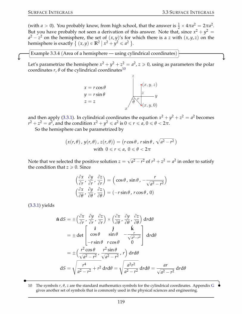
SURFACE INTEGRALS 3.3 SURFACE INTEGRALS
(with a ą 0). You probably know, from high school, that the answer is 12 ˆ 4πa2 = 2πa2.
But you have probably not seen a derivation of this answer. Note that, since x2 + y2 =a2 ´ z2 on the hemisphere, the set of (x, y)’s for which there is a z with (x, y, z) on thehemisphere is exactly
(x, y) P R2
ˇx2 + y2 ď a2 (.
Example 3.3.4 (Area of a hemisphere — using cylindrical coordinates)
Let’s parametrize the hemisphere x2 + y2 + z2 = a2, z ě 0, using as parameters the polarcoordinates r, θ of the cylindrical coordinates10
x = r cos θ
y = r sin θ
z = z
px, y, zq
px, y, 0qy
z
x
z
rθ
and then apply (3.3.1). In cylindrical coordinates the equation x2 + y2 + z2 = a2 becomesr2 + z2 = a2, and the condition x2 + y2 ď a2 is 0 ď r ď a, 0 ď θ ă 2π.
So the hemisphere can be parametrized by(x(r, θ) , y(r, θ) , z(r, θ)
)=(r cos θ , r sin θ ,
aa2 ´ r2
)with 0 ď r ď a, 0 ď θ ă 2π
Note that we selected the positive solution z =?
a2 ´ r2 of r2 + z2 = a2 in order to satisfythe condition that z ě 0. Since(Bx
Br,ByBr
,BzBr
)=(
cos θ , sin θ , ´ r?a2 ´ r2
)(BxBθ
,ByBθ
,BzBθ
)= (´r sin θ , r cos θ , 0)
(3.3.1) yields
n dS = ˘(BxBr
,ByBr
,BzBr
)ˆ(BxBθ
,ByBθ
,BzBθ
)drdθ
= ˘det
ııı kcos θ sin θ ´ r?
a2´r2
´r sin θ r cos θ 0
drdθ
= ˘( r2 cos θ?
a2 ´ r2,
r2 sin θ?a2 ´ r2
, r)
drdθ
dS =
dr4
a2 ´ r2 + r2 drdθ =
da2r2
a2 ´ r2 drdθ =ar?
a2 ´ r2drdθ
10 The symbols r, θ, z are the standard mathematics symbols for the cylindrical coordinates. Appendix Ggives another set of symbols that is commonly used in the physical sciences and engineering.
119

SURFACE INTEGRALS 3.3 SURFACE INTEGRALS
So the area of the hemisphere isż a
0dr
ż 2π
0dθ
ar?a2 ´ r2
= 2πaż a
0dr
r?a2 ´ r2
= 2πaż 0
a2
´du/2?u
with u = a2 ´ r2, du = ´2r dr
= 2πa[´?u
]0
a2
= 2πa2
as it should be.Example 3.3.4
Example 3.3.5 (Area of a hemisphere — using an implicit equation)
This time we’ll compute the area of the hemisphere by using that, if (x, y, z) is on the hemi-sphere, then G(x, y, z) = a2 with G(x, y, z) = x2 + y2 + z2. Since
∇∇∇G(x, y, z) =(2x , 2y , 2z
)(3.3.3) yields
dS =
ˇˇ ∇∇∇G
(x, y, z
)∇∇∇G
(x, y, z
) ¨ kˇˇ dxdy
=
ˇˇ(2x , 2y , 2z
)2z
ˇˇ dxdy
=
ax2 + y2 + z2
|z| dxdy
=aa
a2 ´ x2 ´ y2dxdy on x2 + y2 + z2 = a2
So the area isť
x2+y2ďa2a?
a2´x2´y2 dxdy. To evaluate this integral, we switch to polar
coordinates, substituting x = r cos θ, y = r sin θ. This gives
area =
ij
x2+y2ďa2
aaa2 ´ x2 ´ y2
dxdy =
ż a
0dr r
ż 2π
0dθ
a?a2 ´ r2
= 2πaż a
0dr
r?a2 ´ r2
We already showed, in Example 3.3.4, that the value of this integral is 2πa2.Example 3.3.5
Example 3.3.6 (Area of a hemisphere — using spherical coordinates)
Of course “integrating over a sphere” cries out for spherical coordinates. So this time we
120

SURFACE INTEGRALS 3.3 SURFACE INTEGRALS
parametrize the hemisphere x2 + y2 + z2 = a2, z ě 0, using as parameters the angularcoordinates θ, ϕ of the spherical coordinates
x = ρ sin ϕ cos θ
y = ρ sin ϕ sin θ
z = ρ cos ϕ
z
y
x
p0, 0, zq
px, y, 0qpx, 0, 0q θ
ϕ
px, y, zqρ
ρ sinϕ
ρ cosϕ
ρ sinϕ sin θ
and then apply (3.3.1). In spherical coordinates the equation x2 + y2 + z2 = a2 becomesjust ρ2 = a2, and the condition z ě 0 is 0 ď ϕ ď π
2 , 0 ď θ ă 2π. So the hemisphere can beparametrized11 by(
x(θ, ϕ) , y(θ, ϕ) , z(θ, ϕ))=(a sin ϕ cos θ , a sin ϕ sin θ , a cos ϕ
)0 ď ϕ ď π
2, 0 ď θ ă 2π
Since (BxBθ
,ByBθ
,BzBθ
)=(´ a sin ϕ sin θ , a sin ϕ cos θ , 0
)( BxBϕ
,ByBϕ
,BzBϕ
)= (a cos ϕ cos θ , a cos ϕ sin θ , ´a sin ϕ)
(3.3.1) yields
n dS = ˘(BxBθ
,ByBθ
,BzBθ
)ˆ( BxBϕ
,ByBϕ
,BzBϕ
)dθdϕ
= ˘(´ a sin ϕ sin θ , a sin ϕ cos θ , 0)ˆ (a cos ϕ cos θ , a cos ϕ sin θ , ´a sin ϕ) dθdϕ
= ˘(´ a2 sin2 ϕ cos θ , ´a2 sin2 ϕ sin θ , ´a2 sin ϕ cos ϕ)
dθdϕ
= ¯a2 sin ϕ(
sin ϕ cos θ , sin ϕ sin θ , cos ϕ)
dθdϕ
dS = a2 sin ϕ
bsin2 ϕ cos2 θ + sin2 ϕ sin2 θ + cos2 ϕ dθdϕ
= a2 sin ϕ dθdϕ
So the area of the hemisphere is
a2ż π
2
0dϕ
ż 2π
0dθ sin ϕ = 2πa2
ż π2
0dϕ sin ϕ = 2πa2
[´ cos ϕ
]π/2
0
= 2πa2
11 As we have noted before, the spherical coordinate system really breaks down at ϕ = 0, because ρ = 1,ϕ = 0 gives the same point, namely the north pole (0, 0, 1), for all values of θ. We should really treat ourintegral like an improper integral, first integrating over ε ă ϕ ď π
2 and then taking the limit ε Ñ 0+.However the breakdown of the spherical coordinate system at ϕ = 0, just like the breakdown of polarcoordinates at r = 0, rarely causes problem and it is routine to skip the “improper integral” step.
121

SURFACE INTEGRALS 3.3 SURFACE INTEGRALS
Example 3.3.6
There is an easier way to do this, using a little geometry.
Example 3.3.7 (Area of a hemisphere — using spherical coordinates again)
We are now going to again compute the surface area of the hemisphere using spherical co-ordinates. But this time instead of determining dS using the canned formula (3.3.1), weare going to read it off of a sketch.
Sketch the part of the hemisphere that is in the first octant, x ě 0, y ě 0, z ě 0. Slice itup into small pieces by drawing in curves of constant θ (the blue lines in the figure below)and curves of constant ϕ (the red lines in the figure below). Each piece is approximately
z
y
x
a dϕ
a sinϕdθ
a little rectangle. Concentrate on one of them, like the piece with the thick sides in thefigure above. The area, dS, of that piece is (essentially) the product of its height and itswidth. Each of the two sides of the piece is
˝ a segment of a circle of radius a (a fat blue line in both the figure above and in thefigure on the left below)
˝ that subtends an angle dϕ
˝ and hence is the fraction dϕ2π of a full circle of radius a and hence is of length dϕ
2π 2πa =adϕ.
The top of the piece is
˝ a segment of a circle of radius a sin ϕ (a fat red line in both the figure above and inthe figure on the right below)
˝ that subtends an angle dθ
˝ and hence is the fraction dθ2π of a full circle of radius a sin ϕ and hence is of length
dθ2π 2πa sin ϕ = a sin ϕdθ.
These are drawn in the figure below.
122

SURFACE INTEGRALS 3.3 SURFACE INTEGRALS
z
y
x
a dϕa
ϕ dϕ
z
y
x
a sinϕ
ϕ a
dθ
a sinϕdθ
So the area of our piece is
dS =(adϕ
)(a sin ϕdθ
)= a2 sin ϕ dθdϕ
This is exactly the same formula that we found for dS in Example 3.3.6 so that we will, yetagain, get that the area of a hemisphere of radius a is 2πa2. (Phew!)
Example 3.3.7
But wait! We can do it again, by yet another method!
Example 3.3.8 (Area of a hemisphere — using z = f (x, y))
We’ll compute the area of the hemisphere one last time12. This time we’ll use that theequation of the hemisphere is
z = f (x, y) =b
a2 ´ x2 ´ y2 with (x, y) running over x2 + y2 ď a2
So (3.3.2) yields
dS =b
1 + fx(x, y)2 + fy(x, y)2 dxdy
=
d1 +
( ´xaa2 ´ x2 ´ y2
)2+( ´ya
a2 ´ x2 ´ y2
)2dxdy
=
d1 +
x2 + y2
a2 ´ x2 ´ y2 dxdy
=
da2
a2 ´ x2 ´ y2 dxdy
So the area isť
x2+y2ďa2a?
a2´x2´y2 dxdy. We already found, in Example 3.3.5, that the
value of this integral in 2πa2.
12 We promise!
123
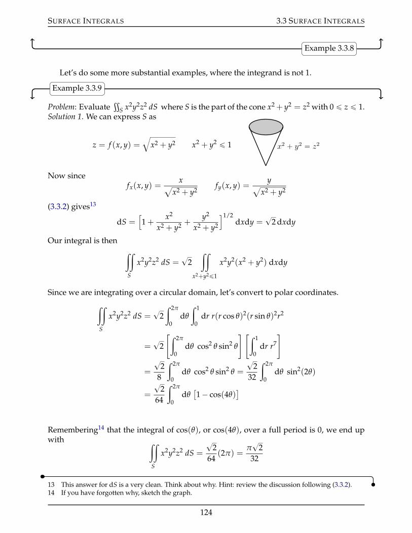
SURFACE INTEGRALS 3.3 SURFACE INTEGRALS
Example 3.3.8
Let’s do some more substantial examples, where the integrand is not 1.
Example 3.3.9
Problem: Evaluateť
S x2y2z2 dS where S is the part of the cone x2 + y2 = z2 with 0 ď z ď 1.Solution 1. We can express S as
z = f (x, y) =b
x2 + y2 x2 + y2 ď 1 x2 ` y2 “ z2
Now sincefx(x, y) =
xax2 + y2
fy(x, y) =ya
x2 + y2
(3.3.2) gives13
dS =[1 +
x2
x2 + y2 +y2
x2 + y2
]1/2dxdy =
?2 dxdy
Our integral is thenij
S
x2y2z2 dS =?
2ij
x2+y2ď1
x2y2(x2 + y2) dxdy
Since we are integrating over a circular domain, let’s convert to polar coordinates.
ij
S
x2y2z2 dS =?
2ż 2π
0dθ
ż 1
0dr r(r cos θ)2(r sin θ)2r2
=?
2
[ż 2π
0dθ cos2 θ sin2 θ
] [ż 1
0dr r7
]
=
?2
8
ż 2π
0dθ cos2 θ sin2 θ =
?2
32
ż 2π
0dθ sin2(2θ)
=
?2
64
ż 2π
0dθ[1´ cos(4θ)
]
Remembering14 that the integral of cos(θ), or cos(4θ), over a full period is 0, we end upwith ij
S
x2y2z2 dS =
?2
64(2π) =
π?
232
13 This answer for dS is a very clean. Think about why. Hint: review the discussion following (3.3.2).14 If you have forgotten why, sketch the graph.
124

SURFACE INTEGRALS 3.3 SURFACE INTEGRALS
Solution 2. We may parametrize15 the cone by
r(z, θ) = z cos θ ııı + z sin θ + z k 0 ď z ď 1, 0 ď θ ď 2π
Then because
BrBz
= cos θ ııı + sin θ + k andBrBθ
= ´z sin θ ııı + z cos θ
(3.3.1) yields16
n dS = ˘det
ııı kcos θ sin θ 1´z sin θ z cos θ 0
dzdθ
= ˘[´ z cos θ ııı´ z sin θ + z k]
dzdθ
dS =?
2z dzdθ
So our integral becomes
ij
S
x2y2z2 dS =?
2ż 2π
0dθ
ż 1
0dz z(z cos θ)2(z sin θ)2z2
=?
2ż 2π
0dθ
ż 1
0dz z7 cos2 θ sin2 θ
=
?2
8
ż 2π
0dθ cos2 θ sin2 θ
We evaluated this integral in Solution 1. So againij
S
x2y2z2 dS =π?
232
Example 3.3.9
Let’s do something more celestial.
Example 3.3.10
Consider a spherical shell of radius a with mass density µ per unit area. Think of it as ahollow planet17. We are going to determine the gravitational force that it exerts on a parti-cle of mass m a distance b away from its centre. This particle can be either outside the shell(b ą a) or inside the shell (b ă a). We can choose the coordinate system so that the centreof the shell is at the origin and the particle is at (0, 0, b). By Newton’s law of gravitation,
15 We did so previously, with different variable names, in Example 3.2.2.16 Again the formula for dS is very neat. Think about why.17 A favourite of science fiction and fantasy writers. Plug “subterranean fiction” into your favourite search
engine. While you’re at it, also try “gravity train”. We’ll look at it in the optional Example 3.3.11.
125

SURFACE INTEGRALS 3.3 SURFACE INTEGRALS
the force exerted on the particle by a tiny piece of the shell of surface area dS located at ris
G (µdS)m|r´ (0, 0, b)|3 (r´ (0, 0, b))
Here G is the gravitational constant, µdS is the mass of the tiny piece of shell, m is themass of the particle and r´ (0, 0, b) is the vector from the particle to the piece of shell. If
dS
p0, 0, bq
r
r ´ p0, 0, bqdS
p0, 0, bq r
r ´ p0, 0, bq
we work in spherical coordinates, as we did in Example 3.3.6,
dS = a2 sin ϕ dϕdθ
and
r = a sin ϕ cos θ ııı + a sin ϕ sin θ + a cos ϕ k
r´ (0, 0, b) = a sin ϕ cos θ ııı + a sin ϕ sin θ + (a cos ϕ´ b) k
|r´ (0, 0, b)|2 = a2 + b2 ´ 2ab cos ϕ
The total force is then
F = Gµma2ż π
0dϕ
ż 2π
0dθ sin ϕ
a sin ϕ cos θ ııı + a sin ϕ sin θ + (a cos ϕ´ b) k[a2 + b2 ´ 2ab cos ϕ
]3/2
Note for future reference that the square root in [a2 + b2´2ab cos ϕ]3/2 is the positive squareroot because [b2 + a2 ´ 2ab cos ϕ]1/2 is the length of r´ (0, 0, b), which is positive.
This integral is a little different than other integrals that we have encountered so far inthat the integrand is a vector. By definition18,
ij
S
[G1 ııı + G2 + G3 k
]dS = ııı
ij
S
G1 dS +
ij
S
G2 dS + kij
S
G3 dS
so we just have to compute the three components separately.
18 Under this definition we still haveť(A + B)dS =
ťA dS +
ťB dS.
126

SURFACE INTEGRALS 3.3 SURFACE INTEGRALS
In our case, the ııı and components
F ¨ ııı = Gµma2ż π
0dϕ
[sin ϕ
a sin ϕ[a2 + b2 ´ 2ab cos ϕ
]3/2
ż 2π
0dθ cos θ
]
F ¨ = Gµma2ż π
0dϕ
[sin ϕ
a sin ϕ[a2 + b2 ´ 2ab cos ϕ
]3/2
ż 2π
0dθ sin θ
]
are both zero19 becauseş2π
0 cos θ dθ =ş2π
0 sin θ dθ = 0 so that
F = Gµma2kż π
0dϕ
ż 2π
0dθ sin ϕ
a cos ϕ´ b[a2 + b2 ´ 2ab cos ϕ
]3/2
= 2πGµma2kż π
0dϕ sin ϕ
a cos ϕ´ b[a2 + b2 ´ 2ab cos ϕ
]3/2
To evaluate this integral we substitute
u = a2 + b2 ´ 2ab cos ϕ du = 2ab sin ϕ dϕ cos ϕ =a2 + b2 ´ u
2ab
When ϕ = 0, u = (a´ b)2 and when ϕ = π, u = (a + b)2, so
F =πGµma
bkż (a+b)2
(a´b)2du
a2+b2´u2b ´ bu3/2
=πGµma
bkż (a+b)2
(a´b)2du
a2´b2´u2b
u3/2
=πGµma
bk[( a2 ´ b2
2b
)u´1/2
´1/2´( 1
2b
)u1/2
1/2
](a+b)2
(a´b)2
Recalling that u1/2 is the positive square root,
F =πGµma
bk[(b2 ´ a2
b
) 1a + b
´ a + bb
´(b2 ´ a2
b
) 1|a´ b| +
|a´ b|b
]If b ą a, so that |a´ b| = b´ a
F =πGµma
bk[b´ a
b´ a + b
b´ a + b
b+
b´ ab
]= ´G(4πa2µ)m
b2 k
If b ă a, so that |a´ b| = a´ b
F =πGµma
bk[b´ a
b´ a + b
b+
a + bb
+a´ b
b
]= 0
The moral20 is
19 Think about why the ııı and components should both be zero. Think symmetry.20 These two results appeared in Isaac Newton’s Principia Mathematica (1687). They are known as New-
ton’s “superb theorems”.
127

SURFACE INTEGRALS 3.3 SURFACE INTEGRALS
˝ if the particle is inside the shell, it feels no gravitational force at all, and
˝ if the particle is outside the shell, it feels the same gravitational force as it would ifthe entire mass of the shell (4πa2µ) were concentrated at the centre of the shell.
Example 3.3.10
Example 3.3.11 (Optional — Gravity Train)
The “Gravity Train21” refers to the following curious, though admittedly not very practi-cal, thought experiment.
• Pretend that the Earth is a perfect sphere of radius R and that it has a constant massdensity ρ.
• Pick any two distinct points on the surface of the Earth. Call them V and M.
• Bore a tunnel straight through the Earth from V to M.
• Place a train in the tunnel at V. Assume that the only forces acting on the train aregravity, G, and a normal force, N, that the tunnel imposes on the train to keep itin the tunnel. In particular, there are no frictional forces, like air resistance, and thetrain does not have an engine. Release the train and assume that it does not melt asit passes through the centre of the Earth.
VM
OG
N
What happens?We’ll simplify our analysis of the motion of the train by picking a convenient coordi-
nate system.
˝ First translate our coordinate system so that the centre of the Earth, call it O, is at theorigin, (0, 0, 0).
˝ Then rotate our coordinate system about the origin so that the origin, V and M alllie in the xz-plane.
21 The British physicist and architect (he was Surveyor to the City of London and chief assistant to Christo-pher Wren) Robert Hooke (1635–1703) wrote about the gravity train idea in a letter to Isaac Newton. Agravity train was used in the 2012 movie Total Recall.
128

SURFACE INTEGRALS 3.3 SURFACE INTEGRALS
˝ Then rotate our coordinate system about the y-axis so that V and M have the same z-coordinate Z ě 0. So the coordinates of V and M are
(˘?R2 ´ Z2 , 0 , Z). Let’s sup-
pose that V is at(?
R2 ´ Z2 , 0 , Z)
and M is at(´?R2 ´ Z2 , 0 , Z
). It really doesn’t
matter which is which, but we can always arrange that it is V at(+?
R2 ´ Z2 , 0 , Z)
by rotating around the z-axis by 180˝ if necessary.
p?R2 ´ Z2 , 0 , Zqp´?
R2 ´ Z2 , 0 , Zq
p0, 0, 0q x
z
G
N
The y- and z-coordinates of the train are always fixed at 0 and Z, respectively. So let’s callthe x-coordinate at time t x(t), and look at the x-component of Newton’s law of motion.
ma = G + N
It ismx2(t) = G ¨ ııı
because the normal force N has no ııı component. Recall that Newton’s law of gravity saysthat
G = ´GMm|r|3 r
where G is the gravitational constant, r is the vector from O to the train, and m is the massof the train. In this case, because of our computation in Example 3.3.10, the train only feelsgravity from shells of the Earth that are inside the train, so that M is the mass of the part
|r|x
z
G
129

SURFACE INTEGRALS 3.3 SURFACE INTEGRALS
of the Earth whose distance to the centre of the Earth is no more than |r|. So
M =43
π|r|3ρ
and
mx2(t) = ´Gm|r|3
43
π|r|3ρ r ¨ ııı
so that
x2(t) +4πGρ
3x(t) = 0
This is exactly the differential equation of simple harmonic motion. We have seen it beforein Example 2.2.7. Except for the constant 4πGρ
3 , it is identical to the equation solved in Ex-ample I.4 of the Appendix I, entitled “Review of Linear Ordinary Differential Equations”.The general solution is
x(t) = C1 cos
(c4πGρ
3t
)+ C2 sin
(c4πGρ
3t
)
with C1 and C2 being arbitrary constants. If we release the train, from rest, at t = 0, thenx(0) =
?R2 ´ Z2 and x1(0) = 0 so that C1 =
?R2 ´ Z2, C2 = 0 and
x(t) =a
R2 ´ Z2 cos
(c4πGρ
3t
)
The train reaches M when x(t) = ´?R2 ´ Z2. That is, when cos(b
4πGρ3 t
)= ´1. So the
transit time, T, from V to M obeys
c4πGρ
3T = π ùñ T = π
d3
4πGρ=
d3π
4Gρ
Notice that this transit time depends only on the gravitational constant G and the densityof the Earth ρ. In particular it is completely independent of
˝ where V and M are and, in particular,˝ how close together V and M are, and also of˝ the radius of the Earth.
In the case of the Earth, the transit time is about 42 minutes.Example 3.3.11
3.3.5 §§ Optional — Dropping Higher Order Terms in du, dv
In the course of deriving (3.3.1), that is, ndS and dS formulae for
130

SURFACE INTEGRALS 3.3 SURFACE INTEGRALS
P0
P1
P3P2
u varyingv“v0
u varyingv“v0`dv
u“u0`duv varying
u“u0v varying
we approximated, for example, the vectors
ÝÝÑP0P1 = r(u0 + du, v0)´ r(u0 , v0)=BrBu
(u0 , v0)du + E1 « BrBu
(u0 , v0)du
ÝÝÑP0P2 = r(u0, v0 + dv)´ r(u0 , v0) =BrBv
(u0 , v0)dv + E2 « BrBv
(u0 , v0)dv
where E1 is bounded22 by a constant times du2 and E2 is bounded by a constant times dv2.That is, we assumed that we could just drop E1 and E2.
So we approximated
ˇÝÝÑP0P1 ˆÝÝÑP0P2ˇ=
ˇˇ[ BrBu
(u0 , v0)du + E1
]ˆ[ BrBv
(u0 , v0)dv + E2
]ˇˇ
=ˇˇ BrBu
(u0 , v0)duˆ BrBv
(u0 , v0)dv + E3
ˇˇ
«ˇˇ BrBu
(u0 , v0)duˆ BrBv
(u0 , v0)dvˇˇ
where the length of the vector E3 is bounded by a constant times du2 dv + du dv2. We’llnow see why dropping terms like E3 does not change the value of the integral at all23.
Suppose that our domain of integration consists of all (u, v)’s in a rectangle of widthA and height B, as in the figure below. Subdivide the rectangle into a grid of n ˆ n
u
v
du
A
dv
B
small subrectangles by drawing lines of constant v (the red lines in the figure) and lines of
22 Remember the error in the Taylor polynomial approximations.23 See the optional §1.1.6 of the CLP-2 text for an analogous argument concerning Riemann sums.
131

SURFACE INTEGRALS 3.4 INTERPRETATION OF FLUX INTEGRALS
constant v (the blue lines in the figure). Each subrectangle has width du = An and height
dv = Bn . Now suppose that in setting up the integral we make, for each subrectangle, an
error that is bounded by some constant times
du2 dv + du dv2 =(A
n
)2 Bn+
An
(Bn
)2=
AB(A + B)n3
Because there are a total of n2 subrectangles, the total error that we have introduced, forall of these subrectangles, is no larger than a constant times
n2 ˆ AB(A + B)n3 =
AB(A + B)n
When we define our integral by taking the limit n Ñ 0 of the Riemann sums, this errorconverges to exactly 0.
3.4IJ Interpretation of Flux Integrals
We defined, in §3.3, two types of integrals over surfaces. We have seen, in §3.3.4, someapplications that lead to integrals of the type
ťS ρ dS. We now look at one application that
leads to integrals of the typeť
S F ¨ n dS. Recall that integrals of this type are called fluxintegrals. Imagine a fluid with
• the density of the fluid (say in kilograms per cubic meter) at position (x, y, z) andtime t being ρ(x, y, z, t) and with
• the velocity of the fluid (say in meters per second) at position (x, y, z) and time tbeing v(x, y, z, t).
We are going to determine the rate (say in kilograms per second) at which the fluid isflowing through a tiny piece dS of surface at (x, y, z). During a tiny time interval of lengthdt about time t, fluid near dS moves v(x, y, z, t)dt. The green line in the figure below is aside view of dS and n = n(x, y, z) is a unit normal vector to dS. So during that tiny time
vdt
vdt
vdt
vdt
n
θ
interval
˝ the red line moves to the green line and˝ the green line moves to the blue line so that˝ the fluid filling the dark grey region below the green line crosses through dS and
moves to light grey region above the green line.
132

SURFACE INTEGRALS 3.4 INTERPRETATION OF FLUX INTEGRALS
If we denote by θ the angle between n and vdt,
˝ the volume of fluid that crosses through dS during the time interval dt is the volumewhose side view is the dark grey region below the green line. This region has basedS and height |vdt| cos θ and so has volume
|v(x, y, z, t)dt| cos θ dS = v(x, y, z, t) ¨ n(x, y, z)dt dS
because n(x, y, z) has length one.˝ The mass of fluid that crosses dS during the time interval dt is then
ρ(x, y, z, t)v(x, y, z, t) ¨ n(x, y, z)dt dS
˝ and the rate at which fluid is crossing through dS is
ρ(x, y, z, t)v(x, y, z, t) ¨ n(x, y, z)dS
Integrating dS over a surface S, we conclude that
The rate at which fluid mass is crossing through a surface S is the flux integralij
S
ρ(x, y, z, t)v(x, y, z, t) ¨ n(x, y, z)dS
Here ρ is the density of the fluid, v is the velocity field of the fluid, and n(x, y, z)is a unit normal to S at (x, y, z). If the flux integral is positive the fluid is crossingin the direction n. If it is negative the fluid is crossing opposite to the directionof n. The rate at which volume of fluid is crossing through a surface S is the fluxintegral
ij
S
v(x, y, z, t) ¨ n(x, y, z)dS
Lemma 3.4.1.
3.4.1 §§ Examples of Flux Integrals
Example 3.4.2 (Point Source)
In Example 2.1.2, we found that the vector field of a point source24 (in three dimensions)that creates 4πm liters per second is
v(x, y, z) =m
r(x, y, z)2 r(x, y, z)
24 You can imagine that a very small pipe pumps water to the origin.
133

SURFACE INTEGRALS 3.4 INTERPRETATION OF FLUX INTEGRALS
where
r(x, y, z) =b
x2 + y2 + z2 r(x, y, z) =xııı + y + zka
x2 + y2 + z2
We sketched it in Figure 2.1.1. We’ll now compute the flux of this vector field across asphere centred on the origin. Suppose that the sphere has radius R. Then the outward25
n
pointing normal at a point (x, y, z) on the sphere is
n(x, y, z) = r(x, y, z) =xııı + y + zka
x2 + y2 + z2=
xııı + y + zkR
Note that r(x, y, z) ¨ r(x, y, z) = 1 and that, on the sphere, r(x, y, z) = R. So the flux of voutward through the sphere is
ij
S
v ¨ n dS =
ij
S
mr(x, y, z)2 r(x, y, z) ¨ r(x, y, z) dS
=
ij
S
mR2 dS =
mR2 4πR2
= 4πm
This is the rate at which volume of fluid is exiting the sphere. In our derivation of thevector field we assumed that the fluid is incompressible, so it is also the rate at which thepoint source is creating fluid.
Example 3.4.2
Example 3.4.3 (Vortex)
In Figure 2.1.3, we sketched the vector field (in two dimensions)
v(x, y) = Ω(´ yııı + x
)We’ll now compute the flux of this vector field across a circle C centred on the origin.Suppose that the circle has radius R. By definition, in two dimensions, the flux of a
25 It doesn’t really matter which unit normal we pick here. We just have to be clear which one we’reusing. With the outward normal, the flux gives the rate at which fluid crosses the sphere in the outwarddirection. If we were to use the inward pointing normal, the flux would give the rate at which fluidcrosses the sphere in the inward direction.
134

SURFACE INTEGRALS 3.4 INTERPRETATION OF FLUX INTEGRALS
n
vector field across a curve C isş
C v ¨ n ds.This is the natural analog of the flux in three dimensions — the surface S has been
replaced by the curve C, and the surface area dS of a tiny piece of S has been replaced bythe arc length ds of a tiny piece of C.
The outward pointing unit normal at a point (x, y) on our circle C is
n(x, y) =xııı + yax2 + y2
=xııı + y
R
So
v(x, y) ¨ n(x, y) =ΩR(´ yııı + x
) ¨ (xııı + y)= 0
and the flux across C is ż
Cv ¨ n ds = 0
This should not be a surprise — no fluid is crossing C at all. This is exactly what we wouldexpect from looking at the arrows in Figure 2.1.3 or at the stream lines in Example 2.2.6.
Example 3.4.3
Example 3.4.4
Problem: Evaluateť
S F ¨ n dS where
F(x, y, z) = (x + y) ııı + (y + z) + (x + z) k
and S is the boundary of V = (x, y, z)
ˇ0 ď x2 + y2 ď 9, 0 ď z ď 5
(, and n is the
outward normal26 to S.
Solution. The volume V looks like a tin can of radius 3 and height 5. It is natural to
26 It is necessary that the problem specify, one way or another, whether n is the inward pointing normalor the outward pointing normal. Without this, the meaning of
ťS F ¨ n dS is ambiguous. Think about
where the orientation of the normal vector gets used in your solution.
135

SURFACE INTEGRALS 3.4 INTERPRETATION OF FLUX INTEGRALS
n “ kSt
n “ ´kSb
nSs
decompose its surface S into three parts
St = (x, y, z)
ˇ0 ď x2 + y2 ď 9, z = 5
(= the top
Sb = (x, y, z)
ˇ0 ď x2 + y2 ď 9, z = 0
(= the bottom
Ss = (x, y, z)
ˇx2 + y2 = 9, 0 ď z ď 5
(= the side
We’ll compute the flux through each of the three parts separately and then add themtogether.The Top: On the top, the outward pointing normal to S is n = k and dS = dxdy. This isprobably intuitively obvious. But if it isn’t, you can always derive it by parametrizing thetop by r(x, y) = x ııı + y + 5 k with x2 + y2 ď 9. So the flux through the top is
ij
St
F ¨ n dS =
ij
x2+y2ď9z=5
(x + z) dxdy =
ij
x2+y2ď9
(x + 5) dxdy
The integralť
x2+y2ď9 x dxdy = 0 since x is odd and the domain of integration is symmet-ric about x = 0. So
ij
St
F ¨ n dS =
ij
x2+y2ď9
5 dxdy = 5π(3)2 = 45π
The Bottom: On the bottom, the outward pointing normal to S is n = ´k and dS = dxdy.So the flux through the bottom is
ij
Sb
F ¨ n dS = ´ij
x2+y2ď9z=0
(x + z) dxdy = ´ij
x2+y2ď9
x dxdy = 0
again since x is odd and the domain of integration is symmetric about x = 0.The Side: We can parametrize the side by using cylindrical coordinates.
r(θ, z) =(3 cos θ , 3 sin θ , z
)0 ď θ ă 2π, 0 ď z ď 5
136

SURFACE INTEGRALS 3.4 INTERPRETATION OF FLUX INTEGRALS
Then, using (3.3.1),
BrBθ
= (´3 sin θ , 3 cos θ , 0)
BrBz
= (0 , 0 , 1)
n dS =BrBθˆ BrBz
dθ dz
θ
top view
r
n
= (3 cos θ , 3 sin θ , 0) dθ dz
Note that n = (cos θ , sin θ , 0) is outward pointing27, as desired. Continuing,
F(x(θ, z) , y(θ, z) , z(θ, z)
)= 3(cos θ + sin θ) ııı + (3 sin θ + z) + (3 cos θ + z) k
F ¨ n dS =
9 cos2 θ + 3 sin θ cos θ + 9 sin2 θ + 3z sin θ(
dθ dz
=
9 + 3/2 sin(2θ) + 3z sin θ(
dθ dz
So the flux through the side is
ij
Ss
F ¨ n dS =
ż 2π
0dθ
ż 5
0dz
9 + 3/2 sin(2θ) + 3z sin θ
(
= 9ż 2π
0dθ
ż 5
0dz since
ż 2π
0sin θ dθ =
ż 2π
0sin(2θ)dθ = 0
= 9ˆ 2π ˆ 5 = 90π
and the total flux is
ij
S
F ¨ n dS =
ij
St
F ¨ n dS +
ij
Sb
F ¨ n dS +
ij
Ss
F ¨ n dS = 45π + 0 + 90π = 135π
Example 3.4.4
Example 3.4.5
Problem: Evaluateť
S F ¨ n dS where F(x, y, z) = x4ııı + 2y2 + zk, S is the half of the sur-face 1
4 x2 + 19 y2 + z2 = 1 with z ě 0, and n is the upward pointing unit normal.
27 To check, draw, in your head, a sketch of the top view of the can. “Top view” just means “ignore thez-coordinate”. The top view of the can is a circle of radius 3. Then, at a generic point, r = (cos θ, sin θ),on the can, draw the unit normal n = (cos θ , sin θ) with its tail at r. It is pointing away from the origin,just like r is. That is, n is pointing outward.
137

SURFACE INTEGRALS 3.4 INTERPRETATION OF FLUX INTEGRALS
14x2 ` 1
9y2 ` z2 “ 1
z
y
x
Solution 1. We start by parametrizing the surface, which is half of an ellipsoid. By way ofmotivation for the parametrization, recall that spherical coordinates, with ρ = 1, providea natural way to parametrize the sphere x2 + y2 + z2 = 1. Namely x = cos θ sin ϕ, y =sin θ sin ϕ, z = cos ϕ. The reason that these spherical coordinates work is that the trigidentity cos2 α + sin2 α = 1 implies
x2 + y2 = cos2 θ sin2 ϕ + sin2 θ sin2 ϕ = sin2 ϕ
and then (x2 + y2)+ z2 = sin2 ϕ + cos2 ϕ = 1
The equation of our ellipsoid is (x2
)2+(y
3
)2+ z2 = 1
so we can parametrize the ellipsoid by replacing x with x2 and y with y
3 in our parametriza-tion of the sphere. That is, we choose the parametrization
x(θ, ϕ) = 2 cos θ sin ϕ
y(θ, ϕ) = 3 sin θ sin ϕ
z(θ, ϕ) = cos ϕ
with (θ, ϕ) running over 0 ď θ ď 2π, 0 ď ϕ ď π/2. Note that
14
x(θ, ϕ)2 +19
y(θ, ϕ)2 + z(θ, ϕ)2 = 1
as desired.Then, using (3.3.1),(Bx
Bθ,ByBθ
,BzBθ
)= (´2 sin θ sin ϕ , 3 cos θ sin ϕ , 0)( Bx
Bϕ,ByBϕ
,BzBϕ
)= (2 cos θ cos ϕ , 3 sin θ cos ϕ , ´ sin ϕ)
n dS = ´(BxBθ
,ByBθ
,BzBθ
)ˆ( BxBϕ
,ByBϕ
,BzBϕ
)dθdϕ
= ´(´3 cos θ sin2 ϕ,´2 sin θ sin2 ϕ,´6 sin ϕ cos ϕ)dθdϕ
138

SURFACE INTEGRALS 3.4 INTERPRETATION OF FLUX INTEGRALS
The extra minus sign in n dS was put there to make the z component of n positive. (Theproblem specified that n is to be upward unit normal.) As
F(x(θ, ϕ) , y(θ, ϕ) , z(θ, ϕ)
)= 24 cos4 θ sin4 ϕ ııı + 2ˆ 32 sin2 θ sin2 ϕ + cos ϕ k
we have
F ¨ n dS =[3ˆ 24 cos5 θ sin6 ϕ + 2ˆ 2ˆ 32 sin3 θ sin4 ϕ + 6 sin ϕ cos2 ϕ
]dθ dϕ
and the desired integralij
S
F ¨ n dS =
ż π2
0dϕ
ż 2π
0dθ[3ˆ 24 cos5 θ sin6 ϕ + 2ˆ 2ˆ 32 sin3 θ sin4 ϕ + 6 sin ϕ cos2 ϕ
]Since
ş2π0 cosm θ dθ =
ş2π0 sinm θ dθ = 0 for all odd28 natural numbers m,
ij
S
F ¨ n dS =
ż π/2
0dϕ
ż 2π
0dθ 6 sin ϕ cos2 ϕ = 12π
ż π/2
0dϕ sin ϕ cos2 ϕ = 12π
[´ 1
3cos3 ϕ
]π/2
0
= 4π
The integral was evaluated by guessing (and checking) that ´13 cos3 ϕ is an antiderivative
of sin ϕ cos2 ϕ. It can also be done by substituting u = cos ϕ, du = ´ sin ϕ dϕ.
Solution 2. This time we’ll parametrize the half-ellipsoid using a variant of cylindricalcoordinates.
x(r, θ) = 2r cos θ
y(r, θ) = 3r sin θ
z(r, θ) =a
1´ r2
with (r, θ) running over 0 ď θ ď 2π, 0 ď r ď 1. Because we built the factors of 2 and 3into x(r, θ) and y(r, θ), we have
x(r, θ)2
4+
y(r, θ)2
9= r2 cos2 θ + r2 sin2 θ = r2
ùñ x(r, θ)2
4+
y(r, θ)2
9+ z(r, θ)2 = r2 +
(a1´ r2
)2= 1
as desired. Further z(r, θ) ě 0 by our choice of square root in the definition of z(r, θ).So, using (3.3.1),(Bx
Bθ,ByBθ
,BzBθ
)= (´2r sin θ, 3r cos θ, 0)(Bx
Br,ByBr
,BzBr
)=(
2 cos θ, 3 sin θ,´ r?1´ r2
)ndS = ´
(BxBθ
,ByBθ
,BzBθ
)ˆ(BxBr
,ByBr
,BzBr
)dr dθ
= ´(´ 3r2 cos θ?
1´ r2,´2r2 sin θ?
1´ r2,´6r
)dr dθ
28 Look at the graphs of cosm ϕ and sinm ϕ.
139

SURFACE INTEGRALS 3.4 INTERPRETATION OF FLUX INTEGRALS
Once again, the extra minus sign in ndS was put there to make the z component of npositive. Continuing,
F(x(r, θ) , y(r, θ) , z(r, θ)
)= 24r4 cos4 θ ııı + 2ˆ 32r2 sin2 θ +
a1´ r2 k
F ¨ n dS =[3ˆ 24 r6
?1´ r2
cos5 θ + 2232 r4?
1´ r2sin3 θ + 6r
a1´ r2
]dr dθ
Again using thatş2π
0 cosm θ dθ =ş2π
0 sinm θ dθ = 0 for all odd natural numbers m,ż
SF ¨ n dS =
ż 1
0dr
ż 2π
0dθ 6r
a1´ r2
= 12π
ż 1
0dr r
a1´ r2 = 12π
[´ 1
3(1´ r2)
3/2]1
0
= 4π
The integral was evaluated by guessing (and checking) that´13(1´ r2)
3/2 is an antideriva-tive of r
?1´ r2. It can also be done by substituting u = 1´ r2, du = ´2r dr.
Solution 3. The surface is of the form G(x, y, z) = 0 with G(x, y, z) = 14 x2 + 1
9 y2 + z2 ´ 1.Hence, using (3.3.3),
ndS =∇∇∇G∇∇∇G ¨ kdx dy =
x2 ııı + 2y
9 + 2zk2z
dx dy =( x
4zııı +
y9z
+ k)
dx dy
ùñ F ¨ n dS =(x5
4z+
2y3
9z+ z)
dx dy
It is true that ndS, and consequently F ¨ n dS become infinite29 as z Ñ 0. So we shouldreally treat the integral as an improper integral, first integrating over z ě ε and then takingthe limit ε Ñ 0+. But, as we shall see, the singularity is harmless. So it is standard to gloss
over this point. On S, z = z(x, y) =b
1´ x2
4 ´ y2
9 and x2
4 + y2
9 ď 1, soż
SF ¨ n dS =
ij
x24 +
y29 ď1
( x5
4z(x, y)+
2y3
9z(x, y)+ z(x, y)
)dx dy
Both x5
4z(x,y) and 2y3
9z(x,y) are odd under x Ñ ´x, y Ñ ´y and the domain of integration iseven under x Ñ ´x, y Ñ ´y, so their integrals are zero and
ż
SF ¨ n dS =
ij
x24 +
y29 ď1
z(x, y) dx dy
=
ij
x24 +
y29 ď1
c1´ x2
4´ y2
9dx dy
To evaluate this integral, first make the change of variables30 x = 2X, dx = 2dX, y = 3Y,
29 That’s because the ellipsoid is becoming vertical as z Ñ 0, so that x and y are not really good parametersthere.
30 The reader interested in general changes of variables in multidimensional integrals should look up“Jacobian determinant”.
140

SURFACE INTEGRALS 3.5 ORIENTATION OF SURFACES
dy = 3dY to give ż
SF ¨ n dS =
ij
X2+Y2ď1
a1´ X2 ´Y2 6 dX dY
Then switch to polar coordinates, X = r cos θ, Y = r sin θ, dXdY = r drdθ to giveż
SF ¨ n dS =
ż 1
0dr
ż 2π
0dθ 6r
a1´ r2 = 12π
ż 1
0dr r
a1´ r2 = 12π
[´ 1
3(1´ r2)3/2
]1
0
= 4π
Solution 4. The surface is of the form z = f (x, y) with f (x, y) =b
1´ x2
4 ´ y2
9 . Hence,using (3.3.2),
ndS =[´ B fBx
ııı´ B fBy
+ k]
dx dy =
x4 ııı + y
9 b1´ x2
4 ´ y2
9
+ k
dx dy
ùñ F ¨ n dS =
x5
4 + 2y3
9b1´ x2
4 ´ y2
9
+
c1´ x2
4´ y2
9
dx dy
Note that our unit normal is upward pointing, as required. As in Solution 3, by the odd-ness of the x5 and y3 terms in the integrand,
ż
SF ¨ n dS =
ij
x24 +
y29 ď1
x5
4 + 2y3
9? ¨ ¨ ¨ +
c1´ x2
4´ y2
9
dx dy
=
ij
x24 +
y29 ď1
c1´ x2
4´ y2
9dx dy
Now continue as in Solution 3.Example 3.4.5
3.5IJ Orientation of Surfaces
One thing that made the flux integrals of the last section possible is that we could choosesensible unit normal vectors n. In this section, we explain this more carefully.
Consider the sphere x2 + y2 + z2 = 1. We can think of this surface as having two sides— an inside (the side you see when you are living inside the sphere) and an outside (theside you see when you are living outside the sphere). Concentrate on one point (x0, y0, z0)on the sphere. The surface x2 + y2 + z2 = 1 has precisely two unit normal vectors at(x0, y0, z0), namely
n+ = +(x0, y0, z0) and n´ = ´(x0, y0, z0)
141

SURFACE INTEGRALS 3.5 ORIENTATION OF SURFACES
We can view n+ as being associated to (or attached to) the outside of the sphere and n´ asbeing associated to (or attached to) the inside of the sphere. Note that, as we move overthe sphere, both n+ and n´ change continuously.
An oriented surface is a surface together with a continuous function
N : S Ñ R3
such that, for each point p of S, N(p) is a unit normal to S at p.
Definition 3.5.1.
Example 3.5.2 (Sphere)
One orientation of the sphere S = (x, y, z)
ˇx2 + y2 + z2 = 1
(is
N(x, y, z) = (x, y, z)
It associates to each point p of S the outward pointing unit normal to S at p. We can thinkof S with this orientation as being the outer side of S.
The other orientation of the sphere S = (x, y, z)
ˇx2 + y2 + z2 = 1
(is
N(x, y, z) = ´(x, y, z)
It associates to each point p of S the inward pointing unit normal to S at p. We can thinkof S with this orientation as being the inner side of S.
While this discussion might seem inordinately picky, it turns out that not all surfacescan be oriented. Our next example exhibits one.
Example 3.5.2
Example 3.5.3 (Optional — The Mobius Strip)
There are some surfaces S for which it is not possible to choose a continuous orientationmap N : S Ñ R3. Such surfaces are said to be non-orientable. The most famous non-orientable surface is the Mobius31 strip32, which you can construct as follows. Take arectangular strip of paper. Lay it flat and then introduce a half twist so that the arrow on
31 August Ferdinand Mobius (1790–1868) was a German mathematician and astronomer. He was a de-scendant of Martin Luther and a student of Gauss.
32 Another famous non-orientable surface is the Klein bottle. You can easily find discussions of it usingyour favourite search engine.
142

SURFACE INTEGRALS 3.5 ORIENTATION OF SURFACES
the right hand end points upwards, rather than downwards. Then glue the two ends ofthe strip together, with the two arrows coinciding. That’s the Mobius strip.
Let’s parametrize it. Think of the strip of paper that we used to construct it as consist-ing of a backbone (the horizontal black line in the figure below) with a bunch of ribs (likethe thick blue line in the figure) emanating from it. When we glue the two ends of the
θ
v
ℓ
w
strip together, the black line forms a circle. If the strip has length `, the circle will havecircumference ` and hence radius `
2π . We’ll parametrize it as the circle
`
2πr(θ) where r(θ) = cos(θ) ııı + sin(θ)
This circle is in the xy-plane. It is the black circle in the figure below. (The figure onlyshows the part of the circle in the first octant, i.e. with x, y, z ě 0.) Now we’ll add in the
z
y
xrpθq
k
θℓ2πrpθq
blue ribs. We’ll put the blue rib, that is attached to the backbone at `2π r(θ), in the plane
that contains the vectors r(θ) and k. A side view of the plane that contains the vectorsr(θ) and k is sketched in the figure below. To put the half twist into the strip of paper, we
143

SURFACE INTEGRALS 3.5 ORIENTATION OF SURFACES
upv, θ, ϕq
ℓ2πrpθq rpθq
kϕ
want the blue rib to rotate about the backbone by 180˝, i.e. π radians, as θ runs from 0 to2π. That will be the case if we pick the angle ϕ in the figure to be θ/2. The vector that isrunning along the blue rib in the figure is
u(v, θ, ϕ) = v cos(ϕ) r(θ) + v sin(ϕ) k
where the length, v, of the vector is a parameter. If the width of our original strip of paperis w, then as the parameter v runs from ´w/2 to +w/2, the tip of the vector u(v, θ, ϕ) runsover the entire blue rib. So, choosing ϕ = θ/2, our parametrization of the Mobius strip is
r(θ, v) =`
2πr(θ) + u(v, θ, θ/2)
=`
2πr(θ) + v cos
(θ/2)r(θ) + v sin
(θ/2)k 0 ď θ ă 2π, ´w
2ď v ď w
2
where r(θ) = cos(θ) ııı + sin(θ) .Now that we have parametrized the Mobius strip, let’s return to the question of ori-
entability. Recall, from Definition 3.5.1, that, if the Mobius strip were orientable, therewould exist a continuous function N which assigns to each point r of the strip a unit nor-mal vector N(r) at r. First, we’ll find the normal vectors to the surface using (3.3.1). Thepartial derivatives
BrBθ
(θ, v) =`
2πr1(θ) + v cos
(θ/2)r1(θ)´ v
2sin(
θ/2)r(θ) +
v2
cos(
θ/2)k
BrBv
(θ, v) = cos(
θ/2)r(θ) + sin
(θ/2)k
are relatively messy, so let’s just consider the case v = 0 (i.e. find the normal vectors onthe backbone). Then
BrBθ
(θ, 0) =`
2πr1(θ)
BrBv
(θ, 0) = cos(
θ/2)r(θ) + sin
(θ/2)k
Since
r1(θ)ˆ r(θ) =(´ sin(θ) ııı + cos(θ)
)ˆ ( cos(θ) ııı + sin(θ) )= ´k
r1(θ)ˆ k =(´ sin(θ) ııı + cos(θ)
)ˆ k = r(θ)
we have
BrBθ
(θ, 0)ˆ BrBv
(θ, 0) = ´ `
2π
(cos
(θ/2)
k´ sin(
θ/2)
r(θ))
144

SURFACE INTEGRALS 3.5 ORIENTATION OF SURFACES
As k and r(θ) are mutually perpendicular unit vectors, cos(
θ/2)
k ´ sin(
θ/2)
r(θ) haslength one, and the two unit normal vectors to the Mobius strip at r(θ, 0) are
˘(
cos(
θ/2)
k´ sin(
θ/2)
r(θ))
So, for each θ, N(r(θ, 0)
)must be either
cos(
θ/2)
k´ sin(
θ/2)
r(θ) or ´ ( cos(
θ/2)
k´ sin(
θ/2)
r(θ))
Imagine walking along the Mobius strip. The normal vector N(r(θ, v)
)is our body when
we are at r(θ, v) — our feet are at the tail of the vector N(r(θ, v)
)and our head is at the ar-
row of N(r(θ, v)
). We start walking at r(0, 0) = `
2π ııı. Our body, N(
`2π ııı)= N
(r(0, 0)
)has to
be one of ˘( cos(0) k´ sin(0) r(0))= ˘k. Let’s suppose that N
(r(0, 0)
)= +k. (We start
upright.) Now we start walking along the backbone of the Mobius strip, increasing θ. Be-cause N
(r(θ, 0)
)has to be continuous, N
(r(θ, 0)
)has to be +
(cos
(θ/2)
k´ sin(
θ/2)
r(θ)).
We keep increasing θ. By continuity, N(r(θ, 0)
)has to be +
(cos
(θ/2)
k ´ sin(
θ/2)
r(θ))
for bigger and bigger θ. Eventually we get to θ = 2π, i.e. to
r(2π, 0) =`
2πr(2π) =
`
2πııı =
`
2πr(0) = r(0, 0)
We are back to our starting point. Continuity has forced
N(r(2π, 0)
)= N
(r(θ, 0)
)ˇˇθ=2π
= +(
cos(
θ/2)
k´ sin(
θ/2)
r(θ))ˇˇθ=2π
= ´k
So we have arrived back upside down. That’s a problem — N(r(2π, 0)
)= N
(`
2π ııı)
andwe have already defined N
(`
2π ııı)= +k, not ´k. So the Mobius strip is not orientable. The
interested reader should look up M. C. Escher’s Mobius Strip II (Red Ants).Example 3.5.3
145

INTEGRAL THEOREMS
Chapter 4
4.1IJ Gradient, Divergence and Curl
“Gradient, divergence and curl”, commonly called “grad, div and curl”, refer to a verywidely used family of differential operators and related notations that we’ll get to shortly.We will later see that each has a “physical” significance. But even if they were only short-hand1, they would be worth using.
For example, one of Maxwell’s equations (relating the electric field E and the magneticfield B) written without the use of this notation is
(BE3
By´ BE2
Bz
)ııı´(BE3
Bx´ BE1
Bz
) +(BE2
Bx´ BE1
By
)k = ´1
c
(BB1
Btııı +
BB2
Bt +
BB3
Btk)
The same equation written using this notation is
∇∇∇ˆ E = ´1cBBBt
The shortest way to write (and easiest way to remember) gradient, divergence and curluses the symbol “∇∇∇” which is a differential operator like B
Bx . It is defined by
∇∇∇ = ıııBBx
+ BBy
+ kBBz
and is called “del” or “nabla”. Here are the definitions.
1 Good shorthand is not only more brief, but also aids understanding “of the forest by hiding the trees”.
146

INTEGRAL THEOREMS 4.1 GRADIENT, DIVERGENCE AND CURL
(a) The gradient of a scalar-valued function f (x, y, z) is the vector field
grad f =∇∇∇ f =B fBx
ııı +B fBy
+B fBz
k
Note that the input, f , for the gradient is a scalar-valued function, while theoutput,∇∇∇ f , is a vector-valued function.
(b) The divergence of a vector field F(x, y, z) is the scalar-valued function
div F =∇∇∇ ¨ F =BF1
Bx+BF2
By+BF3
Bz
Note that the input, F, for the divergence is a vector-valued function, whilethe output,∇∇∇ ¨ F, is a scalar-valued function.
(c) The curl of a vector field F(x, y, z) is the vector field
curl F =∇∇∇ˆ F =(BF3
By´ BF2
Bz
)ııı´(BF3
Bx´ BF1
Bz
) +(BF2
Bx´ BF1
By
)k
Note that the input, F, for the curl is a vector-valued function, and the output,∇∇∇ˆ F, is a again a vector-valued function.
(d) The Laplacian2 of a scalar-valued function f (x, y, z) is the scalar-valued func-tion
∆ f =∇∇∇2 f =∇∇∇ ¨∇∇∇ f =B2 fBx2 +
B2 fBy2 +
B2 fBz2
The Laplacian of a vector field F(x, y, z) is the vector field
∆F =∇∇∇2F =∇∇∇ ¨∇∇∇F =B2FBx2 +
B2FBy2 +
B2FBz2
Note that the Laplacian maps either a scalar-valued function to a scalar-valued function, or a vector-valued function to a vector-valued function.
Definition 4.1.1.
The gradient, divergence and Laplacian all have obvious generalizations to dimensionsother than three. That is not the case for the curl. It does have a, far from obvious, gener-alization, which uses differential forms. Differential forms are well beyond our scope, butare introduced in the optional §4.7.
Example 4.1.2
2 Pierre-Simon Laplace (1749–1827) was a French mathematician and astronomer. He is also the Laplaceof Laplace’s equation, the Laplace transform, and the Laplace-Bayes estimator. He was Napoleon’sexaminer when Napoleon attended the Ecole Militaire in Paris.
147

INTEGRAL THEOREMS 4.1 GRADIENT, DIVERGENCE AND CURL
As an example of an application in which both the divergence and curl appear, we haveMaxwell’s equations3 4 5, which form the foundation of classical electromagnetism.
∇∇∇ ¨ E = 4πρ
∇∇∇ ¨ B = 0
∇∇∇ˆ E +1cBBBt
= 0
∇∇∇ˆ B´ 1cBBBt
=4π
cJ
Here E is the electric field, B is the magnetic field, ρ is the charge density, J is the currentdensity and c is the speed of light.
Example 4.1.2
4.1.1 §§ Vector Identities
Two computationally extremely important properties of the derivative ddx are linearity and
the product rule.ddx(a f (x) + bg(x)
)= a
d fdx
(x) + bdgdx
(x)
ddx(
f (x) g(x))=
d fdx
(x) g(x) + f (x)dgdx
(x)
Gradient, divergence and curl also have properties like these, which indeed stem (ofteneasily) from them. First, here are the statements of a bunch of them. (A memory aid andproofs will come later.) In fact, here are a very large number of them. Many are includedjust for completeness. Only a relatively small number are used a lot. They are in red.
(a) ∇∇∇( f + g) =∇∇∇ f +∇∇∇g
(b) ∇∇∇(c f ) = c∇∇∇ f , for any constant c
(c) ∇∇∇( f g) = (∇∇∇ f )g + f (∇∇∇g)
(d) ∇∇∇( f /g) =(
g∇∇∇ f ´ f ∇∇∇g)/g2 at points x where g(x) ‰ 0.
(e) ∇∇∇(F ¨G) = Fˆ (∇∇∇ˆG)´ (∇∇∇ˆ F)ˆG + (G ¨∇∇∇)F + (F ¨∇∇∇)GHere6
(G ¨∇∇∇)F = G1BFBx
+ G2BFBy
+ G3BFBz
Theorem 4.1.3 (Gradient Identities).
3 To be picky, these are Maxwell’s equations in the absence of a material medium and in Gaussian units.4 One important consequence of Maxwell’s equations is that electromagnetic radiation, like light, propa-
gate at the speed of light.5 James Clerk Maxwell (1831–1879) was a Scottish mathematical physicist. In a poll of prominent physi-
cists, Maxwell was voted the third greatest physicist of all time. Only Newton and Einstein beat him.
148

INTEGRAL THEOREMS 4.1 GRADIENT, DIVERGENCE AND CURL
(a) ∇∇∇ ¨ (F + G) =∇∇∇ ¨ F +∇∇∇ ¨G(b) ∇∇∇ ¨ (cF) = c∇∇∇ ¨ F, for any constant c
(c) ∇∇∇ ¨ ( f F) = (∇∇∇ f ) ¨ F + f ∇∇∇ ¨ F(d) ∇∇∇ ¨ (FˆG) = (∇∇∇ˆ F) ¨G´ F ¨ (∇∇∇ˆG)
Theorem 4.1.4 (Divergence Identities).
(a) ∇∇∇ˆ (F + G) =∇∇∇ˆ F +∇∇∇ˆG
(b) ∇∇∇ˆ (cF) = c∇∇∇ˆ F, for any constant c
(c) ∇∇∇ˆ ( f F) = (∇∇∇ f )ˆ F + f ∇∇∇ˆ F
(d) ∇∇∇ˆ (FˆG) = F(∇∇∇ ¨G)´ (∇∇∇ ¨ F)G + (G ¨∇∇∇)F´ (F ¨∇∇∇)GHere
(G ¨∇∇∇)F = G1BFBx
+ G2BFBy
+ G3BFBz
Theorem 4.1.5 (Curl Identities).
(a) ∇∇∇2( f + g) =∇∇∇2 f +∇∇∇2g
(b) ∇∇∇2(c f ) = c∇∇∇2 f , for any constant c
(c) ∇∇∇2( f g) = f ∇∇∇2g + 2∇∇∇ f ¨∇∇∇g + g∇∇∇2 f
Theorem 4.1.6 (Laplacian Identities).
(a) ∇∇∇ ¨ (∇∇∇ˆ F) = 0 (divergence of curl)
(b) ∇∇∇ˆ (∇∇∇ f ) = 0 (curl of gradient)
(c) ∇∇∇ ¨ ( f t∇∇∇gˆ∇∇∇hu) =∇∇∇ f ¨ (∇∇∇gˆ∇∇∇h)
(d) ∇∇∇ ¨ ( f∇∇∇g´ g∇∇∇ f ) = f ∇∇∇2g´ g∇∇∇2 f
(e) ∇∇∇ˆ (∇∇∇ˆ F) =∇∇∇(∇∇∇ ¨ F)´∇∇∇2F (curl of curl)
Theorem 4.1.7 (Degree Two Identities).
6 This is really the only definition that makes sense. For example G ¨ (∇∇∇F) does not make sense becauseyou can’t take the gradient of a vector-valued function.
149

INTEGRAL THEOREMS 4.1 GRADIENT, DIVERGENCE AND CURL
Memory Aid. Most of the vector identities (in fact all of them except Theorem 4.1.3.e, The-orem 4.1.5.d and Theorem 4.1.7) are really easy to guess. Just combine the conventionallinearity and product rules with the facts that
˝ if the left hand side is a vector (scalar), then the right hand side must also be a vector(scalar) and
˝ the only valid products of two vectors are the dot and cross products and˝ the product of a scalar with either a scalar or a vector cannot be either a dot or cross
product and˝ Aˆ B = ´BˆA. (The cross product is antisymmetric.)
For example, consider Theorem 4.1.4.c, which says∇∇∇ ¨ ( f F) = (∇∇∇ f ) ¨ F + f ∇∇∇ ¨ F.
˝ The left hand side,∇∇∇ ¨ ( f F), is a scalar, so the right hand side must also be a scalar.˝ The left hand side, ∇∇∇ ¨ ( f F), is a derivative of the product of f and F, so, mimick-
ing the product rule, the right hand side will be a sum of two terms, one with Fmultiplying a derivative of f , and one with f multiplying a derivative of F.
˝ The derivative acting on f must be∇∇∇ f , because∇∇∇ ¨ f and∇∇∇ˆ f are not well-defined.To end up with a scalar, rather than a vector, we must take the dot product of ∇∇∇ fand F. So that term is (∇∇∇ f ) ¨ F.
˝ The derivative acting on F must be either∇∇∇ ¨ F or∇∇∇ˆ F. We also need to multiplyby the scalar f and end up with a scalar. So the derivative must be a scalar, i.e. ∇∇∇ ¨ Fand that term is f t∇∇∇ ¨ Fu.
˝ Our final guess is∇∇∇ ¨ ( f F) = (∇∇∇ f ) ¨ F + f ∇∇∇ ¨ F, which, thankfully, is correct.
Proof of Theorems 4.1.3, 4.1.4, 4.1.5, 4.1.6 and 4.1.7. All of the proofs (except for those of The-orem 4.1.7.c,d, which we will return to later) consist of
˝ writing out the definition of the left hand side and˝ writing out the definition of the right hand side and˝ observing (possibly after a little manipulation) that they are the same.
For Theorem 4.1.3.a,b, Theorem 4.1.4.a,b, Theorem 4.1.5.a,b and Theorem 4.1.6.a,b, thecomputation is trivial — one line per identity, if one uses some efficient notation. Renamethe coordinates x, y, z to x1, x2, x3 and the standard unit basis vectors ııı, , k to ııı1, ııı2, ııı3. Then∇∇∇ =
ř3n=1 ııın
BBxn
and the proof of, for example, Theorem 4.1.4.a is
∇∇∇ ¨ (F + G) =3ÿ
n=1
BBxn
ııın ¨ (F + G)
=3ÿ
n=1
BBxn
ııın ¨ F +3ÿ
n=1
BBxn
ııın ¨G =∇∇∇ ¨ F +∇∇∇ ¨G
For Theorem 4.1.3.c,d, Theorem 4.1.4.c, Theorem 4.1.5.c and Theorem 4.1.6.c, the compu-
150

INTEGRAL THEOREMS 4.1 GRADIENT, DIVERGENCE AND CURL
tation is easy — a few lines per identity. For example, the proof of Theorem 4.1.5.c is
∇∇∇ˆ ( f F) =3ÿ
n=1
BBxn
ııın ˆ ( f F) =3ÿ
n=1
BBxn
(f tııın ˆ Fu)
=3ÿ
n=1
B fBxn
ııın ˆ F + f3ÿ
n=1
BBxn
ııın ˆ F (by Theorem 1.1.3.b)
= (∇∇∇ f )ˆ F + f ∇∇∇ˆ F
The similar verification of Theorems 4.1.3.c,d, 4.1.4.c and 4.1.6.c are left as exercises. Thelatter two are parts (a) and (c) of Question 3 in Section 4.1 of the CLP-4 problem book.
For Theorem 4.1.4.d, the computation is also easy if one uses the fact that
a ¨ (bˆ c) = (aˆ b) ¨ cwhich is Lemma 4.1.8.a below. The verification of Theorem 4.1.4.d is part (b) of Question3 in Section 4.1 of the CLP-4 problem book.
That leaves the proofs of Theorem 4.1.3.e, Theorem 4.1.5.d, Theorem 4.1.7.a,b,c,d,e, whichwe write out explicitly.
Theorem 4.1.3.e:First write out the left hand side as
∇∇∇(F ¨G) =3ÿ
n=1
ııınBBxn
(F ¨G) =3ÿ
n=1
ııın
( BFBxn
¨G)+
3ÿ
n=1
ııın
(F ¨ BGBxn
)Then rewrite aˆ (bˆ c) = (c ¨ a)b´ (b ¨ a)c, which is Lemma 4.1.8.b below, as
(c ¨ a)b = aˆ (bˆ c) + (b ¨ a)cApplying it once with b = ııın, c = BF
Bxn, a = G and once with b = ııın, c = BG
Bxn, a = F gives
∇∇∇(F ¨G) =3ÿ
n=1
[Gˆ
(ııın ˆ BF
Bxn
)+ (G ¨ ııın)
BFBxn
]+
3ÿ
n=1
[Fˆ
(ııın ˆ BG
Bxn
)+ (F ¨ ııın)
BGBxn
]= Gˆ (∇∇∇ˆ F) + (G ¨∇∇∇)F + Fˆ (∇∇∇ˆG) + (F ¨∇∇∇)G
Theorem 4.1.5.d:We use the same trick. Write out the left hand side as
∇∇∇ˆ (FˆG) =3ÿ
n=1
ııın ˆ BBxn(FˆG) =
3ÿ
n=1
ııın ˆ( BFBxn
ˆG)+
3ÿ
n=1
ııın ˆ(
Fˆ BGBxn
)Applying aˆ (bˆ c) = (c ¨ a)b´ (b ¨ a)c, which is Lemma 4.1.8.b below,
∇∇∇ˆ (FˆG) =3ÿ
n=1
[GnBFBxn
´ BFn
BxnG]+
3ÿ
n=1
[BGn
BxnF´ Fn
BGBxn
]= (G ¨∇∇∇)F´ (∇∇∇ ¨ F)G + (∇∇∇ ¨G)F´ (F ¨∇∇∇)G
151

INTEGRAL THEOREMS 4.1 GRADIENT, DIVERGENCE AND CURL
Theorem 4.1.7.a:Substituting in
∇∇∇ˆ F =(BF3
By´ BF2
Bz
)ııı´(BF3
Bx´ BF1
Bz
) +(BF2
Bx´ BF1
By
)k
gives
∇∇∇ ¨ (∇∇∇ˆ F)=BBx
(BF3
By´ BF2
Bz
)´ BBy
(BF3
Bx´ BF1
Bz
)+BBz
(BF2
Bx´ BF1
By
)=B2F3
BxBy´ B2F2
BxBz´ B2F3
ByBx+B2F1
ByBz+B2F2
BzBx´ B
2F1
BzBy= 0
because the two red terms have cancelled, the two blue terms have cancelled and the twoblack terms have cancelled.
Theorem 4.1.7.b:Substituting in
∇∇∇ f =B fBx
ııı +B fBy
+B fBz
k
gives
∇∇∇ˆ (∇∇∇ f)=(BByB fBz´ BBz
B fBy
)ııı´(BBxB fBz´ BBz
B fBx
) +(BBxB fBy´ BBy
B fBx
)k = 0
Theorem 4.1.7.c:By Theorem 4.1.4.c, followed by Theorem 4.1.4.d,
∇∇∇ ¨ [ f (∇∇∇gˆ∇∇∇h)]=∇∇∇ f ¨ (∇∇∇gˆ∇∇∇h) + f∇∇∇ ¨ (∇∇∇gˆ∇∇∇h)
=∇∇∇ f ¨ (∇∇∇gˆ∇∇∇h) + f[(∇∇∇ˆ∇∇∇g) ¨∇∇∇h´∇∇∇g ¨ (∇∇∇ˆ∇∇∇h)
]By Theorem 4.1.7.b,∇∇∇ˆ∇∇∇g =∇∇∇ˆ∇∇∇h = 0, so
∇∇∇ ¨ [ f (∇∇∇gˆ∇∇∇ f )]=∇∇∇ f ¨ (∇∇∇gˆ∇∇∇h)
Theorem 4.1.7.d:By Theorem 4.1.4.c,
∇∇∇ ¨ ( f∇∇∇g´ g∇∇∇ f ) = (∇∇∇ f ) ¨ (∇∇∇g) + f ∇∇∇ ¨ (∇∇∇g)´ (∇∇∇g) ¨ (∇∇∇ f ) + g∇∇∇ ¨ (∇∇∇ f )
= f ∇∇∇2g´ g∇∇∇2 f
Theorem 4.1.7.e:
∇∇∇ˆ (∇∇∇ˆ F) =3ÿ
`=1
ııı`BBx`
ˆ( 3ÿ
m=1
ııımBBxm
ˆ3ÿ
n=1
ııınFn
)=
3ÿ
`,m,n=1
ııı` ˆ(ııım ˆ ııın
) B2 Fn
Bx`Bxm
152

INTEGRAL THEOREMS 4.1 GRADIENT, DIVERGENCE AND CURL
Using aˆ (bˆ c) = (c ¨ a)b´ (b ¨ a)c, we have
ııı` ˆ(ııım ˆ ııın
)= (ııı` ¨ ııın)ııım ´ (ııı` ¨ ııım)ııın = δ`,nııım ´ δ`,mııın
where7
δm,n =
#1 if m = n0 if m ‰ n
Hence
∇∇∇ˆ (∇∇∇ˆ F) =3ÿ
`,m,n=1
δ`,nııımB2 Fn
Bx`Bxm´
3ÿ
`,m,n=1
δ`,mııınB2 Fn
Bx`Bxm
=3ÿ
m,n=1
ııımBBxm
BFn
Bxn´
3ÿ
m,n=1
ııınB2Fn
Bx2m
=∇∇∇(∇∇∇ ¨ F)´∇∇∇2F
(a) a ¨ (bˆ c) = (aˆ b) ¨ c(b) aˆ (bˆ c) = (c ¨ a)b´ (b ¨ a)c
Lemma 4.1.8.
Proof. (a) Here are two proofs. For the first, just write out both sides
a ¨ (bˆ c) = (a1, a2, a3) ¨ (b2c3 ´ b3c2 , b3c1 ´ b1c3 , b1c2 ´ b2c1)
= a1b2c3 ´ a1b3c2 + a2b3c1 ´ a2b1c3 + a3b1c2 ´ a3b2c1
(aˆ b) ¨ c = (a2b3 ´ a3b2 , a3b1 ´ a1b3 , a1b2 ´ a2b1) ¨ (c1, c2, c3)
= a2b3c1 ´ a3b2c1 + a3b1c2 ´ a1b3c2 + a1b2c3 ´ a2b1c3
and observe that they are the same.
For the second proof, we again write out both sides, but this time we express them in
7 δm,n is called the Kronecker delta function. It is named after the German number theorist and logicianLeopold Kronecker (1823–1891). He is reputed to have said “God made the integers. All else is thework of man.”
153
INTEGRAL THEOREMS 4.1 GRADIENT, DIVERGENCE AND CURL
terms of determinants.
a ¨ bˆ c = (a1, a2, a3) ¨ det
ııı kb1 b2 b3c1 c2 c3
= a1 det
[b2 b3c2 c3
]´ a2 det
[b1 b3c1 c3
]+ a3 det
[b1 b2c1 c2
]
= det
a1 a2 a3b1 b2 b3c1 c2 c3
aˆ b ¨ c = det
ııı ka1 a2 a3b1 b2 b3
¨ (c1, c2, c3)
= c1 det[
a2 a3b2 b3
]´ c2 det
[a1 a3b1 b3
]+ c3 det
[a1 a2b1 b2
]
= det
c1 c2 c3a1 a2 a3b1 b2 b3
Exchanging two rows in a determinant changes the sign of the determinant. Moving thetop row of a 3ˆ 3 determinant to the bottom row requires two exchanges of rows. So thetwo 3ˆ 3 determinants are equal.(b) The proof is not exceptionally difficult — just write out both sides and grind. Substi-tuting in
bˆ c = (b2c3 ´ b3c2)ııı´ (b1c3 ´ b3c1) + (b1c2 ´ b2c1)k
gives, for the left hand side,
aˆ (bˆ c) = det
ııı ka1 a2 a3
b2c3 ´ b3c2 ´b1c3 + b3c1 b1c2 ´ b2c1
= ııı
[a2(b1c2 ´ b2c1)´ a3(´b1c3 + b3c1)
]´[a1(b1c2 ´ b2c1)´ a3(b2c3 ´ b3c2)
]+k[a1(´b1c3 + b3c1)´ a2(b2c3 ´ b3c2)
]On the other hand, the right hand side
(a ¨ c)b´ (a ¨ b)c = (a1c1 + a2c2 + a3c3)(b1ııı + b2 + b3k)´ (a1b1 + a2b2 + a3b3)(c1ııı + c2 + c3k)
= ııı[a1b1c1 + a2b1c2 + a3b1c3 ´ a1b1c1 ´ a2b2c1 ´ a3b3c1
]+[a1b2c1 + a2b2c2 + a3b2c3 ´ a1b1c2 ´ a2b2c2 ´ a3b3c2
]+k
[a1b3c1 + a2b3c2 + a3b3c3 ´ a1b1c3 ´ a2b2c3 ´ a3b3c3
]= ııı [a2b1c2 + a3b1c3 ´ a2b2c1 ´ a3b3c1]
+ [a1b2c1 + a3b2c3 ´ a1b1c2 ´ a3b3c2]
+k [a1b3c1 + a2b3c2 ´ a1b1c3 ´ a2b2c3]
154

INTEGRAL THEOREMS 4.1 GRADIENT, DIVERGENCE AND CURL
The last formula that we had for the left hand side is the same as the last formula we hadfor the right hand side.
Example 4.1.9 (Screening tests)
We have seen the vector identity Theorem 4.1.7.b before. It says that if a vector field F isof the form F =∇∇∇ϕ for some some function ϕ (that is, if F is conservative), then
∇∇∇ˆ F =∇∇∇ˆ (∇∇∇ϕ) = 0
Conversely, we have also seen, in Theorem 2.4.8, that, if F is defined and has continuousfirst order partial derivatives on all of R3, and if ∇∇∇ˆ F = 0, then F is conservative. Thevector identity Theorem 4.1.7.b is our screening test for conservativeness.
Because its right hand side is zero, the vector identity Theorem 4.1.7.a is suggestive. Itsays that if a vector field F is of the form F =∇∇∇ˆA for some some vector field A, then
∇∇∇ ¨ F =∇∇∇ ¨ (∇∇∇ˆA) = 0
When F =∇∇∇ˆA, A is called a vector potential for F. We shall see in Theorem 4.1.16, below,that, conversely, if F(x) is defined and has continuous first order partial derivatives on allof R3, and if∇∇∇ ¨ F = 0, then F has a vector potential8. The vector identity Theorem 4.1.7.ais indeed another screening test.
As an example, consider the Maxwell’s equations
∇∇∇ ¨ B = 0
∇∇∇ˆ E +1cBBBt
= 0
that we saw in Example 4.1.2. The first equation implies that (assuming B is sufficientlysmooth) there is a vector field A, called the magnetic potential, with B = ∇∇∇ˆA. Substi-tuting this into the second equation gives
0 =∇∇∇ˆ E +1cBBt∇∇∇ˆA =∇∇∇ˆ
(E +
1cBABt
)So E + 1
cBABt passes the screening test of Theorem 4.1.7.b and there is a function ϕ (called
the electric potential) with
E +1cBABt
= ´∇ϕ
We have put in the minus sign just to provide compatibility with the usual physics termi-nology.
Example 4.1.9
Example 4.1.10
Problem: Let r(x, y, z) = x ııı+ y + z k and let ψ(x, y, z) be an arbitrary function. Verify that
∇∇∇ ¨ (rˆ∇∇∇ψ)= 0
8 Does this remind you of Theorem 2.4.8? It should.
155

INTEGRAL THEOREMS 4.1 GRADIENT, DIVERGENCE AND CURL
Solution. By the vector identity Theorem 4.1.4.d,
∇∇∇ ¨ (rˆ∇∇∇ψ)= (∇∇∇ˆ r) ¨∇∇∇ψ´ r ¨ (∇∇∇ˆ (∇∇∇ψ)
)By the vector identity Theorem 4.1.7.b, the second term is zero. Now since
∇∇∇ˆ r =(BzBy´ ByBz
)ııı´( BzBx´ BxBz
) +(ByBx´ BxBy
)k = 0
the first term is also zero. Indeed∇∇∇ ¨ (rˆ∇∇∇ψ)= 0 holds for any curl free r(x, y, z).
Example 4.1.10
4.1.2 §§ Vector Potentials
We’ll now further explore the vector potentials that were introduced in Example 4.1.9.First, here is the formal definition.
The vector field A is said to be a vector potential for the vector field B if
B =∇∇∇ˆA
Definition 4.1.11.
As we saw in Example 4.1.9, if a vector field B has a vector potential, then the vectoridentity Theorem 4.1.7.a implies that∇∇∇ ¨ B = 0. This fact deserves to be called a theorem.
If there exists a vector potential for the vector field B, then
∇∇∇ ¨ B = 0
Theorem 4.1.12 (Screening test for vector potentials).
Of course, we’ll consider the converse soon. Also note that the vector potential, whenit exists, is far from unique. Two vector fields A and A are both vector potentials for thesame vector field if and only if
∇∇∇ˆA =∇∇∇ˆ A ðñ ∇∇∇ˆ (A´ A) = 0
That is, if and only if the difference A´ A passes the conservative field screening test ofTheorems 2.3.9 and 2.4.8. In particular, if A is one vector potential for a vector field B (i.e.if B =∇∇∇ˆA), and if ψ is any function, then
∇∇∇ˆ (A +∇∇∇ψ) =∇∇∇ˆA +∇∇∇ˆ∇∇∇ψ = B
by the vector identity Theorem 4.1.7.b. That is, A +∇∇∇ψ is another vector potential for B.To simplify computations, we can always choose ψ so that, for example, the third com-
ponent of A +∇∇∇ψ, namely(A +∇∇∇ψ
) ¨ k = A3 +BψBz , is zero — just choose ψ = ´ ş
A3 dz.We have just proven
156

INTEGRAL THEOREMS 4.1 GRADIENT, DIVERGENCE AND CURL
If the vector field B has a vector potential, then, in particular, there is a vectorpotential A for B with9 A3 = 0.
Lemma 4.1.13.
Here is an example which exploits this choice to simplify the computations used to find avector potential.
Example 4.1.14
LetB = yz ııı + zx + xy k
This vector field has been set up carefully to obey
∇∇∇ ¨ B =BBx
(yz) +BBy
(zx) +BBz
(xy) = 0
and so passes the screening test of Theorem 4.1.12.Let’s try and find a vector potential for B. That is, let’s try and find a vector field
A = A1 ııı + A2 + A3 k that obeys∇∇∇ˆA = B, or equivalently,
BA3
By´ BA2
Bz= B1 = yz
´BA3
Bx+BA1
Bz= B2 = zx
BA2
Bx´ BA1
By= B3 = xy
This system is nasty to solve because every equation contains more than one of the threeunknowns, A1, A2, A3. Let us take advantage of our observation above that, if any vectorpotential exists, then, in particular, a vector potential A exists that also obeys A3 = 0. Solet’s also require that A3 = 0. Then the equations above simplify to
´BA2
Bz= yz
BA1
Bz= zx
BA2
Bx´ BA1
By= xy
This system is much easier because, now that we have chosen A3 = 0, the first equationcontains only a single unknown, namely A2 and we can find all A2’s that obey the firstequation simply by integrating with respect to z:
A2 = ´yz2
2+ N(x, y)
9 There is nothing special about the subscript 3 here. By precisely the same argument, we could come upwith another vector potential whose second component is zero, and with a third vector potential whosefirst component is zero.
157

INTEGRAL THEOREMS 4.1 GRADIENT, DIVERGENCE AND CURL
Note that, because BBz treats x and y as constants, the constant of integration N is allowed
to depend on x and y.Similarly, the second equation contains only a single unknown, A1, and is easily solved
by integrating with respect to z. The second equation is satisfied if and only if
A1 =xz2
2+ M(x, y)
for some function M.Finally, the third equation is also satisfied if and only if M(x, y) and N(x, y) obey
BBx
(´ yz2
2+ N(x, y)
)´ BBy
(xz2
2+ M(x, y)
)= xy
which simplifies toBNBx
(x, y)´ BMBy
(x, y) = xy
This is one linear equation in two unknowns, M and N. Typically, we can easily solveone linear equation in one unknown. So we are free to eliminate one of the unknowns bysetting, for example, M = 0, and then choose any N that obeys
BNBx
(x, y) = xy
Integrating with respect to x gives, as one possible choice, N(x, y) = x2y2 . So we have
found a vector potential. Namely
A =xz2
2ııı +(´ yz2
2+
x2y2
)
One can, and indeed should, quickly check that∇∇∇ˆA = B.Example 4.1.14
Let’s do another.
Example 4.1.15
LetB = (2x) ııı + (2z´ 2x) + (2x´ 2z) k
This vector field obeys
∇∇∇ ¨ B =BBx
(2x) +BBy
(2z´ 2x) +BBz
(2x´ 2z) = 0
and so passes the screening test of Theorem 4.1.12. We’ll now find a vector potentialA = A1 ııı + A2 + A3 k for B. As in the last example, we’ll simplify the computations byfurther requiring10 that A3 = 0.
10 Of course, we could equally well pick A1 = 0 or A2 = 0.
158

INTEGRAL THEOREMS 4.1 GRADIENT, DIVERGENCE AND CURL
The requirements that∇∇∇ˆA = B and A3 = 0 come down to
´BA2
Bz= 2x
BA1
Bz= 2z´ 2x
BA2
Bx´ BA1
By= 2x´ 2z
Because BBz treats x and y as constants, the first equation is satisfied if and only if there is a
function N(x, y)A2 = ´2xz + N(x, y)
and second equation is satisfied if and only if there is a function M(x, y)
A1 = z2 ´ 2xz + M(x, y)
Finally, the third equation is also satisfied if and only if M(x, y) and N(x, y) obey
BBx
(´ 2xz + N(x, y)
)´ BBy
(z2 ´ 2xz + M(x, y))
)= 2x´ 2z
ðñ ´2z +BNBx
(x, y)´ BMBy
(x, y) = 2x´ 2z
ðñ BNBx
(x, y)´ BMBy
(x, y) = 2x
All of the z’s in this equation have cancelled out11, and we can choose, for example,M(x, y) = 0 and N(x, y) = x2. So we have found a vector potential. Namely
A = (z2 ´ 2xz)ııı + (x2 ´ 2xz)
Again it is a good idea to check that∇∇∇ˆA = B.Example 4.1.15
We can use exactly the strategy of the last examples to prove
Let B be a vector field that is defined and has all of its first order partial deriva-tives continuous on all of R3. Then there exists a vector potential for B if andonly if it passes the screening test∇∇∇ ¨ B = 0.
Theorem 4.1.16.
Proof. We already know that the existence of a vector potential implies that∇∇∇ ¨ B = 0. Sowe just have to assume that∇∇∇ ¨B = 0 and prove that this implies the existence of a vector
11 If the z’s had not cancelled out, no N(x, y) and M(x, y), which after all are independent of z, couldsatisfy the equation. That would have been a sure sign of a user error.
159

INTEGRAL THEOREMS 4.1 GRADIENT, DIVERGENCE AND CURL
field A that obeys∇∇∇ˆA = B. Hence we need to solve
BA3
By´ BA2
Bz= B1(x, y, z)
´BA3
Bx+BA1
Bz= B2(x, y, z)
BA2
Bx´ BA1
By= B3(x, y, z)
We’ll explicitly find such an A using exactly the strategy of Example 4.1.14. In particular,we’ll look for an A that also has A3 = 0. Then the equations simplify to
´BA2
Bz= B1(x, y, z)
BA1
Bz= B2(x, y, z)
BA2
Bx´ BA1
By= B3(x, y, z)
The first equation is satisfied if and only if
A2(x, y, z) = ´ż z
0B1(x, y, z) dz + N(x, y)
for some function N(x, y). And the second equation is satisfied if and only if
A1(x, y, z) =ż z
0B2(x, y, z) dz + M(x, y)
So all three equations are satisfied if and only only if we can find M(x, y) and N(x, y) thatobey
BBx
( A2(x,y,z)hkkkkkkkkkkkkkkkkkkikkkkkkkkkkkkkkkkkkj
´ż z
0B1(x, y, z) dz + N(x, y)
)´ BBy
( A1(x,y,z)hkkkkkkkkkkkkkkkkikkkkkkkkkkkkkkkkjż z
0B2(x, y, z) dz + M(x, y)
)= B3(x, y, z)
which is the case if and only if
BNBx
(x, y)´ BMBy
(x, y) = B3(x, y, z) +ż z
0
(BB1
Bx(x, y, z) +
BB2
By(x, y, z)
)dz
Oof! At first sight, it looks like we have a very big problem here. No matter what N andM we pick the left hand side will depend on x and y only — not on z. But it appears likethe right hand side depends on z too. Fortunately the screening test (which we have notused to this point in the proof) rides to the rescue and ensures that the right hand actuallydoes does not depend on z. By the screening test,
∇∇∇ ¨ B =BB1
Bx+BB2
By+BB3
Bz= 0
160

INTEGRAL THEOREMS 4.1 GRADIENT, DIVERGENCE AND CURL
and we have BB1
Bx+BB2
By= ´BB3
Bz
so that the right hand side is
B3(x, y, z) +ż z
0
(´ BB3
Bz(x, y, z)
)dz = B3(x, y, z) +
[´ B3(x, y, z
]z=z
z=0= B3(x, y, 0)
by the fundamental theorem of calculus. So we just have to choose M and N to obey
BNBx
(x, y)´ BMBy
(x, y) = B3(x, y, 0)
For example, M = 0, N(x, y) =şx
0 B3(x, y, 0) dx work. So not only have we proven that avector potential exists, but we have found a formula for it.
Note that in Theorem 4.1.16 we are assuming that B passes the screening teston all of R3. If that is not the case, for example because the vector field is notdefined on all of R3, then B can fail to have a vector potential. An example (thepoint source) is provided in Example 4.4.8.
Warning 4.1.17.
4.1.3 §§ Interpretation of the Gradient
In this section we’ll develop an interpretation of the gradient∇∇∇ f (r0). This should just bea review of material that you have seen before.
Suppose that you are moving through space and that your position at time t is r(t) =(x(t), y(t), z(t)
). As you move along, you measure, for example, the temperature. If the
temperature at position (x, y, z) is f (x, y, z), then the temperature that you measure at timet is f
(x(t), y(t), z(t)
). So the rate of change of temperature that you feel is
ddt
f(x(t), y(t), z(t)
)=B fBx(x(t), y(t), z(t)
)dxdt
(t) +B fBy(x(t), y(t), z(t)
)dydt
(t) +B fBz(x(t), y(t), z(t)
)dzdt
(t)
(by the chain rule)
=∇∇∇ f(r(t)
) ¨ r1(t)=
ˇ∇∇∇ f(r(t)
)ˇ ˇr1(t)
ˇcos θ
where θ is the angle between the gradient vector ∇∇∇ f(r(t)
)and the velocity vector r1(t).
This is the rate of change per unit time. We can get the rate of change per unit distancetravelled by moving with speed one, so that
ˇr1(t)
ˇ= 1 and then
ddt
f(r(t)
)=
ˇ∇∇∇ f(r(t)
)ˇcos θ
161

INTEGRAL THEOREMS 4.1 GRADIENT, DIVERGENCE AND CURL
If, at a given moment t = t0, you are at r(t0) = r0, then
ddt
f(r(t)
)ˇˇt=t0
=ˇ∇∇∇ f (r0)
ˇcos θ
Recall that θ is the angle between our direction of motion and the gradient vector∇∇∇ f (r0).So to maximize the rate of change of temperature that we feel, as we pass through r0,we should choose our direction of motion to be the direction of the the gradient vector∇∇∇ f (r0). In conclusion
∇∇∇ f (r0) has direction =
"direction of maximum rate ofchange of f at r0
has magnitude =
"magnitude of maximum rate ofchange (per unit distance) of f at r0
Equation 4.1.18.
4.1.4 §§ Interpretation of the Divergence
In this section we’ll develop an interpretation of the divergence∇∇∇ ¨ v(r0) of the vector fieldv(r) at the point r0. We shall do so in two steps.
˝ First we’ll express∇∇∇ ¨ v(r0) in terms of flux integrals.˝ Then we’ll use the interpretation of flux integrals given in Lemma 3.4.1 to get an
interpretation of∇∇∇ ¨ v(r0).
Think of v(x, y, z) as the velocity of a fluid at (x, y, z) and fix any point r0 = (x0, y0, z0).Let, for any ε ą 0, Sε be the sphere
˝ centered at r0˝ of radius ε.˝ Denote by n(x, y, z) the outward normal to Sε at (x, y, z).
We shall prove, in Lemma 4.1.20, below, that we can write∇∇∇ ¨ v(r0) as the limit
∇∇∇ ¨ v(x0, y0, z0) = limεÑ0
143 πε3
ij
Sε
v(x, y, z) ¨ n(x, y, z)dS
Once we have that lemma we can use that
˝ 43 πε3 is the volume of the interior of the sphere Sε and
˝ by Lemma 3.4.1,ť
Sεv(x, y, z) ¨ n(x, y, z)dS is the rate12 at which fluid is exiting Sε
to conclude that
12 Lemma 3.4.1 is being applied with the density ρ set equal to one, so, more precisely, the rate is thenumber of units of volume of fluid exiting Sε per unit time
162

INTEGRAL THEOREMS 4.1 GRADIENT, DIVERGENCE AND CURL
∇∇∇ ¨ v(r0) =
"rate at which fluid is exiting an infinitesimal spherecentred at r0, per unit time, per unit volume
= strength of the source at r0
Equation 4.1.19.
Here is the critical computation.
∇∇∇ ¨ v(x0, y0, z0) = limεÑ0
143 πε3
ij
Sε
v(x, y, z) ¨ n(x, y, z)dS
Lemma 4.1.20.
Proof. (Optional). 13
By translating our coordinate system, it suffices to consider r0 = (x0, y0, z0) = (0, 0, 0).Then
Sε = (x, y, z)
ˇ |(x, y, z)| = ε(
n(x, y, z) =1ε(x, y, z)
We expand v(x, y, z) in a Taylor expansion in powers of x, y, and z, to first order, withsecond order error term.
v(x, y, z) = A + B x + C y + D z + R(x, y, z)
where
A = v(0, 0, 0) B =BvBx
(0, 0, 0) C =BvBy
(0, 0, 0) D =BvBz
(0, 0, 0)
and the error term R(x, y, z) is bounded by a constant times14 x2 + y2 + z2. In particularthere is a constant K so that, on Sε,
|R(x, y, z)| ď Kε2
Soij
Sε
v(x, y, z) ¨ n(x, y, z)dS =1ε
ij
Sε
(A + B x + C y + D z + R(x, y, z)
) ¨ (x, y, z)dS
13 There is another, easier to understand, proof of this result given in §4.4.1. We cannot give that proofhere because it uses the divergence theorem, which we will get to later in the chapter.
14 Terms like xy, xz and yz are not needed because, for example, |xy| ď 12 (x2 + y2). This inequality is
equivalent to(|x| ´ |y|
)2ě 0.
163

INTEGRAL THEOREMS 4.1 GRADIENT, DIVERGENCE AND CURL
Multiply out the dot product so that the integrand becomes
A ¨ ııı x + A ¨ y + A ¨ k z
+ B ¨ ııı x2 + B ¨ xy + B ¨ k xz
+ C ¨ ııı xy + C ¨ y2 + C ¨ k yz
+ D ¨ ııı xz + D ¨ yz + D ¨ k z2
+ R(x, y, z) ¨ (x, y, z)
That’s a lot of terms. But most of them integrate to zero, simply because the integral ofan odd function over an even domain is zero. Because Sε is invariant under x Ñ ´x andunder y Ñ ´y and under z Ñ ´z we have
ij
Sε
x dS =
ij
Sε
y dS =
ij
Sε
z dS =
ij
Sε
xy dS =
ij
Sε
xz dS =
ij
Sε
yz dS = 0
which is a relief. We are now left withij
Sε
v(x, y, z) ¨ n(x, y, z)dS =1ε
ij
Sε
(B ¨ ııı x2 + C ¨ y2 + D ¨ k z2)dS
+1ε
ij
Sε
R(x, y, z) ¨ (x, y, z)dS
As well Sε is invariant15 under the interchange of x and y and also under the interchangeof x and z. Consequently
ij
Sε
x2 dS =
ij
Sε
y2 dS =
ij
Sε
z2 dS =13
ij
Sε
[x2 + y2 + z2]dS
=13
ij
Sε
ε2 dS since x2 + y2 + z2 = ε2 on Sε
=43
πε4
since the surface area of the sphere Sε is 4πε2. So far, we haveij
Sε
v(x, y, z) ¨ n(x, y, z)dS =43
πε3(B ¨ ııı + C ¨ + D ¨ k)+ 1ε
ij
Sε
R(x, y, z) ¨ (x, y, z)dS
=43
πε3∇∇∇ ¨ v(0) + 1ε
ij
Sε
R(x, y, z) ¨ (x, y, z)dS (review the definitions of B, C, D)
which implies
limεÑ0
143 πε3
ij
Sε
v(x, y, z) ¨ n(x, y, z)dS =∇∇∇ ¨ v(0) + limεÑ0
34πε4
ij
Sε
R(x, y, z) ¨ (x, y, z)dS
15 Spheres have lots of symmetry!
164

INTEGRAL THEOREMS 4.1 GRADIENT, DIVERGENCE AND CURL
Finally, it suffices to recall that |R(x, y, z)| ď Kε2 and, on Sε, |(x, y, z)| = ε, so that
34πε4
ˇˇij
Sε
R(x, y, z) ¨ (x, y, z)dSˇˇ ď 3
4πε4
ij
Sε
|R(x, y, z)| |(x, y, z)|dS
ď 34πε4
ij
Sε
Kε3 dS =3
4πε4 Kε3 (4πε2)
= 3Kε
converges to zero as ε Ñ 0. So we are left with the desired result.
Example 4.1.21
Here is a sketch of the vector field v(x, y, z) = x ııı + y + z k and a sphere centered on theorigin, like Sε.
This velocity field has fluid being created and pushed out through the sphere. We have
∇∇∇ ¨ v(0) = 3
consistent with our interpretation (4.1.19).Example 4.1.21
Example 4.1.22
Here is a sketch of the vector field v(x, y, z) = ´y ııı + x and a sphere centered on the ori-gin, like Sε.
165

INTEGRAL THEOREMS 4.1 GRADIENT, DIVERGENCE AND CURL
This velocity field just has fluid going around in circles. No fluid actually crosses thesphere. The divergence
∇∇∇ ¨ v(0) = 0
consistent with our interpretation (4.1.19).Example 4.1.22
Example 4.1.23
Here is a sketch of the vector field v(x, y, z) = ııı and a sphere centered on the origin, likeSε.
This velocity field just has fluid moving uniformly to the right. Fluid enters the spherefrom the left and leaves through the right at precisely the same rate, so that the net rate atfluid crosses the sphere is zero. The divergence
∇∇∇ ¨ v(0) = 0
again consistent with our interpretation (4.1.19).Example 4.1.23
4.1.5 §§ Interpretation of the Curl
We’ll now develop the interpretation of the curl, or more precisely, of∇∇∇ˆ v(r0) ¨ n for anyunit vector n. As we did in developing the interpretation of divergence, we’ll
˝ first express∇∇∇ˆ v(r0) ¨ n as a limit of integrals, and˝ then we’ll interpret the integrals.
To specify the integrals involved, let Cε be the circle which
˝ is centered at r0˝ has radius ε
˝ lies in the plane through r0 perpendicular to n
166

INTEGRAL THEOREMS 4.1 GRADIENT, DIVERGENCE AND CURL
˝ is oriented in the standard way with respect to n. Imagine standing on the circlewith your feet on the plane through r0 perpendicular to n, with the vector from yourfeet to your head in the same direction as n and with your left arm point towards r0.Then your are facing in the positive direction for Cε.
n
ε
Cε
We shall show in Lemma 4.1.25, below, that
∇∇∇ˆ v(r0) ¨ n = limεÑ0
1πε2
¿
Cε
v(r) ¨ dr
Now let’s work on interpreting the right hand side, and in particular on interpreting theintegral
űCε
v(r) ¨ dr, which is called the circulation of v around Cε. Place a tiny paddle-wheel in the fluid with its axle running along n and its paddles along Cε, as in the figurebelow, except that the paddlewheel is really expensive and has a lot more than just four
t
n
ε
Cε
paddles. Pretend16 that you are one of the paddles.
• If the paddlewheel is rotating at Ω radians per unit time, then in one unit of timeyou sweep out an arc of a circle of radius ε that subtends an angle Ω. That arc haslength Ωε. So you are moving at speed Ωε.
• If you are at r, the component of the fluid velocity in your direction of motion, i.e.tangential to Cε, is v(r) ¨ dr
ds , because t = drds , with s denoting arc length along the
circle, is a unit vector tangential to Cε.
• All paddles have to move at the same speed. So the speed of the paddles, Ωε, shouldbe the average value of v(r) ¨ dr
ds around the circle.
Thus the rate of rotation, Ω, of the paddlewheel should be determined by
Ωε =
űCε
v(r) ¨ drds dsű
Cεds
=
űCε
v(r) ¨ dr2πε
16 Method acting might help you here.
167

INTEGRAL THEOREMS 4.1 GRADIENT, DIVERGENCE AND CURL
Consequently,∇∇∇ˆ v(r0) ¨ n is the limit as ε (the radius of the paddlewheel) tends to zeroof
1πε2
¿
Cε
v(r) ¨ dr = 2Ω
That’s our interpretation.
If a fluid has velocity field v and you place an infinitesimal paddlewheel at r0with its axle in direction n, then it rotates at 1
2∇∇∇ˆ v(r0) ¨ n radians per unit time.In particular, to maximize the rate of rotation, orient the paddlewheel so thatn ‖ ∇∇∇ˆ v(r0).
Equation 4.1.24.
There will be some examples at the end of this section. First, we show
∇∇∇ˆ v(r0) ¨ n = limεÑ0
1πε2
¿
Cε
v(r) ¨ dr
Lemma 4.1.25.
Proof. (Optional). 17
Just as we did in the proof of Lemma 4.1.20, we can always translate our coordinatesystem so that r0 = (x0, y0, z0) = (0, 0, 0). We can also rotate our coordinate system so thatn = k. Because r0 = (0, 0, 0) and n = k, so that Cε lies in the xy-plane, we can parametrizeCε by
r(t) = ε cos t ııı + ε sin t
Again as we did in the proof of Lemma 4.1.20, expand v(x, y, z) in a Taylor expansion inpowers of x, y, and z, to first order, with second order error term.
v(x, y, z) = A + B x + C y + D z + R(x, y, z)
where
A = v(0, 0, 0) B =BvBx
(0, 0, 0) C =BvBy
(0, 0, 0) D =BvBz
(0, 0, 0)
and the error term R(x, y, z) is bounded by a constant times x2 + y2 + z2. In particularthere is a constant K so that, on Cε,
|R(x, y, z)| ď Kε2
17 There is another, easier to understand, proof of this result given in §4.4.1. We cannot give that proofhere because it uses Stokes’ theorem, which we will get to later in the chapter.
168

INTEGRAL THEOREMS 4.1 GRADIENT, DIVERGENCE AND CURL
So¿
Cε
v(r) ¨ dr =ż 2π
0
(A + B ε cos t + C ε sin t + R(r(t))
) ¨ (´ ε sin t ııı + ε cos t )
dt
Again, multiply out the dot product so that the integrand becomes
´ εA ¨ ııı sin t + εA ¨ cos t
´ ε2B ¨ ııı sin t cos t + ε2B ¨ cos2 t
´ ε2C ¨ ııı sin2 t + ε2C ¨ sin t cos t
+ R(r(t)) ¨ (´ ε sin t ııı + ε cos t )
Again most of these terms integrate to zero, becauseż 2π
0sin t dt =
ż 2π
0cos t dt = 0
ż 2π
0sin t cos t dt =
12
ż 2π
0sin(2t) dt = 0
and the sin2 t and cos2 t terms are easily integrated using (see Example 2.4.4)ż 2π
0sin2 t dt =
ż 2π
0cos2 t dt =
12
ż 2π
0
[sin2 t + cos2 t
]dt = π
So we are left with¿
Cε
v(r) ¨ dr = πε2B ¨ ´ πε2C ¨ ııı +ż 2π
0R(r(t)) ¨ (´ ε sin t ııı + ε cos t
)dt
which implies that
limεÑ0
1πε2
¿
Cε
v(r) ¨ dr
=Bv2
Bx(0, 0, 0)´ Bv1
By(0, 0, 0) + lim
εÑ0
1πε2
ż 2π
0R(r(t)) ¨ (´ ε sin t ııı + ε cos t
)dt
=(∇∇∇ˆ v(0, 0, 0)
) ¨ k + limεÑ0
1πε2
ż 2π
0R(r(t)) ¨ (´ ε sin t ııı + ε cos t
)dt
Finally, it suffices to recall that |R(x, y, z)| ď Kε2, so that
1πε2
ˇˇż 2π
0R(r(t)) ¨ (´ ε sin t ııı + ε cos t
)dtˇˇ ď 1
πε
ż 2π
0|R(r(t))|dt
ď 1πε
ż 2π
0Kε2 dt =
1πε
Kε2 (2π)
= 2Kε
converges to zero as ε Ñ 0.
169

INTEGRAL THEOREMS 4.1 GRADIENT, DIVERGENCE AND CURL
Here are some examples. We will use the same vector fields as in Examples 4.1.21,4.1.22 and 4.1.23. In all examples, we shall orient the paddlewheel so that n = k andsketch the top view, so that the paddlewheel looks like
Example 4.1.26
Here is a sketch of the vector field v(x, y, z) = x ııı + y + z k and a circle centered on theorigin, like Cε.
This velocity field has fluid moving parallel to the paddles, so the paddlewheel shouldnot rotate at all. The computation
∇∇∇ˆ v(0) = det
ııı kBBx
BBy
BBz
x y z
= 0 ùñ ∇∇∇ˆ v(0) ¨ k = 0
is consistent with our interpretation (4.1.24).
Example 4.1.26
Example 4.1.27
Here is a sketch of the vector field v(x, y, z) = ´y ııı+ x and a circle centered on the origin,like Cε.
170

INTEGRAL THEOREMS 4.1 GRADIENT, DIVERGENCE AND CURL
This velocity field has fluid going around in circles, counterclockwise. So the paddlewheelshould rotate counterclockwise too. That is, it should have positive angular velocity. Ourinterpretation (4.1.24) predicts an angular velocity of half
∇∇∇ˆ v(0) ¨ k = det
ııı kBBx
BBy
BBz
´y x 0
¨ k = 2k ¨ k = 2
which is indeed positive18.Example 4.1.27
Example 4.1.28
Here is a sketch of the vector field v(x, y, z) = ııı and a circle centered on the origin, like Cε.
The fluid pushing on the top paddle tries to make the paddlewheel rotate clockwise. Thefluid pushing on the bottom paddle tries to make the paddlewheel rotate counterclock-wise, at the same rate. So the paddlewheel should not rotate at all. Our interpretation(4.1.24) predicts an angular velocity of
12¨∇∇∇ˆ v(0) ¨ k =
12
det
ııı kBBx
BBy
BBz
1 0 0
¨ k = 0 ¨ k = 0
as expected.Example 4.1.28
18 Even for small values of 2.
171

INTEGRAL THEOREMS 4.2 THE DIVERGENCE THEOREM
4.2IJ The Divergence Theorem
The rest of this chapter concerns three theorems: the divergence theorem, Green’s theo-rem and Stokes’ theorem. Superficially, they look quite different from each other. But, infact, they are all very closely related and all three are generalizations of the fundamentaltheorem of calculus ż b
a
d fdt
(t) dt = f (b)´ f (a)
The left hand side of the fundamental theorem of calculus is the integral of the derivativeof a function. The right hand side involves only values of the function on the boundary ofthe domain of integration. The divergence theorem, Green’s theorem and Stokes’ theoremalso have this form, but the integrals are in more than one dimension. So the derivativesare multidimensional, like the curl and divergence, and the integrands can involve vectorfields.
• For the divergence theorem, the integral on the left hand side is over a (three di-mensional) volume and the right hand side is an integral over the boundary of thevolume, which is a surface.
• For Green’s and Stokes’ theorems, the integral on the left hand side is over a (twodimensional) surface and the right hand side is an integral over the boundary of thesurface, which is a curve.
The divergence theorem is going to relate a volume integral over a solid V to a fluxintegral over the surface of V. First we need a couple of definitions concerning the allowedsurfaces. In many applications solids, for example cubes, have corners and edges wherethe normal vector is not defined. On the other hand, to be able to compute a flux integralover a surface, we certainly need that the set of points where the normal vector is notwell-defined is small enough that the existence of the flux integral is not jeopardized. Thisis the case for “piecewise smooth” surfaces, which we now define.
(a) A surface is smooth if it has a parametrization r(u, v) with continuous partialderivatives Br
Bu and BrBv and with Br
Bu ˆ BrBv nonzero.
(b) A surface is piecewise smooth if it consists of a finite number of smooth piecesthat meet along sharp curves and at sharp corners.
Definition 4.2.1.
Here are sketches of a smooth surface (a sausage) and a piecewise smooth surface (anice-cream cone), followed by the divergence theorem19.
19 It is also known as Gauss’s theorem. Johann Carl Friedrich Gauss (1777–1855) was a German math-ematician. Throughout the 1990’s Gauss’s portrait appeared on the German ten-mark banknote. Inaddition to Gauss’s theorem, the Gaussian distribution (the bell curve), degaussing and the CGS unitfor the magnetic field, and the crater Gauss on the Moon are named in his honour.
172

INTEGRAL THEOREMS 4.2 THE DIVERGENCE THEOREM
Let
• V be a bounded solid with a piecewise smooth surface20 BV• F be a vector field that has continuous first partial derivatives at every point
of V.
Thenij
BV
F ¨ n dS =
¡
V
∇∇∇ ¨ F dV
where n is the outward unit normal of BV.
Theorem 4.2.2 (Divergence Theorem).
Like the fundamental theorem of calculus, the divergence theorem expresses the integralof a derivative of a function (in this case a vector-valued function) over a region in termsof the values of the function on the boundary of the region.
Note that in Theorem 4.2.2 we are assuming that the vector field F has continu-ous first partial derivatives at every point of V. If that is not the case, for examplebecause F is not defined on all of V, then the conclusion of the divergence the-orem can fail. An example is F = r
|r|3 , V = (x, y, z)
ˇx2 + y2 + z2 ď 1
(. See
Example 4.2.7.
Warning 4.2.3.
Proof. We have to show thatij
BV
(F1 ııı + F2 + F3 k
)¨ n dS =
¡
V
( BF1
Bx+BF2
By+BF3
Bz
)dV
Note that the left hand side is a sum of three terms — one involving F1, one involving F2and one involving F3 — and the right hand side is a sum of three terms — one involving
20 We are going to consistently use the notation B(thing) to denote the boundary of (thing).
173

INTEGRAL THEOREMS 4.2 THE DIVERGENCE THEOREM
F1, one involving F2 and one involving F3. We’ll just show that the F3 terms on the lefthand side and right hand side are equal, i.e. that
ij
BV
F3 k ¨ n dS =
¡
V
BF3
BzdV
Showing that the F1 terms match and the F2 terms match is done in the same way21.
Special GeometryWe’ll first assume that the solid has the special form
V = (x, y, z)
ˇB(x, y) ď z ď T(x, y), (x, y) P Rxy
(
where Rx,y is some subset of the xy-plane. We can further assume that, for each (x, y) P Rxy,we have B(x, y) ď T(x, y). After we’re finished with this special case, we’ll handle thegeneral case.
Let’s work onťBV F3 k ¨ n dS first. As in the figure below, the surface BV consists of
z
y
x
Rxy
BRxy
z “ Bpx, yq
z “ T px, yq
B
T
S
three pieces — the top, the bottom and the side. We’ll consider each in turn.
˝ The top is T = (x, y, z)
ˇz = T(x, y), (x, y) P Rxy
(. By (3.3.2), on T
n dS = +[´ Tx(x, y) ııı´ Ty(x, y) + k
]dxdy
As n is to be the outward normal, it must point upwards on T . That’s why we havechosen, and emphasised, the “+” sign. So k ¨ n dS = dxdy and
ij
T
F3 k ¨ n dS =
ij
Rxy
F3(x, y, T(x, y))dxdy
21 Mutatis mutandis.
174

INTEGRAL THEOREMS 4.2 THE DIVERGENCE THEOREM
˝ The bottom is B = (x, y, z)
ˇz = B(x, y), (x, y) P Rxy
(. By (3.3.2), on B
n dS = ´[´ Bx(x, y) ııı´ By(x, y) + k]
dxdy
As n is to be the outward normal, it must point downwards on B. That’s why wehave chosen the “´” sign. So k ¨ n dS = ´dxdy and
ij
B
F3 k ¨ n dS = ´ij
Rxy
F3(x, y, B(x, y))dxdy
˝ The side is S = (x, y, z)
ˇ(x, y) P BRxy, B(x, y) ď z ď T(x, y)
(. It runs vertically.
Hence on S the normal vector to BV is parallel to the xy-plane so that k ¨ n = 0 andij
S
F3 k ¨ n dS = 0
So all togetherij
BV
F3 k ¨ n dS =
ij
T
F3 k ¨ n dS +
ij
B
F3 k ¨ n dS +
ij
S
F3 k ¨ n dS
=
ij
Rxy
[F3(x, y, T(x, y))´ F3(x, y, B(x, y))
]dxdy + 0 (BV)
Now let us examine¡
V
BF3
BzdV =
ij
Rxy
dxdyż T(x,y)
B(x,y)dzBF3
Bz(x, y, z)
=
ij
Rxy
[F3(x, y, T(x, y))´ F3(x, y, B(x, y))
]dxdy (V)
by the fundamental theorem of calculus. That’s exactly what we had to show. The inte-grals (BV) and (V) are equal.
General GeometryNow we’ll drop the assumption on V that we imposed in the “Special Geometry”
section above. The key idea that makes the proof work is that we can cut up any22 V intopieces, each of which does obey the special assumption that we just considered. Consider,for example, the sausage shaped solid in the figure on the left below.
V1
V2
S1
S2
Sc
22 We are assuming that V is “reasonable”.
175

INTEGRAL THEOREMS 4.2 THE DIVERGENCE THEOREM
Call the sausage V. Cut it into two halves by running a cleaver horizontally through itscentre. This splits the solid V into two halves, V1 and V2 as in the figure on the right above.It also splits the boundary BV of V into two halves S1 and S2, also as in the figure on theright above. Note that
˝ the boundary, BV1, of V1 is the union of S1 and the shaded disk Sc (the cut introducedby the cleaver). On the cut Sc, the outward pointing normal to V1 is ´k.
˝ The boundary, BV2, of V2 is the union of S2 and the shaded disk Sc. On the cut Sc,the outward pointing normal to V2 is +k.
Now both V1 and V2 do satisfy the assumption of the “Special Geometry” section above.So¡
V
BF3
BzdV =
¡
V1
BF3
BzdV +
¡
V2
BF3
BzdV
=
ij
BV1
F3 k ¨ n dS +
ij
BV2
F3 k ¨ n dS
=
ij
S1
F3 k ¨ n dS +
ij
n
Sc
F3 k ¨ n dS +
ij
S2
F3 k ¨ n dS +
ij
nSc
F3 k ¨ n dS
The second and fourth integrals are identical except that n = ´k in the second integraland n = +k in the fourth integral. So they cancel exactly and
¡
V
BF3
BzdV =
ij
S1
F3 k ¨ n dS +
ij
S2
F3 k ¨ n dS =
ij
BV
F3 k ¨ n dS
as desired.
Example 4.2.4
Problem: Evaluate the flux integralť
S F ¨ n dS where n is the outward normal to S, whichis the surface of the hemispherical region
V = (x, y, z
ˇx2 + y2 + z2 ď a2, z ě 0
( VS
n
nand
F = xz2 ııı + (x2y´ z3) +(2xy + y2z + ecos y)k
Solution. The ecos y in F suggests that a direct evaluation of the integral is difficult. Sowe’ll use a little trickery to to evaluate it. Not surprisingly, considering that we have just
176

INTEGRAL THEOREMS 4.2 THE DIVERGENCE THEOREM
proven the divergence theorem, the trick is to apply the divergence theorem23. Since
∇∇∇ ¨ F =BF1
Bx+BF2
By+BF3
Bz=BBx(xz2)+ B
By(x2y´ z3)+ B
Bz(2xy + y2z + ecos y)
= z2 + x2 + y2
The divergence theorem tell us that
ij
S
F ¨ n dS =
¡
V
(x2 + y2 + z2) dV
Spherical coordinates are perfect for this integral. (See Appendix F.3, if you need to refreshyour memory.)
¡
V
(x2 + y2 + z2) dV =
ż 2π
0dθ
ż π/2
0dϕ
ż a
0dρ ρ2 sin ϕ ρ2
=
[ ż 2π
0dθ
][ ż π/2
0sin ϕ dϕ
][ ż a
0ρ4 dρ
]=[2π][´ cos ϕ
]π/2
0
[ρ5
5
]a
0
=2πa5
5
Example 4.2.4
Example 4.2.5
Problem: Evaluate the flux integralť
S F ¨ n dS where n is the outward normal to S, whichis the part of the surface z2 = x2 + y2 with 1 ď z ď 2, and where
F = 3x ııı + (5y + ecos x) + z k
Solution. Again the ecos x in F suggests that a direct evaluation is difficult24 and again we’llapply the divergence theorem. But this time S is not the boundary of a solid V. It is theportion of the cone outlined in red in the figure on the left below and does not have a topor bottom “cap”. Fortunately, there is a solid V whose boundary, while not being equal
23 It’s almost as though someone rigged the example with this in mind.24 In fact, it is possible to evaluate this integral directly, if one recognizes that the ugly part of the integrand
is odd under y Ñ ´y and integrates to exactly zero.
177

INTEGRAL THEOREMS 4.2 THE DIVERGENCE THEOREM
S n S Vn
n “ k
n “ ´k
D2
D1
to S, at least contains S. It is (unsurprisingly)
V = (x, y, z)
ˇx2 + y2 ď z2, 1 ď z ď 2
(
and is sketched in the figure on the right above. The boundary, BV, is the union of S andthe two disks
D1 = (x, y, z)
ˇx2 + y2 ď z2, z = 1
(
D2 = (x, y, z)
ˇx2 + y2 ď z2, z = 2
(
So the divergence theorem gives¡
V
∇∇∇ ¨ F dV =
ij
BV
F ¨ n dS =
ij
S
F ¨ n dS +
ij
D1
F ¨ n dS +
ij
D2
F ¨ n dS
which impliesij
S
F ¨ n dS =
¡
V
∇∇∇ ¨ F dV ´ij
D1
F ¨ n dS´ij
D2
F ¨ n dS
The point of this exercise is that the left hand side, which is not easy to evaluate directly,is the integral we want, while the three integrals on the right hand side are all easy toevaluate. We do so now. The outward normal to (the horizontal disk) D2 is +k. So
ij
D2
F ¨ n dS =
ij
D2
F ¨ k dS =
ij
D2
z dS
As z = 2 on D2, and D2 is a disk of radius 2,ij
D1
F ¨ n dS = 2Area(D2) = 2π22 = 8π
Similarly, the outward normal to (the horizontal disk) D1 is ´k. Soij
D1
F ¨ n dS = ´ij
D1
F ¨ k dS = ´ij
D1
z dS
178

INTEGRAL THEOREMS 4.2 THE DIVERGENCE THEOREM
As z = 1 on D1, and D1 is a disk of radius 1,ij
D1
F ¨ n dS = Area(D1) = ´π12 = ´π
Finally, as∇∇∇ ¨ F = 3 + 5 + 1 = 9¡
V
∇∇∇ ¨ F dV = 9 Vol(V)
The volume of V can be easily computed using the first year technique25 of slicing V intothin horizontal pancakes like that sketched in the figure below.
z “ 2
z “ 1
The pancake at height z has
˝ thickness dz,˝ a circular cross-section of radius z (remember that the outer boundary of V has equa-
tion x2 + y2 = z2), and hence has˝ cross-sectional area πz2 and˝ volume πz2 dz.
So¡
V
∇∇∇ ¨ F dV = 9 Vol(V) = 9ż 2
1πz2 dz = 9
[πz3
3
]2
1= 9ˆ π
73= 21π
and, all togetherij
S
F ¨ n dS =
¡
V
∇∇∇ ¨ F dV ´ij
D1
F ¨ n dS´ij
D2
F ¨ n dS = 21π ´ (´π)´ 8π = 14π
Example 4.2.5
Example 4.2.6
Problem: Evaluate the flux integralť
S F ¨ n dS where n is the upward normal to S, which
is the part of z =(x2 + y2)2 with 0 ď z ď 1, and
F =(x + ey2)
ııı + (y + cos z) + k
25 You can review in §1.6 of the CLP-2 text.
179

INTEGRAL THEOREMS 4.2 THE DIVERGENCE THEOREM
Solution. This integral can be evaluated in much the same way as we evaluated the integralof Example 4.2.6. We first define a solid V whose boundary BV contains S. A good, andhopefully obvious, choice is
V = (x, y, z)
ˇ (x2 + y2)2 ď z, 0 ď z ď 1
(
The boundary of V is the union of S, with outward pointing normal ´n (recall that theproblem specifies that the symbol n refers to the upward pointing normal) and the disk
D = (x, y, z)
ˇz = 1,
(x2 + y2)2 ď 1
(
with outward pointing normal k.
z “ 1
S
Dk
n
So the divergence theorem gives¡
V
∇∇∇ ¨ F dV = ´ij
S
F ¨ n dS +
ij
D
F ¨ k dS
which impliesij
S
F ¨ n dS = ´¡
V
∇∇∇ ¨ F dV +
ij
D
F ¨ k dS
= ´¡
V
2 dV +
ij
D
dS
D is a circular disk of radius 1, and so has area π. To evaluate the volume integral we sliceV into horizontal pancakes with the pancake at height z having a circular cross-section ofradius z1/4. (Recall that the boundary of V has
(x2 + y2)2
= z.) So
ij
S
F ¨ n dS = ´2ż 1
0π?
z dz + π = ´2π ˆ 23+ π = ´π
3
Again, you can see that the actual integration is quite easy. All of the work (or at least allof the thinking) happens in the setup.
180

INTEGRAL THEOREMS 4.2 THE DIVERGENCE THEOREM
Example 4.2.6
Example 4.2.7
In Warning 4.2.3 we emphasised that the conclusion of the divergence Theorem 4.2.2 canfail if the vector field F is not defined at even a single point of V. Here is an example. Set
F =r|r|3 where r = x ııı + y + z k
and V = (x, y, z)
ˇx2 + y2 + z2 ď 1
(. Then, if (x, y, z) ‰ 0,
∇∇∇ ¨ F(x, y, z) =BBx
x[x2 + y2 + z2
]3/2 +BBy
y[x2 + y2 + z2
]3/2 +BBz
z[x2 + y2 + z2
]3/2
=
[x2 + y2 + z2]´ x 3
2(2x)[x2 + y2 + z2
]5/2 +
[x2 + y2 + z2]´ y 3
2(2y)[x2 + y2 + z2
]5/2 +
[x2 + y2 + z2]´ z 3
2(2z)[x2 + y2 + z2
]5/2
= 0
On the other hand, the boundary of V is the unit sphere BV = (x, y, z)
ˇx2 + y2 + z2 = 1
(.
The outward unit normal to BV is n = r|r| so that
ż
BVF ¨ n dS =
ż
|r|=1
r|r|3 ¨
r|r| dS =
ż
|r|=1
1|r|2 dS =
ż
|r|=1dS
= 4π ‰ 0
Example 4.2.7
4.2.1 §§ Optional — An Application of the Divergence Theorem — the HeatEquation
§§§ Derivation of the Heat Equation
Let T(x, y, z, t) be the temperature at time t at the point (x, y, z) in some object B. The heatequation26 is the partial differential equation that describes the flow of heat energy andconsequently the behaviour of T. We now use the divergence theorem to derive the heatequation from two physical “laws”, that we assume are valid:
26 The heat equation was formulated by the French mathematician and physicist Jean-Baptiste JosephFourier in 1807. He lived from 1768 to 1830, a period which included both the French revolution andthe reign of Napoleon. Indeed Fourier served on his local Revolutionary Committee, was imprisonedbriefly during the Terror, and was Napoleon Bonaparte’s scientific advisor on his Egyptian expeditionof 1798. Fourier series and the Fourier transform are named after him. Fourier is also credited withdiscovering the greenhouse effect.
181

INTEGRAL THEOREMS 4.2 THE DIVERGENCE THEOREM
˝ The amount of heat energy required to raise the temperature of an object by ∆Tdegrees is CM ∆T where, M is the mass of the object and C is a positive physicalconstant determined by the material contained in the object. It is called the specificheat, or specific heat capacity27, of the object.
˝ Think of heat energy as a moving fluid. We will rig its velocity field so that heatflows in the direction opposite to the temperature gradient. Precisely, we chooseits velocity field to be ´κ∇∇∇T(x, y, z, t). Here κ is another positive physical constantcalled the thermal conductivity of the object. So the rate at which heat is conductedacross an element of surface area dS at (x, y, z) in the direction of its unit normal nis given by ´κn ¨∇∇∇T(x, y, z, t)dS at time t. (See Lemma 3.4.1.) For example, in thefigure
dS
cold
hot
n
∇∇∇T
the temperature gradient, which points in the direction of increasing temperature, isopposite n. Consequently the flow rate ´κn ¨∇∇∇T(x, y, z, t)dS is positive, indicatingflow in the direction of n. This is just what you would expect — heat flows fromhot regions to cold regions. Also the rate of flow increases as the magnitude ofthe temperature gradient increases. This also makes sense (and is reminiscent ofNewton’s law of cooling).
Let V Ă B be any three dimensional region in the object and denote by BV the surface of Vand by n the outward normal to BV. The amount of heat that enters V across an infinites-imal piece dS of BV in an infinitesimal time interval dt is ´( ´ κn ¨∇∇∇T(x, y, z, t)dS
)dt.
The amount of heat that enters V across all of BV in the time interval dt is given by theintegral
ij
BV
κn ¨∇∇∇T(x, y, z, t)dS dt
dS
V
BV
n
In this same time interval, the temperature at a point (x, y, z) in V changes by BTBt (x, y, z, t)dt.
If the density of the object at (x, y, z) is ρ(x, y, z), the amount of heat energy required toincrease the temperature of an infinitesimal volume dV of the object centred at (x, y, z) byBTBt (x, y, z, t)dt is C(ρdV) BT
Bt (x, y, z, t)dt. The amount of heat energy required to increase
27 Heat is now understood to arise from the internal energy of the object. In an earlier theory, heat wasviewed as measuring an invisible fluid, called the caloric. The amount of caloric that an object couldhold was called its “heat capacity” by the Scottish physician and chemist Joseph Black (1728–1799).
182

INTEGRAL THEOREMS 4.2 THE DIVERGENCE THEOREM
the temperature by BTBt (x, y, z, t)dt at all points (x, y, z) in V is then
¡
V
CρBTBt
(x, y, z, t)dV dt
Assuming that the object is not generating or destroying28 heat itself, this must be sameas the amount of heat that entered V in the time interval dt. That isij
BV
κn ¨∇∇∇T dS dt =¡
V
CρBTBt
dV dt
Now we cancel the common factor of dt. We can then rewrite the left hand side as anintegral over V by applying the divergence theorem giving
¡
V
κ∇∇∇ ¨∇∇∇T dV =
¡
V
CρBTBt
dV
As both integrals are over the same volume V, we have¡
V
κ∇∇∇ ¨∇∇∇T dV ´¡
V
CρBTBt
dV = 0 ùñ¡
V
[κ∇∇∇2T ´ Cρ
BTBt
]dV = 0 (H)
where∇∇∇2 =∇∇∇ ¨∇∇∇ = B2
Bx2 +B2
By2 +B2
Bz2 is the Laplacian. This must be true for all volumes Vin the object and for all times t. We claim that this forces
κ∇∇∇2T(x, y, z, t)´ CρBTBt
(x, y, z, t) = 0
for all (x, y, z) in the object and all t.Suppose that to the contrary there was a point (x0, y0, z0) in the object and a time t0
with, for example, κ∇∇∇2T(x0, y0, z0, t0)´ CρBTBt (x0, y0, z0, t0) ą 0. By continuity, which we
are assuming, κ∇∇∇2T(x, y, z, t0)´CρBTBt (x, y, z, t0) must remain close to κ∇∇∇2T(x0, y0, z0, t0)´
CρBTBt (x0, y0, z0, t0) when (x, y, z) is close to (x0, y0, z0). So we would have
κ∇∇∇2T(x, y, z, t0)´ CρBTBt
(x, y, z, t0) ą 0
for all (x, y, z) in some small ball B centered on (x0, y0, z0). Then, necessarily,¡
B
[κ∇∇∇ ¨∇∇∇T(x, y, z, t0)´ Cρ
BTBt
(x, y, z, t0)]
dV ą 0
which violates (H) for V = B. This completes our derivation of the heat equation, whichis
BTBt
(x, y, z, t) = α∇∇∇2T(x, y, z, t)
where α = κCρ is called the thermal diffusivity.
Equation 4.2.8.
28 The caloric theory of heat was itself destroyed by the cannon boring experiment of 1798. In this experi-ment the American/British physicist Benjamin Thompson (1753–1814) boiled water just using the heatgenerated by friction during the boring of a cannon.
183

INTEGRAL THEOREMS 4.2 THE DIVERGENCE THEOREM
§§§ An Application of the Heat Equation
As an application, we look at the temperature a short distance below the surface of theEarth. For simplicity, we make the Earth flat29 and we assume that the temperature, T,depends only on time, t, and the vertical coordinate, z. Then the heat equation simplifiesto
BTBt
(z, t) = αB2TBz2 (z, t) (HE)
We choose a coordinate system having the surface of the Earth at z = 0 and having zincrease downward. We also assume that the temperature T(0, t) at the surface of theEarth is primarily determined by solar heating and is given by
T(0, t) = T0 + TA cos(σt) + TD cos(δt) (BC)
Here T0 is the long term average of the temperature at the surface of the Earth, TA cos(σt)gives seasonal temperature variations and TD cos(δt) gives daily temperature variations.
z
air
earthz “ 0, T p0, tq “ T0 ` TA cospσtq ` TD cospδtq
Tt “ αTzz
We measure time in days so that δ = 2π and σ = 2π1 year = 2π
365days . Then TA cos(σt)has period one year and TD cos(δt) has period one day. The solution to the initial valueproblem (HE)+(BC) can be found by separation of variables, a standard topic in courseson partial differential equations. The solution is
T(z, t) = T0 + TAe´?
σ2α z cos
(σt´
cσ
2αz)+ TDe´
bδ
2α z cos(
δt´c
δ
2αz)
(SLN)
Whether or not you can find this solution, you can, and should, check that (SLN) satisfiesboth (HE) and (BC).
Now let’s see what we can learn from the solution (SLN). For any fixed z, the timeaverage of T(z, t) is T0 (just because the average value if cosine is zero), the same as theaverage temperature at the surface z = 0. That is, under the hypotheses that we havemade, the long term average temperature at any depth z is is the same as the long termaverage temperature at the surface.
The term TAe´?
σ2α z cos
(σt´
bσ2α z
)˝ oscillates in time with a period of one year, just like TA cos(σt)
˝ has an amplitude TAe´?
σ2α z which is TA at the surface and decreases exponentially
as z increases. Increasing the depth z by a distance?
2α/σ causes the amplitude ofthe oscillation to decrease by a factor of 1/e. Both of these first two bullet points areprobably very consistent with your intuition. But this term also has a third propertythat you may find less obvious. It has
29 Insert sarcastic footnote here.
184

INTEGRAL THEOREMS 4.2 THE DIVERGENCE THEOREM
˝ has a time lag of z?2ασ
with respect to TA cos(σt). The surface term TA cos(σt) takesits maximum value when t = 0, 2π/σ, 4π/σ, ¨ ¨ ¨ . At depth z, the corresponding
term TAe´?
σ2α z cos
(σt´?σ/2α z
)takes its maximum value when σt´?σ/2α z =
0, 2π, 4π, ¨ ¨ ¨ so that t = z/?
2ασ, 2π/σ + z/?
2ασ, 4π/σ + z/?
2ασ, ¨ ¨ ¨ .
Similarly, the term TDe´b
δ2α z cos
(δt´
bδ
2α z)
˝ oscillates in time with a period of one day, just like TD cos(δt)
˝ has an amplitude which is TD at the surface and decreases by a factor of 1/e for eachincrease of
?2α/δ in depth.
˝ has a time lag of z?2αδ
with respect to TD cos(δt).
For water α is approximately 0.012 m2/day. This α givesc
2α
σ« 1.2 m
c2α
δ« 0.062 m
z?2ασ
« 49 z daysz?2αδ
« 2.6 z days
for z measured in centimeters. So at a depth of a couple of meters, the temperature ispretty constant in time. What variation there is lags the surface variations by severalmonths.
4.2.2 §§ Variations of the Divergence Theorem
Here are a couple useful variations of the divergence theorem.
If V is a solid with surface BV, thenij
BV
F ¨ n dS =
¡
V
∇∇∇ ¨ F dV
ij
BV
f n dS =
¡
V
∇∇∇ f dV
ij
BV
nˆ F dS =
¡
V
∇∇∇ˆ F dV
where n is the outward unit normal of BV.
Theorem 4.2.9 (Variations on the divergence theorem).
Memory Aid. All three formulae can be combined intoij
BV
n ˚ F dS =
¡
V
∇∇∇ ˚ F dV
where ˚ can be either ¨, ˆ or nothing. When ˚ = ¨ or ˚ = ˆ, then F = F. When ˚ is nothing,F = f .
185

INTEGRAL THEOREMS 4.2 THE DIVERGENCE THEOREM
Proof. The first formula is exactly the divergence theorem and was proven in Theorem 4.2.2.
To prove the second formula, set F = f a, where a is any constant vector, and apply thedivergence theorem.ij
BV
f a ¨ n dS =
¡
V
∇∇∇ ¨ ( f a) dV
=
¡
V
[(∇∇∇ f ) ¨ a + f ∇∇∇ ¨ aloomoon
=0
]dV (by the vector identity Theorem 4.1.4.c)
=
¡
V
(∇∇∇ f ) ¨ a dV
To get the third line, we just used that a is a constant, so that all of its derivatives are zero.Rewrite ¡
V
(∇∇∇ f ) ¨ a dV =
¡
V
a ¨ (∇∇∇ f ) dV
Since a is a constant, we can factor it out of both integrals, so
a ¨ij
BV
f n dS = a ¨¡
V
∇∇∇ f dV
ùñ a ¨"ij
BV
f n dS´¡
V
∇∇∇ f dV*= 0
In particular, choosing a = ııı, and k, we see that all three components of the vectorťBV f n dS´ţ
V∇∇∇ f dV are zero. Soij
BV
f n dS´¡
V
∇∇∇ f dV = 0
which is what we wanted show.
To prove the third formula, apply the divergence theorem, but with F replaced by aˆ F,where a is any constant vector.ij
BV
(aˆ F) ¨ n dS =
¡
V
∇∇∇ ¨ (aˆ F) dV
=
¡
V
[F ¨ (∇∇∇ˆ a)looomooon
=0
´a ¨ (∇∇∇ˆ F)]
dV (by the vector identity Theorem 4.1.4.d)
= ´¡
V
a ¨ (∇∇∇ˆ F) dV = ´a ¨¡
V
∇∇∇ˆ F dV
To get the third line, we again used that a is a constant, so that all of its derivatives arezero. For all vectors (a ˆ b) ¨ c = a ¨ (b ˆ c) (in case you don’t remember this, it wasLemma 4.1.8.a) so that
(aˆ F) ¨ n = a ¨ (Fˆ n)
186

INTEGRAL THEOREMS 4.2 THE DIVERGENCE THEOREM
and
a ¨ij
BV
Fˆ n dS = ´a ¨¡
V
∇∇∇ˆ F dV
ùñ a ¨"ij
BV
Fˆ n dS +
¡
V
∇∇∇ˆ F dV*= 0
In particular, choosing a = ııı, and k, we see that all three components of the vectorťBV Fˆ n dS +
ţV∇∇∇ˆ F dV are zero. So
¡
V
∇∇∇ˆ F dV = ´ij
BV
Fˆ n dS =
ij
BV
nˆ F dS
which is what we wanted show.
4.2.3 §§ An Application of the Divergence Theorem — Buoyancy
In this section, we use the divergence theorem to show that when you immerse an objectin a fluid the net effect of fluid pressure acting on the surface of the object is a verticalforce (called the buoyant force) whose magnitude equals the weight of fluid displaced bythe object. This is known as Archimedes’ principle30.
We shall also show that the buoyant force acts through the “centre of buoyancy” whichis the centre of mass of the fluid displaced by the object. The design of self-righting31 boatsexploits the fact that the centre of buoyancy and the centre of gravity, where gravity acts,need not be the same.
We start by computing the total force due to the pressure of the fluid pushing on theobject. Recall that pressure
˝ is the force per unit surface area that the fluid exerts on the object˝ acts perpendicularly to the surface˝ pushes on the object
Thus the force due to pressure that acts on an infinitesimal piece of the object’s surface atr = (x, y, z) with surface area dS and outward normal n is ´p(r) ndS. The minus signis there because pressure is directed into the object. If the object fills the volume V andhas surface BV, then the total force on the object due to fluid pressure, called the buoyantforce, is
B = ´ij
BV
p(r) n dS
We now wish to apply a variant of the divergence theorem to rewrite B = ´ţV∇∇∇p dV.
But there is a problem with this: p(r) is the fluid pressure at r and is only defined wherethere is fluid. In particular, there is no fluid32 inside the object, so p(r) is not defined forany r in the interior of V.
30 The interested reader should do a net search for the story of Archimedes and the golden crown.31 The first design of a self-righting boat was entered by William Wouldhave in a lifeboat design compe-
tition organised by South Shield’s Law House committee in 1789.32 A cup of tea in the galley doesn’t count.
187

INTEGRAL THEOREMS 4.2 THE DIVERGENCE THEOREM
So we pretend that we remove the object from the fluid and we call P(r) the fluidpressure at r when there is no object in the fluid. We also make the assumption that at anypoint r outside of the object, the pressure at r does not depend on whether the object is inthe fluid or not. In other words, we assume that
p(r) =
#P(r) if r is not in Vnot defined if r is in the V
This assumption is only an approximation to reality, but, in practice, it is a very goodapproximation. So, by Theorem 4.2.9,
B = ´ij
BV
p(r) n dS = ´ij
BV
P(r) n dS = ´¡
V
∇∇∇P(r)dV (4.2.1)
Our next job is to compute ∇∇∇P. Concentrate on an infinitesimal cube of fluid whoseedges are parallel to the coordinate axes. Call the lengths of the edges dx, dy and dz andthe position of the centre of the cube (x, y, z). The forces applied to the various faces of thecube by the pressure of fluid outside the cube are illustrated in the figure
´P px, y, z ` dz2
q dxdy k
P px, y, z ´ dz2
q dxdy k
´P px, y ` dy2, zq dxdz P px, y ´ dy
2, zq dxdz
The total force due to the pressure acting on the cube is the sum
´ P(
x +dx2
, y, z)
dydz ııı + P(
x´ dx2
, y, z)
dydz ııı
´ P(
x, y +dy2
, z)
dxdz + P(
x, y´ dy2
, z)
dxdz
´ P(
x, y, z +dz2
)dxdy k + P
(x, y, z´ dz
2
)dxdy k
of the forces acting on the six faces. Consider the ııı component and rewrite it as
´ P(
x +dx2
, y, z)
dydz ııı + P(
x´ dx2
, y, z)
dydz ııı
= ´P(x + dx2 , y, z)´ P(x´ dx
2 , y, z)dx
ııı dxdydz
= ´BPBx
(x, y, z) ııı dxdydz
188

INTEGRAL THEOREMS 4.2 THE DIVERGENCE THEOREM
Doing this for the other components as well, we see that the total force due to the pressureacting on the cube is
´!BPBx
(x, y, z) ııı +BPBy
(x, y, z) +BPBz
(x, y, z) k)
dxdydz = ´∇∇∇P(x, y, z)dxdydz
We shall assume that the only other force acting on the cube is gravity and that the fluidis stationary (or at least not accelerating). Hence the total force acting on the cube is zero.If the fluid has density ρf , then the cube has mass ρf dxdydz so that the force of gravity is´gρf dxdydz k. The vanishing of the total force now tells us that
´∇∇∇P(r)dxdydz´ gρf dxdydz k = 0 ùñ ∇∇∇P(r) = ´gρf k
Subbing this into (4.2.1) gives
B = g k¡
V
ρf dV = gM f k
where M f =ţ
V ρf dV is the mass of the fluid displaced by the object — not the mass ofthe object itself. Thus the buoyant force acts straight up and has magnitude equal to gM f ,which is also the magnitude of the force of gravity acting on the fluid displaced by theobject. In other words, it is the weight of the displaced fluid. This is exactly Archimedes’principle.
We next consider the rotational motion of our submerged object. The physical lawthat determines the rotational motion of a rigid body about a point r0 is analogous to thefamiliar Newton’s law, m dv
dt = F, that determines the translational motion of the object.For the rotational law of motion,
˝ the mass m is replaced by a physical quantity, characteristic of the object, called themoment of inertia, and
˝ the ordinary velocity v is replaced by the angular velocity, which is a vector whoselength is the rate of rotation (i.e. angle rotated per unit time) and whose direction isparallel to the axis of rotation (with the sign determined by a right hand rule), and
˝ the force F is replaced by a vector called the torque about r0. A force F applied atr = (x, y, z) produces the torque33 (r´ r0)ˆ F about r0.
This is derived in the optional §4.2.4, entitled “Torque”, and is all that we need to knowabout rotational motion of rigid bodies in this discussion.
Fix any point r0. The total torque about r0 produced by force of pressure acting on thesurface of the submerged object is
T =
ij
BV
(r´ r0)ˆ(´ p(r)n
)dS =
ij
BV
nˆ (P(r) (r´ r0))
dS
Recall that in these integrals r = (x, y, z) is the position of the infinitesimal piece dS of thesurface S. Applying the cross product variant of the divergence theorem in Theorem 4.2.9,
33 This is what Archimedes was referring to when he said “Give me a lever and a place to stand and I willmove the earth.”
189

INTEGRAL THEOREMS 4.2 THE DIVERGENCE THEOREM
followed by the vector identity Theorem 4.1.5.c, gives
T =
¡
V
∇∇∇ˆ (P(r) (r´ r0))
dV =
¡
V
∇∇∇P(r)ˆ (r´ r0) + P(r)∇∇∇ˆ (r´ r0)loooooomoooooon
=0
(dV
=
¡
V
∇∇∇P(r)ˆ (r´ r0)dV
since∇∇∇ˆ r0 = 0, because r0 is a constant, and
∇∇∇ˆ r = det
ııı kBBx
BBy
BBz
x y z
= 0
We have already found that∇∇∇P(r) = ´gρf k. Substituting it in gives
T = ´¡
V
gρf kˆ (r´ r0)dV = ´gkˆ¡
V
ρf (r´ r0)dV
= ´gkˆ"¡
V
rρf dV ´ r0
¡
V
ρf dV*= ´g
"¡
V
ρf dV*
kˆ"ţ
V rρf dVţV ρf dV
´ r0
*
= ´Bˆ"ţ
V rρf dVţV ρf dV
´ r0
*=
"ţV rρf dVţV ρf dV
´ r0
*ˆ B
So the torque generated at r0 by pressure over the entire surface is the same as the torquegenerated at r0 by a force B applied at the single point
CB =
ţV rρf dVţV ρf dV
This point is called the centre of buoyancy. It is the centre of mass of the displaced fluid.The moral of the above discussion is that the buoyant force, B, on a rigid body
˝ acts straight upward,˝ has magnitude equal to the weight of the displaced fluid and˝ acts at the centre of buoyancy, which is the centre of mass of the displaced fluid.
As above, denoting by ρb the density of the object, the torque about r0 due to gravity actingon the object is
¡
V
(r´ r0)ˆ (´gρbk)dV =
"ţV rρb dVţV ρb dV
´ r0
*ˆ´g
"¡
V
ρb dV*
k
So the gravitational force, G,
˝ acts straight down,˝ has magnitude equal to the weight gMb = g
ţV rρb dV (where ρb is the density of
the object) of the object and
190

INTEGRAL THEOREMS 4.2 THE DIVERGENCE THEOREM
˝ acts at the centre of mass, CG =ţ
V rρb dVţV ρb dV , of the object.
Because the mass distribution of the object need not be the same as the mass distribution ofthe displaced fluid, buoyancy and gravity may act at two different points. This is exploitedin the design of self-righting boats.
These boats are constructed with a heavy, often lead (which is cheap and dense), keel.As a result, the centre of gravity is lower in the boat than the center of buoyancy, which,because the displaced fluid has constant density, is at the geometric centre of the boat. Asthe figure below illustrates, a right side up configuration of such a boat is stable, while anupside down configuration is unstable. The boat rotates so as to keep the centre of gravitystraight below the centre of buoyancy. To see this pretend that you are holding on to theboat with one hand holding the centre of buoyancy and the other hand holding the centreof gravity. Use your hands to apply forces in the directions of the arrows and think abouthow the boat will respond.
B
G
B
G
4.2.4 §§ Optional — Torque
In this section, we derive the properties of torque that we used in the last section. New-ton’s law of motion says that the position r(t) of a single particle moving under the in-fluence of a force F obeys mr2(t) = F. Similarly, the positions ri(t), 1 ď i ď n, of a set ofparticles moving under the influence of forces Fi obey mr2i (t) = Fi, 1 ď i ď n. Very oftensystems of interest consist of some small number of rigid bodies. Suppose that we areinterested in the motion of a single rigid body, say a piece of wood. The piece of wood ismade up of a huge number34 of atoms. So the system of equations determining the motionof all of the individual atoms in the piece of wood is huge. On the other hand, we shallsee that because the piece of wood is rigid, its configuration is completely determined bythe position of, for example, its centre of mass and its orientation (we won’t get into whatprecisely is meant by “orientation”, but it is certainly determined by, for example, the po-sitions of a few of the corners of the piece of wood). To be precise, we shall extract from thehuge system of equations that determine the motion of all of the individual atoms, a smallsystem of equations that determine the motion of the centre of mass and the orientation.We’ll do so now.
Imagine a piece of wood moving in R3. Furthermore, imagine that the piece of wood
34 Just 12 grams of carbon contains about 6ˆ 1023 atoms.
191

INTEGRAL THEOREMS 4.2 THE DIVERGENCE THEOREM
consists of a huge number of particles joined by a huge number of weightless but verystrong35 steel rods. The steel rod joining particle number one to particle number two justrepresents a force acting between particles number one and two. Suppose that
˝ there are n particles, with particle number i having mass mi,˝ at time t, particle number i has position ri(t),˝ at time t, the external force (gravity and the like) acting on particle number i is Fi(t),
and˝ at time t, the force acting on particle number i, due to the steel rod joining parti-
cle number i to particle number j is Fi,j(t). If there is no steel rod joining particlesnumber i and j, just set Fi,j(t) = 0. In particular, Fi,i(t) = 0.
The only assumptions that we shall make about the steel rod forces are
(A1) for each i ‰ j, Fi,j(t) = ´Fj,i(t). In words, the steel rod joining particles i and japplies equal and opposite forces to particles i and j.
(A2) for each i ‰ j, there is a function Mi,j(t) such that Fi,j(t) = Mi,j(t)[ri(t) ´ rj(t)
].
In words, the force due to the rod joining particles i and j acts parallel to the linejoining particles i and j. For (A1) to be true, that is to have Mi,j(t)
[ri(t) ´ rj(t)
]=
´Mj,i(t)[rj(t)´ ri(t)
], we need Mi,j(t) = Mj,i(t).
Newton’s law of motion, applied to particle number i, now tells us that
mir2i (t) = Fi(t) +nÿ
j=1
Fi,j(t) (Ni)
Adding up all of the equations (Ni), for i = 1, 2, 3, ¨ ¨ ¨ , n givesnÿ
i=1
mir2i (t) =nÿ
i=1
Fi(t) +ÿ
1ďi,jďn
Fi,j(t) (ΣNi)
The sumř
1ďi,jďnFi,j(t) contains F1,2(t) exactly once and it also contains F2,1(t) exactly
once and these two terms cancel exactly, by assumption (A1). In this way, all terms inř1ďi,jďn
Fi,j(t) with i ‰ j exactly cancel. All terms with i = j are assumed to be zero. Soř
1ďi,jďnFi,j(t) = 0 and the equation (ΣNi) simplifies to
nÿ
i=1
mir2i (t) =nÿ
i=1
Fi(t) (ΣNi)
35 Mathematicians and their idealizations! Really the rods just represent the atomic/chemical forces thathold the wood together.
192

INTEGRAL THEOREMS 4.2 THE DIVERGENCE THEOREM
Phew! Denote by M =nř
i=1mi the total mass of the body, by R(t) = 1
M
nři=1
miri(t) the centre
of mass36 of the body and by F(t) =nř
i=1Fi(t) the total external force acting on the system.
In this notation, equation (ΣNi) can be written as
MR2(t) = F(t)
Equation 4.2.10.
The upshot is that the centre of mass of the system moves just like a single particle of massM subject to the total external force. This is why we can often replace an extended objectby a point mass at its centre of mass.
Now take the cross product of ri(t) and equation (Ni) and sum over i. This givesnÿ
i=1
mi ri(t)ˆ r2i (t) =nÿ
i=1
ri(t)ˆ Fi(t) +ÿ
1ďi,jďn
ri(t)ˆ Fi,j(t) (Σri ˆ Ni)
By the assumption (A2)
r1(t)ˆ F1,2(t) = M1,2(t) r1(t)ˆ[r1(t)´ r2(t)
]r2(t)ˆ F2,1(t) = M2,1(t) r2(t)ˆ
[r2(t)´ r1(t)
]= ´M1,2(t) r2(t)ˆ
[r1(t)´ r2(t)
]so that
r1(t)ˆ F1,2(t) + r2(t)ˆ F2,1(t) = M1,2(t)[r1(t)´ r2(t)
]ˆ [r1(t)´ r2(t)]= 0
because the cross product of any two parallel vectors is zero.The last equation says that the i = 1, j = 2 term in
ř1ďi,jďn
ri(t)ˆ Fi,j(t) exactly cancels
the i = 2, j = 1 term. In this way all of the terms inř
1ďi,jďnri(t)ˆ Fi,j(t) with i ‰ j cancel.
Each term with i = j is exactly zero because Fii = 0. Soř
1ďi,jďnri(t) ˆ Fi,j(t) = 0 and
(Σri ˆ Ni) simplifies tonÿ
i=1
mi ri(t)ˆ r2i (t) =nÿ
i=1
ri(t)ˆ Fi(t) (Σri ˆ Ni)
At this point it makes sense to define vectors
L(t) =nÿ
i=1
mi ri(t)ˆ r1i(t)
T(t) =nÿ
i=1
ri(t)ˆ Fi(t)
because, in this notation, (Σri ˆ Ni) becomes
36 Note that this is just the weighted average (no pun intended) of the positions of the particles.
193

INTEGRAL THEOREMS 4.2 THE DIVERGENCE THEOREM
ddt
L(t) = T(t)
Equation 4.2.11.
Equation (4.2.11) plays the role of Newton’s law of motion for rotational motion. T(t)is called the torque and plays the role of “rotational force”. L(t) is called the angularmomentum (about the origin) and is a measure of the rate at which the piece of woodis rotating. For example, if a particle of mass m is traveling in a circle of radius ρ in thexy-plane at ω radians per unit time, then r(t) = ρ cos(ωt)ııı + ρ sin(ωt) and
mr(t)ˆ r1(t) = m[ρ cos(ωt)ııı + ρ sin(ωt)
]ˆ [´ωρ sin(ωt)ııı + ωρ cos(ωt)]
= mρ2 ω k
is proportional to ω, which is the rate of rotation about the origin and is in the directionk, which is normal to the plane containing the circle.
In any event, in order for the piece of wood to remain stationary, equations (4.2.10) and(4.2.11) force F(t) = T(t) = 0.
Now suppose that the piece of wood is a seesaw37 that is supported on a fulcrum atp. The forces consist of gravity, ´migk, acting on particle number i, for each 1 ď i ď n,and the force Φ imposed by the fulcrum that is pushing up on the particle at p. The total
´m1g k ´m2g k ´m3g k ´m4g k
Φ
p
external force is F = Φ´nř
i=1migk = Φ´ Mgk. If the seesaw is to remain stationary, this
must be zero so that Φ = Mgk.The total torque (about the origin) is
T = pˆΦ´nÿ
i=1
migri ˆ k = g(
Mp´nÿ
i=1
miri
)ˆ k
If the seesaw is to remain stationary, this must also be zero. This will be the case if thefulcrum is placed at
p =1M
nÿ
i=1
miri
which is just the centre of mass of the piece of wood.
37 Or teeter-totter for those who speak a different English dialect.
194

INTEGRAL THEOREMS 4.2 THE DIVERGENCE THEOREM
More generally, suppose that the external forces acting on the piece of wood consist ofFi, acting on particle number i, for each 1 ď i ď n, and a “fulcrum force” Φ acting on a
particle at p. The total external force is F = Φ +nř
i=1Fi. If the piece of wood is to remain
stationary, this must be zero so that Φ = ´nř
i=1Fi. The total torque (about the origin) is
T = pˆΦ +nÿ
i=1
ri ˆ Fi =nÿ
i=1
(ri ´ p)ˆ Fi
If the piece of wood is to remain stationary, this must also be zero. That is, the torqueabout point p due to all of the forces Fi, 1 ď i ď n, must be zero.
4.2.5 §§ Optional — Solving Poisson’s Equation
In this section we shall use the divergence theorem to find a formula for the solution ofPoisson’s equation
∇∇∇2ϕ = 4πρ
Here ρ = ρ(r) is a given (continuous) function and ϕ is the unknown function that wewish to find. This equation arises, for example, in electrostatics, where ρ is the chargedensity and ϕ is the electric potential.
The main step in finding this solution formula will be to consider an
arbitrary (smooth) function ϕ and anarbitrary (smooth) region V in R3 and anarbitrary point r0 in the interior of V
and to find an auxiliary formula which expresses ϕ(r0) in terms of
∇∇∇2ϕ(r), with r running over V and∇∇∇ϕ(r) and ϕ(r), with r running only over BV.
This auxiliary formula, which we shall derive below, is
ϕ(r0) = ´ 14π
"¡
V
∇∇∇2ϕ(r)|r´ r0| d3r´
ij
BV
ϕ(r)r´ r0
|r´ r0|3 ¨ n dS´ij
BV
∇∇∇ϕ(r)|r´ r0| ¨ n dS
*(V)
When we take the limit as V expands to fill all of R3 then, assuming that ϕ and∇∇∇ϕ go tozero sufficiently quickly38 at 8, the two integrals over BV will converge to zero and wewill end up with the formula
ϕ(r0) = ´ 14π
¡
R3
∇∇∇2ϕ(r)|r´ r0| d3r
38 Suppose, for example, that, for large |r´ r0|, |ϕ(r)| is bounded by a constant times 1/|r´r0| and |∇∇∇ϕ(r)|is bounded by a constant times 1/|r´r0|2. Then, if BV is the sphere of radius R centred on r0, BV hassurface area 4πR2 and the two integrals over BV are bounded by a constant times 1/R.
195

INTEGRAL THEOREMS 4.2 THE DIVERGENCE THEOREM
This expresses ϕ evaluated at an arbitrary point, r0, of R3 in terms of ∇∇∇2ϕ(r), with rrunning over R3, which is exactly what we want, since ∇∇∇2ϕ = 4πρ for any solution ofPoisson’s equation. So once we have proven (V) we will have proven39
Assume that ρ(r) is continuous and decays sufficiently quickly as r Ñ 8. If ϕ
obeys ∇∇∇2ϕ = 4πρ on R3, and ϕ and ∇∇∇ϕ decay sufficiently quickly as r Ñ 8,then
ϕ(r0) = ´¡
R3
ρ(r)|r´ r0| d3r
for all r0 in R3.
Theorem 4.2.12.
Let
r(x, y, z) = x ııı + y + z k
r0 = x0 ııı + y0 + z0 k
We shall exploit three properties of the function 1|r´r0|
. The first two properties are
∇∇∇ 1|r´ r0| = ´ r´ r0
|r´ r0|3 (P1)
∇∇∇2 1|r´ r0| = ´∇∇∇ ¨ r´ r0
|r´ r0|3 = 0 (P2)
and are valid for all r ‰ r0. Verification of the first property is a simple one line compu-tation. Verification of the second property is a simple three line computation. (See thesolution to Question 6 in Section 4.1 of the CLP-4 problem book.)
The other property of 1|r´r0|
that we shall use is the following. Let Sε be the sphere ofradius ε centered on r0. Then, for any continuous function ψ(r),
limεÑ0+
ij
Sε
ψ(r)|r´ r0|p dS = lim
εÑ0+
1εp
ij
Sε
ψ(r) dS = limεÑ0+
ψ(r0)
εp
ij
Sε
dS = limεÑ0+
ψ(r0)
εp 4πε2
=
$’&’%
4πψ(r0) if p = 20 if p ă 2undefined if p ą 2
(P3)
Derivation of (V):Here is the derivation of (V). Let Vε be the part of V outside of Sε. Note that the
39 Note that the theorem does not claim that the ϕ defined in the theorem obeys∇∇∇2 ϕ = 4πρ. It does, butthe proof is beyond our scope.
196

INTEGRAL THEOREMS 4.2 THE DIVERGENCE THEOREM
r0 Vε
VSε
boundary BVε of Vε consists of two parts — the boundary BV of V and the sphere Sε —and that the unit outward normal to BVε on Sε is ´ r´r0
|r´r0|, because it points towards r0 and
hence outside of Vε.Recall the vector identity Theorem 4.1.7.d, which says
∇∇∇ ¨ ( f∇∇∇g´ g∇∇∇ f ) = f ∇∇∇2g´ g∇∇∇2 f
Applying this identity with f = 1|r´r0|
and g = ϕ gives
∇∇∇ ¨( 1|r´ r0|∇∇∇ϕ´ ϕ∇∇∇ 1
|r´ r0|)=∇∇∇2ϕ
|r´ r0| ´ ϕ
=0 by (P2)hkkkkikkkkj
∇∇∇2 1|r´ r0|
=∇∇∇2ϕ
|r´ r0|which is the integrand of the first integral on the right hand side of (V). So, by the diver-gence theorem
¡
Vε
∇∇∇2ϕ
|r´ r0|dV =
¡
Vε
∇∇∇ ¨( 1|r´ r0|∇∇∇ϕ´ ϕ∇∇∇ 1
|r´ r0|)
dV
=
ij
BV
( 1|r´ r0|∇∇∇ϕ´ ϕ∇∇∇ 1
|r´ r0|)¨ n dS
+
ij
Sε
( 1|r´ r0|∇∇∇ϕ´ ϕ∇∇∇ 1
|r´ r0|)¨(´ r´ r0
|r´ r0|)
dS (M)
To see the connection between (M) and the rest of (V), note that,
˝ by (P1), the first term on the right hand side of (M) is
ij
BV
( 1|r´ r0|∇∇∇ϕ´ ϕ∇∇∇ 1
|r´ r0|)¨ n dS =
ij
BV
∇∇∇ϕ(r)|r´ r0| ¨ n dS +
ij
BV
ϕ(r)r´ r0
|r´ r0|3 ¨ n dS
(R1)which is 4π times the second and third terms on the right hand side of (V),
197

INTEGRAL THEOREMS 4.3 GREEN’S THEOREM
˝ and substituting in∇∇∇ 1|r´r0|
= ´ r´r0|r´r0|3
, from (P1), and applying (P3) with p = 2, thelimit of the second term on the right hand side of (M) is
limεÑ0+
ij
Sε
( 1|r´ r0|∇∇∇ϕ´ ϕ∇∇∇ 1
|r´ r0|)¨(´ r´ r0
|r´ r0|)
dS
= ´ limεÑ0+
ij
Bε
[∇∇∇ϕ ¨ (r´ r0) + ϕ
] 1|r´ r0|2 dS
= ´4π[∇∇∇ϕ ¨ (r´ r0) + ϕ
]r=r0
= ´4πϕ(r0) (R2)
So applying40 limεÑ0+ to (M) and substituting in (R1) and (R2) gives
¡
V
∇∇∇2ϕ
|r´ r0| dV =
ij
BV
∇∇∇ϕ(r)|r´ r0| ¨ n dS +
ij
BV
ϕ(r)r´ r0
|r´ r0|3 ¨ n dS´ 4πϕ(r0)
which is exactly equation (V).
4.3IJ Green’s Theorem
Our next variant of the fundamental theorem of calculus is Green’s41 theorem, whichrelates an integral, of a derivative of a (vector-valued) function, over a region in the xy-plane, with an integral of the function over the curve bounding the region. First we needto define some properties of curves.
40 You might worry about the singularity in ∇∇∇2 ϕ|r´r0| when applying limεÑ0+ to
ţVε
∇∇∇2 ϕ|r´r0|dV. That this
singularity is harmless may be seen using spherical coordinates centred on r0. Then dV contains afactor of |r´ r0|
2 (see §F.3), which completely eliminates the singularity.41 George Green (1793–1841) was a British mathematical physicist. He spent much of the early part of
his life working in his father’s bakery and grain mill. He was finally admitted as an undergraduate toCambridge in 1832, aged nearly forty.
198

INTEGRAL THEOREMS 4.3 GREEN’S THEOREM
(a) A curve C with parametrization r(t), a ď t ď b, is said to be closed if r(a) =r(b).
(b) A curve C is said to be simple if it does not cross itself. More precisely, if r(t),a ď t ď b, is a parametrization of the curve and if a ď t1, t2 ď b obey t1 ‰ t2and tt1, t2u ‰ ta, bu, then r(t1) ‰ r(t2). That is, if r(t1) = r(t2), then eithert1 = t2 or t1 = a, t2 = b, or t1 = b, t2 = a.
(c) A curve C is piecewise smooth if it has a parametrization r(t) which
• is continuous and which• is differentiable except possibly at finitely many points with• the derivative being continuous and nonzero except possibly at finitely
many points.
Definition 4.3.1.
Here are sketches of some examples.
simple curve simple closed curve not a simplecurve
piecewise smoothcurve
And here is Green’s theorem.
199

INTEGRAL THEOREMS 4.3 GREEN’S THEOREM
Let
• R be a finite region in the xy-plane,• the boundary, C, of R consist of a finite number of piecewise smooth, simple
closed curves
– that are oriented (i.e. arrows are put on C) consistently with R in thesense that if you walk along C in the direction of the arrows, then R ison your left
C
R
x
yC
CR
x
y
• F1(x, y) and F2(x, y) have continuous first partial derivatives at every pointof R.
Then ¿
C
[F1(x, y)dx + F2(x, y)dy
]=
ij
R
(BF2
Bx´ BF1
By
)dxdy
Theorem 4.3.2 (Green’s Theorem).
Note that in Theorem 4.3.2 we are assuming that F1 and F2 have continuous firstpartial derivatives at every point of R. If that is not the case, for example becauseF1 or F2 is not defined on all of R, then the conclusion of Green’s theorem canfail. An example is F1 = ´ y
x2+y2 , F2 = xx2+y2 , R =
(x, y)
ˇx2 + y2 ď 1
(. See
Examples 4.3.7 and 4.3.8.
Warning 4.3.3.
Here are three notational remarks before we start the proof.
˝ One way to remember the integrand on the right hand side is to write it as (∇∇∇ˆ F) ¨ k.˝ Many people use M instead of F1 and N instead of F2. Then Green’s theorem becomesű
C[M(x, y)dx + N(x, y)dy
]=
ťR
(BNBx ´ BM
By
)dxdy
˝ The symbolű
C is just an alternate notation forş
C that is sometimes used when C is aclosed curve. See Notation 2.4.1.
Proof. We prove the result by reformulating it as a divergence theorem statement. To that
200

INTEGRAL THEOREMS 4.3 GREEN’S THEOREM
end, we define
V = (x, y, z)
ˇ(x, y) P R, 0 ď z ď 1
(
G(x, y, z) = F2(x, y) ııı´ F1(x, y)
Notice that V is exactly the volume obtained by expanding R vertically upward by oneunit.
z
y
xR
C
V
z “ 1
The definition of G does not contain a typo — the x-component of G really is F2 and they-component of G really is ´F1. (More or less the reverse of what you would normallywrite down.)
These definitions have been rigged so that the divergence theorem applied to G andV, namely
ij
BV
G ¨ n dS =
¡
V
∇∇∇ ¨G dV
gives us exactly Green’s theorem, as we shall now see.Since∇∇∇ ¨G = BF2
Bx ´ BF1By , the right hand side is just
¡
V
∇∇∇ ¨G dV =
ij
R
dxdyż 1
0dz∇∇∇ ¨G
=
ij
R
dxdyż 1
0dz(BF2
Bx(x, y)´ BF1
By(x, y)
)
=
ij
R
dxdy(BF2
Bx(x, y)´ BF1
By(x, y)
)
because the integrand is independent of z. This is exactly the right hand side of Green’stheorem.
Now for the left hand side. The boundary, BV, of V is the union of the (flat) bottom,the (flat) top and the (curved) side. The outward unit normal on the (horizontal, flat) top
201

INTEGRAL THEOREMS 4.3 GREEN’S THEOREM
is +k and the outward unit normal on the (horizontal, flat) bottom is ´k so that
ij
BV
G ¨ n dS =
ij
top
G ¨ k dS +
ij
bottom
G ¨ (´k)dS +
ij
side
G ¨ n dS
=
ij
side
G ¨ n dS
We have used the fact that the k component of G is exactly zero to discard the integralsover the top and bottom of BV. To evaluate the integral over the side, we’ll parametrizethe side. Suppose that r(t) = x(t) ııı + y(t) , a ď t ď b, is a parametrization of C, with thearrow in the figure above giving the direction of increasing t. Then we can use
R(t, z) = r(t) + z k = x(t) ııı + y(t) + z k a ď t ď b, 0 ď z ď 1
as a parametrization of the side. We’ll use (3.3.1) to determine n dS for the side. Since
BRBt
(t, z) = x1(t) ııı + y1(t)
BRBz
(t, z) = k
(3.3.1) gives
n dS =BRBt
(t, z)ˆ BRBz
(t, z) dtdz
=(x1(t) ııı + y1(t)
)ˆ k dtdz
=(´ x1(t) + y1(t) ııı
)dtdz
Note that with this choice of ˘ sign (that is, BRBt ˆ BR
Bz dtdz rather than ´BRBt ˆ BR
Bz dtdz), thevector n really is the outward pointing normal, as we see from the sketch
z
y
xR
C
V
z “ 1
BRBt “ r1n
k
202

INTEGRAL THEOREMS 4.3 GREEN’S THEOREM
We can now compute the surface integral directly.ij
BV
G ¨ n dS =
ij
side
G ¨ n dS
=
ż b
adt
ż 1
0dz G
(R(t, z)
) ¨ (´ x1(t) + y1(t) ııı)
=
ż b
adt
ż 1
0dz(
F2(x(t), y(t)) ııı´ F1(x(t), y(t)) ) ¨ (´ x1(t) + y1(t) ııı
)=
ż b
adt[F2(x(t), y(t)) y1(t) + F1(x(t), y(t)) x1(t)
]since the integrand is independent of z
=
¿
C
[F1(x, y)dx + F2(x, y)dy
]This is exactly the left hand side of Green’s theorem.
Example 4.3.4
Problem: Evaluate ¿
C
[(x´ xy)dx + (y3 + 1)dy
where C is the curve given in the figure
x
y
CR
p1, 0q
p1, 1q
p2, 0q
p2, 1q
Solution. Let R = (x, y)
ˇ1 ď x ď 2, 0 ď y ď 1
(. By Green’s theorem
¿
C
[(x´ xy)dx + (y3 + 1)dy =
ij
R
[BBx
(y3 + 1)´ BBy(x´ xy)
]dxdy
=
ż 2
1dx
ż 1
0dy x =
x2
2
ˇˇ2
1=
32
Example 4.3.4
Here is a simple corollary of Green’s theorem that tells how to compute the area en-closed by a curve in the xy-plane.
203

INTEGRAL THEOREMS 4.3 GREEN’S THEOREM
Let
• R be a finite region in the xy-plane whose boundary• C consists of a finite number of piecewise smooth, simple closed curves.• Orient C (i.e. put arrows on C) so that if you walk along C in the direction
of the arrows, then R is on your left.
ThenArea(R) =
¿
C
xdy = ´¿
C
ydx =12
¿
C
[xdy´ ydx
]
Corollary 4.3.5.
Proof. This is just Green’s theorem applied first with F = x , then with F = ´y ııı andfinally with F = 1
2
[´ y ııı + x ]. For all three of these F’s,
BF2
Bx´ BF1
By= 1
so that Green’s theorem gives
¿
C
[F1(x, y)dx + F2(x, y)dy
]=
ij
R
(BF2
Bx´ BF1
By
)dxdy =
ij
R
dxdy = Area(R)
Example 4.3.6
In this example we will use Green’s theorem to compute the area enclosed by the astroidx2/3 + y2/3 = a2/3.
x
y
In Example 1.1.9 we found the parametrization
r(t) = x(t) ııı + y(t) = a cos3 t ııı + a sin3 t 0 ď t ď 2π
204

INTEGRAL THEOREMS 4.3 GREEN’S THEOREM
for the astroid. So, by Corollary 4.3.5,
Area =12
¿
C
[xdy´ ydx
]=
12
ż 2π
0
[x(t)y1(t)´ y(t)x1(t)
]dt
=3a2
2
ż 2π
0
[cos3 t sin2 t cos t + sin3 t cos2 t sin t
]dt
=3a2
2
ż 2π
0cos2 t sin2 t
[cos2 t + sin2 t
]dt
=3a2
2
ż 2π
0cos2 t sin2 t dt
=3a2
8
ż 2π
0sin2(2t) dt =
3a2
16
ż 2π
0[1´ cos(4t)] dt
=38
a2π
Example 4.3.6
Example 4.3.7 (Trick Question)
Problem: Evaluate ¿
C
B ¨ dr
whereB =
´y ııı + x
x2 + y2
and C is the curve
x(t) = sin(cos t)y(t) = sin(sin t)z(t) = 0
with 0 ď t ď 2π.
Solution. First let’s think about the curve C. If the curve were just X(t) = cos t, Y(t) = sin t,Z(t) = 0, it would be the unit circle centred on the origin in the xy-plane, traversedcounterclockwise. For ´π
2 ď u ď π2 , the function sin u increases monotonically with u and
is of the same sign as u so that, since | sin t|, | cos t| ď 1 ă π2 ,
˝ x(t) = sin(
cos t) has the same sign as X(t) = cos t and is increasing at precisely thesame t’s as is X(t)
˝ y(t) = sin(
sin t) has the same sign as Y(t) = sin t and is increasing at precisely thesame t’s as is Y(t)
So the extra sine in our parametrization of C just distorts the circle, straightening the sidesa little as depicted here.
205

INTEGRAL THEOREMS 4.3 GREEN’S THEOREM
x
y
It looks like our problem is a straightforward Green’s theorem problem like Example 4.3.4.Let’s just try using the strategy of Example 4.3.4. Because
BB2
Bx´ BB1
By=BBx
xx2 + y2 ´
BBy
´yx2 + y2
=1
x2 + y2 ´2x2
(x2 + y2)2 +1
x2 + y2 ´2y2
(x2 + y2)2
=(x2 + y2)´ 2x2 + (x2 + y2)´ 2y2
(x2 + y2)2
= 0
it looks like Green’s theorem gives us, trivially,¿
C
B ¨ dr =¿
C
[B1 dx + B2 dy
]=
ij
R
(BB2
Bx´ BB1
By
)dxdy = 0
where R is the region inside our curve C.That was easy — but it’s also very wrong! Our next steps are to
• verify thatű
C B ¨ dr ‰ 0, and• explain why we got the wrong answer, and• modify our computation so as to give the correct answer. We’ll do this in Example
4.3.8.
Verification thatű
C B ¨ dr ‰ 0:Since
x1(t) = ´ cos(cos t) sin ty1(t) = cos(sin t) cos tz1(t) = 0
our integral is¿
C
B ¨ dr =¿
C
[B1 dx + B2 dy
]=
ż 2π
0
[B1(x(t), y(t)
)x1(t) + B2
(x(t), y(t)
)y1(t)
]dt
=
ż 2π
0
sin(sin t) cos(cos t) sin t + sin(cos t) cos(sin t) cos tsin2(cos t) + sin2(sin t)
dt
This is a very ugly looking integral42. But even if we can’t evaluate the integral, we can
42 Indeed!
206

INTEGRAL THEOREMS 4.3 GREEN’S THEOREM
see that the integrand is strictly positive, and that forcesű
C B ¨ r ą 0. Because
0 ď | sin t|, | cos t| ď 1 ă π
2˝ cos(cos t) ą 0, and sin(sin t) has the same sign as sin t, and sin(sin t) is zero if and
only if sin t = 0. So the first term in the numerator,
cos(cos t) sin(sin t) sin t ě 0
and is zero if and only if sin t = 0˝ cos(sin t) ą 0, and sin(cos t) has the same sign as cos t, and sin(cos t) is zero if and
only if cos t = 0. So the second term in the numerator,
cos(sin t) sin(cos t) cos t ě 0
and is zero if and only if cos t = 0.˝ There is no t for which both sin t and cos t are simultaneously zero. So the whole
numerator
sin(sin t) cos(cos t) sin t + sin(cos t) cos(sin t) cos t ą 0
is strictly positive.
Since the integrand is strictly positive, the integral is strictly positive.
Why we got the wrong answer:In our initial and wrong calculation above, we assumed that BB2
Bx (x, y)´ BB1By (x, y) = 0 at
all points (x, y) of the region R inside C. That’s not true. While it is true for most points,it is not true for all points. The vector field B(x, y) is not defined at (x, y) = (0, 0). SoBB2Bx (x, y) ´ BB1
By (x, y) is also not defined at (x, y) = (0, 0). That’s enough to invalidateGreen’s theorem. Read the statement of Theorem 4.3.2 again carefully.
Example 4.3.7
Example 4.3.8 (Example 4.3.7, again.)
Problem: Evaluate ¿
C
B ¨ dr
whereB =
´y ııı + x
x2 + y2
and C is the curve
x(t) = sin(cos t)y(t) = sin(sin t)z(t) = 0
with 0 ď t ď 2π.
Solution. This is the same integral that we computed incorrectly in Example 4.3.7. We’lluse two ingredients to compute
űC B ¨ dr correctly.
207

INTEGRAL THEOREMS 4.3 GREEN’S THEOREM
• Let a ą 0 and denote by Ca the clockwise oriented circle in the xy-plane that is ofradius a and is centered on the origin. We can explicitly compute
űCa
B ¨ dr. To do sojust parametrize Ca by x(t) = a cos t, y(t) = a sin t, z(t) = 0. Then x1(t) = ´a sin t,y(t) = a cos t and
¿
Ca
B ¨ dr =ż 2π
0
[´a sin t ııı + a cos t
a2 cos2 t + a2 sin2 t
]¨ [´ a sin t ııı + a cos t
]dt =
ż 2π
0dt = 2π
• Pick an a that is small enough that Ca lies entirely inside C and apply Green’s theo-rem with the region, Ra, that is between C and Ca. The curve bounding Ra has two
C
´CaRa
x
y
components — C and Ca, but now Ca is oriented clockwise. (Recall that, in Green’stheorem, when you walk along a boundary curve in the direction of the arrow, Ra
has to be on your left.). Use´Ca to denote Ca oriented clockwise. BB2Bx (x, y)´ BB1
By (x, y)really is zero at all points (x, y) of the region Ra. So Green’s theorem gives
0 =
ij
Ra
(BB2
Bx´ BB1
By
)dxdy =
¿
C
B ¨ dr +¿
´Ca
B ¨ dr
=
¿
C
B ¨ dr´¿
Ca
B ¨ dr
and so¿
C
B ¨ dr =¿
Ca
B ¨ dr = 2π
Example 4.3.8
208

INTEGRAL THEOREMS 4.4 STOKES’ THEOREM
4.4IJ Stokes’ Theorem
Our last variant of the fundamental theorem of calculus is Stokes’43 theorem, which is likeGreen’s theorem, but in three dimensions. It relates an integral over a finite surface in R3
with an integral over the curve bounding the surface.
Let
• S be a piecewise smooth oriented surface (i.e. a unit normal n has been cho-sen at each point of S and this choice depends continuously on the point)• the boundary, BS, of the surface S consist of a finite number of piecewise
smooth, simple curves that are oriented consistently with n in the sensethat
– if you walk along BS in the direction of the arrow on BS,– with the vector from your feet to your head having direction n– then S is on your left hand side.
z
y
x
BS
n
S
• F be a vector field that has continuous first partial derivatives at every pointof S.
Then ¿
BS
F ¨ dr =ij
S
∇∇∇ˆ F ¨ n dS
Theorem 4.4.1 (Stokes’ Theorem).
Note that
• in Stokes’ theorem, S must be an oriented surface. In particular, S may not be aMobius strip. (See Example 3.5.3.)
43 Sir George Gabriel Stokes (1819–1903) was an Irish physicist and mathematician. In addition to Stokes’theorem, he is known for the Navier-Stokes equations of fluid dynamics and for his work on the wavetheory of light. He gave evidence to the Royal Commission on the Use of Iron in Railway Structuresafter the Dee bridge disaster of 1847.
209

INTEGRAL THEOREMS 4.4 STOKES’ THEOREM
• If S is part of the xy-plane, then Stokes’ theorem reduces to Green’s theorem. Ourproof of Stokes’ theorem will consist of rewriting the integrals so as to allow anapplication of Green’s theorem.
• If BS is simple closed curve and
– when you look at BS from high on the z-axis, it is oriented counterclockwise(look at the figure in Theorem 4.4.1), then
– n is upward pointing, i.e. has positive z-component, at least near BS.
Proof. Write F = F1 ııı + F2 + F3 k. Both integrals involve F1 terms and F2 terms and F3terms. We shall show that the F1 terms in the two integrals agree. In other words, weshall assume that F = F1ııı. The proofs that the F2 and F3 terms also agree are similar. Forsimplicity, we’ll assume44 that the boundary of S consists of just a single curve, and thatwe can
˝ pick a parametrization of S with
S =
r(u, v) =(x(u, v), y(u, v), z(u, v)
) ˇ(u, v) in R Ă R2 (
and with r(u, v) orientation preserving in the sense that n dS = + BrBu ˆ Br
Bv du dv. Also˝ pick a parametrization of the curve, BR, bounding R as
(u(t), v(t)
), a ď t ď b, in
such a way that when you walk along BR in the direction of increasing t, then R ison your left.
Then the curve BS bounding S can be parametrized as R(t) = r(u(t), v(t)
), a ď t ď b.
z
y
x
BS
n
Srpu, vq
BR
R pu, vq
u
v
The orientation of R(t):We’ll now verify that the direction of increasing t for the parametrization R(t) of BS is
the direction of the arrow on BS in the figure on the left above. By continuity, it suffices tocheck the orientation at a single point.
Find a point (u0, v0) on BR where the forward pointing tangent vector is a positivemultiple of ııı. The horizontal arrow on BR in the figure on the left below is at such a point.Suppose that t = t0 at this point — in other words, suppose that (u0, v0) =
(u(t0), v(t0)
).
44 Otherwise, decompose S into simpler pieces, analogously to what we did in the proof of the divergencetheorem.
210

INTEGRAL THEOREMS 4.4 STOKES’ THEOREM
Because the forward pointing tangent vector to BR at (u0, v0), namely(u1(t0), v1(t0)
), is
a positive multiple of ııı, we have u1(t0) ą 0 and v1(t0) = 0. The tangent vector to BS atR(t0) = r
(u0, v0
), pointing in the direction of increasing t, is
R1(t0) =ddt
r(u(t), v(t)
)ˇt=t0
= u1(t0)BrBu
(u0, v0) + v1(t0)BrBv
(u0, v0)
= u1(t0)BrBu
(u0, v0)
and so is a positive multiple of BrBu (u0, v0). See the figure on the right below.
If we now walk along a path in the uv-plane which starts at (u0, v0), holds u fixed at u0and increases v, we move into the interior of R starting at (u0, v0). Correspondingly, if wewalk along the path, r(u0, v), in R3 with v starting at v0 and increasing, we move into theinterior of S. The forward tangent to this new path, Br
Bv (u0, v0), points from r(u0, v0) intothe interior of S. It’s the blue arrow in the figure on the right below.
u
v
pu0, v0qpu1pt0q, 0qBR
R
rpu, vqz
y
x
Rpt0q “ rpu0, v0q
BrBu
BrBu ˆ Br
BvBrBv
BS
Now imagine that you are walking along BS in the direction of increasing t. At timet0 you are at R(t0). You point your right arm straight ahead of you. So it is pointingin the direction Br
Bu (u0, v0). You point your left arm out sideways into the interior of S.It is pointing in the direction Br
Bv (u0, v0). If the direction of increasing t is the same asthe forward direction of the orientation of BS, then the vector from our feet to our head,which is Br
Bu (u0, v0)ˆ BrBv (u0, v0), should be pointing in the same direction as n. And since
n dS = + BrBu ˆ Br
Bv du dv, it is.Now, with our parametrization and orientation sorted out, we can examine the inte-
grals.
The surface integral:Since F = F1 ııı, so that
∇∇∇ˆ F = det
ııı kBBx
BBy
BBz
F1 0 0
=
(0,BF1
Bz,´BF1
By
)
211

INTEGRAL THEOREMS 4.4 STOKES’ THEOREM
and
n dS =BrBuˆ BrBv
du dv = det
ııı kBxBu
ByBu
BzBu
BxBv
ByBv
BzBv
=
(ByBuBzBv´ BzBuByBv
)ııı +( BzBuBxBv´ BxBuBzBv
) +
(BxBuByBv´ ByBuBxBv
)k
and ij
S
∇∇∇ˆ F ¨ n dS =
ij
R
(0,BF1
Bz,´BF1
By
)¨ BrBuˆ BrBv
du dv
=
ij
R
"BF1
Bz
( BzBuBxBv´ BxBuBzBv
)´ BF1
By
(BxBuByBv´ ByBuBxBv
)*du dv
Now we examine the line integral and show that it equals this one.
The line integral:¿
BS
F ¨ dr =ż b
aF(
r(u(t), v(t)
)) ¨ ddt
r(u(t), v(t)
)dt
=
ż b
aF(
r(u(t), v(t)
)) ¨ [ BrBu(u(t), v(t)
)dudt
(t) +BrBv(u(t), v(t)
)dvdt
(t)]
dt
We can write this as the line integral¿
BR
M(u, v) du + N(u, v) dv =
ż b
a
[M(u(t), v(t)
) dudt
(t) + N(u(t), v(t))
dvdt
(t)]
dt
around BR, if we choose
M(u, v) = F(r(u, v)
) ¨ BrBu
(u, v) = F1(x(u, v), y(u, v), z(u, v)
)BxBu
(u, v)
N(u, v) = F(r(u, v)
) ¨ BrBv
(u, v) = F1(x(u, v), y(u, v), z(u, v)
)BxBv
(u, v)
Finally, we show that the surface integral equals the line integral:By Green’s Theorem, we have
¿
BS
F ¨ dr =¿
BR
M(u, v) du + N(u, v) dv
=
ij
R
"BNBu
´ BMBv
*dudv
=
ij
R
"BBu[F1(x(u, v), y(u, v), z(u, v)
)]BxBv
+ F1B2xBuBv
´BBv[F1(x(u, v), y(u, v), z(u, v)
)]BxBu´ F1
B2xBvBu
*dudv
212

INTEGRAL THEOREMS 4.4 STOKES’ THEOREM
=
ij
R
"(BF1
BxBxBu
+BF1
ByByBu
+BF1
BzBzBu
)BxBv
+F1B2xBuBv
´(BF1
BxBxBv
+BF1
ByByBv
+BF1
BzBzBv
)BxBu´F1
B2xBvBu
*dudv
=
ij
R
"(BF1
ByByBu
+BF1
BzBzBu
)BxBv´(BF1
ByByBv
+BF1
BzBzBv
)BxBu
*du dv
=
ij
S
∇∇∇ˆ F ¨ n dS
which is the conclusion that we wanted.
Before we move on to some examples, here are a couple of remarks.
• Stokes’ theorem says thatű
C F ¨ dr =ť
S∇∇∇ ˆ F ¨ n dS for any (suitably oriented)surface whose boundary is C. So if S1 and S2 are two different (suitably oriented)surfaces having the same boundary curve C, then
ij
S1
∇∇∇ˆ F ¨ n dS =
ij
S2
∇∇∇ˆ F ¨ n dS
For example, if C is the unit circle
C = (x, y, z)
ˇx2 + y2 = 1, z = 0
(
oriented counterclockwise when viewed from above, then both
S1 = (x, y, z)
ˇx2 + y2 ď 1, z = 0
(
S2 = (x, y, z)
ˇz ě 0, x2 + y2 + z2 = 1
(
with upward pointing unit normal vectors, have boundary C. So Stokes’ tells us thatťS1∇∇∇ˆ F ¨ n dS =
ťS2∇∇∇ˆ F ¨ n dS.
n
n
S2
S1
C
It should not be a surprise thatť
S1∇∇∇ˆ F ¨ n dS =
ťS2∇∇∇ˆ F ¨ n dS, for the following
reason. LetV =
(x, y, z)
ˇx2 + y2 + z2 ď 1, z ě 0
(
be the solid between S1 and S2. The boundary BV of V is the union of S1 and S2.
213

INTEGRAL THEOREMS 4.4 STOKES’ THEOREM
N
N
S2
S1
V
But beware that the outward pointing normal to BV (call it N) is +n on S2 and ´non S1. So the divergence theorem gives
ij
S2
∇∇∇ˆ F ¨ n dS´ij
S1
∇∇∇ˆ F ¨ n dS =
ij
S2
∇∇∇ˆ F ¨ N dS +
ij
S1
∇∇∇ˆ F ¨ N dS
=
ij
BV
∇∇∇ˆ F ¨ N dS
=
¡
V
∇∇∇ ¨ (∇∇∇ˆ F)
dV
by the divergence theorem= 0
by the vector identity Theorem 4.1.7.a.
• As a second remark, suppose that the vector field F obeys ∇∇∇ˆ F = 0 everywhere.Then Stokes’ theorem forces
űC F ¨ dr = 0 are around all closed curves C, which im-
plies that F is conservative, by Theorem 2.4.7. So Stokes’ theorem provides anotherproof of Theorem 2.4.8.
Here is an easy example which shows that Stokes’ can be very useful when ∇∇∇ ˆ Fsimplifies.
Example 4.4.2
Problem: Evaluateű
C F ¨dr where F =[2z + sin
(x146)] ııı´ 5z ´ 5y k and the curve C is the
circle x2 + y2 = 4, z = 1, oriented counterclockwise when viewed from above.
Solution. The x146 in F will probably make a direct evaluation of the integral difficult. Sowe’ll use Stokes’ theorem. To do so we need a surface S with BS = C. The simplest is justthe flat disk
S = (x, y, z)
ˇx2 + y2 ď 4, z = 1
(
214

INTEGRAL THEOREMS 4.4 STOKES’ THEOREM
nz
y
x
S
C
Since
∇∇∇ˆ F = det
ııı kBBx
BBy
BBz
2z + sin(x146) ´5z ´5y
= ııı det
[BBy
BBz
´5z ´5y
]´ det
[BBx
BBz
2z + sin(x146) ´5y
]+ k det
[BBx
BBy
2z + sin(x146) ´5z
]= 2
and the normal to S is k, Stokes’ theorem gives¿
C
F ¨ dr =ij
S
∇∇∇ˆ F ¨ n dS =
ij
S
(2) ¨ k dS = 0
Example 4.4.2
Now we’ll repeat the last example with a harder curve.
Example 4.4.3
Problem: Evaluateű
C F ¨dr where F =[2z + sin
(x146)] ııı´ 5z ´ 5y k and the curve C is the
intersection of x2 + y2 + z2 = 4 and z = y, oriented counterclockwise when viewed fromabove.
Solution. The surface x2 + y2 + z2 = 4 is the sphere of radius 2 centred on the origin andz = y is a plane which contains the origin. So C, being the intersection of a sphere witha plane through the centre of the sphere, is a circle, with centre (0, 0, 0) and radius 2. Thepart of the circle in the first octant is sketched on the left below. The x146 in F will probably
z
y
x
C
z
y
x
nCS
215

INTEGRAL THEOREMS 4.4 STOKES’ THEOREM
make a direct evaluation of the integral difficult. So we’ll use Stokes’ theorem. To do sowe need a surface S with BS = C. The simplest is the flat disk
S = (x, y, z)
ˇx2 + y2 + z2 ď 4, z = y
(
The first octant of S is shown in the figure on the right above. We saw in the last Example4.4.2 that
∇∇∇ˆ F = 2
So Stokes’ theorem gives¿
C
F ¨ dr =ij
S
∇∇∇ˆ F ¨ n dS = 2ij
S
¨ n dS
We’ll evaluate the integral 2ť
S ¨ n dS in two ways. The first way is more efficient, butalso requires more insight. Since∇∇∇(z´ y) = k´ , the upward unit normal to the planez´ y = 0, and hence to S, is n = 1?
2(k´ ). Consequently the integrand
¨ n = ¨(´ + k?
2
)= ´ 1?
2
is a constant and we do not need a formula for n dS:¿
C
F ¨ dr = 2ij
S
¨ n dS = ´?
2ij
S
dS = ´?
2Area(S) = ´?
2π 22
= ´4?
2π
Alternatively, we can evaluate the integralť
S ¨ n dS using our normal protocol. As Sis part of the plane z = f (x, y) = y,
n dS = ˘(´ fx ııı´ fy + k)
dxdy = ˘(´ + k)dxdy
To get the upward pointing normal pointing normal, we take the + sign so that n dS =(´ + k)dxdy. As (x, y, z) runs over
S = (x, y, z)
ˇx2 + y2 + z2 ď 4, z = y
(=
(x, y, z)
ˇx2 + 2y2 ď 4, z = y
(
= (x, y, z)
ˇ x2
4 + y2
2 ď 1, z = y(
(x, y) runs over the elliptical disk R = (x, y)
ˇ x2
4 + y2
2 ď 1(
. The part of this ellipse inthe first octant is the shaded region in the figure below. This ellipse has semiaxes a = 2
z
y
x
n
216

INTEGRAL THEOREMS 4.4 STOKES’ THEOREM
and b =?
2 and hence area πab = 2?
2π. So¿
C
F ¨ dr = 2ij
S
¨ n dS = 2ij
R
¨ (´ + k)dxdy = ´2ij
R
dxdy = ´2Area(R)
= ´4?
2π
Example 4.4.3
Example 4.4.4
Problem: Evaluateű
C F ¨ dr where F = (x + y) ııı + 2(x ´ z) + (y2 + z) k and C is the ori-ented curve obtained by going from (2, 0, 0) to (0, 3, 0) to (0, 0, 6) and back to (2, 0, 0) alongstraight line segments.
C2
C1
C3
y
z
x
Solution 1. In this first solution, we’ll evaluate the integral directly. The first line segment(C1 in the figure above) may be parametrized as
r(t) = (2, 0, 0) + t (0, 3, 0)´ (2, 0, 0)
(=(2´ 2t , 3t , 0
)0 ď t ď 1
So the integral along this segment isż 1
0F(r(t)) ¨ dr
dtdt =
ż 1
0(2 + t , 2(2´ 2t) , (3t)2) ¨ (´2 , 3 , 0) dt =
ż 1
0(8´ 14t) dt
=[8t´ 7t2
]1
0= 1
The second line segment (C2 in the figure above) may be parametrized as
r(t) = (0, 3, 0) + t (0, 0, 6)´ (0, 3, 0)
(=(0 , 3´ 3t , 6t
)0 ď t ď 1
. So the integral along this segment isż 1
0F(r(t)) ¨ dr
dtdt =
ż 1
0
(3(1´ t) , ´12t , 9(1´ t)2 + 6t
) ¨ (0,´3, 6) dt
=
ż 1
0[36t + 54(1´ t)2 + 36t] dt =
[18t2 ´ 18(1´ t)3 + 18t2
]1
0
= 54
217

INTEGRAL THEOREMS 4.4 STOKES’ THEOREM
The final line segment (C3 in the figure above) may be parametrized as
r(t) = (0, 0, 6) + t (2, 0, 0)´ (0, 0, 6)
(= (2t , 0 , 6´ 6t) 0 ď t ď 1
So the line integral along this segment is
ż 1
0F(r(t)) ¨ dr
dtdt =
ż 1
0
(2t , 4t´ 12(1´ t) , 6(1´ t)
) ¨ (2, 0,´6) dt
=
ż 1
0[4t´ 36(1´ t)] dt =
[2t2 + 18(1´ t)2
]1
0= ´16
The full line integral is ¿
C
F ¨ dr = 1 + 54´ 16 = 39
Solution 2. This time we shall apply Stokes’ Theorem. The curl of F is
∇∇∇ˆ F = det
ııı kBBx
BBy
BBz
x + y 2(x´ z) y2 + z
= (2y + 2)ııı´ (0´ 0) + (2´ 1)k = 2(y + 1)ııı + k
The curve C is a triangle and so is contained in a plane. Any plane has an equation ofthe form Ax + By + Cz = D. Our plane does not pass through the origin (look at thefigure above) so the D must be nonzero. Consequently we may divide Ax + By + Cz = Dthrough by D giving an equation of the form ax + by + cz = 1.
˝ Because (2, 0, 0) lies on the plane, a = 12 .
˝ Because (0, 3, 0) lies on the plane, b = 13 .
˝ Because (0, 0, 6) lies on the plane, c = 16 .
So the triangle is contained in the plane x2 + y
3 +z6 = 1. It is the boundary of the surface S
that consists of the portion of the plane x2 + y
3 + z6 = 1 that obeys x ě 0, y ě 0 and z ě 0.
Rewrite the equation of the plane as z = 6´ 3x´ 2y. For this surface
n dS = (3ııı + 2 + k)dx dy
by (3.3.2), and we can write
S = (x, y, z)
ˇx ě 0, y ě 0, z ě 0, z = 6´ 3x´ 2y
(
= (x, y, z)
ˇx ě 0, y ě 0, 6´ 3x´ 2y ě 0, z = 6´ 3x´ 2y
(
As (x, y, z) runs over S, (x, y) runs over the triangle
R = (x, y, z)
ˇx ě 0, y ě 0, 3x + 2y ď 6
(
= (x, y, z)
ˇx ě 0, 0 ď y ď 3
2(2´ x)(
218

INTEGRAL THEOREMS 4.4 STOKES’ THEOREM
z “ 6 ´ 3x ´ 2y
3x ` 2y “ 6z “ 0
R
S
y
z
x
Using horizontal strips as in the figure below,¿
C
F ¨ dr =ij
S
∇∇∇ˆ F ¨ n dS
=
ij
R
[2(y + 1)ııı + k] ¨ [3ııı + 2 + k] dx dy
=
ij
R
[6y + 7] dx dy =
ż 3
0dy
ż 13 (6´2y)
0dx [6y + 7]
x
y
x “ 13p6 ´ 2yq
3
2
=
ż 3
0dy
13[6y + 7][6´ 2y] =
13
ż 3
0dy [´12y2 + 22y + 42]
=13
[´ 4y3 + 11y2 + 42y
]3
0=[´ 4ˆ 9 + 11ˆ 3 + 42
]= 39
Alternatively, using vertical strips as in the figure below,¿
C
F ¨ dr =ij
R
[6y + 7] dx dy
=
ż 2
0dx
ż 32 (2´x)
0dy [6y + 7]
x
y
y “ 32p2 ´ xq
3
2
=
ż 2
0dx[3
32
22 (2´ x)2 + 732(2´ x)
]=[´ 27
413(2´ x)3 ´ 21
212(2´ x)2
]2
0
=94
8 +214
4 = 39
Example 4.4.4
Example 4.4.5
Problem: Evaluateű
C F ¨ dr where F = (cos x + y + z) ııı + (x + z) + (x + y) k and C is the
219

INTEGRAL THEOREMS 4.4 STOKES’ THEOREM
intersection of the surfaces
x2 +y2
2+
z2
3= 1 and z = x2 + 2y2
oriented counterclockwise when viewed from above.
Solution. First, let’s sketch the curve. x2 + y2
2 + z2
3 = 1 is an ellipsoid centred on the originand z = x2 + 2y2 is an upward opening paraboloid that passes through the origin. Theyare sketched in the figure below. The paraboloid is red. Their intersection, the curve C, is
x2 ` y2
2` z2
3“ 1
z “ x2 ` 2y2
the blue curve in the figure. It looks like a deformed45 circle.One could imagine parametrizing C. For example, substituting x2 = z ´ 2y2 into
the equation of the ellipsoid gives ´32 y2 + 1
3(z +32
)2= 7
4 . This can be solved to give y asa function of z and then x2 = z´ 2y2 also gives x as a function of z. However this wouldclearly yield, at best, a really messy integral. So let’s try Stokes’ theorem.
In fact, since
∇∇∇ˆ F = det
ııı kBBx
BBy
BBz
cos x + y + z x + z x + y
= ııı(1´ 1
)´ (1´ 1
)+ k
(1´ 1
)= 0
This F is conservative! (In fact F = ∇∇∇(
sin x + xy + xz + yz).) As C is a closed curve,ű
C F ¨ dr = 0.
Example 4.4.5
Example 4.4.6
Problem: Evaluateť
S G ¨ n dS where G = (2x) ııı + (2z´ 2x) + (2x´ 2z) k and
S = (x, y, z)
ˇz =
(1´ x2 ´ y2)(1´ y3) cos x ey, x2 + y2 ď 1
(
45 By Salvador Dali?
220

INTEGRAL THEOREMS 4.4 STOKES’ THEOREM
with upward pointing normal
Solution 1. The surface S is sketched below. It is a pretty weird surface. About the only
z “ p1 ´ x2 ´ y2qp1 ´ y3qey cosx
x2 ` y2 “ 1, z “ 0
simple thing about it is that its boundary, BS, is the circle x2 + y2 = 1, z = 0. It is clear thatwe should not try to evaluate the integral directly46. In this solution we will combine thedivergence theorem with the observation that
∇∇∇ ¨G =BBx
(2x) +BBy
(2z´ 2x) +BBz
(2x´ 2z) = 0
to avoid ever having work with the surface S. Here is an outline of what we will do.
˝ We first select a simple surface S1 whose boundary BS1 is also the circle x2 + y2 = 1,z = 0. A nice simple choice of S1, and the surface that we will use, is the disk
S1 = (x, y, z)
ˇx2 + y2 = 1, z = 0
(
˝ Then we define V to be the solid whose top surface is S and whose bottom surfaceis S1. So the boundary of V is the union of S and S1.
S
S 1
V
nn
46 That way lies pain.
221

INTEGRAL THEOREMS 4.4 STOKES’ THEOREM
˝ For S1, we will use the upward pointing normal n = k, which is minus the outwardpointing normal to BV on S1. So the divergence theorem says that
¡
V
∇∇∇ ¨G dV =
ij
S
G ¨ n dS´ij
S1
G ¨ n dS
The left hand side is zero because, as we have already seen,∇∇∇ ¨G = 0. Soij
S
G ¨ n dS =
ij
S1
G ¨ n dS
˝ Finally, we computeť
S1 G ¨ n dS.
We saw an argument like this (with G = ∇∇∇ˆ F) in the first remark following the proof ofTheorem 4.4.1.
So all that we have to do now is computeij
S
G ¨ n dS =
ij
S1
G ¨ n dS =
ij
S1
G ¨ k dS =
ij
x2+y2ď1z=0
(2x´ 2z)dxdy =
ij
x2+y2ď1z=0
(2x)dxdy
= 0
simply because the integrand is odd under x Ñ ´x.
Solution 2. In this second solution we’ll use Stokes’ theorem instead of the divergencetheorem. To do so, we have to express G in the form∇∇∇ˆ F. So the first thing to do is tocheck if G passes the screening test, Theorem 4.1.12, for the existence of vector potentials.That is, to check if∇∇∇ ¨G = 0. It is. We saw this in Solution 1 above.
Next, we have to find a vector potential. In fact, we have already found, in Example4.1.15, that
F = (z2 ´ 2xz)ııı + (x2 ´ 2xz)
is a vector potential for G, which we can quickly check.Parametrizing C by r(t) = cos t ııı + sin t , 0 ď t ď 2π, Stokes’ theorem gives (recalling
that z = 0 on C so that F(r(t)
)= x2
ˇˇx=cos t
= cos2 t)
ij
S
G ¨ n dS =
ij
S
∇∇∇ˆ F ¨ n dS =
¿
C
F ¨ dr =ż 2π
0F(r(t)
) ¨ drdt
dt
=
ż 2π
0
(cos2 t
)(cos t) dt
Of course this integral can be evaluated by using that one antiderivative of the integrandcos3 t =
(1´ sin2 t
)cos t is sin t´ 1
3 sin3 t and that this antiderivative is zero at t = 0 andat t = 2π. But it is easier to observe that the integral of any odd power of sin t or cos t overany full period is zero. Look, for example, at the graphs of sin3 x and cos3 x, below.
222

INTEGRAL THEOREMS 4.4 STOKES’ THEOREM
y
xππ2 2π3π2
1
´1
y “ sin3 xy
xππ2 2π3π2
1
´1
y “ cos3 x
Either wayij
S
G ¨ n dS = 0
Example 4.4.6
Example 4.4.7
In this example we compute, in three different ways,ű
C F ¨ dr where
F = (z´ y) ııı´ (x + z) ´ (x + y) k
and C is the curve x2 + y2 + z2 = 4, z = y oriented counterclockwise when viewed fromabove.
C
Direct Computation:In this first computation, we parametrize the curve C and compute
űC F ¨ dr directly. The
plane z = y passes through the origin, which is the centre of the sphere x2 + y2 + z2 = 4. SoC is a circle which, like the sphere, has radius 2 and centre (0, 0, 0). We use a parametriza-tion of the form
r(t) = c + ρ cos t ııı1 + ρ sin t 1 0 ď t ď 2π
where
223

INTEGRAL THEOREMS 4.4 STOKES’ THEOREM
˝ c = (0, 0, 0) is the centre of C,˝ ρ = 2 is the radius of C and˝ ııı1 and 1 are two vectors that
(a) are unit vectors,(b) are parallel to the plane z = y and(c) are mutually perpendicular.
z
y
xp2, 0, 0q
ııı1
1k1
The trickiest part is finding suitable vectors ııı1 and 1:
˝ The point (2, 0, 0) satisfies both x2 + y2 + z2 = 4 and z = y and so is on C. We maychoose ııı1 to be the unit vector in the direction from the centre (0, 0, 0) of the circletowards (2, 0, 0). Namely ııı1 = (1, 0, 0).
˝ Since the plane of the circle is z´ y = 0, the vector∇∇∇(z´ y) = (0,´1, 1) is perpen-dicular to the plane of C. So k1 = 1?
2(0,´1, 1) is a unit vector normal to z = y. Then
1 = k1 ˆ ııı1 = 1?2(0,´1, 1)ˆ (1, 0, 0) = 1?
2(0, 1, 1) is a unit vector that is perpendicu-
lar to ııı1 and k1. Since 1 is perpendicular to k1, it is parallel to z = y.
Substituting in c = (0, 0, 0), ρ = 2, ııı1 = (1, 0, 0) and 1 = 1?2(0, 1, 1) gives
r(t) = 2 cos t (1, 0, 0) + 2 sin t1?2(0, 1, 1) = 2
(cos t,
sin t?2
,sin t?
2
)0 ď t ď 2π
To check that this parametrization is correct, note that x = 2 cos t, y =?
2 sin t, z =?
2 sin tsatisfies both x2 + y2 + z2 = 4 and z = y.
At t = 0, r(0) = (2, 0, 0). As t increases, z(t) =?
2 sin t increases and r(t) moves up-wards towards r
(π2
)= (0,
?2,?
2). This is the desired counterclockwise direction (whenviewed from above). Now that we have a parametrization, we can set up the integral.
r(t) =(2 cos t,
?2 sin t,
?2 sin t
)r 1(t) =
(´ 2 sin t,?
2 cos t,?
2 cos t)
F(r(t)
)=(z(t)´ y(t),´x(t)´ z(t),´x(t)´ y(t)
)=(?
2 sin t´?
2 sin t,´2 cos t´?
2 sin t,´2 cos t´?
2 sin t)
= ´(0, 2 cos t +?
2 sin t, 2 cos t +?
2 sin t)
F(r(t)
) ¨ r 1(t) = ´[4?2 cos2 t + 4 cos t sin t]= ´[2?2 cos(2t) + 2
?2 + 2 sin(2t)
]224

INTEGRAL THEOREMS 4.4 STOKES’ THEOREM
by the double angle formulae sin(2t) = 2 sin t cos t and cos(2t) = 2 cos2 t´ 1. So¿
C
F ¨ dr =ż 2π
0F(r(t)
) ¨ r 1(t) dt
=
ż 2π
0´[2?2 cos(2t) + 2
?2 + 2 sin(2t)
]dt
= ´[?
2 sin(2t) + 2?
2t´ cos(2t)]2π
0
= ´4?
2π
Oof! Let’s do it an easier way.
Stokes’ TheoremTo apply Stokes’ theorem we need to express C as the boundary BS of a surface S. As
C = (x, y, z)
ˇx2 + y2 + z2 = 4, z = y
(
is a closed curve, this is possible. In fact there are many possible choices of S with BS = C.Three possible S’s (sketched below) are
S = (x, y, z)
ˇx2 + y2 + z2 ď 4, z = y
(
S1 = (x, y, z)
ˇx2 + y2 + z2 = 4, z ě y
(
S2 = (x, y, z)
ˇx2 + y2 + z2 = 4, z ď y
(
S2
S 1
S
The first of these, which is part of a plane, is likely to lead to simpler computations thanthe last two, which are parts of a sphere. So we choose what looks like the simpler way.
In preparation for application of Stokes’ theorem, we compute∇∇∇ˆ F and n dS. For thelatter, we apply the formula n dS = ˘(´ fx,´ fy, 1)dxdy (of Equation (3.3.2)) to the surfacez = f (x, y) = y. We use the + sign to give the normal a positive k component.
∇∇∇ˆ F = det
ııı kBBx
BBy
BBz
z´ y ´x´ z ´x´ y
= ııı(´ 1´ (´1)
)´ (´ 1´ 1
)+ k
(´ 1´ (´1))
= 2
n dS = (0,´1, 1)dxdy∇∇∇ˆ F ¨ n dS = (0, 2, 0) ¨ (0,´1, 1)dxdy = ´2 dxdy
225

INTEGRAL THEOREMS 4.4 STOKES’ THEOREM
The integration variables are x and y and, by definition, the domain of integration is
R = (x, y)
ˇ(x, y, z) is in S for some z
(
To determine precisely what this domain of integration is, we observe that since z = y onS, x2 + y2 + z2 ď 4 is the same as x2 + 2y2 ď 4 on S, so that
S = (x, y, z)
ˇx2 + 2y2 ď 4, z = y
( ùñ R = (x, y)
ˇx2 + 2y2 ď 4
(
So the domain of integration is an ellipse with semimajor axis a = 2, semiminor axisb =
?2 and area πab = 2
?2π. The integral is then
¿
C
F ¨ dr =ij
S
∇∇∇ˆ F ¨ n dS =
ij
R
(´2)dxdy = ´2 Area (R) = ´4?
2π
Remark (Limits of integration):If the integrand were more complicated, we would have to evaluate the integral over R byexpressing it as an iterated integrals with the correct limits of integration. First supposethat we slice up R using thin vertical slices. On each such slice, x is essentially constant andy runs from ´a(4´ x2)/2 to
a(4´ x2)/2. The leftmost such slice would have x = ´2
and the rightmost such slice would have x = 2. So the correct limits with this slicing are
x
yx2 ` 2y2 “ 4 ij
R
f (x, y)dxdy =
ż 2
´2dx
ż ?(4´x2)/2
´?
(4´x2)/2dy f (x, y)
If, instead, we slice up R using thin horizontal slices, then, on each such slice, y is essen-tially constant and x runs from´a4´ 2y2 to
a4´ 2y2. The bottom such slice would have
y = ´?2 and the top such slice would have y =?
2. So the correct limits with this slicingare
x
yx2 ` 2y2 “ 4 ij
R
f (x, y)dxdy =
ż ?2
´?
2dy
ż ?4´2y2
´?
4´2y2dx f (x, y)
Note that the integral with limits
x
yż ?2
´?
2dy
ż 2
´2dx f (x, y)
corresponds to a slicing with x running from ´2 to 2 on every slice. This corresponds to arectangular domain of integration, not what we have here.
Stokes’ Theorem, Again:
226

INTEGRAL THEOREMS 4.4 STOKES’ THEOREM
Since the integrand is just a constant (after Stoking — not the original integrand) and S isso simple (because we chose it wisely), we can evaluate the integral
ťS∇∇∇ˆ F ¨ n dS with-
out ever determining dS explicitly and without ever setting up any limits of integration.We already know that ∇∇∇ ˆ F = 2 . Since S is the level surface z ´ y = 0, the gradient∇∇∇(z´ y) = ´ + k is normal to S. So n = 1?
2(´ + k) and
¿
C
F ¨ dr =ij
S
∇∇∇ˆ F ¨ n dS =
ij
S
(2) ¨ 1?2(´ + k)dS =
ij
S
´?
2 dS = ´?
2 Area (S)
As S is a circle of radius 2,ű
C F ¨ dr = ´4?
2π, yet again.
Example 4.4.7
Example 4.4.8
In Warning 4.1.17, we stated that if a vector field fails to pass the screening test∇∇∇ ¨ B = 0at even a single point, for example because the vector field is not defined at that point,then B can fail to have a vector potential. An example is the point source
B(x, y, z) =r(x, y, z)r(x, y, z)2
of Example 3.4.2. Here, as usual,
r(x, y, z) =b
x2 + y2 + z2 r(x, y, z) =xııı + y + zka
x2 + y2 + z2
This vector field is defined on all of R3, except for the origin, and its divergence
∇∇∇ ¨ B =BBx
(x
(x2 + y2 + z2)3/2
)+BBy
(y
(x2 + y2 + z2)3/2
)+BBz
(z
(x2 + y2 + z2)3/2
)=
(1
(x2 + y2 + z2)3/2 ´3x2
(x2 + y2 + z2)5/2
)+
(1
(x2 + y2 + z2)3/2 ´3y2
(x2 + y2 + z2)5/2
)+
(1
(x2 + y2 + z2)3/2 ´3z2
(x2 + y2 + z2)5/2
)=
3(x2 + y2 + z2)3/2 ´
3(x2 + y2 + z2)
(x2 + y2 + z2)5/2
is zero everywhere except at the origin, where it is not defined.This vector field cannot have a vector potential on its domain of definition, i.e. on
R3zt(0, 0, 0)u = (x, y, z)
ˇ(x, y, z) ‰ (0, 0, 0)
(. To see this, suppose to the contrary that
it did have a vector potential A. Then its flux through any closed surface47 (i.e. surfacewithout a boundary) S would be
ij
S
B ¨ n dS =
ij
S
∇∇∇ˆA ¨ n dS =
¿
BS
A ¨ dr = 0
47 If you are uncomfortable with the surface not having a boundary, poke a very small hole in the surface,giving it a very small boundary. Then take the limit as the hole tends to zero.
227

INTEGRAL THEOREMS 4.4 STOKES’ THEOREM
by Stokes’ theorem, since BS is empty. But we found in Example 3.4.2, with m = 1, thatthe flux of B through any sphere centred on the origin is 4π.
Example 4.4.8
4.4.1 §§ The Interpretation of Div and Curl Revisited
In sections 4.1.4 and 4.1.5 we derived interpretations of the divergence and of the curl.Now that we have the divergence theorem and Stokes’ theorem, we can simplify thosederivations a lot.
§§§ Divergence
Let ε ą 0 be a tiny positive number, and then let
Bε(x0, y0, z0) = (x, y, z)
ˇ(x´ x0)
2 + (y´ y0)2 + (z´ z0)
2 ă ε2 (
be a tiny ball of radius ε centred on the point (x0, y0, z0). Denote by
Sε(x0, y0, z0) = (x, y, z)
ˇ(x´ x0)
2 + (y´ y0)2 + (z´ z0)
2 = ε2 (
its surface. Because Bε(x0, y0, z0) is really small,∇∇∇ ¨v is essentially constant in Bε(x0, y0, z0)and we essentially have
¡
Bε(x0,y0,z0)
∇∇∇ ¨ v dV =∇∇∇ ¨ v(x0, y0, z0) Vol(
Bε(x0, y0, z0))
Of course we are really making an approximation here, based on the assumption thatv(x, y, z) is continuous and so takes values very close to v(x0, y0, z0) everywhere on thedomain of integration. The approximation gets better and better as ε Ñ 0 and a moreprecise statement is
∇∇∇ ¨ v(x0, y0, z0) = limεÑ0
ţBε(x0,y0,z0)
∇∇∇ ¨ v dV
Vol(
Bε(x0, y0, z0))
By the divergence theorem, we also have¡
Bε(x0,y0,z0)
∇∇∇ ¨ v dV =
ij
Sε(x0,y0,z0)
v ¨ n dS
Think of the vector field v as the velocity of a moving fluid which has density one. Wehave already seen, in §3.4, that the flux integral for a velocity field has the interpretation
ij
Sε(x0,y0,z0)
v ¨ n dS =
"the volume of fluid leaving Bε(x0, y0, z0) throughSε(x0, y0, z0) per unit time
228

INTEGRAL THEOREMS 4.4 STOKES’ THEOREM
We conclude that, as we said in (4.1.19),
∇∇∇ ¨ v(x0, y0, z0) = limεÑ0
the rate at which fluid is exiting Bε(x0, y0, z0)
Vol(
Bε(x0, y0, z0))
=
"rate at which fluid is exiting an infinitesimal spherecentred at (x0, y0, z0), per unit time, per unit volume
= strength of the source at (x0, y0, z0)
If our world is filled with an incompressible fluid, a fluid whose density is constant andso never expands or compresses, we will have∇∇∇ ¨ v = 0.
§§§ Curl
Again let ε ą 0 be a tiny positive number and let Dε(x0, y0, z0) be a tiny flat circular diskof radius ε centred on the point (x0, y0, z0) and denote by Cε(x0, y0, z0) its boundary circle.Let n be a unit normal vector to Dε. It tells us the orientation of Dε. Give the circle Cε thecorresponding orientation using the right hand rule. That is, if the fingers of your righthand are pointing in the corresponding direction of motion along Cε and your palm isfacing Dε, then your thumb is pointing in the direction n.
n
ε
Cε
Because Dε(x0, y0, z0) is really small,∇∇∇ˆ v is essentially constant on Dε(x0, y0, z0) andwe essentially have
ij
Dε(x0,y0,z0)
∇∇∇ˆ v ¨ n dS =∇∇∇ˆ v(x0, y0, z0) ¨ n Area(
Dε(x0, y0, z0))
= πε2∇∇∇ˆv(x0, y0, z0) ¨ nAgain, this is really an approximate statement which gets better and better as ε Ñ 0. Amore precise statement is
∇∇∇ˆv(x0, y0, z0) ¨ n = limεÑ0
ťDε(x0,y0,z0)
∇∇∇ˆ v ¨ n dS
πε2
By Stokes’ theorem, we also haveij
Dε(x0,y0,z0)
∇∇∇ˆ v ¨ n dS =
¿
Cε(x0,y0,z0)
v ¨ dr
Again, think of the vector field v as the velocity of a moving fluid. Thenű
Cεv ¨ dr is called
the circulation of v around Cε.To measure the circulation experimentally, place a small paddle wheel in the fluid,
with the axle of the paddle wheel pointing along n and each of the paddles perpendicularto Cε and centred on Cε. Each paddle moves tangentially to Cε. It would like to move with
229

INTEGRAL THEOREMS 4.4 STOKES’ THEOREM
t
n
ε
Cε
the same speed as the tangential speed v ¨ t (where t is the forward pointing unit tangentvector to Cε at the location of the paddle) of the fluid at its location. But all paddlesare rigidly fixed to the axle of the paddle wheel and so must all move with the samespeed. That common speed will be the average value of v ¨ t around Cε. If ds representsan element of arc length of Cε, the average value of v ¨ t around Cε is
vT =1
2πε
¿
Cε
v ¨ t ds =1
2πε
¿
Cε
v ¨ dr
since dr has direction t and length ds so that dr = tds, and since 2πε is the circumferenceof Cε. If the paddle wheel rotates at Ω radians per unit time, each paddle travels a distanceΩε per unit time (remember that ε is the radius of Cε). That is, vT = Ωε. Combining allthis information,
∇∇∇ˆv(x0, y0, z0) ¨ n = limεÑ0
ťDε(x0,y0,z0)
∇∇∇ˆ v ¨ n dS
πε2
= limεÑ0
űCε
v ¨ drπε2
= limεÑ0
2πε vT
πε2
= limεÑ0
2πε (Ωε)
πε2
= 2Ω
so thatΩ = 1
2∇∇∇ˆv(x0, y0, z0) ¨ nThe component of∇∇∇ˆv(x0, y0, z0) in any direction n is twice the rate at which the paddlewheel turns when it is put into the fluid at (x0, y0, z0) with its axle pointing in the directionn. The direction of ∇∇∇ ˆv(x0, y0, z0) is the axle direction which gives maximum rate ofrotation and the magnitude of∇∇∇ˆv(x0, y0, z0) is twice that maximum rate of rotation. Forthis reason,∇∇∇ˆ v is called the “vorticity”.
4.4.2 §§ Optional — An Application of Stokes’ Theorem — Faraday’s Law
Magnetic induction refers to a physical process whereby an electric voltage is created (“in-duced”) by a time varying magnetic field. This process is exploited in many applications,including electric generators, induction motors, induction cooking, induction weldingand inductive charging. Michael Faraday48 is generally credited with the discovery of
48 Michael Faraday (1791–1867) was an English physicist and chemist. He ended up being an extremelyinfluential scientist despite having only the most basic of formal educations.
230

INTEGRAL THEOREMS 4.5 OPTIONAL — WHICH VECTOR FIELDS OBEY∇∇∇ˆ F = 0
magnetic induction. Faraday’s law is the following. Let S be an oriented surface withboundary C. Let E and B be the (time dependent) electric and magnetic fields and define
¿
C
E ¨ dr = voltage around C
ij
S
B ¨ n dS = magnetic flux through S
B
S
CC
Then the voltage around C is the negative of the rate of change of the magnetic fluxthrough S. As an equation, Faraday’s Law is
¿
C
E ¨ dr = ´BBt
ij
S
B ¨ n dS
We can reformulate this as a partial differential equation. By Stokes’ Theorem,¿
C
E ¨ dr =ij
S
(∇∇∇ˆ E) ¨ n dS
so Faraday’s law becomesij
S
(∇∇∇ˆ E +
BBBt
)¨ n dS = 0
This is true for all surfaces S. So the integrand, assuming that it is continuous, must bezero.
To see this, let G =(∇∇∇ ˆ E + BB
Bt
). Suppose that G(x0) ‰ 0. Pick a unit vector n in
the direction of G(x0). Let S be a very small flat disk centered on x0 with normal n (thevector we picked). Then G(x0) ¨ n ą 0 and, by continuity, G(x) ¨ n ą 0 for all x on S, if we
have picked S small enough. Thenť
S
(∇∇∇ˆ E + BB
Bt
)¨ n dS ą 0, which is a contradiction.
So G = 0 everywhere and we conclude that
∇∇∇ˆ E +BBBt
= 0
This is one of Maxwell’s electromagnetic field equations49.
4.5IJ Optional — Which Vector Fields Obey∇∇∇ˆ F = 0
We already know that if a vector field F passes the screening test∇∇∇ˆ F = 0 on all of R2 orR3, then there is a function ϕ with F = ∇∇∇ϕ. That is, F is conservative. We are now goingto take a first look at what happens50 when F passes the screening test∇∇∇ˆ F = 0 only on
49 For the others, see Example 4.1.250 Russell Crowe posed a related question in the movie A Beautiful Mind. The movie is based on the life of
the American mathematician John Nash, who won a Nobel Prize in Economics.
231

INTEGRAL THEOREMS 4.5 OPTIONAL — WHICH VECTOR FIELDS OBEY∇∇∇ˆ F = 0
some proper subset D of Rn, n = 2 or 3. We will just scratch the surface of this topic —there is a whole subbranch of Mathematics (cohomology theory, which is part of algebraictopology) concerned with a general form of this question. We shall imagine that we aregiven a vector field F that is only defined on D and we shall assume
˝ that D is a connected, open subset of Rn with n = 2 or n = 3 (see Definition 4.5.1,below)
˝ that all first order derivatives of all vector fields and functions that we consider arecontinuous and
˝ that all curves we consider are piecewise smooth. A curve is piecewise smooth if itis a union of a finite number of smooth curves C1, C2, ¨ ¨ ¨ , Cm with the end point of Cibeing the beginning point of Ci+1 for each 1 ď i ă m. A curve is smooth51 if it has aparametrization r(t), a ď t ď b, whose first derivative r1(t) exists, is continuous andis nonzero everywhere.
C1 C2 C3
Let n ě 1 be an integer.
(a) Let a P Rn and ε ą 0. The open ball of radius ε centred on a is
Bε(a) =
x P Rn ˇ |x´ a| ă ε(
Note the strict inequality in |x´ a| ă ε.
(b) A subsetO Ă Rn is said to be an “open subset of Rn” if, for each point a P O,there is an ε ą 0 such that Bε(a) Ă O. Equivalently, O is open if and only if itis a union of open balls.
(c) A subset D Ă Rn is said to be (pathwise) connected if every pair of points inD can be joined by a piecewise smooth curve in D.
Definition 4.5.1.
Here are some examples to help explain this definition.
Example 4.5.2
(a) The “open rectangle” O = (x, y) P R2
ˇ0 ă x ă 1, 0 ă y ă 1
(is an open
subset of R2 because any point a = (x0, y0) P O is a nonzero distance, namely d =
51 The word “smooth” does not have a universal meaning in mathematics. It is used with different mean-ings in different contexts. We are here using one of the standard definitions. Another standard defini-tion requires that all derivatives of all orders are continuous.
232

INTEGRAL THEOREMS 4.5 OPTIONAL — WHICH VECTOR FIELDS OBEY∇∇∇ˆ F = 0
min
x0, 1´ x0, y0, 1´ y0(
away from the boundary of O. So the open ball Bd/2(a) iscontained in O.
(b) The “closed rectangle” C = (x, y) P R2
ˇ0 ď x ď 1, 0 ď y ď 1
(is not an open subset
of R2. For example, 0 = (0, 0) is a point in C. No matter what ε ą 0 we pick, the openball Bε(0) is not contained in C because Bε(0) contains the point (´ ε
2 , 0), which is notin C.
OC Bε
`px0, 0q˘
(c) The x-axis, X = (x, y) P R2
ˇy = 0
(, in R2 is not an open subset of R2 because for
any point (x0, 0) P X and any ε ą 0, the ball Bε
((x0, 0)
)contains points with nonzero
y-coordinates and so is not contained in X .
(d) The union of open balls
B1((0, 0)
)Y B1((2, 0)
)=
(x, y) P R2 ˇ x2 + y2 ă 1 or (x´ 2)2 + y2 ă 1
(
is not connected, since any continuous path from, for example, (2, 0) to (0, 0) mustleave the union. In the figure on the left below, an “empty disk” has been sketched at(1, 0) just to emphasise that the point (1, 0) is not in the union.
(e) On the other hand the union of “closed balls”
(x, y) P R2 ˇ x2 + y2 ď 1 or (x´ 2)2 + y2 ď 1
(
is connected. For example, the straight line segment from (2, 0) to (0, 0) remains in thethe union.
p0,0q p2,0q p0,0q p2,0q
Example 4.5.2
Many, but not all, of the basic facts that we developed, in §2.4.1, about conservativefields in Rn also applies (with the same proofs) to fields on D.
233

INTEGRAL THEOREMS 4.5 OPTIONAL — WHICH VECTOR FIELDS OBEY∇∇∇ˆ F = 0
For a vector field F on D Ă Rn,
F is conservative on D ðñ F =∇∇∇ϕ on D, for some function ϕ
ðñ for each P0, P1 P D, the integralż
CF ¨ dr takes
the same value for all curves C from P0 to P1
ðñ¿
C
F ¨ dr = 0 for all closed curves C in D
ùñ∇∇∇ˆ F = 0 on D
Theorem 4.5.3.
Note that the last line of this theorem contains only a one way implication.Combining this with Stokes’ Theorem 4.4.1 (when n = 3, or Green’s Theorem 4.3.2
when n = 2) gives us the following two consequences.
(a) If D has the property that
every closed curve C in D is the boundaryof a bounded oriented surface, S , in D (H)
thenF is conservative on D ðñ ∇∇∇ˆ F = 0 on D
(b) For any D, if∇∇∇ˆ F = 0 on D, then F is locally conservative. This means thatfor each point x0 P D, there is an ε ą 0 and a function ϕ such that F =∇∇∇ϕ onBε(x0).
Theorem 4.5.4.
Proof. (a) This is simply because if ∇∇∇ ˆ F = 0 on D and if the curve C = BS , with S anoriented surface in D, then Stokes’ theorem gives
ż
CF ¨ dr =
ż
BSF ¨ dr =
ij
S
∇∇∇ˆ F ¨ n dS = 0
So F is conservative by Theorem 4.5.3.(b) This is true simply because Bε(x0) satisfies property (H).
Example 4.5.5
Here are some examples of D’s that violate (H).
234

INTEGRAL THEOREMS 4.5 OPTIONAL — WHICH VECTOR FIELDS OBEY∇∇∇ˆ F = 0
˝ When D = D1 = (x, y) P R2
ˇ0 ă |(x, y)| ă 3
((an open ball with its centre
removed), then the circle x2 + y2 = 4 is a curve in D that is not the boundary of asurface in D. The circle x2 + y2 = 4 is the boundary of the disk x2 + y2 ă 4, but thedisk x2 + y2 ă 4 is not contained in D because the point (0, 0) is in the disk and notin D. See the figure on the left below.
˝ When D = D2 = (x, y, z) P R3
ˇ |(x, y, z)| ă 2, |(x, y)| ą 0(
(an open ball with thez-axis removed), then the circle x2 + y2 = 1, z = 0 is a curve in D that is not theboundary of a surface in D. The circle is the boundary of many different surfacesin R3, but each contains a point on the z-axis and so is not contained in D. See thefigure in the centre below.
D1D2 D3
On the other hand, here is an example which does satisfy (H).
˝ Let D = D3 = (x, y, z) P R3
ˇ0 ă |(x, y, z)| ă 2
((an open ball with its centre
removed). For example the circle x2 + y2 = 1, z = 0 is the boundary of the surface (x, y, z) P R3
ˇx2 + y2 + z2 = 1, z ą 0
( Ă D. See the figure on the right above.
Example 4.5.5
This leaves the question of what happens when (H) is violated. We’ll just look at oneexample, which however gives the flavour of the general theory.
The punctured disk is
D = (x, y) P R2 ˇ 0 ă |(x, y)| ă 1
(
DWe’ll start by looking at one particular vector field, which passes the screening test, butwhich cannot possibly be conservative. The field, which we saw in Example 2.3.14, is
ΘΘΘ = ´ yx2 + y2 ııı +
xx2 + y2
with domain of definition D. We’ll first check that it passes the screening test:
∇∇∇ˆΘΘΘ =!BBx
( xx2 + y2
)´ BBy
(´ y
x2 + y2
))k
=!( 1
x2 + y2 ´2x2
(x2 + y2)2
)+( 1
x2 + y2 ´2y2
(x2 + y2)2
))k
= 0
235

INTEGRAL THEOREMS 4.5 OPTIONAL — WHICH VECTOR FIELDS OBEY∇∇∇ˆ F = 0
Next we’ll check that it cannot be conservative. Denote by Cε the circle x2 + y2 = ε2, withcounterclockwise orientation. Parametrize Cε by r(θ) = ε cos θ ııı+ ε sin θ with 0 ď θ ď 2π.Then
ż
Cε
ΘΘΘ ¨ dr =ż 2π
0ΘΘΘ(r(θ)
) ¨ drdθ
(θ) dθ
=
ż 2π
0
(´ 1
εsin θ ııı +
1ε
cos θ )¨ (´ ε sin θ ııı + ε cos θ
)dθ (E1)
=
ż 2π
0dθ
= 2π
is not zero. By Theorem 4.5.3, ΘΘΘ cannot be conservative on the punctured disk since theintegral
şCε
ΘΘΘ ¨ dr around the closed curve Cε is nonzero.Next we’ll check that it is locally conservative. That is, it can be written in the form
∇∇∇θ(x, y) near any point (x0, y0) in its domain. Define θ(x, y) to be the polar angle of (x, y)with, for example, ´π ă θ ă π. This θ is defined on all of D, except for the negative realaxis. The domain of definition, Dπ, is sketched on the left below. If (x0, y0) happens to lie
Dπ D0
on the negative real axis, just replace ´π ă θ ă π by a different interval of length 2π, like0 ă θ ă 2π. The domain of definition of θ would then change to the D0, sketched on theright above.
It’s now a simple matter to check that∇∇∇θ(x, y) = ΘΘΘ(x, y) on the domain of definitionof θ. If x ‰ 0, then, from the figure below,
x
y
θpx, yqx
y
?x2`y2
px, yq
236

INTEGRAL THEOREMS 4.5 OPTIONAL — WHICH VECTOR FIELDS OBEY∇∇∇ˆ F = 0
we have that tan θ(x, y) = yx , and cos θ(x, y) = x?
x2+y2 , so that
BBx
tan θ(x, y) = ´ yx2 ùñ
[BBx
θ(x, y)]
sec2 θ(x, y) = ´ yx2
ùñ BBx
θ(x, y) = ´ yx2 cos2 θ(x, y) = ´ y
x2x2
x2 + y2 = ´ yx2 + y2
BBy
tan θ(x, y) =1x
ùñ[BBy
θ(x, y)]
sec2 θ(x, y) =1x
ùñ BBy
θ(x, y) =1x
cos2 θ(x, y) =1x
x2
x2 + y2 =x
x2 + y2
If x = 0, then we must have y ‰ 0 (since (0, 0) is not in the domain of definition to θ), andwe can use cot θ(x, y) = x
y instead and arrive at the same result.So far we have just looked at one vector field on D. We are now ready to consider any
vector field F on D that passes the screening test∇∇∇ˆ F = 0 on D. We claim that there is afunction ϕ on D such that
F = αF ΘΘΘ +∇∇∇ϕ where αF =1
2π
¿
Cε
F ¨ dr (E2)
The significance of this claim is that it says that if a vector field on D passes the screeningtest on D, then, either it is conservative (that’s the case if and only if αF = 0) or, if it fails tobe conservative, then it differs from a conservative field (namely∇∇∇ϕ) only by a constant(namely αF) times the fixed vector field ΘΘΘ. That is, there is only one nonconservativevector field on D that passes the screening test, up to multiplication by constants andaddition of conservative fields. This is a nice simple surprise.
Observe that in the definition of αF, we did not specify the radius ε of the circle Cε
to be used for the integration curve. That’s because the answer to the integral does notdepend on the choice of ε. To see this, take any 0 ă ε1 ă ε ă 1 and consider the surfaceS =
(x, y) P R2
ˇε1 ă |(x, y)| ă ε
(. It is completely contained in D. The boundary
D
S
Cε
´Cε1
of S consists of two parts. The outside part is Cε, oriented counterclockwise as usual.The inside part is Cε1 , but oriented clockwise. It is usually denoted ´Cε1 . So, by Stokes’theorem,
¿
Cε
F ¨ dr´¿
Cε1
F ¨ dr =¿
Cε
F ¨ dr +¿
´Cε1
F ¨ dr =¿
BS
F ¨ dr =ij
S
∇∇∇ˆ F ¨ n dS = 0
237

INTEGRAL THEOREMS 4.5 OPTIONAL — WHICH VECTOR FIELDS OBEY∇∇∇ˆ F = 0
Finally to verify the claim (E2), we check that the vector field G = F´ αFΘΘΘ is conser-vative on D. To do so, it suffices to check that
űC G ¨ dr = 0 for any closed curve C in D. In
fact we can restrict our attention to curves C that are simple, closed, counterclockwise ori-ented curves on D. A curve is called simple if it does not cross itself. Closed curves whichare not simple can be split up into simple closed subcurves. And changing the orientationof C just changes the sign of
űC G ¨ dr = 0, which does not affect whether it is zero or not.
So let C be a simple, closed, counterclockwise oriented curve in D. We need to verifythat
űC G ¨ dr = 0. Any simple closed curve in R2 divides R2 into three mutually disjoint
subsets52 — C itself, the set of points inside C and the set of points outside C. Since (0, 0)is not on C, it must be either outside C, as in the figure of the left below, or inside C as inthe figure on the right below.
DC
DC
Cε
˝ Case 1: (0, 0) outside C. In this case C is the boundary of a set, S, which is completelycontained in D, namely all of the points inside C. So, by Stokes’ theorem,
¿
C
G ¨ dr =¿
BS
(F´ αFΘΘΘ
) ¨ dr =ij
S
∇∇∇ˆ F ¨ n dS´ αF
ij
S
∇∇∇ˆΘΘΘ ¨ n dS = 0´ αF0
= 0
˝ Case 2: (0, 0) inside C. Since (0, 0) is not on C, we can choose ε small enough that thecircle Cε lies completely inside C. Then the curve C ´ Cε is the boundary of a set, S,which is completely contained in D, namely the part of D that is between Cε and C.So, by Stokes’ theorem,
¿
C
G ¨ dr´¿
Cε
G ¨ dr =¿
C´Cε
G ¨ dr =¿
BS
G ¨ dr =ij
S
∇∇∇ˆG ¨ n dS = 0
since∇∇∇ˆG =∇∇∇ˆ F´ αF∇∇∇ˆΘΘΘ = 0 on D. Hence¿
C
G ¨ dr =¿
Cε
G ¨ dr =¿
Cε
F ¨ dr´ αF
¿
Cε
ΘΘΘ ¨ dr = 2παF ´ αF(2π) = 0
by the definition, (E2), of αF and (E1).
52 This, intuitively obvious, but hard to prove, result is called the Jordan curve theorem. It is named afterthe French mathematician Camille Jordan (1838–1922), who first proved it.
238

INTEGRAL THEOREMS 4.6 OPTIONAL — MORE INTERPRETATION OF DIV AND CURL
So G is conservative on D and F is of the form (E2) on D.The ideas that we have explored here can be generalised quite a bit. For example, if we
had a disk with n ą 1 punctures, we could use arguments like those above to show thatany vector field F that passes the screening test has to be of the form
F =∇∇∇ϕ +nÿ
`=1
α` ΘΘΘ`
with ΘΘΘ` simply being the above ΘΘΘ translated so as to be centered on the `th puncture.
4.6IJ Really Optional — More Interpretation of Div and Curl
We are now going to determine, in much more detail than before53, what the divergenceand curl of a vector field tells us about the flow of that vector field.
Consider a (possibly compressible) fluid with velocity field v(x, t). Pick any time t0and a really tiny piece of the fluid; assume that, at time t0, it is a cube with corners at
x0 + n1εe(1) + n2εe(2) + n3εe(3)
ˇn1, n2, n3 P t0, 1u (
x0
εep2qεep1q
εep3q
Here ε ą 0 is the length of each edge of the cube and is assumed to be really small.The vectors e(1), e(2) and e(3) are three mutually perpendicular unit vectors that give theorientation of the edges of the cube. The vectors from the corner x0 to its three nearestneighbour corners are εe(1), εe(2) and εe(3).
As time progresses, the chunk of fluid moves. In particular, the corners move. Letus denote by εb(1)(t) the vector, at time t, joining the n1 = n2 = n3 = 0 corner to then1 = 1, n2 = n3 = 0 corner. Define εb(2)(t) and εb(3)(t) similarly. For times very closeto t0 we can think of our chunk of fluid as being essentially a parallelepiped with edgesεb(k)(t).
εbp2qptq
εbp1qptqεbp3qptq
53 We’ll also use some more mathematics than before. In this section, we’ll use matrix eigenvalues andeigenvectors and solve some simple systems of ordinary differential equations. We’ll also need to use alot of subscripts and superscripts. It only looks intimidating.
239

INTEGRAL THEOREMS 4.6 OPTIONAL — MORE INTERPRETATION OF DIV AND CURL
By concentrating on the edges εb(k)(t) of the chunk of fluid, rather than the corners, we areignoring any translations that the chunk of fluid might have undergone. We want, instead,to determine how the size and orientation of the parallelepiped changes as t increases.
At time t0, b(k) = e(k). The velocities of the corners of the chunk of fluid at time t0 are
v(x0 + n1εe(1) + n2εe(2) + n3εe(3), t0
)In particular, at time t0, the tail of εb(k) has velocity v(x0, t0) and the head of εb(k) hasvelocity v(x0 + εe(k), t0). Consequently (using a Taylor approximation),
εdb(k)
dt(t0) = v
(x0 + εe(k), t0
)´ v(x0, t0
)=
3řj=1
εBvBxj
(x0, t0
)e(k)j + O(ε2)
and sodb(k)
dt(t0) =
3řj=1
BvBxj
(x0, t0
)e(k)j + O(ε)
The notation O(εn) represents a function that is bounded by a constant times εn for allsufficiently small ε. That is, we are saying that db(k)
dt (t0) isř3
j=1BvBxj
(x0, t0
)e(k)j plus a small
error that is bounded by a constant time ε. The notation e(k)j just refers to the jth component
of the vector e(k).Denote by V the 3ˆ 3 matrix whose (i, j) matrix element is
Vi,j =Bvi
Bxj
(x0, t0
)1 ď i, j ď 3 (M)
Then we can write the above more compactly:
db(k)
dt(t0) = Vb(k)(t0) + O(ε)
Here Vb(k)(t0) is the product of the 3ˆ 3 matrix V and the 3ˆ 1 column vector b(k)(t0).We study the behaviour of b(k)(t) for small ε and t close to t0, by studying the behaviourof the solutions to the initial value problems
db(k)
dt(t) = Vb(k)(t) b(k)(t0) = e(k) (IVP)
To warm up, we first look at two two-dimensional examples. In both examples, the ve-locity field v(x, y) is linear in (x, y). Consequently, in these examples, v
(x0 + εe(k), t0
)´v(x0, t0
)is exactly
ř3j=1 ε Bv
Bxj
(x0, t0
)e(k)j and the solution to (IVP) coincides with the exact
b(k)(t). Following each example, we discuss a broad class of V ’s that generate behavioursimilar to that example.
Example 4.6.1 (v(x, y) = 2xııı + 3y)
In this example
V =
[2 00 3
]240

INTEGRAL THEOREMS 4.6 OPTIONAL — MORE INTERPRETATION OF DIV AND CURL
The solution to the initial value problem
b1(t) = Vb(t) b(0) =[
β1β2
]or equivalently
b11(t) = 2b1(t) b1(0) = β1
b12(t) = 3b2(t) b2(0) = β2
isb1(t) = e2tβ1
b2(t) = e3tβ2or equivalently b(t) =
[e2t 00 e3t
]b(0)
If one chooses e(1) = ııı and e(2) = , the edges, b(1)(t) = e2te(1) and b(2)(t) = e3te(2),of the chunk of fluid never change direction. But their lengths do change. The relativerate of change of length per unit time, |db(k)
dt (t)|/|b(k)(t)|, is 2 for b(1) and 3 for b(2). Inthe figure below, the darker rectangle is the initial square. That is, the square with edgesb(k)(t0) = e(k). The lighter rectangle is that with edges b(k)(t) for some t a bit bigger thant0.
Example 4.6.1
As time increases the initial cube becomes a larger and larger rectangle.
Example 4.6.2 (Example 4.6.1, generalized.)
The behaviour of Example 4.6.1 is typical of V ’s that are symmetric matrices, i.e. thatobey54 Vi,j = Vj,i for all i, j. Any dˆ d symmetric matrix55 (with real entries)
˝ has d real eigenvalues˝ has d mutually orthogonal real unit eigenvectors.
Denote by λk, 1 ď k ď d, the eigenvalues of V and choose d mutually perpendicular realunit vectors, e(k), that obey V e(k) = λke(k) for all 1 ď k ď d. Then
b(k)(t) = eλk(t´t0) e(k)
54 In terms of our original vector field, this condition is that BviBxj
(x0, t0
)=BvjBxi
(x0, t0
). So, in three dimen-
sions, it comes down to the requirement that∇∇∇ˆ v be zero at the point(x0, t0
).
55 This was proven by the French mathematician and physicist Augustin-Louis Cauchy (1789–1857) in1829.
241
INTEGRAL THEOREMS 4.6 OPTIONAL — MORE INTERPRETATION OF DIV AND CURL
obeys
db(k)
dt(t) = λkeλk(t´t0) e(k) = eλk(t´t0) V e(k) = Vb(k)(t) and b(k)(t0) = e(k)
So b(k)(t) = eλk(t´t0) e(k) satisfies (IVP) for all t and 1 ď k ď d.If we start, at time t0, with a cube whose edges, e(k), are eigenvectors of V , then as
time progresses the edges, b(k)(t), of the chunk of fluid never change direction. But theirlengths change with the relative rate of change of length per unit time being λk for edgenumber k. This rate of change may be positive (the edge grows with time) or negative (theedge shrinks in time) depending on the sign of λk.
The volume of the chunk of fluid at time t is V(t) = eλ1(t´t0) ¨ ¨ ¨ eλd(t´t0). The relativerate of change of volume per unit time is V1(t)/V(t) = λ1 ¨ ¨ ¨+ λd, the sum of the d eigen-values. The sum of the eigenvalues of any d ˆ d matrix V is given by its trace
řdi=1 Vi,i.
For the matrix (M)V1(t0)
V(t0)=
dÿ
i=1
Bvi
Bxi
(x0, t0
)=∇∇∇ ¨ v(x0, t0
)So, at least when the matrix V defined in (M) is symmetric, the divergence ∇∇∇ ¨ v
(x0, t0
)gives the relative rate of change of volume per unit time for our tiny chunk of fluid at timet0 and position x0. Thus when∇∇∇ ¨ v = 0 the volume is fixed. In particular, this is the casewhen the fluid is incompressible.
Example 4.6.2
In fact we can relax the symmetry condition.
Example 4.6.3 (Example 4.6.1, generalized yet again.)
For any dˆ d matrix V , the solution of
b1(t) = Vb(t) b(t0) = e
isb(t) = eV(t´t0)e
where the exponential of a dˆ d matrix B is defined by the power series
eB = 1 + B + 12 B2 +
13!
B3 + ¨ ¨ ¨ =8ř
n=0
1n!
Bn
with 1 denoting the d ˆ d identity matrix. This sum converges56 for all d ˆ d matricesB. Furthermore it easy to check, using the power series, that eV(t´t0) obeys d
dt eV(t´t0) =
VeV(t´t0) and is the identity matrix when t = t0. So b(t) = eV(t´t0)e really does obeyb1(t) = Vb(t) and b(t0) = e.
Pick any d vectors e(k), 1 ď k ď d, and define b(k)(t) = eV(t´t0)e(k). Also let E be thed ˆ d matrix whose kth column is e(k) and E(t) be the d ˆ d matrix whose kth column is
56 The proof is not so hard, though we’ll only outline it. Just denote by β the magnitude of the largestmatrix element of B. Then use the definition of the matrix product to prove that the largest matrixelement of Bn has magnitude at most (dβ)n.
242

INTEGRAL THEOREMS 4.6 OPTIONAL — MORE INTERPRETATION OF DIV AND CURL
b(k)(t). Then the volume of the parallelepiped with edges e(k), 1 ď k ď d, is V(t0) = det Eand the volume of the parallelepiped with edges b(k)(t), 1 ď k ď d, is
V(t) = det E(t) = det(eV(t´t0)E
)= det
(eV(t´t0)
)det E = det
(eV(t´t0)
)V(t0)
Of course now we have to compute the determinant of the exponential of a matrix. Luck-ily, there is an easy way to do this. For any dˆ d matrix B, we have57 det eB = etr B, wheretr B, called the trace of the matrix B, is the sum of the diagonal matrix elements of B. So
V(t) = e(t´t0) trVV(t0) ñ V1(t0)
V(t0)= trV =
dÿ
i=1
Vi,i
So, for any matrix V defined as in (M) and any choice of e(k), 1 ď k ď d, the divergence∇∇∇ ¨ v(x0, t0
)gives the relative rate of change of volume per unit time for our tiny chunk of
fluid at time t0 and position x0.Example 4.6.3
Example 4.6.4 (v(x, y) = ´yııı + x)
In this example
V =
[0 ´11 0
]The solution58 to
b1(t) = Vb(t) b(0) =[
β1β2
]or equivalently b11(t) = ´b2(t) b1(0) = β1
b12(t) = b1(t) b2(0) = β2
isb1(t) = β1 cos t´ β2 sin tb2(t) = β1 sin t + β2 cos t or equivalently b(t) =
[cos t ´ sin tsin t cos t
]b(0)
Consequently the vector b(t) has the same length as b(0). The angle between b(t) andb(0) is just t radians. So, in this example, no matter what direction vectors e(k) we pick,the chunk of fluid just rotates at one radian per unit time. In the figure below, the outlinedrectangle is the initial square. That is, the square with edges b(k)(t0) = e(k). The shadedrectangle is that with edges b(k)(t) for some t a bit bigger than t0.
57 Again, we won’t prove this. But for a diagonal matrix, it is easy — just compute both sides. So for adiagonalizable matrix it is also easy — diagonalize.
58 You can find the solution either by guessing, or by using eigenvalues and eigenvectors.
243

INTEGRAL THEOREMS 4.6 OPTIONAL — MORE INTERPRETATION OF DIV AND CURL
Example 4.6.4
Example 4.6.5 (Example 4.6.4, generalized.)
The behaviour of Example 4.6.4 is typical of V ’s that are antisymmetric matrices, i.e. thatobey Vi,j = ´Vj,i for all i, j. As we have already observed, for any d ˆ d matrix V , thesolution of b1(t) = Vb(t), b(0) = e is b(t) = eV te. We now show that if V is a 3ˆ 3antisymmetric matrix, then eV t is a rotation.
Assuming that V is not the zero matrix (in which case eV t is the identity matrix forall t), we can find a number Ω ą 0 and a unit vector k = (k1, k2, k3) (not necessarily thestandard unit vector parallel to the z-axis) such that
V =
0 ´Ωk3 Ωk2Ωk3 0 ´Ωk1´Ωk2 Ωk1 0
(R)
This is easy. Because V is antisymmetric, all of the entries on its diagonal must be zero.
Define Ω to bebV2
1,2 + V21,3 + V2
2,3 and k1 = ´V2,3/Ω, k2 = V1,3/Ω, k3 = ´V1,2/Ω. Also,
let ııı be any unit vector orthogonal to k (again, not necessarily the standard one) and =kˆ ııı. So ııı, , k is a right-handed system of three mutually perpendicular unit vectors.
Observe that, for any vector e = (e1, e2, e3)
Ve =
0 ´Ωk3 Ωk2Ωk3 0 ´Ωk1´Ωk2 Ωk1 0
e1e2e3
= Ω
k2e3 ´ k3e2k3e1 ´ k1e3k1e2 ´ k2e1
= Ωkˆ e
In particular,
V ııı = Ωkˆ ııı = Ω V = Ωkˆ = ´Ωııı V k = Ωkˆ k = 0
V2ııı = ΩV = ´Ω2ııı V2 = ´ΩV ııı = ´Ω2 V2k = V0 = 0
V3ııı = ΩV2 = ´Ω3 V3 = ´ΩV2ııı = Ω3ııı V3k = V20 = 0
V4ııı = ΩV3 = Ω4ııı V4 = ´ΩV3ııı = Ω4 V4k = V30 = 0
and so on. For all odd n ě 1,
Vnııı = (´1)(n´1)/2Ωn Vn = ´(´1)(n´1)/2Ωnııı Vnk = 0
and all even n ě 2,
Vnııı = (´1)n/2Ωnııı Vn = (´1)n/2Ωn Vnk = 0
244

INTEGRAL THEOREMS 4.6 OPTIONAL — MORE INTERPRETATION OF DIV AND CURL
Hence we can write
eV tııı =8ř
n=0
1n!(V t)nııı =
řn even
(´1)n/2
n!(Ωt)nııı +
řn odd
(´1)(n´1)/2
n!(Ωt)n
= cos(Ωt) ııı + sin(Ωt)
eV t =8ř
n=0
1n!(V t)n =
řn even
(´1)n/2
n!(Ωt)n ´ ř
n odd
(´1)(n´1)/2
n!(Ωt)nııı
= ´ sin(Ωt) ııı + cos(Ωt)
eV tk =8ř
n=0
1n!(V t)nk = k
So eV t is rotation by an angle Ωt about the axis k.Example 4.6.5
Example 4.6.6 (Example 4.6.5, continued.)
Whether or not the matrix V defined in (M) is antisymmetric, the related matrix withentries
Ai,j =12
(Vi,j ´ Vj,i
)is. When V is antisymmetric, A and V coincide. The matrix A is (to write it out explicitly)
A=12
0 Bv1Bx2
(x0, t0
)´ Bv2Bx1
(x0, t0
)Bv1Bx3
(x0, t0
)´ Bv3Bx1
(x0, t0
)´Bv1Bx2
(x0, t0
)+ Bv2Bx1
(x0, t0
)0 Bv2
Bx3
(x0, t0
)´ Bv3Bx2
(x0, t0
)´Bv1Bx3
(x0, t0
)+ Bv3Bx1
(x0, t0
) ´Bv2Bx3
(x0, t0
)+ Bv3Bx2
(x0, t0
)0
Comparing this with (R), we see that
Ωk = 12∇ˆ v
(x0, t0
)So, at least when the matrix V defined in (M) is antisymmetric, our tiny cube rotates aboutthe axis with ∇ˆ v
(x0, t0
)at rate 1
2
ˇ∇ˆ v
(x0, t0
)ˇ.
Example 4.6.6
Remark:In the generalization, Example 4.6.5, of Example 4.6.4, we only considered dimension 3. Itis a nice exercise in eigenvalues and eigenvectors to handle general dimension. Here arethe main facts about antisymmetric matrices with real entries that are used.
˝ All eigenvalues of antisymmetric matrices are either zero or pure imaginary.˝ For antisymmetric matrices with real entries, the nonzero eigenvalues come in com-
plex conjugate pairs. The corresponding eigenvectors may also be chosen to be com-plex conjugates.
Choose as basis vectors (like ııı, , k above)
245

INTEGRAL THEOREMS 4.6 OPTIONAL — MORE INTERPRETATION OF DIV AND CURL
˝ the eigenvectors of eigenvalue 0 (they act like k above)˝ the real and imaginary parts of each complex conjugate pair of eigenvectors (they
act like ııı, above)
Resume so far:We have now seen that
• when the matrix V defined in (M) is symmetric and the direction vectors e(k) ofthe cube are eigenvectors of V , then, at time t0, the chunk of fluid is not changingorientation but is changing volume at instantaneous relative rate ∇ ¨ v(x0, t0
)and
• when the matrix V defined in (M) is antisymmetric, then, at time t0, the chunk offluid is not changing shape or size but is rotating about the axis∇ˆ v
(x0, t0
)at rate
12
ˇ∇ˆ v
(x0, t0
)ˇ. For this reason, ∇ˆ v is often referred to as a “vorticity” meter.
These agree with our earlier interpretations of divergence and curl.
The general case:Now consider a general matrix V . It can always be written as the sum
V = S + A
of a symmetric matrix S and an antisymmetric matrix A. Just define
Si,j =12
(Vi,j + Vj,i
)Ai,j =
12
(Vi,j ´ Vj,i
)As we have already observed, the solution of
b1(t) = Vb(t) b(0) = e
isb(t) = eV te = e(A+S)te
If S and A were ordinary numbers, we would have e(A+S)t = eAteSt. But for matrices thisneed not be the case, unless S and A happen to commute59. For arbitrary matrices, it isstill true that
e(A+S)t = limnÑ8
[eAt/neSt/n
]n
This is called the Lie60 product formula. It shows that our tiny chunk of fluid mixestogether the behaviours of A and S, scaling a bit, then rotating a bit, then scaling a bit andso on.
Example 4.6.7 ( v(x, y) = 2yııı.)
In this example
V =
[0 20 0
]= S + A with S =
[0 11 0
]A =
[0 1´1 0
]59 By definition, the matrices S and A commute when AS = SA.60 This formula is named after the Norwegian mathematician Marius Sophus Lie (1842–1899). In 1870, he
was arrested and held in prison in France for a month, because he was suspected of being a Germanspy. His mathematics notes were thought to be top secret coded messages.
246

INTEGRAL THEOREMS 4.6 OPTIONAL — MORE INTERPRETATION OF DIV AND CURL
The solution to the full flow
b1(t) = Vb(t) b(0) =[
β1β2
]or equivalently b11(t) = 2b2(t) b1(0) = β1
b12(t) = 0 b2(0) = β2
isb1(t) = β1 + 2β2t
b2(t) = β2or equivalently b(t) =
[1 2t0 1
]b(0)
The solution to the S part of the flow
b1(t) = Sb(t) b(0) =[
β1β2
]or equivalently b11(t) = b2(t) b1(0) = β1
b12(t) = b1(t) b2(0) = β2
is61
b1(t) = β1 cosh t + β2 sinh tb2(t) = β1 sinh t + β2 cosh t or equivalently b(t) =
[cosh t sinh tsinh t cosh t
]b(0)
The eigenvectors of S are
e(1) =1?2
[11
]e(2) =
1?2
[1´1
]The corresponding eigenvalues are +1 and ´1. The eigenvectors obey
eSte(1) =[
cosh t sinh tsinh t cosh t
]e(1) = ete(1) eSte(2) =
[cosh t sinh tsinh t cosh t
]e(2) = e´te(2)
Under the S part of the flow e(1) scales by a factor of et, which is bigger than one for t ą 0and e(2) scales by a factor of e´t, which is smaller than one for t ą 0.
The solution to the A part of the flow
b1(t) = Ab(t) b(0) =[
β1β2
]or equivalently b11(t) = b2(t) b1(0) = β1
b12(t) = ´b1(t) b2(0) = β2
isb1(t) = β1 cos t + β2 sin t
b2(t) = ´β1 sin t + β2 cos t or equivalently b(t) =[
cos t sin t´ sin t cos t
]b(0)
The A part of the flow rotates clockwise about the origin at one radian per unit time.Here are some figures to help us visualize this.
• The first shows a square with edges e(1), e(2) and its image under the full flow t = 0.4later. Under this full flow the vector e(k) Ñ e0.4V e(k). The darkly shaded parallelo-gram has edges e0.4V e(k).
• The second shows its image under 0.4 time units of the S-flow (that is, e(k) Ñ e0.4Se(k)).The lightly shaded rectangle has edges e0.4Se(k).
• The third applies 0.4 time units of the A-flow to the shaded rectangle of the middlefigure. So the lightly shaded rectangle of the third figure has edges e0.4Se(k) and thedarkly shaded rectangle has edges e0.4Ae0.4Se(k).
61 Recall that sinh t = 12(et ´ e´t) and cosh t = 1
2(et + e´t).247

INTEGRAL THEOREMS 4.7 OPTIONAL — A GENERALIZED STOKES’ THEOREM
epkq and e0.4V epkq epkq and e0.4S epkq e0.4S epkq and e0.4Ae0.4S epkq
Of course e0.4Ae0.4Se(k) (as in the darly shaded rectangle of the right hand figure) is not avery good approximation for e0.4(A+S)e(k) (as in the darkly shaded parallelogram of theleft hand figure). It is much better to take
[e0.4A/ne0.4S/n]ne(k) with n large.
Each of the following figures shows two parallelograms. In each, the shaded regionhas edges e0.4V e(k) = e0.4(A+S)e(k) and the outlined region has edges
[e0.4A/ne0.4S/n]ne(k).
n “ 1 n “ 5 n “ 10
So we can see that, as n increases,[e0.4A/ne0.4S/n]ne(k) becomes a better and better approx-
imation to e0.4(A+S)e(k).Example 4.6.7
4.7IJ Optional — A Generalized Stokes’ Theorem
As we have seen, the fundamental theorem of calculus, the divergence theorem, Greens’theorem and Stokes’ theorem share a number of common features. There is in fact a singleframework which encompasses and generalizes all of them, and there is a single theoremof which they are all special cases. We now give a bare bones introduction to this frame-work and theorem. A proper treatment typically takes up a good part of a full course.Here is an outline of what we shall do:
248

INTEGRAL THEOREMS 4.7 OPTIONAL — A GENERALIZED STOKES’ THEOREM
• First, we will define “differential forms”. To try and keep things as simple and con-crete as possible, we’ll only define62 differential forms on R3 — all of our functionswill be defined on R3. Very roughly speaking, a k-form is what you write after theintegral sign of an integral over a k dimensional object. Here k is one of 0, 1, 2, 3.As a example, a 1-form is an expression of the form F1(x, y, z)dx + F2(x, y, z)dy +F3(x, y, z)dz. For k = 0, think of a point as a zero dimensional object and think ofevaluating a function at a point as “integrating the function over the point”.
• Then we will define some operations on differential forms, so that we can add them,multiply them, differentiate them and, eventually, integrate them. The derivative ofa k-form ω is a (k + 1)-form that is denoted dω. It will turn out that
˝ differentiating a 0-form amounts to taking a gradient,˝ differentiating a 1-form amounts to taking a curl, and˝ differentiating a 2-form amounts to taking a divergence.
• Finally we will get to the generalized Stokes’ theorem which says that, if ω is a k-form (with k = 0, 1, 2) and D is a (k + 1)-dimensional domain of integration, then
ż
Ddω =
ż
BDω
It will turn out that
˝ when k = 0, this is just the fundamental theorem of calculus and˝ when k = 1, this is both Green’s theorem and our Stokes’ theorem, and˝ when k = 2, this is the divergence theorem.
Now let’s get to work. For simplicity, we will assume throughout this section that allderivatives of all functions exist and are continuous. Our first task to define differentialforms.
As we said above we will define a 1-form as an expression of the form F1(x, y, z)dx +F2(x, y, z)dy + F3(x, y, z)dz. When you learned the definition of the integral the symbol“dx” was not given any mathematical meaning by itself. A meaning was given only tothe collections of symbols “
şf (x) dx” and “
şba f (x) dx”. Later in this section, we will give
a meaning to dx. We will, in Definition 4.7.11, define a differentiation operator that wewill call d. Then dx will be that differentiation operator applied to the function f (x) = x.However, until then we will have to treat dx and dy and dz just as symbols. Their solerole in F1(x, y, z)dx + F2(x, y, z)dy+ F3(x, y, z)dz is to allow us to distinguish63 F1(x, y, z),F2(x, y, z) and F3(x, y, z).
Similarly, we will define a 2-form as an expression of the form F1(x, y, z)dy ^ dz +F2(x, y, z)dz ^ dx + F3(x, y, z)dx ^ dy. Once again there is a symbol, namely “^”, thatwe have not yet given a meaning to. We will, in Definition 4.7.3, define a product, calledthe wedge product, with ^ as the multiplication symbol. Then dx^ dy will be the wedge
62 In general, a differential form is defined on a “manifold”, which is an abstract generalization of a multi-dimensional surface, like a sphere or a torus.
63 We could also define, for example, a 1-form as an ordered list(
F1(x, y, z) , F2(x, y, z) , F3(x, y, z))
of three functions and just view F1(x, y, z)dx + F2(x, y, z)dy + F3(x, y, z)dz as another notation for(F1(x, y, z) , F2(x, y, z) , F3(x, y, z)
).
249

INTEGRAL THEOREMS 4.7 OPTIONAL — A GENERALIZED STOKES’ THEOREM
product of dx and dy. Until then we will have to treat dy^ dz, dz^ dx and dx ^ dy justas three more meaningless symbols.
Finally here is the definition.
(a) A 0-form is a function f (x, y, z).
(b) A 1-form is an expression of the form
F1(x, y, z)dx + F2(x, y, z)dy + F3(x, y, z)dz
with F1(x, y, z), F2(x, y, z) and F3(x, y, z) being functions of three variables.
(c) A 2-form is an expression of the form
F1(x, y, z)dy^ dz + F2(x, y, z)dz^ dx + F3(x, y, z)dx^ dy
with F1(x, y, z), F2(x, y, z) and F3(x, y, z) being functions of three variables.
(d) A 3-form is an expression of the form f (x, y, z)dx ^ dy ^ dz, with f (x, y, z)being a function of three variables.
At this stage (there’ll be more later), just think of “dx”, “dy”, “dz”, “dx ^ dy”,and so on, as symbols. Do not yet attempt to attach any significance to them.
Definition 4.7.1.
There are four operations involving differential forms — addition, multiplication (^),differentiation (d) and integration. Here are their definitions. First, addition is defined,and works, just the way that you would expect it to.
(a) The sum of the 0-forms f and g is the 0-form f + g.
(b) The sum of two 1-forms is the 1-form[F1 dx + F2 dy + F3 dz
]+[G1 dx + G2 dy + G3 dz
]=(F1 + G1)dx + (F2 + G2)dy + (F3 + G3)dz
(c) The sum of two 2-forms is the 2-form[F1 dy^ dz + F2 dz^ dx + F3 dx^ dy
]+[G1 dy^ dz + G2 dz^ dx + G3 dx^ dy
]=(F1 + G1)dy^ dz + (F2 + G2)dz^ dx + (F3 + G3)dx^ dy
Definition 4.7.2 (Addition of differential forms).
250

INTEGRAL THEOREMS 4.7 OPTIONAL — A GENERALIZED STOKES’ THEOREM
(d) The sum of two 3-forms is the 3-form
f dx^ dy^ dz + g dx^ dy^ dz =(
f + g)
dx^ dy^ dz
Definition 4.7.2 (continued).
There is one wrinkle in multiplication. It is not commutative, meaning that α^ β neednot be the same as β^ α. You have already seen some noncommutative products. If a andb are two vectors in R3, then aˆ b = ´bˆ a. Also, if A and B are two nˆ n matrices, thematrix product AB need not be the same as BA.
We now define a multiplication rule for differential forms. If ω is a k-form and ω1
is a k1-form then the product will be a (k + k1)-form and will be denoted ω ^ω1
(read “omega wedge omega prime”). It is determined by the following proper-ties.
(a) If f is a function (i.e. a 0-form), then
f[F1 dx + F2 dy + F3 dz
]= ( f F1)dx + ( f F2)dy + ( f F3)dz
f[F1 dy^ dz + F2 dz^ dx + F3 dx^ dy
]= ( f F1)dy^ dz + ( f F2)dz^ dx
+ ( f F3)dx^ dy
f[g dx^ dy^ dz
]= ( f g)dx^ dy^ dz
Traditionally, the ^ is not written when multiplying a differential form by afunction (i.e. a 0-form).
(b) ω ^ ω1 is linear in ω and in ω1. This means that if ω = f1ω1 + f2ω2, wheref1, f2 are functions and ω1, ω2 are forms, then(
f1ω1 + f2ω2)^ω1 = f1(ω1 ^ω1) + f2(ω2 ^ω1)
Similarly,ω^ ( f1ω11 + f2ω12
)= f1(ω^ω11) + f2(ω^ω12)
Definition 4.7.3 (Multiplication of differential forms).
251

INTEGRAL THEOREMS 4.7 OPTIONAL — A GENERALIZED STOKES’ THEOREM
(c) If ω is a k-form and ω1 is a k1-form then
ω^ω1 = (´1)kk1
ω1 ^ω
That is, if at least one of k and k1 is even, then
ω^ω1 = ω1 ^ω
(so that the wedge product is commutative) and if k and k1 are both odd then
ω^ω1 = ´ω1 ^ω
(so that the wedge product is anticommutative). In particular, if ω is a d-formwith d odd
ω^ω = 0
(d) The wedge product is associative. This means that
(ω^ω1)^ω2 = ω^ (ω1 ^ω2)
Definition 4.7.3 (continued).
So the wedge product obeys most of the usual multiplication rules, with the one big ex-ception that if ω is k-form and ω1 is a k1-form with k and k1 both odd then ω^ω1 = ´ω1^ω.
The best way to get a handle on the wedge product is to work through some examples,like these.
Example 4.7.4
Let ω = F1 dx + F2 dy + F3 dz and ω1 = G1 dx + G2 dy + G3 dz be any two 1-forms. Theirproduct is
ω^ω1 =[F1 dx + F2 dy + F3 dz
]^ [G1 dx + G2 dy + G3 dz]
=(
F1 dx)^ (G1 dx
)+(
F1 dx)^ (G2 dy
)+(
F1 dx)^ (G3 dz
)+(
F2 dy)^ (G1 dx
)+(
F2 dy)^ (G2 dy
)+(
F2 dy)^ (G3 dz
)+(
F3 dz)^ (G1 dx
)+(
F3 dz)^ (G2 dy
)+(
F3 dz)^ (G3 dz
)(by linearity, i.e. by part (b) of Definition 4.7.3)
= F1G1 dx^ dx + F1G2 dx^ dy + F1G3 dx^ dz+ F2G1 dy^ dx + F2G2 dy^ dy + F2G3 dy^ dz+ F3G1 dz^ dx + F3G2 dz^ dy + F3G3 dz^ dz
=(
F1G2 ´ F2G1)dx^ dy +(
F3G1 ´ F1G3)dz^ dx +(
F2G3 ´ F3G2)dy^ dz
becausedx^ dx = dy^ dy = dz^ dz = 0
anddx^ dy = ´dy^ dx dx^ dz = ´dz^ dx dz^ dy = ´dy^ dz
252

INTEGRAL THEOREMS 4.7 OPTIONAL — A GENERALIZED STOKES’ THEOREM
Note that, if we view F = (F1, F2, F3) and G = (G1, G2, G3) as vectors, we can write theproduct simply as
[F1 dx + F2 dy + F3 dz
]^ [G1 dx + G2 dy + G3 dz]
= (FˆG)1 dy^ dz + (FˆG)2 dz^ dx + (FˆG)3 dx^ dy
Equation 4.7.5.
where we are using (FˆG)` to denote the `th component of the cross product FˆG. Inthe special case that F3 = G3 = 0, we have
[F1 dx + F2 dy
]^ [G1 dx + G2 dy]=(
F1G2 ´ F2G1)dx^ dy = det[
F1 F2G1 G2
]dx^ dy
Equation 4.7.6.
We can now see why in the Definition 4.7.1.c of 2-forms
˝ there were no dx^ dx or dy^ dy or dz^ dz terms — they are all zero and˝ there were no dy^ dx or dz^ dy or dx^ dz terms — they can all be rewritten using
dx^ dy, dy^ dz and dz^ dx terms (or vice versa).
The reason that we chose to write the Definition 4.7.1.c as
F1 dy^ dz + F2 dz^ dx + F3 dx^ dy
as opposed to in the form, for example,
f1 dx^ dy + f2 dx^ dz + f3 dy^ dz
was to make formulae like (4.7.5) work. The easy way to remember
F1 dy^ dz + F2 dz^ dx + F3 dx^ dy
is to rename (in your head) x, y, z to x1, x2, x3. Then the subscripts in the three terms of
F1 dx2 ^ dx3 + F2 dx3 ^ dx1 + F3 dx1 ^ dx2
are just 1, 2, 3 and 2, 3, 1 and 3, 1, 2 — the three cyclic permutations of 1, 2, 3.Example 4.7.4
Example 4.7.7
The product of the (general) 1-form ω = F1 dx + F2 dy + F3 dz and the (general) 2-form
253

INTEGRAL THEOREMS 4.7 OPTIONAL — A GENERALIZED STOKES’ THEOREM
ω1 =[G1 dy ^ dz + G2 dz ^ dx + G3 dx ^ dy
](again note the numbering of the coeffi-
cients in the 2-form) is
ω^ω1 =[F1 dx + F2 dy + F3 dz
]^ [G1 dy^ dz + G2 dz^ dx + G3 dx^ dy]
= F1G1 dx^ dy^ dz + F2G2 dy^ dz^ dx + F3G3 dz^ dx^ dy
=(
F1G1 + F2G2 + F3G3)dx^ dy^ dz
Here we have used that, for 1-forms, α^ β = ´β^ α, so that
dy^ dz^ dx = ´dy^ dx^ dz = dx^ dy^ dzdz^ dx^ dy = ´dx^ dz^ dy = dx^ dy^ dz
We have also used that any wedge product of three dtx or y or zu’s with at least two of thecoordinates being the same is zero. For example
dx^ dz^ dx = ´dx^ dx^ dz = 0
So
[F1 dx + F2 dy + F3 dz
]^ [G1 dy^ dz + G2 dz^ dx + G3 dx^ dy]
= F ¨G dx^ dy^ dz
Equation 4.7.8.
Example 4.7.7
Example 4.7.9
Combining Examples 4.7.4 and 4.7.7, we have the wedge product of any three (general)1-forms F1 dx + F2 dy + F3 dz and G1 dx + G2 dy + G3 dz and H1 dx + H2 dy + H3 dz is[F1 dx + F2 dy + F3 dz
]^ [G1 dx + G2 dy + G3 dz]^ [H1 dx + H2 dy + H3 dz
]=[F1 dx + F2 dy + F3 dz
]^ [(GˆH)1 dy^ dz + (GˆH)2 dz^ dx + (GˆH)3 dx^ dy]
=
F1(GˆH)1 + F2(GˆH)2 + F3(GˆH)3(
dx^ dy^ dz
=
F1(G2H3 ´ G3H2) + F2(G3H1 ´ G1H3) + F3(G1H2 ´ G2H1(
dx^ dy^ dz
This can be expressed cleanly in terms of determinants. Recalling the rule for expandinga determinant along its top row
[F1 dx + F2 dy + F3 dz
]^ [G1 dx + G2 dy + G3 dz]^ [H1 dx + H2 dy + H3 dz
]= det
F1 F2 F3G1 G2 G3H1 H2 H3
dx^ dy^ dz
Equation 4.7.10.
254

INTEGRAL THEOREMS 4.7 OPTIONAL — A GENERALIZED STOKES’ THEOREM
Example 4.7.9
Our next operation is a differential operator which unifies and generalizes gradient,curl and divergence.
If ω is a k-form, then dω is a k + 1-form, with d being the unique64 such operatorthat obeys
(a) d is linear. That is, if ω1, ω2 are k-forms and a1, a2 P R, then
d(a1ω1 + a2ω2
)= a1dω1 + a2dω2
(b) d obeys a “graded product rule”. Precisely, if ω(k) is a k-form and ω(`) is an`-form, then
d(ω(k) ^ω(`)
)=(dω(k))^ω(`) + (´1)kω(k) ^ (dω(`)
)(c) If f (x, y, z) is a 0-form, then
d f =B fBx
(x, y, z) dx +B fBy
(x, y, z) dy +B fBz
(x, y, z) dz
=∇∇∇ f (x, y, z) ¨ dr where dr = dx ııı + dy + dz k
(d) For any differential form ω,d(dω)= 0
Definition 4.7.11 (Differentiation of differential forms).
Example 4.7.12
(a) If f (x, y, z) = x, then
d f =BxBx
(x, y, z) dx +BxBy
(x, y, z) dy +BxBz
(x, y, z) dz = dx
That is, dx really is the operator d applied to the function x. Similarly, dy really isthe operator d applied to the function y and dz really is the operator d applied to thefunction z.
(b) For any k-form ω
d[ω^ dx
]= dω^ dx + (´1)kω^ d
(dx)
= dω^ dx
64 That d is unique just means that the action of d on any differential form is completely determined bythe four rules (a), (b), (c), (d). We will see in Example 4.7.12.c,d,e, that this is indeed the case.
255

INTEGRAL THEOREMS 4.7 OPTIONAL — A GENERALIZED STOKES’ THEOREM
Similarlyd[ω^ dy
]= dω^ dy d
[ω^ dz
]= dω^ dz
(c) For any 1-form
d[F1dx + F2dy + F3dz
]= dF1 ^ dx + dF2 ^ dy + dF3 ^ dz
=(BF1
Bxdx +
BF1
Bydy +
BF1
Bzdz)^ dx +
(BF2
Bxdx +
BF2
Bydy +
BF2
Bzdz)^ dy
+(BF3
Bxdx +
BF3
Bydy +
BF3
Bzdz)^ dz
=(BF3
By´ BF2
Bz
)dy^ dz +
(BF1
Bz´ BF3
Bx
)dz^ dx +
(BF2
Bx´ BF1
By
)dx^ dy
= (∇∇∇ˆ F)1 dy^ dz + (∇∇∇ˆ F)2 dz^ dx + (∇∇∇ˆ F)3 dx^ dy
(d) For any 2-form
d[F1 dy^ dz + F2 dz^ dx + F3 dx^ dy
]= dF1 ^ dy^ dz + dF2 ^ dz^ dx + dF3 ^ dx^ dy
=(BF1
Bxdx +
BF1
Bydy +
BF1
Bzdz)^ dy^ dz
+(BF2
Bxdx +
BF2
Bydy +
BF2
Bzdz)^ dz^ dx
+(BF3
Bxdx +
BF3
Bydy +
BF3
Bzdz)^ dx^ dy
=(BF1
Bx+BF2
By+BF3
Bz
)dx^ dy^ dz
=∇∇∇ ¨ F dx^ dy^ dz
(e) For any 3-form
d[
f dx^ dy^ dz]=(B fBx
dx +B fBy
dy +B fBz
dz)^ dx^ dy^ dz
= 0
Example 4.7.12
Example 4.7.13
In Definition 4.7.11.c, we defined, for any function f (x, y, z) of three variables
d f =B fBx
(x, y, z) dx +B fBy
(x, y, z) dy +B fBz
(x, y, z) dz
256

INTEGRAL THEOREMS 4.7 OPTIONAL — A GENERALIZED STOKES’ THEOREM
The analogous formulae65 for functions of one or two variables also apply.
d f (t) =d fdt
(t)dt
d f (u, v) =B fBu
(u, v) du +B fBv
(u, v) dv
(a) Let F1(x, y, z)dx+ F2(x, y, z)dy+ F3(x, y, z)dz be a 1-form. Suppose that we substitutex = x(t), y = y(t) and z = z(t), so that we are restricting our 1-form to a parametrizedcurve. Then, writing r(t) =
(x(t), y(t), z(t)
),
F1(x(t), y(t), z(t)
)dx(t) + F2
(x(t), y(t), z(t)
)dy(t) + F3
(x(t), y(t), z(t)
)dz(t)
= F1(r(t)
)dxdt
(t)dt + F2(r(t)
)dydt
(t)dt + F3(r(t)
)dzdt
(t)dt
= F(r(t)
) ¨ drdt
(t)dt
(b) Let F1(x, y, z)dy ^ dz + F2(x, y, z)dz ^ dx + F3(x, y, z)dx ^ dy be a 2-form. Supposethat we substitute x = x(u, v), y = y(u, v) and z = z(u, v), so that we are restrictingour 2-form to a parametrized surface. Then, writing r(u, v) =
(x(u, v), y(u, v), z(u, v)
),
F1(x(u, v), y(u, v), z(u, v)
)dy(u, v)^ dz(u, v)
+ F2(x(u, v), y(u, v), z(u, v)
)dz(u, v)^ dx(u, v)
+ F3(x(u, v), y(u, v), z(u, v)
)dx(u, v)^ dy(u, v)
= F1(r(u, v)
) (ByBu
du +ByBv
dv)^( BzBu
du +BzBv
dv)
+ F2(r(u, v)
) ( BzBu
du +BzBv
dv)^(BxBu
du +BxBv
dv)
+ F3(r(u, v)
) (BxBu
du +BxBv
dv)^(ByBu
du +ByBv
dv)
=[
F1(r(u, v)
) (ByBuBzBv´ ByBvBzBu
)+ F2
(r(u, v)
) ( BzBuBxBv´ BzBvBxBu
)+ F3
(r(u, v)
) (BxBuByBv´ BxBvByBu
)]du^ dv
=[F(r(u, v)
) ¨ BrBu
(u, v)ˆ BrBv
(u, v)]du^ dv
Example 4.7.13
Let us summarize what we have seen in the Example 4.7.12.
65 Indeed, you can view f (t) as a function of three variables that happens to be independent of two ofthe three variables. Similarly you can view f (u, v) as a function of three variables that happens to beindependent of one of the three variables.
257

INTEGRAL THEOREMS 4.7 OPTIONAL — A GENERALIZED STOKES’ THEOREM
(a) For any 0-formd f =∇∇∇ f (x, y, z) ¨ dr
(b) For any 1-form
d[F1dx + F2dy + F3dz
]= (∇∇∇ˆ F)1 dy^ dz + (∇∇∇ˆ F)2 dz^ dx + (∇∇∇ˆ F)3 dx^ dy
(c) For any 2-form
d[F1 dy^ dz + F2 dz^ dx + F3 dx^ dy
]=∇∇∇ ¨ F dx^ dy^ dz
(d) For any 3-formd[
f dx^ dy^ dz]= 0
Lemma 4.7.14.
Our final operation is integration of differential forms.
(a) Let f (x, y, z) be a 0-form and P = (x0, y0, z0) P R3 be a point. Thenż
Pf = f
(x0, y0, z0
)More generally if, for each 1 ď i ď `, Pi = (xi, yi, zi) P R3 is a point and ni isan integer, then
ż
Σ`i=1niPi
f =ÿ
i=1
ni f(xi, yi, zi
)(b) Let ω = F(r) ¨ dr = F1(x, y, z)dx + F2(x, y, z)dy + F3(x, y, z)dz be a 1-form.
Let C be a curve that is parametrized by r(t) =(x(t) , y(t) , z(t)
), a ď t ď b.
Then, motivated by Example 4.7.13.a above,
ż
Cω =
ż b
aF(r(t)
) ¨ drdt
(t) dt =ż
CF ¨ dr
Definition 4.7.15 (Integration of differential forms).
258

INTEGRAL THEOREMS 4.7 OPTIONAL — A GENERALIZED STOKES’ THEOREM
(c) Let ω = F1(x, y, z)dy ^ dz + F2(x, y, z)dz ^ dx + F3(x, y, z)dx ^ dy be a2-form. Let S be an oriented surface that is parametrized by r(u, v) =(
x(u, v) , y(u, v) , z(u, v)), with (u, v) running over a region R in the uv-
plane. Assume that r(u, v) is orientation preserving in the sense that n dS =+ BrBu ˆ Br
Bv du dv.Then, motivated by Example 4.7.13.b above,ż
Sω =
ij
R
[F(r(u, v)
) ¨ BrBu
(u, v)ˆ BrBv
(u, v)]du^ dv =
ij
S
F ¨ n dS
(d) Let ω = f (x, y, z)dx^ dy^ dz be a 3-form. Let V be a solid in R3. Thenż
Vω =
¡
V
f (x, y, z)dxdydz
Definition 4.7.15 (continued).
Finally, after all of these definitions, we have a very compact theorem that simulta-neously covers the fundamental theorem of calculus, Green’s theorem. Stokes’ theoremand the divergence theorem. Had we given all of our definitions in n dimensions, ratherthan just three dimensions, it would cover a lot more. This general theorem is also calledStokes’ theorem.
If ω is a k-form (with k = 0, 1, 2) and D is a (k + 1)-dimensional domain of inte-gration, then ż
Ddω =
ż
BDω
Here BD is the boundary of D (suitably oriented).
Theorem 4.7.16 (Stokes’ Theorem).
To see the connection between the general Stokes’ theorem 4.7.16 and the Stokes’ anddivergence theorems of the earlier part of this chapter, here are the k = 1 and k = 2 casesof Theorem 4.7.16 again.
• Let ω = F1dx + F2dy + F3dz be a 1-form and let S be a piecewise smooth orientedsurface as in (our original) Stokes’ theorem 4.4.1. Then, by Lemma 4.7.14.b,
dω = (∇∇∇ˆ F)1 dy^ dz + (∇∇∇ˆ F)2 dz^ dx + (∇∇∇ˆ F)3 dx^ dy
So, by parts (c) (but with F replaced by∇∇∇ˆ F) and (b) of Definition 4.7.15, the con-clusion
şD dω =
şBD ω of (the general) Stokes’ theorem 4.7.16 isij
S
∇∇∇ˆ F ¨ n dS =
ż
Sdω =
ż
BSω =
ż
BSF ¨ dr
which is the conclusion of (our original) Stokes’ theorem 4.4.1.
259

INTEGRAL THEOREMS 4.7 OPTIONAL — A GENERALIZED STOKES’ THEOREM
• ω = F1(x, y, z)dy^ dz + F2(x, y, z)dz^ dx + F3(x, y, z)dx ^ dy be a 2-form and letV be a solid as in the divergence theorem 4.2.2. Then, by Lemma 4.7.14.c,
dω =∇∇∇ ¨ F dx^ dy^ dz
So, by parts (d) (with f = ∇∇∇ ¨ F) and (c) of Definition 4.7.15, the conclusionş
D dω =şBD ω of (the general) Stokes’ theorem 4.7.16 is
¡
V
∇∇∇ ¨ F dxdydz =
ż
Vdω =
ż
BVω =
ij
BV
F ¨ n dS
which is the conclusion of the divergence theorem 4.2.2.
260

TRIGONOMETRY
Appendix A
A.1IJ Trigonometry — Graphs
sin θ cos θ tan θ
´π ´ π2
π2
π 3π2
2π
´1
1
´π ´ π2
π2
π 3π2
2π
´1
1
´π ´ π2
π2
π 3π2
2π
A.2IJ Trigonometry — Special Triangles
261

TRIGONOMETRY A.3 TRIGONOMETRY — SIMPLE IDENTITIES
From the above pair of special triangles we have
sinπ
4=
1?2
sinπ
6=
12
sinπ
3=
?3
2
cosπ
4=
1?2
cosπ
6=
?3
2cos
π
3=
12
tanπ
4= 1 tan
π
6=
1?3
tanπ
3=?
3
A.3IJ Trigonometry — Simple Identities
• Periodicity
sin(θ + 2π) = sin(θ) cos(θ + 2π) = cos(θ)
• Reflection
sin(´θ) = ´ sin(θ) cos(´θ) = cos(θ)
• Reflection around π/4
sin(
π2 ´ θ
)= cos θ cos
(π2 ´ θ
)= sin θ
• Reflection around π/2
sin (π ´ θ) = sin θ cos (π ´ θ) = ´ cos θ
• Rotation by π
sin (θ + π) = ´ sin θ cos (θ + π) = ´ cos θ
• Pythagoras
sin2 θ + cos2 θ = 1
tan2 θ + 1 = sec2 θ
1 + cot2 θ = csc2 θ
• sin and cos building blocks
tan θ =sin θ
cos θcsc θ =
1sin θ
sec θ =1
cos θcot θ =
cos θ
sin θ=
1tan θ
262

TRIGONOMETRY A.4 TRIGONOMETRY — ADD AND SUBTRACT ANGLES
A.4IJ Trigonometry — Add and Subtract Angles
• Sine
sin(α˘ β) = sin(α) cos(β)˘ cos(α) sin(β)
• Cosine
cos(α˘ β) = cos(α) cos(β)¯ sin(α) sin(β)
• Tangent
tan(α + β) =tan α + tan β
1´ tan α tan β
tan(α´ β) =tan α´ tan β
1 + tan α tan β
• Double angle
sin(2θ) = 2 sin(θ) cos(θ)
cos(2θ) = cos2(θ)´ sin2(θ)
= 2 cos2(θ)´ 1
= 1´ 2 sin2(θ)
tan(2θ) =2 tan(θ)
1´ tan2 θ
cos2 θ =1 + cos(2θ)
2
sin2 θ =1´ cos(2θ)
2
tan2 θ =1´ cos(2θ)
1 + cos(2θ)
• Products to sums
sin(α) cos(β) =sin(α + β) + sin(α´ β)
2
sin(α) sin(β) =cos(α´ β)´ cos(α + β)
2
cos(α) cos(β) =cos(α´ β) + cos(α + β)
2
• Sums to products
sin α + sin β = 2 sinα + β
2cos
α´ β
2
sin α´ sin β = 2 cosα + β
2sin
α´ β
2
cos α + cos β = 2 cosα + β
2cos
α´ β
2
cos α´ cos β = ´2 sinα + β
2sin
α´ β
2
263

TRIGONOMETRY A.5 INVERSE TRIGONOMETRIC FUNCTIONS
A.5IJ Inverse Trigonometric Functions
arcsin x arccos x arctan x
Domain: ´1 ď x ď 1 Domain: ´1 ď x ď 1 Domain: all real numbers
Range: ´π2 ď arcsin x ď π
2 Range: 0 ď arccos x ď π Range: ´π2 ă arctan x ă π
2
´1 1
´π/2
π/2
´1 1
π/2
π
´ π2
π2
Since these functions are inverses of each other we have
arcsin(sin θ) = θ ´π
2ď θ ď π
2arccos(cos θ) = θ 0 ď θ ď π
arctan(tan θ) = θ ´π
2ď θ ď π
2
and also
sin(arcsin x) = x ´1 ď x ď 1cos(arccos x) = x ´1 ď x ď 1tan(arctan x) = x any real x
arccsc x arcsec x arccot x
Domain: |x| ě 1 Domain: |x| ě 1 Domain: all real numbers
Range: ´π2 ď arccsc x ď π
2 Range: 0 ď arcsec x ď π Range: 0 ă arccot x ă πarccsc x ‰ 0 arcsec x ‰ π
2
´1 1
´ π2
π2
´1 1
π2
π
π2
π
264

TRIGONOMETRY A.5 INVERSE TRIGONOMETRIC FUNCTIONS
Again
arccsc(csc θ) = θ ´π
2ď θ ď π
2, θ ‰ 0
arcsec(sec θ) = θ 0 ď θ ď π, θ ‰ π
2arccot(cot θ) = θ 0 ă θ ă π
and
csc(arccsc x) = x |x| ě 1sec(arcsec x) = x |x| ě 1cot(arccot x) = x any real x
265

POWERS AND LOGARITHMS
Appendix B
B.1IJ Powers
In the following, x and y are arbitrary real numbers, q is an arbitrary constant that isstrictly bigger than zero and e is 2.7182818284, to ten decimal places.
• e0 = 1, q0 = 1
• ex+y = exey, ex´y = ex
ey , qx+y = qxqy, qx´y = qx
qy
• e´x = 1ex , q´x = 1
qx
•(ex)y
= exy,(qx)y
= qxy
• ddx ex = ex, d
dx eg(x) = g1(x)eg(x), ddx qx = (ln q) qx
•ş
ex dx = ex + C,ş
eax dx = 1a eax + C if a ‰ 0
• ex =8ř
n=0
xn
n!
• limxÑ8
ex = 8, limxÑ´8
ex = 0
limxÑ8
qx = 8, limxÑ´8
qx = 0 if q ą 1
limxÑ8
qx = 0, limxÑ´8
qx = 8 if 0 ă q ă 1
• The graph of 2x is given below. The graph of qx, for any q ą 1, is similar.
266

POWERS AND LOGARITHMS B.2 LOGARITHMS
x
y
1 2 3−1−2−3
12
4
6
y = 2x
B.2IJ Logarithms
In the following, x and y are arbitrary real numbers that are strictly bigger than 0 (exceptwhere otherwise specified), p and q are arbitrary constants that are strictly bigger thanone, and e is 2.7182818284, to ten decimal places. The notation ln x means loge x. Somepeople use log x to mean log10 x, others use it to mean loge x and still others use it to meanlog2 x.
• eln x = x, qlogq x = x
• ln(ex) = x, logq
(qx) = x for all ´8 ă x ă 8
• logq x = ln xln q , ln x =
logp xlogp e , logq x =
logp xlogp q
• ln 1 = 0, ln e = 1
logq 1 = 0, logq q = 1
• ln(xy) = ln x + ln y, logq(xy) = logq x + logq y
• ln( x
y)= ln x´ ln y, logq
( xy)= logq x´ logq y
• ln( 1
y)= ´ ln y, logq
( 1y)= ´ logq y
• ln(xy) = y ln x, logq(xy) = y logq x
• ddx ln x = 1
x , ddx logq x = 1
x ln q
•ş
ln x dx = x ln x´ x + C,ş
logq x dx = x logq x´ xln q + C,
• limxÑ8
ln x = 8, limxÑ0
ln x = ´8limxÑ8
logq x = 8, limxÑ0
logq x = ´8
• The graph of log10 x is given below. The graph of logq x, for any q ą 1, is similar.
267

POWERS AND LOGARITHMS B.2 LOGARITHMS
x
y
1 5 10 15
0.5
1.0
−0.5
−1.0
y = log10 x
268

TABLE OF DERIVATIVES
Appendix C
Throughout this table, a and b are constants, independent of x.
F(x) F1(x) = dFdx
a f (x) + bg(x) a f 1(x) + bg1(x)
f (x) + g(x) f 1(x) + g1(x)
f (x)´ g(x) f 1(x)´ g1(x)
a f (x) a f 1(x)
f (x)g(x) f 1(x)g(x) + f (x)g1(x)
f (x)g(x)h(x) f 1(x)g(x)h(x) + f (x)g1(x)h(x) + f (x)g(x)h1(x)
f (x)g(x)
f 1(x)g(x)´ f (x)g1(x)g(x)2
1g(x) ´ g1(x)
g(x)2
f(
g(x))
f 1(
g(x))
g1(x)
269

TABLE OF DERIVATIVES
F(x) F1(x) = dFdx
a 0
xa axa´1
g(x)a ag(x)a´1g1(x)
sin x cos x
sin g(x) g1(x) cos g(x)
cos x ´ sin x
cos g(x) ´g1(x) sin g(x)
tan x sec2 x
csc x ´ csc x cot x
sec x sec x tan x
cot x ´ csc2 x
ex ex
eg(x) g1(x)eg(x)
ax (ln a) ax
F(x) F1(x) = dFdx
ln x 1x
ln g(x) g1(x)g(x)
loga x 1x ln a
arcsin x 1?1´x2
arcsin g(x) g1(x)?1´g(x)2
arccos x ´ 1?1´x2
arctan x 11+x2
arctan g(x) g1(x)1+g(x)2
arccsc x ´ 1|x|?
x2´1
arcsec x 1|x|?
x2´1
arccot x ´ 11+x2
270

TABLE OF INTEGRALS
Appendix D
Throughout this table, a and b are given constants, independent of x and C is an arbitraryconstant.
f (x) F(x) =ş
f (x) dx
a f (x) + bg(x) aş
f (x) dx + bş
g(x) dx + C
f (x) + g(x)ş
f (x) dx +ş
g(x) dx + C
f (x)´ g(x)ş
f (x) dx´ şg(x) dx + C
a f (x) aş
f (x) dx + C
u(x)v1(x) u(x)v(x)´ şu1(x)v(x) dx + C
f(y(x)
)y1(x) F
(y(x)
)where F(y) =
şf (y) dy
a ax + C
xa xa+1
a+1 + C if a ‰ ´1
1x ln |x|+ C
g(x)ag1(x) g(x)a+1
a+1 + C if a ‰ ´1
271

TABLE OF INTEGRALS
f (x) F(x) =ş
f (x) dx
sin x ´ cos x + C
g1(x) sin g(x) ´ cos g(x) + C
cos x sin x + C
tan x ln | sec x|+ C
csc x ln | csc x´ cot x|+ C
sec x ln | sec x + tan x|+ C
cot x ln | sin x|+ C
sec2 x tan x + C
csc2 x ´ cot x + C
sec x tan x sec x + C
csc x cot x ´ csc x + C
f (x) F(x) =ş
f (x) dx
ex ex + C
eg(x)g1(x) eg(x) + C
eax 1a eax + C
ax 1ln a ax + C
ln x x ln x´ x + C
1?1´x2
arcsin x + C
g1(x)?1´g(x)2 arcsin g(x) + C
1?a2´x2
arcsin xa + C
11+x2 arctan x + C
g1(x)1+g(x)2 arctan g(x) + C
1a2+x2
1a arctan x
a + C
1x?
x2´1arcsec x + C (x ą 1)
272

TABLE OF TAYLOR EXPANSIONS
Appendix E
Let n ě be an integer. Then if the function f has n + 1 derivatives on an interval thatcontains both x0 and x, we have the Taylor expansion
f (x) = f (x0) + f 1(x0) (x´ x0) +12!
f 2(x0) (x´ x0)2 + ¨ ¨ ¨+ 1
n!f (n)(x0) (x´ x0)
n
+1
(n + 1)!f (n+1)(c) (x´ x0)
n+1 for some c between x0 and x
The limit as n Ñ 8 gives the Taylor series
f (x) =8ÿ
n=0
f (n)(x0)
n!(x´ x0)
n
for f . When x0 = 0 this is also called the Maclaurin series for f . Here are Taylor seriesexpansions of some important functions.
ex =8ÿ
n=0
1n!
xn for ´8 ă x ă 8
= 1 + x +12
x2 +13!
x3 + ¨ ¨ ¨+ 1n!
xn + ¨ ¨ ¨
sin x =8ÿ
n=0
(´1)n
(2n + 1)!x2n+1 for ´8 ă x ă 8
= x´ 13!
x3 +15!
x5 ´ ¨ ¨ ¨+ (´1)n
(2n + 1)!x2n+1 + ¨ ¨ ¨
cos x =8ÿ
n=0
(´1)n
(2n)!x2n for ´8 ă x ă 8
= 1´ 12!
x2 +14!
x4 ´ ¨ ¨ ¨+ (´1)n
(2n)!x2n + ¨ ¨ ¨
11´ x
=8ÿ
n=0
xn for ´1 ď x ă 1
= 1 + x + x2 + x3 + ¨ ¨ ¨+ xn + ¨ ¨ ¨
273

TABLE OF TAYLOR EXPANSIONS
11 + x
=8ÿ
n=0
(´1)nxn for ´1 ă x ď 1
= 1´ x + x2 ´ x3 + ¨ ¨ ¨+ (´1)nxn + ¨ ¨ ¨
ln(1´ x) = ´8ÿ
n=1
1n
xn for ´1 ď x ă 1
= ´x´ 12 x2 ´ 1
3x3 ´ ¨ ¨ ¨ ´ 1
nxn ´ ¨ ¨ ¨
ln(1 + x) = ´8ÿ
n=1
(´1)n
nxn for ´1 ă x ď 1
= x´ 12 x2 +
13
x3 ´ ¨ ¨ ¨ ´ (´1)n
nxn ´ ¨ ¨ ¨
(1 + x)p = 1 + px +p(p´ 1)
2x2 +
p(p´ 1)(p´ 2)3!
x3 + ¨ ¨ ¨
+p(p´ 1)(p´ 2) ¨ ¨ ¨ (p´ n + 1)
n!xn + ¨ ¨ ¨
274

3D COORDINATE SYSTEMS
Appendix F
F.1IJ Cartesian Coordinates
Here is a figure showing the definitions of the three Cartesian coordinates (x, y, z)
y
z
x
px, y, zq
px, y, 0qx
y
z
and here are three figures showing a surface of constant x, a surface of constant x, and asurface of constant z.
y
z
x
px, 0, 0q
surface of constant x(a plane)
y
z
x
p0, y, 0q
surface of constant y(a plane)
y
z
x
p0, 0, zq
surface of constant z(a plane)
Finally here is a figure showing the volume element dV in cartesian coordinates.
275

3D COORDINATE SYSTEMS F.2 CYLINDRICAL COORDINATES
dxdy
dz
volume element dV “ dx dy dz
F.2IJ Cylindrical Coordinates
Here is a figure showing the definitions of the three cylindrical coordinates
r = distance from (0, 0, 0) to (x, y, 0)θ = angle between the the x axis and the line joining (x, y, 0) to (0, 0, 0)z = signed distance from (x, y, z) to the xy-plane
px, y, zq
px, y, 0q
y
z
x
z
rθ
The cartesian and cylindrical coordinates are related by
x = r cos θ y = r sin θ z = z
r =b
x2 + y2 θ = arctanyx
z = z
Here are three figures showing a surface of constant r, a surface of constant θ, and a surfaceof constant z.
y
z
x
r
surface of constant r(a cylindrical shell)
y
z
x
θ
surface of constant θ(a plane)
y
z
x
p0, 0, zq
surface of constant z(a plane)
276

3D COORDINATE SYSTEMS F.3 SPHERICAL COORDINATES
Finally here is a figure showing the volume element dV in cylindrical coordinates.
r dr
dz
r dθ
volume element dV “ r dr dθ dz
F.3IJ Spherical Coordinates
Here is a figure showing the definitions of the three spherical coordinates
ρ = distance from (0, 0, 0) to (x, y, z)ϕ = angle between the z axis and the line joining (x, y, z) to (0, 0, 0)θ = angle between the x axis and the line joining (x, y, 0) to (0, 0, 0)
z
y
x
p0, 0, zq
px, y, 0qpx, 0, 0q θ
ϕ
px, y, zq
ρ
ρ sinϕ
ρ cosϕ
ρ sinϕ sin θ
and here are two more figures giving the side and top views of the previous figure.
z
p0, 0, zq
ρ cosϕ
px, y, 0qside view
ρ sinϕ
ϕρ
px, y, zq y
x
px, 0, 0q
top view
ρ sinϕ sin θ
ρ sinϕ cos θρ sinϕθ
px, y, 0q
The cartesian and spherical coordinates are related by
x = ρ sin ϕ cos θ y = ρ sin ϕ sin θ z = ρ cos ϕ
ρ =b
x2 + y2 + z2 θ = arctanyx
ϕ = arctan
ax2 + y2
z
277

3D COORDINATE SYSTEMS F.3 SPHERICAL COORDINATES
Here are three figures showing a surface of constant ρ, a surface of constant θ, and asurface of constant ϕ.
z
yx
ρ
surface of constant ρ
(a sphere)
z
y
xθ
surface of constant θ
(a plane)
z
y
x
ϕ
surface of constant ϕ
(a cone)
Here is a figure showing the surface element dS in spherical coordinates
z
y
x
ρ dϕ
ρ sinϕ dθ
surface element dS “ ρ2 sinϕ dθ dϕ
and two extracts of the above figure to make it easier to see how the factors ρ dϕ andρ sin ϕ dθ arise.
278

3D COORDINATE SYSTEMS F.3 SPHERICAL COORDINATES
z
y
x
ρ dϕ
ϕ dϕ
z
y
x
ρ sinϕ
ϕ ρ
dθ
ρ sinϕ dθ
Finally, here is a figure showing the volume element dV in spherical coordinates
z
y
x
dρ
ρ dϕ
ρ sinϕ dθ
volume element dV “ ρ2 sinϕ dρ dθ dϕ
279

ISO COORDINATE SYSTEM NOTATION
Appendix G
In this text we have chosen symbols for the various polar, cylindrical and spherical coor-dinates that are standard for mathematics. There is another, different, set of symbols thatare commonly used in the physical sciences and engineering. Indeed, there is an interna-tional convention, called ISO 80000-2, that specifies those symbols1. In this appendix, wesummarize the definitions and standard properties of the polar, cylindrical and sphericalcoordinate systems using the ISO symbols.
G.1IJ Polar Coordinates
In the ISO convention the symbols ρ and φ are used (instead of r and θ) for polar coordi-nates.
ρ = the distance from (0, 0) to (x, y)φ = the (counter-clockwise) angle between the x axis and the line joining (x, y) to (0, 0)
ρ
px, yq
x
y
φ
Cartesian and polar coordinates are related by
x = ρ cos φ y = ρ sin φ
ρ =b
x2 + y2 φ = arctanyx
1 It specifies more than just those symbols. See https://en.wikipedia.org/wiki/ISO_31-11 andhttps://en.wikipedia.org/wiki/ISO/IEC_80000. The full ISO 80000-2 is available at https://www.iso.org/standard/64973.html — for $$.
280

ISO COORDINATE SYSTEM NOTATION G.1 POLAR COORDINATES
The following two figures show a number of lines of constant φ, on the left, and curves ofconstant ρ, on the right.
x
y
lines of constant φ
x
y
curves of constant ρ
Note that the polar angle φ is only defined up to integer multiples of 2π. For example,the point (1, 0) on the x-axis could have φ = 0, but could also have φ = 2π or φ = 4π. Itis sometimes convenient to assign φ negative values. When φ ă 0, the counter-clockwiseangle φ refers to the clockwise angle |φ|. For example, the point (0,´1) on the negativey-axis can have φ = ´π
2 and can also have φ = 3π2 .
x
y
ρ “ 1, φ “ ´π2, φ “ 3π2
3π2π2
It is also sometimes convenient to extend the above definitions by saying that x =ρ cos φ and y = ρ sin φ even when ρ is negative. For example, the following figure shows(x, y) for ρ = 1, φ = π/4 and for ρ = ´1, φ = π/4. Both points lie on the line through
ρ “ 1, φ “ π4
ρ “ ´1, φ “ π4
x
y
π4
the origin that makes an angle of 45˝ with the x-axis and both are a distance one from theorigin. But they are on opposite sides of the the origin.
The area element in polar coordinates is
dA = ρ dρ dφ
281

ISO COORDINATE SYSTEM NOTATION G.2 CYLINDRICAL COORDINATES
dφ dρ
ρ ρ dφ
G.2IJ Cylindrical Coordinates
In the ISO convention the symbols ρ, φ and z are used (instead of r, θ and z) for cylindricalcoordinates.
ρ = distance from (0, 0, 0) to (x, y, 0)φ = angle between the the x axis and the line joining (x, y, 0) to (0, 0, 0)z = signed distance from (x, y, z) to the xy-plane
px, y, zq
px, y, 0q
y
z
x
z
ρφ
The cartesian and cylindrical coordinates are related by
x = ρ cos φ y = ρ sin φ z = z
ρ =b
x2 + y2 φ = arctanyx
z = z
Here are three figures showing a surface of constant ρ, a surface of constant φ, and asurface of constant z.
y
z
x
ρ
surface of constant ρ(a cylindrical shell)
y
z
x
φ
surface of constant φ(half a plane)
y
z
x
p0, 0, zq
surface of constant z(a plane)
282

ISO COORDINATE SYSTEM NOTATION G.3 SPHERICAL COORDINATES
Finally here is a figure showing the volume element dV in cylindrical coordinates.
ρ dρ
dz
ρ dφ
volume element dV “ ρ dρ dφ dz
G.3IJ Spherical Coordinates
In the ISO convention the symbols r (instead of ρ), φ (instead of θ) and θ (instead of φ) areused for spherical coordinates.
r = distance from (0, 0, 0) to (x, y, z)θ = angle between the z axis and the line joining (x, y, z) to (0, 0, 0)φ = angle between the x axis and the line joining (x, y, 0) to (0, 0, 0)
z
y
x
p0, 0, zq
px, y, 0qpx, 0, 0q φ
θ
px, y, zq
r
r sin θ
r cos θ
r sin θ sinφ
Here are two more figures giving the side and top views of the previous figure.
z
p0, 0, zq
r cos θ
px, y, 0qside view
r sin θ
θr
px, y, zq y
x
px, 0, 0q
top view
r sin θ sin φ
r sin θ cosφr sin θφ
px, y, 0q
283

ISO COORDINATE SYSTEM NOTATION G.3 SPHERICAL COORDINATES
The cartesian and spherical coordinates are related by
x = r sin θ cos φ y = r sin θ sin φ z = r cos θ
r =b
x2 + y2 + z2 φ = arctanyx
θ = arctan
ax2 + y2
z
Here are three figures showing a surface of constant r, a surface of constant φ, and asurface of constant θ.
z
yx
r
surface of constant r
(a sphere)
z
y
xφ
surface of constant φ
(half a plane)
z
y
x
θ
surface of constant θ
(a cone)
Here is a figure showing the surface element dS in spherical coordinates
z
y
x
r dθ
r sin θ dφ
surface element dS “ r2 sin θ dθ dφ
and two extracts of the above figure to make it easier to see how the factors r dθ andr sin θ dφ arise.
284

ISO COORDINATE SYSTEM NOTATION G.3 SPHERICAL COORDINATES
z
y
x
rr dθ
θ dθ
z
y
x
r sin θ
θ r
dφ
r sin θ dφ
Finally, here is a figure showing the volume element dV in spherical coordinates
z
y
x
dr
r dθ
r sin θ dφ
volume element dV “ r2 sin θ dr dθ dφ
and two extracts of the above figure to make it easier to see how r dθ and r sin θ dφ arise.
285

ISO COORDINATE SYSTEM NOTATION G.3 SPHERICAL COORDINATES
z
y
x
r dθ
θ dθ dr
z
y
x
r sin θ
θr
dφ
r sin θ dφ
286

CONIC SECTIONS ANDQUADRIC SURFACES
Appendix H
A conic section is the curve of intersection of a cone and a plane that does not pass throughthe vertex of the cone. This is illustrated in the figures below. An equivalent1 (and often
circle ellipse parabola hyperbola
used) definition is that a conic section is the set of all points in the xy-plane that obeyQ(x, y) = 0 with
Q(x, y) = Ax2 + By2 + Cxy + Dx + Ey + F = 0
being a polynomial of degree two2. By rotating and translating our coordinate system theequation of the conic section can be brought into one of the forms3
• αx2 + βy2 = γ with α, β, γ ą 0, which is an ellipse (or a circle),
• αx2 ´ βy2 = γ with α, β ą 0, γ ‰ 0, which is a hyperbola,
• x2 = δy, with δ ‰ 0 which is a parabola.
1 It is outside our scope to prove this equivalence.2 Technically, we should also require that the constants A, B, C, D, E, F, are real numbers, that A, B, C are
not all zero, that Q(x, y) = 0 has more than one real solution, and that the polynomial can’t be factoredinto the product of two polynomials of degree one.
3 This statement can be justified using a linear algebra eigenvalue/eigenvector analysis. It is beyondwhat we can cover here, but is not too difficult for a standard linear algeba course.
287

CONIC SECTIONS AND QUADRIC SURFACES
The three dimensional analogs of conic sections, surfaces in three dimensions given byquadratic equations, are called quadrics. An example is the sphere x2 + y2 + z2 = 1. Hereare some tables giving all of the quadric surfaces.
name ellipticcylinder
paraboliccylinder
hyperboliccylinder
sphere
equation instandard form
x2
a2 +y2
b2 = 1 y = ax2 x2
a2 ´ y2
b2 = 1 x2 + y2 + z2 = r2
x = constantcross-section
two lines one line two lines circle
y = constantcross-section
two lines two lines two lines circle
z = constantcross-section
ellipse parabola hyperbola circle
sketch
name ellipsoid ellipticparaboloid
ellipticcone
equation instandard form
x2
a2 +y2
b2 +z2
c2 = 1 x2
a2 +y2
b2 = zc
x2
a2 +y2
b2 = z2
c2
x = constantcross-section
ellipse parabola two lines if x = 0hyperbola if x ‰ 0
y = constantcross-section
ellipse parabola two lines if y = 0hyperbola if y ‰ 0
z = constantcross-section
ellipse ellipse ellipse
sketch
288

CONIC SECTIONS AND QUADRIC SURFACES
name hyperboloidof one sheet
hyperboloidof two sheets
hyperbolicparaboloid
equation instandard form
x2
a2 +y2
b2 ´ z2
c2 = 1 x2
a2 +y2
b2 ´ z2
c2 = ´1 y2
b2 ´ x2
a2 = zc
x = constantcross-section
hyperbola hyperbola parabola
y = constantcross-section
hyperbola hyperbola parabola
z = constantcross-section
ellipse ellipse two lines if z = 0hyperbola if z ‰ 0
sketch
289

REVIEW OF LINEAR ORDINARYDIFFERENTIAL EQUATIONS
Appendix I
(a) A differential equation is an equation for an unknown function that containsthe derivatives of that unknown function. For example y2(t) + y(t) = 0 is adifferential equation for the unknown function y(t).
(b) A differential equation is called an ordinary differential equation (often short-ened to “ODE”) if only ordinary derivatives appear. That is, if the un-known function has only a single independent variable. A differential equa-tion is called a partial differential equation (often shortened to “PDE”) if par-tial derivatives appear. That is, if the unknown function has more thanone independent variable. For example y2(t) + y(t) = 0 is an ODE whileB2uB t2 (x, t) = c2 B2u
B x2 (x, t) is a PDE.
(c) The order of a differential equation is the order of the highest derivative thatappears. For example y2(t) + y(t) = 0 is a second order ODE.
(d) An ordinary differential equation that is of the form
a0(t)y(n)(t) + a1(t)y(n´1)(t) + ¨ ¨ ¨+ an´1(t)y1(t) + an(t)y(t) = F(t) (I.1)
with given coefficient functions a0(t), ¨ ¨ ¨ , an(t) and F(t) is said to be linear.Otherwise, the ODE is said to be nonlinear. For example, y1(t)2 + y(t) = 0,y1(t)y2(t) + y(t) = 0 and y1(t) = ey(t) are all nonlinear.
(e) The ODE (I.1) is said to have constant coefficients if the coefficients a0(t), a1(t),¨ ¨ ¨ , an(t) are all constants. Otherwise, it is said to have variable coefficients. Forexample, the ODE y2(t) + 7y(t) = sin t is constant coefficient, while y2(t) +ty(t) = sin t is variable coefficient.
Definition I.1.
290

REVIEW OF LINEAR ORDINARY DIFFERENTIAL EQUATIONS
(f) The ODE (I.1) is said to be homogeneous if F(t) is identically zero. Otherwise, itis said to be inhomogeneous or nonhomogeneous. For example, the ODE y2(t) +7y(t) = 0 is homogeneous, while y2(t) + 7y(t) = sin t is inhomogeneous. Ahomogeneous ODE always has the trivial solution y(t) = 0.
(g) An initial value problem is a problem in which one is to find an unknownfunction y(t) that satisfies both a given ODE and given initial conditions,like y(t0) = 1, y1(t0) = 0. Note that all of the conditions involve the functiony(t) (or its derivatives) evaluated at a single time t = t0.
(h) A boundary value problem is a problem in which one is to find an unknownfunction y(t) that satisfies both a given ODE and given boundary conditions,like y(t0) = 0, y(t1) = 0. Note that the conditions involve the function y(t)(or its derivatives) evaluated at two different times.
Definition I.1 (continued).
The following theorem gives the form of solutions to the ODE (I.1).
Assume that the coefficients a0(t), a1(t), ¨ ¨ ¨ , an´1(t), an(t) and F(t) are continu-ous functions and that a0(t) is not zero.
(a) The general solution to the ODE (I.1) is of the form
y(t) = yp(t) + C1y1(t) + C2y2(t) + ¨ ¨ ¨+ Cnyn(t) (I.2)
where
˝ n is the order of (I.1)˝ yp(t) is any solution to (I.1)˝ C1, C2, ¨ ¨ ¨ , Cn are arbitrary constants˝ y1, y2, ¨ ¨ ¨ , yn are n independent solutions to the homogenous equation
a0(t)y(n)(t) + a1(t)y(n´1)(t) + ¨ ¨ ¨+ an´1(t)y1(t) + an(t)y(t) = 0
associated to (I.1). “Independent” just means that no yi can be writtenas a linear combination of the other yj’s. For example, y1(t) cannot beexpressed in the form b2y2(t) + ¨ ¨ ¨+ bnyn(t).
In (I.2), yp is called the “particular solution” and C1y1(t) + C2y2(t) + ¨ ¨ ¨+Cnyn(t) is called the “complementary solution”.
Theorem I.2.
291

REVIEW OF LINEAR ORDINARY DIFFERENTIAL EQUATIONS
(b) Given any constants b0, ¨ ¨ ¨ , bn´1 there is exactly one function y(t) that obeysthe ODE (I.1) and the initial conditions
y(0) = b0 y1(0) = b1 ¨ ¨ ¨ y(n´1)(0) = bn´1
Theorem I.2 (continued).
Example I.3 (RLC circuit)
As an example of the most commonly used techniques for solving linear, constant coef-ficient ODE’s, we consider the RLC circuit, which is the electrical circuit consisting of aresistor of resistance R, a coil (or solenoid) of inductance L, a capacitor of capacitance Cand a voltage source arranged in series, as shown below. Here R, L and C are all nonneg-ative constants.
`´xptq
R L
Ciptq
`
´
yptq
We’re going to think of the voltage x(t) as an input signal, and the voltage y(t) as anoutput signal. The goal is to determine the output signal produced by a given input signal.If i(t) is the current flowing at time t in the loop as shown and q(t) is the charge on thecapacitor, then the voltages across R, L and C, respectively, at time t are Ri(t), L di
dt (t) and
y(t) = q(t)C . By the Kirchhoff’s law1 that says that the voltage between any two points has
to be independent of the path used to travel between the two points, these three voltagesmust add up to x(t) so that
Ri(t) + Ldidt
(t) +q(t)C
= x(t) (I.3)
Assuming that R, L, C and x(t) are known, this is still one differential equation in twounknowns, i(t) and q(t). Fortunately, there is a relationship between the two. Namely
i(t) =dqdt
(t) = Cy1(t) (I.4)
This just says that the capacitor cannot create or destroy charge on its own; all charging ofthe capacitor must come from the current. Substituting (I.4) into (I.3) gives
LCy2(t) + RCy1(t) + y(t) = x(t)
1 Gustav Robert Kirchhoff (1824–1887) was a German physicist.
292

REVIEW OF LINEAR ORDINARY DIFFERENTIAL EQUATIONS
As a concrete example, we’ll take an ac voltage source and choose the origin of time sothat x(0) = 0, x(t) = E0 sin(ωt). Then the differential equation becomes
LCy2(t) + RCy1(t) + y(t) = E0 sin(ωt) (I.5)
This is a second order, linear, constant coefficient ODE. So we know, from Theorem I.2,that the general solution is of the form yp(t) + C1y1(t) + C2y2(t), where
˝ yp(t), the particular solution, is any one solution to (I.5),˝ C1, C2 are arbitrary constants and˝ y1(t), y2(t) are any two independent solutions of the corresponding homogeneous
equationLCy2(t) + RCy1(t) + y(t) = 0 (I.5h)
So to find the general solution to (I.5), we need to find three functions: y1(t), y2(t) andyp(t).
• Finding y1(t) and y2(t): The best way to find y1 and y2 is to guess them. Anysolution, yh(t), of (I.5h) has to have the property that yh(t), RCy1h(t) and LCy2h(t)cancel each other out for all t. We choose our guess so that yh(t), y1h(t) and y2h(t) areall proportional to a single function of t. Then it will be easy to see if yh(t), RCy1h(t)and LCy2h(t) all cancel. All derivatives of the function ert are again proportional toert. Hence we try yh(t) = ert, with the constant r to the determined. This guess is asolution of (I.5h) if and only if
LCr2ert + RCrert + ert = 0 ðñ LCr2 + RCr + 1 = 0
ðñ r =´RC˘?R2C2 ´ 4LC
2LC” r1,2
(I.6)
How we proceed depends on the sign of R2C2 ´ 4LC. That is, whether R ą 2b
LC or
R ă 2b
LC or R = 2
bLC .
– Finding y1(t) and y2(t), when R ą 2b
LC : Then R2C2 ´ 4LC ą 0, and r1 and r2
are two different real numbers. We may take y1(t) = er1t and y2(t) = er2t sothat the complimentary solution is C1y1(t) + C2y2(t) = C1er1t + C2er2t.
– Finding y1(t) and y2(t), when R ă 2b
LC : Then R2C2 ´ 4LC ă 0 and r1 and r2
are the two different complex numbers ´ρ˘ iν, where
ρ =R2L
and ν =
?4LC´ R2C2
2LC
We may again take C1er1t + C2er2t as the complimentray solution. However wecan also rewrite C1er1t + C2er2t in terms of real valued functions by using thate˘iθ = cos θ ˘ i sin θ:
C1er1t + C2er2t = e´ρt[C1eiνt + C2e´iνt]= e´ρt[C1
cos(νt) + i sin(νt)
(+ C2
cos(νt)´ i sin(νt)
(]= e´ρt[D1 cos(νt) + D2 sin(νt)
]293

REVIEW OF LINEAR ORDINARY DIFFERENTIAL EQUATIONS
where2 D1 = C1 +C2, D2 = i(C1´C2). So we may also take y1(t) = e´ρt cos(νt),y2(t) = e´ρt sin(νt) in the complementary solution.There is yet a third useful way to write the complementary solution. Think of(D1, D2) as a point in the xy-plane. Call the polar coordinates of that point Aand θ so that D1 = A cos θ and D2 = A sin θ. Then, using the trig identitycos(α + β) = cos α cos β´ sin α sin β, with α = νt and β = ´θ,
e´ρt[D1 cos(νt) + D2 sin(νt)]= e´ρt[A cos(νt) cos θ + A sin(νt) sin θ
]= Ae´ρt cos(νt´ θ)
(I.7)
We have, in effect, replaced the two arbitrary constants D1 and D2, whose val-ues would normally be determined by initial conditions, by two other arbitraryconstants, R and θ, whose values would also normally be determined by initialconditions.
– Finding y1(t) and y2(t), when R = 2b
LC : Then R2C2 ´ 4LC = 0 so that r1 = r2.
We may take y1 = er1t, but er2t = er1t is certainly not a second independentsolution. So we still need to find y2. Here is a trick (called reduction of order3)for finding the other solutions: look for solutions of the form v(t)e´r1t. Heree´r1t is the solution we have already found and v(t) is to be determined. Tosave writing, set ρ = R
2L so that r1 = r2 = ρ. To save writing also divide (I.5h)by LC and substitute that R
L = 2ρ and 1LC = R2
4L2 = ρ2. (Recall that we areassuming that R2 = 4L
C .) So (I.5h) is equivalent to
y2h(t) + 2ρ y1h(t) + ρ2 yh(t) = 0
Substitute in
yh(t) = v(t)e´ρt
y1h(t) = ´ρv(t)e´ρt + v1(t)e´ρt
y2h(t) = ρ2v(t)e´ρt ´ 2ρv1(t)e´ρt + v2(t)e´ρt
So when yh(t) = v(t)e´ρt,
y2h(t) + 2ρ y1h(t) + ρ2 yh(t)
=[ρ2´2ρ2+ρ2]v(t)e´ρt +
[´ 2ρ+2ρ]v1(t)e´ρt + v2(t)e´ρt
= v2(t)e´ρt
Thus v(t)e´ρt is a solution of (I.5h) whenever the function v2(t) = 0 for all t.But, for any values of the constants C1 and C2, v(t) = C1 + C2t has vanishingsecond derivative so
(C1 + C2t
)e´ρt =
(C1 + C2t
)e´r1t solves (I.5h). This is of
the form C1y1(t) + C2y2(t) with y1(t) = e´r1t, the solution that we found first,and y2(t) = te´r1t, a second independent solution. So we may take y2(t) = ter1t.
2 Don’t make the mistake of thinking that C1 and C2 have to be real numbers, forcing D2 to be pureimaginary. In most applications, D1 and D2 will be pure real and C1 and C2 will be complex.
3 The modern method of reduction of order was created by the French mathematician, physicist andmusic theorist Jean le Rond d’Alembert (1717-1783). The interested reader can easily search out moreabout his life.
294

REVIEW OF LINEAR ORDINARY DIFFERENTIAL EQUATIONS
• Finding yp(t): The best way to find yp is to guess it. We guess that the circuitresponds to an oscillating input voltage with an output voltage that oscillates at thesame frequency. So we try yp(t) = A sin(ωt´ ϕ) with the amplitudeA and phase ϕto be determined.
For yp(t) to be a solution, we need
LCy2p(t) + RCy1p(t) + yp(t) = E0 sin(ωt)
´LCω2A sin(ωt´ ϕ) + RCωA cos(ωt´ ϕ) +A sin(ωt´ ϕ) = E0 sin(ωt)= E0 sin(ωt´ ϕ + ϕ)
and hence, applying sin(A + B) = sin A cos B + cos A sin B with A = ωt ´ ϕ andB = ϕ,(
1´ LCω2)A sin(ωt´ ϕ) + RCωA cos(ωt´ ϕ)
= E0 cos(ϕ) sin(ωt´ ϕ) + E0 sin(ϕ) cos(ωt´ ϕ)
Matching coefficients of sin(ωt´ ϕ) and cos(ωt´ ϕ) on the left and right hand sidesgives (
1´ LCω2)A = E0 cos(ϕ) (I.8)
RCωA = E0 sin(ϕ) (I.9)
It is now easy to solve for A and ϕ
(I.9)(I.8)
ùñ tan(ϕ) =RCω
1´ LCω2
ùñ ϕ = arctanRCω
1´ LCω2
b(I.8)2+ (I.9)2 ùñ
b(1´LCω2
)2+ R2C2ω2 A = E0
ùñ A =E0a
(1´LCω2)2 + R2C2ω2
Naturally, different input frequencies ω give different output amplitudes A. Here is agraph of A against ω, with all other parameters held fixed.
ω
A
295

REVIEW OF LINEAR ORDINARY DIFFERENTIAL EQUATIONS
Note that there is a small range of frequencies that give a large amplitude response. This isthe phenomenon of resonance. It is exploited in the design of radio and television tuningcircuitry. It has also been dramatically illustrated in, for example, the collapse4 of theTacoma narrows bridge.
Example I.3
Example I.4 (Boundary Value Problems)
By part (b) of Theorem I.2, an initial value problem consisting of an nth order linear ODEwith reasonable5 coefficients and n initial conditions always has exactly one solution. Weshall now see that a boundary value problem may have no solutions at all. Or it may haveexactly one solution. Or it may have infinitely many solutions. We shall start by findingall solutions to the ODE
y2 + y = 0 (I.10)
We shall then impose various boundary conditions and see what happens.The function y(t) = ert is a solution to (I.10) if and only if
r2ert + ert = 0 ðñ r2 + 1 = 0 ðñ r = ˘i
where i (which electrical engineers often denote6 j) is a square root of´1. Thus the generalsolution to the second order linear ODE (I.10) is y(t) = C11eit + C12e´it, with C11 and C12arbitrary constants. We may rewrite this general solution in terms of sin t and cos t bysubstituting in
eit = cos t + i sin t e´it = cos t´ i sin t
This gives
y(t) = C11(
cos t + i sin t) + C12(cos t´ i sin t) = C1 cos t + C2 sin t
where C1 = C11 + C12, and C2 = i(C11 ´ C12). Note that there is nothing stopping C11 andC12 from being complex numbers. So there is nothing stopping C1 = C11 + C12, and C2 =i(C11 ´ C12) from being real numbers.
(a) Now consider the boundary value problem
y2 + y = 0 y(0) = 0 y(2π) = 1 (I.11)
The function y(t) satisfies the ODE if and only if it is of the form
y(t) = C1 cos t + C2 sin t
for some constants C1 and C2. A function of this form satisfies the boundary conditiony(0) = 0 if and only if
0 = y(0) = C1 cos 0 + C2 sin 0 = C1
4 There are videos of the collapse on the web.5 For example, continuous.6 This is to avoid confusion with the current, which is typically called i.
296

REVIEW OF LINEAR ORDINARY DIFFERENTIAL EQUATIONS
A function of this form satisfies the boundary condition y(2π) = 1 if and only if
1 = y(2π) = C1 cos 2π + C2 sin 2π = C1
The two requirements C1 = 0 and C1 = 1 are incompatible. So the boundary valueproblem (I.11) has no solution at all.
(b) Next consider the boundary value problem
y2 + y = 0 y(0) = 0 y(π
2
)= 0 (I.12)
The function y(t) satisfies the ODE if and only if it is of the form
y(t) = C1 cos t + C2 sin t
for some constants C1 and C2. A function of this form satisfies the boundary conditiony(0) = 0 if and only if
0 = y(0) = C1 cos 0 + C2 sin 0 = C1
A function of this form satisfies the boundary condition y(
π2
)= 0 if and only if
0 = y(π
2
)= C1 cos
(π
2
)+ C2 sin
(π
2
)= C2
So we have a solution if and only if C1 = C2 = 0 and the boundary value problem(I.12) has exactly one solution, namely y(t) = 0, which is a bit dull.
(c) Finally consider the boundary value problem
y2 + y = 0 y(0) = 0 y(2π) = 0 (I.13)
The function y(t) satisfies the ODE if and only if it is of the form
y(t) = C1 cos t + C2 sin t
for some constants C1 and C2. A function of this form satisfies the boundary conditiony(0) = 0 if and only if
0 = y(0) = C1 cos 0 + C2 sin 0 = C1
A function of this form satisfies the boundary condition y(2π) = 0 if and only if
0 = y(2π) = C1 cos(2π) + C2 sin(2π) = C1
So we have a solution if and only if C1 = 0 and the boundary value problem (I.13) hasinfinitely many solutions, namely y(t) = C2 sin t with C2 being an arbitrary constant.
Example I.4
297


![Luminaria Urbana Decorativa LED - Pequeá [ESP].pdf · 2018-10-25 · 3 Diseños técnicos Curvas Fotométricas CLP-LC30 CLP-LC60 CLP-LC40 CLP-LC90 CLP-LC120 CLP-LC150 CLP-LC180](https://img.dokumen.tips/doc/110x75/5f7f0d06d654ea598d3eac7f/luminaria-urbana-decorativa-pequea-esppdf-2018-10-25-3-diseos-tcnicos.jpg)


![[1] BGBl.1 Nr. 59 v. 30.11.2010 S. 1643 GHS CLP ...€¦ · neue Kennzeichnung für Gefahrstoffe und Zubereitungen nach CLP für alle (keine Ausnahmen!) x = verbindlich (x) = „kann“](https://img.dokumen.tips/doc/110x75/5e230dcf28022c65102f6c13/1-bgbl1-nr-59-v-30112010-s-1643-ghs-clp-neue-kennzeichnung-fr-gefahrstoffe.jpg)


![Clp [automação residencial com clp]](https://img.dokumen.tips/doc/110x75/556bdec9d8b42ab2138b510c/clp-automacao-residencial-com-clp.jpg)