Embed Size (px)
DESCRIPTION
Manual do BF-110
Citation preview

MESSERSCHMITT BF.110
TABLE OF CONTENT
• PART 1: AIRCRAFT HISTORY
• PART 2: AIRCRAFT VARIANTS
• PART 3: AIRCRAFT & COCKPIT FAMILIARIZATION
• PART 4: THE CONTROLS
• PART 5: WEAPONS AND ARMAMENT
• PART 6: TAKEOFF
• PART 7: LANDING
• PART 8: ENGINE MANAGEMENT
• PART 9: AIRCRAFT PERFORMANCE
• PART 10: AUTOPILOT TUTORIAL2

PAR
T 1
: AIR
CR
AFT
HIS
TOR
Y
3
The Messerschmitt Bf.110 was a twin-
engine heavy fighter (Zerstörer—
German for "Destroyer") and fighter-
bomber (Jagdbomber or Jabo)
developed in Germany in the 1930s and
used by the Luftwaffe and others
during World War II. Throughout the
1930s, the air forces of the major military
powers were engaged in a transition
from biplane to monoplane designs.
Most concentrated on the single-
engine fighter aircraft, but the problem of
range arose.
PAR
T 1
: AIR
CR
AFT
HIS
TOR
Y
4
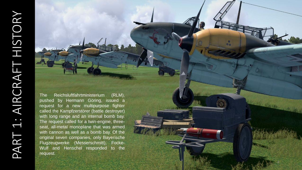
The Reichsluftfahrtministerium (RLM),
pushed by Hermann Göring, issued a
request for a new multipurpose fighter
called the Kampfzerstörer (battle destroyer)
with long range and an internal bomb bay.
The request called for a twin-engine, three-
seat, all-metal monoplane that was armed
with cannon as well as a bomb bay. Of the
original seven companies, only Bayerische
Flugzeugwerke (Messerschmitt), Focke-
Wulf and Henschel responded to the
request.
PAR
T 1
: AIR
CR
AFT
HIS
TOR
Y
5
The basic problem faced by the Bf.110 was that it could not perform its job as a bomber escort against modern fighters. In earlier campaigns that weakness
had been concealed, either by the lack of such opponents in Poland and Norway, or by the speed of the German advance in France, which disrupted the
British and French air effort. It was only over Britain that the Bf 110 came up against a determined enemy equipped with modern fighters, and it simply could
not cope. If a Hurricane or Spitfire was unlucky enough to be caught in front of the guns of a Bf 110, then the British fighter would suffer serious damage, but
that rarely happened. Losses were heavy. During the Battle of Britain, the Luftwaffe lost 223 Bf 110s, having started the battle with only 237. Replacements
could not be found quickly enough to make up these losses. After the Battle of Britain, the Bf 110 could no longer be seen as an elite day fighter.
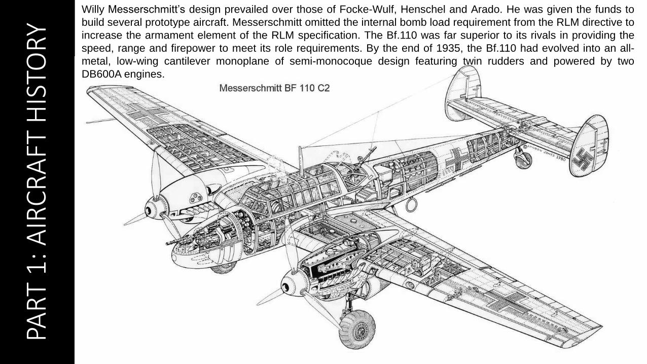
Willy Messerschmitt’s design prevailed over those of Focke-Wulf, Henschel and Arado. He was given the funds to
build several prototype aircraft. Messerschmitt omitted the internal bomb load requirement from the RLM directive to
increase the armament element of the RLM specification. The Bf.110 was far superior to its rivals in providing the
speed, range and firepower to meet its role requirements. By the end of 1935, the Bf.110 had evolved into an all-
metal, low-wing cantilever monoplane of semi-monocoque design featuring twin rudders and powered by two
DB600A engines.

PAR
T 1
: AIR
CR
AFT
HIS
TOR
Y
6
The basic problem faced by the Bf.110 was that it could not perform its job as a bomber
escort against modern fighters. In earlier campaigns that weakness had been concealed,
either by the lack of such opponents in Poland and Norway, or by the speed of the German
advance in France, which disrupted the British and French air effort. It was only over Britain
that the Bf 110 came up against a determined enemy equipped with modern fighters, and it
simply could not cope. If a Hurricane or Spitfire was unlucky enough to be caught in front of
the guns of a Bf 110, then the British fighter would suffer serious damage, but that rarely
happened.
Losses were heavy. During the Battle of Britain, the Luftwaffe lost 223 Bf.110s, having
started the battle with only 237. Replacements could not be found quickly enough to make
up these losses. After the Battle of Britain, the Bf 110 could no longer be seen as an elite
day fighter.
PAR
T 2
: AIR
CR
AFT
VA
RIA
NTS
7
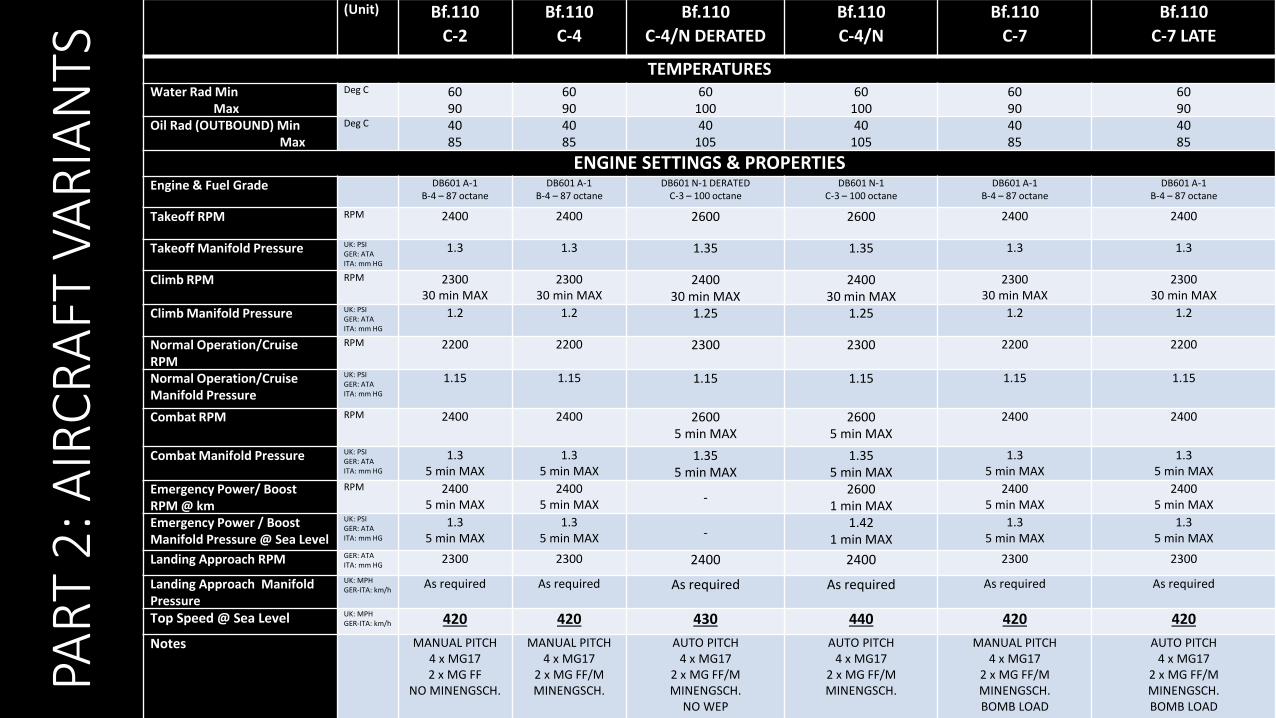
(Unit) Bf.110
C-2
Bf.110
C-4
Bf.110
C-4/N DERATED
Bf.110
C-4/N
Bf.110
C-7
Bf.110
C-7 LATE
TEMPERATURESWater Rad Min
Max
Deg C 6090
6090
60100
60100
6090
6090
Oil Rad (OUTBOUND) MinMax
Deg C 4085
4085
40105
40105
4085
4085
ENGINE SETTINGS & PROPERTIESEngine & Fuel Grade DB601 A-1
B-4 – 87 octaneDB601 A-1
B-4 – 87 octaneDB601 N-1 DERATED
C-3 – 100 octaneDB601 N-1
C-3 – 100 octaneDB601 A-1
B-4 – 87 octaneDB601 A-1
B-4 – 87 octane
Takeoff RPM RPM 2400 2400 2600 2600 2400 2400
Takeoff Manifold Pressure UK: PSIGER: ATAITA: mm HG
1.3 1.3 1.35 1.35 1.3 1.3
Climb RPM RPM 230030 min MAX
230030 min MAX
240030 min MAX
240030 min MAX
230030 min MAX
230030 min MAX
Climb Manifold Pressure UK: PSIGER: ATAITA: mm HG
1.2 1.2 1.25 1.25 1.2 1.2
Normal Operation/CruiseRPM
RPM 2200 2200 2300 2300 2200 2200
Normal Operation/CruiseManifold Pressure
UK: PSIGER: ATAITA: mm HG
1.15 1.15 1.15 1.15 1.15 1.15
Combat RPM RPM 2400 2400 26005 min MAX
26005 min MAX
2400 2400
Combat Manifold Pressure UK: PSIGER: ATAITA: mm HG
1.35 min MAX
1.35 min MAX
1.355 min MAX
1.355 min MAX
1.35 min MAX
1.35 min MAX
Emergency Power/ BoostRPM @ km
RPM 24005 min MAX
24005 min MAX
-2600
1 min MAX2400
5 min MAX2400
5 min MAX
Emergency Power / Boost Manifold Pressure @ Sea Level
UK: PSIGER: ATAITA: mm HG
1.35 min MAX
1.35 min MAX -
1.421 min MAX
1.35 min MAX
1.35 min MAX
Landing Approach RPM GER: ATAITA: mm HG
2300 2300 2400 2400 2300 2300
Landing Approach Manifold Pressure
UK: MPHGER-ITA: km/h
As required As required As required As required As required As required
Top Speed @ Sea Level UK: MPHGER-ITA: km/h 420 420 430 440 420 420
Notes MANUAL PITCH4 x MG172 x MG FF
NO MINENGSCH.
MANUAL PITCH4 x MG17
2 x MG FF/MMINENGSCH.
AUTO PITCH4 x MG17
2 x MG FF/MMINENGSCH.
NO WEP
AUTO PITCH4 x MG17
2 x MG FF/MMINENGSCH.
MANUAL PITCH4 x MG17
2 x MG FF/MMINENGSCH.BOMB LOAD
AUTO PITCH4 x MG17
2 x MG FF/MMINENGSCH.BOMB LOAD
PAR
T 2
: AIR
CR
AFT
VA
RIA
NTS
8
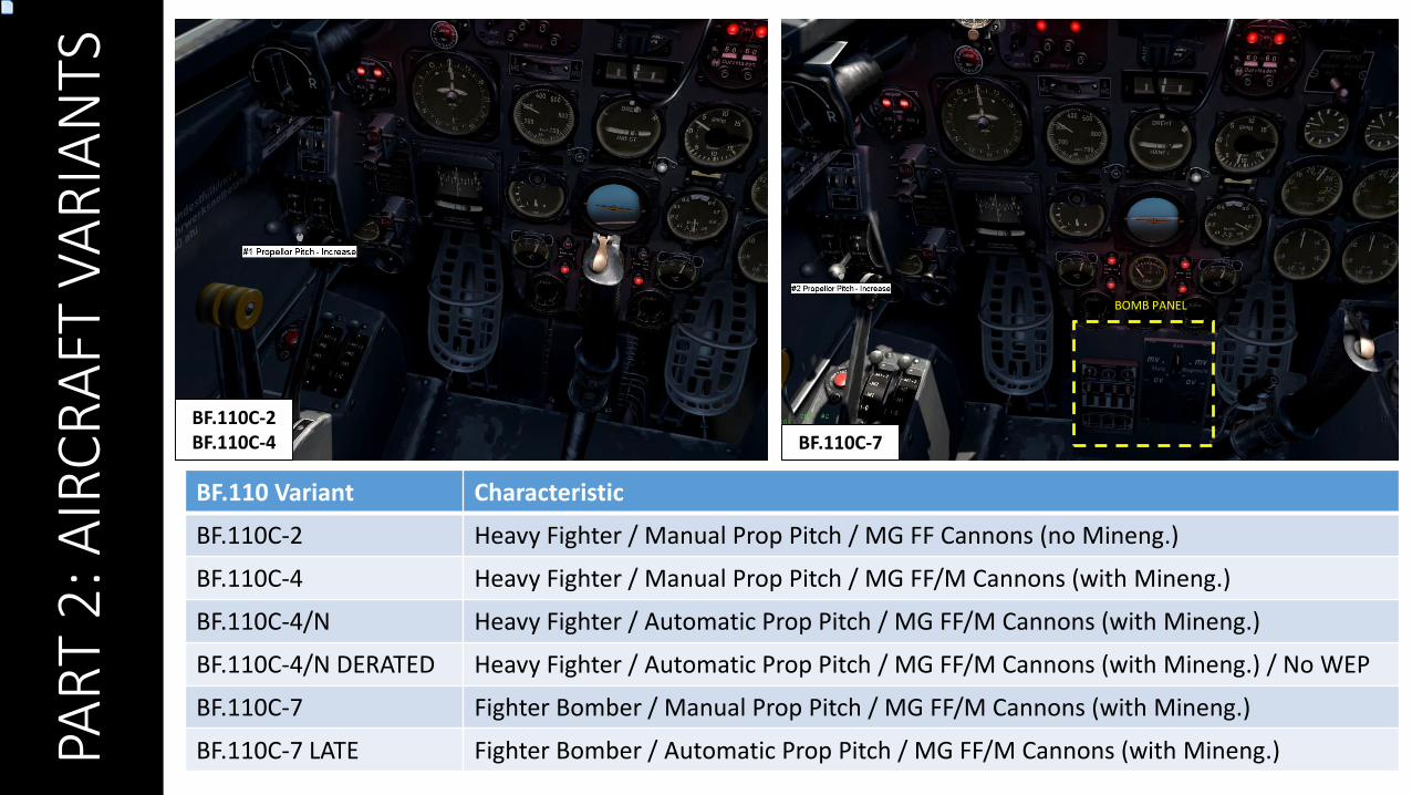
BF.110C-2BF.110C-4 BF.110C-7
BOMB PANEL
BF.110 Variant Characteristic
BF.110C-2 Heavy Fighter / Manual Prop Pitch / MG FF Cannons (no Mineng.)
BF.110C-4 Heavy Fighter / Manual Prop Pitch / MG FF/M Cannons (with Mineng.)
BF.110C-4/N Heavy Fighter / Automatic Prop Pitch / MG FF/M Cannons (with Mineng.)
BF.110C-4/N DERATED Heavy Fighter / Automatic Prop Pitch / MG FF/M Cannons (with Mineng.) / No WEP
BF.110C-7 Fighter Bomber / Manual Prop Pitch / MG FF/M Cannons (with Mineng.)
BF.110C-7 LATE Fighter Bomber / Automatic Prop Pitch / MG FF/M Cannons (with Mineng.)
PAR
T 2
: AIR
CR
AFT
VA
RIA
NTS
9
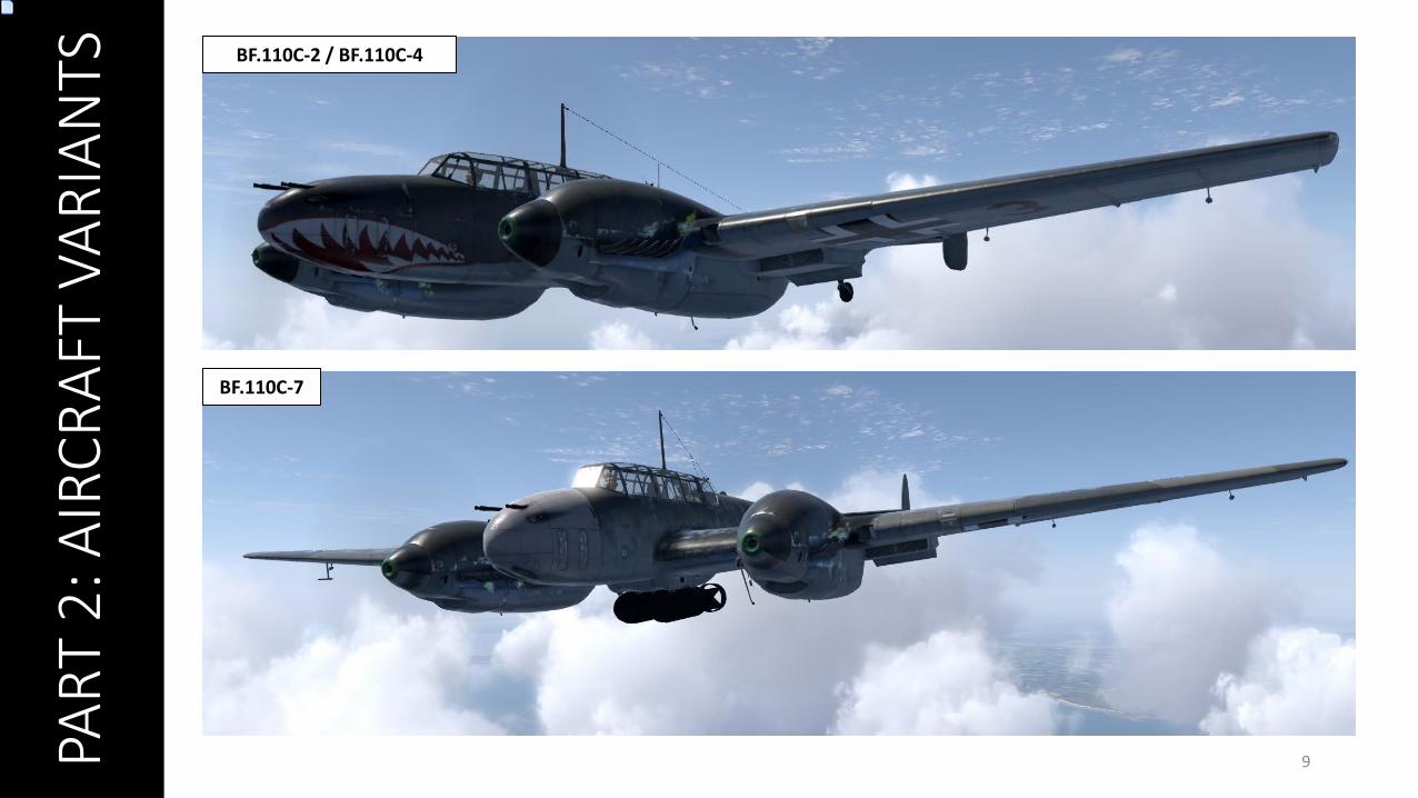
BF.110C-2 / BF.110C-4
BF.110C-7

PAR
T 3
: AIR
CR
AFT
& C
OC
KP
IT
FAM
ILIA
RIZ
ATIO
N
10
CREW MEMBERS
PILOT
DORSAL GUNNER
PAR
T 3
: AIR
CR
AFT
& C
OC
KP
IT
FAM
ILIA
RIZ
ATIO
N
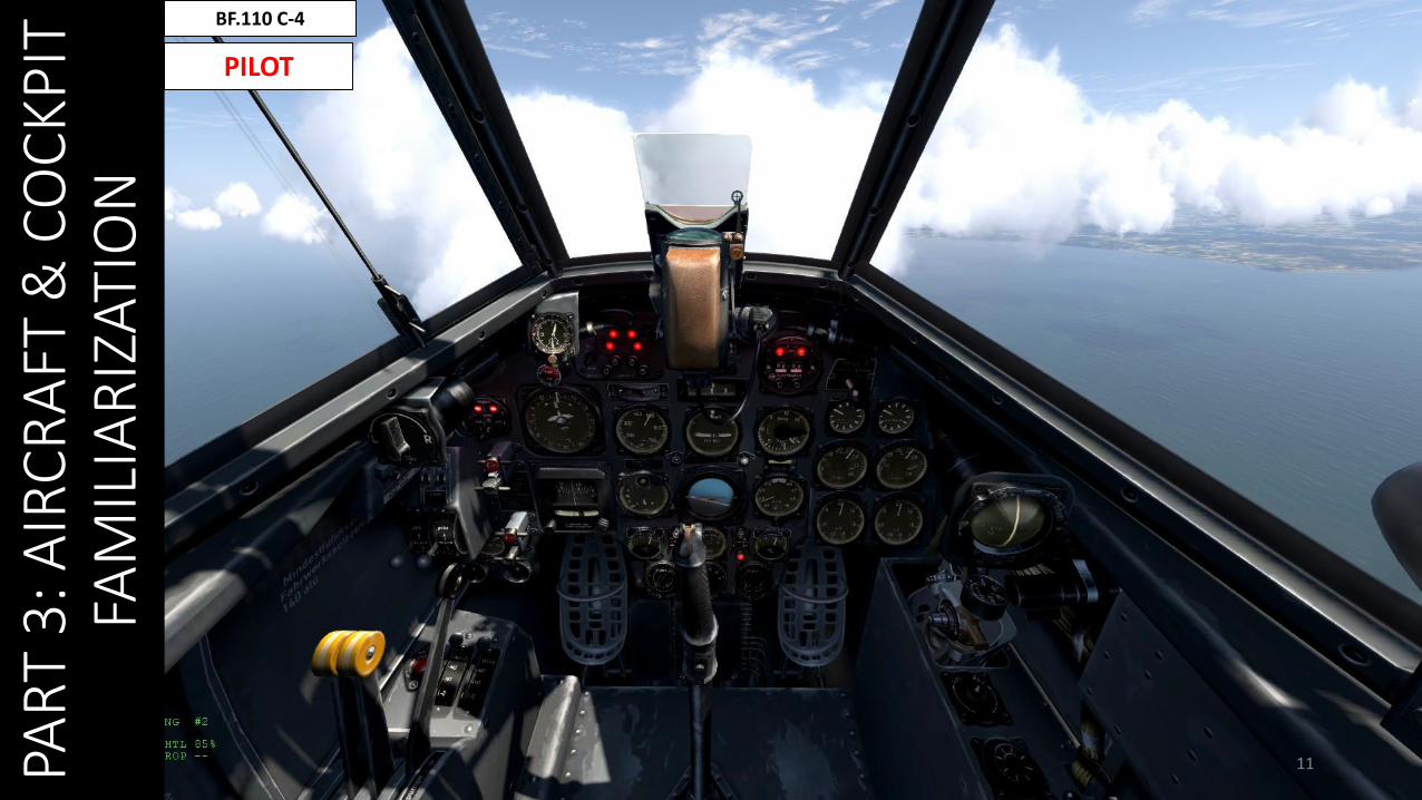
11
BF.110 C-4
PILOT

PAR
T 3
: AIR
CR
AFT
& C
OC
KP
IT
FAM
ILIA
RIZ
ATIO
N
12
BF.110 C-4
PILOT
FUEL TRANSFER SYSTEM (SEE “ENGINE MANAGEMENT SECTION FOR FUEL SYSTEM MANAGEMENT)
PAR
T 3
: AIR
CR
AFT
& C
OC
KP
IT
FAM
ILIA
RIZ
ATIO
N
13
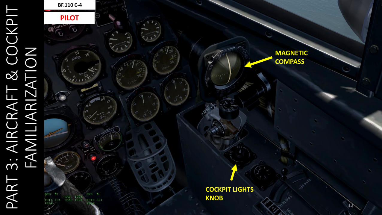
BF.110 C-4
PILOT
COCKPIT LIGHTS KNOB
MAGNETIC COMPASS
PAR
T 3
: AIR
CR
AFT
& C
OC
KP
IT
FAM
ILIA
RIZ
ATIO
N
14
BF.110 C-4
PILOT
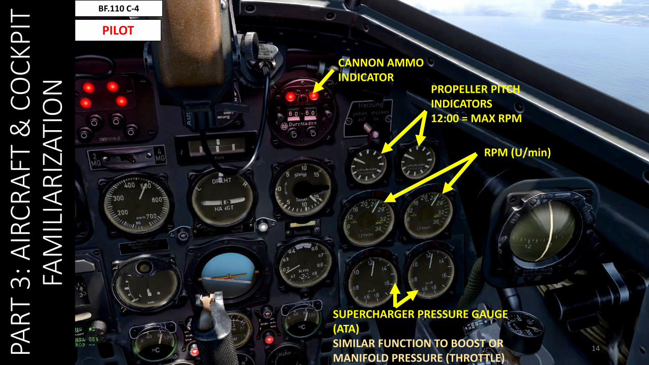
PROPELLER PITCH INDICATORS12:00 = MAX RPM
RPM (U/min)
SUPERCHARGER PRESSURE GAUGE (ATA)SIMILAR FUNCTION TO BOOST OR MANIFOLD PRESSURE (THROTTLE)
CANNON AMMOINDICATOR
PAR
T 3
: AIR
CR
AFT
& C
OC
KP
IT
FAM
ILIA
RIZ
ATIO
N
15
BF.110 C-4
PILOT
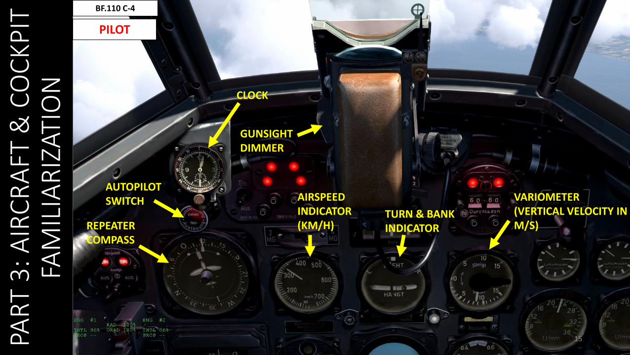
CLOCK
GUNSIGHT DIMMER
AIRSPEED INDICATOR (KM/H)
TURN & BANKINDICATOR
VARIOMETER (VERTICAL VELOCITY IN M/S)REPEATER
COMPASS
AUTOPILOTSWITCH
PAR
T 3
: AIR
CR
AFT
& C
OC
KP
IT
FAM
ILIA
RIZ
ATIO
N
16
BF.110 C-4
PILOT
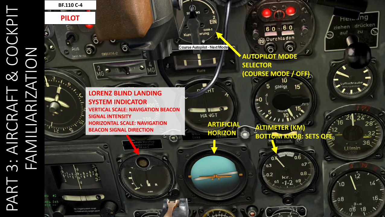
LORENZ BLIND LANDING SYSTEM INDICATORVERTICAL SCALE: NAVIGATION BEACON SIGNAL INTENSITYHORIZONTAL SCALE: NAVIGATION BEACON SIGNAL DIRECTION
ARTIFICIAL HORIZON
ALTIMETER (KM)BOTTOM KNOB: SETS QFE
AUTOPILOT MODE SELECTOR(COURSE MODE / OFF)
PAR
T 3
: AIR
CR
AFT
& C
OC
KP
IT
FAM
ILIA
RIZ
ATIO
N
17
BF.110 C-4
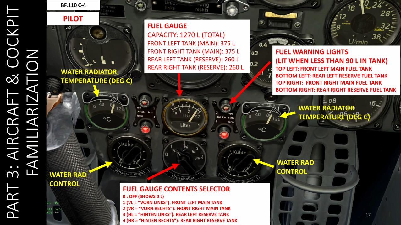
PILOTFUEL GAUGECAPACITY: 1270 L (TOTAL)FRONT LEFT TANK (MAIN): 375 LFRONT RIGHT TANK (MAIN): 375 LREAR LEFT TANK (RESERVE): 260 LREAR RIGHT TANK (RESERVE): 260 L
WATER RADIATORTEMPERATURE (DEG C)
WATER RADIATORTEMPERATURE (DEG C)
FUEL WARNING LIGHTS(LIT WHEN LESS THAN 90 L IN TANK)TOP LEFT: FRONT LEFT MAIN FUEL TANKBOTTOM LEFT: REAR LEFT RESERVE FUEL TANKTOP RIGHT: FRONT RIGHT MAIN FUEL TANKBOTTOM RIGHT: REAR RIGHT RESERVE FUEL TANK
WATER RADCONTROL
WATER RADCONTROL
FUEL GAUGE CONTENTS SELECTOR0 : OFF (SHOWS 0 L)1 (VL = “VORN LINKS”): FRONT LEFT MAIN TANK2 (VR = “VORN RECHTS”): FRONT RIGHT MAIN TANK3 (HL = “HINTEN LINKS”): REAR LEFT RESERVE TANK4 (HR = “HINTEN RECHTS”): REAR RIGHT RESERVE TANK
PAR
T 3
: AIR
CR
AFT
& C
OC
KP
IT
FAM
ILIA
RIZ
ATIO
N
18
BF.110 C-4
PILOT
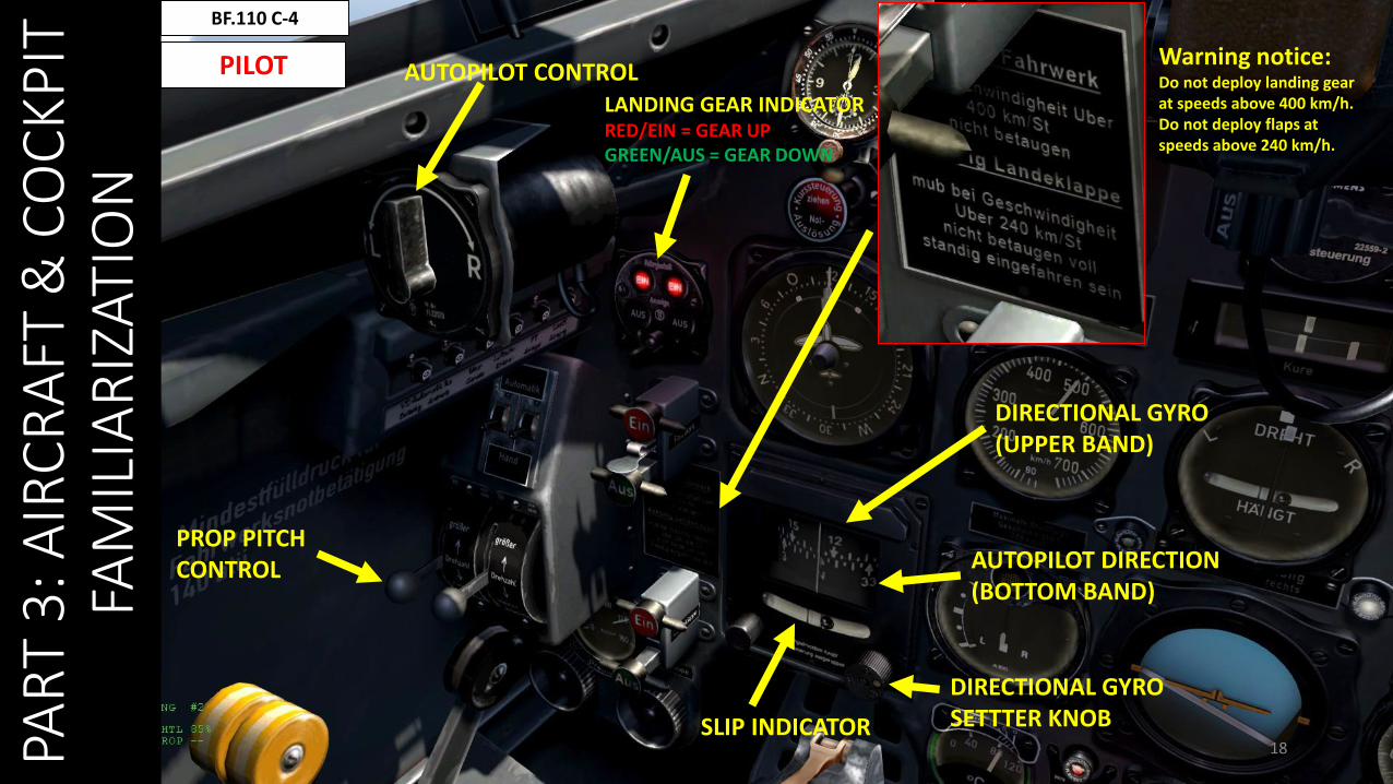
DIRECTIONAL GYRO (UPPER BAND)
DIRECTIONAL GYRO SETTTER KNOBSLIP INDICATOR
AUTOPILOT DIRECTION (BOTTOM BAND)
AUTOPILOT CONTROLWarning notice:Do not deploy landing gear at speeds above 400 km/h.Do not deploy flaps at speeds above 240 km/h.
LANDING GEAR INDICATORRED/EIN = GEAR UPGREEN/AUS = GEAR DOWN
PROP PITCHCONTROL
PAR
T 3
: AIR
CR
AFT
& C
OC
KP
IT
FAM
ILIA
RIZ
ATIO
N
19
BF.110 C-4
PILOT
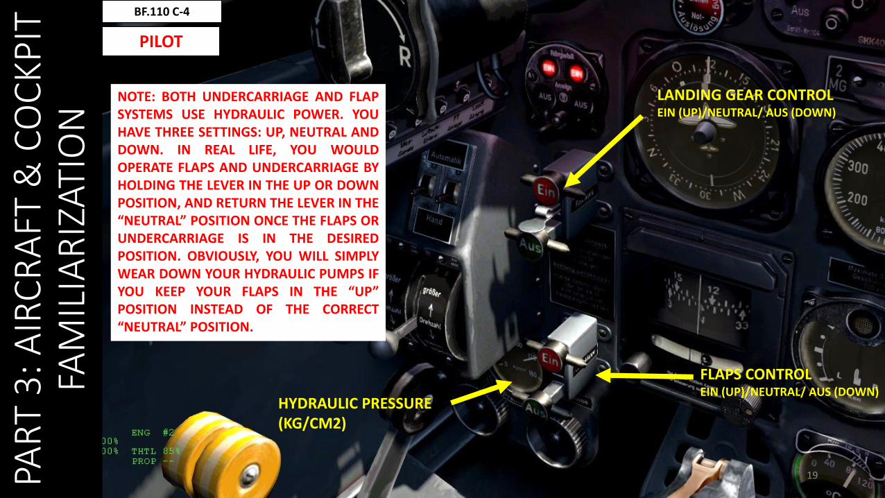
LANDING GEAR CONTROLEIN (UP)/NEUTRAL/ AUS (DOWN)
FLAPS CONTROLEIN (UP)/NEUTRAL/ AUS (DOWN)
HYDRAULIC PRESSURE(KG/CM2)
NOTE: BOTH UNDERCARRIAGE AND FLAPSYSTEMS USE HYDRAULIC POWER. YOUHAVE THREE SETTINGS: UP, NEUTRAL ANDDOWN. IN REAL LIFE, YOU WOULDOPERATE FLAPS AND UNDERCARRIAGE BYHOLDING THE LEVER IN THE UP OR DOWNPOSITION, AND RETURN THE LEVER IN THE“NEUTRAL” POSITION ONCE THE FLAPS ORUNDERCARRIAGE IS IN THE DESIREDPOSITION. OBVIOUSLY, YOU WILL SIMPLYWEAR DOWN YOUR HYDRAULIC PUMPS IFYOU KEEP YOUR FLAPS IN THE “UP”POSITION INSTEAD OF THE CORRECT“NEUTRAL” POSITION.
PAR
T 3
: AIR
CR
AFT
& C
OC
KP
IT
FAM
ILIA
RIZ
ATIO
N
20
BF.110 C-4
PILOT
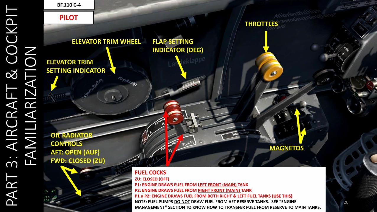
FLAP SETTING INDICATOR (DEG)
ELEVATOR TRIM WHEEL
ELEVATOR TRIM SETTING INDICATOR
FUEL COCKSZU: CLOSED (OFF)P1: ENGINE DRAWS FUEL FROM LEFT FRONT (MAIN) TANKP2: ENGINE DRAWS FUEL FROM RIGHT FRONT (MAIN) TANKP1 u P2: ENGINE DRAWS FUEL FROM BOTH RIGHT & LEFT FUEL TANKS (USE THIS)NOTE: FUEL PUMPS DO NOT DRAW FUEL FROM AFT RESERVE TANKS. SEE “ENGINE MANAGEMENT” SECTION TO KNOW HOW TO TRANSFER FUEL FROM RESERVE TO MAIN TANKS.
THROTTLES
MAGNETOS
OIL RADIATOR CONTROLSAFT: OPEN (AUF)FWD: CLOSED (ZU)

PAR
T 3
: AIR
CR
AFT
& C
OC
KP
IT
FAM
ILIA
RIZ
ATIO
N
21
BF.110 C-4
PILOT
OIL TEMPERATURE(DEG C)
LEFT: FUEL PRESSURE(KG/CM2)RIGHT: OIL PRESSURE(KG/CM2)
22PAR
T 3
: AIR
CR
AFT
& C
OC
KP
IT
FAM
ILIA
RIZ
ATIO
N
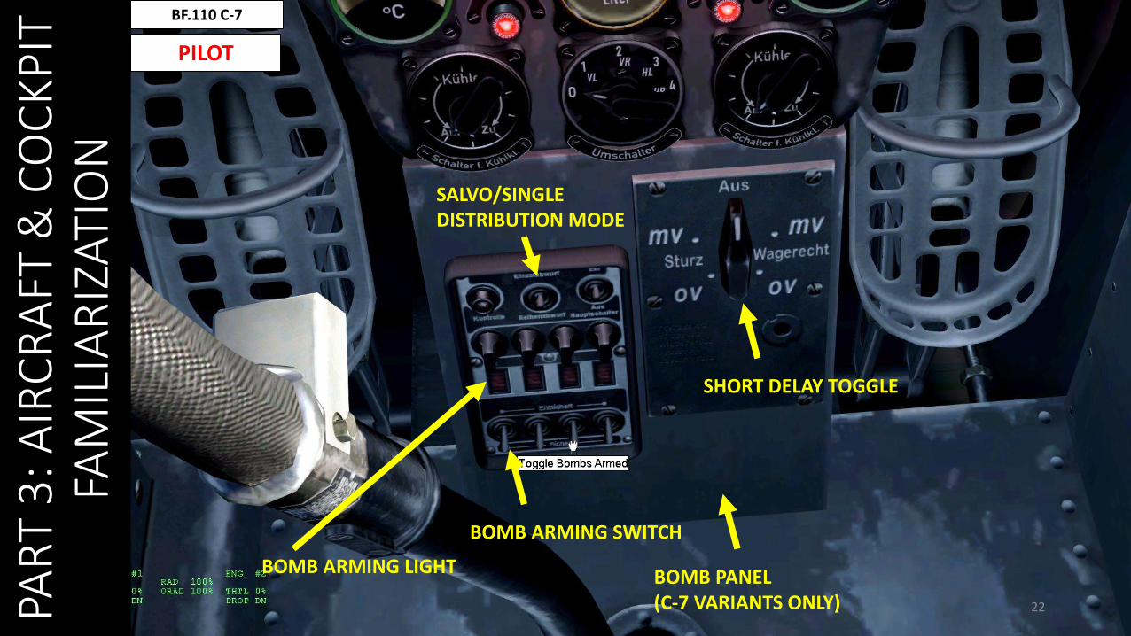
BF.110 C-7
PILOT
BOMB PANEL (C-7 VARIANTS ONLY)
BOMB ARMING SWITCH
SHORT DELAY TOGGLE
SALVO/SINGLE DISTRIBUTION MODE
BOMB ARMING LIGHT
PAR
T 3
: AIR
CR
AFT
& C
OC
KP
IT
FAM
ILIA
RIZ
ATIO
N
23
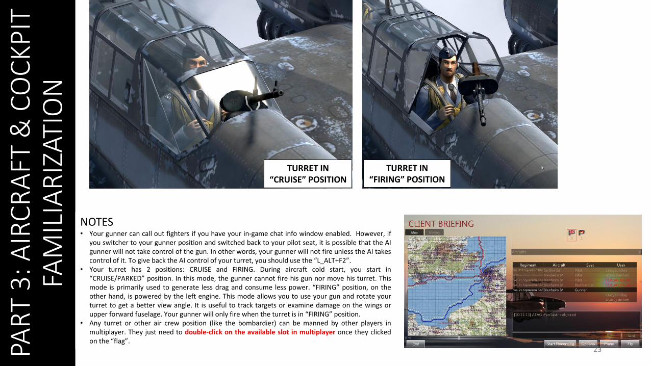
NOTES• Your gunner can call out fighters if you have your in-game chat info window enabled. However, if
you switcher to your gunner position and switched back to your pilot seat, it is possible that the AIgunner will not take control of the gun. In other words, your gunner will not fire unless the AI takescontrol of it. To give back the AI control of your turret, you should use the “L_ALT+F2”.
• Your turret has 2 positions: CRUISE and FIRING. During aircraft cold start, you start in“CRUISE/PARKED” position. In this mode, the gunner cannot fire his gun nor move his turret. Thismode is primarily used to generate less drag and consume less power. “FIRING” position, on theother hand, is powered by the left engine. This mode allows you to use your gun and rotate yourturret to get a better view angle. It is useful to track targets or examine damage on the wings orupper forward fuselage. Your gunner will only fire when the turret is in “FIRING” position.
• Any turret or other air crew position (like the bombardier) can be manned by other players inmultiplayer. They just need to double-click on the available slot in multiplayer once they clickedon the “flag”.
TURRET IN “CRUISE” POSITION
TURRET IN “FIRING” POSITION
PAR
T 3
: AIR
CR
AFT
& C
OC
KP
IT
FAM
ILIA
RIZ
ATIO
N
24
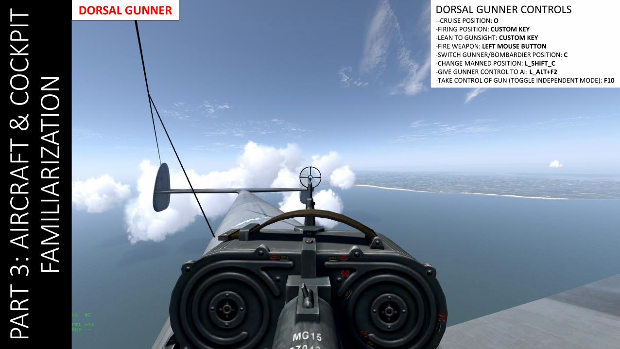
DORSAL GUNNER DORSAL GUNNER CONTROLS--CRUISE POSITION: O-FIRING POSITION: CUSTOM KEY-LEAN TO GUNSIGHT: CUSTOM KEY-FIRE WEAPON: LEFT MOUSE BUTTON-SWITCH GUNNER/BOMBARDIER POSITION: C-CHANGE MANNED POSITION: L_SHIFT_C-GIVE GUNNER CONTROL TO AI: L_ALT+F2-TAKE CONTROL OF GUN (TOGGLE INDEPENDENT MODE): F10

PAR
T 3
: AIR
CR
AFT
& C
OC
KP
IT
FAM
ILIA
RIZ
ATIO
N
25
OIL RAD OPENGOOD = MORE AIRFLOW TO COOL THE ENGINEBAD = MORE DRAG, LESS SPEED
WATER RAD CLOSEDGOOD = LESS DRAG, MORE SPEEDBAD = LESS AIRFLOW TO COOL THE ENGINE, HIGH RISK OF ENGINE OVERHEAT
WATER RAD OPENGOOD = MORE AIRFLOW TO COOLTHE ENGINEBAD = MORE DRAG, LESS SPEED OIL RAD CLOSED
GOOD = LESS DRAG, MORE SPEEDBAD = LESS AIRFLOW TO COOL THE ENGINE, HIGH RISK OF ENGINE OVERHEAT
CHECK THE “ENGINE MANAGEMENT” SECTION FOR RECOMMENDED RADIATOR SETTINGS.

CRITICAL COMPONENTSPA
RT
3: A
IRC
RA
FT &
CO
CK
PIT
FA
MIL
IAR
IZAT
ION
26
WING SPAR
FUEL TANKS
CONTROL CABLES
WATER RADIATOR
OIL RADIATOR
7.92 mmMACHINEGUN(4 TOTAL)
20 mm CANNON(2 TOTAL)
PAR
T 3
: AIR
CR
AFT
& C
OC
KP
IT
FAM
ILIA
RIZ
ATIO
N
27
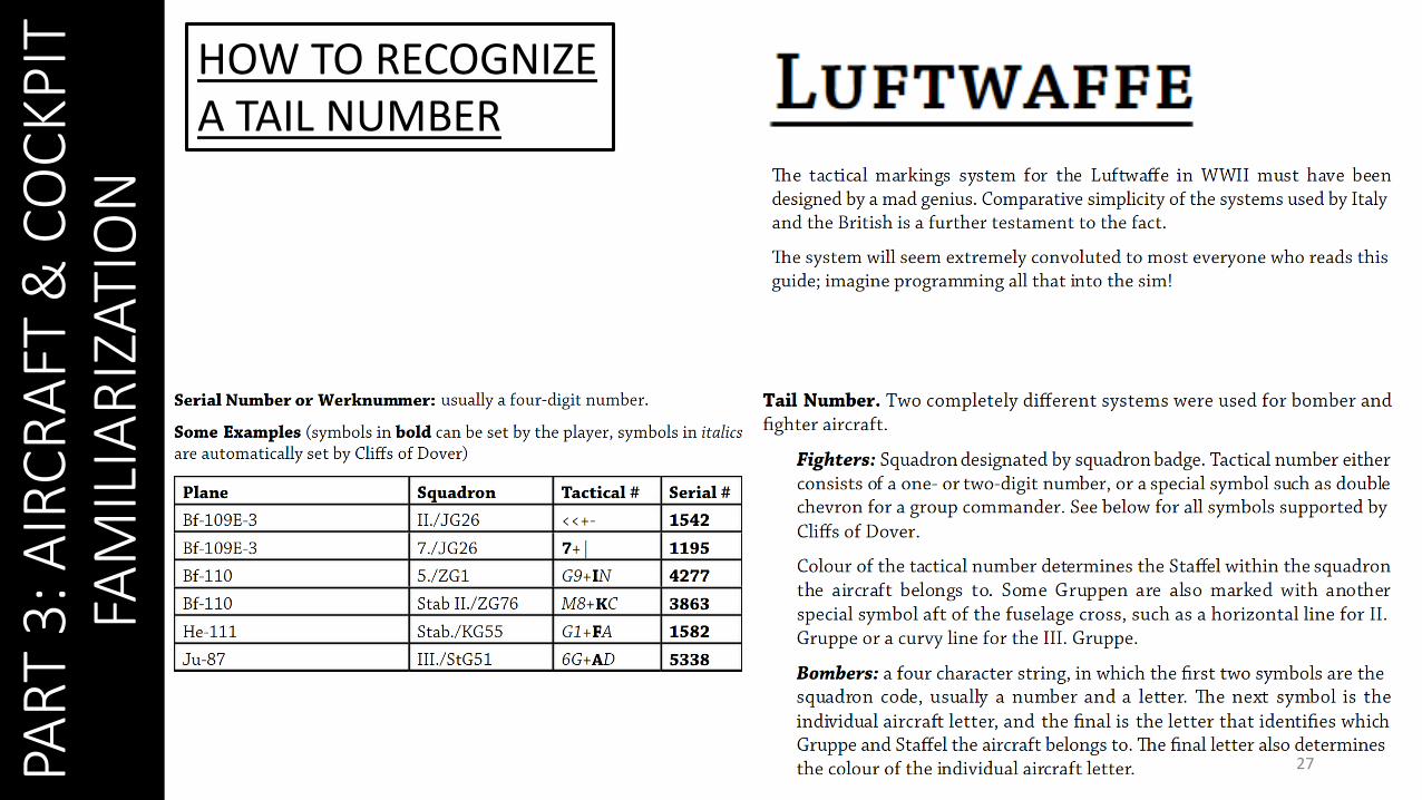
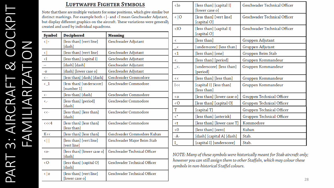
HOW TO RECOGNIZEA TAIL NUMBER
PAR
T 3
: AIR
CR
AFT
& C
OC
KP
IT
FAM
ILIA
RIZ
ATIO
N
28
PAR
T 4
: CO
NTR
OLS
29
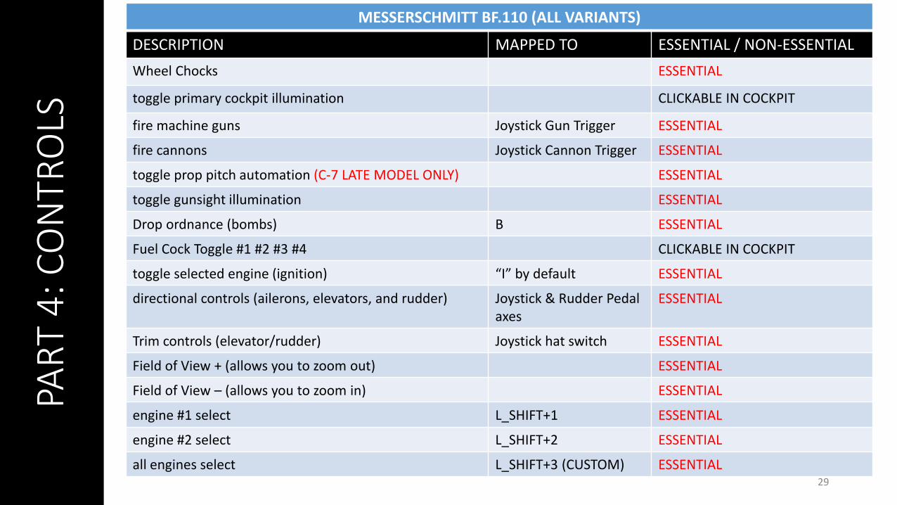
MESSERSCHMITT BF.110 (ALL VARIANTS)
DESCRIPTION MAPPED TO ESSENTIAL / NON-ESSENTIAL
Wheel Chocks ESSENTIAL
toggle primary cockpit illumination CLICKABLE IN COCKPIT
fire machine guns Joystick Gun Trigger ESSENTIAL
fire cannons Joystick Cannon Trigger ESSENTIAL
toggle prop pitch automation (C-7 LATE MODEL ONLY) ESSENTIAL
toggle gunsight illumination ESSENTIAL
Drop ordnance (bombs) B ESSENTIAL
Fuel Cock Toggle #1 #2 #3 #4 CLICKABLE IN COCKPIT
toggle selected engine (ignition) “I” by default ESSENTIAL
directional controls (ailerons, elevators, and rudder) Joystick & Rudder Pedal axes
ESSENTIAL
Trim controls (elevator/rudder) Joystick hat switch ESSENTIAL
Field of View + (allows you to zoom out) ESSENTIAL
Field of View – (allows you to zoom in) ESSENTIAL
engine #1 select L_SHIFT+1 ESSENTIAL
engine #2 select L_SHIFT+2 ESSENTIAL
all engines select L_SHIFT+3 (CUSTOM) ESSENTIAL

PAR
T 4
: CO
NTR
OLS
30
MESSERSCHMITT BF.110 (ALL VARIANTS)
DESCRIPTION MAPPED TO ESSENTIAL / NON-ESSENTIAL
lean to gunsight NOT ESSENTIAL
throttle Throttle axis ESSENTIAL
War Emergency Power ESSENTIAL
toggle canopy/hatch ESSENTIAL
Jettison canopy ESSENTIAL
Open oil radiator Right Arrow keyboard ESSENTIAL
close oil radiator Left Arrow keyboard ESSENTIAL
open radiator Up Arrow keyboard ESSENTIAL
close radiator Down Arrow keyboard ESSENTIAL
increase propeller pitch CUSTOM. DO NOT MAP TO AXIS LIKE FOR THE RAF A/C. MAP TO KEYS INSTEAD.
ESSENTIAL
decrease propeller pitch ESSENTIAL
Toggle undercarriage (landing gear) ESSENTIAL
Left / Right Wheel brake Map in AXES if pedals ESSENTIAL
bail out ESSENTIAL
Toggle Independent Mode (allows you to use/hide mouse cursor)
F10 ESSENTIAL
PAR
T 4
: CO
NTR
OLS
31
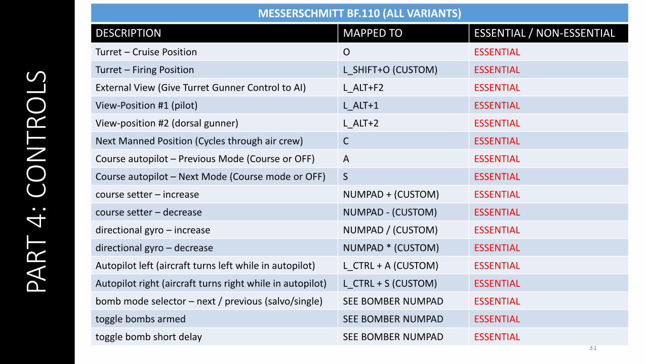
MESSERSCHMITT BF.110 (ALL VARIANTS)
DESCRIPTION MAPPED TO ESSENTIAL / NON-ESSENTIAL
Turret – Cruise Position O ESSENTIAL
Turret – Firing Position L_SHIFT+O (CUSTOM) ESSENTIAL
External View (Give Turret Gunner Control to AI) L_ALT+F2 ESSENTIAL
View-Position #1 (pilot) L_ALT+1 ESSENTIAL
View-position #2 (dorsal gunner) L_ALT+2 ESSENTIAL
Next Manned Position (Cycles through air crew) C ESSENTIAL
Course autopilot – Previous Mode (Course or OFF) A ESSENTIAL
Course autopilot – Next Mode (Course mode or OFF) S ESSENTIAL
course setter – increase NUMPAD + (CUSTOM) ESSENTIAL
course setter – decrease NUMPAD - (CUSTOM) ESSENTIAL
directional gyro – increase NUMPAD / (CUSTOM) ESSENTIAL
directional gyro – decrease NUMPAD * (CUSTOM) ESSENTIAL
Autopilot left (aircraft turns left while in autopilot) L_CTRL + A (CUSTOM) ESSENTIAL
Autopilot right (aircraft turns right while in autopilot) L_CTRL + S (CUSTOM) ESSENTIAL
bomb mode selector – next / previous (salvo/single) SEE BOMBER NUMPAD ESSENTIAL
toggle bombs armed SEE BOMBER NUMPAD ESSENTIAL
toggle bomb short delay SEE BOMBER NUMPAD ESSENTIAL

32
• Most german aircraft, unlike the majority of British and Russian planes, has a “toe brake” or“heel brake” system, which is linked to each individual wheel of your landing gear.
• In order to brake, you need to hold either your left or right wheel toe brake key to steer youraircraft. Applying rudder will also help you turn tighter.
• The main landing wheel brake system employs hydraulically actuated disc-type brakes. Eachbrake is operated by individual master brake cylinders located directly forward of the instrumentpanel. The brakes are selectively controlled by means of toe pedals incorporated into the rudderpedal assembly.
• Be careful: your “wheel brake” command used for Differential braking aircraft will lock both yourbrakes in a german plane. You can map “left/right wheel brake” axes if you have rudder pedals.
PAR
T 4
: CO
NTR
OLS
PAR
T 5
: WEA
PO
NS
AN
D
AR
MA
MEN
T
33
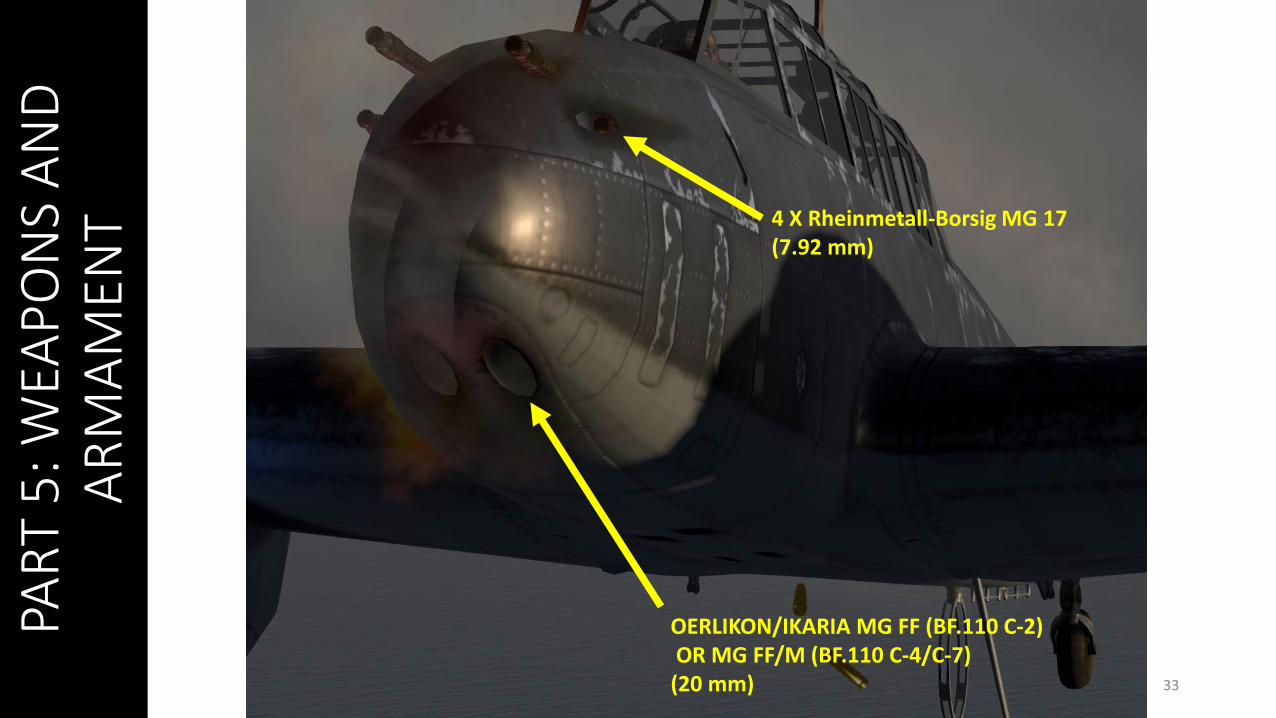
4 X Rheinmetall-Borsig MG 17(7.92 mm)
OERLIKON/IKARIA MG FF (BF.110 C-2)OR MG FF/M (BF.110 C-4/C-7)
(20 mm)
PAR
T 5
: WEA
PO
NS
AN
D
AR
MA
MEN
T
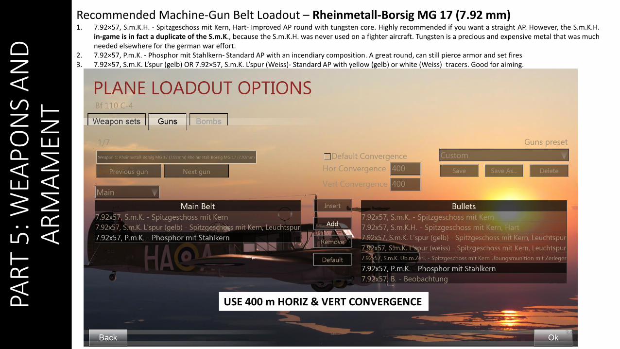
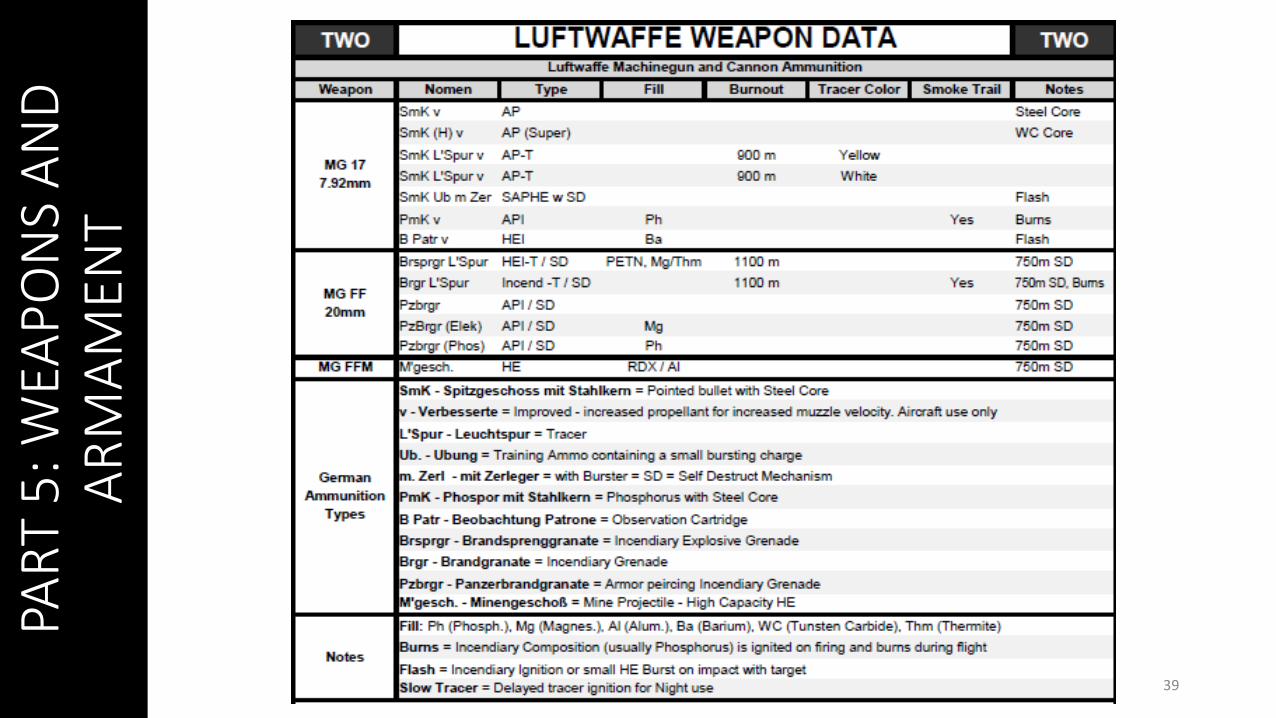
Recommended Machine-Gun Belt Loadout – Rheinmetall-Borsig MG 17 (7.92 mm)1. 7.92×57, S.m.K.H. - Spitzgeschoss mit Kern, Hart- Improved AP round with tungsten core. Highly recommended if you want a straight AP. However, the S.m.K.H.
in-game is in fact a duplicate of the S.m.K., because the S.m.K.H. was never used on a fighter aircraft. Tungsten is a precious and expensive metal that was muchneeded elsewhere for the german war effort.
2. 7.92×57, P.m.K. - Phosphor mit Stahlkern- Standard AP with an incendiary composition. A great round, can still pierce armor and set fires3. 7.92×57, S.m.K. L’spur (gelb) OR 7.92×57, S.m.K. L’spur (Weiss)- Standard AP with yellow (gelb) or white (Weiss) tracers. Good for aiming.
34
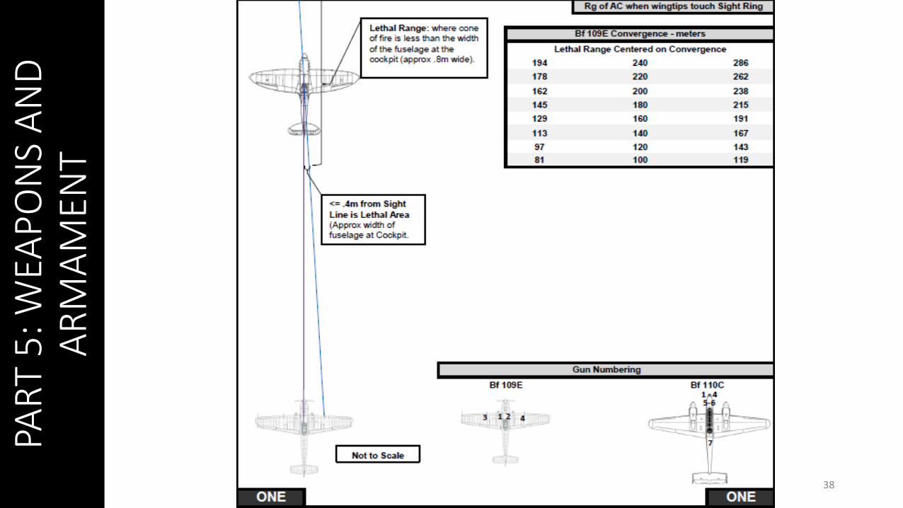
USE 400 m HORIZ & VERT CONVERGENCE
PAR
T 5
: WEA
PO
NS
AN
D
AR
MA
MEN
T
35
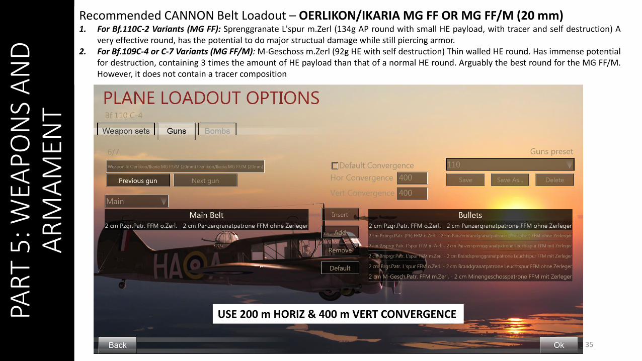
Recommended CANNON Belt Loadout – OERLIKON/IKARIA MG FF OR MG FF/M (20 mm)1. For Bf.110C-2 Variants (MG FF): Sprenggranate L'spur m.Zerl (134g AP round with small HE payload, with tracer and self destruction) A
very effective round, has the potential to do major structual damage while still piercing armor.2. For Bf.109C-4 or C-7 Variants (MG FF/M): M-Geschoss m.Zerl (92g HE with self destruction) Thin walled HE round. Has immense potential
for destruction, containing 3 times the amount of HE payload than that of a normal HE round. Arguably the best round for the MG FF/M.However, it does not contain a tracer composition
USE 200 m HORIZ & 400 m VERT CONVERGENCE
PAR
T 5
: WEA
PO
NS
AN
D
AR
MA
MEN
T
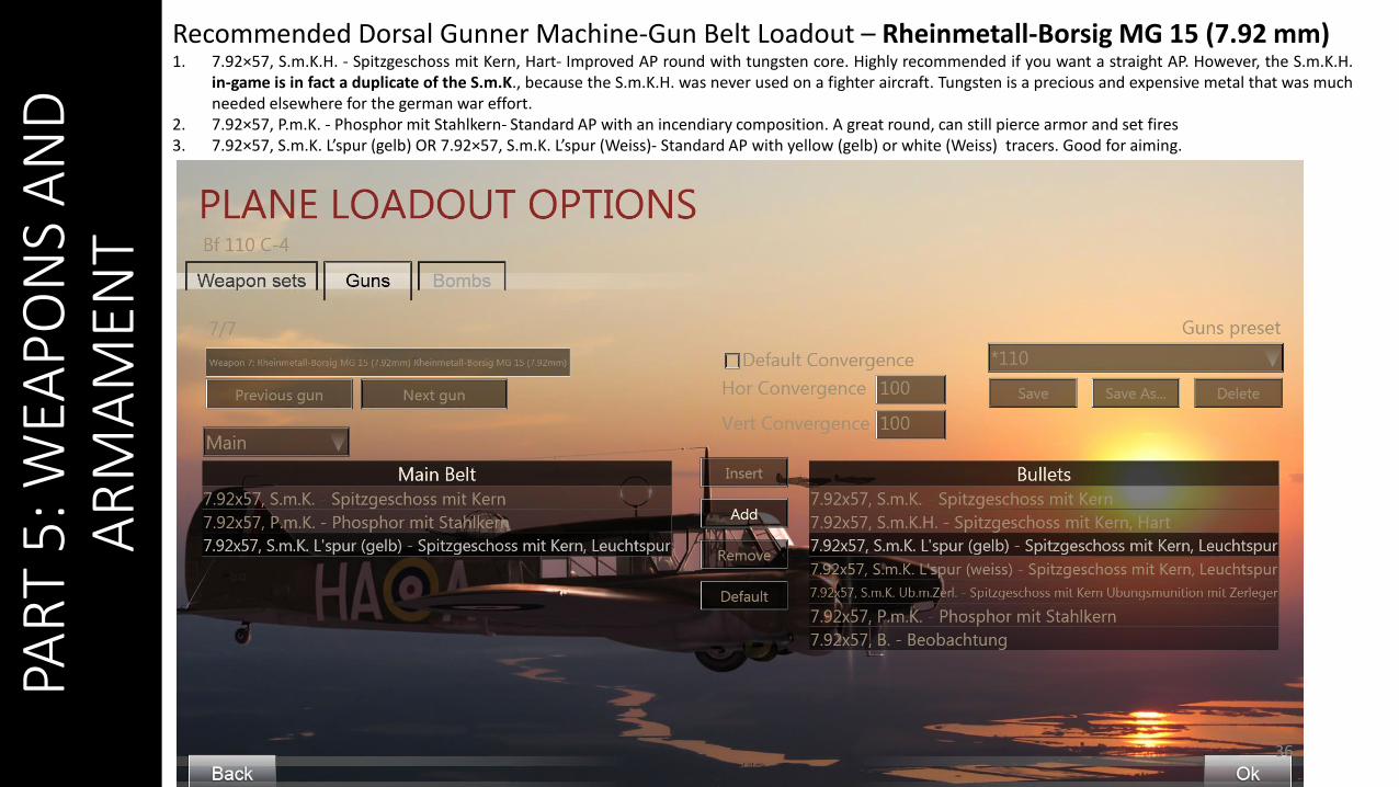
Recommended Dorsal Gunner Machine-Gun Belt Loadout – Rheinmetall-Borsig MG 15 (7.92 mm)1. 7.92×57, S.m.K.H. - Spitzgeschoss mit Kern, Hart- Improved AP round with tungsten core. Highly recommended if you want a straight AP. However, the S.m.K.H.
in-game is in fact a duplicate of the S.m.K., because the S.m.K.H. was never used on a fighter aircraft. Tungsten is a precious and expensive metal that was muchneeded elsewhere for the german war effort.
2. 7.92×57, P.m.K. - Phosphor mit Stahlkern- Standard AP with an incendiary composition. A great round, can still pierce armor and set fires3. 7.92×57, S.m.K. L’spur (gelb) OR 7.92×57, S.m.K. L’spur (Weiss)- Standard AP with yellow (gelb) or white (Weiss) tracers. Good for aiming.
36
PAR
T 5
: WEA
PO
NS
AN
D
AR
MA
MEN
T
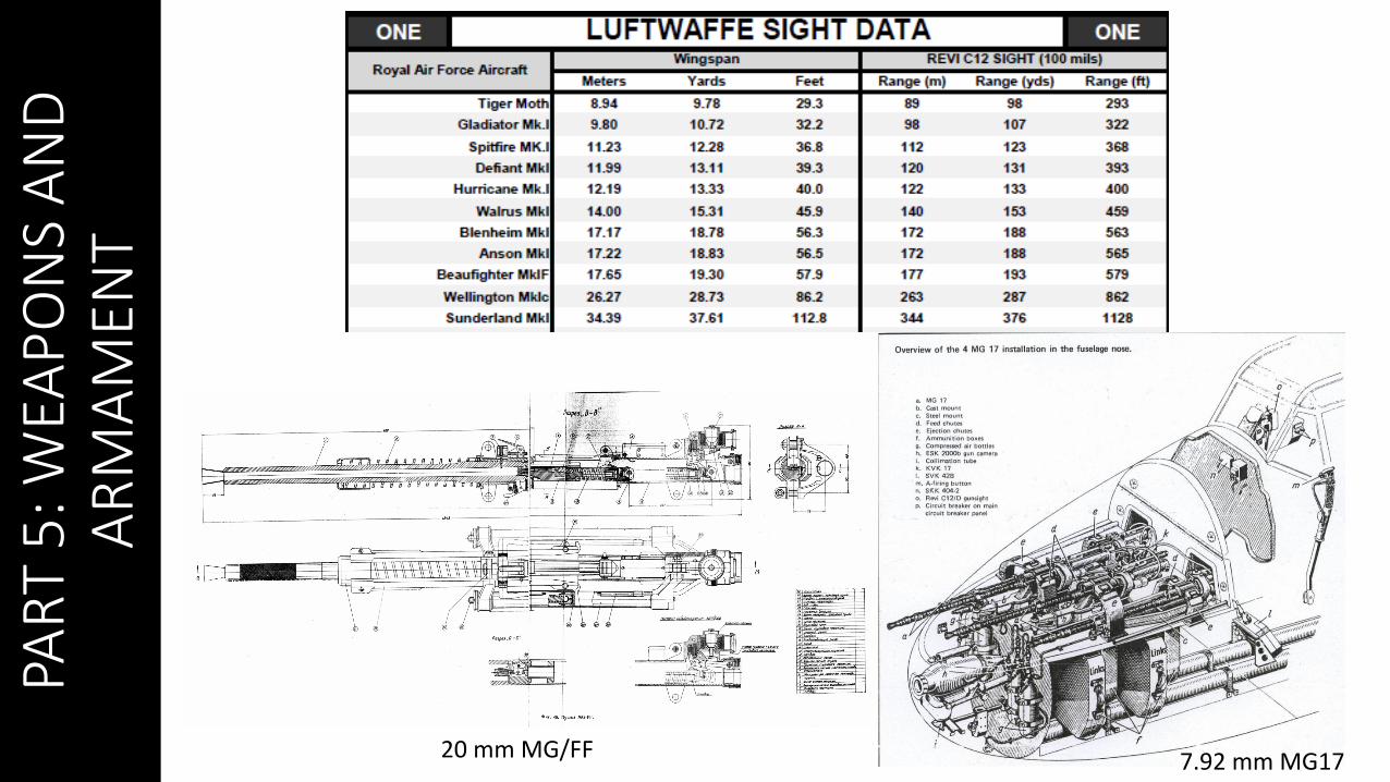
3720 mm MG/FF 7.92 mm MG17
PAR
T 5
: WEA
PO
NS
AN
D
AR
MA
MEN
T
38
PAR
T 5
: WEA
PO
NS
AN
D
AR
MA
MEN
T
39
PAR
T 5
: WEA
PO
NS
AN
D
AR
MA
MEN
T
40
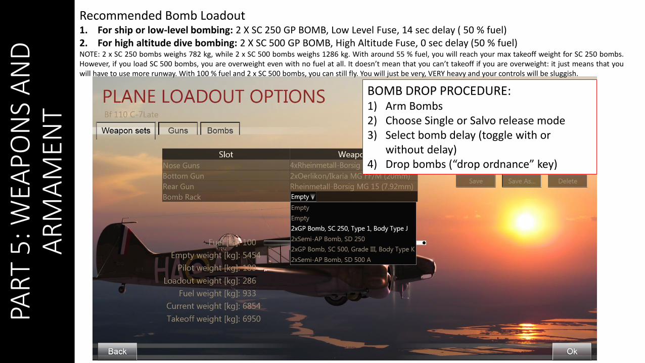
Recommended Bomb Loadout1. For ship or low-level bombing: 2 X SC 250 GP BOMB, Low Level Fuse, 14 sec delay ( 50 % fuel)2. For high altitude dive bombing: 2 X SC 500 GP BOMB, High Altitude Fuse, 0 sec delay (50 % fuel)NOTE: 2 x SC 250 bombs weighs 782 kg, while 2 x SC 500 bombs weighs 1286 kg. With around 55 % fuel, you will reach your max takeoff weight for SC 250 bombs.However, if you load SC 500 bombs, you are overweight even with no fuel at all. It doesn’t mean that you can’t takeoff if you are overweight: it just means that youwill have to use more runway. With 100 % fuel and 2 x SC 500 bombs, you can still fly. You will just be very, VERY heavy and your controls will be sluggish.
BOMB DROP PROCEDURE:1) Arm Bombs2) Choose Single or Salvo release mode3) Select bomb delay (toggle with or
without delay)4) Drop bombs (“drop ordnance” key)
PAR
T 5
: WEA
PO
NS
AN
D
AR
MA
MEN
T
41

PAR
T 5
: WEA
PO
NS
AN
D
AR
MA
MEN
T
42
BOMB DROP PROCEDURE:1) Arm Bombs2) Choose Single or Salvo
bomb release mode3) Select bomb delay (toggle
with or without delay)4) Drop bombs (“drop
ordnance” key)1
2
3
PAR
T 6
: TA
KEO
FF
43
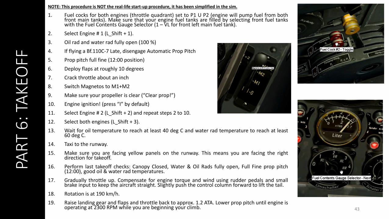
NOTE: This procedure is NOT the real-life start-up procedure, it has been simplified in the sim.
1. Fuel cocks for both engines (throttle quadrant) set to P1 U P2 (engine will pump fuel from bothfront main tanks). Make sure that your engine fuel tanks are filled by selecting front fuel tankswith the Fuel Contents Gauge Selector (1 – VL for front left main fuel tank).
2. Select Engine # 1 (L_Shift + 1).
3. Oil rad and water rad fully open (100 %)
4. If flying a Bf.110C-7 Late, disengage Automatic Prop Pitch
5. Prop pitch full fine (12:00 position)
6. Deploy flaps at roughly 10 degrees
7. Crack throttle about an inch
8. Switch Magnetos to M1+M2
9. Make sure your propeller is clear (“Clear prop!”)
10. Engine ignition! (press “I” by default)
11. Select Engine # 2 (L_Shift + 2) and repeat steps 2 to 10.
12. Select both engines (L_Shift + 3).
13. Wait for oil temperature to reach at least 40 deg C and water rad temperature to reach at least60 deg C.
14. Taxi to the runway.
15. Make sure you are facing yellow panels on the runway. This means you are facing the rightdirection for takeoff.
16. Perform last takeoff checks: Canopy Closed, Water & Oil Rads fully open, Full Fine prop pitch(12:00), good oil & water rad temperatures.
17. Gradually throttle up. Compensate for engine torque and wind using rudder pedals and smallbrake input to keep the aircraft straight. Slightly push the control column forward to lift the tail.
18. Rotation is at 190 km/h.
19. Raise landing gear and flaps and throttle back to approx. 1.2 ATA. Lower prop pitch until engine isoperating at 2300 RPM while you are beginning your climb.

PAR
T 7
: LA
ND
ING
44
1. Start your approach at 220 km/h @ approx. 800 m (1500 ft AGL).
2. Water and oil rads fully open (100 %) and set prop pitch to full fine (12:00).
3. Deploy flaps (fully down) and landing gear.
4. Cut throttle and try to keep your nose pointed to the end of the runway.
5. Touchdown at 180 km/h in a 3-point landing.
6. Stick fully back.
7. Tap your brakes until you come to a full stop. Be careful not to overheat your brakes or force your aircraft to nose over into a prop strike.
PAR
T 8
: EN
GIN
E M
AN
AG
EMEN
T
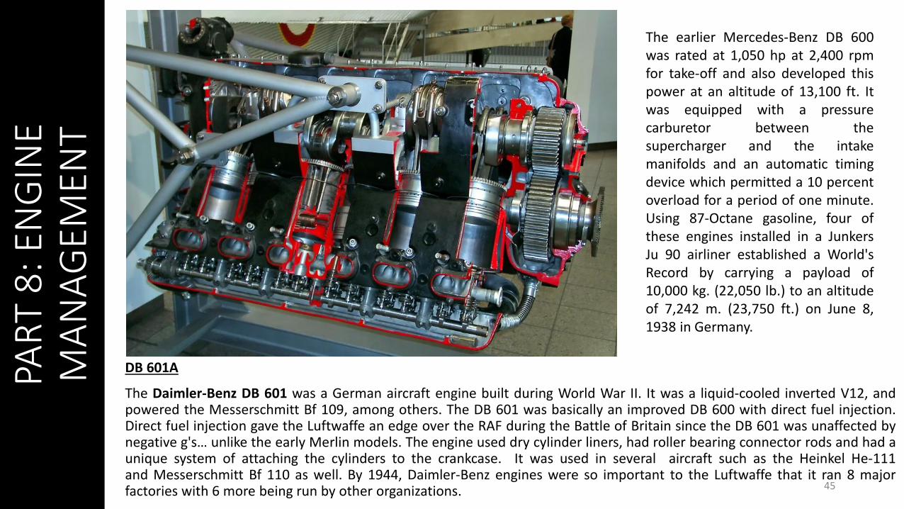
DB 601A
The Daimler-Benz DB 601 was a German aircraft engine built during World War II. It was a liquid-cooled inverted V12, andpowered the Messerschmitt Bf 109, among others. The DB 601 was basically an improved DB 600 with direct fuel injection.Direct fuel injection gave the Luftwaffe an edge over the RAF during the Battle of Britain since the DB 601 was unaffected bynegative g's… unlike the early Merlin models. The engine used dry cylinder liners, had roller bearing connector rods and had aunique system of attaching the cylinders to the crankcase. It was used in several aircraft such as the Heinkel He-111and Messerschmitt Bf 110 as well. By 1944, Daimler-Benz engines were so important to the Luftwaffe that it ran 8 majorfactories with 6 more being run by other organizations. 45
The earlier Mercedes-Benz DB 600was rated at 1,050 hp at 2,400 rpmfor take-off and also developed thispower at an altitude of 13,100 ft. Itwas equipped with a pressurecarburetor between thesupercharger and the intakemanifolds and an automatic timingdevice which permitted a 10 percentoverload for a period of one minute.Using 87-Octane gasoline, four ofthese engines installed in a JunkersJu 90 airliner established a World'sRecord by carrying a payload of10,000 kg. (22,050 lb.) to an altitudeof 7,242 m. (23,750 ft.) on June 8,1938 in Germany.

PAR
T 8
: EN
GIN
E M
AN
AG
EMEN
T
46
Comparison with the British engines
A cardinal fault of the Bf.109E - one which was corrected in the F and G models - was the design of the supercharger airintake. The unit on the Emil was close to the fuselage and ingested the "dirty" boundary layer air which scrubbed along thecowling surface. As a result, the supercharger ram recovery was 37.5% compared with the Spitfire's 50%. The lower ramrecovery meant that the critical altitude was reached at a lower altitude. Had the later design been used on the Bf.109E, asmuch as 1000 ft may have been gained in ceiling and in best combat altitude. This would have nullified much of theSpitfire's performance advantage at height.
Another important difference between the DB engines and the early Merlin engines lay in the supercharger design. Theearly Merlin engines were equipped with gear-driven single-speed, single-stage units. The supercharger had to be throttlesback at low altitude to avoid over-boosting the engine. As altitude increased, more and more of the superchargercapability was used and engine horsepower continued to increase until critical altitude was reached, after which power felloff rapidly.
The DB601A engine, on the other hand, was equipped with a single-stage supercharger with a hydraulic or fluid clutch.While heavier and more complex than the gear-driven clutch, this unit had the capability of operating at an infinitenumber of speed ratios. This meant that the supercharger could be slowed down without choking it and far more powerwas delivered at lower altitudes. As the Bf.110 flew higher, an aneroid control caused the supercharger to run faster tocompensate for the decreased density of the air. The variable speed characteristics of this supercharger are obtainedthrough slippage, so it was necessary for the Bf.110 cooling system to contain more oil for cooling.
47
PAR
T 8
: EN
GIN
E M
AN
AG
EMEN
T
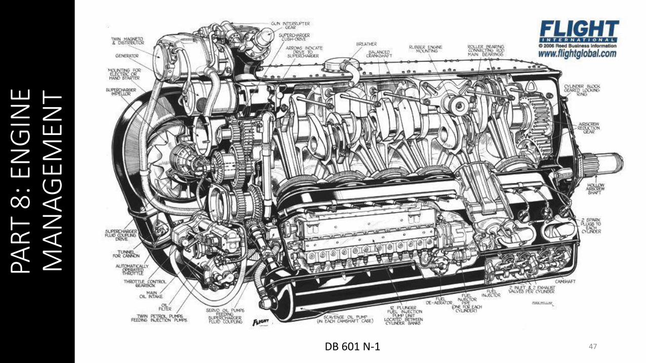
DB 601 N-1
48
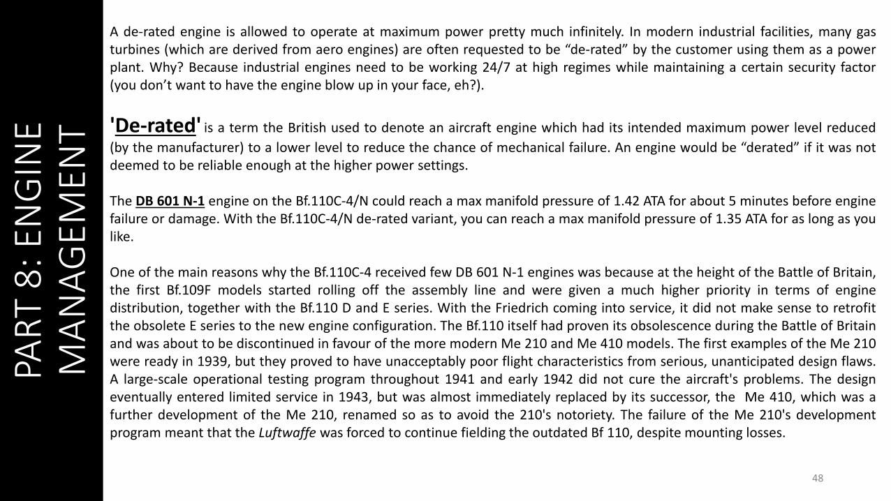
A de-rated engine is allowed to operate at maximum power pretty much infinitely. In modern industrial facilities, many gasturbines (which are derived from aero engines) are often requested to be “de-rated” by the customer using them as a powerplant. Why? Because industrial engines need to be working 24/7 at high regimes while maintaining a certain security factor(you don’t want to have the engine blow up in your face, eh?).
'De-rated' is a term the British used to denote an aircraft engine which had its intended maximum power level reduced
(by the manufacturer) to a lower level to reduce the chance of mechanical failure. An engine would be “derated” if it was notdeemed to be reliable enough at the higher power settings.
The DB 601 N-1 engine on the Bf.110C-4/N could reach a max manifold pressure of 1.42 ATA for about 5 minutes before enginefailure or damage. With the Bf.110C-4/N de-rated variant, you can reach a max manifold pressure of 1.35 ATA for as long as youlike.
One of the main reasons why the Bf.110C-4 received few DB 601 N-1 engines was because at the height of the Battle of Britain,the first Bf.109F models started rolling off the assembly line and were given a much higher priority in terms of enginedistribution, together with the Bf.110 D and E series. With the Friedrich coming into service, it did not make sense to retrofitthe obsolete E series to the new engine configuration. The Bf.110 itself had proven its obsolescence during the Battle of Britainand was about to be discontinued in favour of the more modern Me 210 and Me 410 models. The first examples of the Me 210were ready in 1939, but they proved to have unacceptably poor flight characteristics from serious, unanticipated design flaws.A large-scale operational testing program throughout 1941 and early 1942 did not cure the aircraft's problems. The designeventually entered limited service in 1943, but was almost immediately replaced by its successor, the Me 410, which was afurther development of the Me 210, renamed so as to avoid the 210's notoriety. The failure of the Me 210's developmentprogram meant that the Luftwaffe was forced to continue fielding the outdated Bf 110, despite mounting losses.
PAR
T 8
: EN
GIN
E M
AN
AG
EMEN
T

49
(Unit) Bf.110
C-2
Bf.110
C-4
Bf.110
C-4/N DERATED
Bf.110
C-4/N
Bf.110
C-7
Bf.110
C-7 LATE
TEMPERATURESWater Rad Min
Max
Deg C 6090
6090
60100
60100
6090
6090
Oil Rad (OUTBOUND) MinMax
Deg C 4085
4085
40105
40105
4085
4085
During a mission, the flight lead usually calls out his enginesettings once in a while for the pilots to know what settingsthey should use. You can read your engine settings from thegauges in the cockpit or from an info window.
• The RPM indicator (1) shows 1200 RPM. The manifold pressure (2) reads 0.83 ATA. The oil (3) and water (4) radiators can be approximated from the crank position or read from the info window in %. Note: 100 % = fully open
• The resulting RPM is affected by both manifold pressureand prop pitch (5). 12:00 Pitch is fully fine, and generatesmaximum RPM.
• Radiator settings:• 65-75 % WATER / 50-60 % OIL during normal level flight (1.2 ATA) • 75-100 % WATER / 60 % OIL during shallow climb (1.2 ATA)• 85-100 % WATER / 85 % OIL during steep climb (Full power)• 50-100 % WATER / 40 % OIL for WEP level flight (when extending or pursued)• 65-75 % WATER / 50 % OIL for full throttle no WEP (extending or pursued)• 100 % WATER / 100 % OIL during takeoff & landing
1
2
3
4
5PA
RT
8: E
NG
INE
MA
NA
GEM
ENT
Red notches indicate “d” (infinite), “30 min” and “5 min” engine settings.
GAUGE IS ON THE ENGINE ITSELF!
50
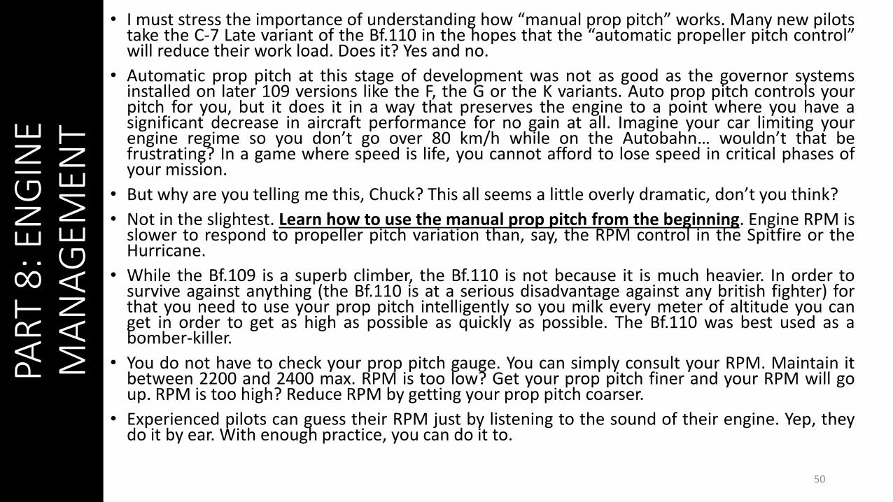
• I must stress the importance of understanding how “manual prop pitch” works. Many new pilotstake the C-7 Late variant of the Bf.110 in the hopes that the “automatic propeller pitch control”will reduce their work load. Does it? Yes and no.
• Automatic prop pitch at this stage of development was not as good as the governor systemsinstalled on later 109 versions like the F, the G or the K variants. Auto prop pitch controls yourpitch for you, but it does it in a way that preserves the engine to a point where you have asignificant decrease in aircraft performance for no gain at all. Imagine your car limiting yourengine regime so you don’t go over 80 km/h while on the Autobahn… wouldn’t that befrustrating? In a game where speed is life, you cannot afford to lose speed in critical phases ofyour mission.
• But why are you telling me this, Chuck? This all seems a little overly dramatic, don’t you think?
• Not in the slightest. Learn how to use the manual prop pitch from the beginning. Engine RPM isslower to respond to propeller pitch variation than, say, the RPM control in the Spitfire or theHurricane.
• While the Bf.109 is a superb climber, the Bf.110 is not because it is much heavier. In order tosurvive against anything (the Bf.110 is at a serious disadvantage against any british fighter) forthat you need to use your prop pitch intelligently so you milk every meter of altitude you canget in order to get as high as possible as quickly as possible. The Bf.110 was best used as abomber-killer.
• You do not have to check your prop pitch gauge. You can simply consult your RPM. Maintain itbetween 2200 and 2400 max. RPM is too low? Get your prop pitch finer and your RPM will goup. RPM is too high? Reduce RPM by getting your prop pitch coarser.
• Experienced pilots can guess their RPM just by listening to the sound of their engine. Yep, theydo it by ear. With enough practice, you can do it to.
PAR
T 8
: EN
GIN
E M
AN
AG
EMEN
T
51
PAR
T 8
: EN
GIN
E M
AN
AG
EMEN
T
52
PAR
T 8
: EN
GIN
E M
AN
AG
EMEN
T
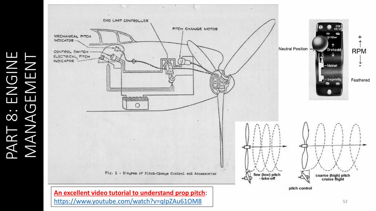
An excellent video tutorial to understand prop pitch:https://www.youtube.com/watch?v=qIpZAu61OM8
PAR
T 8
: EN
GIN
E M
AN
AG
EMEN
T
53EIN = ONFUEL TRANSFER!
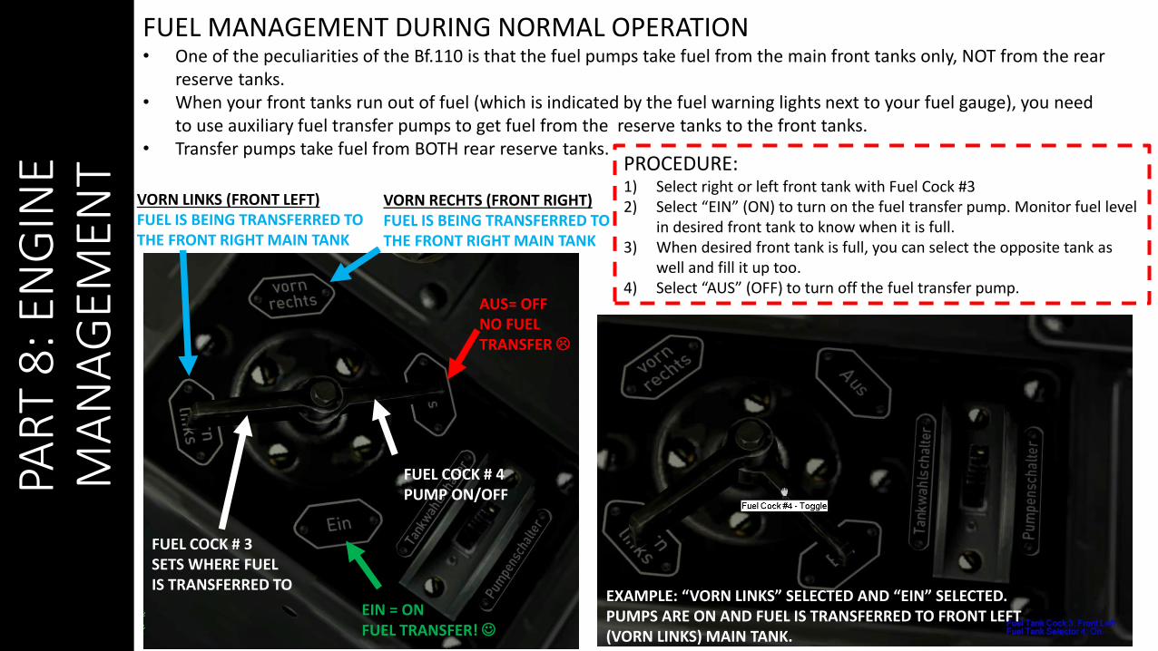
FUEL MANAGEMENT DURING NORMAL OPERATION• One of the peculiarities of the Bf.110 is that the fuel pumps take fuel from the main front tanks only, NOT from the rear
reserve tanks.• When your front tanks run out of fuel (which is indicated by the fuel warning lights next to your fuel gauge), you need
to use auxiliary fuel transfer pumps to get fuel from the reserve tanks to the front tanks.• Transfer pumps take fuel from BOTH rear reserve tanks.
AUS= OFFNO FUEL TRANSFER
VORN RECHTS (FRONT RIGHT)FUEL IS BEING TRANSFERRED TO THE FRONT RIGHT MAIN TANK
VORN LINKS (FRONT LEFT)FUEL IS BEING TRANSFERRED TO THE FRONT RIGHT MAIN TANK
PROCEDURE: 1) Select right or left front tank with Fuel Cock #3 2) Select “EIN” (ON) to turn on the fuel transfer pump. Monitor fuel level
in desired front tank to know when it is full.3) When desired front tank is full, you can select the opposite tank as
well and fill it up too. 4) Select “AUS” (OFF) to turn off the fuel transfer pump.
FUEL COCK # 4PUMP ON/OFF
FUEL COCK # 3SETS WHERE FUELIS TRANSFERRED TO
EXAMPLE: “VORN LINKS” SELECTED AND “EIN” SELECTED. PUMPS ARE ON AND FUEL IS TRANSFERRED TO FRONT LEFT (VORN LINKS) MAIN TANK.
PAR
T 8
: EN
GIN
E M
AN
AG
EMEN
T
54
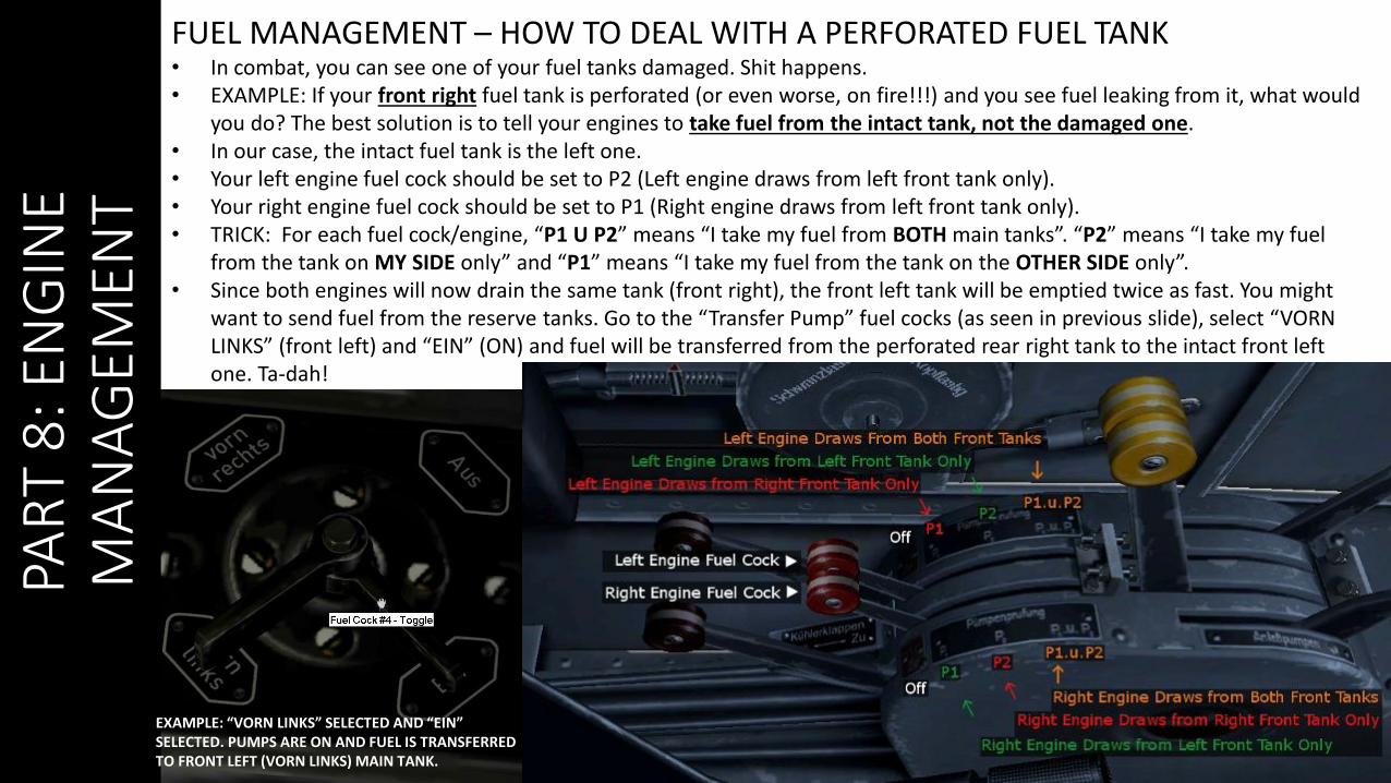
FUEL MANAGEMENT – HOW TO DEAL WITH A PERFORATED FUEL TANK• In combat, you can see one of your fuel tanks damaged. Shit happens.• EXAMPLE: If your front right fuel tank is perforated (or even worse, on fire!!!) and you see fuel leaking from it, what would
you do? The best solution is to tell your engines to take fuel from the intact tank, not the damaged one.• In our case, the intact fuel tank is the left one.• Your left engine fuel cock should be set to P2 (Left engine draws from left front tank only).• Your right engine fuel cock should be set to P1 (Right engine draws from left front tank only).• TRICK: For each fuel cock/engine, “P1 U P2” means “I take my fuel from BOTH main tanks”. “P2” means “I take my fuel
from the tank on MY SIDE only” and “P1” means “I take my fuel from the tank on the OTHER SIDE only”. • Since both engines will now drain the same tank (front right), the front left tank will be emptied twice as fast. You might
want to send fuel from the reserve tanks. Go to the “Transfer Pump” fuel cocks (as seen in previous slide), select “VORN LINKS” (front left) and “EIN” (ON) and fuel will be transferred from the perforated rear right tank to the intact front left one. Ta-dah!
EXAMPLE: “VORN LINKS” SELECTED AND “EIN” SELECTED. PUMPS ARE ON AND FUEL IS TRANSFERRED TO FRONT LEFT (VORN LINKS) MAIN TANK.
PAR
T 9
: AIR
CR
AFT
P
ERFO
RM
AN
CE
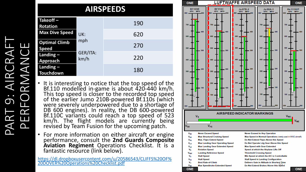
• It is interesting to notice that the top speed of theBf.110 modelled in-game is about 420-440 km/h.This top speed is closer to the recorded top speedof the earlier Jumo 210B-powered Bf.110s (whichwere severely underpowered due to a shortage ofDB 600 engines). In reality, the DB 600-poweredBf.110C variants could reach a top speed of 523km/h. The flight models are currently beingrevised by Team Fusion for the upcoming patch.
• For more information on either aircraft or engineperformance, consult the 2nd Guards CompositeAviation Regiment Operations Checklist. It is afantastic resource (link below).
https://dl.dropboxusercontent.com/u/20586543/CLIFFS%20OF%20DOVER%20Operations%20Checklist.pdf 55
AIRSPEEDSTakeoff –Rotation
UK:mph
GER/ITA: km/h
190
Max Dive Speed 620Optimal Climb Speed
270
Landing –Approach
220
Landing –Touchdown
180
PAR
T 9
: AIR
CR
AFT
P
ERFO
RM
AN
CE
56
PAR
T 9
: AIR
CR
AFT
P
ERFO
RM
AN
CE
57

PAR
T 9
: AIR
CR
AFT
P
ERFO
RM
AN
CE
58
Match-Ups and Relative Performance (from II./KG53 Bomber Schule)
The Bf.110 was best used as a fighter-bomber, a ground attack aircraft or a bomber hunter. Bf.110 squadronspaid a very heavy price when they were sent against fighter squadrons during the Battle of Britain. The lossestaken by the 110 forced german high command to revisit their approach to the role of a heavy fighter.
Bf.110C vs HurricaneThis is the only plane where you have a speed advantage. In fact, you can actually outclimb this plane. Assuming that youstart with an energy advantage, you can actually take on a Hurricane and win reliably. However, where there are Hurricanes,there are Spitfires. If you stumble upon a Hurricane all by itself, and you have an energy advantage, savor the moment.
Bf.110C vs SpitfireDeath on wings. There is no area where the Spitfire has a disadvantage except firepower. Engage only with caution, and writeyour will if a Spitfire shows above you and chooses you as his next meal. If you have a shot on one, take it (unless he doesn'tknow you're there and you can escape first). You won't get another, so blow your ammo supply on him to try to get a fewlucky hits. If a couple 20mm land on his wing, he's much less of a threat and may decide to leave. There's a reason this planehas a 3:1 kill/loss ratio on the bf-110C.
SummaryIn the air-to-air role it does not sound too good for the 110 driver. But all is not lost when you have a partner. Goodcommunication and airmanship can overcome the single bandit. On an active server, like ATAG, most of the Red jockeys onlyknow one-speed - flat out! Judicious use of speed, in a bf109 or bf110, can see you turning the tables on your opponent whois always presuming they have the better turn rate. A barrel roll, with deceleration at the top of the roll, may cause anovershoot. Of course, with the 110 you always have to be aware of its slow acceleration so if you decide to play make sureyou have some height
59
PAR
T 9
: AIR
CR
AFT
P
ERFO
RM
AN
CE
FOR ADDITIONAL INFORMATION ON THE BF.110, CHECK OUT THESE YOUTUBE CHANNELS. THESE GUYS COMPLETELY UNDERSTAND HOW TO FLY THE BF.110 AND EXPLAIN IT CLEARLY AND EFFORTLESSLY.
APEOFTHEYEARChannel:https://www.youtube.com/user/Apeoftheyear/featuredTutorials: https://www.youtube.com/playlist?list=PLUyEbp1iw_PrgHx7nji2ohQyhHqBPluh1Bf.110 Tutorial:https://www.youtube.com/watch?v=8DhS9kiTPDw
JG4_KARAYAChannel:https://www.youtube.com/user/JG52KarayaBf.110 Tutorial: https://www.youtube.com/watch?v=QsD4bpkgTPs
PAR
T 1
0: A
UTO
PIL
OT
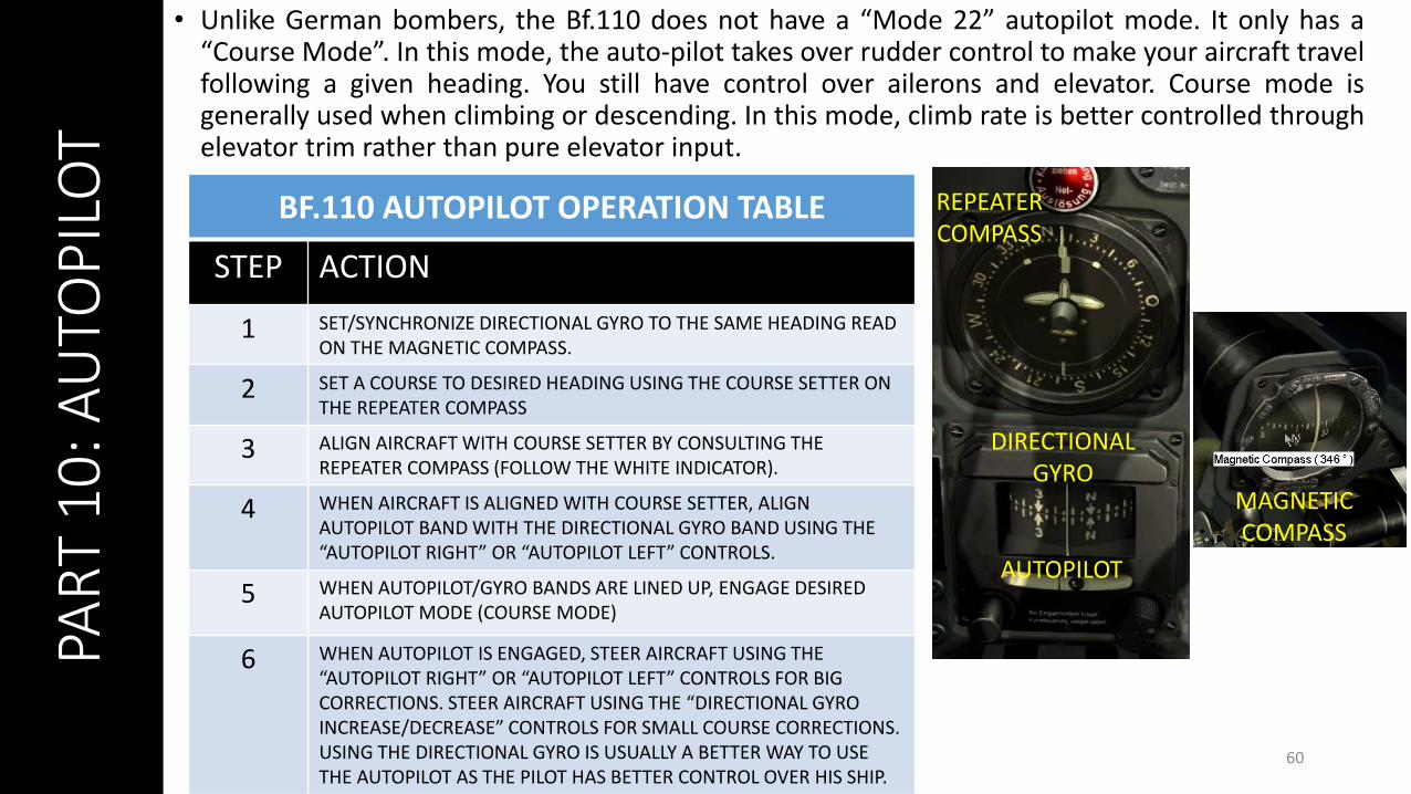
• Unlike German bombers, the Bf.110 does not have a “Mode 22” autopilot mode. It only has a“Course Mode”. In this mode, the auto-pilot takes over rudder control to make your aircraft travelfollowing a given heading. You still have control over ailerons and elevator. Course mode isgenerally used when climbing or descending. In this mode, climb rate is better controlled throughelevator trim rather than pure elevator input.
60
BF.110 AUTOPILOT OPERATION TABLE
STEP ACTION
1 SET/SYNCHRONIZE DIRECTIONAL GYRO TO THE SAME HEADING READ ON THE MAGNETIC COMPASS.
2 SET A COURSE TO DESIRED HEADING USING THE COURSE SETTER ON THE REPEATER COMPASS
3 ALIGN AIRCRAFT WITH COURSE SETTER BY CONSULTING THE REPEATER COMPASS (FOLLOW THE WHITE INDICATOR).
4 WHEN AIRCRAFT IS ALIGNED WITH COURSE SETTER, ALIGN AUTOPILOT BAND WITH THE DIRECTIONAL GYRO BAND USING THE “AUTOPILOT RIGHT” OR “AUTOPILOT LEFT” CONTROLS.
5 WHEN AUTOPILOT/GYRO BANDS ARE LINED UP, ENGAGE DESIRED AUTOPILOT MODE (COURSE MODE)
6 WHEN AUTOPILOT IS ENGAGED, STEER AIRCRAFT USING THE “AUTOPILOT RIGHT” OR “AUTOPILOT LEFT” CONTROLS FOR BIG CORRECTIONS. STEER AIRCRAFT USING THE “DIRECTIONAL GYRO INCREASE/DECREASE” CONTROLS FOR SMALL COURSE CORRECTIONS. USING THE DIRECTIONAL GYRO IS USUALLY A BETTER WAY TO USE THE AUTOPILOT AS THE PILOT HAS BETTER CONTROL OVER HIS SHIP.
MAGNETIC COMPASS
AUTOPILOT
DIRECTIONAL GYRO
REPEATER COMPASS
PAR
T 1
0: A
UTO
PIL
OT
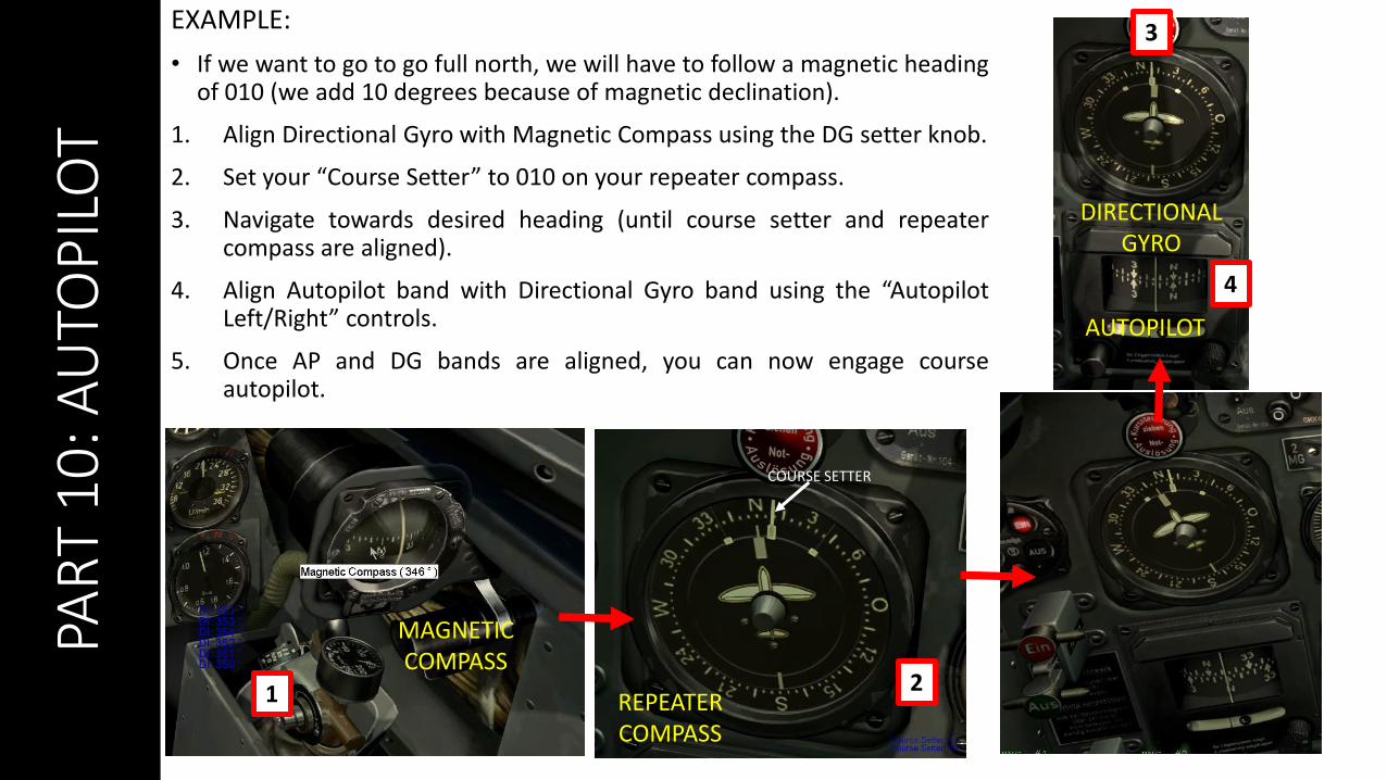
EXAMPLE:
• If we want to go to go full north, we will have to follow a magnetic headingof 010 (we add 10 degrees because of magnetic declination).
1. Align Directional Gyro with Magnetic Compass using the DG setter knob.
2. Set your “Course Setter” to 010 on your repeater compass.
3. Navigate towards desired heading (until course setter and repeatercompass are aligned).
4. Align Autopilot band with Directional Gyro band using the “AutopilotLeft/Right” controls.
5. Once AP and DG bands are aligned, you can now engage courseautopilot.
61
MAGNETIC COMPASS
AUTOPILOT
DIRECTIONAL GYRO
REPEATER COMPASS
COURSE SETTER
1 2
3
4

About Magnetic DeclinationThe direction in which a compass needle points isknown as magnetic north. In general, this is notexactly the direction of the North Magnetic Pole(or of any other consistent location). Instead, thecompass aligns itself to the local geomagneticfield, which varies in a complex manner over theEarth's surface, as well as over time. The localangular difference between magnetic northand true north is called the magnetic declination.Most map coordinate systems are based on truenorth, and magnetic declination is often shownon map legends so that the direction of truenorth can be determined from north as indicatedby a compass.
This is the reason why in Cliffs of Dover, themagnetic compass needs to be “adjusted” to takeinto account this magnetic declination of themagnetic North pole (which is actually modelledin the sim, which is pretty neat).
In 1940, the magnetic declination required anadjustment of 10 degrees and 8 minutes. Weround that to 10 deg.
62
The movement of Earth's north magnetic pole
across the Canadian arctic, 1831–2007.
PAR
T 1
0: A
UTO
PIL
OT

63