Embed Size (px)
Citation preview
1Revision date: 04.14.17
©2017 ClearSpan™All Rights Reserved. Reproduction is prohibited without permission.
ClearSpan™ Curtain TubeSupport System (Manual Gearbox)
ATTENTION: This guide describes the assembly and installation of roll-up curtains. The design flexibility of these curtain systems allow for a variety of possible component and curtain combinations. The examples shown in this guide are presented to give the reader basic assembly and installation information. The actual curtain tube system may resemble what is presented, but differ in details.
Single and Double-Output
2 curtain tube system gearbox Revision date: 04.14.17
SAFETY PRECAUTIONS
• Wear eye protection.
• Wear head protection.
• Wear gloves when handling the pipe and brackets.
• Use a portable GFCI when working with power tools and cords.
WARNING: Exercise caution during installation. Strong winds can lift and blow the curtain during and after installation. Do not install the curtain during windy conditions or when such conditions are expected.
YOU MUST READ THIS DOCUMENT BEFORE YOU ASSEMBLE THE CURTAIN TUBE SUPPORT SYSTEM.
Thank you for purchasing this ClearSpan™ Curtain Tube Support System. These instructions include helpful hints and important information needed to safely assemble and properly maintain the curtain and related components. Please read these instructions before you begin. If you have any questions during the assembly, contact customer service.
Important Information
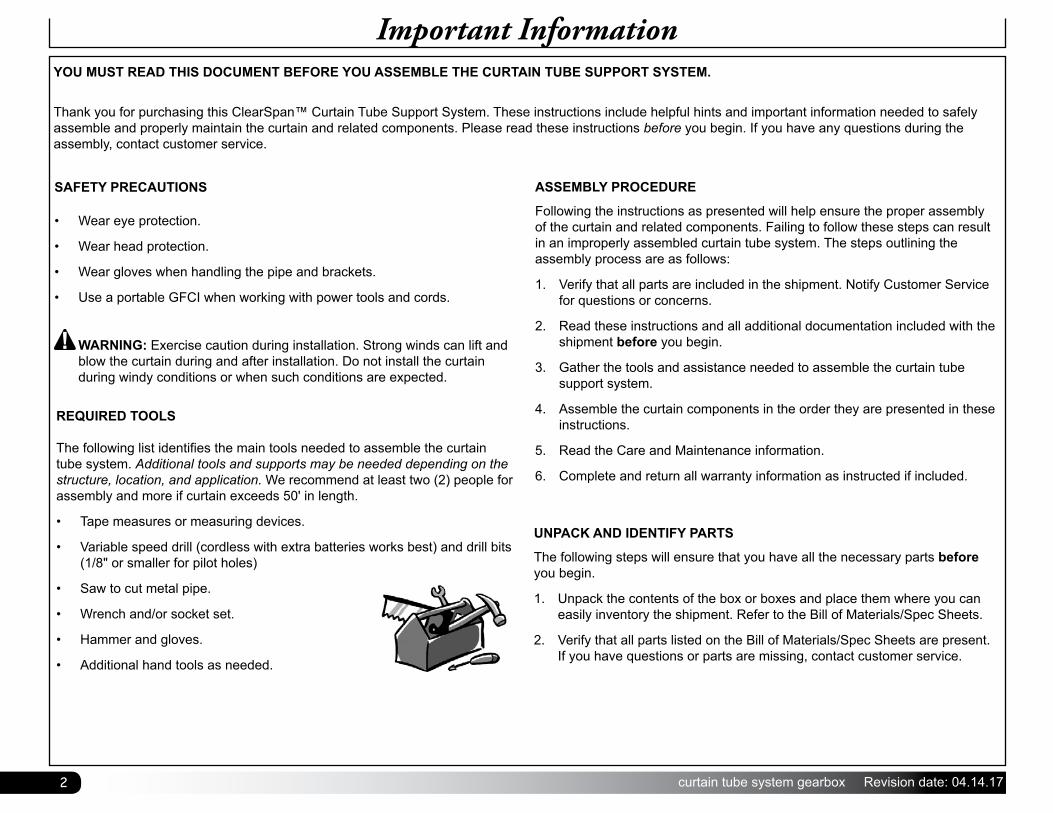
REQUIRED TOOLS The following list identifies the main tools needed to assemble the curtain tube system. Additional tools and supports may be needed depending on the structure, location, and application. We recommend at least two (2) people for assembly and more if curtain exceeds 50' in length.
• Tape measures or measuring devices.
• Variable speed drill (cordless with extra batteries works best) and drill bits (1/8" or smaller for pilot holes)
• Saw to cut metal pipe.
• Wrench and/or socket set.
• Hammer and gloves.
• Additional hand tools as needed.
ASSEMBLY PROCEDURE
Following the instructions as presented will help ensure the proper assembly of the curtain and related components. Failing to follow these steps can result in an improperly assembled curtain tube system. The steps outlining the assembly process are as follows:
1. Verify that all parts are included in the shipment. Notify Customer Service for questions or concerns.
2. Read these instructions and all additional documentation included with the shipment before you begin.
3. Gather the tools and assistance needed to assemble the curtain tube support system.
4. Assemble the curtain components in the order they are presented in these instructions.
5. Read the Care and Maintenance information.
6. Complete and return all warranty information as instructed if included.
UNPACK AND IDENTIFY PARTS
The following steps will ensure that you have all the necessary parts before you begin.
1. Unpack the contents of the box or boxes and place them where you can easily inventory the shipment. Refer to the Bill of Materials/Spec Sheets.
2. Verify that all parts listed on the Bill of Materials/Spec Sheets are present. If you have questions or parts are missing, contact customer service.
3Revision date: 04.14.17 curtain tube system gearbox
Important Information
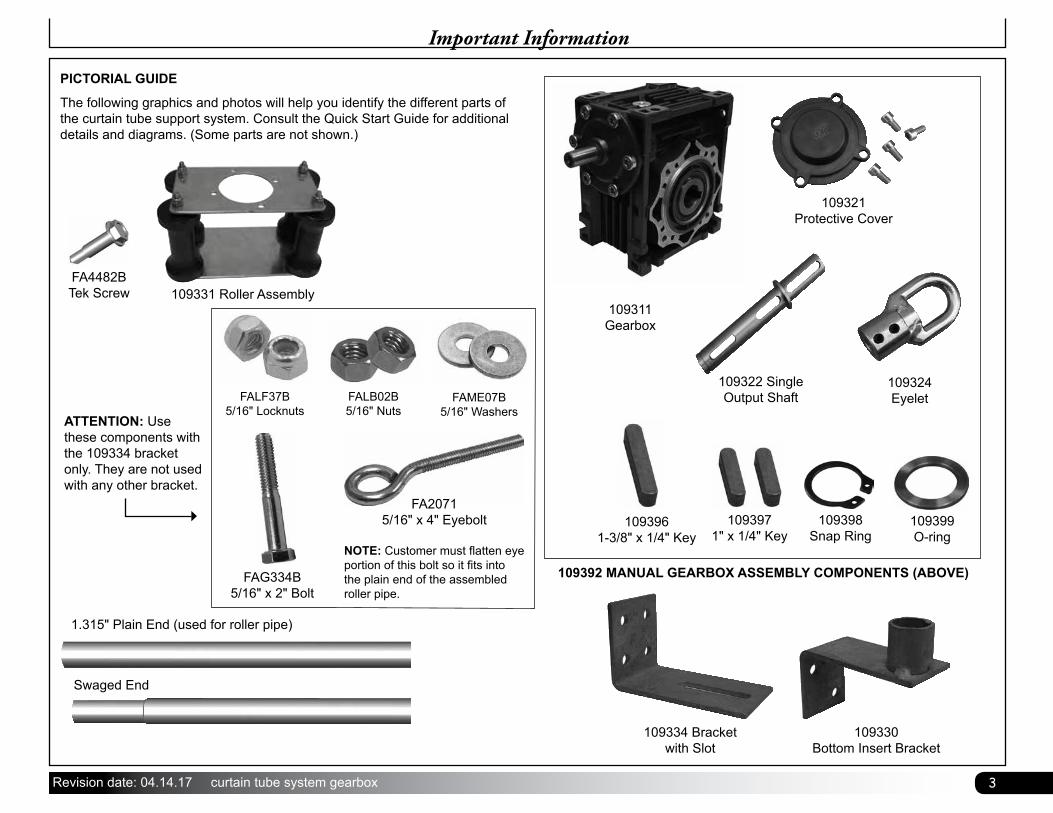
PICTORIAL GUIDE
The following graphics and photos will help you identify the different parts of the curtain tube support system. Consult the Quick Start Guide for additional details and diagrams. (Some parts are not shown.)
Swaged End
1.315" Plain End (used for roller pipe)
109392 MANUAL GEARBOX ASSEMBLY COMPONENTS (ABOVE)
109324Eyelet
109321Protective Cover
109322 SingleOutput Shaft
109311Gearbox
109399O-ring
109398Snap Ring
1093971" x 1/4" Key
1093961-3/8" x 1/4" Key
109330Bottom Insert Bracket
109334 Bracket with Slot
109331 Roller AssemblyFA4482BTek Screw
FAG334B5/16" x 2" Bolt
FALF37B5/16" Locknuts
FALB02B5/16" Nuts
FAME07B5/16" Washers
FA20715/16" x 4" Eyebolt
NOTE: Customer must flatten eye portion of this bolt so it fits into the plain end of the assembled roller pipe.
ATTENTION: Use these components with the 109334 bracket only. They are not used with any other bracket.
4 curtain tube system gearbox Revision date: 04.14.17
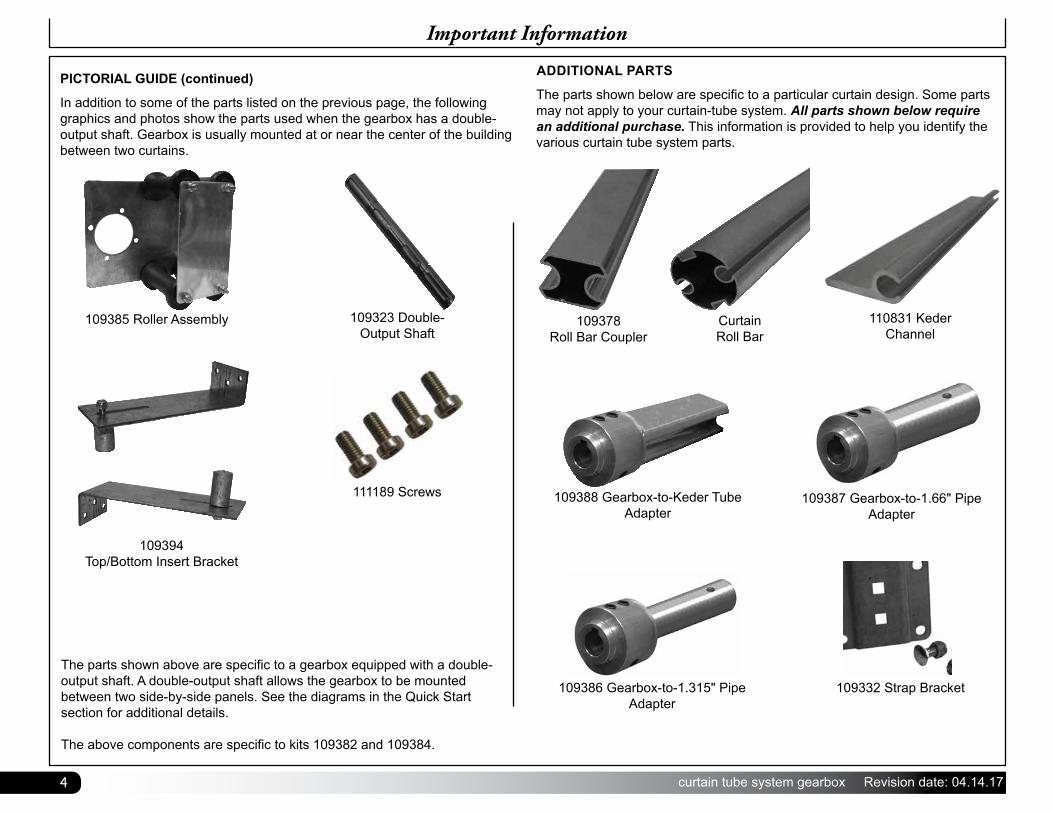
ADDITIONAL PARTS
The parts shown below are specific to a particular curtain design. Some parts may not apply to your curtain-tube system. All parts shown below require an additional purchase. This information is provided to help you identify the various curtain tube system parts.
Important Information
109378Roll Bar Coupler
CurtainRoll Bar
109388 Gearbox-to-Keder Tube Adapter
109387 Gearbox-to-1.66" Pipe Adapter
109332 Strap Bracket109386 Gearbox-to-1.315" Pipe Adapter
PICTORIAL GUIDE (continued)
In addition to some of the parts listed on the previous page, the following graphics and photos show the parts used when the gearbox has a double-output shaft. Gearbox is usually mounted at or near the center of the building between two curtains.
109385 Roller Assembly 109323 Double-Output Shaft
The parts shown above are specific to a gearbox equipped with a double-output shaft. A double-output shaft allows the gearbox to be mounted between two side-by-side panels. See the diagrams in the Quick Start section for additional details.
The above components are specific to kits 109382 and 109384.
110831 Keder Channel
111189 Screws
109394Top/Bottom Insert Bracket
5Revision date: 04.14.17 curtain tube system gearbox
CARE AND MAINTENANCE
Proper care and maintenance of your curtain tube support system will help to ensure reliable service. The following items identify areas that must be periodically checked to ensure that the components are maintained properly:
• Frequently check the curtain mount and mount support structure to verify that all components are tight and in good condition.
• Check all fasteners to verify that they remain tight.
• Inspect the gearbox and related mounting components regularly. Tighten all bolts and mounts as needed.
• Verify that all connections and connectors are secure. Tighten these if necessary. Replace all broken or missing components immediately.
• Check the curtain to verify that it is in good condition.
• Verify that nothing rubs against the curtain or prevents it from opening and closing as designed.
• When cleaning the panel, use tools that will not damage the material. Clean dirt and debris using mild soap and water. Do not use solvents.
• For replacement or missing parts, call 1-800-245-9881 for assistance.
Important Information
SPACE BELOW RESERVED FOR CUSTOMER NOTES
6 curtain tube system gearbox Revision date: 04.14.17
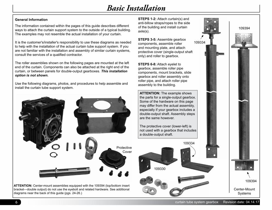
Basic InstallationGeneral Information
The information contained within the pages of this guide describes different ways to attach the curtain support system to the outside of a typical building. The examples may not resemble the actual installation of your curtain.
It is the customer's/installer's responsibility to use these diagrams as needed to help with the installation of the actual curtain tube support system. If you are not familiar with the installation and assembly of similar curtain systems, consult the services of a qualified contractor.
The roller assemblies shown on the following pages are mounted at the left end of the curtain. Components can also be attached at the right end of the curtain, or between panels for double-output gearboxes. This installation option is not shown.
Use the following diagrams, photos, and procedures to help assemble and install the curtain tube support system.
Protective Cover
ATTENTION: Center-mount assemblies equipped with the 109394 (top/bottom insert bracket—double output) do not use the eyebolt and related hardware. See additional diagrams near the back of this guide (pgs. 24-26.)
Center-Mount Systems
109394
109394
STEPS 1-2: Attach curtain(s) and anti-billow straps/ropes to the side of the building and install curtain axle(s).
STEPS 3-5: Assemble gearbox components, assemble roller and mounting plate, and attach protective cover (single-output shaft only) and roller to gearbox.
STEPS 6-8: Attach eyelet to gearbox, assemble roller pipe components, mount brackets, slide gearbox and roller assembly onto roller pipe, and attach roller pipe assembly to the building.
ATTENTION: The example shows the parts for a single-output gearbox. Some of the hardware on this page may differ from the actual assembly, especially if your gearbox includes a double-output shaft. Assembly steps are the same however.
The protective cover (lower-left) is not used with a gearbox that includes a double-output shaft.
109334
109330
109334
7Revision date: 04.14.17 curtain tube system gearbox
1Installation
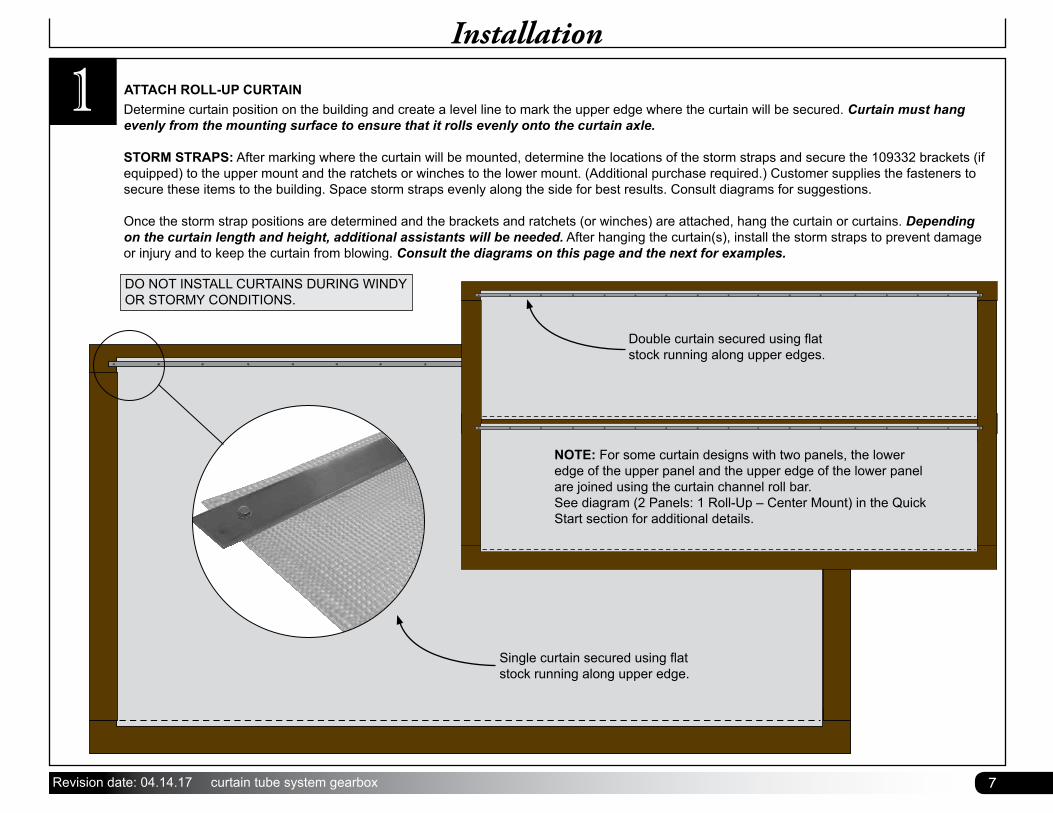
Determine curtain position on the building and create a level line to mark the upper edge where the curtain will be secured. Curtain must hang evenly from the mounting surface to ensure that it rolls evenly onto the curtain axle.
STORM STRAPS: After marking where the curtain will be mounted, determine the locations of the storm straps and secure the 109332 brackets (if equipped) to the upper mount and the ratchets or winches to the lower mount. (Additional purchase required.) Customer supplies the fasteners to secure these items to the building. Space storm straps evenly along the side for best results. Consult diagrams for suggestions.
Once the storm strap positions are determined and the brackets and ratchets (or winches) are attached, hang the curtain or curtains. Depending on the curtain length and height, additional assistants will be needed. After hanging the curtain(s), install the storm straps to prevent damage or injury and to keep the curtain from blowing. Consult the diagrams on this page and the next for examples.
ATTACH ROLL-UP CURTAIN
DO NOT INSTALL CURTAINS DURING WINDY OR STORMY CONDITIONS.
Single curtain secured using flat stock running along upper edge.
Double curtain secured using flat stock running along upper edges.
NOTE: For some curtain designs with two panels, the lower edge of the upper panel and the upper edge of the lower panel are joined using the curtain channel roll bar. See diagram (2 Panels: 1 Roll-Up – Center Mount) in the Quick Start section for additional details.
8 curtain tube system gearbox Revision date: 04.14.17
1Installation
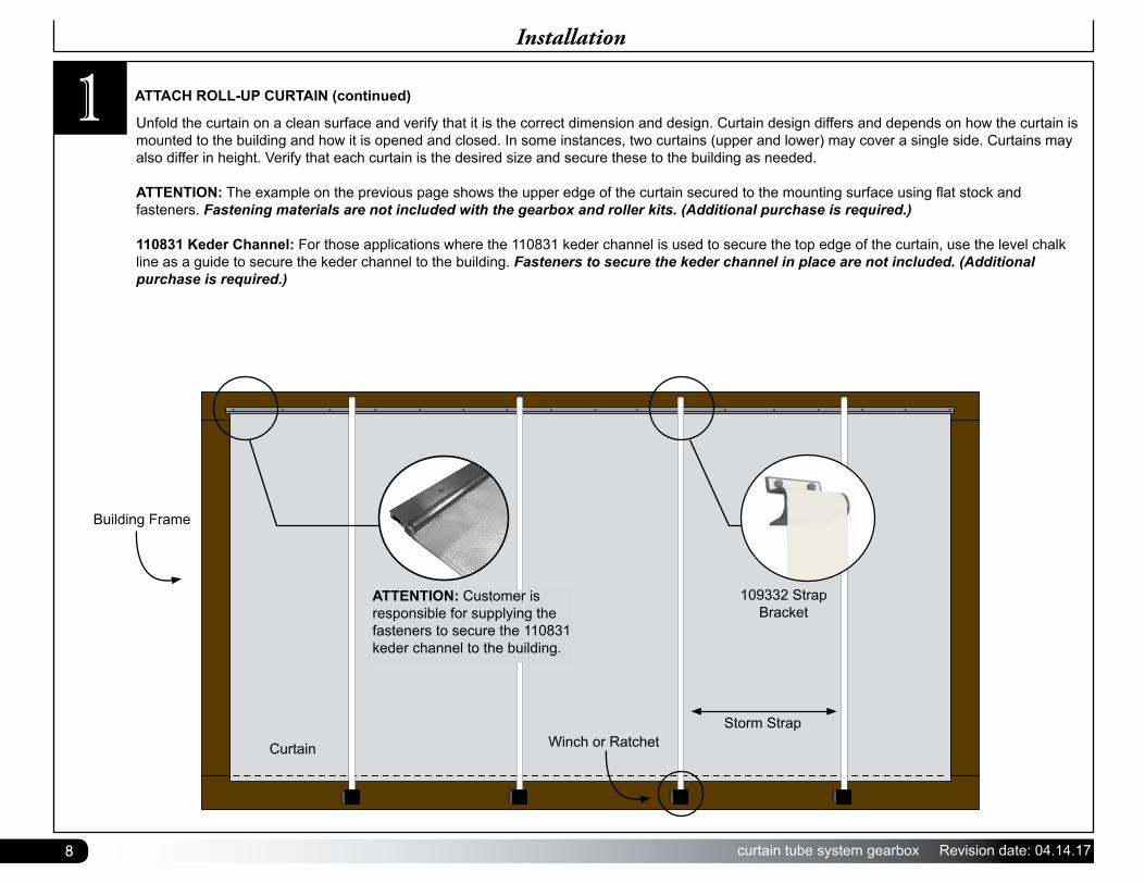
Unfold the curtain on a clean surface and verify that it is the correct dimension and design. Curtain design differs and depends on how the curtain is mounted to the building and how it is opened and closed. In some instances, two curtains (upper and lower) may cover a single side. Curtains may also differ in height. Verify that each curtain is the desired size and secure these to the building as needed.
ATTENTION: The example on the previous page shows the upper edge of the curtain secured to the mounting surface using flat stock and fasteners. Fastening materials are not included with the gearbox and roller kits. (Additional purchase is required.)
110831 Keder Channel: For those applications where the 110831 keder channel is used to secure the top edge of the curtain, use the level chalk line as a guide to secure the keder channel to the building. Fasteners to secure the keder channel in place are not included. (Additional purchase is required.)
ATTACH ROLL-UP CURTAIN (continued)
Curtain
109332 Strap Bracket
Storm StrapWinch or Ratchet
Building Frame
ATTENTION: Customer is responsible for supplying the fasteners to secure the 110831 keder channel to the building.
9Revision date: 04.14.17 curtain tube system gearbox
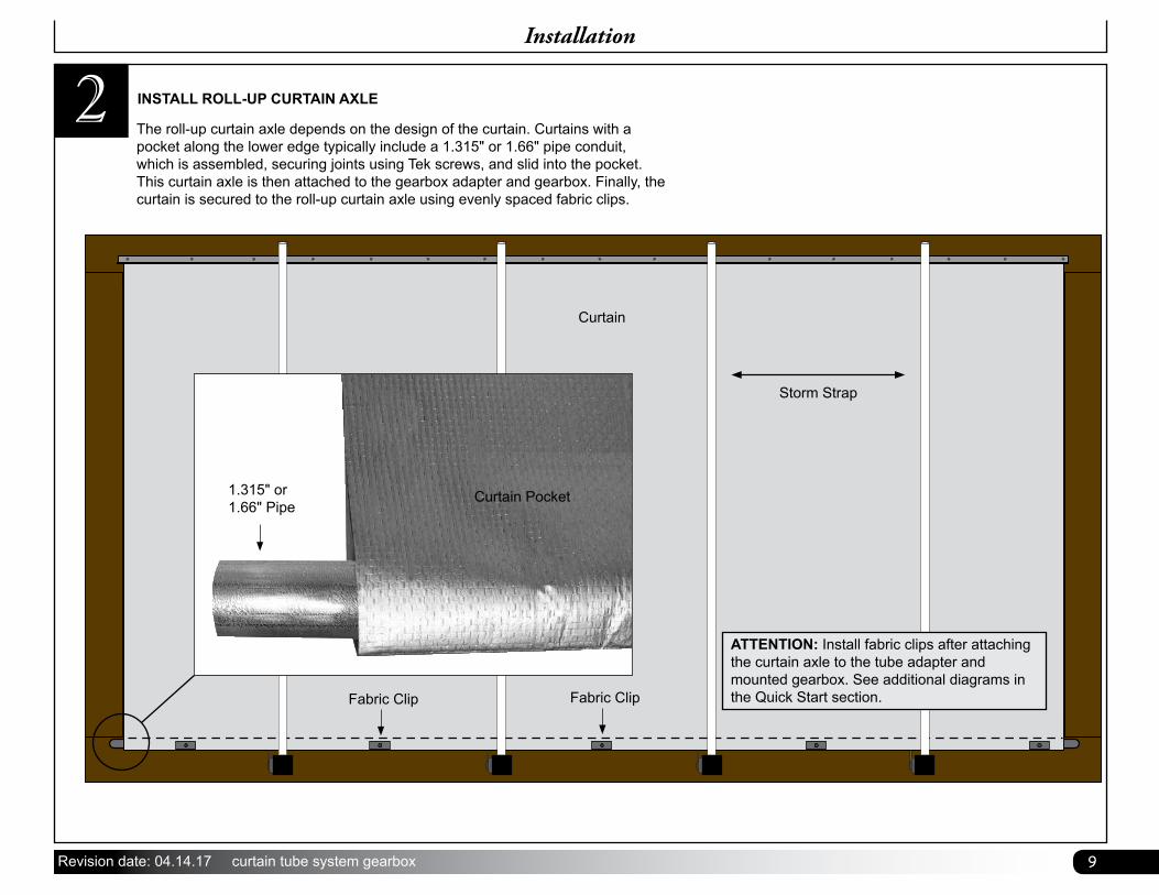
2 INSTALL ROLL-UP CURTAIN AXLE
The roll-up curtain axle depends on the design of the curtain. Curtains with a pocket along the lower edge typically include a 1.315" or 1.66" pipe conduit, which is assembled, securing joints using Tek screws, and slid into the pocket. This curtain axle is then attached to the gearbox adapter and gearbox. Finally, the curtain is secured to the roll-up curtain axle using evenly spaced fabric clips.
Installation
ATTENTION: Install fabric clips after attaching the curtain axle to the tube adapter and mounted gearbox. See additional diagrams in the Quick Start section.Fabric Clip
1.315" or1.66" Pipe
Curtain Pocket
Fabric Clip
Curtain
Storm Strap
10 curtain tube system gearbox Revision date: 04.14.17
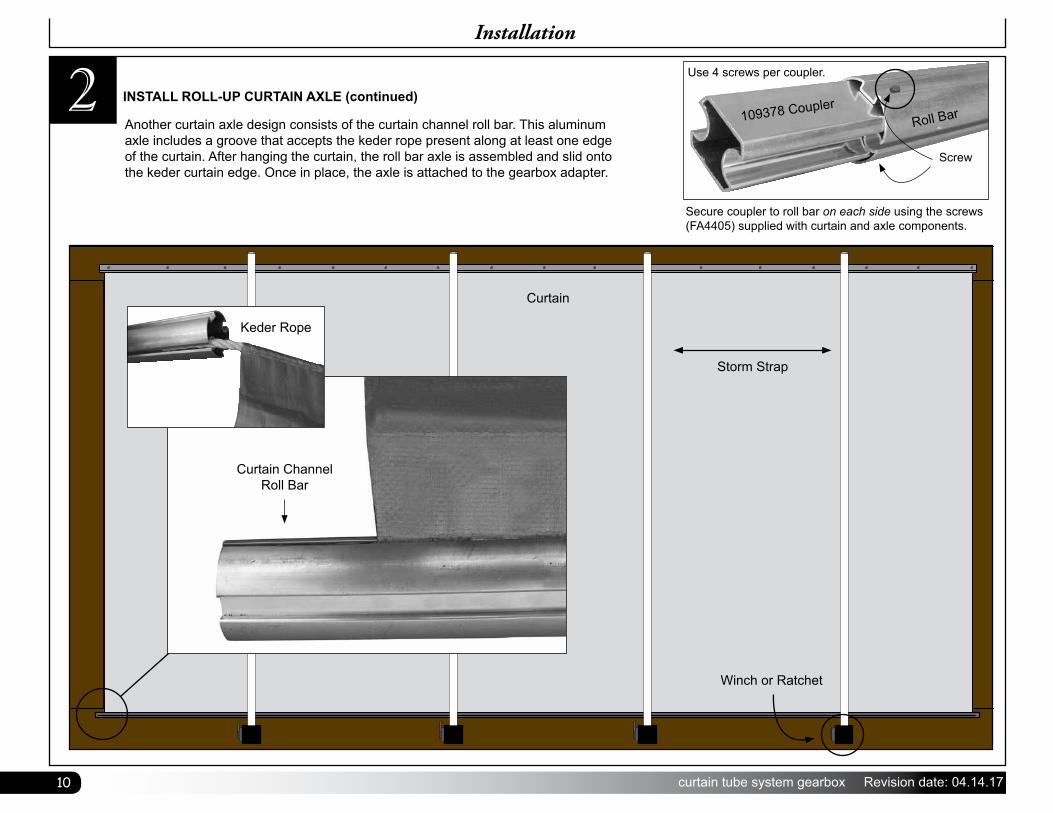
Another curtain axle design consists of the curtain channel roll bar. This aluminum axle includes a groove that accepts the keder rope present along at least one edge of the curtain. After hanging the curtain, the roll bar axle is assembled and slid onto the keder curtain edge. Once in place, the axle is attached to the gearbox adapter.
INSTALL ROLL-UP CURTAIN AXLE (continued)2Installation
Curtain Channel Roll Bar
Keder Rope
Curtain
Storm Strap
Winch or Ratchet
Secure coupler to roll bar on each side using the screws (FA4405) supplied with curtain and axle components.
109378 CouplerRoll Bar
Use 4 screws per coupler.
Screw
11Revision date: 04.14.17 curtain tube system gearbox
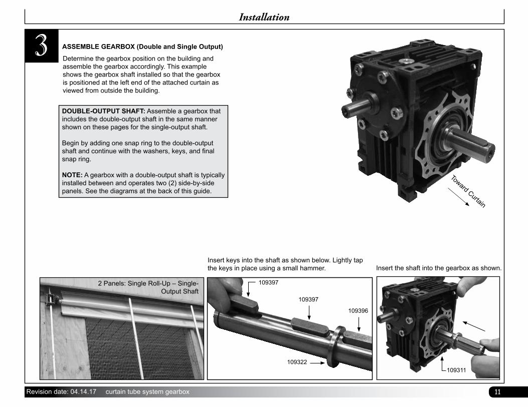
3
Insert keys into the shaft as shown below. Lightly tap the keys in place using a small hammer.
109397
109397
109396
109322
Insert the shaft into the gearbox as shown.
109311
Determine the gearbox position on the building and assemble the gearbox accordingly. This example shows the gearbox shaft installed so that the gearbox is positioned at the left end of the attached curtain as viewed from outside the building.
Toward Curtain
ASSEMBLE GEARBOX (Double and Single Output)
Installation
DOUBLE-OUTPUT SHAFT: Assemble a gearbox that includes the double-output shaft in the same manner shown on these pages for the single-output shaft.
Begin by adding one snap ring to the double-output shaft and continue with the washers, keys, and final snap ring.
NOTE: A gearbox with a double-output shaft is typically installed between and operates two (2) side-by-side panels. See the diagrams at the back of this guide.
2 Panels: Single Roll-Up – Single- Output Shaft
12 curtain tube system gearbox Revision date: 04.14.17
3
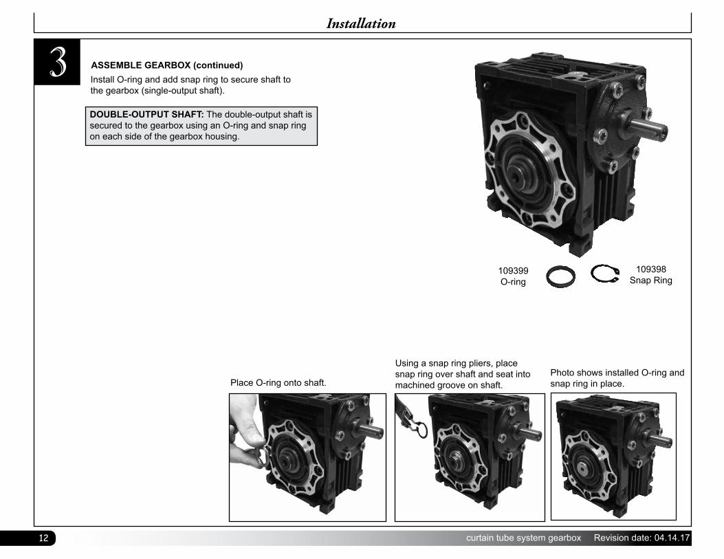
Place O-ring onto shaft.
Using a snap ring pliers, place snap ring over shaft and seat into machined groove on shaft.
Photo shows installed O-ring and snap ring in place.
109399O-ring
109398Snap Ring
Install O-ring and add snap ring to secure shaft to the gearbox (single-output shaft).
ASSEMBLE GEARBOX (continued)
Installation
DOUBLE-OUTPUT SHAFT: The double-output shaft is secured to the gearbox using an O-ring and snap ring on each side of the gearbox housing.
13Revision date: 04.14.17 curtain tube system gearbox
Installation
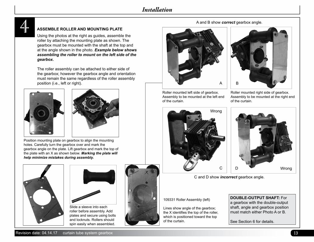
4Using the photos at the right as guides, assemble the roller by attaching the mounting plate as shown. The gearbox must be mounted with the shaft at the top and at the angle shown in the photo. Example below shows assembling the roller to mount on the left side of the gearbox.
The roller assembly can be attached to either side of the gearbox; however the gearbox angle and orientation must remain the same regardless of the roller assembly position (i.e., left or right).
ASSEMBLE ROLLER AND MOUNTING PLATE
Slide a sleeve into each roller before assembly. Add plates and secure using bolts and locknuts. Rollers should spin easily when assembled.
Position mounting plate on gearbox to align the mounting holes. Carefully turn the gearbox over and mark the gearbox angle on the plate. Lift gearbox and mark the top of the plate with an X as shown below. Marking the plate will help minimize mistakes during assembly.
A and B show correct gearbox angle.
Roller mounted left side of gearbox. Assembly to be mounted at the left end of the curtain.
109331 Roller Assembly (left)
Lines show angle of the gearbox; the X identifies the top of the roller, which is positioned toward the top of the curtain.
Roller mounted right side of gearbox. Assembly to be mounted at the right end of the curtain.
A B
C and D show incorrect gearbox angle.
C D Wrong
Wrong
DOUBLE-OUTPUT SHAFT: For a gearbox with the double-output shaft, angle and gearbox position must match either Photo A or B.
See Section 6 for details.
14 curtain tube system gearbox Revision date: 04.14.17
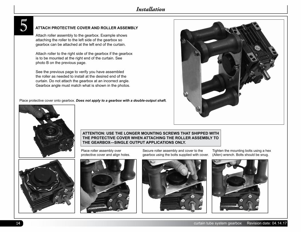
5Attach roller assembly to the gearbox. Example shows attaching the roller to the left side of the gearbox so gearbox can be attached at the left end of the curtain.
Attach roller to the right side of the gearbox if the gearbox is to be mounted at the right end of the curtain. See photo B on the previous page.
See the previous page to verify you have assembled the roller as needed to install at the desired end of the curtain. Do not attach the gearbox at an incorrect angle. Gearbox angle must match what is shown in the photos.
Place protective cover onto gearbox. Does not apply to a gearbox with a double-output shaft.
Place roller assembly over protective cover and align holes.
Secure roller assembly and cover to the gearbox using the bolts supplied with cover.
Tighten the mounting bolts using a hex (Allen) wrench. Bolts should be snug.
ATTACH PROTECTIVE COVER AND ROLLER ASSEMBLY
Installation
ATTENTION: USE THE LONGER MOUNTING SCREWS THAT SHIPPED WITH THE PROTECTIVE COVER WHEN ATTACHING THE ROLLER ASSEMBLY TO THE GEARBOX—SINGLE OUTPUT APPLICATIONS ONLY.
15Revision date: 04.14.17 curtain tube system gearbox
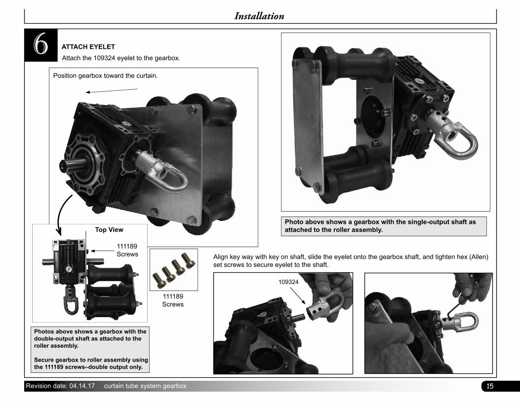
Align key way with key on shaft, slide the eyelet onto the gearbox shaft, and tighten hex (Allen) set screws to secure eyelet to the shaft.
109324
6Attach the 109324 eyelet to the gearbox.ATTACH EYELET
Installation
Photo above shows a gearbox with the single-output shaft as attached to the roller assembly.
Photos above shows a gearbox with the double-output shaft as attached to the roller assembly.
Secure gearbox to roller assembly using the 111189 screws–double output only.
Top View
Position gearbox toward the curtain.
111189 Screws
111189 Screws
16 curtain tube system gearbox Revision date: 04.14.17
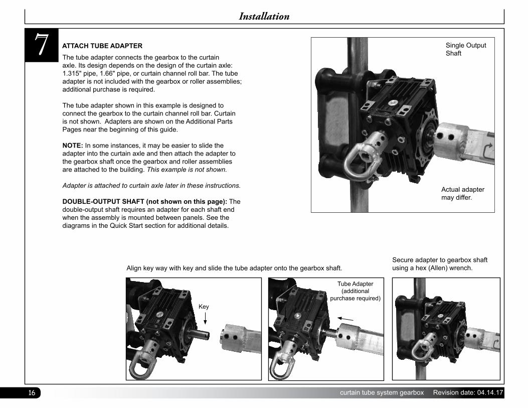
7The tube adapter connects the gearbox to the curtain axle. Its design depends on the design of the curtain axle: 1.315" pipe, 1.66" pipe, or curtain channel roll bar. The tube adapter is not included with the gearbox or roller assemblies; additional purchase is required.
The tube adapter shown in this example is designed to connect the gearbox to the curtain channel roll bar. Curtain is not shown. Adapters are shown on the Additional Parts Pages near the beginning of this guide.
NOTE: In some instances, it may be easier to slide the adapter into the curtain axle and then attach the adapter to the gearbox shaft once the gearbox and roller assemblies are attached to the building. This example is not shown.
Adapter is attached to curtain axle later in these instructions.
DOUBLE-OUTPUT SHAFT (not shown on this page): The double-output shaft requires an adapter for each shaft end when the assembly is mounted between panels. See the diagrams in the Quick Start section for additional details.
ATTACH TUBE ADAPTER
Align key way with key and slide the tube adapter onto the gearbox shaft.Secure adapter to gearbox shaft using a hex (Allen) wrench.
Tube Adapter (additional
purchase required)Key
Installation
Actual adapter may differ.
Single Output Shaft
17Revision date: 04.14.17 curtain tube system gearbox
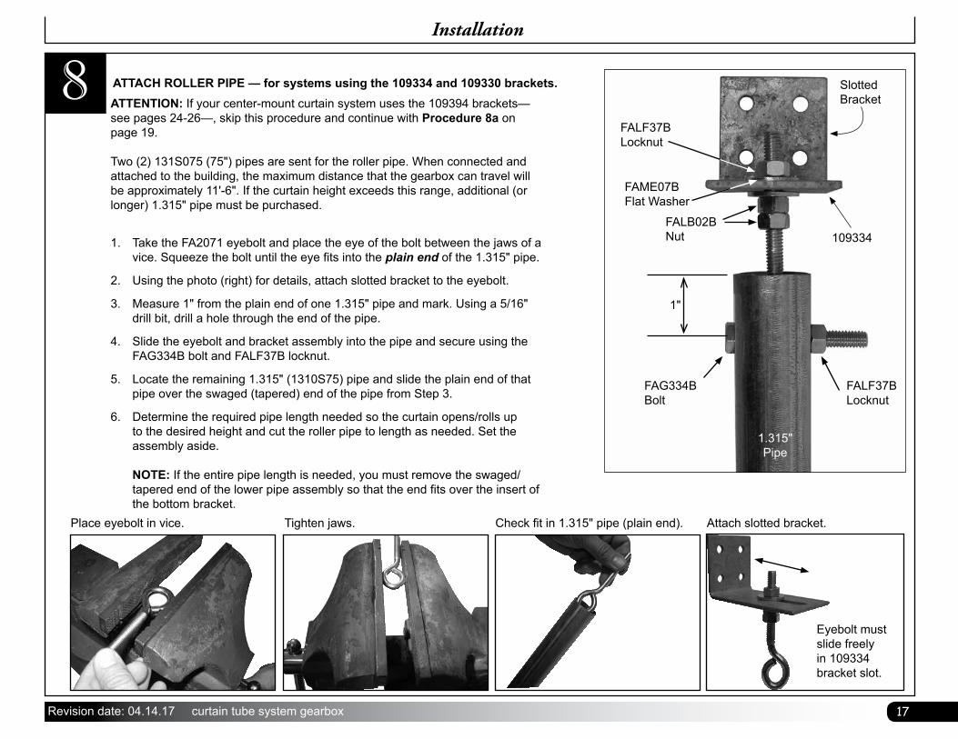
8 ATTENTION: If your center-mount curtain system uses the 109394 brackets—see pages 24-26—, skip this procedure and continue with Procedure 8a on page 19. Two (2) 131S075 (75") pipes are sent for the roller pipe. When connected and attached to the building, the maximum distance that the gearbox can travel will be approximately 11'-6". If the curtain height exceeds this range, additional (or longer) 1.315" pipe must be purchased.
1. Take the FA2071 eyebolt and place the eye of the bolt between the jaws of a vice. Squeeze the bolt until the eye fits into the plain end of the 1.315" pipe.
2. Using the photo (right) for details, attach slotted bracket to the eyebolt.
3. Measure 1" from the plain end of one 1.315" pipe and mark. Using a 5/16" drill bit, drill a hole through the end of the pipe.
4. Slide the eyebolt and bracket assembly into the pipe and secure using the FAG334B bolt and FALF37B locknut.
5. Locate the remaining 1.315" (1310S75) pipe and slide the plain end of that pipe over the swaged (tapered) end of the pipe from Step 3.
6. Determine the required pipe length needed so the curtain opens/rolls up to the desired height and cut the roller pipe to length as needed. Set the assembly aside. NOTE: If the entire pipe length is needed, you must remove the swaged/tapered end of the lower pipe assembly so that the end fits over the insert of the bottom bracket.
ATTACH ROLLER PIPE — for systems using the 109334 and 109330 brackets.
Place eyebolt in vice. Tighten jaws. Check fit in 1.315" pipe (plain end). Attach slotted bracket.
Eyebolt must slide freely in 109334 bracket slot.
Installation
Slotted Bracket
FALF37B Locknut
FALF37B Locknut
FAG334BBolt
1.315" Pipe
FAME07BFlat Washer
1"
FALB02BNut 109334
18 curtain tube system gearbox Revision date: 04.14.17
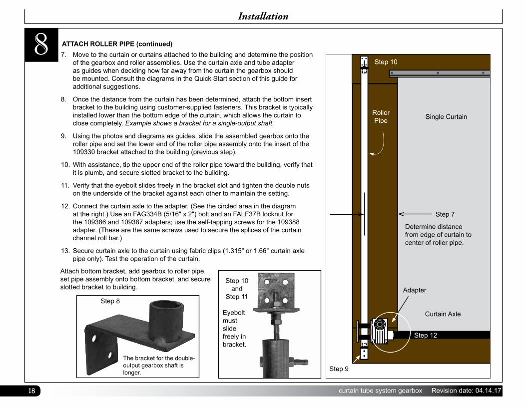
8 7. Move to the curtain or curtains attached to the building and determine the position of the gearbox and roller assemblies. Use the curtain axle and tube adapter as guides when deciding how far away from the curtain the gearbox should be mounted. Consult the diagrams in the Quick Start section of this guide for additional suggestions.
8. Once the distance from the curtain has been determined, attach the bottom insert bracket to the building using customer-supplied fasteners. This bracket is typically installed lower than the bottom edge of the curtain, which allows the curtain to close completely. Example shows a bracket for a single-output shaft.
9. Using the photos and diagrams as guides, slide the assembled gearbox onto the roller pipe and set the lower end of the roller pipe assembly onto the insert of the 109330 bracket attached to the building (previous step).
10. With assistance, tip the upper end of the roller pipe toward the building, verify that it is plumb, and secure slotted bracket to the building.
11. Verify that the eyebolt slides freely in the bracket slot and tighten the double nuts on the underside of the bracket against each other to maintain the setting.
12. Connect the curtain axle to the adapter. (See the circled area in the diagram at the right.) Use an FAG334B (5/16" x 2") bolt and an FALF37B locknut for the 109386 and 109387 adapters; use the self-tapping screws for the 109388 adapter. (These are the same screws used to secure the splices of the curtain channel roll bar.)
13. Secure curtain axle to the curtain using fabric clips (1.315" or 1.66" curtain axle pipe only). Test the operation of the curtain.
ATTACH ROLLER PIPE (continued)
Attach bottom bracket, add gearbox to roller pipe, set pipe assembly onto bottom bracket, and secure slotted bracket to building.
Step 8
The bracket for the double-output gearbox shaft is longer.
Installation
Step 10 and
Step 11
Eyebolt must slide freely in bracket.
Single Curtain
Step 7
Determine distance from edge of curtain to center of roller pipe.
Curtain Axle
Adapter
Step 12
Step 9
Step 10
Roller Pipe
19Revision date: 04.14.17 curtain tube system gearbox
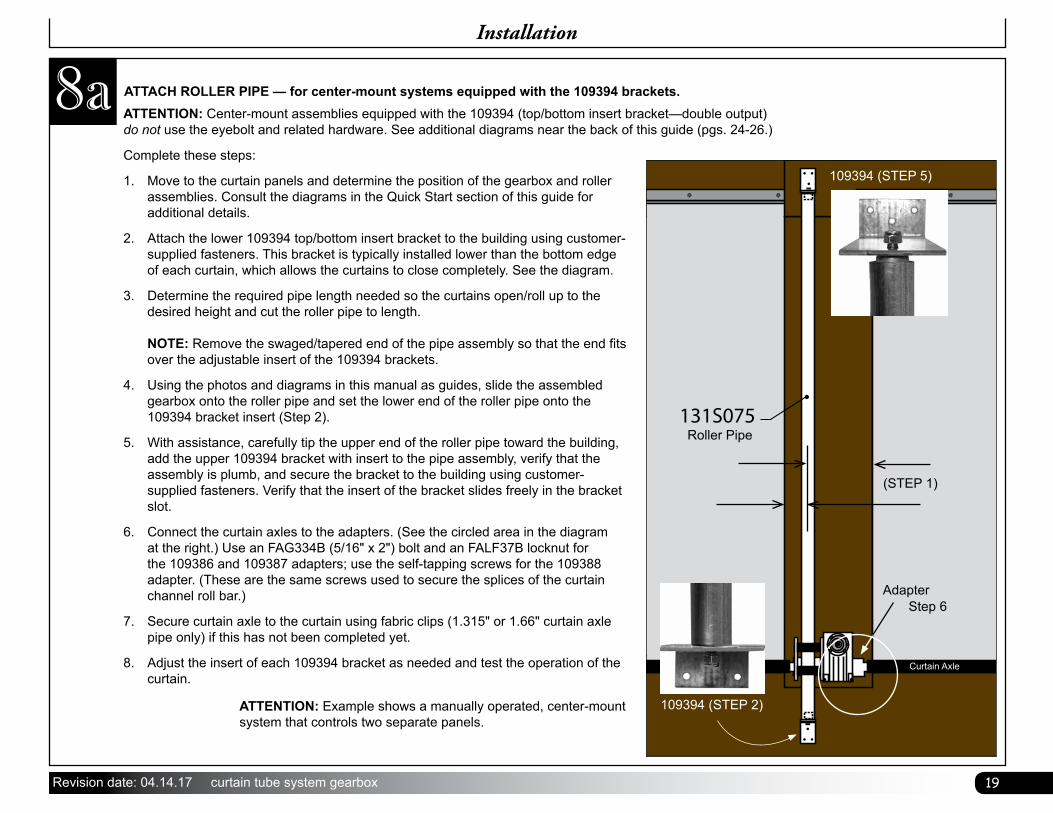
ATTACH ROLLER PIPE — for center-mount systems equipped with the 109394 brackets.8aInstallation
Complete these steps:
1. Move to the curtain panels and determine the position of the gearbox and roller assemblies. Consult the diagrams in the Quick Start section of this guide for additional details.
2. Attach the lower 109394 top/bottom insert bracket to the building using customer-supplied fasteners. This bracket is typically installed lower than the bottom edge of each curtain, which allows the curtains to close completely. See the diagram.
3. Determine the required pipe length needed so the curtains open/roll up to the desired height and cut the roller pipe to length. NOTE: Remove the swaged/tapered end of the pipe assembly so that the end fits over the adjustable insert of the 109394 brackets.
4. Using the photos and diagrams in this manual as guides, slide the assembled gearbox onto the roller pipe and set the lower end of the roller pipe onto the 109394 bracket insert (Step 2).
5. With assistance, carefully tip the upper end of the roller pipe toward the building, add the upper 109394 bracket with insert to the pipe assembly, verify that the assembly is plumb, and secure the bracket to the building using customer-supplied fasteners. Verify that the insert of the bracket slides freely in the bracket slot.
6. Connect the curtain axles to the adapters. (See the circled area in the diagram at the right.) Use an FAG334B (5/16" x 2") bolt and an FALF37B locknut for the 109386 and 109387 adapters; use the self-tapping screws for the 109388 adapter. (These are the same screws used to secure the splices of the curtain channel roll bar.)
7. Secure curtain axle to the curtain using fabric clips (1.315" or 1.66" curtain axle pipe only) if this has not been completed yet.
8. Adjust the insert of each 109394 bracket as needed and test the operation of the curtain.
ATTENTION: Center-mount assemblies equipped with the 109394 (top/bottom insert bracket—double output) do not use the eyebolt and related hardware. See additional diagrams near the back of this guide (pgs. 24-26.)
ATTENTION: Example shows a manually operated, center-mount system that controls two separate panels.
131S075
(STEP 1)
109394 (STEP 5)
Roller Pipe
AdapterStep 6
109394 (STEP 2)
Curtain Axle
20 curtain tube system gearbox Revision date: 04.14.17
Quick Start Guide
Quick Start Guide
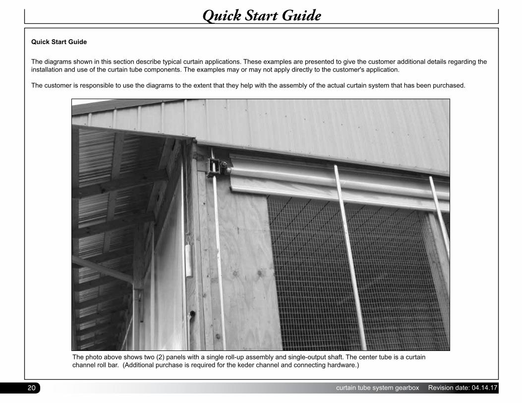
The diagrams shown in this section describe typical curtain applications. These examples are presented to give the customer additional details regarding the installation and use of the curtain tube components. The examples may or may not apply directly to the customer's application.
The customer is responsible to use the diagrams to the extent that they help with the assembly of the actual curtain system that has been purchased.
The photo above shows two (2) panels with a single roll-up assembly and single-output shaft. The center tube is a curtain channel roll bar. (Additional purchase is required for the keder channel and connecting hardware.)
21Revision date: 04.14.17 curtain tube system gearbox
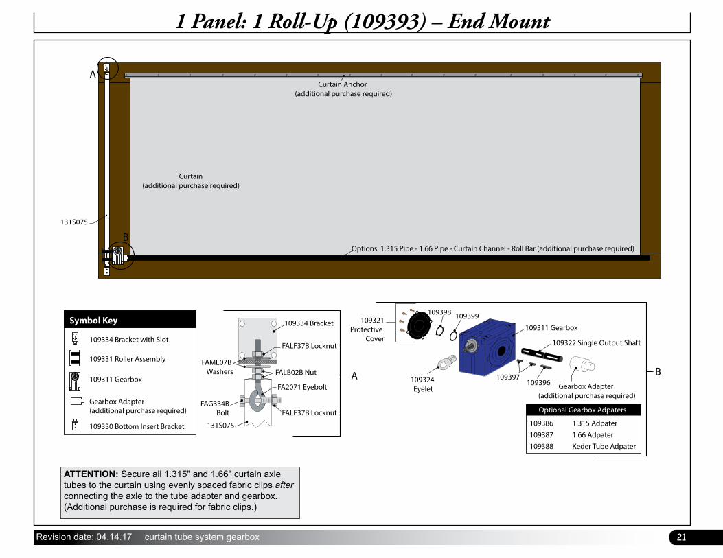
Curtain Anchor (additional purchase required)
Curtain(additional purchase required)
Options: 1.315 Pipe - 1.66 Pipe - Curtain Channel - Roll Bar (additional purchase required)
131S075
A
B
A
FALF37B Locknut
FALF37B Locknut
FA2071 Eyebolt
FALB02B NutFAME07B
Washers
FAG334BBolt
131S075
109334 BracketSymbol Key
109330 Bottom Insert Bracket
109334 Bracket with Slot
109331 Roller Assembly
Gearbox Adapter (additional purchase required)
109311 GearboxGearbox Adapter
(additional purchase required)
109311 Gearbox
109322 Single Output Shaft
109397109396
109398 109399
109324 Eyelet
109321Protective
Cover
Optional Gearbox Adpaters
109386 1.315 Adpater109387 1.66 Adpater109388 Keder Tube Adpater
B
1 Panel: 1 Roll-Up (109393) – End Mount
ATTENTION: Secure all 1.315" and 1.66" curtain axle tubes to the curtain using evenly spaced fabric clips after connecting the axle to the tube adapter and gearbox. (Additional purchase is required for fabric clips.)
22 curtain tube system gearbox Revision date: 04.14.17
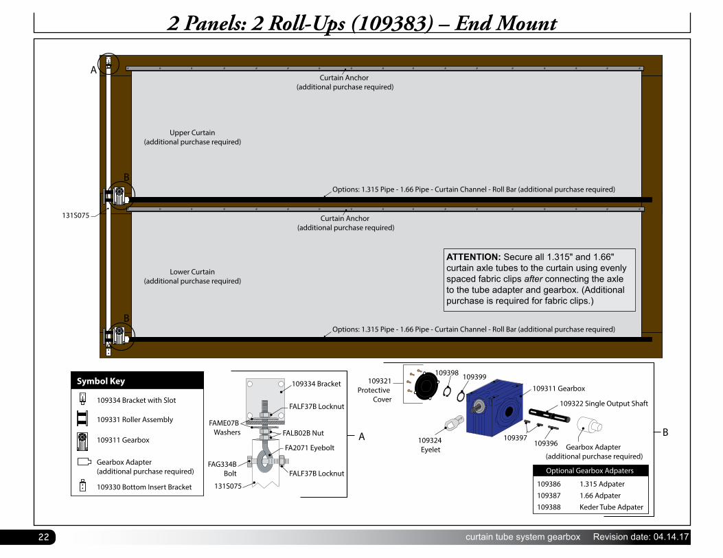
2 Panels: 2 Roll-Ups (109383) – End Mount
Upper Curtain(additional purchase required)
131S075
Lower Curtain(additional purchase required)
Curtain Anchor (additional purchase required)
A
B
B
Options: 1.315 Pipe - 1.66 Pipe - Curtain Channel - Roll Bar (additional purchase required)
Options: 1.315 Pipe - 1.66 Pipe - Curtain Channel - Roll Bar (additional purchase required)
Curtain Anchor (additional purchase required)
A
FALF37B Locknut
FALF37B Locknut
FA2071 Eyebolt
FALB02B NutFAME07B
Washers
FAG334BBolt
131S075
109334 BracketSymbol Key
109330 Bottom Insert Bracket
109334 Bracket with Slot
109331 Roller Assembly
Gearbox Adapter (additional purchase required)
109311 GearboxGearbox Adapter
(additional purchase required)
109311 Gearbox
109322 Single Output Shaft
109397109396
109398 109399
109324 Eyelet
109321Protective
Cover
Optional Gearbox Adpaters
109386 1.315 Adpater109387 1.66 Adpater109388 Keder Tube Adpater
B
ATTENTION: Secure all 1.315" and 1.66" curtain axle tubes to the curtain using evenly spaced fabric clips after connecting the axle to the tube adapter and gearbox. (Additional purchase is required for fabric clips.)
23Revision date: 04.14.17 curtain tube system gearbox
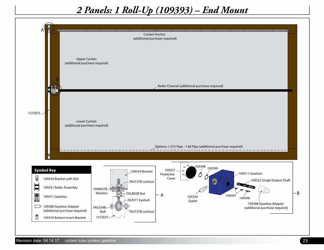
2 Panels: 1 Roll-Up (109393) – End Mount
Upper Curtain(additional purchase required)
131S075
Curtain Anchor (additional purchase required)
Keder Channel (additional purchase required)
Lower Curtain(additional purchase required)
Options: 1.315 Pipe - 1.66 Pipe (additional purchase required)
A
B
A
FALF37B Locknut
FALF37B Locknut
FA2071 Eyebolt
FALB02B NutFAME07B
Washers
FAG334BBolt
131S075
109334 BracketSymbol Key
109330 Bottom Insert Bracket
109334 Bracket with Slot
109331 Roller Assembly
109388 Gearbox Adapter (additional purchase required)
109311 Gearbox
109388 Gearbox Adapter (additional purchase required)
109311 Gearbox
109322 Single Output Shaft
109397109396
109398 109399
109324 Eyelet
109321Protective
Cover
B
24 curtain tube system gearbox Revision date: 04.14.17
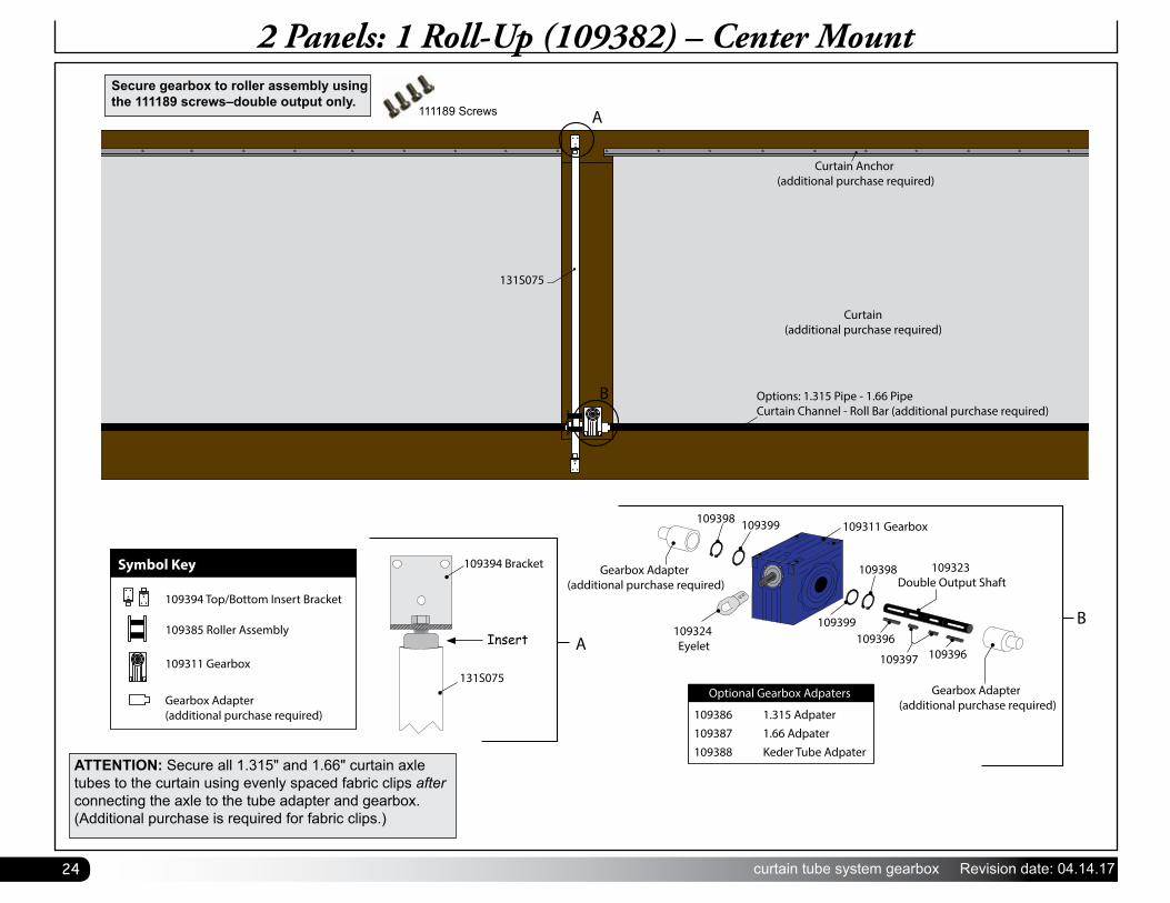
2 Panels: 1 Roll-Up (109382) – Center Mount
Gearbox Adapter (additional purchase required)
Gearbox Adapter (additional purchase required)
109311 Gearbox
109324 Eyelet
B109399
109398
109398 109399
109323 Double Output Shaft
109397 109396109396
Curtain Anchor (additional purchase required)
Curtain(additional purchase required)
Options: 1.315 Pipe - 1.66 Pipe Curtain Channel - Roll Bar (additional purchase required)
A
131S075
B
Optional Gearbox Adpaters
109386 1.315 Adpater109387 1.66 Adpater109388 Keder Tube Adpater
A
Symbol Key
Gearbox Adapter (additional purchase required)
131S075
109394 Bracket
109394 Top/Bottom Insert Bracket
109385 Roller Assembly
109311 Gearbox
ATTENTION: Secure all 1.315" and 1.66" curtain axle tubes to the curtain using evenly spaced fabric clips after connecting the axle to the tube adapter and gearbox. (Additional purchase is required for fabric clips.)
Secure gearbox to roller assembly using the 111189 screws–double output only.
111189 Screws
Insert
25Revision date: 04.14.17 curtain tube system gearbox
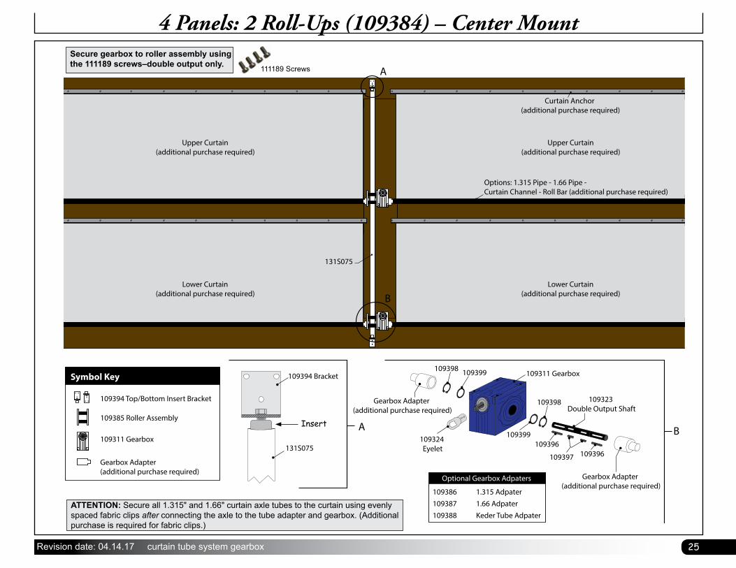
4 Panels: 2 Roll-Ups (109384) – Center Mount
Upper Curtain(additional purchase required)
Lower Curtain(additional purchase required)
A
B
Options: 1.315 Pipe - 1.66 Pipe - Curtain Channel - Roll Bar (additional purchase required)
Curtain Anchor (additional purchase required)
131S075
Upper Curtain(additional purchase required)
Lower Curtain(additional purchase required)
Gearbox Adapter (additional purchase required)
Gearbox Adapter (additional purchase required)
109311 Gearbox
109324 Eyelet
B
109398
109399
109398 109399
109323 Double Output Shaft
109397 109396109396
Optional Gearbox Adpaters
109386 1.315 Adpater109387 1.66 Adpater109388 Keder Tube Adpater
A
Symbol Key
Gearbox Adapter (additional purchase required)
131S075
109394 Bracket
109394 Top/Bottom Insert Bracket
109385 Roller Assembly
109311 Gearbox
ATTENTION: Secure all 1.315" and 1.66" curtain axle tubes to the curtain using evenly spaced fabric clips after connecting the axle to the tube adapter and gearbox. (Additional purchase is required for fabric clips.)
Secure gearbox to roller assembly using the 111189 screws–double output only. 111189 Screws
Insert
26 curtain tube system gearbox Revision date: 04.14.17
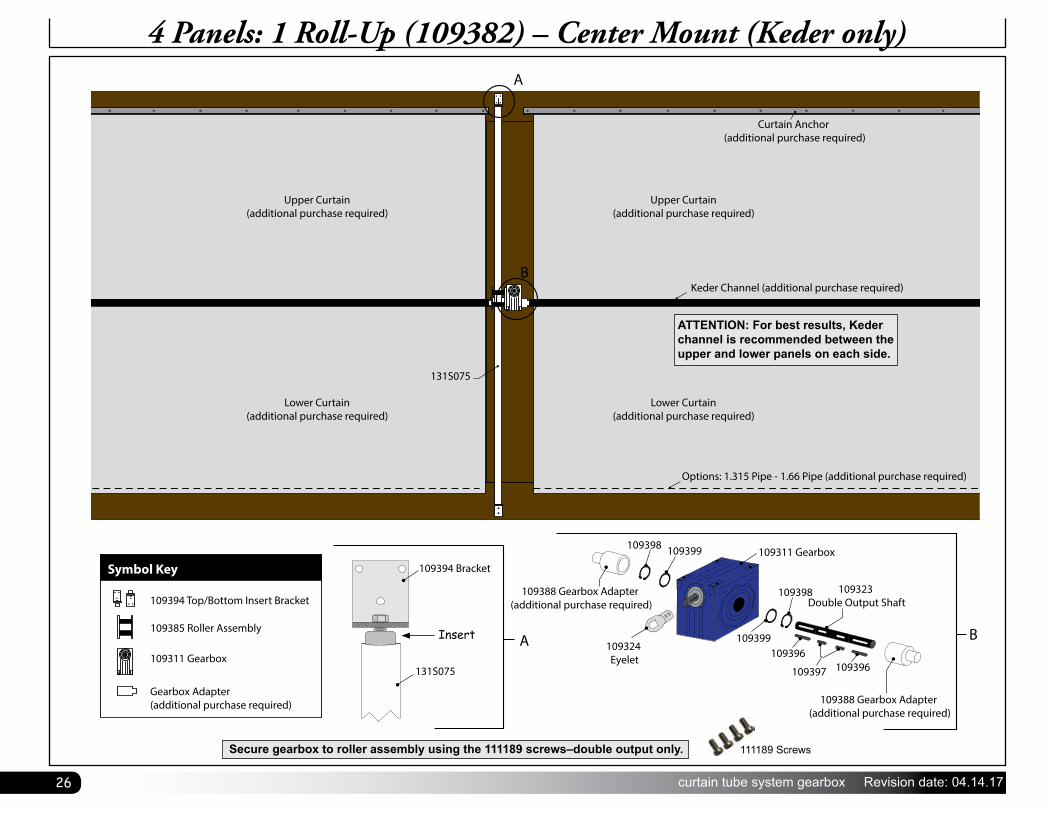
4 Panels: 1 Roll-Up (109382) – Center Mount (Keder only)
Upper Curtain(additional purchase required)
Lower Curtain(additional purchase required)
Upper Curtain(additional purchase required)
Curtain Anchor (additional purchase required)
Keder Channel (additional purchase required)
Lower Curtain(additional purchase required)
Options: 1.315 Pipe - 1.66 Pipe (additional purchase required)
A
131S075
A
109388 Gearbox Adapter (additional purchase required)
109388 Gearbox Adapter (additional purchase required)
109311 Gearbox
109324 Eyelet
B
B
109398
109398 109399
109323 Double Output Shaft
109397 109396109396
109399
Symbol Key
Gearbox Adapter (additional purchase required)
131S075
109394 Bracket
109394 Top/Bottom Insert Bracket
109385 Roller Assembly
109311 Gearbox
ATTENTION: For best results, Keder channel is recommended between the upper and lower panels on each side.
Secure gearbox to roller assembly using the 111189 screws–double output only. 111189 Screws
Insert

27Revision date: 04.14.17 curtain tube system gearbox
Page Reserved For Customer Notes