Embed Size (px)
Citation preview

April-04 N7VE / Ozarkcon Class E PresentationCopyright 1994, All rights reserved
Class E AmplifiersPart 1: Class E Basics
Dan Tayloe, N7VE

April-04 N7VE / Ozarkcon Class E PresentationCopyright 1994, All rights reserved
5w Class E 40m Prototype
Power Amp
6v Regulator
Output Network
50 ohm Load
“Straight Key”
April-04 N7VE / Ozarkcon Class E PresentationCopyright 1994, All rights reserved
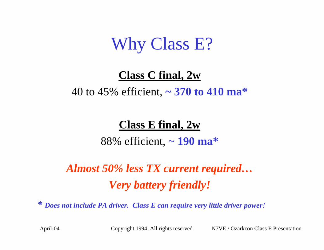
Why Class E?Class C final, 2w
40 to 45% efficient, ~ 370 to 410 ma*
Class E final, 2w88% efficient, ~ 190 ma*
Almost 50% less TX current required…Very battery friendly!
* Does not include PA driver. Class E can require very little driver power!

April-04 N7VE / Ozarkcon Class E PresentationCopyright 1994, All rights reserved
Class E Efficiency Secret
Voltage vs. time
Current vs. time
Taken from QEX Jan/Feb 2001
Switch at low current,Low voltage points~Zero power at switch!
April-04 N7VE / Ozarkcon Class E PresentationCopyright 1994, All rights reserved
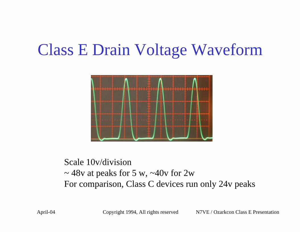
Class E Drain Voltage Waveform
Scale 10v/division ~ 48v at peaks for 5 w, ~40v for 2wFor comparison, Class C devices run only 24v peaks

April-04 N7VE / Ozarkcon Class E PresentationCopyright 1994, All rights reserved
Class E Design Spread Sheet, 7 MHzQEX Jan/Feb 2001 Class E Design Equations
High EfficiencyAt 7 MHz
Use Q and exact Power to get C1, L2, C2 to standard values

April-04 N7VE / Ozarkcon Class E PresentationCopyright 1994, All rights reserved
Class E Design Spread Sheet, 14 MHzQEX Jan/Feb 2001 Class E Design Equations
Reduced EfficiencyAt 14 MHz
Lower efficiency at 14 MHz – 69% Predicted

April-04 N7VE / Ozarkcon Class E PresentationCopyright 1994, All rights reserved
Class E Design Spread SheetExcel spread sheet equations…
C1 (pf) = (1e12/(J8*34.2219*D8))*(0.99866 + 0.91424/(E8) -1.03175/(E8*E8)) + 0.6/(2*2*3.14*3.14*D8*D8*G8/1000000)
C2 (pf) = (1e12/(J8*2*3.14*D8))*(1/(E8-0.104823))*(1.00121 + 1.01468/(E8 - 1.7879)) -0.2/(2*2*3.14*3.14*D8*D8*G8/1000000)
L1 (uH) = 1000000*L8/(2*3.14*D8)
L2 (uH) = 1000000*J8*E8/(2*3.14*D8)
Rload = (C8*C8/B8)*0.576801*(1.001245 - 0.451759/E8 - 0.402444/(E8*E8))
XL1 >= 30*K8
Efficiency = J8/(J8+1.365*K27) -0.01 - (1+ 0.82/E8)* (1+ 0.82/E8)*4*PI()*PI()*D8*D8*L27*L27*1e-18/12

April-04 N7VE / Ozarkcon Class E PresentationCopyright 1994, All rights reserved
Class E AmplifiersPart 2: No Tune, Goof Proof Class E Amps
Dan Tayloe, N7VE

April-04 N7VE / Ozarkcon Class E PresentationCopyright 1994, All rights reserved
Problems with Class E QRP Amps • “Tuning” required to get good efficiency
• Poor “out of the box” power and efficency • Typical to “tweak” output network coils for best power/efficiency
• Class E finals fail when presented with low impedance loads• Low impedance loads cause PA to draw too much current and burn up
• Inexpensive QRP Class E final rated to only 60v (2N7000)• Typical PA drain voltage operates in the 40 to 50v range w/ 12v supply• Improper antenna mismatch can raise drain voltage, blow the PA
• 15v supply used with a 12v design could cause problems
• Class E Amps can be unstable into poorly matched loads• Tends to “take off”• Can lead to device failure
April-04 N7VE / Ozarkcon Class E PresentationCopyright 1994, All rights reserved
Class E Tuning Problem• Class E matching network typically presents a reactive load
• I.e., the Class E PA output impedance is not purely resistive• Reactive characteristic key to Class E efficiency
• QRP Class E networks need loads in the 10 ohm to 50 ohm (5w to 1w) range
• Matching network normally needed to transform to 50 ohm load• 1 watt 12v final is a design “sweet spot” – no matching needed
• L/C matching networks are typically used to transform driver impedance to 50 ohm load impedance.
• This approach does not work well with a reactive drive source!• Leads to frequency specific matching network• Variations in driver network and matching network elements force the need for “tuning” of the matching networks

April-04 N7VE / Ozarkcon Class E PresentationCopyright 1994, All rights reserved
No Tune Class E Solution: Use a broadband matching transformer!
• Broadband Transformer matches 20 ohm PA output to 50 ohm LPF• Transformer converts Class E reactive impedance without being frequency selective• However, efficiency is lower (~60%) as measured on 20 & 30m
Tx 50 ohmLow Pass Filter
BroadbandMatching XFMR
18 to 50 ohm
Class Enetwork

April-04 N7VE / Ozarkcon Class E PresentationCopyright 1994, All rights reserved
Class E Load InstabilitySolution: Use a lower impedance gate driver!
• AC family has 24 ma of drive vs 8 ma for HC family• Higher current drive = lower drive source impedance• 3x lower source impedance reduces tendency to “flight” with mismatched load• PA gate biased on TX to 3v to help MOSFET turn on harder
3v Tx Gate Bias High Current
Drive Part

April-04 N7VE / Ozarkcon Class E PresentationCopyright 1994, All rights reserved
Class E Driver – 74ACT00
Scale: Vertical 2v/div, Horizontal 20 nsec/div6 to 8v at peaksVery fast rise+fall times: ~10 nsec total
74ACT00 has 24 ma of drive vs. only 8 ma for the more common 74HCT00 parts

April-04 N7VE / Ozarkcon Class E PresentationCopyright 1994, All rights reserved
Class E Voltage LimitationsReduce output when drain voltage gets too high!
• Monitor PA RF drain voltage peaks• If voltage gets higher than 55v, comparator triggers bias clamp• Reducing TX gate bias voltage reduces output power to safe limits
Over-voltageComparator
RF VoltagePeak Detector
TX DriveBias Clamp
April-04 N7VE / Ozarkcon Class E PresentationCopyright 1994, All rights reserved
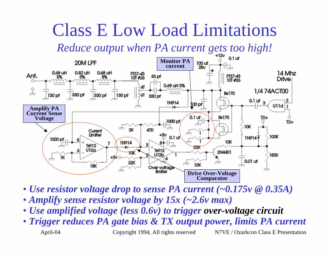
Class E Low Load LimitationsReduce output when PA current gets too high!
• Use resistor voltage drop to sense PA current (~0.175v @ 0.35A)• Amplify sense resistor voltage by 15x (~2.6v max)• Use amplified voltage (less 0.6v) to trigger over-voltage circuit• Trigger reduces PA gate bias & TX output power, limits PA current
Monitor PAcurrent
Amplify PACurrent Sense
Voltage
Drive Over-VoltageComparator

April-04 N7VE / Ozarkcon Class E PresentationCopyright 1994, All rights reserved
No Tune, Goof Proof, Class E Tx
• High impedance over-voltage protection• Low impedance over-current protection• “No Tune” Class E output

April-04 N7VE / Ozarkcon Class E PresentationCopyright 1994, All rights reserved
Current Class E Limitations• Efficiency of common QRP PA devices (2N7000, BS170) drops off at 14 MHz and above
- ~80 to 90% efficiency at 10 MHz and below- ~70% efficiency at 14 MHz- ~60 % efficiency using “no tune” approach shown here- R/C freq response: Smaller Driver R = Higher Freq response
- Higher PA drive power can be used to get higher freq PA response- Higher PA drive power hurts overall transmitter power saving
• Higher frequency devices available, but more expensive- Example: STMicroelectronics PD57006s 900 MHz 5w FET, ~$12

April-04 N7VE / Ozarkcon Class E PresentationCopyright 1994, All rights reserved
Current Class E Limitations, cont
• Class E operates at a fixed power set by Class E output network
• Variable power best done by changing supply voltage
• May be able to reduce power from preset maximum by lowering TX gate drive bias, but at reduced TX efficiency.

April-04 N7VE / Ozarkcon Class E PresentationCopyright 1994, All rights reserved
Transmitter Spectrum
Scale 10 db/division – legal limit 30 db down2nd Harmonic ~45 db down3rd Harmonic ~47 db down
All other more than 70 db down
14 MHz fund2nd Harmonic
3rd Harmonic

April-04 N7VE / Ozarkcon Class E PresentationCopyright 1994, All rights reserved
Class E Amplifiers
Part 3: Good & Bad QRP Class E DevicesOr
“Bigger is not Better”
Dan Tayloe, N7VE
April-04 N7VE / Ozarkcon Class E PresentationCopyright 1994, All rights reserved
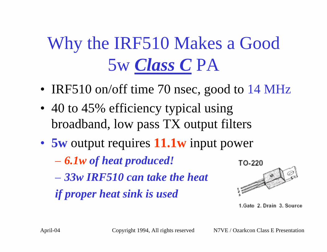
Why the IRF510 Makes a Good 5w Class C PA
• IRF510 on/off time 70 nsec, good to 14 MHz• 40 to 45% efficiency typical using
broadband, low pass TX output filters• 5w output requires 11.1w input power
– 6.1w of heat produced!– 33w IRF510 can take the heatif proper heat sink is used

April-04 N7VE / Ozarkcon Class E PresentationCopyright 1994, All rights reserved
Why the 2N7000 makes a goodQRP Class E final
and the IRF510 does not

April-04 N7VE / Ozarkcon Class E PresentationCopyright 1994, All rights reserved
Good FET – 2N7000, 0.3 to 0.6w
Low input C: 25 pf typical – Low input drive drive!Fast Turn on/off time: 3+12 nsec = 15 nsec
For class E, need On/Off to be 30% of ½ RF cycle (QEX 1/01)• Gives maximum limit of 10 MHz for full efficiency• Can be used at 14 MHz at reduced efficiency
• Measured 80-90% at 7 & 10 MHz, 70% at 14 MHz

April-04 N7VE / Ozarkcon Class E PresentationCopyright 1994, All rights reserved
Difficult FET – IRF510, 33w
Higher input C: 190 pf typical – Higher input drive needed!• Specs use 24 ohm source here vs. 50 ohm source for 2N7000
Slower Turn on/off time: 10+14+28+18 nsec = 70 nsec
For class E, need On/Off to be 30% of ½ RF cycle• Gives maximum limit of 2 MHz for full efficiency• Can speed up by using a lower impedance drive source.
• Slam it on, slam it off! – more drive power needed.Double driver power hit: High input C & Slow switching time

April-04 N7VE / Ozarkcon Class E PresentationCopyright 1994, All rights reserved
Class E Driver RequirementsIRF510 vs. 2N7000
• IRF510, 190 pf input gate C; 2N7000, 25 pf – Drive power factor of 7.6x
• IRF510, 25 ohm source; 2n7000, 50 ohm source– Drive power factor of 2x
• IRF510, 70 nsec turn on/off; 2n7000, 15 nsec– Need 4.67x lower drive impedance to get same speed
• IRF510 requires 5 ohm driver impedance for 15 nsec on/off
Total drive difference: IRF510 needs 71x more drive power than a single 2N7000
~ 0.6w drive for class E IRF511 vs. 17mW for a pair of 2N7000s
IRF510: Good 100w Class E amp, poor 5w amp!

April-04 N7VE / Ozarkcon Class E PresentationCopyright 1994, All rights reserved
• Class E saves ~ 50% on TX DC input power to PA– Low drive power (17 mW vs. 0.6w) saves additional power
• Class C requires large TO220 PA transistors• Class E needs only tiny T092/SOT23 300mw/600mw
packages• $0.14 for a new pair of Class E QRP finals!• Low wasted TX pwr (Heat)
– For 5w output, 0.5 to 1w heat (class E) vs. 5 to 6w heat!– Conserves battery life (smaller battery?)– Reduces VFO drift
Conclusions

April-04 N7VE / Ozarkcon Class E PresentationCopyright 1994, All rights reserved
Class E Summary• Class E can give up to 88% efficiency
– But require tuning to get proper power output
• Protection circuitry available for Class E finals– Protects against antenna open/short/mismatch problems
• “No Tune” Class E works, but ~60% efficiently• Bigger is not better for Class E finals
– High power MOSFETs (such as the IRF511) require high drive power (71x!), reducing overall rig efficiency.