Embed Size (px)
Citation preview

CIVIL GEOTECHNICAL SERVICES
ABN 26 474 013 724 PO Box 678 Croydon Vic 3136
Telephone: 9723 0744 Facsimile: 9723 0799
14370 : PJF1940/528 : October 2014
14 October 2014 Our Reference: 14370:PJF1940/528 Cranbourne Road Holdings c/- Villawood Properties Level 1 6 Riverside Quay SOUTHBANK VIC 3006 Dear Sirs,
RE: LOT 528 OF THE PASADENA ESTATE (STAGE 5), CLYDE
Winslow Constructors Pty Ltd has recently constructed a residential subdivision (referred to as Stage 5 of The Pasadena Estate) which is located on the west side of Clyde – Five Ways Road in Clyde. As part of the subdivisional works, Civil Geotechnical Services were engaged by Winslow Constructors to provide inspection and testing services for the bulk earthworks associated with the construction of the residential allotments. The testing and inspection services were undertaken in accordance with the Level 1 requirements of AS 3798 – Guidelines on Earthworks for Commercial and Residential Developments. Construction of the Lot noted above essentially involved a fill operation, with the estimated maximum depth of fill materials (excluding topsoil placement) being up to 1.1 metres in depth. However, there could be localised areas of slightly deeper fill materials arising from site stripping and foundation preparation works. The fill materials were spread and compacted in 0.2 to 0.3 metre (solid) lifts using a vibrating pad foot roller and/or compactor. The fill materials essentially comprised clays that were sourced from adjacent stages of the Pasadena Estate. Compaction testing of these materials was performed at regular intervals (both vertically and laterally) during fill placement. The resulting density ratios were all in excess of 95% (standard compactive effort). A copy of the Level 1 report is attached. The Cranbourne sheet of the Geological Survey Maps of Victoria shows the above site to be underlain by Tertiary aged deposits associated with the Baxter formation. These latter materials essentially comprise high plasticity clays that exhibit moderate to high shrink-swell surface movements when subjected to changes in seasonal soil moisture content. The anticipated geology and the foregoing description of the underlying materials were generally confirmed by site observations undertaken during construction of the subdivision (eg foundation preparation works, trench excavations etc). As a consequence of the site earthworks, the founding medium for a conventional shallow footing system will most likely comprise the compacted fill materials. As the depth of the compacted clayey fill materials is in excess of 0.4 metres, a Class P classification in accordance with Section 2 of AS 2870 – Residential Slabs and Footings would normally be appropriate. However, as the fill materials that have been placed during the recent phase of construction have been placed in a controlled manner, a less severe classification would, in appropriate circumstances, be applicable.

2
14370 : PJF1940/528 : October 2014
After a consideration of the foregoing, together with the depth of fill placed and the materials utilised as controlled fill, the site has been reclassified as CLASS H2. Accordingly, a conventional shallow footing system that is founded in the ‘undisturbed’ fill materials could be satisfactorily utilised at this allotment. The most appropriate foundation system for this allotment is a conventional stiffened raft slab founding in the controlled fill materials. Accordingly, it is recommended that a stiffened raft slab be utilised, with the slab designed and detailed in accordance with the Class H2 classification requirements of AS 2870. The edge and load bearing beams should be founded in the ‘undisturbed’ compacted clayey fill materials at a minimum depth of 0.5 metres below finished surface levels. Edge and load bearing beams founding in this manner would have an allowable bearing pressure of 100 kPa. The raft stiffening beams, provided that their contact pressures do not exceed 50 kPa, should be founded in the ‘undisturbed’ fill materials at a minimum depth of 0.2 metres below finished surface levels. The slab infill panels can be founded directly onto the ‘undisturbed’ compacted fill materials. Consideration could also be given to utilising a waffle raft slab. However, if a waffle raft slab is utilised, the near surface topsoil and any loose and disturbed materials will need to be removed from the building footprint prior to construction. Previous experience suggests that this option will require the removal of up to 0.25 metres of topsoil materials and the like. However, there may be sections of the site where additional excavation depths are required. If a waffle raft slab is to be utilised, the waffle raft slab should be designed and detailed in accordance with the Class H2 classification requirements of AS 2870. Particular attention will also need to be directed towards ensuring that a stable moisture regime is maintained around the slab periphery. Furthermore, due to the significant problems that have been experienced with washout from the undersides of slab edges and corners, it will be necessary to found the perimeter beams into the ‘undisturbed’ compacted clayey fill materials for a distance of not less than 0.4 metres. Perimeter beams founding in this manner would have an allowable bearing pressure of 100 kPa. Internal beams may be founded in the ’undisturbed’ compacted clayey fill materials at higher levels than the perimeter beams. An allowable bearing pressure of 100 kPa is also available for these latter beams. The site classifications and design recommendations presented above assume that the current natural drainage and infiltration conditions at the site will not be markedly affected by the proposed site development work. Care should therefore be taken to ensure that surface water is not permitted to collect adjacent to any structure and that significant changes to seasonal soil moisture equilibria do not develop as a result of service trench construction, garden bed development or tree root action. Attention is drawn to Appendix B of AS 2870 and its referenced documents as a guide to maintenance requirements for any proposed structures. In particular, attention should be directed at the design stage towards ensuring that any structures are relatively flexible and well articulated (eg closely spaced full height articulation joints, minimal brickwork over or under widow openings etc). Guidance on articulation spacings and associated detailing are provided in Technical Note 61 - Articulated Walling which is published by The Cement and Concrete Association of Australia. The base of all footing trenches should be carefully inspected to ensure that a satisfactory founding medium is achieved. If any doubt exists to the suitability or otherwise of the founding medium, this office should be consulted immediately. Civil Geotechnical Services Peter Fry Attachment: Level 1 report dated 6 October 2014 – Our Reference: 11145:PJF1939
CIVIL GEOTECHNICAL SERVICES ABN 26 474 013 724
PO Box 678 Croydon Vic 3136
Telephone: 9723 0744 Facsimile: 9723 0799
11145 : PJF1939 : October 2014
6 October 2014 Our Reference: 11145:PJF1939 Cranbourne Road Holdings c/- Villawood Properties Level 1 6 Riverside Quay SOUTHBANK VIC 3006 Dear Sirs,
RE: LEVEL 1 EARTHWORKS INSPECTION AND TESTING PASADENA ESTATE, CLYDE – STAGE 5
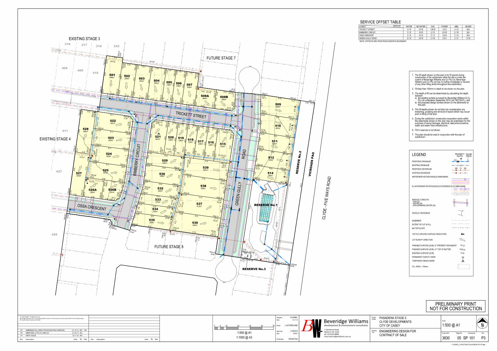
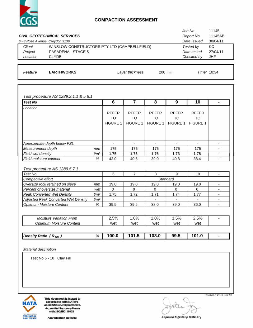
Please find attached our Report Nos 11145AA to 11145AH, 11189AA and 11189AB and 11370AA to 11370AJ that relate to the field density testing that was conducted within the filled allotments associated with the construction of Stage 5 of the above subdivision (refer also to the attached drawing). The site stripping and associated filling works within this stage of the estate commenced in early April 2011 and continued on an ad hoc basis until mid to late October 2011. The inspection and testing duties, which were performed by experienced geotechnical engineers and geotechnicians from this office, were undertaken in accordance with the Level 1 guidelines presented in AS 3798 - Guidelines on earthworks for commercial and residential developments. The testing was performed to the relevant Australian Standards and the accompanying test reports carry NATA endorsement. Prior to fill placement, the stripped surfaces were inspected to ensure that a firm foundation free of organic matter and the like was achieved. Any soft spots and unstable areas and the like that were encountered were removed down to a firm base and replaced with suitably compacted clays. The fill materials during the recent construction phase were initially spread by a track mounted dozer and then compacted in 0.3 to 0.35 metre (loose) lifts using both a heavy vibrating pad foot roller and a compactor. The fill materials essentially comprised high plasticity clays that were sourced from adjacent stages. Compaction testing of these materials was performed at regular intervals (both vertically and laterally) to confirm that the method of fill placement was appropriate. Any areas that were deemed unsatisfactory were re-worked or given extra rolling to ensure that the compaction criteria was met. The purpose of performing Level 1 inspection and testing duties is to ensure the quality of the as constructed fill pad(s) and to both minimise the costs of extensive testing and eliminate any unnecessary time delays arising from the testing process. Hence, the provision of Level 1 duties allows the contractor to undertake the filling operation whilst the testing authority monitors the quality control process of the operation. As part of this latter process, the testing authority monitors the compaction methodology on a visual basis and undertakes a number of randomly placed spot checks (ie field density and associated compaction tests) to confirm that the adopted methodology is appropriate.
2
11145 : PJF1939 : October 2014
The attached compaction results, which were located randomly throughout the depth and breadth of the filled areas, are considered to be representative of the bulk fill materials that were placed within the abovementioned stage by Winslow Constructors Pty Ltd during the aforementioned period (Winslow were contracted to undertake the bulk earthworks for Stage 5 of the Pasadena Estate). The density ratios were all in excess of 95% (standard compactive effort) and the corresponding moisture ratios varied 2.5% either side of optimum moisture. We are of the view that the bulk fill materials that have been placed within Stage 5 of the Pasadena Estate by Winslow Constructors during the aforementioned period can be considered as having been placed in a controlled manner to a minimum density ratio of 95% (standard compactive effort). Accordingly, the fill materials would be deemed to comply with both the controlled fill requirements of Clause 1.8.13 of AS 2870 – Residential slabs and footings and the structural fill requirements of Clause 1.2.13 of AS 3798. Please contact the undersigned if you require any additional information. Yours faithfully, Civil Geotechnical Services Peter Fry
42.09
42.23
42.31
43.66
44.60
44.40
44.84
44.28
42.46
41.53
41.27
42.46
41.13
39.96
41.15
41.80
39.78
41.19
42.08
42.08
41.90
42.15
41.83
41.87
41.76
41.68
41.57
41.56
41.22
41.55
40.87
41.06
40.63
42.08
43.05
44.36
42.60
43.77
42.34
42.81
45.49
46.73
44.93
44.48
44.07
40.05
41.02
39.40
41.32
39.4041.23
40.04
40.85
41.5940.51
42.04
45.12
44.20
47.71
40.28
41.07
41.46
41.99
41.83
39.40
41.20
41.75
40.77
41.50
41.08
40.66
40.64
42.13
40.07
42.14
41.06
42.06
43.60
41.81
43.18
41.76
42.77
42.00
42.29
42.26
42.16
41.74
41.67
41.46
41.86
42.34
41.15
41.61
42.37
40.35
40.35
41.78
42.23
41.64
41.92
41.90
43.29
43.86
44.10
41.67
42.49
FS44.35
FS44.32
FS43.75
FS43.66
FS44.60
FS44.51
FS44.90
FS44.93
FS44.09
FS43.34
FS42.36
FS42.32
FS42.32
FS39.96
FS41.15
FS42.61
FS42.62
FS43.17
FS43.59
FS44.36
FS44.38
FS43.61
FS44.26
FS43.47
FS44.05
FS43.30
FS43.92
FS43.19
FS43.78
FS43.07
FS42.93
FS42.91
FS42.71
FS43.38
FS43.87
FS44.22
FS43.68
FS44.02
FS43.45
FS43.60
FS44.46
FS44.55
FS44.46
FS44.21
FS44.80
FS42.53
FS41.77
FS42.48
FS41.73
FS42.39
FS41.69
FS42.32
FS41.68
FS42.26
FS41.70
FS43.70
FS44.32
FS44.12
FS44.60
FS41.70
FS41.83
FS43.20
FS43.35
FS43.45
FS42.31
FS43.08
FS43.28
FS42.97
FS43.21
FS43.15
FS42.86
FS43.07
FS42.75
FS43.02
FS42.67
FS41.85FS42.29
FS41.96
FS43.76
FS44.50
FS43.66
FS44.26
FS43.55
FS44.02
FS43.55
FS43.30
FS42.24
FS43.34
FS43.50
FS42.16
FS43.20
FS43.69
FS44.00
FS42.17
FS43.43
FS43.79
FS42.55
FS42.54
FS42.44
FS42.52
FS43.31
FS43.66
FS43.43
FS43.89
FS44.30
FS44.38
FS43.31
FS43.89
T42.71
T42.63
T42.56
T42.49
T42.42T43.11
T42.64
T42.56
T42.83
T42.84
T42.72
T44.14
44.87FS44.93
FS44.55
ND WATER
NOTE: OFFSETS ARE FROM ROAD RESERVE BOUNDARY
POWERSTREET SEWERWATERSERVICE GAS NBN
3.1 N 2.6 N 2.1 S1.85 N 2.6 S
3.1 E
3.1 S
3.1 W
2.6 E 2.1 W2.1 E 2.6 W N/A
2.6 S 2.1 N2.1 S 2.6 N N/A
2.6 W 2.1 E2.1 W 2.6 E
TRICKETT STREET
BIMBERRY CIRCUIT
OSSA CRESCENT
GREEN GULLY ROAD 1.0 W
N/A
N0 50403020105
NOT FOR CONSTRUCTIONPRELIMINARY PRINT
2m S E
3m D & S E
2m D E
2m S E2m S E
2m D E
3m S E
3m D & S E
3m S E
2m S E
SERVICE OFFSET TABLE
TRICKETT STREET
GR
EE
N G
ULLY
RO
AD
BIM
BE
RR
Y CIR
CUIT
OSSA CRESCENT
501 502503
504505 506
507
508A 508B
509
510
511
512
514
RESERVE No.1
515516517
518520521
522
523
524
525
526A 526B
528
529
530
532
533
534
14.0012.50
12.50
8.508.50
11.0116.49
32.00
32.00
14.00
28.00
28.00
28.00
28.00
28.00
28.00
28.00
12.5012.50
8.508.50
11.01
16.00
16.49
14.97 3.99
16.00
16.12
13.11
34.18
16.14
16.00
32.09
16.14
30.00
16.00
14.00
30.00
30.00
11.50
11.50
41.62
39.4016.00
4.21
10.91
4.24
10.78
32.00
10.70
10.70
32.004.85
32.37
32.37
15.75
16.50
15.75
16.50
11.80 4.55
13.69
17.33
33.08
14.04
32.11
13.83
14.00
32.11
32.11
14.00
14.50
29.11
4.24
11.50
36.50
6.00
12.50
36.50
36.50
12.50
2m S E
62.65
5.00
5.00
22.00
67.75
12.00
139.15
12.00
139.15
RESERVE No.3
RE
SE
RV
E N
o.2
410409
408
411
427
428
332318317316
EXISTING STAGE 3
EXISTING STAGE 4
FUTURE STAGE 7
CLY
DE - FIV
E W
AYS R
OA
D
FUTURE STAGE 8
28.00
13.50
13.78
3m S E
2m S E
VIC
RO
AD
S P
AO
subdivision.This plan should be read in conjunction with the plan of 7.
Fill in reserves is not shown.6.
water and sewer main infrastructure.purposes of laying drainage, electrical, telecommunications, the easements shown on this plan may be undertaken for the During the subdivision construction excavation works within 5.
prior to filling of the land.breaching, grubbing and removal of topsoil which may occurr The fill depths shown do not take into consideration any 4.
this plan.the proposed design surface shown on the allotments on b) Pty Ltd undertaken September 2010 (ref: M3739-FL); andthe existing surface surveyed by Beveridge Williams & Co a)
betweenThe depth of fill can be determined by calculating the depth 3.
Fill less than 150mm in depth is not shown on this plan.2.
of any other filling works throughout this subdivision.Williams and Co Pty Ltd has no further knowledge or records control of Beveridge Williams and Co Pty Ltd. Beveridge construction of the subdivision while the site is under the The fill depth shown on this plan is for fill placed during 1.
519
527
535536
537
538
539
2m S E
12.50
12.50
448m²350m²
350m²
350m²238m²
238m²308m²
264m²268m²
530m²
497m²
14.00
420m²
30.00
420m²
345m²
28.00
28.00
28.00
28.00
28.0025.00
25.00
8.508.50 8.50
8.508.50
8.508.50
8.508.50
8.50
381m² 238m² 238m²238m²
238m²238m²
379m²
11.50
14.00
14.00
461m²
450m²
456m²0.17
450m²
457m²
433m²
260m² 261m²
32.00
4.43
5.96
32.37
6.35
8.60
8.60
10.72
10.72
32.37
8.60
8.60
16.19
342m²
448m²
345m²
275m²
275m²
343m²
16.00
16.00
15.05
11.74
37.33
16.00
15.05
37.56
37.78
648m²
613m²
599m²
567m²MH IS MS
PIT
INLETSPROPERTY
DRAINHOUSELEGEND
FILL AREA > 150mm
TEMPORARY BENCH MARK
PERMANENT SURVEY MARK
EXISTING SURFACE LEVEL
FINISHED SURFACE LEVEL AT TOP OF BATTER
FINISHED SURFACE LEVEL AT PROPERTY BOUNDARY
LOT RUNOFF DIRECTION
TACTILE GROUND SURFACE INDICATORS
BATTER SLOPE
EXTENT OF CUT & FILL
EASEMENT
VEHICLE CROSSINGS
- NON-DRINKING WATER (W)- WATER (W)- GAS (G)SERVICE CONDUITS
Ex WATER/NDW WATER/GAS/ELEC/OVERHEAD ELEC/NBN MAINS
WATER/NDW WATER/GAS/ELEC/NBN MAINS
EXISTING SEWERAGE
PROPOSED SEWERAGE
EXISTING DRAINAGE
PROPOSED DRAINAGE
37.69
T37.52
FS38.05
3m D & S E
2m S E
1:1000 @ A3
1:500 @ A1 APPDT
10105 P3
ph: 03 9524 8888
1 Glenferrie Road
Malvern VIC 3144
www.beveridgewilliams.com.au
CITY OF CASEY
ENGINEERING DESIGN FOR
CONTRACT OF SALE
1:500 @ A1
C.WHITE
L.SUTHERLAND
R.HABEL
13.11.13
3830 SP
PASADENA STAGE 5
CLYDE DEVELOPMENTS
PS708779HApp
Project Ref
No unauthorised copying is permitted.
Beveridge Williams & Co. Pty Ltd has granted a licence to the principal to use this document for its intended purpose.
COPYRIGHT All rights reserved. ©
ByDateDescriptionRev
Drawing No Rev
AppByDateDescriptionRev
Project
Drawing
Title
Drawn
Designed
Date
Approved
Date Stage No
PS Number
Beveridge Williamsdevelopment & environment consultants
Details
Scale
F:\3830\_Civil\STAGE 5\Cad\3830-05-SP.dgn
P1 FIRST ISSUE 15.11.13 RH
14.00
14.00
14.00
14.00
8.00
8.00
P2 REMOVED LOTS 513 AND 531 21.03.14 RH
P3 AMENDED FILL AREA FROM EXISTING SURFACE 01.10.14 RH RH

COMPACTION ASSESSMENT
Job No 11145CIVIL GEOTECHNICAL SERVICES Report No 11145AA 6 - 8 Rose Avenue, Croydon 3136 Date Issued 09/05/11
Client WINSLOW CONSTRUCTORS PTY LTD (CAMPBELLFIELD) Tested by KC Project PASADENA - STAGE 5 Date tested 19/04/11Location CLYDE NORTH Checked by JHF
Feature EARTHWORKS 200 mm Time: 11:37
Test procedure AS 1289.2.1.1 & 5.8.1Test No 1 2 3 4 5 -Location
REFER REFER REFER REFER REFERTO TO TO TO TO
FIGURE 1 FIGURE 1 FIGURE 1 FIGURE 1 FIGURE 1
Approximate depth below FSL - - - - - -Measurement depth mm 175 175 175 175 175 -Field wet density t/m³ 1 75 1 79 1 75 1 74 1 79
Layer thickness
Field wet density t/m³ 1.75 1.79 1.75 1.74 1.79 -Field moisture content % 39.8 35.3 39.4 41.5 39.7 -
Test procedure AS 1289.5.7.1Test No 1 2 3 4 5 -Compactive effortOversize rock retained on sieve mm 19.0 19.0 19.0 19.0 19.0 -Percent of oversize material wet 0 0 0 0 0 -Peak Converted Wet Density t/m³ 1.73 1.79 1.73 1.71 1.77 -Adjusted Peak Converted Wet Density t/m³ - - - - - -Optimum Moisture Content % 39.5 33.5 39.0 40.5 38.0 -
Moisture Variation From 0.5% 1.5% 0.5% 1.0% 1.5% -Optimum Moisture Content wet wet wet wet wet
Density Ratio ( R HD ) % 101.0 100.5 101.0 101.5 101.0 -
Material description
Test No 1 - 5 Clay Fill
Standard
A581HILF V1.10 OCT 09
COMPACTION ASSESSMENT
Job No 11145CIVIL GEOTECHNICAL SERVICES Report No 11145AB 6 - 8 Rose Avenue, Croydon 3136 Date Issued 30/04/11
Client WINSLOW CONSTRUCTORS PTY LTD (CAMPBELLFIELD) Tested by KC Project PASADENA - STAGE 5 Date tested 27/04/11Location CLYDE Checked by JHF
Feature EARTHWORKS 200 mm Time: 10:34
Test procedure AS 1289.2.1.1 & 5.8.1Test No 6 7 8 9 10 -Location
REFER REFER REFER REFER REFERTO TO TO TO TO
FIGURE 1 FIGURE 1 FIGURE 1 FIGURE 1 FIGURE 1
Approximate depth below FSL - - - - - -Measurement depth mm 175 175 175 175 175 -Field wet density t/m³ 1 75 1 75 1 76 1 73 1 78
Layer thickness
Field wet density t/m³ 1.75 1.75 1.76 1.73 1.78 -Field moisture content % 42.0 40.5 39.0 40.8 38.4 -
Test procedure AS 1289.5.7.1Test No 6 7 8 9 10 -Compactive effortOversize rock retained on sieve mm 19.0 19.0 19.0 19.0 19.0 -Percent of oversize material wet 0 0 0 0 0 -Peak Converted Wet Density t/m³ 1.75 1.72 1.71 1.74 1.77 -Adjusted Peak Converted Wet Density t/m³ - - - - - -Optimum Moisture Content % 39.5 39.5 38.0 39.0 36.0 -
Moisture Variation From 2.5% 1.0% 1.0% 1.5% 2.5% -Optimum Moisture Content wet wet wet wet wet
Density Ratio ( R HD ) % 100.0 101.5 103.0 99.5 101.0 -
Material description
Test No 6 - 10 Clay Fill
Standard
A581HILF V1.10 OCT 09
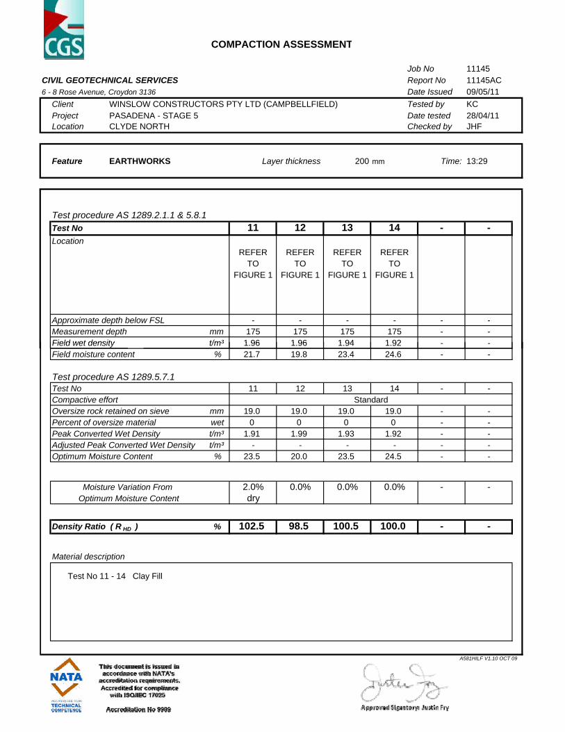
COMPACTION ASSESSMENT
Job No 11145CIVIL GEOTECHNICAL SERVICES Report No 11145AC 6 - 8 Rose Avenue, Croydon 3136 Date Issued 09/05/11
Client WINSLOW CONSTRUCTORS PTY LTD (CAMPBELLFIELD) Tested by KC Project PASADENA - STAGE 5 Date tested 28/04/11Location CLYDE NORTH Checked by JHF
Feature EARTHWORKS 200 mm Time: 13:29
Test procedure AS 1289.2.1.1 & 5.8.1Test No 11 12 13 14 - -Location
REFER REFER REFER REFERTO TO TO TO
FIGURE 1 FIGURE 1 FIGURE 1 FIGURE 1
Approximate depth below FSL - - - - - -Measurement depth mm 175 175 175 175 - -Field wet density t/m³ 1 96 1 96 1 94 1 92
Layer thickness
Field wet density t/m³ 1.96 1.96 1.94 1.92 - -Field moisture content % 21.7 19.8 23.4 24.6 - -
Test procedure AS 1289.5.7.1Test No 11 12 13 14 - -Compactive effortOversize rock retained on sieve mm 19.0 19.0 19.0 19.0 - -Percent of oversize material wet 0 0 0 0 - -Peak Converted Wet Density t/m³ 1.91 1.99 1.93 1.92 - -Adjusted Peak Converted Wet Density t/m³ - - - - - -Optimum Moisture Content % 23.5 20.0 23.5 24.5 - -
Moisture Variation From 2.0% 0.0% 0.0% 0.0% - -Optimum Moisture Content dry
Density Ratio ( R HD ) % 102.5 98.5 100.5 100.0 - -
Material description
Test No 11 - 14 Clay Fill
Standard
A581HILF V1.10 OCT 09

COMPACTION ASSESSMENT
Job No 11145CIVIL GEOTECHNICAL SERVICES Report No 11145AD 6 - 8 Rose Avenue, Croydon 3136 Date Issued 09/05/11
Client WINSLOW CONSTRUCTORS PTY LTD (CAMPBELLFIELD) Tested by KC Project PASADENA - STAGE 5 Date tested 29/04/11Location CLYDE NORTH Checked by JHF
Feature EARTHWORKS 200 mm Time: 14:23
Test procedure AS 1289.2.1.1 & 5.8.1Test No 15 16 17 18 19 -Location
REFER REFER REFER REFER REFERTO TO TO TO TO
FIGURE 1 FIGURE 1 FIGURE 1 FIGURE 1 FIGURE 1
Approximate depth below FSL - - - - - -Measurement depth mm 175 175 175 175 175 -Field wet density t/m³ 1 99 1 86 2 00 1 99 1 84
Layer thickness
Field wet density t/m³ 1.99 1.86 2.00 1.99 1.84 -Field moisture content % 16.6 26.3 20.2 17.3 27.1 -
Test procedure AS 1289.5.7.1Test No 15 16 17 18 19 -Compactive effortOversize rock retained on sieve mm 19.0 19.0 19.0 19.0 19.0 -Percent of oversize material wet 0 0 0 0 0 -Peak Converted Wet Density t/m³ 1.99 1.90 1.96 1.99 1.85 -Adjusted Peak Converted Wet Density t/m³ - - - - - -Optimum Moisture Content % 19.0 25.5 22.5 19.0 26.5 -
Moisture Variation From 2.5% 0.5% 2.0% 1.5% 0.5% -Optimum Moisture Content dry wet dry dry wet
Density Ratio ( R HD ) % 100.0 98.0 102.5 100.0 99.5 -
Material description
Test No 15 - 19 Clay Fill
Standard
A581HILF V1.10 OCT 09
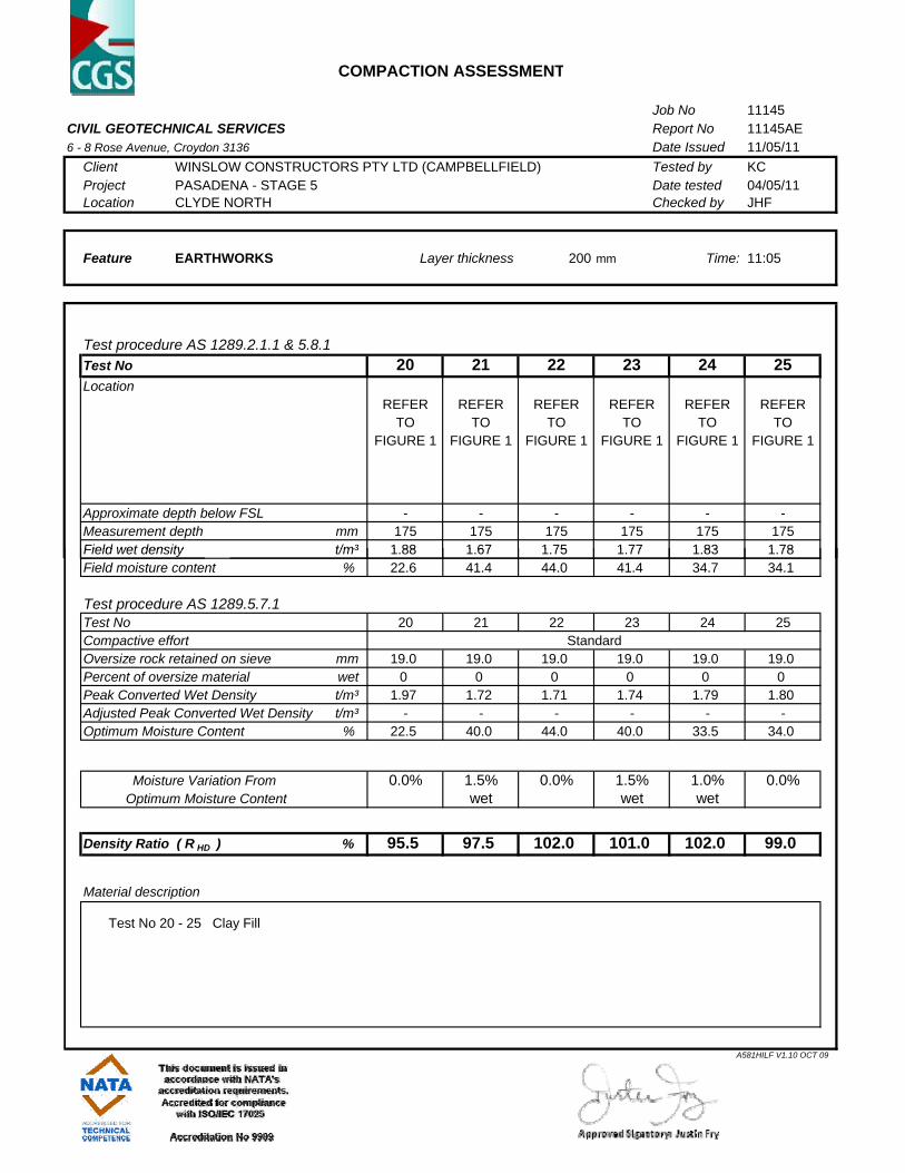
COMPACTION ASSESSMENT
Job No 11145CIVIL GEOTECHNICAL SERVICES Report No 11145AE 6 - 8 Rose Avenue, Croydon 3136 Date Issued 11/05/11
Client WINSLOW CONSTRUCTORS PTY LTD (CAMPBELLFIELD) Tested by KC Project PASADENA - STAGE 5 Date tested 04/05/11Location CLYDE NORTH Checked by JHF
Feature EARTHWORKS 200 mm Time: 11:05
Test procedure AS 1289.2.1.1 & 5.8.1Test No 20 21 22 23 24 25Location
REFER REFER REFER REFER REFER REFERTO TO TO TO TO TO
FIGURE 1 FIGURE 1 FIGURE 1 FIGURE 1 FIGURE 1 FIGURE 1
Approximate depth below FSL - - - - - -Measurement depth mm 175 175 175 175 175 175Field wet density t/m³ 1 88 1 67 1 75 1 77 1 83 1 78
Layer thickness
Field wet density t/m³ 1.88 1.67 1.75 1.77 1.83 1.78Field moisture content % 22.6 41.4 44.0 41.4 34.7 34.1
Test procedure AS 1289.5.7.1Test No 20 21 22 23 24 25Compactive effortOversize rock retained on sieve mm 19.0 19.0 19.0 19.0 19.0 19.0Percent of oversize material wet 0 0 0 0 0 0Peak Converted Wet Density t/m³ 1.97 1.72 1.71 1.74 1.79 1.80Adjusted Peak Converted Wet Density t/m³ - - - - - -Optimum Moisture Content % 22.5 40.0 44.0 40.0 33.5 34.0
Moisture Variation From 0.0% 1.5% 0.0% 1.5% 1.0% 0.0%Optimum Moisture Content wet wet wet
Density Ratio ( R HD ) % 95.5 97.5 102.0 101.0 102.0 99.0
Material description
Test No 20 - 25 Clay Fill
Standard
A581HILF V1.10 OCT 09
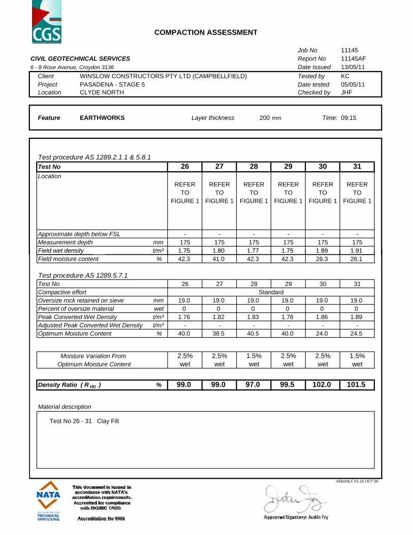
COMPACTION ASSESSMENT
Job No 11145CIVIL GEOTECHNICAL SERVICES Report No 11145AF 6 - 8 Rose Avenue, Croydon 3136 Date Issued 13/05/11
Client WINSLOW CONSTRUCTORS PTY LTD (CAMPBELLFIELD) Tested by KC Project PASADENA - STAGE 5 Date tested 05/05/11Location CLYDE NORTH Checked by JHF
Feature EARTHWORKS 200 mm Time: 09:15
Test procedure AS 1289.2.1.1 & 5.8.1Test No 26 27 28 29 30 31Location
REFER REFER REFER REFER REFER REFERTO TO TO TO TO TO
FIGURE 1 FIGURE 1 FIGURE 1 FIGURE 1 FIGURE 1 FIGURE 1
Approximate depth below FSL - - - - - -Measurement depth mm 175 175 175 175 175 175Field wet density t/m³ 1 75 1 80 1 77 1 75 1 89 1 91
Layer thickness
Field wet density t/m³ 1.75 1.80 1.77 1.75 1.89 1.91Field moisture content % 42.3 41.0 42.3 42.3 26.3 26.1
Test procedure AS 1289.5.7.1Test No 26 27 28 29 30 31Compactive effortOversize rock retained on sieve mm 19.0 19.0 19.0 19.0 19.0 19.0Percent of oversize material wet 0 0 0 0 0 0Peak Converted Wet Density t/m³ 1.76 1.82 1.83 1.76 1.86 1.89Adjusted Peak Converted Wet Density t/m³ - - - - - -Optimum Moisture Content % 40.0 38.5 40.5 40.0 24.0 24.5
Moisture Variation From 2.5% 2.5% 1.5% 2.5% 2.5% 1.5%Optimum Moisture Content wet wet wet wet wet wet
Density Ratio ( R HD ) % 99.0 99.0 97.0 99.5 102.0 101.5
Material description
Test No 26 - 31 Clay Fill
Standard
A581HILF V1.10 OCT 09

COMPACTION ASSESSMENT
Job No 11145CIVIL GEOTECHNICAL SERVICES Report No 11145AG 6 - 8 Rose Avenue, Croydon 3136 Date Issued 05/05/11
Client WINSLOW CONSTRUCTORS PTY LTD (CAMPBELLFIELD) Tested by KC Project PASADENA - STAGE 5 Date tested 05/05/11Location CLYDE NORTH Checked by JHF
Feature EARTHWORKS 200 mm Time: 10:30
Test procedure AS 1289.2.1.1 & 5.8.1Test No 32 33 - - - -Location
REFER REFERTO TO
FIGURE 1 FIGURE 1
Approximate depth below FSL - - - - - -Measurement depth mm 175 175 - - - -Field wet density t/m³ 1 99 1 78
Layer thickness
Field wet density t/m³ 1.99 1.78 - - - -Field moisture content % 25.0 37.6 - - - -
Test procedure AS 1289.5.7.1Test No 32 33 - - - -Compactive effortOversize rock retained on sieve mm 19.0 19.0 - - - -Percent of oversize material wet 0 0 - - - -Peak Converted Wet Density t/m³ 1.92 1.78 - - - -Adjusted Peak Converted Wet Density t/m³ - - - - - -Optimum Moisture Content % 24.5 35.0 - - - -
Moisture Variation From 0.5% 2.5% - - - -Optimum Moisture Content wet wet
Density Ratio ( R HD ) % 103.5 100.0 - - - -
Material description
Test No 32 - 33 Clay Fill
Standard
A581HILF V1.10 OCT 09

COMPACTION ASSESSMENT
Job No 11145CIVIL GEOTECHNICAL SERVICES Report No 11145AH 6 - 8 Rose Avenue, Croydon 3136 Date Issued 17/05/11
Client WINSLOW CONSTRUCTORS PTY LTD (CAMPBELLFIELD) Tested by KC Project PASADENA - STAGE 5 Date tested 06/05/11Location CLYDE NORTH Checked by JHF
Feature EARTHWORKS 200 mm Time: 14:27
Test procedure AS 1289.2.1.1 & 5.8.1Test No 34 35 - - - -Location
REFER REFERTO TO
FIGURE 1 FIGURE 1
Approximate depth below FSL - - - - - -Measurement depth mm 175 175 - - - -Field wet density t/m³ 1 83 1 84
Layer thickness
Field wet density t/m³ 1.83 1.84 - - - -Field moisture content % 35.5 31.5 - - - -
Test procedure AS 1289.5.7.1Test No 34 35 - - - -Compactive effortOversize rock retained on sieve mm 19.0 19.0 - - - -Percent of oversize material wet 0 0 - - - -Peak Converted Wet Density t/m³ 1.73 1.83 - - - -Adjusted Peak Converted Wet Density t/m³ - - - - - -Optimum Moisture Content % 33.5 29.5 - - - -
Moisture Variation From 2.0% 2.0% - - - -Optimum Moisture Content wet wet
Density Ratio ( R HD ) % 105.5 100.5 - - - -
Material description
Test No 34 - 35 Clay Fill
Standard
A581HILF V1.10 OCT 09

COMPACTION ASSESSMENT
Job No 11189CIVIL GEOTECHNICAL SERVICES Report No 11189AA 6 - 8 Rose Avenue, Croydon 3136 Date Issued 16/05/11
Client WINSLOW CONSTRUCTORS PTY LTD (CAMPBELLFIELD) Tested by KC Project PASADENA - STAGE 5 Date tested 06/05/11Location CLYDE NORTH Checked by JHF
Feature EARTHWORKS 200 mm Time: 11:57
Test procedure AS 1289.2.1.1 & 5.8.1Test No 1 2 3 4 - -Location
REFER REFER REFER REFERTO TO TO TO
FIGURE 1 FIGURE 1 FIGURE 1 FIGURE 1
Approximate depth below FSL - - - - - -Measurement depth mm 175 175 175 175 - -Field wet density t/m³ 1 88 1 74 1 83 1 93
Layer thickness
Field wet density t/m³ 1.88 1.74 1.83 1.93 - -Field moisture content % 27.8 38.2 35.5 30.7 - -
Test procedure AS 1289.5.7.1Test No 1 2 3 4 - -Compactive effortOversize rock retained on sieve mm 19.0 19.0 19.0 19.0 - -Percent of oversize material wet 0 0 0 0 - -Peak Converted Wet Density t/m³ 1.87 1.71 1.79 1.92 - -Adjusted Peak Converted Wet Density t/m³ - - - - - -Optimum Moisture Content % 27.0 37.0 33.5 29.0 - -
Moisture Variation From 1.0% 1.0% 2.0% 2.0% - -Optimum Moisture Content wet wet wet wet
Density Ratio ( R HD ) % 100.5 101.5 102.0 100.5 - -
Material description
Test No 1 - 4 Clay Fill
Standard
A581HILF V1.10 OCT 09
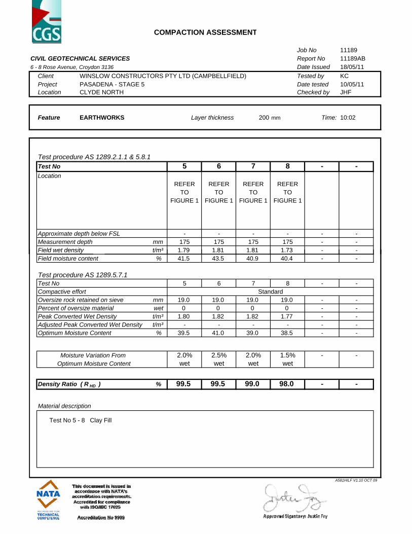
COMPACTION ASSESSMENT
Job No 11189CIVIL GEOTECHNICAL SERVICES Report No 11189AB 6 - 8 Rose Avenue, Croydon 3136 Date Issued 18/05/11
Client WINSLOW CONSTRUCTORS PTY LTD (CAMPBELLFIELD) Tested by KC Project PASADENA - STAGE 5 Date tested 10/05/11Location CLYDE NORTH Checked by JHF
Feature EARTHWORKS 200 mm Time: 10:02
Test procedure AS 1289.2.1.1 & 5.8.1Test No 5 6 7 8 - -Location
REFER REFER REFER REFERTO TO TO TO
FIGURE 1 FIGURE 1 FIGURE 1 FIGURE 1
Approximate depth below FSL - - - - - -Measurement depth mm 175 175 175 175 - -Field wet density t/m³ 1 79 1 81 1 81 1 73
Layer thickness
Field wet density t/m³ 1.79 1.81 1.81 1.73 - -Field moisture content % 41.5 43.5 40.9 40.4 - -
Test procedure AS 1289.5.7.1Test No 5 6 7 8 - -Compactive effortOversize rock retained on sieve mm 19.0 19.0 19.0 19.0 - -Percent of oversize material wet 0 0 0 0 - -Peak Converted Wet Density t/m³ 1.80 1.82 1.82 1.77 - -Adjusted Peak Converted Wet Density t/m³ - - - - - -Optimum Moisture Content % 39.5 41.0 39.0 38.5 - -
Moisture Variation From 2.0% 2.5% 2.0% 1.5% - -Optimum Moisture Content wet wet wet wet
Density Ratio ( R HD ) % 99.5 99.5 99.0 98.0 - -
Material description
Test No 5 - 8 Clay Fill
Standard
A581HILF V1.10 OCT 09

COMPACTION ASSESSMENT
Job No 11370CIVIL GEOTECHNICAL SERVICES Report No 11370AA 6 - 8 Rose Avenue, Croydon 3136 Date Issued 07/10/11
Client WINSLOW CONSTRUCTORS PTY LTD (CAMPBELLFIELD) Tested by TG Project PASADENA - STAGE 5 Date tested 03/10/11Location CLYDE Checked by JHF
Feature EARTHWORKS 200 mm Time: 13:15
Test procedure AS 1289.2.1.1 & 5.8.1Test No 1 2 3 - - -Location
REFER REFER REFER TO TO TO
FIGURE 1 FIGURE 1 FIGURE 1
Approximate depth below FSL - - - - - -Measurement depth mm 175 175 175 - - -Field wet density t/m³ 1 83 1 77 1 76
Layer thickness
Field wet density t/m³ 1.83 1.77 1.76 - - -Field moisture content % 30.4 38.7 39.5 - - -
Test procedure AS 1289.5.7.1Test No 1 2 3 - - -Compactive effortOversize rock retained on sieve mm 19.0 19.0 19.0 - - -Percent of oversize material wet 0 0 0 - - -Peak Converted Wet Density t/m³ 1.87 1.71 1.77 - - -Adjusted Peak Converted Wet Density t/m³ - - - - - -Optimum Moisture Content % 29.5 38.0 38.5 - - -
Moisture Variation From 1.0% 1.0% 1.0% - - -Optimum Moisture Content wet wet wet
Density Ratio ( R HD ) % 98.0 104.0 99.5 - - -
Material description
Test No 1 - 3 Clay Fill
Standard
A581HILF V1.10 OCT 09

COMPACTION ASSESSMENT
Job No 11370CIVIL GEOTECHNICAL SERVICES Report No 11370AB 6 - 8 Rose Avenue, Croydon 3136 Date Issued 07/10/11
Client WINSLOW CONSTRUCTORS PTY LTD (CAMPBELLFIELD) Tested by JHF Project PASADENA - STAGE 5 Date tested 04/10/11Location CLYDE Checked by JHF
Feature EARTHWORKS 200 mm Time: 10:51
Test procedure AS 1289.2.1.1 & 5.8.1Test No 4 5 6 - - -Location
REFER REFER REFER TO TO TO
FIGURE 1 FIGURE 1 FIGURE 1
Approximate depth below FSL - - - - - -Measurement depth mm 175 175 175 - - -Field wet density t/m³ 1 72 1 85 1 93
Layer thickness
Field wet density t/m³ 1.72 1.85 1.93 - - -Field moisture content % 34.0 29.8 26.3 - - -
Test procedure AS 1289.5.7.1Test No 4 5 6 - - -Compactive effortOversize rock retained on sieve mm 19.0 19.0 19.0 - - -Percent of oversize material wet 0 0 0 - - -Peak Converted Wet Density t/m³ 1.81 1.95 1.98 - - -Adjusted Peak Converted Wet Density t/m³ - - - - - -Optimum Moisture Content % 33.0 30.5 27.0 - - -
Moisture Variation From 1.0% 0.5% 1.0% - - -Optimum Moisture Content wet dry dry
Density Ratio ( R HD ) % 95.0 95.0 97.5 - - -
Material description
Test No 4 - 6 Clay Fill
Standard
A581HILF V1.10 OCT 09

COMPACTION ASSESSMENT
Job No 11370CIVIL GEOTECHNICAL SERVICES Report No 11370AC 6 - 8 Rose Avenue, Croydon 3136 Date Issued 07/10/11
Client WINSLOW CONSTRUCTORS PTY LTD (CAMPBELLFIELD) Tested by TG Project PASADENA - STAGE 5 Date tested 05/10/11Location CLYDE Checked by JHF
Feature EARTHWORKS 200 mm Time: 09:10
Test procedure AS 1289.2.1.1 & 5.8.1Test No 7 8 9 - - -Location
REFER REFER REFER TO TO TO
FIGURE 1 FIGURE 1 FIGURE 1
Approximate depth below FSL - - - - - -Measurement depth mm 175 175 175 - - -Field wet density t/m³ 1 90 1 89 1 97
Layer thickness
Field wet density t/m³ 1.90 1.89 1.97 - - -Field moisture content % 21.9 22.2 22.6 - - -
Test procedure AS 1289.5.7.1Test No 7 8 9 - - -Compactive effortOversize rock retained on sieve mm 19.0 19.0 19.0 - - -Percent of oversize material wet 0 0 0 - - -Peak Converted Wet Density t/m³ 2.00 1.98 2.04 - - -Adjusted Peak Converted Wet Density t/m³ - - - - - -Optimum Moisture Content % 21.0 22.0 24.5 - - -
Moisture Variation From 0.5% 0.5% 2.0% - - -Optimum Moisture Content wet wet dry
Density Ratio ( R HD ) % 95.0 95.5 96.5 - - -
Material description
Test No 7 - 9 Clay Fill
Standard
A581HILF V1.10 OCT 09

COMPACTION ASSESSMENT
Job No 11370CIVIL GEOTECHNICAL SERVICES Report No 11370AD 6 - 8 Rose Avenue, Croydon 3136 Date Issued 11/10/11
Client WINSLOW CONSTRUCTORS PTY LTD (CAMPBELLFIELD) Tested by JHF Project PASADENA - STAGE 5 Date tested 06/10/11Location CLYDE Checked by JHF
Feature EARTHWORKS 200 mm Time: 12:44
Test procedure AS 1289.2.1.1 & 5.8.1Test No 10 11 12 - - -Location
REFER REFER REFER TO TO TO
FIGURE 1 FIGURE 1 FIGURE 1
Approximate depth below FSL - - - - - -Measurement depth mm 175 175 175 - - -Field wet density t/m³ 1 99 1 98 2 01
Layer thickness
Field wet density t/m³ 1.99 1.98 2.01 - - -Field moisture content % 21.5 24.9 21.5 - - -
Test procedure AS 1289.5.7.1Test No 10 11 12 - - -Compactive effortOversize rock retained on sieve mm 19.0 19.0 19.0 - - -Percent of oversize material wet 0 0 0 - - -Peak Converted Wet Density t/m³ 2.05 1.97 2.01 - - -Adjusted Peak Converted Wet Density t/m³ - - - - - -Optimum Moisture Content % 19.5 24.5 21.0 - - -
Moisture Variation From 2.0% 0.5% 0.5% - - -Optimum Moisture Content wet wet wet
Density Ratio ( R HD ) % 97.0 100.5 100.0 - - -
Material description
Test No 10 - 12 Clay Fill
Standard
A581HILF V1.10 OCT 09
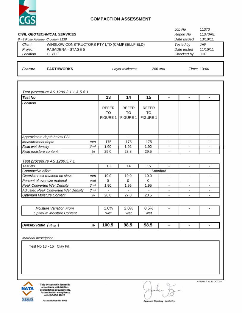
COMPACTION ASSESSMENT
Job No 11370CIVIL GEOTECHNICAL SERVICES Report No 11370AE 6 - 8 Rose Avenue, Croydon 3136 Date Issued 13/10/11
Client WINSLOW CONSTRUCTORS PTY LTD (CAMPBELLFIELD) Tested by JHF Project PASADENA - STAGE 5 Date tested 11/10/11Location CLYDE Checked by JHF
Feature EARTHWORKS 200 mm Time: 13:44
Test procedure AS 1289.2.1.1 & 5.8.1Test No 13 14 15 - - -Location
REFER REFER REFER TO TO TO
FIGURE 1 FIGURE 1 FIGURE 1
Approximate depth below FSL - - - - - -Measurement depth mm 175 175 175 - - -Field wet density t/m³ 1 90 1 92 1 92
Layer thickness
Field wet density t/m³ 1.90 1.92 1.92 - - -Field moisture content % 29.0 28.8 29.5 - - -
Test procedure AS 1289.5.7.1Test No 13 14 15 - - -Compactive effortOversize rock retained on sieve mm 19.0 19.0 19.0 - - -Percent of oversize material wet 0 0 0 - - -Peak Converted Wet Density t/m³ 1.90 1.95 1.95 - - -Adjusted Peak Converted Wet Density t/m³ - - - - - -Optimum Moisture Content % 28.0 27.0 28.5 - - -
Moisture Variation From 1.0% 2.0% 0.5% - - -Optimum Moisture Content wet wet wet
Density Ratio ( R HD ) % 100.5 98.5 98.5 - - -
Material description
Test No 13 - 15 Clay Fill
Standard
A581HILF V1.10 OCT 09

COMPACTION ASSESSMENT
Job No 11370CIVIL GEOTECHNICAL SERVICES Report No 11370AF 6 - 8 Rose Avenue, Croydon 3136 Date Issued 28/10/11
Client WINSLOW CONSTRUCTORS PTY LTD (CAMPBELLFIELD) Tested by JHF Project PASADENA - STAGE 5 Date tested 12/10/11Location CLYDE Checked by JHF
Feature EARTHWORKS 200 mm Time: 13:50
Test procedure AS 1289.2.1.1 & 5.8.1Test No 16 17 18 - - -Location
REFER REFER REFER TO TO TO
FIGURE 1 FIGURE 1 FIGURE 1
Approximate depth below FSL - - - - - -Measurement depth mm 175 175 175 - - -Field wet density t/m³ 1 97 1 89 2 03
Layer thickness
Field wet density t/m³ 1.97 1.89 2.03 - - -Field moisture content % 25.3 32.0 19.4 - - -
Test procedure AS 1289.5.7.1Test No 16 17 18 - - -Compactive effortOversize rock retained on sieve mm 19.0 19.0 19.0 - - -Percent of oversize material wet 0 0 0 - - -Peak Converted Wet Density t/m³ 1.95 1.93 2.05 - - -Adjusted Peak Converted Wet Density t/m³ - - - - - -Optimum Moisture Content % 23.5 32.0 19.0 - - -
Moisture Variation From 1.5% 0.0% 0.5% - - -Optimum Moisture Content wet wet
Density Ratio ( R HD ) % 101.0 98.0 99.0 - - -
Material description
Test No 16 - 18 Clay Fill
Standard
A581HILF V1.10 OCT 09

COMPACTION ASSESSMENT
Job No 11370CIVIL GEOTECHNICAL SERVICES Report No 11370AG 6 - 8 Rose Avenue, Croydon 3136 Date Issued 28/10/11
Client WINSLOW CONSTRUCTORS PTY LTD (CAMPBELLFIELD) Tested by TG Project PASADENA - STAGE 5 Date tested 13/10/11Location CLYDE Checked by JHF
Feature EARTHWORKS 200 mm Time: 14:15
Test procedure AS 1289.2.1.1 & 5.8.1Test No 19 20 21 - - -Location
REFER REFER REFER TO TO TO
FIGURE 1 FIGURE 1 FIGURE 1
Approximate depth below FSL - - - - - -Measurement depth mm 175 175 175 - - -Field wet density t/m³ 1 90 1 89 1 89
Layer thickness
Field wet density t/m³ 1.90 1.89 1.89 - - -Field moisture content % 25.7 26.9 27.8 - - -
Test procedure AS 1289.5.7.1Test No 19 20 21 - - -Compactive effortOversize rock retained on sieve mm 19.0 19.0 19.0 - - -Percent of oversize material wet 0 0 0 - - -Peak Converted Wet Density t/m³ 1.97 1.93 1.93 - - -Adjusted Peak Converted Wet Density t/m³ - - - - - -Optimum Moisture Content % 24.0 26.5 26.0 - - -
Moisture Variation From 1.5% 0.5% 1.5% - - -Optimum Moisture Content wet wet wet
Density Ratio ( R HD ) % 96.5 98.5 98.0 - - -
Material description
Test No 19 - 21 Clay Fill
Standard
A581HILF V1.10 OCT 09

COMPACTION ASSESSMENT
Job No 11370CIVIL GEOTECHNICAL SERVICES Report No 11370AH 6 - 8 Rose Avenue, Croydon 3136 Date Issued 28/10/11
Client WINSLOW CONSTRUCTORS PTY LTD (CAMPBELLFIELD) Tested by JHF Project PASADENA - STAGE 5 Date tested 14/10/11Location CLYDE Checked by JHF
Feature EARTHWORKS 200 mm Time: 12:27
Test procedure AS 1289.2.1.1 & 5.8.1Test No 22 23 24 25 - -Location
REFER REFER REFER REFER TO TO TO TO
FIGURE 1 FIGURE 1 FIGURE 1 FIGURE 1
Approximate depth below FSL - - - - - -Measurement depth mm 175 175 175 175 - -Field wet density t/m³ 1 92 1 95 1 95 1 91
Layer thickness
Field wet density t/m³ 1.92 1.95 1.95 1.91 - -Field moisture content % 27.2 15.9 23.8 24.7 - -
Test procedure AS 1289.5.7.1Test No 22 23 24 25 - -Compactive effortOversize rock retained on sieve mm 19.0 19.0 19.0 19.0 - -Percent of oversize material wet 0 0 0 0 - -Peak Converted Wet Density t/m³ 1.92 2.04 1.93 1.95 - -Adjusted Peak Converted Wet Density t/m³ - - - - - -Optimum Moisture Content % 26.5 16.0 23.5 24.5 - -
Moisture Variation From 0.5% 0.0% 0.5% 0.0% - -Optimum Moisture Content wet wet
Density Ratio ( R HD ) % 100.0 95.5 101.0 98.0 - -
Material description
Test No 22 - 25 Clay Fill
Standard
A581HILF V1.10 OCT 09

COMPACTION ASSESSMENT
Job No 11370CIVIL GEOTECHNICAL SERVICES Report No 11370AI 6 - 8 Rose Avenue, Croydon 3136 Date Issued 28/10/11
Client WINSLOW CONSTRUCTORS PTY LTD (CAMPBELLFIELD) Tested by KC Project PASADENA - STAGE 5 Date tested 17/10/11Location CLYDE Checked by JHF
Feature EARTHWORKS 200 mm Time: 15:05
Test procedure AS 1289.2.1.1 & 5.8.1Test No 26 27 28 - - -Location
REFER REFER REFER TO TO TO
FIGURE 1 FIGURE 1 FIGURE 1
Approximate depth below FSL - - - - - -Measurement depth mm 175 175 175 - - -Field wet density t/m³ 1 80 1 91 2 00
Layer thickness
Field wet density t/m³ 1.80 1.91 2.00 - - -Field moisture content % 31.5 17.9 17.6 - - -
Test procedure AS 1289.5.7.1Test No 26 27 28 - - -Compactive effortOversize rock retained on sieve mm 19.0 19.0 19.0 - - -Percent of oversize material wet 0 0 0 - - -Peak Converted Wet Density t/m³ 1.86 2.01 2.02 - - -Adjusted Peak Converted Wet Density t/m³ - - - - - -Optimum Moisture Content % 31.0 18.0 18.0 - - -
Moisture Variation From 0.5% 0.5% 0.5% - - -Optimum Moisture Content wet dry dry
Density Ratio ( R HD ) % 97.0 95.0 99.0 - - -
Material description
Test No 26 - 28 Clay Fill
Standard
A581HILF V1.10 OCT 09
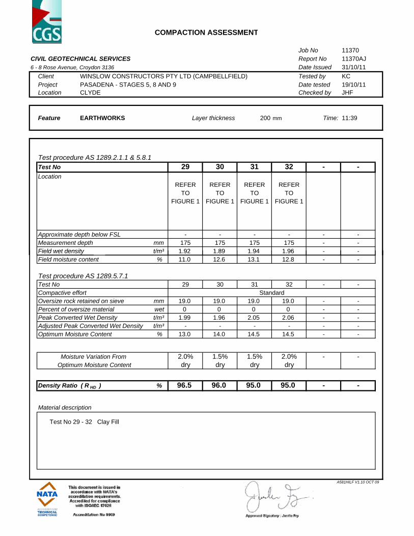
COMPACTION ASSESSMENT
Job No 11370CIVIL GEOTECHNICAL SERVICES Report No 11370AJ 6 - 8 Rose Avenue, Croydon 3136 Date Issued 31/10/11
Client WINSLOW CONSTRUCTORS PTY LTD (CAMPBELLFIELD) Tested by KC Project PASADENA - STAGES 5, 8 AND 9 Date tested 19/10/11Location CLYDE Checked by JHF
Feature EARTHWORKS 200 mm Time: 11:39
Test procedure AS 1289.2.1.1 & 5.8.1Test No 29 30 31 32 - -Location
REFER REFER REFER REFER TO TO TO TO
FIGURE 1 FIGURE 1 FIGURE 1 FIGURE 1
Approximate depth below FSL - - - - - -Measurement depth mm 175 175 175 175 - -Field wet density t/m³ 1 92 1 89 1 94 1 96
Layer thickness
Field wet density t/m³ 1.92 1.89 1.94 1.96 - -Field moisture content % 11.0 12.6 13.1 12.8 - -
Test procedure AS 1289.5.7.1Test No 29 30 31 32 - -Compactive effortOversize rock retained on sieve mm 19.0 19.0 19.0 19.0 - -Percent of oversize material wet 0 0 0 0 - -Peak Converted Wet Density t/m³ 1.99 1.96 2.05 2.06 - -Adjusted Peak Converted Wet Density t/m³ - - - - - -Optimum Moisture Content % 13.0 14.0 14.5 14.5 - -
Moisture Variation From 2.0% 1.5% 1.5% 2.0% - -Optimum Moisture Content dry dry dry dry
Density Ratio ( R HD ) % 96.5 96.0 95.0 95.0 - -
Material description
Test No 29 - 32 Clay Fill
Standard
A581HILF V1.10 OCT 09